Safety instructions Iwaki Electromagnetic Metering Pump EJ ...

Read this manual before use of product
IWAKI Magnetic Drive Pump
MX-F250~F403
Instruction Manual (Europe Edition)
T502 '03/02
( )Country codes
IWAKI CO.,LTD. 6-6 Kanda-Sudacho 2-chome Chiyoda-ku Tokyo 101-8558 JapanTEL:(81)3 3254 2935 FAX:3 3252 8892(http://www.iwakipumps.jp)
Germany : IWAKI EUROPE GmbHItaly : IWAKI Italia S.R.L.Denmark : IWAKI Pumper A/SSweden : IWAKI Sverige ABFinland : IWAKI Suomi OyNorway : IWAKI Norge ASFrance : IWAKI France S.A.U.K. : IWAKI PUMPS (UK) LTDSwitzerland : IWAKI (Schweiz) AGAustria : IWAKI (Austria) GmbHHolland : IWAKI Holland B.V.Spain : IWAKI Iberica Pumps,S.A.Belgium : IWAKI Belgium n.v.
TEL : (49)2154 9254 0 FAX : 2154 1028TEL : (39)02 990 3931 FAX : 02 990 42888TEL : (45)48 24 2345 FAX : 48 24 2346TEL : (46)8 511 72900 FAX : 8 511 72922TEL : (358)9 2742714 FAX : 9 2742715TEL : (47)66 81 16 60 FAX : 66 81 16 61TEL : (33)1 69 63 33 70 FAX : 1 64 49 92 73TEL : (44)1743 231363 FAX : 1743 366507TEL : (41)32 3235024 FAX : 32 3226084TEL : (43)2236 33469 FAX : 2236 33469TEL : (31)297 241121 FAX : 297 273902TEL : (34)943 630030 FAX : 943 628799TEL : (32)1430 7007 FAX : 1430 7008
U.S.A. : IWAKI WALCHEM CorporationAustralia : IWAKI Pumps Australia Pty. Ltd.Singapore : IWAKI Singapore Pte. Ltd.Indonesia : IWAKI Singapore (Indonesia Branch)Malaysia : IWAKIm Sdn. Bhd.Taiwan : IWAKI Pumps Taiwan Co., Ltd.Thailand : IWAKI (Thailand) Co.,Ltd.Hong Kong : IWAKI Pumps Co., Ltd.China : GFTZ IWAKI Engineering & Trading Co., Ltd.China : IWAKI Pumps Co., Ltd. (Beijing office)China : IWAKI Pumps (Shanghai) Co., Ltd.Philippines : IWAKI Chemical Pumps Philippines, Inc.Korea : IWAKI Korea Co.,Ltd.
TEL : (1)508 429 1440 FAX : 508 429 1386TEL : (61)2 9899 2411 FAX : 2 9899 2421TEL : (65)763 2744 FAX : 763 2372TEL : (62)21 690 6607 FAX : 21 690 6612TEL : (60)3 7803 8807 FAX : 3 7803 4800TEL : (886)2 8227 6900 FAX : 2 8227 6818TEL : (66)2 320 1303 FAX : 2 322 2477TEL : (852)2 607 1168 FAX : 2 607 1000TEL : (86)20 8435 0603 FAX : 20 8435 9181TEL : (86)10 6442 7713 FAX : 10 6442 7712TEL : (86)21 6272 7502 FAX : 21 6272 6929TEL : (63)2 888 0245 FAX : 2 843 3096TEL : (82)2 3474 0523 FAX : 2 3474 0221

Contents
Safety section............................................................................... 1~5
Outline of product...................................................................... 6~121. Unpacking and inspection....................................................... 72. Principle of operation .............................................................. 73. Model identification code ........................................................ 84. Specification ........................................................................... 95. Dimension ............................................................................... 96. Name of parts and construction............................................ 107. Main parts and label ............................................................. 13
Installation.................................................................................14~221. Before use............................................................................. 152. Installation............................................................................. 173. Piping .................................................................................... 194. Wiring .................................................................................... 22
Operation.................................................................................. 23~271. Precautions on operation ...................................................... 242. Preparation for operation ...................................................... 253. Operation .............................................................................. 26
Maintenance ............................................................................. 28~411. Troubleshooting ..................................................................... 292. Maintenance and inspection ................................................. 32
354. Disassembling and assembling ............................................ 36
Thank you for selecting the Iwaki Magnetic Drive Pump MX-F Series. This instruction
manual has been prepared to ensure correct and safe handling of the pump.
Please read this manual carefully and thoroughly prior to operating the pump.
Pay special attention to the "Safety Instruction to Prevent Personal Injuries," "Warning," and
"Caution" messages included in this manual.
This instruction manual should be kept by each end user and within reach of the actual
operator, for quick reference when needed.
3. Consumable parts ................................................................

For the Safe and Correct Handling of the Pump
Following two symbols describe the content to be observed.
Safety section
Warning
Caution
• Before use of the pump, read carefully this "Safety Section" to prevent accidents and to avoid the damage or loss of other assets.
• Observe and abide by the instructions described in this "Safety Section". These instructions are very important for protecting pump users or other persons from hazard or from loss of assets.
• Meaning of symbols Following two symbols describe the extent of hazards and loss which may brought if the
instructions are not observed or if the pump is wrongly used.
Nonobservance or misapplication of the contents of
the "Warning" could lead to a death or heavy injury
of person.
Prohibited action or procedure is indicated. Inside or
near this circle, a concrete activity to be prohibited is
depicted.
Nonobservance or misapplication of the contents of
the "Caution" could lead to a injury of person or
damage of assets.
Action or procedure which must be performed without
fail is indicated. Inside this circle, a concrete activity to
be performed is depicted.
- 1 -

Safety section
Warning
Caution
Caution
Prohibited
Caution
Caution
Wearprotective gear
Power off
• Damaged or deteriorated tools are very dangerous. Use qualified and suitable
tools only.
• Use of protectors: When disassembling, assembling, and conducting maintenance
or when handling a dangerous type of liquid or a liquid of unknown property, be sure
to wear safety gloves, a helmet, and protective shoes. In addition, when handling
wet-end parts, always wear protective goggles, masks, etc.
• To prevent death or injury from a falling pump, make sure the rope or chain used
for lifting the pump is not accidentally cut or disconnected during installation. Make
sure the rope or the chain used to lift the pump has sufficient strength in relation to the
pump weight.
• When lifting the pump with rope or chain, be sure to use lifting bolts (or rings).
Never use any other points for lifting the pump. Otherwise the pump may drop and
results in human injury.
• Always turn off the power supply prior to do maintenance or other works. Make
special provisions so that no other operator mistakenly turns on the power supply
while someone is working on the pump. In a noisy or poor visibity environment,
display a sign near the power supply switch to notify others that someone is
"WORKING" on the pump. Power supply mistakenly turned on during maintenance
may lead to personal injury.
• Magnetic field hazard
The magnetic drive pumps contain strong magnets which are located in magnet
capsule and drive magnet cylinder. The powerful magnetic fields could adversely
affect persons who are assisted by electronic devices such as pacemaker. etc.
• When handling a toxic or odorant liquid, ventilate the working area well. In
addition, the operator must wear protector gear (such as a safety mask, safety
goggles, and protective gloves).
- 2 -

Safety section
Warning
No Remodeling
Caution
Prohibited
Caution
Prohibited
• Plastic material parts (Casing, flange, baseplate)
Do not hold plastic material parts when you lift the pump. Otherwise plastic parts may
be broken and pump may drop resulting in human injury.
• No remodeling
Remodeling of the pump by the user may result in serious personal injury, electric
shock, or damage to the pump. Do not attempt remodeling as it is very dangerous.
• Cautions when dangerous liquids are transferred.
When the pumps are used to transfer the dangerous liquids mentioned as below, the
pumps always must be checked and watched so that the liquids can not be leaked.
The operation of the pumps leaking the liquids may result in personal injury and/or
explosion, fire accidents.
• Explosive and inflammable liquids
• Corrosive and toxic liquids
• Liquids harmful to human body
• Qualified operators only
The pump operator and pump operation supervisor must not allow any operators who
have little or no knowledge of the pump to run operate the pump. Pump operators
must have a sound knowledge of the pump and its operation.
• For specified application only
The pump is designed and manufactured to the specifications agreed upon by the
user and Iwaki. The use of a pump in any application other than those clearly
specified may result in injury or damage to the pump. Use the pump strictly in
accordance with the pump specifications and application range. If you change any
specification, contact Iwaki or your dealer.
• Run the pump at the specified power supply voltage indicated on the nameplate.
Otherwise, pump failure, fire or electric shock may result.
• Spill-out prevention measures
Suitable protective measures should be taken against any liquid spill-out accidents.
Never discharge hazardous liquid, including, but not limited to, chemical liquid, over
the ground or floor on the pump operating site. Follow local rules and regulations in
disposing of hazardous substances.
- 3 -
Safety section
Caution
Prohibited
Prohibited
Caution
Grounding
Prohibited
Prohibited
ElectricalShock
Caution
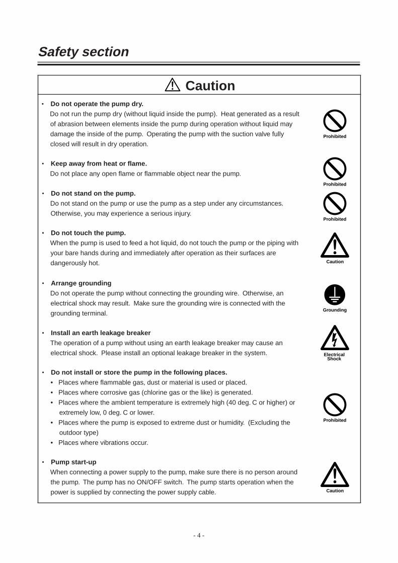
• Do not operate the pump dry.
Do not run the pump dry (without liquid inside the pump). Heat generated as a result
of abrasion between elements inside the pump during operation without liquid may
damage the inside of the pump. Operating the pump with the suction valve fully
closed will result in dry operation.
• Keep away from heat or flame.
Do not place any open flame or flammable object near the pump.
• Do not stand on the pump.
Do not stand on the pump or use the pump as a step under any circumstances.
Otherwise, you may experience a serious injury.
• Do not touch the pump.
When the pump is used to feed a hot liquid, do not touch the pump or the piping with
your bare hands during and immediately after operation as their surfaces are
dangerously hot.
• Arrange grounding
Do not operate the pump without connecting the grounding wire. Otherwise, an
electrical shock may result. Make sure the grounding wire is connected with the
grounding terminal.
• Install an earth leakage breaker
The operation of a pump without using an earth leakage breaker may cause an
electrical shock. Please install an optional leakage breaker in the system.
• Do not install or store the pump in the following places.
• Places where flammable gas, dust or material is used or placed.
• Places where corrosive gas (chlorine gas or the like) is generated.
• Places where the ambient temperature is extremely high (40 deg. C or higher) or
extremely low, 0 deg. C or lower.
• Places where the pump is exposed to extreme dust or humidity. (Excluding the
outdoor type)
• Places where vibrations occur.
• Pump start-up
When connecting a power supply to the pump, make sure there is no person around
the pump. The pump has no ON/OFF switch. The pump starts operation when the
power is supplied by connecting the power supply cable.
- 4 -

- 5 -
Safety section
Caution
Caution
• Foreign matter
Should foreign matter enter the pump, turn off the power at once and remove the
obstruction. Using the pump with foreign matter inside may cause damage to the
pump or a malfunction.
• Disposal of used pump
Disposal of used or damaged pumps must be done in accordance with local laws and
regulations. (Consult a licensed industrial waste products disposing company.)
• Strong magnetic power
The magnet used in the pump has a very high magnetic power. Be careful not to
allow your fingers to be seized by the magnet or to allow the magnet near any
electronic device which may be affected by the magnet's power.
• When suspending pump operation for a prolonged period
When suspending pump operation for a prolonged period, drain and clean the pump.
Take appropriate measures to prevent the foreign matter getting into the pump. If the
pump is not operated for a period longer than one year, replace the O ring and inspect
the pump inside.
• Countermeasure for static electricity
When low electric conductivity liquid such as ultra-pure water and fluor inactive
liquid(e.g.FluorinertTM) are handled, the static electricity may be generated in pump,
which may cause static discharge and break down of pump. Take countermeasure to
avoid and remove the static electrici.
• Ventilate
When toxic and odorous liquid is handled, ventilate the site to avoid poisoring.
OUTLINE OF PRODUCT
1. Unpacking and inspection .................... 7
2. Principle of operation ........................... 7
3. Model identification code ..................... 8
4. Specification......................................... 9
5. Dimension ............................................ 9
6. Name of parts and construction ......... 10
7. Main parts and label .......................... 13
- 6 -

1. Unpacking and inspection
2. Principle of operation
: Liquid flow
After unpacking, check the following points to confirm that
the delivered product and its accompanying parts and
elements are exactly what you ordered.
When lifting the pump please follow the procedure
mentioned "2. Installation" of "Installation" on page 17.
[1] Do the model and frequency indicated on the nameplate
conform to your order?
[2] Has the pump unit or any part of it been damaged or
have bolts and nuts been loosened during delivery?
[3] MFG.No. shows the year the product was manufactured.
(e.g.1) When first numeral is "7".
7××2××× The forth numeral of MFG.No. shows the
product was manufactured.
"2" shows the product was manufactured in the
year 2002.
(e.g.2) When first numeral is not "7".
××2××× The third numeral of MFG.No. shows the year
the product was manufactured.
If you find anything wrong, please refer to the dealer you
placed your order with.
The MX-F pump is a magnet-driven centrifugal type pump
developed for various applications.
The impeller inside the pump chamber (front casing) is
rotated by magnetic force to transfer liquid from the suction
side to the discharge side.
- 7 -
MODEL MX-F Hz

3. Model identification code
a s d f g
a Pump bore and motor output code
Code Pump bore (Suc. × Disch.) Motor output250 25A × 25A 0.37kW
400 40A × 40A 0.37kW
403 50A × 40A 2.2kW
Note) Motor is two pole, three phase.
401 40A × 40A 0.75kW
402 50A × 40A 1.5kW
s Combination of rubbing parts material
CF : High density carbon bearing × High purity alumina ceramic spindle
RF : Filler charged fluoroplastics bearing × High purity alumina ceramic spindle
KK : SiC bearing × SiC spindle
d O ring material
V : FKM
E : EPDM
A : Aflas®
f Impeller code
T : Pumped liquid specific gravity limit 1.2
V : Pumped liquid specific gravity limit 1.5 50 Hz
W: Pumped liquid specific gravity limit 2.0
X : Pumped liquid specific gravity limit 1.2
Y : Pumped liquid specific gravity limit 1.5 60 Hz
Z : Pumped liquid specific gravity limit 2.0
g Kind of motor
E : with IEC motor
MX – F400 CF V T E
- 8 -

- 9 -
4-i
H
de
L
f
gca
W
b
4. Specification
Model BoreSuc. × Disch.
Motoroutput
MX-F250T/X25 × 25
0.37kW
MX-F250V/YMX-F250W/Z
MX-F403W/Z
S.G.limit
Max. head(m)
StandardSpecification
(l/min, -m)
Max. Dischargecapacity(l/min)
1.2 13.2/13.4 50-11.3/11.8 15010.6/10.7 50-9.1/9.5 1407.8/8.8 50-6.4/7.5 130
19.5/17.8 250-15.3/14.7 480
Mass of pump (with motor)
MX-F250, F400 MX-F403
5. Dimension
Model W H e g iMX-F250 160 247.5 132.5 155.5 12MX-F400 140 219 124 144 12
MX-F402, F403 260 274 154 151 14×36
a b130 65110 54
208 80
L c d f130 115 82.598 95 81
200 120 83
50/60Hz
MX-F402V/Y1.2
20.3/17.6 200-16/15.2 430MX-F402W/Z 15.3/13.8 200-12.5/11.7 400MX-F403T/X 29.3/26.7 250-22.8/23.1 510
2.2kWMX-F403V/Y 25.1/22.4 250-19.4/19.2 500
MX-F401 MX-F402
MX-F401 160 249 130 72 130 115 134 97 178 12
MX-F400T/X
40 × 40
1.2 11.8/10.3 100-10.1/9.3 250MX-F400V/Y 9.3/8.6 100-8.1/7.6 230MX-F400W/Z 6.4/7.2 100-5.5/6.3 210MX-F401T/X 16.8/15.3 150-12.8/12.6 270
0.75kWMX-F401V/Y 14/13 150-10.8/10.4 260MX-F401W/Z 10.8/9.6 150-8.1/6.9 230MX-F402T/X
50 × 40
23.7/21.2 200-18.3/18.5 4401.5kW
1.51.8~2.0
1.51.8~2.0
1.21.5
1.8~2.0
1.51.8~2.0
1.21.5
1.8~2.0

6. Name of parts and construction
a MX-F250 & F401
MX-F250 MX-F401
1 Front casing 1 CFRETFE CFRETFE
2 Rear casing 1 CFRETFE CFRETFE
3 Impeller 1 CFRETFE CFRETFE
5 Drive magnet unit 1Ferrite mag. +
aluminum alloy
Ferrite mag. +
FDC450
8 Magnet capsule 1Ferrite mag. +
CFRETFE
Ferrite mag. +
CFRETFE
9 Hex. head screw 2 Steel M8 × 10 Steel M8 × 10
11 Hex. head bolt 6 Stainless steelM8 × 35,
with PW, SWStainless steel
M8 × 40,
with PW, SW
12 Hex. head bolt 2 Stainless steelM8 × 50,
with PW, SWStainless steel
M8 × 50,
with PW, SW
15 Motor 1
17 Adapter 1 FC 200
No. Name Q'ty Material Remarks Material Remarks
MX-F250 MX-F401
No. Name Q'tyMaterial
Remarks RemarksCFV RFV KKV
18 Liner ring 1 Alumina ceramic 99.5% SiC
19 Rear thrust 1 CFRETFE
20 Spindle 1 Alumina ceramic 99.5% SiC
21 Bearing 1 High density carbon Filler charged fluoroplastics SiC
22 Mouth ring 1 Filler charged fluoroplastics SiC
23 O ring 1 FKM JIS B 2401 G165 JIS B 2401 G165
27 Hex. head bolt 4 SteelM8 × 20,
with PW, SW
M8 × 20,
with PW, SW
- 10 -
10 Hex. head bolt 4 Stainless steelM8 × 20,
with SWStainless steel
M10 × 25
with SW
FC 200
16 Base 1 GFRPP GFRPP
16 10 27 9 17 5 19 21 20 8 23 2
1
22
18
3
12
11
15

s MX-F400
No. Name Q'ty Material Remarks No. Name Q'tyMaterial
RemarksCFV RFV KKV
1 Front casing 1 CFRETFE 18 Liner ring 1 Alumina ceramic 99.5% SiC
2 Rear casing 1 CFRETFE 19 Rear thrust 1 CFRETFE
3 Impeller 1 CFRETFE 20 Spindle 1 Alumina ceramic 99.5% SiC
5 Drive magnet unit 1Ferrite magnet +
aluminum alloy 21 Bearing 1Filler charged
fluoroplastics
High
density
carbon
SiC
8 Magnet capsule 1Ferrite magnet +
CFRETFE 22 Mouth ring 1 Filler charged fluoroplastics SiC
9 Hex. head screw 2 Steel M8 × 10 23 O ring 1 FKM JIS B 2401 G135
11 Hex. head bolt 4 Stainless steelM8 × 30,
with PW, SW
12 Hex. head bolt 2 Stainless steelM8 × 40,
with PW, SW
27 Hex. head bolt 4 SteelM8 × 20,
with PW, SW
15 Motor 1
17 Adapter 1 FC 200
- 11 -
16 Base 1 GFRPP
10 Hex. head bolt 4 Stainless steel
15 16 10
11
12
3
18
22
1
27 9 17 5 19 21 20 8 23 2
M8 × 20,
with SW

d MX-F402/F403
No. Name Q'ty Material Remarks No. Name Q'tyMaterial
RemarksCFV RFV KKV
1 Front casing 1 CFRETFE 18 Liner ring 1 Alumina ceramic 99.5% SiC
2 Rear casing 1 CFRETFE 19 Rear thrust 1 CFRPFA
3 Impeller 1 CFRETFE 20 Spindle 1 Alumina ceramic 99.5% SiC
4 Drive magnet unit 1Rare earth magnet +
FCD 450 21 Bearing 1
8 Magnet capsule 1Rare earth magnet +
CFRETFE 22 Mouth ring 1 SiC
10 Hex. bolt 4 Stainless steelM10 × 30,
with SW
11 Hex. head bolt 7 Stainless steel M10 × 45
26 Hex. bolt 4 SteelM8 × 20
with PW, SW
27 Lock pin 2
17 Adapter 1 FC200
9 Hex. head screw 2 Steel M8 × 10 23 O ring 1 FKM
12 Hex. head bolt 1 Stainless steel M10 × 60
15 Motor 1
16 Base 1 GFRPP
JIS B 2401 G195
CFRETFE
- 12 -
with PW, SW
with PW, SW
15 16
11
12
10 26 9 17 4 19 20 21 8 2
23
18
27
22
3
1
High
density SiC
carbon
Filler charged
fluoroplastics
Filler charged fluoroplastics

7. Main parts and label
CAUTION
Discharge port
Suction port
Motor (Driving section)This motor provides power to the pump unit.
BasePump should be fixed.
Specifications nameplatePump must be operated only under the specified conditions.
"DO NOT RUN PUMP DRY" indicator labelOperating the pump without liquid will cause damage inside the pump. Never operate the pump without liquid.
When cleaning the pump, be careful not to wipe the labels or the pump body
with solvent.
Pump unit (liquid feeding section)Non-self priming type: Before operating the
pump, feed priming liquid through the suction or discharge port.
- 13 -
"Rotation" indicator labelThe arrow indicates the rotating direction of the motor.Always make sure that the motor runs in the direction the arrow indicates.

Installation
1. Before use.......................................... 15
2. Installation .......................................... 17
3. Piping ................................................. 19
4. Wiring ................................................. 22
- 14 -

1. Before use
Caution
Do not run pump dry
When the pump is operated for the first time after it was installed or after it was disassembled and repaired, fill the
pump chamber with the liquid to be pumped. If pump runs dry without any liquid, rubbing parts of pump are seized.
The rubbing parts of MX pump are lubricated and cooled by the pumped liquid. Do not run pump dry or with suction
side valve fully closed. Otherwise, pump is damaged. If the pump runs dry by mistake, switch off the power and
leave it for more than one hour to cool it down slowly. IWAKI dry run protector DR model is recommended to
protect pump from dry running.
Keep pump away from fire
To prevent fire and explosions, do not place dangerous or inflammable substances near to pump.
No remodeling
Do not remodel the pump. Otherwise you may be injured or electrically shocked.
1. Precautions on handling
1) Precautions when pump is started or stopped
To avoid water hammer phenomenon, pay attention to the followings when pump is started or stopped.
Especially, pay special attention in case the discharge piping is long.
a. When pump is started
After priming is done, do not fail to fully close the discharge valve before the power is switched on to start
pump. After the pump is started, gradually open the discharge valve to get to desired duty point.
b. When pump is stopped
Gradually close the discharge valve and switch off the power to stop pump after the valve was completely
closed.
Never close the discharge line suddenly with solenoid valve or like. Sudden close of
discharge line causes water hammer resulting in pump damage.
2) Do not install or store pump at the following places.
• Place where temperature falls below 0 deg. C.
• Place where exist corrosive gas or explosive gas.
• Place where water is splashed (except the pump equipped with weather-proof motor)
• Place where ambient temperature exceeds 40 deg. C.
• Humid place (Allowable humidity : 35 to 85%RH)
• Place influenced by powder, fire, earthquake and external shock.
3) Prime pump
The pump is not self-priming. Before the pump is started, prime the pump with pumped liquid. Dry running
causes the seizure and quick wear of parts.
- 15 -

Model MX-F250 MX-F400
Max. allowablepressure(MPa)
0.25 0.22
Temperature of liquid to be handled : 0 – 80 deg. C ( for water)Permissible ambient temperature : 0 – 40 deg. CPermissible humidity : 35 – 85% RH
MX-F401 MX-F402, F403
0.28 0.43
4) Pump allowable pressure
Pump allowable pressure is shown below. Pay attention so that the discharge pressure does not exceed the
allowable pressure.
5) Liquids to be transferred
a. Liquid containing slurry
Slurry can not be handled but type AA (with alumina ceramic bearing) can handle slurry liquid of which the
concentration up to 5%, slurry size of 50 micron m or below and hardness up to 80Hs. Contact IWAKI if you
wish to handle slurry liquid.
b. Performance influenced by specific gravity and viscosity of liquid
Liquid which is heavier or more viscous than water influences the shaft power, discharge capacity and head.
The pump you purchased is made according to the specifications you gave us when ordered. If you wish to
change the conditions, please contact us.
c. Influence by temperature
Pump performance is not influenced by the change of liquid temperature but the liquid changes its viscosity,
vapor pressure and chemical corrosivity according to the change of temperature. Pay attention to the change of
characteristics of handled liquid.
Refer to chemical resistant table for permissible temperature for specific chemical liquids.
6) Intermittent operation
Frequent repeat of pump stop and run may hasten pump damage. Keep the start/stop frequency within six times an
hour.
7) Disconnection of magnet coupling
If the magnet coupling is disconnected, stop pump within a minute. If the pump runs with the magnet coupling
being disconnected, the power of coupling will be decreased.
8) Use of pump in the range of bell-shaped pump performance curve
For the pump which shows bell-shaped performance curve in a small capacity range (Refer to standard
performance curve of the pump), if this pump is used at the section of the curve that ascends, the pump may
operate unstable and make vibration or noise. To avoid such a surging operation, pay attention to the followings.
1) Arrange the discharge piping so that air pocket can not be generated.
2) Install the valve near to the pump discharge port to adjust discharge capacity.
- 16 -

2. Installation
Warning
● Example of piping
14
1
2
1234
12
1556
7
2
16
2
101112213
1517
2 9
Switch off power
When the works are done, switch off the power. Take care other person not to switch on the power when the works
are being done. In a noisy or poor visibility envoronment, display a sign near to the power supply switch to notify
that someone is “Working” on the pump.
Do not hold plastics made parts when transferring pump
To transfer the pump, do not hold plastics made parts such as casing, flange or base. Otherwise, plastics parts may be
broken and pump may fall resulting in personal injury. The weight of pump is approx. 34 kg max. Put the pump and
motor horizontally with the base downward.
Electrical works
Electrical works should be done by qualified person. Otherwise personal injury or products damage may happen.
(1) Discharge pipe (Support the pipe to keep the pump
free of piping load.)
(2) Valve
(3) Check valve
(4) Pressure gauge
(5) Motor
(6) Pump
(7) Air vent pipe
(9) Drain ditch
(10) Vacuum gauge
(11) Suction pipe (pipe diameter: D)
(The horizontal section should be as short as
possible and there should be an ascending gradient
of 1/100 toward the pump.)
(12) Pipe support
(13) Suction pipe (pipe diameter: D)
(14) 2D, 500 mm or above
(15) Expansion joint
(16) Piping for flushing (Discharge side)
(17) Piping for flushing (Suction side)
- 17 -

● Foundation work
Foundation bolt
Base Liner
Concrete foundation
1) Installation position
• Install the pump as close to the suction tank as possible and in the lowest position available (for flooded suction).
• If the suction port of the pump is to be positioned higher than the suction tank (for suction lift), be sure to arrange
for a foot valve in the priming pipe and suction pipe.
* The lift head depends upon the liquid properties, temperature, and length of the suction piping. For details of the
setup, consult Iwaki or your dealer.
2) Indoor and outdoor use
The pump can be operated either indoors or outdoors. However, safety measures should be taken so as not to expose
the motor and power distribution unit to flooding or other natural hazards.
3) Installation site
Select an installation site that is flat and free of vibrations caused by nearby machines. Space sufficient for
maintenance work should be provided.
1) The area for anchoring the pump must be greater than the
area of the base. If the anchoring area is not enough, the
base may be destroyed due to a concentrated load on it.
2) If pump operation is to be subject to vibration
(resonation with the piping, for example), provide an
expansion joint between the pump and the piping.
Otherwise, the piping, gauge, etc., may be damaged.
- 18 -

3. Piping
Model Bolt size Tightening torque (N·m)MX-F250, F400, F401, F402, F403 M16 20
Z
X
Y
X
Z
Y
Permissible pipe load to disch. flange
Dia. of pipe (mm)25 40
Load
Direction of load kN
Fx 0.10 0.15
Fy: tension 0.10 0.10
Fz 0.10 0.15
Fy: compression 0.15 0.20
Dia. of pipe (mm)25 40, 50
Load
Direction of load kN
Fx 0.10 0.10
Fz 0.10 0.15
Fy 0.10 0.15
Dia. of pipe (mm)25 40, 50
Load
Direction of load kN·m
Mx 0.05 0.10
Mz 0.05 0.10
My 0.02 0.05
Dia. of pipe (mm)25 40
Load
Direction of load kN·m
Mx 0.02 0.05
Mz 0.05 0.10
My 0.05 0.10
Permissible pipe load to suc. flange
Permissible pipe moments to disch. flange Permissible pipe moments to suc. flange
● Connection of pipeTable below shows bolt size and tightening torque to connect pipes to pump flanges.
Observe the bolt size and tightening torque. (Figures on the table refer to metal flange and rubber gasket.)
● Load of piping and momentum of pipingThe permissible stress and moment applicable to pump connection arrangement are as shown below.
The piping should be designed and worked so that stress and moment, higher than those values indicated in the table,
should not be applied to the pump.
- 19 -

Good conditions Unacceptable conditions
Kgood
×No good
Kgood
×No good
Kgood
×No good
Kgood
×No good
● Suction piping(1) The suction pipe should employ the flooded suction method if possible. The shortest pipe possible, with the
minimum number of bends, should be used. Arrange a proper support under the suction pipe such as an expansion
joint or the like so that the weight and thermal stress of the pipe are not applied to the pump.
(2) Attach the coupling on the suction pipe carefully so as not to allow air inside the line. Air in the suction pipe may
damage the system.
(3) If suction is not good (e.g., the suction tank is a vacuum, the suction head is large, or the suction pipe is long), the
condition NPSHa > NPSHr + 0.5 m should be established. For the NPSHr level, refer to the standard performance
curve.
(4) When using an elbow pipe on the suction side, install a straight pipe with a length of at least 500 mm or 8 times
the suction port diameter before the pump suction port. Provide the largest radius possible for the R of the bend.
(5) Do not allow any projection where air may be trapped along the suction pipe. The suction pipe should have an
ascending gradient of 1/100 toward the pump.
Air trap
Air trap
Air trap
- 20 -

(6) If the diameters of the pump suction port and the suction pipe are different, use an eccentric reducer pipe.
Connect the eccentric reducer pipe such that the upper surface is level. In any case, never use a suction pipe with
a diameter smaller than that of the suction port.
(7) It is also recommended, in the case of flooded suction, that a gate valve be installed on the suction pipe for easier
overhaul inspection of the pump. Keep the gate valve fully open during ordinary pump operation; it is required to
be closed only during an overhaul inspection.
(8) When circulating a dangerous liquid, arrange the flushing pipes so that internal cleaning is possible when
disassembling the pump.
(9) The diameter of the suction pipe must be larger than that of the pump suction port.
Note: The items below (10), (11), and (12) above are applied to the suction lift method.
(10) The end of the suction pipe should be located 500 mm or more below the surface of the liquid.
(11) A screen should be provided at the inlet in the suction tank to prevent the entry of foreign matter into the suction
pipe. The end of the suction pipe should be 1~1.5 D (D: diameter of suction pipe) or more away from the bottom
of the suction tank. Note that the entry of foreign matter may cause the pump to malfunction.
(12) In the case of the suction lift method, install a foot valve on the suction pipe.
● Discharge piping(1) Use a support so that the weight of the pipe is not applied to the pump as load.
(2) If a method other than flooded suction is employed, install a priming pipe.
(3) If the pipe is too long the piping resistance may increase, hampering the pump’s performance. The diameter of the
pipe should be determined by calculating the piping resistance.
(4) A check valve should be installed if any one of the following conditions is present. When selecting the check
valve, consider the check valve pressure limit (including the influence of water hammer or back flow onto the
pump).
q The discharge piping is very long
w The discharge lift exceeds 15 m
e The end of the discharge pipe is 9 m higher than the surface of the suction tank
r Several pumps are connected parallel to one another on the same piping
- 21 -

4. Wiring
Electrical connections
ATTENTION
(5) It is recommended that a valve be installed on the discharge pipe for the adjustment of discharge volume and for
the prevention of overload onto the motor. When installing both a check valve and a valve, the check valve should
be positioned between the pump and the valve.
(6) Do not fail to install a pressure gauge on the discharge piping.
(7) Install an air vent valve if the discharge pipe is very long horizontally.
(8) Install a drain valve for the drainage of liquid if there is a chance that the liquid in the discharge pipe might freeze.
The electrical connection should be carried out by an authorized electrician in accordance with
local regulations. We are not responside for any accident which is cansed by non observance
of this instruction. Cousult us or distributor when necessary.
(1) Use an electromagnetic switch that conforms with the specifications (voltage, capacity, etc.) of the pump motor.
(2) If using the pump outdoors, waterproof the wiring to protect the switches from rainwater.
(3) Electromagnetic switch and push button switch should be firmly installed at the place reasonably distant from
the pump.
- 22 -

Operation
1. Precautions on operation ................... 24
2. Preparation for operation ................... 25
3. Operation ........................................... 26
- 23 -

1. Precautions on operation
Caution
Prohibited
Caution
Caution
Model
Liquid temp(deg. C)
Maximum surface temperature when ambient temperature is at 40 deg. C (deg. C)
MX-F250, F400, F401, F402, F403 80 80
Model MX-F250, F400 MX-F402, F403
SoundLevel
70 dB 80 dB
MX-F401
75 dB
● Never operate the pump dry or with the suction-side valve closed. Otherwise, the pump will be damaged.
● Check the direction of pump rotation. (Clockwise rotation is correct seen from motor fan.) If pump continues to run in reverse rotation, it may be damaged.
● In the event of cavitation, stop the pump within a minute. In addition, do not continue pump operation with the air mixed into the suction side.
● If the magnet coupling disconnects, stop the pump within a minute. The power of the magnet coupling is reduced if operation is continued with the coupling disconnected.
● The temperature fluctuation should not exceed 80 °C through the starting, stopping, and operating the pump
● Before starting operation, close the discharge valve fully to prevent water hammer action upon start-up.
● Note that pump operation with the discharge valve closed fully over a long time will raise the temperature of the liquid inside the pump and finally damage the pump.
● In the event of a service power failure, turn off the power switch immediately and close the discharge valve.
● Make sure that the pressure beyond the specified one is not applied to the pump. See page 16 for max. allowable pressure.
● Maximum pump surface temperature The max. pump surface temperature of each model is shown in the table. Arrange protective
measures in accordance with the temperature levels.
● Sound generated by pump The level of sound generated by each type of pump is shown in the table. Arrange a muffling
measures in accordance with the sound level.
- 24 -

2. Preparation for operation
Preparations should be made, as described below, in the case of initial operation after installation and in the case of
restarting of operation after a long period of inactivity.
(1) Thoroughly clean the inside of the pump and pipe. Then, supply liquid.
(2) Tighten the flange connecting bolts and the installation bolts on the base.
(3) After priming the pump, close the discharge valve fully.
Also, make sure the air-vent valve and flushing piping valve are closed.
(4) Run the motor instantaneously to check for correct direction of motor rotation. The motor should run in the
direction indicated with the arrow on the pump. If the direction is reversed, exchange any two wires of the three-
phase power wires.
- 25 -

3. Operation
Operate the pump by following the steps given below.
NoOperation Step Procedure
1 • Close or open the valve.
2 • Prime the pump
3
4
Caution
Caution
Do not run pump longer than 1 minute with a fully closed discharge valve.
5
If any trouble happened, switch off power at once and settle the cause referring to the item of Troubleshooting.
• Check the motor for correct rotating direction.Switch on the power and then immediately switch off the power (within a second)
• Turn on the power and start the pump. Then, adjust the discharge pressure and discharge volume.
Following discharge volumes should be kept during pump operation. MX-F250, F400, F401 : 10L/min. or more MX-F402, F403 : 20L/min. or more• In case of automatic drive, too, close discharge valve before start-up and open valve slowly within one minute.
• If flow meter is not available, check the values of discharge pressure, suction pressure, and electric current with reference to piping resistance.
Points to be observed during operation.If pump enters continuous operation mode, check flow meter and confirm that pump operation is as per specifications.
• Supply power immediately to run the pump only when checking the rotating direction of the pump. (Correct direction of pump operation is indicated with arrow on the pump. Check the direction of motor fan by looking at the fan through the fan cover.)
• Observe carefully to see if the motor fan slowly and smoothly stops rotating when the power switch is turned off.Note: If the motor fan does not stop smoothly,
the pump may be locked inside. In this case, inspect the inside of pump.
• Confirm pump is filled with liquid. If pump is not filled with liquid, fill it in accordance with steps [5] and [6] of 'Start-up preparation'. After priming completely, close the discharge valve fully.
• Suction valve-Fully opened• Discharge valve-Fully opened
• Within 1 minute, open the discharge valve gradually and adjust the discharge pressure while checking the reading of the pressure gauge on the discharge side. (Otherwise, adjust the flow rate while checking the reading of the flowrate meter.)
Open valve carefully while paying attention to ampere meter, to prevent motor from being overloaded from excessive opening of valve.
- 26 -

Stop the pump by following step.
Check/Operation Step Procedure
1 • Close discharge valve gradually.
2 • Turn off the power and stop pump operation.
3 Points to be observed when stopping pump• If the pump operation is stopped during cold weather, liquid in pump may freeze and damage pump. When
circulating a dangerous liquid, carry out internal cleaning by using flushing piping. Then drain the liquid fully.• Be sure to remove all liquid after stopping pump. In case of short-term suspension of operation, which does not
allow for removal of liquid, use band heater, etc., to prevent liquid inside from freezing.• In event of power failure, turn off power switch and close discharge valve.
• Do not cause sudden closure with solenoid valve, etc., otherwise pump may be damaged by water hammer action which is likely in case of long discharge piping.
• Observe carefully whether the motor fan slowly and smoothly stops rotating. If not, check inside of pump.
- 27 -

Maintenance
1. Troubleshooting .................................. 29
2. Maintenance and inspection .............. 32
3. Consumable parts ............................. 35
4. Disassembling and assembling.......... 36
- 28 -

1. Troubleshooting
In the case of trouble, turn off the power supply immediately and refer to this table.
ProblemSymptom on pump
CauseInspection and
MeasuresWith Discharge Valve Closed
With Discharge Valve Opened
Liquid is not lifted.
Discharge volume is small.
Water goes down at once when priming is carried out.
Pressure is reduced if discharge valve is opened after start-up step.
Pointer of pressure gauge never rises.
Pressure gauge and vacuum gauge indicate 'zero'.
Points of pressure gauge and vacuum gauge swing but return to zero at once.
Pointer of vacuum gauge indicates a high value.
● Not enough priming water
● Dry running.
● Foreign matter is clogging foot valve.
● Air enters through suction pipe or gasket section.
● Magnet coupling has disconnected.
● Speed of pump is too low.
● Pump rotates in reverse direction.
● Strainer is clogged with foreign matter and liquid passage is blocked.
K Stop pump, feed sufficient priming water, and restart pump.
K Clean foot valve.K Check whether seat is
clogged with foreign matter.
K Check again whether connecting flange in suction piping is sealed airtight.
K Check whether suction liquid level is abnormally lowered.
K Measure electric current level to check for overload condition.
K Check for foreign matter between impeller and casing.
K Check whether the voltage level is normal.
K Check wiring and motor and make necessary repairs.
K Exchange wires.
K Eliminate the foreign matter in strainer.
- 29 -

ProblemSymptom on pump
CauseInspection and
MeasuresWith DischargeValve Closed
With DischargeValve Opened
Discharge volume is small.
Pointers of pressure gauge and vacuum gauge indicate normal values.
Pointer of vacuum gauge indicates extraordinarily high value.
● Air is trapped in suction pipe.
K Inspect setup condition of suction pipe and modify it if necessary.
Pointer of pressure gauge indicates low value and that of vacuum gauge indicates extraordinarily low value.
Pointers of pressure gauge and vacuum gauge swing.
Pointer of vacuum gauge indicates a high value while that of pressure gauge indicates normal value.
Pointer of pressure gauge indicates high value while that of vacuum gauge indicates normal value.
Pointers of pressure gauge and vacuum gauge indicate low values.
● Inlet section of impeller unit is clogged with foreign matter.
● Air enters through suction pipe or gasket section.
● Discharge side of pump is clogged with foreign matter.
● There is an air trap or resistance in suction pipe.
● There is portion in discharge pipe that causes resistance, or actual head and loss of head are too high.
● Rotation direction is reversed.
K Eliminate foreign matter.
K Check connecting section of suction pipe and tighten it if necessary..
K Eliminate foreign matter in the pump.
K Eliminate foreign matter or scale inside pipe..
K Check whether there is protruding section in suction pipe and take necessary measures.
K Check actual head and piping loss of discharge pipe and take necessary measures.
K Exchange wires.
- 30 -

ProblemSymptom on pump
CauseInspection and
MeasuresWith Discharge Valve Closed
With Discharge Valve Opened
Motor is overheated.
Pointer of vacuum gauge indicates high value.
● Voltage is lowered.
● Overload.
K Check whether the voltage and frequency levels are adequate.
K Check whether the specific gravity and viscosity of liquid are adequate.
K Improve air ventilation.
Discharge volume is suddenly lowered.
Pump vibrates.
● Strainer is clogged with foreign matter.
● Foundation is defective.
● Anchor bolt is loose.● Suction pipe is closed.
Cavitation is caused.● Wear or melting of
pump bearing.● Magnet capsule or
spindle is damaged.● Dynamic balance of
drive magnet assembly fluctuates.
● Impeller and/or magnet capsule is in contact with fixing section.
● Wear of motor bearing.
K Eliminate foreign matter.
K Reinstall.
K Retighten bolts.K Clean, and eliminate
cause of cavitation.K Replace.
K Replace.
K Eliminate cause or replace.
K Replace.
K Replace bearing or motor.
- 31 -

2. Maintenance and inspection
Warning
Wear protectors
Hazardous liquids such as chemical liquids may harm your eyes or skin if you touch them directly or they are
splashed. When you do the works, wear protectors (mask, goggles, gloves etc.).
Turn off power
To avoid electrical shock, switch off the power to stop pump and equipment when works are done.
● Daily inspection(1) Check to be sure there is no liquid leakage in the pump before operating it. If leakage is detected, never try to
operate the pump.
(2) Check whether the pump operates smoothly, without generating any abnormal noise or vibration.
(3) Check the level of the liquid in the suction tank and the suction pressure.
(4) Compare the discharge pressure and electric current measured during operation with the values indicated on the
motor nameplate for the verification of normal pump load.
* Note that the values indicated on the pressure gauge is in proportion to the specific gravity of the liquid. The
cock of the pressure gauge or vacuum gauge must be opened only when measurement is carried out. It must be
closed upon the completion of each measurement. If the cock remains open during pump operation, the meter
mechanism may be affected by abnormal pressure caused by water hammer action.
(5) If a spare pump is prepared, activate it from time to time to keep it ready for use any time.
(6) Check to be sure the discharge pressure, discharge flow rate, and motor power supply voltage do not fluctuate
during pump operation. If considerable fluctuation of the respective values occurs, refer to "Troubleshooting" for
correct measures.
● Periodic inspectionTo ensure efficient and smooth operation of the pump, carry out periodic inspections by following the procedures
described below. When the pump is disassemble, handle the rubbing parts and plastics parts with care not to damage
them. Pay attention not to pinch your fingers because the drive magnet and magnet capsule have strong magnetic force
- 32 -

Inspection Timing Part Name Check Points Countermeasures
Drive magnet unit
Rear casing
Magnet capsule
Impeller
Front casing
Spindle
● Are there slide-scratches?
● Is drive magnet fixed correctly? Is hex. socket set screw loose?
● Are inner perimeter of magnet and motor shaft coaxial? (Max. eccentricity: 1/l0 mm)
K Contact your dealer if abnormality is found.
K Fix drive magnet correctly. Tighten set screw.
K Tighten set screw correctly or replace drive magnet. (Contact your dealer if replaced.)
Every 6 months * Inspection record
should be kept.
● Are there slide-scratches in bore?
● Are there cracks on liquid end part?
● Wear of rear thrust.
● Wear of spindle.● Stains in rear casing.
● Are there slide-scratches in the rear section or in the cylindrical body?
● Are there cracks in resin of rear section or in cylindrical body?
● Wear of bearing. (Measure dimensions.)
● Condition of impeller fixed to magnet capsule
● Wear of mouth ring. (Measure dimensions.)
● Are there cracks?● Stains or clogging inside
impeller.● Dimensional change in
impeller.
● Stains in liquid contacting part.● Are there cracks?● Are there wear, slide-scratches,
or cracks in liner ring?● Are there expansion or cracks
on O ring.● Slide-scratches in unlikely
position.
● Are there cracks?● Wear of rubbing parts
K Contact your dealer if abnormality is found.
K Replace rear casing if abnormality is found.
K Contact your dealer if abnormality is found.
K Replace if wear limit comes.K Clean.
K Contact your dealer if abnormality is found.
K Contact your dealer if abnormality is found.
K Replace if wear limit comes.
K Replace or contact your dealer if fixing is loose.
K Replace if wear limit comes.
K Replace if abnormality is found.K Clean
K Replace if abnormality is found.
K CleanK Replace if abnormality is found.K Contact your dealer if
abnormality is found.K Replace O ring if it is expanded
or cracked.K Contact your dealer if
abnormality is found.
K Replace if abnormality is found.K Replace if wear limit comes.
- 33 -

● Wear limit of bearing and spindle
Unit: mm
Model
Part
MX-F250, F400, F401
Whenshipped
Time to bereplaced
Inner diameterof bearing
18 25
Outer diameterof spindle
18 23
● Wear limit of mouth ring
Unit: mm
Model MX-F250, F400, F401, F402, F403
Thickness when shipped 8
Thickness when replaced 6
Impeller
Upon Shipment 2 mm
Mouth ring
MX-F402, F403
Time to bereplaced
Whenshipped
19 24
17 24
* Initial wear may appear in the sliding parts in the first stages of operation. This is not abnormal.
* If the difference between the inner diameter of the bearing (No.21 of view on page 35) and the outer diameter of the
spindle (No.20 of view on page 35) exceeds 1 mm, either the bearing (as magnet capsule unit No.8 shown on view of
page 35) or the spindle whichever has the greater wear should be replaced regardless of the values in the above table.
* The step between the surfaces of the mouth ring (No.22 of view on page 35) and the impeller (No.3 of view on page
35) upon shipment is 2 mm (3 mm for MX-F250). The wear limit of the mouth ring is that this step is reduced to 0
mm. Replace the impeller unit No.29 which contains mouth ring No.22.
- 34 -
- 35 -
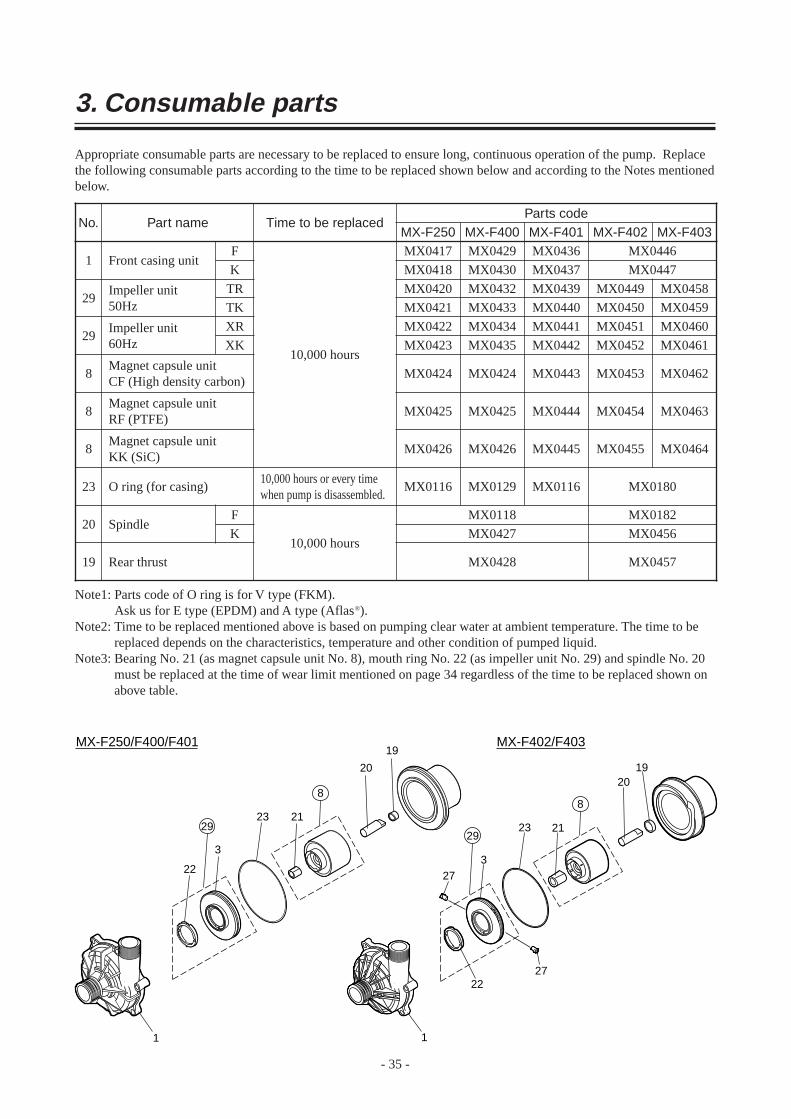
3. Consumable parts
Appropriate consumable parts are necessary to be replaced to ensure long, continuous operation of the pump. Replacethe following consumable parts according to the time to be replaced shown below and according to the Notes mentionedbelow.
MX-F250 MX-F400
Front casing unitMX0417 MX0429
Rear thrust
Impeller unit50Hz
MX0420 MX0432
Impeller unit60Hz
MX0422 MX0434
Magnet capsule unitCF (High density carbon)
MX0424 MX0424
Magnet capsule unitRF (PTFE)
MX0425 MX0425
Magnet capsule unitKK (SiC)
MX0426 MX0426
O ring (for casing) MX0116 MX0129 MX0180
Spindle
10,000 hours
MX-F401 MX-F402 MX-F403MX0436 MX0446
MX0439 MX0449 MX0458
MX0441 MX0451 MX0460
MX0443 MX0453 MX0462
MX0444 MX0454 MX0463
MX0445 MX0455 MX0464
MX0116
MX0182
MX0457
Note1: Parts code of O ring is for V type (FKM).Ask us for E type (EPDM) and A type (Aflas®).
Note2: Time to be replaced mentioned above is based on pumping clear water at ambient temperature. The time to bereplaced depends on the characteristics, temperature and other condition of pumped liquid.
Note3: Bearing No. 21 (as magnet capsule unit No. 8), mouth ring No. 22 (as impeller unit No. 29) and spindle No. 20must be replaced at the time of wear limit mentioned on page 34 regardless of the time to be replaced shown onabove table.
F
TR
XR
F
K MX0418 MX0430 MX0437 MX0447
TK MX0421 MX0433 MX0440 MX0450 MX0459
XK MX0423 MX0435 MX0442 MX0452 MX0461
K MX0456
1
29
29
20
8
8
8
23
19
10,000 hours
10,000 hours or every timewhen pump is disassembled.
MX0118
MX0427
MX0428
No. Part name Time to be replacedParts code
1
23 21
20
19
22
3
8
29
1
23 21
2019
2227
273
8
29
MX-F250/F400/F401 MX-F402/F403

4. Disassembling and assembling
Warning
Wear protectors
Hazardous liquids such as chemical liquids may harm your eyes or skin if you touch them directly or they are
splashed. When you do the works, wear protectors (mask, goggles, gloves etc.).
Turn off power
To avoid electrical shock, switch off the power to stop pump and equipment when works are done.
Precautions when disassembling and assembling pump* When power wires to motor are removed, mark on each wire so that the wires can be connected correctly not to rotate in
reverse when they are connected again.
* Do not disassemble the pump beyond the extent shown on this manual.
* Fully close suction and discharge sides valves before the works are done and clean pump inside.
* The magnet force used in the pump are strong. Pay attention for your fingers not to be pinched on disassembling and
assembling of pump. Pay attention for iron pieces or powder not to be attracted by the magnets.
* Do not put the electronic devices which dislike magnetic field near to the magnets.
- 36 -

4.1 Disassembling1) Remove hex. socket head bolts to remove a front
casing from a motor bracket and evacuate the casing
of residual liquid and clean it.
2) Pull out an impeller and a magnet capsule. Pay
attention for your fingers not to be pinched.
3) When the impeller is removed from the magnet
capsule, take following procedure paying attention
not to scratch the parts.
a. In case of MX-F250-F401
Hold the magnet capsule by hand and slightly tap the
back side of impeller by plastics hammer to remove
it from magnet capsule. If it is hard to be removed,
do not remove them by force but put them in hot
water (approx. 90 deg. C) for five minutes. Take
care for your fingers not to be burnt by hot water.
- 37 -

b. In case of MX-F402 and F403
Turn the lock pin counter clockwise direction by 90
degree using a minus screw driver and then push it
out to inside. If it is hard to push it out, slightly tap
the end of driver handle. If the screw driver can not
be used because the groove of pin was crushed, turn
the pin from inside of magnet capsule using hex.
wrench. In this case pay attention to turn the wrench
clockwise. The lock pin will be damaged if it is
turned in reverse direction. After the pin was turned,
push it out from outside using a bar or like.
After two lock pins are removed, remove the
impeller from the magnet capsule by slightly tapping
the periphery of impeller with plastic hammer. If it is
hard to remove, warm it with hot water (approx. 90
deg. C) for five minutes and remove it by slightly
tapping it as above. Pay attention not to burn
yourself.
Impeller can not be separated from magnet capsule
unless lock pin is removed. The parts are broken if
impeller is removed by force.
4) To remove a rear casing, insert a minus screw driver
to the periphery of rear casing and slightly pull
forward the screw driver. Pay attention not to scratch
an O ring.
- 38 -

Through hole
End surface of press-fit part
U shaped hole
Check tosee no gap.
4.2 Assembling1) Mount the impeller to the magnet capsule.
a. In case of MX-F250-F401.
Fit together the projected and recessed parts of
magnet capsule and impeller and push the impeller to
the bottom. Put a through hole of magnet
capsule and U shaped hole of impeller together.
If you find no gap between the end surface of
impeller and bearing end surface, this means
the impeller was securely press fit into the
magnet capsule. If it is hard to press fit them, do
not put them by force but warm the magnet capsule
only by putting it in hot water (approx. 90 deg. C) for
five minutes. Take care for your fingers not to be
burnt by hot water.
b. In case of MX-F402 and F403
Mating part of magnet capsule has two holes of a
bigger hole for lock pin (stepped hole of outside 6
mm dia. and inside 12 mm dia.) and a smaller hole (3
mm dia.) for cooling purpose. U-shape hole of
impeller and smaller hole (3 mm dia.) of magnet
capsule are for cooling purpose. Insert the impeller
into the magnet capsule slowly by positioning the
two holes together. If it is hard to insert them, warm
the magnet capsule only with hot water (approx. 90
deg. C) for five minutes.
- 39 -

CautionBracketSpacer
Impeller
After the impeller is inserted (press-fit), insert the
lock pin till the first step from inside and then,
strongly holding it by finger from inside, tighten the
pin by turning it clockwise by 90 degrees from
outside with minus screw driver. You will feel the
snap action when it is fixed securely. Mount two
lock pins at symmetric position.
If the groove for minus screw driver is deformed and
can not be used, the pin can be fixed from inside
with 4mm hex. wrench. In this case pay attention to
turn the wrench counter clockwise direction. The
lock pin may be broken if it is turned in reverse.
2) Put the magnet capsule with impeller into the rear
casing slowly. Check if iron pieces or other foreign
matters do not adhere to the magnet capsule
3) Mount the rear casing with magnet capsule to the
bracket.
Magnet force is very strong. Apply plastics or wooden spacers between the rear casing and bracket not to pinch your fingers.
- 40 -

- 41 -
4) Put O ring to the front casing. Check to see if there is no dust or scratch on it. Pay attention for the O ring not to be
forgotten to be put or not to be bitten. For the models MX-F250 and F401, fit together the recessed and
projected portions of rear casing and front casing when the front casing is mounted to the rear casing.
Two each recess and projection for MX-F402 and F403.
Rear casing
Recess for positionning
Projection for positionning
Front casing
5) Mount the front casing to the motor bracket.
Tighten the mounting bolts diagonally and evenly. Tightening torque is shown below.
Model Bolt tightening torque
MX-F402, F403 14.7 N·m
MX-F250, F400, F401 11.8 N·m

Read this manual before use of product
IWAKI Magnetic Drive Pump
MX-F250~F403
Instruction Manual (Europe Edition)
T502 '03/02
( )Country codes
IWAKI CO.,LTD. 6-6 Kanda-Sudacho 2-chome Chiyoda-ku Tokyo 101-8558 JapanTEL:(81)3 3254 2935 FAX:3 3252 8892(http://www.iwakipumps.jp)
Germany : IWAKI EUROPE GmbHItaly : IWAKI Italia S.R.L.Denmark : IWAKI Pumper A/SSweden : IWAKI Sverige ABFinland : IWAKI Suomi OyNorway : IWAKI Norge ASFrance : IWAKI France S.A.U.K. : IWAKI PUMPS (UK) LTDSwitzerland : IWAKI (Schweiz) AGAustria : IWAKI (Austria) GmbHHolland : IWAKI Holland B.V.Spain : IWAKI Iberica Pumps,S.A.Belgium : IWAKI Belgium n.v.
TEL : (49)2154 9254 0 FAX : 2154 1028TEL : (39)02 990 3931 FAX : 02 990 42888TEL : (45)48 24 2345 FAX : 48 24 2346TEL : (46)8 511 72900 FAX : 8 511 72922TEL : (358)9 2742714 FAX : 9 2742715TEL : (47)66 81 16 60 FAX : 66 81 16 61TEL : (33)1 69 63 33 70 FAX : 1 64 49 92 73TEL : (44)1743 231363 FAX : 1743 366507TEL : (41)32 3235024 FAX : 32 3226084TEL : (43)2236 33469 FAX : 2236 33469TEL : (31)297 241121 FAX : 297 273902TEL : (34)943 630030 FAX : 943 628799TEL : (32)1430 7007 FAX : 1430 7008
U.S.A. : IWAKI WALCHEM CorporationAustralia : IWAKI Pumps Australia Pty. Ltd.Singapore : IWAKI Singapore Pte. Ltd.Indonesia : IWAKI Singapore (Indonesia Branch)Malaysia : IWAKIm Sdn. Bhd.Taiwan : IWAKI Pumps Taiwan Co., Ltd.Thailand : IWAKI (Thailand) Co.,Ltd.Hong Kong : IWAKI Pumps Co., Ltd.China : GFTZ IWAKI Engineering & Trading Co., Ltd.China : IWAKI Pumps Co., Ltd. (Beijing office)China : IWAKI Pumps (Shanghai) Co., Ltd.Philippines : IWAKI Chemical Pumps Philippines, Inc.Korea : IWAKI Korea Co.,Ltd.
TEL : (1)508 429 1440 FAX : 508 429 1386TEL : (61)2 9899 2411 FAX : 2 9899 2421TEL : (65)763 2744 FAX : 763 2372TEL : (62)21 690 6607 FAX : 21 690 6612TEL : (60)3 7803 8807 FAX : 3 7803 4800TEL : (886)2 8227 6900 FAX : 2 8227 6818TEL : (66)2 320 1303 FAX : 2 322 2477TEL : (852)2 607 1168 FAX : 2 607 1000TEL : (86)20 8435 0603 FAX : 20 8435 9181TEL : (86)10 6442 7713 FAX : 10 6442 7712TEL : (86)21 6272 7502 FAX : 21 6272 6929TEL : (63)2 888 0245 FAX : 2 843 3096TEL : (82)2 3474 0523 FAX : 2 3474 0221