IVTM Tyre Pressure Monitoring for Commercial · PDF fileTyre Pressure Monitoring for...
48
IVTM Tyre Pressure Monitoring for Commercial Vehicles
Transcript of IVTM Tyre Pressure Monitoring for Commercial · PDF fileTyre Pressure Monitoring for...

IVTM
Tyre Pressure Monitoring for Commercial Vehicles

IVTM Tyre Pressure Monitoring for Commercial Vehicles
System Description
Edition 5
This publication is not subject to any update service. You will find the latest version in INFORM www.wabco-auto.com
© 2008 WABCO
The right of amendment is reserved.Version 1/05.2008(en)
815 010 045 3

IVTM Table of Contents
4
1 Important notes 6 1.1 General Information 6 1.2 General safety instructions 6 1.3 Symbols used 7
2 Introduction 8 2.1 IVTM prevents tire blow-outs 8 2.2 IVTM reduces costs 8
3 System Description 10 3.1 IVTM Basic Functions 10 3.2 IVTM at trailer-towing operation 11 3.3 Configuration for bus and towing vehicle 11 3.4 Configuration for trailers 12 3.5 Certificates 17
4 Components 18 4.1 Wheel module 18 4.2 Electronic Control Unit (ECU) 21 4.3 The display 23 4.4 Connecting tube 23 4.5 Connecting cable 25
5 Operation 27 5.1 Warning signals 27 5.2 Switch on of ignition 27 5.3 Checking pressure values 28 5.4 Display of faults 29 5.5 Adjusting tyre pressures 30 5.6 Display of System Errors 30 5.7 Operation via SmartBoard 32
6 Installation 33 6.1 Mounting the wheel modules 33 6.2 Mounting the ECU in bus / towing vehicle 36 6.3 Wiring in towing vehicle/bus 37 6.4 Mounting the ECU in the trailer 37 6.5 Wiring in trailer 38 6.6 End of line test 39

Table of Contents
IVTM
5
7 Workshop instructions 40 7.1 Diagnostics 40 7.2 Wheel Changes 41 7.3 Replacing PA tubes 42 7.4 Replacing hose connections 43 7.5 Replacing wheel module I with wheel module II 43 7.6 Creeping pressure loss 43 7.7 No reception of the wheel module 44 7.8 Disposal 46
1 IVTM
Important notes
6
1 Important notes
1.1 General Information
This publication is directed at trained service technicians employed at workshops for commercial vehicles.
Intended application The IVTM System is only intended for monitoring the tyre pressure of commercial vehicles.
Before you begin with maintenance, repair, replacing a part, etc., carefully read all
the safety instructions as well as the repair and maintenance instructions included this publication. These instructions must be observed to avoid personal injury or material loss. WABCO only guarantees the reliability and performance of its products and sys-tems if all instructions, notes and safety instructions are observed.
FCC Notice This device consists of wheel module 960 73X XXX X (SA4-WM730) and Elec-tronic Control Unit 446 220 XXX X (SA4-ECU220)
This device complies with Part 15 of the FCC Rules. Operation is subject to the fol-lowing two conditions:
(1) this device may not cause harmful interference, and
(2) this device must accept any interference received, including inter-ference that may cause undesired operation.
Changes or modifications not expressly approved by the party responsible for the compliance could void the user's authority to operate the equipment.
1.2 General safety instructions
Before you perform any work on the vehicle (repair, maintenance, replacing parts, etc.), you must ensure the following:
WARNING
Severe damage to property and injuries to health may result due to improper assembly or repair work. – Only trained and qualified personnel may perform repairs on the vehicle. – Always follow the specifications and instructions of the vehicle manufacturer. – Always comply with the Company and national accident prevention guidelines
and Health and Safety regulations. – Wear suitable protective clothing as the situation requires. – Ensure that the workplace is dry and provided with sufficient lighting.

IVTM 1Important notes
7
1.3 Symbols used
DANGER
Warns of an imminent hazard situation which can cause serious personal injury or death if the safety instruction is not observed.
WARNING
Warns of a possible hazard situation which can cause serious personal injury or death if the safety instruction is not observed.
CAUTION
Warns of a possible hazard situation which can cause light or minor personal injury if the safety instruction is not observed.
Marks important instructions, information or tips that you should always observe.
• List or action step – Step
Result of an action

2 IVTM
Introduction
8
2 Introduction
In this chapter, you will be provided with an overview of the advantages that the IVTM offers.
2.1 IVTM prevents tire blow-outs
IVTM stands for Integrated Vehicle Tyre Pressure Monitoring. The system is con-tinuously monitoring tyre pressure on all wheels by means of pressure sensors. In case of critical condition, the driver is warned in time via display in the towing vehi-cle's driver's cab. Since around 85 % of all punctures are caused by driving with wrong air pressure or creeping pressure loss while in motion, risk of tyre burst can be reduced down to 15 % thanks to IVTM.
fig. 2-1: Root causes for roadside emergencies (source: ADAC 2006)
A Tyres 28.1% B Electrics 24.4% C Engine 19.4% D Others 28.1%
2.2 IVTM reduces costs
By selecting the right tyres and having them properly maintained, substantial sav-ings can be achieved per vehicle each year. Maintaining correct inflation pressure for instance: In practice, about every second tyre is run at an air pressure falling below 10 percent of the specified one. Also 20 % under nominal pressure is not unusual, and this will reduce tyre mileage by as much as 20 %. This will push up fuel consumption in each case. By contrast, careful pressure checks will generate payroll cost of round about 30 minutes per vehicle but IVTM zeroes this expenditure item. So IVTM minimises cost and makes a great contribution to safety on our roads. IVTM allows employment of Super Singles instead of twin wheels. IVTM can be easily retrofitted.
Return of Investment Calculator Using our Return of Investment Calculator on our homepage (www.wabco-auto.com), you are able to calculate use your IVTM offers within a few stages. You

IVTM 2Introduction
9
can either enter your individual application data or use standard profiles for deter-mining which savings you are able to achieve using the IVTM.
fig. 2-2: Mileage vs air pressure dependency
A Tyre pressure B Service life reduction C Tyre pressure too low D Tyre pressure too high
fig. 2-3: Consumption vs air pressure dependency
A Tyre pressure B Fuel consumption C Tyre pressure too low D Tyre pressure too high

3 IVTM
System Description
10
3 System Description
This chapter describes the mode of operation of the IVTMs. Furthermore, you will also obtain information concerning technical reports for installing and retrofitting.
3.1 IVTM Basic Functions
fig. 3-1: Solo system
A Electronic Control Unit (ECU) B Wheel module C Display
Each wheel continuously transmits actual tyre pressure to a central electronic con-trol unit (ECU). The signals of all wheels are evaluated there and the information is conveyed to a display in the driver's cab.
Measuring Wheel modules measure the air pressures on the conventional valves every 15 minutes and transmit them to the ECU. If pressure was changing critically then the wheel module would sent the values in shorter periods.
Evaluating Evaluation is far more than just comparing a current pressure value with an al-lowed one and sending a warning message on falling below. The ECU discrimi-nates a real problem situation from usual pressure fluctuations during vehicle op-eration also on bad road conditions or uneven load. In the event that an irregularity occurs then this fact would not only be reported on the display but the wheel in question would be exactly indicated too. An IVTM ECU can receive and process data from up to 16 wheel modules each and further ECUs. Dual tyres will each be individually fitted with sensors. Sensor pressure range is between 2 and 14 bar corresponding to nominal tyre pressures from 3 to 10.5 bars.

IVTM 3System Description
11
Displays WABCO is offering a driver's display for indicating warning messages and tyre pressure retrievals. Data, alternatively, can also be transmitted to an integrated display on certain vehicles (within scope of original equipment only). Detailed de-scription of display functionality is given in chapter 5.
IVTM, and therefore TPI, cannot announce sudden grave tyre damages caused by
external effects.
3.2 IVTM at trailer-towing operation
Operating mode Initially, the IVTM system on the trailers will work self-sufficiently if there is a power supply. In order to display tyre pressure and trailer warnings to the driver during driving, however, it is necessary to install IVTM to both parts of vehicle, which means one control unit to the trailer and one unit to the motor vehicle. Any vehicle equipped with IVTM could be connected to any trailer equipped with IVTM.
Variants The IVTM for trailers vehicles can be operated using the WABCO SmartBoard as well as for stand-alone versions. Pressure information, in connection with WABCO TCE or EBS, can be transferred to the towing vehicle's CAN bus via standard CAN data connection according to ISO 11992 (only in connection with appropriately prepared towing vehicle).
Automatic trailer recognition Control unit of vehicle identifies control unit of trailer automatically: The stop light is enabled on towing vehicle and trailer when hitting the brake. The trailer ECU radios a signal with this voltage pulse that is expected by the towing vehicle's ECU that instant. The towing vehicle thus clearly detects that the trailer is belonging to the tractor/trailer combination and subsequently transmits trailer ECU messages to the display. As trailers are usually not permanently powered, it is possible that due to the fre-quency of wheel modules transmission the tyre pressure data for all the wheels of the trailer is not available in the display for up to 15 minutes after starting the drive.
3.3 Configuration for bus and towing vehicle
This chapter explains which components you require for your vehicle. Selection of IVTM components depends on vehicle type, type and number of wheels and type of systems connected to IVTM but not from vehicular system volt-age.
ECU Lorries, buses or articulated buses are equipped with the ECU 446 220 012 0.
Display VTM display 446 221 000 0 is used for the retrofitting of the display and operation devices. Original equipment, however, will often address a central computer via CAN with the latter controlling indication of the integrated dashboard-mounted dis-play.

3 IVTM
System Description
12
Wheel modules Select wheel modules and counterweights according to their axle configuration. The table contains components for three vehicle types exemplarily. Further de-tailed information for the components can be obtained in the chapter "Compo-nents" (see chapter 4, page 18)
Order Number Component Note 4x2 6x2 Articulated bus 6x2
446 220 012 0 ECU Communication with trailer ECU / warning lamps
1 1 1
446 221 000 0 Display 1 1 1
894 607 390 0 Wiring harness Cable set, 7-pin optional 894 607 295 0 (5-pin, no trailer-towing operation)
1 1 1
960 731 051 0 L shape wheel module
for the front axle, rim 22.5", 10 holes
2 4 2
960 731 031 0 Wheel module for rear axle, rim 22.5", 10 holes
4 4 8
960 730 822 0 Weight coun-terbalance
Balance weight for front axle wheel module
2 4 2
960 731 802 0 PA tube for front axle wheel module, L-shape
2 4 2
960 731 803 0 PA tube for rear axle wheel module, outside
2 2 4
960 731 804 0 PA tube for rear axle wheel module, inside
2 2 4
Table: 3-1: Components for bus / towing vehicle
Operation via CAN bus Provided the trailer is equipped appropriately, data exchange can also be made via CAN bus besides wireless connection between towing vehicle and trailer. Towing vehicle ECU needs to be connected to vehicular CAN Bus for this purpose too.
Circuit diagrams Like component quotation drawings, detailed wiring diagrams may be retrieved from product database INFORM. Enter wiring diagram product number for opening the file: • 841 801 970 0: Solobus • 841 801 971 0: Articulated bus • 841 801 972 0: Articulated truck / truck
3.4 Configuration for trailers
Transmission types Trailer and towing vehicle must be equipped with IVTM for displaying trailer IVTM data in the diver's cab.

IVTM 3System Description
13
Alternatively, trailer data can display in the towing vehicle only then when it is equipped with an integrated display. When the trailer is also equipped with TCE or TEBS then data transfer can be made to the towing vehicle central computer via CAN. The following illustration compares both transmission types, wireless connec-tion and CAN bus, with each other.
fig. 3-2: Data transfer wireless connection (top) and CAN
A IVTM display B Wheel modules C IVTM-ECU D Wireless connection E IVTM Trailer ECU F Integrated display G Central computer H EBS/TCE
Stand-alone trailer towing operation If the trailer should be independently equipped with IVTM, then the pressure re-lease can be carried out via telemetrics or the vehicles own display. When using the IVTM display, it requires a special box for splash protection or another pro-tected attachment location. The WABCO SmartBoard can be installed as an alter-native. The driver cannot receive fault messages without IVTM support while the towing vehicle is in motion.
IVTM with several trailers Equipment of tractor/trailer combinations with more than one trailer is possible. Tractor/trailer combinations with two trailers can be made with wireless connec-tions; roadtrains need CAN bus connection with special ECUs. Please contact your WABCO partner for such adaptation.
IVTM with TEBS D, TEBS E or TCE Installation in a vehicle with TEBS D, TEBS E or TCE is simple because this merely has to be plugged into pre-assembled cables. Other systems would require open wiring that needs to be enclosed by protective housing. Observe the current installation instructions for the control unit of the ABS / EBS in the WABCO product database INFORM (www.wabco-auto.com) and / or those of the vehicle manufacturer.

3 IVTM
System Description
14
The wiring diagrams illustrated in the following table in excerpt form can be re-
trieved from database INFORM.
Wiring diagrams for trailers
Wiring diagram 841 801 943 : Trailer ABS VCS Cable position 8 (449 344 ... .) is opened and con-nected to cable position 3 (449 674 273 0) and a line to the stop light in a wiring box.
Wiring diagram 841 801 946 0: Trailer ABS VCS II Cable position 8 (449 336 ... .) is opened and con-nected to cable position 3 (449 674 273 0), cable position 11 (449 621 ... .) and a line to the stop light in a wiring box.
Wiring diagram 841 801 941 0: Trailer EBS with CAN connection Cable position 8 (449 614 ... .) is opened and con-nected to cable position 3 (449 674 273 0) and a line to the stop light in a wiring box. The ISS output must not be used and needs to be set to 0 km/h.

IVTM 3System Description
15
Wiring diagram 841 801 945 0: Trailer EBS D with CAN Connection is made with cable position 3 (449 377 ... 0 / 449 378 ... 0). The ISS output must not be used and needs to be set to 0 km/h. IVTM diagnostic through diagnostic cable 446 300 329 2 via TEBS diagnostic interface.
Trailer TCE Connection like on Trailer EBS D with CAN but with cable 449 302 ... 0.
Wiring like 841 801 945 0
Wiring diagram 841 801 940 0: Trailer ECAS Cable position 3 (449 674 273 0) is introduced into bottom box of ECAS-ECU and connected there. One cable to stop lamp (position 7) is installed addition-ally. You need screwed cable glands (PG 11: 894 130 312 2) for two cables.
Wiring diagram 841 801 944 0: Vario-C Cable position 3 (449 674 273 0) is introduced into bottom box of ABS-ECU and connected there. One cable to stop lamp (position 7) is installed addition-ally. You need screwed cable glands (PG 11: 894 130 312 2) for two cables.

3 IVTM
System Description
16
Wiring diagram 841 801 942 0: Trailer EBS and ELM Cable position 8 (449 344 ... .) is opened and con-nected to cable position 3 (449 674 273 0) and a line to the stop light in a wiring box.
Wiring diagram 841 801 913 0: Trailer EBS D and SmartBoard (from year of construction 2004) SmartBoard and IVTM are connected to the Trailer EBS D modulator on port IN/OUT2. CAN 2 must be activated (activation via diagnostic software). 1 Trailer EBS D Modulator 480 102 014 0 2 Line of cables 449 377 ... 0 3 SmartBoard 446 192 110 0 4 IVTM 5 Distribution box
Wiring diagram 841 802 155 0 Trailer EBS E IVTM is connected to sub-systems using cable (449 911 ... .).

IVTM 3System Description
17
Wiring diagram 841 802 155 0 TEBS E with SmartBoard IVTM and SmartBoard are connected to sub-systems using cable (449 916 ... .).
Table: 3-2: Components for trailers
3.5 Certificates
Certificates for mounting and additional mounting of IVTM are available, which sig-nificantly facilitate approval of vehicle registration papers. The test reports are not part of this brochure but you may request them from WABCO or open them in product database INFORM on the Internet (www.wabco-auto.com, index word: "report"). Following certificates are stored there: • Expertise TÜH ATC TB 2002-108.00 • Part certificate of TÜH ATC - TB 2003-023.00 • Type approval 94/9/EG CE 0032, TÜV03 ATEXxxxx • Operating range: εx II 2G EEx ib IIC T4

4 IVTM
Components
18
4 Components
This component description details the properties of basic components. You find further details such as dimensions via product number in product database IN-FORM on the Internet (www.wabco-auto.com).
4.1 Wheel module
CAUTION
Risk due to incorrect handling – Any changes of manipulation to the wheel module of any type, especially at-
tempts made to change the battery will destroy the device and may lead to inju-ries. For this purpose, do not unscrew or loosen the module from the bracket.
fig. 4-1: Wheel module with connecting hose
The wheel module consists of a compound-filled plastic unit comprising a pressure sensor, an evaluation circuit, a radio transmitter and a lithium battery. Battery life under normal operating conditions is minimum 6.5 years. If the battery is dead the module would not transmit any longer and needs to be replaced with a new one. The wheel module is mounted to the rim by the standard lug nuts and is connected to valve via a PA tube. The result is an easy installation. You will not need to re-move the tyre from the rim when retrofitting.
Data transfer Wireless transmission is made by 433 MHz signal. If pressure is constant, meas-ured values are transmitted every 18 minutes (9 minutes with versions that do not have acceleration sensor), if pressure is changing, frequency of data transfers is faster.
IVTM can be interrupted in its function if other devices or systems in the vicinity are
also transmitting in the area of 433 MHz. This can be walkie-talkies, radio remote controls (e.g. for door actuation, cranes, fork lift), insufficient unshielded electrical actuation with high power or other radio transmitters. When IVTM system is re-moved from the influencing area, the function is guaranteed again.
Depending on rim crank, use of the normal module according to Figure 4-1 or the so-called L-shape or T-shape version is recommended. For details see Table 4-1 and also chapter Configuration (see chapter 3.3, page 11).

IVTM 4Components
19
Application WABCO number Hole, wheel bolt
Pitch cir-cle diame-ter
Elbow Figure
Trailer: Independent wheel (no Super-Single)
960 731 011 0 26 mm 335 mm 0°
Trailer: Independent wheel (no Super-Single), 20° for special purposes (e.g. Iveco)
960 731 013 0 23 mm 335 mm 0°
Trailer: Independent wheel (no Super-Single), 23 mm pitch circle diameter
960 731 017 0 23 mm 335 mm 0°
Trailer: Independent wheel (no Super-Single)
960 731 021 0 32 mm 335 mm 0°
Twin tyres, Super-Single 960 731 031 0 26 mm 335 mm 70°
Twin tyres, Super-Single 960 731 041 0 32 mm 335 mm 70°
Towing vehicle: Front axle, load axle 960 731 051 0 26 mm 335 mm 60°
Towing vehicle: Front axle, load axle 960 731 053 0 26 mm 335 mm 0°

4 IVTM
Components
20
Application WABCO number Hole, wheel bolt
Pitch cir-cle diame-ter
Elbow Figure
Towing vehicle: Front axle, load axle 960 731 061 0 32 mm 335 mm 33°
Towing vehicle: Front axle, load axle 960 731 063 0 26 mm 335 mm 33°
Twin tyres, Super-Single 960 731 073 0 26 mm 285,75 mm 70°
Towing vehicle: Front axle, load axle 960 731 075 0 26 mm 285,75 mm 33°
Twin tyres, Super-Single 960 731 081 0 26 mm 225 mm 70°
Counterweight for L-shape wheel module
960 730 882 2 960 730 828 2
26 mm 32 mm
0°
Counterweight independent wheels 960 730 820 4 960 730 825 4
26 mm 32 mm
0°
Table: 4-1: Wheel modules and counterweights

IVTM 4Components
21
With twin wheels and Super Single rims, problems may occur with the radio trans-
mission due to the immersion depth. To ensure the quality of the reception, wheel modules with the T-shape should be used (960 731 031 0 or 960 731 041 0).
Counter weight The wheel module must not disrupt wheel balance; therefore, the counterweight is mounted on the opposite side according to Figure 4-2.
fig. 4-2: Module with counterweight
fig. 4-3: Module for twin wheels
Axles without dual tyres do not need counterweight. In this case, the wheel module of one wheel serves as counterweight for the wheel module of the other wheel. They are mounted opposite.
ID code Special identification code of each wheel allows unique assignment of modules to particular wheels. The wheel module will "report" to ECU using this code. This will exclude pressure signals from other vehicles being sent to this system. The code is determined when the module is manufactured and cannot be changed. This num-ber is imprinted on the wheel module when commissioning.
Assignment between wheel and wheel module must be absolutely maintained dur-
ing tyre-change procedure. If tyres were confused, IVTM could not set off required alarm when a wheel with low pressure has been wrongly assigned to an axle on which this pressure is still permissible.
Identification code assignment to a wheel is determined by the diagnosis software on commissioning (see page 39).
4.2 Electronic Control Unit (ECU)
fig. 4-4: ECU

4 IVTM
Components
22
Mode of function The ECU recognises all changes from programmed nominal values of tyre pres-sure are immediately by combined comparison with threshold pressure values and pressure changes. Incorrect values of tyre pressures are already displayed before departure (if ECU is permanently powered). The system may be extended up to 12 wheel modules for truck / bus and for trail-ers up to 16 wheel modules. After system installation, commissioning by PC diag-nostic software must be performed. Any faults occurring during operation are stored in the electronic unit for diagnostic purposes.
Design Three standard versions of the electronic control unit (ECU) are employed: • Towing vehicle and bus: 446 220 012 0 • Trailer: 446 220 013 0 • Trailer Train: 446 220 014 0 (can be cascaded up to 5 times with 16 modules
each) Electronics essentially differ by radio communication signal structure and CAN bus (ID) connection. External distinguishing mark by type label only. Further ECU types are tailored to specific customer requests and have other pin assignments. All ECUs are suitable for 12 or 24 volt operation and can be mounted on the vehi-cle frame.
Software change ECUs produced after calendar week 43/07 already have new software installed. The setting range of the reference pressure has been reduced down to 3 to 10.5 bars. The software change allows the reference pressure to be set within cer-tain tolerances on-board. Furthermore, it is also possible to measure the signal quality of the radio contact to the wheel modules and to display them using the di-agnostic software. The new software allows different reference pressures to be set per axle.
Radio transmission The ECU is mounted to chassis in the central part of the vehicle, so that perfect ra-dio contact with all wheel modules and connection between vehicle ECU and trailer ECU is ensured. You should use special brackets for good radio contact.
fig. 4-5: Bracket 960 901 050 4
Radio contact is provided by an antenna integrated in the control unit housing that guarantees pressure signal reception from all wheel modules even under the most difficult operating conditions.
IVTM 4Components
23
4.3 The display
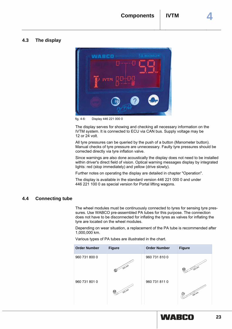
fig. 4-6: Display 446 221 000 0
The display serves for showing and checking all necessary information on the IVTM system. It is connected to ECU via CAN bus. Supply voltage may be 12 or 24 volt. All tyre pressures can be queried by the push of a button (Manometer button). Manual checks of tyre pressure are unnecessary. Faulty tyre pressures should be corrected directly via tyre inflation valve. Since warnings are also done acoustically the display does not need to be installed within driver's direct field of vision. Optical warning messages display by integrated lights: red (stop immediately) and yellow (drive slowly). Further notes on operating the display are detailed in chapter "Operation". The display is available in the standard version 446 221 000 0 and under 446 221 100 0 as special version for Portal lifting wagons.
4.4 Connecting tube
The wheel modules must be continuously connected to tyres for sensing tyre pres-sures. Use WABCO pre-assembled PA tubes for this purpose. The connection does not have to be disconnected for inflating the tyres as valves for inflating the tyre are located on the wheel modules. Depending on wear situation, a replacement of the PA tube is recommended after 1,000,000 km. Various types of PA tubes are illustrated in the chart.
Order Number Figure Order Number Figure
960 731 800 0 960 731 810 0
960 731 801 0 960 731 811 0

4 IVTM
Components
24
Order Number Figure Order Number Figure
960 731 802 0 960 731 812 0
960 731 803 0 960 731 813 0
960 731 804 0 960 731 814 0
960 731 808 0 960 731 816 0
960 731 809 0
Table: 4-2: Connecting tube
Check PA tubes frequently for damages and replace them if necessary.
Replace defective hose connections with PA tubes. At the same time, install a new wheel module type II. (see chapter 7.5 "Replacing wheel module I with wheel mod-ule II", page 43)
Vehicles with OE equipment
Rubber hoses can be fitted in vehicles installed with OE equipment. Before replac-ing the hoses, observe the release notes of the manufacturer.
Valve extension
Do not use valve extensions made of plastic!
Do not use plastic valve extensions. These will not remain tight under permanently existing pressure! Use flexible valve extensions with tightening clamps (e.g. alligator) or WABCO valve extensions 960 731 805 0 instead.
IVTM and tyre sealing compound of the WABCO Tire Premium Seal
The use of the WABCO Tire Premium Seal tyre sealing compound is only possible when valve extensions made of brass are used. Any other valve extensions must be removed before the tyre can be inflated with the tyre sealing compound.
IVTM 4Components
25
4.5 Connecting cable
Connection IVTM to vehicle wiring on towing vehicle / bus performed in two sec-tions: The section step comprises connection of ECU to distribution element adja-cent to driver's workplace. This section is splash-proof allowing external installation on the vehicle. The second section is a cable set designed for interior installation only and distribution to display, diagnosis interface and, using the free cable ends, to the terminals of vehicle wiring from coupling of first cable is made from here.
Basic wiring principle for towing vehicle / bus is displayed in the following illustra-tion.
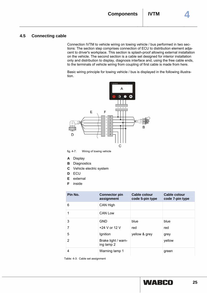
fig. 4-7: Wiring of towing vehicle
A Display B Diagnostics C Vehicle electric system D ECU E external F inside
Pin No. Connector pin
assignment Cable colour code 5-pin type
Cable colour code 7-pin type
6 CAN High
1 CAN Low
3 GND blue blue
7 +24 V or 12 V red red
5 Ignition yellow & grey grey
2 Brake light / warn-ing lamp 2
yellow
4 Warning lamp 1 green
Table: 4-3: Cable set assignment

4 IVTM
Components
26
Connection to +12 V/24 V and ignition to be fused through 5 ampere fuses. Since
IVTM has low current consumption an existing fused circuit can be used.
Cable set towing vehicle, 7-pin 7-pin wiring according to cable set 894 607 390 0 is supposed to be used as shown on Figure 4-7. Pin assignment on the connecting plugs corresponds to the 5-pin variant. In addition, either connection to stop lamp (for synchronising with trailer ECU) and warning lamp or connection of two warning lamps is possible.
Cable set towing vehicle, 5-pin Simpler wiring is intended as 5-pin variant for bus retrofitting: 894 607 295 0. Em-ployment of this wiring allows driving of warning lamps inside display or via CAN respectively but not separate warning lamps on dashboard.
Cable set, trailer Chapter "Configuration" details different wiring to CAN capable systems (TEBS or TCE). Cable set 449 674 273 0 should be used according to Figure 4-8, if data transmission is made through wireless connection only.
fig. 4-8: Trailer wiring
A ECU B Brown: Ground C Red: +12 V/24 V D White: Brake light E Diagnostics
Diagnostic cable Cable 446 300 348 0 connects the diagnostic connector on the vehicle with the di-agnostic interface during diagnosis. Further information see chapter "Diagnosis".
IVTM 5Operation
27
5 Operation
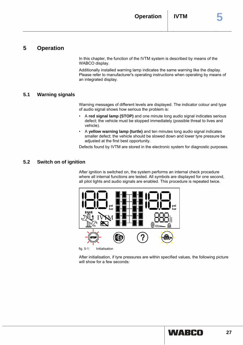
In this chapter, the function of the IVTM system is described by means of the WABCO display. Additionally installed warning lamp indicates the same warning like the display. Please refer to manufacturer's operating instructions when operating by means of an integrated display.
5.1 Warning signals
Warning messages of different levels are displayed. The indicator colour and type of audio signal shows how serious the problem is: • A red signal lamp (STOP) and one minute long audio signal indicates serious
defect; the vehicle must be stopped immediately (possible threat to lives and vehicle).
• A yellow warning lamp (turtle) and ten minutes long audio signal indicates smaller defect; the vehicle should be slowed down and lower tyre pressure be adjusted at the first best opportunity.
Defects found by IVTM are stored in the electronic system for diagnostic purposes.
5.2 Switch on of ignition
After ignition is switched on, the system performs an internal check procedure where all internal functions are tested. All symbols are displayed for one second, all pilot lights and audio signals are enabled. This procedure is repeated twice.
fig. 5-1: Initialisation
After initialisation, if tyre pressures are within specified values, the following picture will show for a few seconds:

5 IVTM
Operation
28
fig. 5-2: System check
The display will change to normal mode if all pressures are OK.
fig. 5-3: Normal mode
5.3 Checking pressure values
Proceed as follows to display the pressure values of the individual tyres: – Push left button. The axle of which the pressures are displayed, is marked on
the display. Left pressure value on the display corresponds to left tyre in direc-tion of travel.
fig. 5-4: Requesting the pressure values
– Repeatedly push left button to display pressure values of further axles. Axles with twin tyres have their wheels represented outside and inside one after the other.
– Repeatedly push left button to display the axles of the towing vehicle as well the axles of the towing vehicle.

IVTM 5Operation
29
The display will switch back to normal mode if no button has been pushed for a
period of 20 seconds.
5.4 Display of faults
When the IVTM detects a fault, a yellow or red warning lamp illuminates. Proceed as follows to display the type of fault on the vehicle: – Push right button after lighting up of yellow or red warning lamp. The pressure
value of the conspicuous wheel will be indicated and the position on the vehicle is indicated by a flashing wheel icon.
If no current defect is found the system does not react to pressing the right button.
fig. 5-5: Display of faults
If the system warns about several tyres then the tyre having the most serious fault
is indicated first. Repeated pressing of right button will show further faults.
fig. 5-6: Creeping pressure loss
The individual fault types are shown in the following:

5 IVTM
Operation
30
Error Displayed Action
1. Extremely low pressure
Stop the vehicle immediately. Look for the cause. If necessary, also change the tyre.
2. Low pressure Reduce your driving speed. Adjust air pressure at the next opportunity.
3.Creeping pres-sure loss
Reduce your driving speed. Stop the vehicle at the next opportunity. Look for the cause of the pres-sure loss. If necessary, also change the tyre.
4. High pressure Reduce your speed to prevent-ing the tyre from bursting. Stop the vehicle at the next opportunity. Search for the cause of excess pressure (e.g. defective, over-heated brake). Adjust the tyre inflation pres-sure when the excess pressure is caused by cold tyres.
Table: 5-1: Fault type overview
5.5 Adjusting tyre pressures
Proceed as follows to adjust the tyre pressures on the vehicle:
Do not adjust tyre pressure with the ignition switch on - this may cause faulty warn-
ing messages on display.
– Turn off the ignition. – Adjust air pressure. – Switch on ignition again. If leakage warning has been active, reset on display and stored on diagnostic memory of the ECU.
5.6 Display of System Errors
If "IVTM" is represented crossed out then there are one or more system faults. System should be checked in the workshop.

IVTM 5Operation
31
No reception Marked wheel has not transmitted pressure value for over one hour. IVTM has stopped sending warning messages for this wheel, driver needs to check tyre pressures on the wheel manually.
fig. 5-7: No reception
Repair note With an older system, if the wheel module battery is exhausted. The wheel module must be replaced. – Replace the wheel module. – Start operating the new wheel module using diagnostic software by setting a
new ID in the parameters. If it is a newer system, and the radio connection between the wheel module and the ECU is disturbed. – Remove any possible dirt. – Select a better attachment location for the ECU. Further information see chapter "Workshop Hints".
System failure System faults are given if the display shows a crossed-out "IVTM" only. If IVTM has stopped sending warning messages for any wheel, driver needs to check tyre pressures on the wheel manually.
fig. 5-8: System error
Repair note – Check the supply voltage of the ground line. – Check the cable connections. – Carry out a system diagnosis.

5 IVTM
Operation
32
5.7 Operation via SmartBoard
IVTM can be operated via SmartBoard. With SmartBoard you actuate IVTM as Stand alone variant. Select the functional group Tyre pressure monitoring. The tyre pressures for the individual tyres, the desired tyre pressure, and the con-figuration is displayed in this functional group.
The key <Arrow right> is used to switch between the different tyres.
The tyre symbol flashes if the tyre pressure is too low. If the tyre has a fault, the warning LED and the menu item for this functional group flashes in the main menu.
Notation Description Please note
Desired pressure The desired pressure is set in the parameters of the IVTM electronic con-trol unit.
The value applies to a cold tyre.
Currently saved pressure for the selected tyre.

IVTM 6Installation
33
6 Installation
In this chapter, you will experience how the IVTM is installed your vehicle. Observe all safety instructions when carrying out assembly work on the vehicle.
WARNING
– Definitely respect valid health and safety regulations of the country concerned and workshop as well as vehicle manufacturer instructions.
WARNING
Rolling away of the vehicle – Vehicles not secured may roll away during the assembly. This might lead to
severe injuries or even death. Secure the vehicle against rolling away before carrying out work on the vehicle.
WARNING
Danger to health due to dust – Dusts that are dangerous to health are generated when the rim is cleaned us-
ing compressed air. For this purpose, do not clean the rims using compressed air.
WARNING
Loose wheel nuts – Loose wheel nuts may lead to accidents when driving on roads.
Wheel nuts must be tightened with torque specified by vehicle manufacturer. Check the tightness of the wheel nuts after 500 km.
6.1 Mounting the wheel modules
The vehicle does not need to be jacked up when only four wheel nuts are removed.
Assembly preparation – Read the chapter concerning the wheel module (see chapter 4.1, page 18) and
the chapter for the connecting tube (see chapter 4.4, page 23). – If necessary, also remove the rim protecting ring.

6 IVTM
Installation
34
fig. 6-1: Front wheel with protective ring
fig. 6-2: Front wheel with counterweight
Mounting the wheel module – Loosen and remove two wheel nuts positioned next to each other near to the
valve. – Check if the position of the wheel module is suitable for connecting to the PA
tube wheel module and the valve. The PA tube should be able to be guided to the tyre valve without stretching, upsetting deformation or twisting.
– Screw the wheel nuts back on. – Remove the white protective cap from the pressure connection.
Mounting the counter weights – Loosen and remove two wheel nuts that are exactly opposite (180°). – Position the counterweight on the wheel bolts. – Screw the wheel nuts back on.
Mounting the PA tube
CAUTION
Increased wear due to incorrect installation – With tubes that rest on the edge of enclosures, there is an increased wear due
to vibrations. This might lead to leakages. PA tubes need to be installed such that they neither exercise tensile or com-pressive stress on connections nor rest on the rim.
– Hold the PA tube with the connection to the tyre valve. – Hold the other end of the PA tube to the wheel module. – Mark the position on the tube where the PA tube meets with the wheel module
(e.g. using adhesive tape). – Cut the PA tube (960 731 800 0 to 960 731 802 0) to the required length when
necessary. Also consider that the PA tube disappears to 20 mm in the connec-tion. For this purpose, the PA tube should be cut 20 mm after the marking. Use a suitable right-angled cutting tool, such as those that are also used for shorten-ing plastic brake lines (see illustration).

IVTM 6Installation
35
fig. 6-3: Tube cutting tool 899 700 230 2 for
ø 4 to ø 12
fig. 6-4: Tube cutting tool 899 700 240 2 for
ø 4 to ø 22
– Mount the connecting tube to wheel module by inserting the end of the PA tube into the wheel module opening. After pressing with force, the PA tube is locked in position and can then only be removed again after unscrewing the brass screw connection (V203).
– Using the marking, check if the PA tube has been pushed in until the stop. – Pull on the PA tube to check if the PA tube has been inserted with a tight con-
nection (approx. 20 N). – Connect the PA tube to the tyre valve. – Tighten union nuts on the tyre valve hand tight. – Check that the connection is tight using a leakage indicating spray.
Make the wheel module ready for operation – Tighten wheel nuts crosswise as per vehicle manufacturer's instructions. – Re-tighten the rim protective ring if necessary.
Correct assignment of wheel module ID vs connected wheel is essential for later
commissioning.
– Note position of installed wheel modules on a sheet of paper. Affix stickers with wheel module ID codes next to the respective wheel module.
– Adjust tyres to correct operating pressure according to vehicle manufacturer's instructions.
– Note pertinent nominal pressure values per axle for later nominal pressure parameterisation through diagnostic.
– Check wheel nuts for tightness after 500 km.
WARNING
Danger of accidents! – The safe fixing of the wheel module is only possible when the wheel module
housing has a tight fit to the bracket. Never loosen the retaining bolts fixing the wheel module housing on the bracket!
Valve extension
Do not use valve extensions made of plastic!
Do not use plastic valve extensions. These will not remain tight under permanently existing pressure. Use flexible valve extensions with tightening clamps (e.g. alligator) or WABCO valve extensions 960 731 805 0 instead.

6 IVTM
Installation
36
fig. 6-5: Twin wheels (outer wheel) fig. 6-6: Twin wheels (inner wheel)
6.2 Mounting the ECU in bus / towing vehicle
ECU position on vehicle Towing vehicle: The ECU plug must point to the side (to the right or left) but not up or down. Choose a fitting position according to the following illustration. If the vehicle is equipped with a low lying coupling for central axle trailer, install the ECU on the right side of the vehicle, so that the wireless connection to the trailer is not shielded of by the coupling.
fig. 6-7: Assembly at longitudinal beam
Bus: The ECU plug must show up. Use threaded rods for hanging assembly at the roof frame in the cabin. Position ECU in solo bus in the vehicles mid, on articulated bus in driving direction in front of the swivel joint.
Further possible installation positions are: • in the roof rounding opposite to the entrances • in the roof lining

IVTM 6Installation
37
• with articulated buses, in the rear area of the front section (in the geometric centre of all axles)
• with touring coaches, also in the ceiling of the luggage compartment
Mounting the ECU – Read the chapter "ECU" (see chapter 4.2, page 21). – Mount ECU such that distance to wheel modules is as equal as can be. Select
distance to truck driver's cab such that length of ECU cable (8 m) is sufficient to reach driver's cab.
– Attach ECU to roof area of bus and to bottom of frame on truck. ECU longitudi-nal axis must be in parallel with longitudinal vehicle axis. Maintaining good radio contact the ECU should not be shielded off by metal walls in its direct vicinity, e.g. by a U-section. Ensuring optimal radio reception through the integrated an-tenna you particularly need to leave out the longitudinal floor.
– Use bracket 960 901 050 4 (see figure 4-5 "Bracket 960 901 050 4", page 22), on towing vehicle. Screw on bracket to vehicle. Welding could impede frame stability.
– Tighten ECU to bracket using torque of 15±1.5 Nm.
6.3 Wiring in towing vehicle/bus
Proceed as follows to install the wires of the IVTM into the bus or the towing vehi-cle: – Read the chapter connecting cable (see chapter 4.5, page 25). – Select appropriate wiring diagram according to the chapter bus / towing vehicle
(see chapter 3.3, page 11). – Attach display to support supplied at a suitable attachment location. The display
must not necessarily be located inside driver's direct field of vision. – Fit the diagnostic socket to a suitable attachment location and label it with "Di-
agnostic IVTM". Locations where diagnostic interfaces are already located would be especially suitable as the attachment location.
– Install cables according to the wiring diagram using cable ties in parallel with al-ready existing wiring harnesses. Form large loops from abundant long lengths.
– Turn off the ignition. – In the fuse box, search for appropriate fused circuits or connect 5 A fuses "on
the fly" to terminals 15 (ignition) and 30 (U Batt). Designate the flying fuses with "IVTM".
– Connect cable set to the fuses and connect ground cable to any chassis point. – Connect display and ECU.
6.4 Mounting the ECU in the trailer
– Read the chapter ECU (see chapter 4.2, page 21). – Determine the best possible installation position, depending on the type of the
trailer. Drawbar trailer: Install the ECU between the first axle and the middle of the trailer. Semitrailer: Mount the ECU at the cross member in the front area, so that this is pointing to the towing vehicle.

6 IVTM
Installation
38
Central axle trailer: Mount the ECU at the right vehicle side ahead of the front axle.
Use bracket 960 901 050 4 (see figure 4-5 "Bracket 960 901 050 4", page 22).
Screw on bracket to vehicle. Welding could impede frame stability.
– Attach the ECU below on the frame. ECU longitudinal axis must be in parallel with the vehicle axis. Maintaining good radio contact the ECU must not be shielded off by metal walls in its direct vicinity.
fig. 6-8: Semitrailer: Assembly at cross member
– Tighten ECU to bracket using torque of 15±1,5 Nm.
6.5 Wiring in trailer
Proceed as follows to install the wires of the IVTM into the trailer: – Read the chapter connecting cable (see chapter 4.5, page 25). – Select appropriate wiring diagram according to chapter trailer (see chapter 3.4,
page 12). – Fit the diagnostic socket to a suitable attachment location and label it with "Di-
agnostic IVTM". Locations where diagnostic interfaces are already located would be especially suitable as the attachment location.
– Install cable joint box if required, e.g. WABCO VCS II cable joint box 446 010 092 2. The AK 192 of Apparatebau Kirchheim-Teck GmbH & Co is also suitable.
– Pull off the ABS plug. Consider any risks with regard to the short circuiting of batteries inside the vehicle.
– Install cables according to the wiring diagram using cable ties in parallel with al-ready existing wiring harnesses. Form large loops from abundant long lengths.
– Connect IVTM cabling to existing cabling. – Connect the ECU.
IVTM 6Installation
39
6.6 End of line test
Commissioning requires a system training course. You may ask WABCO for the
PIN (PIN 2) after the training course.
No WABCO diagnostics are possible on vehicles having integrated display. In
these cases the IVTM is basically parameterised through manufacturer-specific diagnostics.
Proceed as follows to put the diagnostics software of the IVTM into operation:
Commissioning schedule: – Make sure that the IVTM system is installed according to the instructions in
chapter "Installation". – Check for correctly set tyre pressures on the tyre module. – Connect the computer to the vehicle using the diagnostics cable and interface. – Start the diagnostic software and enter Pin2. – Switch on ignition. Ensure power supply of trailer if necessary. – Start "Startup" menu in diagnostics program. – Enter vehicle type and vehicle data. – Enter IDs of wheel modules and values of tyre pressure (according to vehicle
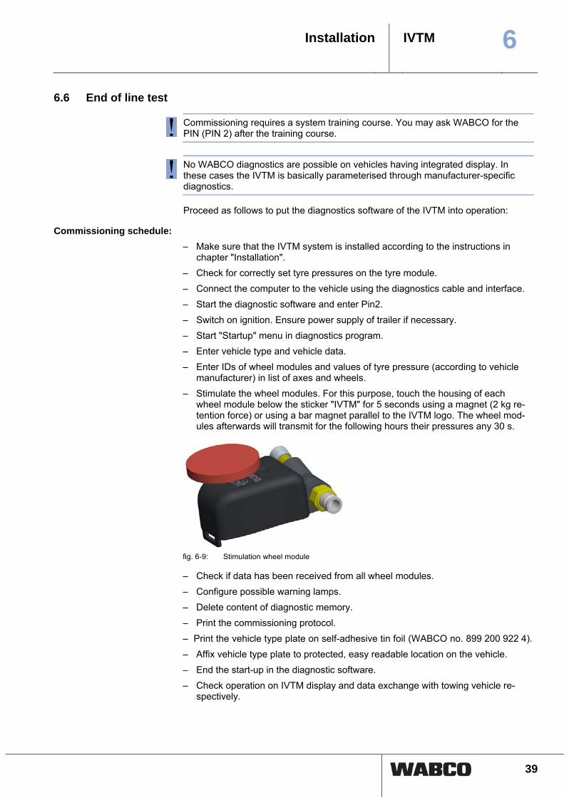
manufacturer) in list of axes and wheels. – Stimulate the wheel modules. For this purpose, touch the housing of each
wheel module below the sticker "IVTM" for 5 seconds using a magnet (2 kg re-tention force) or using a bar magnet parallel to the IVTM logo. The wheel mod-ules afterwards will transmit for the following hours their pressures any 30 s.
fig. 6-9: Stimulation wheel module
– Check if data has been received from all wheel modules. – Configure possible warning lamps. – Delete content of diagnostic memory. – Print the commissioning protocol. – Print the vehicle type plate on self-adhesive tin foil (WABCO no. 899 200 922 4). – Affix vehicle type plate to protected, easy readable location on the vehicle. – End the start-up in the diagnostic software. – Check operation on IVTM display and data exchange with towing vehicle re-
spectively.

7 IVTM
Workshop instructions
40
7 Workshop instructions
This chapter provides information for the repair. Furthermore, you will also receive help for the case that the product does not function as expected. Please observe the instructions for disposal at the end of the chapter.
WARNING
– Definitely respect valid health and safety regulations of the country concerned and workshop as well as vehicle manufacturer instructions.
WARNING
Rolling away of the vehicle – Vehicles not secured may roll away during the assembly. This might lead to
severe injuries or even death. Secure the vehicle against rolling away before carrying out work on the vehicle.
WARNING
Danger to health due to dust – Dusts that are dangerous to health are generated when the rim is cleaned us-
ing compressed air. For this purpose, do not clean the rims using compressed air.
WARNING
Loose wheel nuts – Loose wheel nuts may lead to accidents when driving on roads.
Wheel nuts must be tightened with torque specified by vehicle manufacturer. Check the tightness of the wheel nuts after 500 km.
Maintenance IVTM system is maintenance-free. Only when the display indicates a malfunction, fault finding must be performed with diagnosis.
7.1 Diagnostics
Diagnostic components The IVTM diagnostic cable 446 300 348 0 is used for diagnostics on towing vehi-cles. When carrying out diagnostics on trailers, please extract the product number of the required diagnostics components from the chart.
System in trailer vehicles
Type of diagnosis Required components
Vario C VCS ECAS TCE VCS II TEBS before 2004
Diagnostics using diagnostic cable 446 300 329 2
Diagnostic cable 446 300 329 2

IVTM 7Workshop instructions
41
System in trailer vehicles
Type of diagnosis Required components
TEBS since 2004 VCS II
Diagnostics via diagnostic Interface (serial) 446 301 021 0
Diagnostic Interface (serial) 446 301 021 0 CAN converter 446 300 470 0 Connection adapter ISO 7638 with CAN socket 446 300 360 0
TEBS since 2004 VCS II
Diagnostics via diagnostic Interface (USB) 446 301 022 0
Diagnostic Interface (USB) 446 301 022 0 Diagnostic cable 446 300 361 0 Connection adapter ISO 7638 with CAN socket 446 300 360 0
TEBS E Premium (Diagnostic port with yellow cap)
Diagnostics via diagnostic Interface (USB or serial)
Diagnostic Interface (USB or serial) Diagnostic cable 446 300 348 0
Table: 7-1: Diagnostic components for trailer vehicles
Diagnostic Software The diagnostic software is available in various languages. Information concerning the current version of the diagnostic software and language versions available can be obtained in our product database INFORM on the internet (www.wabco-auto.com). The WABCO diagnostic software is self-explanatory. The function of the diagnostic software is described in help texts. The diagnostic memory and current measuring data can be obtained using the di-agnostic software. In the event of malfunctions, the fault will be described and pos-sible countermeasures will be indicated. The ECU settings can not be changed in diagnostic mode. Entering a PIN is re-quired for the parameter settings.
7.2 Wheel Changes
Due to the external fixation of the wheel modules on the wheel bolts after wheel change a new module is not needed. It is only to be ensured, that after wheel ex-change the wheel module is fitted exactly to the same position as before. As long as the wheel module itself is not exchanged, there is no need for new set-tings of system parameters.
The wheel modules are not allowed to be swapped with each other!
Make sure that the wheel modules are respectively located in the same position on the vehicle after the wheel change. Especially with dual tyres, the accurate relationship to the inner or outer wheel must be observed.
Please perform wheel changes as follows: – Remove any dirt from the wheel module and PA tube. – Note ID code of wheel module (engraved on top of the housing) and its position
on the vehicle, e.g. rear axle left, outside. Alternative: Fix a plate with the de-scription of the location to each module.
– Release the union nut of the PA tube on the tyre valve and remove the PA tube from the tyre valve.
– Unscrew firstly only those wheel nuts fixing wheel module(s).

7 IVTM
Workshop instructions
42
– Remove wheel module completely, together with the PA tube. Do not turn the PA tube at the wheel module and do not remove the PA tube from wheel mod-ule unnecessarily. Prevent dirt from entering into the PA tube.
– Check the PA tube for any damage. Replace the PA tube if ageing ruptures or rubbing wear is visible. (see chap-ter 7.3 "Replacing PA tubes", page 42).
– Now remove the residual wheel nuts and change the wheel or the tyre. – Put on the wheel or the wheels again and fix them with some wheel nuts on
wheel bolts not used to fix wheel module or counterweight. – While assembling the wheel make sure that the tyre valve gets its original posi-
tion. With twin tyres, the tyre valves should be placed in opposite position. – Place the wheel module to its original position and fix it with wheel nuts. With
individual wheels, assemble the counterweight to the opposite of the wheel module.
– Screw the union nut of the hose back on to the tyre valve. Tighten union nuts manually only.
– Check that the connection is tight using a leakage indicating spray. – Tighten wheel nuts crosswise as per vehicle manufacturer's instructions.
7.3 Replacing PA tubes
Proceed as follows when replacing a defective PA tube: – Loosen the PA tube from the valve. – Unscrew the V203 connection together with the PA tube from the wheel module.
When removing the PA tube from the wheel module, take care that the thread on
the wheel module is kept clean.
– Check the thread on the wheel module for damage. With damaged thread, re-place the complete wheel module.
– Screw the new V203 connection into the thread of the wheel module. A new V203 connection can be obtained using the WABCO product number 893 770 005 2.
fig. 7-1: VOSS SV 203 connection
– Tighten the V203 connection with a torque of 3 Nm (hand tight). – Remove the protective cap of the V203 connection. – Insert the new, cut to length PA tube (see page 34) into the V203 connection.

IVTM 7Workshop instructions
43
– Check if the PA tube has been pushed in until the stop into the V203 connection. – Check if the PA tube has a tight connection (approx. 20 N). – Connect the PA tube to the valve. – Tighten union nuts on the valve hand tight. – Check that the connection is tight using a leakage indicating spray.
7.4 Replacing hose connections
Replace defective hose connections with PA tubes. At the same time, install a new new wheel module type II. (see chapter 7.5 "Replacing wheel module I with wheel module II", page 43)
7.5 Replacing wheel module I with wheel module II
Always replace wheel module I with wheel module II. Replace the rubber hoses with PA tubes at the same time.
Vehicles with OE equipment
Rubber hoses can be fitted in vehicles installed with OE equipment. Before replac-ing the hoses, observe the release notes of the manufacturer.
The following table facilitates the replacement. Further information for using the wheel module II can be obtained using an applica-tion table on our homepage (www.wabco-auto.com). Open our product database INFORM and open the overview table using the index word "IVTM". In this table, the rims are sorted according to their attachment location, size and manufacturer. Next to an illustration of the respective installation situation, you will also be pro-vided with the product number of the wheel module and connecting tube.
Wheel module I Wheel module II
960 730 001 0 (Independent wheel) 960 731 011 0
960 730 001 0 (twin tyres, Super Single)
960 731 031 0
960 730 006 0 (Independent wheel) 960 731 021 0
960 730 006 0 (twin tyres, Super Single)
960 731 041 0
960 730 013 0 960 731 061 0
960 730 037 0 960 731 019 0
7.6 Creeping pressure loss
When the display hints to a creeping pressure loss, first check the hose connection between valve and wheel module of the relevant wheel with leakage indicating spray. If these connections are tight, check bearing surface and edges. So-called indica-tors at the tyre edges point on damages at the carcass, which usually causes creeping pressure loss of the wheel.

7 IVTM
Workshop instructions
44
If the carcass is damaged, the tyre must be replaced.
7.7 No reception of the wheel module
Battery life Wheel modules get their power supply via an internal lithium battery. In reason of the mechanical demands and tightness, the battery is coated within the wheel module and cannot be exchanged. The battery life-time depends on certain factors. Under usual circumstances the life-time will be longer than 5 years. Since significant pressure deviation increases transmission frequency for short-term warning, often pressure changes cause a shorter life time.
Check list If the warning "no reception wheel module" is repeated often in the display (see figure 5-7, page 31), using the check list, you are able to determine if the wheel module should be replaced. Copy in this table line per line the default value to the result column if the description matches. Then compare the sum of all results with the details below.
Ensure while trouble shooting that the vehicle is not in vicinity of high-frequency
radiation (see chapter 4.1, page 18).

IVTM 7Workshop instructions
45
No. Description Default Result 1a Warning "no reception" is not active but
stored in diagnostic memory (failure shown blue in diagnosis)
0
1b Warning "no reception" is active (failure shown in red in diagnosis)
2
2a Warning "no reception" is given for one wheel module
0
2b Warning "no reception" is given for several wheel modules
3
3a The age of the wheel module (according to the engraved production date in format wwyy) is less than 5 years
0
3b The age of the wheel module lies between 5 and 7 years
4
3c The age of the wheel module is more than 7 years
8
4a The average outside temperature was -20 °C while occurrence of the failure
0
4b The average outside temperature was 0 °C while occurrence of the failure
3
4c The average outside temperature was +20 °C while occurrence of the failure
5
5a The activation of the wheel module with bar magnet (see figure 6-9, page 39) was not successful.
0
5b The activation of the wheel module with bar magnet was not successful.
4
Sum
Table: 7-2: Check list wheel module
Test result: Sum between 0 and 11: • The battery of the wheel module is in order. The loss of the wheel module from
time to time might be caused by deep temperature, contamination of wheel module / ECU or a not optimised installation position of the ECU.
Sum between 12 and 15: • It is recommended to observe transmission of the relevant wheel module further
on and to replace it if necessary.
Sum between 16 and 22: • Battery of wheel module exhausted. Replace wheel module with a new one.
Parameterise ID of the new module to the ECU via diagnosis.

7 IVTM
Workshop instructions
46
7.8 Disposal
The components of the system are electronic waste and should therefore not be disposed of with domestic waste. Ob-serve all laws and guidelines of your country when disposing. This applies in particular to the wheel modules that contain lithium batteries. These have been coated within the housing and cannot be exchanged. After reaching its life cycle, dispose of the wheel module when observing all laws and guidelines of your country. WABCO makes efforts to protect the environment. All compo-nents can be returned to WABCO as with other used devices. Please contact your WABCO sales partner for details.


© 2
008
WA
BCO
All
right
s re
serv
ed 8
15 0
10 0
45 3
/05.
2008
WABCO Vehicle Control Systems is one of the world's leading providers of elec-tronic braking, stability, suspension and transmission automation systems for heavy duty commercial vehicles. Cus-tomers include the world’s leading commercial truck, trailer, and bus manu-facturers. Founded in the U.S. in 1869 as Westinghouse Air Brake Company, WABCO was acquired by American
Standard in 1968 and spun off in 2007. Headquartered in Brussels, Belgium, WABCO employs more than 7,700 peo-ple in 31 countries worldwide. In 2007, WABCO’s total sales were $2.4 billion. WABCO is a publicly traded company and is listed on the New York Stock Exchange with the stock symbol WBC www.wabco-auto.com