TyrePal Tyre Pressure Monitoring System with compact ...
14
Wheel Solutions Limited, Unit 2 Upper Keys Business Park, Keys Park Road, Hednesford, Cannock, Staffordshire, WS12 2GE, United Kingdom Tel: +44 (0)1543 870 170 e-mail: [email protected] www.tyrepal.co.uk TC215B 20141211 © TyrePal Ltd 2013 Page 1 TyrePal Tyre Pressure Monitoring System with compact sensors TC215B User Manual Innovative safety solutions for your peace of mind
Transcript of TyrePal Tyre Pressure Monitoring System with compact ...

Wheel Solutions Limited, Unit 2 Upper Keys Business Park, Keys Park Road, Hednesford,
Cannock, Staffordshire, WS12 2GE, United Kingdom
Tel: +44 (0)1543 870 170 e-mail: [email protected] www.tyrepal.co.uk
TC215B 20141211 © TyrePal Ltd 2013 Page 1
TyrePal Tyre Pressure Monitoring System
with compact sensors
TC215B
User Manual
Innovative safety solutions for your peace of mind
Wheel Solutions Limited, Unit 2 Upper Keys Business Park, Keys Park Road, Hednesford,
Cannock, Staffordshire, WS12 2GE, United Kingdom
Tel: +44 (0)1543 870 170 e-mail: [email protected] www.tyrepal.co.uk
TC215B 20141103 © TyrePal Ltd 2013 Page 2
CONTENTS
1. SYSTEM COMPONENTS ..................................................... 3
1.1 Monitor and accessories .............................................. 3
1.2 Sensors ..................................................................... 3
1.3 Optional components .................................................. 3
1.4 Monitor layout and controls ......................................... 4
1.5 Screen icons .............................................................. 4
2. IMPORTANT SAFETY NOTES .............................................. 4
3. BEFORE INSTALLATION ..................................................... 5
3.1 Wheel balancing ......................................................... 5
3.2 Battery charging ......................................................... 5
3.3 Sensors and wheel positions ....................................... 5
4. INSTALLATION.................................................................. 6
4.1 Install and register the sensors ................................... 6
4.2 Deleting a sensor setting ............................................. 6
4.3 Lock the sensors ......................................................... 6
4.4 Test for leaks ............................................................. 6
4.5 Set units and alert levels ............................................. 7
4.6 Install the monitor ...................................................... 8
4.7 Connect the power ..................................................... 9
5. OPERATION ...................................................................... 9
5.1 Sleep mode ................................................................ 9
5.2 Alerts ......................................................................... 9
5.3 Backlight .................................................................. 11
5.4 Connecting and disconnecting a trailer....................... 11
5.5 Replacing sensor batteries ........................................ 11
6. TESTING THE SETUP ....................................................... 12
7. SIGNAL REPEATER (OPTIONAL EQUIPMENT) .................... 12
8. TROUBLESHOOTING AND ADDITIONAL INFORMATION ..... 12
9. SPARES, SERVICE AND WARRANTY .................................. 13
10. SPECIFICATION SUMMARY ............................................ 13

Wheel Solutions Limited, Unit 2 Upper Keys Business Park, Keys Park Road, Hednesford,
Cannock, Staffordshire, WS12 2GE, United Kingdom
Tel: +44 (0)1543 870 170 e-mail: [email protected] www.tyrepal.co.uk
TC215B 20141211 © TyrePal Ltd 2013 Page 3
1. SYSTEM COMPONENTS
1.1 Monitor and accessories
1.2 Sensors
The system can be supplied with TCSB compact sensors that can be used for tyre
pressures up to 99psi / 6.8 bar. The monitor is also compatible with TCSE sensors for
higher pressures (up to 188psi / 13 bar) and also TPMS INT 01 internal sensors fitted to
TyrePal TPMS Ready systems. If different sensors are used, the operation of the monitor
may not be exactly as described in this manual.
The sensors have integral locking screws which can be used to prevent casual theft.
The box may also contain some spare O-rings that can be used as replacement seals when
the sensor batteries are replaced.
1.3 Optional components
The system may be supplied with optional parts such as a Signal Repeater. This is used to
extend the range of the sensor signals and can also store trailer settings to simplify
exchanging trailers in a fleet.
Wheel Solutions Limited, Unit 2 Upper Keys Business Park, Keys Park Road, Hednesford,
Cannock, Staffordshire, WS12 2GE, United Kingdom
Tel: +44 (0)1543 870 170 e-mail: [email protected] www.tyrepal.co.uk
TC215B 20141103 © TyrePal Ltd 2013 Page 4
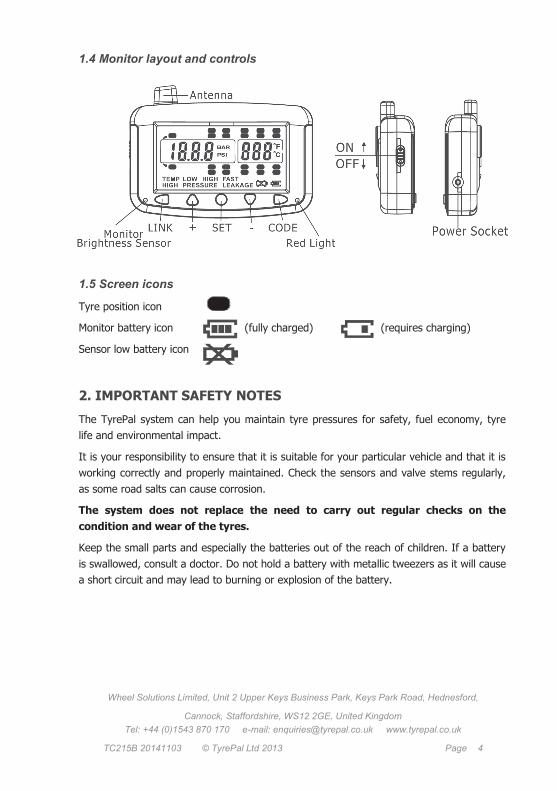
1.4 Monitor layout and controls
1.5 Screen icons
Tyre position icon
Monitor battery icon (fully charged) (requires charging)
Sensor low battery icon
2. IMPORTANT SAFETY NOTES
The TyrePal system can help you maintain tyre pressures for safety, fuel economy, tyre
life and environmental impact.
It is your responsibility to ensure that it is suitable for your particular vehicle and that it is
working correctly and properly maintained. Check the sensors and valve stems regularly,
as some road salts can cause corrosion.
The system does not replace the need to carry out regular checks on the
condition and wear of the tyres.
Keep the small parts and especially the batteries out of the reach of children. If a battery
is swallowed, consult a doctor. Do not hold a battery with metallic tweezers as it will cause
a short circuit and may lead to burning or explosion of the battery.

Wheel Solutions Limited, Unit 2 Upper Keys Business Park, Keys Park Road, Hednesford,
Cannock, Staffordshire, WS12 2GE, United Kingdom
Tel: +44 (0)1543 870 170 e-mail: [email protected] www.tyrepal.co.uk
TC215B 20141211 © TyrePal Ltd 2013 Page 5
3. BEFORE INSTALLATION
Before installing the system, ensure that it is suitable for your vehicle.
Check that the operating pressure of your tyres is within the range of the system.
i.e. 0-99psi (0-6.8 bar)
Check that tyre valve stems are in good condition before fitting the sensors. We
do not recommend using the system with aluminium valve stems. (Because of the
possibility of corrosion between dissimilar metals).
Do not fit sensors to tyres that have been treated with internal tyre sealant. The
sealant may damage the sensor or impair its action.
To avoid danger of damage to the sensors, check that sensor valve caps will
remain within the outside profile of the tyres when fitted.
If the distance from the rear wheels to the monitor is greater than about 7 metres, we
recommend the use of a TyrePal Signal Repeater to increase the range of the sensors and
improve the stability of the system
3.1 Wheel balancing
The weight of the sensors is within the tolerance achieved for wheel balancing, so there is
usually no need for the wheels to be rebalanced after installing the system. If vibration is
felt when driving at speed after fitting the system, the wheels must be rebalanced.
3.2 Battery charging
The monitor is powered from an internal rechargeable battery that may need to be
charged before first use. A full charge will last for about 60 hours operation. It can be
charged from the vehicle 12-24V supply using the supplied cigarette lighter lead.
3.3 Sensors and wheel positions
Sensors are interchangeable and can be registered to any of the 22 possible wheel
positions. Once sensors are registered, the display only shows data from the registered
positions. We recommend that you label each sensor, with the supplied labels to identify
its position and record the positions below as to which tyre positions you wish to monitor:
Wheel Solutions Limited, Unit 2 Upper Keys Business Park, Keys Park Road, Hednesford,
Cannock, Staffordshire, WS12 2GE, United Kingdom
Tel: +44 (0)1543 870 170 e-mail: [email protected] www.tyrepal.co.uk
TC215B 20141103 © TyrePal Ltd 2013 Page 6
4. INSTALLATION
4.1 Install and register the sensors
The following procedure registers the sensors as they are installed.
1. In standby mode, press and hold the CODE button for 3 seconds. Release it after
the beep to enter coding mode. A flashing tyre icon is displayed. If no sensor is
registered to this position, the letters FFF FFF are shown. If a sensor is already
registered, the sensor ID is shown.
2. To select the desired tyre position to be monitored, press the + or – button to
scroll through to the desired position.
3. Screw the sensor onto the tyre valve. As it senses the air pressure, the sensor
sends its ID code to the monitor. The monitor beeps and stores the tyre position
with that sensor ID. If it does not register within a few seconds, unscrew the
sensor and try again.
4. Press + or – buttons to select the other tyres and repeat for all the tyres that are
to be monitored.
5. When all sensors are registered, press and hold the CODE button to exit.
4.2 Deleting a sensor setting
If you need to delete a setting, whilst in standby mode press and hold the CODE button
for 3 seconds, release it after the beep to enter the coding mode. A flashing tyre icon and
ID code are displayed. Use the + or - buttons to select the tyre position then press and
hold the SET button for 3 seconds. A double beep confirms the ID has been deleted.
Note: If a sensor is coded twice to the same monitor, the
previous setting will be deleted automatically.
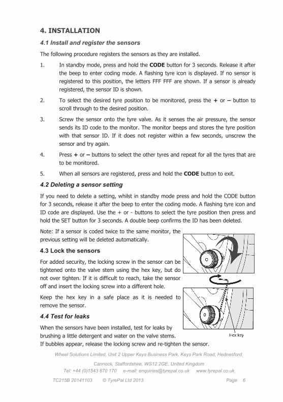
4.3 Lock the sensors
For added security, the locking screw in the sensor can be
tightened onto the valve stem using the hex key, but do
not over tighten. If it is difficult to reach, take the sensor
off and insert the locking screw into a different hole.
Keep the hex key in a safe place as it is needed to
remove the sensor.
4.4 Test for leaks
When the sensors have been installed, test for leaks by
brushing a little detergent and water on the valve stems.
If bubbles appear, release the locking screw and re-tighten the sensor.

Wheel Solutions Limited, Unit 2 Upper Keys Business Park, Keys Park Road, Hednesford,
Cannock, Staffordshire, WS12 2GE, United Kingdom
Tel: +44 (0)1543 870 170 e-mail: [email protected] www.tyrepal.co.uk
TC215B 20141211 © TyrePal Ltd 2013 Page 7
4.5 Set units of pressure and alert levels
Pressure units can be set to display in psi or bar, and temperature in °C or ˚F. Pressure
alerts are set individually for each of the three axles on the towing vehicle (tractor) while
the trailer settings apply to all axles on the trailer. We recommend that the high pressure
alert is set at 20% above the manufacturer’s recommended pressure, and the low alert
15% below. The temperature alert level applies to all tyres. The factory set default is 70°C
and we recommend that this is not changed.
1. In standby mode, press and hold the SET button for 3 seconds. Release after the
beep. Press the SET button repeatedly to scroll through the different settings and
press the + or – buttons to adjust the setting as follows:
2. Pressure units: while the PSI or BAR icon is
flashing, press the + or – button to select the
desired units. Then press SET to move on to
set temperature units.
3. Temperature units: while the °C or ˚F is
flashing, press the + or – buttons to select
and press SET again to move on to set the
high pressure alert level for the first axle.
4. First axle pressure alert levels: Press + or –
to adjust the high pressure setting, then
press SET to move on to set the low pressure
alert for this axle.
Note that the system will not allow the high pressure alert to be less than the low pressure
alert level. The factory set low pressure level is set to 30psi, so if you want the high
pressure alert level below 30psi, you must set the low pressure alert levels first, then cycle
though again to set the high pressure alerts.
5. Continue to cycle through high and low pressure settings for the three axles on
the tractor unit and all three axles on the trailer.
6. High temperature alert for all wheels: Press + or – to adjust the setting as
required. The factory setting of 70°C is a minimum and is suitable for most
applications.
7. Press and hold the SET button for three seconds to save the settings and exit the
settings mode. If no action is taken for 1 minute, the system will return to standby
mode without making any changes.
The alert levels can be adjusted at any time using this procedure, for example if different
pressures are required when not towing a trailer. The new settings take immediate effect.

Wheel Solutions Limited, Unit 2 Upper Keys Business Park, Keys Park Road, Hednesford,
Cannock, Staffordshire, WS12 2GE, United Kingdom
Tel: +44 (0)1543 870 170 e-mail: [email protected] www.tyrepal.co.uk
TC215B 20141103 © TyrePal Ltd 2013 Page 8
4.6 Install the monitor
Various fixing options are available for the monitor. Make sure it does not obstruct the
driver’s view when installed.
Click the monitor into position. If required the monitor can be removed by unclipping it
from the mount.
4.7 Connect the power
Connect the monitor to the vehicle power supply (12V or 24V) via the power adapter to
charge the battery. A full charge will last for about 60 hours of operation.
Windscreen mount:
Clip the monitor to the holder, moisten the suction pad and
press it to the windscreen. Lower the lever to secure the
pad to the windscreen.
To remove it, lift the lever to break the suction, or unclip
the monitor from the holder.
Free standing:
Fit the monitor stand in the holes in the back of the
monitor and position it where it can be seen. Note that the
stand is a tight fit in the holes.
Screw mount:
The monitor mount can be permanently fixed to the
vehicle with the bracket. To use the screw mounting
option, dismantle the suction holder and re-assemble it
Wheel Solutions Limited, Unit 2 Upper Keys Business Park, Keys Park Road, Hednesford,
Cannock, Staffordshire, WS12 2GE, United Kingdom
Tel: +44 (0)1543 870 170 e-mail: [email protected] www.tyrepal.co.uk
TC215B 20141211 © TyrePal Ltd 2013 Page 9
5. Operation
In normal operation the monitor continuously scrolls through and displays the pressure
and temperature of the tyres one by one. You can manually scroll through to any
particular tyre by using the + or - buttons. The system is accurate to +/- 1.5psi (0.1bar ),
so a difference of one or two psi between the tyres can safely be ignored.
The sensors check the pressure and temperature every few seconds while the vehicle is
moving. If the pressure is falling, data is transmitted to the monitor immediately, but if the
pressure is steady, data is transmitted only every five minutes. This is to reduce power
consumption and extend the life of the sensor batteries.
5.1 Sleep mode
The monitor has a built-in motion sensor that shuts it down into a sleep mode after about
ten minutes of no movement so it does not normally need to be turned off. Any vibration
such as opening the vehicle door wakes it up again. If the vehicle is to be unused for
some time, we recommend turning the monitor off to prevent battery drain.
The sensors supplied with this model also have a sleep mode, and when the vehicle has
been stationary for several minutes, they stop transmitting to save battery power. When
the monitor wakes (after a door is opened for example), the display will scroll though the
monitored tyres, but no pressures or temperatures will be shown. It will also chirp at each
monitored position. However, once you begin to drive, within a few hundred metres, the
sensors will wake and the monitor will display the pressures and temperatures and the
chirping will cease.
5.2 Alerts
If a sensor battery is low, or if a signal is not received from a sensor for a period of 60
minutes, an alert is issued.
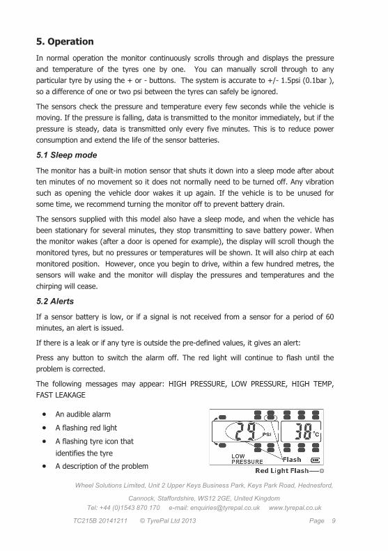
If there is a leak or if any tyre is outside the pre-defined values, it gives an alert:
Press any button to switch the alarm off. The red light will continue to flash until the
problem is corrected.
The following messages may appear: HIGH PRESSURE, LOW PRESSURE, HIGH TEMP,
FAST LEAKAGE
An audible alarm
A flashing red light
A flashing tyre icon that
identifies the tyre
A description of the problem

Wheel Solutions Limited, Unit 2 Upper Keys Business Park, Keys Park Road, Hednesford,
Cannock, Staffordshire, WS12 2GE, United Kingdom
Tel: +44 (0)1543 870 170 e-mail: [email protected] www.tyrepal.co.uk
TC215B 20141103 © TyrePal Ltd 2013 Page 10
The FAST LEAKAGE alert is a serious situation that could rapidly affect the stability of
the vehicle. If this alert appears it means that there has been a loss of 0.14bar/2psi within
1 minute , so you should pull over and investigate immediately.
Sensor battery alert:
When a sensor battery needs replacing, a low sensor battery icon is shown, and the
appropriate tyre icon flashes.
Monitor battery alert:
When fully charged, the monitor battery will operate for 60 hours. When it needs
charging, the monitor battery icon changes from full to part full. Connect the monitor to
the vehicle power supply and the icon becomes animated while charging. It is not harmed
by partial charging and does not have to be fully discharged before recharging.
The HIGH TEMPERATURE alert shows
that the tyre is overheating.
If not corrected, this can cause
permanent damage to the sidewall
of the tyre and will potentially lead
to a blowout or a fire.
Fully
charged
Requires
charging
Wheel Solutions Limited, Unit 2 Upper Keys Business Park, Keys Park Road, Hednesford,
Cannock, Staffordshire, WS12 2GE, United Kingdom
Tel: +44 (0)1543 870 170 e-mail: [email protected] www.tyrepal.co.uk
TC215B 20141211 © TyrePal Ltd 2013 Page 11
5.3 Backlight
The backlight turns on automatically when it gets dark if the vehicle is in motion. It turns
off when it is light or when the monitor is in sleep mode. Press any button to turn the
backlight on manually. To turn it off, press and hold the + button for 3 seconds.
5.4 Connecting and disconnecting a trailer
When the trailer is not connected to the vehicle, press the LINK and – buttons at the
same time. Trailer monitoring stops and the trailer tyre icons are removed from the
display. When the trailer is reconnected, press LINK and + buttons to display the trailer.
If you drive away from the trailer without unlinking the monitor, it may continue to show
the last measured trailer tyre data for a period of time. After about 60 minutes it will stop
displaying data for the trailer tyres and will give a short beep each time the trailer tyre
position is accessed.
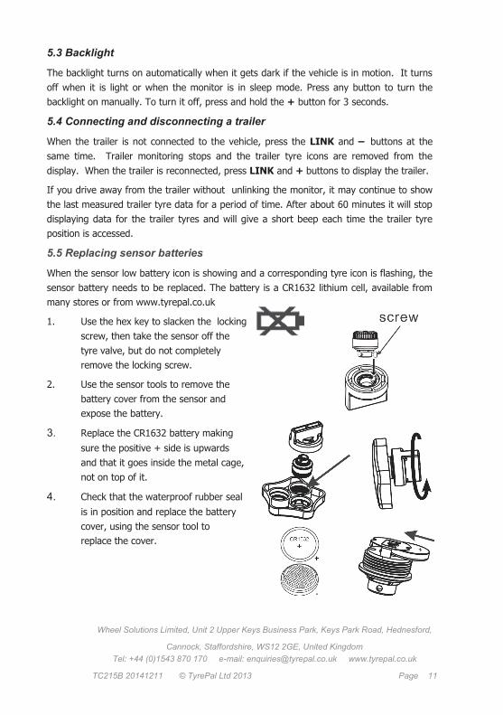
5.5 Replacing sensor batteries
When the sensor low battery icon is showing and a corresponding tyre icon is flashing, the
sensor battery needs to be replaced. The battery is a CR1632 lithium cell, available from
many stores or from www.tyrepal.co.uk
1. Use the hex key to slacken the locking
screw, then take the sensor off the
tyre valve, but do not completely
remove the locking screw.
2. Use the sensor tools to remove the
battery cover from the sensor and
expose the battery.
3. Replace the CR1632 battery making
sure the positive + side is upwards
and that it goes inside the metal cage,
not on top of it.
4. Check that the waterproof rubber seal
is in position and replace the battery
cover, using the sensor tool to
replace the cover.
Wheel Solutions Limited, Unit 2 Upper Keys Business Park, Keys Park Road, Hednesford,
Cannock, Staffordshire, WS12 2GE, United Kingdom
Tel: +44 (0)1543 870 170 e-mail: [email protected] www.tyrepal.co.uk
TC215B 20141103 © TyrePal Ltd 2013 Page 12
6. TESTING THE SETUP
To test the transmission range on first installation, position the monitor in the driver’s cab
and unscrew the furthest sensor. The system should produce an alert for that tyre posi-
tion, within about 10 seconds. Tighten the sensor and the alert should stop.
This test must be carried out within a few minutes of the installation or after the vehicle
has been in motion, as the sensor will not transmit if it is in the sleep mode. Simply
moving the sensor about or unscrewing it will not reactivate it from the sleep mode.
If the alert is not given, the sensor may be out of range. The sensors have a transmission
range of about 20 metres in open air, but in practice, screening by the vehicle chassis and
bodywork reduce the working distance to about 7 metres. This can be increased by using
the optional Signal Repeater.
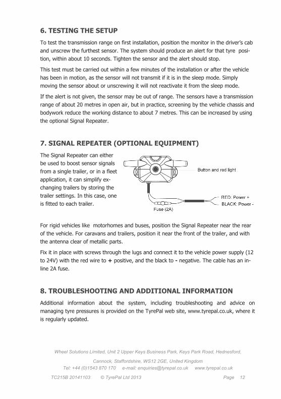
7. SIGNAL REPEATER (OPTIONAL EQUIPMENT)
The Signal Repeater can either
be used to boost sensor signals
from a single trailer, or in a fleet
application, it can simplify ex-
changing trailers by storing the
trailer settings. In this case, one
is fitted to each trailer.
For rigid vehicles like motorhomes and buses, position the Signal Repeater near the rear
of the vehicle. For caravans and trailers, position it near the front of the trailer, and with
the antenna clear of metallic parts.
Fix it in place with screws through the lugs and connect it to the vehicle power supply (12
to 24V) with the red wire to + positive, and the black to - negative. The cable has an in-
line 2A fuse.
8. TROUBLESHOOTING AND ADDITIONAL INFORMATION
Additional information about the system, including troubleshooting and advice on
managing tyre pressures is provided on the TyrePal web site, www.tyrepal.co.uk, where it
is regularly updated.

Wheel Solutions Limited, Unit 2 Upper Keys Business Park, Keys Park Road, Hednesford,
Cannock, Staffordshire, WS12 2GE, United Kingdom
Tel: +44 (0)1543 870 170 e-mail: [email protected] www.tyrepal.co.uk
TC215B 20141211 © TyrePal Ltd 2013 Page 13
9. SPARES, SERVICE AND WARRANTY
Spare parts including batteries and replacement sensors are available to purchase from
the TyrePal web site.
Please register your guarantee by completing details on our web site.
The system is warranted to be free from manufacturing defects and is guaranteed for a
period of twelve months from date of purchase. There are no user-serviceable parts inside
the monitor and if internal parts have been tampered with, the warranty may be void. The
warranty does not affect your statutory rights.
10. SPECIFICATION SUMMARY
Specification is subject to change without notice.
Monitor
Dimensions 115 x 73 x 27mm, weight 132g.
Power Powered by internal lithium battery recharged from vehicle power supply. Automatically shuts down when not in use and reactivates as vehicle is used. Charger input 12 to 24V dc. Battery life is approximately 60 hours per charge.
Display Clear LCD screen with automatic backlight. View size 80 x 40mm. Continuously cycles through all wheel positions and displays pressure and temperature for each tyre. Additional detail is displayed as required.
Alerts Bright red flashing LED, plus audible alarm. Audible alarm can be silenced by pressing any button. Distinct alerts are given for the following conditions:
Fast leakage (puncture etc) Pressure below user-set threshold Pressure above user-set threshold Temperature above user-set threshold (potential blowout)
Warnings are also given if the sensor signal is lost, if a sensor battery is low or when the monitor battery needs recharging.
Units User selected. Pressure: PSI or bar, Temperature: °C or °F

Wheel Solutions Limited, Unit 2 Upper Keys Business Park, Keys Park Road, Hednesford,
Cannock, Staffordshire, WS12 2GE, United Kingdom
Tel: +44 (0)1543 870 170 e-mail: [email protected] www.tyrepal.co.uk
TC215B 20141103 © TyrePal Ltd 2013 Page 14
Sensors
Dimensions Dimensions: 20.5 x 20.5mm (length x diameter). When fitted, they
extend approx. 12mm beyond the length of the tyre valve. Weight 12g.
Power Replaceable CR1632 cell, expected life up to 2 years
Pressure 0 to 99psi +/-1.5psi (0 to 6.8 bar +/- 0.1bar)
Temperature -40˚C to 80˚C ±3˚C
Transmission 433.92MHz, power <10dBm
Range Typically circa 7m in vehicle when screened by bodywork etc. Range can
be extended with a Signal Repeater.