Item 1: The pile cap weight and the pile weight should be ...
24
Koury Engineering and Testing, Inc. · (909) 606-6111 · www.kouryengineering.com Chino · Gardena · San Diego January 3, 2020 Project No. 17-0822 Ms. Allison Coburn, Facilities Project Manager Facility Planning, District Construction and Support Services 2323 North Broadway, Suite 112 Santa Ana, California, 92706-1640 SUBJECT: Addendum Response to DSA Comments for Santa Ana College New Health Science Building 1530 W. 17 th Street, Santa Ana, CA 92706 Reference: Response to DSA Comments for Santa Ana College New Health Science Building, 1530 W. 17 th Street, Santa Ana, CA 92706, prepared by Koury Engineering & Testing, Inc., report dated November 14, 2019. Dear Ms. Coburn: This addendum report is in response to verbal discussions between the Division of State Architect (DSA) reviewer, CGS and the Design Team during a telephone conference on December 10, 2019. Item 1: The pile cap weight and the pile weight should be subtracted from the pile capacity. Response to Item 1: It was agreed that the pile weight will be subtracted from the pile side resistance capacity (end bearing is neglected). The pile cap weight will be added to the column loads by the Structural Engineer. It is acceptable to consider the pile cap net weight (concrete weight minus displaced soil weight) for compression, and the pile cap full weight for tension. Since the safety factor against uplift generally exceed 3, there is no need to consider the side friction at the perimeter of the pile cap. Item 2: The DSA reviewer indicated the need for a safety factor of 2 during a liquefaction event. The California Building Code apparently does not distinguish between a liquefaction event or any other type of event for foundation support. Response to Item 2: Based on SP117A (page 42, attached), a calculated safety factor greater than 1.5 can be used against potential foundation bearing failure or large foundation settlement during a liquefaction event. The previous pile calculations provided indicate safety factors greater than 1.5. However, Koury agreed to review the design parameters and to adjust the pile length as needed to obtain safety factors of at least 2 as requested by DSA.
Transcript of Item 1: The pile cap weight and the pile weight should be ...
Koury Engineering and Testing, Inc. · (909) 606-6111 · www.kouryengineering.com Chino · Gardena · San Diego
January 3, 2020 Project No. 17-0822 Ms. Allison Coburn, Facilities Project Manager Facility Planning, District Construction and Support Services 2323 North Broadway, Suite 112 Santa Ana, California, 92706-1640 SUBJECT: Addendum Response to DSA Comments for
Santa Ana College New Health Science Building 1530 W. 17th Street, Santa Ana, CA 92706 Reference: Response to DSA Comments for Santa Ana College New Health Science
Building, 1530 W. 17th Street, Santa Ana, CA 92706, prepared by Koury Engineering & Testing, Inc., report dated November 14, 2019.
Dear Ms. Coburn: This addendum report is in response to verbal discussions between the Division of State Architect (DSA) reviewer, CGS and the Design Team during a telephone conference on December 10, 2019. Item 1: The pile cap weight and the pile weight should be subtracted from the pile capacity. Response to Item 1: It was agreed that the pile weight will be subtracted from the pile side resistance capacity (end bearing is neglected). The pile cap weight will be added to the column loads by the Structural Engineer. It is acceptable to consider the pile cap net weight (concrete weight minus displaced soil weight) for compression, and the pile cap full weight for tension. Since the safety factor against uplift generally exceed 3, there is no need to consider the side friction at the perimeter of the pile cap. Item 2: The DSA reviewer indicated the need for a safety factor of 2 during a liquefaction event. The California Building Code apparently does not distinguish between a liquefaction event or any other type of event for foundation support. Response to Item 2: Based on SP117A (page 42, attached), a calculated safety factor greater than 1.5 can be used against potential foundation bearing failure or large foundation settlement during a liquefaction event. The previous pile calculations provided indicate safety factors greater than 1.5. However, Koury agreed to review the design parameters and to adjust the pile length as needed to obtain safety factors of at least 2 as requested by DSA.


ATTACHMENT 1
Table 2A


30-in Pile Depth
(ft)
Side Friction Ignored from - to
Depth (ft)
Ultimate Capacity Down (kips)
Ultimate Capacity Up
(kips)
Side Resistance Down (kips)
Side Resistance Up
(kips)
Safety Factor Down
Safety Factor Up
Allowable Static Capacity
Compression (kips)
Allowable Static Capacity Uplift
(kips)
Pile Weight(kips)
540 - 6.5 36 - 3848 - 50
286 338 320 303 2.2 4.7 130 65 34
590-7, 36-38
48-50, 54.5-57304 357 340 320 2.0 4.3 150 75 37
650-8, 36-38
48-50, 54.5-57352 406 391 367 2.1 4.5 165 82 39
690-8.5, 36-38
48-50, 54.5-5766 - 68.5
362 411 403 369 2.0 4.1 180 90 41
30-in Pile Depth
(ft)
Side Friction Ignored from - to
Depth (ft)
Ultimate Capacity Down (kips)
Ultimate Capacity Up
(kips)
Side Resistance Down (kips)
Side Resistance Up
(kips)
Safety Factor Down
Safety Factor Up
Allowable Static Capacity
Compression (kips)
Allowable Static Capacity Uplift
(kips)
Pile Weight(kips)
540 - 6.5 36 - 3848 - 50
286 335 321 301 2.2 4.6 130 65 34
590-7, 36-38
48-50, 54.5-57304 335 341 316 2.0 4.2 150 75 37
650-6, 36-38
48-50, 54.5-57 358 406 397 367 2.2 4.5 165 82 39
650-4.5, 36-38
48-50, 54.5-57 363 412 402 372 2.1 4.4 170 85 39
690-8.5, 36-38
48-50, 54.5-5766 - 68.5
362 411 403 371 2.0 4.1 180 90 41
Zero end bearing was used for all pilesUltimate Capacity Up = Side Resistance Up + Pile Weight
Project #: 17-0822
Example: Down: (320.7‐34.4)/(130*1.33)*1.33=2.2; where Pile Weight=34.4 kips Example Up: (303.5)/(65*1.33)*1.33=4.7
Based on Soil Profile CPT‐2 (Worst Case) Capacity from ALLPILE Analysis
Notes:
Ultimate Capacity Down = Side Resistance Down ‐ Pile Weight
Table 2A- Breakdown of Piles Capacity & Ultimate Resistance During Earthquake (Jan 2, 2020)
Based on Soil Profile Boring B‐2 (Worst Case) Capacity from ALLPILE Analysis
ATTACHMENT 2
ALLPILE Output

Pile-B-2-30in-49ft+5ft Dec 2019-Seismic***************************************************************** ALLPILE 7 VERTICAL ANALYSIS SUMMARY OUTPUT Copyright by CivilTech Software www.civiltech.com *****************************************************************Licensed to Date: 12/27/2019 File: G:\Projects\2017\17-0822 Russell Hall Replacement Project Soils Investigation\Soils Folder\Soils Reports-Certificates\Mehrab Draft\Response to CGS-Pile\Per Jacques\B-2\December Analysis\Pile-B-2-30in-49ft+5ft Dec 2019-Seismic.alp
Title 1: 17-0822-Russel Hall ReplacementTitle 2: Deep Foundation Calculation
ALLPILE INPUT DATA:__________________________________________________________
* Pile Type Page *Unit: EnglishDiameter more than 24in (61cm). For bell section, select "Belled" in Diameter Variation (Pile Section Screen, Item 4). Recommendation: 2 to 4in Item 3 of Page F.Pile Type: Drilled Shaft (dia >24 in. or 61 cm)
* Pile Profile *Foundation Depth: 54.0 -ftTop Height: 0.0 -ftSlope Angle: 0Pile Angle: 0.0
* Pile Properties * Zs Width Area Perim. I E Weight Mix* Out In Other Type -ft -in -in2 -in -in4 -kp/i2 -kp/f % Side Side Par.
______________________________________________________________________________________________________ 0.0 30 706.9 94.2 0 3000 0.736 0.0 3 3 30 Concrete (rough)
54.0 30 706.9 94.2 Pile TipNote: Mix = % of Inside material/Outside material
Group Type: 0Top Type: 1
Water Table: 36.5 -ftNo Elevation Input
* Soil Properties * Zs Gamma Phi C K E50/Dr Nspt Type Soil -ft -lb/f3 o -kp/f2 -lb/i3 - % 0.0 126.6 15 0.33 222.9 1.00 8 1 Soft Clay 5.0 128.7 30 0.2 290.1 0.90 10 3 Silt (Phi + C)
10.0 125.5 20 0.46 166.5 1.11 7 1 Soft Clay 16.0 132.0 32 0.26 584.7 0.67 16 3 Silt (Phi + C) 17.5 130.8 20 0.53 407.0 0.78 12 1 Soft Clay 36.5 66.9 32 0.26 317.7 0.87 10 3 Silt (Phi + C) 40.0 63.8 20 0.53 214.1 1.01 8 1 Soft Clay 45.5 75.6 31 0.15 97.1 66.4 31 4 Sand/Gravel 48.0 75.6 1 0.01 97.1 66.40 31 4 Sand/Gravel 50.0 75.6 31 0.15 97.1 66.4 31 4 Sand/Gravel
Surcharge Pressure on ground: 0 -kp/f2
* Zero Tip Resistance *The tip resistance is zero
* Zero Friction * Zero Friction Start: 0 -ft End: 6.5 -ft
Zero Friction Start: 36 -ft End: 38 -ft
ALLPILE ANALYSIS AND RESULTS:__________________________________________________________
TOTAL LOADS: Vertical Load, Q: 173.0 -kp
Page 1

Pile-B-2-30in-49ft+5ft Dec 2019-Seismic Vertical Load with Load Factor, Q: 173.0 -kp Vertical Load with Load factor and Pile Cap, Q= 173.0 -kp Load Factor for Vertical Load and Torsion= 1.0 Vertical Loads Supported by Pile Cap: 0 % Load Factor for Vertical Loads: 1.0
PILE PROFILE: Pile Length, L= 54.0 -ft Top Height, H= 0.0 -ft Slope Angle, As= 0 Batter Angle, Ab= 0.00 Batter Factor, Kbat= 1.00 *To consider the influence of different soils below the pile tip, bearing stratum is defined from pile tip extending to 4 Diameter of pile, which is 10.0-ft (Input Page F, Item 3)
SINGLE PILE: Kdown= 0.5 Kup= 0.4 Ka= 1.00
Single Pile Vertical Analysis: Total Ultimate Capacity (Down)= 320.724-kp Total Ultimate Capacity (Up)= 337.915-kp Total Allowable Capacity (Down)= 320.724-kp Total Allowable Capacity (Up)= 337.915-kp
Weight above Ground= 0.00 Total Weight= 34.41-kp *Soil Weight is not included Side Resistance (Down)= 320.724-kp Side Resistance (Up)= 303.508-kp Tip Resistance (Down)= 0.000-kp Tip Resistance (Up)= 0.000-kp Negative Friction, Qneg= 0.000-kp, which has been subtracted from Total Ultimate Capacity (Down) Negative friction does not affect Total Ultimate Capacity (Up) At Work Load= 173.00-kp, Settlement= 0.14824-in At Work Load= 173.00-kp, Secant Stiffness Kqx= 1167.00-kp/-in At Allowable Settlement= 0.800000-in, Capacity= 320.65-kp Work Load, 173.00-kp, OK with the Capacity at Allowable Settlement= 0.80000-in, Capacity= 320.65-kp Work Load, 173.00-kp, OK with the Allowable Capacity (Down)= 320.72-kp
____________________________________________FACTOR OF SAFETY: FSside FStip FSuplif FSweight 1.0 1.0 1.0 1.0
Note: If the program cannot find a result or the result exceeds the upper limit. The result will be displayed as 99999. 1 1 1 1 1
Page 2
MikeM
Text Box
Note: Due to the limitations of the program for the number of soil layers, we used the negative friction option to simulate some of the liquefaction layers. This option eliminates the pile resistance downward but not upward. We subtracted the upward resistance manually using the output data from the detailed report.

0detail B-2 54+5***************************************************************** ALLPILE 7 VERTICAL ANALYSIS SUMMARY OUTPUT Copyright by CivilTech Software www.civiltech.com *****************************************************************Licensed to Date: 1/2/2020 File: G:\Projects\2017\17-0822 Russell Hall Replacement Project Soils Investigation\Soils Folder\Soils Reports-Certificates\Mehrab Draft\Response to CGS-Pile\Per Jacques\B-2\December Analysis\Pile-B-2-30in-54ft+5ft Dec 2019-Seismic.alp
Title 1: 17-0822-Russel Hall ReplacementTitle 2: Deep Foundation Calculation
ALLPILE INPUT DATA:__________________________________________________________
* Pile Type Page *Unit: EnglishDiameter more than 24in (61cm). For bell section, select "Belled" in Diameter Variation (Pile Section Screen, Item 4). Recommendation: 2 to 4in Item 3 of Page F.Pile Type: Drilled Shaft (dia >24 in. or 61 cm)
* Pile Profile *Foundation Depth: 59.0 -ftTop Height: 0.0 -ftSlope Angle: 0Pile Angle: 0.0
* Pile Properties * Zs Width Area Perim. I E Weight Mix* Out In Other Type -ft -in -in2 -in -in4 -kp/i2 -kp/f % Side Side Par.
__________________________________________________________________________________________________________ 0.0 30 706.9 94.2 0 3000 0.736 0.0 3 3 30 Concrete (rough)
59.0 30 706.9 94.2 Pile TipNote: Mix = % of Inside material/Outside material
Group Type: 0Top Type: 1
Water Table: 36.5 -ftNo Elevation Input
* Soil Properties * Zs Gamma Phi C K E50/Dr Nspt Type Soil -ft -lb/f3 o -kp/f2 -lb/i3 - % 0.0 126.6 15 0.33 222.9 1.00 8 1 Soft Clay 5.0 128.7 30 0.2 290.1 0.90 10 3 Silt (Phi + C)
10.0 125.5 20 0.46 166.5 1.11 7 1 Soft Clay 16.0 132.0 32 0.26 584.7 0.67 16 3 Silt (Phi + C) 17.5 130.8 20 0.53 407.0 0.78 12 1 Soft Clay 36.5 66.9 32 0.26 317.7 0.87 10 3 Silt (Phi + C) 40.0 63.8 20 0.53 214.1 1.01 8 1 Soft Clay 45.5 75.6 31 0.15 97.1 1.01 31 4 Sand/Gravel 54.5 63.8 1 0.01 97.1 1.01 8 4 Sand/Gravel 57.0 63.6 15.0 0.53 214.1 1.01 8 1 Soft Clay
Surcharge Pressure on ground: 0 -kp/f2
* Zero Tip Resistance *The tip resistance is zero
* Zero Friction * Zero Friction Start: 0 -ft End: 7.0 -ft
Zero Friction Start: 36 -ft End: 38 -ft
* Negative Friction * Negative Friction Start: 48 -ft End: 50 -ftwith Factor: 0
ALLPILE ANALYSIS AND RESULTS:__________________________________________________________
Page 1

0detail B-2 54+5
TOTAL LOADS: Vertical Load, Q: 200.0 -kp Vertical Load with Load Factor, Q: 200.0 -kp Vertical Load with Load factor and Pile Cap, Q= 200.0 -kp Load Factor for Vertical Load and Torsion= 1.0 Vertical Loads Supported by Pile Cap: 0 % Load Factor for Vertical Loads: 1.0
PILE PROFILE: Pile Length, L= 59.0 -ft Top Height, H= 0.0 -ft Slope Angle, As= 0 Batter Angle, Ab= 0.00 Batter Factor, Kbat= 1.00 *To consider the influence of different soils below the pile tip, bearing stratum is defined from pile tip extending to 4 Diameter of pile, which is 10.0-ft (Input Page F, Item 3)
SINGLE PILE: Kdown= 0.5 Kup= 0.4 Ka= 1.00
Single Pile Vertical Analysis: Total Ultimate Capacity (Down)= 340.903-kp Total Ultimate Capacity (Up)= 376.343-kp Total Allowable Capacity (Down)= 340.903-kp Total Allowable Capacity (Up)= 376.343-kp
Weight above Ground= 0.00 Total Weight= 36.54-kp *Soil Weight is not included Side Resistance (Down)= 340.903-kp Side Resistance (Up)= 339.800-kp Tip Resistance (Down)= 0.000-kp Tip Resistance (Up)= 0.000-kp Negative Friction, Qneg= 0.000-kp, which has been subtracted from Total Ultimate Capacity (Down) Negative friction does not affect Total Ultimate Capacity (Up) At Work Load= 200.00-kp, Settlement= 0.07879-in At Work Load= 200.00-kp, Secant Stiffness Kqx= 2538.53-kp/-in At Allowable Settlement= 0.400000-in, Capacity= 339.26-kp Work Load, 200.00-kp, OK with the Capacity at Allowable Settlement= 0.40000-in, Capacity= 339.26-kp Work Load, 200.00-kp, OK with the Allowable Capacity (Down)= 340.90-kp
____________________________________________FACTOR OF SAFETY: FSside FStip FSuplif FSweight 1.0 1.0 1.0 1.0
Note: If the program cannot find a result or the result exceeds the upper limit. The result will be displayed as 99999. 1 1 1 1 1
Page 2
MikeM
Text Box
Note: Due to the limitations of the program for the number of soil layers, we used the negative friction option to simulate some of the liquefaction layers. This option eliminates the pile resistance downward but not upward. We subtracted the upward resistance manually using the output data from the detailed report.
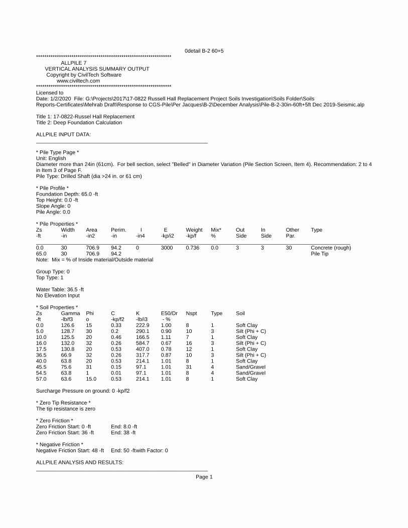
0detail B-2 60+5***************************************************************** ALLPILE 7 VERTICAL ANALYSIS SUMMARY OUTPUT Copyright by CivilTech Software www.civiltech.com *****************************************************************Licensed to Date: 1/2/2020 File: G:\Projects\2017\17-0822 Russell Hall Replacement Project Soils Investigation\Soils Folder\Soils Reports-Certificates\Mehrab Draft\Response to CGS-Pile\Per Jacques\B-2\December Analysis\Pile-B-2-30in-60ft+5ft Dec 2019-Seismic.alp
Title 1: 17-0822-Russel Hall ReplacementTitle 2: Deep Foundation Calculation
ALLPILE INPUT DATA:__________________________________________________________
* Pile Type Page *Unit: EnglishDiameter more than 24in (61cm). For bell section, select "Belled" in Diameter Variation (Pile Section Screen, Item 4). Recommendation: 2 to 4in Item 3 of Page F.Pile Type: Drilled Shaft (dia >24 in. or 61 cm)
* Pile Profile *Foundation Depth: 65.0 -ftTop Height: 0.0 -ftSlope Angle: 0Pile Angle: 0.0
* Pile Properties * Zs Width Area Perim. I E Weight Mix* Out In Other Type -ft -in -in2 -in -in4 -kp/i2 -kp/f % Side Side Par.
__________________________________________________________________________________________________________ 0.0 30 706.9 94.2 0 3000 0.736 0.0 3 3 30 Concrete (rough)
65.0 30 706.9 94.2 Pile TipNote: Mix = % of Inside material/Outside material
Group Type: 0Top Type: 1
Water Table: 36.5 -ftNo Elevation Input
* Soil Properties * Zs Gamma Phi C K E50/Dr Nspt Type Soil -ft -lb/f3 o -kp/f2 -lb/i3 - % 0.0 126.6 15 0.33 222.9 1.00 8 1 Soft Clay 5.0 128.7 30 0.2 290.1 0.90 10 3 Silt (Phi + C)
10.0 125.5 20 0.46 166.5 1.11 7 1 Soft Clay 16.0 132.0 32 0.26 584.7 0.67 16 3 Silt (Phi + C) 17.5 130.8 20 0.53 407.0 0.78 12 1 Soft Clay 36.5 66.9 32 0.26 317.7 0.87 10 3 Silt (Phi + C) 40.0 63.8 20 0.53 214.1 1.01 8 1 Soft Clay 45.5 75.6 31 0.15 97.1 1.01 31 4 Sand/Gravel 54.5 63.8 1 0.01 97.1 1.01 8 4 Sand/Gravel 57.0 63.6 15.0 0.53 214.1 1.01 8 1 Soft Clay
Surcharge Pressure on ground: 0 -kp/f2
* Zero Tip Resistance *The tip resistance is zero
* Zero Friction * Zero Friction Start: 0 -ft End: 8.0 -ft
Zero Friction Start: 36 -ft End: 38 -ft
* Negative Friction * Negative Friction Start: 48 -ft End: 50 -ftwith Factor: 0
ALLPILE ANALYSIS AND RESULTS:__________________________________________________________
Page 1

0detail B-2 60+5
TOTAL LOADS: Vertical Load, Q: 220.0 -kp Vertical Load with Load Factor, Q: 220.0 -kp Vertical Load with Load factor and Pile Cap, Q= 220.0 -kp Load Factor for Vertical Load and Torsion= 1.0 Vertical Loads Supported by Pile Cap: 0 % Load Factor for Vertical Loads: 1.0
PILE PROFILE: Pile Length, L= 65.0 -ft Top Height, H= 0.0 -ft Slope Angle, As= 0 Batter Angle, Ab= 0.00 Batter Factor, Kbat= 1.00 *To consider the influence of different soils below the pile tip, bearing stratum is defined from pile tip extending to 4 Diameter of pile, which is 10.0-ft (Input Page F, Item 3)
SINGLE PILE: Kdown= 0.5 Kup= 0.4 Ka= 1.00
Single Pile Vertical Analysis: Total Ultimate Capacity (Down)= 391.567-kp Total Ultimate Capacity (Up)= 425.172-kp Total Allowable Capacity (Down)= 391.567-kp Total Allowable Capacity (Up)= 425.172-kp
Weight above Ground= 0.00 Total Weight= 39.14-kp *Soil Weight is not included Side Resistance (Down)= 391.567-kp Side Resistance (Up)= 386.031-kp Tip Resistance (Down)= 0.000-kp Tip Resistance (Up)= 0.000-kp Negative Friction, Qneg= 0.000-kp, which has been subtracted from Total Ultimate Capacity (Down) Negative friction does not affect Total Ultimate Capacity (Up) At Work Load= 220.00-kp, Settlement= 0.08481-in At Work Load= 220.00-kp, Secant Stiffness Kqx= 2594.12-kp/-in At Allowable Settlement= 0.500000-in, Capacity= 381.99-kp Work Load, 220.00-kp, OK with the Capacity at Allowable Settlement= 0.50000-in, Capacity= 381.99-kp Work Load, 220.00-kp, OK with the Allowable Capacity (Down)= 391.57-kp
____________________________________________FACTOR OF SAFETY: FSside FStip FSuplif FSweight 1.0 1.0 1.0 1.0
Note: If the program cannot find a result or the result exceeds the upper limit. The result will be displayed as 99999. 1 1 1 1 1
Page 2
MikeM
Text Box
Note: Due to the limitations of the program for the number of soil layers, we used the negative friction option to simulate some of the liquefaction layers. This option eliminates the pile resistance downward but not upward. We subtracted the upward resistance manually using the output data from the detailed report.
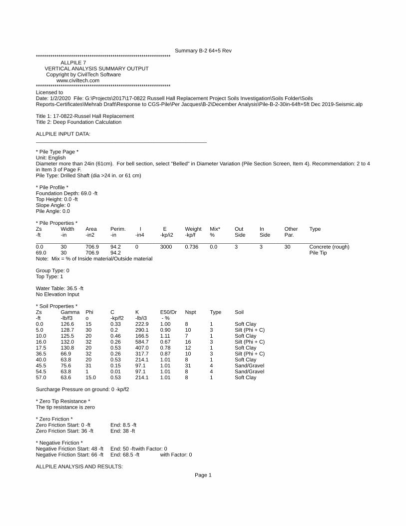
Summary B-2 64+5 Rev***************************************************************** ALLPILE 7 VERTICAL ANALYSIS SUMMARY OUTPUT Copyright by CivilTech Software www.civiltech.com *****************************************************************Licensed to Date: 1/2/2020 File: G:\Projects\2017\17-0822 Russell Hall Replacement Project Soils Investigation\Soils Folder\Soils Reports-Certificates\Mehrab Draft\Response to CGS-Pile\Per Jacques\B-2\December Analysis\Pile-B-2-30in-64ft+5ft Dec 2019-Seismic.alp
Title 1: 17-0822-Russel Hall ReplacementTitle 2: Deep Foundation Calculation
ALLPILE INPUT DATA:__________________________________________________________
* Pile Type Page *Unit: EnglishDiameter more than 24in (61cm). For bell section, select "Belled" in Diameter Variation (Pile Section Screen, Item 4). Recommendation: 2 to 4in Item 3 of Page F.Pile Type: Drilled Shaft (dia >24 in. or 61 cm)
* Pile Profile *Foundation Depth: 69.0 -ftTop Height: 0.0 -ftSlope Angle: 0Pile Angle: 0.0
* Pile Properties * Zs Width Area Perim. I E Weight Mix* Out In Other Type -ft -in -in2 -in -in4 -kp/i2 -kp/f % Side Side Par.
__________________________________________________________________________________________________________ 0.0 30 706.9 94.2 0 3000 0.736 0.0 3 3 30 Concrete (rough)
69.0 30 706.9 94.2 Pile TipNote: Mix = % of Inside material/Outside material
Group Type: 0Top Type: 1
Water Table: 36.5 -ftNo Elevation Input
* Soil Properties * Zs Gamma Phi C K E50/Dr Nspt Type Soil -ft -lb/f3 o -kp/f2 -lb/i3 - % 0.0 126.6 15 0.33 222.9 1.00 8 1 Soft Clay 5.0 128.7 30 0.2 290.1 0.90 10 3 Silt (Phi + C)
10.0 125.5 20 0.46 166.5 1.11 7 1 Soft Clay 16.0 132.0 32 0.26 584.7 0.67 16 3 Silt (Phi + C) 17.5 130.8 20 0.53 407.0 0.78 12 1 Soft Clay 36.5 66.9 32 0.26 317.7 0.87 10 3 Silt (Phi + C) 40.0 63.8 20 0.53 214.1 1.01 8 1 Soft Clay 45.5 75.6 31 0.15 97.1 1.01 31 4 Sand/Gravel 54.5 63.8 1 0.01 97.1 1.01 8 4 Sand/Gravel 57.0 63.6 15.0 0.53 214.1 1.01 8 1 Soft Clay
Surcharge Pressure on ground: 0 -kp/f2
* Zero Tip Resistance *The tip resistance is zero
* Zero Friction * Zero Friction Start: 0 -ft End: 8.5 -ft
Zero Friction Start: 36 -ft End: 38 -ft
* Negative Friction * Negative Friction Start: 48 -ft End: 50 -ftwith Factor: 0 Negative Friction Start: 66 -ft End: 68.5 -ft with Factor: 0
ALLPILE ANALYSIS AND RESULTS:
Page 1

Summary B-2 64+5 Rev__________________________________________________________
TOTAL LOADS: Vertical Load, Q: 240.0 -kp Vertical Load with Load Factor, Q: 240.0 -kp Vertical Load with Load factor and Pile Cap, Q= 240.0 -kp Load Factor for Vertical Load and Torsion= 1.0 Vertical Loads Supported by Pile Cap: 0 % Load Factor for Vertical Loads: 1.0
PILE PROFILE: Pile Length, L= 69.0 -ft Top Height, H= 0.0 -ft Slope Angle, As= 0 Batter Angle, Ab= 0.00 Batter Factor, Kbat= 1.00 *To consider the influence of different soils below the pile tip, bearing stratum is defined from pile tip extending to 4 Diameter of pile, which is 10.0-ft (Input Page F, Item 3)
SINGLE PILE: Kdown= 0.5 Kup= 0.4 Ka= 1.00
Single Pile Vertical Analysis: Total Ultimate Capacity (Down)= 403.040-kp Total Ultimate Capacity (Up)= 457.027-kp Total Allowable Capacity (Down)= 403.040-kp Total Allowable Capacity (Up)= 457.027-kp
Weight above Ground= 0.00 Total Weight= 40.83-kp *Soil Weight is not included Side Resistance (Down)= 403.040-kp Side Resistance (Up)= 416.197-kp Tip Resistance (Down)= 0.000-kp Tip Resistance (Up)= 0.000-kp Negative Friction, Qneg= 0.000-kp, which has been subtracted from Total Ultimate Capacity (Down) Negative friction does not affect Total Ultimate Capacity (Up) At Work Load= 240.00-kp, Settlement= 0.09423-in At Work Load= 240.00-kp, Secant Stiffness Kqx= 2546.89-kp/-in At Allowable Settlement= 0.500000-in, Capacity= 393.40-kp Work Load, 240.00-kp, OK with the Capacity at Allowable Settlement= 0.50000-in, Capacity= 393.40-kp Work Load, 240.00-kp, OK with the Allowable Capacity (Down)= 403.04-kp
____________________________________________FACTOR OF SAFETY: FSside FStip FSuplif FSweight 1.0 1.0 1.0 1.0
Note: If the program cannot find a result or the result exceeds the upper limit. The result will be displayed as 99999. 1 1 1 1 1
Page 2
MikeM
Text Box
Note: Due to the limitations of the program for the number of soil layers, we used the negative friction option to simulate some of the liquefaction layers. This option eliminates the pile resistance downward but not upward. We subtracted the upward resistance manually using the output data from the detailed report.

Summary of CPT-2 49+5 Rev***************************************************************** ALLPILE 7 VERTICAL ANALYSIS SUMMARY OUTPUT Copyright by CivilTech Software www.civiltech.com *****************************************************************Licensed to Date: 12/28/2019 File: G:\Projects\2017\17-0822 Russell Hall Replacement Project Soils Investigation\Soils Folder\Soils Reports-Certificates\Mehrab Draft\Response to CGS-Pile\Per Jacques\CPT-2\December Analysis\Pile-CPT-2-30in-49ft+5ft-Rev 2 Dec 2019-Seismic.alp
Title 1: 17-0822-Russel Hall ReplacementTitle 2: Deep Foundation Calculation
ALLPILE INPUT DATA:__________________________________________________________
* Pile Type Page *Unit: EnglishDiameter more than 24in (61cm). For bell section, select "Belled" in Diameter Variation (Pile Section Screen, Item 4). Recommendation: 2 to 4in Item 3 of Page F.Pile Type: Drilled Shaft (dia >24 in. or 61 cm)
* Pile Profile *Foundation Depth: 54.0 -ftTop Height: 0.0 -ftSlope Angle: 0Pile Angle: 0.0
* Pile Properties * Zs Width Area Perim. I E Weight Mix* Out In Other Type -ft -in -in2 -in -in4 -kp/i2 -kp/f % Side Side Par.
__________________________________________________________________________________________________________ 0.0 30 706.9 94.2 0 3000 0.736 0.0 3 3 30 Concrete (rough)
54.0 30 706.9 94.2 Pile TipNote: Mix = % of Inside material/Outside material
Group Type: 0Top Type: 1
Water Table: 36.5 -ftNo Elevation Input
* Soil Properties * Zs Gamma Phi C K E50/Dr Nspt Type Soil -ft -lb/f3 o -kp/f2 -lb/i3 - % 0.0 126.6 15 0.33 222.9 1.00 8 1 Soft Clay 5.0 128.7 30 0.2 290.1 0.90 10 3 Silt (Phi + C)
10.0 125.5 20 0.46 166.5 1.11 7 1 Soft Clay 16.0 127.1 32 0.26 584.7 0.67 16 3 Silt (Phi + C) 17.5 130.8 20 0.530 407.0 0.78 12 1 Soft Clay 36.5 66.9 32 0.26 317.7 0.87 10 3 Silt (Phi + C) 40.0 63.8 20 0.53 214.1 1.01 8 1 Soft Clay 48.0 66.8 1 0.01 97.1 1.01 8 4 Sand/Gravel 50.0 63.8 15 0.53 313.1 0.87 10 1 Soft Clay 54.5 66.8 1 0.01 97.1 1.01 8 4 Sand/Gravel
Surcharge Pressure on ground: 0 -kp/f2
* Zero Tip Resistance *The tip resistance is zero
* Zero Friction * Zero Friction Start: 0 -ft End: 6.5 -ft
Zero Friction Start: 36 -ft End: 38 -ft
ALLPILE ANALYSIS AND RESULTS:__________________________________________________________
TOTAL LOADS:
Page 1

Summary of CPT-2 49+5 Rev Vertical Load, Q: 173.0 -kp Vertical Load with Load Factor, Q: 173.0 -kp Vertical Load with Load factor and Pile Cap, Q= 173.0 -kp Load Factor for Vertical Load and Torsion= 1.0 Vertical Loads Supported by Pile Cap: 0 % Load Factor for Vertical Loads: 1.0
PILE PROFILE: Pile Length, L= 54.0 -ft Top Height, H= 0.0 -ft Slope Angle, As= 0 Batter Angle, Ab= 0.00 Batter Factor, Kbat= 1.00 *To consider the influence of different soils below the pile tip, bearing stratum is defined from pile tip extending to 4 Diameter of pile, which is 10.0-ft (Input Page F, Item 3)
SINGLE PILE: Kdown= 0.5 Kup= 0.4 Ka= 1.00
Single Pile Vertical Analysis: Total Ultimate Capacity (Down)= 320.597-kp Total Ultimate Capacity (Up)= 334.894-kp Total Allowable Capacity (Down)= 320.597-kp Total Allowable Capacity (Up)= 334.894-kp
Weight above Ground= 0.00 Total Weight= 34.41-kp *Soil Weight is not included Side Resistance (Down)= 320.597-kp Side Resistance (Up)= 300.487-kp Tip Resistance (Down)= 0.000-kp Tip Resistance (Up)= 0.000-kp Negative Friction, Qneg= 0.000-kp, which has been subtracted from Total Ultimate Capacity (Down) Negative friction does not affect Total Ultimate Capacity (Up) At Work Load= 173.00-kp, Settlement= 0.22942-in At Work Load= 173.00-kp, Secant Stiffness Kqx= 754.08-kp/-in At Allowable Settlement= 0.800000-in, Capacity= 314.09-kp Work Load, 173.00-kp, OK with the Capacity at Allowable Settlement= 0.80000-in, Capacity= 314.09-kp Work Load, 173.00-kp, OK with the Allowable Capacity (Down)= 320.60-kp
____________________________________________FACTOR OF SAFETY: FSside FStip FSuplif FSweight 1.0 1.0 1.0 1.0
Note: If the program cannot find a result or the result exceeds the upper limit. The result will be displayed as 99999. 1 1 1 1 1
Page 2
MikeM
Text Box
Note: Due to the limitations of the program for the number of soil layers, we used the negative friction option to simulate some of the liquefaction layers. This option eliminates the pile resistance downward but not upward. We subtracted the upward resistance manually using the output data from the detailed report.

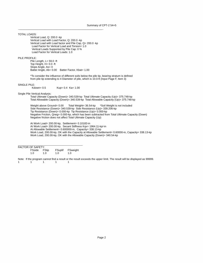
Summary of CPT-2 54+5***************************************************************** ALLPILE 7 VERTICAL ANALYSIS SUMMARY OUTPUT Copyright by CivilTech Software www.civiltech.com *****************************************************************Licensed to Date: 12/28/2019 File: G:\Projects\2017\17-0822 Russell Hall Replacement Project Soils Investigation\Soils Folder\Soils Reports-Certificates\Mehrab Draft\Response to CGS-Pile\Per Jacques\CPT-2\December Analysis\Pile-CPT-2-30in-54ft+5ft Rev Dec 2019-Seismic.alp
Title 1: 17-0822-Russel Hall ReplacementTitle 2: Deep Foundation Calculation
ALLPILE INPUT DATA:__________________________________________________________
* Pile Type Page *Unit: EnglishDiameter more than 24in (61cm). For bell section, select "Belled" in Diameter Variation (Pile Section Screen, Item 4). Recommendation: 2 to 4in Item 3 of Page F.Pile Type: Drilled Shaft (dia >24 in. or 61 cm)
* Pile Profile *Foundation Depth: 59.0 -ftTop Height: 0.0 -ftSlope Angle: 0Pile Angle: 0.0
* Pile Properties * Zs Width Area Perim. I E Weight Mix* Out In Other Type -ft -in -in2 -in -in4 -kp/i2 -kp/f % Side Side Par.
__________________________________________________________________________________________________________ 0.0 30 706.9 94.2 0 3000 0.736 0.0 3 3 30 Concrete (rough)
59.0 30 706.9 94.2 Pile TipNote: Mix = % of Inside material/Outside material
Group Type: 0Top Type: 1
Water Table: 36.5 -ftNo Elevation Input
* Soil Properties * Zs Gamma Phi C K E50/Dr Nspt Type Soil -ft -lb/f3 o -kp/f2 -lb/i3 - % 0.0 126.6 15 0.33 222.9 1.00 8 1 Soft Clay 5.0 128.7 30 0.2 290.1 0.90 10 3 Silt (Phi + C)
10.0 125.5 20 0.46 166.5 1.11 7 1 Soft Clay 16.0 127.1 32 0.26 584.7 0.67 16 3 Silt (Phi + C) 17.5 130.8 20 0.53 407 0.78 12 1 Soft Clay 36.5 66.9 32 0.26 317.7 0.87 10 3 Silt (Phi + C) 40.0 63.8 20 0.53 214.1 1.01 8 1 Soft Clay 48.0 66.8 1 .01 97.1 1.01 8 4 Sand/Gravel 50.0 63.8 15. 0.53 214.1 0.87 10 1 Soft Clay 66.0 66.8 1.0 0.01 214.1 1.01 8 4 Sand/Gravel
Surcharge Pressure on ground: 0 -kp/f2
* Zero Tip Resistance *The tip resistance is zero
* Zero Friction * Zero Friction Start: 0 -ft End: 7 -ft
Zero Friction Start: 36 -ft End: 38 -ft
* Negative Friction * Negative Friction Start: 54.5 -ft End: 57 -ftwith Factor: 0
ALLPILE ANALYSIS AND RESULTS:
Page 1
Summary of CPT-2 54+5__________________________________________________________
TOTAL LOADS: Vertical Load, Q: 200.0 -kp Vertical Load with Load Factor, Q: 200.0 -kp Vertical Load with Load factor and Pile Cap, Q= 200.0 -kp Load Factor for Vertical Load and Torsion= 1.0 Vertical Loads Supported by Pile Cap: 0 % Load Factor for Vertical Loads: 1.0
PILE PROFILE: Pile Length, L= 59.0 -ft Top Height, H= 0.0 -ft Slope Angle, As= 0 Batter Angle, Ab= 0.00 Batter Factor, Kbat= 1.00 *To consider the influence of different soils below the pile tip, bearing stratum is defined from pile tip extending to 4 Diameter of pile, which is 10.0-ft (Input Page F, Item 3)
SINGLE PILE: Kdown= 0.5 Kup= 0.4 Ka= 1.00
Single Pile Vertical Analysis: Total Ultimate Capacity (Down)= 340.539-kp Total Ultimate Capacity (Up)= 375.748-kp Total Allowable Capacity (Down)= 340.539-kp Total Allowable Capacity (Up)= 375.748-kp
Weight above Ground= 0.00 Total Weight= 36.54-kp *Soil Weight is not included Side Resistance (Down)= 340.539-kp Side Resistance (Up)= 339.206-kp Tip Resistance (Down)= 0.000-kp Tip Resistance (Up)= 0.000-kp Negative Friction, Qneg= 0.000-kp, which has been subtracted from Total Ultimate Capacity (Down) Negative friction does not affect Total Ultimate Capacity (Up) At Work Load= 200.00-kp, Settlement= 0.10183-in At Work Load= 200.00-kp, Secant Stiffness Kqx= 1964.11-kp/-in At Allowable Settlement= 0.600000-in, Capacity= 338.13-kp Work Load, 200.00-kp, OK with the Capacity at Allowable Settlement= 0.60000-in, Capacity= 338.13-kp Work Load, 200.00-kp, OK with the Allowable Capacity (Down)= 340.54-kp
____________________________________________FACTOR OF SAFETY: FSside FStip FSuplif FSweight 1.0 1.0 1.0 1.0
Note: If the program cannot find a result or the result exceeds the upper limit. The result will be displayed as 99999. 1 1 1 1 1
Page 2
MikeM
Text Box
Note: Due to the limitations of the program for the number of soil layers, we used the negative friction option to simulate some of the liquefaction layers. This option eliminates the pile resistance downward but not upward. We subtracted the upward resistance manually using the output data from the detailed report.

Summary of CPT-2 60+5 Rev***************************************************************** ALLPILE 7 VERTICAL ANALYSIS SUMMARY OUTPUT Copyright by CivilTech Software www.civiltech.com *****************************************************************Licensed to Date: 12/29/2019 File: G:\Projects\2017\17-0822 Russell Hall Replacement Project Soils Investigation\Soils Folder\Soils Reports-Certificates\Mehrab Draft\Response to CGS-Pile\Per Jacques\CPT-2\December Analysis\Pile-CPT-2-30in-60ft+5ft Rev Dec
2019-Seismic.alp 1.0
Title 1: 17-0822-Russel Hall ReplacementTitle 2: Deep Foundation Calculation
ALLPILE INPUT DATA:__________________________________________________________
* Pile Type Page *Unit: EnglishDiameter more than 24in (61cm). For bell section, select "Belled" in Diameter Variation (Pile Section Screen, Item 4). Recommendation: 2 to 4in Item 3 of Page F.Pile Type: Drilled Shaft (dia >24 in. or 61 cm)
* Pile Profile *Foundation Depth: 65.0 -ftTop Height: 0.0 -ftSlope Angle: 0Pile Angle: 0.0
* Pile Properties * Zs Width Area Perim. I E Weight Mix* Out In Other Type -ft -in -in2 -in -in4 -kp/i2 -kp/f % Side Side Par.
__________________________________________________________________________________________________________ 0.0 30 706.9 94.2 0 3000 0.736 0.0 3 3 30 Concrete (rough)
65.0 30 706.9 94.2 Pile TipNote: Mix = % of Inside material/Outside material
Group Type: 0Top Type: 1
Water Table: 36.5 -ftNo Elevation Input
* Soil Properties * Zs Gamma Phi C K E50/Dr Nspt Type Soil -ft -lb/f3 o -kp/f2 -lb/i3 - % 0.0 126.6 15 0.33 222.9 1.00 8 1 Soft Clay 5.0 128.7 30 .2 290.1 0.90 10 3 Silt (Phi + C)
10.0 125.5 20 .46 166.5 1.11 7 1 Soft Clay 16.0 127.1 32 0.26 584.7 0.67 8 3 Silt (Phi + C) 17.5 130.8 20 0.53 407 0.78 16 1 Soft Clay 36.5 66.9 32 0.26 317.7 0.87 12 3 Silt (Phi + C) 40.0 63.8 20 0.53 214.1 1.01 10 1 Soft Clay 48.0 66.8 1 0.01 97.1 1.01 8 4 Sand/Gravel 50.0 63.8 15 0.53 214.1 0.87 10 1 Soft Clay 66.0 66.8 1 0.01 214.1 1.01 8 4 Sand/Gravel
Surcharge Pressure on ground: 0 -kp/f2
* Zero Tip Resistance *The tip resistance is zero
* Zero Friction * Zero Friction Start: 0 -ft End: 6 -ft
Zero Friction Start: 36 -ft End: 38 -ft
* Negative Friction * Negative Friction Start: 54.5 -ft End: 57 -ftwith Factor: 0
ALLPILE ANALYSIS AND RESULTS:
Page 1

Summary of CPT-2 60+5 Rev__________________________________________________________
TOTAL LOADS: Vertical Load, Q: 220.0 -kp Vertical Load with Load Factor, Q: 220.0 -kp Vertical Load with Load factor and Pile Cap, Q= 220.0 -kp Load Factor for Vertical Load and Torsion= 1.0 Vertical Loads Supported by Pile Cap: 0 % Load Factor for Vertical Loads: 1.0
PILE PROFILE: Pile Length, L= 65.0 -ft Top Height, H= 0.0 -ft Slope Angle, As= 0 Batter Angle, Ab= 0.00 Batter Factor, Kbat= 1.00 *To consider the influence of different soils below the pile tip, bearing stratum is defined from pile tip extending to 4 Diameter of pile, which is 10.0-ft (Input Page F, Item 3)
SINGLE PILE: Kdown= 0.5 Kup= 0.4 Ka= 1.00
Single Pile Vertical Analysis: Total Ultimate Capacity (Down)= 397.379-kp Total Ultimate Capacity (Up)= 429.381-kp Total Allowable Capacity (Down)= 397.379-kp Total Allowable Capacity (Up)= 429.381-kp
Weight above Ground= 0.00 Total Weight= 39.14-kp *Soil Weight is not included Side Resistance (Down)= 397.379-kp Side Resistance (Up)= 390.240-kp Tip Resistance (Down)= 0.000-kp Tip Resistance (Up)= 0.000-kp Negative Friction, Qneg= 0.000-kp, which has been subtracted from Total Ultimate Capacity (Down) Negative friction does not affect Total Ultimate Capacity (Up) At Work Load= 220.00-kp, Settlement= 0.20003-in At Work Load= 220.00-kp, Secant Stiffness Kqx= 1099.86-kp/-in At Allowable Settlement= 0.600000-in, Capacity= 385.16-kp Work Load, 220.00-kp, OK with the Capacity at Allowable Settlement= 0.60000-in, Capacity= 385.16-kp Work Load, 220.00-kp, OK with the Allowable Capacity (Down)= 397.38-kp
____________________________________________FACTOR OF SAFETY: FSside FStip FSuplif FSweight 1.0 1.0 1.0 1.0
Note: If the program cannot find a result or the result exceeds the upper limit. The result will be displayed as 99999. 1 1 1 1 1
Page 2
MikeM
Text Box
Note: Due to the limitations of the program for the number of soil layers, we used the negative friction option to simulate some of the liquefaction layers. This option eliminates the pile resistance downward but not upward. We subtracted the upward resistance manually using the output data from the detailed report.

Summary of CPT-2 60+5 -4.5' of free surface***************************************************************** ALLPILE 7 VERTICAL ANALYSIS SUMMARY OUTPUT Copyright by CivilTech Software www.civiltech.com *****************************************************************Licensed to Date: 12/29/2019 File: G:\Projects\2017\17-0822 Russell Hall Replacement Project Soils Investigation\Soils Folder\Soils Reports-Certificates\Mehrab Draft\Response to CGS-Pile\Per Jacques\CPT-2\December Analysis\Pile-CPT-2-30in-60ft+5ft -4.5 of free
surrfaceRev Dec 2019-Seismic.alp 1.0
Title 1: 17-0822-Russel Hall ReplacementTitle 2: Deep Foundation Calculation
ALLPILE INPUT DATA:__________________________________________________________
* Pile Type Page *Unit: EnglishDiameter more than 24in (61cm). For bell section, select "Belled" in Diameter Variation (Pile Section Screen, Item 4). Recommendation: 2 to 4in Item 3 of Page F.Pile Type: Drilled Shaft (dia >24 in. or 61 cm)
* Pile Profile *Foundation Depth: 65.0 -ftTop Height: 0.0 -ftSlope Angle: 0Pile Angle: 0.0
* Pile Properties * Zs Width Area Perim. I E Weight Mix* Out In Other Type -ft -in -in2 -in -in4 -kp/i2 -kp/f % Side Side Par.
______________________________________________________________________________________________________________ 0.0 30 706.9 94.2 0 3000 0.736 0.0 3 3 30 Concrete (rough)
65.0 30 706.9 94.2 Pile TipNote: Mix = % of Inside material/Outside material
Group Type: 0Top Type: 1
Water Table: 36.5 -ftNo Elevation Input
* Soil Properties * Zs Gamma Phi C K E50/Dr Nspt Type Soil -ft -lb/f3 o -kp/f2 -lb/i3 - % 0.0 126.6 15 0.33 222.9 1.00 8 1 Soft Clay 5.0 128.7 30 .2 290.1 0.90 10 3 Silt (Phi + C)
10.0 125.5 20 .46 166.5 1.11 7 1 Soft Clay 16.0 127.1 32 0.26 584.7 0.67 8 3 Silt (Phi + C) 17.5 130.8 20 0.53 407 0.78 16 1 Soft Clay 36.5 66.9 32 0.26 317.7 0.87 12 3 Silt (Phi + C) 40.0 63.8 20 0.53 214.1 1.01 10 1 Soft Clay 48.0 66.8 1 0.01 97.1 1.01 8 4 Sand/Gravel 50.0 63.8 15 0.53 214.1 0.87 10 1 Soft Clay 66.0 66.8 1 0.01 214.1 1.01 8 4 Sand/Gravel
Surcharge Pressure on ground: 0 -kp/f2
* Zero Tip Resistance *The tip resistance is zero
* Zero Friction * Zero Friction Start: 0 -ft End: 4.5 -ft
Zero Friction Start: 36 -ft End: 38 -ft
* Negative Friction * Negative Friction Start: 54.5 -ft End: 57 -ftwith Factor: 0
ALLPILE ANALYSIS AND RESULTS:
Page 1

Summary of CPT-2 60+5 -4.5' of free surface__________________________________________________________
TOTAL LOADS: Vertical Load, Q: 227.0 -kp Vertical Load with Load Factor, Q: 227.0 -kp Vertical Load with Load factor and Pile Cap, Q= 227.0 -kp Load Factor for Vertical Load and Torsion= 1.0 Vertical Loads Supported by Pile Cap: 0 % Load Factor for Vertical Loads: 1.0
PILE PROFILE: Pile Length, L= 65.0 -ft Top Height, H= 0.0 -ft Slope Angle, As= 0 Batter Angle, Ab= 0.00 Batter Factor, Kbat= 1.00 *To consider the influence of different soils below the pile tip, bearing stratum is defined from pile tip extending to 4 Diameter of pile, which is 10.0-ft (Input Page F, Item 3)
SINGLE PILE: Kdown= 0.5 Kup= 0.4 Ka= 1.00
Single Pile Vertical Analysis: Total Ultimate Capacity (Down)= 401.923-kp Total Ultimate Capacity (Up)= 433.614-kp Total Allowable Capacity (Down)= 401.923-kp Total Allowable Capacity (Up)= 433.614-kp
Weight above Ground= 0.00 Total Weight= 39.14-kp *Soil Weight is not included Side Resistance (Down)= 401.923-kp Side Resistance (Up)= 394.472-kp Tip Resistance (Down)= 0.000-kp Tip Resistance (Up)= 0.000-kp Negative Friction, Qneg= 0.000-kp, which has been subtracted from Total Ultimate Capacity (Down) Negative friction does not affect Total Ultimate Capacity (Up) At Work Load= 227.00-kp, Settlement= 0.20733-in At Work Load= 227.00-kp, Secant Stiffness Kqx= 1094.86-kp/-in At Allowable Settlement= 0.600000-in, Capacity= 389.02-kp Work Load, 227.00-kp, OK with the Capacity at Allowable Settlement= 0.60000-in, Capacity= 389.02-kp Work Load, 227.00-kp, OK with the Allowable Capacity (Down)= 401.92-kp
____________________________________________FACTOR OF SAFETY: FSside FStip FSuplif FSweight 1.0 1.0 1.0 1.0
Note: If the program cannot find a result or the result exceeds the upper limit. The result will be displayed as 99999. 1 1 1 1 1
Page 2
MikeM
Text Box
Note: Due to the limitations of the program for the number of soil layers, we used the negative friction option to simulate some of the liquefaction layers. This option eliminates the pile resistance downward but not upward. We subtracted the upward resistance manually using the output data from the detailed report.

Summary of CPT-2 64+5***************************************************************** ALLPILE 7 VERTICAL ANALYSIS SUMMARY OUTPUT Copyright by CivilTech Software www.civiltech.com *****************************************************************Licensed to Date: 12/30/2019 File: G:\Projects\2017\17-0822 Russell Hall Replacement Project Soils Investigation\Soils Folder\Soils Reports-Certificates\Mehrab Draft\Response to CGS-Pile\Per Jacques\CPT-2\December Analysis\Pile-CPT-2-30in-64ft+5ft Dec
2019-Seismic.alp 1.0
Title 1: 17-0822-Russel Hall ReplacementTitle 2: Deep Foundation Calculation
ALLPILE INPUT DATA:__________________________________________________________
* Pile Type Page *Unit: EnglishDiameter more than 24in (61cm). For bell section, select "Belled" in Diameter Variation (Pile Section Screen, Item 4). Recommendation: 2 to 4in Item 3 of Page F.Pile Type: Drilled Shaft (dia >24 in. or 61 cm)
* Pile Profile *Foundation Depth: 69.0 -ftTop Height: 0.0 -ftSlope Angle: 0Pile Angle: 0.0
* Pile Properties * Zs Width Area Perim. I E Weight Mix* Out In Other Type -ft -in -in2 -in -in4 -kp/i2 -kp/f % Side Side Par.
_________________________________________________________________________________________________________ 0.0 30 706.9 94.2 0 3000 0.736 0.0 3 3 30 Concrete (rough)
69.0 30 706.9 94.2 Pile TipNote: Mix = % of Inside material/Outside material
Group Type: 0Top Type: 1
Water Table: 36.5 -ftNo Elevation Input
* Soil Properties * Zs Gamma Phi C K E50/Dr Nspt Type Soil -ft -lb/f3 o -kp/f2 -lb/i3 - % 0.0 126.6 15 0.33 222.9 1.00 8 1 Soft Clay 5.0 128.7 30 .2 290.1 0.90 10 3 Silt (Phi + C)
10.0 125.5 20 .46 166.5 1.11 7 1 Soft Clay 16.0 127.1 32 0.26 584.7 0.67 8 3 Silt (Phi + C) 17.5 130.8 20 0.53 407 0.78 16 1 Soft Clay 36.5 66.9 32 0.26 317.7 0.87 12 3 Silt (Phi + C) 40.0 63.8 20 0.53 214.1 1.01 10 1 Soft Clay 48.0 66.8 1 0.01 97.1 1.01 8 4 Sand/Gravel 50.0 63.8 15 0.53 214.1 0.87 10 1 Soft Clay 71.0 63.6 15 0.53 214.1 0.87 10 1 Soft Clay
Surcharge Pressure on ground: 0 -kp/f2
* Zero Tip Resistance *The tip resistance is zero
* Zero Friction * Zero Friction Start: 0 -ft End: 8.5 -ft
Zero Friction Start: 36 -ft End: 38 -ft
* Negative Friction * Negative Friction Start: 54.5 -ft End: 57 -ftwith Factor: 0
Negative Friction Start: 66 -ft End: 68.5 -ft with Factor: 0
Page 1
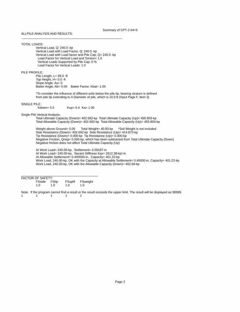
Summary of CPT-2 64+5ALLPILE ANALYSIS AND RESULTS:__________________________________________________________
TOTAL LOADS: Vertical Load, Q: 240.0 -kp Vertical Load with Load Factor, Q: 240.0 -kp Vertical Load with Load factor and Pile Cap, Q= 240.0 -kp Load Factor for Vertical Load and Torsion= 1.0 Vertical Loads Supported by Pile Cap: 0 % Load Factor for Vertical Loads: 1.0
PILE PROFILE: Pile Length, L= 69.0 -ft Top Height, H= 0.0 -ft Slope Angle, As= 0 Batter Angle, Ab= 0.00 Batter Factor, Kbat= 1.00 *To consider the influence of different soils below the pile tip, bearing stratum is defined from pile tip extending to 4 Diameter of pile, which is 10.0-ft (Input Page F, Item 3)
SINGLE PILE: Kdown= 0.5 Kup= 0.4 Ka= 1.00
Single Pile Vertical Analysis: Total Ultimate Capacity (Down)= 402.692-kp Total Ultimate Capacity (Up)= 455.803-kp Total Allowable Capacity (Down)= 402.692-kp Total Allowable Capacity (Up)= 455.803-kp
Weight above Ground= 0.00 Total Weight= 40.83-kp *Soil Weight is not included Side Resistance (Down)= 402.692-kp Side Resistance (Up)= 414.973-kp Tip Resistance (Down)= 0.000-kp Tip Resistance (Up)= 0.000-kp Negative Friction, Qneg= 0.000-kp, which has been subtracted from Total Ultimate Capacity (Down) Negative friction does not affect Total Ultimate Capacity (Up) At Work Load= 240.00-kp, Settlement= 0.09187-in At Work Load= 240.00-kp, Secant Stiffness Kqx= 2612.38-kp/-in At Allowable Settlement= 0.400000-in, Capacity= 401.22-kp Work Load, 240.00-kp, OK with the Capacity at Allowable Settlement= 0.40000-in, Capacity= 401.22-kp Work Load, 240.00-kp, OK with the Allowable Capacity (Down)= 402.69-kp
____________________________________________FACTOR OF SAFETY: FSside FStip FSuplif FSweight 1.0 1.0 1.0 1.0
Note: If the program cannot find a result or the result exceeds the upper limit. The result will be displayed as 99999. 1 1 1 1 1
Page 2
MikeM
Text Box
Note: Due to the limitations of the program for the number of soil layers, we used the negative friction option to simulate some of the liquefaction layers. This option eliminates the pile resistance downward but not upward. We subtracted the upward resistance manually using the output data from the detailed report.

![4 Pile Cap Design [Civilax.com]](https://static.fdocuments.in/doc/165x107/563db860550346aa9a9320bb/4-pile-cap-design-civilaxcom.jpg)