1 - Web viewIt Refer to ACI chapter 7 clause 7.7.1. Table 3.1 Cover to Reinforcement. ... 9.1.Pile...
74
Table of Content s 1. GENERAL MARTIN OKE..................................................2 1.1. SCOPE...........................................................2 1.2. LANGUAGE.........................................................2 1.3. UNITS OF MEASUREMENTS..............................................2 1.4. CODE AND STANDARDS................................................2 1.4.1. Design Code................................................................................................................. 2 1.4.2. Materials Codes and Standards................................................................................. 2 2. MATERIAL............................................................3 2.1. GENERAL......................................................... 3 2.2. MATERIALS AND STANDARDS............................................3 3. MATERIAL PROPERTIES.................................................3 3.1. STRUCTURAL CONCRETE...............................................3 3.2. COVER TO REINFORCEMENT.............................................3 3.3. REINFORCING BAR...................................................4 3.4. ALLOWABLE BEARING CAPACITY.........................................4 4. STRUCTURAL DESIGN...................................................6 4.1. GENERAL......................................................... 6 4.2. OUTLINE......................................................... 6 4.3. METHOD OF ANALYSIS................................................7 4.4. ANALYSIS SOFTWARE.................................................7 4.5. STRUCTURAL MODEL..................................................7 4.6. LOAD INPUT.......................................................8 4.6.1. Purlin Design............................................................................................................... 8 4.6.2. Wind Load X-Direction.............................................................................................. 12 4.6.3. Wind Y-Direction....................................................................................................... 13 5. LOADS AND LOADS COMBINATIONS.......................................14 5.1. DEAD LOAD (DL).................................................14 5.2. LIVE LOAD (LL).................................................14 5.3. SEISMIC LOAD (EL)...............................................14 5.4. COMBINATION OF LOAD..............................................17 6. UPPER STRUCTURE ANALYSIS...........................................18 6.1. CHECK OF DISPLACEMENT.............................................19 6.2. STORY DRIFT.....................................................20 6.3. STRUCTURE DESIGN.................................................21 6.3.1. Stress Ratio................................................................................................................ 21 7. STEEL CONNECTION AND REINFORCEMENT DESIGN..........................22 8. DESIGN SLAB AND TIE BEAM...........................................43 8.1. ............................................ SLAB REINFORCEMENT 43 Calculation Report for Starch Warehouse Page 1 of 57
Transcript of 1 - Web viewIt Refer to ACI chapter 7 clause 7.7.1. Table 3.1 Cover to Reinforcement. ... 9.1.Pile...
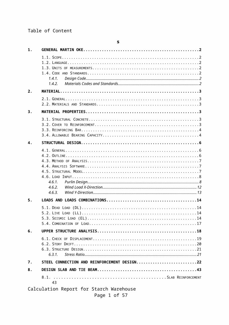
Table of Content
s
1. GENERAL MARTIN OKE.................................................................................................................... 2
1.1. SCOPE................................................................................................................................................21.2. LANGUAGE..........................................................................................................................................21.3. UNITS OF MEASUREMENTS......................................................................................................................21.4. CODE AND STANDARDS..........................................................................................................................2
1.4.1. Design Code................................................................................................................21.4.2. Materials Codes and Standards..........................................................................2
2. MATERIAL....................................................................................................................................... 3
2.1. GENERAL.............................................................................................................................................32.2. MATERIALS AND STANDARDS..................................................................................................................3
3. MATERIAL PROPERTIES.................................................................................................................... 3
3.1. STRUCTURAL CONCRETE.........................................................................................................................33.2. COVER TO REINFORCEMENT....................................................................................................................33.3. REINFORCING BAR................................................................................................................................43.4. ALLOWABLE BEARING CAPACITY..............................................................................................................4
4. STRUCTURAL DESIGN....................................................................................................................... 6
4.1. GENERAL.............................................................................................................................................64.2. OUTLINE.............................................................................................................................................64.3. METHOD OF ANALYSIS...........................................................................................................................74.4. ANALYSIS SOFTWARE.............................................................................................................................74.5. STRUCTURAL MODEL.............................................................................................................................74.6. LOAD INPUT.........................................................................................................................................8
4.6.1. Purlin Design....................................................................................................................84.6.2. Wind Load X-Direction...................................................................................................124.6.3. Wind Y-Direction............................................................................................................13
5. LOADS AND LOADS COMBINATIONS..............................................................................................14
5.1. DEAD LOAD (DL)................................................................................................................................145.2. LIVE LOAD (LL)..................................................................................................................................145.3. SEISMIC LOAD (EL).............................................................................................................................145.4. COMBINATION OF LOAD.......................................................................................................................17
6. UPPER STRUCTURE ANALYSIS........................................................................................................18
6.1. CHECK OF DISPLACEMENT.....................................................................................................................196.2. STORY DRIFT......................................................................................................................................206.3. STRUCTURE DESIGN.............................................................................................................................21
6.3.1. Stress Ratio...............................................................................................................21
7. STEEL CONNECTION AND REINFORCEMENT DESIGN.......................................................................22
8. DESIGN SLAB AND TIE BEAM.......................................................................................................... 43
8.1. SLAB REINFORCEMENT.........................................................................................................................438.2. SLAB THICKENING REINFORCEMENT........................................................................................................478.3. DESIGN TIE BEAM 400 X 700...............................................................................................................49
9. DESIGN FOUNDATION................................................................................................................... 53
9.1. PILE CAP WITH 1 PILE..........................................................................................................................539.2. PILE CAP WITH 2 PILES........................................................................................................................559.3. PILE CAP WITH 3 PILES........................................................................................................................57
Calculation Report for Starch Warehouse Page 1 of 57
1. GENERAL MARTIN OKE
1.1. Scope This calculation document covers the analysis and design for Starch Warehouse Building for Sunrise Project.
1.2. LanguageAll drawings, calculations, and documents shall be written in English.
1.3. Units of measurementsUnits of measurement in design shall be in SI systems.Length : mm, mArea : mm², m²Force : kg, ton, N, kNMoment : kgm, tonm, kNm, NmmPressure, Stress : kg/cm2, N/mm2
1.4. Code and StandardsIn principle, the following codes and standards shall be applied.
1.4.1. Design Code Local Codes:1) SNI 2847-2013 Indonesian Concrete Codes2) SNI 1726-2012 Indonesian Earthquake Load3) SNI 1727-2013 Indonesian Code for Building Loading DesignInternational Codes:1) AISC American Institute of Steel Construction2) ACI 318-08 Building Code Requirements for Structural
Concrete and Commentary 3) ASCE 7 - 02 Minimum Design Load and Load Combination
Calculation Report for Starch Warehouse Page 2 of 57
for Buildings and Other Structure
1.4.2. Materials Codes and Standards1) SNI Standard Nasional Indonesia2) ASTM American Society for Testing and Materials3) ANSI American National Standards Institute4) JIS Japanese Industrial Standard
2. MATERIAL
2.1. GeneralMaterials need to fulfill the requirement of the codes and standards as listed in below shall be used.As for the materials other than specified below such as steel, coarse and fine aggregate, brick, concrete block, architectural finish materials, etc. Locally available materials will be used and provided which are suitable for the specific use in quality and quantity.
2.2. Materials and Standards(A) Structural Steel ASTM A36(B) Structural Concrete ACI 318-08, SNI 15-2049-2004
(C) Reinforcing Bar SNI 07-2052-2002(D) Bolts:
a. High Strength Bolts ASTM A325b. Common Bolts ASTM A307 c. Anchor Bolts ASTM A307
(E) Welding Electrodes AWS A5.1/D1.1 or JIS Z3211, or equivalent
3. MATERIAL PROPERTIES3.1. Structural Concrete
Calculation Report for Starch Warehouse Page 3 of 57
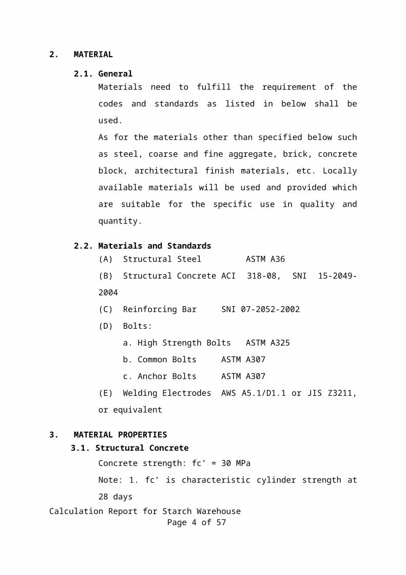
Concrete strength: fc’ = 30 MPa
Note: 1. fc’ is characteristic cylinder strength at 28 days
Note: 2. fc’ is minimum compressive strength
Elastic modulus of concrete: Ec = 4700 √ f ' cSpecific gravity of concrete c =
24 KN/m3
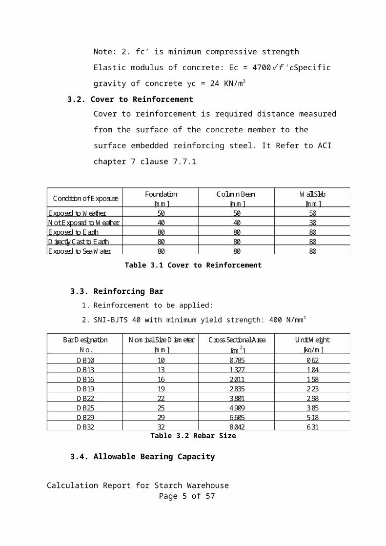
3.2. Cover to ReinforcementCover to reinforcement is required distance measured from the surface of the
concrete member to the surface embedded reinforcing steel. It Refer to ACI
chapter 7 clause 7.7.1
Foundation Column Beam Wall Slab[mm] [mm] [mm]
Exposed to Weather 50 50 50Not Exposed to Weather 40 40 30Exposed to Earth 80 80 80Directly Cast to Earth 80 80 80Exposed to Sea Water 80 80 80
Condition of Exposure
Table 3.1 Cover to Reinforcement
3.3. Reinforcing Bar1. Reinforcement to be applied:
2. SNI-BJTS 40 with minimum yield strength: 400 N/mm2
Bar Designation Nominal Size Diameter Cross Sectional Area Unit Weight No. [mm] [cm2] [kg/ m]
DB10 10 0.785 0.62DB13 13 1.327 1.04DB16 16 2.011 1.58DB19 19 2.835 2.23DB22 22 3.801 2.98DB25 25 4.909 3.85DB29 29 6.605 5.18DB32 32 8.042 6.31
Table 3.2 Rebar Size
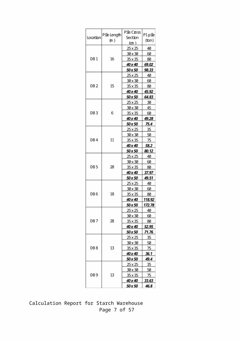
3.4. Allowable Bearing CapacityBased on the soil investigation report by PT. Solefound Sakti, the capacity of
some types of pile is in the following table.
Calculation Report for Starch Warehouse Page 4 of 57
LocationPile Length
(m)
Pile Cross Section
(cm)
P1 pile (ton)
25 x 25 4030 x 30 6035 x 35 8040 x 40 69.0250 x 50 98.3325 x 25 4030 x 30 6035 x 35 8040 x 40 45.9250 x 50 64.8325 x 25 3030 x 30 4535 x 35 6040 x 40 49.2850 x 50 75.425 x 25 3530 x 30 5035 x 35 7540 x 40 58.250 x 50 80.1225 x 25 4030 x 30 6035 x 35 8040 x 40 37.9750 x 50 49.5125 x 25 4030 x 30 6035 x 35 8040 x 40 118.9250 x 50 172.7825 x 25 4030 x 30 6035 x 35 8040 x 40 52.9550 x 50 71.7625 x 25 3530 x 30 5035 x 35 7540 x 40 36.150 x 50 49.425 x 25 3530 x 30 5035 x 35 7540 x 40 33.6350 x 50 46.8
15
16
DB 3
DB 2
DB 1
13
13
28
18
28
11
6
DB 9
DB 8
DB 7
DB 6
DB 5
DB 4
Table 3.3 Allowable Bearing Capacity
Calculation Report for Starch Warehouse Page 5 of 57
*.Notes:
1. Pile capacity for pile with 40 x 40 and 50 x 50 cross section is not provided by PT. Solefound Sakti.
2. Pile capacity for pile with 40 x 40 and 50 x 50 cross section is prepared by BITA.
4. STRUCTURAL DESIGN
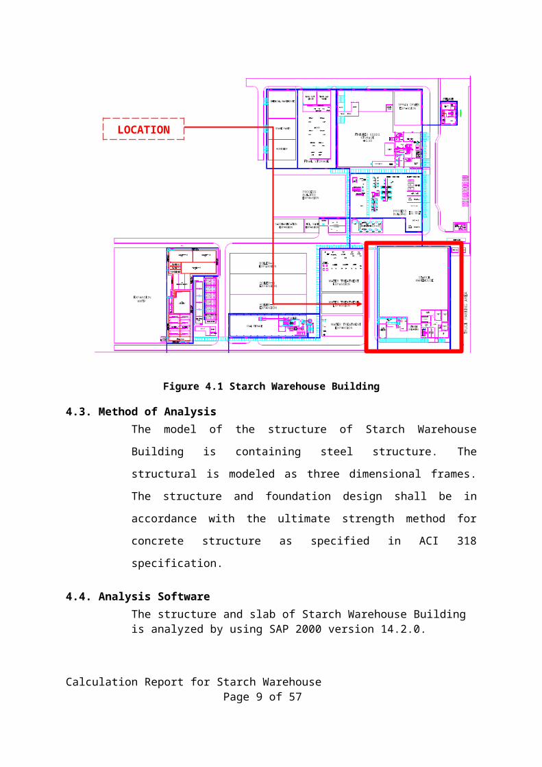
4.1. GeneralThe Starch Warehouse structure is a space frames consist of beam and columns which are supported by pile foundation.
4.2. Outline The summary of the mentioned building is as follow:1. Name of building : Starch Warehouse Building 2. Building Size : 60 m x 78 m 3. Height : approx. 12 m 4. Building area : 4680 m2 5. Structural type : steel structure
Figure 4.1 Starch Warehouse Building Calculation Report for Starch Warehouse Page 6 of 57
LOCATION
4.3. Method of AnalysisThe model of the structure of Starch Warehouse Building is containing steel structure. The structural is modeled as three dimensional frames. The structure and foundation design shall be in accordance with the ultimate strength method for concrete structure as specified in ACI 318 specification.
4.4. Analysis Software The structure and slab of Starch Warehouse Building is analyzed by using SAP 2000 version 14.2.0.
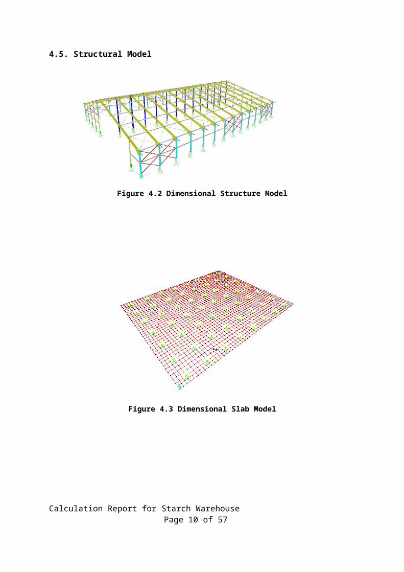
4.5. Structural Model
Figure 4.2 Dimensional Structure Model
Calculation Report for Starch Warehouse Page 7 of 57
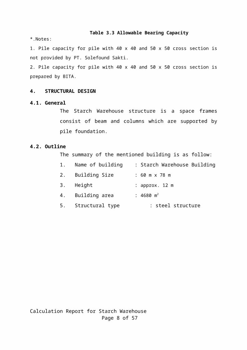
Figure 4.3 Dimensional Slab Model
Calculation Report for Starch Warehouse Page 8 of 57
4.6. Load Input
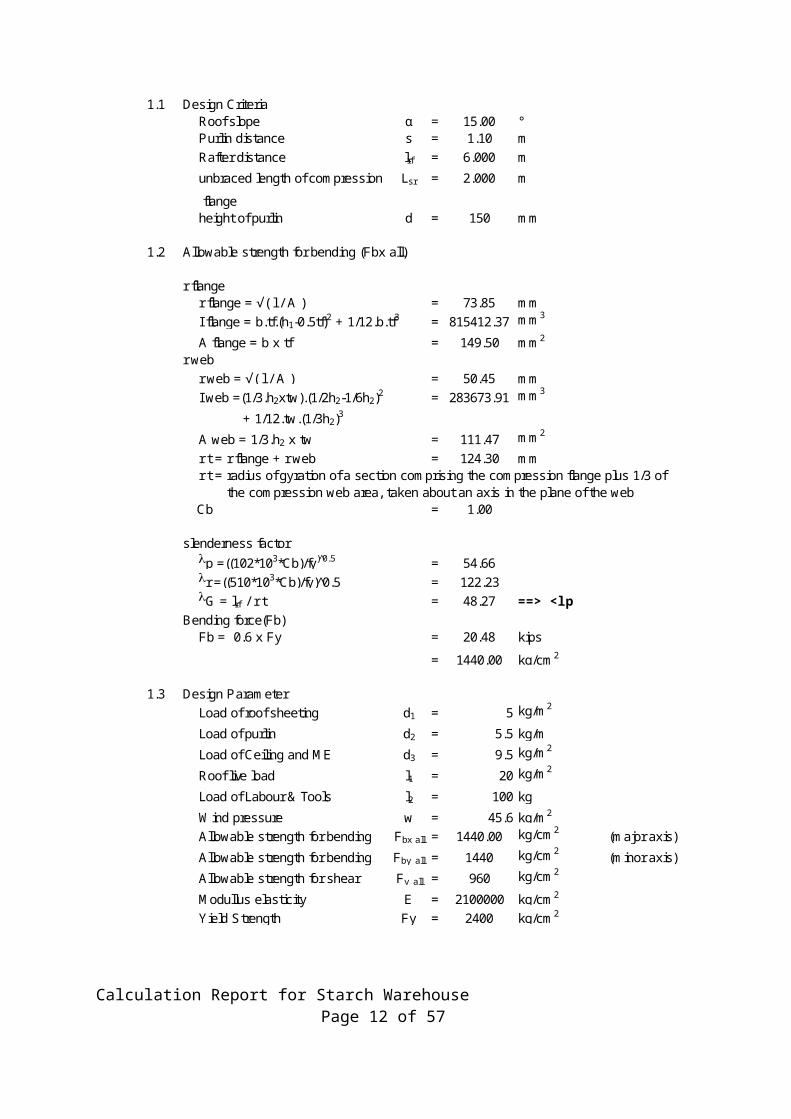
4.6.1. Purlin Design1.1 Design Criteria
Roof slope α = 15.00 ° Purlin distance s = 1.10 mRafter distance lrf = 6.000 munbraced length of compression Lsr = 2.000 m
flangeheight of purlin d = 150 mm
1.2 Allowable strength for bending (Fbx all)
r flanger flange = √( l / A ) = 73.85 mmI flange = b.tf.(h1-0.5tf)2 + 1/12.b.tf3 = 815412.37 mm3
A flange = b x tf = 149.50 mm2
r webr web = √( l / A ) = 50.45 mmI web =(1/3.h2xtw).(1/2h2-1/6h2)2 = 283673.91 mm3
+ 1/12.tw.(1/3h2)3
A web = 1/3.h2 x tw = 111.47 mm2
r t = r flange + r web = 124.30 mmr t = radius of gyration of a section comprising the compression flange plus 1/3 of the compression web area, taken about an axis in the plane of the webCb = 1.00
slenderness factorlp =((102*103*Cb)/fy) 0̂.5 = 54.66lr =((510*103*Cb)/fy)^0.5 = 122.23lG = lrf / r t = 48.27 ==> <l p
Bending force(Fb)Fb = 0.6 x Fy = 20.48 kips
= 1440.00 kg/cm2
1.3 Design ParameterLoad of roof sheeting d1 = 5 kg/m2
Load of purlin d2 = 5.5 kg/mLoad of Ceiling and ME d3 = 9.5 kg/m2
Roof live load l1 = 20 kg/m2
Load of Labour & Tools l2 = 100 kg
Wind pressure w = 45.6 kg/m2
Allowable strength for bending Fbx all = 1440.00 kg/cm2 (major axis)
Allowable strength for bending Fby all = 1440 kg/cm2 (minor axis)Allowable strength for shear Fv all = 960 kg/cm2
Modullus elasticity E = 2100000 kg/cm2
Yield Strength Fy = 2400 kg/cm2
Calculation Report for Starch Warehouse Page 9 of 57
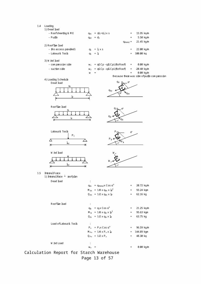
1.4 Loading1) Dead load
- Roof sheeting & ME qd1 = (d1+d3) x s = 15.95 kg/m
- Purlin qd2 = d2 = 5.50 kg/m
qdtotal = 21.45 kg/m2) Roof live load
- (No access provided) ql = l1 x s = 22.00 kg/m
- Labour & Tools ql = l2 = 100.00 kg
3) Wind load- compression side w1 = qGCp - qiGCpi (for Roof) = 0.00 kg/m
- suction side w2 = qGCp - qiGCpi (for Roof) = -20.40 kg/mw = = 0.00 kg/m
Because there was side of purlin compression4) Loading Schedule
Dead load
Roof live loadql
Labour & Tools Pl
Wind loadw
1.5 Internal Force1) Internal force ┴ roof plan
Dead load :
qdx = qdtotal x Cos αo = 20.72 kg/m
Mdx = 1/8 x qdx x lrf 2 = 93.24 kgm
Qdx = 1/2 x qdx x lrf = 62.16 kg
Roof live load :
qlx = ql x Cos αo = 21.25 kg/m
Mlx = 1/8 x qlx x lrf 2 = 95.63 kgm
Qlx = 1/2 x qlx x lrf = 63.75 kg
Load of Labour & Tools :Px = Pl x Cos αo = 96.59 kg/m
MPx = 1/4 x Px x lrf = 144.89 kgm
QPx = 1/2 x Px = 48.30 kg
Wind Load :wx = = 0.00 kg/m
Mwx = 1/8 x wx x lrf 2 = 0.00 kgmQwx = 1/2 x wx x lrf = 0.00 kg
αo qdx
qdy
qd αo
ao q lx
q ly
q l αo
lkd
lkd
ao Plx
Ply
Pl αo
ao
Wx
Wy
qd
lrf
ql
lrf
Calculation Report for Starch Warehouse Page 10 of 57
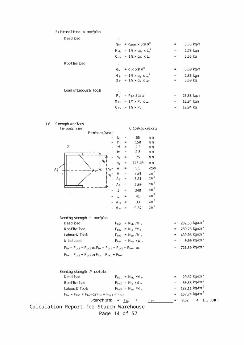
2) Internal force // roof plan
Dead load :
qdy = qdtotal x Sin αo = 5.55 kg/m
Mdy = 1/8 x qdy x lsr2 = 2.78 kgm
Qdy = 1/2 x qdy x lsr = 5.55 kg
Roof live load :
qly = ql x Sin αo = 5.69 kg/m
Mly = 1/8 x qly x lsr2 = 2.85 kgm
Qly = 1/2 x qly x lsr = 5.69 kg
Load of Labour & Tools :Py = Pl x Sin αo = 25.88 kg/m
MPy = 1/4 x Py x lsr = 12.94 kgm
QPy = 1/2 x Py = 12.94 kg
1.6 Strength AnalysisTry purlin size
Pertinent Data:- b = 65 mm- h = 150 mm- tf = 2.3 mm- tw = 2.3 mm- h1 = 75 mm
- h2 = 145.40 mm- w = 5.5 kg/m- A = 7.01 cm2
- A1 = 3.51 cm2
- A2 = 2.80 cm2
- Ix = 248 cm4
- Iy = 41 cm4
- Wx = 33 cm3
- Wy = 9.37 cm3
Bending strength ┴ roof planDead load Fbx1 = Mdx / Wx = 282.53 kg/cm2
Roof live load Fbx2 = Mlx / Wx = 289.78 kg/cm2
Labour & Tools Fbx3 = Mpx / Wx = 439.06 kg/cm2
Wind Load Fbx4 = Mwx / Wx = 0.00 kg/cm2
Fbx = Fbx1 + Fbx2 or Fbx = Fbx1 + Fbx2 + Fbx4 or = 721.59 kg/cm2
Fbx = Fbx1 + Fbx3 or Fbx = Fbx1 + Fbx4
Bending strength // roof planDead load Fby 1 = Mdy / Wy = 29.62 kg/cm2
Roof live load Fby 2 = Mly / Wy = 30.38 kg/cm2
Labour & Tools Fby 3 = Mpy / Wy = 138.11 kg/cm2
Fby = Fby 1 + Fby 2 or Fby = Fby 1 + Fby 3 = 167.74 kg/cm2
Strength ratio = Fbx + Fby = 0.62 < 1 …. OK !Fbxall Fby all
C 150x65x20x2.3
A1 A2
y
x
h1
h2
h2
Calculation Report for Starch Warehouse Page 11 of 57
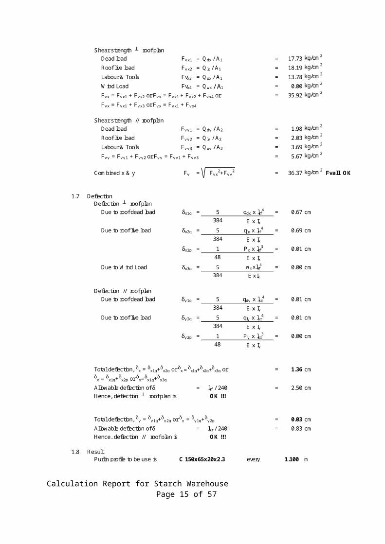
Shear strength ┴ roof planDead load Fv x1 = Qdx / A1 = 17.73 kg/cm2
Roof live load Fv x2 = Qlx / A1 = 18.19 kg/cm2
Labour & Tools Fvx3 = Qpx / A1 = 13.78 kg/cm2
Wind Load Fvx4 = Qwx / A1 = 0.00 kg/cm2
Fv x = Fv x1 + Fv x2 or Fv x = Fv x1 + Fv x2 + Fv x4 or = 35.92 kg/cm2
Fv x = Fv x1 + Fv x3 or Fv x = Fv x1 + Fv x4
Shear strength // roof planDead load Fv y 1 = Qdy / A2 = 1.98 kg/cm2
Roof live load Fv y 2 = Qly / A2 = 2.03 kg/cm2
Labour & Tools Fv y 3 = Qpy / A2 = 3.69 kg/cm2
Fv y = Fv y 1 + Fv y 2 or Fv y = Fv y 1 + Fv y 3 = 5.67 kg/cm2
Combined x & y Fv = Fv x2+Fv y
2 = 36.37 kg/cm2 Fvall OK
1.7 DeflectionDeflection ┴ roof plan
Due to roof dead load δx1q = 5 qdx x lrf 4 = 0.67 cm384 E x Ix
Due to roof live load δx2q = 5 qlx x lrf 4 = 0.69 cm384 E x Ix
δx2p = 1 Px x lrf 3 = 0.01 cm48 E x Ix
Due to Wind Load δx3q = 5 wx x lrf4 = 0.00 cm
384 E x Ix
Deflection // roof planDue to roof dead load δy 1q = 5 qdy x lsr
4 = 0.01 cm384 E x Iy
Due to roof live load δy 2q = 5 qly x lsr4 = 0.01 cm
384 E x Iyδy 2p = 1 Py x lsr
3 = 0.00 cm48 E x Iy
Total deflection, dx = dx1q+dx2q or dx = dx1q+dx2q+dx3q or = 1.36 cmdx = dx1q+dx2p or dx=dx1q+dx3q
Allowable deflection of δ = lrf / 240 = 2.50 cmHence, deflection ┴ roof plan is OK !!!
Total deflection, dy = dy 1q+dy 2q or dy = dy 1q+dy 2p = 0.03 cm
Allowable deflection of δ = lsr / 240 = 0.83 cmHence, deflection // roof plan is OK !!!
1.8 ResultPurlin profile to be use is C 150x65x20x2.3 every 1.100 m
Calculation Report for Starch Warehouse Page 12 of 57
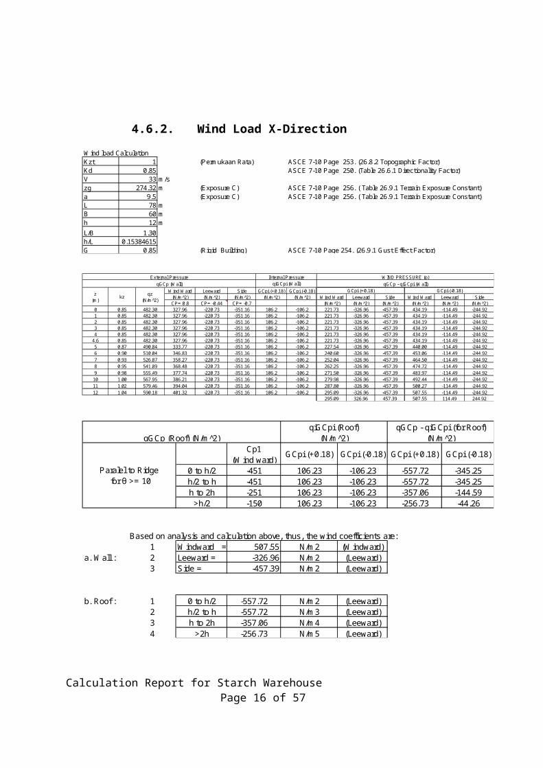
4.6.2. Wind Load X-DirectionWind load CalculationKzt 1 (Permukaan Rata) ASCE 7-10 Page 253. (26.8.2 Topographic Factor)Kd 0.85 ASCE 7-10 Page 250. (Table 26.6.1 Directionality Factor)V 33 m/szg 274.32 m (Exposure C) ASCE 7-10 Page 256. ( Table 26.9.1 Terrain Exposure Constant)a 9.5 (Exposure C) ASCE 7-10 Page 256. ( Table 26.9.1 Terrain Exposure Constant)L 78 mB 60 mh 12 mL/B 1.30h/L 0.15384615G 0.85 (Rigid Building) ASCE 7-10 Page 254. (26.9.1 Gust Effect Factor)
Wind Ward Leeward Side GCpi (+0.18) GCpi (-0.18)(N/m 2̂) (N/m 2̂) (N/m 2̂) (N/m 2̂) (N/m 2̂) Wind Ward Leeward Side Wind Ward Leeward SideCP= 0.8 CP= -0.44 CP= -0.7 (N/m 2̂) (N/m 2̂) (N/m 2̂) (N/m 2̂) (N/m 2̂) (N/m 2̂)
0 0.85 482.30 327.96 -220.73 -351.16 106.2 -106.2 221.73 -326.96 -457.39 434.19 -114.49 -244.921 0.85 482.30 327.96 -220.73 -351.16 106.2 -106.2 221.73 -326.96 -457.39 434.19 -114.49 -244.922 0.85 482.30 327.96 -220.73 -351.16 106.2 -106.2 221.73 -326.96 -457.39 434.19 -114.49 -244.923 0.85 482.30 327.96 -220.73 -351.16 106.2 -106.2 221.73 -326.96 -457.39 434.19 -114.49 -244.924 0.85 482.30 327.96 -220.73 -351.16 106.2 -106.2 221.73 -326.96 -457.39 434.19 -114.49 -244.92
4.6 0.85 482.30 327.96 -220.73 -351.16 106.2 -106.2 221.73 -326.96 -457.39 434.19 -114.49 -244.925 0.87 490.84 333.77 -220.73 -351.16 106.2 -106.2 227.54 -326.96 -457.39 440.00 -114.49 -244.926 0.90 510.04 346.83 -220.73 -351.16 106.2 -106.2 240.60 -326.96 -457.39 453.06 -114.49 -244.927 0.93 526.87 358.27 -220.73 -351.16 106.2 -106.2 252.04 -326.96 -457.39 464.50 -114.49 -244.928 0.95 541.89 368.48 -220.73 -351.16 106.2 -106.2 262.25 -326.96 -457.39 474.72 -114.49 -244.929 0.98 555.49 377.74 -220.73 -351.16 106.2 -106.2 271.50 -326.96 -457.39 483.97 -114.49 -244.92
10 1.00 567.95 386.21 -220.73 -351.16 106.2 -106.2 279.98 -326.96 -457.39 492.44 -114.49 -244.9211 1.02 579.46 394.04 -220.73 -351.16 106.2 -106.2 287.80 -326.96 -457.39 500.27 -114.49 -244.9212 1.04 590.18 401.32 -220.73 -351.16 106.2 -106.2 295.09 -326.96 -457.39 507.55 -114.49 -244.92
295.09 326.96 457.39 507.55 114.49 244.92
WIND PRESSURE (p)qGCp (Wall) qiGCpi (Wall) qGCp - qiGCpi (Wall)
External Pressure Internal Pressure
z (m)
kz qz (N/m 2̂)
GCpi (+0.18) GCpi (-0.18)
0 to h/2 -451 106.23 -106.23 -557.72 -345.25h/2 to h -451 106.23 -106.23 -557.72 -345.25h to 2h -251 106.23 -106.23 -357.06 -144.59>h/2 -150 106.23 -106.23 -256.73 -44.26
Based on analysis and calculation above, thus, the wind coefficients are:1 Windward = 507.55 N/m2 (Windward)
a. Wall : 2 Leeward = -326.96 N/m2 (Leeward)3 Side = -457.39 N/m2 (Leeward)
b. Roof : 1 0 to h/2 -557.72 N/m2 (Leeward)2 h/2 to h -557.72 N/m3 (Leeward)3 h to 2h -357.06 N/m4 (Leeward)4 >2h -256.73 N/m5 (Leeward)
qGCp (Roof) (N/m 2̂)qiGCpi (Roof)
(N/m 2̂)qGCp - qiGCpi (for Roof)
(N/m 2̂)
Paralel to Ridge for θ >= 10
Cp1 (Wind ward)
GCpi (+0.18) GCpi (-0.18) GCpi (+0.18) GCpi (-0.18)
Calculation Report for Starch Warehouse Page 13 of 57
4.6.3. Wind Y-DirectionWind load CalculationKzt 1 (Permukaan Rata) ASCE 7-10 Page 253. (26.8.2 Topographic Factor)Kd 0.85 ASCE 7-10 Page 250. (Table 26.6.1 Directionality Factor)V 33 m/szg 274.32 m (Exposure C) ASCE 7-10 Page 256. ( Table 26.9.1 Terrain Exposure Constant)a 9.5 (Exposure C) ASCE 7-10 Page 256. ( Table 26.9.1 Terrain Exposure Constant)L 60 mB 78 mh 12 mL/B 0.77h/L 0.200G 0.85 (Rigid Building) ASCE 7-10 Page 254. (26.9.1 Gust Effect Factor)
Wind Ward Leeward Side GCpi (+0.18) GCpi (-0.18)(N/m^2) (N/m^2) (N/m^2) (N/m^2) (N/m^2) Wind Ward Leeward Side Wind Ward Leeward SideCP= 0.8 CP= -0.5 CP= -0.7 (N/m 2̂) (N/m 2̂) (N/m 2̂) (N/m 2̂) (N/m^2) (N/m 2̂)
0 0.85 482.30 327.96 -250.83 -351.16 106.2 -106.2 221.73 -357.06 -457.39 434.19 -144.59 -244.921 0.85 482.30 327.96 -250.83 -351.16 106.2 -106.2 221.73 -357.06 -457.39 434.19 -144.59 -244.922 0.85 482.30 327.96 -250.83 -351.16 106.2 -106.2 221.73 -357.06 -457.39 434.19 -144.59 -244.923 0.85 482.30 327.96 -250.83 -351.16 106.2 -106.2 221.73 -357.06 -457.39 434.19 -144.59 -244.924 0.85 482.30 327.96 -250.83 -351.16 106.2 -106.2 221.73 -357.06 -457.39 434.19 -144.59 -244.92
4.6 0.85 482.30 327.96 -250.83 -351.16 106.2 -106.2 221.73 -357.06 -457.39 434.19 -144.59 -244.925 0.87 490.84 333.77 -250.83 -351.16 106.2 -106.2 227.54 -357.06 -457.39 440.00 -144.59 -244.926 0.90 510.04 346.83 -250.83 -351.16 106.2 -106.2 240.60 -357.06 -457.39 453.06 -144.59 -244.927 0.93 526.87 358.27 -250.83 -351.16 106.2 -106.2 252.04 -357.06 -457.39 464.50 -144.59 -244.928 0.95 541.89 368.48 -250.83 -351.16 106.2 -106.2 262.25 -357.06 -457.39 474.72 -144.59 -244.929 0.98 555.49 377.74 -250.83 -351.16 106.2 -106.2 271.50 -357.06 -457.39 483.97 -144.59 -244.92
10 1.00 567.95 386.21 -250.83 -351.16 106.2 -106.2 279.98 -357.06 -457.39 492.44 -144.59 -244.9211 1.02 579.46 394.04 -250.83 -351.16 106.2 -106.2 287.80 -357.06 -457.39 500.27 -144.59 -244.9212 1.04 590.18 401.32 -250.83 -351.16 106.2 -106.2 295.09 -357.06 -457.39 507.55 -144.59 -244.92
295.09 357.06 457.39 507.55 144.59 244.92
External Pressure Internal Pressure WIND PRESSURE (p)qGCp (Wall) qiGCpi (Wall) qGCp - qiGCpi (Wall)
z (m)
kz qz (N/m 2̂)
GCpi (+0.18) GCpi (-0.18)
-351 -251 106.23 -106.23 -457.39 -357.06 -244.92 -144.59-90 -251 106.23 -106.23 -196.53 -357.06 15.93 -144.59
Based on analysis and calculation above, thus, the wind coefficients are:1 Windward = 507.55 N/m2 (Windward)
a. Wall : 2 Leeward = -357.06 N/m2 (Leeward)3 Side = -457.39 N/m2 (Leeward)
a. Roof : 1 Windward = -457.39 N/m2 (Leeward)2 Leeward = -357.06 N/m2 (Leeward)
qGCp (Roof) (N/m 2̂) qiGCpi (Roof) (N/m^2) qGCp - qiGCpi (for Roof) (N/m^2)
Normal to Ridge for θ >= 10
Cp1(Wind ward)
Cp2 (Leeward)
GCpi (+0.18) GCpi (-0.18)GCpi (-0.18)
Cp1(Wind ward)
Cp2 (Leeward)
Cp1(Wind ward)
Cp2 (Leeward)
GCpi (+0.18)
Calculation Report for Starch Warehouse Page 14 of 57
5. LOADS AND LOADS COMBINATIONSThe design loads for Building structure and foundation shall be specified in the functional design requirement and necessary loads required by ASCE 7-02
5.1. Dead Load (DL)The actual weights of material shall be used for the purpose of the structural design.a. Steel frame = 7850 kg/m3
b. Concrete = 2450 kg/m2
5.2. Live Load (LL)a. Live Load = 5000 kg/m2.
b. Roof Live Load = 20 kg/m2
5.3. Seismic Load (EL)The structures shall be designed to resist all lateral load imposed by the seismic in
accordance to SNI 1726-2012. This Code considers 100% earthquake action in one
direction, in combination with 30 % earthquake action in its perpendicular direction.
Vx = EQX + 0.3EQY
Vy = EQY + 0.3 EQX
Where:
Vx : Seismic Load in X direction
Vy : Seismic Load in Y direction
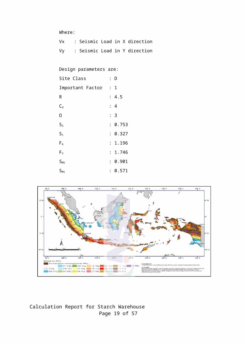
Design parameters are:
Site Class : D
Important Factor : 1
R : 4.5
Cd : 4
Ω : 3
SS : 0.753
S1 : 0.327
FA : 1.196
FV : 1.746
Calculation Report for Starch Warehouse Page 15 of 57
SMS : 0.901
SM1 : 0.571
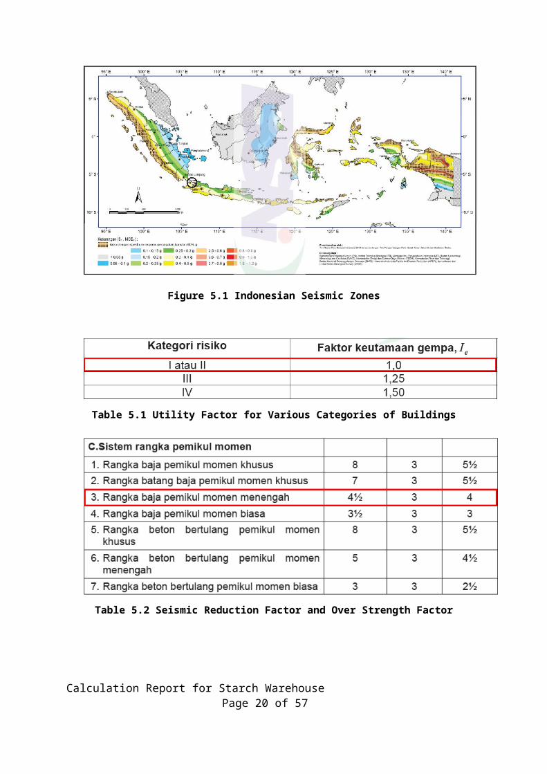
Figure 5.1 Indonesian Seismic Zones
Table 5.1 Utility Factor for Various Categories of Buildings
Calculation Report for Starch Warehouse Page 16 of 57
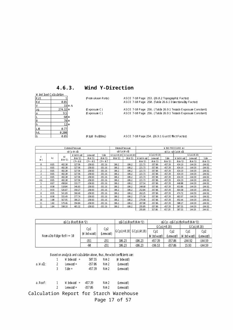
Table 5.2 Seismic Reduction Factor and Over Strength Factor
Figure 5.2 Specific Response Spectrum for this site
Seismic Load Calculation is accommodating by SAP 2000 Program. The parameter of seismic load shall be input to the program is of Reduction Factor (R), Important factor (I), Vertical seismic response factor (SDS and SD1). Total weight of structure is compute by program.
Calculation Report for Starch Warehouse Page 17 of 57
Figure 5.3 Seismic Load
5.4. Combination of Load
The load combination for the steel structure analysis and design (general) is below:
(DL + SDL) (DL + SDL) + 1.0 LL (DL + SDL) + (1.0 Lr or 1.0 R) (DL + SDL) + 0.75 LL + (0.75 Lr or 0.75 R) 1.082** (DL + SDL) ± 0.7 Ex ± 0.21 Ey 1.082** (DL + SDL) ± 0.7 Ey ± 0.21 Ex 1.058*** (DL + SDL) ± 0.75 (0.7 Ex) ± 0.75 (0.21 Ey) + 0.75 LL + (0.75 Lr or 0.75 R) 1.058*** (DL + SDL) ± 0.75 (0.7 Ey) ± 0.75 (0.21 Ex) + 0.75 LL + (0.75 Lr or 0.75 R) (DL + SDL) ± 0.6 WL (DL + SDL) ± 0.75 (0.6 WL) + 0.75 LL + (0.75 Lr or 0.75 R) 0.6 (DL + SDL) ± 0.6 WL (DL + SDL) ± 0.6 (0.75 Wx) ± 0.6 (0.75 Wy) (DL + SDL) ± 0.75 (0.75 Wx) ± 0.75 (0.75 Wy) 0.517**** (DL + SDL) ± 0.7 Ex ± 0.21 Ey 0.517**** (DL + SDL) ± 0.7 Ey ± 0.21 Ex
Note: ** coefficient vertical impact earthquake = Coeff. DL + 0.14 SDs= 1 +0.14(0.6018) = 1.084252
*** coefficient vertical impact earthquake = Coeff. DL + 0.1 SDs= 1 + 0.1(0.6018) = 1.06018
**** coefficient vertical impact earthquake = Coeff. DL - 0.14 SDsCalculation Report for Starch Warehouse Page 18 of 57
= 0.6 - 0.14(0.6018) = 0.51575The load combination for the concrete structure analysis and design is below :
1.4 (DL + SDL) 1.2 (DL + SDL) + 1.6 LL 1.317* (DL + SDL) + 0.5 LL ± 1.0 Ex ± 0.3 Ey 1.317* (DL + SDL) + 0.5 LL ± 0.3 Ex ± 1 Ey 0.828** (DL + SDL) ± 1.0 Ex ± 0.3 Ey 0.828** (DL + SDL) ± 0.3 Ey ± 1 Ex
Note: * coefficient vertical impact earthquake = Coeff. DL + 0.2 SDs= 1.2 + 0.2(0.6018) = 1.320
** coefficient vertical impact earthquake = Coeff. DL - 0.2 SDs = 0.9 - 0.2(0.6018)= 0.779 The load combination for foundation design: (DL + SDL) + 1.0 LL ± 1.0 Ex ± 0.3 Ey (DL + SDL) + 1.0 LL ± 0.3 Ex ± 1.0 Ey (DL + SDL) + 1.0 LL
Where: DL : Dead Load SDL : Superimposed Dead Load LL : Live Load Wx : Wind Load X – direction Wy : Wind Load Y – direction EL : Earth quake Load Ex : Earth quake Load X – direction Ey : Earth quake Load Y – direction
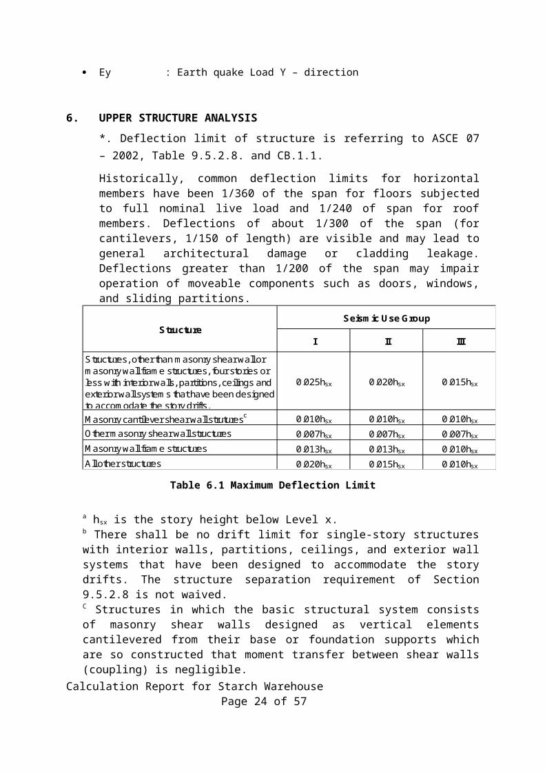
6. UPPER STRUCTURE ANALYSIS*. Deflection limit of structure is referring to ASCE 07 – 2002, Table 9.5.2.8. and CB.1.1.
Historically, common deflection limits for horizontal members have been 1/360 of the span for floors subjected to full nominal live load and 1/240 of span for roof members. Deflections of about 1/300 of the span (for cantilevers, 1/150 of length) are visible and may lead to general architectural damage or cladding leakage. Deflections greater than 1/200 of the span may impair operation of moveable components such as doors, windows, and sliding partitions.
Calculation Report for Starch Warehouse Page 19 of 57
0.010hsx
0.020hsx 0.015hsx 0.010hsx
Other masonry shear wall structures
Masonry wall frame structures
All other structures
0.010hsx 0.010hsx
0.007hsx 0.007hsx 0.007hsx
0.013hsx 0.013hsx
Structures, other than masonry shear wall or masonry wall frame structures, four stories or less with interior walls, partitions, ceilings and exterior wall systems that have been designed to accomodate the story drifts.
0.025hsx 0.020hsx 0.015hsx
0.010hsxMasonry cantilever shear wall struturesc
StructureSeismic Use Group
I II III
Table 6.1 Maximum Deflection Limit
a hsx is the story height below Level x.b There shall be no drift limit for single-story structures with interior walls, partitions, ceilings, and exterior wall systems that have been designed to accommodate the story drifts. The structure separation requirement of Section 9.5.2.8 is not waived. C Structures in which the basic structural system consists of masonry shear walls designed as vertical elements cantilevered from their base or foundation supports which are so constructed that moment transfer between shear walls (coupling) is negligible.
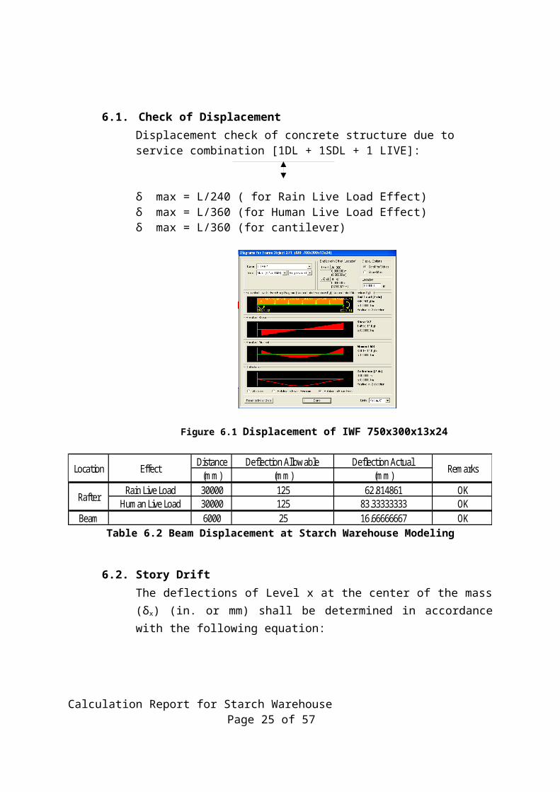
6.1. Check of DisplacementDisplacement check of concrete structure due to service combination [1DL + 1SDL + 1 LIVE]:
δ max = L/240 ( for Rain Live Load Effect)δ max = L/360 (for Human Live Load Effect)δ max = L/360 (for cantilever)
Calculation Report for Starch Warehouse Page 20 of 57
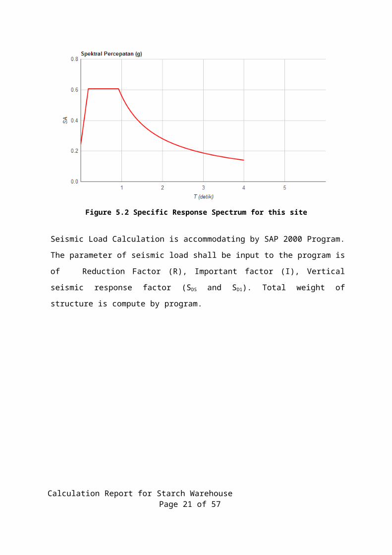
Figure 6.1 Displacement of IWF 750x300x13x24
Distance Deflection Allowable Deflection Actual (mm) (mm) (mm)
Rain Live Load 30000 125 62.814861 OKHuman Live Load 30000 125 83.33333333 OK
Beam 6000 25 16.66666667 OK
EffectLocation Remarks
Rafter
Table 6.2 Beam Displacement at Starch Warehouse Modeling
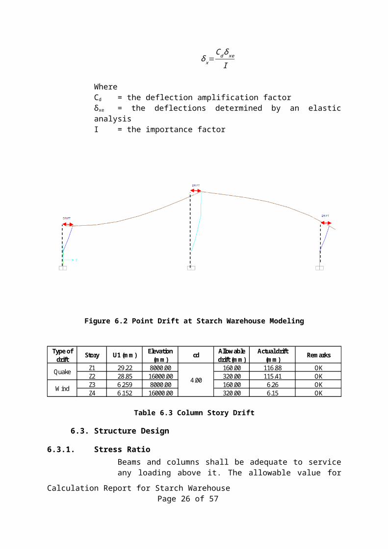
6.2. Story DriftThe deflections of Level x at the center of the mass (δx) (in. or mm) shall be determined in accordance with the following equation:
δ x=Cd δ xe
I
Where Cd = the deflection amplification factorδxe = the deflections determined by an elastic analysis I = the importance factor
Calculation Report for Starch Warehouse Page 21 of 57
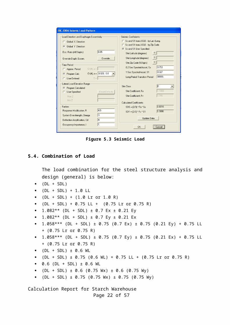
Figure 6.2 Point Drift at Starch Warehouse Modeling
Z1 29.22 8000.00 160.00 116.88 OKZ2 28.85 16000.00 320.00 115.41 OKZ3 6.259 8000.00 160.00 6.26 OKZ4 6.152 16000.00 320.00 6.15 OK
4.00Quake
Wind
Type of drift
Actual drift (mm)
RemarksStory U1 (mm) Elevation (mm)
cd Allowable drift (mm)
Table 6.3 Column Story Drift
6.3. Structure Design
6.3.1. Stress RatioBeams and columns shall be adequate to service any loading above it. The allowable value for the stress ratio indicating that the beams and columns are adequate to accommodate the loadings is below 1.0 (SR < 1.0).
Calculation Report for Starch Warehouse Page 22 of 57
Based on the results, we can summaries as follows: All steel structures members are sufficient to receive the designed loads. Vertical deflection of the column meets the service condition
requirement.
Calculation Report for Starch Warehouse Page 23 of 57
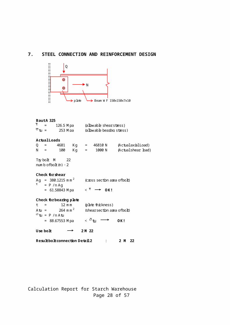
7. STEEL CONNECTION AND REINFORCEMENT DESIGN
Baut A 325t = 126.5 Mpa (allowable shear stress)s tu = 253 Mpa (allowable bearing stress)
Actual Loads Q = 4681 Kg = 46810 N (Actual axial Load)N = 100 Kg = 1000 N (Actual shear load)
Try bolt M 22numb of bolt (n) =2
Check for shearAg = 380.1215 mm2 (cross section area of bolt)t = P / n Ag
= 61.58843 Mpa < t OK! 1
Check for bearing platet = 12 mm (plate thickness)Atu = 264 mm2 (shear section area of bolt)s tu = P / n Atu
= 88.67553 Mpa < s tu OK! 12
Use bolt 2 M 22
Result bolt connection Detail 2 : 2 M 22
N
Q
plate Beam WF 150x150x7x10
Calculation Report for Starch Warehouse Page 24 of 57
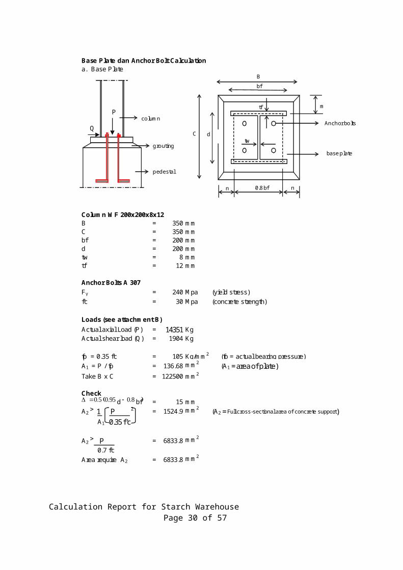
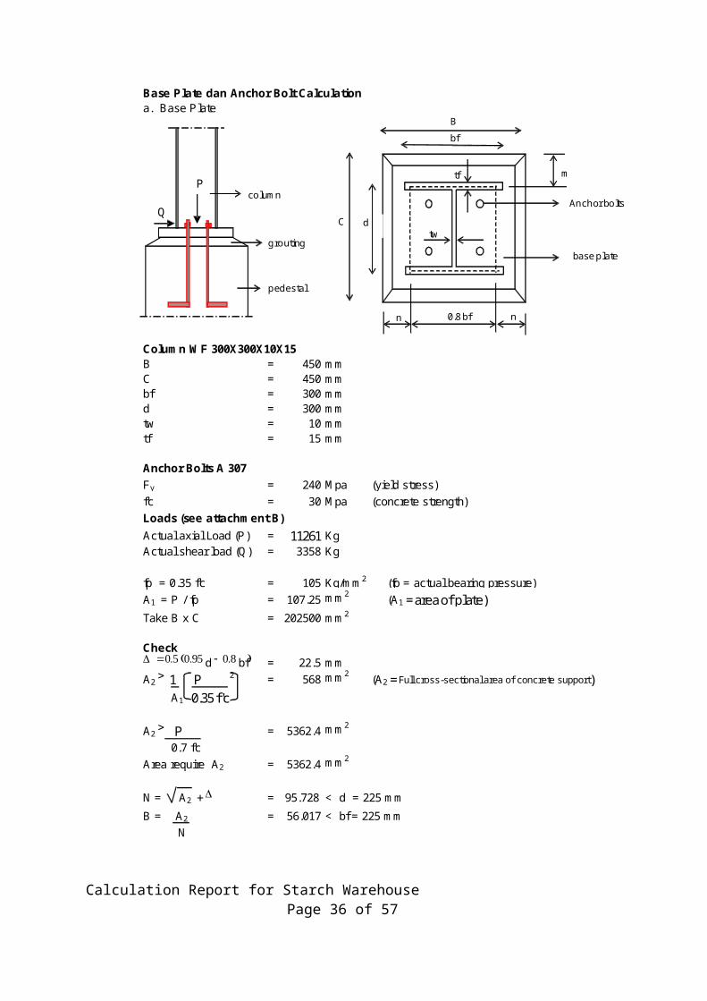
Base Plate dan Anchor Bolt Calculationa. Base Plate
Column WF 200x200x8x12B = 350 mmC = 350 mmbf = 200 mmd = 200 mmtw = 8 mmtf = 12 mm
Anchor Bolts A 307Fy = 240 Mpa (yield stress)f'c = 30 Mpa (concrete strength)
Loads (see attachment B)Actual axial Load (P) = 14351 KgActual shear load (Q) = 1904 Kg
fp = 0.35 f'c = 105 Kg/mm2 (fp = actual bearing pressure)A1 = P / fp = 136.68 mm2 (A1 = area of plate)Take B x C = 122500 mm2
CheckD = 0.5 (0.95 d - 0.8 bf) = 15 mmA2 > 1 P 2 = 1524.9 mm2 (A2 = Full cross-sectional area of concrete support) A1 0.35 f'c
A2 > P = 6833.8 mm2
0.7 f'cArea require A2 = 6833.8 mm2
Q
grouting
column
pedestal
P
C
0.8 bf
base plate
Anchor bolts
nn
B
bf
d
tf
tw
m
Calculation Report for Starch Warehouse Page 25 of 57
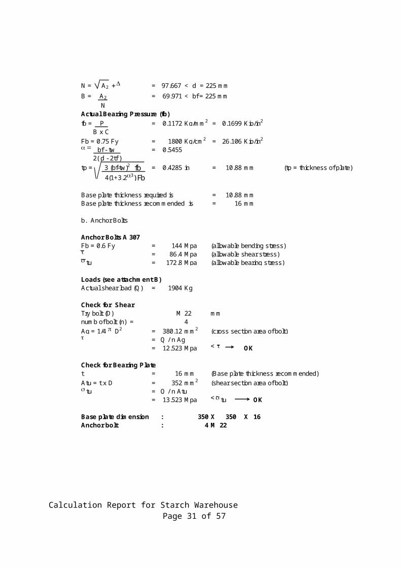
N = A2 + D = 97.667 < d = 225 mm
B = A2 = 69.971 < bf = 225 mm N Actual Bearing Pressure (fb)fb = P = 0.1172 Kg/mm2 = 0.1699 Kip/in2
B x CFb = 0.75 Fy = 1800 Kg/cm2 = 26.106 Kip/in2
a = bf - tw = 0.5455 2( d - 2tf )tp = 3 (bf-tw)2 fb = 0.4285 in = 10.88 mm (tp = thickness of plate) 4(1+3.2a3) Fb
Base plate thickness required is = 10.88 mmBase plate thickness recommended is = 16 mm
b. Anchor Bolts
Anchor Bolts A 307Fb = 0.6 Fy = 144 Mpa (allowable bending stress)t = 86.4 Mpa (allowable shear stress)s tu = 172.8 Mpa (allowable bearing stress)
Loads (see attachment B)Actual shear load (Q) = 1904 Kg
Check for ShearTry bolt (D) M 22 mmnumb of bolt (n) = 4Ag = 1/4 p D2 = 380.12 mm2 (cross section area of bolt)t = Q / n Ag
= 12.523 Mpa < t OK 0
Check for Bearing Platet = 16 mm (Base plate thickness recommended)Atu = t x D = 352 mm2 (shear section area of bolt)s tu = Q / n Atu
= 13.523 Mpa < s tu OK 0
Base plate dimension : 350 X 350 X 16Anchor bolt : 4 M 22
Calculation Report for Starch Warehouse Page 26 of 57

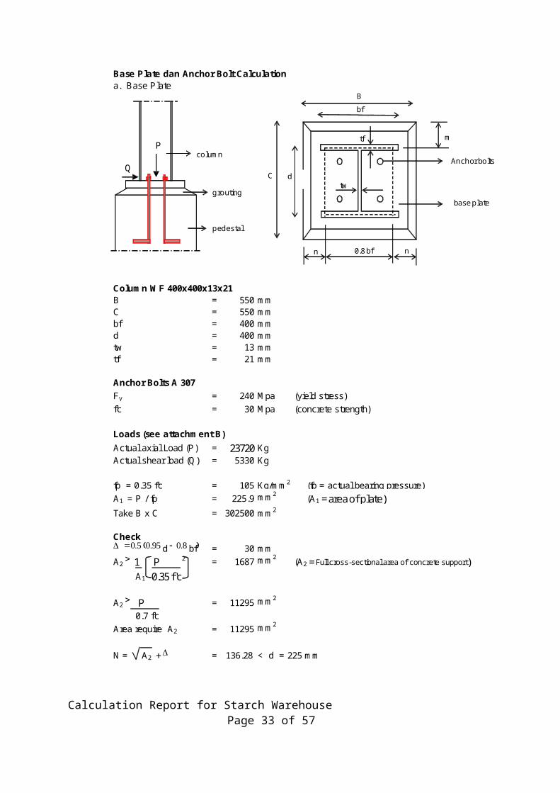
Base Plate dan Anchor Bolt Calculationa. Base Plate
Column WF 400x400x13x21B = 550 mmC = 550 mmbf = 400 mmd = 400 mmtw = 13 mmtf = 21 mm
Anchor Bolts A 307Fy = 240 Mpa (yield stress)f'c = 30 Mpa (concrete strength)
Loads (see attachment B)Actual axial Load (P) = 23720 KgActual shear load (Q) = 5330 Kg
fp = 0.35 f'c = 105 Kg/mm2 (fp = actual bearing pressure)A1 = P / fp = 225.9 mm2 (A1 = area of plate)Take B x C = 302500 mm2
CheckD = 0.5 (0.95 d - 0.8 bf) = 30 mmA2 > 1 P 2 = 1687 mm2 (A2 = Full cross-sectional area of concrete support) A1 0.35 f'c
A2 > P = 11295 mm2
0.7 f'cArea require A2 = 11295 mm2
N = A2 + D = 136.28 < d = 225 mm
Q
grouting
column
pedestal
P
C
0.8 bf
base plate
Anchor bolts
nn
B
bf
d
tf
tw
m
Calculation Report for Starch Warehouse Page 27 of 57
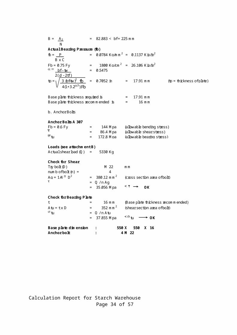
B = A2 = 82.883 < bf = 225 mm N Actual Bearing Pressure (fb)fb = P = 0.0784 Kg/mm2 = 0.1137 Kip/in2
B x CFb = 0.75 Fy = 1800 Kg/cm2 = 26.106 Kip/in2
a = bf - tw = 0.5475 2( d - 2tf )tp = 3 (bf-tw)2 fb = 0.7052 in = 17.91 mm (tp = thickness of plate) 4(1+3.2a3) Fb
Base plate thickness required is = 17.91 mmBase plate thickness recommended is = 16 mm
b. Anchor Bolts
Anchor Bolts A 307Fb = 0.6 Fy = 144 Mpa (allowable bending stress)t = 86.4 Mpa (allowable shear stress)s tu = 172.8 Mpa (allowable bearing stress)
Loads (see attachment B)Actual shear load (Q) = 5330 Kg
Check for ShearTry bolt (D) M 22 mmnumb of bolt (n) = 4Ag = 1/4 p D2 = 380.12 mm2 (cross section area of bolt)t = Q / n Ag
= 35.056 Mpa < t OK 0
Check for Bearing Platet = 16 mm (Base plate thickness recommended)Atu = t x D = 352 mm2 (shear section area of bolt)s tu = Q / n Atu
= 37.855 Mpa < s tu OK 0
Base plate dimension : 550 X 550 X 16Anchor bolt : 4 M 22
Calculation Report for Starch Warehouse Page 28 of 57

Base Plate dan Anchor Bolt Calculationa. Base Plate
Column WF 300X300X10X15B = 450 mmC = 450 mmbf = 300 mmd = 300 mmtw = 10 mmtf = 15 mm
Anchor Bolts A 307Fy = 240 Mpa (yield stress)f'c = 30 Mpa (concrete strength)Loads (see attachment B)Actual axial Load (P) = 11261 KgActual shear load (Q) = 3358 Kg
fp = 0.35 f'c = 105 Kg/mm2 (fp = actual bearing pressure)A1 = P / fp = 107.25 mm2 (A1 = area of plate)Take B x C = 202500 mm2
CheckD = 0.5 (0.95 d - 0.8 bf) = 22.5 mmA2 > 1 P 2 = 568 mm2 (A2 = Full cross-sectional area of concrete support) A1 0.35 f'c
A2 > P = 5362.4 mm2
0.7 f'cArea require A2 = 5362.4 mm2
N = A2 + D = 95.728 < d = 225 mm
B = A2 = 56.017 < bf = 225 mm N
Q
grouting
column
pedestal
P
C
0.8 bf
base plate
Anchor bolts
nn
B
bf
d
tf
tw
m
Calculation Report for Starch Warehouse Page 29 of 57
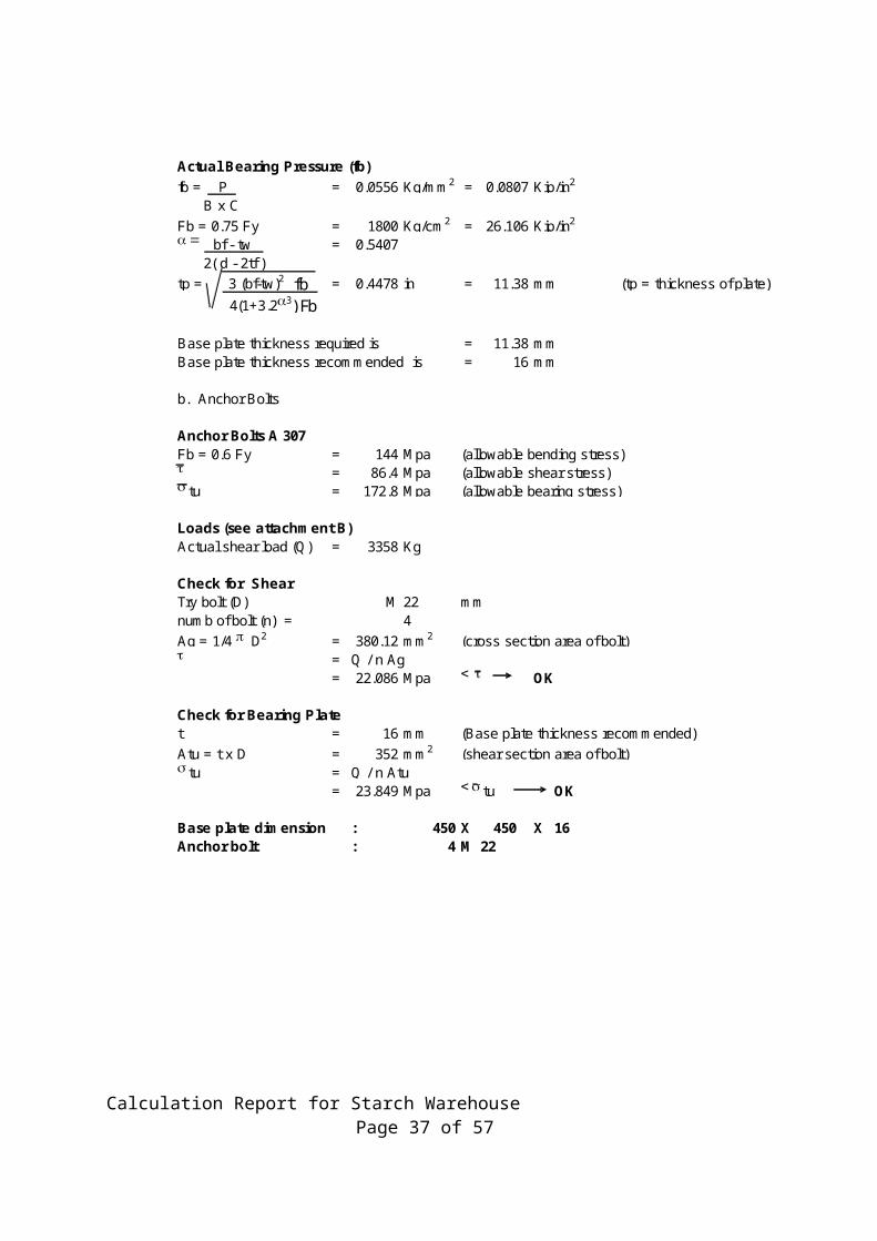
Actual Bearing Pressure (fb)fb = P = 0.0556 Kg/mm2 = 0.0807 Kip/in2
B x CFb = 0.75 Fy = 1800 Kg/cm2 = 26.106 Kip/in2
a = bf - tw = 0.5407 2( d - 2tf )tp = 3 (bf-tw)2 fb = 0.4478 in = 11.38 mm (tp = thickness of plate) 4(1+3.2a3) Fb
Base plate thickness required is = 11.38 mmBase plate thickness recommended is = 16 mm
b. Anchor Bolts
Anchor Bolts A 307Fb = 0.6 Fy = 144 Mpa (allowable bending stress)t = 86.4 Mpa (allowable shear stress)s tu = 172.8 Mpa (allowable bearing stress)
Loads (see attachment B)Actual shear load (Q) = 3358 Kg
Check for ShearTry bolt (D) M 22 mmnumb of bolt (n) = 4Ag = 1/4 p D2 = 380.12 mm2 (cross section area of bolt)t = Q / n Ag
= 22.086 Mpa < t OK 0
Check for Bearing Platet = 16 mm (Base plate thickness recommended)Atu = t x D = 352 mm2 (shear section area of bolt)s tu = Q / n Atu
= 23.849 Mpa < s tu OK 0
Base plate dimension : 450 X 450 X 16Anchor bolt : 4 M 22
Calculation Report for Starch Warehouse Page 30 of 57
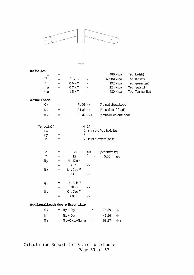
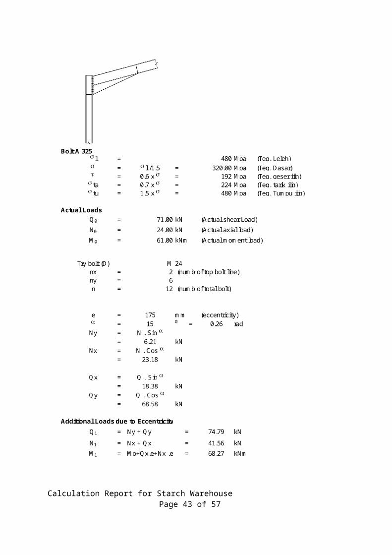
Bolt A 325s l = 480 Mpa (Teg. Leleh)s = s l /1.5 = 320.00 Mpa (Teg. Dasar)t = 0.6 x s = 192 Mpa (Teg. geser ijin)s ta = 0.7 x s = 224 Mpa (Teg. tarik ijin)s tu = 1.5 x s = 480 Mpa (Teg. Tumpu ijin)
Actual LoadsQ0 = 71.00 kN (Actual shear Load)
N0 = 24.00 kN (Actual axial load)M0 = 61.00 kNm (Actual moment load)
Try bolt (D) M 24nx = 2 (numb of top bolt line)ny = 6n = 12 (numb of total bolt)
e = 175 mm (eccentricity)a = 15 0 = 0.26 rad
Ny = N . Sin a= 6.21 kN
Nx = N . Cos a= 23.18 kN
Qx = Q . Sin a= 18.38 kN
Qy = Q . Cos a= 68.58 kN
Additional Loads due to EccentricityQ1 = Ny + Qy = 74.79 kN
N1 = Nx + Qx = 41.56 kN
M1 = Mo+Qx.e+Nx .e = 68.27 kNm
Calculation Report for Starch Warehouse Page 31 of 57

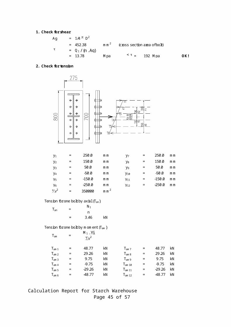
1. Check for shearAg = 1/4 p D2
= 452.38 mm2 (cross section area of bolt)t = Q1 / (n . Ag)
= 13.78 Mpa < t = 192 Mpa OK!
2. Check for tension
y1 = 250.0 mm y7 = 250.0 mm
y2 = 150.0 mm y8 = 150.0 mmy3 = 50.0 mm y9 = 50.0 mmy4 = -50.0 mm y10 = -50.0 mmy5 = -150.0 mm y11 = -150.0 mmy6 = -250.0 mm y12 = -250.0 mm
∑y2 = 350000 mm2
Tension for one bolt by axial (Tan) N1
n = 3.46 kN
Tension for one bolt by moment (Tam)M1 . Yi
∑y2
Tam1 = 48.77 kN Tam7 = 48.77 kNTam2 = 29.26 kN Tam8 = 29.26 kNTam3 = 9.75 kN Tam9 = 9.75 kNTam4 = -9.75 kN Tam10 = -9.75 kNTam5 = -29.26 kN Tam11 = -29.26 kNTam6 = -48.77 kN Tam12 = -48.77 kN
Tan =
Tam =
Calculation Report for Starch Warehouse Page 32 of 57
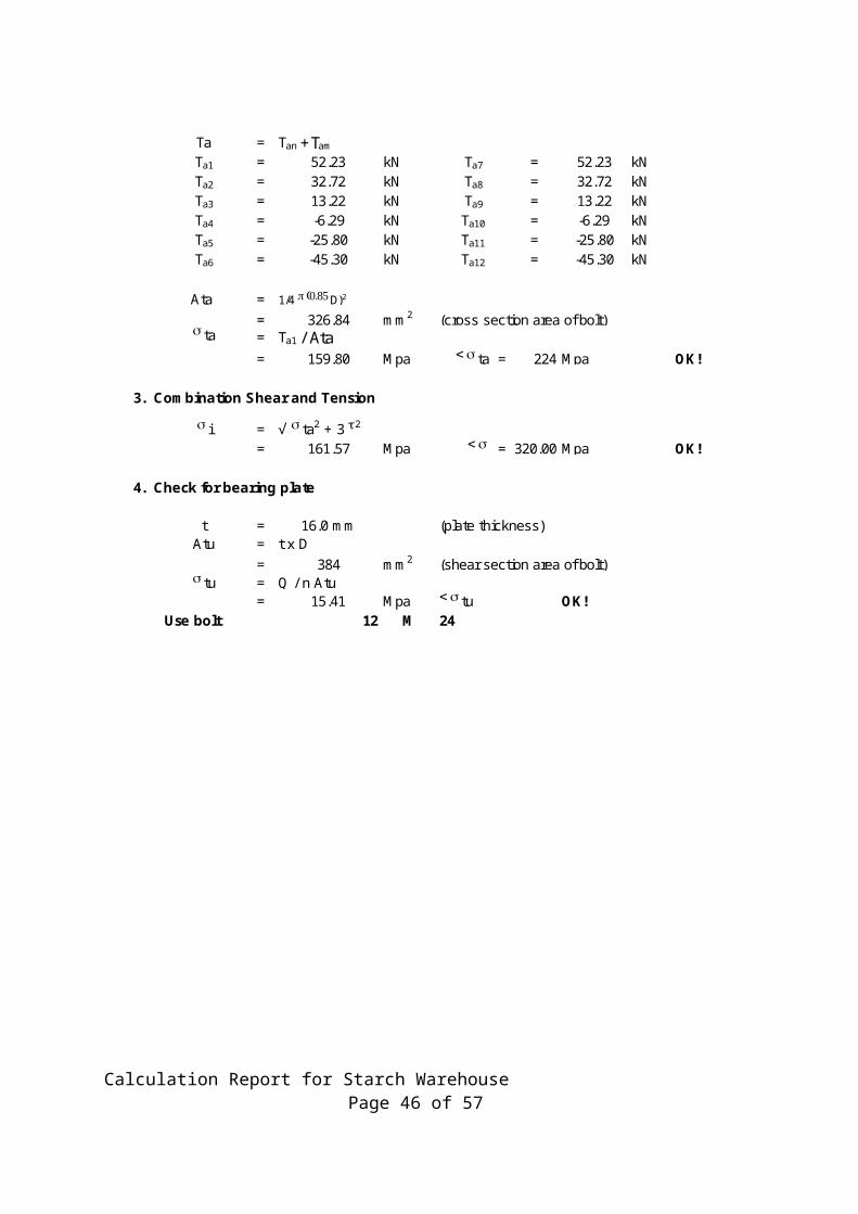
Ta = Tan + Tam
Ta1 = 52.23 kN Ta7 = 52.23 kNTa2 = 32.72 kN Ta8 = 32.72 kNTa3 = 13.22 kN Ta9 = 13.22 kNTa4 = -6.29 kN Ta10 = -6.29 kNTa5 = -25.80 kN Ta11 = -25.80 kNTa6 = -45.30 kN Ta12 = -45.30 kN
Ata = 1/4 p (0.85 D)2
= 326.84 mm2 (cross section area of bolt)s ta = Ta1 / Ata
= 159.80 Mpa < s ta = 224 Mpa OK!
3. Combination Shear and Tension
s i = √ s ta2 + 3 t2
= 161.57 Mpa < s = 320.00 Mpa OK!
4. Check for bearing plate
t = 16.0 mm (plate thickness)Atu = t x D
= 384 mm2 (shear section area of bolt)s tu = Q / n Atu
= 15.41 Mpa < s tu OK!Use bolt 12 M 24
Calculation Report for Starch Warehouse Page 33 of 57
Bolt A 325s l = 480 Mpa (Teg. Leleh)s = s l /1.5 = 320.00 Mpa (Teg. Dasar)t = 0.6 x s = 192 Mpa (Teg. geser ijin)s ta = 0.7 x s = 224 Mpa (Teg. tarik ijin)s tu = 1.5 x s = 480 Mpa (Teg. Tumpu ijin)
Actual LoadsQ0 = 71.00 kN (Actual shear Load)N0 = 24.00 kN (Actual axial load)
M0 = 61.00 kNm (Actual moment load)
Try bolt (D) M 24nx = 2 (numb of top bolt line)ny = 6n = 12 (numb of total bolt)
e = 175 mm (eccentricity)a = 15 0 = 0.26 rad
Ny = N . Sin a= 6.21 kN
Nx = N . Cos a= 23.18 kN
Qx = Q . Sin a= 18.38 kN
Qy = Q . Cos a= 68.58 kN
Additional Loads due to EccentricityQ1 = Ny + Qy = 74.79 kN
N1 = Nx + Qx = 41.56 kNM1 = Mo+Qx.e+Nx .e = 68.27 kNm
Calculation Report for Starch Warehouse Page 34 of 57

1. Check for shearAg = 1/4 p D2
= 452.38 mm2 (cross section area of bolt)t = Q1 / (n . Ag)
= 13.78 Mpa < t = 192 Mpa OK!
2. Check for tension
y1 = 250.0 mm y7 = 250.0 mmy2 = 150.0 mm y8 = 150.0 mmy3 = 50.0 mm y9 = 50.0 mmy4 = -50.0 mm y10 = -50.0 mmy5 = -150.0 mm y11 = -150.0 mmy6 = -250.0 mm y12 = -250.0 mm
∑y2 = 350000 mm2
Tension for one bolt by axial (Tan) N1
n = 3.46 kN
Tension for one bolt by moment (Tam)M1 . Yi
∑y2
Tam1 = 48.77 kN Tam7 = 48.77 kNTam2 = 29.26 kN Tam8 = 29.26 kNTam3 = 9.75 kN Tam9 = 9.75 kNTam4 = -9.75 kN Tam10 = -9.75 kNTam5 = -29.26 kN Tam11 = -29.26 kNTam6 = -48.77 kN Tam12 = -48.77 kN
Tan =
Tam =
Calculation Report for Starch Warehouse Page 35 of 57
Ta = Tan + Tam
Ta1 = 52.23 kN Ta7 = 52.23 kNTa2 = 32.72 kN Ta8 = 32.72 kNTa3 = 13.22 kN Ta9 = 13.22 kNTa4 = -6.29 kN Ta10 = -6.29 kNTa5 = -25.80 kN Ta11 = -25.80 kNTa6 = -45.30 kN Ta12 = -45.30 kN
Ata = 1/4 p (0.85 D)2
= 326.84 mm2 (cross section area of bolt)s ta = Ta1 / Ata
= 159.80 Mpa < s ta = 224 Mpa OK!
3. Combination Shear and Tension
s i = √ s ta2 + 3 t2
= 161.57 Mpa < s = 320.00 Mpa OK!
4. Check for bearing plate
t = 16.0 mm (plate thickness)Atu = t x D
= 384 mm2 (shear section area of bolt)s tu = Q / n Atu
= 15.41 Mpa < s tu OK!Use bolt 12 M 24
Calculation Report for Starch Warehouse Page 36 of 57
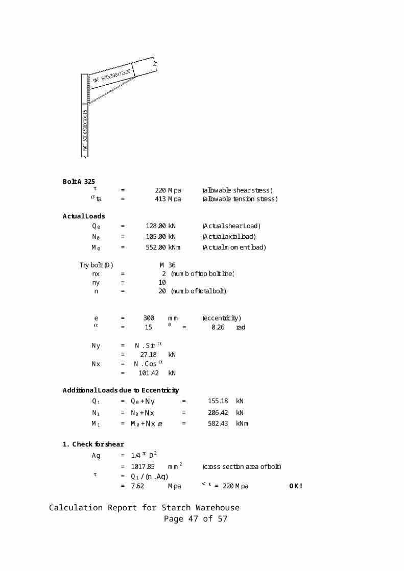
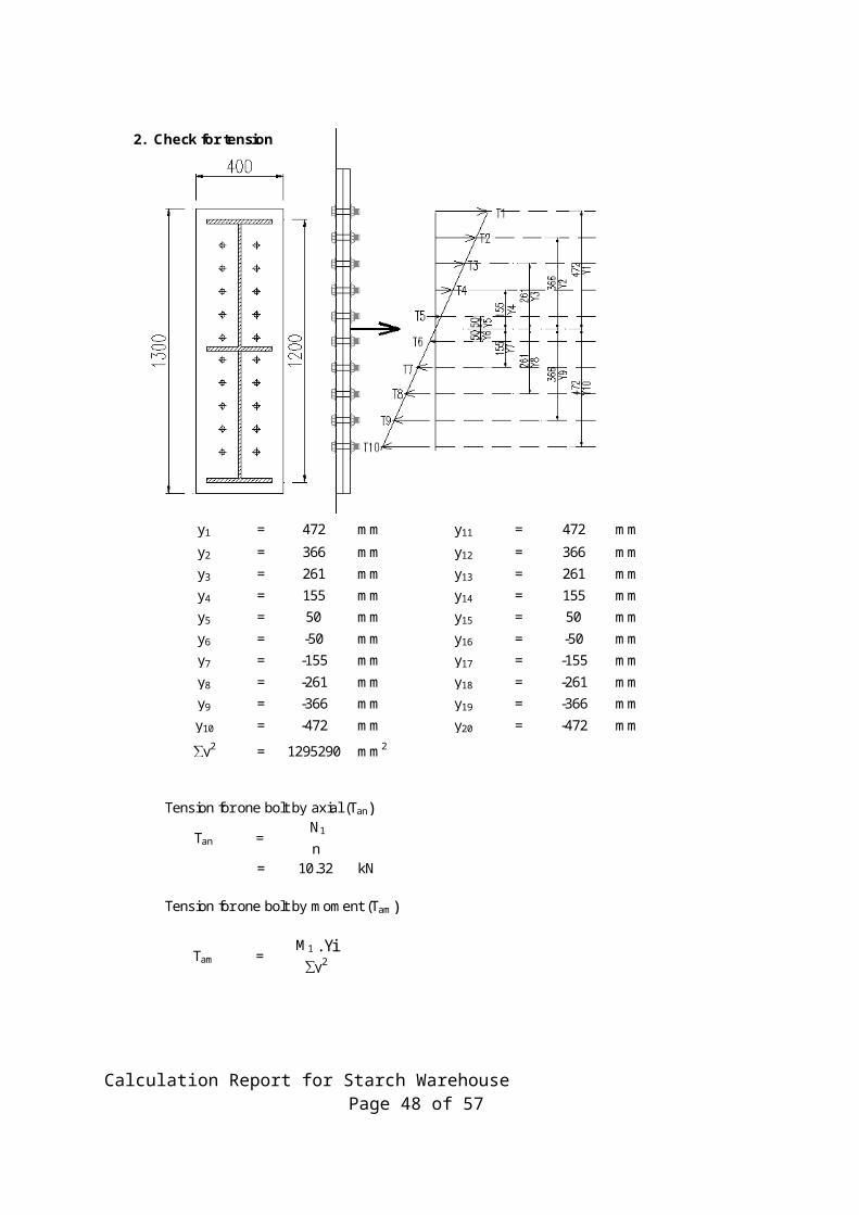
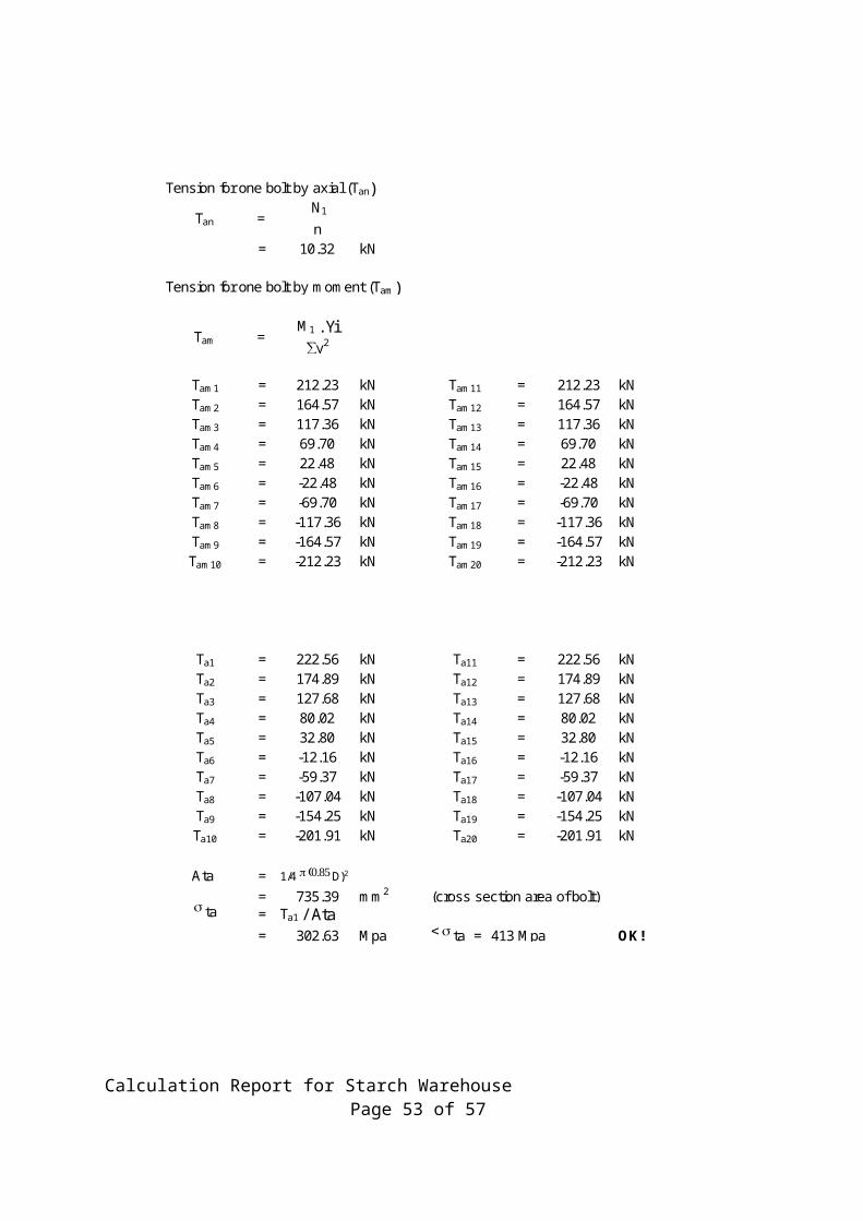
Bolt A 325t = 220 Mpa (allowable shear stress)s ta = 413 Mpa (allowable tension stress)
Actual LoadsQ0 = 128.00 kN (Actual shear Load)N0 = 105.00 kN (Actual axial load)
M0 = 552.00 kNm (Actual moment load)
Try bolt (D) M 36nx = 2 (numb of top bolt line)ny = 10n = 20 (numb of total bolt)
e = 300 mm (eccentricity)a = 15 0 = 0.26 rad
Ny = N . Sin a= 27.18 kN
Nx = N . Cos a= 101.42 kN
Additional Loads due to EccentricityQ1 = Q0 + Ny = 155.18 kN
N1 = N0 + Nx = 206.42 kN
M1 = M0 + Nx .e = 582.43 kNm
1. Check for shearAg = 1/4 p D2
= 1017.85 mm2 (cross section area of bolt)t = Q1 / (n . Ag)
= 7.62 Mpa < t = 220 Mpa OK!
Calculation Report for Starch Warehouse Page 37 of 57

2. Check for tension
y1 = 472 mm y11 = 472 mmy2 = 366 mm y12 = 366 mmy3 = 261 mm y13 = 261 mmy4 = 155 mm y14 = 155 mmy5 = 50 mm y15 = 50 mmy6 = -50 mm y16 = -50 mmy7 = -155 mm y17 = -155 mmy8 = -261 mm y18 = -261 mmy9 = -366 mm y19 = -366 mmy10 = -472 mm y20 = -472 mm
∑y2 = 1295290 mm2
Tension for one bolt by axial (Tan) N1
n = 10.32 kN
Tension for one bolt by moment (Tam)
M1 . Yi∑y2
Tan =
Tam =
Calculation Report for Starch Warehouse Page 38 of 57
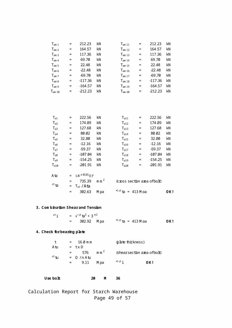
Tam1 = 212.23 kN Tam11 = 212.23 kNTam2 = 164.57 kN Tam12 = 164.57 kNTam3 = 117.36 kN Tam13 = 117.36 kNTam4 = 69.70 kN Tam14 = 69.70 kNTam5 = 22.48 kN Tam15 = 22.48 kNTam6 = -22.48 kN Tam16 = -22.48 kNTam7 = -69.70 kN Tam17 = -69.70 kNTam8 = -117.36 kN Tam18 = -117.36 kNTam9 = -164.57 kN Tam19 = -164.57 kNTam10 = -212.23 kN Tam20 = -212.23 kN
Ta1 = 222.56 kN Ta11 = 222.56 kNTa2 = 174.89 kN Ta12 = 174.89 kNTa3 = 127.68 kN Ta13 = 127.68 kNTa4 = 80.02 kN Ta14 = 80.02 kNTa5 = 32.80 kN Ta15 = 32.80 kNTa6 = -12.16 kN Ta16 = -12.16 kNTa7 = -59.37 kN Ta17 = -59.37 kNTa8 = -107.04 kN Ta18 = -107.04 kNTa9 = -154.25 kN Ta19 = -154.25 kNTa10 = -201.91 kN Ta20 = -201.91 kN
Ata = 1/4 p (0.85 D)2
= 735.39 mm2 (cross section area of bolt)s ta = Ta1 / Ata
= 302.63 Mpa < s ta = 413 Mpa OK!
3. Combination Shear and Tension
s i = √ s ta2 + 3 t2
= 302.92 Mpa < s ta = 413 Mpa OK!
4. Check for bearing plate
t = 16.0 mm (plate thickness)Atu = t x D
= 576 mm2 (shear section area of bolt)s tu = Q / n Atu
= 9.11 Mpa < s i OK!
Use bolt 20 M 36
Calculation Report for Starch Warehouse Page 39 of 57

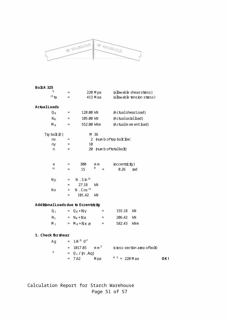
Bolt A 325t = 220 Mpa (allowable shear stress)s ta = 413 Mpa (allowable tension stress)
Actual LoadsQ0 = 128.00 kN (Actual shear Load)
N0 = 105.00 kN (Actual axial load)M0 = 552.00 kNm (Actual moment load)
Try bolt (D) M 36nx = 2 (numb of top bolt line)ny = 10n = 20 (numb of total bolt)
e = 300 mm (eccentricity)a = 15 0 = 0.26 rad
Ny = N . Sin a= 27.18 kN
Nx = N . Cos a= 101.42 kN
Additional Loads due to EccentricityQ1 = Q0 + Ny = 155.18 kN
N1 = N0 + Nx = 206.42 kNM1 = M0 + Nx .e = 582.43 kNm
1. Check for shearAg = 1/4 p D2
= 1017.85 mm2 (cross section area of bolt)t = Q1 / (n . Ag)
= 7.62 Mpa < t = 220 Mpa OK!
Calculation Report for Starch Warehouse Page 40 of 57

2. Check for tension
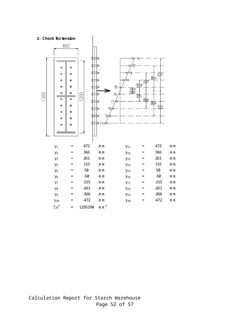
y1 = 472 mm y11 = 472 mm
y2 = 366 mm y12 = 366 mmy3 = 261 mm y13 = 261 mmy4 = 155 mm y14 = 155 mmy5 = 50 mm y15 = 50 mmy6 = -50 mm y16 = -50 mmy7 = -155 mm y17 = -155 mmy8 = -261 mm y18 = -261 mmy9 = -366 mm y19 = -366 mmy10 = -472 mm y20 = -472 mm
∑y2 = 1295290 mm2
Calculation Report for Starch Warehouse Page 41 of 57
Tension for one bolt by axial (Tan) N1
n = 10.32 kN
Tension for one bolt by moment (Tam)
M1 . Yi∑y2
Tam1 = 212.23 kN Tam11 = 212.23 kNTam2 = 164.57 kN Tam12 = 164.57 kNTam3 = 117.36 kN Tam13 = 117.36 kNTam4 = 69.70 kN Tam14 = 69.70 kNTam5 = 22.48 kN Tam15 = 22.48 kNTam6 = -22.48 kN Tam16 = -22.48 kNTam7 = -69.70 kN Tam17 = -69.70 kNTam8 = -117.36 kN Tam18 = -117.36 kNTam9 = -164.57 kN Tam19 = -164.57 kNTam10 = -212.23 kN Tam20 = -212.23 kN
Ta1 = 222.56 kN Ta11 = 222.56 kNTa2 = 174.89 kN Ta12 = 174.89 kNTa3 = 127.68 kN Ta13 = 127.68 kNTa4 = 80.02 kN Ta14 = 80.02 kNTa5 = 32.80 kN Ta15 = 32.80 kNTa6 = -12.16 kN Ta16 = -12.16 kNTa7 = -59.37 kN Ta17 = -59.37 kNTa8 = -107.04 kN Ta18 = -107.04 kNTa9 = -154.25 kN Ta19 = -154.25 kNTa10 = -201.91 kN Ta20 = -201.91 kN
Ata = 1/4 p (0.85 D)2
= 735.39 mm2 (cross section area of bolt)s ta = Ta1 / Ata
= 302.63 Mpa < s ta = 413 Mpa OK!
Tan =
Tam =
Calculation Report for Starch Warehouse Page 42 of 57
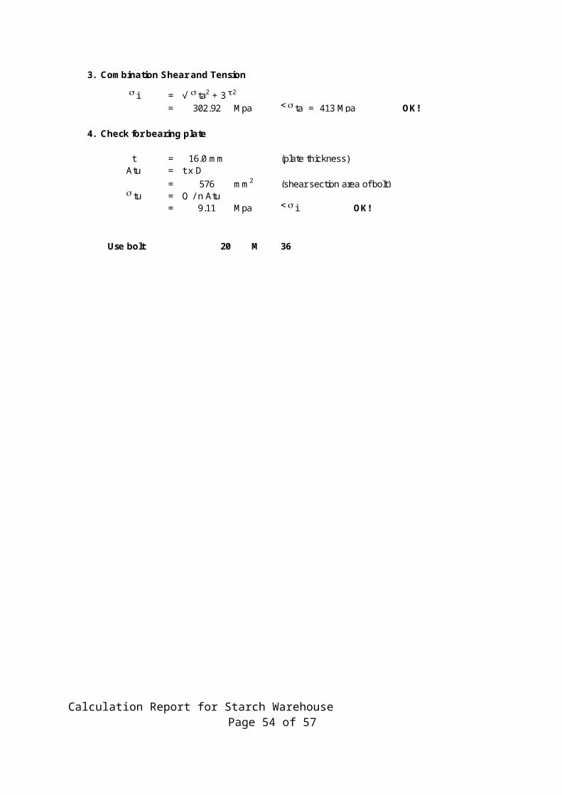
3. Combination Shear and Tension
s i = √ s ta2 + 3 t2
= 302.92 Mpa < s ta = 413 Mpa OK!
4. Check for bearing plate
t = 16.0 mm (plate thickness)Atu = t x D
= 576 mm2 (shear section area of bolt)s tu = Q / n Atu
= 9.11 Mpa < s i OK!
Use bolt 20 M 36
Calculation Report for Starch Warehouse Page 43 of 57

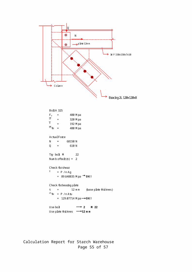
Bolt A 325Fy = 480 Mpas = 320 Mpat = 192 Mpas tu = 480 Mpa
Actual ForceN = 68150 NQ = 610 N
Try bolt M 22Numb of bolt (n) = 2
Check for sheart = P / n Ag
= 89.648835 Mpa OK!
Check for bearing platet = 12 mm (base plate thicknes)s tu = P / n Atu
= 129.07714 Mpa OK!
Use bolt 2 M 22Use plate thicknes 12 mm
Q
N
plate 12mm
IWF 150x150x7x10
Column
Bracing 2L 120x120x8
Calculation Report for Starch Warehouse Page 44 of 57
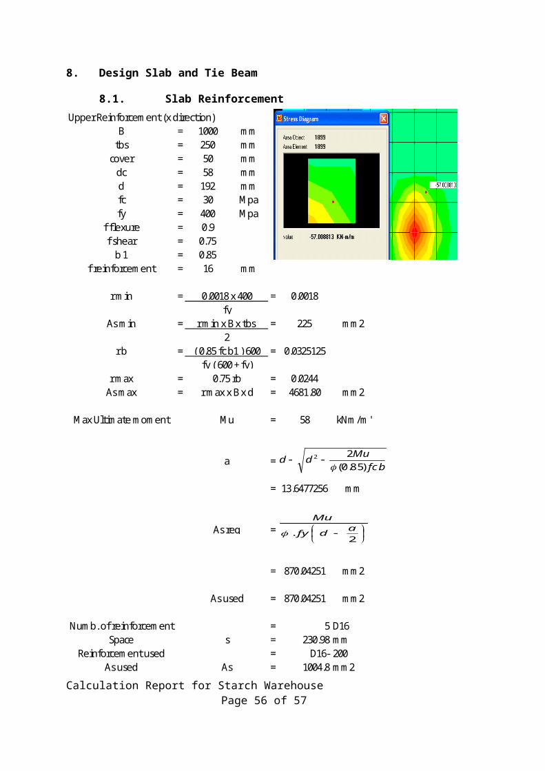
8. Design Slab and Tie Beam
8.1. Slab ReinforcementUpper Reinforcement (x direction)
B = 1000 mmtbs = 250 mm
cover = 50 mmdc = 58 mmd = 192 mmfc = 30 Mpafy = 400 Mpa
f flexure = 0.9f shear = 0.75
b 1 = 0.85f reinforcement = 16 mm
r min = = 0.0018
As min = = 225 mm2
r b = = 0.0325125
r max = = 0.0244As max = = 4681.80 mm2
Max Ultimate moment = 58 kNm/m'
=
= 13.6477256 mm
=
= 870.04251 mm2
= 870.04251 mm2
Numb. of reinforcement = 5 D16Space = 230.98 mm
Reinforcement used = D16- 200As used = 1004.8 mm2
As used
0.0018 x 400fy
r min x B x tbs 2
( 0.85 fc b1 ) 600fy ( 600 + fy)
0.75 rb r max x B x d
Mu
a
As req
s
As
bfcMudd
.)85.0(22
--
-
2. adfy
Mu
Calculation Report for Starch Warehouse Page 45 of 57
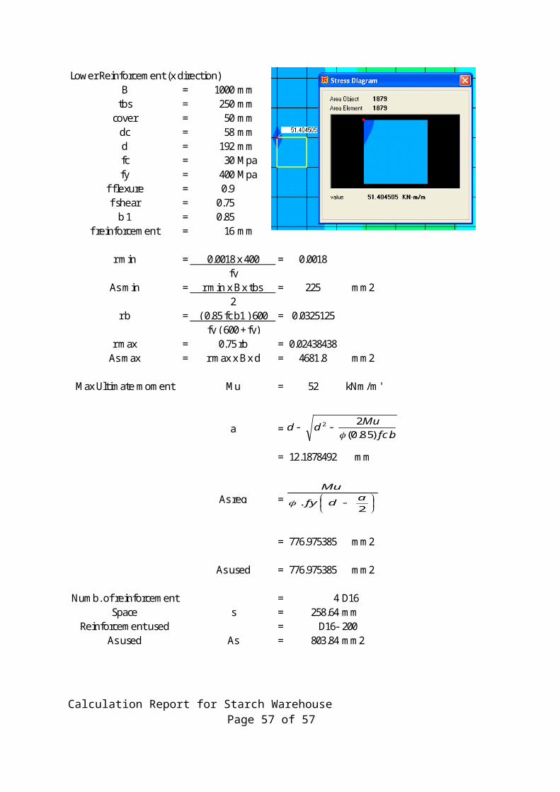
Lower Reinforcement (x direction)B = 1000 mm
tbs = 250 mmcover = 50 mm
dc = 58 mmd = 192 mmfc = 30 Mpafy = 400 Mpa
f flexure = 0.9f shear = 0.75
b 1 = 0.85f reinforcement = 16 mm
r min = = 0.0018
As min = = 225 mm2
r b = = 0.0325125
r max = = 0.02438438As max = = 4681.8 mm2
Max Ultimate moment = 52 kNm/m'
=
= 12.1878492 mm
=
= 776.975385 mm2
= 776.975385 mm2
Numb. of reinforcement = 4 D16Space = 258.64 mm
Reinforcement used = D16- 200As used = 803.84 mm2
a
0.0018 x 400fy
r min x B x tbs 2
( 0.85 fc b1 ) 600fy ( 600 + fy)
0.75 rb r max x B x d
Mu
As req
As used
s
As
bfcMudd
.)85.0(22
--
-
2. adfy
Mu
Calculation Report for Starch Warehouse Page 46 of 57
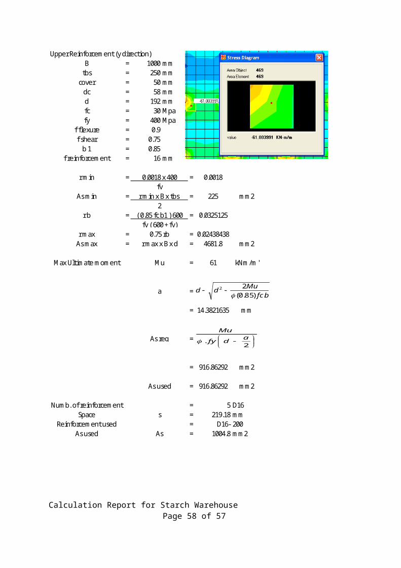
Upper Reinforcement (y direction)B = 1000 mm
tbs = 250 mmcover = 50 mm
dc = 58 mmd = 192 mmfc = 30 Mpafy = 400 Mpa
f flexure = 0.9f shear = 0.75
b 1 = 0.85f reinforcement = 16 mm
r min = = 0.0018
As min = = 225 mm2
r b = = 0.0325125
r max = = 0.02438438As max = = 4681.8 mm2
Max Ultimate moment = 61 kNm/m'
=
= 14.3821635 mm
=
= 916.86292 mm2
= 916.86292 mm2
Numb. of reinforcement = 5 D16Space = 219.18 mm
Reinforcement used = D16- 200As used = 1004.8 mm2
r max x B x d
0.0018 x 400fy
r min x B x tbs 2
( 0.85 fc b1 ) 600fy ( 600 + fy)
0.75 rb
Mu
a
As req
As used
s
As
bfcMudd
.)85.0(22
--
-
2. adfy
Mu
Calculation Report for Starch Warehouse Page 47 of 57
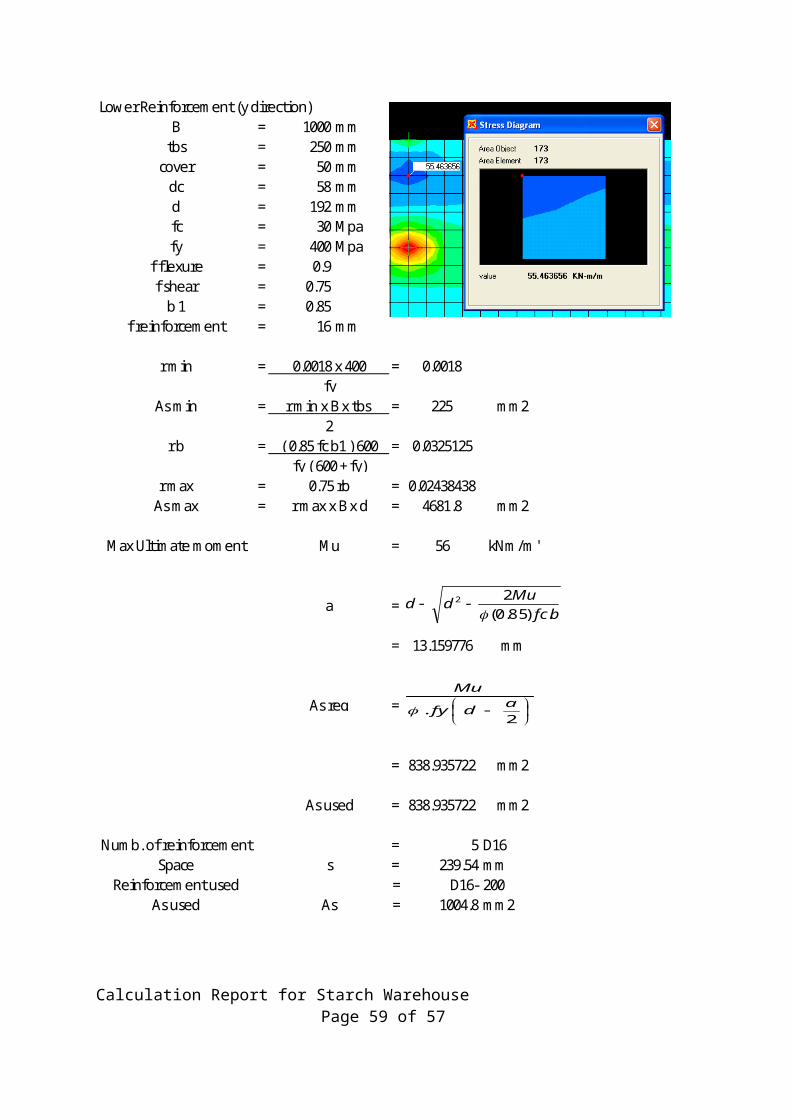
Lower Reinforcement (y direction)B = 1000 mm
tbs = 250 mmcover = 50 mm
dc = 58 mmd = 192 mmfc = 30 Mpafy = 400 Mpa
f flexure = 0.9f shear = 0.75
b 1 = 0.85f reinforcement = 16 mm
r min = = 0.0018
As min = = 225 mm2
r b = = 0.0325125
r max = = 0.02438438As max = = 4681.8 mm2
Max Ultimate moment = 56 kNm/m'
=
= 13.159776 mm
=
= 838.935722 mm2
= 838.935722 mm2
Numb. of reinforcement = 5 D16Space = 239.54 mm
Reinforcement used = D16- 200As used = 1004.8 mm2
fy ( 600 + fy)
0.0018 x 400fy
r min x B x tbs 2
( 0.85 fc b1 ) 600
s
As
0.75 rb r max x B x d
Mu
a
As req
As used
bfcMudd
.)85.0(22
--
-
2. adfy
Mu
Calculation Report for Starch Warehouse Page 48 of 57
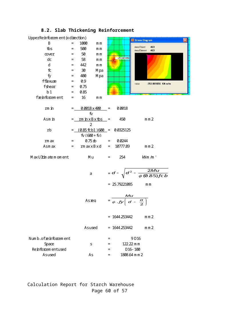
8.2. Slab Thickening ReinforcementUpper Reinforcement (x direction)
B = 1000 mmtbs = 500 mm
cover = 50 mmdc = 58 mmd = 442 mmfc = 30 Mpafy = 400 Mpa
f flexure = 0.9f shear = 0.75
b 1 = 0.85f reinforcement = 16 mm
r min = = 0.0018
As min = = 450 mm2
r b = = 0.0325125
r max = = 0.0244As max = = 10777.89 mm2
Max Ultimate moment = 254 kNm/m'
=
= 25.79221085 mm
=
= 1644.253442 mm2
= 1644.253442 mm2
Numb. of reinforcement = 9 D16Space = 122.22 mm
Reinforcement used = D16- 100As used = 1808.64 mm2
fy ( 600 + fy)
0.0018 x 400fy
r min x B x tbs 2
( 0.85 fc b1 ) 600
0.75 rb r max x B x d
Mu
a
As req
As used
s
As
bfcMudd
.)85.0(22
--
-
2. adfy
Mu
Calculation Report for Starch Warehouse Page 49 of 57

Upper Reinforcement (y direction)B = 1000 mm
tbs = 500 mmcover = 50 mm
dc = 58 mmd = 442 mmfc = 28 Mpafy = 400 Mpa
f flexure = 0.9f shear = 0.75
b 1 = 0.85f reinforcement = 16 mm
r min = = 0.0018
As min = = 450 mm2
r b = = 0.030345
r max = = 0.02275875As max = = 10059.3675 mm2
Max Ultimate moment = 254 kNm/m'
=
= 27.69594876 mm
=
= 1647.908951 mm2
= 1647.908951 mm2
Numb. of reinforcement = 9 D16Space = 121.95 mm
Reinforcement used = D16- 100As used = 1808.64 mm2
2
0.0018 x 400fy
r min x B x tbs
( 0.85 fc b1 ) 600fy ( 600 + fy)
0.75 rb r max x B x d
Mu
a
As req
As used
s
As
bfcMudd
.)85.0(22
--
-
2. adfy
Mu
Calculation Report for Starch Warehouse Page 50 of 57
8.3. Design Tie Beam 400 x 700
1 Design Beam Type B1 (400 mm x 700 mm)
Max 453 15211 255 3910 100 6470Min -453 -15974 -255 -3940 -100 -10063
Beam L/C P(kg) V2 (kg) V3 (kg) T (kg-m) M2 kg-m M3 kg-mMax P 20 5.5 -453 12626 -41 405 -16 -1161Min P 20 5.5 453 12626 41 405 16 -1161
Max V2 20 0 0 -15974 0 -917 0 -10063Min V2 25 6 0 15211 0 385 0 -8476Max V3 29 0.75 -197 -1103 -255 -711 -100 809Min V3 29 0.75 197 -1103 255 -711 100 809Max T 18 5.25 0 1400 0 -3940 0 1421Min T 29 2.25 0 2894 0 3910 0 371
Max M2 29 0.75 -132 -1372 -103 3681 -100 1364Min M2 29 0.75 132 -1372 103 3681 100 1364Max M3 19 6 0 8532 0 -917 0 -10063Min M3 28 3.5 0 469 0 -349 0 6470
B = 400 mm f'c = 30 N/mm2
H = 700 mm fy = 400 N/mm2
cover = 50 mm ρmin = 0.00350
dc = 71 mm As min = 880.6 mm2
d = 629 mm ρb = 0.03251 f lexure = 0.9 ρmax = 0.02438 shear = 0.75 As max = 6135.11 mm2
b c = 0.85 longitudinal = 22 mm transversal = 10 mm
Maximum Ultimate Moment Mu = 10063 kgma = 17.68 mm
As req = 442.0 mm2
Max(As min, As req) = 880.6 mm2
Actual number of reinforcement 4 D 22 As = 1520.53 mm2
Acting stress / Allowable stress = 58% < 80%Used number of reinforcement 4 D 22 As = 1520.53 mm2
Acting stress / Allowable stress = 58% < 80%
Maximum Ultimate Moment Mu = 6470 kgma = 11.31 mm
As req = 282.8 mm2
Max(As min, As req) = 880.6 mm2
Actual number of reinforcement 3 D 22 As = 1140.4 mm2
Acting stress / Allowable stress = 77% < 80%Used number of reinforcement 3 D 22 As = 1140.4 mm2
Acting stress / Allowable stress = 77% < 80%
Calculation Report for Starch Warehouse Page 51 of 57
- Torsion DesignBeam Width (b) : 400 mmBeam Height (h) : 700 mmCover (s) : 50 mmLong. Rebar (dt) : 22 mmTrans. Rebar (dbs) : 10 mmNumber of Legs (n) : 2 pcs
Xo = 400 mm { Xo = beam width (b) }Yo = 700 mm { Yo = beam height (h) }X1 = 290 mm { Xo - ( 2 x cover + ds ) }Y1 = 590 mm { Yo - ( 2 x cover + ds ) }bw = 400 mm { bw = beam width (b) }d = 629.0 mm (h - cover - ds - 0.5dt)fy = 400 N/mm2
f'c = 30 N/mm2
Es = 200000 N/mm2
Ec = 25743 N/mm2
shear = 0.75
Combined Shear and TorsionSee Attachment C-68,Maximum shear (Min V2, Beam 25, L/C 6)
Vu = 15.974 Ton = 156.66 KNMaximum torsion (Max T, Beam 18, L/C 5.2)Tu = 3.940 Ton m = 38.64 KN mfy s = 400 N/mm2
Shear strength provided by concrete
229.68 kN
Vc = 172.26 kN
Vu - Vc = -15.60 kNTransverse reinforcement required for shear alone
0.00 mm2/mm Therefore, shear reinforcement is not necessary
Torsion thresholdAcp = 280000 mm2
Pcp = 2200 mm
1.244 Ton m < Tu = 3.94 Ton m (Provide Torsion Reinforcement)
Determine whether the section is adequate for combined shear and torsionph = 1760 mm
Aoh = 171100 mm2
Ao = 145435 mm2 (A o = 0.85 A oh )
= 1.5021.502 < 3.424, Section is Adequate.
= 3.423
( )oocp Y.XA =
( )'f4700E cc =
( ) 11oh Y.XA =
( ) YoXo2Pcp =
( ) 1Y1X2hP =
=-
=dfVV
sA
ys
cuv
==cp
2cpc
cr PA
12'f
T
2
2oh
hu
2
w
u
A7.1PT
dbV
12'f8
d.bV c
w
c
== d.b.'f61V wcc
Calculation Report for Starch Warehouse Page 52 of 57
Transverse reinforcement required for torsion alone
0.443 mm2/mm where : θ = 45˚
Required reinforcement for shear and torsion
0.886 mm2/m
0.342 mm2/m ≥ = 0.3500 mm2/m
= 0.886 mm2/mDetermined the required spacing of torsional transverse reinforcement
dbs = 10 mmAb = 0.25 π dbs
2 = 78.54 mm2
Av prov ided = 2 Ab = 157.08 mm2
177.38 mm
Maximum permissible transverse reinforcement in edge Beama. d/4 = 157b. 8 x Diameter longitudinal= 176 c. 24 x Diameter strirrups = 315 mmd. 300mm = 300 mm
Min Spacing = 150 mmTake transverse reinforcement :
D 10 - 100 As = 1178.1 - mm2/m mm2/m
Maximum permissible transverse reinforcement in Middle Beamd/2 = 314.5 mmTake srequired = = 200 mmTake transverse reinforcement :
D 10 - 200 As = 589.05 - mm2/m mm2/mAdditional longitudinal torsion reinforcement
= 779.30 mm2 ≥ ALmin ( θ = 45 ° )
= 818.23 mm2
and 0.443 mm shall not be less than 0.175 mm2/mm
AL = 818.23 mm2
Take additional longitudinal torsion reinforcement :Bottom bar as Torsional reinforcement
Av provided
=
=
yso
ut
f.A.2tanT
sA
==sA2
sA
sA tvT min
sA tv
==ys
wctv
f16b'f
minsA
ys
w
f20b7
==
sA
As
T
providedvd'req
θcotff
psA
A 2
y
ysh
tL
=
y
ysh
t
y
cpcminL f
fp
sA
f12A'f5
A
= -
=sAt =
ys
w
fb
175.0
s/AT
Calculation Report for Starch Warehouse Page 53 of 57
Top reinforcement =1 - D 22 As = 380.1 mm2
Bottom reinforcement =1 - D 22 As = 380.1 mm2
Side reinforcement =4 - D 19 As = 1134.1 mm2
Total Torsional Reinforcement = 1894.4 mm2 , OK< Tu = 3.94 Ton m (Provide Torsion Reinforcement)
Check for bar spacingfy = 400 N/mm2
smax = Spacing of reinforcement fs = 2/3 fy = 267 N/mm2
cc = least distance from surface of reinforcement to the tension face
= 50 mm
(Chapter 10.6.4 - ACI 318 05)
smax = 274 mm ≤ 315 mm → OKn = 5 (no. of bar in tension)
= 64.5 mm < 274 mm OK
smin = max(db,25)+db
= 47 mm < 64.5 mm OK
Type B1 reinforcement summary (Edge Beam)Flexure Shear
Rebar req.area req.spcg As min As max S min S max Rebar As SpcgLocation mm2 mm mm2 mm2 mm mm mm2 mm
Top 442 - 881 6135 47 274 5 D22 1901 65Side - - - - - - 4 D19 1134 -
Bottom - - 881 6135 47 274 3 D22 1140 129Stirrups - 177 - - - 157 D10 - 100
Type B1 reinforcement summary (Middle Beam)Flexure Shear
Rebar req.area req.spcg As min As max S min S max Rebar As SpcgLocation mm2 mm mm2 mm2 mm mm mm2 mm
Top - - 881 6135 47 274 3 D22 1901 129Side - - - - - - 4 D19 1134 -
Bottom 283 - 881 6135 47 274 5 D22 1140 65Stirrups - 177 - - - 315 D10 - 200
2/3 x 490 =
Actual
Actual
q = Mx . Zi
cc cc
dbs+0.5db
sact
-
=
sc
smax f
280300c5.2f
280380s
( )
-
=
327280300805.2
327280380
( )1n
d5.0dc2bs bbscact -
-=
Calculation Report for Starch Warehouse Page 54 of 57
9. Design Foundation
9.1. Pile Cap with 1 Pile
pile cap (b1 x l1 x h1)
square pile (b2 x h2)
x
y
b1
l1
h1
b
b2
sx
column dimensionb = 350 mmh = 350 mmpile cap dimensionl1 = 1050 mmb1 = 1050 mmh1 = 600 mmsquare pile dimensionb2 = 350 mmh2 = 350 mmsx = 0 mml = 20 m (length of spun pile)Shear checkPu = 28 ton (axial support reaction)Vn = Pu /
= 33 tonf'c = 30 Mpat = 100 mm (cover)D1 = 16 mm (first layer reinforcement diameter)d1 = h1 - t - D1 / 2
= 492 mmbo = 2 x (b + h + 2d1)
= 3368 mmbc = b/h
= 1Vc = 1/6 x f'c x (1 + 2/bc) xbo x d1
= 4538 kN= 454 ton
Vn < Vc --> OK!
Calculation Report for Starch Warehouse Page 55 of 57
Pile cap reinforcementSupport reactionPuz = 27.8 tonMux = 1.140 ton m
Muy = 0.078 ton m
Pile cap weightPc = 1.6 tonPuc = 2 ton
Spun pile eccentricitylx = 0.18 m
MomentMux' = 1.14 ton mMuy' = (Puz / 2) x lx + (Muy / sx) x lx + (Puc/2) x lx
= 2.63 ton m
X-direction reinforcementfy = 400 Mpa
a = d1 - d12 - 2 x Muy' F x 0.85 x f'c x b1
= 2.2 mm
Asx = Muy'F x fy x (d1 - a/2)
= 149 mm2
Asmin = 0.0018 x b1 x d1= 1134 mm2
Asused = 1134 mm2
x-direction reinforcement D 16 - 186 mmD 16 - 150 mm
Y-direction reinforcementfy = 400 MpaD2 = 16 mm (second layer reinforcement diameter)d2 = h1 - t - D1 - D2 / 2
= 234 mma = d2 - d22 - 2 x Mux'
F x 0.85 x f'c x l1= 1.9 mm
Asy = Mux'F x fy x (d2 - a/2)
= 136 mm2
Asmin = 0.0035 x l1 x d2= 860 mm2
Asused = 859.95 mm2
y-direction reinforcement D 16 - 245 mmD 16 - 150 mm
Calculation Report for Starch Warehouse Page 56 of 57
9.2. Pile Cap with 2 Piles
column (b x h)
pile cap (b1 x l1 x h1)
square pile (b2 x h2)
y
x
b1
l1
h1
sx
b
b2b2 .column dimensionb = 450 mmh = 450 mmpile cap dimensionl1 = 2100 mmb1 = 1050 mmh1 = 600 mmspun pile dimensionb2 = 350 mmh2 = 350 mmsx = 1050 mml = 20 m (length of spun pile)Shear checkPu = 67 ton (axial support reaction)Vn = Pu /
= 79 tonf'c = 30 Mpat = 100 mm (cover)D1 = 16 mm (first layer reinforcement diameter)d1 = h1 - t - D1 / 2
= 492 mmbo = 2 x (b + h + 2d1)
= 3768 mmbc = b/h
= 1Vc = 1/6 x f'c x (1 + 2/bc) xbo x d1
= 5077 kN= 508 ton
Vn < Vc --> OK!
Calculation Report for Starch Warehouse Page 57 of 57
Pile cap reinforcementSupport reactionPuz = 67.5 tonMux = 1.410 ton m
Muy = 3.198 ton m
Pile cap weightPc = 3.2 tonPuc = 4 ton
Spun pile eccentricitylx = 0.53 m
MomentMux' = 1 ton mMuy' = (Puz / 2) x lx + (Muy / sx) x lx + (Puc/2) x lx
= 20 ton m
X-direction reinforcementfy = 400 Mpa
a = d1 - d12 - 2 x Muy' F x 0.85 x f'c x b1
= 17.6 mm
Asx = Muy'F x fy x (d1 - a/2)
= 1177 mm2
Asmin = 0.0018 x b1 x d1= 1134 mm2
Asused = 1176.83 mm2
x-direction reinforcement D 16 - 179 mmD 16 - 150 mm
Y-direction reinforcementfy = 400 MpaD2 = 16 mm (second layer reinforcement diameter)d2 = h1 - t - D1 - D2 / 2
= 234 mma = d2 - d22 - 2 x Mux'
F x 0.85 x f'c x l1= 0.5 mm
Asy = Mux'F x fy x (d2 - a/2)
= 168 mm2
Asmin = 0.0035 x l1 x d2= 1720 mm2
Asused = 1719.9 mm2
y-direction reinforcement D 16 - 245 mmD 16 - 150 mm
Calculation Report for Starch Warehouse Page 58 of 57
9.3. Pile Cap with 3 Piles
l1sy
b1
B
h1
sx
b2
COLUMN (B x H)
PILECAP (b1 x l1 x h1)
PILE
Pedestal DimensionB = 550 mmH = 550 mm
Pile Cap Dimensionl1 = 1939 mm Area = 4508072.2 mm2b1 = 2100 mmh1 = 600 mm
Pile Dimensionb2 = 350 mmh2 = 350 mmsx = 1200 mm
sy = 1039 mmL = 20 m
Shear CheckPu = 35.5 Ton
f'c = 30 MPa
fy = 400 Mpacover = 100 mmD1 = 19 mmD2 = 16 mmbc = b/h = 1
d1 = h1 - cover - D1 / 2 = 491 mm
d2 = h1 - cover - D1 - D2 / 2 = 473 mm
bo = 2 x (b + h + 2d1) = 4162 mm
Vn = Pu / = 42 Ton
Vc = 1/6 x f'c x (1 + 2/bc) x bo x d1
= 559 Ton
Check,Vn < Vc
42 < 559 Remark = OK
Calculation Report for Starch Warehouse Page 59 of 57
Pile cap reinforcementSupport reactionPuz = 35.5 Ton
Mux = 1.410 Ton mMuy = 2.028 Ton m
Pile cap weightPc = 6.492 Ton
Puc = 9.088 Ton
Eccentricitylx = 0.33 mm
ly = 0.24 mm
MomentMux' = 2 (Puz/3) ly + (Mux/sy ) ly + 2 (Puc/3) ly = 7.600 Ton mMuy ' = (Puz/3) lx + (Muy /sx) lx + (Puc/3) lx = 5.380 Ton m
Bottom reinforcement
a = d1 d12 2 Mux = 3.2 mm
φ x 0.85 x f'c x bw
Asx = Muy = 432 mm2
φ x fy x (d1 - a/2)
Asmin = 0.0018 x b1 x d1 = 2268 mm2
Astake = MAX(Asmin , Asx) = 2268 mm2
First Layer (X - Direction), D19 - 262Reinforcement, take : D19 - 150
Top reinforcement
a = d2 d22 2 Muy = 1.8 mm
φ x 0.85 x f'c x bw
Asy = Muy = 317 mm2
φ x fy x (d2 - a/2)
Asmin = 0.0018 x l1 x d2 = 1651 mm2
Astake = MAX (Asmin , Asy ) = 1650.865 mm2
Second Layer (Y - Direction), D16 - 236Reinforcement, take : D16 - 150
Calculation Report for Starch Warehouse Page 60 of 57


![[04899] - Design of Pile & Pile-Cap](https://static.fdocuments.in/doc/165x107/5695d3331a28ab9b029d273d/04899-design-of-pile-pile-cap.jpg)