ITA Calibration Laboratory - mechanik.media.pl · EN ISO 527-1 or metals according to PN-EN ISO...
4
MECHANIK NR 5–6/2018 How to cite this article: Authors: Józef Gruszka, Michał Wieczorowski, Barbara Śmierzchalska, Maciej Szelewski, Ireneusz Zachwiej, Damian Śmierzchalski Title of article: „Laboratorium Wzorcujące ITA” (“ITA Calibration Laboratory”) Mechanik, Vol. 91, No. 5–6 (2018): pages 430–433 DOI: https://doi.org/10.17814/mechanik.2018.5-6.53 ITA Calibration Laboratory Laboratorium Wzorcujące ITA JÓZEF GRUSZKA MICHAŁ WIECZOROWSKI BARBARA ŚMIERZCHALSKA MACIEJ SZELEWSKI IRENEUSZ ZACHWIEJ DAMIAN ŚMIERZCHALSKI * In the paper a process of implementation of management system according to PN-EN ISO/IEC 17025 for ITA Calibration Laboratory was presented. Laboratory was granted an accreditation from PCA regarding calibration of universal testing machines and technological devices for tensile forces and compression forces as well as coordinate measuring systems with optical distance sensors and coordinate measuring systems based on technique of optical scanners for rotary symetrical work pieces. KEYWORDS: accredited calibration laboratory, universal testing machines and technological devices for tensile forces and compression forces, coordinate optical measuring systems ITA is a Polish company that has been providing comprehensive measurement and tool solutions for around 20 years. These solutions enable high accuracy measurements, the results of which are used to ensure the quality of finished products. Offered instruments and systems are used in passive and active control systems - both during the production process and in laboratory research - including in enterprises from the automotive, aerospace, weaponry, and plastics industries. In addition to the sales activities, the company has developed service activities in the field of service, installation, training and measurement on behalf of clients. Recently, this part of the activity has been expanded thanks to the establishment of an independent and impartial unit - the ITA Calibration Laboratory, which calibrates measuring instruments with full confidentiality of information and property rights of clients, including protection of electronic collection and transmission of results. The ITA Calibration Laboratory is accredited by PCA No. AP 181 (fig. 1) and meets the requirements of PN-EN ISO/IEC 17025: 2005 Ap1: 2007 [1,2]. The laboratory employs qualified specialists in the field of calibration and periodic testing of strength . ________________ * Dr hab. inż. Józef Gruszka, prof. nadzw. PP (jozef.gruszka@put. poznan.pl) – Politechnika Poznańska, Wydział Inżynierii Zarządzania, Katedra Ergonomii i Inżynierii Jakości; prof. dr hab. inż. Michał Wieczorowski ([email protected]) – Politechnika Poznańska, Instytut Technologii Mechanicznej, Zakład Metrologii i Systemów Pomiarowych; mgr inż. Barbara Śmierzchalska (bc@ita- polska.com.pl), dr inż. Maciej Szelewski (msz@ita-polska.com.pl), mgr inż. Ireneusz Zachwiej (iz@ita-polska.com.pl), mgr inż. Damian Śmierzchalski (ds@ita-polska.com.pl) – ITA machines and technological devices for tensile and compressive forces, as well as coordinate measuring systems with optical measuring head, measuring distance, and optical-based scanners for rotational symmetric elements. Fig. 1. Certificate of the ITA Calibration Laboratory
Transcript of ITA Calibration Laboratory - mechanik.media.pl · EN ISO 527-1 or metals according to PN-EN ISO...

MECHANIK NR 5–6/2018
How to cite this article:
Authors: Józef Gruszka, Michał Wieczorowski, Barbara Śmierzchalska, Maciej Szelewski, Ireneusz Zachwiej, Damian Śmierzchalski
Title of article: „Laboratorium Wzorcujące ITA” (“ITA Calibration Laboratory”)
Mechanik, Vol. 91, No. 5–6 (2018): pages 430–433
DOI: https://doi.org/10.17814/mechanik.2018.5-6.53
ITA Calibration Laboratory
Laboratorium Wzorcujące ITA
JÓZEF GRUSZKA MICHAŁ WIECZOROWSKI BARBARA ŚMIERZCHALSKA MACIEJ SZELEWSKI IRENEUSZ ZACHWIEJ DAMIAN ŚMIERZCHALSKI *
In the paper a process of implementation of management system according to PN-EN ISO/IEC 17025 for ITA Calibration Laboratory was presented. Laboratory was granted an accreditation from PCA regarding calibration of universal testing machines and technological devices for tensile forces and compression forces as well as coordinate measuring systems with optical distance sensors and coordinate measuring systems based on technique of optical scanners for rotary symetrical work pieces. KEYWORDS: accredited calibration laboratory, universal testing machines and technological devices for tensile forces and compression forces, coordinate optical measuring systems
ITA is a Polish company that has been providing comprehensive measurement and tool solutions for around 20 years. These solutions enable high accuracy measurements, the results of which are used to ensure the quality of finished products. Offered instruments and systems are used in passive and active control systems - both during the production process and in laboratory research - including in enterprises from the automotive, aerospace, weaponry, and plastics industries.
In addition to the sales activities, the company has developed service activities in the field of service, installation, training and measurement on behalf of clients. Recently, this part of the activity has been expanded thanks to the establishment of an independent and impartial unit - the ITA Calibration Laboratory, which calibrates measuring instruments with full confidentiality of information and property rights of clients, including protection of electronic collection and transmission of results. The ITA Calibration Laboratory is accredited by PCA No. AP 181 (fig. 1) and meets the requirements of PN-EN ISO/IEC 17025: 2005 Ap1: 2007 [1,2]. The laboratory employs qualified specialists in the field of calibration and periodic testing of strength .
________________ * Dr hab. inż. Józef Gruszka, prof. nadzw. PP (jozef.gruszka@put.
poznan.pl) – Politechnika Poznańska, Wydział Inżynierii Zarządzania, Katedra Ergonomii i Inżynierii Jakości; prof. dr hab. inż. Michał
Wieczorowski ([email protected]) – Politechnika
Poznańska, Instytut Technologii Mechanicznej, Zakład Metrologii i Systemów Pomiarowych; mgr inż. Barbara Śmierzchalska (bc@ita-
polska.com.pl), dr inż. Maciej Szelewski ([email protected]), mgr
inż. Ireneusz Zachwiej ([email protected]), mgr inż. Damian
Śmierzchalski ([email protected]) – ITA
machines and technological devices for tensile and compressive forces, as well as coordinate measuring systems with optical measuring head, measuring distance, and optical-based scanners for rotational symmetric elements.
Fig. 1. Certificate of the ITA Calibration Laboratory

MECHANIK NR 5–6/2018
Process of implementing a management system in the laboratory in accordance with PN-EN ISO/IEC17025
The most difficult step was the first step, namely the
development and subsequent implementation of the quality assurance system in the laboratory. The PN-EN ISO/IEC 17025: 2005 standard specifies the requirements for the development and implementation of the system, as well as the conditions that must be met in order for the Polish Center for Accreditation (PCA) to recognize the competence of the laboratory to perform calibrations [3]. Nevertheless, for the team of laboratory employees, these were new issues requiring supplementing knowledge about management systems and procedural approach to the calibration process. The issue was hampered by the lack of a standardized method of calibration of optical scanners for rotational symmetric elements and the necessity to carry out inter-laboratory tests, it was also problematic to develop methods for estimating the measurement uncertainty and determining the CMC values. The development of the calibration methodology based on the new edition of PN-EN ISO 7500-1: 2016 [4] was also a novelty for the team responsible for force measurements.
The preparation of the accreditation laboratory has been divided into several stages:
1. Decision made by ITA management, determination of the laboratory's organizational structure and selection of personnel.
2. Determining the areas and objects of calibration and list of works that should be undertaken and performed in terms of the degree of compliance with the requirements of PN-EN ISO/IEC 17025 and the PCA documentation.
3. Conducting specialized trainings thematically related to the requirements of PN-EN ISO/IEC 17025: 2005 Ap1: 2007 and PCA documentation.
4. Development of quality policy, quality book, system and technical procedures and other documents.
5. Implementation of the rules of conduct and their verification as part of internal audits.
6. Execution of internal and external orders in the scope of planned calibrations.
7. Conducting inter-laboratory tests and final determination of principles for calculating measurement uncertainty and CMC values.
8. Review of laboratory documentation according to PCA forms (FAP-02 and FAP-03) and preparation of a list of changes and works that should be taken and performed before submitting the application for PCA accreditation.
9. Submitting a formal accreditation application and submitting the laboratory to the audit of the accreditation body.
The laboratory's assessment in the accreditation process consisted in the review by the PCA auditing team of the laboratory's documentation and on the assessment of the laboratory's competence to implement the activity submitted for accreditation. On the basis of the final evaluation report and reported nonconformities, a corrective action program was developed, which after the implementation and evaluation by the PCA auditing team allowed for the decision to accredit the laboratory.
Scope of activity of the calibration laboratory
The ITA Calibration Laboratory on March 13, 2018
received PCA accreditation - AP number 181 - and operates in accordance with the implemented management system according to PN-EN ISO/IEC 17025: 2005. The laboratory operates at its permanent (S) and outside (P) premises and covers the following areas of accreditation:
strength and torque of force (12.01) and associated objects covered by the calibration:
- testing machines for static tests for tensile forces, - testing machines for static tests for compressive forces, - technological devices for tensile forces, - technological devices for compressive forces,
geometric quantities (6.04) in the field of coordinate measurements:
- with an optical measuring head measuring the distance, - coordinate measuring systems based on the technique of optical scanners for rotational symmetric elements. The uncertainty of CMC measurement is referred to as
extended uncertainty. The value expressed in percent is determined in relation to the measuring range of the measured quantity. In other cases, the CMC is expressed in units of measurand.
Fig. 2. Inspekt table 50 kN testing machine for calibration of technological devices (e.g. dynamometers) in the customer's premises or in the ITA laboratory
Universal testing machines (fig. 2) are very common
measuring devices, used in many plants regardless of the industry. They can be used for testing materials with standardized methods, eg plastics in accordance with PN-EN ISO 527-1 or metals according to PN-EN ISO 6892-1. Often, they are also tested on the strength of parts or parts of structures and finished products. In both applications, there are machines with different measuring ranges, allowing to obtain power from a few N to hundreds or even thousands of kN. The complementary equipment are technological devices for measuring force, more often referred to as dynamometers, force gauges or force sensors. The calibration of all these devices takes place in accordance with the PN-EN ISO 7500-1 standard, which precisely describes both the checking procedure and the requirements for measuring systems. The ITA Laboratory uses two methods of verification of machines and sensors:
real force constant method,
constant force indication method. In the first case, mainly concerning devices with the
measuring range up to 100 N, the procedure consists in comparing the indication of force with the mass of a suspended weight or placed on a measuring system expressed in force units. The second method gives wider possibilities, because the tested strength machine introduces the force, and its verification is served by a reference gauge. The ITA Laboratory can be proud of using
MECHANIK NR 5–6/2018
the highest-class reference load cells, i.e. meeting the requirements of class 00 of the PN-EN ISO 376 standard, to which the PN-EN ISO 7500-1 standard refers.
Most tasks are carried out in the workplace of calibrated machines, which is partly dictated by the convenience of users, but above all results from the limitations imposed by the referenced international documents. In the case of technological equipment, the procedure can also be carried out in the ITA laboratory. This is an attractive proposition especially for users of portable devices up to 50 kN. As an auxiliary equipment in the calibration process, the Inspekt table 50 kN testing machine (manufactured by the German company Hegewald und Peschke MPT GmbH) is used, which accurately and gradually introduces the load on the tested gauge to verify the correctness of the indications. Thanks to the compact design, the Inspekt table 50 kN allows you to provide a unique service of calibration of technological devices, including portable force sensors in the customer's laboratory. This proposal is aimed mainly at the aviation industry, where it is often unacceptable to provide control and measuring equipment outside of its own headquarters, even for the needs of calibration by an accredited laboratory.
Optical coordinate scanners belong to coordinate measuring systems, and their checking is devoted to the eighth part of ISO 10360. These devices are widely used in various industries and enable comprehensive dimensional control of manufactured components [5]. Optical coordinate scanners can operate on the basis of structural or laser light, and the location of measuring points is based on triangulation. Fig. 3 shows an example of a HandySCAN 700 portable laser triangulation scanner. When scanning the surface of the object, a laser line system is projected. The lines after reflection from the scanned surface return to the matrix. When a constant distance is known between the laser source and the matrix and the angle between them, you can specify the coordinates of individual points describing the geometry being scanned. While maintaining the optimal scanner distance from the scanned surface, the user will collect nearly half a million points in a second. The collected measuring points are converted into a mesh of triangles, and then these data are compared with the nominal data in the form of CAD models. As a result of the comparison, the user receives deviations in the form of, for example, a color map (fig. 4). During scanning, the scanner can be freely moved around the object through the reference points glued on its surface, observed by the system of two fast cameras [6].
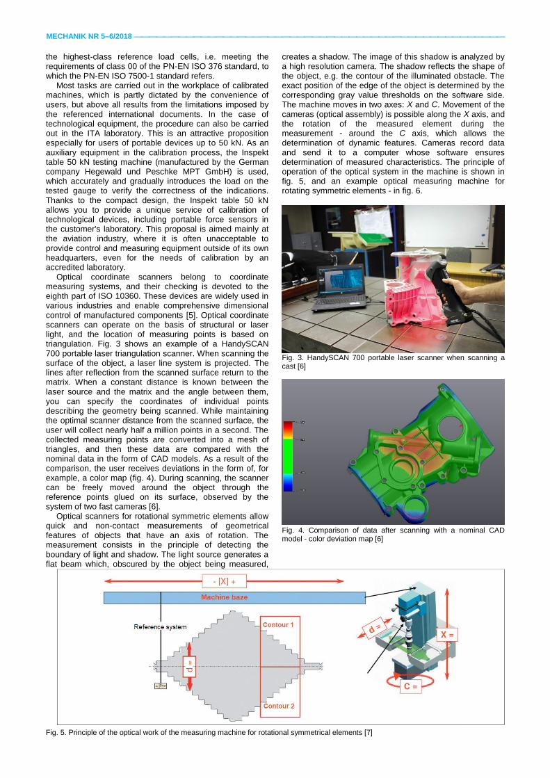
Optical scanners for rotational symmetric elements allow quick and non-contact measurements of geometrical features of objects that have an axis of rotation. The measurement consists in the principle of detecting the boundary of light and shadow. The light source generates a flat beam which, obscured by the object being measured,
creates a shadow. The image of this shadow is analyzed by a high resolution camera. The shadow reflects the shape of the object, e.g. the contour of the illuminated obstacle. The exact position of the edge of the object is determined by the corresponding gray value thresholds on the software side. The machine moves in two axes: X and C. Movement of the cameras (optical assembly) is possible along the X axis, and the rotation of the measured element during the measurement - around the C axis, which allows the determination of dynamic features. Cameras record data and send it to a computer whose software ensures determination of measured characteristics. The principle of operation of the optical system in the machine is shown in fig. 5, and an example optical measuring machine for rotating symmetric elements - in fig. 6.
Fig. 3. HandySCAN 700 portable laser scanner when scanning a cast [6]
Fig. 4. Comparison of data after scanning with a nominal CAD model - color deviation map [6]
Fig. 5. Principle of the optical work of the measuring machine for rotational symmetrical elements [7]

MECHANIK NR 5–6/2018
Fig. 6. Optical Opticline measuring machine [8]
Conclusions
It turned out that the knowledge and experience of employees are the main values of the ITA company that contributed to the final success: appointment and accreditation of an independent, impartial unit - the ITA Calibration Laboratory. One can ask the question: Was it worth making a decision about introducing a management system in a laboratory, since the procedures are labor-intensive and often require considerable time and money? The answer is one: YES, because this is another element of ITA's strategy and the fulfillment of the expectations of many of its clients. Already today, work has begun on adapting the laboratory management system to the requirements of the new ISO/IEC 17025: 2017 standard [9].
REFERENCES 1. PN-EN ISO/IEC 17025:2005 Ap1:2007 Ogólne wymagania
dotyczące kompetencji laboratoriów badawczych i wzorcują-cych.
2. Zakres akredytacji nr AP 181 udzielonej ITA Spółka z ograni-czoną odpowiedzialnością Sp.k. Skórzewo, ul. Poznańska 104, 60-185 Poznań przez Polskie Centrum Akredytacji w dniu 13.03.2018 r. z terminem ważności certyfikatu 12.03.2022 r.: https://www.pca.gov.pl/akredytowane-podmioty/akredytacje-aktywne/laboratoria-wzorcujace (dostęp: 07.04.2018 r.).
3. Dokumenty dotyczące laboratorium wzorcującego, FAP-02, FAP-03: https://www.pca.gov.pl/akredytacja-przewodnik/krok-1-2/laboratoria-wzorcujace/ (dostęp: 07.04.2018 r.).
4. PN-EN ISO 7500-1:2016-02 (wersja angielska) Metale – Wzorcowanie i sprawdzanie statycznych jednoosiowych ma-szyn wytrzymałościowych – Część 1: Maszyny wytrzymało-ściowe rozciągające/ściskające – Wzorcowanie i sprawdzanie układu pomiarowego siły.
5. Wieczorowski M., Szelewski M. „Inżynieria odwrotna i metody dyskretyzacji obiektów fizycznych”. Mechanik. 12 (2015): K183-K188.
6. Materiały firmy Creaform, Kanada. 7. Zachwiej I. „Uniwersalność optycznych maszyn pomiarowych”,
Kalisz: PWSZ Kalisz, Wydział Politechniczny, 2015. 8. Materiały firmy Jenoptik, Niemcy. 9. ISO/IEC 17025:2017 (wersja angielska) General requirements
for the competence of testing and calibration laboratories. ■
■
Translation of scientific articles, their computer composition and publishing them on the website www.mechanik.media.pl by original articles in Polish is a task financed from the funds of the Ministry of Science and Higher Education designated for dissemination of science.


![Accepted ManuscriptAccording to standard PN-EN ISO 6892-1 [19], tensile test can be performed for specimens with round and rectangular cross section. Tensile specimens with …](https://static.fdocuments.in/doc/165x107/6146b52ff4263007b1355a1d/accepted-according-to-standard-pn-en-iso-6892-1-19-tensile-test-can-be-performed.jpg)