it-gost.ru · ISO/IEC 20926:2003(E) © ISO/IEC 2003 – All rights reserved iii Table of Contents...
356
Reference number ISO/IEC 20926:2003(E) © ISO/IEC 2003 INTERNATIONAL STANDARD ISO/IEC 20926 First edition 2003-10-01 Software engineering — IFPUG 4.1 Unadjusted functional size measurement method — Counting practices manual Ingénierie du logiciel — Méthode de mesure de la taille fonctionnelle non ajustée de IFPUG 4.1 — Manuel des pratiques de comptage
Transcript of it-gost.ru · ISO/IEC 20926:2003(E) © ISO/IEC 2003 – All rights reserved iii Table of Contents...
Reference numberISO/IEC 20926:2003(E)
© ISO/IEC 2003
INTERNATIONAL STANDARD
ISO/IEC20926
First edition2003-10-01
Software engineering — IFPUG 4.1 Unadjusted functional size measurement method — Counting practices manual
Ingénierie du logiciel — Méthode de mesure de la taille fonctionnelle non ajustée de IFPUG 4.1 — Manuel des pratiques de comptage

ISO/IEC 20926:2003(E)
PDF disclaimer This PDF file may contain embedded typefaces. In accordance with Adobe's licensing policy, this file may be printed or viewed but shall not be edited unless the typefaces which are embedded are licensed to and installed on the computer performing the editing. In downloading this file, parties accept therein the responsibility of not infringing Adobe's licensing policy. The ISO Central Secretariat accepts no liability in this area.
Adobe is a trademark of Adobe Systems Incorporated.
Details of the software products used to create this PDF file can be found in the General Info relative to the file; the PDF-creation parameters were optimized for printing. Every care has been taken to ensure that the file is suitable for use by ISO member bodies. In the unlikely event that a problem relating to it is found, please inform the Central Secretariat at the address given below.
© ISO/IEC 2003 All rights reserved. Unless otherwise specified, no part of this publication may be reproduced or utilized in any form or by any means, electronic or mechanical, including photocopying and microfilm, without permission in writing from either ISO at the address below or ISO's member body in the country of the requester.
ISO copyright office Case postale 56 • CH-1211 Geneva 20 Tel. + 41 22 749 01 11 Fax + 41 22 749 09 47 E-mail [email protected] Web www.iso.org
Published in Switzerland
ii © ISO/IEC 2003 – All rights reserved

ISO/IEC 20926:2003(E)
© ISO/IEC 2003 – All rights reserved iii
Table of Contents
Foreword......................................................................................................................vii Scope ..........................................................................................................................viii IFPUG Foreword...........................................................................................................ix IFPUG Preface..............................................................................................................xi
Chapter 1 Introduction .............................................................................................................. 1-1 Objectives of this International Standard .............................................................. 1-2
Guidelines for ISO/IEC 20926 .......................................................................... 1-2 Intended Audience............................................................................................ 1-2
Organization of this International Standard........................................................... 1-3 Preface and Introduction .................................................................................. 1-3 Overview of Function Point Analysis ................................................................ 1-3 Explanation of the Counting Practices ............................................................. 1-4
Manual Revision Process ........................................................................................ 1-5 Frequency of Changes ..................................................................................... 1-5 Change Process ............................................................................................... 1-5
Related IFPUG Documentation................................................................................ 1-8 Training Requirements............................................................................................. 1-9
Chapter 2 Overview of Function Point Analysis ..................................................................... 2-1 Objectives and Benefits of Function Point Analysis ............................................ 2-2
Objectives of Function Point Analysis .............................................................. 2-2 Benefits of Function Point Analysis .................................................................. 2-2
Function Point Counting Procedures..................................................................... 2-3 Procedure Diagram .......................................................................................... 2-3 Procedure by Chapter ...................................................................................... 2-3
Summary Counting Example................................................................................... 2-4 Summary Diagram............................................................................................ 2-4 Determine the Type of Function Point Count ................................................... 2-5 Identify the Counting Scope and Application Boundary ................................... 2-5 Determine the Unadjusted Function Point Count ............................................. 2-6 Determine the Value Adjustment Factor .......................................................... 2-9 Calculate the Adjusted Function Point Count................................................... 2-9
Chapter 3 User View................................................................................................................... 3-1 Definition of User View............................................................................................. 3-2 Sizing During the Life Cycle of an Application...................................................... 3-3
Phase: Initial User Requirements..................................................................... 3-4 Phase: Initial Technical Requirements ............................................................. 3-5 Phase: Final Functional Requirements ............................................................ 3-6
Life Cycle Phase Comparisons ............................................................................... 3-7 Hints to Help with Counting..................................................................................... 3-8
Chapter 4 Determine Type of Count ......................................................................................... 4-1 Definitions: Types of Function Point Counts ........................................................ 4-2
Development Project ........................................................................................ 4-2 Enhancement Project ....................................................................................... 4-2 Application ........................................................................................................ 4-2
Diagram of Types of Counts.................................................................................... 4-3

ISO/IEC 20926:2003(E)
iv © ISO/IEC 2003 – All rights reserved
Estimated and Final Counts.............................................................................. 4-3
Chapter 5 Identify Counting Scope and Application Boundary............................................. 5-1 Definition of Counting Scope and Application Boundary .................................... 5-2
Definition of the Purpose of the Count.............................................................. 5-2 Definition of the Counting Scope ...................................................................... 5-2 Definition of the Application Boundary.............................................................. 5-3
Counting Scope and Application Boundary Rules and Procedures ................... 5-5 Boundary Rules ................................................................................................ 5-5 Counting Scope and Application Boundary Procedures................................... 5-5
Hints to Help to Identify the Counting Scope and the Application Boundary ... 5-6
Chapter 6 Count Data Functions............................................................................................... 6-1 Definitions: ILFs and EIFs ........................................................................................ 6-3
Internal Logical Files ......................................................................................... 6-3 External Interface Files ..................................................................................... 6-3 Difference between ILFs and EIFs ................................................................... 6-3 Definitions for Embedded Terms ...................................................................... 6-3
ILF/EIF Counting Rules............................................................................................. 6-5 Summary of Counting Procedures.................................................................... 6-5 ILF Identification Rules ..................................................................................... 6-6 EIF Identification Rules ..................................................................................... 6-6 Complexity and Contribution Definitions and Rules ......................................... 6-7 DET Definition................................................................................................... 6-7 DET Rules......................................................................................................... 6-7 RET Definition................................................................................................... 6-9 RET Rules......................................................................................................... 6-9
ILF/EIF Counting Procedures................................................................................. 6-10 Procedure Diagram......................................................................................... 6-10 Identification Procedures ................................................................................ 6-10 Complexity and Contribution Procedures ....................................................... 6-11
Hints to Help with Counting................................................................................... 6-13 ILF/EIF Counting Examples.................................................................................... 6-14
ILF Counting Examples................................................................................... 6-18 EIF Counting Examples .................................................................................. 6-58
Chapter 7 Count Transactional Functions ............................................................................... 7-1 Definitions: EIs, EOs and EQs ................................................................................. 7-3
External Inputs .................................................................................................. 7-3 External Outputs ............................................................................................... 7-3 External Inquiry ................................................................................................. 7-3 Summary of the Functions Performed by EIs, EOs and EQs........................... 7-4 Definitions for Embedded Terms ...................................................................... 7-5 Summary of Processing Logic Used by EIs, EOs and EQs ............................. 7-8
EI/EO/EQ Counting Rules......................................................................................... 7-9 Summary of Counting Procedures.................................................................... 7-9 Elementary Process Identification Rules ........................................................ 7-10 Transactional Functions Counting Rules ........................................................ 7-11 Primary Intent Description for EIs ................................................................... 7-11 External Input Counting Rules ........................................................................ 7-11 Primary Intent Description for EOs and EQs .................................................. 7-12 Shared EO and EQ Counting Rules ............................................................... 7-12 Additional External Output Counting Rules .................................................... 7-12 Additional External Inquiry Counting Rules .................................................... 7-13 Complexity and Contribution Definitions and Rules ....................................... 7-13 FTR Definition ................................................................................................. 7-13 DET Definition................................................................................................. 7-13 EI Complexity and Contribution Rules ............................................................ 7-14 FTR Rules for an EI ........................................................................................ 7-14

ISO/IEC 20926:2003(E)
© ISO/IEC 2003 – All rights reserved v
DET Rules for an EI........................................................................................ 7-14 EO/EQ Complexity and Contribution Rules.................................................... 7-16 Shared FTR Rules for EOs and EQs ............................................................. 7-16 Additional FTR Rules for an EO ..................................................................... 7-16 Shared DET Rules for EOs and EQs ............................................................. 7-16
EI, EO and EQ Counting Procedures.................................................................... 7-18 Procedure Diagram ........................................................................................ 7-18 Identification Procedures ................................................................................ 7-19 Complexity and Contribution Procedures....................................................... 7-21
Hints to Help with Counting EIs, EOs and EQs ................................................... 7-24 Additional Hints to Help Counting EOs and EQs ........................................... 7-26
Elementary Process Identification Examples ...................................................... 7-27 EI/EO/EQ Counting Examples ............................................................................... 7-45 EI Counting Examples............................................................................................ 7-52 EO Counting Examples .......................................................................................... 7-89 EQ Counting Examples ........................................................................................ 7-123
Chapter 8 Determine Value Adjustment Factor (Optional) .................................................... 8-1 Value Adjustment Factor Determination ................................................................ 8-3
Procedures to Determine the VAF ................................................................... 8-3 General System Characteristics ............................................................................. 8-4 Degrees of Influence ................................................................................................ 8-5 Guidelines to Determine Degree of Influence........................................................ 8-6
1. Data Communications .................................................................................. 8-6 2. Distributed Data Processing ......................................................................... 8-7 3. Performance ................................................................................................. 8-8 4. Heavily Used Configuration.......................................................................... 8-9 5. Transaction Rate ........................................................................................ 8-10 6. Online Data Entry ....................................................................................... 8-10 7. End-User Efficiency .................................................................................... 8-11 8. Online Update............................................................................................. 8-12 9. Complex Processing................................................................................... 8-13 10. Reusability ................................................................................................ 8-14 11. Installation Ease ....................................................................................... 8-15 12. Operational Ease...................................................................................... 8-16 13. Multiple Sites ............................................................................................ 8-17 14. Facilitate Change...................................................................................... 8-18
Chapter 9 Calculate Adjusted Function Point Count.............................................................. 9-1 Review of Steps for Function Point Analysis ........................................................ 9-3 Development Project Function Point Calculation ................................................. 9-4
Application Functionality................................................................................... 9-4 Conversion Functionality .................................................................................. 9-4 Application Value Adjustment Factor ............................................................... 9-4 Function Point Formula .................................................................................... 9-5
Example: Development Project Function Point Count ......................................... 9-6 Application Functionality................................................................................... 9-6 Conversion Functionality .................................................................................. 9-8 Application Contribution to the Unadjusted Function Point Count ................... 9-9 Conversion Contribution to the Unadjusted Function Point Count................. 9-10 Final Calculation ............................................................................................. 9-10
Enhancement Project Function Point Calculation .............................................. 9-11 Application Functionality................................................................................. 9-11 Conversion Functionality ................................................................................ 9-11 Value Adjustment Factor ............................................................................... 9-11 Function Point Formula .................................................................................. 9-12
Example: Enhancement Project Count ................................................................ 9-13 Application Functionality................................................................................. 9-13
ISO/IEC 20926:2003(E)
vi © ISO/IEC 2003 – All rights reserved
Application Contribution to the Unadjusted Function Point Count.................. 9-14 Final Calculation ............................................................................................. 9-16
Application Function Point Calculation................................................................ 9-17 Formula to Establish the Initial Count ............................................................. 9-17 Formula to Reflect Enhancement Projects ..................................................... 9-18
Example: Application Count .................................................................................. 9-19 Initial Count ..................................................................................................... 9-19 Count After Enhancement .............................................................................. 9-19
Appendix A Calculation Tables ....................................................................................................A-1 Unadjusted Function Point Count Calculation Table............................................A-2 Value Adjustment Factor Calculation Table...........................................................A-3
Appendix B The Change from CPM 4.0 to 4.1 ............................................................................ B-1 Introduction .............................................................................................................. B-2 Major Functional Change Areas in CPM 4.1.......................................................... B-2 Version Control ........................................................................................................ B-3 Overview of Changes............................................................................................... B-3 Background .............................................................................................................. B-8 The Impact Study ..................................................................................................... B-8 Conversion from CPM 4.0 to 4.1............................................................................. B-9 Impact on 4.0 Users Changing to 4.1 ................................................................... B-10 Recommendations ................................................................................................. B-10
Index
Glossary

ISO/IEC 20926:2003(E)
© ISO/IEC 2003 – All rights reserved vii
Foreword
ISO (the International Organization for Standardization) and IEC (the International Electrotechnical Commission) form the specialized system for worldwide standardization. National bodies that are members of ISO or IEC participate in the development of International Standards through technical committees established by the respective organization to deal with particular fields of technical activity. ISO and IEC technical committees collaborate in fields of mutual interest. Other international organizations, governmental and non-governmental, in liaison with ISO and IEC, also take part in the work. In the field of information technology, ISO and IEC have established a joint technical committee, ISO/IEC JTC 1.
International Standards are drafted in accordance with the rules given in the ISO/IEC Directives, Part 2.
The main task of the joint technical committee is to prepare International Standards. Draft International Standards adopted by the joint technical committee are circulated to national bodies for voting. Publication as an International Standard requires approval by at least 75 % of the national bodies casting a vote.
Attention is drawn to the possibility that some of the elements of this document may be the subject of patent rights. ISO and IEC shall not be held responsible for identifying any or all such patent rights.
ISO/IEC 20926 was prepared by Joint Technical Committee ISO/IEC JTC 1, Information technology, Subcommittee SC 7, Software and system engineering.

ISO/IEC 20926:2003(E)
viii © ISO/IEC 2003 – All rights reserved
Scope
This International Standard specifies the International Function Point Users Group (IFPUG) Release 4.1 unadjusted Functional Size Measurement Method. It provides:
• clear and detailed description of function point counting
• A foundation to ensure that counts are consistent
• Guidance to allow function point counting of Functional User Requirements from the deliverables of popular software development methodologies and techniques
• A framework to enable automated support for function point counting
The provisions of this International Standard can be applied by anyone using function point analysis for software measurement. It was designed for use by persons new to function point counting as well as those with intermediate and advanced experience.
ISO/IEC 20926:2003(E)
© ISO/IEC 2003 – All rights reserved ix
IFPUG Foreword
Function points are the leading metric of the software world. Although function points originated as a sizing mechanism for software projects, the power and utility of function points have expanded into new uses far beyond that basic purpose. As the twenty-first century approaches, function points are now being applied to all of these tasks:
• Benchmark studies • Development cost estimating • Litigation involving software contracts • Litigation involving software taxation • Maintenance cost estimating • Outsource contracts • Process improvement analysis • Quality estimating • Quality measurements • Sizing all software deliverables (documents, source code, test materials) • Year 2000 software cost estimating
As usage of function point metrics expands throughout the software world, more and more companies and government agencies are starting function point programs. This implies that the need for certified function point analysts is rising even faster than the demand for other software professionals. Certification would not be possible without a complete and stable set of counting rules for function point analysis.
A great deal of the credit for the rapid expansion of function point metrics should go to the International Function Point Users Group (IFPUG) and its officers, committees, and members. One of the committees that merits commendation is the Counting Practices Committee.
Although the basic principles of function point analysis are simple and straightforward, the real-life application of these principles across thousands of software projects is not simple at all.
If function point counts fluctuated by more than 150% when counted by different individuals (as do lines of code counts) then function points would have no claim to be considered a useful business metric. But thanks to the work of the Counting Practices Committee, the reliability of function point analysis is good enough to allow function points to serve as the basis for contracts, for carrying out scholarly research, for cost estimating, and for creating reliable benchmarks. So far as can be determined, the accuracy of function points is equal or superior to many other business metrics such as internal rate of return, net present value, or return on investment.
The move to version 4.0 of the IFPUG counting practices in January of 1994 was somewhat contentious and controversial. This is because the version 4.0 rules had the affect of reducing function point totals for some applications, by fairly significant amounts.
The move to the version 4.1 rules should be much smoother and less controversial. The reason that 4.1 was selected rather than 5.0 as the name of this release is because the numeric results of the new version are close enough to the version 4.0 rules that recounting will not be necessary.
The major changes in the version 4.1 rules are in the examples, the clarification of some complex counting situations, and improvements in the overall exposition of function point counting principles. Those learning to

ISO/IEC 20926:2003(E)
x © ISO/IEC 2003 – All rights reserved
use function points should find the version 4.1 rules to be easier to understand and apply than the prior versions.
As software itself expands and changes, the rules for counting function points must also be expanded. When Allan Albrecht first introduced function points in October of 1979, many of the kinds of software projects being created in 1999 did not exist. For example, in 1979 software such as multi-tier client-server applications, web applets, and massive enterprise resource planning (ERP) systems were still in the future.
It is a tribute to Allan Albrecht’s vision that function point metrics are as useful today as they were in 1979. But without the work of the IFPUG organization and the Counting Practices Committee, function point metrics would not be expanding in utility at the beginning of the twenty-first century. In fact, function points are now used for more business purposes than any other metric in the history of software.
T. Capers Jones Chief Scientist
Artemis Management Systems

ISO/IEC 20926:2003(E)
© ISO/IEC 2003 – All rights reserved xi
IFPUG Preface
Introduction The use of function points, as a measure of the functional size of software, has grown in the past decade from a few interested organizations to an impressive list of companies worldwide. The IFPUG method is applicable to measuring all software
IBM CIS & A Guidelines 313
In the late 1970s, Allan Albrecht of IBM defined the concepts that enabled measuring the output of software development projects. These definitions were extended in IBM CIS & A Guideline 313, AD/M Productivity Measurement and Estimate Validation, dated November 1, 1984.
Release 2.0 With the growth in the use of function points, there was wider and wider application of the
measure. This broadening of the application tested the original description of the measure and made it necessary to create guidelines to interpret the original rules in new environments. This was reflected in Release 2.0 of the International Function Point Users Group (IFPUG) Function Point Counting Practices Manual.
Release 3.0 Release 3.0 of the IFPUG Function Point Counting Practices Manual was a major
milestone in the evolution of functional size measurement. For the first time, the IFPUG Counting Practices Committee made an effort to change the document from a collection of many interpretations of the rules to a truly coherent document that represented a consensus view of the rules of function point counting. In this sense, it was the first step to truly establishing standards for function point measurement which could be applied across organizations.
Release 4.0 Release 4.0 (January 1994) was the next milestone in the evolution of functional size
measurement. This release reflected the use of function points early in project development to estimate project size using information engineering disciplines. The rapidly increasing number of graphical user interface (GUI) windows applications mandated that we include GUI counting in the release. Because more counting was occurring across a wider variety of situations, the release placed an emphasis on interpreting and practicing using the counting rules. Examples were included throughout the documentation and case studies supplemented the material. Finally, release 4.0 continued to clarify and increase the consistency of function point counting.
Release 4.1 Release 4.1 (January 1999) provides clarifications to existing rules, new or amended rules
which address previously undocumented situations and new hints and examples to aid understanding. The IFPUG Counting Practices Committee has reviewed and processed requests from members, following the Manual Revision Process contained in Chapter 1 of this manual.

ISO/IEC 20926:2003(E)
xii © ISO/IEC 2003 – All rights reserved
The revisions included in 4.1 clarify:
• the identification of a user, an elementary process, and control information
• the differentiation between External Outputs (EOs) and External Inquiries (EQs)
• the identification of Data Element Types (DETs) and Record Element Types (RETs) for data functions
• the identification of Data Element Types (DETs) for transactional functions
Release 4.1 continues the process of clarifying and improving the consistency of function
point counting.
Finally, with the exception of the 14 General Systems Characteristics, it was designed to be compliant with existing ISO standards if and when any compliance guide becomes a standard.
Future Releases
This document is meant to be a living one. We must recognize how to count new environments as they are introduced. We need to be able to do this in the context of maintaining the validity of the counts we have already made. This will not be an easy task, yet it is an essential one if we are to be able to measure the progress we are making in delivering value to the users and to the organizations they represent.
The Counting Practices Committee wishes to thank all those who have helped us in our research and in the production of this manual.
Mary S. Bradley Chairperson, Counting Practices Committee
ISO/IEC 20926:2003(E)
© ISO/IEC 2003 – All rights reserved 1-1
1 Introduction Introduction This chapter defines the objectives of this International Standard and this
International Standard revision process. It also describes publications that are related to this International Standard.
The IFPUG method is applicable to measuring all software.
Contents This chapter includes the following sections:
Topic See Page
Objectives of this International Standard 1-2
Guidelines for ISO/IEC 20926 1-2
Intended Audience 1-2
Organization of this International Standard 1-3
Preface and Introduction 1-3
Overview of Function Point Analysis 1-3
Explanation of the Counting Practices 1-4
Manual Revision Process 1-5
Frequency of Changes 1-5
Change Process 1-5
Related IFPUG Documentation 1-7
Training Requirements 1-9

ISO/IEC 20926:2003(E)
1-2 © ISO/IEC 2003 – All rights reserved
Objectives of this International Standard
The primary objectives of this International Standard ISO/IEC 20926 are to
• Provide a clear and detailed description of function point counting
• Ensure that counts are consistent with the counting practices of IFPUG affiliate members
• Provide guidance to allow function point counting from the deliverables of popular methodologies and techniques
• Provide a common understanding to allow tool vendors to provide automated support for function point counting
Guidelines for ISO/IEC 20926 The following guidelines were used to develop this release:
• This International Standard is based primarily on the IFPUG Function Point Counting Practices Manual, Release 4.0.
• Secondly, this International Standard is based on IBM CIS & A Guideline 313, AD/M Productivity Measurement and Estimate Validation, dated November 1, 1984. The function point counting methodology described in 313 is generally referred to as Albrecht 1984.
• Finally, issues not sufficiently covered in the sources listed above were decided by the IFPUG Counting Practices Committee and validated through impact studies.
With its release, this International Standard should be considered the IFPUG standard for function point counting. It is imperative that each IFPUG member takes an active role to ensure counting consistency. IFPUG member adherence to this standard will contribute greatly to counting consistency.
Intended Audience The standards in this International Standard should be applied by anyone
using function point analysis for software measurement. This International Standard was designed for use by persons new to function point counting as well as those with intermediate and advanced experience.

ISO/IEC 20926:2003(E)
© ISO/IEC 2003 – All rights reserved 1-3
Organization of this International Standard
There are three major parts in this International Standard:
• Preface and introduction
• Overview of function point analysis
• Explanation of the counting practices Examples are used extensively throughout this International Standard to explain counting practices concepts, rules, and procedures. Detailed examples conclude chapters 6 and 7.
Note: A separate IFPUG Glossary includes definitions of terms used across IFPUG publications.
Preface and Introduction The Preface and Introduction provide an overview of this International
Standard and function point counting.
Overview of Function Point Analysis The Overview introduces the function point counting procedures and includes
a summary example of the procedures.

ISO/IEC 20926:2003(E)
1-4 © ISO/IEC 2003 – All rights reserved
Explanation of the Counting Practices
Chapter 3 explains the concept of user view.
Chapters 4 through 9 present details about each of the procedure steps introduced in the Overview.
For example, Chapter 4, Determine Type of Count, is the first step in the function point counting procedure. Chapter 9, Calculate Adjusted Function Point Count, is the last step.
Information within chapters 5 through 7 is presented in the following sequence: • Definitions
• Rules
• Procedures
• Counting Hints
• Examples

ISO/IEC 20926:2003(E)
© ISO/IEC 2003 – All rights reserved 1-5
Manual Revision Process
This section explains the frequency of changes to this International Standard and defines the change process.
Frequency of Changes During January of each year, a new version of this International Standard may
become effective. It will include any new or changed definitions, rules, or counting practices that have been finalized by the Counting Practices Committee (CPC) since the previous January.
Change Process The following activities outline the process for adding or changing
information in this International Standard. Explanations of each activity follow the table.
Step Action
1 The issue is submitted to the CPC.
2 The issue is assigned for research.
3 The CPC reviews and discusses the issue.
4 The CPC presents a proposed solution to the IFPUG membership.
5 An impact study is initiated if the proposed change would have any impact on existing counts.
6 The final decision is made.
7 The IFPUG membership is informed of the decision.
8 Changes become effective with, and are reflected in, the next release of this International Standard.
Issue Submitted
The reader submits ideas, changes, or issues to the Counting Practices Committee using the Reader's Request Form at the end of this International Standard. If the page is not available, send comments to the address in the front of this International Standard and mark it, ''ATTN: Counting Practices Committee.''
Research Assigned
A member of the CPC is assigned the responsibility for identifying all alternatives, the rationale, and the potential impact of each alternative if it is implemented. Thorough examination of existing counting standards and historical papers is completed while compiling alternatives. In addition, an effort is made to determine what is thought to be common practice.

ISO/IEC 20926:2003(E)
1-6 © ISO/IEC 2003 – All rights reserved
CPC Review The CPC reviews and discusses the rationale for each alternative, and its
potential impact. The review and discussion may result in a proposal for change or the review may lead the committee to reject the change request.
Solution Proposed
A proposed solution is made to the IFPUG membership and written comments are solicited.
A copy of the proposed changes is mailed to IFPUG contacts at member organizations. The proposal also may be announced and distributed during an IFPUG conference. The latter depends on the timing of the committee meeting rather than the conference schedule.
Impact Study Initiated
The CPC has adopted a conservative stance on initiating impact studies. If it is possible that common practice must change, or several organizations or types of applications will be impacted by the change, an impact study is initiated.
The success of the impact study is the responsibility of every IFPUG member. If the CPC receives written feedback indicating there is little or no impact, the study is discontinued.
Final Decision Made
The committee makes a final decision using results from research, written comments from members, and the impact study. The committee can complete more than one iteration of Steps 2 through 5 (research through impact study) before making a final decision. The final decision can result in a change or the committee may decide that a change is not warranted.
Decision Communi-cated
The final decision is communicated in writing to IFPUG members via the IFPUG contact at the various organizations.
If any impact study results contributed to making a decision, the results and a recommendation on how to minimize the impact of the change will also be communicated.
Decision Effective Date
This International Standard is updated to reflect the decisions. The effective date of the decisions is the date of the next January release of this International Standard.

ISO/IEC 20926:2003(E)
© ISO/IEC 2003 – All rights reserved 1-7
Related IFPUG Documentation
This Counting Practices Manual is one module in the IFPUG documentation. All documents complement each other.
The following table describes the other publications.
Document Description
IFPUG Brochure
(Available)
This publication is an introduction to the International Function Point Users Group. It includes a brief history of the organization, introduces function point analysis, and defines the purpose of IFPUG. The brochure also includes a membership application.
Audience: This publication is for anyone who wants an overview of IFPUG or an application for membership.
IFPUG: Organizational Structure and Services
(Available)
This publication describes IFPUG services, and lists the board of directors, committees, and affiliate members worldwide.
Audience: This publication is for anyone who wants background information about IFPUG.
Guidelines for Software Measurement
(Release Date: April 1994)
This International Standard provides an overview of software metrics for organizations working to create or improve software measurement programs. This International Standard addresses both system and customer management, provides high-level justifications for software measurement, and examines the components of effective measurement programs.
Audience: This International Standard is intended for IFPUG members, Function Point Coordinators, persons who prepare the reports to management, and other persons knowledgeable about and working directly with function points.
Application of Measurement Information
(Current release is available as Function Points as an Asset Update Release: September 1994)
This International Standard explains how function points are an asset and provides information to assist in implementing the use of function points.
Audience: This International Standard is intended for IFPUG members, Function Point Coordinators, persons who prepare the reports to management, and other persons knowledgeable about and working directly with function points.
Quick Reference Counting Guide
(Release Date: January 1999)
This quick reference guide is a summary of function point counting rules and procedures.
Audience: This summary information is intended for anyone applying function point analysis.
Function Point Analysis Case Studies
(Release Dates:
Case Study 1: May 1994
Case Study 2: September 1994
Case Study 3: September 1996
Case Study 4: September 1998)
The case studies illustrate the major counting techniques that comprise the Function Point Counting Practices Manual. The cases illustrate function point counts for a sample application. The cases include the counting that occurs at the end of the analysis phase of software development and after system construction.
Audience: The case studies are intended for persons new to function point analysis as well as those with intermediate and advanced experience.

ISO/IEC 20926:2003(E)
1-8 © ISO/IEC 2003 – All rights reserved
Document Description
IFPUG Glossary
(Available with CPM and Function Points as an Asset)
This is a comprehensive glossary that defines terms used across IFPUG publications.
Audience: The glossary is recommended for anyone who receives any of the other IFPUG documents or anyone who needs definitions of IFPUG terms.

ISO/IEC 20926:2003(E)
© ISO/IEC 2003 – All rights reserved 1-9
Training Requirements
Usability evaluations of this publication have verified that reading this International Standard alone is not sufficient training to apply function point counting at the optimum level. Training is recommended, particularly for those new to function point counting.
Note: For function point training, be sure you are trained using IFPUG certified materials. Call the IFPUG Executive Office at 614-895-7130 for a list of instructors with certified training courses.
In addition to the function point specific information, this International Standard includes the use of structured analysis and design terms, such as business systems and entity. The glossary includes definitions of these terms, but this International Standard does not include detailed explanations of structured analysis and design techniques. Therefore, all of the material will not apply or be helpful if you have not been trained in structured analysis and design techniques.

ISO/IEC 20926:2003(E)
1-10 © ISO/IEC 2003 – All rights reserved
(Blank page)
ISO/IEC 20926:2003(E)
© ISO/IEC 2003 – All rights reserved 2-1
2 Overview of Function Point Analysis Introduction This chapter presents an overview of the function point counting process. It
includes the objectives of function point counting and presents a summary and example of the function point counting procedures.
Contents This chapter includes the following sections:
Topic See Page Objectives and Benefits of Function Point Analysis 2-2
Objectives of Function Point Analysis 2-2
Benefits of Function Point Analysis 2-2
Function Point Counting Procedure 2-3
Procedure Diagram 2-3
Procedure by Chapter 2-3
Summary Counting Example 2-4
Summary Diagram 2-4
Determine the Type of Function Point Count 2-5
Identify the Counting Scope and Application Boundary 2-5
Determine the Unadjusted Function Point Count 2-6
Determine the Value Adjustment Factor 2-9
Calculate the Adjusted Function Point Count 2-9

ISO/IEC 20926:2003(E)
2-2 © ISO/IEC 2003 – All rights reserved
Objectives and Benefits of Function Point Analysis
Function point analysis is a standard method for measuring software development from the user's point of view. The IFPUG method is applicable to measuring all software.
Objectives of Function Point Analysis Function point analysis measures software by quantifying the functionality the
software provides to the user based primarily on logical design. With this in mind, the objectives of function point analysis are to:
• Measure functionality that the user requests and receives
• Measure software development and maintenance independently of technology used for implementation
In addition to meeting the above objectives, the process of counting function points should be:
• Simple enough to minimize the overhead of the measurement process
• A consistent measure among various projects and organizations
Benefits of Function Point Analysis Organizations can apply function point analysis as:
• A tool to determine the size of a purchased application package by counting all the functions included in the package
• A tool to help users determine the benefit of an application package to their organization by counting functions that specifically match their requirements
• A tool to measure the units of a software product to support quality and productivity analysis
• A vehicle to estimate cost and resources required for software development and maintenance
• A normalization factor for software comparison
Refer to other IFPUG documents such as Function Points as an Asset for additional information about the benefits of function point analysis, or see the IFPUG web site at http://www.ifpug.org for additional information.

ISO/IEC 20926:2003(E)
© ISO/IEC 2003 – All rights reserved 2-3
Function Point Counting Procedure
This section presents the high-level procedure for function point counting.
Procedure Diagram
DetermineUnadjusted
Function PointCount
Determine ValueAdjustment
Factor
DetermineType ofCount
IdentifyCounting
Scope andApplicationBoundary
Count DataFunctions
CountTransactional
FunctionsCalculate
Adjusted FunctionPoint Count
Procedure by Chapter The following table shows the function point counting procedures as they are
explained in the remaining chapters of the manual.
Note: A summary example of the counting procedures is presented on the following pages in this chapter.
Chapter Procedure 4 Determine the type of function point count. 5 Identify the counting scope and application boundary. 6 Count the data functions to determine their contribution to
the unadjusted function point count. 7 Count the transactional functions to determine their
contribution to the unadjusted function point count. 8 Determine the value adjustment factor. 9 Calculate the adjusted function point count.

ISO/IEC 20926:2003(E)
2-4 © ISO/IEC 2003 – All rights reserved
Summary Counting Example
This section presents a summary example of the function point counting procedure and the components that comprise the count.
Summary Diagram
The following diagram shows the components for the example function point count for a Human Resources Application. Refer to the diagram while reading the remaining paragraphs in this chapter.
User 1
Em ployee Inform ation (ILF)
Em ployee Report (EO)
New EmployeeInformation (EI)
Convers ion Rate (EIF)
Request and D isplayEm ployee Inform ation(together = EQ)
H uman ResourcesApplication
CurrencyApplication
Boundary
User 1
User 1

ISO/IEC 20926:2003(E)
© ISO/IEC 2003 – All rights reserved 2-5
Determine the Type of Function Point Count The first step in the function point counting procedure is to determine the type
of function point count.
Function point counts can be associated with either projects or applications. There are three types of function point counts:
• Development project function point count
• Enhancement project function point count
• Application function point count
The example on page 2-4 is for a project function point count, which will also evolve into an application function point count.
Chapter 4 includes detailed definitions of each type of function point count. Chapter 9, the last chapter in this manual, explains the formulas to calculate the adjusted function point count for each of the three types of counts.
Identify the Counting Scope and Application Boundary The counting scope defines the functionality that will be included in a
particular function point count.
The application boundary indicates the border between the software being measured and the user.
The example on page 2-4 shows the application boundary between the Human Resources Application being measured and the external Currency Application. It also shows the application boundary between the Human Resources Application and the user.
Chapter 5 explains counting scope and application boundary.

ISO/IEC 20926:2003(E)
2-6 © ISO/IEC 2003 – All rights reserved
Determine the Unadjusted Function Point Count The unadjusted function point count (UFPC) reflects the specific countable
functionality provided to the user by the project or application.
The application's specific user functionality is evaluated in terms of what is delivered by the application, not how it is delivered. Only user-requested and defined components are counted.
The unadjusted function point count has two function types—data and transactional. These function types are further defined as shown in the following diagram.
The unadjusted functional size reported with ‘unadjusted function point units’ is equivalent to the functional size as defined within ISO/IEC 14143-1:1998.
UnadjustedFunction Point
Count
Data Functions
Internal LogicalFiles
ExternalInterface Files
TransactionalFunctions External Outputs
External Inquiries
External Inputs

ISO/IEC 20926:2003(E)
© ISO/IEC 2003 – All rights reserved 2-7
Count Data Functions
Data functions represent the functionality provided to the user to meet internal and external data requirements. Data functions are either internal logical files or external interface files. • An internal logical file (ILF) is a user identifiable group of logically related
data or control information maintained within the boundary of the application. The primary intent of an ILF is to hold data maintained through one or more elementary processes of the application being counted.
The example on page 2-4 shows a group of related employee data maintained within the Human Resources Application.
• An external interface file (EIF) is a user identifiable group of logically related data or control information referenced by the application, but maintained within the boundary of another application. The primary intent of an EIF is to hold data referenced through one or more elementary processes within the boundary of the application counted. This means an EIF counted for an application must be in an ILF in another application.
The example on page 2-4 shows conversion rate information maintained by the Currency Application and referenced by the Human Resources Application.
Chapter 6 explains the data functions.
ISO/IEC 20926:2003(E)
2-8 © ISO/IEC 2003 – All rights reserved
Count Transactional Functions
Transactional functions represent the functionality provided to the user to process data. Transactional functions are either external inputs, external outputs, or external inquiries.
• An external input (EI) is an elementary process that processes data or control information that comes from outside the application’s boundary. The primary intent of an EI is to maintain one or more ILFs and/or to alter the behavior of the system.
The example on page 2-4 shows the process of entering employee information into the Human Resources Application.
• An external output (EO) is an elementary process that sends data or control information outside the application’s boundary. The primary intent of an external output is to present information to a user through processing logic other than or in addition to the retrieval of data or control information. The processing logic must contain at least one mathematical formula or calculation, or create derived data. An external output may also maintain one or more ILFs and/or alter the behavior of the system.
The example on page 2-4 shows the process of producing a report that lists all employees stored in the Human Resources Application.
• An external inquiry (EQ) is an elementary process that sends data or control information outside the application boundary. The primary intent of an external inquiry is to present information to a user through the retrieval of data or control information. The processing logic contains no mathematical formula or calculation, and creates no derived data. No ILF is maintained during the processing, nor is the behavior of the system altered.
The example on page 2-4 shows the process of inquiring on employee information (input request) and viewing an employee's information when it appears on a screen (output retrieval).
Chapter 7 explains the transactional functions.

ISO/IEC 20926:2003(E)
© ISO/IEC 2003 – All rights reserved 2-9
Determine the Value Adjustment Factor The value adjustment factor (VAF) indicates the general functionality
provided to the user of the application.
The VAF is comprised of 14 general system characteristics (GSCs) that assess the general functionality of the application. Each characteristic has associated descriptions that help determine the degree of influence of the characteristic. The degrees of influence range on a scale of zero to five, from no influence to strong influence.
Chapter 8 explains how to determine the value adjustment factor. Note that this is an optional step in the function point counting process.
VAF is the value adjustment factor (if the value adjustment factor was not calculated, VAF is 1.00 then the result of the calculation is functional size, reported with units of 'unadjusted function points'. If the VAF is calculated then the result is reported with units of 'adjusted function points').
Calculate the Adjusted Function Point Count The adjusted function point count is calculated using a specific formula for a
development project, enhancement project, or application (system baseline) function point count.
Chapter 9 includes formulas and detailed explanations for each of the three types of function point counts, and for both unadjusted and adjusted function points.

ISO/IEC 20926:2003(E)
2-10 © ISO/IEC 2003 – All rights reserved
(Blank page)
ISO/IEC 20926:2003(E)
© ISO/IEC 2003 – All rights reserved 3-1
3 User View Introduction This chapter presents the concept of the user’s role in defining the functional
requirements for a project or an application. Contents This chapter includes the following sections:
Topic See Page Definition of User View 3-2
Sizing During the Life Cycle of an Application 3-3
Phase: Initial User Requirements 3-4
Phase: Initial Technical Requirements 3-5
Phase: Final Functional Requirements 3-6
Life Cycle Phase Comparisons 3-7
Hints to Help with Counting 3-8

ISO/IEC 20926:2003(E)
3-2 © ISO/IEC 2003 – All rights reserved
Definition of User View
A user view represents a formal description of the user’s business needs in the user’s language. Developers translate the user information into information technology language in order to provide a solution.
A function point count is accomplished using the information in a language that is common to both user(s) and developers.
A user view:
• Is a description of the business functions
• Is approved by the user
• Can be used to count function points
• Can vary in physical form (e.g., catalog of transactions, proposals, requirements document, external specifications, detailed specifications, user handbook)

ISO/IEC 20926:2003(E)
© ISO/IEC 2003 – All rights reserved 3-3
Sizing During the Life Cycle of an Application
User requirements evolve rapidly in the early phases of a project. Decisions must be agreed upon by the users and the developer on which functions will be included in an application. These decisions regarding the functions of the project may be influenced by:
• The needs of the organization
• The risk (business and technical) associated with the project
• The resources available (e.g. budget, staff) in the organization for the project
• The technology available in the organization
• The influence of either users or developers through comments and suggestions
At the beginning of a project, the feasibility study is produced. The feasibility study is the highest level of specification and is usually very short; for example:
• The organization needs an application to comply with a new tax law
• The organization needs an application to manage inventory more efficiently
• The organization needs an application to manage human resources more efficiently
After the feasibility study, the user develops requirements that become more precise over time. At some point, the user will consult with software developers to create the detailed requirements. Software developers can get an early start with their own development and implementation requirements based upon the feasibility study. The discussions between the user and the software developers lead to enhanced requirements. The development process varies among different organizations. This manual will consider, for illustration purposes, a model with three categories of requirements documents: • Initial User Requirements
• Initial Technical Requirements
• Final Functional Requirements. As with other development methodologies, the Final Functional Requirements Phase is the most accurate phase to count function points.

ISO/IEC 20926:2003(E)
3-4 © ISO/IEC 2003 – All rights reserved
Phase: Initial User Requirements This phase represents user requirements prior to the sessions between the
users and the software developers. It may have one or more of the following characteristics:
• Incomplete For example, Initial User Requirements may lack functions necessary for referential integrity.
• Lack "utility" functionality
For example, essential validation reports or inquiries may be missing.
• Impossible to implement or very difficult to use For example, a user may ask for an on-line inquiry that requires an hour of CPU processing.
• Too general
For example, requirements may not include the number of fields.
• Varying functional needs, if more than one user is responsible for the project
For example, the requirements of a specific project may vary from one user to another if they do not have the same functional needs.
• Stated requirements without regard for application boundaries
For example, current and/or future application boundaries may not have been considered.
• Expressed in a different context or a terminology incompatible with function point analysis
For example, Initial User Requirements may refer to the physical or manual aspects of the system.
Example In the Human Resources Department of a corporation, a user expresses his requirements as:
"Whenever I’m working with an employee, I want to be able to view the employee's information by entering his or her name."
This requirement implies the development of an inquiry screen and a group of data on employees. (To keep the example simple, assume that the employee group of data is maintained internally by other employee functions, such as create, update and delete employee, which are not described here).
Functions of the Initial User Requirements example:
EQ inquiry on a specific employee
ILF employee group of data
ISO/IEC 20926:2003(E)
© ISO/IEC 2003 – All rights reserved 3-5
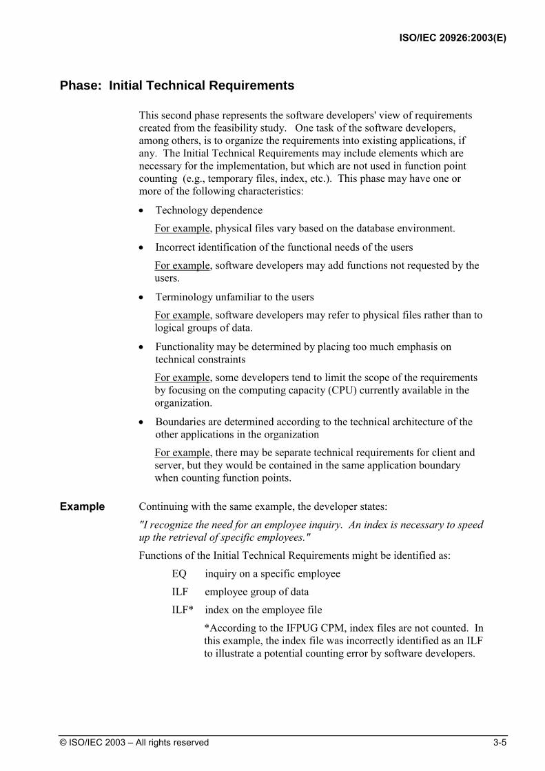
Phase: Initial Technical Requirements This second phase represents the software developers' view of requirements
created from the feasibility study. One task of the software developers, among others, is to organize the requirements into existing applications, if any. The Initial Technical Requirements may include elements which are necessary for the implementation, but which are not used in function point counting (e.g., temporary files, index, etc.). This phase may have one or more of the following characteristics:
• Technology dependence For example, physical files vary based on the database environment.
• Incorrect identification of the functional needs of the users
For example, software developers may add functions not requested by the users.
• Terminology unfamiliar to the users For example, software developers may refer to physical files rather than to logical groups of data.
• Functionality may be determined by placing too much emphasis on technical constraints
For example, some developers tend to limit the scope of the requirements by focusing on the computing capacity (CPU) currently available in the organization.
• Boundaries are determined according to the technical architecture of the other applications in the organization
For example, there may be separate technical requirements for client and server, but they would be contained in the same application boundary when counting function points.
Example Continuing with the same example, the developer states:
"I recognize the need for an employee inquiry. An index is necessary to speed up the retrieval of specific employees." Functions of the Initial Technical Requirements might be identified as:
EQ inquiry on a specific employee
ILF employee group of data
ILF* index on the employee file
*According to the IFPUG CPM, index files are not counted. In this example, the index file was incorrectly identified as an ILF to illustrate a potential counting error by software developers.

ISO/IEC 20926:2003(E)
3-6 © ISO/IEC 2003 – All rights reserved
Phase: Final Functional Requirements This third phase of requirements results from joint sessions between the
user(s) and the software developer(s). The joint sessions are necessary to achieve consistent and complete functional requirements for the application. This phase is the final version of the functional requirements before the development phase begins and has the following characteristics:
• Contains terminology which can be understood by both users and software developers
• Provides integrated descriptions of all user requirements, including requirements from different users
• Is complete and consistent enough to accurately count function points
• Each process and group of data is approved by the user
• The feasibility and usability are approved by the software developers Example Continuing with the same example:
User: "Whenever I’m working with an employee, I want to be able to view the employee's information by entering his or her name."
Developer: "I recognize the need for an employee inquiry, but many employees may have the same name. It is not possible to specify an individual employee by typing his/her name; therefore, I suggest an on-line employee list (name, location and social security number) from which to select an employee. An index will be necessary to speed up the retrieval of a specific employee."
User: "I agree that the employee selection list is necessary in this case, and it may also be used for purposes other than selecting an employee.”
Result of the discussions between the user and the developer:
• Add the on-line list of employees to the functional requirements and the function point count
• Exclude the employee index from the function point count since it is a technical solution
Functions of the Final Functional Requirements example:
EQ inquiry on a specific employee
EQ on-line list of employees
ILF employee group of data
The Final Functional Requirements document is the final version of the requirements before beginning the development phase. At this time, there should be agreement that the documented requirements are complete, formal and approved. The function point count, assuming no additional changes of scope, should be consistent with the count at the completion of development.

ISO/IEC 20926:2003(E)
© ISO/IEC 2003 – All rights reserved 3-7
Life Cycle Phase Comparisons
Prior to beginning a function point count, determine the application’s life
cycle phase and whether you are approximating or measuring. Document any assumptions.
Approximating permits assumptions about unknown functions and/or their complexity to accomplish a function point analysis.
Measuring includes the identification of all functions and their complexity to accomplish a function point analysis.
At an early stage, Initial Users Requirements could be the only document available for function point analysis. Despite the disadvantages, this count can be very useful to produce an early estimate. Uses of function point analysis for approximating at the various life cycle phases is presented below:
Life Cycle Phase Size can be approximated
Size can be measured
Proposal: users express needs and intentions yes no Requirements: developers and users review and agree upon expression of user needs and intentions
yes yes
Design: developers may include elements for implementation that are not used for function point analysis
yes yes
Construction yes yes Delivery yes yes Corrective Maintenance yes yes
Note: No specific development life cycle is implied. If using an iterative approach, you may expect to approximate for some time into the application life cycle.
Be aware and measure only new or refined agreed upon user needs and intentions.
ISO/IEC 20926:2003(E)
3-8 © ISO/IEC 2003 – All rights reserved
Hints to Help with Counting
The following hints may help identify the user view of an application and apply function point analysis.
• Do not assume that one physical file equates to one logical file when viewing data logically from the user perspective.
• Although some storage technologies, such as tables in a relational DBMS or a sequential flat file, relate closely to ILFs or EIFs, do not assume that this is always equal to a one-to-one physical-logical relationship.
• Do not assume all physical files must be counted or included as part of an ILF or EIF.
• Look at the different paper forms currently used by the user(s) when identifying transactional functions.
• A transaction which occurs in multiple physical inputs, transaction files or screens, but which has identical processing logic typically corresponds to one transactional function (EI, EO, EQ).
• Remember that one physical report, screen or batch output file can, when viewed logically, correspond to a number of EOs/EQs.
• Remember that two or more physical reports, screens or batch output files can correspond to one EO/EQ if the processing logic is identical.
• Remember that resorting or rearranging a set of data does not make processing logic unique.

ISO/IEC 20926:2003(E)
© ISO/IEC 2003 – All rights reserved 4-1
4 Determine Type of Count
IdentifyCounting Scopeand Application
Boundary
Introduction The first step of the function point counting procedure is to identify the type
of function point count.
This chapter includes a detailed explanation of the types of function point counts: development project, enhancement project, and application.
Contents This chapter includes the following sections:
Topic See Page Definitions: Types of Function Point Counts 4-2
Development Project 4-2
Enhancement Project 4-2
Application 4-2
Diagram of Types of Counts 4-3
Estimated and Final Counts 4-3
ISO/IEC 20926:2003(E)
4-2 © ISO/IEC 2003 – All rights reserved
Definitions: Types of Function Point Counts
Function point counts can be associated with either projects or applications. There are three types of function point counts:
• Development project
• Enhancement project
• Application
The following paragraphs define each type of function point count.
Note: Chapter 9 includes the formulas used to calculate the adjusted function point count for each of the three types of counts.
Development Project The development project function point count measures the functions
provided to the users with the first installation of the software delivered when the project is complete.
Enhancement Project The enhancement project function point count measures the modifications to
the existing application that add, change, or delete user functions delivered when the project is complete.
When the functionality from an enhancement project is installed, the application function point count must be updated to reflect changes in the application's functionality.
Application The application function point count and project count are associated with an
installed application. It is also referred to as the baseline or installed function point count. This count provides a measure of the current functions the application provides the user. This number is initialized when the development project function point count is completed. It is updated every time completion of an enhancement project alters the application's functions.
ISO/IEC 20926:2003(E)
© ISO/IEC 2003 – All rights reserved 4-3
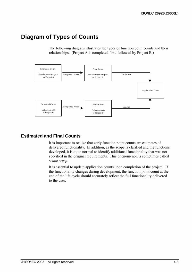
Diagram of Types of Counts
The following diagram illustrates the types of function point counts and their relationships. (Project A is completed first, followed by Project B.)
Estimated Count
Development Project as Projec t A
Final Count
Development Projectas Project A
Estimated Count
Enhancementsas Project B
Final Count
Enhancementsas Project B
Applic ation Count
Completed Projec t
Completed Projec t
Initializes
Updates
Estimated and Final Counts It is important to realize that early function point counts are estimates of
delivered functionality. In addition, as the scope is clarified and the functions developed, it is quite normal to identify additional functionality that was not specified in the original requirements. This phenomenon is sometimes called scope creep. It is essential to update application counts upon completion of the project. If the functionality changes during development, the function point count at the end of the life cycle should accurately reflect the full functionality delivered to the user.

ISO/IEC 20926:2003(E)
4-4 © ISO/IEC 2003 – All rights reserved
(Blank page)

ISO/IEC 20926:2003(E)
© ISO/IEC 2003 – All rights reserved 5-1
Determine Type of Count
5 IdentifyCounting Scope
and Application Boundary
Introduction This chapter defines the terms: purpose of the count, counting scope and
application boundary. It includes rules, procedures, and hints to determine boundaries for applications and to establish the scope of the count.
Contents This chapter includes the following sections:
Topic See Page Definition of Counting Scope and Application Boundary 5-2
Definition of the Purpose of the Count 5-2
Definition of the Counting Scope 5-2
Definition of the Application Boundary 5-3
Counting Scope and Application Boundary Rules and Procedures
5-5
Boundary Rules 5-5
Counting Scope and Application Boundary Procedures 5-5
Hints to Help to Identify the Counting Scope and the Application Boundary
5-6

ISO/IEC 20926:2003(E)
5-2 © ISO/IEC 2003 – All rights reserved
Definition of Counting Scope and Application Boundary
This section defines counting scope and application boundary and explains how they are influenced by the purpose of the count.
Definition of the Purpose of the Count The purpose of a function point count is to provide an answer to a business
problem.
The purpose:
• Determines the type of function point count and the scope of the required count to obtain the answer to the business problem under investigation
• Influences the positioning of the boundary between the software under review and the surrounding software; e.g., if the Personnel Module from the Human Resources System is to be replaced by a package, the users may decide to reposition the boundary and consider the Personnel Module as a separate application
Examples of purposes are:
• To provide a function point count as an input to the estimation process to determine the effort to develop the first release of an application
• To provide a function point count of the installed base of applications
• To provide a function point count to enable the comparison of functionality delivered by two different suppliers’ packages
Definition of the Counting Scope The counting scope defines the functionality which will be included in a
particular function point count. The scope:
• Defines a (sub) set of the software being sized • Is determined by the purpose for performing the function point count • Identifies which functions will be included in the function point count so as
to provide answers relevant to the purpose for counting • Could include more than one application

ISO/IEC 20926:2003(E)
© ISO/IEC 2003 – All rights reserved 5-3
The scope of:
• An enhancement function point count includes all the functions being added, changed and deleted. The boundary of the application(s) impacted remains the same. The functionality of the application(s) reflects the impact of the functions being added, changed or deleted.
• A development function point count includes all functions impacted (built or customized) by the project activities.
• An application function point count may include, depending on the purpose (e.g., provide a package as the software solution):
− only the functions being used by the user
− all the functions delivered
The application boundary of the two counts is the same and is independent of the scope.
ISO/IEC 20926:2003(E)
5-4 © ISO/IEC 2003 – All rights reserved
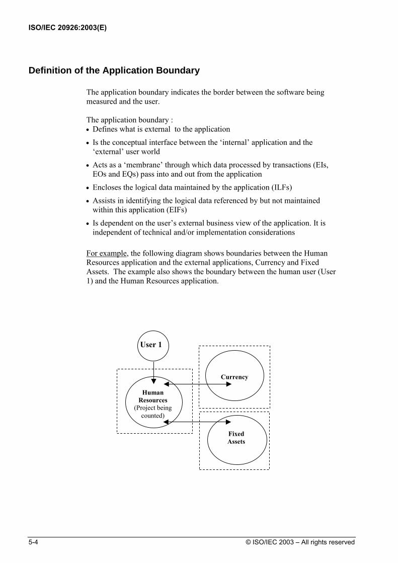
Definition of the Application Boundary The application boundary indicates the border between the software being
measured and the user. The application boundary : • Defines what is external to the application
• Is the conceptual interface between the ‘internal’ application and the ‘external’ user world
• Acts as a ‘membrane’ through which data processed by transactions (EIs, EOs and EQs) pass into and out from the application
• Encloses the logical data maintained by the application (ILFs)
• Assists in identifying the logical data referenced by but not maintained within this application (EIFs)
• Is dependent on the user’s external business view of the application. It is independent of technical and/or implementation considerations
For example, the following diagram shows boundaries between the Human
Resources application and the external applications, Currency and Fixed Assets. The example also shows the boundary between the human user (User 1) and the Human Resources application.
Human Resources
(Project being counted)
Currency
Fixed Assets
User 1

ISO/IEC 20926:2003(E)
© ISO/IEC 2003 – All rights reserved 5-5
Counting Scope and Application Boundary Rules and Procedures
This section defines the rules and procedures that apply when identifying counting scope and application boundaries.
The position of the application boundary is important because it impacts the result of the function point count. The application boundary assists in identifying the data entering the application which will be included in the scope of the count.
Boundary Rules The following rules must apply for boundaries:
The boundary is determined based on the user's view. The focus is on what the user can understand and describe.
The boundary between related applications is based on separate functional areas as seen by the user, not on technical considerations.
The initial boundary already established for the application or applications being modified is not influenced by the counting scope.
Note: There may be more than one application included in the counting scope. If so, multiple application boundaries would be identified.
When the application boundary is not well-defined (such as early in analysis), it should be located as accurately as possible.
Counting Scope and Application Boundary Procedures When you perform a function point count, the following characteristics of the
count should be properly documented:
Step Action 1 Establish the purpose of the count 2 Identify the counting scope 3 Identify the application boundary 4 Document the following items:
• The purpose of the count • The counting scope • The application boundary • Any assumptions related to the above

ISO/IEC 20926:2003(E)
5-6 © ISO/IEC 2003 – All rights reserved
Hints to Help to Identify the Counting Scope and the Application Boundary
Counting Scope
The following hints can help you to identify the counting scope:
• Review the purpose of the function point count to help determine the counting scope.
• When identifying the scope of the installed base function point count (i.e., the functionality supported by the maintenance team), include all functions currently in production and used by the users.
Application Boundary
The following hints can help you to identify the application boundary:
• Use the system external specifications or get a system flow chart and draw a boundary around it to highlight which parts are internal and which are external to the application.
• Look at how groups of data are being maintained.
• Identify functional areas by assigning ownership of certain types of analysis objects (such as entities or elementary processes) to a functional area.
• Look at associated measurement data, such as effort, cost, and defects. The boundaries for function points and the other measurement data should be the same.
Hints The positioning of the application boundary between the software under
investigation and other software applications may be subjective. It is often difficult to delineate where one application stops and another begins. Try to place the boundary from a business perspective rather than based on technical or physical considerations. It is important that the application boundary is placed with care, since all data crossing the boundary can potentially be included in the scope of the count.

ISO/IEC 20926:2003(E)
© ISO/IEC 2003 – All rights reserved 6-1
Introduction Data functions represent the functionality provided to the user to meet internal and external data requirements. Data function types are defined as internal logical files (ILFs) and external interface files (EIFs).
The term file here does not mean file in the traditional data processing sense. In this case, file refers to a logically related group of data and not the physical implementation of those groups of data.
This chapter includes the definitions for internal logical files and external interface files and explains the counting procedures and rules associated with these functions.
Contents This chapter includes the following sections:
Topic See Page Definitions: ILFs and EIFs 6-3
Internal Logical Files 6-3
External Interface Files 6-3
Difference between ILFs and EIFs 6-3
Definitions for Embedded Terms 6-3
Continued on next page
DetermineType ofCount
CountTransactional
Functions
DetermineValue
AdjustmentFactor
CountData
FunctionsIdentifyCounting Scopeand Application
Boundary
6

ISO/IEC 20926:2003(E)
6-2 © ISO/IEC 2003 – All rights reserved
Topic See Page
ILF/EIF Counting Rules 6-5
Summary of Counting Procedures 6-5
ILF Identification Rules 6-6
EIF Identification Rules 6-6
Complexity and Contribution Definitions and Rules 6-7
DET Definition 6-7
DET Rules 6-7
RET Definition 6-9
RET Rules 6-9
ILF/EIF Counting Procedures 6-10
Procedure Diagram 6-10
Identification Procedures 6-10
Complexity and Contribution Procedures 6-11
Hints to Help with Counting 6-13
ILF/EIF Counting Examples 6-14 ILF Counting Examples 6-18
EIF Counting Examples 6-58
ISO/IEC 20926:2003(E)
© ISO/IEC 2003 – All rights reserved 6-3
Definitions: ILFs and EIFs
This section includes the definitions of the internal logical files (ILFs) and external interface files (EIFs). Embedded terms within the definitions are defined and examples are included throughout this definition section.
Internal Logical Files An internal logical file (ILF) is a user identifiable group of logically related
data or control information maintained within the boundary of the application. The primary intent of an ILF is to hold data maintained through one or more elementary processes of the application being counted.
External Interface Files An external interface file (EIF) is a user identifiable group of logically related
data or control information referenced by the application, but maintained within the boundary of another application. The primary intent of an EIF is to hold data referenced through one or more elementary processes within the boundary of the application counted. This means an EIF counted for an application must be in an ILF in another application.
Difference between ILFs and EIFs The primary difference between an internal logical file and an external
interface file is that an EIF is not maintained by the application being counted, while an ILF is.
Definitions for Embedded Terms The following paragraphs further define ILFs and EIFs by defining embedded
terms within the definitions. Control Information
Control Information is data that influences an elementary process of the application being counted. It specifies what, when, or how data is to be processed.
For example, someone in the payroll department establishes payment cycles to schedule when the employees for each location are to be paid. The payment cycle, or schedule, contains timing information that affects when the elementary process of paying employees occurs.
ISO/IEC 20926:2003(E)
6-4 © ISO/IEC 2003 – All rights reserved
User Identifiable
The term user identifiable refers to defined requirements for processes and/or groups of data that are agreed upon, and understood by, both the user(s) and software developer(s).
For example, users and software developers agree that a Human Resources Application will maintain and store Employee information in the application.
Maintained The term maintained is the ability to modify data through an elementary
process.
Examples include, but are not limited to, add, change, delete, populate, revise, update, assign, and create.
Elementary Process
An elementary process is the smallest unit of activity that is meaningful to the user(s).
For example, a user requires the ability to add a new employee to the application. The user definition of employee includes salary and dependent information. From the user perspective, the smallest unit of activity is to add a new employee. Adding one of the pieces of information, such as salary or dependent, is not an activity that would qualify as an elementary process.
The elementary process must be self-contained and leave the business of the application being counted in a consistent state.
For example, the user requirements to add an employee include setting up salary and dependent information. If all the employee information is not added, an employee has not yet been created. Adding some of the information alone leaves the business of adding an employee in an inconsistent state. If both the employee salary and dependent information is added, this unit of activity is completed and the business is left in a consistent state.
ISO/IEC 20926:2003(E)
© ISO/IEC 2003 – All rights reserved 6-5
ILF/EIF Counting Rules
This section defines the rules that apply when counting internal logical files and external interface files.
Summary of Counting Procedures This summary is included to show the rules in the context of the ILF and EIF
counting procedures.
Note: The detailed counting procedures begin on page 6-10.
The ILF and EIF counting procedures include the following two activities:
Step Action 1 Identify the ILFs and EIFs.
2 Determine the ILF or EIF complexity and their contribution to the unadjusted function point count.
ILF and EIF counting rules are used for each activity. There are two types of
rules:
• Identification rules
• Complexity and contribution rules
The following list outlines how the rules are presented:
• ILF identification rules
• EIF identification rules
• Complexity and contribution rules, which include:
• Data element types (DETs)
• Record element types (RETs)

ISO/IEC 20926:2003(E)
6-6 © ISO/IEC 2003 – All rights reserved
ILF Identification Rules To identify ILFs, look for groups of data or control information that satisfy the
definition of an ILF.
All of the following counting rules must apply for the information to be counted as an ILF.
The group of data or control information is logical and user identifiable.
The group of data is maintained through an elementary process within the application boundary being counted.
EIF Identification Rules To identify EIFs, look for groups of data or control information that satisfy
the definition of an EIF.
All of the following counting rules must apply for the information to be counted as an EIF.
The group of data or control information is logical and user identifiable.
The group of data is referenced by, and external to, the application being counted.
The group of data is not maintained by the application being counted.
The group of data is maintained in an ILF of another application.

ISO/IEC 20926:2003(E)
© ISO/IEC 2003 – All rights reserved 6-7
Complexity and Contribution Definitions and Rules The number of ILFs, EIFs, and their relative functional complexity determine
the contribution of the data functions to the unadjusted function point count.
Assign each identified ILF and EIF a functional complexity based on the number of data element types (DETs) and record element types (RETs) associated with the ILF or EIF.
This section defines DETs and RETs and includes the counting rules for each. DET Definition
A data element type is a unique user recognizable, non-repeated field.
DET Rules The following rules apply when counting DETs:
Count a DET for each unique user recognizable, non-repeated field maintained in or retrieved from the ILF or EIF through the execution of an elementary process.
For example, an account number that is stored in multiple fields is counted as one DET.
For example, a before or after image for a group of 10 fields maintained for audit purposes would count as one DET for the before image (all 10 fields) and as one DET for the after image (all 10 fields) for a total of 2 DETs.
For example, the result(s) of a calculation from an elementary process, such as calculated sales tax value for a customer order maintained on an ILF is counted as one DET on the customer order ILF.
For example, accessing the price of an item which is saved to a billing file or fields such as a time stamp if required by the user(s) are counted as DETs.
For example, if an employee number which appears twice in an ILF or EIF as (1) the key of the employee record and (2) a foreign key in the dependent record, count the DET only once.
For example, within an ILF or EIF, count one DET for the 12 Monthly Budget Amount fields. Count one additional field to identify the applicable month.
When two applications maintain and/or reference the same ILF/EIF, but each maintains/references separate DETs, count only the DETs being used by each application to size the ILF/EIF.
For example, Application A may specifically identify and use an address as: street address, city, state and zip code. Application B may see the address as one block of data without regard to individual components. Application A would count four DETs; Application B would count one DET.
For example, Application X maintains and/or references an ILF that

ISO/IEC 20926:2003(E)
6-8 © ISO/IEC 2003 – All rights reserved
contains a SSN, Name, Street Name, Mail Stop, City, State, and Zip. Application Z maintains and/or references the Name, City, and State. Application X would count seven DETs; Application Z would count three DETs.
Count a DET for each piece of data required by the user to establish a relationship with another ILF or EIF.
For example, in an HR application, an employee's information is maintained on an ILF. The employee’s job name is included as part of the employee's information. This DET is counted because it is required to relate an employee to a job that exists in the organization. This type of data element is referred to as a foreign key.
For example, in an object oriented (OO) application, the user requires an association between object classes, which have been identified as separate ILFs. Location name is a DET in the Location EIF. The location name is required when processing employee information; consequently, it is also counted as a DET within the Employee ILF.

ISO/IEC 20926:2003(E)
© ISO/IEC 2003 – All rights reserved 6-9
RET Definition
A record element type (RET) is a user recognizable subgroup of data elements within an ILF or EIF.
There are two types of subgroups:
• Optional
• Mandatory
Optional subgroups are those that the user has the option of using one or none of the subgroups during an elementary process that adds or creates an instance of the data.
Mandatory subgroups are subgroups where the user must use at least one.
For example, in a Human Resources Application, information for an employee is added by entering some general information. In addition to the general information, the employee is a salaried or hourly employee.
The user has determined that an employee must be either salaried or hourly. Either type can have information about dependents. For this example, there are three subgroups or RETs as shown below:
• Salaried employee (mandatory); includes general information
• Hourly employee (mandatory); includes general information
• Dependent (optional) RET Rules One of the following rules applies when counting RETs:
Count a RET for each optional or mandatory subgroup of the ILF or EIF.
Or If there are no subgroups, count the ILF or EIF as one RET.

ISO/IEC 20926:2003(E)
6-10 © ISO/IEC 2003 – All rights reserved
ILF/EIF Counting Procedures
This section includes detailed explanations of ILF and EIF counting procedures.
Procedure Diagram The following diagram shows the high-level procedure for counting ILFs and
EIFs.
Count DataFunctions
Identify InternalLogical Files
1.0
Identify ExternalInterface Files
2.0
DetermineComplexity and
Contribution3.0
The following paragraphs explain the steps for each activity.
Identification Procedures Follow these steps to identify ILFs and EIFs:
Step Action Rule Set(s) to Use See Page 1.0 Identify Internal Logical
Files ILF Identification Rules 6-6
2.0 Identify External Interface Files
EIF Identification Rules 6-6
3.0 Determine Complexity and Contribution
Complexity and Contribution Procedures
6-11
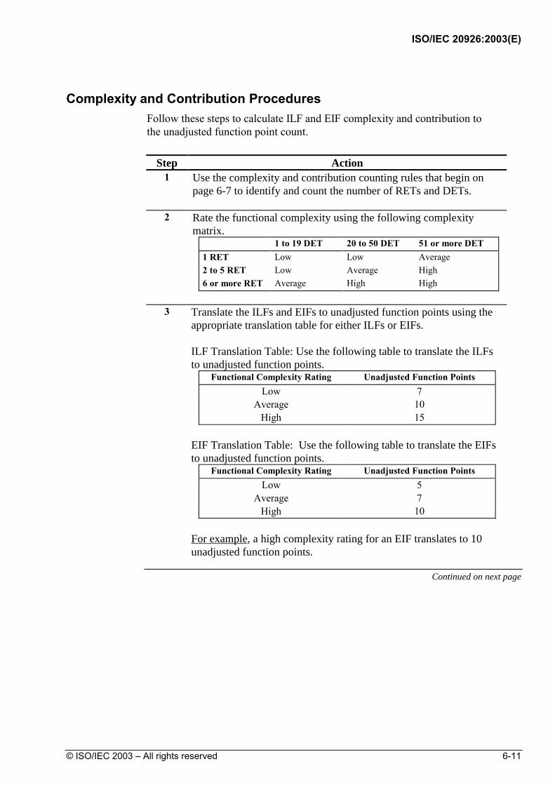
ISO/IEC 20926:2003(E)
© ISO/IEC 2003 – All rights reserved 6-11
Complexity and Contribution Procedures Follow these steps to calculate ILF and EIF complexity and contribution to
the unadjusted function point count.
Step Action 1 Use the complexity and contribution counting rules that begin on
page 6-7 to identify and count the number of RETs and DETs.
2 Rate the functional complexity using the following complexity matrix.
1 to 19 DET 20 to 50 DET 51 or more DET 1 RET Low Low Average 2 to 5 RET Low Average High 6 or more RET Average High High
3 Translate the ILFs and EIFs to unadjusted function points using the appropriate translation table for either ILFs or EIFs. ILF Translation Table: Use the following table to translate the ILFs to unadjusted function points.
Functional Complexity Rating Unadjusted Function Points Low 7 Average 10 High 15 EIF Translation Table: Use the following table to translate the EIFs
to unadjusted function points. Functional Complexity Rating Unadjusted Function Points Low 5 Average 7 High 10 For example, a high complexity rating for an EIF translates to 10
unadjusted function points.
Continued on next page

ISO/IEC 20926:2003(E)
6-12 © ISO/IEC 2003 – All rights reserved
Step Action
4 Calculate each ILF and EIF contribution to the unadjusted function point count. For example, the following table shows the calculation for one high complexity ILF, two average and one high complexity EIFs.
Function
Type Functional Complexity Complexity
Totals Function Type Totals
ILF 0 Low X 7 = 0 0 Average X 10 = 0 1 High X 15 = 15 15 EIF 0 Low X 5 = 0 2 Average X 7 = 14 _1_ High X 10 = _10__ 24 In this simple example, there are no ILFs of low or average
complexity; therefore, the total count for ILFs is 15. For the EIFs, there are no low complexity, 2 average complexity EIFs (14 points) and 1 high complexity (10 points) for an EIF total of 24. The contributions for ILFs and EIFs will be added to the table that lists all function types. The final total for all function types is the unadjusted function point count. The Appendix includes a table to record the totals for all functions.

ISO/IEC 20926:2003(E)
© ISO/IEC 2003 – All rights reserved 6-13
Hints to Help with Counting
The following hints may help you apply the ILF and EIF counting rules.
Caution: These hints are not rules and should not be used as rules.
• Is the data a logical group that supports specific user requirements?
− An application can use an ILF or EIF in multiple processes, but the ILF or EIF is counted only once.
− A logical file cannot be counted as both an ILF and EIF for the same application. If the data group satisfies both rules, count as an ILF.
− If a group of data was not counted as an ILF or EIF itself, count its data elements as DETs for the ILF or EIF, which includes that group of data.
− Do not assume that one physical file, table or object class equals one logical file when viewing data logically from the user perspective.
− Although some storage technologies such as tables in a relational DBMS or sequential flat file or object classes relate closely to ILFs or EIFs, do not assume that this always equals a one-to-one physical-logical relationship.
− Do not assume all physical files must be counted or included as part of an ILF or EIF.
• Where is data maintained? Inside or outside the application boundary?
− Look at the workflow.
− In the process functional decomposition, identify where interfaces occur with the user and other applications.
− Work through the process diagram to get hints.
− Credit ILFs maintained by more than one application to each application at the time the application is counted. Only the DETs being used by each application being counted should be used to size the ILF/EIF.
• Is the data in an ILF maintained through an elementary process of the application?
− An application can use an ILF or EIF multiple times, but you count the ILF or EIF only once.
− An elementary process can maintain more than one ILF.
− Work through the process diagram to get hints.
− Credit ILFs maintained by more than one application to each application at the time the application is counted.

ISO/IEC 20926:2003(E)
6-14 © ISO/IEC 2003 – All rights reserved
ILF/EIF Counting Examples
Introduction This section uses a Human Resources (HR) application along with a Security
application and a Mail Distribution application to illustrate procedures to identify and count data functions. In addition to this section, examples are in the Case Studies which are included in the IFPUG corresponding documentation.
Caution: The examples in this section and throughout the manual have two purposes:
1. To illustrate how the function point counting rules are applied for a given set of user requirements
2. To allow you to practice using the counting procedures
Each counter must:
• Analyze the specific user requirements that apply for each project or application being counted, and
• Count based on those requirements. Contents This section explains the organization of the examples and includes detailed
examples for counting ILFs and EIFs.
Topic See Page Organization of the Counting Examples 6-15
ILF Counting Examples 6-18
EIF Counting Examples 6-58

ISO/IEC 20926:2003(E)
© ISO/IEC 2003 – All rights reserved 6-15
Organization of the Counting Examples
This section explains how the examples are presented.
Outline of the Organization The following list outlines the sequence of information in the detailed
examples.
For each example:
1. The ILFs or EIFs are identified.
2. The RETs and DETs that contribute to the functional complexity are identified and counted.
For all the examples combined:
1. All identified items are summarized, whether or not they were counted as ILFs or EIFs.
2. The complexity and contribution to the unadjusted function point count are determined for all identified ILFs or EIFs.
Diagram of the Organization The following diagram illustrates the organization of the examples.
ExampleIdentify ILF/EIF
Count RETs/DETs
ExampleIdentify ILF/EIF
Count RETs/DETs
ExampleIdentify ILF/EIF
Count RETs/DETs SummaryAll ILFs/EIFs Identified
All RETs/DETS Counted
Complexity/Contribution
All ILFs/EIFs Identified
Count for Each Example
Each example includes the following components:
1. Basis for the count
2. Tables applying the counting rules

ISO/IEC 20926:2003(E)
6-16 © ISO/IEC 2003 – All rights reserved
Diagram of Components
The following diagram illustrates the components for each example and the flow of information.
ISO/IEC 20926:2003(E)
© ISO/IEC 2003 – All rights reserved 6-17
Basis for the Count
The basis for the count begins each example. As shown in the diagram of components, the count may be based on the following components:
• User requirements
• Data and process models
• Windows, screens, or reports
Note: All components in the diagram are not included in all examples. In some examples, the requirements stand alone as the basis for the count. Other examples include a data or process model, windows, screens, and reports.
Rules Table The analysis to identify functions is presented in a table that lists the counting
rules for the function type. The rules are applied to the components that make up the basis for the count. The analysis is explained in the table in the column "Does the Rule Apply?".
Note: If all the rules apply, the example is counted as an ILF or EIF.
The next table shows the rules and explanation for the complexity for each function type identified.
Summary of ILFs/EIFs Identified After all the rules are applied for each example, a summary section lists what
was counted and what was not counted.
Complexity and Contribution for All ILFs/EIFs The last section in the examples is the calculation of the complexity and
contribution to the unadjusted function point count.
ISO/IEC 20926:2003(E)
6-18 © ISO/IEC 2003 – All rights reserved
ILF Counting Examples
Introduction This section uses a Human Resources (HR) application to illustrate
procedures to identify and count data functions. In addition to this section, further examples are in the Case Studies which are included in the corresponding IFPUG documentation.
Contents
This section includes the following examples:
Topic See Page
Summary Descriptions of ILF Counting Examples 6-19
Example: Application Data 6-20
Example: Human Resources System Security 6-25
Example: Audit Data for Inquiries and Reports 6-33
Example: Suspended Jobs 6-34
Example: Report Definition 6-38
Example: Alternate Index 6-41
Example: Shared Application Data 6-42
Example: Different Users/Different Data Views 6-48
Summary of ILFs, RETs and DETs Counted 6-54
ILF Complexity and Contribution 6-56

ISO/IEC 20926:2003(E)
© ISO/IEC 2003 – All rights reserved 6-19
Summary Descriptions of ILF Counting Examples
The examples for ILFs are described in the following table.
Example Summary Description Page
Application Data This example requires merging groups of data to identify an ILF.
6-20
HR System Security
This example looks at security for the HR System to identify ILFs.
6-25
Audit Data This example looks at the implementation to count ILFs.
6-33
Suspended Jobs This example shows how to count suspense information that is maintained within the application boundary.
6-34
Report Definition This example shows how to count user defined report definitions maintained within an application.
6-38
Alternate Index This example moves beyond the user requirements described for the report definition example to focus on requirements for physical implementation.
6-41
Shared Application Data
This example shows how to count data that is maintained by more than one application.
6-42
Different Users/Different Data Views
This example shows that two applications can count the same file with different DETs.
6-48

ISO/IEC 20926:2003(E)
6-20 © ISO/IEC 2003 – All rights reserved
Example: Application Data
User Requirements
The user requires the ability to enter, inquire, and report on information about jobs.
Information that must be maintained together includes
• Job number • Job name • Job pay grade • Job description line number • Job description lines.
The job descriptions should be a collection of 80-character lines that describe the job.
Entity-Relationship Diagram
The following entity-relationship (E-R) diagram shows two entities that resulted from data normalization. The entities are job and job description.
JOB JOBDESCRIPTION
Legend:
Mandatory One-to-Many Relationship
Attribute Entity Type
Entity Type
Job includes
• Job number • Job name • Job pay grade.
Job description includes
• Job number • Job description line number • Job description lines.

ISO/IEC 20926:2003(E)
© ISO/IEC 2003 – All rights reserved 6-21
DB2 Structure
The following diagram shows the DB2 structure for the Human Resources Application.
EMPL
JOB_DESC
JOB_ASSGNMT
JOB
PAY_GRADE
DB2 Tables This section includes the tables for the DB2 structure for the Human
Resources Application.
EMPL Table Data Elements NAME FST_NAME MID_INT LST_NAME SSN TYPE #_DEP SUPV_CD HR_RATE US_HOURLY RATE CBU_# LOC_NAME_FK CURRENCY_LOC_FK
JOB_ASSGNMT Table Data Elements DATE PERF_RATING SALARY JOB_#_FK SSN_FK
JOB_DESC Table Data Elements LINE_# DESC_LINE JOB_#_FK
JOB Table Data Elements JOB_NAME JOB_# PAY_GRADE
LOCATION Table Data Elements LOC_NAME LOC_ADDR CITY STATE ZIP COUNTRY EMPL_SSN_FK
PAY_GRADE Table Data Elements PAY_GRADE PAY_GRADE_DESC

ISO/IEC 20926:2003(E)
6-22 © ISO/IEC 2003 – All rights reserved
Identify ILFs The E-R diagram shows two groups of information:
• Job • Job description
Determine whether each group is an ILF.
The analysis of the job group is shown in the following table.
ILF Identification Rules Does the Rule Apply?
The group of data or control information is logical and user identifiable.
No. Job must include the job description entity or table to represent the user requirement to add job information.
The group of data is maintained through an elementary process within the application boundary being counted.
Yes. The elementary process maintains job, which to the user includes both job and job description entities or tables.
Based on the analysis, job alone, without the description, is not an ILF.
Now, determine whether job description is an ILF.
ILF Identification Rules Does the Rule Apply?
The group of data or control information is logical and user identifiable.
No. Job description must include the job entity or table to represent the user requirement to add job information.
The group of data is maintained through an elementary process within the application boundary being counted.
Yes. The elementary process maintains job, which to the user includes both job and job description entities or tables.
Based on the analysis, the job description alone, without the job, is not an ILF.
From the user perspective, job and job description are used together to add job information to the HR Application. We must combine job and job description entities or tables because they must be maintained together.
There is one logical group from the user perspective. That group is job information.

ISO/IEC 20926:2003(E)
© ISO/IEC 2003 – All rights reserved 6-23
Apply the ILF counting rules to determine whether the job information is an
ILF. The following table shows the analysis.
ILF Identification Rules Does the Rule Apply?
The group of data or control information is logical and user identifiable.
Yes. Together job and job description are used to add job information into the HR System.
The group of data is maintained through an elementary process within the application boundary being counted.
Yes. The process is that of entering information about jobs.
Based on the analysis, job information is an ILF. Only one ILF is counted by
merging the information for the job and job description entities or tables. Count RETs and DETs
Count the number of data element types (DETs) and record element types (RETs).
For DETs, look at each piece of information associated with the job information ILF and determine whether the DET counting rules apply.
Job includes:
• Job number • Job name • Job pay grade.
Job description includes:
• Job number • Job description line number • Job description lines.
Note: Because job description is not an ILF by itself, its DETs are included in the total for the job information ILF.
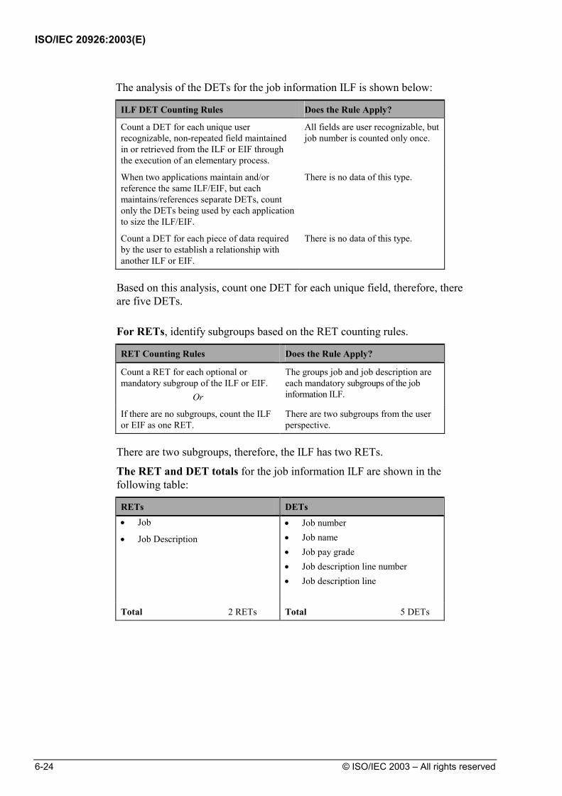
ISO/IEC 20926:2003(E)
6-24 © ISO/IEC 2003 – All rights reserved
The analysis of the DETs for the job information ILF is shown below:
ILF DET Counting Rules Does the Rule Apply?
Count a DET for each unique user recognizable, non-repeated field maintained in or retrieved from the ILF or EIF through the execution of an elementary process.
All fields are user recognizable, but job number is counted only once.
When two applications maintain and/or reference the same ILF/EIF, but each maintains/references separate DETs, count only the DETs being used by each application to size the ILF/EIF.
There is no data of this type.
Count a DET for each piece of data required by the user to establish a relationship with another ILF or EIF.
There is no data of this type.
Based on this analysis, count one DET for each unique field, therefore, there are five DETs.
For RETs, identify subgroups based on the RET counting rules.
RET Counting Rules Does the Rule Apply?
Count a RET for each optional or mandatory subgroup of the ILF or EIF.
Or
The groups job and job description are each mandatory subgroups of the job information ILF.
If there are no subgroups, count the ILF or EIF as one RET.
There are two subgroups from the user perspective.
There are two subgroups, therefore, the ILF has two RETs.
The RET and DET totals for the job information ILF are shown in the following table:
RETs DETs • Job
• Job Description
• Job number • Job name • Job pay grade • Job description line number • Job description line
Total 2 RETs Total 5 DETs
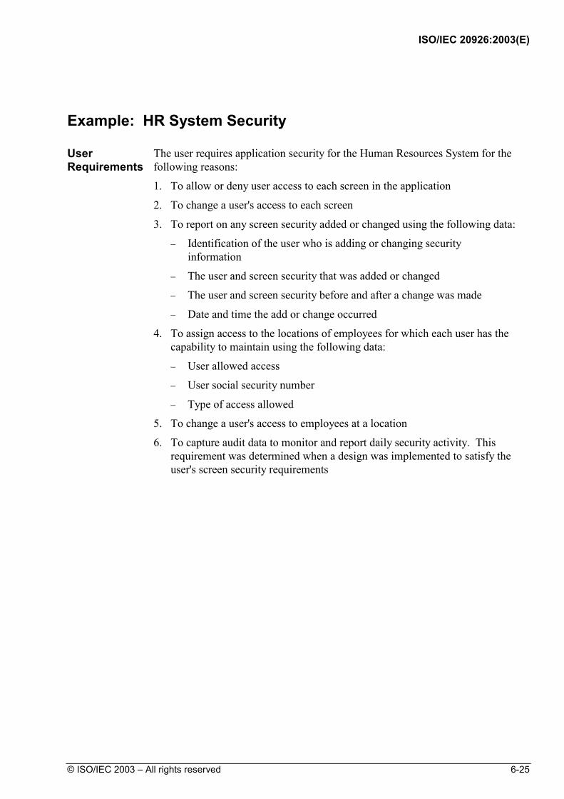
ISO/IEC 20926:2003(E)
© ISO/IEC 2003 – All rights reserved 6-25
Example: HR System Security
User Requirements
The user requires application security for the Human Resources System for the following reasons:
1. To allow or deny user access to each screen in the application
2. To change a user's access to each screen
3. To report on any screen security added or changed using the following data:
− Identification of the user who is adding or changing security information
− The user and screen security that was added or changed
− The user and screen security before and after a change was made
− Date and time the add or change occurred
4. To assign access to the locations of employees for which each user has the capability to maintain using the following data:
− User allowed access
− User social security number
− Type of access allowed
5. To change a user's access to employees at a location
6. To capture audit data to monitor and report daily security activity. This requirement was determined when a design was implemented to satisfy the user's screen security requirements

ISO/IEC 20926:2003(E)
6-26 © ISO/IEC 2003 – All rights reserved
Entity-Relationship Diagram
The following diagram shows the entity-relationship (E-R) for the Human Resources System security.
SCREENSECURITYAUDIT
SCREENSECURITY
DEPENDENT
EMPLOYEESECURITY
EMPLOYEE
SALARIED_EMPLHOURLY_EMPL
Legend:
Mandatory One-to-Many Relationship
Optional One-to-Many Relationship
Attribute Entity Type
Entity Type
Entity Subtype
Entity Attributes
The following lists show the entity attributes for the security entities from the E-R diagram for the Human Resources System.
EMPLOYEE SECURITY Data Elements User_ID Employee_Social_Security_ Number Type_Of_Access_Allowed Location
SCREEN SECURITY Data Elements User_ID Employee_Social_ Security_Number Window_ID User_Access_Allowed
SCREEN SECURITY AUDIT Data Elements Date_Time_Change_Made ID_Of_User_Making_Change User_ID_Before_Change User_Access_Before_Change Window_ID_Before_Change User_ID_After_Change User_Access_After_Change Window_ID_After_Change

ISO/IEC 20926:2003(E)
© ISO/IEC 2003 – All rights reserved 6-27
Data Flow Diagram
The following diagram shows the data flow for this example.
User
Change EmployeeSecurity
Add screen security
Request Report
access allowed,window ID
screensecurity
Change screen security
Change employee security change employee security info
Report Security
1.3
Security
1.2
1.5
EMPLOYEE
Add employee securityuser id, ss#, type access, loc
Add Screen
1.1
Security
user ID, SS#,
change
infoChange Screen
1.4
SecurityAdd Employee
ScreenSecurityScreen
ScreenSecurityScreen
Audit
Changes
SECURITY
prior, after
user id,date, time,
date, time, user id,prior, after
user id,prior, after
date, time,
Legend:
User or Application
Data Stored
Process
Flow of Data

ISO/IEC 20926:2003(E)
6-28 © ISO/IEC 2003 – All rights reserved
Identify ILFs The user requirements discuss three groups of data:
• Screen security audit
• Screen security
• Employee security
Use the ILF rules to determine if each group is an ILF.
Analyze the screen security audit.
ILF Identification Rules Does the Rule Apply?
The group of data or control information is logical and user identifiable.
No, the screen security audit data attributes are maintained only as a part of updating screen security.
The group of data is maintained through an elementary process within the application boundary being counted.
Yes, the processes are that of adding and changing window access security information.
The analysis shows that the screen security audit is not an ILF on its own.
Next, analyze the screen security together with screen security audit.
ILF Identification Rules Does the Rule Apply?
The group of data or control information is logical and user identifiable.
Yes. The user wants to control which HR information individuals may see or update. Users need to add, change, and monitor the security allowing access to windows.
The group of data is maintained through an elementary process within the application boundary being counted.
Yes. The processes are that of adding and changing window access security information and saving screen security audit data.
The analysis shows that screen security together with screen security audit
data is an ILF.

ISO/IEC 20926:2003(E)
© ISO/IEC 2003 – All rights reserved 6-29
Analyze the employee security group.
ILF Identification Rules Does the Rule Apply?
The group of data or control information is logical and user identifiable.
Yes. The user wants to limit who can maintain employee information at a specific location.
The group of data is maintained through an elementary process within the application boundary being counted.
Yes. The user wants to limit who can maintain employee information. The processes are that of adding and changing employee security information.
Based on the analysis, the employee security information is an ILF.
The analysis shows the following two ILFs:
• Screen security information
• Employee security information
Count RETs and DETs
Count the number of data element types (DETs) and record element types (RETs).
For DETs, look at each field associated with the security data and determine whether the DET counting rules apply.
• Screen security
− User ID − Employee social security number − Window ID − User access allowed
• Screen security audit
− Date Time change made − ID of user making the change − Before the change: User ID before the change User access allowed before the change Window ID before the change
− After the change: User ID after the change User access after the change Window ID after the change
• Employee security
− User ID − Employee social security number − Type of access allowed − Location
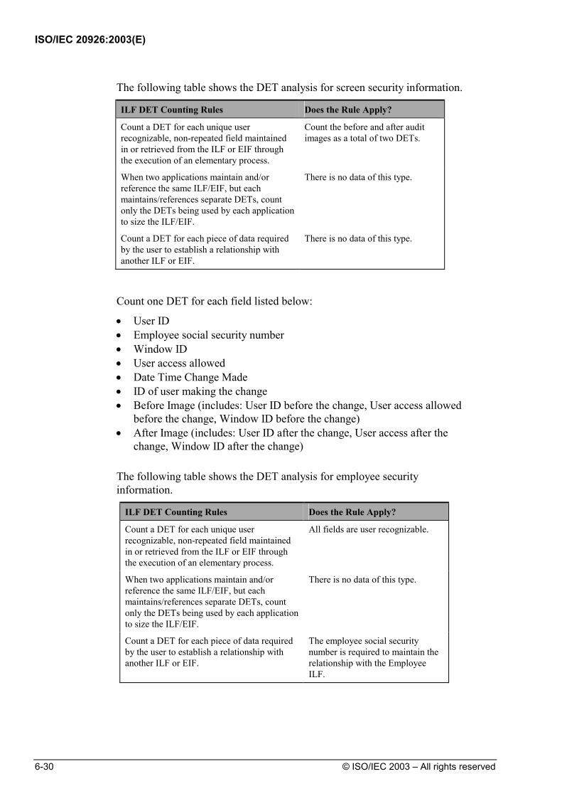
ISO/IEC 20926:2003(E)
6-30 © ISO/IEC 2003 – All rights reserved
The following table shows the DET analysis for screen security information.
ILF DET Counting Rules Does the Rule Apply?
Count a DET for each unique user recognizable, non-repeated field maintained in or retrieved from the ILF or EIF through the execution of an elementary process.
Count the before and after audit images as a total of two DETs.
When two applications maintain and/or reference the same ILF/EIF, but each maintains/references separate DETs, count only the DETs being used by each application to size the ILF/EIF.
There is no data of this type.
Count a DET for each piece of data required by the user to establish a relationship with another ILF or EIF.
There is no data of this type.
Count one DET for each field listed below:
• User ID • Employee social security number • Window ID • User access allowed • Date Time Change Made • ID of user making the change • Before Image (includes: User ID before the change, User access allowed
before the change, Window ID before the change) • After Image (includes: User ID after the change, User access after the
change, Window ID after the change) The following table shows the DET analysis for employee security
information.
ILF DET Counting Rules Does the Rule Apply?
Count a DET for each unique user recognizable, non-repeated field maintained in or retrieved from the ILF or EIF through the execution of an elementary process.
All fields are user recognizable.
When two applications maintain and/or reference the same ILF/EIF, but each maintains/references separate DETs, count only the DETs being used by each application to size the ILF/EIF.
There is no data of this type.
Count a DET for each piece of data required by the user to establish a relationship with another ILF or EIF.
The employee social security number is required to maintain the relationship with the Employee ILF.

ISO/IEC 20926:2003(E)
© ISO/IEC 2003 – All rights reserved 6-31
Count one DET for each field listed below:
• User ID • Employee social security number • Type of access allowed • Location

ISO/IEC 20926:2003(E)
6-32 © ISO/IEC 2003 – All rights reserved
For RETs, identify subgroups based on the RET counting rules. Screen Security
RET Counting Rules Does the Rule Apply?
Count a RET for each optional or mandatory subgroup of the ILF or EIF.
Or
The groups screen security and screen security audit are each mandatory subgroups of the screen security ILF.
If there are no subgroups, count the ILF or EIF as one RET.
There are two subgroups, count one RET for each.
There are two subgroups, therefore Screen Security ILF has two RETs. Employee Security
RET Counting Rules Does the Rule Apply?
Count a RET for each optional or mandatory subgroup of the ILF or EIF.
Or
There are no subgroups.
If there are no subgroups, count the ILF or EIF as one RET.
There are no subgroups..
There are no subgroups, therefore Employee Security ILF has one RET. The RET and DET totals for security are shown in the following table.
RETs DETs
• Screen security
• Screen security audit
• User ID • Employee social security number • Window ID • User access allowed • Date Time Change Made • ID of user making the change • Before Image • After Image
Total 2 RETs Total 8 DETs
• Employee security data • User ID • Employee social security number • Type of access allowed • Location
Total 1 RET Total 4 DETs
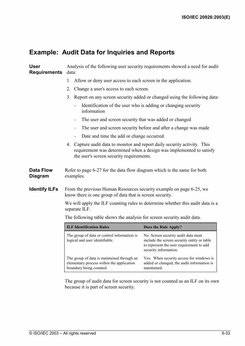
ISO/IEC 20926:2003(E)
© ISO/IEC 2003 – All rights reserved 6-33
Example: Audit Data for Inquiries and Reports
User Requirements
Analysis of the following user security requirements showed a need for audit data:
1. Allow or deny user access to each screen in the application.
2. Change a user's access to each screen.
3. Report on any screen security added or changed using the following data:
− Identification of the user who is adding or changing security information
− The user and screen security that was added or changed
− The user and screen security before and after a change was made
− Date and time the add or change occurred.
4. Capture audit data to monitor and report daily security activity. This requirement was determined when a design was implemented to satisfy the user's screen security requirements.
Data Flow Diagram
Refer to page 6-27 for the data flow diagram which is the same for both examples.
Identify ILFs From the previous Human Resources security example on page 6-25, we
know there is one group of data that is screen security.
We will apply the ILF counting rules to determine whether this audit data is a separate ILF.
The following table shows the analysis for screen security audit data.
ILF Identification Rules Does the Rule Apply?
The group of data or control information is logical and user identifiable.
No. Screen security audit data must include the screen security entity or table to represent the user requirement to add security information.
The group of data is maintained through an elementary process within the application boundary being counted.
Yes. When security access for windows is added or changed, the audit information is maintained.
The group of audit data for screen security is not counted as an ILF on its own
because it is part of screen security.
ISO/IEC 20926:2003(E)
6-34 © ISO/IEC 2003 – All rights reserved
Example: Suspended Jobs
User Requirements
The user requirements lead to a requirement for suspense files.
It was decided that adding and changing job information would be accomplished via an off-line process. During the off-line process, the user requires that the suspense file is updated with an error transaction to show any jobs not successfully updated.
The suspense file can be edited through online windows in the application to correct the transaction. Because any piece of the information about the job could be incorrect, all job and job description information is maintained when changing an incomplete or suspended job.
Note: This example examines whether the suspended job information is an ILF.

ISO/IEC 20926:2003(E)
© ISO/IEC 2003 – All rights reserved 6-35
Data Flow Diagram
The following diagram shows the data flow for this example.
suspended job
User
JOB/JOB DESC
MaintainSuspended Jobs
job_#
job_#, job_name, pay_grade, line_#, desc
job_name,pay_grade, desc job_#,
job_name, pay_grade, desc
Job and Job DescriptionReport (microfiche)
Job and Job DescriptionReport (hardcopy)
add job info
Add job transactions
Add ,Change, and Delete suspended job transactionscorrected job
Inquire Job
2.4
Report Job
2.5
Add Job in batch
2.7
2.9
job_#, job_name, pay_grade,desc, total jobs
JOB SUSPENSEChange job transactions Change Job in batch
2.8id, job_name, job_#, pay_grade,
Legend:
User or Application
Data Stored
Process
Flow of Data
Identify ILFs Determine whether the suspense information is an ILF.
The following table shows the summary analysis.
ILF Identification Rules Does the Rule Apply?
The group of data or control information is logical and user identifiable.
Yes. Jobs with incorrect information must be corrected to add to the HR application.
The group of data is maintained through an elementary process within the application boundary being counted.
Yes. The suspense information is modified through a window in the Human Resources application.
The analysis shows that error suspense information is an ILF.
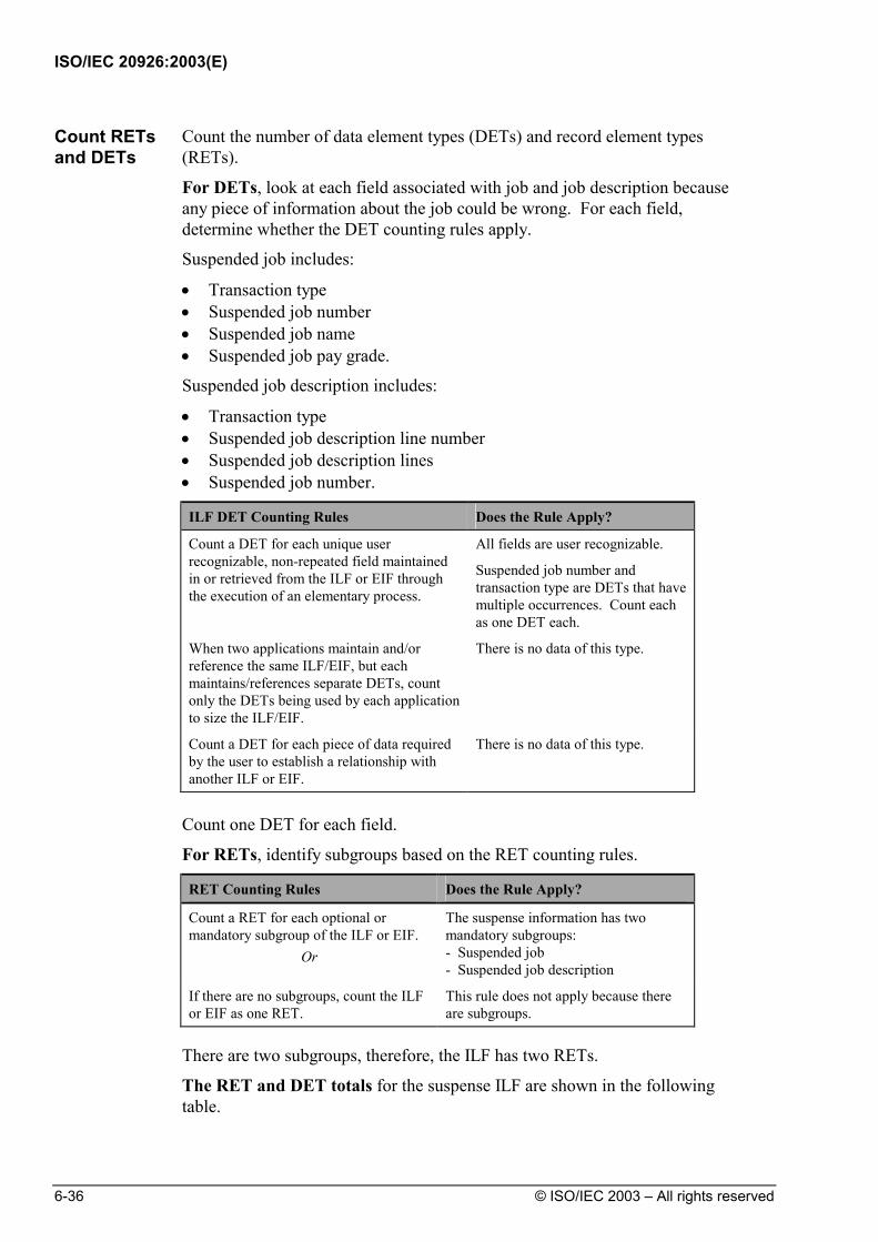
ISO/IEC 20926:2003(E)
6-36 © ISO/IEC 2003 – All rights reserved
Count RETs and DETs
Count the number of data element types (DETs) and record element types (RETs).
For DETs, look at each field associated with job and job description because any piece of information about the job could be wrong. For each field, determine whether the DET counting rules apply.
Suspended job includes:
• Transaction type • Suspended job number • Suspended job name • Suspended job pay grade.
Suspended job description includes:
• Transaction type • Suspended job description line number • Suspended job description lines • Suspended job number.
ILF DET Counting Rules Does the Rule Apply?
Count a DET for each unique user recognizable, non-repeated field maintained in or retrieved from the ILF or EIF through the execution of an elementary process.
All fields are user recognizable.
Suspended job number and transaction type are DETs that have multiple occurrences. Count each as one DET each.
When two applications maintain and/or reference the same ILF/EIF, but each maintains/references separate DETs, count only the DETs being used by each application to size the ILF/EIF.
There is no data of this type.
Count a DET for each piece of data required by the user to establish a relationship with another ILF or EIF.
There is no data of this type.
Count one DET for each field.
For RETs, identify subgroups based on the RET counting rules.
RET Counting Rules Does the Rule Apply?
Count a RET for each optional or mandatory subgroup of the ILF or EIF.
Or
The suspense information has two mandatory subgroups: - Suspended job - Suspended job description
If there are no subgroups, count the ILF or EIF as one RET.
This rule does not apply because there are subgroups.
There are two subgroups, therefore, the ILF has two RETs.
The RET and DET totals for the suspense ILF are shown in the following table.

ISO/IEC 20926:2003(E)
© ISO/IEC 2003 – All rights reserved 6-37
RETs DETs
• Suspended job • Suspended job description
• Suspended job number • Suspended job name • Suspended job pay grade • Suspended job description line
number • Suspended job description • Transaction type
Total 2 RETs Total 6 DETs

ISO/IEC 20926:2003(E)
6-38 © ISO/IEC 2003 – All rights reserved
Example: Report Definition
User Requirements
The user requires the ability to perform the following activities:
1. Enter a report definition which includes
− A unique report identifier − A report name − Fields used on the report − Calculations to generate the report.
2. Reuse the defined report at any time, changing the definition if necessary.
3. View and print a report using the report definition.
4. Inquire on existing report definitions by report name or report identifier. Identify ILFs From the user requirements, report identifier, report name, fields on the
report, and calculations together make up one logical grouping of data for a report definition because they are maintained as a group.
The following table shows the analysis to determine whether the report definition information is an ILF. See the Case Studies for how the remaining requirements may be counted.
ILF Identification Rules Does the Rule Apply?
The group of data or control information is logical and user identifiable.
Yes. The data is used to view and report information in the HR application.
The group of data is maintained through an elementary process within the application boundary being counted.
Yes. The processes are that of adding and changing the definition.
Based on the analysis, the report definition information is an ILF.
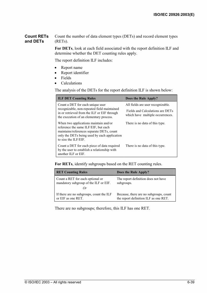
ISO/IEC 20926:2003(E)
© ISO/IEC 2003 – All rights reserved 6-39
Count RETs and DETs
Count the number of data element types (DETs) and record element types (RETs).
For DETs, look at each field associated with the report definition ILF and determine whether the DET counting rules apply.
The report definition ILF includes:
• Report name • Report identifier • Fields • Calculations
The analysis of the DETs for the report definition ILF is shown below:
ILF DET Counting Rules Does the Rule Apply?
Count a DET for each unique user recognizable, non-repeated field maintained in or retrieved from the ILF or EIF through the execution of an elementary process.
All fields are user recognizable.
Fields and Calculations are DETs which have multiple occurrences.
When two applications maintain and/or reference the same ILF/EIF, but each maintains/references separate DETs, count only the DETs being used by each application to size the ILF/EIF.
There is no data of this type.
Count a DET for each piece of data required by the user to establish a relationship with another ILF or EIF.
There is no data of this type.
For RETs, identify subgroups based on the RET counting rules.
RET Counting Rules Does the Rule Apply?
Count a RET for each optional or mandatory subgroup of the ILF or EIF.
Or
The report definition does not have subgroups.
If there are no subgroups, count the ILF or EIF as one RET.
Because, there are no subgroups, count the report definition ILF as one RET.
There are no subgroups; therefore, this ILF has one RET.
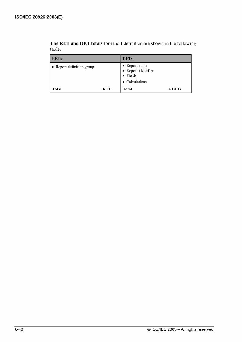
ISO/IEC 20926:2003(E)
6-40 © ISO/IEC 2003 – All rights reserved
The RET and DET totals for report definition are shown in the following
table.
RETs DETs
• Report definition group • Report name • Report identifier • Fields • Calculations
Total 1 RET Total 4 DETs

ISO/IEC 20926:2003(E)
© ISO/IEC 2003 – All rights reserved 6-41
Example: Alternate Index
User Requirements
The user needs to inquire on report definitions using the report name as the key to finding the desired definition. To satisfy the user requirement, an alternate index is created using the report name as the key.
Identify ILFs The following table shows the summary analysis to determine whether the
alternate index is an ILF.
ILF Identification Rules Does the Rule Apply?
The group of data or control information is logical and user identifiable.
No. From the user perspective, this filter function provides the user with specific attributes of the report definitions created that reference the report definition ILF. This technical filter, necessary to create the inquiry list, does not constitute a business function on its own.
The group of data is maintained through an elementary process within the application boundary being counted.
Not applicable.
Based on the analysis in the table, the alternate index is not a logical group,
therefore, it is not counted as an ILF.

ISO/IEC 20926:2003(E)
6-42 © ISO/IEC 2003 – All rights reserved
Example: Shared Application Data
User Requirements
The HR user requires the ability to maintain information on each new employee.
The information that must be maintained by the HR user includes:
• Employee ID • Employee Name • Employee Mailing Address • Employee Pay Grade • Employee Job Title
As a result of creating a new employee record, the employee’s anticipated Pension Eligibility Date should be automatically calculated and saved with the other employee information.
The Security user requires that a security level be assigned to each new employee. The Security department conducts a background search after each employee is hired and assigns the appropriated security level.
The information that must be maintained by the Security user includes:
• Employee ID • Employee Security Level
The Security user also requires a report listing the following information:
• Count of Employee IDs
• Employee Name
• Employee Security Level

ISO/IEC 20926:2003(E)
© ISO/IEC 2003 – All rights reserved 6-43
Data Flow Diagram
The following diagram shows the data flow for this example.
User
EmployeeCreateEmployee
AssignSecurity Level
HR Application Security Application
Emp_IdEmp_NameMailing AddressPay_GradeJob_TitlePension_Elig_DateSecurity_Level
Emp_IdSecurity_Level
User
Print EmployeeListing
Emp_IdEmp_NameSecurity_Level
Emp_IdEmp_NameMailing AddressPay_GradeJob_TitlePension_Elig_Date
Legend:
User or Application
Data Stored
Process
Flow of Data Identify ILFs Determine whether the employee information is an ILF for the HR
application.
The following table shows the summary analysis.
ILF Identification Rules Does the Rule Apply?
The group of data or control information is logical and user identifiable.
Yes. This information is recognized and required by the HR users.
The group of data is maintained through an elementary process within the application boundary being counted.
Yes. The process of creating an employee record is within the boundary of the HR application.
The analysis shows that the employee information is an ILF for the HR
application.

ISO/IEC 20926:2003(E)
6-44 © ISO/IEC 2003 – All rights reserved
Determine whether the employee information is an ILF for the Security
application.
The following table shows the summary analysis.
ILF Identification Rules Does the Rule Apply?
The group of data or control information is logical and user identifiable.
Yes. This information is recognized and required by the Security users.
The group of data is maintained through an elementary process within the application boundary being counted.
Yes. The process of assigning the employee security level is within the boundary of the Security application.
The analysis shows that the employee information is an ILF for the Security
application. Count RETs and DETs (HR Application)
Count the number of data element types (DETs) and record element types (RETs) for the employee ILF in the HR application.
For DETs, look at each field associated with the employee ILF in the HR application and determine whether the DET counting rules apply.
The following list includes the fields for the employee information:
• Employee ID • Employee Name • Employee Mailing Address • Employee Pay Grade • Employee Job Title • Pension Eligibility Date • Employee Security Level
The analysis of the DETs for the employee ILF in the HR application is shown below:

ISO/IEC 20926:2003(E)
© ISO/IEC 2003 – All rights reserved 6-45
ILF DET Counting Rules Does the Rule Apply?
Count a DET for each unique user recognizable, non-repeated field maintained in or retrieved from the ILF or EIF through the execution of an elementary process.
The following fields are recognized by the HR user: • Employee ID • Employee Name • Employee Mailing Address • Employee Pay Grade • Employee Job Title • Pension Eligibility Date
When two applications maintain and/or reference the same ILF/EIF, but each maintains/references separate DETs, count only the DETs being used by each application to size the ILF/EIF.
There is data of this type. All of the fields are used within the HR application except the Employee Security Level.
Count a DET for each piece of data required by the user to establish a relationship with another ILF or EIF.
There is no data of this type.
For RETs, identify subgroups based on the RET counting rules.
RET Counting Rules Does the Rule Apply?
Count a RET for each optional or mandatory subgroup of the ILF or EIF.
Or
The employee information does not have subgroups.
If there are no subgroups, count the ILF or EIF as one RET.
Because there are no subgroups, count the employee ILF in the HR application as one RET.
There are no subgroups, therefore count one RET for the employee ILF in the
HR application. The RET and DET totals for the employee ILF in the HR application are
shown in the following table.
RETs DETs
• Employee information group • Employee ID • Employee Name • Employee Mailing Address • Employee Pay Grade • Employee Job Title • Anticipated Pension Eligibility Date
Total 1 RET Total 6 DETs
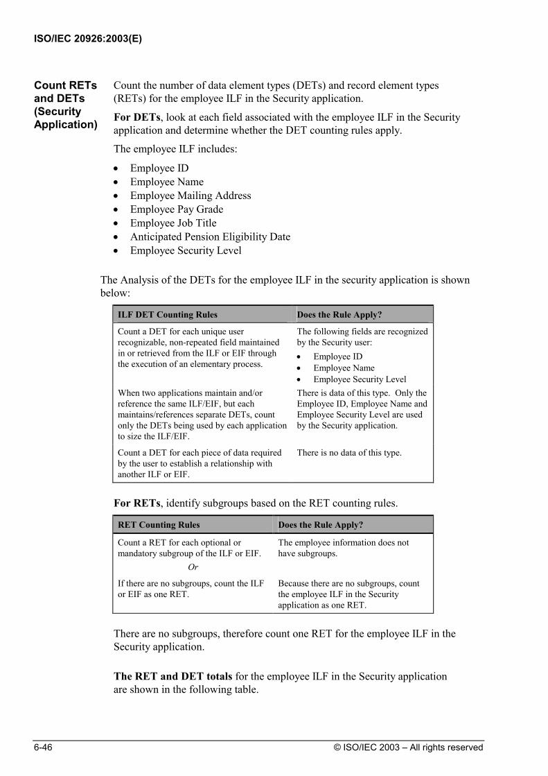
ISO/IEC 20926:2003(E)
6-46 © ISO/IEC 2003 – All rights reserved
Count RETs and DETs (Security Application)
Count the number of data element types (DETs) and record element types (RETs) for the employee ILF in the Security application.
For DETs, look at each field associated with the employee ILF in the Security application and determine whether the DET counting rules apply.
The employee ILF includes:
• Employee ID • Employee Name • Employee Mailing Address • Employee Pay Grade • Employee Job Title • Anticipated Pension Eligibility Date • Employee Security Level
The Analysis of the DETs for the employee ILF in the security application is shown below:
ILF DET Counting Rules Does the Rule Apply?
Count a DET for each unique user recognizable, non-repeated field maintained in or retrieved from the ILF or EIF through the execution of an elementary process.
The following fields are recognized by the Security user: • Employee ID • Employee Name • Employee Security Level
When two applications maintain and/or reference the same ILF/EIF, but each maintains/references separate DETs, count only the DETs being used by each application to size the ILF/EIF.
There is data of this type. Only the Employee ID, Employee Name and Employee Security Level are used by the Security application.
Count a DET for each piece of data required by the user to establish a relationship with another ILF or EIF.
There is no data of this type.
For RETs, identify subgroups based on the RET counting rules.
RET Counting Rules Does the Rule Apply?
Count a RET for each optional or mandatory subgroup of the ILF or EIF.
Or
The employee information does not have subgroups.
If there are no subgroups, count the ILF or EIF as one RET.
Because there are no subgroups, count the employee ILF in the Security application as one RET.
There are no subgroups, therefore count one RET for the employee ILF in the
Security application. The RET and DET totals for the employee ILF in the Security application
are shown in the following table.

ISO/IEC 20926:2003(E)
© ISO/IEC 2003 – All rights reserved 6-47
RETs DETs
• Employee information group • Employee ID • Employee Name • Employee Security Level
Total 1 RET Total 3 DETs

ISO/IEC 20926:2003(E)
6-48 © ISO/IEC 2003 – All rights reserved
Example: Different Users/Different Data Views
User Requirements
The information that must be maintained by the HR user includes:
• Employee ID • Employee Name • Employee Mailing Address
The Employee Mailing Address includes the following components: • Floor • Building Code • Street • City • State • Zip Code
• Employee Pay Grade • Employee Job Title
As a result of creating a new employee record, the employee’s anticipated Pension Eligibility Date should be automatically calculated and saved with the other employee information. The HR user requires the ability to produce mailing labels for each employee.
The Mail Distribution user requires the ability to maintain the Building Codes for each employee to reflect changes in the recognized codes.
The Mail Distribution user also requires the ability to evaluate the population in each site to determine the most efficient process for delivering the internal mail. A report is produced listing the number of employees located on each floor for each building.
The information that must be maintained or referenced by the Mail Distribution user includes:
• Employee ID • Floor • Building Code

ISO/IEC 20926:2003(E)
© ISO/IEC 2003 – All rights reserved 6-49
Data Flow Diagram
The following diagram shows the data flow for this example.
EmployeeCreateEmployee
HR ApplicationMail Distribution
Application
Emp_IdEmp_NameMailing Address
FloorBuilding CodeStreetCityStateZip Code
Pay_GradeJob_TitlePension_Elig_DateSecurity_Level
User
Print PopulationReport
Emp_IdEmp_NameMailing AddressPay_GradeJob_TitlePension_Elig_Date
Emp_IdFloorBuilding Code
User
MaintainBuilding Codes
Emp_IdFloorBuilding Code
Legend:
User or Application
Data Stored
Process
Flow of Data Identify ILFs Determine whether the employee information is an ILF for the HR
application.
The following table shows the summary analysis.
ILF Identification Rules Does the Rule Apply?
The group of data or control information is logical and user identifiable.
Yes. This information is recognized and required by the HR users.
The group of data is maintained through an elementary process within the application boundary being counted.
Yes. The process of creating an employee record is within the boundary of the HR application.
The analysis shows that the employee information is an ILF for the HR
application.

ISO/IEC 20926:2003(E)
6-50 © ISO/IEC 2003 – All rights reserved
Determine whether the employee information is an ILF for the Mail
Distribution application. The following table shows the summary analysis.
ILF Identification Rules Does the Rule Apply?
The group of data or control information is logical and user identifiable.
Yes. This information is recognized and required by the Mail Distribution users.
The group of data is maintained through an elementary process within the application boundary being counted.
Yes. The process of maintaining building codes is within the boundary of the Mail Distribution application.
The analysis shows that the employee information is an ILF for the Mail
Distribution application. Count RETs and DETs for HR Application
Count the number of data element types (DETs) and record element types (RETs) for the employee ILF in the HR application.
For DETs, look at each field associated with the employee ILF in the HR application and determine whether the DET counting rules apply.
Employee information includes:
• Employee ID • Employee Name • Employee Mailing Address
• Floor • Building Code • Street • City • State • Zip Code
• Employee Pay Grade • Employee Job Title • Pension Eligibility Date • Employee Security Level

ISO/IEC 20926:2003(E)
© ISO/IEC 2003 – All rights reserved 6-51
The analysis of the DETs for the employee ILF is shown below:
ILF DET Counting Rules Does the Rule Apply?
Count a DET for each unique user recognizable, non-repeated field maintained in or retrieved from the ILF or EIF through the execution of an elementary process.
The following fields are recognized by the HR user: • Employee ID • Employee Name • Employee Mailing Address • Employee Pay Grade • Employee Job Title • Pension Eligibility Date
When two applications maintain and/or reference the same ILF/EIF, but each maintains/references separate DETs, count only the DETs being used by each application to size the ILF/EIF.
There is data of this type. Only the Employee ID, Employee Name, Employee Mailing Address, Employee Pay Grade, Employee Job Title, and Pension Eligibility Date are used by the HR application.
Count a DET for each piece of data required by the user to establish a relationship with another ILF or EIF.
There is no data of this type.
For RETs, identify subgroups based on the RET counting rules.
RET Counting Rules Does the Rule Apply?
Count a RET for each optional or mandatory subgroup of the ILF or EIF.
Or
The employee information does not have subgroups.
If there are no subgroups, count the ILF or EIF as one RET.
Because, there are no subgroups, count the employee ILF in the HR application as one RET.
There are no subgroups, therefore count one RET for the employee ILF in the
HR application. The RET and DET totals for the employee ILF in the HR application are
shown in the following table.
RETs DETs
• Employee information group • Employee ID • Employee Name • Employee Mailing Address • Employee Pay Grade • Employee Job Title • Pension Eligibility Date
Total 1 RET Total 6 DETs
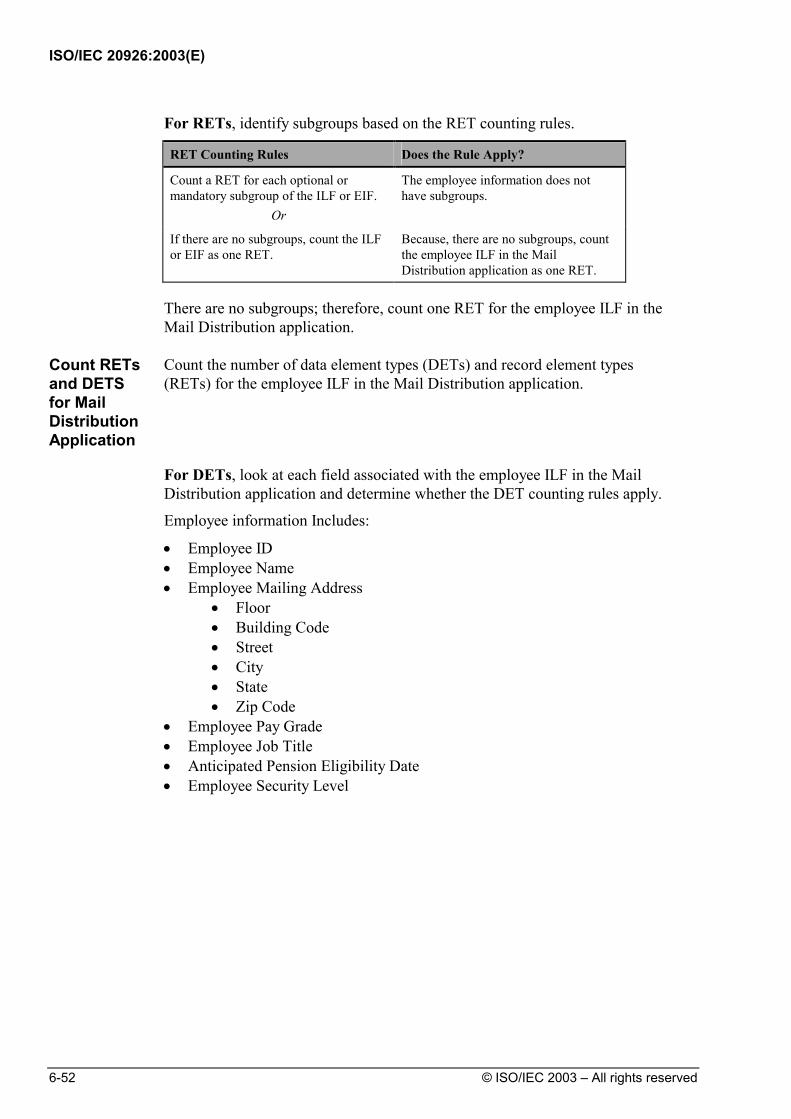
ISO/IEC 20926:2003(E)
6-52 © ISO/IEC 2003 – All rights reserved
For RETs, identify subgroups based on the RET counting rules.
RET Counting Rules Does the Rule Apply?
Count a RET for each optional or mandatory subgroup of the ILF or EIF.
Or
The employee information does not have subgroups.
If there are no subgroups, count the ILF or EIF as one RET.
Because, there are no subgroups, count the employee ILF in the Mail Distribution application as one RET.
There are no subgroups; therefore, count one RET for the employee ILF in the
Mail Distribution application.
Count RETs and DETS for Mail Distribution Application
Count the number of data element types (DETs) and record element types (RETs) for the employee ILF in the Mail Distribution application.
For DETs, look at each field associated with the employee ILF in the Mail
Distribution application and determine whether the DET counting rules apply.
Employee information Includes:
• Employee ID • Employee Name • Employee Mailing Address
• Floor • Building Code • Street • City • State • Zip Code
• Employee Pay Grade • Employee Job Title • Anticipated Pension Eligibility Date • Employee Security Level

ISO/IEC 20926:2003(E)
© ISO/IEC 2003 – All rights reserved 6-53
The analysis of the DETs for the employee information in the Mail Distribution application is shown below:
ILF DET Counting Rules Does the Rule Apply?
Count a DET for each unique user recognizable, non-repeated field maintained in or retrieved from the ILF or EIF through the execution of an elementary process.
The following fields are recognized by the Mail Distribution user: • Employee ID • Floor • Building Code
When two applications maintain and/or reference the same ILF/EIF, but each maintains/references separate DETs, count only the DETs being used by each application to size the ILF/EIF.
There is data of this type. Only the Employee ID, Floor, and Building Code are used by the Mail Distribution application.
Count a DET for each piece of data required by the user to establish a relationship with another ILF or EIF.
There is no data of this type.
The RET and DET totals for the employee ILF in the Mail Distribution
application are shown in the following table.
RETs DETs
• Employee information group • Employee ID
• Floor
• Building Code Total 1 RET Total 3 DETs
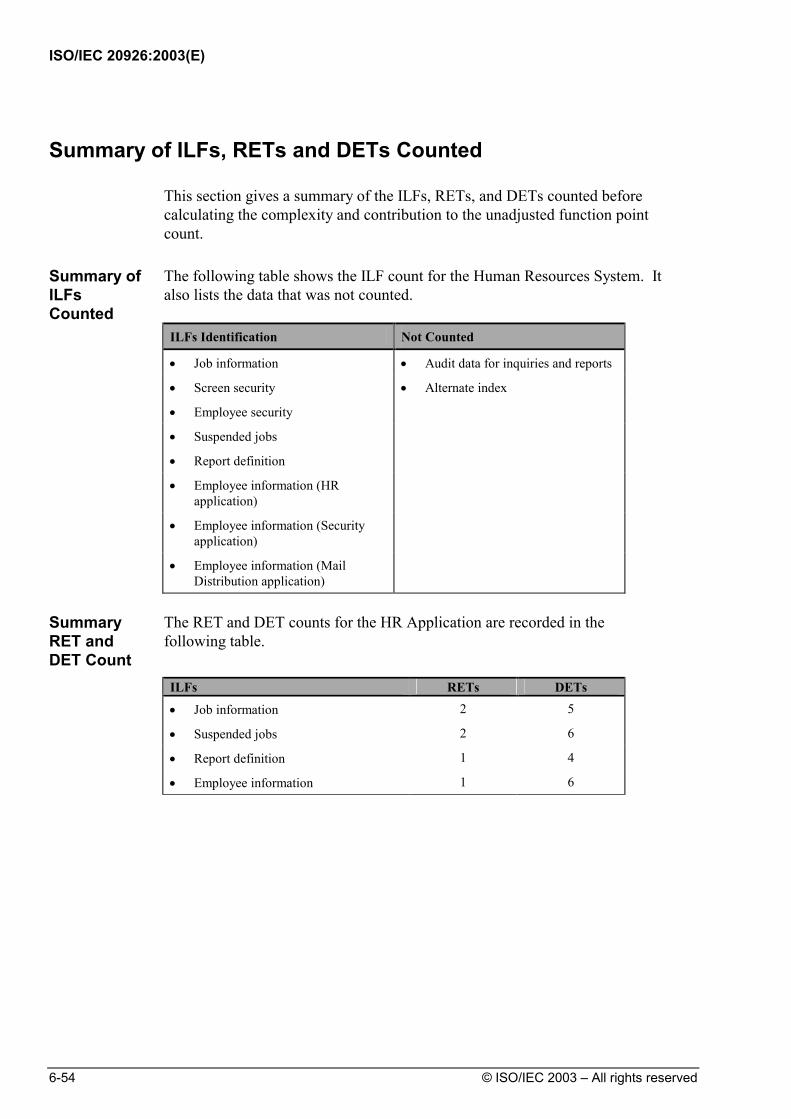
ISO/IEC 20926:2003(E)
6-54 © ISO/IEC 2003 – All rights reserved
Summary of ILFs, RETs and DETs Counted
This section gives a summary of the ILFs, RETs, and DETs counted before calculating the complexity and contribution to the unadjusted function point count.
Summary of ILFs Counted
The following table shows the ILF count for the Human Resources System. It also lists the data that was not counted.
ILFs Identification Not Counted
• Job information • Audit data for inquiries and reports
• Screen security • Alternate index
• Employee security
• Suspended jobs
• Report definition
• Employee information (HR application)
• Employee information (Security application)
• Employee information (Mail Distribution application)
Summary RET and DET Count
The RET and DET counts for the HR Application are recorded in the following table.
ILFs RETs DETs
• Job information 2 5
• Suspended jobs 2 6
• Report definition 1 4
• Employee information 1 6
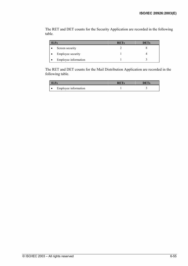
ISO/IEC 20926:2003(E)
© ISO/IEC 2003 – All rights reserved 6-55
The RET and DET counts for the Security Application are recorded in the following table.
ILFs RETs DETs
• Screen security 2 8
• Employee security 1 4
• Employee information 1 3
The RET and DET counts for the Mail Distribution Application are recorded in the following table.
ILFs RETs DETs
• Employee information 1 3

ISO/IEC 20926:2003(E)
6-56 © ISO/IEC 2003 – All rights reserved
ILF Complexity and Contribution
The last section of the ILF examples shows the final steps to determine ILF complexity and contribution to the unadjusted function point count.
The final steps are as follows:
1. Rate the ILF complexity.
2. Translate the complexity to unadjusted function points.
3. Calculate the internal logical files' contribution to the total unadjusted function point count.
Rate ILF Complexity
The functional complexity is rated as low, average, or high. The following ILF complexity matrix is used to rate the ILF complexity.
1 to 19 DETs 20 to 50 DETs 51 or more DETs
1 RET Low Low Average
2 to 5 RETs Low Average High
6 or more RETs Average High High
The following table shows the functional complexity for each HR Application
ILF. The same process would be applied to the Security and Mail Distribution data function types to determine complexity.
ILFs
RETs
DETs
Functional Complexity
1. Job information 2 5 Low
2. Suspended jobs 2 6 Low
3. Report definition 1 4 Low
4. Employee information 1 6 Low
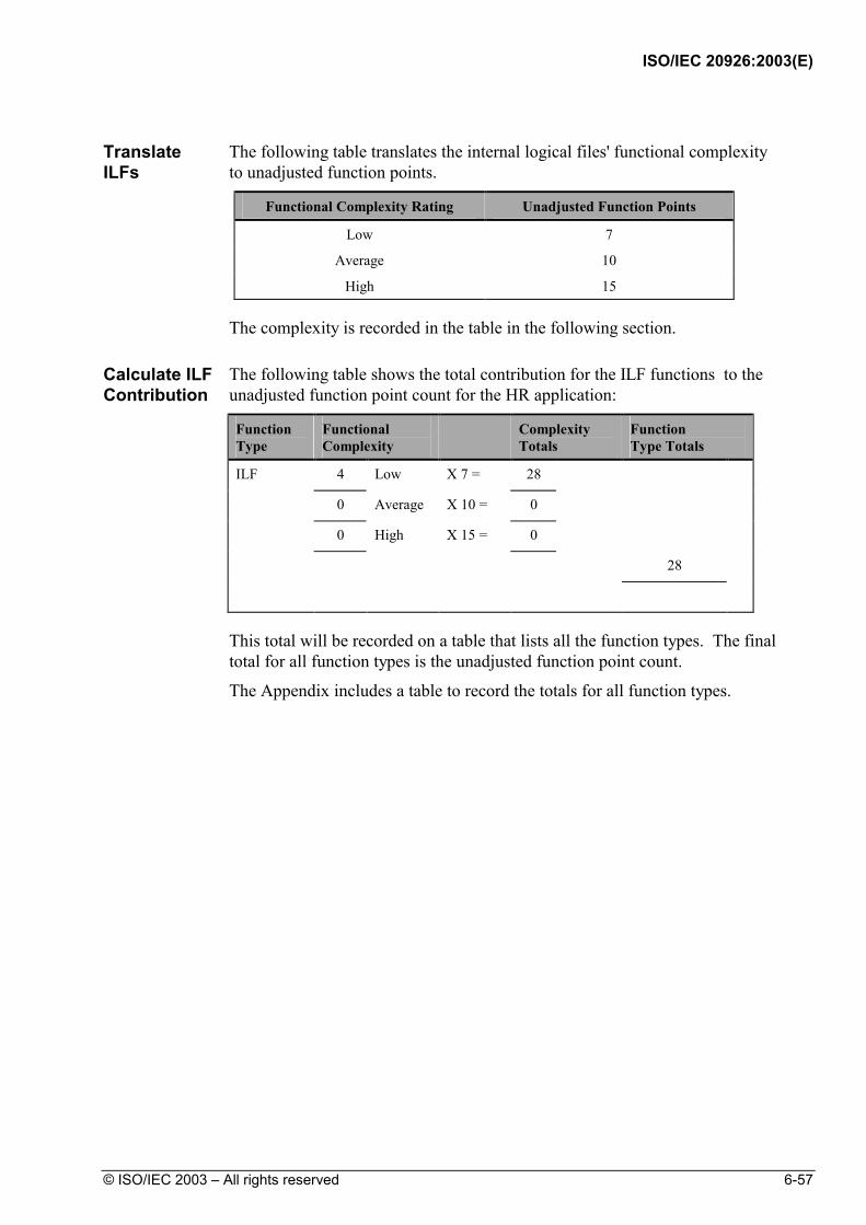
ISO/IEC 20926:2003(E)
© ISO/IEC 2003 – All rights reserved 6-57
Translate ILFs
The following table translates the internal logical files' functional complexity to unadjusted function points.
Functional Complexity Rating Unadjusted Function Points
Low 7
Average 10
High 15 The complexity is recorded in the table in the following section. Calculate ILF Contribution
The following table shows the total contribution for the ILF functions to the unadjusted function point count for the HR application:
Function Type
Functional Complexity
Complexity Totals
Function Type Totals
ILF 4 Low X 7 = 28 0 Average X 10 = 0 0 High X 15 = 0 28
This total will be recorded on a table that lists all the function types. The final
total for all function types is the unadjusted function point count.
The Appendix includes a table to record the totals for all function types.

ISO/IEC 20926:2003(E)
6-58 © ISO/IEC 2003 – All rights reserved
EIF Counting Examples Introduction This section uses a Human Resources (HR) application along with a Security
application and a Pension system to illustrate procedures used to count data functions. In addition to this section, further examples are in the Case Studies included in the corresponding IFPUG documentation.
Contents This section includes the following examples:
Topic See Page Summary Descriptions of EIF Examples 6-59
Example: Referencing Data from Other Applications 6-60
Example: Referencing Data from Another Application 6-63
Example: Providing Data to Other Applications 6-66
Example: Help Application 6-67
Example: Data Conversion 6-73
Example: Transaction Input File 6-75
Example: Different Users/Different Users View 6-77
Example: Multiple Data Uses 6-80
Summary of EIFs, RETs and DETs Counted 6-82
EIF Complexity and Contribution 6-83

ISO/IEC 20926:2003(E)
© ISO/IEC 2003 – All rights reserved 6-59
Summary Descriptions of EIF Examples
The examples for EIFs are described in the following table.
Example Summary Description Page
Referencing Data from Other Applications to generate output
This example identifies EIFs for an application that references data maintained by another application. The data is used to generate an external output.
6-60
Referencing Data from Another Application to use as part of an input process
This example also looks at referencing data from another application. This example identifies EIFs for an application that references data maintained by another application to use for an external input.
6-63
Providing Data to Other Applications
This example shows how you count when other applications retrieve a logical group of data from the application being counted.
6-66
Help Application This example shows how the HR application counts a Help facility provided by a separate application.
6-67
Data Conversion This section shows an example of counting when converting to a new application.
6-73
Transaction Input File This example applies EIF counting rules to a transaction input file processed to add jobs to the Human Resources application.
6-75
Different Users/Different User View
This example shows how the view differs when an EIF is used by multiple applications.
6-77
Multiple Data Uses This example shows multiple uses for the same data.
6-80
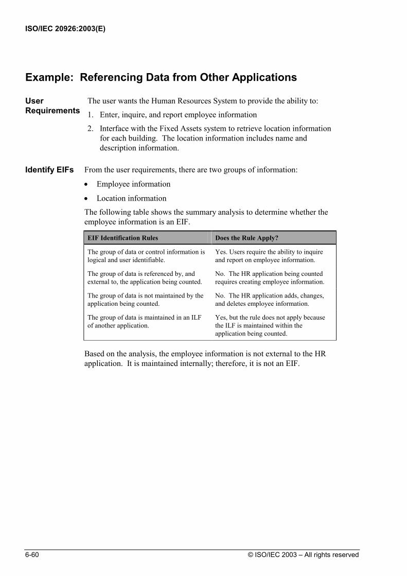
ISO/IEC 20926:2003(E)
6-60 © ISO/IEC 2003 – All rights reserved
Example: Referencing Data from Other Applications
User Requirements
The user wants the Human Resources System to provide the ability to:
1. Enter, inquire, and report employee information
2. Interface with the Fixed Assets system to retrieve location information for each building. The location information includes name and description information.
Identify EIFs From the user requirements, there are two groups of information:
• Employee information
• Location information
The following table shows the summary analysis to determine whether the employee information is an EIF.
EIF Identification Rules Does the Rule Apply?
The group of data or control information is logical and user identifiable.
Yes. Users require the ability to inquire and report on employee information.
The group of data is referenced by, and external to, the application being counted.
No. The HR application being counted requires creating employee information.
The group of data is not maintained by the application being counted.
No. The HR application adds, changes, and deletes employee information.
The group of data is maintained in an ILF of another application.
Yes, but the rule does not apply because the ILF is maintained within the application being counted.
Based on the analysis, the employee information is not external to the HR
application. It is maintained internally; therefore, it is not an EIF.
ISO/IEC 20926:2003(E)
© ISO/IEC 2003 – All rights reserved 6-61
The following table shows the analysis to determine whether the location
information is an EIF.
EIF Identification Rules Does the Rule Apply?
The group of data or control information is logical and user identifiable.
Yes. Users require the ability to retrieve the information for employee reporting.
The group of data is referenced by, and external to, the application being counted.
Yes. It is maintained externally by the Fixed Asset application.
The group of data is not maintained by the application being counted.
Yes.
The group of data is maintained in an ILF of another application.
At first, it is not clear whether this rule applies. After asking users, we learn that they enter the information into the Fixed Asset application using a screen. Therefore, the group is an ILF and the rule applies.
The location information meets all the requirements for an EIF. Count RETs and DETs
Count the number of data element types (DETs) and record element types (RETs). For DETs, look at each field associated with the location EIF and determine whether the rules apply.
The following fields are referenced from the location EIF:
• Building Code • Building Name • Building Description
• Line 1 • Line 2 • Line 3
• City • State • Country
ISO/IEC 20926:2003(E)
6-62 © ISO/IEC 2003 – All rights reserved
The following table shows the summary analysis of the DET count.
EIF DET Counting Rules Does the Rule Apply? Count a DET for each unique user recognizable, non-repeated field maintained in or retrieved from the ILF or EIF through the execution of an elementary process.
All fields are user recognizable. The Building Description has three lines. Because these are repeating lines, count Building Description as one DET.
When two applications maintain and/or reference the same ILF/EIF, but each maintains/references separate DETs, count only the DETs being used by each application to size the ILF/EIF.
This data is maintained by the Fixed Asset System.
Count a DET for each piece of data required by the user to establish a relationship with another ILF or EIF.
There is no data of this type.
Count one DET for each field.
For RETs, identify subgroups based on the RET counting rules.
RET Counting Rules Does the Rule Apply?
Count a RET for each optional or mandatory subgroup of the ILF or EIF.
Or
The location information does not have subgroups.
If there are no subgroups, count the ILF or EIF as one RET.
Because there are no subgroups, count the location information EIF as one RET.
There are no subgroups; therefore, the location information EIF has only one
RET. The RET and DET totals for the location EIF are shown in the following
table.
RETs DETs
• Location data • Building Code • Building Name • Building Description
Line 1 Line 2 Line 3
• City • State • Country
Total 1 RET Total 6 DETs

ISO/IEC 20926:2003(E)
© ISO/IEC 2003 – All rights reserved 6-63
Example: Referencing Data from Another Application
User Requirements
The user requires the Human Resources application to provide the following capabilities:
• All hourly employees must be paid in United States dollars.
• When the user adds or changes employee information, the Human Resources application must access the Currency application to retrieve a conversion rate. After retrieving the conversion rate, the HR application converts the employee's local standard hourly rate to a U.S. hourly rate using the following calculation:
Standard Hourly RateConversion Rate
= US Dollar Hourly Rate
Data Model The following diagram shows the relationships for this example.
Currency Application HR Application
SALARIED_EMPLHOURLY_EMPL
EMPLOYEE
DEPENDENT
CONVERSIONRATE
Legend:
Mandatory One-to-Many Relationship
Optional One-to-Many Relationship
Attribute Entity Type
Entity Type
Entity Subtype
The conversion information includes:
CURRENCY Conversion_Rate_To_Base_Currency Country

ISO/IEC 20926:2003(E)
6-64 © ISO/IEC 2003 – All rights reserved
Identify EIFs From the requirements, there are two groups of information:
• Conversion information
• Employee information
The following table shows the summary analysis to determine whether the conversion information is an EIF.
EIF Identification Rules Does the Rule Apply?
The group of data or control information is logical and user identifiable.
Yes. Users require that the local currencies are converted to enable the HR application to maintain all needed employee data.
The group of data is referenced by, and external to, the application being counted.
Yes. The rule applies.
The group of data is not maintained by the application being counted.
Yes. The rule applies.
The group of data is maintained in an ILF of another application.
At first, it is not clear whether this rule applies for the conversion information. After asking users, we learn that the information is accessed from a wire service and is counted as an ILF in the Currency application. Therefore, the rule applies.
Because the Currency application provides the conversion rate for the HR
application, the group of currency conversion data is an EIF for the HR application. Employee information was previously identified as an ILF.

ISO/IEC 20926:2003(E)
© ISO/IEC 2003 – All rights reserved 6-65
Count RETs and DETs
Count the number of data element types (DETs) and record element types (RETs).
For DETs, look at each field associated with the conversion EIF and determine whether the rules apply. The following table shows the summary analysis of the DET count.
EIF DET Counting Rules Does the Rule Apply? Count a DET for each unique user recognizable, non-repeated field maintained in or retrieved from the ILF or EIF through the execution of an elementary process.
All fields are user recognizable.
When two applications maintain and/or reference the same ILF/EIF, but each maintains/references separate DETs, count only the DETs being used by each application to size the ILF/EIF.
This data is maintained by currency system.
Count a DET for each piece of data required by the user to establish a relationship with another ILF or EIF.
There is no data of this type.
Count one DET for each field.
For RETs, identify subgroups based on the RET counting rules.
RET Counting Rules Does the Rule Apply?
Count a RET for each optional or mandatory subgroup of the ILF or EIF.
Or
The conversion information is contained within one entity, therefore there are no subgroups.
If there are no subgroups, count the ILF or EIF as one RET.
Because there are no subgroups, count the conversion information as one RET.
There are no subgroups; therefore, the conversion information EIF has only
one RET. The RET and DET totals for the conversion information EIF are shown in
the following table.
RETs DETs
• Conversion information • Conversion rate
• Country
Total 1 RET Total 2 DETs

ISO/IEC 20926:2003(E)
6-66 © ISO/IEC 2003 – All rights reserved
Example: Providing Data to Other Applications
User Requirements
The user has the following requirements for the Currency application:
• Maintain conversion rates for other currencies to U.S. dollars.
• Provide an interface to enable other applications, such as Human Resources, to retrieve conversion information.
Identify EIFs For this example, determine whether the conversion information is an EIF for
the Currency application. The following table shows the summary analysis.
EIF Identification Rules Does the Rule Apply?
The group of data or control information is logical and user identifiable.
Yes. Users require that the local currencies exchange rates are available to enable the Human Resources application to maintain all needed employee data.
The group of data is referenced by, and external to, the application being counted.
No. The Currency application is being counted, and the rates are maintained in that application.
The group of data is not maintained by the application being counted.
No. The rates are maintained by Currency application users.
The group of data is maintained in an ILF of another application.
At first, it is not clear whether the rule applies for the conversion information. After asking users, we learn that the information is accessed via a wire service and is counted as an ILF in the Currency application. This rule does not apply because the data is maintained within the application being counted.
The conversion information is not external to the Currency application;
therefore, it is not counted as an EIF for the currency application. The conversion information is an ILF for the Currency application based on
the following rules for an ILF:
• The data is a logical group based on the user's view.
• Data is maintained within the Currency application.
• The data is an ILF for the Currency application.
See the previous example in this chapter to review how referencing currency rates may be counted as an EIF.

ISO/IEC 20926:2003(E)
© ISO/IEC 2003 – All rights reserved 6-67
Example: Help Application
User Requirements
The user requires the Help system to provide:
1. The facility for a user to describe how each window is used to accomplish each business function available on the window.
2. The ability to change window help.
3. The ability to set up a definition, default values, and valid values for each field in the Human Resources application.
4. The ability to change field help.
5. The ability for the Human Resources application to retrieve window and field help for display.
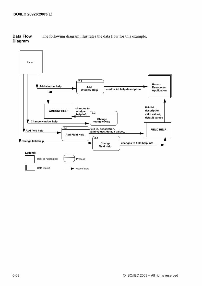
ISO/IEC 20926:2003(E)
6-68 © ISO/IEC 2003 – All rights reserved
Data Flow Diagram
The following diagram illustrates the data flow for this example.
User
WINDOW HELP
ChangeField Help
Add window helpwindow id, help description
help info
Change window help
Change field helpchanges to field help info
2.4
FIELD HELPAdd field helpAdd Field Help
2.3 field id, description,valid values, default values,
Change
2.2
Window Help
Add
2.1
Window Help
changes towindow
Human ResourcesApplication
field id,
valid values,description,
default values
Legend:
User or Application
Data Stored Flow of Data
Process

ISO/IEC 20926:2003(E)
© ISO/IEC 2003 – All rights reserved 6-69
Identify EIFs From the requirements for the Human Resources (HR) application, there are
two groups of data:
• Window help
• Field help
The following table shows the summary analysis to determine whether window help is an EIF for the HR application.
EIF Identification Rules Does the Rule Apply?
The group of data or control information is logical and user identifiable.
Yes. Users require a centralized window help facility to customize help.
The group of data is referenced by, and external to, the application being counted.
Yes. The data is external to the HR application.
The group of data is not maintained by the application being counted.
Yes. The rule applies.
The group of data is maintained in an ILF of another application.
Yes. It is counted as an ILF in the Help application.
Window help information is an EIF in the HR application because the
information is retrieved by the HR application. Window help is maintained in the Help application, where it is counted as an ILF.
The following table shows the summary results of the analysis to determine
whether the field help is an EIF.
EIF Identification Rules Does the Rule Apply?
The group of data or control information is logical and user identifiable.
Yes. Users require a centralized field help facility to customize help.
The group of data is referenced by, and external to, the application being counted.
Yes. Field help is maintained by the Help application, therefore, it is external to the HR application.
The group of data is not maintained by the application being counted.
Yes.
The group of data is maintained in an ILF of another application.
Yes.
Field help information is an EIF in the HR application because the
information is retrieved by the HR application. The field help information is maintained in the Help system where it is counted as an ILF.
ISO/IEC 20926:2003(E)
6-70 © ISO/IEC 2003 – All rights reserved
Count RETs and DETs
Count the number of data element types (DETs) and record element types (RETs).
For DETs, look at each field associated with the window and field help and use the DET counting rules to count DETs.
The fields for window help include:
• Window identifier
• Business function description. The following table shows the DET analysis for window help.
EIF DET Counting Rules Does the Rule Apply? Count a DET for each unique user recognizable, non-repeated field maintained in or retrieved from the ILF or EIF through the execution of an elementary process.
All fields are user recognizable.
When two applications maintain and/or reference the same ILF/EIF, but each maintains/references separate DETs, count only the DETs being used by each application to size the ILF/EIF.
This data is maintained by the Help system.
Count a DET for each piece of data required by the user to establish a relationship with another ILF or EIF.
There is no data of this type.
The following list shows the fields for field help:
• Window identifier
• Field indicator
• Field description
• Default values
• Valid values

ISO/IEC 20926:2003(E)
© ISO/IEC 2003 – All rights reserved 6-71
The following table shows the DET analysis for field help.
EIF DET Counting Rules Does the Rule Apply? Count a DET for each unique user recognizable, non-repeated field maintained in or retrieved from the ILF or EIF through the execution of an elementary process.
All fields are user recognizable.
When two applications maintain and/or reference the same ILF/EIF, but each maintains/references separate DETs, count only the DETs being used by each application to size the ILF/EIF.
This data is maintained by the Help system.
Count a DET for each piece of data required by the user to establish a relationship with another ILF or EIF.
There is no data of this type.
For RETs, identify subgroups based on the RET counting rules.
RET Counting Rules Does the Rule Apply?
Count a RET for each optional or mandatory subgroup of the ILF or EIF.
Or
There are no subgroups for either the window help or field help EIF.
If there are no subgroups, count the ILF or EIF as one RET.
Because there are no subgroups, count one RET for each EIF (window help and field help).
There are no subgroups; therefore, the help information has only one RET for
each EIF. The RET and DET totals for the window help EIF are shown in the
following table.
RETs DETs
• Window help information
• Window identifier
• Business function description
Total 1 RET Total 2 DETs

ISO/IEC 20926:2003(E)
6-72 © ISO/IEC 2003 – All rights reserved
The RET and DET totals for the field help EIF are shown in the following
table.
RETs DETs
• Field help information • Window identifier
• Field indicator
• Field description
• Default values
• Valid values
Total 1 RET Total 5 DETs

ISO/IEC 20926:2003(E)
© ISO/IEC 2003 – All rights reserved 6-73
Example: Data Conversion
User Requirements
An organization has purchased a new HR application package. The organization is required to convert its employee file from its existing HR System to a replacement system.
The old system did not provide the capability to maintain employee dependent information. The dependent information is initialized when existing employees are migrated to the new application.
Data Model The following diagram shows the data for the two applications.
HR ApplicationNew
HR ApplicationOld
SALARIED_EMPLHOURLY_EMPL
EMPLOYEE
DEPENDENT
SALARIED_EMPLHOURLY_EMPL
EMPLOYEE
Legend:
Optional One-to-Many Relationship
Attribute Entity Type
Entity Type
Entity Subtype
The employee file from the old HR application is used to add employees to
the new HR application.
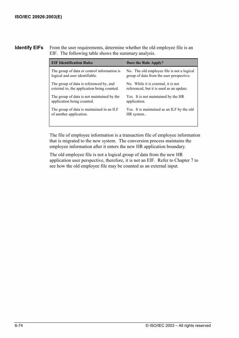
ISO/IEC 20926:2003(E)
6-74 © ISO/IEC 2003 – All rights reserved
Identify EIFs From the user requirements, determine whether the old employee file is an
EIF. The following table shows the summary analysis.
EIF Identification Rules Does the Rule Apply?
The group of data or control information is logical and user identifiable.
No. The old employee file is not a logical group of data from the user perspective.
The group of data is referenced by, and external to, the application being counted.
No. While it is external, it is not referenced, but it is used as an update.
The group of data is not maintained by the application being counted.
Yes. It is not maintained by the HR application.
The group of data is maintained in an ILF of another application.
Yes. It is maintained as an ILF by the old HR system..
The file of employee information is a transaction file of employee information
that is migrated to the new system. The conversion process maintains the employee information after it enters the new HR application boundary.
The old employee file is not a logical group of data from the new HR application user perspective, therefore, it is not an EIF. Refer to Chapter 7 to see how the old employee file may be counted as an external input.
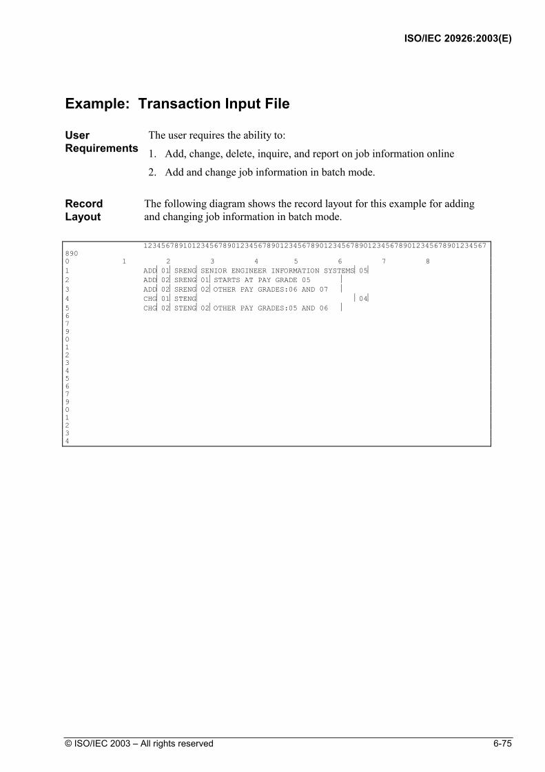
ISO/IEC 20926:2003(E)
© ISO/IEC 2003 – All rights reserved 6-75
Example: Transaction Input File
User Requirements
The user requires the ability to:
1. Add, change, delete, inquire, and report on job information online
2. Add and change job information in batch mode.
Record Layout
The following diagram shows the record layout for this example for adding and changing job information in batch mode.
123456789101234567890123456789012345678901234567890123456789012345678901234567890 0 1 2 3 4 5 6 7 8 1 ADD01SRENGSENIOR ENGINEER INFORMATION SYSTEMS05 2 ADD02SRENG01STARTS AT PAY GRADE 05 3 ADD02SRENG02OTHER PAY GRADES:06 AND 07 4 CHG01STENG 04 5 CHG02STENG02OTHER PAY GRADES:05 AND 06 6 7 9 0 1 2 3 4 5 6 7 9 0 1 2 3 4

ISO/IEC 20926:2003(E)
6-76 © ISO/IEC 2003 – All rights reserved
Record Descriptions
The following table includes descriptions for each record type.
Record Position Description
01 1-3 Transaction type
4-5 Record type
6-10 Job number
11-45 Job name
46-47 Job pay grade
02 1-3 Transaction type
4-5 Record type
6-10 Job ID
11-12 Job description line number
13-41 Job description lines
Identify EIFs From the user requirements, determine whether the transaction file is an EIF.
The following table shows the summary analysis.
EIF Identification Rules Does the Rule Apply?
The group of data or control information is logical and user identifiable.
Yes. Data is grouped into transactions which enter the application boundary to maintain the job ILF.
The group of data is referenced by, and external to, the application being counted.
Yes. The transaction file is outside the boundary ready to be processed.
The group of data is not maintained by the application being counted.
No. It is not maintained.
The group of data is maintained in an ILF of another application.
No. The transactions entering the boundary to update the job ILF make up the elementary processes. There is no elementary process to update the transaction file.
There are no EIFs for this example. Refer to Chapter 7 to see the explanation
of how an input transaction file may be counted as an external input.
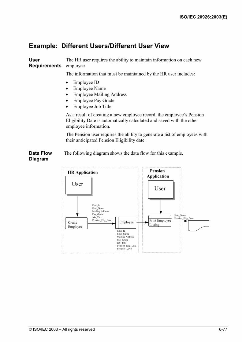
ISO/IEC 20926:2003(E)
© ISO/IEC 2003 – All rights reserved 6-77
Example: Different Users/Different User View
User Requirements
The HR user requires the ability to maintain information on each new employee.
The information that must be maintained by the HR user includes:
• Employee ID • Employee Name • Employee Mailing Address • Employee Pay Grade • Employee Job Title
As a result of creating a new employee record, the employee’s Pension Eligibility Date is automatically calculated and saved with the other employee information.
The Pension user requires the ability to generate a list of employees with their anticipated Pension Eligibility date.
Data Flow Diagram
The following diagram shows the data flow for this example.
User
EmployeeCreateEmployee
Print EmployeeListing
HR Application Pension Application
Emp_IdEmp_NameMailing AddressPay_GradeJob_TitlePension_Elig_DateSecurity_Level
User
Emp_IdEmp_NameMailing AddressPay_GradeJob_TitlePension_Elig_Date
Emp_NamePension_Elig_Date
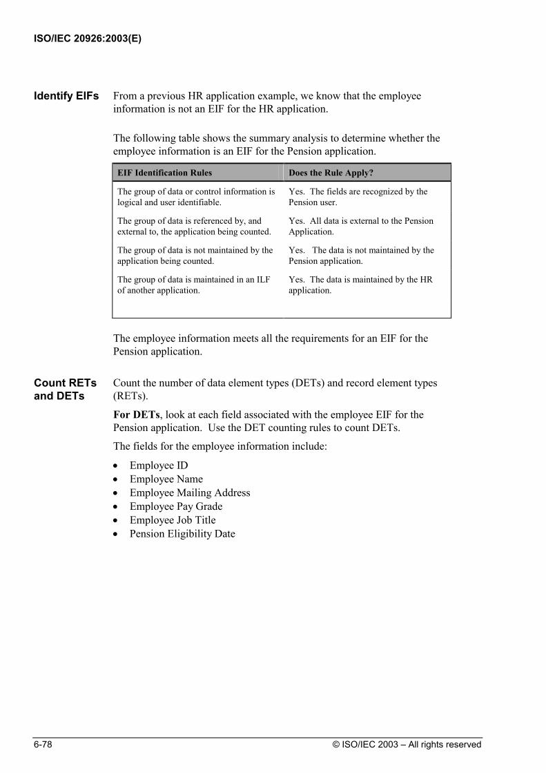
ISO/IEC 20926:2003(E)
6-78 © ISO/IEC 2003 – All rights reserved
Identify EIFs From a previous HR application example, we know that the employee
information is not an EIF for the HR application. The following table shows the summary analysis to determine whether the
employee information is an EIF for the Pension application.
EIF Identification Rules Does the Rule Apply?
The group of data or control information is logical and user identifiable.
Yes. The fields are recognized by the Pension user.
The group of data is referenced by, and external to, the application being counted.
Yes. All data is external to the Pension Application.
The group of data is not maintained by the application being counted.
Yes. The data is not maintained by the Pension application.
The group of data is maintained in an ILF of another application.
Yes. The data is maintained by the HR application.
The employee information meets all the requirements for an EIF for the
Pension application.
Count RETs and DETs
Count the number of data element types (DETs) and record element types (RETs).
For DETs, look at each field associated with the employee EIF for the Pension application. Use the DET counting rules to count DETs.
The fields for the employee information include:
• Employee ID • Employee Name • Employee Mailing Address • Employee Pay Grade • Employee Job Title • Pension Eligibility Date

ISO/IEC 20926:2003(E)
© ISO/IEC 2003 – All rights reserved 6-79
The following table shows the DET analysis for employee information for the
Pension application.
EIF DET Counting Rules Does the Rule Apply? Count a DET for each unique user recognizable, non-repeated field maintained in or retrieved from the ILF or EIF through the execution of an elementary process.
Only the Employee Name and the Pension Eligibility Date are recognized by the Pension user.
When two applications maintain and/or reference the same ILF/EIF, but each maintains/references separate DETs, count only the DETs being used by each application to size the ILF/EIF.
The Pension application only uses the Employee Name and the Pension Eligibility Date.
Count a DET for each piece of data required by the user to establish a relationship with another ILF or EIF.
There is no data of this type.
The following list shows the fields for the employee EIF for the Pension
application:
• Employee Name • Pension Eligibility Date
For RETs, identify subgroups based on the RET counting rules.
RET Counting Rules Does the Rule Apply?
Count a RET for each optional or mandatory subgroup of the ILF or EIF.
Or
There are no subgroups.
If there are no subgroups, count the ILF or EIF as one RET.
Because there are no subgroups, count one RET for each EIF.
There are no subgroups; therefore the employee information has only one
RET.
The RET and DET totals for the Employee EIF in the Pension application.
RETs DETs
• Employee information
• Employee Name • Pension Eligibility Date
Total 1 RET Total 2 DETs

ISO/IEC 20926:2003(E)
6-80 © ISO/IEC 2003 – All rights reserved
Example: Multiple Data Uses
User Requirements
The HR user requires the ability to generate a listing of all of the employees.
The information that must be displayed for each employee includes:
• Employee ID • Employee Name
Data Flow Diagram
The following diagram shows the data flow for this example.
EmployeeCreateEmployee
Print EmployeeListing
HR Application
Emp_IdEmp_NameMailing AddressPay_GradeJob_TitlePension_Elig_DateSecurity_Level
User
Emp_IdEmp_NameMailing AddressPay_GradeJob_TitlePension_Elig_Date
Emp_IDEmp_Name

ISO/IEC 20926:2003(E)
© ISO/IEC 2003 – All rights reserved 6-81
Identify EIFs The following table shows the summary analysis to determine whether the
employee information that is used to create the employee listing is an EIF for the HR application.
EIF Identification Rules Does the Rule Apply?
The group of data or control information is logical and user identifiable.
Yes. All data is recognized by the user.
The group of data is referenced by, and external to, the application being counted.
No. The data and the process of producing the employee listing is not external to the HR application.
The group of data is not maintained by the application being counted.
No. The data is maintained by the application.
The group of data is maintained in an ILF of another application.
Not applicable.
The employee listing information used for creating the employee information
is not an EIF for the HR application.

ISO/IEC 20926:2003(E)
6-82 © ISO/IEC 2003 – All rights reserved
Summary of EIFs, RETs and DETs Counted
This section summarizes the EIFs, RETs, and DETs counted before calculating the complexity and contribution to the unadjusted function point count.
Summary of EIFs Identified
The following table shows the EIF count for the HR application. It also lists the data that was not counted.
EIFs Identified Not Counted • Location information
• Conversion information
• Window help
• Field help
• Old HR system employee data
• Transaction Input File
• Employee listing information
The following table shows the EIF count for the Pension application. It also
lists the data that was not counted.
EIFs Identified Not Counted • Employee information
Summary RET/DET Count
The RET and DET counts for the HR application are recorded in the following table.
EIFs RETs DETs
Location information 1 6
Conversion information 1 2
Window help information 1 2
Field help information 1 5 The RET and DET counts for the Pension application are recorded in the
following table.
EIFs RETs DETs
Employee information 1 2

ISO/IEC 20926:2003(E)
© ISO/IEC 2003 – All rights reserved 6-83
EIF Complexity and Contribution
This section describes the final steps to determine EIF complexity and contribution to the unadjusted function point count.
The final steps are to:
1. Rate the EIF complexity.
2. Translate the complexity to unadjusted function points.
3. Calculate the external interface files' contribution to the total unadjusted function point count.
Rate EIF Complexity
The functional complexity is rated as low, average, or high. The following RET/DET matrix rates the EIF complexity.
1 to 19 DETs 20 to 50 DETs 51 or more DETs
1 RET Low Low Average
2 to 5 RETs Low Average High
6 or more RETs Average High High
Legend: RET = Record Element Type DET = Data Element Type
The following table shows the functional complexity for each EIF within the
HR application.
EIFs
RETs
DETs
Functional Complexity
Location information 1 6 Low
Conversion information 1 2 Low
Window help information 1 2 Low
Field help information 1 5 Low
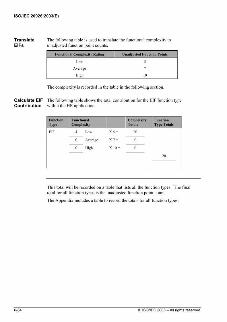
ISO/IEC 20926:2003(E)
6-84 © ISO/IEC 2003 – All rights reserved
Translate EIFs
The following table is used to translate the functional complexity to unadjusted function point counts.
Functional Complexity Rating Unadjusted Function Points
Low 5
Average 7
High 10
The complexity is recorded in the table in the following section.
Calculate EIF Contribution
The following table shows the total contribution for the EIF function type within the HR application.
Function Type
Functional Complexity
Complexity Totals
Function Type Totals
EIF 4 Low X 5 = 20 0 Average X 7 = 0 0 High X 10 = 0 20
This total will be recorded on a table that lists all the function types. The final
total for all function types is the unadjusted function point count.
The Appendix includes a table to record the totals for all function types.

ISO/IEC 20926:2003(E)
© ISO/IEC 2003 – All rights reserved 7-1
DetermineType of Count
7 Count
Transactional
Functions Determine
ValueAdjustment
Factor
CountData
Functions
Identify Counting Scopeand Application
Boundary
Introduction Transactional functions represent the functionality provided to the user for the
processing of data by an application. Transactional functions are defined as external inputs (EIs), external outputs (EOs), and external inquiries (EQs).
This chapter defines EI, EO, and EQ transactional functions and includes the associated function point counting rules and procedures. The chapter concludes with detailed examples for each function.
Contents This chapter includes the following sections:
Topic See Page Definitions: EIs, EOs and EQs 7-3
External Inputs 7-3
External Outputs 7-3
External Inquiry 7-3
Summary of the Functions Performed by EIs, EOs and EQs 7-4
Definitions for Embedded Terms 7-5
Summary of Processing Logic Used by EIs, EOs and EQs 7-8
EI/EO/EQ Counting Rules 7-9
Summary of Counting Procedures 7-9
Continued on next page

ISO/IEC 20926:2003(E)
7-2 © ISO/IEC 2003 – All rights reserved
Topic See Page
Elementary Process Identification Rules 7-10
Transactional Functions Counting Rules 7-11
Primary Intent Description for EIs 7-11
External Input Counting Rules 7-11
Primary Intent Description for EOs and EQs 7-12
Shared EO and EQ Counting Rules 7-12
Additional External Output Counting Rules 7-12
Additional External Inquiry Counting Rules 7-13
Complexity and Contribution Definitions and Rules 7-13
FTR Definition 7-13
DET Definition 7-13
EI Complexity and Contribution Rules 7-14
FTR Rules for an EI 7-14
DET Rules for an EI 7-14
EO/EQ Complexity and Contribution Rules 7-16
Shared FTR Rules for EOs and EQs 7-16
Additional FTR Rules for an EO 7-16
Shared DET Rules for EOs and EQs 7-16
EI, EO and EQ Counting Procedures 7-18
Procedure Diagram 7-18
Identification Procedures 7-19
Complexity and Contribution Procedures 7-21
Hints to Help with Counting EIs, EOs and EQs 7-24
Additional Hints to Help Counting EOs and EQs 7-26
Elementary Process Identification Examples 7-27
EI/EO/EQ Counting Examples 7-45
EI Counting Examples 7-52
EO Counting Examples 7-89
EQ Counting Examples 7-123

ISO/IEC 20926:2003(E)
© ISO/IEC 2003 – All rights reserved 7-3
Definitions: EIs, EOs and EQs
This section includes the definitions of EIs, EOs and EQs. Embedded terms within the definitions are defined, and examples are included throughout this definition section.
External Inputs An external input (EI) is an elementary process that processes data or control
information that comes from outside the application boundary. The primary intent of an EI is to maintain one or more ILFs and/or to alter the behavior of the system.
External Outputs An external output (EO) is an elementary process that sends data or control
information outside the application boundary. The primary intent of an external output is to present information to a user through processing logic other than, or in addition to, the retrieval of data or control information . The processing logic must contain at least one mathematical formula or calculation, or create derived data. An external output may also maintain one or more ILFs and/or alter the behavior of the system.
External Inquiry An external inquiry (EQ) is an elementary process that sends data or control
information outside the application boundary. The primary intent of an external inquiry is to present information to a user through the retrieval of data or control information from an ILF of EIF. The processing logic contains no mathematical formulas or calculations, and creates no derived data. No ILF is maintained during the processing, nor is the behavior of the system altered.

ISO/IEC 20926:2003(E)
7-4 © ISO/IEC 2003 – All rights reserved
Summary of the Functions Performed by EIs, EOs and EQs The main difference between the transactional function types is their primary
intent. The table below summarizes functions that may be performed by each transactional function type, and specifies the primary intent of each. Note the primary intent for an EI—this is the main difference from EOs and EQs. Some of the differences between EOs and EQs are that an EO may perform the functions of altering the behavior of the system or maintaining one or more ILFs when performing the primary intent of presenting information to the user. Other differences are identified in the section below that summarizes forms of processing logic used by each transactional function.
Transactional Function Type:
Function: EI EO EQ Alter the behavior of the system PI F N/A Maintain one or more ILFs PI F N/A Present information to a user F PI PI
Legend:
PI the primary intent of the transactional function type
F a function of the transactional function type, but is not the primary intent and is sometimes present
N/A the function is not allowed by the transactional function type

ISO/IEC 20926:2003(E)
© ISO/IEC 2003 – All rights reserved 7-5
Definitions for Embedded Terms The following paragraphs further define EIs, EOs and EQs by defining terms
used within the above definitions. Elementary Process
An elementary process is the smallest unit of activity that is meaningful to the user(s).
For example, a user requires the ability to add a new employee to the application. The user definition of employee includes salary and dependent information. From the user perspective, the smallest unit of activity is to add a new employee. Adding one of the pieces of information, such as salary or dependent, is not an activity that would qualify as an elementary process.
The elementary process must be self-contained and leave the business of the application being counted in a consistent state.
For example, the user requirements to add an employee include setting up salary and dependent's information. If all the employee information is not added, an employee has not yet been created. Adding some of the information alone leaves the business of adding an employee in an inconsistent state. If both the employee salary and dependent information is added, this unit of activity is completed and the business is left in a consistent state.
Control Information
Control Information is data that influences an elementary process of the application being counted. It specifies what, when, or how data is to be processed.
For example, someone in the payroll department establishes payment cycles to schedule when the employees for each location are to be paid. The payment cycle, or schedule, contains timing information that affects when the elementary process of paying employees occurs.
Maintained The term maintained is the ability to modify data through an elementary
process.
Examples include, but are not limited to, add, change, delete, populate, revise, update, assign, and create.
User A user is any person that specifies Functional User Requirements and/or any
person or thing that communicates or interacts with the software at any time.
Examples include people within the HR department who interact with the application to set up employees, and the Benefits application that interacts with the HR application to receive information about employees’ dependents.
ISO/IEC 20926:2003(E)
7-6 © ISO/IEC 2003 – All rights reserved
Processing Logic
Processing logic is defined as requirements specifically requested by the user to complete an elementary process. Those requirements may include the following actions:
1. Validations are performed
For example, when adding a new employee to an organization, the employee process has processing logic that validates the information being added.
2. Mathematical formulas and calculations are performed
For example, when reporting on all employees within an organization the process includes calculating the total number of salaried employees, hourly employees and all employees.
3. Equivalent values are converted
For example, an elementary process references currency conversion rates from US dollars to other currencies. The conversion is accomplished by retrieving values from tables, so calculations need not be performed.
4. Data is filtered and selected by using specified criteria to compare multiple sets of data
For example, to generate a list of employees by assignment, an elementary process compares the job number of a job assignment to select and lists the appropriate employees with that assignment.
5. Conditions are analyzed to determine which are applicable
For example, processing logic exercised by the elementary process when an employee is added and will depend on whether an employee is paid based on salary or hours worked.
6. One or more ILFs are updated
For example, when adding an employee, the elementary process updates the employee ILF to maintain the employee data.
7. One or more ILFs or EIFs are referenced
For example, when adding an employee, the currency EIF is referenced to use the correct US dollar conversion rate to determine an employee’s hourly rate.
8. Data or control information is retrieved
For example, to view a list of possible pay grades, pay grade information is retrieved.

ISO/IEC 20926:2003(E)
© ISO/IEC 2003 – All rights reserved 7-7
9. Derived data is created by transforming existing data to create additional data
For example, to determine (derive) a patient’s registration number (e.g., SMIJO01), the following data is concatenated:
• the first three letters of the patient’s last name (e.g., SMI for Smith)
• the first two letter of the patient’s first name (e.g., JO for John)
• a unique two-digit sequence number (starting with 01)
10. Behavior of the system is altered
For example, the behavior of the elementary process of paying employees is altered when a change is made to pay them every other Friday versus on the 15th and the last day of the month.
11. Prepare and present information outside the boundary
For example, a list of employees displayed for the user.
12. Capability exists to accept data or control information that enters the application boundary
For example, a user enters several pieces of information to add a customer order to the system.
13. Data is resorted or rearranged
For example, a user requests the list of employees in alphabetical order.
Note: Resorting or rearranging a set of data does not impact the identification of the type or uniqueness of a transactional function.

ISO/IEC 20926:2003(E)
7-8 © ISO/IEC 2003 – All rights reserved
Summary of Processing Logic Used by EIs, EOs and EQs The following table summarizes which forms of processing logic may be
performed by EIs, EOs, and EQs. For each transactional function type, certain types of processing logic must be performed to accomplish the primary intent of that type.
Transactional Functional Type:
Form of Processing Logic: EI EO EQ 1. Validations are performed c c c 2. Mathematical formula and calculations
are performed c m* n
3. Equivalent values are converted c c c 4. Data is filtered and selected by using
specified criteria to compare multiple sets of data
c
c
c
5. Conditions are analyzed to determine which are applicable
c c c
6. At least one ILF is updated m* m* n 7. At least one ILF or EIF is referenced c c m 8. Data or control information is retrieved c c m 9. Derived data is created c m* n 10. Behavior of the system is altered m* m* n 11. Prepare and present information outside
the boundary c m m
12. Capability to accept data or control information that enters the application boundary.
m c c
13. Resorting or rearranging a set of data c c c
Legend:
m it is mandatory that the function type perform the form of processing logic
m* it is mandatory that the function type perform at least one of these (m*) forms of processing logic
c the function type can perform the form of processing logic, but it is not mandatory
n function type cannot perform the form of processing logic

ISO/IEC 20926:2003(E)
© ISO/IEC 2003 – All rights reserved 7-9
EI/EO/EQ Counting Rules
This section defines the rules that apply when counting EIs, EOs and EQs.
Summary of Counting Procedures This summary is included to show the rules in the context of the EI, EO, and
EQ counting procedures.
Note: The detailed procedures begin on page 7-18.
The EI, EO and EQ counting procedures include the following steps:
Step Action
1 Identify the elementary processes.
2 Determine the primary intent of the identified elementary processes, and classify as an EI, EO, or EQ.
3 Validate against the transaction (EI, EO, EQ) identification rules.
4 Determine the transaction (EI, EO, EQ) complexity.
5 Determine the transaction (EI, EO, EQ) contribution to the unadjusted function point count.
The rules are explained in the following paragraphs.

ISO/IEC 20926:2003(E)
7-10 © ISO/IEC 2003 – All rights reserved
Elementary Process Identification Rules To identify elementary processes, look for user activities occurring in the
application.
All of the following counting rules must apply for the process to be identified as an elementary process.
The process is the smallest unit of activity that is meaningful to the user.
The process is self-contained and leaves the business of the application in a consistent state.

ISO/IEC 20926:2003(E)
© ISO/IEC 2003 – All rights reserved 7-11
Transactional Functions Counting Rules
To classify each elementary process, determine which of the primary intent descriptions apply, and use the associated rules to identify a specific transactional function type.
Primary Intent Description for EIs
The primary intent of an elementary process is to maintain an ILF or alter the behavior of the system.
External Input Counting Rules
For each elementary process that has a primary intent to maintain one or more ILFs or to alter the behavior of the system, apply the following rules to determine if the function should be classified as an external input. All of the rules must apply for the elementary process to be counted as a unique occurrence of an external input.
The data or control information is received from outside the application boundary.
At least one ILF is maintained if the data entering the boundary is not control information that alters the behavior of the system.
For the identified process, one of the following three statements must apply:
− Processing logic is unique from the processing logic performed by other external inputs for the application.
− The set of data elements identified is different from the sets identified for other external inputs for the application.
− The ILFs or EIFs referenced are different from the files referenced by other external inputs in the application.
ISO/IEC 20926:2003(E)
7-12 © ISO/IEC 2003 – All rights reserved
Primary Intent Description for EOs and EQs
The primary intent of the elementary process is to present information to a user.
Shared EO and EQ Counting Rules
For each elementary process that has a primary intent to present information to a user, apply the following rules to determine if the process may be classified as an external output or external inquiry. All of the rules must apply for the elementary process to be counted as a unique occurrence of an external output or external inquiry.
The function sends data or control information external to the application boundary.
For the identified process, one of the following three statements must apply:
− Processing logic is unique from the processing logic performed by other external outputs or external inquiries for the application.
− The set of data elements identified is different from the sets identified for other external outputs and external inquiries in the application.
− The ILFs or EIFs referenced are different from the files referenced by other external outputs and external inquiries in the application.
Additional External Output Counting Rules
In addition to adhering to all shared EO and EQ rules, one of the following rules must apply for the elementary process to be counted as a unique external output.
The processing logic of the elementary process contains at least one mathematical formula or calculation.
The processing logic of the elementary process creates derived data.
The processing logic of the elementary process maintains at least one ILF.
The processing logic of the elementary process alters the behavior of the system.

ISO/IEC 20926:2003(E)
© ISO/IEC 2003 – All rights reserved 7-13
Additional External Inquiry Counting Rules
In addition to adhering to all shared EO and EQ rules, all of the following rules must apply for the elementary process to be counted as a unique external inquiry.
The processing logic of the elementary process retrieves data or control information from an ILF or EIF.
The processing logic of the elementary process does not contain a mathematical formula or calculation.
The processing logic of the elementary process does not create derived data.
The processing logic of the elementary process does not maintain an ILF.
The processing logic of the elementary process does not alter the behavior of the system.
Complexity and Contribution Definitions and Rules The number of EIs, EOs, and EQs and their relative functional complexities
determine the contribution of the transactional functions to the unadjusted function point count.
Assign each identified EI, EO and EQ a functional complexity based on the number of file types referenced (FTRs) and data element types (DETs).
FTR Definition
A file type referenced is
• An internal logical file read or maintained by a transactional function or
• An external interface file read by a transactional function
DET Definition
A data element type is a unique user recognizable, non-repeated field.
ISO/IEC 20926:2003(E)
7-14 © ISO/IEC 2003 – All rights reserved
EI Complexity and Contribution Rules
This section defines FTR and DET rules used to determine the complexity and contribution of external inputs.
FTR Rules for an EI
The following rules apply when counting FTRs:
Count an FTR for each ILF maintained.
Count an FTR for each ILF or EIF read during the processing of the external input.
Count only one FTR for each ILF that is both maintained and read.
DET Rules for an EI
The following rules apply when counting DETs:
Count one DET for each user recognizable, non-repeated field that enters or exits the application boundary and is required to complete the external input.
For example, job name and pay grade are two fields that the user provides when adding a job.
Do not count fields that are retrieved or derived by the system and stored on an ILF during the elementary process if the fields did not cross the application boundary.
For example, when the customer order is added to the system, the unit price is automatically retrieved for each ordered item and stored on the billing record. The unit price would not be counted as a DET for the EI because it did not cross the boundary when the user adds the customer order.
For example, in order to maintain the US hourly rate for hourly employees working in other countries with other currencies, the local hourly rate is provided by the user. During the processing of all the pieces of data provided to add an employee, a conversion rate is retrieved from the currency system to calculate the US hourly rate. The calculated US hourly rate is maintained on the employee ILF as a result of adding the employee. The US hourly rate would not be counted as a DET for the EI because it does not enter the boundary, but is internally calculated (i.e., it is derived data).

ISO/IEC 20926:2003(E)
© ISO/IEC 2003 – All rights reserved 7-15
Count one DET for the capability to send a system response message outside the application boundary to indicate an error occurred during processing, confirm that processing is complete or verify that processing should continue.
For example, if a user tries to add an existing employee to a Human Resources application, the system generates one of several error messages and the incorrect field is highlighted. Count one DET that includes all the system responses which indicate the error conditions, confirm that processing is complete or verify that processing should continue.
Count one DET for the ability to specify an action to be taken even if there are multiple methods for invoking the same logical process.
For example, if the user can initiate the adding of an employee clicking on the OK button or by pressing a PF key, count one DET for the ability to initiate the process.

ISO/IEC 20926:2003(E)
7-16 © ISO/IEC 2003 – All rights reserved
EO/EQ Complexity and Contribution Rules
This section defines FTR and DET rules used to determine the complexity and contribution of external outputs and external inquiries.
Shared FTR Rules for EOs and EQs
The following rule applies when counting FTRs for both EOs and EQs:
Count one FTR for each ILF or EIF read during the processing of the elementary process.
Additional FTR Rules for an EO
The following additional rules apply when counting FTRs for EOs:
Count one FTR for each ILF maintained during the processing of the elementary process.
Count only one FTR for each ILF that is both maintained and read during the elementary process.
Shared DET Rules for EOs and EQs
The following rules apply when counting DETs for both EOs and EQs.
Count one DET for each user recognizable, non-repeated field that enters the application boundary and is required to specify when, what and/or how the data is to be retrieved or generated by the elementary process.
For example (EO/EQ), to generate a list of employees, employee name is a field the user provides when indicating which employees to list.
Count one DET for each user recognizable, non-repeated field that exits the boundary.
For example (EO/EQ), a text message may be a single word, sentence, or phrase—a line or paragraph included on a report to indicate an explanatory comment counts as a single DET.
For example (EO/EQ), an account number or date physically stored in multiple fields is counted as one DET when it is required as a single piece of information.
For example (EO/EQ), a pie chart might have a category label and a numerical equivalent in a graphical output. Count two DETs —one for designating the category and one for the numerical value.
If a DET both enters and exits the boundary, count it only once for the elementary process.

ISO/IEC 20926:2003(E)
© ISO/IEC 2003 – All rights reserved 7-17
Count one DET for the capability to send a system response message outside the application boundary to indicate an error occurred during processing, confirm that processing is complete or verify that processing should continue.
For example (EO/EQ), if a user tries to request a listing, but does not have access to the information, count one DET for the system response.
Count one DET for the ability to specify an action to be taken even if there are multiple methods for invoking the same logical process.
For example (EO/EQ), if the user can initiate the generation of a report by clicking on the OK button or by pressing a PF key, count one DET for the ability to initiate the report.
Do not count fields that are retrieved or derived by the system and stored on an ILF during the elementary process if the fields did not cross the application boundary.
For example (EO), when a paycheck is printed, a status field on the employee ILF is updated to indicate that the check has been printed. Do not count the status field as a DET since it did not cross the boundary.
Do not count literals as DETs.
For example (EO/EQ), literals include report titles, screen or panel identification, column headings, and field titles.
Do not count paging variables or system-generated stamps.
For example (EO/EQ), system-generated variables and stamps include
− Page numbers
− Positioning information such as "Rows 37 to 54 of 211"
− Paging commands such as previous, next, and paging arrows on a GUI application
− Date and time fields if they are displayed.

ISO/IEC 20926:2003(E)
7-18 © ISO/IEC 2003 – All rights reserved
EI, EO and EQ Counting Procedures
This section includes detailed explanations of EI, EO and EQ counting
procedures.
Procedure Diagram The following diagram shows the high-level procedure for counting EIs, EOs
and EQs:
CountTransactional
FunctionTypes
Ele menta ryIdentify
Processes1
Functions thatMaintain an ILF orAlter Behavior of
the System
Functions thatPresent
Information to theUse r and
IdentifyPrimaryintent of
ElementaryProcesses
andClassify
Per formcalculations,derive data ,
update a n ILF ,or alter system
behavior
Do notPer form
calculations,derive data ,
update a n ILF ,or alter system
behavior
ValidateAgainst
EICounting
rules3
DetermineEI
complexity4
DetermineEI
contribution5
ValidateAgainst
EOCounting
Rules3
ValidateAga inst
EQCounting
Rules3
DetermineEO
complexity4
DetermineEQ
complexity4
DetermineEO
contribution5
DetermineEQ
contribution5
The following paragraphs explain the steps for each activity.

ISO/IEC 20926:2003(E)
© ISO/IEC 2003 – All rights reserved 7-19
Identification Procedures Follow these steps to identify EIs, EOs and EQs:
Step Action Rule Set(s) to Use Page #
1 Identify Elementary Processes
Elementary Process Identification Rules
7-10
2 Identify Primary Intent of Elementary Processes, and classify as an EI, EO, or EQ.
Transactional Function Type Counting Rules - Primary Intent Descriptions for:
• EIs 7-11 • EOs and EQs 7-12
For the Elementary Processes where the Primary Intent is to maintain an ILF or to alter the behavior of the system:
3 Validate against the EI identification rules.
Transactional Function Type Counting Rules:
• External Input Counting Rules
7-11
4 Determine EI Complexity Refer to Complexity and Contribution Procedures
7-21
5 Determine EI Contribution Refer to Complexity and Contribution Procedures
7-23
For the Elementary Processes where the Primary Intent is to present information to the user and that perform calculations, derive data, update an ILF, or alter the behavior of the system.
3 Validate against the EO identification rules.
Transactional Function Type Counting Rules:
• Shared EO and EQ Counting Rules
7-12
• Additional EO Counting Rules
7-12
Continued on next page

ISO/IEC 20926:2003(E)
7-20 © ISO/IEC 2003 – All rights reserved
Step Action Rule Set(s) to Use Page #
4 Determine EO Complexity Refer to Complexity and Contribution Procedures
7-22
5 Determine EO Contribution Refer to Complexity and Contribution Procedures
7-23
For the Elementary Processes where the Primary Intent is to present information to the user and that do not perform calculations, derive data, update an ILF, or alter the behavior of the system.
3 Validate against the EQ identification rules.
Transactional Function Type Counting Rules:
• Shared EO and EQ Counting Rules
7-12
• Additional EQ Counting Rules
7-13
4 Determine EQ Complexity Refer to Complexity and Contribution Procedures
7-22
5 Determine EQ Contribution Refer to Complexity and Contribution Procedures
7-23

ISO/IEC 20926:2003(E)
© ISO/IEC 2003 – All rights reserved 7-21
Complexity and Contribution Procedures Follow these steps to calculate EI, EO and EQ complexity and contribution to
the unadjusted function point count:
Step Complexity Procedure
4
External Inputs:
Use the Complexity Definitions and Rules for EIs that begin on page 7-16 to identify and count the number of FTRs and DETs.
Rate the complexity of the EI using the following complexity matrix.
1 to 4 DET 5 to 15 DET 16 or more DET
0 to 1 FTR Low Low Average
2 FTRs Low Average High
3 or more FTRs Average High High

ISO/IEC 20926:2003(E)
7-22 © ISO/IEC 2003 – All rights reserved
Step Complexity Procedure
4 External Outputs and External Inquiries:
Use the Complexity Definitions and Rules for EOs or EQs that begin on page 7-16 to identify and count the number of FTRs and DETs.
Rate the complexity of the EOs or EQs using the following complexity matrix. Remember to use the cumulative number of FTRs and DETs, ignoring duplicates, to rate the complexity.
1 to 5 DET 6 to 19 DET 20 or more DET
0 to 1 FTR Low Low Average
2 to 3 FTRs Low Average High
4 or more FTRs Average High High
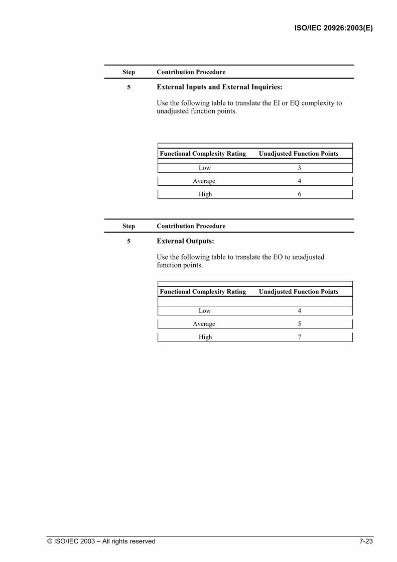
ISO/IEC 20926:2003(E)
© ISO/IEC 2003 – All rights reserved 7-23
Step Contribution Procedure
5 External Inputs and External Inquiries:
Use the following table to translate the EI or EQ complexity to unadjusted function points.
Functional Complexity Rating Unadjusted Function Points
Low 3
Average 4
High 6
Step Contribution Procedure
5 External Outputs:
Use the following table to translate the EO to unadjusted function points.
Functional Complexity Rating Unadjusted Function Points Low 4
Average 5
High 7
ISO/IEC 20926:2003(E)
7-24 © ISO/IEC 2003 – All rights reserved
Hints to Help with Counting EIs, EOs and EQs
The following hints may help you apply the EI, EO and EQ counting rules.
Caution: The hints are not rules and should not be used as rules.
• Is data received from outside the application boundary?
− Look at the work flow.
− Identify where the user and other application interfaces occur in the process functional decomposition.
• Is the process the smallest unit of activity from the user perspective?
− Look at the different paper or on-line forms used.
− Review the ILFs to identify how the user groups the information.
− Identify where the user and other application interfaces occur in the process functional decomposition.
− Look at what happened in the manual system.
− Note that one physical input or transaction file or screen can, when viewed logically, correspond to a number of EIs, EOs or EQs.
− Note that two or more physical input or transaction files or screens can correspond to one EI, EO or EQ if the processing logic is identical.
• Is the process self-contained and does it leave the business in a consistent state?
− Review other external inputs, external outputs and external inquiries to understand how the user works with the information.
− Work through the process diagram to get hints.
− Look at what happened in the manual system.
− Check for consistency with other decisions.
• Is the processing logic unique from other EIs, EOs and EQs?
− Identify batch inputs or outputs based on the processing logic required.
− Remember that sorting or rearranging a set of data does not make processing logic unique.
• Are the data elements different from those for other EIs, EOs or EQs?
− If the data elements appear to be a subset of the data elements of another EI, EO, or EQ, be sure two elementary processes are required by the user—one for the main data elements and one for the subsets.
• Identify the primary intent of the elementary process before classifying it as an EI, EO, or EQ.

ISO/IEC 20926:2003(E)
© ISO/IEC 2003 – All rights reserved 7-25
• Identification of the elementary process(es) is based on a joint understanding or interpretation of the requirements between the user and the developers.
• Each element in a functional decomposition may not map to a unique elementary process.
• The identification of the elementary processes requires interpretation of the user requirements.
• Count only one FTR for each ILF/EIF referenced even if the ILF/EIF has multiple RETs.

ISO/IEC 20926:2003(E)
7-26 © ISO/IEC 2003 – All rights reserved
Additional Hints to Help Counting EOs and EQs • Is the process the smallest unit of activity from the user perspective?
− An EO or EQ can be triggered by a process inside the application boundary.
For example, the user requires that a report of all changed employee pay rates be sent to the budgeting area every 8 hours based on an internal clock.
Situation A. The report contains employee name, SSN, and hourly pay rate which are all retrieved from the employee file. This is the smallest unit of activity from the user’s perspective, contains no mathematical formulas or calculations, and no ILF is maintained in the process. This is one EQ.
Situation B. The report contains employee name, SSN, and hourly pay rate which are all retrieved from the employee file. The report also includes the percentage pay change for the employee which is calculated from the data on the employee file. This is the smallest unit of activity from the user’s perspective, and no ILF is maintained in the process However, since the process contains a mathematical formula, this is one EO.
− Derived data for an EO does not have to be displayed on the output.
For example, each month, a report is generated listing all employees due for appraisal in the next 30 days. The records are selected by calculating next appraisal date based on the employee’s last appraisal date, which is a field on the employee file, and the current date plus 30 days. This would be counted as one EO, and not as an EQ.

ISO/IEC 20926:2003(E)
© ISO/IEC 2003 – All rights reserved 7-27
Elementary Process Identification Examples
Introduction This section uses several examples to illustrate procedures for identifying
elementary processes. Contents This section includes the following examples:
Topic See Page Summary Descriptions of Elementary Process Identification Counting Examples
7-28
Example: New Employee/Dependent Data 7-29 Example: Print a Check/Mark It Paid 7-32 Example: View Job Assignments 7-34 Example: Print Job Assignments/Save Criteria 7-37 Example: Employee/Interview Information 7-39 Example: Employee/License Information 7-42

ISO/IEC 20926:2003(E)
7-28 © ISO/IEC 2003 – All rights reserved
Summary Descriptions of Elementary Process Identification Counting Examples
The examples for elementary process identification are described in the following table.
Example Summary Description Page
New Employee/ Dependent Data
This example shows that multiple processes can make up one elementary process.
7-29
Print a Check/ Mark It Paid
This example illustrates the concept of primary intent of an elementary process.
7-32
View Job Assignments
This example shows that entering selection criteria for a report is not an elementary process.
7-34
Print Job Assignments/ Save Criteria
This example shows explicitly saving selection criteria for a later use is a separate elementary process.
7-37
Employee/ Interview Information
This illustrates another example of multiple processes making up one elementary process.
7-39
Employee/ License Information
This is a third example of multiple processes making up one elementary process.
7-42
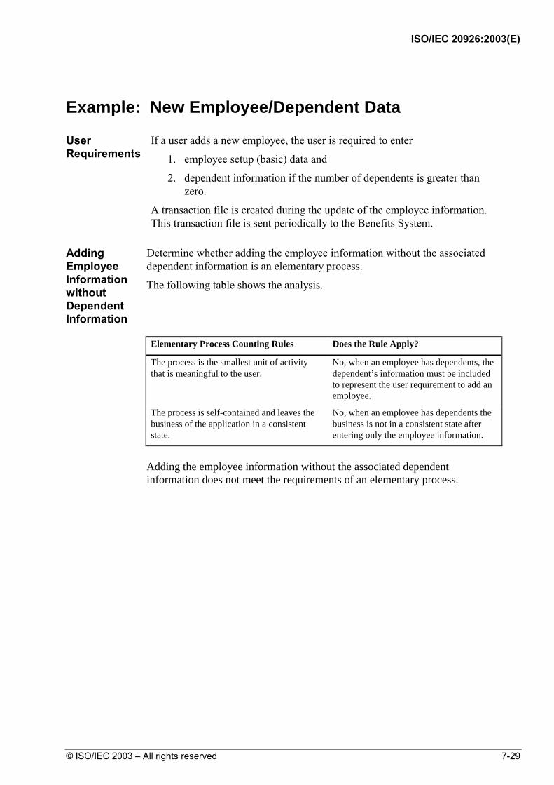
ISO/IEC 20926:2003(E)
© ISO/IEC 2003 – All rights reserved 7-29
Example: New Employee/Dependent Data
User Requirements
If a user adds a new employee, the user is required to enter
1. employee setup (basic) data and
2. dependent information if the number of dependents is greater than zero.
A transaction file is created during the update of the employee information. This transaction file is sent periodically to the Benefits System.
Adding Employee Information without Dependent Information
Determine whether adding the employee information without the associated dependent information is an elementary process.
The following table shows the analysis.
Elementary Process Counting Rules Does the Rule Apply?
The process is the smallest unit of activity that is meaningful to the user.
No, when an employee has dependents, the dependent’s information must be included to represent the user requirement to add an employee.
The process is self-contained and leaves the business of the application in a consistent state.
No, when an employee has dependents the business is not in a consistent state after entering only the employee information.
Adding the employee information without the associated dependent information does not meet the requirements of an elementary process.

ISO/IEC 20926:2003(E)
7-30 © ISO/IEC 2003 – All rights reserved
Adding only Dependent Information
Determine whether adding only the dependent information without the employee information is an elementary process.
The following table shows the analysis.
Elementary Process Counting Rules Does the Rule Apply?
The process is the smallest unit of activity that is meaningful to the user.
No, this activity is apparently not meaningful to the user because it can not be executed independent of maintaining an employee.
The process is self-contained and leaves the business of the application in a consistent state.
Not Applicable.
Adding the dependent information without the associated employee information does not meet the requirements of an elementary process.
Adding an Employee with Dependent Information
For an employee who has dependents, determine whether adding the employee information with the associated dependent information is an elementary process.
The following table shows the analysis.
Elementary Process Counting Rules Does the Rule Apply?
The process is the smallest unit of activity that is meaningful to the user.
Yes, together employee and dependent information are used to add an employee to the HR system.
The process is self-contained and leaves the business of the application in a consistent state.
Yes, this process is meaningful by itself and all necessary information is added to the HR application so the business is left in a consistent state (update file can be created and sent to Benefits system).
Adding the employee information with the dependent information meets the requirements of an elementary process.
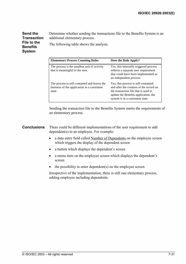
ISO/IEC 20926:2003(E)
© ISO/IEC 2003 – All rights reserved 7-31
Send the Transaction File to the Benefits System
Determine whether sending the transactions file to the Benefits System is an additional elementary process.
The following table shows the analysis.
Elementary Process Counting Rules Does the Rule Apply?
The process is the smallest unit of activity that is meaningful to the user.
Yes, this internally triggered process reflects a separate user requirement that could have been implemented as an independent process.
The process is self-contained and leaves the business of the application in a consistent state.
Yes, this process is self-contained, and after the creation of the record on the transaction file that is used to update the Benefits application, the system is in a consistent state.
Sending the transaction file to the Benefits System meets the requirements of an elementary process.
Conclusions There could be different implementations of the user requirement to add
dependent(s) to an employee. For example:
• a data entry field called Number of Dependents on the employee screen which triggers the display of the dependent screen
• a button which displays the dependent’s screen
• a menu item on the employee screen which displays the dependent’s screen
• the possibility to enter dependent(s) on the employee screen
Irrespective of the implementation, there is still one elementary process, adding employee including dependents.

ISO/IEC 20926:2003(E)
7-32 © ISO/IEC 2003 – All rights reserved
Example: Print a Check/Mark It Paid
User Requirements
Print a check and, as a result, mark the account as paid. All data printed on the check is already stored in the check file.
The following diagram shows the data flow for this example.
Print check
Check ILF Check Number Check Amount Recipient Account Paid Indicator ...
Marking the Account as Paid
Determine whether marking the account as paid is an elementary process.
The following table shows the analysis.
Elementary Process Counting Rules Does the Rule Apply?
The process is the smallest unit of activity that is meaningful to the user.
No, together the printing and marking the field are required to print the check.
The process is self-contained and leaves the business of the application in a consistent state.
No, the process is not meaningful by itself and both are required.
Marking the account as paid does not meet the requirements for an elementary process.

ISO/IEC 20926:2003(E)
© ISO/IEC 2003 – All rights reserved 7-33
Printing the Check and Marking the Account as Paid
Determine whether printing the check and marking the account as paid is an elementary process.
The following table shows the analysis.
Elementary Process Counting Rules Does the Rule Apply?
The process is the smallest unit of activity that is meaningful to the user.
Yes, together the printing and marking the field are required to print the check.
The process is self-contained and leaves the business of the application in a consistent state.
Yes, the process is meaningful by itself and both printing and marking are required to complete the process.
Printing the check and marking the account as paid meets the requirements for an Elementary Process.
The user requirement is to print the check. Marking the field Account Paid Indicator is part of the printing process. Printing and marking together are the smallest unit of activity that is meaningful to the user. The entire process is self-contained and leaves the business of the application in a consistent state.
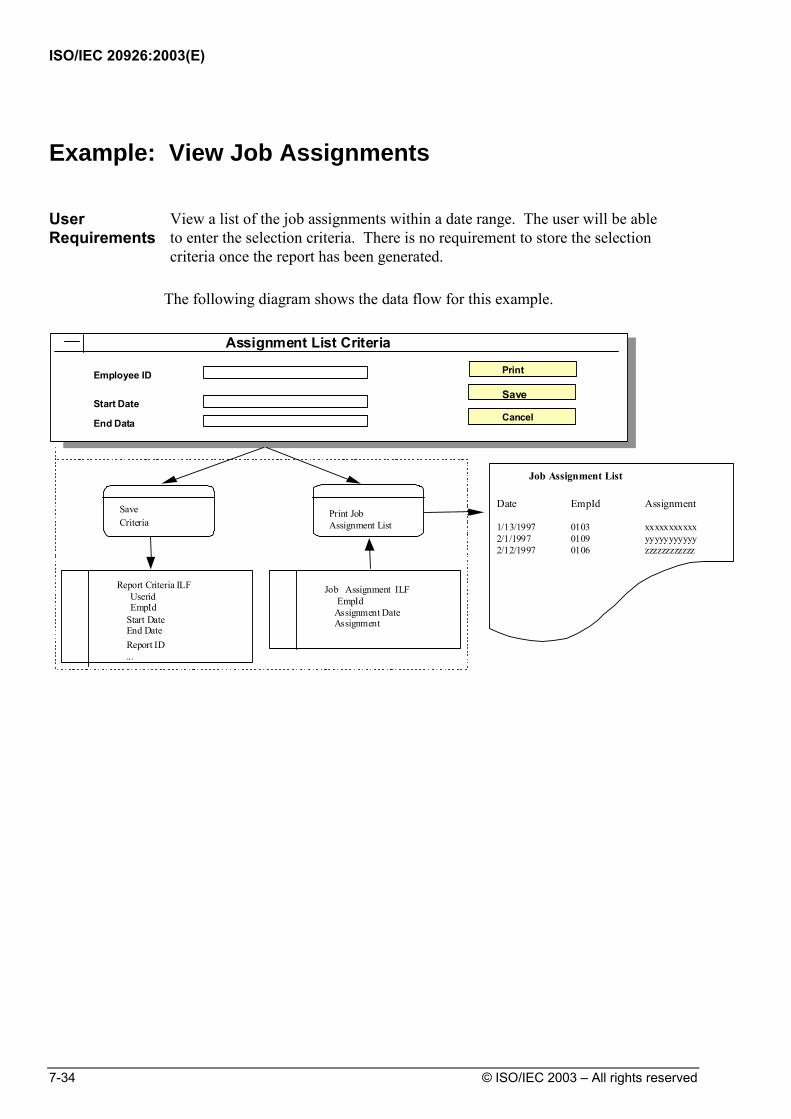
ISO/IEC 20926:2003(E)
7-34 © ISO/IEC 2003 – All rights reserved
Example: View Job Assignments
User Requirements
View a list of the job assignments within a date range. The user will be able to enter the selection criteria. There is no requirement to store the selection criteria once the report has been generated.
The following diagram shows the data flow for this example.
Save Criteria
Assignment List Criteria
Employee ID
Start Date
End Data
Cancel
Save
Job Assignment List
Date EmpId Assignment
1/13/1997 0103 xxxxxxxxxxx2/1/1997 0109 yyyyyyyyyyy2/12/1997 0106 zzzzzzzzzzzz
Job Assignment ILF EmpId Assignment Date Assignment
Report Criteria ILF Userid EmpId Start Date End Date
...
Print JobAssignment List
Report ID
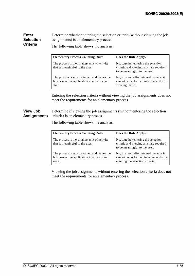
ISO/IEC 20926:2003(E)
© ISO/IEC 2003 – All rights reserved 7-35
Enter Selection Criteria
Determine whether entering the selection criteria (without viewing the job assignments) is an elementary process.
The following table shows the analysis.
Elementary Process Counting Rules Does the Rule Apply?
The process is the smallest unit of activity that is meaningful to the user.
No, together entering the selection criteria and viewing a list are required to be meaningful to the user.
The process is self-contained and leaves the business of the application in a consistent state.
No, it is not self-contained because it cannot be performed independently of viewing the list.
Entering the selection criteria without viewing the job assignments does not meet the requirements for an elementary process.
View Job Assignments
Determine if viewing the job assignments (without entering the selection criteria) is an elementary process.
The following table shows the analysis.
Elementary Process Counting Rules Does the Rule Apply?
The process is the smallest unit of activity that is meaningful to the user.
No, together entering the selection criteria and viewing a list are required to be meaningful to the user.
The process is self-contained and leaves the business of the application in a consistent state.
No, it is not self-contained because it cannot be performed independently by entering the selection criteria.
Viewing the job assignments without entering the selection criteria does not meet the requirements for an elementary process.

ISO/IEC 20926:2003(E)
7-36 © ISO/IEC 2003 – All rights reserved
Enter Selection Criteria and View Job Assignments
Determine whether entering the selection criteria and viewing the job assignments is an elementary process.
The following table shows the analysis.
Elementary Process Counting Rules Does the Rule Apply?
The process is the smallest unit of activity that is meaningful to the user.
Yes, together entering the selection criteria and viewing a list are required to be meaningful to the user.
The process is self-contained and leaves the business of the application in a consistent state.
Yes, it is self-contained because both have to be performed to leave the business in a consistent state.
Entering the selection criteria and viewing the job assignments meets the criteria for an elementary process.
Control information is the input side of an EO or EQ. The request specifying what and/or how data is to be retrieved or generated is part of the elementary process to provide the user data and is not an elementary process itself.
Entering the selection criterion is not the smallest unit of activity that is meaningful to the user. It is not self-contained because it cannot be performed independently of producing the report. Entering the selection criteria and generating the report together comprise the smallest unit of activity that is meaningful to the user, is self-contained and leaves the business in a consistent state.
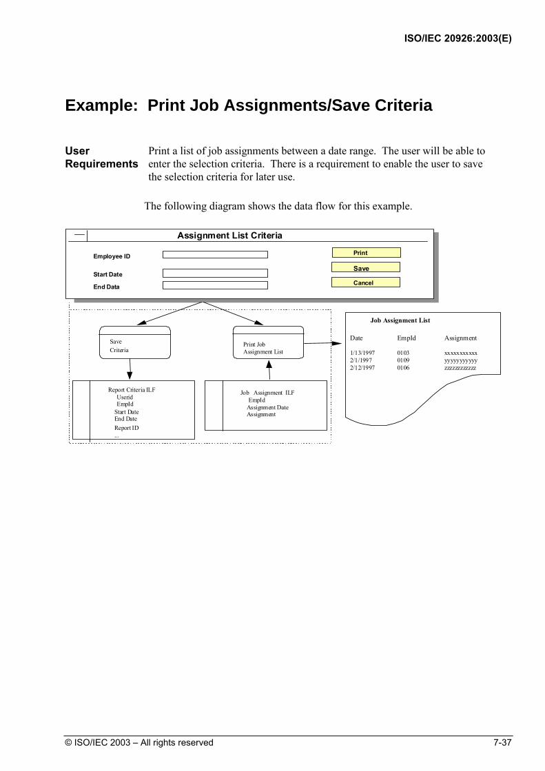
ISO/IEC 20926:2003(E)
© ISO/IEC 2003 – All rights reserved 7-37
Example: Print Job Assignments/Save Criteria
User Requirements
Print a list of job assignments between a date range. The user will be able to enter the selection criteria. There is a requirement to enable the user to save the selection criteria for later use.
The following diagram shows the data flow for this example.
Save Criteria
Assignment List Criteria
Employee ID
Start Date
End Data
Cancel
Save
Job Assignment List
Date EmpId Assignment
1/13/1997 0103 xxxxxxxxxxx2/1/1997 0109 yyyyyyyyyyy2/12/1997 0106 zzzzzzzzzzzz
Job Assignment ILF EmpId Assignment Date Assignment
Report Criteria ILF Userid EmpId Start Date End Date
...
Print JobAssignment List
Report ID
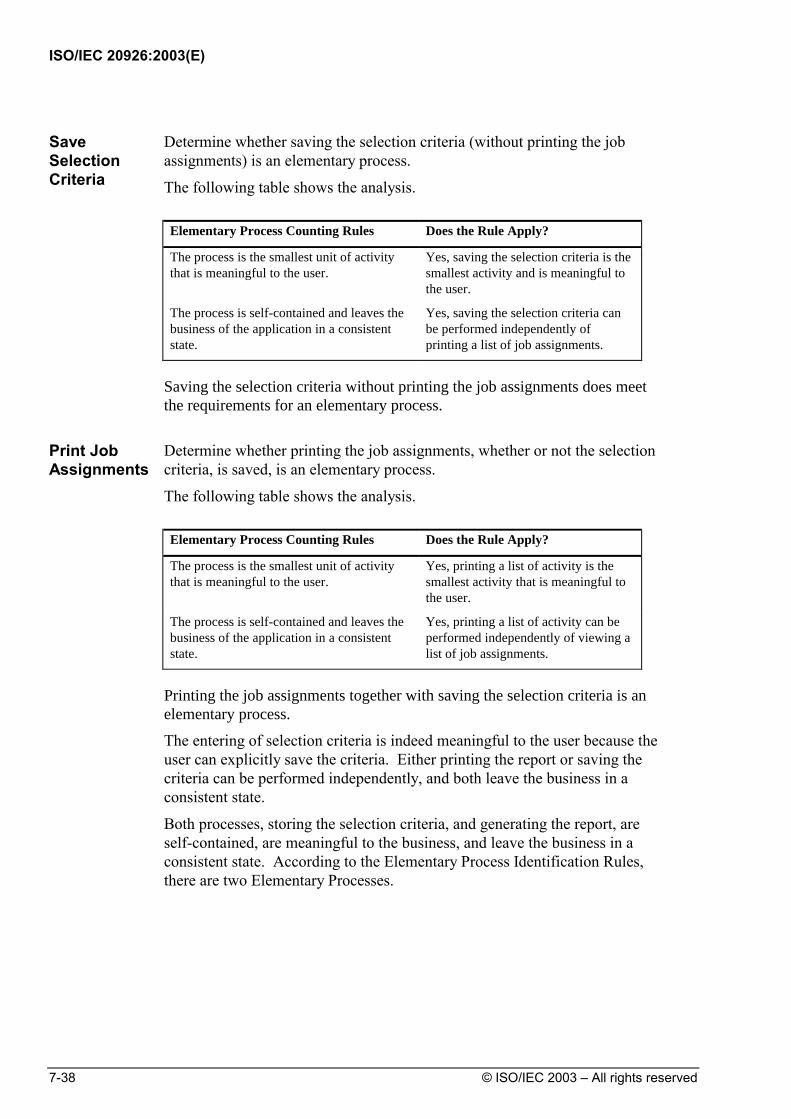
ISO/IEC 20926:2003(E)
7-38 © ISO/IEC 2003 – All rights reserved
Save Selection Criteria
Determine whether saving the selection criteria (without printing the job assignments) is an elementary process.
The following table shows the analysis.
Elementary Process Counting Rules Does the Rule Apply?
The process is the smallest unit of activity that is meaningful to the user.
Yes, saving the selection criteria is the smallest activity and is meaningful to the user.
The process is self-contained and leaves the business of the application in a consistent state.
Yes, saving the selection criteria can be performed independently of printing a list of job assignments.
Saving the selection criteria without printing the job assignments does meet the requirements for an elementary process.
Print Job Assignments
Determine whether printing the job assignments, whether or not the selection criteria, is saved, is an elementary process.
The following table shows the analysis.
Elementary Process Counting Rules Does the Rule Apply?
The process is the smallest unit of activity that is meaningful to the user.
Yes, printing a list of activity is the smallest activity that is meaningful to the user.
The process is self-contained and leaves the business of the application in a consistent state.
Yes, printing a list of activity can be performed independently of viewing a list of job assignments.
Printing the job assignments together with saving the selection criteria is an elementary process.
The entering of selection criteria is indeed meaningful to the user because the user can explicitly save the criteria. Either printing the report or saving the criteria can be performed independently, and both leave the business in a consistent state.
Both processes, storing the selection criteria, and generating the report, are self-contained, are meaningful to the business, and leave the business in a consistent state. According to the Elementary Process Identification Rules, there are two Elementary Processes.

ISO/IEC 20926:2003(E)
© ISO/IEC 2003 – All rights reserved 7-39
Example: Employee/Interview Information
User Requirements
When adding a new employee, in addition to the employee’s personal data (i.e., Social Security Number, surname, address, etc.), the employee’s interview details must be entered. The interview information includes the interviewer’s name, the interview date, and the interviewer’s comments.
The following diagram shows the data flow for this example.
CreateEmployee
Add InterviewDetails
Employee ILF SSN Surname Address ... Interviewer Name Interview Date Interviewer Comments
Create EmployeeCreate
Cancel
Employee SSN
Surname
Address
Add Interview DetailsAdd
Cancel
Interviewer Name
Interview Date
Interviewer Comments

ISO/IEC 20926:2003(E)
7-40 © ISO/IEC 2003 – All rights reserved
Entering the Employee’s Personal Data
Determine whether entering only the employee’s personal information is an Elementary Process.
The following table shows the analysis.
Elementary Process Counting Rules Does the Rule Apply?
The process is the smallest unit of activity that is meaningful to the user.
No, together entering the employee’s personal data and entering employee’s interview details are required to be meaningful to the user.
The process is self-contained and leaves the business of the application in a consistent state.
No, it is not self-contained because it cannot be performed independently of entering the employee’s interview detail.
Entering the employee’s personal information without entering the interview details does not meet the requirements for an elementary process.
Entering Employee’s Interview Details
Determine if entering only the employee’s interview details is an elementary process.
The following table shows the analysis.
Elementary Process Counting Rules Does the Rule Apply?
The process is the smallest unit of activity that is meaningful to the user.
No, together entering the employee’s personal data and entering employee’s interview details are required to be meaningful to the user.
The process is self-contained and leaves the business of the application in a consistent state.
No, it is not self-contained because it cannot be performed independently of entering the employee’s personal data.
Entering the employee’s interview details without the personal data does not meet the requirements for an elementary process.
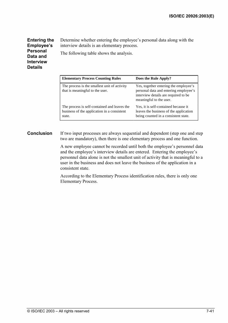
ISO/IEC 20926:2003(E)
© ISO/IEC 2003 – All rights reserved 7-41
Entering the Employee’s Personal Data and Interview Details
Determine whether entering the employee’s personal data along with the interview details is an elementary process.
The following table shows the analysis.
Elementary Process Counting Rules Does the Rule Apply?
The process is the smallest unit of activity that is meaningful to the user.
Yes, together entering the employee’s personal data and entering employee’s interview details are required to be meaningful to the user.
The process is self-contained and leaves the business of the application in a consistent state.
Yes, it is self-contained because it leaves the business of the application being counted in a consistent state.
Conclusion If two input processes are always sequential and dependent (step one and step
two are mandatory), then there is one elementary process and one function.
A new employee cannot be recorded until both the employee’s personnel data and the employee’s interview details are entered. Entering the employee’s personnel data alone is not the smallest unit of activity that is meaningful to a user in the business and does not leave the business of the application in a consistent state.
According to the Elementary Process identification rules, there is only one Elementary Process.

ISO/IEC 20926:2003(E)
7-42 © ISO/IEC 2003 – All rights reserved
Example: Employee/License Information
User Requirements
When adding a new employee, the employee data is entered for Social Security Number, name, address, and whether or not the employee has a driver’s license. If the employee does have a driver’s license, a secondary process must be completed to record the employee’s driver’s license number, classification(s), and expiration date.
The following diagram shows the data flow for this example.
Employee ILF SSN Surname Address Driver’s License License Number Classification Expiration Date
Driver’sLicense?Create
EmployeeAdd LicenseInformation
Create EmployeeCreate
CancelEmployee SSN
Surname
Address
Add License InformationReturn
Cancel
Driver’s License
License Number
Classification
Expiration Date
Driver’s License
No
Yes
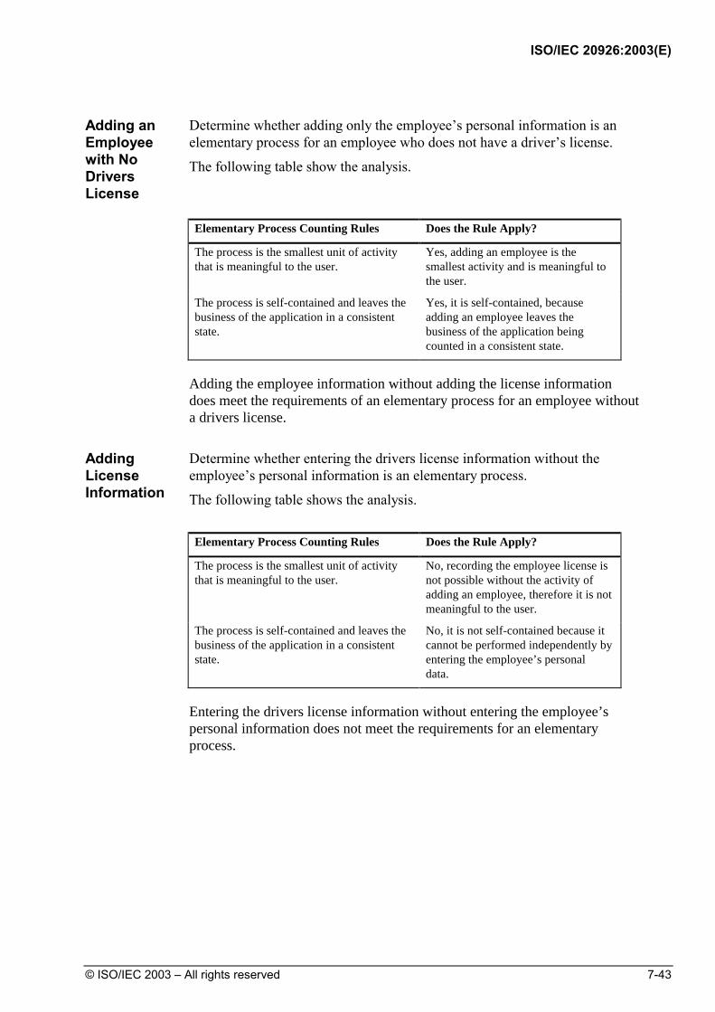
ISO/IEC 20926:2003(E)
© ISO/IEC 2003 – All rights reserved 7-43
Adding an Employee with No Drivers License
Determine whether adding only the employee’s personal information is an elementary process for an employee who does not have a driver’s license.
The following table show the analysis.
Elementary Process Counting Rules Does the Rule Apply?
The process is the smallest unit of activity that is meaningful to the user.
Yes, adding an employee is the smallest activity and is meaningful to the user.
The process is self-contained and leaves the business of the application in a consistent state.
Yes, it is self-contained, because adding an employee leaves the business of the application being counted in a consistent state.
Adding the employee information without adding the license information does meet the requirements of an elementary process for an employee without a drivers license.
Adding License Information
Determine whether entering the drivers license information without the employee’s personal information is an elementary process.
The following table shows the analysis.
Elementary Process Counting Rules Does the Rule Apply?
The process is the smallest unit of activity that is meaningful to the user.
No, recording the employee license is not possible without the activity of adding an employee, therefore it is not meaningful to the user.
The process is self-contained and leaves the business of the application in a consistent state.
No, it is not self-contained because it cannot be performed independently by entering the employee’s personal data.
Entering the drivers license information without entering the employee’s personal information does not meet the requirements for an elementary process.

ISO/IEC 20926:2003(E)
7-44 © ISO/IEC 2003 – All rights reserved
Adding Employee and License Information
Determine whether entering an employee’s personal information together with the associated license information is an elementary process.
The following table shows the analysis.
Elementary Process Counting Rules Does the Rule Apply?
The process is the smallest unit of activity that is meaningful to the user.
Yes, adding an employee and recording the employee license is the smallest activity and is meaningful to the user.
The process is self-contained and leaves the business of the application in a consistent state.
Yes, it is self-contained, because adding an employee and recording the employee license leaves the business of the application being counted in a consistent state.
Conclusion If two input processes are always sequential and dependent, but the second
process is optional (but is mandatory if it applies), then there is one elementary process.
There is one Elementary Process, Adding Employee. If an employee does not have a license the step “Add License Information” is not relevant. If an employee does have a driver’s license, a secondary screen must be completed to complete the Elementary Process and leave the business of the application in a consistent state

ISO/IEC 20926:2003(E)
© ISO/IEC 2003 – All rights reserved 7-45
EI/EO/EQ Counting Examples Introduction This section uses a Human Resources (HR) application to illustrate
procedures used to count transactional functions. In addition to this section, examples are in the Case Studies included in the complementary IFPUG documentation.
Caution: The examples in this section and throughout the manual have two purposes:
1. To illustrate how the function point counting rules are applied for a given set of user requirements.
2. To enable you to practice using the counting procedures.
Each counter must:
• Analyze the specific user requirements that apply for each project or application being counted, and
• Count based on those requirements.

ISO/IEC 20926:2003(E)
7-46 © ISO/IEC 2003 – All rights reserved
Contents This section explains the organization of the examples and includes detailed
examples for each transactional function.
Topic See Page
Organization of the Counting Examples 7-47
EI Counting Examples 7-52
EO Counting Examples 7-89
EQ Counting Examples 7-123

ISO/IEC 20926:2003(E)
© ISO/IEC 2003 – All rights reserved 7-47
Organization of the Counting Examples
This section explains how the examples are presented.
Outline of the Organization The following list outlines the sequence of information in the detailed
examples.
For each example:
• The EIs, EOs, and EQs are identified.
• The FTRs and DETs that make up the functional complexity are counted.
For all the examples combined:
• Items that were counted and not counted as EIs, EOs, or EQs are summarized.
• The complexity and contribution to the unadjusted function point count are determined for all identified EIs, EOs, or EQs.
Diagram of the Organization The following diagram illustrates the organization of the examples.
ExampleIdentify EQs
Count FTRs/DETs
ExampleIdentify EOs
Count FTRs/DETs
Example Identify EIs
Count FTRs /DETs SummaryAll EIs/EOs/EQs IdentifiedAll FTRs/DETS Counted
Complexity/ Contribution
All EIs / EOs / EQs Identified

ISO/IEC 20926:2003(E)
7-48 © ISO/IEC 2003 – All rights reserved
Count for Each Example Each example includes the following components:
• Basis for the count • Tables applying the counting rules

ISO/IEC 20926:2003(E)
© ISO/IEC 2003 – All rights reserved 7-49
Diagram of Components The following diagram illustrates the components for each example and the
flow of information.

ISO/IEC 20926:2003(E)
7-50 © ISO/IEC 2003 – All rights reserved
Basis for the Count
The basis for the count begins each example. As shown in the diagram of components, the count may be based on the following components included in the examples:
• User requirements
• Data and process models
• Windows, screens, or reports
Note: All components in the diagram are not included in all examples. In some examples, the requirements stand alone as the basis for the count. Other examples include a data or process model, windows, screens, and reports.
Rules Tables
The analysis to identify functions is presented in a table that lists the counting rules for the function type. The rules are applied to the components that make up the basis for the count. The analysis is explained in the table in the column "Does the Rule Apply?"
Note: If all the rules apply, the example is counted as an EI, EO, or EQ.
The next tables show the rules and explanation for types that make up the complexity for each function type identified.
Summary of EIs/EOs/EQs Identified After all the rules are applied for each example, a summary section lists what
was counted and what was not counted.
Complexity and Contribution for All EIs/EOs/EQs The last section in the examples is the calculation of the complexity and
contribution to the unadjusted function point count.
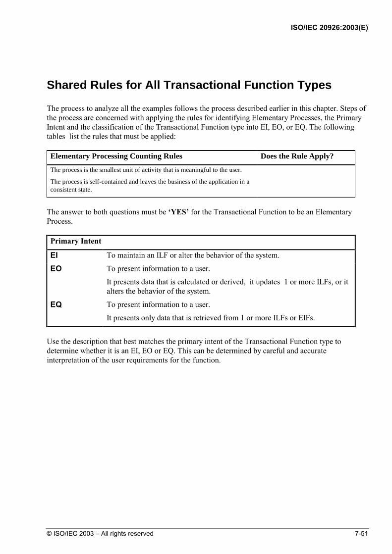
ISO/IEC 20926:2003(E)
© ISO/IEC 2003 – All rights reserved 7-51
Shared Rules for All Transactional Function Types
The process to analyze all the examples follows the process described earlier in this chapter. Steps of the process are concerned with applying the rules for identifying Elementary Processes, the Primary Intent and the classification of the Transactional Function type into EI, EO, or EQ. The following tables list the rules that must be applied: Elementary Processing Counting Rules Does the Rule Apply?
The process is the smallest unit of activity that is meaningful to the user.
The process is self-contained and leaves the business of the application in a consistent state.
The answer to both questions must be ‘YES’ for the Transactional Function to be an Elementary Process. Primary Intent
EI To maintain an ILF or alter the behavior of the system.
EO To present information to a user.
It presents data that is calculated or derived, it updates 1 or more ILFs, or it alters the behavior of the system.
EQ To present information to a user.
It presents only data that is retrieved from 1 or more ILFs or EIFs.
Use the description that best matches the primary intent of the Transactional Function type to determine whether it is an EI, EO or EQ. This can be determined by careful and accurate interpretation of the user requirements for the function.

ISO/IEC 20926:2003(E)
7-52 © ISO/IEC 2003 – All rights reserved
EI Counting Examples Introduction This section uses a Human Resources (HR) application to illustrate
procedures to count external inputs. In addition to this section, examples are in the Case Studies.
Contents This section includes the following examples:
Topic See Page Summary Descriptions of EI Counting Examples 7-53
Example: Control Information 7-54
Example: Screen Input 7-58
Example: Batch with Multiple EIs and Duplicate EIs 7-62
Example: Correcting Suspended Transactions 7-66
Example: EI with Multiple File Types Referenced 7-70
Example: Data Conversion 7-74
Example: Referencing Data from Another Application 7-77
Example: EI with Screen Output - 1 7-79
Example: EI with Screen Output - 2 7-82
Summary of EIs, FTRs and DETs Counted 7-86
External Input Complexity and Contribution 7-87

ISO/IEC 20926:2003(E)
© ISO/IEC 2003 – All rights reserved 7-53
Summary Descriptions of EI Counting Examples
The examples for external inputs are listed and described in the following
table.
Example Summary Description Page
Control Information This example looks at control information used for reporting.
7-54
Screen Input This example illustrates counting an online add transaction via a screen.
7-58
Batch with Multiple EIs and Duplicate EIs
This example shows how to count a transaction file with multiple types or formatted record types.
7-62
Correcting Suspended Transactions
This example illustrates counting making corrections to jobs suspended to a file during batch processing of adding or changing jobs.
7-66
EI with Multiple File Types Referenced
This example illustrates using a data flow diagram to count an external input that references multiple files.
7-70
Data Conversion This example shows how to count the process of converting a group of data to a new format with additional data elements.
7-74
Referencing Data from Another Application
This example looks at why an external interface file (discussed in Chapter 6) is not counted as an external input.
7-77
EI with Screen Output –1 This example illustrates an EI with a calculated field that is displayed.
7-79
EI with Screen Output –2 This example illustrates an EI with a calculated field and embedded EQs.
7-82

ISO/IEC 20926:2003(E)
7-54 © ISO/IEC 2003 – All rights reserved
Example: Control Information
User Requirements
The user requires the ability to control how and when assignment reports are printed. The following list shows the specific user requirements for generating the report:
1. Control the following aspects of report processing:
• Sort sequence
• Printer port
• Whether or not to generate a microfiche copy
• Whether or not to generate a paper copy
2. Save the job assignment reporting controls.
3. Make and save changes.
4. Send a message to confirm that the controls for the assignment reports have been added or changed, and that the report is being generated.
Note: This example shows only the requirement to add the group of assignment report control information. The Case Studies illustrate counting the entire user requirement.
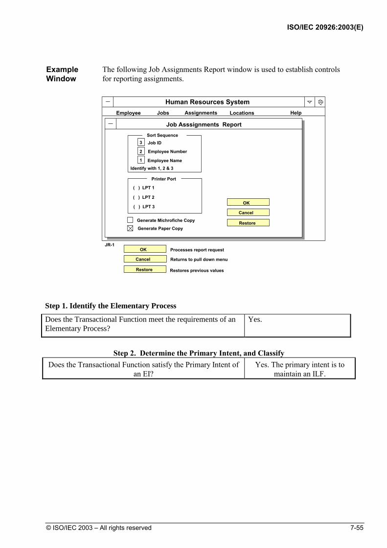
ISO/IEC 20926:2003(E)
© ISO/IEC 2003 – All rights reserved 7-55
Example Window
The following Job Assignments Report window is used to establish controls for reporting assignments.
Human Resources System
Jobs Assignments Locations HelpEmployee
Job Asssignments ReportSort Sequence
Printer Port
( ) LPT 1
( ) LPT 2
( ) LPT 3
Generate Michrofiche Copy
Generate Paper Copy
OK
Cancel
Restore
OK
Cancel
Restore
JR-1Processes report request
Returns to pull down menu
Restores previous values
3
2
1
Job ID
Employee Number
Employee NameIdentify with 1, 2 & 3
Step 1. Identify the Elementary Process
Does the Transactional Function meet the requirements of an Elementary Process?
Yes.
Step 2. Determine the Primary Intent, and Classify
Does the Transactional Function satisfy the Primary Intent of an EI?
Yes. The primary intent is to maintain an ILF.

ISO/IEC 20926:2003(E)
7-56 © ISO/IEC 2003 – All rights reserved
Step 3. Validate against the EI Counting Rules EI Counting Rules Does the Rule Apply?
The data or control information is received from outside the application boundary.
Yes.
At least one ILF is maintained if the data entering the boundary is not control information that alters the behavior of the system.
The data entering the boundary will eventually be used as control data. It is business data stored on the Report Control ILF.
For the identified process, one of the following three statements must apply:
• Processing logic is unique from the processing logic performed by other external inputs for the application.
Yes. No other EI has been identified that performs this function.
• The set of data elements identified is different from the sets identified for other external inputs for the application.
Not applicable.
• The ILFs or EIFs referenced are different from the files referenced by other external inputs in the application.
Not applicable.
Conclusion: There is 1 EI.
Step 4. Determine the Complexity
FTR Counting Rules Does the Rule Apply?
Count an FTR for each ILF maintained. The report control ILF is maintained.
Count an FTR for each ILF or EIF read during the processing of the external input.
The report control ILF is read.
Count only one FTR for each ILF that is both maintained and read.
The report control ILF is maintained and read. It is counted only once.
Conclusion: The FTR count is 1.

ISO/IEC 20926:2003(E)
© ISO/IEC 2003 – All rights reserved 7-57
DET Counting Rules Does the Rule Apply?
Count one DET for each user recognizable, non-repeated field that enters or exits the application boundary and is required to complete the external input.
Sort Sequence, Printer Port, Output Format.
Do not count fields that are retrieved or derived by the system and stored on an ILF during the elementary process if the fields did not cross the application boundary.
Not applicable.
Count one DET for the capability to send a system response message outside the application boundary to indicate an error occurred during processing, confirm that processing is complete or verify that processing should continue.
User message.
Count one DET for the ability to specify an action to be taken even if there are multiple methods for invoking the same logical process.
OK button.
Conclusion: The DET count is 5.
Complexity 1 FTR and 5 DETs. Complexity is Low
Step 5. Determine the Contribution Contribution is 1 Low Complexity EI 3 FP

ISO/IEC 20926:2003(E)
7-58 © ISO/IEC 2003 – All rights reserved
Example: Screen Input
User Requirements
The user requires the ability to
• Add job information online
• Generate an error message and highlight incorrect fields so that the error may be corrected online
• Save job information added
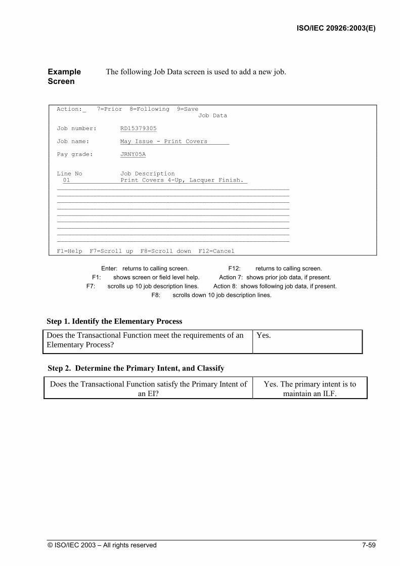
ISO/IEC 20926:2003(E)
© ISO/IEC 2003 – All rights reserved 7-59
Example Screen
The following Job Data screen is used to add a new job.
Action:_ 7=Prior 8=Following 9=Save
Job Data Job number: RD15379305 Job name: May Issue - Print Covers Pay grade: JRNY05A Line No Job Description 01 Print Covers 4-Up, Lacquer Finish. ________________________________________________________________ ________________________________________________________________ ________________________________________________________________ ________________________________________________________________ ________________________________________________________________ ________________________________________________________________ ________________________________________________________________ ________________________________________________________________ ________________________________________________________________ F1=Help F7=Scroll up F8=Scroll down F12=Cancel
Enter: returns to calling screen. F12: returns to calling screen.
F1: shows screen or field level help. Action 7: shows prior job data, if present. F7: scrolls up 10 job description lines. Action 8: shows following job data, if present.
F8: scrolls down 10 job description lines.
Step 1. Identify the Elementary Process
Does the Transactional Function meet the requirements of an Elementary Process?
Yes.
Step 2. Determine the Primary Intent, and Classify
Does the Transactional Function satisfy the Primary Intent of an EI?
Yes. The primary intent is to maintain an ILF.

ISO/IEC 20926:2003(E)
7-60 © ISO/IEC 2003 – All rights reserved
Step 3. Validate against the EI Counting Rules
The following table shows the summary analysis of the user requirements using the EI data counting rules for the function, add a new job.
EI Counting Rules Does the Rule Apply?
The data or control information is received from outside the application boundary.
Yes. Job data is received across the boundary.
At least one ILF is maintained if the data entering the boundary is not control information that alters the behavior of the system.
Yes, the Job ILF is maintained.
For the identified process, one of the following three statements must apply:
• Processing logic is unique from the processing logic performed by other external inputs for the application.
Yes. The requirement to generate an error log makes the function unique.
• The set of data elements identified is different from the sets identified for other external inputs for the application.
Not applicable.
• The ILFs or EIFs referenced are different from the files referenced by other external inputs in the application.
Not applicable.
Conclusion: Adding a job is 1 EI.
Refer to the Case Studies to see how the change and delete requirements and associated screens are counted.

ISO/IEC 20926:2003(E)
© ISO/IEC 2003 – All rights reserved 7-61
Step 4. Determine the Complexity
FTR Counting Rules Does the Rule Apply?
Count an FTR for each ILF maintained. The job ILF is read and updated.
Count an FTR for each ILF or EIF read during the processing of the external input.
The job ILF is read.
Count only one FTR for each ILF that is both maintained and read.
The job ILF is maintained and read, but it is counted only once.
Conclusion: The FTR count is 1.
DET Counting Rules Does the Rule Apply?
Count one DET for each user recognizable, non-repeated field that enters or exits the application boundary and is required to complete the external input.
Job number, Job name, Job pay grade, Job description line number (Repeated), Job description line (Repeated).
Do not count fields that are retrieved or derived by the system and stored on an ILF during the elementary process if the fields did not cross the application boundary.
Not applicable.
Count one DET for the capability to send a system response message outside the application boundary to indicate an error occurred during processing, confirm that processing is complete or verify that processing should continue.
Error messages.
Count one DET for the ability to specify an action to be taken even if there are multiple methods for invoking the same logical process.
Add action.
Conclusion: The total DET count is 7.
Complexity 1 FTR and 7 DETs. Complexity is Low
Step 5. Determine the Contribution Contribution is 1 Low Complexity EI 3 FP

ISO/IEC 20926:2003(E)
7-62 © ISO/IEC 2003 – All rights reserved
Example: Batch with Multiple EIs and Duplicate EIs
User Requirements
The user requires the ability to
• Add and change job information in batch mode.
Note: The focus of this example is adding a job in batch mode. The previous example looked at the online mode. The Case Studies illustrate counting all user requirements for adding jobs in both online and batch modes.
Construction Requirements
It was decided that during the batch process, any jobs not successfully updated would error into a suspense file, which will be separately maintained. (See next example)
Record Layout
The following diagram shows the record layout for this example.
123456789101234567890123456789012345678901234567890123456789012345678901234567890 0 1 2 3 4 5 6 7 8 1 ADD01SRENGSENIOR ENGINEER INFORMATION SYSTEMS05 2 ADD02SRENG01STARTS AT PAY GRADE 05 3 ADD02SRENG02OTHER PAY GRADES:06 AND 07 4 CHG03STENG 04 5 CHG04STENG02OTHER PAY GRADES:05 AND 06 6 7 9 0 1 2 3 4 5 6 7 9 0 1 2 3 4

ISO/IEC 20926:2003(E)
© ISO/IEC 2003 – All rights reserved 7-63
Record Descriptions
The following table includes descriptions for each record type.
Record Position Description
01 1-3 Transaction type
4-5 Record type
6-10 Job number
11-45 Job name
46-47 Job pay grade
02 1-3 Transaction type
4-5 Record type
6-10 Job number
11-12 Description line number
13-41 Description line
Where Record Types are:
01 Add record for a new job
02 Add record for descriptions of a new job
Step 1. Identify the Elementary Process - Transaction Type 01
Does the Transactional Function meet the requirements of an Elementary Process?
No. A job without a description is not meaningful to the user.
Step 1. Identify the Elementary Process - Transaction Type 02
Does the Transactional Function meet the requirements of an Elementary Process?
No. A description cannot exist without the job it is describing. The data would be inconsistent.
Step 1. Identify the Elementary Process - Transaction Types 1 + 2
Does the Transactional Function meet the requirements of an Elementary Process?
Yes. Job and description are meaningful to the user.

ISO/IEC 20926:2003(E)
7-64 © ISO/IEC 2003 – All rights reserved
Step 2. Determine the Primary Intent, and Classify
Does the Transactional Function satisfy the Primary Intent of an EI?
Yes. The primary intent is to maintain an ILF.
Step 3. Validate against the EI Counting Rules
EI Counting Rules
Does the Rule Apply for combination of "Add Job Record 01 and Add Job Record 02?"
The data or control information is received from outside the application boundary.
Yes.
At least one ILF is maintained if the data entering the boundary is not control information that alters the behavior of the system.
Job, Suspended Job.
For the identified process, one of the following three statements must apply:
• Processing logic is unique from the processing logic performed by other external inputs for the application.
Yes. This function is unique from the on-line case, however different validation rules apply, and there is a requirement concerning suspended jobs in the event of a failure.
• The set of data elements identified is different from the sets identified for other external inputs for the application.
Not applicable.
• The ILFs or EIFs referenced are different from the files referenced by other external inputs in the application.
Not applicable.
Conclusion: The combined Transaction Type 01 + 02 is 1 EI.
Step 4. Determine the Complexity
FTR Counting Rules Does the Rule Apply?
Count an FTR for each ILF maintained. Job, Suspended Job.
Count an FTR for each ILF or EIF read during the processing of the external input.
Job.
Count only one FTR for each ILF that is both maintained and read.
The job ILF is maintained and read, but it is counted only once.
Conclusion: The FTR count is 2.

ISO/IEC 20926:2003(E)
© ISO/IEC 2003 – All rights reserved 7-65
DET Counting Rules Does the Rule Apply?
Count one DET for each user recognizable, non-repeated field that enters or exits the application boundary and is required to complete the external input.
Job number, Job name, Job pay grade, Job description line number (Repeated), Job description line (Repeated).
Record Type is physical therefore not counted.
Do not count fields that are retrieved or derived by the system and stored on an ILF during the elementary process if the fields did not cross the application boundary.
Not applicable.
Count one DET for the capability to send a system response message outside the application boundary to indicate an error occurred during processing, confirm that processing is complete or verify that processing should continue.
Not applicable. Errors are recorded in a suspense file.
Count one DET for the ability to specify an action to be taken even if there are multiple methods for invoking the same logical process.
Transaction type.
Conclusion: The DET count for adding a job is 6.
Complexity 2 FTRs and 6 DETs. Complexity is Average
Step 5. Determine the Contribution Contribution is 1 Average Complexity EI 4 FP

ISO/IEC 20926:2003(E)
7-66 © ISO/IEC 2003 – All rights reserved
Example: Correcting Suspended Transactions
User Requirements
It was decided that during the batch process that any jobs not successfully updated would error into a suspense. The user requires a screen to access and edit the transactions that are incorrect.
Note: The focus of this example is only the requirement to correct suspended transactions. The Case Studies illustrate counting the entire user requirement.
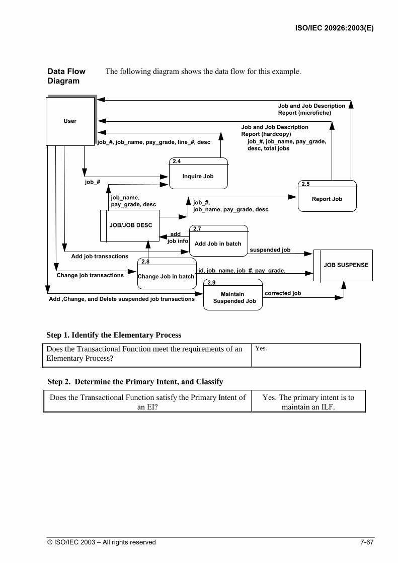
ISO/IEC 20926:2003(E)
© ISO/IEC 2003 – All rights reserved 7-67
Data Flow Diagram
The following diagram shows the data flow for this example.
suspended job
User
JOB/JOB DESC
MaintainSuspended Job
job_#
job_#, job_name, pay_grade, line_#, desc
job_name,pay_grade, desc job_#,
job_name, pay_grade, desc
Job and Job DescriptionReport (microfiche)
Job and Job DescriptionReport (hardcopy)
add job info
Add job transactions
Add ,Change, and Delete suspended job transactionscorrected job
Inquire Job
2.4
Report Job
2.5
Add Job in batch
2.7
2.9
job_#, job_name, pay_grade,desc, total jobs
JOB SUSPENSEChange job transactions Change Job in batch
2.8id, job_name, job_#, pay_grade,
Step 1. Identify the Elementary Process
Does the Transactional Function meet the requirements of an Elementary Process?
Yes.
Step 2. Determine the Primary Intent, and Classify
Does the Transactional Function satisfy the Primary Intent of an EI?
Yes. The primary intent is to maintain an ILF.

ISO/IEC 20926:2003(E)
7-68 © ISO/IEC 2003 – All rights reserved
Step 3. Validate against the EI Counting Rules
EI Counting Rules Does the Rule Apply for the Suspense File?
The data or control information is received from outside the application boundary.
Yes. Data for correcting the transaction in error is received across the boundary.
At least one ILF is maintained if the data entering the boundary is not control information that alters the behavior of the system.
Yes. The suspense file is updated.
For the identified process, one of the following three statements must apply:
• Processing logic is unique from the processing logic performed by other external inputs for the application.
Yes. No other EI has been identified that performs this function.
• The set of data elements identified is different from the sets identified for other external inputs for the application.
Not applicable.
• The ILFs or EIFs referenced are different from the files referenced by other external inputs in the application.
Not applicable.
Conclusion: There is 1 EI.
Step 4. Determine the Complexity
FTR Counting Rules Does the Rule Apply?
Count an FTR for each ILF maintained. Job Suspense.
Count an FTR for each ILF or EIF read during the processing of the external input.
Job Suspense.
Count only one FTR for each ILF that is both maintained and read.
Job Suspense is maintained and referenced, but it is counted only once.
Conclusion: FTR count is 1.

ISO/IEC 20926:2003(E)
© ISO/IEC 2003 – All rights reserved 7-69
DET Counting Rules Does the Rule Apply?
Count one DET for each user recognizable, non-repeated field that enters or exits the application boundary and is required to complete the external input.
Transaction type, Job number, Job name, Job pay grade, Job description line number (Repeated), Job description line (Repeated).
The Record Type is physical and is, therefore, not counted. All other fields are user recognizable.
Do not count fields that are retrieved or derived by the system and stored on an ILF during the elementary process if the fields did not cross the application boundary.
Not applicable.
Count one DET for the capability to send a system response message outside the application boundary to indicate an error occurred during processing, confirm that processing is complete or verify that processing should continue.
There are no messages.
Count one DET for the ability to specify an action to be taken even if there are multiple methods for invoking the same logical process.
Enter key.
Conclusion: The DET count is 7. Note that the transaction type is spaced within Job
Suspense and may be maintained by the user.
Complexity 1 FTR and 7 DETs. Complexity is Low
Step 5. Determine the Contribution Contribution is 1 Low Complexity EI 3 FP

ISO/IEC 20926:2003(E)
7-70 © ISO/IEC 2003 – All rights reserved
Example: EI with Multiple File Types Referenced
User Requirements
The user requires the ability to add job assignments.
Note: The focus of this example is only the requirement to add job assignments. The Case Studies illustrate counting the entire user requirement.
Example Window
The following diagram shows an example of the window to add job assignments.
Human Resources SystemJobs Assignments Locations HelpEmployee
Employee Assignments
AE-4
Job Assignment Data
Previous
Next
Mark J Manship
345-67-8901
Main Plant UFPCA
Job Number
Date
Salary
Performance Rating
RD15379305
03/27/93
17.28
Satisfactory
Previous
Next
Shows prior job record for employee, if present
Shows following job record for employee, if present
May Issue - Print Covers

ISO/IEC 20926:2003(E)
© ISO/IEC 2003 – All rights reserved 7-71
Data Flow Diagram
The following diagram shows the data flow for the job assignment process.
UserUser
3.1
AddJob Assgnmt
3.2ChangeJob Assgnmt JOB ASSGNMT
3.3
DeleteJob Assgnmt
3.4InquireJob Assgnmt
JOBASSGNMT
3.5
ReportJob Assgnmt
JOB
ssn,job_#,effective_date,perf_rating, salary
ssn, job_#, effective_date, perf_rating, salary
ssn, old job_#,new job_#,effective_date, perf_rating, salary
effective_date,perf_rating, salary
ssn, job_#
ssn, job_#
ssn, name, job_#, job_name, effective_date,salary, perf_rating
job assgnmt info
effective_date,salary, perf_rating
name
ssn, nameEMPL
job namejob_#,job_name
Job Assignments Report (hardcopy)job_#, job_name, ssn, name,total_employees_for_job
JOB
EMPL
name
namejob_name
job_name
Legend:
User or Application
Data Stored
Process
Flow of Data
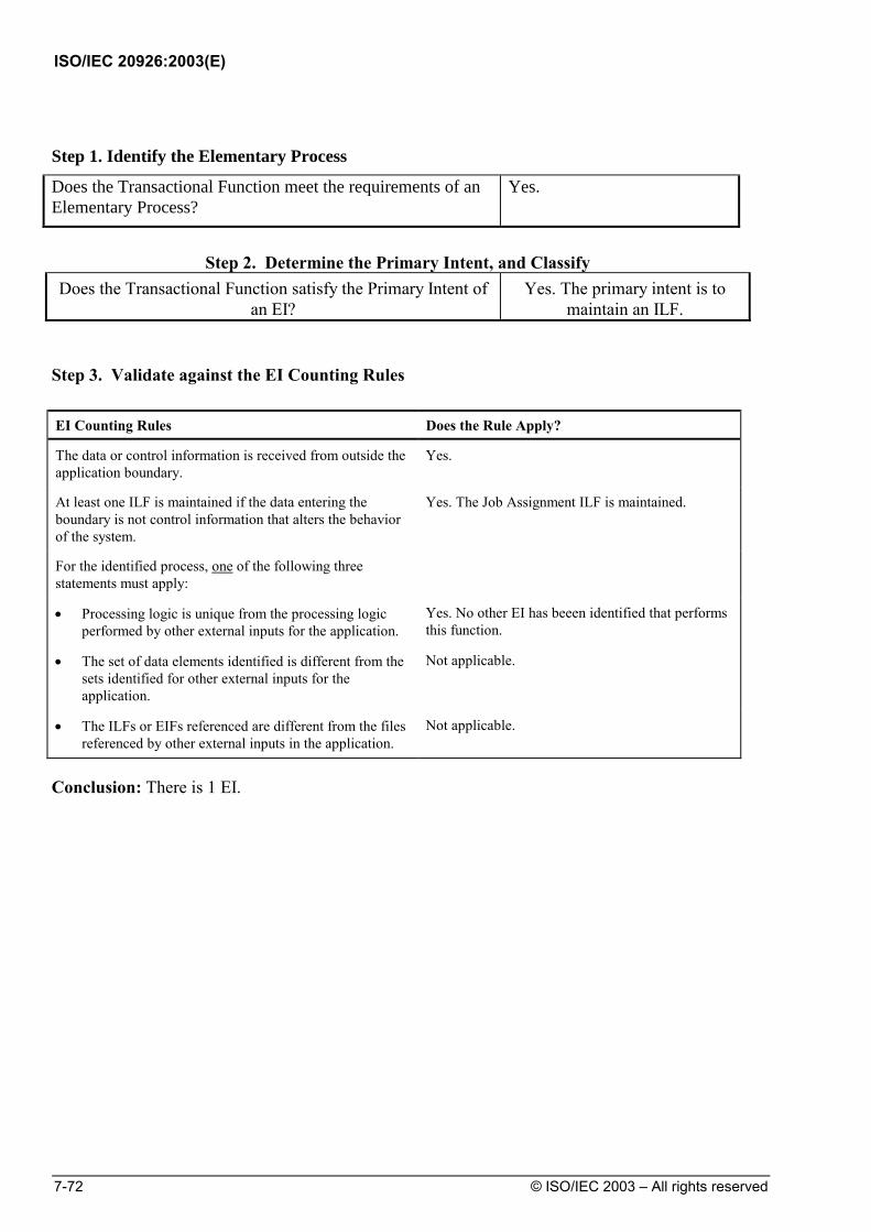
ISO/IEC 20926:2003(E)
7-72 © ISO/IEC 2003 – All rights reserved
Step 1. Identify the Elementary Process
Does the Transactional Function meet the requirements of an Elementary Process?
Yes.
Step 2. Determine the Primary Intent, and Classify
Does the Transactional Function satisfy the Primary Intent of an EI?
Yes. The primary intent is to maintain an ILF.
Step 3. Validate against the EI Counting Rules EI Counting Rules Does the Rule Apply?
The data or control information is received from outside the application boundary.
Yes.
At least one ILF is maintained if the data entering the boundary is not control information that alters the behavior of the system.
Yes. The Job Assignment ILF is maintained.
For the identified process, one of the following three statements must apply:
• Processing logic is unique from the processing logic performed by other external inputs for the application.
Yes. No other EI has beeen identified that performs this function.
• The set of data elements identified is different from the sets identified for other external inputs for the application.
Not applicable.
• The ILFs or EIFs referenced are different from the files referenced by other external inputs in the application.
Not applicable.
Conclusion: There is 1 EI.
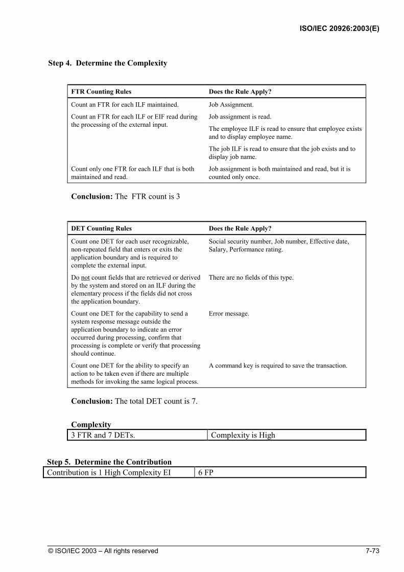
ISO/IEC 20926:2003(E)
© ISO/IEC 2003 – All rights reserved 7-73
Step 4. Determine the Complexity
FTR Counting Rules Does the Rule Apply?
Count an FTR for each ILF maintained. Job Assignment.
Count an FTR for each ILF or EIF read during the processing of the external input.
Job assignment is read.
The employee ILF is read to ensure that employee exists and to display employee name.
The job ILF is read to ensure that the job exists and to display job name.
Count only one FTR for each ILF that is both maintained and read.
Job assignment is both maintained and read, but it is counted only once.
Conclusion: The FTR count is 3
DET Counting Rules Does the Rule Apply?
Count one DET for each user recognizable, non-repeated field that enters or exits the application boundary and is required to complete the external input.
Social security number, Job number, Effective date, Salary, Performance rating.
Do not count fields that are retrieved or derived by the system and stored on an ILF during the elementary process if the fields did not cross the application boundary.
There are no fields of this type.
Count one DET for the capability to send a system response message outside the application boundary to indicate an error occurred during processing, confirm that processing is complete or verify that processing should continue.
Error message.
Count one DET for the ability to specify an action to be taken even if there are multiple methods for invoking the same logical process.
A command key is required to save the transaction.
Conclusion: The total DET count is 7.
Complexity 3 FTR and 7 DETs. Complexity is High
Step 5. Determine the Contribution Contribution is 1 High Complexity EI 6 FP

ISO/IEC 20926:2003(E)
7-74 © ISO/IEC 2003 – All rights reserved
Example: Data Conversion
User Requirements
The user has purchased a new HR application package. The user requires the ability to migrate existing employee information to the new application.
The old system did not let the user maintain employee dependent's information. The dependent's information is initialized when existing employees are migrated to the new application.
Note: Chapter 9 explains how this one-time data conversion is included in the project function point counts but excluded from the application counts.
Data Diagrams
The following diagram shows the data for the old and new applications.
Old
HR Application
EMPLOYEE
SALARIED_EMPL
HOURLY_EMPL
New HR Application
EMPLOYEE
SALARIED_EMPL
HOURLY_EMPL
DEPENDENT
Step 1. Identify the Elementary Process
Does the Transactional Function meet the requirements of an Elementary Process?
Yes.
Step 2. Determine the Primary Intent, and Classify
Does the Transactional Function satisfy the Primary Intent of an EI?
Yes. The primary intent is to maintain an ILF.

ISO/IEC 20926:2003(E)
© ISO/IEC 2003 – All rights reserved 7-75
Step 3. Validate against the EI Counting Rules EI Counting Rules Does the Rule Apply?
The data or control information is received from outside the application boundary.
Yes. Data from the employee file of the old HR application crosses the boundary.
At least one ILF is maintained if the data entering the boundary is not control information that alters the behavior of the system.
Yes. The employee ILF is maintained.
For the identified process, one of the following three statements must apply:
• Processing logic is unique from the processing logic performed by other external inputs for the application.
Yes. No other EI has beeen identified that performs this function using data from this source.
• The set of data elements identified is different from the sets identified for other external inputs for the application.
Not applicable.
• The ILFs or EIFs referenced are different from the files referenced by other external inputs in the application.
Not applicable.
Conclusion: There is 1 EI.
Step 4. Determine the Complexity
FTR Counting Rules Does the Rule Apply?
Count an FTR for each ILF maintained. The employee ILF is maintained.
Count an FTR for each ILF or EIF read during the processing of the external input.
The employee ILF is read.
Count only one FTR for each ILF that is both maintained and read.
The employee ILF is maintained and read, but it is counted only once.
Conclusion: The FTR count is 1.

ISO/IEC 20926:2003(E)
7-76 © ISO/IEC 2003 – All rights reserved
DET Counting Rules Does the Rule Apply?
Count one DET for each user recognizable, non-repeated field that enters or exits the application boundary and is required to complete the external input.
Name, Social security number, Number of dependents, Type code, Supervisory level, Standard hourly rate, Collective bargaining unit number, Dependent social security number, Dependent name, Dependent birth date, Location name.
Do not count fields that are retrieved or derived by the system and stored on an ILF during the elementary process if the fields did not cross the application boundary.
There are no fields of this type.
Count one DET for the capability to send a system response message outside the application boundary to indicate an error occurred during processing, confirm that processing is complete or verify that processing should continue.
Not applicable.
Count one DET for the ability to specify an action to be taken even if there are multiple methods for invoking the same logical process.
Not applicable.
Conclusion: The DET count is 11.
Complexity 1 FTR and 11 DETs. Complexity is Low
Step 5. Determine the Contribution Contribution is 1 Low Complexity EI 3 FP

ISO/IEC 20926:2003(E)
© ISO/IEC 2003 – All rights reserved 7-77
Example: Referencing Data from Another Application
User Requirements
The user requires the Human Resources application to provide the following capabilities:
• All hourly employees must be paid in United States dollars.
• When adding or changing employee information, the Human Resources application must access the Currency application to retrieve a conversion rate. After retrieving the conversion rate, the HR application converts the employee's local standard hourly rate to a U.S. hourly rate using the following calculation:
Standard Hourly Rate
Conversion Rate= U.S. Dollar Hourly Rate
The following diagram shows the relationship for this example.
Currency Application HR Application
SALARIED_EMPLHOURLY_EMPL
EMPLOYEE
DEPENDENT
CONVERSIONRATE
Legend:
Mandatory One-to-Many Relationship
Optional One-to-Many Relationship
Attribute Entity Type
Entity Type
Entity Subtype

ISO/IEC 20926:2003(E)
7-78 © ISO/IEC 2003 – All rights reserved
Conversion Information
The conversion information includes
CURRENCY
• Conversion_Rate_To_Base_Currency
• Country
Step 1. Identify the Elementary Process
Does the Transactional Function meet the requirements of an Elementary Process?
No. Referencing the data is only meaningful when assciated with adding an employee.
Conclusion: There is not an EI for the retrieval of conversion onformation. Refer to the EIF counting examples in Chapter 6 to see why conversion information may be counted as an EIF.

ISO/IEC 20926:2003(E)
© ISO/IEC 2003 – All rights reserved 7-79
Example: EI with Screen Output - 1
User Requirements
The user requires the ability to save a sales transaction for a customer. The cost of each item is to be shown, and the transaction total must be displayed for review before the information is saved.
Example Screen
The following sales transaction screen is a simplification to illustrate how output fields are counted. The user enters the customer name and transaction date. As each item and quantity required is entered, the system calculates and displays the costs as shown.
Sales Transaction Customer Name: __________________________________________ Transaction Date: ________ Item Qty at Item Cost Item Total Cost __________________________ _____ $____.__ $____.__ __________________________ _____ $____.__ $____.__ __________________________ _____ $____.__ $____.__ __________________________ _____ $____.__ $____.__ __________________________ _____ $____.__ $____.__ __________________________ _____ $____.__ $____.__ Sub Total $____.__ Sales Tax $____.__ Total $____.__ F1=Save
Step 1. Identify the Elementary Process
Does the Transactional Function meet the requirements of an Elementary Process?
Yes.
Step 2. Determine the Primary Intent, and Classify
Does the Transactional Function satisfy the Primary Intent of an EI?
Yes. The primary intent is to maintain an ILF.

ISO/IEC 20926:2003(E)
7-80 © ISO/IEC 2003 – All rights reserved
Step 3. Validate against the EI Counting Rules
EI Counting Rules Does the Rule Apply?
The data or control information is received from outside the application boundary.
Yes. Transaction data is received across the boundary.
At least one ILF is maintained if the data entering the boundary is not control information that alters the behavior of the system.
Yes, the sales transaction ILF is maintained.
For the identified process, one of the following three statements must apply:
• Processing logic is unique from the processing logic performed by other external inputs for the application.
Yes. No other EI has been identified that performs this function.
• The set of data elements identified is different from the sets identified for other external inputs for the application.
Not applicable.
• The ILFs or EIFs referenced are different from the files referenced by other external inputs in the application.
Not applicable.
Conclusion: There is one EI
Step 4. Determine the Complexity
FTR Counting Rules Does the Rule Apply?
Count an FTR for each ILF maintained. The sales transaction ILF is maintained.
Count an FTR for each ILF or EIF read during the processing of the external input.
The sales item ILF is referenced to recover the item cost.
Count only one FTR for each ILF that is both maintained and read.
Not applicable. The sales transaction ILF is maintained and read, but is counted only once.
Conclusion: The FTR count is 2.

ISO/IEC 20926:2003(E)
© ISO/IEC 2003 – All rights reserved 7-81
DET Counting Rules Does the Rule Apply?
Count one DET for each user recognizable, non-repeated field that enters or exits the application boundary and is required to complete the external input.
The following input DETs are counted: Customer name Transaction date Item (repeated) Quantity (repeated) The following output DETs are counted: Item cost (repeated) Item total cost (repeated) Transaction sub total Sales tax Transaction total total
Do not count fields that are retrieved or derived by the system and stored on an ILF during the elementary process if the fields did not cross the application boundary.
The output DETs are counted; although they are derived, they do cross the boundary.
Count one DET for the capability to send a system response message outside the application boundary to indicate an error occurred during processing, confirm that processing is complete or verify that processing should continue.
A message is returned in the event of an error.
Count one DET for the ability to specify an action to be taken even if there are multiple methods for invoking the same logical process.
Action: The F1 key.
Conclusion: The total DET count is 11.
Complexity 2 FTRs and 11 DETs. Complexity is Average
Step 5. Determine the Contribution Contribution is 1 Average Complexity EI 4 FP

ISO/IEC 20926:2003(E)
7-82 © ISO/IEC 2003 – All rights reserved
Example: EI with Screen Output - 2
User Requirements
The user requires the ability to assign a job to an employee. In order to select an employee and job, the user requires the ability to reference the employee and job files using 2 drop down lists. The employee list is required to show the employee number and name. The jobs list is required to show the job number and its description. The number of employees assigned to the job is to be displayed after the record is saved.
Example Screen
The following Job Assignment screen is a simplification to illustrate how output fields are counted. The user selects the employee from a drop down list showing the employee name and employee number. On selection, the system needs the employee number for the assignment. The user selects the job from a dropdown list showing the job number and its description. The system needs the job number for the assignment. When the assignment is saved, the systems determines the number of employees and displays it to the user.
It is clear that the inquiry on jobs and employees are two separate elementary processes (EQs); They are not analyzed here.
Save
Employee Number Job Number
Total Number of Employees assigned to this Job
1290 James, R.W0100 Apply Lacquer
12900100
3
Employees Jobs Assignments Locations Help
Human Resources System
Assignment Date 12/12/1998
Job Assignment
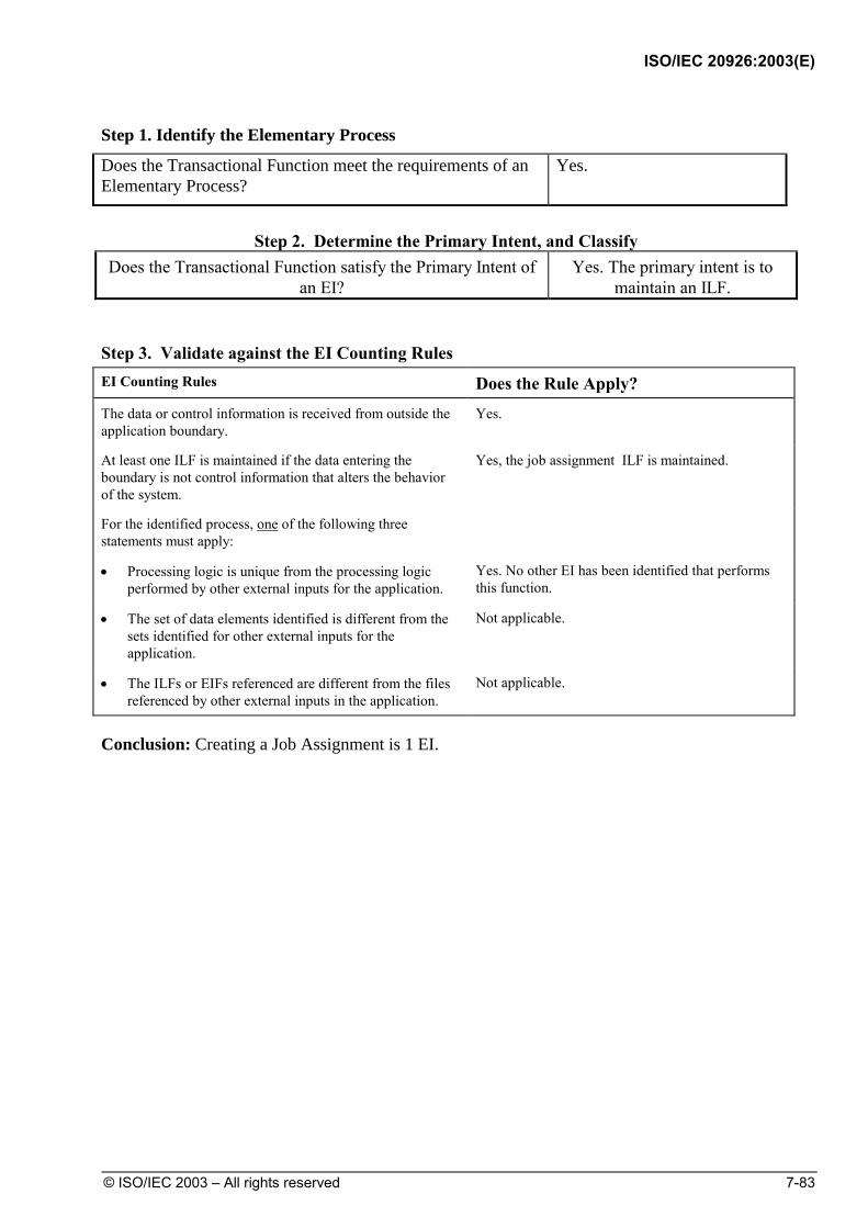
ISO/IEC 20926:2003(E)
© ISO/IEC 2003 – All rights reserved 7-83
Step 1. Identify the Elementary Process
Does the Transactional Function meet the requirements of an Elementary Process?
Yes.
Step 2. Determine the Primary Intent, and Classify
Does the Transactional Function satisfy the Primary Intent of an EI?
Yes. The primary intent is to maintain an ILF.
Step 3. Validate against the EI Counting Rules EI Counting Rules Does the Rule Apply? The data or control information is received from outside the application boundary.
Yes.
At least one ILF is maintained if the data entering the boundary is not control information that alters the behavior of the system.
Yes, the job assignment ILF is maintained.
For the identified process, one of the following three statements must apply:
• Processing logic is unique from the processing logic performed by other external inputs for the application.
Yes. No other EI has been identified that performs this function.
• The set of data elements identified is different from the sets identified for other external inputs for the application.
Not applicable.
• The ILFs or EIFs referenced are different from the files referenced by other external inputs in the application.
Not applicable.
Conclusion: Creating a Job Assignment is 1 EI.
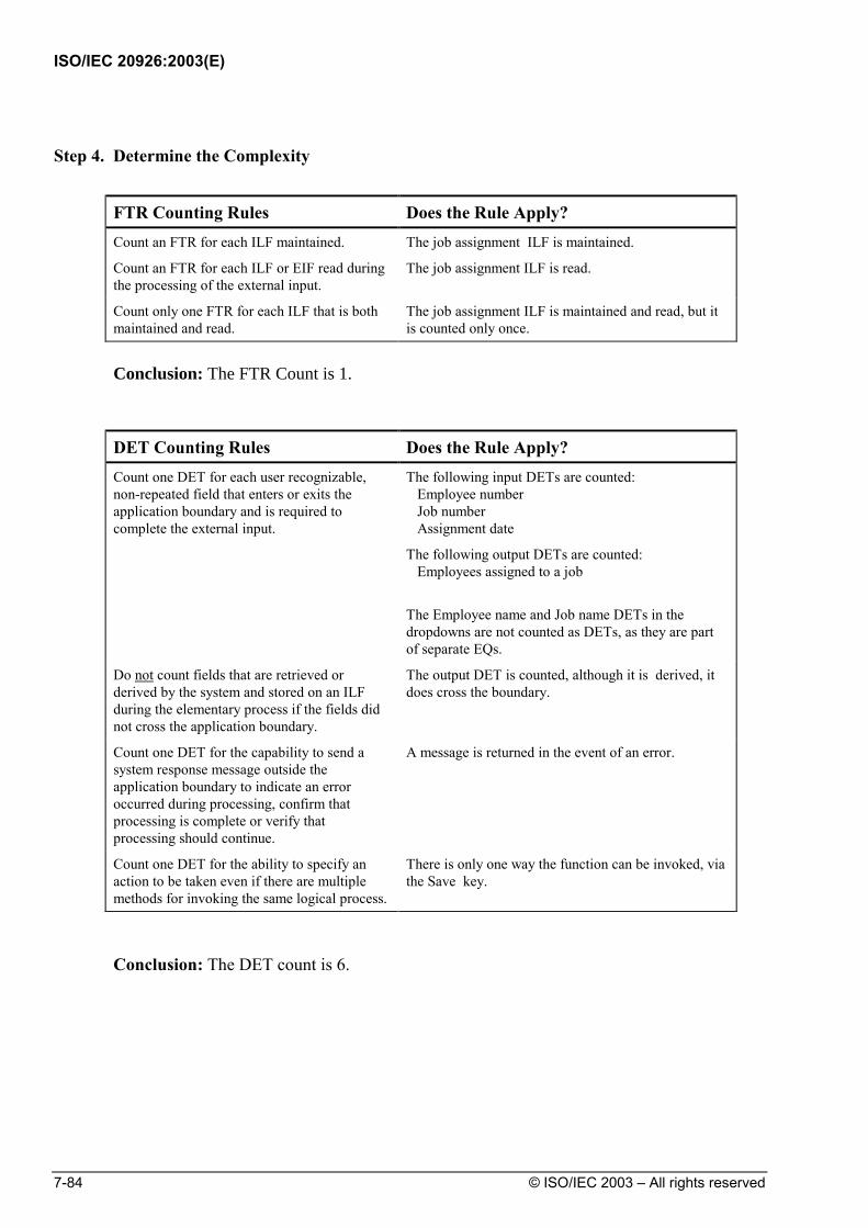
ISO/IEC 20926:2003(E)
7-84 © ISO/IEC 2003 – All rights reserved
Step 4. Determine the Complexity
FTR Counting Rules Does the Rule Apply? Count an FTR for each ILF maintained. The job assignment ILF is maintained.
Count an FTR for each ILF or EIF read during the processing of the external input.
The job assignment ILF is read.
Count only one FTR for each ILF that is both maintained and read.
The job assignment ILF is maintained and read, but it is counted only once.
Conclusion: The FTR Count is 1.
DET Counting Rules Does the Rule Apply? Count one DET for each user recognizable, non-repeated field that enters or exits the application boundary and is required to complete the external input.
The following input DETs are counted: Employee number Job number Assignment date
The following output DETs are counted: Employees assigned to a job
The Employee name and Job name DETs in the dropdowns are not counted as DETs, as they are part of separate EQs.
Do not count fields that are retrieved or derived by the system and stored on an ILF during the elementary process if the fields did not cross the application boundary.
The output DET is counted, although it is derived, it does cross the boundary.
Count one DET for the capability to send a system response message outside the application boundary to indicate an error occurred during processing, confirm that processing is complete or verify that processing should continue.
A message is returned in the event of an error.
Count one DET for the ability to specify an action to be taken even if there are multiple methods for invoking the same logical process.
There is only one way the function can be invoked, via the Save key.
Conclusion: The DET count is 6.

ISO/IEC 20926:2003(E)
© ISO/IEC 2003 – All rights reserved 7-85
Complexity 1 FTR and 6 DETs. Complexity is Low
Step 5. Determine the Contribution Contribution is 1 Low Complexity EI 3 FP

ISO/IEC 20926:2003(E)
7-86 © ISO/IEC 2003 – All rights reserved
Summary of EIs, FTRs and DETs Counted
This section gives a summary of EIs, FTRs, and DETs counted before calculating the complexity and contribution to the unadjusted function point count.
Summary of EIs Counted
The following table shows the EIs counted for the HR application. It also lists the data that was not counted.
EIs Counted Not Counted Control information Referencing data from another application. Add job information (screen input) Add job information (batch input)
Correct suspended transactions
Employee job assignment
Employee migration
EI with Screen Output -1 EI with Screen Output -2
Summary FTR/DET Count
The FTR and DET counts are recorded in the following table.
External Input FTRs DETs Assignment report information 1 5
Add job information (screen input) 1 7
Add job information (batch input)
Correct suspended transactions
2
1
6
7
Employee job assignment
Employee migration
3
1
7
11
EI with Screen Output -1 2 11
EI with Screen Output -2 1 6

ISO/IEC 20926:2003(E)
© ISO/IEC 2003 – All rights reserved 7-87
External Input Complexity and Contribution
This last section shows the final steps to determine EI complexity and
contribution to the unadjusted function point count.
The final steps are as follows:
1. Rate the EI complexity.
2. Translate the complexity to unadjusted function points.
3. Calculate the external inputs' contribution to the total unadjusted function point count.
Rate EI Complexity
The following complexity matrix rates the EI complexity.
1 to 4 DETs 5 to 15 DETs 16 or more DETs
0 to 1 FTR Low Low Average
2 FTRs Low Average High
3 or more FTRs Average High High
Legend:
FTR = File Type Referenced
DET = Data Element Type The following table shows the functional complexity for each EI.
External Input FTRs DETs Functional Complexity Assignment report information 1 5 Low
Add job information (screen input) 1 7 Low
Add job information (batch input) 2 6 Average
Correct suspended jobs 1 7 Low
Employee job assignment 3 7 High
Employee migration 1 11 Low
EI with Screen Output -1 2 11 Average
EI with Screen Output -2 1 6 Low
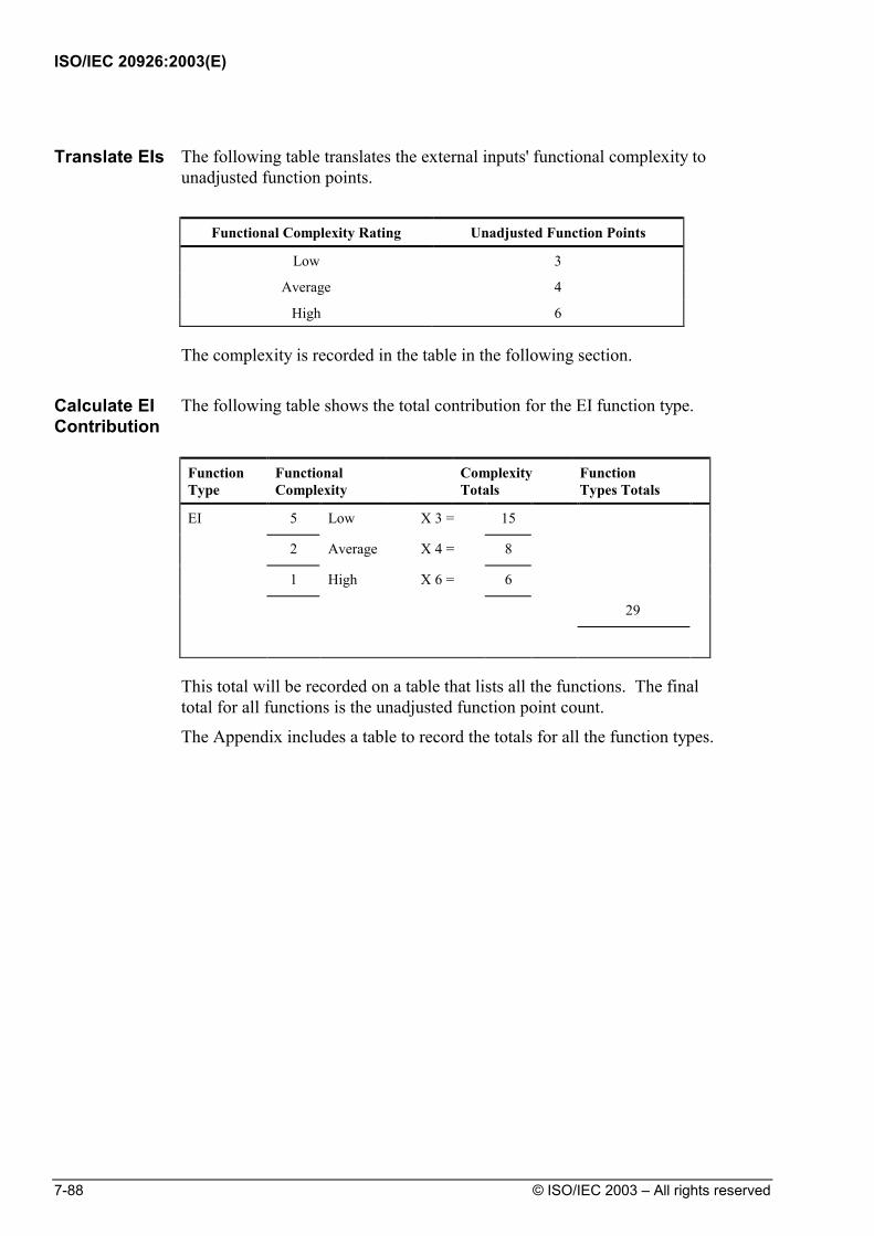
ISO/IEC 20926:2003(E)
7-88 © ISO/IEC 2003 – All rights reserved
Translate EIs The following table translates the external inputs' functional complexity to
unadjusted function points.
Functional Complexity Rating Unadjusted Function Points
Low 3
Average 4
High 6
The complexity is recorded in the table in the following section.
Calculate EI Contribution
The following table shows the total contribution for the EI function type.
Function Type
Functional Complexity
Complexity Totals
Function Types Totals
EI 5 Low X 3 = 15
2 Average X 4 = 8
1 High X 6 = 6
29
This total will be recorded on a table that lists all the functions. The final total for all functions is the unadjusted function point count.
The Appendix includes a table to record the totals for all the function types.
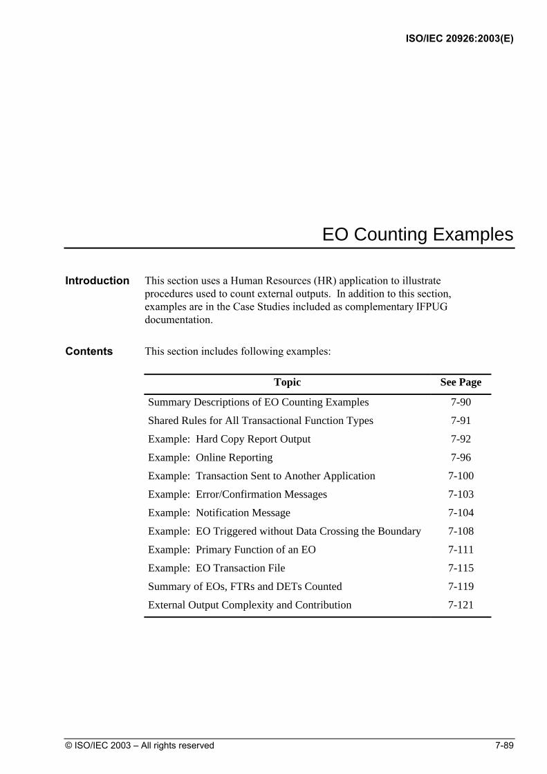
ISO/IEC 20926:2003(E)
© ISO/IEC 2003 – All rights reserved 7-89
EO Counting Examples Introduction This section uses a Human Resources (HR) application to illustrate
procedures used to count external outputs. In addition to this section, examples are in the Case Studies included as complementary IFPUG documentation.
Contents This section includes following examples:
Topic See Page
Summary Descriptions of EO Counting Examples 7-90
Shared Rules for All Transactional Function Types 7-91
Example: Hard Copy Report Output 7-92
Example: Online Reporting 7-96
Example: Transaction Sent to Another Application 7-100
Example: Error/Confirmation Messages 7-103
Example: Notification Message 7-104
Example: EO Triggered without Data Crossing the Boundary 7-108
Example: Primary Function of an EO 7-111
Example: EO Transaction File 7-115
Summary of EOs, FTRs and DETs Counted 7-119
External Output Complexity and Contribution 7-121

ISO/IEC 20926:2003(E)
7-90 © ISO/IEC 2003 – All rights reserved
Summary Descriptions of EO Counting Examples
The examples for EOs are described in the following table.
Example Summary Description Page
Hard Copy Report Output
This example looks at counting a hard copy report.
7-92
Online Reporting This example shows the count for an online report.
7-96
Transaction Sent to Another Application
This example illustrates a transaction generated by one application and sent to another application.
7-100
Error/Confirmation Messages
This example shows why error or confirmation messages are not counted as an external output.
7-103
Notification Message
This example illustrates how notification messages are counted.
7-104
EO Triggered without Data Crossing the Boundary
This example illustrates the concept that an EO can be triggered without data crossing the boundary.
7-108
Primary Function of an EO
This example illustrates that an EO can update a file.
7-111
EO Transaction File
This example illustrates the existence of calculations determines that the elementary process is an EO and not an EQ.
7-115

ISO/IEC 20926:2003(E)
© ISO/IEC 2003 – All rights reserved 7-91
Shared Rules for All Transactional Function Types
The process to analyze all the examples follows the process described earlier in this chapter. Steps of the process are concerned with applying the rules for identifying Elementary Processes, the Primary Intent and the classification of the Transactional Function type into EI, EO, or EQ. The following tables list the rules that must be applied: Elementary Process Counting Rules Does the Rule Apply?
The process is the smallest unit of activity that is meaningful to the user.
The process is self-contained and leaves the business of the application in a consistent state.
The answer to both questions must be ‘YES’ for the Transactional Function to be an Elementary Process. Primary Intent
EI To maintain an ILF or alter the behavior of the system.
EO To present information to a user.
It presents data that is calculated or derived, it updates 1 or more ILFs, or it alters the behavior of the system.
EQ To present information to a user.
It presents only data that is retrieved from 1 or more ILFs or EIFs.
Use the description that best matches the primary intent of the Transactional Function type to determine whether it is an EI, EO or EQ. This can be determined by careful and accurate interpretation of the user requirements for the function.
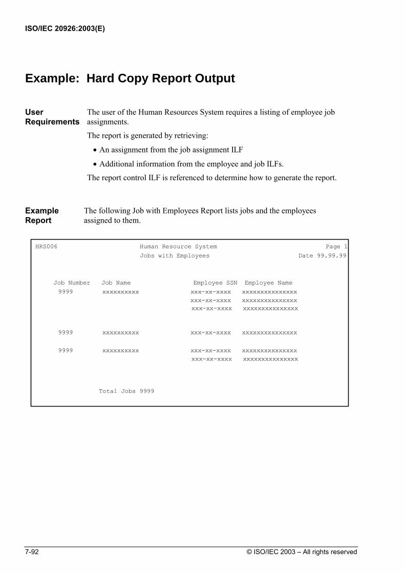
ISO/IEC 20926:2003(E)
7-92 © ISO/IEC 2003 – All rights reserved
Example: Hard Copy Report Output
User Requirements
The user of the Human Resources System requires a listing of employee job assignments.
The report is generated by retrieving:
• An assignment from the job assignment ILF
• Additional information from the employee and job ILFs.
The report control ILF is referenced to determine how to generate the report.
Example Report
The following Job with Employees Report lists jobs and the employees assigned to them.
HRS006 Human Resource System Page 1
Date 99.99.99
Job Number Job Name Employee SSN Employee Name9999 xxxxxxxxxx xxx-xx-xxxx xxxxxxxxxxxxxxx
xxx-xx-xxxx xxxxxxxxxxxxxxxxxx-xx-xxxx xxxxxxxxxxxxxxx
9999 xxxxxxxxxx xxx-xx-xxxx xxxxxxxxxxxxxxx
9999 xxxxxxxxxx xxx-xx-xxxx xxxxxxxxxxxxxxxxxx-xx-xxxx xxxxxxxxxxxxxxx
Total Jobs 9999
Jobs with Employees

ISO/IEC 20926:2003(E)
© ISO/IEC 2003 – All rights reserved 7-93
Step 1. Identify the Elementary Process
Does the Transactional Function meet the requirements of an Elementary Process?
Yes.
Step 2. Determine the Primary Intent, and Classify
Does the Transactional Function satisfy the Primary Intent of an EO?
Yes. The report contains a calculated field.
Step 3. Validate against the EO Counting Rules
EO Counting Rules Does the Rule Apply?
The function sends data or control information external to the application boundary.
Yes. The report data crosses the boundary.
For the identified process, one of the following three statements must apply:
• Processing logic is unique from the processing logic performed by other external outputs or external inquiries for the application.
Yes. No other EO has been identified that performs this function.
• The set of data elements identified is different from the sets identified for other external outputs and external inquiries in the application.
Not applicable.
• The ILFs or EIFs referenced are different from the files referenced by other external outputs and external inquiries in the application.
Not applicable.
For the identified process, one of the following three statements must apply:
• The processing logic of the elementary process contains at least one mathematical formula or calculation.
The total number of jobs is a calculated field.
• The processing logic of the elementary process maintains at least one ILF.
Not applicable.
• The processing logic of the elementary process creates derived data.
Not applicable.
Conclusion: There is 1 EO for the Jobs with Employees Report.

ISO/IEC 20926:2003(E)
7-94 © ISO/IEC 2003 – All rights reserved
Step 4. Determine the Complexity
FTR Counting Rule Does the Rule Apply?
Count one FTR for each ILF or EIF read during the processing of the elementary process.
Yes. The following ILFs are read: Employee Job Job assignment Report control.
Count one FTR for each ILF maintained during the processing of the elementary process.
No ILFs are maintained.
Count only one FTR for each ILF that is both maintained and read during the elementary process.
Not applicable.
Conclusion: The FTR count is 4.
DET Counting Rules Does the Rule Apply?
Count one DET for each user recognizable, non-repeated field that enters the application boundary and is required to specify when, what and/or how the data is to be retrieved or generated by the elementary process.
All fields are user recognizable.
Count one DET for each user recognizable, non-repeated field that exits the boundary.
Total jobs, Job number, Job name, Employee SSN, Employee name are reported. Count each only once.
If a DET both enters and exits the boundary, count it only once for the elementary process.
Not applicable.
Count one DET for the capability to send a system response message outside the application boundary to indicate an error occurred during processing, confirm that processing is complete or verify that processing should continue.
Not applicable.
Count one DET for the ability to specify an action to be taken even if there are multiple methods for invoking the same logical process.
Not applicable.
Do not count fields that are retrieved or derived by the system and stored on an ILF during the elementary process if the fields did not cross the application boundary.
Not applicable.
Do not count literals as DETs.
Do not count paging variables or system-generated stamps.
Conclusion: The DET count is 5.

ISO/IEC 20926:2003(E)
© ISO/IEC 2003 – All rights reserved 7-95
Complexity 4 FTRs and 5 DETs Complexity is Average
Step 5. Determine the Contribution Contribution is 1 Average Complexity EO
5 FP

ISO/IEC 20926:2003(E)
7-96 © ISO/IEC 2003 – All rights reserved
Example: Online Reporting
User Requirements
The user requires a report of employees in descending sequence by the duration of their current job assignments. This report is displayed online and contains derived data (for example, the job assignment duration).
Example Screen
The following Employees by Assignment Duration screen layout lists employees by duration.
. EMPLOYEES BY ASSIGNMENT DURATION Rows 1 to 18 of 1,316 MM/DD/YY Employee Employee Job Job Assignment SSN Name Number Name Duration xxx-xx-xxxx xxxxxxxxxx 9999 xxxxxxxxxx 99 mos. xxx-xx-xxxx xxxxxxxxxx 9999 xxxxxxxxxx 99 mos. Employees over 24 mos. 9999 Employees over 12 mos. 9999 F1=Help F7=Scroll up F8=Scroll down F16=End
Step 1. Identify the Elementary Process
Does the Transactional Function meet the requirements of an Elementary Process?
Yes.
Step 2. Determine the Primary Intent, and Classify
Does the Transactional Function satisfy the Primary Intent of an EO?
Yes. The report contains calculated data.
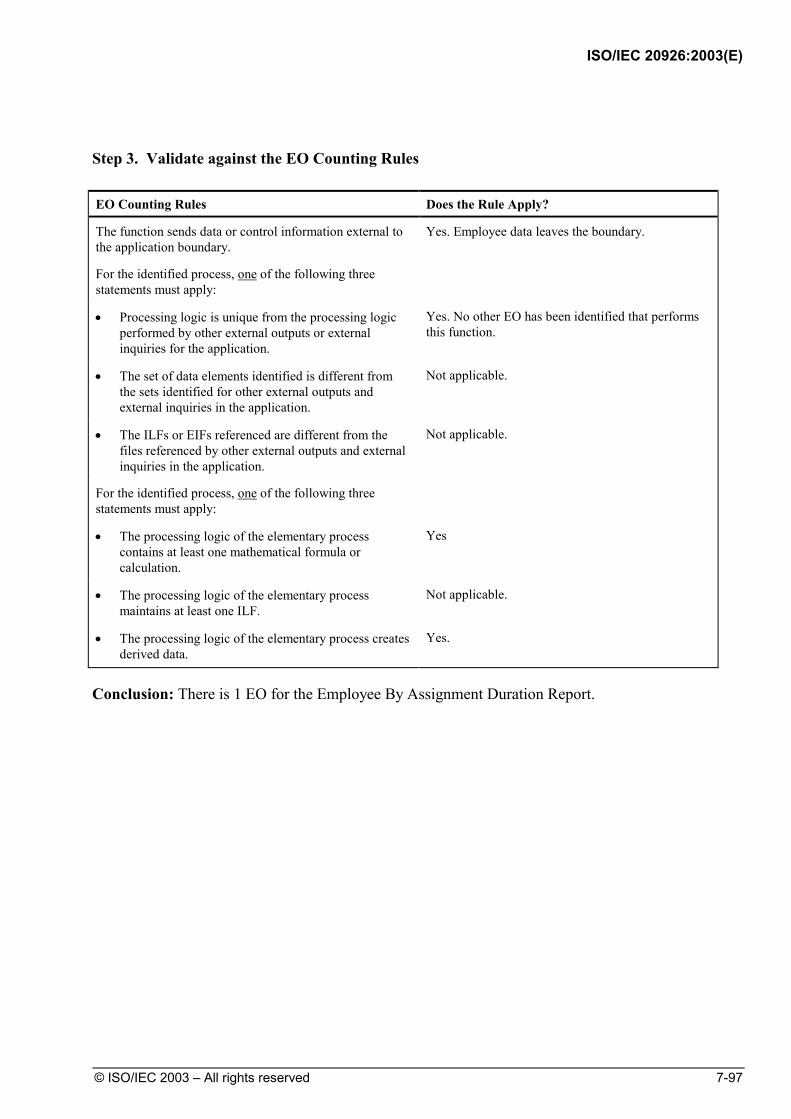
ISO/IEC 20926:2003(E)
© ISO/IEC 2003 – All rights reserved 7-97
Step 3. Validate against the EO Counting Rules EO Counting Rules Does the Rule Apply?
The function sends data or control information external to the application boundary.
Yes. Employee data leaves the boundary.
For the identified process, one of the following three statements must apply:
• Processing logic is unique from the processing logic performed by other external outputs or external inquiries for the application.
Yes. No other EO has been identified that performs this function.
• The set of data elements identified is different from the sets identified for other external outputs and external inquiries in the application.
Not applicable.
• The ILFs or EIFs referenced are different from the files referenced by other external outputs and external inquiries in the application.
Not applicable.
For the identified process, one of the following three statements must apply:
• The processing logic of the elementary process contains at least one mathematical formula or calculation.
Yes
• The processing logic of the elementary process maintains at least one ILF.
Not applicable.
• The processing logic of the elementary process creates derived data.
Yes.
Conclusion: There is 1 EO for the Employee By Assignment Duration Report.
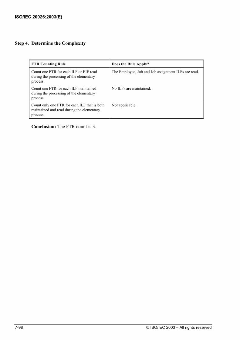
ISO/IEC 20926:2003(E)
7-98 © ISO/IEC 2003 – All rights reserved
Step 4. Determine the Complexity
FTR Counting Rule Does the Rule Apply?
Count one FTR for each ILF or EIF read during the processing of the elementary process.
The Employee, Job and Job assignment ILFs are read.
Count one FTR for each ILF maintained during the processing of the elementary process.
No ILFs are maintained.
Count only one FTR for each ILF that is both maintained and read during the elementary process.
Not applicable.
Conclusion: The FTR count is 3.

ISO/IEC 20926:2003(E)
© ISO/IEC 2003 – All rights reserved 7-99
DET Counting Rules Does the Rule Apply?
Count one DET for each user recognizable, non-repeated field that enters the application boundary and is required to specify when, what and/or how the data is to be retrieved or generated by the elementary process.
Not applicable.
Count one DET for each user recognizable, non-repeated field that exits the boundary.
Totals of employees over 24 mos. and 12 mos., Employee SSN, Employee name, Job number, Job name, and Assignment duration are repeated. Count each only once.
If a DET both enters and exits the boundary, count it only once for the elementary process.
Not applicable.
Count one DET for the capability to send a system response message outside the application boundary to indicate an error occurred during processing, confirm that processing is complete or verify that processing should continue.
Not applicable.
Count one DET for the ability to specify an action to be taken even if there are multiple methods for invoking the same logical process.
Not applicable.
Do not count fields that are retrieved or derived by the system and stored on an ILF during the elementary process if the fields did not cross the application boundary.
Not applicable.
Do not count literals as DETs.
Do not count paging variables or system-generated stamps.
Conclusion: The DET count is 7.
Complexity 3 FTRs and 7 DETs. Complexity is Average
Step 5. Determine the Contribution Contribution is 1 Average Complexity EO 5 FP

ISO/IEC 20926:2003(E)
7-100 © ISO/IEC 2003 – All rights reserved
Example: Transaction Sent to Another Application
User Requirements
When the Human Resources System adds employee dependent data, the user requires that this information is sent to the Benefits application to keep benefits records consistent. This information is sent to Benefits daily.
Construction Requirements
If dependent data is added, that information is formatted properly on the output transaction file.
When implementing a solution, it was decided to include a header and trailer record with the benefits information. These records are used by Benefits to ensure that nothing technically was incorrect when transmitting the file.
Example Record Layout
The following employee dependent record layout contains information about dependent additions and changes.
123456789101234567890123456789012345678901234567890123456789012345678901234567890 0 1 2 3 4 5 6 7 8 1 HFILE NAME DATE 2 DEMP SSN DEP SSN DEPENDENT NAME DEPBDAY 3 TTOTAL REC 4 5 6 7 9 0 1 2 3 4 5 6 7 9 0 1 2 3 4
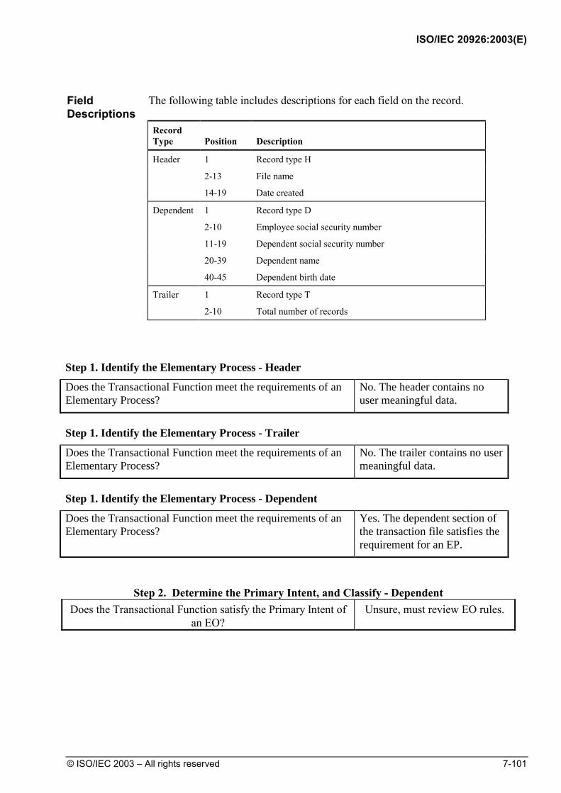
ISO/IEC 20926:2003(E)
© ISO/IEC 2003 – All rights reserved 7-101
Field Descriptions
The following table includes descriptions for each field on the record.
Record Type
Position
Description
Header 1 Record type H
2-13 File name
14-19 Date created
Dependent 1 Record type D
2-10 Employee social security number
11-19 Dependent social security number
20-39 Dependent name
40-45 Dependent birth date
Trailer 1 Record type T
2-10 Total number of records
Step 1. Identify the Elementary Process - Header
Does the Transactional Function meet the requirements of an Elementary Process?
No. The header contains no user meaningful data.
Step 1. Identify the Elementary Process - Trailer
Does the Transactional Function meet the requirements of an Elementary Process?
No. The trailer contains no user meaningful data.
Step 1. Identify the Elementary Process - Dependent
Does the Transactional Function meet the requirements of an Elementary Process?
Yes. The dependent section of the transaction file satisfies the requirement for an EP.
Step 2. Determine the Primary Intent, and Classify - Dependent
Does the Transactional Function satisfy the Primary Intent of an EO?
Unsure, must review EO rules.
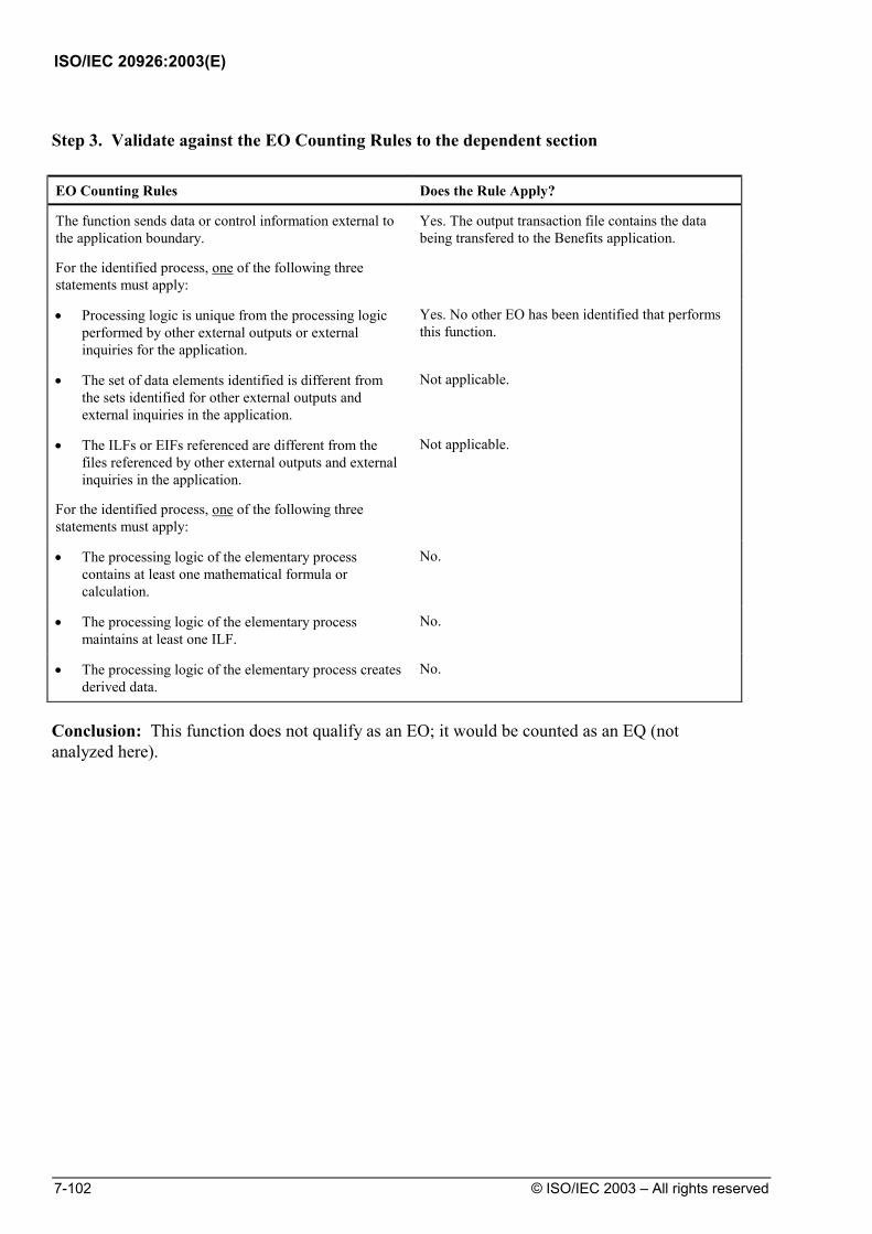
ISO/IEC 20926:2003(E)
7-102 © ISO/IEC 2003 – All rights reserved
Step 3. Validate against the EO Counting Rules to the dependent section EO Counting Rules Does the Rule Apply?
The function sends data or control information external to the application boundary.
Yes. The output transaction file contains the data being transfered to the Benefits application.
For the identified process, one of the following three statements must apply:
• Processing logic is unique from the processing logic performed by other external outputs or external inquiries for the application.
Yes. No other EO has been identified that performs this function.
• The set of data elements identified is different from the sets identified for other external outputs and external inquiries in the application.
Not applicable.
• The ILFs or EIFs referenced are different from the files referenced by other external outputs and external inquiries in the application.
Not applicable.
For the identified process, one of the following three statements must apply:
• The processing logic of the elementary process contains at least one mathematical formula or calculation.
No.
• The processing logic of the elementary process maintains at least one ILF.
No.
• The processing logic of the elementary process creates derived data.
No.
Conclusion: This function does not qualify as an EO; it would be counted as an EQ (not analyzed here).

ISO/IEC 20926:2003(E)
© ISO/IEC 2003 – All rights reserved 7-103
Example: Error/Confirmation Messages
User Requirements
Users require message feedback when job information is maintained. More specifically, users require messages to indicate any edit or validation errors or to indicate that the process completed successfully.
Example Screen
The following Job screen shows a confirmation message (bottom of screen).
Action:_ 7=Prior 8=Following
Job Data Job number: RD15379305 Job name: May Issue - Print Covers Pay grade: JRNY05A Line No Job Description 01 Print Covers 4-Up, Lacquer Finish. ________________________________________________________________ ________________________________________________________________ ________________________________________________________________ ________________________________________________________________ ________________________________________________________________ ________________________________________________________________ ________________________________________________________________ ________________________________________________________________ ________________________________________________________________ F1=Help F7=Scroll up F8=Scroll down F12=Cancel Processing Completed Successfully
Enter: returns to calling screen. F12: returns to calling screen. F1: shows screen or field level help. Action 7: shows prior job data, if present.
F7: scrolls up 10 job description lines. Action 8: shows following job data, if present. F8: scrolls down 10 job description lines.
Step 1. Identify the Elementary Process
Does the Transactional Function meet the requirements of an Elementary Process?
No. The output of an error message is not an EP. It is a DET on the EI.
No further analysis is required.

ISO/IEC 20926:2003(E)
7-104 © ISO/IEC 2003 – All rights reserved
Example: Notification Message
User Requirements
The user requires automatic notification when an employee has completed 12 months in a job assignment. This indicates that a performance review should be completed.
Example Window
The following Performance Review Notification window describes the notification message.
Performance Review Notification
Date: xx/xx/xx Time: hh.mm
Employee: xxx-xx-xxxx x_________________x
Has completed 12 months in assignment:
Job: xxxx x_______________________x
And should be scheduled for a performance review immediately.
Step 1. Identify the Elementary Process
Does the Transactional Function meet the requirements of an Elementary Process?
Yes.
Step 2. Determine the Primary Intent, and Classify
Does the Transactional Function satisfy the Primary Intent of an EO?
Yes. The 12 Month completion date is calculated.

ISO/IEC 20926:2003(E)
© ISO/IEC 2003 – All rights reserved 7-105
Step 3. Validate against the EO Counting Rules EO Counting Rules Does the Rule Apply?
The function sends data or control information external to the application boundary.
Yes. The notification data cross the boundary.
For the identified process, one of the following three statements must apply:
• Processing logic is unique from the processing logic performed by other external outputs or external inquiries for the application.
Yes. No other EO performs this function.
• The set of data elements identified is different from the sets identified for other external outputs and external inquiries in the application.
Not applicable.
• The ILFs or EIFs referenced are different from the files referenced by other external outputs and external inquiries in the application.
Not applicable.
For the identified process, one of the following three statements must apply:
• The processing logic of the elementary process contains at least one mathematical formula or calculation.
12 month completion date is calculated.
• The processing logic of the elementary process maintains at least one ILF.
Not applicable.
• The processing logic of the elementary process creates derived data.
Not applicable.
Conclusion: The notification message is an EO.

ISO/IEC 20926:2003(E)
7-106 © ISO/IEC 2003 – All rights reserved
Step 4. Determine the Complexity
FTR Counting Rule Does the Rule Apply?
Count one FTR for each ILF or EIF read during the processing of the elementary process.
Employee, Job, Job assignment.
Count one FTR for each ILF maintained during the processing of the elementary process.
Not applicable.
Count only one FTR for each ILF that is both maintained and read during the elementary process.
Not applicable.
Conclusion: The FTR count is 3.
DET Counting Rules Does the Rule Apply?
Count one DET for each user recognizable, non-repeated field that enters the application boundary and is required to specify when, what and/or how the data is to be retrieved or generated by the elementary process.
Not applicable.
Count one DET for each user recognizable, non-repeated field that exits the boundary.
Employee social security number, Employee name, Job number, Job name.
If a DET both enters and exits the boundary, count it only once for the elementary process.
Not applicable.
Count one DET for the capability to send a system response message outside the application boundary to indicate an error occurred during processing, confirm that processing is complete or verify that processing should continue.
Not applicable.
Count one DET for the ability to specify an action to be taken even if there are multiple methods for invoking the same logical process.
Not applicable.
Do not count fields that are retrieved or derived by the system and stored on an ILF during the elementary process if the fields did not cross the application boundary.
Do not count literals as DETs.
Do not count paging variables or system-generated stamps.
Conclusion: The DET count is 4.
Complexity 3 FTR and 4 DETs. Complexity is Low

ISO/IEC 20926:2003(E)
© ISO/IEC 2003 – All rights reserved 7-107
Step 5. Determine the Contribution Contribution is 1 Low Complexity EO 4 FP

ISO/IEC 20926:2003(E)
7-108 © ISO/IEC 2003 – All rights reserved
Example: EO Triggered without Data Crossing the Boundary
User Requirement:
Users require that the application print the Weekly Employee Report automatically every Sunday night at 11:00 p.m. The report contains details for each employee plus a total of the employees.
Data Model The following diagram shows the data flow for this example.
Employee ILF SSN Name Location
Print WeeklyEmployee Report
Weekly Employee Report
Name LocationAtlantaMilwaukeeLondonOrange ParkMilfordClarkstonMelbourneAtlantaMontrealMaarssenMaarssen
Benton, A.Bradley, M.Fagg, P.Garmus, D.Glorie, JMarthaler, V.Morris, P.Ragland, R.St-Pierre, D.Timp, A.Van Vliet, E.
Total Employees: 11
Step 1. Identify the Elementary Process
Does the Transactional Function meet the requirements of an Elementary Process?
Yes.
Step 2. Determine the Primary Intent, and Classify
Does the Transactional Function satisfy the Primary Intent of an EO?
Yes. The report contains a calculated field.

ISO/IEC 20926:2003(E)
© ISO/IEC 2003 – All rights reserved 7-109
Step 3. Validate against the EO Counting Rules EO Counting Rules Does the Rule Apply?
The function sends data or control information external to the application boundary.
Yes. The report data crosses the boundary.
For the identified process, one of the following three statements must apply:
• Processing logic is unique from the processing logic performed by other external outputs or external inquiries for the application.
Yes. No other EO performs this function.
• The set of data elements identified is different from the sets identified for other external outputs and external inquiries in the application.
Not applicable.
• The ILFs or EIFs referenced are different from the files referenced by other external outputs and external inquiries in the application.
Not applicable.
For the identified process, one of the following three statements must apply:
• The processing logic of the elementary process contains at least one mathematical formula or calculation.
Yes. Total employees is calculated.
• The processing logic of the elementary process maintains at least one ILF.
Not applicable.
• The processing logic of the elementary process creates derived data.
Not applicable.
Conclusion: The weekly employee report is an EO.

ISO/IEC 20926:2003(E)
7-110 © ISO/IEC 2003 – All rights reserved
Step 4. Determine the Complexity
FTR Counting Rule Does the Rule Apply?
Count one FTR for each ILF or EIF read during the processing of the elementary process.
Employee.
Count one FTR for each ILF maintained during the processing of the elementary process.
No ILF is maintained.
Count only one FTR for each ILF that is both maintained and read during the elementary process.
Not applicable.
Conclusion: The FTR count is 1.
DET Counting Rules Does the Rule Apply?
Count one DET for each user recognizable, non-repeated field that enters the application boundary and is required to specify when, what and/or how the data is to be retrieved or generated by the elementary process.
Not applicable.
Count one DET for each user recognizable, non-repeated field that exits the boundary.
Name, Location,Total Employees.
If a DET both enters and exits the boundary, count it only once for the elementary process.
Not applicable.
Count one DET for the capability to send a system response message outside the application boundary to indicate an error occurred during processing, confirm that processing is complete or verify that processing should continue.
Not applicable.
Count one DET for the ability to specify an action to be taken even if there are multiple methods for invoking the same logical process.
Not applicable.
Do not count fields that are retrieved or derived by the system and stored on an ILF during the elementary process if the fields did not cross the application boundary.
Not applicable.
Do not count literals as DETs.
Do not count paging variables or system-generated stamps.
Conclusion: The DET count is 3.
Complexity 1 FTR and 3 DETs. Complexity is Low
Step 5. Determine the Contribution Contribution is 1 Low Complexity EO 4 FP

ISO/IEC 20926:2003(E)
© ISO/IEC 2003 – All rights reserved 7-111
Example: Primary Function of an EO
User Requirements
Print a check and, as a result, mark the account as paid. All data printed on the check was already stored in the check file.
The following diagram shows the data flow for this example.
Print check
Check ILF Check Number Check Amount Recipient Account Paid Indicator
Step 1. Identify the Elementary Process
Does the Transactional Function meet the requirements of an Elementary Process?
Yes.
Step 2. Determine the Primary Intent, and Classify
Does the Transactional Function satisfy the Primary Intent of an EO?
Yes. The primary intent is to print a check. The maintenance
of the ILF is secondary.

ISO/IEC 20926:2003(E)
7-112 © ISO/IEC 2003 – All rights reserved
Step 3. Validate against the EO Counting Rules EO Counting Rules Does the Rule Apply?
The function sends data or control information external to the application boundary.
Yes. The check information crosses the boundary.
For the identified process, one of the following three statements must apply:
• Processing logic is unique from the processing logic performed by other external outputs or external inquiries for the application.
Yes. No other EO performs this function.
• The set of data elements identified is different from the sets identified for other external outputs and external inquiries in the application.
Not applicable.
• The ILFs or EIFs referenced are different from the files referenced by other external outputs and external inquiries in the application.
Not applicable.
For the identified process, one of the following three statements must apply:
• The processing logic of the elementary process contains at least one mathematical formula or calculation.
Not applicable.
• The processing logic of the elementary process maintains at least one ILF.
Yes. The check ILF is updated.
• The processing logic of the elementary process creates derived data.
Not applicable.
Conclusion: There is 1 EO.

ISO/IEC 20926:2003(E)
© ISO/IEC 2003 – All rights reserved 7-113
Step 4. Determine the Complexity
FTR Counting Rule Does the Rule Apply?
Count one FTR for each ILF or EIF read during the processing of the elementary process.
The check ILF is read.
Count one FTR for each ILF maintained during the processing of the elementary process.
The check file is maintained.
Count only one FTR for each ILF that is both maintained and read during the elementary process.
The check ILF is read and maintained, count only once.
Conclusion: FTR count is 1.

ISO/IEC 20926:2003(E)
7-114 © ISO/IEC 2003 – All rights reserved
DET Counting Rules Does the Rule Apply?
Count one DET for each user recognizable, non-repeated field that enters the application boundary and is required to specify when, what and/or how the data is to be retrieved or generated by the elementary process.
Not applicable.
Count one DET for each user recognizable, non-repeated field that exits the boundary.
Check number, Check amount, Recipient. The Account paid indicator is not counted as it does not cross the boundary. The date is neither stored or printed.
If a DET both enters and exits the boundary, count it only once for the elementary process.
Not applicable.
Count one DET for the capability to send a system response message outside the application boundary to indicate an error occurred during processing, confirm that processing is complete or verify that processing should continue.
Not applicable.
Count one DET for the ability to specify an action to be taken even if there are multiple methods for invoking the same logical process.
Not applicable.
Do not count fields that are retrieved or derived by the system and stored on an ILF during the elementary process if the fields did not cross the application boundary.
Not applicable.
Do not count literals as DETs.
Do not count paging variables or system-generated stamps.
Conclusion: The DET count is 3.
Complexity 1 FTR and 3 DETs. Complexity is Low
Step 5. Determine the Contribution Contribution is 1 Low Complexity EO 4 FP

ISO/IEC 20926:2003(E)
© ISO/IEC 2003 – All rights reserved 7-115
Example: EO Transaction File
User Requirements
At the end of the month, generate a transaction file and send it to Application B. The check numbers and amounts are included on the file with a computed count of the checks processed and the total amount of all of the checks printed for the month.
Data Model The following diagram shows the data flow for this example.
GenerateMonthly CheckFile
Application A
Monthly Check File
Application B
Check numberCheck Amount
No. of Checks PrintedTotal $ for all checks
Check ILF Check Number Check Amount ...
Step 1. Identify the Elementary Process
Does the Transactional Function meet the requirements of an Elementary Process?
Yes.
Step 2. Determine the Primary Intent, and Classify
Does the Transactional Function satisfy the Primary Intent of an EO?
Yes. The primary intent is to generate a transaction file. It
includes calculated fields.

ISO/IEC 20926:2003(E)
7-116 © ISO/IEC 2003 – All rights reserved
Step 3. Validate against the EO Counting Rules EO Counting Rules Does the Rule Apply?
The function sends data or control information external to the application boundary.
Yes. Transaction data exits the application.
For the identified process, one of the following three statements must apply:
• Processing logic is unique from the processing logic performed by other external outputs or external inquiries for the application.
Yes. No other EO performs this function.
• The set of data elements identified is different from the sets identified for other external outputs and external inquiries in the application.
Not applicable.
• The ILFs or EIFs referenced are different from the files referenced by other external outputs and external inquiries in the application.
Not applicable.
For the identified process, one of the following three statements must apply:
• The processing logic of the elementary process contains at least one mathematical formula or calculation.
Yes. The number of checks and the total value are calculated.
• The processing logic of the elementary process maintains at least one ILF.
Not applicable.
• The processing logic of the elementary process creates derived data.
Not applicable.
Conclusion: There is 1 EO.

ISO/IEC 20926:2003(E)
© ISO/IEC 2003 – All rights reserved 7-117
Step 4. Determine the Complexity
FTR Counting Rule Does the Rule Apply?
Count one FTR for each ILF or EIF read during the processing of the elementary process.
The Check ILF is read.
Count one FTR for each ILF maintained during the processing of the elementary process.
Not applicable.
Count only one FTR for each ILF that is both maintained and read during the elementary process.
Not applicable.
Conclusion: The FTR count is 1.
DET Counting Rules Does the Rule Apply?
Count one DET for each user recognizable, non-repeated field that enters the application boundary and is required to specify when, what and/or how the data is to be retrieved or generated by the elementary process.
Not applicable.
Count one DET for each user recognizable, non-repeated field that exits the boundary.
Check number, Amount, No. of checks printed, Total $ for all checks.
If a DET both enters and exits the boundary, count it only once for the elementary process.
Not applicable.
Count one DET for the capability to send a system response message outside the application boundary to indicate an error occurred during processing, confirm that processing is complete or verify that processing should continue.
Not applicable.
Count one DET for the ability to specify an action to be taken even if there are multiple methods for invoking the same logical process.
Not applicable.
Do not count fields that are retrieved or derived by the system and stored on an ILF during the elementary process if the fields did not cross the application boundary.
Do not count literals as DETs.
Do not count paging variables or system-generated stamps.
Conclusion: The DET count is 4.
Complexity 1 FTR and 4 DETs. Complexity is Low
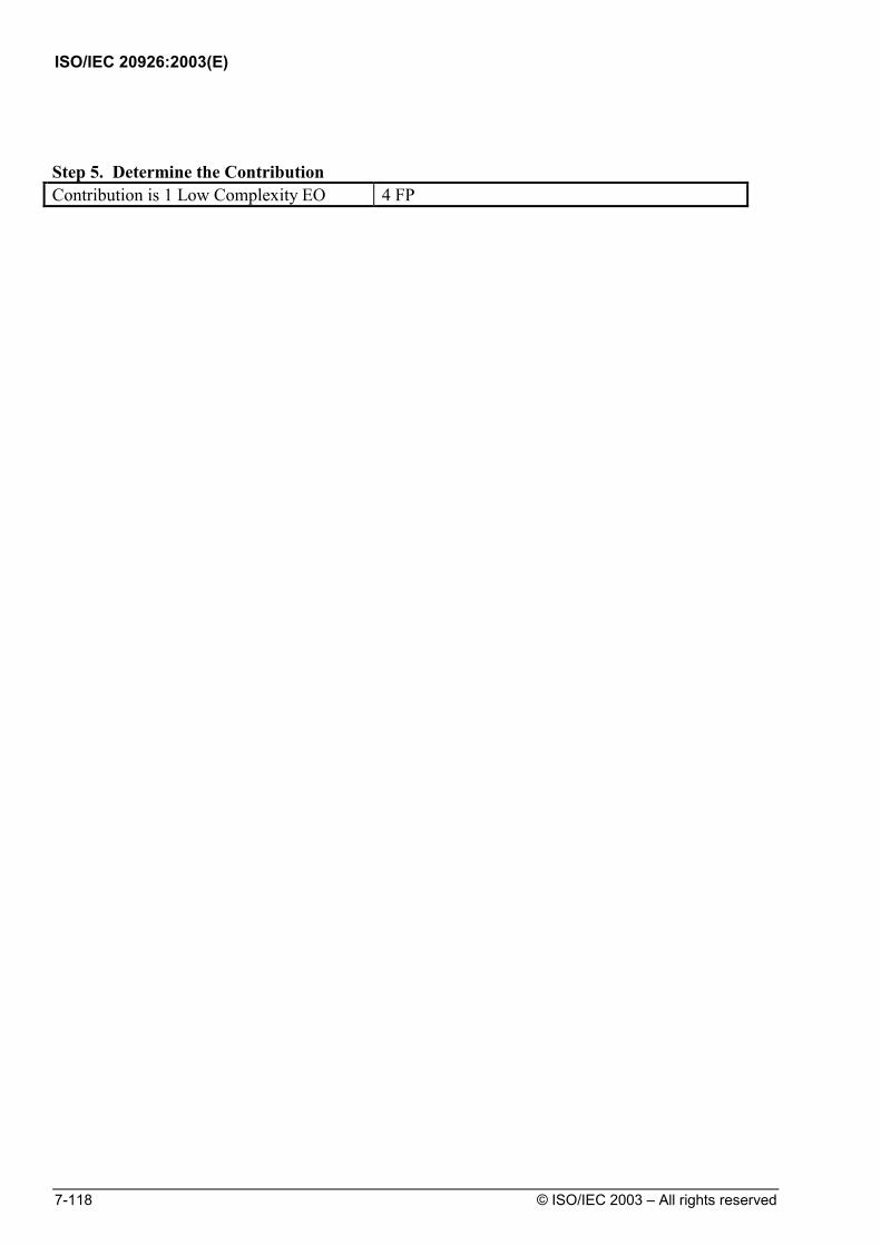
ISO/IEC 20926:2003(E)
7-118 © ISO/IEC 2003 – All rights reserved
Step 5. Determine the Contribution Contribution is 1 Low Complexity EO 4 FP

ISO/IEC 20926:2003(E)
© ISO/IEC 2003 – All rights reserved 7-119
Summary of EOs, FTRs and DETs Counted
This section gives a summary of the EOs, FTRs, and DETs counted before
calculating the complexity and contribution to the unadjusted function point count.
Summary of EOs Counted
The following table shows the EOs counted for the HR application. It also lists the data that was not counted.
EOs Counted Not Counted Jobs with Employees Report New dependent transactions to benefits
Employees by Assignment Duration Report error/confirmation messages
Performance Review Notification Weekly Employee Report Printed Check Check Transaction File

ISO/IEC 20926:2003(E)
7-120 © ISO/IEC 2003 – All rights reserved
Summary FTR/DET Count
The FTR and DET counts are recorded in the following table.
External Output FTRs DETs Jobs with Employees Report 4 5 Employees by Assignment Duration Report 3 7 Performance Review Notification 3 4 Weekly Employee Report 1 3 Printed Check 1 3 Check Transaction File 1 4
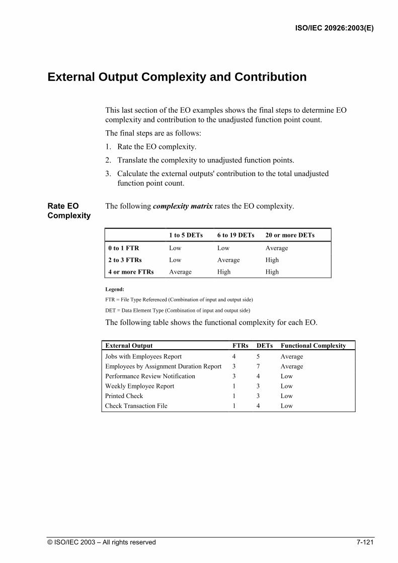
ISO/IEC 20926:2003(E)
© ISO/IEC 2003 – All rights reserved 7-121
External Output Complexity and Contribution
This last section of the EO examples shows the final steps to determine EO
complexity and contribution to the unadjusted function point count.
The final steps are as follows:
1. Rate the EO complexity.
2. Translate the complexity to unadjusted function points.
3. Calculate the external outputs' contribution to the total unadjusted function point count.
Rate EO Complexity
The following complexity matrix rates the EO complexity.
1 to 5 DETs 6 to 19 DETs 20 or more DETs
0 to 1 FTR Low Low Average
2 to 3 FTRs Low Average High
4 or more FTRs Average High High
Legend:
FTR = File Type Referenced (Combination of input and output side)
DET = Data Element Type (Combination of input and output side)
The following table shows the functional complexity for each EO.
External Output FTRs DETs Functional Complexity Jobs with Employees Report 4 5 Average Employees by Assignment Duration Report 3 7 Average Performance Review Notification 3 4 Low Weekly Employee Report 1 3 Low Printed Check 1 3 Low Check Transaction File 1 4 Low
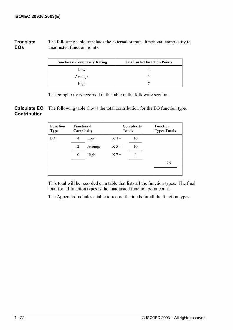
ISO/IEC 20926:2003(E)
7-122 © ISO/IEC 2003 – All rights reserved
Translate EOs
The following table translates the external outputs' functional complexity to unadjusted function points.
Functional Complexity Rating Unadjusted Function Points
Low 4
Average 5
High 7
The complexity is recorded in the table in the following section.
Calculate EO Contribution
The following table shows the total contribution for the EO function type.
Function Type
Functional Complexity
Complexity Totals
Function Types Totals
EO 4 Low X 4 = 16
2 Average X 5 = 10
0 High X 7 = 0
26
This total will be recorded on a table that lists all the function types. The final total for all function types is the unadjusted function point count.
The Appendix includes a table to record the totals for all the function types.
ISO/IEC 20926:2003(E)
© ISO/IEC 2003 – All rights reserved 7-123
EQ Counting Examples Introduction This section uses a Human Resources (HR) application to illustrate
procedures to count external inquiries. In addition to this section, examples are in the Case Studies included in the complementary IFPUG documentation.
Contents This section includes the following examples:
Topic See Page
Shared Rules for All Transactional Function Types 7-124
Summary Descriptions of EQ Counting Examples 7-125
Example: Application Menus 7-126
Example: List of Retrieved Data 7-128
Example: Drop-Down List Box 7-133
Example: Field Level Help–First Occurrence 7-137
Example: Field Level Help–Second Occurrence 7-141
Example: Implied Inquiry 7-144
Example: EQ Triggered without Data Crossing the Boundary 7-147
Example: Data Sent to Another Application 7-150
Summary of EQs, FTRs and DETs Counted 7-153
External Inquiries Complexity and Contribution 7-154

ISO/IEC 20926:2003(E)
7-124 © ISO/IEC 2003 – All rights reserved
Shared Rules for All Transactional Function Types
The process to analyze all the examples follows the process described earlier in this chapter. Steps of the process are concerned with applying the rules for identifying Elementary Processes, the Primary Intent and the classification of the Transactional Function type into EI, EO, or EQ. The following tables list the rules that must be applied: Elementary Process Counting Rules Does the Rule Apply?
The process is the smallest unit of activity that is meaningful to the user.
The process is self-contained and leaves the business of the application in a consistent state.
The answer to both questions must be ‘YES’ for the Transactional Function to be an Elementary Process. Primary Intent
EI To maintain an ILF or alter the behavior of the system.
EO To present information to a user.
It presents data that is calculated or derived, it updates 1 or more ILFs, or it alters the behavior of the system.
EQ To present information to a user.
It presents only data that is retrieved from 1 or more ILFs or EIFs.
Use the description that best matches the primary intent of the Transactional Function type to determine whether it is an EI, EO or EQ. This can be determined by careful and accurate interpretation of the user requirements for the function.

ISO/IEC 20926:2003(E)
© ISO/IEC 2003 – All rights reserved 7-125
Summary Descriptions of EQ Counting Examples
The examples for EQs are listed and described in the following table.
Example Summary Description Page
Application Menus This example shows why navigational menus or other navigational aids are not counted as EQs.
7-126
List of Retrieved Data This example illustrates the count for a list. 7-128
Drop-Down List Box This example shows how a drop-down list box is counted.
7-133
Field Level Help–First Occurrence
This example illustrates how field level help is counted for the first occurrence.
7-137
Field Level Help–Second Occurrence
Counting a second instance of field level help is shown in this example.
7-141
Implied Inquiry This example shows the function point count when data retrieval is not explicitly stated but it is implied.
7-144
EQ Triggered without Data Crossing the Boundary
This example illustrates the count for data retrieval and display triggered internally by time.
7-147
Transaction Sent to Another Application
This example illustrates the count of data sent to another application via a file.
7-150

ISO/IEC 20926:2003(E)
7-126 © ISO/IEC 2003 – All rights reserved
Example: Application Menus
User Requirements
The Human Resources application requires navigation menus and aids.
Counting Process
The following diagram shows the Employee drop-down menu on the Human Resources System main menu. This is the input request.
Human Resources System
NewReviewEditReport
Jobs Assignments Locations HelpEmployee Rpt Man Security

ISO/IEC 20926:2003(E)
© ISO/IEC 2003 – All rights reserved 7-127
When the user selects New on the Employee drop-down menu, the following
empty Employee Setup window is displayed.
Last Name
First Name
Middle Initial
Social Security Number
Number of Dependents
Location Main Office
Currency Location
Salary Type ( ) Hourly ( ) Salaried
Human Resources System
Employee Setup
OK
Cancel
OK
Cancel Goes back to pull down menu
Navigates to next screen:• EN-2H, if hourly salary type is selected• EN-2S, if salaried salary type is selected
EN-1
Jobs Assignments Locations HelpEmployee Rpt Man Security
Step 1. Identify the Elementary Process
Does the Transactional Function meet the requirements of an Elementary Process?
No. Selection from a menu of options does not include any data meaningful to the user.
Conclusion: There is no elementary process.

ISO/IEC 20926:2003(E)
7-128 © ISO/IEC 2003 – All rights reserved
Example: List of Retrieved Data
User Requirements
The user has the following requirements:
• View a list of employees.
This example focuses on viewing a list of employees in the Human Resources application.
The following diagram shows the data flow for this example.
EMPL/DEP
User
1.4
Inquire Employee
1.5
ssn
emplinfo
ssn, name, type, supv_cd, hr_rate,bu_#, dep_ssn, dep_name, dep_birth,loc_name
Employee Listssn, name, type,sal_type,empl info Inquire List
of Employees
EmployeeSecurity
Review Request
access allowed
access allowed

ISO/IEC 20926:2003(E)
© ISO/IEC 2003 – All rights reserved 7-129
Counting Process
The following diagram shows the drop-down menu for employee. The Review field and the enter key make up the input side of this example.
Human Resources System
NewReviewEditReport
Jobs Assignments Locations HelpEmployee Rpt Man Security
When the user selects Review on the Employee drop-down menu, the
following window displays with a list of employees.
Human Resources System
Employee List
Cancel
EI-1
Last Name First Name MI Social Security Salary Type
Keller
Latta
Manship
Schmidt-Taylor
Smith
Smith
Caroline
Nicky
Mark
Kathleen
David
Loretta
A
J
E
M
123-45-6789
234-56-7890
345-67-8901
456-78-9012
567-89-0123
678-90-1234
Salaried
Hourly
Hourly
Salaried
Hourly
Salaried
DependentsView
View Initiates display of data on EI-2
Initiates list displayed on EI-4
Returns to pull down menu
Dependents
Cancel
Jobs Assignments Locations HelpEmployee Rpt Man Security

ISO/IEC 20926:2003(E)
7-130 © ISO/IEC 2003 – All rights reserved
Step 1. Identify the Elementary Process
Does the Transactional Function meet the requirements of an Elementary Process?
Yes.
Step 2. Determine the Primary Intent, and Classify
Does the Transactional Function satisfy the Primary Intent of an EQ?
Yes. The primary intent is to present data. Only retrieved data
is involved. Step 3. Validate against the EQ Counting Rules
EQ Counting Rules Does the Rule Apply?
The function sends data or control information external to the application boundary.
Yes. The employee data crosses the boundary.
For the identified process, one of the following three statements must apply:
• Processing logic is unique from the processing logic performed by other external outputs or external inquiries for the application.
Yes. No other EQ performs this function.
• The set of data elements identified is different from the sets identified for other external outputs and external inquiries in the application.
Not applicable.
• The ILFs or EIFs referenced are different from the files referenced by other external outputs and external inquiries in the application.
Not applicable.
The processing logic of the elementary process retrieves data or control information from an ILF or EIF.
Yes. Employee data is retrieved.
The processing logic of the elementary process does not maintain an ILF.
Yes.
The processing logic of the elementary process does not contain a mathematical formula or calculation.
Yes.
The processing logic of the elementary process does not create derived data.
Yes.
Conclusion: 1 EQ is counted.

ISO/IEC 20926:2003(E)
© ISO/IEC 2003 – All rights reserved 7-131
Step 4. Determine the Complexity
FTR Counting Rule Does the Rule Apply?
Count one FTR for each ILF or EIF read during the processing of the elementary process.
Yes. Employee.
Conclusion: The FTR count is 1.
DET Counting Rules Does the Rule Apply?
Count one DET for each user recognizable, non-repeated field that enters the application boundary and is required to specify when, what and/or how the data is to be retrieved or generated by the elementary process.
Not applicable.
Count one DET for each user recognizable, non-repeated field that exits the boundary.
The following are repeated, they are counted only once. (Last Name + First Name + MI), SSN, Salary type.
If a DET both enters and exits the boundary, count it only once for the elementary process.
Not applicable.
Count one DET for the capability to send a system response message outside the application boundary to indicate an error occurred during processing, confirm that processing is complete or verify that processing should continue.
Not applicable.
Count one DET for the ability to specify an action to be taken even if there are multiple methods for invoking the same logical process.
Yes, the review field/enter key.
Do not count fields that are retrieved or derived by the system and stored on an ILF during the elementary process if the fields did not cross the application boundary.
Not applicable.
Do not count literals as DETs.
Do not count paging variables or system-generated stamps.
Conclusion: The DET count is 4. The name is considered together as one DET.

ISO/IEC 20926:2003(E)
7-132 © ISO/IEC 2003 – All rights reserved
Complexity 1 FTR and 4 DETs. Complexity is Low
Step 5. Determine the Contribution Contribution is 1 Low Complexity EQ 3 FP

ISO/IEC 20926:2003(E)
© ISO/IEC 2003 – All rights reserved 7-133
Example: Drop-Down List Box
User Requirements
The user requires the ability to view a list of bargaining units added to the Human Resources System by a user.
Counting Process
The following diagram shows the Hourly Employee Data window with the Bargaining Unit field.
Employee List
Human Resources System
EI-3HPresents list on EI-4Dependents
Employee Data
Mark Manship
345-67-8901
Hourly Employee Data
Hourly Rate
Bargaining Unit Dependents
J
Jobs Assignments Locations HelpEmployee Rpt Man Security

ISO/IEC 20926:2003(E)
7-134 © ISO/IEC 2003 – All rights reserved
When the user selects the arrow, the following drop-down list box appears.
Employee List
Human Resources System
EI-3HPresents list on EI-4Dependents
Employee Data
Mark Manship
345-67-8901
Hourly Employee Data
Hourly Rate
Bargaining Unit Dependents
J
Jobs Assignments Locations HelpEmployee Rpt Man Security
UPFCAL841CPLG
Step 1. Identify the Elementary Process
Does the Transactional Function meet the requirements of an Elementary Process?
Yes.
Step 2. Determine the Primary Intent, and Classify
Does the Transactional Function satisfy the Primary Intent of an EQ?
Yes. The primary intent is to is to present information. Only
retrieved data is involved.
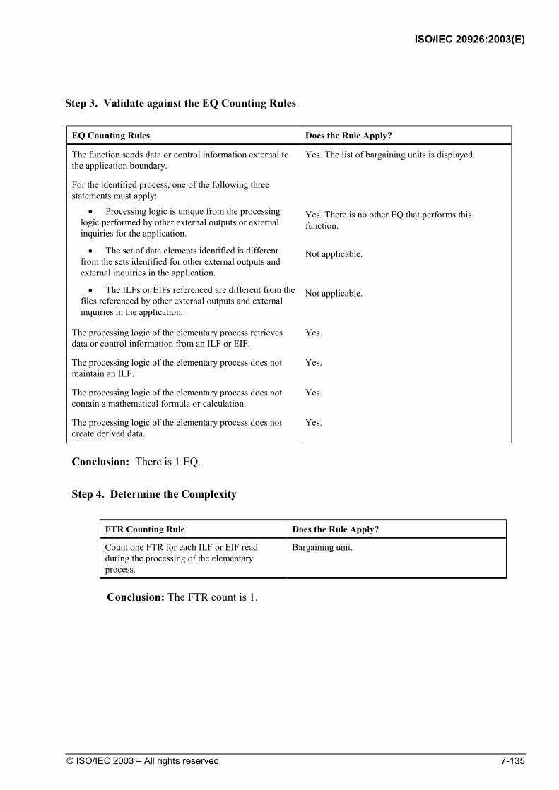
ISO/IEC 20926:2003(E)
© ISO/IEC 2003 – All rights reserved 7-135
Step 3. Validate against the EQ Counting Rules
EQ Counting Rules Does the Rule Apply?
The function sends data or control information external to the application boundary.
Yes. The list of bargaining units is displayed.
For the identified process, one of the following three statements must apply:
• Processing logic is unique from the processing logic performed by other external outputs or external inquiries for the application.
Yes. There is no other EQ that performs this function.
• The set of data elements identified is different from the sets identified for other external outputs and external inquiries in the application.
Not applicable.
• The ILFs or EIFs referenced are different from the files referenced by other external outputs and external inquiries in the application.
Not applicable.
The processing logic of the elementary process retrieves data or control information from an ILF or EIF.
Yes.
The processing logic of the elementary process does not maintain an ILF.
Yes.
The processing logic of the elementary process does not contain a mathematical formula or calculation.
Yes.
The processing logic of the elementary process does not create derived data.
Yes.
Conclusion: There is 1 EQ.
Step 4. Determine the Complexity
FTR Counting Rule Does the Rule Apply?
Count one FTR for each ILF or EIF read during the processing of the elementary process.
Bargaining unit.
Conclusion: The FTR count is 1.
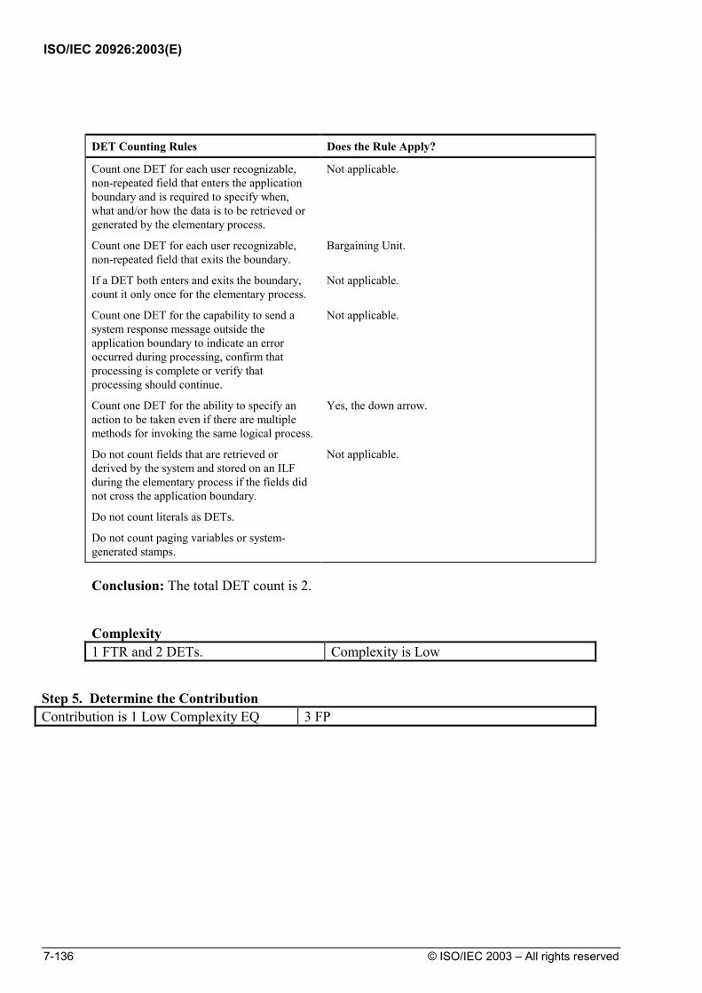
ISO/IEC 20926:2003(E)
7-136 © ISO/IEC 2003 – All rights reserved
DET Counting Rules Does the Rule Apply?
Count one DET for each user recognizable, non-repeated field that enters the application boundary and is required to specify when, what and/or how the data is to be retrieved or generated by the elementary process.
Not applicable.
Count one DET for each user recognizable, non-repeated field that exits the boundary.
Bargaining Unit.
If a DET both enters and exits the boundary, count it only once for the elementary process.
Not applicable.
Count one DET for the capability to send a system response message outside the application boundary to indicate an error occurred during processing, confirm that processing is complete or verify that processing should continue.
Not applicable.
Count one DET for the ability to specify an action to be taken even if there are multiple methods for invoking the same logical process.
Yes, the down arrow.
Do not count fields that are retrieved or derived by the system and stored on an ILF during the elementary process if the fields did not cross the application boundary.
Not applicable.
Do not count literals as DETs.
Do not count paging variables or system-generated stamps.
Conclusion: The total DET count is 2.
Complexity 1 FTR and 2 DETs. Complexity is Low
Step 5. Determine the Contribution Contribution is 1 Low Complexity EQ 3 FP

ISO/IEC 20926:2003(E)
© ISO/IEC 2003 – All rights reserved 7-137
Example: Field Level Help–First Occurrence
User Requirements
During construction of the Human Resources System, a requirement for online field level help was added. The help facility is provided by a separate application. The Help application provides help to the Human Resources, Currency, Fixed Assets, and Benefits applications.
Counting Process
The following diagram shows the Employee Data window.
Employee List
Human Resources System
EI-3HPresents list on EI-4Dependents
Employee Data
Mark Manship
345-67-8901
Hourly Employee Data
Hourly Rate
Bargaining Unit Dependents
J
Jobs Assignments Locations HelpEmployee Rpt Man Security

ISO/IEC 20926:2003(E)
7-138 © ISO/IEC 2003 – All rights reserved
When the user presses F1 while the cursor is on the hourly rate field, a box
displays the help text as shown in the following diagram.
Human Resources System
EI-3HPresents list on EI-4Dependents
Hourly Rate
Bargaining Unit Dependents
Jobs Assignments Locations HelpEmployee Rpt Man Security
Hourly Rate
The amount an employee is paid for each hour of
This information must be provided for each hourly employee.
Valid Values: Any hourly amount is acceptable.Default Values: This field does not have default values.
work completed.
Step 1. Identify the Elementary Process
Does the Transactional Function meet the requirements of an Elementary Process?
Yes.
Step 2. Determine the Primary Intent, and Classify
Does the Transactional Function satisfy the Primary Intent of an EQ?
Yes. The primary intent is to present information. Only retrieved data is involved.

ISO/IEC 20926:2003(E)
© ISO/IEC 2003 – All rights reserved 7-139
Step 3. Validate against the EQ Counting Rules
EQ Counting Rules Does the Rule Apply?
The function sends data or control information external to the application boundary.
Yes. Help information crosses the boundary.
For the identified process, one of the following three statements must apply:
• Processing logic is unique from the processing logic performed by other external outputs or external inquiries for the application.
Yes. No other EQ performs this function.
• The set of data elements identified is different from the sets identified for other external outputs and external inquiries in the application.
Not applicable.
• The ILFs or EIFs referenced are different from the files referenced by other external outputs and external inquiries in the application.
Not applicable.
The processing logic of the elementary process retrieves data or control information from an ILF or EIF.
Yes.
The processing logic of the elementary process does not maintain an ILF.
Yes.
The processing logic of the elementary process does not contain a mathematical formula or calculation.
Yes.
The processing logic of the elementary process does not create derived data.
Yes.
Conclusion: This is 1 EQ.
Step 4. Determine the Complexity
FTR Counting Rule Does the Rule Apply?
Count one FTR for each ILF or EIF read during the processing of the elementary process.
Help.
Conclusion: The FTR count is 1.

ISO/IEC 20926:2003(E)
7-140 © ISO/IEC 2003 – All rights reserved
DET Counting Rules Does the Rule Apply?
Count one DET for each user recognizable, non-repeated field that enters the application boundary and is required to specify when, what and/or how the data is to be retrieved or generated by the elementary process.
Window ID, Field ID.
Count one DET for each user recognizable, non-repeated field that exits the boundary.
Help message, Default value, Valid values.
If a DET both enters and exits the boundary, count it only once for the elementary process.
Not applicable.
Count one DET for the capability to send a system response message outside the application boundary to indicate an error occurred during processing, confirm that processing is complete or verify that processing should continue.
Not applicable.
Count one DET for the ability to specify an action to be taken even if there are multiple methods for invoking the same logical process.
Yes. The F1 key.
Do not count fields that are retrieved or derived by the system and stored on an ILF during the elementary process if the fields did not cross the application boundary.
Not applicable.
Do not count literals as DETs.
Do not count paging variables or system-generated stamps.
Conclusion: The DET count is 6.
Complexity 1 FTR and 6 DETs. Complexity is Low
Step 5. Determine the Contribution Contribution is 1 Low Complexity EQ 3 FP
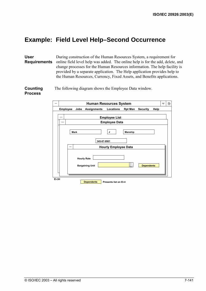
ISO/IEC 20926:2003(E)
© ISO/IEC 2003 – All rights reserved 7-141
Example: Field Level Help–Second Occurrence
User Requirements
During construction of the Human Resources System, a requirement for online field level help was added. The online help is for the add, delete, and change processes for the Human Resources information. The help facility is provided by a separate application. The Help application provides help to the Human Resources, Currency, Fixed Assets, and Benefits applications.
Counting Process
The following diagram shows the Employee Data window.
Employee List
Human Resources System
EI-3HPresents list on EI-4Dependents
Employee Data
Mark Manship
345-67-8901
Hourly Employee Data
Hourly Rate
Bargaining Unit Dependents
J
Jobs Assignments Locations HelpEmployee Rpt Man Security
ISO/IEC 20926:2003(E)
7-142 © ISO/IEC 2003 – All rights reserved
The user places the cursor on the field for which help is desired, and presses
F1 to view help about that field.
Step 1. Identify the Elementary Process
Does the Transactional Function meet the requirements of an Elementary Process?
Yes.
Step 2. Determine the Primary Intent, and Classify
Does the Transactional Function satisfy the Primary Intent of an EQ?
Yes. The primary intent is to present information. Only retrieved data is involved.
ISO/IEC 20926:2003(E)
© ISO/IEC 2003 – All rights reserved 7-143
Step 3. Validate against the EQ Counting Rules
EQ Counting Rules Does the Rule Apply?
The function sends data or control information external to the application boundary.
Yes. Help information crosses the boundary.
For the identified process, one of the following three statements must apply:
• Processing logic is unique from the processing logic performed by other external outputs or external inquiries for the application.
No. The processing logic to present field level help for this field has been identified previously.
• The set of data elements identified is different from the sets identified for other external outputs and external inquiries in the application.
Not applicable.
• The ILFs or EIFs referenced are different from the files referenced by other external outputs and external inquiries in the application.
Not applicable.
The processing logic of the elementary process retrieves data or control information from an ILF or EIF.
Not applicable.
The processing logic of the elementary process does not maintain an ILF.
Not applicable.
The processing logic of the elementary process does not contain a mathematical formula or calculation.
Not applicable.
The processing logic of the elementary process does not create derived data.
Not applicable.
Conclusion: Although this is an Elementary Process, it is not counted because it is not a unique function in this application. Field level help has already been counted.

ISO/IEC 20926:2003(E)
7-144 © ISO/IEC 2003 – All rights reserved
Example: Implied Inquiry
User Requirements
The user requires the ability to view assignment information. Although it is not explicitly stated, it is implied that job information must be retrieved before it can be changed. It is not efficient for the user to enter changes to the job assignment information without first viewing the existing information. This is the implied inquiry.
Counting Process
The following diagram shows the Job Assignment Edit window with only the employee name and job number.
Human Resources System
Employee Assignments
AE-5
Job Assignment Edit
Mark J Manship
Job Number
Date
Salary
Performance Rating
RD15379305 May Issue - Print Covers
OK
Cancel
Restore
Delete
OK
Cancel
Restore
Delete
Commits changes, returns to AE-1
Ignores changes, returns to AE-1
Restores prior values
Asks for confirmation, then deletes job assignment
Assignments Locations HelpEmployee Rpt Man SecurityJobs

ISO/IEC 20926:2003(E)
© ISO/IEC 2003 – All rights reserved 7-145
When the user enters employee name and job number, the job information
appears as shown in the following diagram.
Human Resources System
Employee Assignments
AE-5
Job Assignment Edit
Mark J Manship
345-67-8901
Main Plant UFPCA
Job Number
Date
Salary
Performance Rating
03/27/93
17.28
Satisfactory
RD15379305 May Issue - Print Covers
OK
Cancel
Restore
Delete
OK
Cancel
Restore
Delete
Commits changes, returns to AE-1
Ignores changes, returns to AE-1
Restores prior values
Asks for confirmation, then deletes job assignment
Assignments Locations HelpEmployee Rpt Man SecurityJobs
Step 1. Identify the Elementary Process
Does the Transactional Function meet the requirements of an Elementary Process?
Yes.
Step 2. Determine the Primary Intent, and Classify
Does the Transactional Function satisfy the Primary Intent of an EQ?
Yes. The primary intent is to present information. Only retrieved data is involved.

ISO/IEC 20926:2003(E)
7-146 © ISO/IEC 2003 – All rights reserved
Step 3. Validate against the EQ Counting Rules
EQ Counting Rules Does the Rule Apply?
The function sends data or control information external to the application boundary.
Yes. Job information is displayed.
For the identified process, one of the following three statements must apply:
• Processing logic is unique from the processing logic performed by other external outputs or external inquiries for the application.
No. There is an existing EQ, which provides a view of the same information.
• The set of data elements identified is different from the sets identified for other external outputs and external inquiries in the application.
Not applicable.
• The ILFs or EIFs referenced are different from the files referenced by other external outputs and external inquiries in the application.
Not applicable.
The processing logic of the elementary process retrieves data or control information from an ILF or EIF.
Not applicable.
The processing logic of the elementary process does not maintain an ILF.
Not applicable.
The processing logic of the elementary process does not contain a mathematical formula or calculation.
Not applicable.
The processing logic of the elementary process does not create derived data.
Not applicable.
Conclusion: Although the function is an elementary process, it is not counted because it is not unique within this application. An identical display has previously been counted.

ISO/IEC 20926:2003(E)
© ISO/IEC 2003 – All rights reserved 7-147
Example: EQ Triggered without Data Crossing the Boundary
User Requirements
The user requires that the application print the Monthly Membership Report automatically every month.
The following diagram shows the data flow for this example.
Print MonthlyMembership Report
Monthly Membership Report
Name City
Angel, A.Boxer, B.Smith, S.Temple, S.Wayne, J.
MilwaukeeChicagoLondonDetroitAtlanta
Membership ILF Member ID Name City
Country
USAUSAUKUSAUSA
Country
Step 1. Identify the Elementary Process
Does the Transactional Function meet the requirements of an Elementary Process?
Yes.
Step 2. Determine the Primary Intent, and Classify
Does the Transactional Function satisfy the Primary Intent of an EQ?
Yes. The primary intent is to present information. Only retrieved data is involved.
Step 3. Validate against the EQ Counting Rules
ISO/IEC 20926:2003(E)
7-148 © ISO/IEC 2003 – All rights reserved
EQ Counting Rules Does the Rule Apply?
The function sends data or control information external to the application boundary.
Yes. The monthly membership data crosses the boundary.
For the identified process, one of the following three statements must apply:
• Processing logic is unique from the processing logic performed by other external outputs or external inquiries for the application.
Yes. No other EQ performs this function.
• The set of data elements identified is different from the sets identified for other external outputs and external inquiries in the application.
Not applicable.
• The ILFs or EIFs referenced are different from the files referenced by other external outputs and external inquiries in the application.
Not applicable.
The processing logic of the elementary process retrieves data or control information from an ILF or EIF.
Yes.
The processing logic of the elementary process does not maintain an ILF.
Yes.
The processing logic of the elementary process does not contain a mathematical formula or calculation.
Yes.
The processing logic of the elementary process does not create derived data.
Yes.
Conclusion: There is 1 EQ. Note, an EQ can be triggered without data crossing the boundary. In this example, the transaction is triggered by a time event within the application boundary.
Step 4. Determine the Complexity
FTR Counting Rule Does the Rule Apply?
Count one FTR for each ILF or EIF read during the processing of the elementary process.
Membership.
Conclusion: The total FTR count is 1.

ISO/IEC 20926:2003(E)
© ISO/IEC 2003 – All rights reserved 7-149
For DETs, look at each field on the window and determine which DET counting rules apply.
DET Counting Rules Does the Rule Apply?
Count one DET for each user recognizable, non-repeated field that enters the application boundary and is required to specify when, what and/or how the data is to be retrieved or generated by the elementary process.
Not applicable.
Count one DET for each user recognizable, non-repeated field that exits the boundary.
Name, city, country.
If a DET both enters and exits the boundary, count it only once for the elementary process.
Not applicable.
Count one DET for the capability to send a system response message outside the application boundary to indicate an error occurred during processing, confirm that processing is complete or verify that processing should continue.
Not applicable.
Count one DET for the ability to specify an action to be taken even if there are multiple methods for invoking the same logical process.
Not applicable.
Do not count fields that are retrieved or derived by the system and stored on an ILF during the elementary process if the fields did not cross the application boundary.
Not applicable.
Do not count literals as DETs.
Do not count paging variables or system-generated stamps.
Conclusion: The DET count is 3.
Complexity 1 FTR and 3 DETs. Complexity is Low
Step 5. Determine the Contribution Contribution is 1 Low Complexity EQ 3 FP
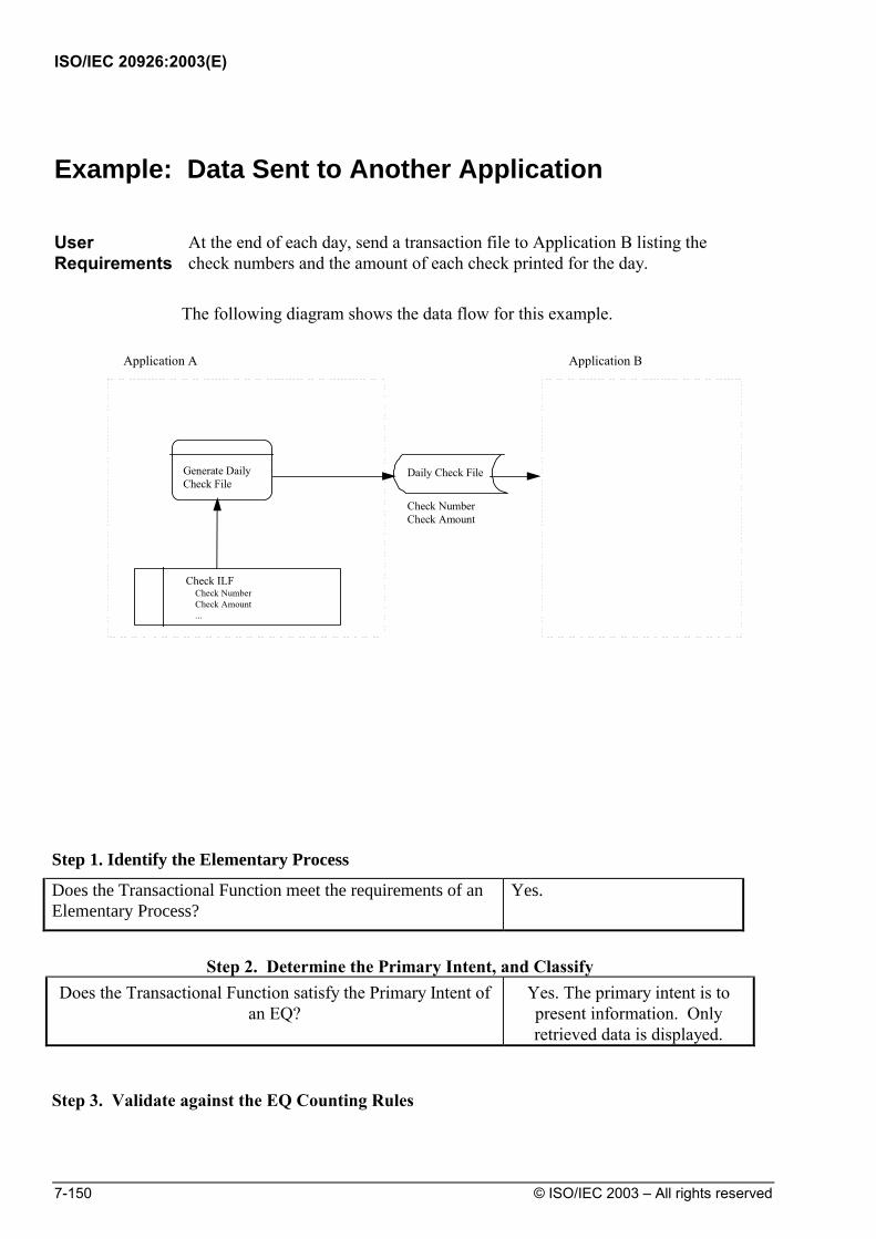
ISO/IEC 20926:2003(E)
7-150 © ISO/IEC 2003 – All rights reserved
Example: Data Sent to Another Application
User Requirements
At the end of each day, send a transaction file to Application B listing the check numbers and the amount of each check printed for the day.
The following diagram shows the data flow for this example.
Check ILF Check Number Check Amount ...
Generate DailyCheck File
Application A
Daily Check File
Application B
Check NumberCheck Amount
Step 1. Identify the Elementary Process
Does the Transactional Function meet the requirements of an Elementary Process?
Yes.
Step 2. Determine the Primary Intent, and Classify
Does the Transactional Function satisfy the Primary Intent of an EQ?
Yes. The primary intent is to present information. Only retrieved data is displayed.
Step 3. Validate against the EQ Counting Rules

ISO/IEC 20926:2003(E)
© ISO/IEC 2003 – All rights reserved 7-151
EQ Counting Rules Does the Rule Apply?
The function sends data or control information external to the application boundary.
Yes. Data crosses the boundary as a data file of transactions.
For the identified process, one of the following three statements must apply:
• Processing logic is unique from the processing logic performed by other external outputs or external inquiries for the application.
Yes. No other EQ performs this function.
• The set of data elements identified is different from the sets identified for other external outputs and external inquiries in the application.
Not applicable.
• The ILFs or EIFs referenced are different from the files referenced by other external outputs and external inquiries in the application.
Not applicable.
The processing logic of the elementary process retrieves data or control information from an ILF or EIF.
Yes.
The processing logic of the elementary process does not maintain an ILF.
Yes.
The processing logic of the elementary process does not contain a mathematical formula or calculation.
Yes.
The processing logic of the elementary process does not create derived data.
Yes.
Conclusion: There is 1 EQ.
Step 4. Determine the Complexity
FTR Counting Rule Does the Rule Apply?
Count one FTR for each ILF or EIF read during the processing of the elementary process.
Check.
Conclusion: The total FTR count is 1.
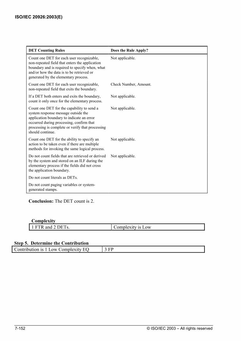
ISO/IEC 20926:2003(E)
7-152 © ISO/IEC 2003 – All rights reserved
DET Counting Rules Does the Rule Apply?
Count one DET for each user recognizable, non-repeated field that enters the application boundary and is required to specify when, what and/or how the data is to be retrieved or generated by the elementary process.
Not applicable.
Count one DET for each user recognizable, non-repeated field that exits the boundary.
Check Number, Amount.
If a DET both enters and exits the boundary, count it only once for the elementary process.
Not applicable.
Count one DET for the capability to send a system response message outside the application boundary to indicate an error occurred during processing, confirm that processing is complete or verify that processing should continue.
Not applicable.
Count one DET for the ability to specify an action to be taken even if there are multiple methods for invoking the same logical process.
Not applicable.
Do not count fields that are retrieved or derived by the system and stored on an ILF during the elementary process if the fields did not cross the application boundary.
Not applicable.
Do not count literals as DETs.
Do not count paging variables or system-generated stamps.
Conclusion: The DET count is 2.
Complexity 1 FTR and 2 DETs. Complexity is Low
Step 5. Determine the Contribution Contribution is 1 Low Complexity EQ 3 FP

ISO/IEC 20926:2003(E)
© ISO/IEC 2003 – All rights reserved 7-153
Summary of EQs, FTRs and DETs Counted
This section gives a summary of the EQs, FTRs, and DETs counted before
calculating the complexity and contribution to the unadjusted function point count.
Summary of EQs Counted
The following table shows the EQs counted for the HR application. It also lists the data that was not counted.
EQs Counted Not Counted
List of retrieved data Application menus Drop-down list box Second occurrence of field help Field level help first occurrence Implied inquiry (previously counted) Monthly Membership Report Check Transaction File
Summary FTR/DET Count
The FTR and DET counts are recorded in the following table.
External Inquiry FTRs DETs List of retrieved data 1 4 Drop-down list box 1 2 Field level help first occurrence 1 6 Weekly Membership Report 1 3 Check Transaction File 1 2

ISO/IEC 20926:2003(E)
7-154 © ISO/IEC 2003 – All rights reserved
External Inquiries Complexity and Contribution
This last section of the EQ examples shows the final steps to determine EQ
complexity and contribution to the unadjusted function point count.
The final steps are as follows:
1. Rate the EQ complexity.
2. Translate the complexity to unadjusted function points.
3. Calculate the external inquiries' contribution to the total unadjusted function point count.
Rate EQ Complexity
The following complexity matrix rates the EQ complexity.
0 to 5 DETs 6 to 19 DETs 20 or more DETs
0 to 1 FTR Low Low Average
2 to 3 FTRs Low Average High
4 or more FTRs Average High High
Legend:
FTR = File Type Referenced (Combination of input and output side)
DET = Data Element Type (Combination of input and output side)

ISO/IEC 20926:2003(E)
© ISO/IEC 2003 – All rights reserved 7-155
Functional Complexity: The following table shows the functional
complexity for each EQ.
External Inquiry
FTRs
DETs
Functional Complexity
List of retrieved data
1 4 Low
Drop-down list box 1 2 Low Field level help 1 6 Low Weekly Membership Report
1 3 Low
Daily Check File 1 2 Low Translate EQs
The following table translates the external inquiries' functional complexity to unadjusted function points.
Functional Complexity Rating Unadjusted Function Points
Low 3
Average 4
High 6
The complexity is recorded in the table in the following section.

ISO/IEC 20926:2003(E)
7-156 © ISO/IEC 2003 – All rights reserved
Calculate EQ Contribution
The following table shows the total contribution for the EQ function type.
Function Type
Functional Complexity
Complexity Totals
Function Types Totals
EQ 5 Low X 3 = 15
Average X 4 =
High X 6 =
15
This total will be recorded on a table that lists all the function types. The final total for all function types is the unadjusted function point count.
The Appendix includes a table to record the totals for all the function types.

ISO/IEC 20926:2003(E)
© ISO/IEC 2003 – All rights reserved 8-1
Determine Type of Count
8 DetermineValue Adjustment Factor (Optional)
Count Data
Functions
Count Transactional
Functions
Identify Counting Scope and Application
Boundary
Introduction This chapter explains the value adjustment factor for the function point count. Contents This chapter includes the following sections:
Topic See Page
Value Adjustment Factor Determination 8-3
Procedures to Determine the VAF 8-3
General System Characteristics 8-4
Degrees of Influence 8-5
Guidelines to Determine Degree of Influence 8-6
1. Data Communications 8-6
2. Distributed Data Processing 8-7
3. Performance 8-8
4. Heavily Used Configuration 8-9
5. Transaction Rate 8-10
6. Online Data Entry 8-10
7. End-User Efficiency 8-11
8. Online Update 8-12
Continued on next page

ISO/IEC 20926:2003(E)
8-2 © ISO/IEC 2003 – All rights reserved
Topic See Page
9. Complex Processing 8-13
10. Reusability 8-14
11. Installation Ease 8-15
12. Operational Ease 8-16
13. Multiple Sites 8-17
14. Facilitate Change 8-18
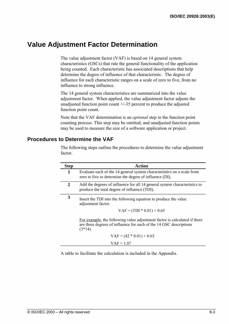
ISO/IEC 20926:2003(E)
© ISO/IEC 2003 – All rights reserved 8-3
Value Adjustment Factor Determination
The value adjustment factor (VAF) is based on 14 general system characteristics (GSCs) that rate the general functionality of the application being counted. Each characteristic has associated descriptions that help determine the degree of influence of that characteristic. The degree of influence for each characteristic ranges on a scale of zero to five, from no influence to strong influence.
The 14 general system characteristics are summarized into the value adjustment factor. When applied, the value adjustment factor adjusts the unadjusted function point count +/-35 percent to produce the adjusted function point count.
Note that the VAF determination is an optional step in the function point counting process. This step may be omitted, and unadjusted function points may be used to measure the size of a software application or project.
Procedures to Determine the VAF The following steps outline the procedures to determine the value adjustment
factor.
Step Action 1 Evaluate each of the 14 general system characteristics on a scale from
zero to five to determine the degree of influence (DI).
2 Add the degrees of influence for all 14 general system characteristics to produce the total degree of influence (TDI).
3 Insert the TDI into the following equation to produce the value adjustment factor.
VAF = (TDI * 0.01) + 0.65
For example, the following value adjustment factor is calculated if there are three degrees of influence for each of the 14 GSC descriptions (3*14). VAF = (42 * 0.01) + 0.65
VAF = 1.07 A table to facilitate the calculation is included in the Appendix.

ISO/IEC 20926:2003(E)
8-4 © ISO/IEC 2003 – All rights reserved
General System Characteristics
The general system characteristics are a set of 14 questions that evaluate the overall complexity of the application.
The 14 general system characteristics are:
1. Data Communications 2. Distributed Data Processing 3. Performance 4. Heavily Used Configuration 5. Transaction Rate 6. Online Data Entry 7. End-User Efficiency 8. Online Update 9. Complex Processing 10. Reusability 11. Installation Ease 12. Operational Ease 13. Multiple Sites 14. Facilitate Change

ISO/IEC 20926:2003(E)
© ISO/IEC 2003 – All rights reserved 8-5
Degrees of Influence
Based on the stated user requirements, each general system characteristic (GSC) must be evaluated in terms of its degree of influence (DI) on a scale of zero to five:
0 Not present, or no influence
1 Incidental influence
2 Moderate influence
3 Average influence
4 Significant influence
5 Strong influence throughout
Each of the following general system characteristic descriptions includes guidelines to determine the degree of influence. The remaining sections in this chapter explain the guidelines for each general system characteristic.

ISO/IEC 20926:2003(E)
8-6 © ISO/IEC 2003 – All rights reserved
Guidelines to Determine Degree of Influence This section presents the guidelines to determine the degree of influence for
each general system characteristic.
The Score As in the tables in this section are guides. If none of the guideline descriptions fits the application exactly, a judgment must be made to determine which degree of influence is the most appropriate for the application.
1. Data Communications Data Communications describes the degree to which the application
communicates directly with the processor.
The data and control information used in the application are sent or received over communication facilities. Terminals connected locally to the control unit are considered to use communication facilities. Protocol is a set of conventions which permit the transfer or exchange of information between two systems or devices. All data communication links require some type of protocol.
Score As Descriptions to Determine Degree of Influence
0 Application is pure batch processing or a stand-alone PC.
1 Application is batch but has remote data entry or remote printing.
2 Application is batch but has remote data entry and remote printing.
3 Application includes online data collection or TP (teleprocessing) front end to a batch process or query system.
4 Application is more than a front-end, but supports only one type of TP communications protocol.
5 Application is more than a front-end, and supports more than one type of TP communications protocol.
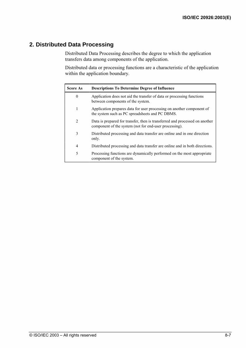
ISO/IEC 20926:2003(E)
© ISO/IEC 2003 – All rights reserved 8-7
2. Distributed Data Processing Distributed Data Processing describes the degree to which the application
transfers data among components of the application.
Distributed data or processing functions are a characteristic of the application within the application boundary.
Score As Descriptions To Determine Degree of Influence
0 Application does not aid the transfer of data or processing functions between components of the system.
1 Application prepares data for user processing on another component of the system such as PC spreadsheets and PC DBMS.
2 Data is prepared for transfer, then is transferred and processed on another component of the system (not for end-user processing).
3 Distributed processing and data transfer are online and in one direction only.
4 Distributed processing and data transfer are online and in both directions.
5 Processing functions are dynamically performed on the most appropriate component of the system.
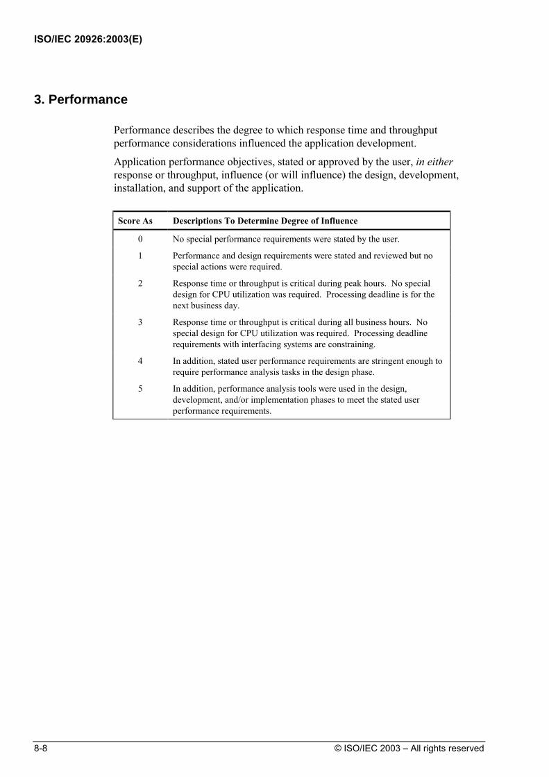
ISO/IEC 20926:2003(E)
8-8 © ISO/IEC 2003 – All rights reserved
3. Performance Performance describes the degree to which response time and throughput
performance considerations influenced the application development.
Application performance objectives, stated or approved by the user, in either response or throughput, influence (or will influence) the design, development, installation, and support of the application.
Score As Descriptions To Determine Degree of Influence
0 No special performance requirements were stated by the user.
1 Performance and design requirements were stated and reviewed but no special actions were required.
2 Response time or throughput is critical during peak hours. No special design for CPU utilization was required. Processing deadline is for the next business day.
3 Response time or throughput is critical during all business hours. No special design for CPU utilization was required. Processing deadline requirements with interfacing systems are constraining.
4 In addition, stated user performance requirements are stringent enough to require performance analysis tasks in the design phase.
5 In addition, performance analysis tools were used in the design, development, and/or implementation phases to meet the stated user performance requirements.

ISO/IEC 20926:2003(E)
© ISO/IEC 2003 – All rights reserved 8-9
4. Heavily Used Configuration Heavily Used Configuration describes the degree to which computer resource
restrictions influenced the development of the application.
A heavily used operational configuration, requiring special design considerations, is a characteristic of the application. For example, the user wants to run the application on existing or committed equipment that will be heavily used.
Score As Descriptions To Determine Degree of Influence
0 No explicit or implicit operational restrictions are included.
1 Operational restrictions do exist, but are less restrictive than a typical application. No special effort is needed to meet the restrictions.
2 Some security or timing considerations are included.
3 Specific processor requirements for a specific piece of the application are included.
4 Stated operation restrictions require special constraints on the application in the central processor or a dedicated processor.
5 In addition, there are special constraints on the application in the distributed components of the system.

ISO/IEC 20926:2003(E)
8-10 © ISO/IEC 2003 – All rights reserved
5. Transaction Rate Transaction Rate describes the degree to which the rate of business
transactions influenced the development of the application.
The transaction rate is high and it influences the design, development, installation, and support of the application.
Score As Descriptions To Determine Degree of Influence
0 No peak transaction period is anticipated.
1 Peak transaction period (e.g., monthly, quarterly, seasonally, annually) is anticipated.
2 Weekly peak transaction period is anticipated.
3 Daily peak transaction period is anticipated.
4 High transaction rate(s) stated by the user in the application requirements or service level agreements are high enough to require performance analysis tasks in the design phase.
5 High transaction rate(s) stated by the user in the application requirements or service level agreements are high enough to require performance analysis tasks and, in addition, require the use of performance analysis tools in the design, development, and/or installation phases.
6. Online Data Entry Online Data Entry describes the degree to which data is entered through
interactive transactions.
Online data entry and control functions are provided in the application.
Score As Descriptions To Determine Degree of Influence
0 All transactions are processed in batch mode.
1 1% to 7% of transactions are interactive data entry.
2 8% to 15% of transactions are interactive data entry.
3 16% to 23% of transactions are interactive data entry.
4 24% to 30% of transactions are interactive data entry.
5 More than 30% of transactions are interactive data entry.
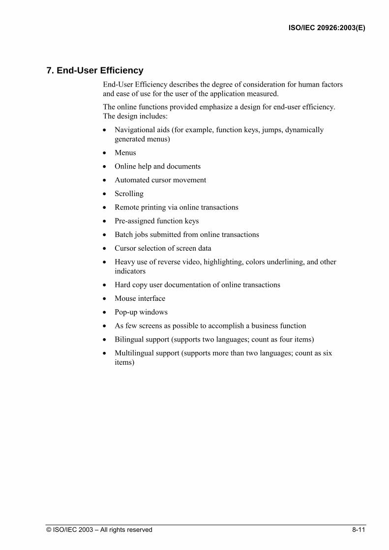
ISO/IEC 20926:2003(E)
© ISO/IEC 2003 – All rights reserved 8-11
7. End-User Efficiency End-User Efficiency describes the degree of consideration for human factors
and ease of use for the user of the application measured.
The online functions provided emphasize a design for end-user efficiency. The design includes:
• Navigational aids (for example, function keys, jumps, dynamically generated menus)
• Menus
• Online help and documents
• Automated cursor movement
• Scrolling
• Remote printing via online transactions
• Pre-assigned function keys
• Batch jobs submitted from online transactions
• Cursor selection of screen data
• Heavy use of reverse video, highlighting, colors underlining, and other indicators
• Hard copy user documentation of online transactions
• Mouse interface
• Pop-up windows
• As few screens as possible to accomplish a business function
• Bilingual support (supports two languages; count as four items)
• Multilingual support (supports more than two languages; count as six items)

ISO/IEC 20926:2003(E)
8-12 © ISO/IEC 2003 – All rights reserved
Score As Descriptions To Determine Degree of Influence
0 None of the above.
1 One to three of the above.
2 Four to five of the above.
3 Six or more of the above, but there are no specific user requirements related to efficiency.
4 Six or more of the above, and stated requirements for end-user efficiency are strong enough to require design tasks for human factors to be included (for example, minimize key strokes, maximize defaults, use of templates).
5 Six or more of the above, and stated requirements for end-user efficiency are strong enough to require use of special tools and processes to demonstrate that the objectives have been achieved.
8. Online Update Online Update describes the degree to which internal logical files are updated
online.
The application provides online update for the internal logical files.
Score As Descriptions To Determine Degree of Influence
0 None.
1 Online update of one to three control files is included. Volume of updating is low and recovery is easy.
2 Online update of four or more control files is included. Volume of updating is low and recovery easy.
3 Online update of major internal logical files is included.
4 In addition, protection against data lost is essential and has been specially designed and programmed in the system.
5 In addition, high volumes bring cost considerations into the recovery process. Highly automated recovery procedures with minimum operator intervention are included.
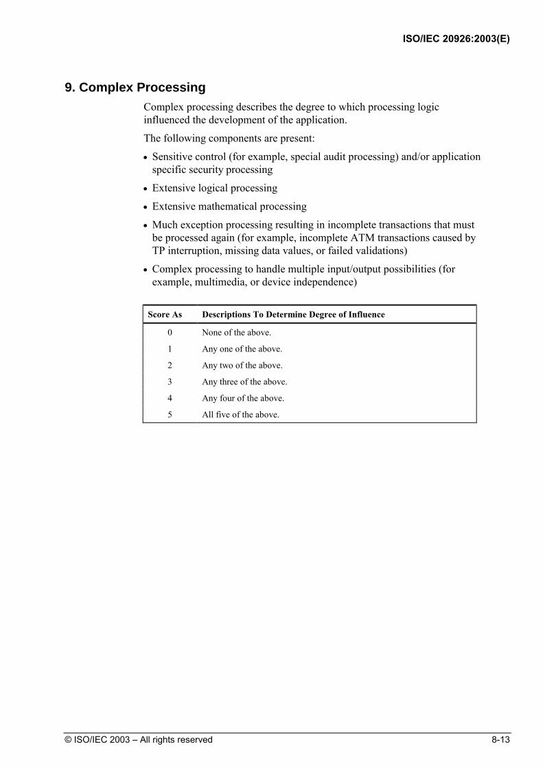
ISO/IEC 20926:2003(E)
© ISO/IEC 2003 – All rights reserved 8-13
9. Complex Processing Complex processing describes the degree to which processing logic
influenced the development of the application.
The following components are present:
• Sensitive control (for example, special audit processing) and/or application specific security processing
• Extensive logical processing
• Extensive mathematical processing
• Much exception processing resulting in incomplete transactions that must be processed again (for example, incomplete ATM transactions caused by TP interruption, missing data values, or failed validations)
• Complex processing to handle multiple input/output possibilities (for example, multimedia, or device independence)
Score As Descriptions To Determine Degree of Influence
0 None of the above.
1 Any one of the above.
2 Any two of the above.
3 Any three of the above.
4 Any four of the above.
5 All five of the above.

ISO/IEC 20926:2003(E)
8-14 © ISO/IEC 2003 – All rights reserved
10. Reusability Reusability describes the degree to which the application and the code in the
application have been specifically designed, developed, and supported to be usable in other applications.
Score As Descriptions To Determine Degree of Influence
0 No reusable code.
1 Reusable code is used within the application.
2 Less than 10% of the application considered more than one user's needs.
3 Ten percent (10%) or more of the application considered more than one user's needs.
4 The application was specifically packaged and/or documented to ease re-use, and the application is customized by the user at source code level.
5 The application was specifically packaged and/or documented to ease re-use, and the application is customized for use by means of user parameter maintenance.

ISO/IEC 20926:2003(E)
© ISO/IEC 2003 – All rights reserved 8-15
11. Installation Ease Installation Ease describes the degree to which conversion from previous
environments influenced the development of the application.
Conversion and installation ease are characteristics of the application. A conversion and installation plan and/or conversion tools were provided and tested during the system test phase.
Score As Descriptions To Determine Degree of Influence
0 No special considerations were stated by the user, and no special setup is required for installation.
1 No special considerations were stated by the user but special setup is required for installation.
2 Conversion and installation requirements were stated by the user, and conversion and installation guides were provided and tested. The impact of conversion on the project is not considered to be important.
3 Conversion and installation requirements were stated by the user, and conversion and installation guides were provided and tested. The impact of conversion on the project is considered to be important.
4 In addition to 2 above, automated conversion and installation tools were provided and tested.
5 In addition to 3 above, automated conversion and installation tools were provided and tested.

ISO/IEC 20926:2003(E)
8-16 © ISO/IEC 2003 – All rights reserved
12. Operational Ease Operational Ease describes the degree to which the application attends to
operational aspects, such as start-up, back-up, and recovery processes.
Operational ease is a characteristic of the application. The application minimizes the need for manual activities, such as tape mounts, paper handling, and direct on-location manual intervention.
Score As Descriptions To Determine Degree of Influence
0 No special operational considerations other than the normal back-up procedures were stated by the user.
1 - 4 One, some, or all of the following items apply to the application. Select all that apply. Each item has a point value of one, except as noted otherwise.
• Effective start-up, back-up, and recovery processes were provided, but operator intervention is required.
• Effective start-up, back-up, and recovery processes were provided, but no operator intervention is required (count as two items).
• The application minimizes the need for tape mounts.
• The application minimizes the need for paper handling.
5 The application is designed for unattended operation. Unattended operation means no operator intervention is required to operate the system other than to start up or shut down the application. Automatic error recovery is a feature of the application.

ISO/IEC 20926:2003(E)
© ISO/IEC 2003 – All rights reserved 8-17
13. Multiple Sites Multiple Sites describes the degree to which the application has been
developed for multiple locations and user organizations.
The application has been specifically designed, developed, and supported to be installed at multiple sites for multiple organizations.
Score As Descriptions To Determine Degree of Influence
0 User requirements do not require considering the needs of more than one user/installation site.
1 Needs of multiple sites were considered in the design, and the application is designed to operate only under identical hardware and software environments.
2 Needs of multiple sites were considered in the design, and the application is designed to operate only under similar hardware and/or software environments.
3 Needs of multiple sites were considered in the design, and the application is designed to operate under different hardware and/or software environments.
4 Documentation and support plan are provided and tested to support the application at multiple sites and the application is as described by 1 or 2.
5 Documentation and support plan are provided and tested to support the application at multiple sites and the application is as described by 3.

ISO/IEC 20926:2003(E)
8-18 © ISO/IEC 2003 – All rights reserved
14. Facilitate Change Facilitate Change describes the degree to which the application has been
developed for easy modification of processing logic or data structure.
The following characteristics can apply for the application:
• Flexible query and report facility is provided that can handle simple requests; for example, and/or logic applied to only one internal logical file (count as one item).
• Flexible query and report facility is provided that can handle requests of average complexity, for example, and/or logic applied to more than one internal logical file (count as two items).
• Flexible query and report facility is provided that can handle complex requests, for example, and/or logic combinations on one or more internal logical files (count as three items).
• Business control data is kept in tables that are maintained by the user with online interactive processes, but changes take effect only on the next business day.
• Business control data is kept in tables that are maintained by the user with online interactive processes, and the changes take effect immediately (count as two items.
Score As Descriptions To Determine Degree of Influence
0 None of the above.
1 A total of one item from above.
2 A total of two items from above.
3 A total of three items from above.
4 A total of four items from above.
5 A total of five items from above.

ISO/IEC 20926:2003(E)
© ISO/IEC 2003 – All rights reserved 9-1
DetermineType of Count
DetermineValue
AdjustmentFactor
CountData
Functions
CountTransactional
FunctionsIdentify
Counting Scope and Application
Boundary
DetermineUnadjusted
FunctionPoint Count
9 CalculateAdjustedFunction
PointCount
Introduction This chapter presents the formulas to complete the last step for function point
analysis. It includes formulas to calculate the three types of function point counts—development project, enhancement project, and application.
Contents This chapter includes the following sections:
Topic See Page
Review of Steps for Function Point Analysis 9-3
Development Project Function Point Calculation 9-4
Application Functionality 9-4
Conversion Functionality 9-4
Application Value Adjustment Factor 9-4
Function Point Formula 9-5
Example: Development Project Function Point Count 9-6
Application Functionality 9-6
Conversion Functionality 9-8
Application Contribution to the Unadjusted Function Point Count
9-9
Continued on next page

ISO/IEC 20926:2003(E)
9-2 © ISO/IEC 2003 – All rights reserved
Topic See Page Conversion Contribution to the Unadjusted Function Point Count
9-10
Final Calculation 9-10
Enhancement Project Function Point Calculation 9-11
Application Functionality 9-11
Conversion Functionality 9-11
Value Adjustment Factor 9-11
Function Point Formula 9-12
Example: Enhancement Project Count 9-13
Application Functionality 9-13
Application Contribution to the Unadjusted Function Point Count
9-14
Final Calculation 9-16
Application Function Point Calculation 9-17
Formula to Establish the Initial Count 9-17
Formula to Reflect Enhancement Projects 9-18
Example: Application Count 9-19
Initial Count 9-19
Count After Enhancement 9-19

ISO/IEC 20926:2003(E)
© ISO/IEC 2003 – All rights reserved 9-3
Review of Steps for Function Point Analysis
The following list includes the function point analysis steps introduced in Chapter 2, Overview of Function Point Analysis.
Step Action
1 Determine the type of function point count (Chapter 4).
2 Identify the counting boundary (Chapter 5).
3 Determine the unadjusted function point count a. Count data functions (Chapter 6). b. Count transactional functions (Chapter 7).
4 Determine the value adjustment factor (Chapter 8). Note that this is an optional step, and that unadjusted function points may be used.
5 Calculate the adjusted function points (Chapter 9). The remaining sections in this chapter present the formulas to complete the
final step to calculate the function point count. Example calculations are included for each of the three types of function points counts:
• Development project
• Enhancement project
• Application
The formulas in this chapter may be used whether or not the value adjustment factor has been calculated. VAF is the value adjustment factor (if the value adjustment factor was not calculated, VAF is 1.00 then the result of the calculation is functional size, reported with units of 'unadjusted function points'. If the VAF is calculated then the result is reported with units of 'adjusted function points').

ISO/IEC 20926:2003(E)
9-4 © ISO/IEC 2003 – All rights reserved
Development Project Function Point Calculation
The development project function point calculation consists of three components of functionality:
• Application functionality included in the user requirements for the project
• Conversion functionality included in the user requirements for the project
• Application value adjustment factor
Application Functionality Application functionality consists of functions used after software installation
to satisfy the ongoing business needs of the user.
Conversion Functionality Conversion functionality consists of functions provided only at installation to
convert data and/or provide other user-specified conversion requirements, such as special conversion reports.
For example, if a Human Resources (HR) software application was in use and a new HR application is installed, the users may require that information about employees be converted and loaded into the new application. The user-specified conversion requirement is to transfer the current employee data into the new HR system.
Application Value Adjustment Factor The value adjustment factor, if used, is determined by using the 14 general
system characteristics to rate the application functional complexity. Refer to Chapter 8 for details.
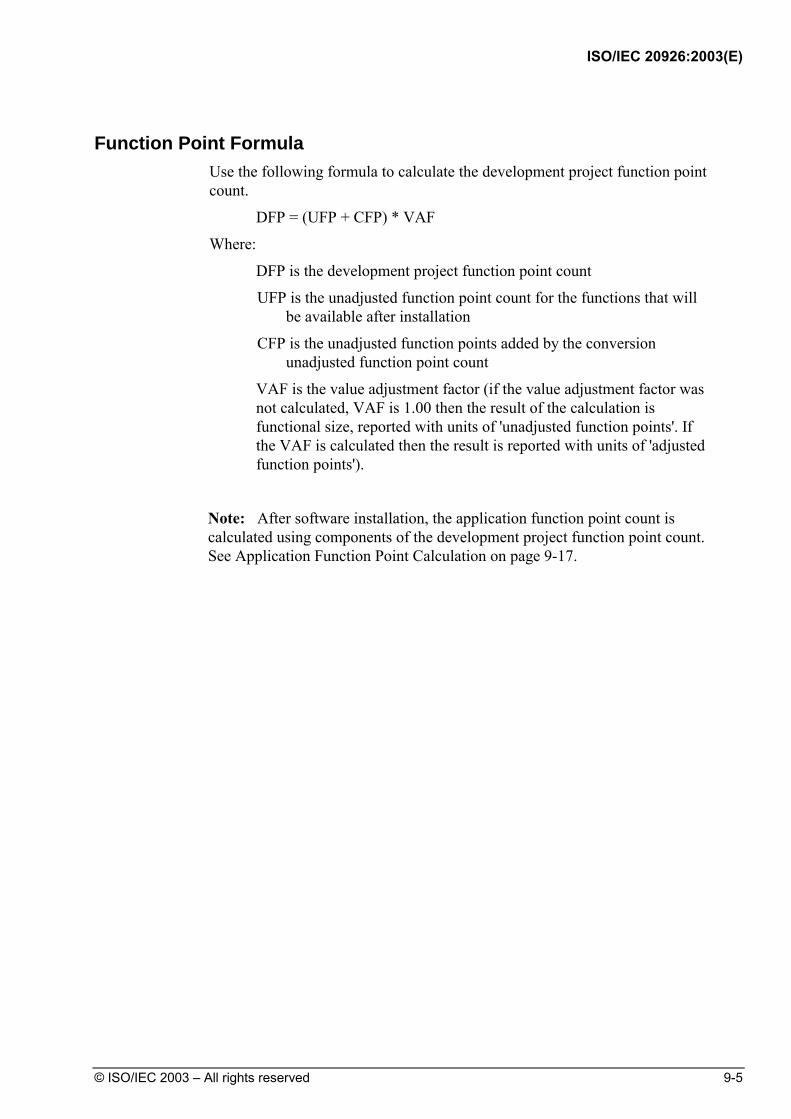
ISO/IEC 20926:2003(E)
© ISO/IEC 2003 – All rights reserved 9-5
Function Point Formula Use the following formula to calculate the development project function point
count.
DFP = (UFP + CFP) * VAF
Where:
DFP is the development project function point count
UFP is the unadjusted function point count for the functions that will be available after installation
CFP is the unadjusted function points added by the conversion unadjusted function point count
VAF is the value adjustment factor (if the value adjustment factor was not calculated, VAF is 1.00 then the result of the calculation is functional size, reported with units of 'unadjusted function points'. If the VAF is calculated then the result is reported with units of 'adjusted function points').
Note: After software installation, the application function point count is calculated using components of the development project function point count. See Application Function Point Calculation on page 9-17.
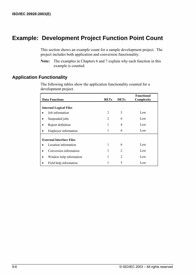
ISO/IEC 20926:2003(E)
9-6 © ISO/IEC 2003 – All rights reserved
Example: Development Project Function Point Count
This section shows an example count for a sample development project. The project includes both application and conversion functionality.
Note: The examples in Chapters 6 and 7 explain why each function in this example is counted.
Application Functionality The following tables show the application functionality counted for a
development project.
Data Functions
RETs
DETs
Functional Complexity
Internal Logical Files
• Job information 2 5 Low
• Suspended jobs 2 6 Low
• Report definition
• Employee information
1
1
4
6
Low
Low
External Interface Files
• Location information 1 6 Low
• Conversion information 1 2 Low
• Window help information 1 2 Low
• Field help information 1 5 Low

ISO/IEC 20926:2003(E)
© ISO/IEC 2003 – All rights reserved 9-7
Transactional Functions
FTRs
DETs
Functional Complexity
External Inputs
Assignment report definition 1 5 Low
Add job information (screen input) 1 7 Low
Add job information (batch input) 2 6 Average
Correct suspended jobs 1 7 Low
Employee job assignment 3 7 High
EI with screen output –1 2 11 Average
EI with screen output –2 1 6 Low
External Outputs
Jobs with employees report 4 5 Average
Employees by assignment duration report 3 7 Average
Performance review notification 3 4 Low
Weekly employees report 1 3 Low
Printed check 1 3 Low
Check transaction file 1 4 Low
External Inquiries
List of retrieved data 1 4 Low
Drop-down list box 1 2 Low
Field level help 1 6 Low
Weekly membership report 1 3 Low
Daily check file 1 2 Low

ISO/IEC 20926:2003(E)
9-8 © ISO/IEC 2003 – All rights reserved
Conversion Functionality The following table shows the conversion functionality for the development
project.
Transactional Function
FTRs
DETs
Functional Complexity
External Input
Employee migration 1 11 Low
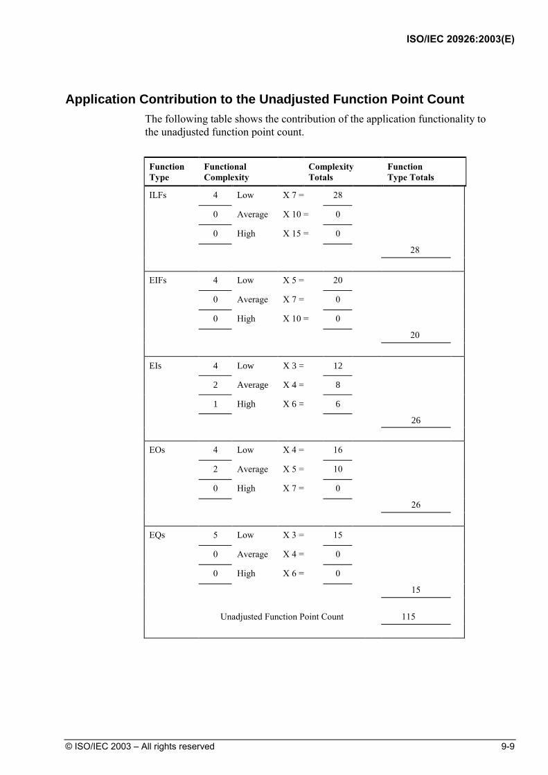
ISO/IEC 20926:2003(E)
© ISO/IEC 2003 – All rights reserved 9-9
Application Contribution to the Unadjusted Function Point Count The following table shows the contribution of the application functionality to
the unadjusted function point count.
Function Type
Functional Complexity
Complexity Totals
Function Type Totals
ILFs 4 Low X 7 = 28 0 Average X 10 = 0 0 High X 15 = 0 28 EIFs 4 Low X 5 = 20 0 Average X 7 = 0 0 High X 10 = 0 20 EIs 4 Low X 3 = 12
2 Average X 4 = 8
1 High X 6 = 6
26
EOs 4 Low X 4 = 16
2 Average X 5 = 10
0 High X 7 = 0
26 EQs 5 Low X 3 = 15
0 Average X 4 = 0
0 High X 6 = 0
15 Unadjusted Function Point Count 115

ISO/IEC 20926:2003(E)
9-10 © ISO/IEC 2003 – All rights reserved
Conversion Contribution to the Unadjusted Function Point Count The following table shows the contribution of the conversion functionality to
the unadjusted function point count.
Function Type
Functional Complexity
Complexity Totals
Function Type Totals
EIs 1 Low X 3 = 3
0 Average X 4 = 0
0 High X 6 = 0
Unadjusted Function Point Count 3
Final Calculation Using the complexity and contribution counts for this example, the
development project count is shown below. The value adjustment factor for this example is 1.05. (The formula was explained on page 9-5.)
DFP = (UFP + CFP) * VAF
DFP = (115 + 3) * 1.05
DFP = 123.9 or 124

ISO/IEC 20926:2003(E)
© ISO/IEC 2003 – All rights reserved 9-11
Enhancement Project Function Point Calculation
The enhancement project function point calculation consists of three components of functionality:
• Application functionality included in the user requirements for the project
• Conversion functionality included in the user requirements for the project
• Application value adjustment factor
Application Functionality Application functionality consists of:
• Function points identified from the functionality that is added by the enhancements
• Function points counted because existing functionality is changed during the enhancement project
• Function points counted for functionality deleted during the enhancement project
Conversion Functionality The conversion functionality consists of function points delivered because of
any conversion functionality required by the user.
Value Adjustment Factor The two value adjustment factors are the:
• Application value adjustment factor before the enhancement project begins
• Application value adjustment factor after the enhancement project is complete
Note that if the value adjustment factors were not calculated, each will be assumed to be 1.00.
VAF is the value adjustment factor (if the value adjustment factor was not calculated, VAF is 1.00 then the result of the calculation is functional size, reported with units of 'unadjusted function points'. If the VAF is calculated then the result is reported with units of 'adjusted function points').

ISO/IEC 20926:2003(E)
9-12 © ISO/IEC 2003 – All rights reserved
Function Point Formula Use the following formula to calculate the enhancement project function point
count.
Note: Data conversion requirements are included in this count.
EFP = [(ADD + CHGA + CFP) * VAFA] + (DEL* VAFB)
Where:
EFP is the enhancement project function point count.
ADD is the unadjusted function point count of those functions that were or will be added by the enhancement project.
CHGA is the unadjusted function point count of those functions that were or will be modified by the enhancement project. This number reflects the size of the functions after the modifications.
CFP is the function point count of those functions added by the conversion
VAFA is the value adjustment factor of the application after the enhancement project is complete. (If VAFA was not calculated, it will be assumed to be 1.00.)
DEL is the unadjusted function point count of those functions that were or will be deleted by the enhancement project.
VAFB is the value adjustment factor of the application before the enhancement project begins. (If VAFB was not calculated, it will be assumed to be 1.00.)
Note: VAF is the value adjustment factor (if the value adjustment factor was not calculated, VAF is 1.00 then the result of the calculation is functional size, reported with units of 'unadjusted function points'. If the VAF is calculated then the result is reported with units of 'adjusted function points').
Note: When an enhancement project is installed, the application function point count must be updated to reflect changes in the application's functionality.
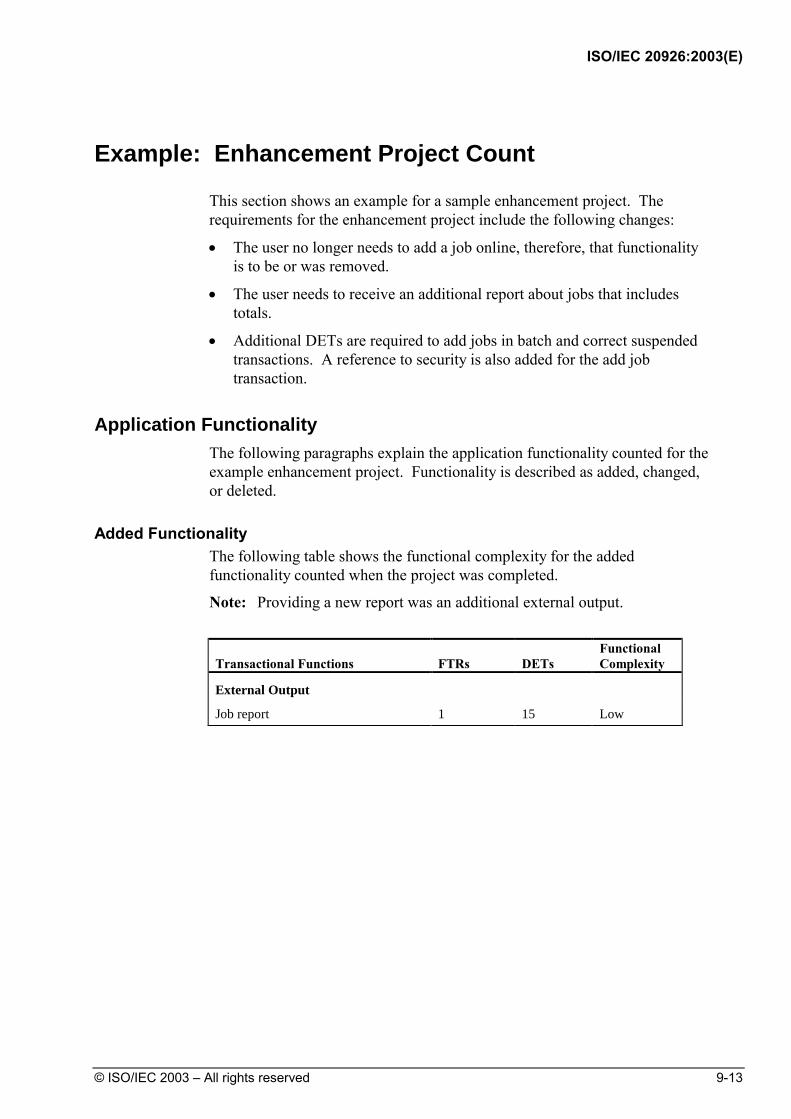
ISO/IEC 20926:2003(E)
© ISO/IEC 2003 – All rights reserved 9-13
Example: Enhancement Project Count
This section shows an example for a sample enhancement project. The requirements for the enhancement project include the following changes:
• The user no longer needs to add a job online, therefore, that functionality is to be or was removed.
• The user needs to receive an additional report about jobs that includes totals.
• Additional DETs are required to add jobs in batch and correct suspended transactions. A reference to security is also added for the add job transaction.
Application Functionality The following paragraphs explain the application functionality counted for the
example enhancement project. Functionality is described as added, changed, or deleted.
Added Functionality The following table shows the functional complexity for the added
functionality counted when the project was completed.
Note: Providing a new report was an additional external output.
Transactional Functions
FTRs
DETs
Functional Complexity
External Output
Job report 1 15 Low
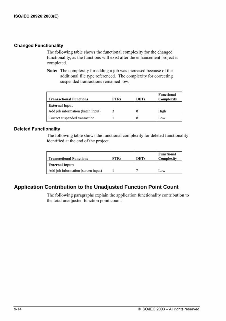
ISO/IEC 20926:2003(E)
9-14 © ISO/IEC 2003 – All rights reserved
Changed Functionality The following table shows the functional complexity for the changed
functionality, as the functions will exist after the enhancement project is completed.
Note: The complexity for adding a job was increased because of the additional file type referenced. The complexity for correcting suspended transactions remained low.
Transactional Functions
FTRs
DETs
Functional Complexity
External Input
Add job information (batch input) 3 8 High
Correct suspended transaction 1 8 Low
Deleted Functionality The following table shows the functional complexity for deleted functionality
identified at the end of the project.
Transactional Functions
FTRs
DETs
Functional Complexity
External Inputs
Add job information (screen input) 1 7 Low
Application Contribution to the Unadjusted Function Point Count The following paragraphs explain the application functionality contribution to
the total unadjusted function point count.

ISO/IEC 20926:2003(E)
© ISO/IEC 2003 – All rights reserved 9-15
Added Functionality The following table shows the contribution to the unadjusted function point
count for the added functionality identified at the end of the project.
Function Type
Functional Complexity
Complexity Totals
Function Type Totals
EOs 1 Low X 4 = 4 0 Average X 5 = 0 0 High X 7 = 0 4
Changed Functionality The following table shows the contribution to the unadjusted function point
count for the changed functionality as it will exist after the enhancement project is complete.
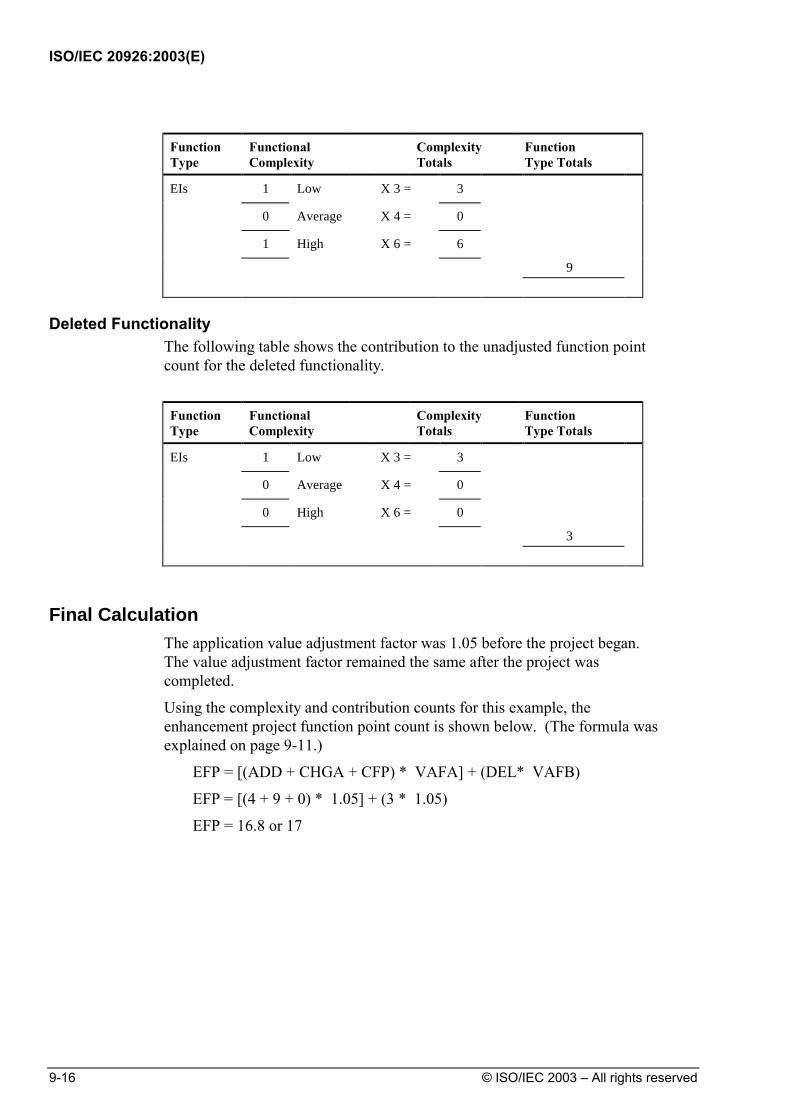
ISO/IEC 20926:2003(E)
9-16 © ISO/IEC 2003 – All rights reserved
Function Type
Functional Complexity
Complexity Totals
Function Type Totals
EIs 1 Low X 3 = 3
0 Average X 4 = 0
1 High X 6 = 6
9
Deleted Functionality The following table shows the contribution to the unadjusted function point
count for the deleted functionality.
Function Type
Functional Complexity
Complexity Totals
Function Type Totals
EIs 1 Low X 3 = 3
0 Average X 4 = 0
0 High X 6 = 0
3
Final Calculation The application value adjustment factor was 1.05 before the project began.
The value adjustment factor remained the same after the project was completed.
Using the complexity and contribution counts for this example, the enhancement project function point count is shown below. (The formula was explained on page 9-11.)
EFP = [(ADD + CHGA + CFP) * VAFA] + (DEL* VAFB)
EFP = [(4 + 9 + 0) * 1.05] + (3 * 1.05)
EFP = 16.8 or 17
ISO/IEC 20926:2003(E)
© ISO/IEC 2003 – All rights reserved 9-17
Application Function Point Calculation
This section provides the formulas to calculate the application function point count. There are two variations of this formula:
• Formula to establish the initial function point count for an application
• Formula to re-establish the function point count for an application after an enhancement project has changed the application functionality
Formula to Establish the Initial Count Use the formula in this section to establish the initial function point count for
an application. Initially, the user is receiving new functionality. There are no changes to the existing functionality or deletions of obsolete or unneeded functionality. The application function point count does not include conversion requirements.
AFP = ADD * VAF
Where:
AFP is the initial application function point count.
ADD is the unadjusted function point count of those functions that were installed by the development project.
VAF is the value adjustment factor (if the value adjustment factor was not calculated, VAF is 1.00 then the result of the calculation is functional size, reported with units of 'unadjusted function points'. If the VAF is calculated then the result is reported with units of 'adjusted function points').

ISO/IEC 20926:2003(E)
9-18 © ISO/IEC 2003 – All rights reserved
Formula to Reflect Enhancement Projects When an enhancement project is installed, the existing application function point count must
be updated to reflect modifications to the application. The functionality for the application can be altered in one or more ways:
• Added (new) functionality increases the size of the application
• Changed functionality increases, decreases, or has no effect on the size of the application
• Deleted functionality decreases the application size
• Changes to the value adjustment factor adds, subtracts, or has no effect on the function point count but does affect the adjusted function point count
Note: Because conversion functionality does not affect the application function point count, any conversion functionality associated with an enhancement project is omitted entirely from the application function point calculation.
Note: VAF is the value adjustment factor (if the value adjustment factor was not calculated, VAF is 1.00 then the result of the calculation is functional size, reported with units of 'unadjusted function points'. If the VAF is calculated then the result is reported with units of 'adjusted function points').
Use the following formula to calculate the application function point count after an enhancement project:
AFP = [(UFPB + ADD + CHGA) - (CHGB + DEL)] * VAFA
Where:
AFP is the application's adjusted function point count.
UFPB is the application's unadjusted function point count before the enhancement project begins.
Note: If this count is unavailable, it can be calculated using the formula UFBP = AFPB/VAFB; where AFPB is the adjusted application function point count before the enhancement project. VAFB is the value adjustment factor of the application before the enhancement project.
ADD is the unadjusted function point count of those functions that were added by the enhancement project.
CHGA is the unadjusted function point count of those functions that were changed by the enhancement project. This number reflects the size of the functions after the changes.
CHGB is the unadjusted function point count of those functions that were changed by the enhancement project. This number reflects the size of the functions before the changes were made.
DEL is the unadjusted function point count of those functions that were deleted by the enhancement project.
VAFA is the value adjustment factor of the application after the enhancement project is complete. (If VAFA was not calculated, it will be assumed to be 1.00.)
ISO/IEC 20926:2003(E)
© ISO/IEC 2003 – All rights reserved 9-19
Example: Application Count
This section shows an example for the initial count and the count that reflects an enhancement project. Numbers for these counts are from the application count on page 9-8 and the enhancement count on page 9-11.
Initial Count The initial application project count is shown below. The value adjustment
factor is 1.05. (The formula was explained on page 9-17.)
AFP = ADD * VAF
AFP = 115 * 1.05
AFP = 120.75 or 121
Note: Only the size of the application functionality installed for the user is included in the initial count.
Count After Enhancement The application project function point count to reflect enhancements is shown
below. The value adjustment factor is 1.05. (The formula was explained on page 9-18.)
AFP = [(UFPB + ADD + CHGA) - (CHGB + DEL)]* VAFA
AFP = [(115 + 4 + 9) - (9 + 3)]* 1.05
AFP = 121.8 or 122

ISO/IEC 20926:2003(E)
9-20 © ISO/IEC 2003 – All rights reserved
(Blank page)

ISO/IEC 20926:2003(E)
© ISO/IEC 2003 – All rights reserved A-1
Appendix A: Calculation Tables
Introduction Appendix A includes tables to facilitate counting function points. Contents This appendix includes the following tables:
Topic See Page Unadjusted Function Point Count Calculation Table A-2
Value Adjustment Factor Calculation Table A-3

ISO/IEC 20926:2003(E)
A-2 © ISO/IEC 2003 – All rights reserved
Unadjusted Function Point Count Calculation Table
The following table is provided to facilitate the calculation of the contribution to the unadjusted function point count.
Function Type
Functional Complexity
Complexity Totals
Function Type Totals
ILFs Low X 7 = Average X 10 = High X 15 = EIFs Low X 5 = Average X 7 = High X 10 = EIs Low X 3 =
Average X 4 =
High X 6 =
EOs Low X 4 =
Average X 5 =
High X 7 =
EQs Low X 3 =
Average X 4 =
High X 6 =
Total Unadjusted Function Point Count

ISO/IEC 20926:2003(E)
© ISO/IEC 2003 – All rights reserved A-3
Value Adjustment Factor Calculation Table
The following table is provided to facilitate the calculation of the value adjustment factor.
General System Characteristics (GSCs) Degree of Influence (DI) 0 - 5
1. Data Communications
2. Distributed Data Processing
3. Performance
4. Heavily Used Configuration
5. Transaction Rate
6. Online Data Entry
7. End-User Efficiency
8. Online Update
9. Complex Processing
10. Reusability
11. Installation Ease
12. Operational Ease
13. Multiple Sites
14. Facilitate Change
Total Degree of Influence (TDI)
Value Adjustment Factor (VAF)
VAF = (TDI * 0.01) + 0.65

ISO/IEC 20926:2003(E)
A-4 © ISO/IEC 2003 – All rights reserved
(Blank page)

ISO/IEC 20926:2003(E)
© ISO/IEC 2003 – All rights reserved B-1
Appendix B: The Change from CPM 4.0 to 4.1
Introduction This appendix includes information about the changes, clarifications, and enhancements in CPM 4.1, the decision making process, and recommendations to users of the new manual.
Contents This chapter includes the following:
Topic See Page
Introduction B-2
Major Functional Change Areas in CPM 4.1 B-2
Version Control B-3
Overview of Changes B-4
Background B-8
The Impact Study B-8
Conversion from CPM 4.0 to 4.1 B-9
Impact on 4.0 Users Changing to 4.1 B-10
Recommendations B-10
ISO/IEC 20926:2003(E)
B-2 © ISO/IEC 2003 – All rights reserved
Introduction
Since the release of IFPUG Counting Practices Manual (CPM) 4.0 in January 1994, the Counting Practices Committee (CPC) has received requests from the membership to clarify existing rules or to include topics the members felt were not adequately covered by CPM 4.0 including: • the identification of elementary processes, • the identification of external inputs (EIs), external outputs (EOs), and external inquiries
(EQs), and • counting Data Element Types (DETs) for transactional and data function types. In creating CPM 4.1, following the CPM revision process, the CPC has reviewed all requests for support and, where appropriate, new rules have been promulgated, and existing rules clarified. Also, new hints and examples have been included to aid understanding. When revising the CPM, the CPC process is as follows: 1. The issue is submitted to the CPC by the membership. 2. The issue is assigned to CPC members for research. 3. The CPC reviews and discusses the issue. 4. The CPC presents the proposed solution to the membership. 5. An impact study is initiated. 6. The final decision is made. 7. The IFPUG membership is informed of the decision through MetricViews and IFPUG conference
presentations. 8. Changes become effective in a new CPM. 9. Case Studies are revised to reflect the new CPM. The CPC believes that CPM 4.1’s expanded and clarified definitions, examples, and hints will insure more consistent results between Certified Function Point Specialists.
Major Functional Change Areas in CPM 4.1
The major functional change areas in CPM 4.1 are: • New chapter - Guidance on counting function points from the “user’s view” • Guidance on establishing the application boundary • Guidance on identifying elementary process • Identification of DETs for data function types (Internal Logical Files (ILFs)/External Interface
Files (EIFs)) and transactional function types (EI/EO/EQ) • Differentiation between EOs and EQs • Clarification on control information • Clarification of shared ILF/EIFs

ISO/IEC 20926:2003(E)
© ISO/IEC 2003 – All rights reserved B-3
Version Control
The CPC has chosen to name this version of the IFPUG CPM 4.1 rather than 5.0 for two reasons: • CPM 4.1 is not a major change from the Albrecht methodology that forms the basis of all
previous IFPUG CPMs. It is, for the most part, a refinement and clarification of the previous manual.
• The impact study performed to compare counts using CPM 4.0 and 4.1 showed very little difference in the functional size of the projects when measured using both methods. The count results compared in this study indicated that the counts are comparable and that an adjustment of counts previously done using 4.0 is unnecessary in the majority of cases. Therefore, there was no need to indicate by version number that these counts are not comparable, and there will be no noticeable change to organizations’ software assets portfolio
ISO/IEC 20926:2003(E)
B-4 © ISO/IEC 2003 – All rights reserved
Overview of Changes
Many revisions and enhancements have been made in this new version of the CPM and are listed below by chapter.
Chapter 1: Introduction This chapter is unchanged.
Chapter 2: Overview of Function Point Analysis This chapter now introduces the concept of the primary intent of a function type to assist in identification of EIs, EOs, and EQs.
Chapter 3: User View This new chapter presents the concept of the user’s role in defining the functional requirements for a project or application by defining user view and discussing sizing during the life cycle of an application by phases.
Chapter 4: Determine the Type of Count This chapter was previously chapter 3 and is unchanged.
Chapter 5: Identify Counting Scope and Application Boundary This chapter was previously chapter 4, Identify Counting Boundary, and now defines the terms: purpose of the count, counting scope, and application boundary. It includes rules, procedures, and hints to determine boundaries for applications and to establish the scope of the count.
ISO/IEC 20926:2003(E)
© ISO/IEC 2003 – All rights reserved B-5
Chapter 6: Count Data Functions This was previously chapter 5, Count Data Function Types. The important clarifications and revisions to the definitions and rules used to identify Data Element Types (DETs) and File Types References (FTRs) for data function types are: • When two applications maintain the same ILF/EIF, but each maintain separate portions of the
available DETs, only the information being used by each application being counted should be used to size the ILF/EIF. Each application counts the key(s) as DETs, regardless of whether each can maintain those data elements.
• If an application references a logical data file for one portion of the data, yet maintains the logical data file for a different portion of the data, the combination of the DETs that are maintained and referenced will be counted as an ILF. A group of data cannot be counted as both an ILF and EIF by the same application.
• Two different applications being counted can count the same sets of information as having a different number of DETs, depending on the user’s view and use of that data.
• A before or after image of a group of 10 fields maintained for audit purposes would count as one DET for the before image (all 10 fields) and one DET for the after image (all 10 fields).
This chapter has also been enhanced by the inclusion of: • a clearer definition of control data, • a new definition for user identifiable, • the descriptions of the primary intent of each transactional function type, • a clarification of DET rules, • new examples for DET rules, • new examples for counting ILFs and EIFs, and • new and enhanced hints.
Chapter 7: Count Transactional Functions This chapter was previously chapter 6, Count Transactional Function Types. The important clarifications and revisions to the definitions or rules used to identify DETs and or FTRs for transactional function types are: • For an EI, count one DET for each user recognizable field that enters or exits the application
boundary and is required to complete the external input. • Only count DETs for those fields that enter or exit the boundary of the application. • Control information can perform as the input side of an EO or EQ. The request specifying
what, when, and/or how data is to be retrieved or generated, is part of the elementary process to provide the user data and is not an elementary process itself.
• Do not count fields that are retrieved or derived by the system and stored on an ILF during the elementary process if the field(s) did not cross the application boundary.
• A process can trigger an “internal process” which may result in an update of information. This overall process is either counted as an EI or EO depending on the primary intent of the process, regardless of the number of “internal processes” that may be triggered.
• An EO or EQ can be triggered without data crossing the boundary by a process inside the application boundary.
• An elementary process identified as an EO or EQ may have an input side and an output side. • To determine the EO complexity and contribution to the unadjusted function point count:

ISO/IEC 20926:2003(E)
B-6 © ISO/IEC 2003 – All rights reserved
− identify and count the number of FTRs and DETs for the input side of the EO, − identify and count the number of FTRs and DETs for the output side of the EO,
and − combine the contributors to complexity for the input side and the output side,
ignoring duplicates, to determine the overall complexity of the function using the EO complexity matrix.
• To determine the EQ complexity and contribution to the unadjusted function point count: − identify and count the number of FTRs and DETs for the input side of the EQ, − identify and count the number of FTRs and DETs for the output side of the EQ,
and − combine the contributors to complexity for the input side and the output side,
ignoring duplicates, to determine the overall complexity of the function using the EQ complexity matrix.
NOTE: Previously, both the input side and output side of an EQ were compared and the most complex side was chosen to rate the EQ.
This chapter has also been enhanced by the inclusion of: • an expanded index of the chapter, • additional identification rules for elementary processes, • additional and improved examples to assist in identifying unique elementary processes, • descriptions of the primary intent of each transactional function type, • a table summarizing the functions performed by the transactional function types to ease
identification, • a clearer definition of control information, • a refined definition of user, • a new definition for user identifiable, • an enhanced definition and additional examples of processing logic, • a table summarizing the processing logic of each transactional function type to ease
identification, and • examples of fields that are retrieved or derived by the system and are not counted as DETs.
Chapter 8: Determine Value Adjustment Factor This chapter was previously chapter 7 and has been enhanced by the addition of the description of each of the General System Characteristics.
Chapter 9: Calculate Final Adjusted Function Point Count This chapter was previously chapter 8 and is unchanged.
Appendix A: Calculation Tables This appendix is unchanged.
Appendix B: The Change from CPM 4.0 to 4.1 This new chapter includes the following • the major functional change areas in CPM 4.1, • version control information, • an overview of the changes by chapter, • the background of the change process,

ISO/IEC 20926:2003(E)
© ISO/IEC 2003 – All rights reserved B-7
• the impact study process, • the impact of the changes on 4.1 users, • conversion from CPM 4.0 to 4.1, and • recommendations for users switching from 4.0 to 4.1.
Glossary The glossary has been updated to include new and changed definitions.
Quick Reference Card There is a new IFPUG Function Point Quick Reference Card, based on CPM 4.1. This easy to use guide includes: • Steps in FP Analysis, • Key Definition of Terms, • information on counting ILFs, EIFs, EIs, EOs, and EQs, • Weighted Complexity of Functions, • General Systems Characteristics, • Formulas, • Summary of Functions Performed by EIs, EOs, and EQs, and • Summary of Processing Logic Used by EIs, EOs, and EQs.
ISO/IEC 20926:2003(E)
B-8 © ISO/IEC 2003 – All rights reserved
Background
The CPC internal decision making process is governed by a set of CPM characteristics (meta rules) selected and voted on by the IFPUG board and the CPC. Those guiding principles in order of importance are: 1. It should be possible to model the correlation of software size (derived using the CPM) with other
attributes (e.g., effort, defects, cost, etc.). 2. The CPM contains a consistent set of rules. 3. Function Point Analysis results are consistent between different counters using the CPM. 4. The CPM provides rules on how to size a functional need that is defined and agreed upon by
user(s) and IT. 5. Function Point Analysis results using the CPM can be a contributing factor in estimation. 6. The CPM is an Albrecht based method. 7. Function Point Analysis using the CPM is easy. 8. Function Point Analysis using the CPM is fast.
The Impact Study
As required by the CPC revision process, an impact study with 35 participating IFPUG members was conducted to: • assure that the content of the new CPM would enable the membership to identify the changes,
and to correctly interpret and apply them, • determine the change in results of function point counts done using CPM 4.0 and 4.1, and • enable the CPC, based on the change in the results, to recommend to the membership the
conversion factors, or procedures, to be applied to the size of existing 4.0 counts to make them compatible with future counts performed using CPM 4.1, if necessary.
To accomplish this goal, a group of IFPUG members who were Certified Function Point Specialists: • submitted a participant profile detailing their counting experience using CPM 4.0, • participated in a series of controlled test case exercises, based on the proposed CPM changes,
using a draft, experimental version of the new CPM, • provided comments on the proposed changes in the experimental version of the CPM, and • submitted a variety of their own projects counted using both CPM 4.0 and 4.1 for comparison,
along with project profile information. The results of the test case exercises administered in September 1997 and April 1998, assured the CPC that the new CPM did enable the participants to identify the changes, and to correctly interpret and apply them. The CPC then asked the participants to submit their own counted projects, and a project profile for each project submitted, for analysis. Of the projects submitted, 17 qualified for inclusion in the study. The criteria for submitted projects were: • the projects must have been more that 100 function points according to CPM 4.0, • the projects must have been new development or enhancement projects (software installation
projects were excluded), • the projects must have been completed, and
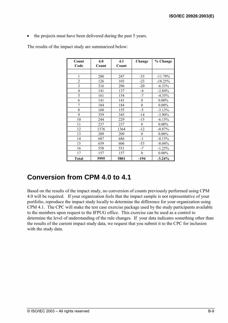
ISO/IEC 20926:2003(E)
© ISO/IEC 2003 – All rights reserved B-9
• the projects must have been delivered during the past 5 years. The results of the impact study are summarized below:
Count Code
4.0 Count
4.1 Count
Change % Change
1 280 247 -33 -11.79% 2 126 103 -23 -18.25% 3 316 296 -20 -6.33% 4 141 137 -4 -2.84% 5 161 154 -7 -4.35% 6 141 141 0 0.00% 7 184 184 0 0.00% 8 160 155 -5 -3.13% 9 359 345 -14 -3.90%
10 244 229 -15 -6.15% 11 237 237 0 0.00% 12 1376 1364 -12 -0.87% 13 209 209 0 0.00% 14 687 686 -1 -0.15% 15 659 606 -53 -8.04% 16 558 551 -7 -1.25% 17 157 157 0 0.00%
Total 5995 5801 -194 -3.24%
Conversion from CPM 4.0 to 4.1
Based on the results of the impact study, no conversion of counts previously performed using CPM 4.0 will be required. If your organization feels that the impact sample is not representative of your portfolio, reproduce the impact study locally to determine the difference for your organization using CPM 4.1. The CPC will make the test case exercise package used by the study participants available to the members upon request to the IFPUG office. This exercise can be used as a control to determine the level of understanding of the rule changes. If your data indicates something other than the results of the current impact study data, we request that you submit it to the CPC for inclusion with the study data.
ISO/IEC 20926:2003(E)
B-10 © ISO/IEC 2003 – All rights reserved
Impact on 4.0 Users Changing to 4.1
The changes in counting practices will result in need for IFPUG committees to review the following documents to assure the conformance of the documents to CPM 4.1: A. all IFPUG documents related to the CPM, B. Case Studies 1, 2, 3, and 4, which will begin in 1999, and C. Management Reporting Guides. Although certification tests will be updated to reflect the changes, recertification from 4.0 to 4.1 will not be required.
Recommendations
The CPC recommends the following actions for users switching from CPM 4.0 to 4.1: • Attend the workshop on the new manual the CPC is providing at the IFPUG Spring 1999
Training Sessions. • Update all in-house developed training materials for conformance. • Ensure all counters within your organization have been appropriately trained in the
differences between 4.0 and 4.1. • Check all vendor offered training materials for version certification. • Notify anyone in your organization involved with function point counts of the change and
make the new manual available to them. • Review all counting tools for your users, both automated and manual, for IFPUG 4.0 version
certification, if applicable, and modifications to conform to 4.1 counting rules. • Although an additional certification will not be required for counters for CPM 4.1, the
certification tests will be updated for conformance to 4.1 during 1999. • Specify on the documentation for each function point count done, and with the results, which
version of the CPM was used for the count. • Make sure to specify which version of the IFPUG CPM was used for counting when
submitting data for benchmarking either to your own benchmark database, the IFPUG Benchmarking committee, or ISBSG.
• Update all internal guidelines and other local documents related to 4.0 to version 4.1.

ISO/IEC 20926:2003(E)
© ISO/IEC 2003 – All rights reserved Index-1
Index A Adjusted function point count
application, 9-17 development project, 9-4 enhancement project, 9-11 overview, 2-9
Albrecht 1984, 1-2 Alternate index example, 6-42 Application
data counting example, 6-21 example count, 9-19 formula, 9-17 function point count, 4-2 menus counting example, 7-127 value adjustment factor, 9-4, 8-3
Audit data for inquiries and reports, 6-34 B Batch with multiple and duplicate EIs, 7-62 Boundary
definition, 5-4 diagram, 5-4 hints, 5-6 overview, 2-5 procedures, 5-5 purpose, 5-2 rules, 5-5
C Calculations
application, 9-17 conversion functionality, 9-4, 9-11
development project, 9-4 enhancement project, 9-11 function point analysis, 9-3 value adjustment factor, 8-3
CIS & A Guidelines 313, 1-2 Complex processing, 8-13 Complexity and contribution procedures
external inputs, 7-21 external inquiries, 7-32 external interface files, 6-11 external outputs, 7-22 internal logical files, 6-11
Complexity and contribution rules external inputs, 7-14 external inquiries, 7-16 external interface file, 6-7 external outputs, 7-16 internal logical files rules, 6-7
Complexity matrices external inputs, 7-21 external inquiries, 7-22 external interface files, 6-11 external outputs, 7-22 internal logical files, 6-11
Complexity procedures, See Complexity and contribution procedures Complexity rules, See Complexity and Contribution Confirmation message screen, 7-103 Confirmation messages, 7-103 Contribution rules, See Complexity and contribution Control information
EI example, 7-54 external inputs, 7-5, 7-8 for reporting, 7-54 ILF/EIF example, 6-3
Conversion data model, 6-75
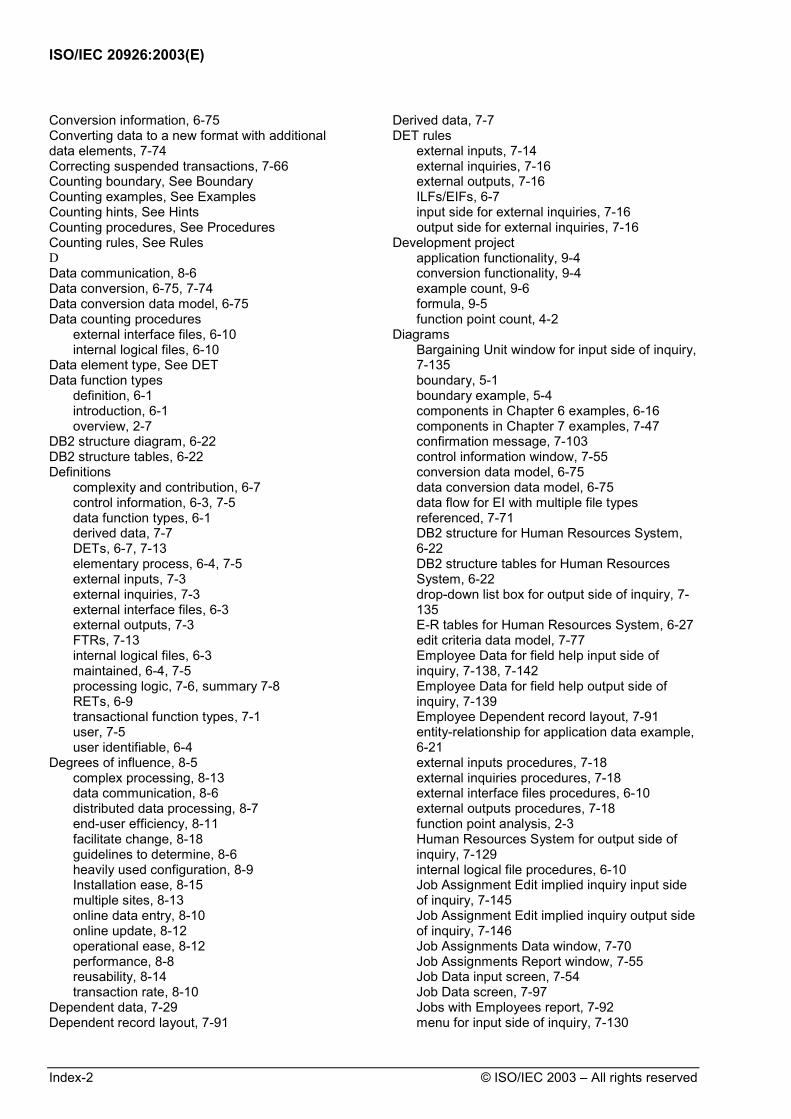
ISO/IEC 20926:2003(E)
Index-2 © ISO/IEC 2003 – All rights reserved
Conversion information, 6-75 Converting data to a new format with additional data elements, 7-74 Correcting suspended transactions, 7-66 Counting boundary, See Boundary Counting examples, See Examples Counting hints, See Hints Counting procedures, See Procedures Counting rules, See Rules D Data communication, 8-6 Data conversion, 6-75, 7-74 Data conversion data model, 6-75 Data counting procedures
external interface files, 6-10 internal logical files, 6-10
Data element type, See DET Data function types
definition, 6-1 introduction, 6-1 overview, 2-7
DB2 structure diagram, 6-22 DB2 structure tables, 6-22 Definitions
complexity and contribution, 6-7 control information, 6-3, 7-5 data function types, 6-1 derived data, 7-7 DETs, 6-7, 7-13 elementary process, 6-4, 7-5 external inputs, 7-3 external inquiries, 7-3 external interface files, 6-3 external outputs, 7-3 FTRs, 7-13 internal logical files, 6-3 maintained, 6-4, 7-5 processing logic, 7-6, summary 7-8 RETs, 6-9 transactional function types, 7-1 user, 7-5 user identifiable, 6-4
Degrees of influence, 8-5 complex processing, 8-13 data communication, 8-6 distributed data processing, 8-7 end-user efficiency, 8-11 facilitate change, 8-18 guidelines to determine, 8-6 heavily used configuration, 8-9 Installation ease, 8-15 multiple sites, 8-13 online data entry, 8-10 online update, 8-12 operational ease, 8-12 performance, 8-8 reusability, 8-14 transaction rate, 8-10
Dependent data, 7-29 Dependent record layout, 7-91
Derived data, 7-7 DET rules
external inputs, 7-14 external inquiries, 7-16 external outputs, 7-16 ILFs/EIFs, 6-7 input side for external inquiries, 7-16 output side for external inquiries, 7-16
Development project application functionality, 9-4 conversion functionality, 9-4 example count, 9-6 formula, 9-5 function point count, 4-2
Diagrams Bargaining Unit window for input side of inquiry, 7-135 boundary, 5-1 boundary example, 5-4 components in Chapter 6 examples, 6-16 components in Chapter 7 examples, 7-47 confirmation message, 7-103 control information window, 7-55 conversion data model, 6-75 data conversion data model, 6-75 data flow for EI with multiple file types referenced, 7-71 DB2 structure for Human Resources System, 6-22 DB2 structure tables for Human Resources System, 6-22 drop-down list box for output side of inquiry, 7-135 E-R tables for Human Resources System, 6-27 edit criteria data model, 7-77 Employee Data for field help input side of inquiry, 7-138, 7-142 Employee Data for field help output side of inquiry, 7-139 Employee Dependent record layout, 7-91 entity-relationship for application data example, 6-21 external inputs procedures, 7-18 external inquiries procedures, 7-18 external interface files procedures, 6-10 external outputs procedures, 7-18 function point analysis, 2-3 Human Resources System for output side of inquiry, 7-129 internal logical file procedures, 6-10 Job Assignment Edit implied inquiry input side of inquiry, 7-145 Job Assignment Edit implied inquiry output side of inquiry, 7-146 Job Assignments Data window, 7-70 Job Assignments Report window, 7-55 Job Data input screen, 7-54 Job Data screen, 7-97 Jobs with Employees report, 7-92 menu for input side of inquiry, 7-130

ISO/IEC 20926:2003(E)
© ISO/IEC 2003 – All rights reserved Index-3
menu for output side of inquiry, 7-130 migration data, 7-74 online reporting screen, 7-96 organization of Chapter 5 examples, 6-16 organization of Chapter 6 examples, 7-47 Performance Review Notification window, 7-104 procedure overview, 2-3 record layout batch with multiple/duplicate EIs, 7-62 record layout transaction input file example, 7-62 security entity-relationship, 6-27 summary example of function point analysis, 2-4 suspense files data flow diagram, 6-36 types of function point counts, 4-3 unadjusted function point count, 2-6
Difference between ILFs and EIFs, 6-3 Distributed data processing, 8-7 Documentation, 1-8
Application of Measurement Information, 1-8 Function Point Analysis Case Studies, 1-8 Glossary, 1-9 Guidelines for Software Measurement, 1-8 IFPUG, An Introduction, 1-8 Quick Reference Counting Guide, 1-8
Drop-down list box, 7-134, 7-135 Drop-down menu, 7-127 Drop-down menu for input side of inquiry, 7-130 E E-R tables, 6-27 EI with multiple file types referenced, 7-70 EIFs, see External interface files EIs, See External inputs Elementary process
EIF example, 6-4 EI example, 7-5 EQ example, 7-28 EO example, 7-28 ILF example, 6-4
Employee Data field help, 7-138, 7-139, 7-142 Employee dependent record layout, 7-100 Employee Setup window, 7-108 End-user efficiency, 8-11 Enhancement project
application functionality, 9-11 conversion functionality, 9-11 example count, 9-13 formula, 9-12 function point count, 4-2 value adjustment factor, 9-11
EOs, See External outputs EQs, See External inquiries Error/confirmation messages, 7-103 Estimated count, 4-3 Examples
alternate index, 6-42 application count, 9-19 application data, 6-42
application menus, 7-127 audit data for inquiries and reports, 6-34 batch with multiple and duplicate EIs, 7-62 complexity and contribution for EIFs, 6-65 complexity and contribution for ILFs, 6-43 confirmation messages, 7-103 control information, 6-3, 7-54 control information for EIs, 7-55 control information for external inputs, 7-5 conversion information, 6-75 converting data to a new format, 7-74 correcting suspended transactions, 7-66 data conversion, 6-75 data flow diagram to count referenced to multiple files, 7-71 derived data, 7-26 development project count, 9-6 drop-down list box, 7-134 EI with multiple file types referenced, 7-70 elementary process for EIs, 7-29 elementary process for EOs, 7-37 elementary process for EQs, 7-34 elementary process for ILFs/EIFs, 6-4 enhancement project count, 9-13 error/confirmation messages, 7-103 external inputs, 7-53 external inquiries counting, 7-126 external interface files, 6-60 external outputs, 7-90 field help first count, 7-138 field help second occurrence, 7-142 field-level help, 6-69 hard copy report, 7-92 Help application, 6-69 ILF counting, 6-19 ILF/EIF mandatory subgroups for RETs, 6-9 ILF/EIF optional subgroups for RETs, 6-9 implied data retrieval, 7-145 implied inquiry, 7-129 list of retrieved data, 7-110 maintained for EIs, 7-5 maintained for ILFs/EIFs, 6-4 merging groups of data, 6-21 navigational aids, 7-127 navigational menus, 7-127 notification message, 7-104 online add transaction, 7-58 online reporting, 7-96 processing logic for external inquiries, 7-6, 7-8 processing logic for external outputs, 7-6, 7-8 providing data to other applications, 6-67 references to multiple files, 7-70 referencing data from another application, 6-64, 7-77 referencing data from other applications, 6-61 report definition, 6-42 report output, 7-92, 7-96 screen access security, 6-26 screen input, 7-58 security, 6-26

ISO/IEC 20926:2003(E)
Index-4 © ISO/IEC 2003 – All rights reserved
summary descriptions of external inputs examples, 7-53 summary descriptions of external inquiry examples, 7-126 summary descriptions of external output examples, 7-90 summary of EIFs and RETs/DETs counted, 6-84 summary of EIs and FTRs/DETs counted, 7-86 summary of EOs and FTRs/DETs counted, 7-120 summary of EQs and FTRs/DETs counted, 7-154 summary of ILFs and RETs/DETs counted, 6-55 suspended file, 7-66 suspended jobs, 6-35 transaction input file, 6-62 transaction sent to another application, 7-100, 7-151 transaction with formatted record types, 7-62 transaction with multiple types, 7-62 user access security, 6-26 user identifiable for ILFs/EIFs, 6-4 user-defined report definitions, 6-39 window access audit data, 6-34 window help, 6-69 within chapters, 1-3
External inputs batch with multiple and duplicate EIs, 7-62 complexity and contribution procedures, 7-21 complexity and contribution rules, 7-14 complexity matrix, 7-21, 7-87 control information, 7-5, 7-54 control information counting rules, 7-11 correcting suspended transactions, 7-66 data conversion example, 7-74 definition, 7-3 DET definition, 7-13 DET rules, 7-14 EI with multiple file types referenced, 7-70 example control information, 7-5, 7-54 example elementary process, 7-5 examples, 7-62 FTR definition, 7-13 FTR rules, 7-14 hints to help with counting, 7-24 identification procedures, 7-19 identification rules, 7-11, 7-51 introduction, 7-3 maintained example, 7-5 procedure diagram, 7-18 screen input example, 7-58 summary of example EIs and FTRs/DETs counted, 7-86 suspended transactions, 7-66 translation table, 7-6, 7-8
External inquiries application menus example, 7-127
complexity and contribution counting procedures, 7-22 complexity and contribution rules, 7-16 complexity matrix, 7-22, 7-155 counting examples, 7-124 counting procedures, 7-18 definition, 7-3 derived data, 7-7 DET rules, 7-16 drop-down list box, 7-134 example elementary process, 7-5 example processing logic, 7-6 field-level help first count, 7-138 field-level help second occurrence, 7-142 FTR rules, 7-16 hints to help with counting, 7-24 identification rules, 7-12, 7-125 implied inquiry, 7-145 list of retrieved data, 7-129 procedure diagram, 7-15 summary of example EQs and FTRs/DETs counted, 7-154 translation table, 7-6, 7-8
External interface files complexity and contribution procedures, 6-11 complexity and contribution rules, 6-7 conversion information, 6-65 data conversion example, 6-60 data referenced in other applications, 6-47 definition, 6-3 DET rules, 6-7 difference from ILFs, 6-3 example control information, 6-3 example elementary process, 6-4 examples, 6-60 field-level help, 6-70 Help application example, 6-60 hints to help with counting, 6-13 identification procedures, 6-10 identification rules, 6-6 maintain example, 6-4 mandatory subgroups for RETs, 6-9 optional subgroups for RETs, 6-9 procedure diagram, 6-10 procedures, 6-10 providing data to other applications, 6-59, 6-67 referencing data from another application for EIs, 7-77 referencing data from another application, 6-61 referencing data from other applications, 6-64 RET rules, 6-9 summary of example ILFs and RETs/DETs counted, 6-55 transaction input file, 6-77 translation table, 6-11 user identifiable example, 6-4 window help, 6-70
External outputs complexity and contribution procedures, 7-22 complexity and contribution rules, 7-16

ISO/IEC 20926:2003(E)
© ISO/IEC 2003 – All rights reserved Index-5
complexity matrix, 7-22 definition, 7-3 DET rules, 7-16 error/confirmation messages example, 7-103 example elementary process, 7-5 example processing logic, 7-6 examples, 7-90 FTR rules, 7-16 hints to help with counting, 7-24 identification procedures, 7-19 identification rules, 7-18 notification message, 7-104 online reporting, 7-96 procedure diagram, 7-19 report output example, 7-92 summary of example EOs and FTRs/DETs counted, 7-120 transaction sent to another application, 7-100 translation table, 7-23
F Facilitate change, 8-18 Field-level help, 6-55 Field-level help first occurrence, 7-138 Field-level help second occurrence, 7-142 File, 6-1 Adjusted function point count
application, 9-16 development project, 9-6 enhancement project, 9-11 final calculations, 9-10, 9-16 overview, 9-1
Final counts, 4-3, 9-1 Formatted record types, 7-62 Formulas
application, 9-17 conversion functionality, 9-4, 9-11 development project, 9-5 enhancement project, 9-12 establish initial count, 9-17 function point analysis, 9-3 reflect enhancements, 9-17
FTR rules external inputs, 7-14 external inquiries, 7-17 external outputs, 7-16
Function point analysis application, 4-2 application calculations, 9-17 calculations, 9-3 conversion functionality, 9-4, 9-11 development project, 4-2 development project calculations, 9-4 enhancement project, 4-2 enhancement project calculations, 9-11 formula for development project application functionality, 9-5 formula for enhancement project application functionality, 9-12 formulas, 9-3 formulas for application count, 9-17
formulas for development project, 9-5 formulas for enhancement project, 9-12 objectives, 2-2 overview, 2-1 procedures, 2-3 procedures by chapter, 2-3 review of procedures, 9-3 summary diagram, 2-4 summary example, 2-4
Function point count, see Function point analysis Function point counting procedures, 2-3 Function types
data, 6-1 external inputs, 7-19 external inquiries, 7-19 transactional, 7-19
G General system characteristics, 8-4
degrees of influence, 8-5 graphical user interface
Bargaining Unit window, 7-134 drop-down list box, 7-134 Employee Setup window, 7-128 field help, 6-55, 7-121, 7-122, 7-127, 7-128
field-level help first occurrence, 7-138 field-level help second occurrence, 7-142
Human Resources System window, 7-127, 7-130 implied inquiry, 7-145 Job Assignment Edit window, 7-145, 7-146 Job Assignments Data window, 7-70
menus counting example, 7-127 Performance Review Notification window, 7- 104 window access audit data, 6-33 window help, 6-69 GUI, See graphical user interface Guidelines 1-2 Guidelines to determine degrees of influence, 8-6 H Hard copy report, 7-92 Heavily used configuration, 8-9 Help application, 6-69 Hints
boundary, 5-6 counting EIFs, 6-13 counting EIs, 7-24 counting EOs, 7-24, 7-26 counting EQs, 7-24, 7-26 counting ILFs, 6-13
Human Resources System window, 7-127 I IBM CIS & A Guidelines, 1-2 Identification procedures
external interface files, 6-10 external outputs, 7-19 ILF/EIFs, 6-10
Identification rules external inputs, 7-19 external inquiries, 7-19
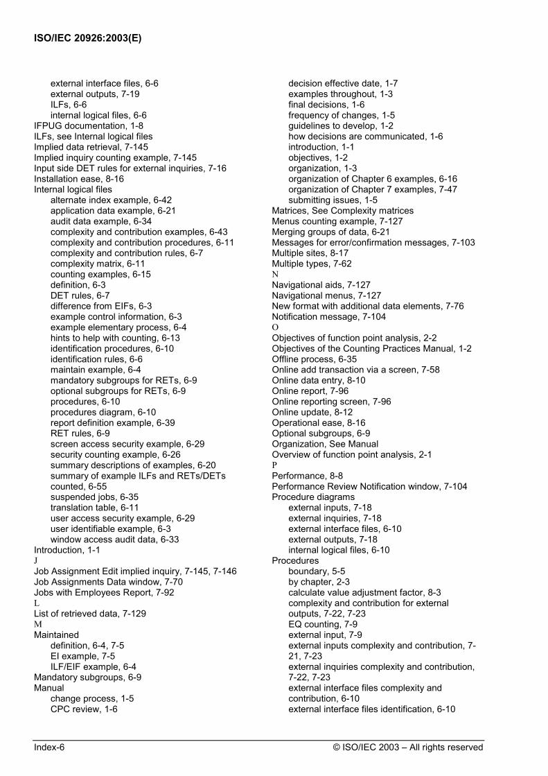
ISO/IEC 20926:2003(E)
Index-6 © ISO/IEC 2003 – All rights reserved
external interface files, 6-6 external outputs, 7-19 ILFs, 6-6 internal logical files, 6-6
IFPUG documentation, 1-8 ILFs, see Internal logical files Implied data retrieval, 7-145 Implied inquiry counting example, 7-145 Input side DET rules for external inquiries, 7-16 Installation ease, 8-16 Internal logical files
alternate index example, 6-42 application data example, 6-21 audit data example, 6-34 complexity and contribution examples, 6-43 complexity and contribution procedures, 6-11 complexity and contribution rules, 6-7 complexity matrix, 6-11 counting examples, 6-15 definition, 6-3 DET rules, 6-7 difference from EIFs, 6-3 example control information, 6-3 example elementary process, 6-4 hints to help with counting, 6-13 identification procedures, 6-10 identification rules, 6-6 maintain example, 6-4 mandatory subgroups for RETs, 6-9 optional subgroups for RETs, 6-9 procedures, 6-10 procedures diagram, 6-10 report definition example, 6-39 RET rules, 6-9 screen access security example, 6-29 security counting example, 6-26 summary descriptions of examples, 6-20 summary of example ILFs and RETs/DETs counted, 6-55 suspended jobs, 6-35 translation table, 6-11 user access security example, 6-29 user identifiable example, 6-3 window access audit data, 6-33
Introduction, 1-1 J Job Assignment Edit implied inquiry, 7-145, 7-146 Job Assignments Data window, 7-70 Jobs with Employees Report, 7-92 L List of retrieved data, 7-129 M Maintained
definition, 6-4, 7-5 EI example, 7-5 ILF/EIF example, 6-4
Mandatory subgroups, 6-9 Manual
change process, 1-5 CPC review, 1-6
decision effective date, 1-7 examples throughout, 1-3 final decisions, 1-6 frequency of changes, 1-5 guidelines to develop, 1-2 how decisions are communicated, 1-6 introduction, 1-1 objectives, 1-2 organization, 1-3 organization of Chapter 6 examples, 6-16 organization of Chapter 7 examples, 7-47 submitting issues, 1-5
Matrices, See Complexity matrices Menus counting example, 7-127 Merging groups of data, 6-21 Messages for error/confirmation messages, 7-103 Multiple sites, 8-17 Multiple types, 7-62 N Navigational aids, 7-127 Navigational menus, 7-127 New format with additional data elements, 7-76 Notification message, 7-104 O Objectives of function point analysis, 2-2 Objectives of the Counting Practices Manual, 1-2 Offline process, 6-35 Online add transaction via a screen, 7-58 Online data entry, 8-10 Online report, 7-96 Online reporting screen, 7-96 Online update, 8-12 Operational ease, 8-16 Optional subgroups, 6-9 Organization, See Manual Overview of function point analysis, 2-1 P Performance, 8-8 Performance Review Notification window, 7-104 Procedure diagrams
external inputs, 7-18 external inquiries, 7-18 external interface files, 6-10 external outputs, 7-18 internal logical files, 6-10
Procedures boundary, 5-5 by chapter, 2-3 calculate value adjustment factor, 8-3 complexity and contribution for external outputs, 7-22, 7-23 EQ counting, 7-9 external input, 7-9 external inputs complexity and contribution, 7-21, 7-23 external inquiries complexity and contribution, 7-22, 7-23 external interface files complexity and contribution, 6-10 external interface files identification, 6-10

ISO/IEC 20926:2003(E)
© ISO/IEC 2003 – All rights reserved Index-7
external outputs identification, 7-9 function point analysis, 2-3, 9-3 function point counting, 2-3 ILF/EIF counting, 6-10 internal logical files complexity and contribution, 6-10 internal logical files identification, 6-10 overview diagram, 2-3 steps, 2-3
Processing logic external input, 7-6, 7-8 external inquiry, 7-6, 7-8 external outputs, 7-6, 7-8
Providing data to other applications, 6-67 R Record element type, See RET Record layout for input file transaction, 6-77 Record types, 7-63 Referenced to multiple files, 7-70 Referencing data from another application, 6-64, 7-77 Referencing data from other applications, 6-61 Report definition example, 6-39 Report output example, 7-92 Reports
hard copy, 7-92 online, 7-96
RET rules ILFs/EIFs, 6-9 mandatory subgroups for ILFs/EIFs, 6-9 optional subgroups for ILFs/EIFs, 6-9
Reusability, 8-14 Review of function point analysis steps, 9-3 Rules
boundary, 5-5 complexity and contribution for EQs, 7-16 complexity and contribution for external inputs, 7-14 complexity and contribution for external outputs, 7-16 complexity and contribution for ILFs/EIFs, 6-7 control information, 7-5 DETs for external inputs, 7-14 DETs for external inquiries, 7-16 DETs for external outputs, 7-16 DETs for ILFs/EIFs, 6-7 EIF identification, 6-6 external inputs identification, 7-9, 7-18 external inquiries identification, 7-9, 7-18 external outputs identification, 7-9, 7-18 FTRs for external inputs, 7-14 FTRs for external inquiries, 7-16 FTRs for external outputs, 7-16 ILF identification, 6-6 ILF/EIF, 6-5 ILF/EIF mandatory subgroups, 6-9 ILF/EIF optional subgroups, 6-9 input side for DET external inquiries, 7-16 internal logical files, 6-3 output side for DET external inquiries, 7-16
RETs for ILFs/EIFs, 6-9 transactional types, 7-1
S Scope creep, 4-3 Screen access security, 6-29 Screen input, 7-58 Screens
confirmation message, 7-103 Employees by Assignment Duration, 7-88
error/confirmation messages, 7-103 online reporting, 7-96
Security example, 6-26 Security entity-relationship diagram, 6-27 Security example, 6-26 Submitting issues, 1-5 Summary counting diagram, 2-4 Summary counting example, 2-4 Summary description of external input examples, 7-45 Summary description of external outputs examples, 7-89 Summary descriptions of external inquiries examples, 7-124 Summary descriptions of ILF examples, 6-20 Summary of EIFs and RETs/DETs counted, 6-84 Summary of EIs and FTRs/DETs for examples, 7-87 Summary of EOs and FTRs/DETs counted, 7-120 Summary of EQs and FTRs/DETs counted for examples, 7-154 Summary of ILFs and RETs/DETs counted, 6-55 Suspended transaction file, 7-68 Suspended jobs, 6-35 Suspense files data flow diagram, 6-35 T Transaction input file, 6-77 Transaction rate, 8-10 Transaction sent to another application, 7-100 Transaction with formatted record types, 7-62 Transaction with multiple types, 7-62 Transactional function types
definition, 7-1 introduction, 7-1 overview, 2-8
Translation tables external inputs, 7-23 external inquiries, 7-23 external outputs, 7-23 ILFs/EIFs, 6-11
Type of count application, 4-2 definitions, 4-2 development project, 4-2 diagram, 4-3 enhancement project, 4-2 estimated and final counts, 4-3 overview, 2-5
U Unadjusted function point count
data function types, 6-1

ISO/IEC 20926:2003(E)
Index-8 © ISO/IEC 2003 – All rights reserved
overview, 2-6 transactional function types, 7-1
User access security example, 6-26 User identifiable
definition, 6-4 ILF/EIF example, 6-4
User-defined report definitions, 6-39 V Value adjustment factor, 8-1
calculation, 8-3 degrees of influence, 8-5 overview, 2-9
W Window access audit data, 6-34 Window help, 6-69 Windows
Bargaining Unit, 7-116 drop-down list box, 7-134 Employee Setup, 7-108 field help, 7-121, 7-122, 7-127, 7-13, 7-142 Human Resources System, 7-128, 7-130 implied inquiry, 7-145, 7-146 Job Assignment Edit, 7-146 Job Assignments Data, 7-59, 7-96 Performance Review Notification, 7-104
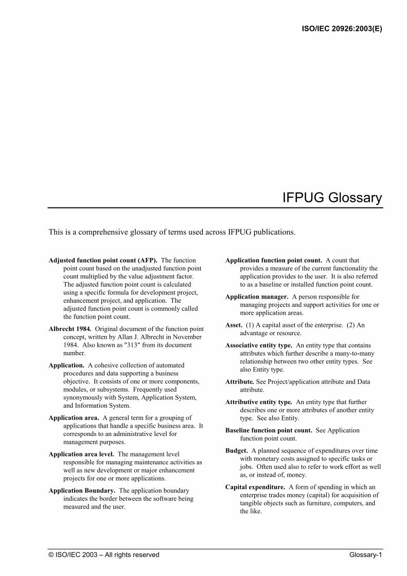
ISO/IEC 20926:2003(E)
© ISO/IEC 2003 – All rights reserved Glossary-1
IFPUG Glossary This is a comprehensive glossary of terms used across IFPUG publications.
Adjusted function point count (AFP). The function
point count based on the unadjusted function point count multiplied by the value adjustment factor. The adjusted function point count is calculated using a specific formula for development project, enhancement project, and application. The adjusted function point count is commonly called the function point count.
Albrecht 1984. Original document of the function point concept, written by Allan J. Albrecht in November 1984. Also known as "313" from its document number.
Application. A cohesive collection of automated procedures and data supporting a business objective. It consists of one or more components, modules, or subsystems. Frequently used synonymously with System, Application System, and Information System.
Application area. A general term for a grouping of applications that handle a specific business area. It corresponds to an administrative level for management purposes.
Application area level. The management level responsible for managing maintenance activities as well as new development or major enhancement projects for one or more applications.
Application Boundary. The application boundary indicates the border between the software being measured and the user.
Application function point count. A count that provides a measure of the current functionality the application provides to the user. It is also referred to as a baseline or installed function point count.
Application manager. A person responsible for managing projects and support activities for one or more application areas.
Asset. (1) A capital asset of the enterprise. (2) An advantage or resource.
Associative entity type. An entity type that contains attributes which further describe a many-to-many relationship between two other entity types. See also Entity type.
Attribute. See Project/application attribute and Data attribute.
Attributive entity type. An entity type that further describes one or more attributes of another entity type. See also Entity.
Baseline function point count. See Application function point count.
Budget. A planned sequence of expenditures over time with monetary costs assigned to specific tasks or jobs. Often used also to refer to work effort as well as, or instead of, money.
Capital expenditure. A form of spending in which an enterprise trades money (capital) for acquisition of tangible objects such as furniture, computers, and the like.

ISO/IEC 20926:2003(E)
Glossary-2 © ISO/IEC 2003 – All rights reserved
Complex processing GSC. One of the 14 general system characteristics describing the degree to which processing logic influences the development of the application.
Contribution. The function type's (ILF, EIF, EI, EO, EQ) contribution to the unadjusted function point count.
Control information. Control Information is data that influences an elementary process of the application being counted. It specifies what, when, or how data is to be processed.
Conversion. Those activities associated with mapping data or programs from one format to another, for example, converting an application from COBOL to VS COBOL II. The assumption is that functionality remains the same.
Conversion functionality. For a development project, functions provided to convert data and/or provide other user-specified conversion requirements, such as special conversion reports. For an enhancement project, functions delivered because of any conversion functionality required by the user.
Corporate executive level. The management level responsible for the enterprise, including the Board of Directors.
Counting Practices Committee (CPC). The working committee that maintains the IFPUG Counting Practices Manual.
Counting Scope. The counting scope defines the functionality which will be included in a particular function point count.
Data attribute. A characteristic of an entity. Data attributes are generally analogous to data element types (DETs).
Data communications GSC. One of the 14 general system characteristics describing the degree to which the application communicates directly with the processor.
Data element type (DET). A data element type is a unique user recognizable, non-repeated field.
Data functions. The functionality provided to the user to meet internal and external data requirements. Data functions are either internal logical files (ILFs) or external interface files (EIFs).
Defect. A problem which, if not corrected, could cause an application to either fail or to produce incorrect results. The absence of functionality that was specified or required is also considered a defect.
Defect removal. See Repair.
Degree of influence (DI). A numerical indicator of the amount of impact of each of the 14 general system characteristics, ranging from zero to five. These indicators are used to compute the value adjustment factor.
Delivery rate. The productivity measure for creating or enhancing an application. It is expressed by the Project Function Points divided by the Work Effort for the development or enhancement project.
Derived data. Data that requires processing other than or in addition to direct retrieval and validation of information from internal logical files and/or external interface files.
Development. The specification, construction, testing, and delivery of a new information system.
Development project function point count (DFP). A count that measures the functions provided to the users with the first installation of the software delivered when the project is complete.
Distributed data processing GSC. One of the 14 general system characteristics describing the degree to which the application transfers data among components of the application.
Effectiveness. Producing the intended or desired result.
Efficiency. Producing a result with a minimum of extraneous or redundant effort.
Elementary process. An elementary process is the smallest unit of activity that is meaningful to the user(s).
End-user efficiency GSC. One of the 14 general system characteristics describing the degree of consideration for human factors and ease of use for the user of the application measured.
Enhancement. The modification of an existing application.
Enhancement project function point count (EFP). A count that measures the modifications to the existing application that add, change, or delete user functions delivered when the project is complete.
Entity (or entity type). A fundamental thing of relevance to the user, about which a collection of facts is kept. An association between entities that contains attributes is itself an entity.
Entity subtype. A subdivision of an entity type. A subtype inherits all the attributes and relationships of its parent entity type, and may have additional, unique attributes and relationships. See also Entity type.

ISO/IEC 20926:2003(E)
© ISO/IEC 2003 – All rights reserved Glossary-3
External input (EI). An external input (EI) is an elementary process that processes data or control information that comes from outside the application’s boundary. The primary intent of an EI is to maintain one or more ILFs and/or to alter the behavior of the system. See also External inquiry and External output.
External inquiry (EQ). An external inquiry (EQ) is an elementary process that sends data or control information outside the application boundary. The primary intent of an external inquiry is to present information to a user through the retrieval of data or control information from an ILF or EIF. The processing logic contains no mathematical formulas or calculations, and creates no derived data. No ILF is maintained during the processing, nor is the behavior of the system altered. See also External input and External output.
External interface file (EIF). An external interface file (EIF) is a user identifiable group of logically related data or control information referenced by the application, but maintained within the boundary of another application. The primary intent of an EIF is to hold data referenced through one or more elementary processes within the boundary of the application counted. This means an EIF counted for an application must be in an ILF in another application. See also Internal logical file.
External output (EO). An external output (EO) is an elementary process that sends data or control information outside the application’s boundary. The primary intent of an external output is to present information to a user through processing logic other than, or in addition to, the retrieval of data or control information. The processing logic must contain at least one mathematical formula or calculation, or create derived data. An external output may also maintain one or more ILFs and/or alter the behavior of the system. See also External input and External inquiry.
Facilitate change GSC. One of the 14 general system characteristics describing the degree to which the application has been developed for easy modification of processing logic or data structure.
File. For data functions, a logically related group of data, not the physical implementation of those groups of data.
File type referenced (FTR). A file type referenced is
• An internal logical file read or maintained by a transactional function or
• An external interface file read by a transactional function
First normal form. Result of a normalization process that transforms groups of data so they have a unique identifier, one or more attributes, and no repeating attributes.
Foreign key. Data in an ILF or EIF that exists because the user requires a relationship with another ILF or EIF.
Function. The features or capabilities of an application as seen by the user.
Functionality. See Function.
Function point (FP). A measure which represents the functional size of application software.
Function point analysis. A standard method for measuring software development and maintenance from the customer's point of view.
Function point count. The function point measurement of a particular application or project.
Function type. The five basic information services provided to the user of an application and identified in function point analysis. The five function types are external input, external output, external inquiry, internal logical file, and external interface file.
Functional complexity. A specific function type's complexity rating which has a value of low, average, or high. For data function types, the complexity is determined by the number of RETs and DETs. For transactional function types, the complexity is determined by the number of FTRs and DETs.
General system characteristics (GSCs). The general system characteristics are a set of 14 questions that evaluate the overall complexity of the application.
Heavily used configuration GSC. One of the 14 general system characteristics describing the degree to which computer resource restrictions influenced the development of the application.
IBM CIS & A Guideline 313. See Albrecht 1984.
IFPUG. The International Function Point Users Group is a membership governed, non-profit organization committed to promoting and supporting function point analysis and other software measurement techniques.
Installation ease GSC. One of the 14 general system characteristics describing the degree to which conversion from previous environments influenced the development of the application.
Installed function point count. See Application function point count.
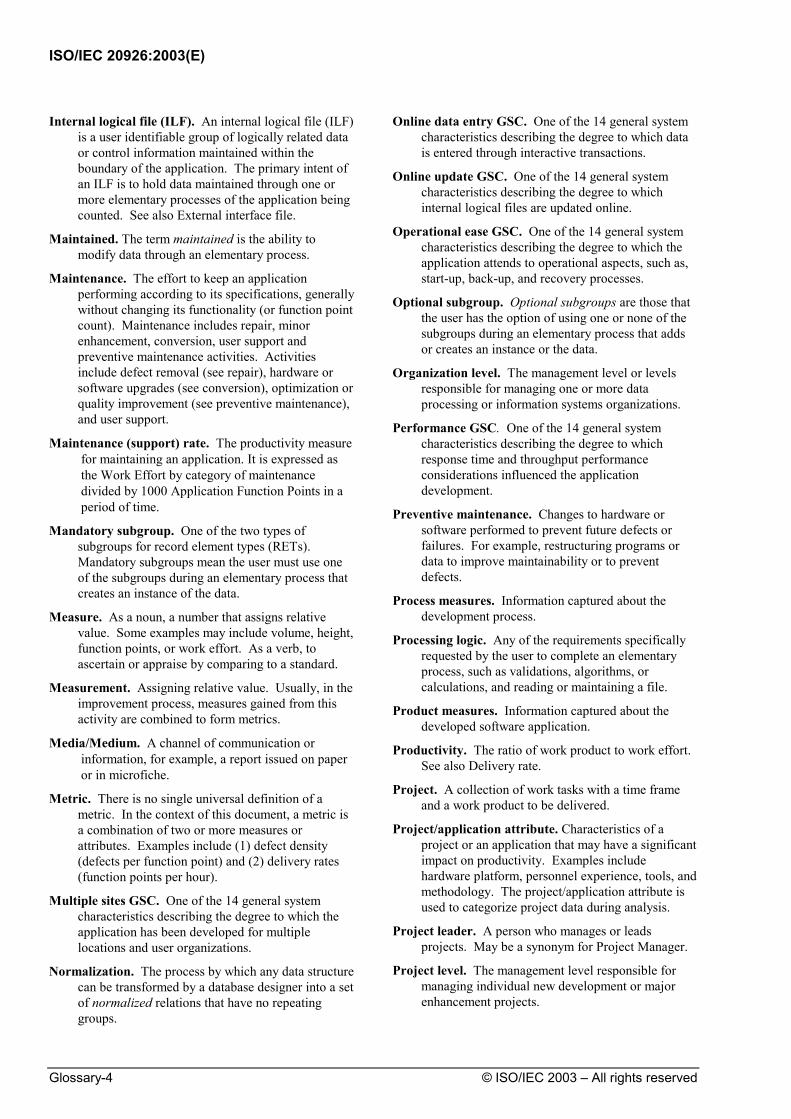
ISO/IEC 20926:2003(E)
Glossary-4 © ISO/IEC 2003 – All rights reserved
Internal logical file (ILF). An internal logical file (ILF) is a user identifiable group of logically related data or control information maintained within the boundary of the application. The primary intent of an ILF is to hold data maintained through one or more elementary processes of the application being counted. See also External interface file.
Maintained. The term maintained is the ability to modify data through an elementary process.
Maintenance. The effort to keep an application performing according to its specifications, generally without changing its functionality (or function point count). Maintenance includes repair, minor enhancement, conversion, user support and preventive maintenance activities. Activities include defect removal (see repair), hardware or software upgrades (see conversion), optimization or quality improvement (see preventive maintenance), and user support.
Maintenance (support) rate. The productivity measure for maintaining an application. It is expressed as the Work Effort by category of maintenance divided by 1000 Application Function Points in a period of time.
Mandatory subgroup. One of the two types of subgroups for record element types (RETs). Mandatory subgroups mean the user must use one of the subgroups during an elementary process that creates an instance of the data.
Measure. As a noun, a number that assigns relative value. Some examples may include volume, height, function points, or work effort. As a verb, to ascertain or appraise by comparing to a standard.
Measurement. Assigning relative value. Usually, in the improvement process, measures gained from this activity are combined to form metrics.
Media/Medium. A channel of communication or information, for example, a report issued on paper or in microfiche.
Metric. There is no single universal definition of a metric. In the context of this document, a metric is a combination of two or more measures or attributes. Examples include (1) defect density (defects per function point) and (2) delivery rates (function points per hour).
Multiple sites GSC. One of the 14 general system characteristics describing the degree to which the application has been developed for multiple locations and user organizations.
Normalization. The process by which any data structure can be transformed by a database designer into a set of normalized relations that have no repeating groups.
Online data entry GSC. One of the 14 general system characteristics describing the degree to which data is entered through interactive transactions.
Online update GSC. One of the 14 general system characteristics describing the degree to which internal logical files are updated online.
Operational ease GSC. One of the 14 general system characteristics describing the degree to which the application attends to operational aspects, such as, start-up, back-up, and recovery processes.
Optional subgroup. Optional subgroups are those that the user has the option of using one or none of the subgroups during an elementary process that adds or creates an instance or the data.
Organization level. The management level or levels responsible for managing one or more data processing or information systems organizations.
Performance GSC. One of the 14 general system characteristics describing the degree to which response time and throughput performance considerations influenced the application development.
Preventive maintenance. Changes to hardware or software performed to prevent future defects or failures. For example, restructuring programs or data to improve maintainability or to prevent defects.
Process measures. Information captured about the development process.
Processing logic. Any of the requirements specifically requested by the user to complete an elementary process, such as validations, algorithms, or calculations, and reading or maintaining a file.
Product measures. Information captured about the developed software application.
Productivity. The ratio of work product to work effort. See also Delivery rate.
Project. A collection of work tasks with a time frame and a work product to be delivered.
Project/application attribute. Characteristics of a project or an application that may have a significant impact on productivity. Examples include hardware platform, personnel experience, tools, and methodology. The project/application attribute is used to categorize project data during analysis.
Project leader. A person who manages or leads projects. May be a synonym for Project Manager.
Project level. The management level responsible for managing individual new development or major enhancement projects.

ISO/IEC 20926:2003(E)
© ISO/IEC 2003 – All rights reserved Glossary-5
Project manager. A person who manages one or more projects or groups of projects.
Purpose of the Count. The purpose of a function point count is to provide an answer to a business problem.
Quality. Quality includes: conformity to user expectations, conformity to user requirements, customer satisfaction, reliability, and level of defects present. Context and policy will decide the best definition for a given situation.
Ratio. In the context of this document, ratio is defined as the result of dividing one measured quantity by another.
Record element type (RET) A record element type (RET) is a user recognizable subgroup of data elements within an ILF or EIF.
RECUP. Acronym for Repair/Enhancement/ Conversion/User support/Prevention. See also Maintenance (support) rate.
Relationship. An association of interest between two entities. A relationship does not have attributes and does not count as a RET when counting function points.
Release. A delivered version of an application which may include all or part of an application.
Repair. The correction of defects that have resulted from errors in external design, internal design, or code. Examples are missing functions that do not result in application failure (external design error) or errors resulting in a stop-run situation (code error).
Reusability GSC. One of the 14 general system characteristics describing the degree to which the application and the code in the application have been specifically designed, developed, and supported to be usable in other applications
Scope creep/gallop. Additional functionality that was not specified in the original requirements, but is identified as the scope is being clarified and the functions defined.
Second normal form. Result of a normalization process that transforms groups of data so that each non-key attribute depends on the key attribute(s) of the group of data and all parts of the key attribute(s).
Software Engineering Institute (SEI) Maturity. The ability of an organization to achieve a controlled and measured process as the foundation for continued improvement (Humphrey). The level of experience of an organization or project with a particular tool, resource, technique, or methodology.
Subtypes. See Entity subtypes.
Support. See Maintenance.
System. See Application.
Third normal form. Result of a normalization process that transforms groups of data so that each non-key attribute does not depend on any other non-key attribute.
Total degree of influence (TDI). The sum of the degrees of influence for the fourteen GSCs.
Transaction rate GSC. One of the 14 general system characteristics describing the degree to which the rate of business transactions influenced the development of the application.
Transactional functions. The functionality provided to the user to process data by an application. Transactional functions are defined as external inputs, external outputs, and external inquiries.
Trend. A time analysis showing repeated occurrences of a particular measure or metric.
Unadjusted function point count (UFP). The measure of the functionality provided to the user by the project or application. It is contributed by the measure of two function types—data and transactional.
User. A user is any person that specifies Functional User Requirements and/or any person or thing that communicates or interacts with the software at any time.
User identifiable. The term user identifiable refers to defined requirements for processes and/or groups of data that are agreed upon, and understood by, both the user(s) and software developer(s).
User view. A user view represents a formal description of the user’s business needs in the user’s language. Developers translate the user information into information technology language in order to provide a solution.
Value adjustment factor (VAF). The factor that indicates the general functionality provided to the user of the application. The VAF is calculated based on an assessment of the 14 general system characteristics (GSCs) for an application.
Work effort. Labor resources required for the production of a specified output. Here referring to the effort required to develop or maintain an application. Labor resources are usually expressed as work hours.
Work product. The product that is created by information systems work, here the result of a software development effort.
313. See Albrecht 1984.

ISO/IEC 20926:2003(E)
ICS 35.080 Price based on 338 pages
© ISO 2003 – All rights reserved