
Issues Related to the Selection of U.S. Navy Buildings for ... This report describes research...
91
AD-A206 077 I) CR 89.006 January 1989 Investigation Conducted by University of California, Los Angeles m Sponsored by Naval Facilities Contract Report Engineering Command Issues Related to the Selection of U.S. Navy Buildings for Base Isolation ABSTRACT This report presents research con- ducted at UCLA. It recommends the base isolation systems that are fully satisfactory for Navy buildings. The report contains a discus- sion of the building selection process, quality control and design issues. A technical discussion of ground motion, torsion and uncertainty is also presented. DTIC ." LECTE ~ MAR2 7 9 Sclb Dap D NAVAL CIVIL ENGINEERING LABOR,-r,,,.,,Y PORT HUENEME CALIFORNIA 93043 Approved for public release; distibutionpnil) d. o 4 ( 1 " - ,, . k } .L "
Transcript of Issues Related to the Selection of U.S. Navy Buildings for ... This report describes research...

AD-A206 077 I)CR 89.006January 1989
Investigation Conducted by
University of California, Los Angelesm Sponsored by Naval Facilities
Contract Report Engineering Command
Issues Related to the Selectionof U.S. Navy Buildings
for Base Isolation
ABSTRACT This report presents research con-ducted at UCLA. It recommends the baseisolation systems that are fully satisfactory forNavy buildings. The report contains a discus-sion of the building selection process, qualitycontrol and design issues. A technicaldiscussion of ground motion, torsion anduncertainty is also presented.
DTIC." LECTE ~
MAR2 7 9
Sclb DapD
NAVAL CIVIL ENGINEERING LABOR,-r,,,.,,Y PORT HUENEME CALIFORNIA 93043
Approved for public release; distibutionpnil) d. o 4 ( 1 " -
,, . k } .L "

.5i INI :e
E UOI
A c
qvC) C4I n C U * -'EL 6 - 6 Ceg c
cc j
NN
E LL
01111 Lim'1 I., J.jo
; 9 8' 7 854 3 12 1 ildmf
~~ mac... E EE. .. a m
VC4
o o C 0 6 U- ian 6d v 6J1 >
S N~.- ~1DO NO W~fl~~q YO
LL
I 2v0 ) 5

UnclassifiedSECURITY CL ,ASSIFICATIN OrF T S PA([ 'bh-, [1.,. F,-. )
kHA ) tN'rkt<rf( 1lREPORT DOCUMENTATION PAGE F , INIrI I 1%.F(,t REPORT NUMHFR 2 UOVT ACCESSION NO 3 RFCIPtENTS- A A, MR( PEW
CR 89.006 _4 TITLE 111dS,U,t-1 S T Pk CF RFPnRT '. PF RF -" .1-I
Issues Related to the Selection of FinalOct 1987 - Jan 1989U.S. Navy Buildings for Base Isolation Pc.ro . .. E- ... -P
7 AUTHOR, . 8 CONTRA -T ')R CRA% N-(JER.,
Gary C. Hart, Professor IPA Contract Agreement
9 PERFORMING ORGANIZATON NAME ANO AITIESS 'D PFOIC A.P E. F f P 7IF ,'U ARE A A .1: . "1 ,1 E PSDepartment of Civil Engineering YM33F60-001-0-06-010University of California, Los Angeles
II CONTROLLING OFFICE NAME. AND AD.DRESS I2 P T DATE
Naval Civil Engineering Laboratory January 1989Port Hueneme, CA 93043-5003 . .
I MC'NITORING AGENCY NAME & AOORESG, 41,ft ,,l IL,,,, .,,n I)l, SECGPI Y A 1 ASS-1'
Naval Facilities Engineering Command Unclassified20C Stovall Street I. 5FCLASS,' .&,, AT . ,, .,
Alexandria, VA 22332-2300-- I-P1i81 TIC)N STATEMENT :,,T fh- Hep,
Approved for public release; distribution is unlimited.
1 I DISTFIBUTION STATEMENT 1,1 AC SSPta! n1.,Cd ,- R1, 2b', -I -1-It7e7r tT N~port'
1A SUPPLEMENTARY NOTES
19 KEY WOROS tonlnue n fevS ,If IT.n, I, C-11f1d- -t. I S - It
j seismic design, base isolation, structural response
20 ABSTRACT r(onUA,,C ,,C ,.CTr dC ,, I Ct ..R '
ad -dC,6r" ) bock ATTmbCTI
This report presents research conducted at UCLA. It recommendsthe base isolation systems that are fully satisfactory forNavy buildings. The report contains a discussion of thebuilding selection process, quality control and design issues.A technical discussion of ground motion, torsion and uncer-tainty is also presented.
F OPM
DD JAN 73 1473 EITION OSr UnclassiNfVied _____-_
SECURITY CLASSIFICATION IF THIS PA,;E *71- V-. f
; m~l enui l l I H I Ill I N II'

FORWORD
This report describes research performed for the U.S. Navy, Naval Civil EngineeringLaboratory, Port Hueneme, under the Seismic Hazard Mitigation Program (YM33F60001) .The research was performed under the direction of Mr. John Ferritto. The author wishes toacknowledge the assistance of Dr. Tom Sabol, and UCLA graduate students Won-Kee Hongand George T. Zorapapel.
Accesion For
NTIS CRA&IDTIC TAB ElUnannourced 0
.. .. . ... ..JUSt Ift IOu
ByDistribution I
Availability Codes
6;s AvadI jdlorDist Special
V
- '6~

CONTENTS
1. EXECUTIVE SUMMARY. .. ..... ........ .....
2. BASE ISOLATION .. .. ....... ........ .....
2.1 General. ....................... 4
2.2 Concepts and Design Philosophy .. .. ....... .... 62.3 Base Isolation System Response Characteristics. .. ....... 72.4 Base Isolation Systems. .. ..... ........ ... 9
3. BUILDING SELECTION PROCESS .. .. ...... ........ 25
3.1 General. .. ....... ....... ........ 253.2 Excellent Potential Applications of Base Isolation .. .. .... 253.3 Suitability of the Site. .. .. ........ ....... 263.4 Initial Construction and Life Cycle Costs. .. ........ 273.5 Role of Expert Systems. .. .. ........ ...... 31
4. QUALITY CONTROL ISSUES. .... ........ ...... 35
4.1 General. .. ...... ........ ........ 354.2 Design Criteria. .. ...... ....... ...... 354.3 Quality Assurance Testing. .. ......... ..... 374.4 Field Construction Quality Control. .. ..... ...... 38
5. TECHLNICAL ISSUES .. .. ..... ........ ....... 40
5.1 General.. ... ........ ........ .... 4 0
5.2 Local Fault Ground Motion Excitation .. .... ...... 405.3 Dynamic Analysis of Building.. .. ....... ..... 4 15.4 Torsion. .. ....... ........ ....... 415.5 Back-up System. .. ... ........ ........ 425.6 Vertical Ground Motion. .. ........ ....... 435.7 Soil Uncertainty Impact. ... ........ ...... 43
6. REFERENCES .. .. ...... ........ ......... 45
APPENDIX A: ILLUSTRATIVE BASE ISOLATION EXPERT SYSTEM 46
APPENDIX B: SEAOC DESIGN CRITERIA FOR HOSPITALS . . . . 56
vii

CHAPTER 1
EXECUTIVE SUMMARY
"4Major structural engineenng advances in the arca of earthquake engineering have taken
place with increased frequency since the 1971 San Fernando earthquake. Advances include
(1) steel detailing for reinforced concrete buildings, (2) ductile design criteria for reinforced
masonry shear walls and, (3) eccentric bracing of steel frames. One major advance has b;erl
the introduction of shock isolation concepts into building design and this advance is com-
moniy referred to as Base Isolation. As with any new development, there are many proposed
variations which more or less seek to satisfy the same objective. Some base isolation
schemes are simple, well considered, and supported by both theoretical and dynamic experi-
mental research. Others are not developed sufficiently to trust their use where U.S. Navy
lives and operations are at risk. .- _ 1 14 - ,
This report presents the results of research conducted by the author and UCLA gradu-
ate students. It recommends the base isolation systems that are fully satisfactory for U.S.
Navy buildings. It also addresses several key issues. Some of these issues are really "non-
issues" and, at the present time, sufficient data exists to state that further research is not
justified. Other issues do require further research to either greatly increase the quality of the
final structure or to provide significant cost savings through uncertainty reduction.
The issues that are most often raised and that are really "non-issues" because they are
sufficiently developed to provide acceptable structural engineering design confidence are:

(1) Description of design earthquake ground motion at the building site.
(2) Quality assurance testing of the base isolator components.
(3) Aging or replacement, if needed, of the base isolator units.
(4) Field construction and inspection.
(5) Architectural, mechanical and electrical interface.
The issues that are presently of concern have been divided into two categories. One
category includes those concerns that must be resolved prior to U.S. Navy adoption of base
isolation as a widespread and vailable option for Navy buildings. These issues are:
(1) Development of design criteria and commentary.
(2) Development of a position on second party independent review and field
inspection.
The second category consists of those issues, in order of importance, that should be addressed
in order to increase cost effectiveness and confidence in base isolation design.
(1) Research should be done to better understand the role vertical ground accelera-
tion plays in base isolated building response.
(2) The real need for a back-up system needs to be rationally addressed to quantify
the cost/risk reduction.
(3) The development of an expert system to facilitate its use by non-engineers such
2

as planners and architects.
(4) The development of an expert system to enable the U.S. Navy structural
engineering staff to understand, review, and manage a base isolation project.
Research reports of this type always foster more issues that are worthy of discussion,
and thus, further research. In this respect, base isolation is no different from steel, concrete or
masonry building design. Issues such as torsional response and plan or vertical irregularity
are examples. Although, we see the merit of these issues, they are not critical to total design
confidence and no attempt is made herein to develop such a research agenda.
This report benefits from results published in a 1986 NSF workshop on Base Isolation
that was presented by the Applied Technology Council [1.1]. Every effort will be made
herein to present these research findings to our broader audience. To this end, Chapters 2 and
3 are intendeci to provide a foundation and also an identification of the factors that must be
considered in the building selection process. Chapters 4 and 5 present the most commonly
cited quality and technical issues. The author seeks to be specific while at the same time not
overly detailed so as to not go beyond the interests of most readers of this report. Appendix
A contains documentation of an expert system and is intended to illustrate the concepts of
expert systems and not to address issues 3 and 4 above.
If the development of a design criteria and commentary and a position on second party
independent review and field inspecion are resolved then base isolation will provide a viable
economic alternative for many U.S. Navy buildings. Base isolation is a design advance
whose time has arrived. It will be preferable for most hospitals and essential facilities.
3

CHAPTER 2
BASE ISOLATION
2.1 General
This section presents a brief introduction to the basic fundamentals of base isolation.
The methods by which base isolation can be utilized are discussed as are the advantages and
disadvantages of base isolation.
Figure 2.1 shows a schematic of the soil/isolator/building system. The isolator system
provides an interface between the soil (foundation) and the building. Its function is to filter
the input ground motion.
In the soil system of the base isolation model the relevant characteristics are the site
soil properti,- the potentia! for seismically induced settlement, instability, and liquefaction,
and the nature of the ground motion input. In general, when base isolation is used, sites
founded on moderately stiff to stiff soil will experience greater relative reductions to the input
motion than will sites founded on softer, long period soils. Base isolation cannot mitigate the
effects of settlement, slope instability, and liquefaction. The nature and magnitude of the
input motion has an influence on the effectiveness of the base isolation system. The short
period ground motion will be reduced to a greater degree by base isolation than will the long
penod ground motion.
4

BUILDING SYSTEMStrucural Frame
IsolarFranme ConnectionsBottom Floor SlabI
BASE ISOLATION SYSTEMisolator
FoundationUtilitv/Services System Interface
SOIL SYSTEMSoil Propernes
SettlemernuhstabilitytLiquefacionEarthqouake Input
Figure 2.1 The Soil/Isolator/Building/System
5

The base isolation system consists of the isolators, foundation, and the interface
between the site and building utilities. The bearing or other isolation elements act to modify
the input motion transmitted through the foundation from the earthquake. B..cause of the
motion generated by the base isolation system, an intetface between the site and building utili-
ties is required. These building utilities might be thought of as including the water, power.
telephone, communication, sewer, and gas lines as well as the stairs and the elevator systems.
Knowledge of the magnitude of the anticipated motion is required to accommodate this dis-
placement and still permit the effected systems to function.
2.2 Concepts and Design Philosophy
Structural systems for U.S. Navy buildings are designed to resist seismic ground
motion without collapse. Their Design Criteria for "typical" buildings provide for strength
and ductility and prescribe seismic design forces which assume that the building's structural
system will experience inelastic deformation and structural damage for major earthquakes that
can typically be expected to occur approximately once every 75 to 100 years. The structural
system is designed with structural details that provide sufficient ductility for the system to sur-
vive a major earthquake without collapse. This type of earthquake corresponds to an approxi-
mately once in 500 year event.
The inelastic deformations of a building's lateral force resisting structural system for
the design earthquake will produce significant permanent structural damage to the members of
the structural system. The associated interstory displacements will induce nonstructural dam-
age to building components such as partitions, curtain walls, and glazing. Additionally, the
6

dynamic response characteristics of the structural system will cause the earthquake ground
motion to be amplified and the upper levels of the building will experience accelerations far
greater in amplitude and duration than the earthquake ground motion imported to the structure
at its base. These accelerations can cause significant nonstructural damage by inducing slid-
ing or overturning of the contents of the structure, e.g., bookshelves, computers, electronic
eqt,ipment, filing cabinets, and utilities.
2.3 Base Isolation System Response Characteristics
A base isolation structural system offers an alternative method of resisting seismic
earthquake ground motions. The basic intent of most base isolation systems is to elongate the
fundamental period of vibration of the total soil/isolator building system, and thus, reduce the
earthiquake induced accelerations at the floor levels. Figure 2.2 shows an idealized force
response curve. By introducing flexibility at the base. for horizontal motion, the fundamental
period of a building with a base isolation system is longer than the same structural system
without isolators and is often beyond the range of periods that comprise strong earthquake
ground motions. As a result, the magnitude of the accelerations transmitted to the superstruc-
ture above the base isolator system is greatly reduced. Stated differently, the base isolation
system modifies the intense and damaging short period components of the ground motion and
reduces the forces to the structural members. The system functions ill much the same way as
the shock absorber in a car. It filters out the short period or high frequency variations in the
road surface.
7

PERIODSHI FT
TrPERIOD
Figure 2.2 Idealied Force Response Curve
8

When a base isolation system is used the building floor accelerations are reduced but
there is increased displacement in the system as a whole. The relative displacement between
the floors of the building will decrease because the seismic forces imparted decrease but the
total lateral floor displacements are large because the isolator displacement is large. The base
isolator controls the response such that the isolators experience a large response (6" to 12")
but the floor to floor displacements are small. The base isolation system must be designed to
accommodate this deformation.
2.4 Base Isolation Systems
A wide variety of base isolation systems has been proposed by researchers. Refer-
ences 2.1 and 2.2 discuss these alternative systems. Table 2.1, which will be discussed later,
provides an evaluation of these systems as they relate to U.S. Navy buildings. Currently, in
the author's opinion, the only feasible base isolation structural system for a U.S. Navy builc'-
ing is one where the superstructure is supported on a set of elastomeric bearings that ar
located between the base of the superstructure and the building's foundation system. A typi-
cal schematic layout for such a base isolation structural system is shown in Figure 2.3. The
bearings are located just below the basement level. Other locations are possible, for example
at the bottom or top of a column. However, these locations require extra special care in both
design and construction. Therefore, the following discussion applies to the situation shown in
Figure 2.3
When developing the configuration of the base isolation system several factors having
an impact on both structural and nonstructural elements must be considered. First, a floor
9

L)
Go0
04 E
04
0 .0
"a . !-r C> '- C-
Eu uar- E M
cc 0080 0 a C
44 C 2P 4) E ..0 .0 .5
p~ -1 a z 0Cuj <
LL ~ ~ ~ ~ 4 .4)? cwC
9: CuCC O
u.. = )Zt E o
4.)
0. 0
Cu C
<0 4.)Q
U~ C
C4)D
0 100

> CI
0.
C0
.1 .0.
00u) co. . nr
a: 0
C U>U u
-u . 0
U, U
C 0
V) .0 u )
-- u U Uu
L- E0. 4
.2 c. Z,U, >6
0. 000000 .CU
.!~ *d E~00 - '9
> C0C U

.%L~ln.., ~ a. J~a~.Da ''" ICLATO RS
SRUC1TURA L
SLAB
Figure 2.3 Typical Schematic Layout for Base Isolation
12

diaphragm at the base of the superstructure must exist aistribute the lateral forces from the
superstructure to the bearings. Second, the bearings must be situated so as to be accessible
for post-seismic inspection and, if necessary, replacement. Third, adequate horizontal clear-
ance must be provided at the base level to accommodate, without serious expense, the large
displacements in the base isolation bearings.
For the typical system shown in Figure 2.3, a separate perimeter retaining wall
between the superstructure and the ground is required to provide the necessary seismic gap.
Also, special consideration of such nonstructural elements as elevators and stairs as well as
electrical, mechanical and utility lines is required. Flexible connections and special detailing
are necessary to ensure continuity from the superstructure through the base isolator level to
the exterior of the building.
The three types of bearings currently available for base isolation structural systems are:
(1) Reinforced elastomeric bearings.
(2) Reinforced elastomeric bearings with a lead plug damper.
(3) Reinforced elastomeric bearings with a friction slip surface.
All types of base isolators are a lamination of rubber and steel shim plates. The two
materials are bonded together through a vulcanization process thereby developing a continuity
such that the bearing will act as an integral unit.
The first base isolation bearing type is shown in Figure 2.4. It is a sandwich con-
structed of alternating layers of rubber and steel plates. Each bearing has a relatively low
horizontal shear stiffness with the actual stiffness characteristics dependent on the dimensions
13

-AP s-IML.P LATE
RUBBER
STEE LPLATE
lw 1 --g-mmi
Figure 2.4 Elastomeric Bearing
14

of the bearing and the material properties of the rubber. It is desirable that the vertical
stiffness of the bearing be as large as practical. By its nature, the bearing's rubber wants to
bulge or "barrel out" (the Poisson effect) under any appreciable compressive load. Rigid steel
plates are placed between layers of rubber and through their bond to the rubber the bulging is
restrained. This provides vertical stiffness far greater than the rubber acting alone.
The bearing shown in Figure 2.4 has some inherent damping. To further increase the
damping of the bearing, and thus, provide additional energy dissipation for the base isolation
system two additional types of bearings have been developed. One type has a cylindrical lead
plug placed in a preformed hole in the center of the bearing, see Figure 2.5. This bearing is
essentially the same as the first type but the lead plug now provides increased damping
through hysteretic energy dissipation. The rigid steel plates force the lead plug to experience
plastic shear deformations that produce the desired hysteresis. In order for the lead plug to
function properly a tight fit is imperative. The lead plug also functions as a stiffener under
low level loads. The lead, having high elastic stiffness, provides rigidity against moderate
wind or seismic loads.
The third type of bearing, shown in Figure 2.6, utilizes sliding friction to enchance its
damping properties. The bearing is not rigidly connected to the superstructure and the inter-
face between the superstructure and the bearing forms a friction surface. Hysteresis, and
hence effective damping, is produced by the friction force developed between two plates slid-
ing against each other. A design consideration for the system is the selection of an interface
coefficient of friction that will restrain the superstructure under wind loads and moderate
seismic excitations. At extreme seismic loads both the deformation in the bearing and the
15

CYUND~R ICA L
:APSSTEL
PLATE
Figure 2.5 Elastomeric Bearing with Lead Plug
16

SUPS 19tSTRUCUR E
Ot-ATES SURFACE
I PLATE
FOUINOA TCU
Figure 2.6 Elastomeric Bearing with Friction Slip Surface
17

frictional slip at the interface provide damping.
Other base isolation or other energy dissipation techniques to assist buildings in resist-
ing earthquake shaking are currently receiving considerable structural engineering attention.
Consider now some of the candidates this report has rejected.
Base isolation systems, as they are commonly understood in the United States, are pri-
marily associated with elastomeric or rubber bearings being placed under each column of the
building at the foundation level. However, a general definition of "base isolation" can also
include other systems which include energy dissipation devices. These state-of-the-art devices
provide earthquake energy dissipation through friction or viscous dampers typically added to
the cross bracing members of the structure. Figure 2.7 shows an illustrative example of one
type of energy dissipation system. This system uses a steel cross bracing energy dissipation
system and was proposed by Pall. One advantage of the supplemental energy dissipation sys-
tem of the type shown in Figure 2.7 is that it is typically added to the superstructure, and
thus, no special consideration is required at the ground level such as building separation or
flexible utility connections. Therefore, to call it base isolation is really stretching the
definition. One usual drawback is that cross bracing may be architecturally restrictive. How-
ever, this system has undergone significant analytical scrutiny. A series of shaking table tests
conducted by an internationally recognized and impartial expert in earthquake engineering at
the University of British Columbia [2.3] has documented the system's reliability and
effectiveness.
18

_ rev' ~
I..-
-~ C
I. -
U-S
*/\~ \Lt C
1/ \ xr\~
Of- - \eI\ -
=
'N--a--'-
U,
U,
i
'I
c4~
19

Another system similar in concept utilizes viscoelastic damping devices in parallel with
the cross braces. This device has been tested at 3M Laboratories and also by an impartial
authority in earthquake engineering at the University of Michigan [2.2]. Good energy dissipa-
tion characteristics exist. These devices have been used successfully to damp out wind vibra-
tions in the World Trade Center in New York City. Unfortunately, no shaking table tests
have yet been conducted.
The Earthquake Barrier System has been developed by Mark S. Caspe [2.4]. The
design is constantly being refined and consists of sliding teflon coated plates coupled with
energy dissipating devices. The friction between the sliding surfaces is selected such that they
slip after the earthquake force reaches a certain threshold level. However, at the present time
and when compared with the other systems, we find little well documented analytical or
experimental research has been conducted by impartial researchers.
The following three major factors were used in the evaluation process:
(1) Technical
Professional confidence must exist that the system selected will meet the techni-
cal requirements necessary to ensure proper function, predictability of behavior,
and demonstrated long-term reliability.
(2) Maturity
There must be significant maturity. Systems range from unused, untested con-
cepts to systems that have been extensively tested and used for a significant
20

number of structures. A mature data base of good quality experimental and
analytical studies is essential.
(3) Technical/Professional Support
The construction industry relies on a network of engineers providing profes-
sional support to both promote their individual product and ensure its correct
usage so as to enhance quality control. Therefore, the availability of
technical/professional support for the system selected is very important.
Table 2.1 provides a summary of the systems reviewed in this research and comments
on the evaluation factors.
A base isolation system which is of special note has recently been tested at UC Berke-
ley. Figures 2.8 through 2.10 show schematics of the system called the FPS Seismic Isolation
System. The FPS (Friction Pendulum System) and the FPS connections are patented products
developed by Earthquake Protection Systems, Inc., San Francisco, California that dissipate
energy through pendulum action. Indications are that it is a promising system.
21
I I I I I

/ BUILZ:NG
FPS CONNECT-,N
BASE PLATELO2VER COLUM4N
CENTERED POSITION
DISPLACED POISITION
Figure 2.8 FPS Connection Operation
22

PENDULUM MOTION
\! M
R
SLIDING PENDULUM MOTION
PERIOD T=2 rv/9
BASIC PRINCIPLES
Figure 2.9 Friction Pendulum Concept
23

U3U
U3U
44.
24

CHAPTER 3
BUILDING SELECTION PROCESS
3.1 General
Base isolation can offer many advantages over a conventionally designed building.
The first step in the design process must be to see if such a system is a rational alternative for
the specific building under consideration. A quantitative feasibility study can be performed at
the very early stages of the design process that makes it possible to quickly determine whether
or not base isolation is a feasible option. If such a study shows that a base isolation system is
feasible, the 35% design phase should investigate relative costs and benefits between the iso-
lated and non-isolated systems.
A feasibility study on a specific building must consider the following:
(1) The potential need for a base isolation structural system.
(2) The suitability of the site and the building.
(3) The cost effectiveness from a construction and a life cycle perspective.
3.2 Excellent Potential Applications of Base Isolation
Base isolation is most applicable for buildings located in areas of high seismicity
where moderate earthquake ground motions (e.g. peak accelerations 0.2g or higher) are
expected to occur every 15 to 20 years and where high design earthquake accelerations (e.g.
25

0.4g or higher) are expected to occur during the design life of the building. For conventional
fixed base buildings, the U.S. Navy criteria assumes that minor structural damage will occur
during a moderate earthquake. Such damage may not be deemed acceptable.
The intended use of the building is very important. Often, increased safety is required
for rirssion essential buildings. For example, a U.S. Navy hospital is required to be opera-
tional both during and after an earthquake. Also, in many buildings, floor accelerations must
be controlled to limit the overturning of computers or sensitive contents. Often, intrastory dis-
placements must be limited to small amplitudes to minimize damage to nonstructural ele-
ments. These two factors, lowering accelerations and reducing strong drifts, work against
each other in conventional structural systems.
3.3 Suitability of the Site
Short buildings having short fundamental periods of vibration without base isolation
benefit the most, on a comparative basis, from base isolation. As a basic guideline, base iso-
lation is best suited to relatively stiff, squat, low-to-medium-rise buildings in the range of 2 to
5 stories. These buildings have fixed-base fundamental periods of vibration that are typically
less than 0.7-1.0 second. Because the isolators lengthen the period to 2.5 to 3.0 seconds this
period shift typically reduces floor accelerations and forces by 60 to 80 percent.
The site s'oil conditions and geology are very important considerations in evaluating
the suitability of a building for base isolation. In general, sites having moderately stiff to stiff
subsurface soil are best suited for a base isolation system. The ground motion input applied
at the structure's base is affected by the underlying solid deposit. Soft soils tend to filter out
26
the high frequency motion of the seismic waves as well as provide some attenuation. As a
result, soft soil provides a form of isolation itself. Therefore, we do not want to tune the base
isolation system to the soil system. Sites with a site period greater than 1.0 second are not
desirable. Stiff soils, on the other hand, transmit the high frequency motion. Therefore, by
comparison, a base isolation system will be very effective for a building underlain by a stiff
soil.
Finally, the candidate site must have adequate space to accommodate the predicted
maximum h,,-izontal displacements at the base. A base isolation system transmits lower
forces but deflections across the isolators require clearances on the order of at least 6 to 12
inches.
3.4 Initial Construction Costs and Life Cycle Costs
The cost effectiveness of a base isolation system must consider the initial cost of the
isolation system and the potential savings due to reduced damage to the building's structural
system and contents over its design life.
The initial costs of implementing a base isolation system into a building design include
the cost of the bearings and the associated structural and nonstructural factors required to
accommodate the bearing system. Initial costs depend on the building and the extent of early
planning. The costs usually include a rigid concrete slab above the isolators, bearings, a
back-up system and the cost of providing a sufficient seismic gap around the building. Non-
structural costs would correspond to the special detailing required for stairs, elevators and
mechanical shafts at the isolator level. In addition, one needs special flexible utility
27

connections.
The initial benefits are related to material quantity savings in the lateral force resisting
system, reduction or elimination of sensitive equipment tie down costs, and reduced founda-
tion costs. However, the most substantial benefits of base isolation are associated with life
cycle costs. Structural damage arising from inelastic deformation in the superstructure can be
expected to occur during the building's design life. However, nonstructural damage to a
building's contents is related to floor accelerations which are significantly reduced with base
isolation. Furthermore, base isolation decreases interstory drifts and associated damage to
such nonstructural elements as cladding, glass and partitions without stiffening the building
and increasing floor acceleration.
The initial construction costs for a conventional building are comprised of the follow-
ing items.
(1) Structural costs such as structural steel, concrete or masonry.
(2) Non-structural costs such cladding, windows, partitions and fixtures.
(3) Machine, electrical, plumbing and vertical transportation system costs.
(4) General conditions (insurance, permits, inspections).
A base isolated building has additional costs associated with the cost of base isolators,
or energy dissipation devices, the special detailing required at the isolation level to provide
structural separation, and flexible utility connections.
28
Earthquake induced financial loss to a building can take many forms. The most direct
loss is due to structural damage to the building's lateral force resisting system. Other forms
of loss that can often equal or exceed structural damage are: (1) loss due to damage to non-
structural contents such as computers and other equipment; (2) loss due to operational inter-
ruption; and (3) loss due to potential liability to occupants. Base isolation will have a positive
impact on these costs.
Typical earthquake induced financial loss for commercial buildings is not relevant to or
easily quantifiable for U.S. Navy buildings. For example, there are no insurance or financing
costs for government buildings although there may be costs associated with alternative leasing
arrangements used in lieu of constructing new facilities. The loss of "business" due to interr-
uptions is not easily quantifiable because no direct revenue generating business is conducted
such as is the case for commercial buildings. The loss of operational capabilities is certainly
a clear consequence of significant earthquake damage. However, the costs associated with
these problems cannot be clearly quantified.
Because of the uncertainties associated with predicting the maximum earthquake
ground motion and the ensuing damage, an economic and performance evaluation of a base
isolated building design versus a conventional building design must be addressed in a proba-
bilistic manner. The potential methodology for this review is summarized in Figure 3.1. The
components of this methodology are: (a) a probabilistic description of the earthquake damage,
both structural and nonstructural, for a conventional and a base isolated building, (b) a proba-
bilistic description of the anticipated earthquake ground motion, (c) an estimation of the initial
cost of the building, (d) an estimation of the average annual earthquake loss based on (a), (b)
29

BUILDING TYPE
Conventional or Base Isolated
i V
D MAngiTIX DAMAGE MATRIXLongitudina Transverse
on Direction
13Trr DAMAGE!4
PROBABILISTIC I AVERAGE iDESCRIPTION OF ANNUAL INITIALPEAK GROUND }EARTHQUAKE COSTSACCELERATION I LOSSH
V
PRESENT VALUE
OF FUTURE
EARTHQUAKELOSS
PRESENT VALUEOF
TOTAL COSTS
Figure 3.1 Schematic of Evaluation Methodology
30

and (c) above, (e) an estimation of the present value of future earthquake loss and, (f) the
present value of total costs. The present value of the total costs so obtained for different
structural systems can then provide the decision makers enough information to evaluate each
particular structural system.
The damage matrix approach is appropriate for the feasibility evaluation of a base iso-
lation system. This method of damage estimation was presented in a rudimentary form just
after the 1971 San Fernando Valley Earthquake in a Massachusetts Institute of Technology
study funded by the National Science Foundation. This approach has been extended and
improved over the years using decision theory techniques plus our knowledge ot structural
engineering.
3.5 Role of Expert Systems
A base isolation expert system is very desirable for effective technology transfer in the
early planning stages of essential buildings. An expert system is a computer based system
that can be constructed to play the role of human experts. These systems use specific ques-
tioning that enables users who are not structural engineers to describe their problems or goals.
Eventually, solutions are provided through a process of inference.
A base isolation expert system will communicate with the user by providing informa-
tion or definitions for the user who is not familiar with base isolation. The system explains
why a question is relevant and it can explain or justify any solution or advice.
31

Six main components comprise a base isolation expert system. The components are:
the input, output, user interface, inference engine, parser, and knowledge base. These com-
ponents will now be briefly discussed.
(1) The input is provided by the user. It may be answers to the questions asked
by the expert system or commands to the expert system.
(2) The output of the expert system takes the form of questions to the user in
order to: obtain information, definitions or explanations when the user is con-
fused; respond to commands from the user; or to provide useful information for
the system user.
(3) The user interface transforms the contents of the base isolation/structural
engineering knowledge base into a form that the non-structural engineer can
comprehend. The most typical product of the user interface is the "menu"
which prompts the user to obtain information for each variable contained in the
knowledge base.
(4) The inference engine combines the user's answers to the questions posed by
the user interface with the rules in the knowledge base in order to produce
further questioning and, finally, the advice that the user needs. The inference
engine also provides explarations that pertain to the advice given or the conclu-
sions drawn.
(5) The parser is the interface between the author of the knowledce base and the
32

system. The author writes the components of the knowledge base in English
like the rules used by a text editor. Then, the parser checks for mistakes and
displays warnings to the author. If there are no mistakes, the parser translates
the text into the format necessary for the knowledge base to be processed by
the computer.
(6) The knowledge base is developed using published technical literature and
existing U.S. Navy design information.
The users of a base isolation expert system will have a very limited knowledge of the
problem. It is the role of the expert system to extract from them all the information concern-
ing the environmental conditions of the problem and to explain the meaning or the purpose of
the questions. There are 6 steps to the development of a meaningful base isolated expert sys-
tem. These steps are:
STEP 1. Identify Criteria: The initial step is to clearly define the criteria used
to evaluate the building for base isolation.
STEP 2. Select an Expert System "Shell": After identifying all the criteria,
the size of the expert system must be estimated.
STEP 3. Identify and Write the Attributes: The attributes that receive their
values from the responses of the user are called "input attributes". There are
also "inferred attributes". Their values are computed by the expert system
based on the rules in the knowledge base.
33

STEP 4. Write the Logical Rules: The rules show the expert system how to
take the building description and derive the value of a certain inferred attribute
from the values of the lower hierarchy's attributes. The complete set of rules is
written after a flowchart of the problem is made that describes each move along
the flowchart.
STEP 5. Define and Write the Actions: The base isolation expert system must
be given directions to follow in order to reach the final conclusion. These
directions are given in the form of "actions".
STEP 6. Test the Expert System: Like any other computer program, the base
isolation expert system must be tested for different combinations of the values
of its attributes in order to detect possible errors of judgment as well as to
determine the program's usefulness.
For illustrative purposes, the draft entitled "Guidelines for Selection and Use of Base
Isolation Systems" has been used to develop an expert system. The system was built to
enable a nonstructural user (e.g. a design civil engineer) to perform a preliminary feasibility
study for a building located in a certain seismic zone. Appendix A contains an illustrative
example of a base isolation expert system.
34

CHAPTER 4
QUALITY CONTROL ISSUES
4.1 General
Quality control is an issue whose critical importance is obvious. Analytical model
assumptions are only as good as the experimental data and professional insight on which they
are based and the care with which the design is constructed. Quality control, for the purpose
of this report, has been divided into three parts. First, it is essential to have good design cri-
teria. Second, a quality insurance program for the isolators must exist. Third, field construc-
tion quality control must be addressed.
4.2 Design Criteria
The development of design criteria for base isolated buildings is not only possible but
it can be done consistent with existing U.S. Navy Essential Building Criteria (TMS-810).
The author took a very active role as co-chairman of a Structural Engineers Asociation of Cal-
ifornia (SEAOC) professional committee that developed base isolaton design criteria for Cali-
fornia hospitals. It is clear that many areas of common agreement exist with the U.S. Navy
Essential Building Design Criteria such as in quality assurance testing, the importance of tor-
sion and near field displacements, etc. The SEOC hospital criteria is contained in Appendix
B.
35

Base isolated structures differ in one major structural way from conventional buildings
as they relate to EQ-I and EQ-I1 U.S. Navy criteria. The EQ-I performance criteria (typically
a 50% chance of being exceeded in 50 years) for conventional mission essential buildings
requires that the structural system remains essentially elastic with no steel member or reinforc-
ing steel experiencing yielding. It is clear that base isolated buildings can have the same per-
formance criteria for the structures above the isolators. However, the isolators themselves will
experience inelastic deformation at earthquake excitement well below the EQ-I excitation.
Therefore, the analytical model used to calculate the EQ-I response of a base isolated building
must be inelastic whereas a model typically used for a conventional building is elastic. This
difference creates a problem for structural engineers with little or no real understanding of
structural dynamics. However, these individuals should not be designing base isolated build-
ings. The current problem is that a discussion does not exist as to an acceptable modeling
approach followed by several illustrative examples. Technical manual TM 5-810 for the
seismic design of essential buildings had to address just such a technical issue. It accom-
plished this beautifully in both its discussion and examples for Post-Yield Analysis Provisions
(Section 4-4, pg 4-7). The same approach can and should be used for base isolation.
The EQ-II performance criteria (typically a 10% chance of being exceeded in 50 years)
for a base isolated mission essential building should be the same as for a conventional mission
essential building. No reason exists to modify the concept that a post-yielded analysis is
necessary and that inelastic demands should be less than pre-established values. What is not
appropriate is to use the capacity spectrum method at the exclusion of multiple strong motion
time history analyses. Inelastic strong motion time history computer codes for building design
36

are today variable and affordable (e.g. DRAIN-2D, NOODY).
A U.S. Navy design criteria that is consistent with the philosophy of the U.S. Navy
Mission Essential Building Criteria and the SEAOC hospital criteria is needed for base iso-
lated buildings. The existance of such a criteria will improve the quality of design. This
improvement will be most evident in less designer and structural review confusion.
4.3 Quality Assurance Testing
A detailed study of the SEAOC hospital criteria in Appendix B will clearly indicate
that quality assurance testing was a major SEAOC concern. It was also a task that could be
addressed by committee and it has, in the author's opinion, been solved by SEAOC. What is
needed is a review and then some possible modification to address any special needs of the
U.S. Navy. For illustration, some issues that have been addressed are:
(1) The nature of cyclic time history loading on isolation.
(2) The minimum acceptable base isolation displacement capacity.
(3) The number of isolators tested.
Performance specifications have been developed by SEAOC, and thus, any propriety
issues do not exist.
37

4.4 Field Construction Quality Control
Existing U.S. Navy procedures are essentially acceptable for base isolated buildings.
Experience indicates that base isolated designs can be less complicated to construct and easier
to inspect than conventional buildings. By virtue of the reduced seismic loads we can expect
to have less ductile moment connections and less reinforcing steel congesting small areas.
One item of special note is that the structural engineer of record should be contracted
to provide regular job site visits for the purpose of observation. This is currently done with
some conventional building projects but it should be required on all base isolated building
projects. Placement of the isolators is critical and the load paths for the building must be
inspected.
38

V%) 0-
0 0
0~ 0
a)~ [O LO
LI LdI I U
/ "1
IleI
C4 Z
(9 %) NOILLV83TI3JV
39

CHAPTER 5
TECHNICAL ISSUES
5.1 General
This chapter provides insight into several technical issues. The approach taken is to
identify those technical issues that should be discussed because of concerns expressed by oth-
ers or a desire to highlight the need for a more in-depth study of particular issues.
5.2 Local Fault Ground Motion Excitation
The design criteria for base isolation must require the development of site specific
ground motion histories and response spectra. It is clear from Figure 5.1 that a design spec-
trum can be exceeded by smaller local fault generated earthquakes. With a geotechnical study
of the site the topic of local faults and near field ground displacements will have been
addressed and the issue becomes a non-issue.
A real concern and perhaps a secondary issue is that the A/E selection process must
provide a detailed review of the geotechnical consultant. This is not typically done when the
leader of the U.S. Navy interview team is an architect rather than a structural engineer. How-
ever, this is an administrative issue which can be resolved by others.
A pool of qualified geotechnical consultants exists who can rationally estimate field as
well as far field design earthquake ground motions. Therefore, the selection of a qualified
consultant is not an issue.
40

5.3 Dynamic Analysis of Buildings
Prior to 1970 most structural engineers were not educated in even the basics of struc-
tural dynamics. Today, most structural engineers know at least the basics and understand
response spectra analyses. Therefore, it's reasonable to take the position that for a "high tech"
system such as base isolation structural dynamics must be used.
The SEAOC hospital criteria requires a dynamic analysis. The U.S. Navy should have
a similar requirement.
The U.S. Navy Essential Buildings Criteria has two levels of performance which are
addressed as EQ-I and EQ-II design. It is the position of this research that:
(1) The EQ-I earthquake motion be prescribed in terms of either a response spectra
or a set of time histories. This choice can be made by the structural engineer
of record. The resulting analysis can be a dynamic analysis with an equivalent
linear elastic spring representing the isolator.
(2) The EQ-II earthquake motion shall be a set of time histories. A step-by-step
dynamic analysis is required.
5.4 Torsion
Torsion is not really an issue but it is a topic raised over and over again. The current
design criteria for ordinary U.S. Navy buildings does not require a three-dimensional
dynamic analysis. However, a base isolated building should have such an analysis. If this is
41

done, torsion is accounted for in the design.
Accidental torsion, however, is a topic requiring comment. No technical ba' s ,,ists
for the current criteria for accidental eccentricity. If no criteria exists the data available to
technically support the 5% number does not exist. However, like many items in the design
criteria, it is a requirement that has served its purpose. If the issue is how do we model struc-
tural system torsion then it is not an issue. If the issue is how do we model construction
errors, the three dimensional twisting of the ground, etc, then research needs to be funded by
the U.S. Navy on this topic.
5.5 Back-Up System
The research conducted as part of this project involved talking with many, many struc-
tural engineers about back-up systems. Items discussed were the need for the system and the
type of system to be used. This is a real issue and a very expensive one.
A back-up system can cost, at minimum, several hundred thousand dollars. It is
intended to provide a secondary line of safety if the isolation components fail. The intent is
good but the benefit and cost/benefit is unclear. The arguments, at this time, are emotional.
Research does not exist to clearly document the technical benefits of a base isolation
back-up system. If the isolators do fail and if the back-up system comes into action then the
theory of structural dynamics must be used to quantify the resultant response, not speculation.
Such studies have not been done to the author's satisfaction, and therefore, this issue is
42

viewed as a top priority that can be technically solved with a reasonable amount of research
effort.
5.6 Vertical Ground Motion
This issue transcends base isolated buildings and really applies to all buildings.
Sufficient data exists to address the impact of vertical ground motion on the dynamic response
of a base isolated building on a building by building basis. However, the level of effort is
large and the cost is probably best not handled on a project by project basis.
A detailed analysis of one or more case study projects is recommended using site
specific time histories of ground motion input. This type of a research effort would provide
insight and probably an answer to the question - Is it time to let our structural dynamic
models include vertical ground motion input.
5.7 Soil Uncertainty Input
This is a very interesting issue because early returns are that the inclusion of isolators
between the soil and the structure may significantly reduce the uncertainty in the soil/building
system. The isolators act to filter out some of the uncertainty associated with soil modeling
and parameter values.
Models of the soil/isolator/building system have been done using elastic half space
models and, as part of this research, simple spring mass models. The results are inconclusive
because the scope of study has been very liimited. Finite element models could similarly be
developed for the system. Research should be carried out on this topic but in order to
43

develop reliable design guidelines considerable effort wll be required. Therefore, the -search
is probably best accomplished over a two to three year span of time. The research must
include the nonlinear response characteristics of the soil.
44

CHAPTER 6
REFERENCES
[i.ij Applied Technoiogy Council, Proceedings of ,eminar and Workshop on Base Isolationand Passive Energy Dissipation, ATC- 17, March, 1986.
[2.11 Kelley, J.M. "Progress and Prospects in Seismic Isolation", ATC -17, March, 1986.
[2.2] Hanson, R.D., "Basic Concrpts and Potential Applications of Supplemental MechanicalDamping for Improved Earthquake Resistance", ATC-17, March, 1986.
[2.3] Filiatrault, A., and S. Cherry, "Performance Evaluation of Friction Damping Devicesfor Use in a Seismic Design", ATC-17, March, 1986.
[2.4] Caspe, M.S. and A.M. Reinhorn, "The Earthquake Barrier - A Solution for AddingDuctility to Otherwise Brittle Buildings," ATC-17, March, 1986.
[2.5] Zayas, V.A., Low, S.S., and S.A. Mahin, "The FPS Earthquake Resisting SystemExperimental Report" UCB/EERC-87/01, U.C. Berkeley, June, 1987.
45

APPENDIX A
ILLUSTRATIVE BASE ISOLATION EXPERT SYSTEM
A.1 What is an Expert S-stem?
Expert systems are computer based systems that can be constructed to play the role of
human experts. These systems use specific questioning that enables users to describe their
problems or goals completely. The user input is processed according to the rules provided
within the knowledge basis of the expert system. For each specific problem further question-
ing is directed. Eventually, solutions or advice are provided through a process of inference.
Expert systems seek to communicate clearly with the user. They are able to provide
additional information or definitions in cases where the user is not familiar with the items
related to the content of a particular question. The systems can also explain why a particular
question is relevant in case the user is confused. Eventually, the systems can explain or jus-
tify any solution or advice.
Expert systems can solve problems in any possible domain, ranging from business to
education to government. They can find specific information and give advice on how to use
this information. They can be utilized to provide the expertise of an employee who is absent,
leaving or retiring. They can save the time of a highly qualified employee, transferring com-
plex problems to a regular employee who usually performs routine work. The ability of
expert systems to explain their conclusions is valuable for customer relations as well as for
staff training.
46

A more sophisticated and rewarding use of expert systems is related to their feedback.
Suppose that criteria and the rules for practical application have been set for a new product or
activity. Instead of costly and sometimes painful experimental application, a simulation pro-
cess can be used to explore the possible consequences of the new criteria. The most appropri-
ate tool to perform the simulation would be expert system whose knowledge base contains the
new criteria and the rules. This expert system can be given to several users who will try
different possible situations. Eventually, the solutions and advice provided by the expert sys-
tem will be reviewed, possibly along with their justification, from the viewpoint of feasibility
and possible implications. If all the results look reasonable, the set of rules can be validated.
If unacceptable consequences are found, the justification logical path will point to rules for
their consideration.
Three categories of individuals must be involved in creating an expert system:
(1) The domain expert is the source of information for the knowledge base. Some-times, his, or her expertise is already organized in books, articles or other typesof documents.
(2) The knowledge base author organizes the information from the domair expertand writes the "English-like" knowledge base.
(3) The knowledge engineer is a computer scientist who writes a program that gen-erates the expert system starting from the "English-like" knowledge base writ-ten by the knowledge base author.
The users of the expert system may have only a very limited knowledge of the prob-
lem or the goal to be reached. It is the role of the expert system to extract from them all the
information concerning the environmental conditions of the problem and to explain the mean-
ing or the purpose of the questions.
47

Presently, there are several programs on the market that are able to generate expert
systems. They differ mostly by the size of the knowledge base. There are several xneasuf,-s
of the capacity of a knowledge base. In our opinion, the most significant feature is the
number of rules the knowledge base can support because this is the limitation that is most
often encountered in practical applications. Programs for illustrative or educational purposes
usually have twenty or thirty rules as their capacity limit. However, programs that can sup-
port a knowledge base that contains up to 2000 rules and yet can be run on microcomputers
are already on the market. structures. The "field of experience" becomes an attribute.
A.2 Illustrative Sample
For illustrative purposes, the draft entitled "Guidelines for Selection and Use of Base
Isolation Systems" has been used as the expert document. An expert system has been built in
order to enable a common user (ex. a civil engineer) to explore the possibility of using the
base isolation solution for a building located in a certain seismic zone.
STEP 1. Identification of Criteria
1. Seismic zone criterion: base isolation solution can be considered for seismic zones3 and 4. In case of special structures the solution can be considered also for zone2.
2. Soil type criterion: the structure must be located on firm soil or rock.
3. Variability in soil conditions: variations in conditions across the site are undesir-able.
4. Liquefaction potential criterion: the areas of potential liquefaction should beavoided.
5. Near field criterion: base isolation should not be used for structures located within2 miles of an active fault (probable considering the danger of the long periodpulse due to the Doppler effect).
48

6. Configuration criterion: for existing structures presenting irregular in planconfigurations like "H", "L", "E", and others, the base isolation rehabilitation solu-tion is not allowed. For new structures, tie solution becomes possible only whenproviding appropriately located seismic joints. This additional requirement mustbe considered in the cost analysis.
7. Natural period criterion: an upper limit of 0.7 seconds (for the structure consideredwithout isolators) will be established.
8. Cost of the base isolation solution: this criterion has been added to the initial setin order to provide a final trial step before reaching the conclusion. For illustra-tive purposes, three ranges of cost per square foot have been considered so far. Ifthe base isolation solution has "passed" the preceding criteria, this last comparisonwill comp!et, the screening process. If the cost is in the "ball park" a moredetailed analysis is recommended; for lower or higher costs, the recommendationof adopting or discarding the base isolation solution is given.
49

STEP 2. Selection of an Expert System Shell
The program used for this example is MICRO PS. It is available from Ashton-Tate aspart of an expert system book/computer program package entitled Building Your First ExpertSystem by Nagy, Gault and Nagy.
STEP 3. Identify and Write the Attributes
Attribute Values
1. Seismic zone 1234
2. Special structure yesno
3. Soil type softfirmrock
4. Liquefaction potential lowmoderatehigh
5. Variable soil conditions across the site yesno
6. Smallest distance to an active fault less than 2 milesmore than two miles
7. Building status existingnew
8. Shape in plan square/rectangular/circularother
9. Structural system steel framereinforced concrete frameshear wall system
50

10. Building height range less than 35 feet35 feet to 67 feet67 feet to 100 feetmore than 100 feet
11. Building depth range less than 50 feetmore than 50 feet
12. Cost of base isolation solution less than 15 $/sf.15 $/sf. - 30 $/sf.more than 30 $/sf.
STEP 4. Write the Logical Rules (See the following pages for the rules.)
NOTE: The data file for this example of the MICRO PS computer program is available fromthe author upon presentation of the purchase receipt for MICRO PS.
51

attributes:seismic zone(int): from 1 to 4.special structure(smit): yes,no.soil type(smlt): soft soil,firm soil,rock.liquefaction potential(smlt): low,moderate,high.variable soil conditions across the site(smlt): yes,no.smallest distance tu an active fault(smlt): less thann two miles,more thann two miles.building status(smlt): existing,new.shape in plan(smlt): square or rectangular or circular,other.structural system(smlt): steel frame,reinforced concrete frame,shear wall system.building height range(smlt): less thann thirty five feet,between thirty five and sixty sevenfeet,between sixty seven and hundred feet,more thann hundred feet.building depth range(smlt):less thann fifty feet,more thann fifty feet.cost of base isolation solution(smlt): less thann fifteen dollars per square foot,between fifteen andthirty dollarsper square foot,more thann thirty dollars per square foot.path1(smlt):ok,ng.path2(smlt):ok,ng.path3(smlt):ok,ng.decision(smlt): the base isolation solution is recommendpd,more detailedanalysis is requested,the base isolation solution is not recommended
rules:rl
if seismic zone = 1,/soil type = soft soil,/liquefaction potential = high,/variable soil conditions across the site = yes,/smallest distance tu an active fault = less thann twomiles,
then path1 =ng.
52

r2if seismic zone = 2,
&special structure = no,then path 1 = ng.r3if seismic zone gt 2
&soil type#soft soil,&liquefaction potential#high,&variable soil conditions across the site = no,&smallest distance tu an active fault = more thann two
miles,then path1 =ok.
r4 if seismic zone = 2&special structure = yes,&soil type#soft soil,&iquefaction potential#high,&variable soil conditions across the site = no,&smallest distance tu an active fault = more thann twomiles,
then path 1 = ok.r5
if path1 = ok,&building status= existing,&shape in plan = other,
then path2 = ng.r6
if path1 = ok,&building status = new,
then path2 = ok.r7
if path1 = ok,&building status = existing,&shape in plan = square or rectangular or circular,
then path2 = ok.r8
if path2 = ok,&structural system = steel frame,&building height range#less thann thirty five feet,
then path3 = ng.r9
if path2 = ok,&structural system = reinforced concrete frame,&building height range = between sixty seven andhundred feet,/building height range = more thann hundred feet,
then path3 = ng.rlO
if path2 = ok,&structural system = shear wall system,&building height range = more thann hundred feet,
then path3 = ng.
53

rl Iif path2 = ok,
&structural system = shear wall system,&building height range = between sixty seven andhundred feet,&building depth range = less thann fifty feet,
then path3 = ng.r12
if path2 = ok,&structural system = shear wall system,&building height range = between thirty five and sixtyseven feet,/building height range = less thann thirty five feet,
then path3 = ok.r13
if path2 = ok,&structural system = shear wall system,&building Iheight range = between sixty seven andhundred feet,&building depth range = more thann fifty feet,
then path3 = ok.r14
if path2 = ok,&structural system = reinforced concrete frame,&building height range = between thirty five and sixtyseven feet,/building height range = less thann thirty five feet,
then path3 = ok.r15
if path2 = ok,&structural system = steel frame,&building heioht range = less thann thirty five feet,
then path3 = ok.r16
if path3 = ok,&cost of base isolation solution = more thann thirtydollars per squape foot,
then decision = the base isolation solution is not recommended.r17
if path3 = ok,&cost of base isolation solution = between fifteen andthirty dollars per square foot,
then decision = more detailed analysis is requested.r18
if path3 = ok,&cost of base isolation solution = less thann fifteendollars per square foot,
then decision = the base isolation solution is recommended
54

actions:obtain path1.if path1 =ng,then message "the base isolation solution is not recommended"endif.if path1 = ng, then pauseendif.obtain path2.if path2 = ng,then message "the base isolation solution is not recommended"endif.if path2 = ng,then pauseendif.obtain path3.if path3 = ng,then message "the base isolation solution is not recommended"endif.if path3 = ng,then pauseendif.if shape in plan = other,then message "please estimate the cost taking into account seismicjoints for ""the design solution"endif.obtain decision.message "after the screening procedure I consider that".display value(decision).pause%
55

APPENDIX B
SEAOC DESIGN CRITERIA FOR HOSPITALS
56

DRAFT
SEISMIC ISOLATION DESIGN GUIDELINES
FOR HOSPITALS
1. INTRODUCTION
This document provides guidelines for the design of hospital
structures which use seismic (base) isolation systems as an alternative
structural system permitted by Section 2-2312(a) of Title 24, California
Administrative Code (CAC).
Complete project description and design criteria should be provided
to the Office of Statewide Health, Planning and Development (OSHPD) for
review by the Office of the State Architect (OSA) prior to submission of
construction documents for checking.
2. DETERMINATION OF DISPLACEMENT AND FORCES
Seismic isolation design forces and displacements should be obtained
from dynamic analyses using seismic input corresponding to the maximum
probable and maximum credible events.
2.1 Analysis Procedures - General
Analytical models of the building should consider the three-
dimensional aspects of the structural system and should accurately
represent both the deformational characteristics of the isolation system
and the deformational characteristics of the superstructure. Analysis of
lateral response should be performed in both orthoginal directions of the
building. The isolation system and the superstructure may be analyzed
as being linear as long as response is nearly-elastic. Suggested1

criteria for determining nearly-elastic structural behavior are given in
Appendix A.
2.2 Analysis Procedures - Isolation System
The deformational characteristics of the isolation system should be
explicitly modeled and substantiated by test, as specified in Section 6.
The deformational characteristics of the isolation system should account
for the spatial distribution and variation in isolator stiffness.
It is not necessary for the building model used for analysis of the
isolation system to be a member-by-member representation of the super-
structure. Provided the essential dynamic characteristics are accurately
represented, the building model may utilize a "stick" model
representation of the superstructure.
If the deformational characteristics of the isolation system are
not stable or v~iy appreciably with the nature of the load (e.g., rate,
amplitude, or time dependent), then design displacements should be based
on the deformational characteristics of the isolation system which give
the largest possible deflection (e~g., minimum effective stiffness of
isolators), and the design forces should be based on the deformational
characteristics of the isolation system which give the largest possible
force (e.g., maximum effective stiffness of isolators).
If the deformational characteristics of the isolation system are not
stable or vary appreciably with the nature of the load (e.g., rate,
amplitude, or time dependent), then the hysteretic behavior (i.e.,
damping) used to determine design displacements and forces should be
based on the deformational characteristics of the isolation system which
represent the minimum amount of energy dissipated during cyclic response.
2
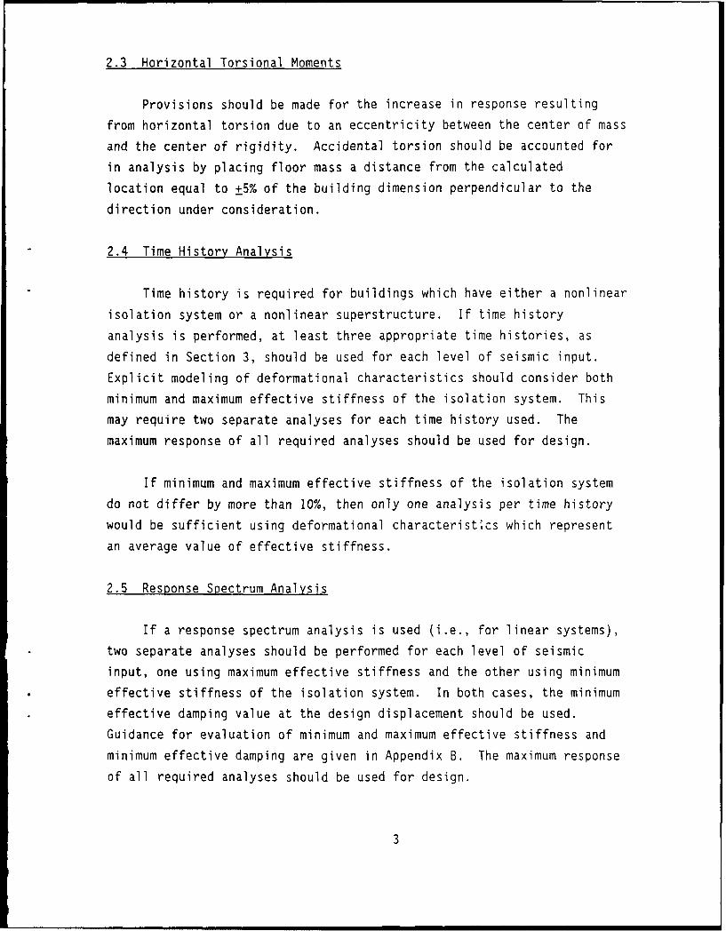
2.3 Horizontal Torsional Moments
Provisions should be made for the increase in response resulting
from horizontal torsion due to an eccentricity between the center of mass
and the center of rigidity. Accidental torsion should be accounted for
in analysis by placing floor mass a distance from the calculated
location equal to +5% of the building dimension perpendicular to the
direction under consideration.
2.4 Time History Analysis
Time history is required for buildings which have either a nonlinear
isolation system or a nonlinear superstructure. If time history
analysis is performed, at least three appropriate time histories, as
defined in Section 3, should be used for each level of seismic input.
Explicit modeling of deformational characteristics should consider both
minimum and maximum effective stiffness of the isolation system. This
may require two separate analyses for each time history used. The
maximum response of all required analyses should be used for design.
If minimum and maximum effective stiffness of the isolation system
do not differ by more than 10%, then only one analysis per time history
would be sufficient using deformational characteristics which represent
an average value of effective stiffness.
2.5 Response Spectrum Analysis
If a response spectrum analysis is used (i.e., for linear systems),
two separate analyses should be performed for each level of seismic
input, one using maximum effective stiffness and the other using minimum
effective stiffness of the isolation system. In both cases, the minimum
effective damping value at the design displacement should be used.
Guidance for evaluation of minimum and maximum effective stiffness and
minimum effective damping are given in Appendix B. The maximum response
of all required analyses should be used for design.
3

If minimum and maximum effective stiffness of the isolation system
do not differ by more than 10%, then only one response spectrum analysis
is required using an average value of effective stiffness.
3. SEISMIC INPUT
The site-specific ground motion should be based on appropriate
geologic, tectonic, seismic, and foundation material information. The
two levels of ground motion which should be considered are as defined in
Section 2-2312(d) 1A of Part 2, Title 24, CAC.
If time history analysis is used, the input time histories should be
selected from different recorded events and based on similarity to
source magnitude, foundation material and tectonic conditions. They
should be scaled such that their 5%-damped response spectrum essentially
envelopes the site-specific spectrum and does not fall below the site-
specf4- cpectrum by more than 10% at any period. Time histories
developed for sites within 10 km of a major active fault must incorporate
near-fault phenomena. Duration of time histories should be consistent
with the magnitude and source characteristics of an event.
4. LATERAL DESIGN FORCE AND DESIGN DISPLACEMENT
4.1 Isolation System
Displacements and forces used for design of the isolation system
and connections to structural elements immediately above and below the
isolation system should be 1.5 times the maximum displacements and forces
determined from dynamic analysis using the maximum probable earthquake,
or 1.1 times the maximum displacements and forces determined from dynamic
analysis using the maximum credible earthquake, whichever is greater.
4.2 Structural Elements Below the Isolation Interface
The strength of the elements below the isolation interface should
not be less than that required to sustain the lateral forces, as
determined by dynamic analysis for the max;,u,,, tcj;bf eL:,quakt
4

toaether with either a factored load of 1.2 times the dead load plus 0.5
times the reduced live load, or 0.8 times the dead load, whichever is
greater.
4.3 Structural Elements Above the Isolation Interface
4.3.1 Maximum Probable Earthquake
Using the dynamic analysis for the maximum probable earthquake,
structural members should be proportioned on the basis of their maximum
capacity, otherwise known as yield or limit strength design in accordance
with Section 2-2312(d) 1D, or on the basis of the deflection or drift
limitations set forth in Section 2-2307, whichever governs.
The base shear forces resulting from this analysis should be
compared with:
a. the base shear corresponding to the design wind load and
b. the yield level of a softening system, the ultimate
capacity of a sacrificial wind-restraint system, and the
static friction level of a sliding system.
If the dynamic analysis base shear force for the superstructure is
less than these limits, the design forces should be increased
proportionately so that the greater of the limits is satisfied.
4.3.2 Maximum Credible Earthquake
Using the dynamic analysis for the maximum credible earthquake,
ductile moment resisting frame structures should be designed so that
Section 2-2312(d) IF is satisfied.
For other types of framing, or for highly irregular or unusual
buildings, other criteria as determined by the project architect or
structural engineer and approved by the Office of the State Architect
5

will be required to demonstrate safety against collapse from the maximum
credible earthquake.
5 ADDITIONAL REQUIREMENTS
5.1 Isolation System
5.1.1 Back-up System
An alternate vertical loa'.-carrying system should be provided in
case of isolation system failure.
5.1.2 Environmental Conditions
In addition to the requirements for vertical and lateral loads
induced by wind and earthquake, the isolation system should be designed
with consideration given to other environmental conditions including
aging effects, creep, fatigue, operating temperature and exposure to
moisture or damaging substances.
5.1.3 Wind Loads
Isolated structures should resist design wind loads at all levels
above the isolator level in accordance with Title 24 wind design
provisions. At the isolator level, a wind restraint system should be
provided as necessary to avoid human discomfort within the building and
as necessary to limit lateral displacement in the isolation system to a
value equal to that required between floors.
5.1.4 Fire Resistance
Fire resistance for the isolation system should meet that required
for the building's columns, walls, or other structural elements.
6

5.1.5 Lateral Restoring Force
The isolation system should be configured to produce a restoring
force sufficient to ensure that the maximum offset of any isolator unit
does not exceed 33% of the design displacement. This requirement ensures
that the isolation system will not have significant residual displacement
following an earthquake, such that the isolated structure will be: 1)
stable; and 2) in a condition to survive aftershocks and future
earthquakes.
The isolation system need not be configured to produce a restoring
force, as required above, provided the isolation system is capable of
remaining stable under full vertical load and accommodating lateral
displacements equal to four times the maximum offset. Isolation systems
which are not configured to produce a lateral restoring should be capable
of accommodating displacements significantly greater than the design
displacement. Such displacements could occur in these systems as a
result of directional biases in vibratory response, earthquakes with
multiple segments of strong motion, or as a result of aftershocks.
5.1.6 Vertical Load Stability
The isolation system should provide a factor of safety of three (3)
for vertical loads (dead load plus live load) in its laterally
undeformed state. It should also be designed to be stable under the
full design vertical loads at a horizontal displacement which is the
greater of either 1.25 times the design displacement or four times the
maximum offset for softening systems and sliding systems, or 1.25 times
the design force for hardening systems.
The factor of safety of three for vertical loads was obtained from
the NBS Special Publication 577 entitled "Development of a Probability
Based Load Criterion for American National Standard A58."
The application of the factor of safety of three will be dependent
on the type of isolation system, but should be applied as a well-
7

defined limiting stress or strain value. For example, systems with
roller bearings may be governed by contact pressure, and systems with
elastomeric bearings, may be governed by the tensile strain in the
rubber.
An additional consideration for systems that incorporate an element
that can overturn (e.g., elastomeric bearing with a dowel shear transfer
mechanism) is the stability of the element at a horizontal displacement
which is the greater of either 1.25 times the design displacement or four
times the maximum offset. Tlie required check of stability will ensure
that there is sufficient margin prior to any loss of vertical load
support capacity.
5.1.7 Overturning
The factor of safety against global structural overturning at the
isolation level should not be less than 1.0 for the maximum credible
event. Local uplift of individual elements is permitted provided the
resulting deflections do not cause overstress or instability of building
elements.
The intent of this requirement is to prevent global structural
overturning and cverstress of elements due to local uplift for the
maximum credible event. Uplift in a braced frame or shear wall is
acceptable provided the isolation system does not disengage from its
horizontal resisting connection detail. The connection details used in
some isolation systems are such that tension is not permitted on the
system. If the tension capacity of an isolation system is to be utilized
on resisting uplift forces, then component tests should be performed to
demonstrate the adequacy of the system on resisting tension forces at the
design displacement.
If an isolation system is designed to resist tensile forces, then
this vertical load case should be included in the sequence of tests
specified in Section 6.2(2).
8
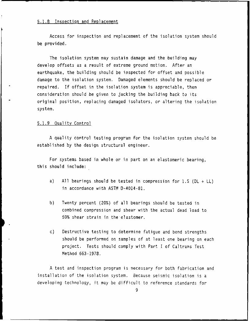
5.1.8 Inspection and Replacement
Access for inspection and replacement of the isolation system should
be provided.
The isolation system may sustain damage and the building may
develop offsets as a result of extreme ground motion. After an
earthquake, the building should be inspected for offset and possible
damage to the isolation system. Damaged elements should be replaced or
repaired. If offset in the isolation system is appreciable, then
consideration should be given to jacking the building back to its
original position, replacing damaged isolators, or altering the isolation
system.
5.1.9 Quality Control
A quality control testing program for the isolation system should be
established by the design structural engineer.
For systems based in whole or in part on an elastomeric bearing,
this should include:
a) All bearings should be tested in compression for 1.5 (DL + LL)
in accordance with ASTM D-4014-81.
b) Twenty percent (20%) of all bearings should be tested in
combined compression and shear with the actual dead load to
50% shear strain in the elastomer.
c) Destructive testing to determine fatigue and bond strengths
should be performed on samples of at least one bearing on each
project. Tests should comply with Part I of Caltrans Test
Method 663-1978.
A test and inspection program is necessary for both fabrication and
installation of the isolation system. Because seismic isolation is a
developing technology, it may be difficult to reference standards for
9

testing and inspection. Reference can be made to standards for some
materials such as elastomeric bearings (ASTM D4014-81 and British
standards). Similar standards are required for other isolation systems.
Special inspection procedures and load testina to verify manufacturing
quality should be developed for each project. The requirements will vary
with the type of isolation system used.
5.2 Structural System
5.2.1 Lateral Drift
The structure above the isolation system should conform to drift
criteria of Title 24 for the maximum probable earthquake.
5.2.2 Horizontal Distribution of Force
A horizontal diaphragm or other structural elements located
immediately above the isolation system should provide continuity between
individual isolators, should have adequate rigidity to ensure that the
building structure moves as a rigid body on top of the isolators, and
should be strong enough to transmit forces (due to non-uniform ground
motion) from one part of the building to another.
5.2.3 Separations
Minimum separations between the isolated building and surrounding
retaining walls or other fixed obstructions should be not less than 1.1
times the design displacement, four times the maximum offset, or the
minimum distance required for conventional structures.
5.3 Nonstructural Components
5.3.1 Components Above the Isolation Interface
Design of nonstructural component anchorage or bracing should be
consistent with the response of the particular structure under
consideration, as substantiated by analysis and/or tests for the maximum
credible event. Alternatively, anchorage or bracing may be designed
10

using the force requirements of Tile 24 for non-base isolated
structures.
5.3.2 Components Which Cross the Isolation Interface
All architectural, equipment and utility components which cross the
seismic interface should be designed to accommodate 1.1 times the design
displacement.
To accommodate the differential movement between the isolated
building and the ground, provisions for flexible utility connections
should be made. In addition, rigid structures crossing the interface,
such as stairs, elevator shafts, and walls, should have details to
accommodate differential motion at the isolator level without sustaining
damage sufficient to threaten life safety.
6. REQUIRED TESTS OF THE ISOLATION SYSTEM
6.1 General
The deformation characteristics and damping values used in the
design and analysis should be based on existing test data of the system
and confirmed by the following tests on a selected sample of the
components prior to construction. The isolation system tested should
include the ultimate restraint system and the wind restraint system if
such systems are used in the design. They should not be considered as
manufacturing quality control requirements.
The design displacement and forces developed from these provisions
are predicated on the basis that the deformational characteristics of the
base isolation system have been previously defined by a comprehensive
set of tests. If a comprehensive amount of test data are not available
on a system, then major design alterations in the building may be
necessary after the tests are complete. This would result from
variations in the isolation system properties assumed for design and
those obtained by test. Therefore, it is advisable that prototype
systems be tested during the early phases of design if insufficient test
data are not available on an isolation system.Ii

6.2 Seauence of Tests
The following sequence of tests should be performed on at least two
components of the full-si7e isolation system. The test specimens should
include the ultimate restraint system, the wind restraint system, as well
as the individual isolators, if such systems are used in the design.
Specimens tested should not be used for construction.
Each set of tests should be performed at three different rates of
loading. The rate of loading should correspond to 1/2, 1, and 2 times
the inverse of the isolated period, defined as a cycle of maximum
response for the maximum credible event.
1. Twenty fully reversed cycles of loading at a force
corresponding to the design wind force. If a sacrificial wind
restraint system is to be utilized, its ultimate capacity
should be established by test.
2. Three fully reversed cycles of loading at each of the following
increments of the design displacement or design force of
Section 4: 0.25, 0.50, 0.75, 1.0, and 1.25.
a. For softening systems, a displacement-controlled test
should be performed with the specified increments based on
the design displacement of Section 4.1.
b. For hardening systems, a force-controlled test should be
performed with the specified increments based on the
maximum force of Section 4.1.
Exception: If variations in effective stiffness
greater than + 15% occur in these three
cycles of loading at a given amplitude,
then three additional cycles of loading at
the given amplitude should be performed.
12

3. Ten fully reversed cycles of loading at 1.0 times the design
displacement.
If an isolator is also a vertical load carrying element the above
sequence of tests should be performed for each of three different
vertical loads as follows:
i) DL
ii) DL + 20% DL + 50% Overturning Force
iii) DL - 20% DL - 50% Overturning Force
For each cyclic test the force deflection and hysteretic behavior of the
test specimenr should be recorded. The vertical load carrying elements
of the isolation system should also be statically load tested to
demonstrate stability under a vertical load of 1.5 times dead load plus
reduced live load plus seismic overturning at 1.0 times the design
displacement.
The required sequence of tests will experimentally verify:
1. The assumed stiffness and capacity of the wind restraining
mechanism.
2. The variation in the isolator's deformational characteristics
with rate of loading, amplitude, and with vertical load, if it
is a vertical load-carrying member.
3. The variation in the isolator's deformational characteristics
for a realistic number of cycles of loading at the design
displacement.
Force-deflection tests are not required if similar-sized components have
been previously tested using the specified sequence of tests.
Variations in effective stiffness greater then + 15% would require
an additional 3 cycles of loading at a given amplitude to determine if
13

deterioration continues and variations greater than + 20% would be cause
for concern. The variations in the vertical loads required for tests of
isolators which carry vertical, as well as lateral loads, are necessary
to determine possible variation in the system properties due to vertical
ground acceleration and overturning force. Test set-ups may not be
capable of incorporating very low vertical loads because of static
instability in the test assembly. Consequently, a compromise may be
required to set a limit on the lower vertical load. Clearly, the
engineer will have to use judgement in selecting the appropriate dead
loads and overturning forces for the test system because these will vary
throughout the structure. As noted in Section 6.3, the design values of
the isolation system are based on the full DL tests provided the average
results of the other two vertical load tests do not vary by more than 10%
from the DL tests. This requirement is based on the premise that the
overturning forces are equal and opposite.
6.3 System Adequacy
The seismic isolation system test performance may be assessed as
adequate if:
1. The test force-deflection plots for all tests specified in
Section 6.2 have a positive incremental stiffness.
2. There is less than a 20% deterioration in the equivalent
stiffness for the six cycles of test (if six are performed at
a given vertical load specified in Section 6.2 (2)).
3. There is a less than 25% deterioration in the equivalent
stiffness and damping values for the 10 cycles of tests at a
given vertical load specified in Section 6.2(3).
An incremental reduction in load resistance over a displacement
range greater than 1/2 inch is indicative of deterioration or
instability, neither of which can be tolerated for the specified tests.
If this occurs, then the tests should be extended so that at least
14

another 3 cycles of loading are required with a 25% increase in the test
amplitude or force at which this phenomena was observed. If reduction in
load resistance continues, then the system is inadequate.
If the variation in stiffness and damping values for a given
vertical load are less than 25%, then the system is adequate. If the
variations are greater than 40%, then the seismic isolation system should
not be used. Variations between 25% and 40% would be cause for concern
and should probably require tests on additional isolators.
7. MONITORING AND INSTRUMENTATION
The isolation system should be monitored for the life of the
build'ig, and access for inspection and replacement of the system should
be provided. A program for monitoring should be established by the
person responsible for the structural design and would be submitted for
approval with the plans and specifications. The monitoring program
would become a part of the approval. The implementation and maintenance
of the program should then be the responsibility of the owner of the
building. Approval and enforcement of this program would be delegated to
the Office of the State Architect by the Office of State Health Planning
and Development.
As a minimum, the program should include the following:
1. Approved instrumentation would be provided and maintained to
record structural motion at appropriate locations within the
building and at the levels of the bottom and the top of the
isolators. Verified reports confirming adequate maintenance
and monitoring of the instruments should be submitted to the
Office of the State Architect semi-annually. Hard copies of
accelerograms should be submitted to OSA within one month of a
recorded event. Records for significant events as described in
2. should be accompanied by appropriate response spectra.
2. Visual inspections should be made by a Structural Engineer
after every significant earthquake (defined as an earthquake
15

large enough to produce a ground motion peak acceleration of
0.2g or larger or a displacement record of two inches or
greater at the base of the isolators). The inspection should
consist of viewing the structural performance of the building,
the records produced by the building instrumentation, and a
visual examination of the isolators and their connections for
deterioration, offset, or physical damage. A report of such
inspection, including an analysis for the recorded ground
motion and conclusions on the continuing adequacy of the
structure, should be submitted to OSA for review within three
months of such an event.
3. Selected isolators (approximately two percent of the total, but
not less than two) should be removed temporarily at intervals
not to exceed 10 years for physical testing. Tests should
determine lateral stiffness under the design dead load and
design displacement. The results of these test should be
compared to the data obtained by the qualification testing. If
the mean value of the material properties determined by the
testing vary by more than one standard deviation of the
qualification test data from that data, the analysis of the
structure-base isolation model should be repeated to verify
that the design is still valid. A report of the results of
testing, including conclusions on the continuing adequacy of
the structure and isolators, should be submitted to OSA for
review within three months of the testing.
16

APPENDIX A
Suggested Criteria for Determining Nearly Elastic Structural Behavior
The following concepts have been extracted from "Seismic Design
Guidelines for Essential Buildings", Department of the Army, TM5-809-10-
1. If additional clarification or examples are required, then reference
to that document is recommended. These concepts are incorporated solely
for the purpose of defining when linear model of the superstructure is
appropriate for dynamic analysis.
Nearly elastic behavior is interpreted as allowing some structural
elements to exceed their strength level within specific limits. If the
structural response is within the limits required for nearly elastic
behavior, then the structural deformations may be assumed to be equal to
those found by the use of a linear model of the structure. For a
structure that has a multiplicity of structural elements that form the
lateral-force-resisting system, the yielding of a small number of
elements will generally not affect the overall elastic behavior of the
structure if the excess load can be distributed to other structural
elements that have not exceeded their yield strength.
A linear model of the superstructure is acceptable if the procedure
that evaluates overstresses of individual elements, outlined below, is
followed, and the limits given in Table A-i are not exceeded.
1. Perform analysis of the structure using the appropriate maximum
credible earthquake response spectrum or time histories.
2. Calculate the forces on all of the structural elements. Load
combinations are given below and are in Section 2-2312(d) iD.
These forces will be defined as the demand forces and denoted
with subscript D (e.g., MD, VD, FD).
Demand Force = 1.2D + O.5L + E
Demand Force = O.8D + E
17

where:
L = reduced live load
E = earthquake force from (1)
3. Calculate the elastic capacities of all the structural elements
in the same force units used in paragraph (2) above. These
forces will be defined as the capacity forces and denoted with
the subscript C (e.g., MC , VC, FC).
The elastic capacity is set to equal the strength capacities of the
structural components.
a. Reinforced Concrete: The strength capacity for
reinforced concrete elements will be given by the ACI
Building Code 318.
b. Structural Steel: In lieu of strength design criteria
for structural steel, the working stresses for
ordinary or nonseismic construction may be increased
by 70 percent to provide the strength capacity; for
example,
fa + fbx + fby < 1.7Fa Fbx Fby
c. Reinforced Masonry Design: In lieu of a strength
design criteria for reinforced masonry, working
stresses for ordinary or nonseismic construction may
be increased by 70 percent to provide the strength
capacity; for example, fa < 1.7 Fa.
d. Connections: All connections that do not develop the
strength of the connecting members will have a
strength reduction factor of 0.75. This reduction
factor will be applied to the strength capacity of
the connection material.
18

4. Calculate the ratio of the demand forces to the capacity forces
of all the structural elements. These ratios will be defined
as inelastic demand ratios.
5. Review the inelastic demand forces for uniformity, symmetry,
mechanisms, and relative values. Compare values to limits set
forth in Table A-I. If any of the following conditions exist,
a linear model representation of the structure is not
acceptable and the structure must be analyzed by developing a
simplified inelastic representation of the building which
incorporates the progressive inelastic deformation of the
structural members.
a. Exceeding the inelastic demand ratios of Table Al.
b. Unsymmetrical yielding, on a horizontal plane in the
structure, that will decrease the torsional
resistance.
c. Hinging of columns at a single story level that will
cause a mechanism.
d. Discontinuity in vertical elements that can cause
instability or fracture.
e. Unusual distributions of inelastic demand ratios.
6. Engineering judgment is required for the structural evaluation
of the post-yield analysis. If the review of the inelastic
demand ratios satisfies the requirements of paragraph (5)
above, it may be assumed that the inelastic deformations can be
adequately approximated by elastic analysis.
19

A-I - Limits on Inelastic Demand Ratios
Building System Element Demand Ratios
Steel DMRSF Beams 2.0Columns 1.25
Braced Frames Beams 1.5Columns 1.25Diag. Braces 1.25K-Braces 1.0Connections 1.0
Concrete DMRSF Beams 2.0Columns 1.25
Concrete Walls Shear 1.25Flexure 2.0
Masonry Walls Shear 1.1Flexure 1.5
20

APPENDIX B
Determination of Effective Stiffness and Damping
The intent of these requirements is to ensure that the deformational
properties used in design result in the maximum design forces and
displacements. For determining design displacement, this means using the
lowest damping value and minimum effective stiffness of the isolation
system. For determining design forces, this means using the lowest
damping value and maximum effective stiffness of the isolation system.
B.1 Stiffness and Damping Properties
The effective stiffness, and equivalent viscous damping to be used
to determine the design base shear forces and displacements by response
spectrum analysis may be determined as follows:
1. The minimum stiffness, kmin, to be used in the determination of
the design displacement should be based on the average of the
lowest three effective stiffness values determined from each of
the 10 cycles of loading in the test sequence specified in
6.2(3) for the dead load test, provided these lowest three
values do not differ by more than 15%. If they do, then the
lowest value should be used.
2. The maximum stiffness, kmax, to be used in the determination of
the design base shear force should be based on the average of
the highest three effective stiffness values determined from
each of the 10 cycles of loading in the test sequence specified
in 6.2(3) for the dead load test provided these highest three
values do not differ by more than 15%. If they do, then the
highest value should be used.
3. The equivalent viscous damoing, if it is to be used in a linear
system in the determination of the design displacement, should
be based on the average of the lowest three equivalent viscous
21
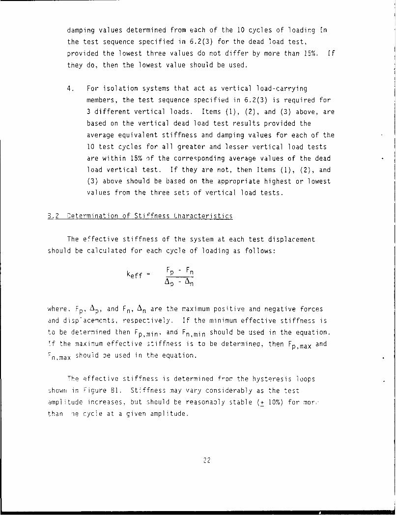
damping values determined from each of the 10 cycles of loading In
the test sequence specified in 6.2(3) for the dead load test,
provided the lowest three values do not differ by more than 15%. If
they do, then the lowest value should be used.
4. For isolation systems that act as vertical load-carrying
members, the test sequence specified in 6.2(3) is required for
3 different vertical loads. Items (1), (2), and (3) above, are
based on the vertical dead load test results provided the
average equivalent stiffness and damping values for each of the
10 test cycles for all greater and lesser vertical load tests
are within 15% of the corresponding average values of the dead
load vertical test. If they are not, then Items (1), (2), and
(3) above should be based on the appropriate highest or lowest
values from the three sets of vertical load tests.
B.2 Determination of Stiffness Characteristics
The effective stiffness of the system at each test displacement
should be calculated for each cycle of loading as follows:
keff FpFnAP - An
where, Fp, AP, and Fn, An are the maximum positive and negative forces
and displacements, respectively. If the minimum effective stiffness is
to be determined then Fp,min , and Fn,min should be used in the equation.
Tf the maximum effective stiffness is to be determined, then Fp,max and
Fn,max should be used in the equation.
The effective stiffness is determined from the hysteresis loops
shown in Figure BI. Stiffness may vary considerably as the test
amplitude increases, but should be reasonably stable (+ 10%) for mor,
than ie cycle at a given amplitude.
22

B.3 Determination of Damping Characteristics
The equivalent viscous damping ratio (S ) for systems with velocity-
related damping for each cycle of loading shall be calculated as:
s I Area of Hysteresis Loop
2 -7r keff A max
The determination of equivalent viscous damping is reasonably
reliable for systems whose damping characteristics are velocity-
dependent. For systems that have amplitude-dependent energy-dissipating
mechanisms, significant prublems arise in determining an equivalent
viscous damping value, since it is difficult to relate velocity and
amplitude-dependent phenomena. The equivalent viscous damping concept
can only be used for linear systems since nonlinear systems must be
modeled explicitly.
23

FORCE
kmax= Fpmax Fnmax
kn p,min - nmin
A DIPLC
p an
FIGURE B-1: EXAMPLE FORCE-DEFLECTION TEST CURVES USED TO DETERMINEMAXIMUM AND MINIMUM EFFECTIVE STIFFNESS
2.'

January 15, 1988
FORCEO C
kmax
Fpa ,mpaaxx Fnma
Fi k min
6 p ISPLACE
kmax = Fp,max - Fn,max
ap - n
kmin = gp,min -Fn,min
FIGURE B-i: EXAMPLE FORCE-DEFLECTION TEST CURVES USED TODETERMINE MAXIMUM AND MINIMUM EFFECTIVE STIFFNESS
25

DISTRIBUTION LIST
A F I(KW4 SS,/l)E. ()nizuka A Fi~. (A: 323 (TS ILI (I j0.). Nlather AlItI.( V. All I D) I I IIci I i.W'right- Patterusoii ,FII. Oil: ,\FII'D'I. \\'iiht-I',tterson AFBI. O lIL (ip 111 IoIhiid. S;oijIa.rb.
AF 110 ESD/AVMS, Hlanscomn AFB, MA: [51)1)1:'., I lanscoi ,\IB. \lIAAFB 42 ('ES/Rcady Off. Lo ring AFEB. NI--: 82nd A\l) l k:kC illihnis AVII A/.: 11 ( NACD I)1I1. SLIM
AFR). ILAFFS( 'TST (Libraryl), Ivndall iNFII. 1:1.ARMY 416th ENCONI. Akron Sfrvey Tmn. Akioii. OIL ( L( ()N R&D I)lccli I i. 1:1 %lonmnouth. 's-1
CEIISC-FU-N ( Krajewski. Ft Belvoir. VA: Ill I( 7111 AI( ( Ross). ( irlimn'ib. (it . HO)IAIDAEN-ZCM). Washington, I)C: POJII)-O. Okinima. Japan
ARMY I3ELVOIR R&ID (EN SIRIIE-IIIARF. Ft lelvoir. VAARMY CERL CECER-EMFE ([Haves), Champaign. IL: (I/:RI-/.N. (liunpign. II.: hi,:,, lhaii,aign. 11.ARMY DEPOT Letterkenny. S1)SLF-SF. (hamnbersbnrg. PAARMY EHlA liSIIB-EW. Abcrdccn Proving (irnd. MIDARMY ENGR DI1ST (ENPS-FD-SD. Seattle. WA: I.MV(CO-A I3Ie,,tle. VitKsboIri!. \S: ji,.,.- cIcttc. \% A:
Phila . Lib. Philadelphia. PAARMY ENG;R D)IV ('EEUD-ED-I A (McVaN~). Frankfurt. - ,: (I I I)-FD)-(S. I limits\e. A- Ix D1-SY
(Lovd). Huntsville. AL: IINI)ED-SY. tLIuncSvifle. Al-ARMY EWES (iP-EC (Webster), Vicsburg. MS: Libr;,r\. Vicksbourg MN: WLNCI)-l' (Nlclbyf). \ieksbiire. 515:
WESCV-Z (Whalin). Vicksburg. MS: WFSOPl-F. Vicksburg. M4sARMY LMC Fort Lee. VAARMY MISSILE R&D) (MD Ch, Does. Sci Into 0'r. Arscniw. Al.ARMY MMRC I)RXMR-SM (Lenroc). Watertown. MAADMINSUPI PWO. BahrainB3UREAUI OF RECLAMATION D-l512 ((GS IePU N). lOcnvcr. U0(1K' Code If0. Davisville. RI: ('ode 15. Port I lueneiCI. ( A: (ode 55. Port I lunineCII. CV\ ( ode 43c.
(iulfporr. NKS Library. IDavisville. RI: PW() ((odc 400),. ( ;iltpiirt .NK5 l'W( (Code so). Port I uliim.('A: Tech Library. Giulfport. MS
(NA Tech Librarv. Alexandria. VACOGARI) R&DC Library, (irolon, ('ICONICILANT Code S3T. Norfolk. VA(OMDTI ('OGARD Librarv. Washinigton. IDCCOMFILEACT PWO. Saseho. JapanCOMNAVSIJPPFORANTA R( ICA DIl. P'V0'. (briktchutch. N/(OMNAVSURF ('ode N42A. Norfolk. VA('OMOCEANSYS Lant. ('ode N9. Norfolk. VACOMTRA Lint, SCE. Norfolk. VAI)FSC OWE, Alexandria. VAI)IA I)B-6E I Washington. D)C: DB-6F2. Wazshington. D)C:\'(). WP , .,sijnewon. D)CDIRSSP Tech Lib). Washing~ton, D)CDOD DFSC-FE. Cameron Station. Alexanfriai. VA: [spllos saifet% lird fI hb. Wisflinim). D)CDOE Wind/Ocean lecch D)iv, lobicco. NilDI~C Alexandria. VAD'IRCEN ("ode 172. lctfiesda. Nil) ('ode 41)11. ficfid. Nil)FAA (ode APM-740t (Ioniitaf. Washiniton. D)(GiI)EP OIC. Corona. (AGISA Lih Engr, fir. PUB1. Washington. DC(
- I LIBRA RY OF CO(NG RI/SN Sci & leebh Di%, Wasfiington, IN(iA RC)R [ASI: ( ode 4.01. Camp Pecndlecon. (A: ( odel -Ii(,. ( aiinp lcc. NC 'PA( Il\( ),Iii lluiit
JA: PW( ). (Camp Lcelune. N(': I)WO. ( jimlp 1['endleto,, ( A I. Ip linICI, JA1.MARCORPN FIRST FSS(i. Friar Stipp 011fr. (amip lI'edlecon. ( ANICAN PIW(. Yumna. AzN511 H PW( (SaL-han). ILarstow. CAN
M RI) l'W( Sin IDieg. ('A,I( RD)A( MI & L D)I% Qiantico. VA, I'\( ). ()iaco. \ ANAFI AROI((. Midv~a\ Isfindif)r. I ngiie Dix, P l'I). Visagi hpi11

NAS Chase FId. Code 18300,) Beeville, TX: C'hase Fld. PW(). liccallic. I X: C ode 110, Adak. AK: (COdIC IS.Alameda. (CA: ('ode 1833. Corpus C'hristi. TX: Code 70. South WeC mouth. MA: ('ode 8, PalUxcrnt River.MD: C'od,: 83. Patuxent River. MID: Miramar. PWO. San IDicgo. ('A: NI. (OdIC I 3. San IDicgo. C'A: FacMgmt Offe. Alameda. CA: PW Engrg (Branson). PatUXent River. MID: PW() (C'ode 182) Bermuda:' PWO.
Adak. AK: PWO. Cecil Field. Fl.: PWO. D~allas, IX: l'\N . (ilenvicv. Il.: PWO. Kef-litik. Iceland: PWO.Key West. FL: PWO. King~sville TIX: PW(). New Orleans. LA: IWO. Sigonclla. Italy: PWO. SouthWeymouth. NIA: SCIE. Barhers Point. III: SCE. ('uhi Point. RIP: Whiting Fld. PWC). Milton. Fl.
NAVAIRDEVCEN Code 832. Warminster. PANAVAIRENGCIEN ('ode 182. Lakehurst. NI: PWO. Lakehurst. NJNAVAl RIESTCEN PWO. Patuxent River. MD)NAVAUDSV('HO D~irector. Falls CLhurch VANAVAVNDEPOT Code (40). Pensacola. Fl.NAVCI-APGRU Code 64). Williamshurg. VANAVCOASTSYSCEN ('O. Panama City. Fl_: ('ode 2360). Panama City. FL.: C ode 7404. Panama City. FL: Tech
Library. Panamna City. FLNAVCOMMSTA (Code 4041. Nea Mlakri. CGreeceNAVELEXCEN DET. OIC. Winter Harbor. MENAVEODTIECHCEN Teeh Library. Indiatn Head. Nil1)NAVFAC PWC) (('ode 5(4). Brawdv Wales,. UK: PWO. Oak liarbor. WANAVFACENG('OM Code (444 Alexandria. VA: C'ode 043. Alexandria. VA: (Code 03T (Essoglou I. Alexandria.
VA: Code 044A, Alexandria. VA: ('ode 444A I. Alexandria. VA: COdeC (JA ID. Alexandria. VA: Code 044A3.Alexandria. VA: Code (44A3('. Alexandria. VA: (Code 0631. Alexandria. VA: C'ode 407, Alexandria, VA:('ode 047M (Gross). Alexandria. VA: ('ode 049NI124 ( Lib). Alexandria. VA
NAVIFA('ENGCOM - (HES DIV. FPO-IPL_. Washington. DCNAVFA('ENCOM -LANT DI\'. Br Ole. D~ir. Naplcs. Italy: ('ode 1112, Norfolk. VA: Library. Norfolk. VANAVFACIENG('ONI -NORTH DIV. C'ode ((4. P'hiladelphia. PA: ('ode (44AL. Philadelphia. P'ANAVFACIENGCOM -PAC DIV. ('ode 049P, Pearl IHarbor. III: LibraryN. Pearl H arbor. IIINAVFACENGCOM - SOUITH DIV. ('ode 04-A3. Charles;ton. SC: ('ode 1112. Charleston. SC: ('ode 4416.
C'harleston. SC': Library. Charleston. SCNAVFA('ENGCC)Mv - WES'T DIV. ('ode 0(4A2.2 (Lib). San Brutno. ('A: ('ode 44413. San Bruno, CA: ('ode 40(8.2
(Jeung) San Bruno. ('A: Pilc NW Br Offe. C'ode C'544. Silverdale. WA.NAVFAC'ENGCOM C'ONTRACTS AROICt . Uuantico. VA: C'ode 40(0. Portsmouth. VA: ('ode 923. Everett.
WA: DROC(C. 1.emoore. C'A: Earle. RC)IC'C'. Colts Neck. NJ: North Ila%. C'ode I((42.AA. Vallejo, ('A:OC'C'. Guam: 0C'C ROI'C'. Norfolk. VA: OIC'C"ROICC. Virg~inia Beach. VA: ROICC. C'orpus C'hristi.TX: RoCC'. Crane. IN: ROI'C'. Ketlaik. Iceland: ROICC. P'oint Mugu. ('A: SW Pac. 01CC. Mlanila. RP
NAVFUEI_ I)EU OIC'. Yokohama. JapanNAVI ICSP ('O. Millington. 'IN: I Id. Fac Mgmt. ('imp Pendleton. ('A: SC'E I Knapowski I. Great Lakes. IL:_
SC'E, Pensacola. FLrisVMAG SC'E. Subic Bay. RIPNAVMARC'ORESCEN LIJ1.D16 is Raleigth. NCNAVM/EDCOM NWREG. Fac Engr. PWI). O:likland. C A: PACRE~i. C'ode 22. Birlbcrs Point. III: SIF REG.
I-d. File Ngmt De'pt. Jacksonville. FL.: SWREG. fIcad. I-ac Mgmrt IDept. San D~iego. ('A: SWREG. SCE,San Dieg~o. ('A
NAVCEAN('OMCEN CO. (juamn. Mariana IslandsNAVOC'EANC) ('ode 621H44 (M Paige). Hit\ St. ILouis. NISNAV()CEANSYSCIEN Code 9642B1. San Diego. ('ANAVPGSC'OL PWC). Mvonterey. ('ANAVPIIIBASE PWO. Norfolk. VA: SCE. San D~iego. CANAVSC'OI.(EC'OFF C'ode ('35. Port Hlueneme. C'ANAVSCS( A)L PWO. Athens. (;ANAVSEAC'ENPAC ('aide 32. San D~iego. ('ANAVSEASYSCOM ('ode PM\,S290I.22 0. Rekas(. Washington. DCN A\NSI IIPREI'FAC' Lihirarv. Gjuam : SCE. Subic P.' SCE . Yokosu1kd. JJl1ipatNA\'SI IPYI) ('ode 2442.4. Long Beach. C A: C'ode 2(02.1 (Libritrs . Bretnerton. WA: ('odc 440. Portsmnouth.
NilI: C*ode 443. Bremertorn. WA: Lbahrs. 'ortsmuoitb. Nil %i:Mre Islil. C'ode 202.13 IVa'llejo. ('A: MarcIsland. ('ode 280,. Vallclo. C'A: Marc IslatI. I'W( ). Nllejo. ('A: Norlolk. ('ode 4404 'rtot. VA:PWo. Brcmecrton. \ki
NAVS'l A C (). I .i'ng Beaich. CA: CO,) Roosevelt Roiids. P'R ' Code N42I 4. Nmapoin Fl.: Lttgr Di\, PWI).
( ihaN AVS. l'lAC I IN .N ipc.lk
N\VSiL PPIF-,( C 'Itid 'Alio, cliIbar Ioh ilrt\ )iee( (aii
NAVY l'S' So()"I ( (Ie W)". N ashil~litt.l Do
N*\~N ( 'I 1,2! 1 illci . DIlito. VA,. M) I.- N\hltr ()ak I ah ( odo NNY I. Silsem Spir. \11)

NAVWARCOL Code 24, Newport. RINAVWPNCEN AROIC. Chini.La . CA: PWO (('ode 266). China Lake. (ANAVWPNSTA Code 09213 (Hunt). Yorktown. VA: Dir. Maint Control. P1WI) (Concord. (A: I'WO. Charlest(on.
SC; PWO. Seal Beach. CA; PWO. Yorktown. VANAVWPNSUPPCEN PWO. Crane. INNETC Code 42, Newport, RI: PWO. Newport. RINCR 20, CONEESA Code II IE (MeClaine). Port Hueneme. CANMCB 3. Ops Offr, 40, CO; 5. Ops DeptNOAA Joseph Vadus. Rockville. MDNRL Code 2511,. Washington, DC: Code 4670 (13. Faraday)). Washington. DC(NSC Code 54.1, Norfolk. VANSD SCE. Subic Bay. RP
* NUSC DET Code 2143 (Varlev). New London. CT: ('ode 44 (RS Munn). Ncw London. UTF: (ode IA 131. Ne\%London. CT: Lib (Code 4533). Newport. RI
PACMISRANFAC HI Area. PWO. Kekaha. HIPHIBCB 1. CO. San Diego. CA: 1. P&E. San Diego. CA: 2. ('0. Norfolk. VAPMTC Code 10118, Point Mugu. CA: Code 50). Point Mugu. CAPWC ACE Office. Norfolk. VA: ('ode I1l. Great Lakes. IL. Code 10., Oakland. ('A: COdeC 101 I Librars .
Oakland. CA: Code WI I. Pearl Harbor. HI: C'ode 10)2. Oakland. C'A: ('ode 1234C'. San D~iego. ('A. (ode30, Norfolk. VA: Code 4WX. Great Lakes. IL: ('ode 400, Oakland. ('A: (ode 400. Pearl H arbor. III ('Code4(W, San Diego. CA; Code 420). Great Lakes. IL: ('ode 420). O,ikland. ('A: ('ode 42013 (Waid). Subic Bay.RP: Code 421 (Kaya). Pearl Harbor. HI: Code 421 (Quin). San Diego. ('A: ('ode 421 (Reyno1ldS). SaniDiego. CA: Code 422. San Diego. CA: Code 423. San Diego. ('A: ('ode 424. Norfolk. VA: ('ode 430) (Ksi0.Pearl Harbor. HI Code 5W,) Great Lakes. IL: Code SIX). Oakland. ('A: Librar\ (('ode 134). Pearl Hlarbor.HI: Librarv. Guam. Mariana Islands: Library. Norfolk. VA: Librarv. Pensacola. Ft.: ILibrars . Yokosuka.Japan; Tech Library. Subic Bay. RP
SPCC PWO (Code 08X), Mechanicsburg, PASIBASE Bangor. PWO (Code 8323). Bremerton. WASUPSI-IP Tech Library. Newport News. VAUS DEPT OF INTERIOR NatI Park Svc, RMR!PC. Denver. COUSDA Ext Serv (T Maher). Washington. DC: For Svc Reg 8. (Bossers). Atlanta. (6A: For Skc. Reg Bride
Engr. Aloha. OR; For Svc. Tech Engrs. Washington. DC'USNA Chi. Mech Engrg Dept. Annapolis. MD: Ocean Engrg Dept (Mc('ormiek). Annapolis. MD-: PWO.
Annapolis. MDCALIFORNIA STATE UNIVERSITY C.V. Chelapati. Long Beach. CACATH-OLIC UNIV of Am. CE Dept (Kim). Washington. D)CCITY OF BERKELEY PW. Engr Div (Harrison). Berkelev. CACITY OF LIVERMORE Dackins. PE, Livermore. CACLARKSON COLL OF TECH CE Dept (Batson). Potsdanm. NYCOLORADO STATE UNIVERSITY CE Dept (Criswell). Ft Collins. ('0CORNELL UNIVERSITY Civil & Environ Engrg (Dr. Kulhawy). Ithaca. NY: Librar\. Ithaca. NYDAMES & MOORE Library. Los Angeles. CAFLORIDA ATLANTIC UNIVERSITY Ocean Engrg Dept (Su), Boca Raton. FLFLORIDA INST OF 'TECH CE Dept (Kalajian). Melbourne. FLGEORGIA INSTITUTE OF TECHNOLOGY ('E Scol (Kahn). Atlanta. (GA:, (CE Scol (S%%anger). Atlanta. GA.
CE Scol (Zuruck). Atlanta. GAINSTITUTE OF MARINE SCIENCES Library. Port Aransas, T'XJOHNS HOPKINS UNIV CE Dept (Jones). Baltimore. MDLAWRENCE LIVERMORE NAi'L LAB FJ TokdrL. LiVermore. C:A: Plant! Engrg Lib (L.-654). Livermore. ('ALEHIGH UNIVERSITY Linderman Library. Bethlehem. PALONG BEACH PORT Engrg Dir (Allen). Long Beach. ('AMICHIGAN TECH UNIVERSITY CE Dept (Haas). Houghton, MlMIT Engrg Lib, Cambridge. MA: Lib. Tech Reports. C'anmbridge. MA: RV Whitman. ('ambridge. MANATL ACADEMY -)F SCIENCES NRC. Naval Studies 13d. Washington. D)CNEW MEXICO SOLAR ENERGY INST Dr. Zwvibel. Las (raIces. NMNEW YORK-NEW JERSEY PORT AUI'H Engrg Dept (Yontar). New% York, NYOREGON ST1ATE UNIVERSITY ('E Dept (flicks). Corvallis. ORPENNSYLVANIA STATE UNIVERSITY Gotolski. Uiversity Park. PA: Rseh lab (Snyder). State C( olce.
PAPORTLAND) STATE UNIVLRSI~ir Engrg Dept W igliori). Portland. ORPURDUE UNIVERSITY ('E Seol I Leonards). W. lafayette. IN: InerL I Il. kk. I itaseit. INSAN D)IEGO) PORT Port Fac. Proj Engr. San D~iego. CASAN IIEG( STATE UNIV CE Decpt I Krishnunioorh Il%. San I ieeo. C A

SEATFLE PORT W' Ritchie. Seattle. WASEATLE UNIVERSITIY C'F Dept (Sch\%ilejlJr. Seattle, WASOUTiiIW\ESI' RS'I I I NSTi Energetic Svs D~ept I Kp~iail. San Antmoo IX. King. San Antonio. IX: NM.
Polo~n. San Antonio. IX: Mlarchaind. San Antonio. IXSTATE UN IVERSI FY OF NELW YO RK (F E Dept I Rciihorn I. Bll ilo. NN: 11 I cpt. Ihil ilo. NYTEXAS A& N NIVERSITY (T D~ept I Machenichi I. C 'ollcvc Stlit iii IVN ClI )cpi I NicdM/ ecki. College
Station. TX: Oceani Engr Proj. College Station. IXLTNIVERSIIVY OF ('Al FORNIA CEF lDept (Lensecs). Ilerkelex C A. CI' Dept (GC evmick I. Ilerkcele CA, (T
Dept (Tavlor). Das is. CA: C 1: Dept ( Williamson. Ilerkcles (A. Nas~i :11,ch D ept, hrciles~.N C A
UN IVERSHlY OF HIA RITC RI (T Icept IKsisan Wcst I tartlord. C 'LU7N IVE R SITY O F HAWAII (1L Dept IC hitil. Hooiluilu. III: %laitiii. l~la~ IfIiolliih. III: OC lera Illgrg
Dept I Ertekin I. I lonoLIj. FMIUNIVERSITIY OF ILLINCOIS I~ihrzirs . 'rhaina. II.: NIl. I:iisoii. Ui rait. II.i Nlet/ Rcd Rim. t.'hmiii. 11IiNIVERSII'Y C)F NIICItICAN (T Dept I Riehart I. Ann ,\rhii. %ilUNIVERSITY C F NEBlRA\SKA I'olar Ice Coring ( 111ce. L inciiln, NI:I.NIVERSIFY C F NLW MEIX ICO( 111I. Schreycr. AlbikLIerUCL1C. N NI Nrvi FRI (1I)Iei . A1111LiLrklclieN Ni:
NNIERI W~alk) . Alhbumuerqu. NMI: NNlILRI Ieih.Albuquerque. NNIUNIVERSITY C)l PENDVAI ~pt Of Arch (I). NeCt'lcmirv. Philaidelphia. P'A
UNIVERSHlY (F Il-XAS (TI- Icpt (Thornpiinl. A'ustin, IX: ConstrLIction Inutr ns.,\sin. 'IX! I:(J4.8 I Brcen I. Austlin. IX
UNIVERSITY OF WASI INCION CE D~ept NMitick . Seatle. W'A
UNIVERSITY (V WISCONSIN Great lkekS Studies ('enl. Nlikditkee. WI
WASINGI'C N DIIM S. C FE P1IS I shihara I. Seatle. WAADVANCED) IECHINC .C Y. I NC COp,, (en N12r (1I Idn1r. C antorillo. CAANMERICAN (C)NCREFIT INSTIllI.IL Librar%. Detrit. NilARVID) CRAN'l & ASSO)C C)I irpia. W\A,\I*I,.ANII(' RICHFIELD) CO RE Smith, Dallas.IXIA'ITEFIT .1) Frink. C 'olionh1us. COIIIIEC'IIII. CIVIL. INC' Wooltin. San Franeisco. CABElIII IENI SILEEI- U. C ECngrg D~ept I Disniuke I. Ilethleltet PABRITISHI ENIFIASSY Sei & leeb IDcpt I Wilkinsl. Wo,ishigtoii. W)B ROWN & RCOIMI Ward. I boston. I'XCANADA 'iatCUr Dce C'hamnplain. I).S.A.. Niatane. CanadaC'HEVRC)N Cff- I. D RSCI I (COI Strieklind, l.a IHabra, C'ACILDS ENCRC CORP KNI. Childs. h. NlCdticld. NIA\CLARENCE R t]ONES. COCNSULIlN. 1.11) AugPusta. CGACOLLINS ENCGRG. INC NI Carlich. Chicago. 11.CCONRAD) ASSOC C' isoi. Vait Nus s. C'A(C NSC)LR IC VWNSF.NI) & ASSOC Schraimm. C hIicigii. 11.(C NS'IRUC"IC )N *1ILCI IIABlS. INC G. C ortes. Skiikie. 11.D)AVY DRAVC) Wright. I'ittshu in. PAILFINGHAM,\N C'ONS!'R (CORP' 011)~ . 1: II IC. I Ioniiul. III
EVAL.UATIION ASSO C. INC NIA\ LLdelc. King ut 'russii. PA,CJRUI iAN AI\ R( SPAC'L C *C )I [cl Inlo (tr. Itcthpii~e. NYIIAITY Lk ALDIRICHI. INC. I.C. DITnn. Cambr11id~gC. NiAHIAYNES & ASSOC If. I lisnes. IT, Iokiklld K AIRSCH'I & COI 1. I lirseb. Sin IDicgo, C A
11.1 I)II6iFNKCII.I ASSOC Ck W Nitdiigl. Sanl Irancisco. CA1lt,161ILS AIRCRAHt (C 0 il IIiic Cii e. 1:1 Scguindii.C \
INI l. NiARI I NlILl. INC I) Walsh. San Pedrii. (.AIRI,-1I'I I) Input Proc him iR. Ilanlirt. Leqan. MINIC )I IN.1 %1* N C 1.1 N ASSC IC I ibrars . Nes York. NY
FIN Of15 I IORFI LNCR ICC I' (him. Sain [riitcisc C A,
L INDA, ItAtI. 1,IIIRARt * lc D~ept- Kansas C its. %IC0
MiARCA Il ION C)III C C I CiMiit'l. I Iiitoii IXNMIARI I IC( I I[A NC IZ~iinogbiic. rAtitii. I XMCI (1.. I I.I.\DI I NGoRS. INC liri. Iliiistimi. IXMOBIII R&D) C (RI' C llliirc I igre 1 0b 1lli.II IMW.RII K N()Il,\ & ,'SoC Ilonoliilti. IIINI kk I A\I \SND N/ licict Rsrb .\sst . IiiiiNtIIN & ASSS(C A5 C \iml.V ~ti '\I

PACIFIC MARINE TECH (NI Wagner) D~uvall. WAPILE BUCK. INC Smoot. Jupiter, Ft,PMB ENGRG Couli. San Francisco. (CAPRESNELL ASSOC,. INC' DG Presnell. Jr. [.ouisville. KYSANDIA LABS lihrcry. Livermore. (ASARGENT & HIERKES. INC JP Pierce. Jr. NcA Orleans.,, LA
SUDI ARABIA King Saud Univ. Rsch (Cen. Riv adhSATECH C'ORP Peroni. Miami, Fl,SIELI. OIL CO( E Dowle. H oustoni. TX
SIMPSON. GUMPERTZ & HIEGER. INC Fi Ifill. CE, Arlington. MATRW INC' Crawford. Redondo Beach. (A: 1ai. San Bernardino. (A: lingr I ibrarv. C leselid, ()Il: Roduers.
Redondo Beach. C'ATUDOR ENGRG CO Ellegood. Phoenix. AZVSE Ocean Engrg (ip (MUrton). A !,-:andria. VAWESTINGH OUSE ELECTRIC CORP ILihrarv. PittsbUrg. PAWISS, JANNEY. ELSTNER. & ASSOC IW Pleifer. Northhrook, IL,WOODWAR[)-(LYr)E CONSUL'TANTS R Dominguez. Houston. TX: West Reg. 1-if. Oiiklatnd. CABROWN. ROBERT UniversitN. Al.BULLOCK. TE L~a (Canada, (CACHAO, JX H ouston. TXCLArK, 1'. Redding. ('AGiIORDA'NO. ALJ Sewell. NJHlARDY. S.P. San Ramon. CAHIAYNES, B. No. Stonington. CTIHEUZE. F Alamno. ('ANIEI)ORODA. AW Gainesville. Ft,PETERSEN, ('API N.W. Pleasanton. CA\QUIRK. J Panama ('itx. FL.SPIELVOGEL. L Wvncote. PASTEVENS. 1W Davton. OHULASZEWSKI. ('DR TiJ. H'onoludl. H[VAN ALLEN. B Kingston. NY