ISSN: AUTOMATED TRANSFORMATION APPROACH … · paper, we propose an ... transformation is defined...
11
Journal of Theoretical and Applied Information Technology 10 th October 2015. Vol.81. No.1 © 2005 - 2015 JATIT & LLS. All rights reserved . ISSN: 1992-8645 www.jatit.org E-ISSN: 1817-3195 73 AUTOMATED TRANSFORMATION APPROACH FROM USER REQUIREMENT TO BEHAVIOR DESIGN 1 NURI JAZULI KAMARUDIN, 2 NOR FAZLIDA MOHD SANI, 3 RODZIAH ATAN Faculty of Computer Science and Information Technology University of Putra Malaysia, 43400 Selangor, Malaysia 1 [email protected], 2 [email protected], 3 [email protected] ABSTRACT System design is an important process in the development of any type of computer related system and a process of gathering user requirement of the system that will be developed. System design is important in software development because it assists the developer to develop a system according to what are required by the user. One of main components in system design is Unified Modeling Language (UML) diagram. UML diagram is use as a model to show all important functions, process, flows, actors, classes that related to the system that will be built. This research is focusing on two types of diagram from behavior diagram which are Use case diagram and Activity diagram. Many developers have come out with a tool to help the analyst to draw the diagrams in the computer. Tools like Rational Rose, Lucidchart, UMLet are an example of the tool that have been developed. This step is still not preferred by system analyst because drawing use case diagram and activity diagram takes time and it must be done manually. Model Transformations is one of new finding in system design that intended to ease system analyst in modeling system design. This process is very useful in helping the analyst to reduce time in drawing use case and activity diagram. In this paper, we propose an approach to automatically transform user requirement into behavior model (Use Case diagram, Activity Diagram) and to develop a tool that will enable the transformation of the requirement into behavior model. Keyword: Model transformation (MT), UML model, System Design. 1. INTRODUCTION In developing a system or software, one of the most important things to do besides coding is design. System design is one the most important things to do before the coding phase is done. System design is the process where the software analyst gathers all requirements about the system that will be built. Requirements are important to software analyst for the development of a system. When all the requirements have been gathered, the software analyst will create models to make it easy to understand the functions and workflows of the system. Normally the analyst will use Unified Modeling Language (UML) since it covers all aspects of the system that will be built. The main parts in system design are using the UML. UML is important to guide the developer for keeping track on flow of the software project that will be built. The commonly used UML diagrams are such as Use Case, Activity Diagram and Class diagrams. Use case and activity diagrams used to model the behavioral aspect of the system, whereas, class diagrams represent the static design of a system [9]. According to Fahad [5], in creating a use case, there is no procedure to define interaction between actors and use case. Another issue stated by him is time issue in creating use cases because preparation to create use case diagram for any requirement requires much time depending on the size of the system. Tao et. al [17] again stated that an automated support for the transition from use cases to activity diagrams would provide significant, practical help. The knowledge on Computer Science field is increasing days by days. Many researchers have found a new founding in many types of area. It is also including model transformation. Model transformations are a central component in model driven engineering practices [14]. Model transformation is defined as the automatic generation of a target model from a source model, according to a transformation definition that consists of a set of transformation rules that together describe how a model in the source language can be transformed into a model in the
Transcript of ISSN: AUTOMATED TRANSFORMATION APPROACH … · paper, we propose an ... transformation is defined...

Journal of Theoretical and Applied Information Technology 10
th October 2015. Vol.81. No.1
© 2005 - 2015 JATIT & LLS. All rights reserved.
ISSN: 1992-8645 www.jatit.org E-ISSN: 1817-3195
73
AUTOMATED TRANSFORMATION APPROACH FROM
USER REQUIREMENT TO BEHAVIOR DESIGN
1NURI JAZULI KAMARUDIN,
2NOR FAZLIDA MOHD SANI,
3RODZIAH ATAN
Faculty of Computer Science and Information Technology
University of Putra Malaysia, 43400 Selangor, Malaysia
ABSTRACT
System design is an important process in the development of any type of computer related system and a
process of gathering user requirement of the system that will be developed. System design is important in
software development because it assists the developer to develop a system according to what are required
by the user. One of main components in system design is Unified Modeling Language (UML) diagram.
UML diagram is use as a model to show all important functions, process, flows, actors, classes that related
to the system that will be built. This research is focusing on two types of diagram from behavior diagram
which are Use case diagram and Activity diagram. Many developers have come out with a tool to help the
analyst to draw the diagrams in the computer. Tools like Rational Rose, Lucidchart, UMLet are an example
of the tool that have been developed. This step is still not preferred by system analyst because drawing use
case diagram and activity diagram takes time and it must be done manually. Model Transformations is one
of new finding in system design that intended to ease system analyst in modeling system design. This
process is very useful in helping the analyst to reduce time in drawing use case and activity diagram. In this
paper, we propose an approach to automatically transform user requirement into behavior model (Use Case
diagram, Activity Diagram) and to develop a tool that will enable the transformation of the requirement
into behavior model.
Keyword: Model transformation (MT), UML model, System Design.
1. INTRODUCTION
In developing a system or software, one of the
most important things to do besides coding is
design. System design is one the most important
things to do before the coding phase is done.
System design is the process where the software
analyst gathers all requirements about the system
that will be built. Requirements are important to
software analyst for the development of a system.
When all the requirements have been gathered, the
software analyst will create models to make it easy
to understand the functions and workflows of the
system. Normally the analyst will use Unified
Modeling Language (UML) since it covers all
aspects of the system that will be built. The main
parts in system design are using the UML. UML is
important to guide the developer for keeping track
on flow of the software project that will be built.
The commonly used UML diagrams are such as
Use Case, Activity Diagram and Class diagrams.
Use case and activity diagrams used to model the
behavioral aspect of the system, whereas, class
diagrams represent the static design of a system [9].
According to Fahad [5], in creating a use case, there
is no procedure to define interaction between actors
and use case. Another issue stated by him is time
issue in creating use cases because preparation to
create use case diagram for any requirement
requires much time depending on the size of the
system. Tao et. al [17] again stated that an
automated support for the transition from use cases
to activity diagrams would provide significant,
practical help.
The knowledge on Computer Science field is
increasing days by days. Many researchers have
found a new founding in many types of area. It is
also including model transformation. Model
transformations are a central component in model
driven engineering practices [14]. Model
transformation is defined as the automatic
generation of a target model from a source model,
according to a transformation definition that
consists of a set of transformation rules that
together describe how a model in the source
language can be transformed into a model in the

Journal of Theoretical and Applied Information Technology 10
th November 2015. Vol.81. No.1
© 2005 - 2015 JATIT & LLS. All rights reserved.
ISSN: 1992-8645 www.jatit.org E-ISSN: 1817-3195
74
target language [12]. Many researchers are
interested in model transformation. Many have
come with tools, approaches, methods, and
techniques. As an example, Fanchao et.al [6], have
come out with a method to transform Data Flow
Diagram (DFD) to UML Activity Diagrams (UML-
AD) and many more. Currently, there are
researches on Model Transformation from
Requirement to Use Case diagram, Use Case
description to Activity diagram and Use Case to
Sequence Diagram and many more. However, the
existing research are based on only one specific
output and not comprehensive as it should be
because it only converts the requirement into one
specific Unified Modeling Language (UML)
diagram at a time.
As what has been mentioned before, our
objectives are to propose an approach and develop
a tool to automatically transform user requirement
into behavior model (Use Case diagram, Activity
Diagram). Our project is called RETRANS which
stands for Requirement Transformation Approach.
This paper will present the development of the tool.
We will explain related fields that related to our
project in section 2. Section 3 will describes the
methodology we used in developing our tool.
Section 4 will discuss about our proposed approach
and section 5 is about results of our project. The
conclusion is summarized in our last section.
2. LITERATURE REVIEW
A. UML
According to Riaz [16], UML can be defined
as a blueprint of a software where it is used to detail
the artifacts in the system, to document and
construct. The Unified Modeling Language (UML)
is widely used today for modeling complex system.
UML is crucial part in system design. It is
important because it is used to show the flow of the
system that will be built.
According to Barrera et. Al [2], UML consists
of 14 types of diagrams. The diagrams can be
divided into 3 categories that are Structure
Diagrams, Behavior Diagrams and Interaction
Diagrams. Jayeeta et. Al [9] state that use case and
activity diagrams model the behavioral aspect of
the system that will be built. Tao et.al [17] defined
use cases are commonly used to structure and
document requirements while UML activity
diagrams are often used to visualize and formalize
use cases, for example to support automated test
case generation.
Brian et al. [3] have conducted a study that
examines seven UML components and addresses
three key questions. The study was done by doing a
survey on 182 respondents. The questions are:
1. To what extent are these UML analysis
components being used and for what
purposes?
2. Do differences in the levels of component
use and the reasons for these differences
reflect the apparent complexity of the
language?
3. How successful is UML in facilitating
communication within software
development teams?
However, they are focusing only on the first
question because we want to know how much Use
case diagram and Activity diagram being used.
UML supports the software development entire
process, but, owing to the size of the software
system is bigger and bigger, complexity enhances
unceasingly, manual drawing modeling is more and
more troublesome [20]. The complexity is because
the functional requirements are subjective and
different people can come up with different
understanding.
B. MODEL TRANSFORMATION
Kleppe [12] defined Model Transformation as
the automatic generation of a target model from a
source model, according to a transformation
definition that consists of a set of transformation
rules that together describe how a model in the
source language can be transformed into a model in
the target language.
Model transformation can be separate into two
types of essential activities that are endogenous
transformation and exogenous transformation [4].
Model transformation is the core of model driven
development (MDD) [13]. Brian [3] defined
Model-driven development (MDD) as an approach
to software development in which models become
essential artifacts of the development process,
rather than merely serving an inessential supporting
purpose. Model transformations can be used for
various tasks in model-driven development, e.g. for
modifying, creating, adapting, merging, weaving or
filtering models. Despite its diversity of tasks that
Model Transformation (MT) can do, it’s often
created manually [15].
Developers have tried to overcome
complexities with different kinds of methodologies
and technologies and one of the latest approach is
Model transformation approach or Model Driven
Engineering (MDE) specifically [19]. Many tools,
Journal of Theoretical and Applied Information Technology 10
th November 2015. Vol.81. No.1
© 2005 - 2015 JATIT & LLS. All rights reserved.
ISSN: 1992-8645 www.jatit.org E-ISSN: 1817-3195
75
technique and approaches have been developed and
discovered in Model Transformation area. Varro et.
al [18], have developed the VIATRA (Visual
Automated Model Transformations) framework.
This framework is a transformation-based
verification and validation environment to improve
the quality of systems designed within the Unified
Modeling Language by automatically checking
consistency, completeness and dependability
requirements. Afreen et. al [1], has presented an
approach to automatically transforming Semantics
of Business Vocabulary and Business Rules
(SBVR) Software requirements to UML. The
approach takes Software requirement in SBVR
syntax as an input and generate visual
representation of class diagram attributes.
Transformation rule has been employed to
automatically transformed instance of the source
metamodel into an instance of the destination
metamodel.
There are many more researches that have been
done and still on going for Model Transformation.
Among all approaches that has been stated here,
none of them have a solution to transform user
requirement into use case diagram and activity
diagram.
C. NATURAL LANGUAGE PROCESSING
(NLP)
NLP was originally distinct from text
information retrieval (IR), which employs highly
scalable statistics-based techniques to index and
search large volumes of text efficiently. Jim et. al
[10], state that there 2 goals in computational
natural language processing: 1) to create
computational representation model (e.g., a
knowledge base or a database schema) of the
world; 2) to exploit those relationship to understand
and generate language as appropriate to some set of
tasks. Gobinda [7], states that applications of NLP
include a number of fields of studies, such as
machine translation, natural language text
processing and summarization, user interfaces,
multilingual and Cross Language Information
Retrieval (CLIR), speech recognition, artificial
intelligence and expert systems, and so on. There
are four standard NLP including Part-Of-Speech
tagging (POS), chunking (CHUNK), Named Entity
Recognition (NER) and Semantic Role Labelling
(Ronan et.al, 2011).
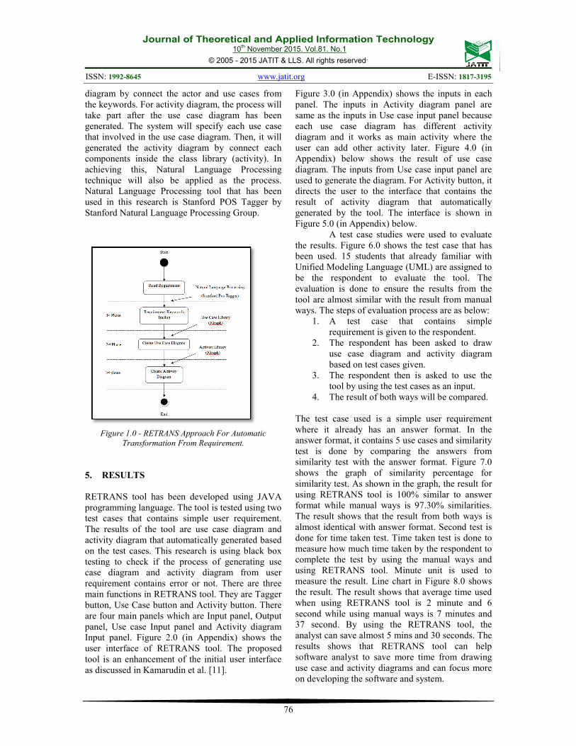
3. METHODOLOGY
In order to achieve this research objectives,
there are 3 phases need to be implemented. The
phases are: 1) Gathering and analyse information
and data involving Model Transformation and
Unified Modelling Language; 2) Modelling
RETRANS approach to automatically transform the
requirement into behaviour model using Unified
Approach (UA); 3) Develop and evaluate the
RETRANS tool. First phases focused more on
understanding the area related with the objectives
of this research. This phases are done to understand
clearly what are the components and information
regarding Model Transformation and UML. Second
phase in this research is to create and produce
model for the propose approach to automatically
transform the requirement into behaviour model
using Unified Approach. Unified Approach
establishes a unifying and unitary framework
around their works by utilizing the Unified
Modelling Language (UML) to describe, model,
and document the software development process
[8]. Last phases is to develop and evaluate
RETRANS tool. The process of development and
evaluation will be repeated until the tool is showing
the correctness or almost identical output as in
manual UML drawing process and time taken to
complete the process of generate use case diagram
and activity diagram.
4. REQUIREMENT TRANSFORMATION
INTO BEHAVIOR (USE CASE DIAGRAM
AND ACTIVITY DIAGRAM) APPROACH
In this research, we propose new approach
to transform user requirement into behavior
diagrams (use case diagram and activity diagram)
called RETRANS. RETRANS stands for
REquirement TRANSformation approach.
RETRANS is divided into 3 phases. First Phase is
Requirement phase; second phase is Use Case
Diagram generation and lastly Activity Diagram
generation. The approach is as in figure 1.0 below.
The approach is called RETRANS that stands for
Requirement Transformation. RETRANS approach
plays an important role in tool development of this
research. In this research, Java library are used to
generate each output. For use case diagram library,
the components are actor and use case. Use case
class library will be used after the detection of the
keywords from the requirement. The keyword will
first detect the actor and use cases for the
requirement, and the library will generated the
Journal of Theoretical and Applied Information Technology 10
th November 2015. Vol.81. No.1
© 2005 - 2015 JATIT & LLS. All rights reserved.
ISSN: 1992-8645 www.jatit.org E-ISSN: 1817-3195
76
diagram by connect the actor and use cases from
the keywords. For activity diagram, the process will
take part after the use case diagram has been
generated. The system will specify each use case
that involved in the use case diagram. Then, it will
generated the activity diagram by connect each
components inside the class library (activity). In
achieving this, Natural Language Processing
technique will also be applied as the process.
Natural Language Processing tool that has been
used in this research is Stanford POS Tagger by
Stanford Natural Language Processing Group.
Figure 1.0 - RETRANS Approach For Automatic
Transformation From Requirement.
5. RESULTS
RETRANS tool has been developed using JAVA
programming language. The tool is tested using two
test cases that contains simple user requirement.
The results of the tool are use case diagram and
activity diagram that automatically generated based
on the test cases. This research is using black box
testing to check if the process of generating use
case diagram and activity diagram from user
requirement contains error or not. There are three
main functions in RETRANS tool. They are Tagger
button, Use Case button and Activity button. There
are four main panels which are Input panel, Output
panel, Use case Input panel and Activity diagram
Input panel. Figure 2.0 (in Appendix) shows the
user interface of RETRANS tool. The proposed
tool is an enhancement of the initial user interface
as discussed in Kamarudin et al. [11].
Figure 3.0 (in Appendix) shows the inputs in each
panel. The inputs in Activity diagram panel are
same as the inputs in Use case input panel because
each use case diagram has different activity
diagram and it works as main activity where the
user can add other activity later. Figure 4.0 (in
Appendix) below shows the result of use case
diagram. The inputs from Use case input panel are
used to generate the diagram. For Activity button, it
directs the user to the interface that contains the
result of activity diagram that automatically
generated by the tool. The interface is shown in
Figure 5.0 (in Appendix) below.
A test case studies were used to evaluate
the results. Figure 6.0 shows the test case that has
been used. 15 students that already familiar with
Unified Modeling Language (UML) are assigned to
be the respondent to evaluate the tool. The
evaluation is done to ensure the results from the
tool are almost similar with the result from manual
ways. The steps of evaluation process are as below:
1. A test case that contains simple
requirement is given to the respondent.
2. The respondent has been asked to draw
use case diagram and activity diagram
based on test cases given.
3. The respondent then is asked to use the
tool by using the test cases as an input.
4. The result of both ways will be compared.
The test case used is a simple user requirement
where it already has an answer format. In the
answer format, it contains 5 use cases and similarity
test is done by comparing the answers from
similarity test with the answer format. Figure 7.0
shows the graph of similarity percentage for
similarity test. As shown in the graph, the result for
using RETRANS tool is 100% similar to answer
format while manual ways is 97.30% similarities.
The result shows that the result from both ways is
almost identical with answer format. Second test is
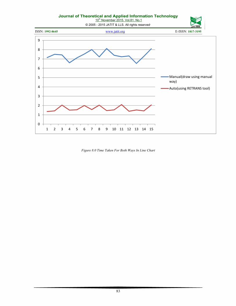
done for time taken test. Time taken test is done to
measure how much time taken by the respondent to
complete the test by using the manual ways and
using RETRANS tool. Minute unit is used to
measure the result. Line chart in Figure 8.0 shows
the result. The result shows that average time used
when using RETRANS tool is 2 minute and 6
second while using manual ways is 7 minutes and
37 second. By using the RETRANS tool, the
analyst can save almost 5 mins and 30 seconds. The
results shows that RETRANS tool can help
software analyst to save more time from drawing
use case and activity diagrams and can focus more
on developing the software and system.

Journal of Theoretical and Applied Information Technology 10
th November 2015. Vol.81. No.1
© 2005 - 2015 JATIT & LLS. All rights reserved.
ISSN: 1992-8645 www.jatit.org E-ISSN: 1817-3195
77
6. CONCLUSION
In this paper, we present about our proposed
approach in transforming the requirement into
UML diagram (use case and activity diagrams). We
have also developed and evaluated our RETRANS
tool that used to prove our proposed approach. An
experiment has been done to compare between
using RETRANS tool and by using manual ways to
find similarities percentage and time taken for both
ways. The result shows that, by using RETRANS
tool, the result is almost 100% similar with
answering format and average time taken by using
RETRANS tool is 2 minute and 6 second, almost 6
minutes faster than using manual ways. The
approach will help software developer reducing
their time in design process. This tool can be used
to generate use case diagram and activity diagram
by students who just learn about use case diagram
and activity diagram, as a comparison with
diagrams done by them. This tool also can help
software analyst to save more time from drawing
use case and activity diagrams and can focus more
on developing the software and system.
REFERENCES:
[1] Afreen, H., Bajwa, I.S.,and Bordbar, B., 2011,
SBVR2UML: A Challenging Transformation,
Proc. Of the 2011 Frontiers of Information
Technology, pp. 33-38.
[2] Barrera D., 2011,Communicating Systems
with UML 2: Modeling and Analysis of
Network Protocols. ISTE and John Wiley &
Sons.
[3] Brian D. and Jefrrey P., May 2006 ,How UML
is used, Magazine Communications of the
ACM - Two decades of the language- action
perspective CACM Volume 49 Issue 5,
Pages 109-113
[4] Enrico Biermann, Kartsten Ehrig, Christian
Kohler, Gunter Kuhns,Gabriele Taentzer and
Eduard Weiss, 2006, Graphical Definition of
In-Place Transformations in the Eclipse
Modeling Framework, Model Driven
Engineering Languages and Systems Lecture
Notes in Computer Science, Volume 4199, pp
425- 439.
[5] Fahad A., and Nazir A. Z., 2014, Possible
Improvements in UML Behavior Diagrams,
2014 International Conference on
Computational Science and Computational
Intelligence.
[6] Fanchao M., Dianhui C., and Dechen Z., Dec
2010, Transformation from Data Flow
Diagram to UML2.0 activity diagram,
Progress in Informatics and Computing (PIC),
2010 IEEE International Conference
on (Volume:2 ).
[7] Gobinda G. Chowdhury, 2003, Natural
Language Processing, Annual Review of
Information Science and Technology,Volume
37, Issue 1, pages 51-89.
[8] James R., Michael B., William P., Frederick
E., and William L., 2004, Object Oriented
Modeling and Design, General Electric
Research and Development Center
Schenectady,New York.
[9] Jayeeta C., Ananya K.,Sabnam S., and
Swapan B., 2009, Traceability of
Requirements and Consistency Verification of
UML UseCase, Activity and Class diagram: A
Formal approach , Methods and Models in
Computer Science, 2009. ICM2CS 2009.
Proceeding of International Conference on.
[10] Jim Barnett, Kevin Knight, Inderjeet Mani,
and Elaine Rich, 1990, Knowledge and natural
language processing, Magazine
Communications of the ACM Volume 33
Issue 8,Page 50-71.
[11] Kamarudin, N.J., Sani, N.F.M. and Atan, R.,
2013, New Model Transformation using
Requirement Traceability from Requirement
to UML Behavioral Design, Journal of
Theoretical and Applied Information
Technology, Vol. 49, No. 3, pp. 889-895.
[12] Kleppe A.G, Jos W., Wim B., 2003, MDA
Explained: The Model Driven Architecture:
Practice and Promise, Addison-Wesley
Longman Publishing Co., Inc. Boston, MA,
USA ©2003 ISBN:032119442X.
[13] Li Jin and Yin Guisheng, 2010, Method of
constructing model transformation rule based
on reusable pattern, International Conference
on Computer Application and System
Modelling (ICCASM), Volume 8.
[14] Marcos D.D.F and Patrick V., 2007, Semi-
automatic Model Integration using Matching
Transformations and Weaving Models , SAC

Journal of Theoretical and Applied Information Technology 10
th November 2015. Vol.81. No.1
© 2005 - 2015 JATIT & LLS. All rights reserved.
ISSN: 1992-8645 www.jatit.org E-ISSN: 1817-3195
78
'07 Proceedings of the 2007 ACM symposium
on Applied computing.
[15] Marcos Didonet Del Fabro and Patrick
Valduriez, July 2009, Towards the efficient
development of model transformations using
model weaving and matching transformations,
Software & Systems Modeling ,Volume
8,Issue 3, pp 305-324,
[16] Riaz. S.S.A., 2009, Review and Analysis of
the issues on Unified Modeling Language for
Visualizing, Specifying, Constructing and
Documenting the Artifacts of a Software
Intensive System, International Journal of
Engineering Science and Technology Vol
.1(3), 100-118.
[17] Tao Y., Lionel C.B., and Yvan L., June 2010,
An Automated Approach to Transform Use
Cases into Activity Diagrams, 6th European
Conference, ECMFA 2010 Proceedings.
[18] Dániel Varró, Márk Asztalos, Dénes
Bisztray, Artur Boronat, Duc-Hanh
Dang, Rubino Geiß, Joel Greenyer, Pieter
Van Gorp,Ole Kniemeyer, Anantha
Narayanan, Edgars Rencis and Erhard
Weinell, 2008, Transformation of UML
Models to CSP: A Case Study for Graph
Transformations Tools, Applications of Graph
Transformations with Industrial Relevance
Lecture Notes in Computer Science Volume
5088, pp 540- 565.
[19] Wimmer M., Strommer M., Kargl H., and
Kramler G., 2007, Towards Model
Transformation Generation By-Example, 40th
Annual Hawaii International Conference on
System Sciences.
[20] Zhuoyan C., 2011, The research of software
development supporting environment based
on UML, Electronic and Mechanical
Engineering and Information Technology
(EMEIT), 2011 International Conference
on (Volume:1 ).

Journal of Theoretical and Applied Information Technology 10
th November 2015. Vol.81. No.1
© 2005 - 2015 JATIT & LLS. All rights reserved.
ISSN: 1992-8645 www.jatit.org E-ISSN: 1817-3195
79
APPENDIX
Figure 2.0 - User Interface For RETRANS Tool

Journal of Theoretical and Applied Information Technology 10
th November 2015. Vol.81. No.1
© 2005 - 2015 JATIT & LLS. All rights reserved.
ISSN: 1992-8645 www.jatit.org E-ISSN: 1817-3195
80
Figure 3.0 - Inputs In 4 Different Panels

Journal of Theoretical and Applied Information Technology 10
th November 2015. Vol.81. No.1
© 2005 - 2015 JATIT & LLS. All rights reserved.
ISSN: 1992-8645 www.jatit.org E-ISSN: 1817-3195
81
Figure 4.0 - Result Of Use Case Diagram Generated From RETRANS Tool
Figure 5.0- Result Of Activity Diagram Generated From RETRANS Tool

Journal of Theoretical and Applied Information Technology 10
th November 2015. Vol.81. No.1
© 2005 - 2015 JATIT & LLS. All rights reserved.
ISSN: 1992-8645 www.jatit.org E-ISSN: 1817-3195
82
Figure 6.0 Test Cases
Figure 7.0 Similarity Percentages For Similarity Test
97.30% 100%
Manual(draw using
manual way)
Auto (using RETRANS
tool)
Journal of Theoretical and Applied Information Technology 10
th November 2015. Vol.81. No.1
© 2005 - 2015 JATIT & LLS. All rights reserved.
ISSN: 1992-8645 www.jatit.org E-ISSN: 1817-3195
83
Figure 8.0 Time Taken For Both Ways In Line Chart
0
1
2
3
4
5
6
7
8
9
1 2 3 4 5 6 7 8 9 10 11 12 13 14 15
Manual(draw using manual
way)
Auto(using RETRANS tool)