ISSN 2348 – 7968 Photonic Crystal Fiber Bragg grating...
10
IJISET - International Journal of Innovative Science, Engineering & Technology, Vol. 2 Issue 3, March 2015. www.ijiset.com ISSN 2348 – 7968 Photonic Crystal Fiber Bragg grating Using Olive Oil as Liquid Photonic Crystal and Adhesive Material for Construction Anmar Engad 1 , Hisham Mohammed Ahmed 2 and Anwaar A. Al- Dergazly 3 Laser and optoelectronics engineering, Nahrain University , College of engineering Baghdad, Jadria, Iraq 2 Laser and optoelectronics engineering, University of Technology, Baghdad, 62 street, Iraq 3 Laser and optoelectronics engineering, Nahrain University , College of engineering Baghdad, Jadria, Iraq Abstract In this project study the properties and the ability of optical adhesive material to function as Bragg grating. Fiber Bragg grating using photonic crystal fiber filled with mixture of olive oil and optical adhesive was design and construct. Diode laser 405 nmr used to writ on fiber. The experimental setup of Dual-Beam Holographic Technique was used to fabricate Fiber Bragg grating with Bragg reflection wavelength (λ B ) of 806 nm. Keywords: fiber Brag grating, olive oil, photonic crystal fiber, optical adhesive. 1. Introduction The Bragg diffraction occurs for an electromagnetic radiation whose wavelength is the same order of magnitude of atomic spacing when it is incident upon a crystalline material. In this case, the radiation is scattered in a specular fashion by the atoms of the material and experiences constructive interference in accordance to Bragg's law. For a crystalline solid with lattice planes separated by distance d, the waves are scattered and interfere constructively if the path length of each wave is equal to an integer multiple of the wavelength. Bragg's law describes the condition for constructive interference from several crystallographic planes of crystalline lattice separated by distance d : ………(1) Where θ is the incident angle, n is an integer and λ is the wavelength. A diffraction pattern is obtained by measuring the intensity of scattered as a function of angle θ. wherever the scattered waves satisfy the Bragg condition, it is observed a strong intensity in the diffraction pattern, known as Bragg peak [1]. Bragg grating is reflecting structures with a periodic refractive index modulation. An optical Bragg grating is a transparent device with a periodic variation of the refractive index, so that a large reflectivity may be reached in some wavelength range (bandwidth) around a certain wavelength which fulfills the Bragg condition …………. (2) Where λ is the vacuum wavelength of light, n the refractive index, θ the propagation angle in the medium relative to the direction normal to the grating, and Λ is the grating period. If this condition is satisfied, the wavenumber of grating matches the diffraction of the wavenumbers of the incident and reflected waves. Other wavelengths are only weakly affected by the Bragg grating, except for some side lobes in the reflection spectrum. 2. Fiber Bragg grating Fiber Bragg grating is a periodic variation of refractive index along the length of an optical fiber and it is produced due to photosensitivity of optical fiber by exposing of the core to a periodic pattern of intense optical interference light [2] . It reflect narrow wavelength range of light and transmits all other wavelengths. Schematic diagram of a fiber Bragg grating as shown in figure 1. The fringes of optical interference pattern will create a permanent refractive index change with amplitude Δn and pitch Λ that extends over a length L of the fiber . The refractive index change along the region of a fiber Bragg grating can be divided into a DC offset (mean amplitude) and an AC port (sinusoidal variation) as shown in figure 2 224
Transcript of ISSN 2348 – 7968 Photonic Crystal Fiber Bragg grating...

IJISET - International Journal of Innovative Science, Engineering & Technology, Vol. 2 Issue 3, March 2015.
www.ijiset.com
ISSN 2348 – 7968
Photonic Crystal Fiber Bragg grating Using Olive Oil as Liquid Photonic Crystal and Adhesive Material for Construction
Anmar Engad1, Hisham Mohammed Ahmed 2 and Anwaar A. Al- Dergazly3
Laser and optoelectronics engineering, Nahrain University , College of engineering
Baghdad, Jadria, Iraq
2 Laser and optoelectronics engineering, University of Technology, Baghdad, 62 street, Iraq
3 Laser and optoelectronics engineering, Nahrain University , College of engineering
Baghdad, Jadria, Iraq
Abstract
In this project study the properties and the ability of optical adhesive material to function as Bragg grating. Fiber Bragg grating using photonic crystal fiber filled with mixture of olive oil and optical adhesive was design and construct. Diode laser 405 nmr used to writ on fiber. The experimental setup of Dual-Beam Holographic Technique was used to fabricate Fiber Bragg grating with Bragg reflection wavelength (λB) of 806 nm. Keywords: fiber Brag grating, olive oil, photonic crystal fiber, optical adhesive.
1. Introduction
The Bragg diffraction occurs for an electromagnetic radiation whose wavelength is the same order of magnitude of atomic spacing when it is incident upon a crystalline material. In this case, the radiation is scattered in a specular fashion by the atoms of the material and experiences constructive interference in accordance to Bragg's law. For a crystalline solid with lattice planes separated by distance d, the waves are scattered and interfere constructively if the path length of each wave is equal to an integer multiple of the wavelength. Bragg's law describes the condition for constructive interference from several crystallographic planes of crystalline lattice separated by distance d :
………(1) Where θ is the incident angle, n is an integer and λ is the wavelength. A diffraction pattern is obtained by measuring the intensity of scattered as a function of angle θ. wherever the scattered waves satisfy the Bragg condition, it is observed a strong intensity in the diffraction pattern, known as Bragg peak [1].
Bragg grating is reflecting structures with a periodic refractive index modulation. An optical Bragg grating is a transparent device with a periodic variation of the refractive index, so that a large reflectivity may be reached in some wavelength range (bandwidth) around a certain wavelength which fulfills the Bragg condition
…………. (2) Where λ is the vacuum wavelength of light, n the refractive index, θ the propagation angle in the medium relative to the direction normal to the grating, and Λ is the grating period. If this condition is satisfied, the wavenumber of grating matches the diffraction of the wavenumbers of the incident and reflected waves. Other wavelengths are only weakly affected by the Bragg grating, except for some side lobes in the reflection spectrum. 2. Fiber Bragg grating Fiber Bragg grating is a periodic variation of refractive index along the length of an optical fiber and it is produced due to photosensitivity of optical fiber by exposing of the core to a periodic pattern of intense optical interference light [2] . It reflect narrow wavelength range of light and transmits all other wavelengths. Schematic diagram of a fiber Bragg grating as shown in figure 1. The fringes of optical interference pattern will create a permanent refractive index change with amplitude Δn and pitch Λ that extends over a length L of the fiber . The refractive index change along the region of a fiber Bragg grating can be divided into a DC offset (mean amplitude) and an AC port (sinusoidal variation) as shown in figure 2
224

IJISET - International Journal of Innovative Science, Engineering & Technology, Vol. 2 Issue 3, March 2015.
www.ijiset.com
ISSN 2348 – 7968
Figure 1 Schematic diagram of a fiber Bragg grating [2]
Figure 2 Refractive index variation of a fiber Bragg grating
Optical waves propagated inside along the fiber are unaffected by the grating, but for a specific wavelength such a periodic structure acts as a Bragg reflector with a pronounced reflectivity .This wave length ,the so called the Bragg wavelength λB [3] which is defined as:
λB =2 neff Λ (1) where the neff is the effective refractive index and Λ is the Bragg grating period . For a uniform Bragg grating formed within the core of an optical fiber The coupled mode theory and Transfer matrix method are used to analysis the reflection spectra of fiber Bragg grating [4]. So the reflectivity of a grating with uniform index modulation and period is given by following equation [5]:
R= (2)
Where R is the grating reflectivity as a function of both grating length and wavelength. L is the total length of Bragg grating. κ is the coupling coefficient and it is defined by the following equation:
κ = (3) where Δn is the refractive index change. at the uniform fiber Bragg grating, then =1, the fringe visibility and is usually estimated at 1.
Δβ is the wave vector detuning and it is given by Δβ =β-π/Λ and β is the propagation constant and is given by β=2πno/λ ,finally γ At the center wavelength of the Bragg grating the wave vector detuning is Δβ=0 and the reflectivity becomes:
R= (4)
3. Photosensitivity The expression photosensitivity in context of writing waveguide or Bragg gratings in optical materials is used to describe the produced change of the optical properties due to expose to radiation. Adhesives system which use UV light from 315nm to 400nm or visible light from 400nm to 460nm to begin curing are very attractive system to the manufacturing engineer, allowing assembly of components and then curing on command by exposing to the UV irradiation [8]. UV cured systems are based on an addition cure polymerization where by a free radical or cationic adds to a carbon-carbon double bond or an oxirane ring and a chain reaction leads to formation of a polymer. The combination of multifunctional and monofunctional monomers gives rise to crosslinking reaction, which contribute strength and heat resistance to the formulations. In the case of adding photoinitiators compounds, the UV- radiation curing consist of a photoinitiated polymerization of multi-functional monomers which are converted into a tridimensional polymer network according to the following reaction scheme :
A photoinitiator is used to absorb the UV-radiation and generate upon cleavage the reactive species, free radical or protonic acid, that will initiate the cross linking polymerization reaction according to a radical or cationic mechanism, respectively [10]. The types of UV-radiation curing adhesives are Norland Optical Adhesives type NOA 68,NOA 72 ,Poly-Lite windshield resin type CF-thin, DYMAX and Glassmechanix type star line which they are used for glass to glass bonding. These polymers can be used for producing crystal Bragg grating by adding two different
225

IJISET - International Journal of Innovative Science, Engineering & Technology, Vol. 2 Issue 3, March 2015.
www.ijiset.com
ISSN 2348 – 7968
materials in different quantities such as liquid crystal mixed with polymer adhesive.
4. Fabrication Techniques This section discusses briefly four major techniques, used commonly for making Bragg gratings and known as the single-beam internal technique, the dual-beam holographic technique, the phase-mask technique, and point-by-point technique. The dual-beam holographic technique, shown schematically in Figure 3,it is also known as the Bulk Interferometer technique [14].
Figure 3 Schematic illustration of the dual-beam holographic technique
[15]. An external interferometric scheme similar to that used for holography is used [7]. It utilized an interferometer that split the incoming UV light into two optical beams and then recombined them to form an interference pattern. The fringe pattern was used to expose a photosensitive fiber, inducing a refractive index modulation in the core. Bragg gratings in optical fibers have been fabrication using both amplititude splitting and wave-front- splitting interferometers [6]. The Bragg grating period Λ which is identical to the period of the interference fringe pattern, depends on both the irradiation wavelength is λw and the half-angle between the two interfering UV beams, φ through the simple relation [16]
(5) The interference pattern is formed in glass (within the core of the optical fiber), its period is the same as it would be if the beams were interfering in air [6].
Given the Bragg condition, λB =2neffΛ , the Bragg grating resonance wavelength can be represented in terms of the UV writing wavelength and the half- angle between two interfering UV beams as
λB= (6) Where λB is the Bragg reflection wavelength and neff is the effective core index, from Eq.(5) the Bragg grating period Λ can be varied either by changing λB and/or φ. The choice of λw is limited to the photosensitivity region of the fiber [16].
5. Bragg Materials preparation
One of the most important steps which used in this project is the light effect on the polymer adhesive photosensitive material causing chemical reaction where the polymer adhesive cure process depend on the intensity and the wavelength of the light radiation . This reaction leads to change in physical properties of the material including the refractive index. As mentioned before, the Bragg grating depends mainly on the change in refractive index.
Glass Mechanix star line adhesive is a low viscosity adhesive for bonding glass and it is a clear, colorless, liquid photopolymer adhesive that will cure when exposed to ultraviolet light.
The absorption spectrum of Glass Mechanix star line adhesive obtained from ultraviolet-Visible spectrophotometer is shown in figure 4.
Figure 4 the Absorption spectrum of Glass Mechanix star line adhesive The curve shows that the Glass Mechanix star line adhesive material has absorption range between maximum absorption at 385nm. This means that at such wavelength the fastest curing process occurs. As we move further from 385nm, the curing process requires more time depending on the absorption percentage. As a matter of fact, there is
226

IJISET - International Journal of Innovative Science, Engineering & Technology, Vol. 2 Issue 3, March 2015.
www.ijiset.com
ISSN 2348 – 7968
no laser source available at such wavelength. Therefore, the closest suitable laser source is used and it was at 405nm. Looking back at the curve, the material has absorption of 10% at such wavelength making it optically usable for this research but it requires more time to treatment Olive Oil which classified as organic compound, having a good nonlinear optical properties candidate to be used in photonics applications, was used as liquid crystal. The optical transmission measurement of olive oil was analyzed using UV-VIS spectrophotometer. Figure 5 shows the transmission spectrum of olive oil.
Figure 5: UV-VIS transmission spectrum of olive oil. In order to find the most suitable material for Bragg fabrication, the Glass Mechanix star line adhesive material is tested optically. The testing operation includes forming a grating period using the setup shown in figure (6)
Fdfdf
Figure 6 Sample testing setup
The setup consists of three main parts. A laser source, phase mask, and the sample. The laser used in this project is 405nm.
Two phase masks are used in the setup. The first one by using transmission diffraction grating is an optical component having a periodic structure which diffracts and splits light into several beams. The grating is
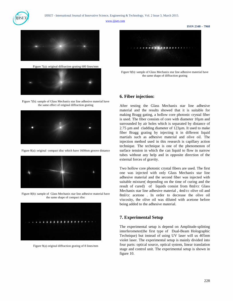
made from many parallel slits ,all with same width and equally spaced distance. The grating is positioned on the surface of a flat piece of transparent material. Where the slits are opaque, the areas between the slits can transmit light. The number of slit can be from 4 lines per millimeter to 1200 lines per millimeter. In this testing experiment, the two transmission diffraction gratings which used are of 8 lines per millimeter and 600 lines per millimeter respectively. In other words, the distance between two slits for 8 lines per millimeter is 125000nm and for 600 lines per millimeter is 1666.67nm. The second phase mask is done by using compact disc (CD) which is an optical digital data storage. The CD consists of three layers : the first one is transmitted layer made from plastic polycarbonate substrate ,which has a spiral pre-groove track. The grooves used to help the writing laser to stay and write the data on the track. the track width is 400 to 500 nm and the track pitch (the distance between two track ) is 1600nm. The second layer is a metalized layer, which coat the data layer and provide the reflectivity. Finally, the third layer is a lacquer protective layer. After removing the reflective layer of the compact disc (the metalized layer and the protective layer) with tape ,it is became transparent and can be used as phase mask as well as the transmission diffraction grating. the laser beam can easily pass through between the Nano groove track of the compact disc (CD) or the Nano slit of transmission diffraction grating making the fringes pattern. These fringes projected on the sample producing longitudinal periodic variation in refractive index inside the sample and record the same shape, in size and distance, of slit or groove on the adhesive material. The sample consists of the adhesive material layer sandwiched between two glass slides. The glass must be bond firmly in order to hold the adhesive liquid in place. After leaving the sample exposed to the laser beam through the phase mask for a certain time, the sample is removed for further testing. In the next step, the sample is placed in front of the laser beam only. A good sample displays clear visible fringes. The result prove that the glass matrix adhesive can be used in FBG fabrication process. The result is shown in figures( 7-9).
Glass
Sample
Laser
Phase mask
Glass
Adhesive Material
227
IJISET - International Journal of Innovative Science, Engineering & Technology, Vol. 2 Issue 3, March 2015.
www.ijiset.com
ISSN 2348 – 7968
Figure 7(a): original diffraction grating 600 lines/mm
Figure 7(b): sample of Glass Mechanix star line adhesive material have the same effect of original diffraction grating
Figure 8(a): original compact disc which have 1600nm groove distance
Figure 8(b): sample of Glass Mechanix star line adhesive material have the same shape of compact disc
Figure 9(a) original diffraction grating of 8 lines/mm
Figure 9(b): sample of Glass Mechanix star line adhesive material have the same shape of diffraction grating
6. Fiber injection: After testing the Glass Mechanix star line adhesive material and the results showed that it is suitable for making Bragg gating, a hollow core photonic crystal fiber is used. The fiber consists of core with diameter 10µm and surrounded by air holes which is separated by distance of 2.75 µm and cladding diameter of 123µm. It used to make fiber Bragg grating by injecting it in different liquid martials such as adhesive material and olive oil. The injection method used in this research is capillary action technique. The technique is one of the phenomenon of surface tension in which the can liquid to flow in narrow tubes without any help and in opposite direction of the external forces of gravity. Two hollow core photonic crystal fibers are used. The first one was injected with only Glass Mechanix star line adhesive material and the second fiber was injected with suitable mixture( depending on the time of curing and the result of cured) of liquids consist from 8ml/cc Glass Mechanix star line adhesive material , 4ml/cc olive oil and 8ml/cc acetone . In order to decrease the olive oil viscosity, the olive oil was diluted with acetone before being added to the adhesive material.
7. Experimental Setup The experimental setup is depend on Amplitude-splitting interferometer(the first type of Dual-Beam Holographic Technique) but instead of using UV laser will us 405nm violet laser. The experimental setup is mainly divided into four parts: optical source, optical system, linear translation stage and control unit. The experimental setup is shown in figure 10.
228

IJISET - International Journal of Innovative Science, Engineering & Technology, Vol. 2 Issue 3, March 2015.
www.ijiset.com
ISSN 2348 – 7968
Figure 10 The experimental setup for fiber Bragg grating fabrication
The optical source is a CW laser diode (SDL-405-100T) operated at wavelength 405 nm with output optical power 100mW and it is switched on/off by control unit. The reason of choosing this wavelength is that it matches the absorption spectrum of the adhesive material which was injected in hollow core photonic crystal fiber. As usual, the beam profile of the laser diode used shows the elliptical divergence shape with high divergence angle. Therefore, it is required to be reshaped in order to fit beam shape into circular profile.
The optical system consists of three parts: a Beam splitter, two pinholes and two mirrors. Each one has a special significance to fabricate fiber Bragg grating as shown in figure (11).
Figure 11 optical setup The laser beam passes through the beam splitter,
where it is separated into two beams of equal in power. A plate beam splitter was used in this experiment as shown in figure (4.5) and it was optimized for an incidence angle of 45 degree to split the beam R/T= 50/50 and suitable for the wavelength of 405nm.The front surface of the beam splitter is coated with dielectric material while the back surface is coated with antireflection material in order to
reduce the possibility of ghost images effects caused by the interference light reflected from the front and back surfaces of the beam splitter. The beam profile of the laser diode is required to be circular and of minimized bandwidth in order to fit the hollow core photonic crystal fiber size and determine writing pattern size onto cross section area of the PCF fiber. Another advantage of shaping the beam is to increase the number of areas that are exposed to laser radiation which allows the possibility of creating a large number of highly precise grating periods. So, each separated beam of the laser diode was shaped from elliptical profile to circular profile by using pinhole with small circular aperture. The bandwidth ( full width half maximum ) of each laser beam was proximately 171 µm for each axis after being 2896 µm for y-axis and 967 µm for x-axis before the shaping process. The beam shape before and after the shaping is shown in figure 12
Figure 12 (a) Beam profile of laser diode (b) Beam profile of laser diode . without using pinhole after using pinhole
Then the two laser beams were reflected by using two dielectric mirrors where each mirror had the ability to control the direction of each beam by moving the mirror in x and in y axes. After that, the two laser beams were combined and directed making interference pattern into the core of the photosensitive PCF fiber as shown in figure 13.
Figure 13 The two laser beams are make the interference pattern
Linear translation stage is a one direction stage that is moving in z axis as shown in figure 14.
229

IJISET - International Journal of Innovative Science, Engineering & Technology, Vol. 2 Issue 3, March 2015.
www.ijiset.com
ISSN 2348 – 7968
Figure 14 Linear translation stage The hollow core photonic crystal fiber was installed on the stage and held by using fiber clamps separated by a distance of 5cm. The motor was used in the stage is a bipolar stepper motor with 20 steps per rotation. The lead screw of the motor has 3mm moving pitch giving it a resolution of 150µm for each step of stepper motor. The total moveable distance of the stage is 5cm in one direction.
8. Output detection and data recording It is important to record the output wavelength from the PCF fiber to ensure if the writing process of fiber Bragg grating is done correctly, and to determine the value of Bragg reflection wavelength. A multimode optical fiber end of 250 µm aperture size is aligned near to the PCF fiber sample. The other end of the fiber is connected to the spectrometer for data analysis and recording. The portion of the light that enters the fiber is related to near field measurements only. The setup which is used for testing the fabricated fiber Bragg grating is shown in figure 15.
Figure 15 Testing fiber Bragg grating setup The setup consists of a metric ruler, 808nm laser source, collimating lens, focusing lens, fiber clamp, PCF-MMF coupler, and spectrometer. Each device has its own function in this setup. The optical rail is used to hold the
other parts tightly in place. It also helps to align the testing parts. The 808nm laser source is used for testing the functionality of the fiber. However, the light emitted from this source is not collimated or focused. Therefore, a collimating lens and a focusing lens is used to focus the beam at the end of the PCF fiber. The fiber clamp is used to hold the fiber firmly in place. The PCF-MMF coupler is used to couple the light from the FBG fiber to the MMF fiber. The MMF fiber then carries the resulted light to the spectrometer for further analysis. The spectrometer is a fast wavelength scanning device that can record the detected power for each wavelength. It has internal CCD line array with 3648 pixel. It is also auto compensated for dark current noise and amplitude corrected. This detector is sensitive to wavelengths from 200 nm to 1000 nm. Various parameters can be changed for optimizing the detected power. The spectrometer is used for detecting the power of the desired wavelength before and after FBG fabrication. The extreme sensitivity of the device provides accurate data for sensing the effect of the Braggs. When the fabricated Braggs filter wanted wavelength, the spectrometer displays the exact amount of power that’s transmitted from these Braggs so the reflected wavelength can be determined. The experimental setup of Dual-Beam Holographic Technique was used to fabricate Fiber Bragg grating with bragg reflection wavelength (λB) of 806 nm. The value of half- angle between two interfering violet (405nm) laser beams (φ) depends on the Bragg reflection wavelength (λB) and is theoretically calculated by applying equation (6). So, the value of half-angle between two interfering violet (405nm) laser beams has to be 47.1 degrees. The first step after every fabrication process is to inspect the sample visually. This is mostly done by using an optical microscope. The microscope images reveal various important information about the properties of the sample. The optical analysis shows if the fabrication process is done successfully. Moreover, it shows the defects that may occur during the fabrication process.The Bragg grating appear in the core of the fiber for two fibers. The first fiber made from Glass Mechanix star line adhesive and the second fiber made from liquid mixture (Glass Mechanix star line adhesive material, olive and acetone). The 2nd sample used in this thesis is fabricated using a mixture of Glass Mechanix star line adhesive material (20ml), olive (10ml) and acetone (10ml).. In other words, the areas that are cured by laser spot are hardly recognized. This shows that the addition of acetone and olive oil decrease the effect of laser spot. Hence, the curing process time increased.
230

IJISET - International Journal of Innovative Science, Engineering & Technology, Vol. 2 Issue 3, March 2015.
www.ijiset.com
ISSN 2348 – 7968
The fiber made from Glass Mechanix star line adhesive show clear grating period than the fiber made from liquid mixture because the photosensitive material is higher in the first fiber. The optical characterization is the process that show the band of wavelength in which the sample’s operation is tested whether it functions properly. This characterization process is done by passing the specific laser through the sample. In this project, a 808nm laser is used for the testing process. Figure 16 shows the output spectrum of a hollow core fiber without grating fabrication. It can be seen that the laser passes through the fiber without any alteration on the laser spectrum. i.e. no reflection occurs at the laser peak 806nm. This result is useful for comparing this output spectrum with the FBG fabricated samples.
Figure 16 Spectrum of 808nm laser diode after passing the hollow core
fiber without any injected material
8.1 Glass Mechanix star line Fiber Bragg Grating The fiber bragg grating which is fabricated using Glass Mechanix star line adhesive material is tested using the same process mentioned above. The output spectrum of the sample is shown in figure 17. The fabricated Bragg grating length is 4.5cm. It can be noted from the output that the laser peak decreases at 806nm. This reduction is due to the reflection from the alternating layers of the bragg grating in the core of the fiber and then is no absorption. The reflection at 806nm matches the calculated Bragg wavelength of the Glass Mechanix star line adhesive material. As mentioned before, the refractive indices and the layer thicknesses determine the reflection wavelength. So, by altering the thickness, the peak bragg wavelength can be blueshifted or redshifted. However, the thickness is determined by the interference occurred from the two beam generated by the laser used in the fabrication.
The quality of the bragg is determined by the sharpness or the width of the bragg wavelength. The smaller linewidth means the precise reflection occurs at the desired wavelength. Figure 17 shows a sharp drop at 806nm expressing a high precision reflection process.
Figure 17 The output spectrum of Fiber Bragg Grating made from Glass
Mechanix star line adhesive 8.2 Glass Mechanix star line and Olive oil Fiber Bragg Grating: The second examination involves the test of the fiber bragg grating with the bragg made from a mixture Glass Mechanix star line, Olive oil, and Acetone. The results in figurer 18 show that a slight reflection at 806nm with less sharpness than the first sample. This indicates that there is weak reflection from the alternating Bragg layers. This weakness comes from the fact that the mixture is weakly cured when the fiber core exposed to the laser spot.
Figure 18 The output spectrum of Fiber Bragg Grating made from liquid mixture (Glass Mechanix star line adhesive material, olive and acetone)
8.3 The differences between the graphs of out put spectrum From comparing both fiber bragg grating samples, using the glass mechanix star line alone as bragg material gives a better spectrum output, producing a sharper output with more reflection depth. Thus, decreasing the length of the fiber required for the fabrication process and decreasing the cost. In other words, to obtain the same results from the Glass Mechanix star line, Olive oil, and Acetone mixture, the length of the fiber has to be doubled or tripled putting a direct effect on the cost and the time of the fabrication process. Table 4-1 shows the numerical analysis of the
231

IJISET - International Journal of Innovative Science, Engineering & Technology, Vol. 2 Issue 3, March 2015.
www.ijiset.com
ISSN 2348 – 7968
spectrums by using equations in chapter 2. Noting that both samples’ bragg wavelength is the same with only 0.7 nm difference. However, the change refractive index quit varies with amount of 2 which mean the glass liquid sample layers of refractive indices n1 and n2 more different compared with liquid mixture sample . Although the liquid mixture’s (full width half maximum) linewidth is less than of the glass liquid.
Table 1: the different between two injected materials
Injected material
λB (nm) Δn neff
Glass
Mechanix star line adhesive
806.2313232
7.751864724x
10-6
1.45826911
liquid mixture
806.9509277 5.297778729x10⁻⁶
1.459571304
8.4 Testing the values of real work In order to investigate the Bragg grating further. A code simulation is done using the same parameters which is used in the fabrication process. The reflected wavelength of the simulation of glass matrix material is shown in Figure 19.
Figure 19 The reflectivity of Glass Mechanix star line adhesive
The simulation figure shows the reflection spectrum of the Bragg grating using the coupled mode theory and the transfer matrix method (TMM) by applying equation (2) . The simulation indicates the center wavelength of the reflection is 806nm matching the reflection wavelength of both fabricated samples. The effective refractive index used in the simulation is the same as shown in table 4-1 which is obtained by experimental calculations.
Figure 20 The reflectivity of liquid mixture (Glass Mechanix star line
adhesive material, olive and acetone)
Figure 20 above shows the simulation using the parameters of the mixture liquid. The results show the reflectivity is extremely low compared to the reflectivity of the glass material for the same number of layers. The reflectivity of the glass material is nearly 80% while the reflectivity of the mixture is only 50% indicating poor Bragg reflection. 9. Conclusion In this work can be conclude that:
1- Get large difference in refractive index between polymer and liquid crystal.
2- It could be select the intensity of Bragg wavelength by change the mixture of olive oil and adhesive material.
3- It could be shifted the Bragg wavelength by change the intensity of laser due to nonlinearity of olive oil.
References [1] Hill, K.O.; Fujii, Y.; Johnson, D.C.; Kawasaki, B.S.,
"Photosensitivity in optical fiber waveguides: Application to reflection filter fabrication," Applied Physics Letters , vol.32, no.10, pp.647,649, May 1978
[2] Paschotta, R., Encyclopedia of Laser Physics and Technology. 2008: John Wiley & Sons.
[3] Jülich, F. and Roths, J., "Determination of the Effective
Refractive Index of Various Single Mode Fibres for Fibre Bragg greting sensor application", Proceedings of SENSOR+TEST Conference (OPTO-2009), Nürnberg, pp 119-124, 2009.
[4] Abdallah Ikhlef, Rachida Hedara and Mohamed Chikh-bled"Uniform Fiber Bragg Grating modeling and simulation used matrix transfer method"IJCSI
232

IJISET - International Journal of Innovative Science, Engineering & Technology, Vol. 2 Issue 3, March 2015.
www.ijiset.com
ISSN 2348 – 7968
International Journal of Computer Science Issues, Vol. 9, Issue 1, No 2, January 2012.
[5] Erdogan, Turan, "Fiber grating spectra," Lightwave Technology, Journal of , vol.15, no.8, pp.1277,1294, Aug 1997.
[6] Othonos, Andreas, "Fiber Bragg gratings," Review of Scientific Instruments , vol.68, no.12, pp.4309,4341, Dec 1997.
[7] Agrawal, G., Application of Nonlinear Fiber Optics. 2010: Academic Press.
[8] Dunn, D.J., Adhesives and Sealants: Technology,
Applications and Markets. 2003: Rapra Technology Limited.
[10] Cognard, P., Handbook of Adhesives and Sealants:
General Knowledge, Application of Adhesives, New Curing Techniques. 2006: Elsevier Science.
[14] Kashyap, R., Fiber Bragg Gratings. 2009: Academic
Press. [15] Othonos, A. and K. Kalli, Fiber Bragg Gratings:
Fundamentals and Applications in Telecommunications and Sensing. 1999: Artech House.
[16] Venghaus, H., Wavelength Filters in Fibre Optics. 2010: Springer Berlin Heidelberg.
233