ISSN 2348 – 7968 Optical Orthogonal Frequency Division ...ijiset.com/v1s9/IJISET_V1_I9_56.pdf ·...
7
IJISET - International Journal of Innovative Science, Engineering & Technology, Vol. 1 Issue 9, November 2014. www.ijiset.com ISSN 2348 – 7968 Optical Orthogonal Frequency Division Multiplexing Using Interval Shift Key Subcarriers Mohammed JamalAdin1 , Amin Babikr A/Nabi Mustafa2 , Mohammed AbdAlla Adam Elmaleeh2 1 Communication and Computer Network Department, Khartoum City for Children Ability, Khartoum, Sudan 2 Communication Engineering Departments, Faculty of Engineering, Alneelain University, Khartoum, 12702, Sudan 2 Computer Engineering Department, Faculty of Engineering, Alneelain University, Khartoum, 12702, Sudan Abstract Optical wireless communication is an emerging dynamic research and development area that has generated a vast number of interesting solutions to very complicated communication challenges. The transmission power employed in optical wireless communication configurations (mainly indoors) is limited by numerous factors, including eye safety, physical device limitations and power consumption, in outdoor and free space optical systems. To overcome the attenuation due to fog, one could employ lasers with higher powers, but this is also limited by the eye safety standards. Both Quadrature amplitude modulation on discrete multitones and multilevel pulse amplitude modulation are spectrally efficient modulation schemes suitable for light emitting diode based communications, but are less power efficient. Orthogonal frequency division multiplexing (OFDM) transmission scheme is a type of multichannel systems. It does not use individual band limited filters and the oscillators for each sub-channel and furthermore, the spectra of subcarriers are overlapped for bandwidth efficiency. In this paper, a modulation scheme named interval shift key modulation is implemented to modulate the subcarriers in optical wireless system introduced to enhance the output signal parameters Mat Lab is used to measure the data rate, the spectral efficiency, the power efficiency and bit error rate. The Simulation results obtained indicate the efficiency of the proposed system for OFDM multiplexing. Keyword-Optical Wireless Communication, Orthogonal Frequency Division Multiplexing Interval Shift Key , bandwidth efficiency, power efficiency.1. Introduction The rapid growth of portable devices and information terminals within indoor environment and the high bandwidth demand for each terminal has already enforced the deployment of advanced communication system using optical wavelength. The radio frequency applications are limited due to the scarcity in available bandwidth as well as high licensing cost, whereas in optical domain the huge unlicensed bandwidth, in excess of 200 THz. Moreover, due to confinement of optical beam within close walls, the same wavelength or a rage of wave lengths could be reused within the same room and neighbouring rooms without any inter-channel and adjacent channel interference. With optical spectrum is free from electromagnetic interference (EMI), the application of the OWC is more suitable for environment where sensitive equipments are needed to be protected from the IME. The visible and infrared (IR) spectrum has been proposed for OWC systems. The clear advantage of visible light communication (VLC) over IR communication is possibility of dual purposes for room lightening and communication [3]. Modulation in OWC depends on the output power variation which called intensity modulation (IM). Unfortunately, the bandwidth of visible and IR light emitting diodes (LED) limited to a few megahertz’s because LEDs inherently have raise fall period which restricts the use of the huge bandwidth of OWC [4]. The conventional modulation techniques adopted in radio frequency (RF) channels can’t be readily applied in optical channels. In fact, LED capacitance prohibits the use of a large number of band-limited pulse shapes. The transmission power employed in OWC configurations (mainly indoor) is limited by numerous factors, including eye safety, physical devices limitations and power consumption. In outdoor free space optical (FSO) systems, to overcome attenuation due to fog, one could employ laser with higher power, but this is also limited by aye safety standards. Both quadrature amplitude modulation (QAM) on discrete multitones (DMT) and multilevel pulse amplitude modulation (PAM) are spectrally efficient modulations schemes suitable for LED based communication, but are less power efficient. DMT is a baseband implementation of more generalized orthogonal frequency division multiplexing (OFDM) and the most useful for channels with interference or strong low frequency noise due to artificial ambient light sources like fluorescent and incandescent. While L-PAM and L-QAM (where L is number of levels) can provide higher bandwidth efficiency 363
Transcript of ISSN 2348 – 7968 Optical Orthogonal Frequency Division ...ijiset.com/v1s9/IJISET_V1_I9_56.pdf ·...
IJISET - International Journal of Innovative Science, Engineering & Technology, Vol. 1 Issue 9, November 2014.
www.ijiset.com
ISSN 2348 – 7968
Optical Orthogonal Frequency Division Multiplexing Using Interval Shift Key Subcarriers
Mohammed JamalAdinP
1P, Amin Babikr A/Nabi Mustafa P
2P, Mohammed AbdAlla Adam ElmaleehP
2
P
1 PCommunication and Computer Network Department, Khartoum City for Children Ability,
Khartoum, Sudan
P
2P Communication Engineering Departments, Faculty of Engineering, Alneelain University,
Khartoum, 12702, Sudan
P
2PComputer Engineering Department, Faculty of Engineering, Alneelain University,
Khartoum, 12702, Sudan
Abstract
Optical wireless communication is an emerging dynamic research and development area that has generated a vast number of interesting solutions to very complicated communication challenges. The transmission power employed in optical wireless communication configurations (mainly indoors) is limited by numerous factors, including eye safety, physical device limitations and power consumption, in outdoor and free space optical systems. To overcome the attenuation due to fog, one could employ lasers with higher powers, but this is also limited by the eye safety standards. Both Quadrature amplitude modulation on discrete multitones and multilevel pulse amplitude modulation are spectrally efficient modulation schemes suitable for light emitting diode based communications, but are less power efficient. Orthogonal frequency division multiplexing (OFDM) transmission scheme is a type of multichannel systems. It does not use individual band limited filters and the oscillators for each sub-channel and furthermore, the spectra of subcarriers are overlapped for bandwidth efficiency. In this paper, a modulation scheme named interval shift key modulation is implemented to modulate the subcarriers in optical wireless system introduced to enhance the output signal parameters Mat Lab is used to measure the data rate, the spectral efficiency, the power efficiency and bit error rate. The Simulation results obtained indicate the efficiency of the proposed system for OFDM multiplexing. 24TKeyword- 24T 25TOptical Wireless Communication, Orthogonal Frequency Division Multiplexing Interval Shift Key , bandwidth efficiency, power efficiency. 25T 1. Introduction The rapid growth of portable devices and information terminals within indoor environment and the high bandwidth demand for each terminal has already enforced the deployment of advanced communication system using optical wavelength. The radio frequency applications are limited due to the scarcity in available bandwidth as well as high licensing cost, whereas in optical domain the huge unlicensed bandwidth, in excess of 200 THz. Moreover, due to confinement of optical beam within close walls, the same wavelength or a rage of wave lengths could be
reused within the same room and neighbouring rooms without any inter-channel and adjacent channel interference. With optical spectrum is free from electromagnetic interference (EMI), the application of the OWC is more suitable for environment where sensitive equipments are needed to be protected from the IME. The visible and infrared (IR) spectrum has been proposed for OWC systems. The clear advantage of visible light communication (VLC) over IR communication is possibility of dual purposes for room lightening and communication [3]. Modulation in OWC depends on the output power variation which called intensity modulation (IM). Unfortunately, the bandwidth of visible and IR light emitting diodes (LED) limited to a few megahertz’s because LEDs inherently have raise fall period which restricts the use of the huge bandwidth of OWC [4]. The conventional modulation techniques adopted in radio frequency (RF) channels can’t be readily applied in optical channels. In fact, LED capacitance prohibits the use of a large number of band-limited pulse shapes. The transmission power employed in OWC configurations (mainly indoor) is limited by numerous factors, including eye safety, physical devices limitations and power consumption. In outdoor free space optical (FSO) systems, to overcome attenuation due to fog, one could employ laser with higher power, but this is also limited by aye safety standards. Both quadrature amplitude modulation (QAM) on discrete multitones (DMT) and multilevel pulse amplitude modulation (PAM) are spectrally efficient modulations schemes suitable for LED based communication, but are less power efficient. DMT is a baseband implementation of more generalized orthogonal frequency division multiplexing (OFDM) and the most useful for channels with interference or strong low frequency noise due to artificial ambient light sources like fluorescent and incandescent. While L-PAM and L-QAM (where L is number of levels) can provide higher bandwidth efficiency
363
IJISET - International Journal of Innovative Science, Engineering & Technology, Vol. 1 Issue 9, November 2014.
www.ijiset.com
ISSN 2348 – 7968
at the cost of reduced power efficiency, L-pulse time modulation such as pulse position modulation (L-PPM) and digital pulse interval modulation (L-DPIM) can achieve higher power efficiency but at the expense of increased bandwidth requirement. On off keying (OOK) the most widely used scheme in free space optical (FSO) systems offers similar power requirements to 2-PPM whereas the pass band modulation schemes such as binary phase shift key (BPSK) suffer from 1.8 bB power penalty. The bandwidth of the high data rate systems is limited due to the capacitance constraints of the large area constraints of large area photodiodes and therefore the compromise between power and bandwidth requirements must be pursued [5]. Selecting a modulation technique is a one of the key technical decisions in the design of any communication system. The Proposed orthogonal frequency division multiplexing (OFDM) with interval shift key (ISK) for subcarrier modulation can provide the balance between high bandwidth efficiency and high power efficiency. 2. Methodology
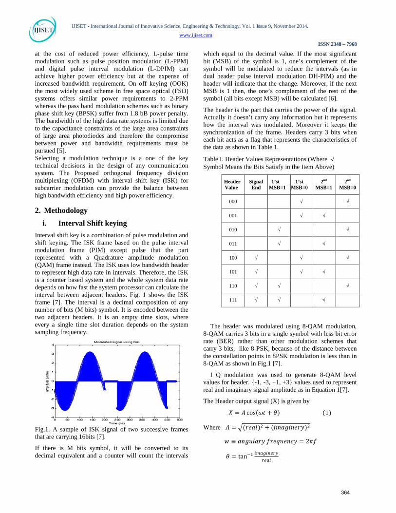
i. Interval Shift keying Interval shift key is a combination of pulse modulation and shift keying. The ISK frame based on the pulse interval modulation frame (PIM) except pulse that the part represented with a Quadrature amplitude modulation (QAM) frame instead. The ISK uses low bandwidth header to represent high data rate in intervals. Therefore, the ISK is a counter based system and the whole system data rate depends on how fast the system processor can calculate the interval between adjacent headers. Fig. 1 shows the ISK frame [7]. The interval is a decimal composition of any number of bits (M bits) symbol. It is encoded between the two adjacent headers. It is an empty time slots, where every a single time slot duration depends on the system sampling frequency.
Fig.1. A sample of ISK signal of two successive frames that are carrying 16bits [7].
If there is M bits symbol, it will be converted to its decimal equivalent and a counter will count the intervals
which equal to the decimal value. If the most significant bit (MSB) of the symbol is 1, one’s complement of the symbol will be modulated to reduce the intervals (as in dual header pulse interval modulation DH-PIM) and the header will indicate that the change. Moreover, if the next MSB is 1 then, the one’s complement of the rest of the symbol (all bits except MSB) will be calculated [6].
The header is the part that carries the power of the signal. Actually it doesn’t carry any information but it represents how the interval was modulated. Moreover it keeps the synchronization of the frame. Headers carry 3 bits when each bit acts as a flag that represents the characteristics of the data as shown in Table 1.
Table I. Header Values Representations (Where √ Symbol Means the Bits Satisfy in the Item Above)
Header Value
Signal End
1’st MSB=1
1’st MSB=0
2P
ndP
MSB=1 2P
ndP
MSB=0
000 √ √
001 √ √
010 √ √
011 √ √
100 √ √ √
101 √ √ √
110 √ √ √
111 √ √ √
The header was modulated using 8-QAM modulation, 8-QAM carries 3 bits in a single symbol with less bit error rate (BER) rather than other modulation schemes that carry 3 bits, like 8-PSK, because of the distance between the constellation points in 8PSK modulation is less than in 8-QAM as shown in Fig.1 [7].
I Q modulation was used to generate 8-QAM level values for header. {-1, -3, +1, +3} values used to represent real and imaginary signal amplitude as in Equation 1[7].
The Header output signal (X) is given by
𝑋 = 𝐴 cos(𝜔𝑡 + 𝜃) (1)
Where 𝐴 = �(𝑟𝑒𝑎𝑙)2 + (𝑖𝑚𝑎𝑔𝑖𝑛𝑒𝑟𝑦)2
𝑤 ≡ 𝑎𝑛𝑔𝑢𝑙𝑎𝑟𝑦 𝑓𝑟𝑒𝑞𝑢𝑒𝑛𝑐𝑦 = 2𝜋𝑓
𝜃 = tan−1 𝑖𝑚𝑎𝑔𝑖𝑛𝑒𝑟𝑦𝑟𝑒𝑎𝑙
364
IJISET - International Journal of Innovative Science, Engineering & Technology, Vol. 1 Issue 9, November 2014.
www.ijiset.com
ISSN 2348 – 7968
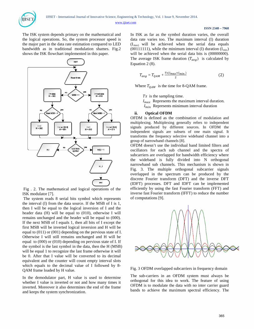
The ISK system depends primary on the mathematical and the logical operations. So, the system processor speed is the major part in the data rate estimation compared to LED bandwidth as in traditional modulation shames. Fig.2 shows the ISK flowchart implemented in this paper.
Fig . 2. The mathematical and logical operations of the ISK modulator [7]. The system reads 8 serial bits symbol which represents the interval (I) from the data source. If the MSB of I is 1, then I will be equal to the logical inversion of I and the header data (H) will be equal to (010), otherwise I will remains unchanged and the header will be equal to (000). If the next MSB of I equals 1, then all bits of I except the first MSB will be inverted logical inversion and H will be equal to (011) or (001) depending on the pervious state of I. Otherwise I will still remains unchanged and H will be equal to (000) or (010) depending on pervious state of I. If the symbol is the last symbol in the data, then the H (MSB) will be equal 1 to recognize the last frame otherwise it will be 0. After that I value will be converted to its decimal equivalent and the counter will count empty interval slots which equals to the decimal value of I followed by 8-QAM frame loaded by H value.
In the demodulator part, H value is used to determine whether I value is inverted or not and how many times it inverted. Moreover it also determines the end of the frame and keeps the system synchronization.
In ISK as far as the symbol duration varies, the overall data rate varies too. The maximum interval (I) duration (IRmax) Rwill be achieved when the serial data equals (00111111), while the minimum interval (I) duration (IRminR) will be achieved when the serial data bits is (00000000). The average ISK frame duration (𝑇𝑎𝑣𝑔) is calculated by Equation 2 (8).
𝑇𝑎𝑣𝑔 = 𝑇𝑄𝐴𝑀 + 𝑇𝑠(𝐼𝑚𝑎𝑥+𝐼𝑚𝑖𝑛 )2
(2)
Where 𝑇𝑄𝐴𝑀 R R is the time for 8-QAM frame.
𝑇𝑠 is the sampling time. 𝐼𝑚𝑎𝑥 Represents the maximum interval duration. 𝐼𝑚𝑖𝑛 Represents minimum interval duration
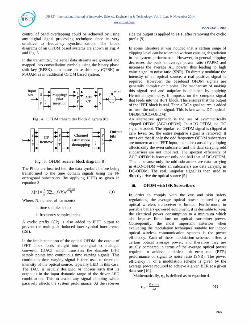
ii. Optical OFDM OFDM is defined as the combination of modulation and multiplexing. Multiplexing generally refers to independent signals produced by different sources. In OFDM the independent signals are subsets of one main signal. It transforms the frequency selective wideband channel into a group of narrowband channels [8]. OFDM doesn’t use the individual band limited filters and oscillators for each sub channel and the spectra of subcarriers are overlapped for bandwidth efficiency where the wideband is fully divided into N orthogonal narrowband sub channels. This mechanism is shown in Fig. 3. The multiple orthogonal subcarrier signals overlapped in the spectrum can be produced by the discrete Fourier transform (DFT) and the inverse DFT (IDFT) processes. DFT and IDFT can be implemented efficiently by using the fast Fourier transform (FFT) and inverse fast Fourier transform (IFFT) to reduce the number of computations [9].
Fig. 3 OFDM overlapped subcarriers in frequency domain
The sub-carriers in an OFDM system must always be orthogonal for this idea to work. The feature of using OFDM is to modulate the data with no inter carrier guard bands to achieve the maximum spectral efficiency. The
365
IJISET - International Journal of Innovative Science, Engineering & Technology, Vol. 1 Issue 9, November 2014.
www.ijiset.com
ISSN 2348 – 7968
control of band overlapping could be achieved by using any digital signal processing technique since its very sensitive to frequency synchronization. The block diagrams of an OFDM based systems are shown in Fig. 4 and Fig. 5.
In the transmitter, the serial data streams are grouped and mapped into constellation symbols using the binary phase shift key (BPSK), quadrature phase shift key (QPSK) or M-QAM as in traditional OFDM based system.
Fig . 4. OFDM transmitter block diagram [8].
Fig . 5. OFDM receiver block diagram [8].
The Pilots are inserted into the data symbols before being transformed to the time domain signals using the N-orthogonal subcarriers (by applying IFFT) as given in equation 3.
X[n] = 1𝑁
∑ 𝑋(𝑘)𝑒𝑗2𝜋𝑛𝑘𝑁𝑁
𝑛=1 (3)
Where: N: number of harmonics
n: time samples index
k: frequency samples index
A cyclic prefix (CP) is also added to IFFT output to prevent the multipath -induced inter symbol interference (ISI).
In the implementation of the optical OFDM, the output of IFFT block feeds straight into a digital to analogue convertor (DAC) which translates the discrete IFFT sample points into continuous time varying signals. This continuous time varying signal is then used to drive the intensity of the optical source, typically LED in this case. The DAC is usually designed or chosen such that its output is in the input dynamic range of the driver LED combination. This to avoid any signal clipping which passively affects the system performance. At the receiver
side the output is applied to FFT, after removing the cyclic prefix [9].
In some literature it was noticed that a certain range of clipping level can be tolerated without causing degradation in the system performance. However, in general clipping decreases the peak to average power ratio (PAPR) and increases the average AC power, thus leading to high value signal to noise ratio (SNR). To directly modulate the intensity of an optical source, a real positive signal is required. However, the baseband OFDM signals are generally complex or bipolar. The mechanism of making this signal real and unipolar is obtained by applying Hermitian symmetry. It imposes on the complex signal that feeds into the IFFT block. This ensures that the output of the IFFT block is real. Then a DC signal source is added to form the unipolar signal. This is known as DC-optical-OFDM (DCO-OFDM). An alternative approach is the use of asymmetrically clipped OFDM (ACO-OFDM). In ACO-OFDM, no DC signal is added. The bipolar real OFDM signal is clipped at zero level. So, the entire negative signal is removed. It turns out that if only the odd frequency OFDM subcarriers are nonzero at the IFFT input, the noise caused by clipping affects only the even subcarrier and the data carrying odd subcarriers are not impaired. The spectral efficiency of ACO-OFDM is however only one-half that of DC-OFDM. This is because only the odd subcarriers are data carrying in ACO-OFDM while all subcarriers are data carrying in DC-OFDM. The real, unipolar signal is then used to directly drive the optical source [5].
iii. OFDM with ISK Subscribers
In order to comply with the eye and skin safety regulations, the average optical power emitted by an optical wireless transceiver is limited. Furthermore, in portable battery-powered equipment, it is desirable to keep the electrical power consumption to a minimum which also imposes limitations on optical transmitter power. Consequently, the most important criterion when evaluating the modulation techniques suitable for indoor optical wireless communication systems is the power efficiency. Each of these modulation schemes offers a certain optical average power, and therefore they are usually compared in terms of the average optical power required to achieve a desired bit error rate (BER) performance or signal to noise ratio (SNR). The power efficiency ηRpR of a modulation scheme is given by the average power required to achieve a given BER at a given data rate [10].
Mathematically, ηRpR is defined as in equation 4.
ηRpR = 𝐸 𝑝𝑢𝑙𝑠𝑒𝐸𝑏
(4)
366
IJISET - International Journal of Innovative Science, Engineering & Technology, Vol. 1 Issue 9, November 2014.
www.ijiset.com
ISSN 2348 – 7968
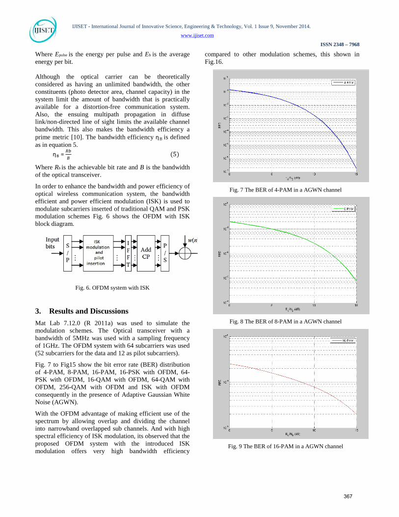
Where Epulse is the energy per pulse and Eb is the average energy per bit. Although the optical carrier can be theoretically considered as having an unlimited bandwidth, the other constituents (photo detector area, channel capacity) in the system limit the amount of bandwidth that is practically available for a distortion-free communication system. Also, the ensuing multipath propagation in diffuse link/non-directed line of sight limits the available channel bandwidth. This also makes the bandwidth efficiency a prime metric [10]. The bandwidth efficiency ηRBR is defined as in equation 5.
ηRBR = 𝑅𝑏𝐵
(5)
Where Rb is the achievable bit rate and B is the bandwidth of the optical transceiver.
In order to enhance the bandwidth and power efficiency of optical wireless communication system, the bandwidth efficient and power efficient modulation (ISK) is used to modulate subcarriers inserted of traditional QAM and PSK modulation schemes Fig. 6 shows the OFDM with ISK block diagram.
Fig. 6. OFDM system with ISK
3. Results and Discussions Mat Lab 7.12.0 (R 2011a) was used to simulate the modulation schemes. The Optical transceiver with a bandwidth of 5MHz was used with a sampling frequency of 1GHz. The OFDM system with 64 subcarriers was used (52 subcarriers for the data and 12 as pilot subcarriers).
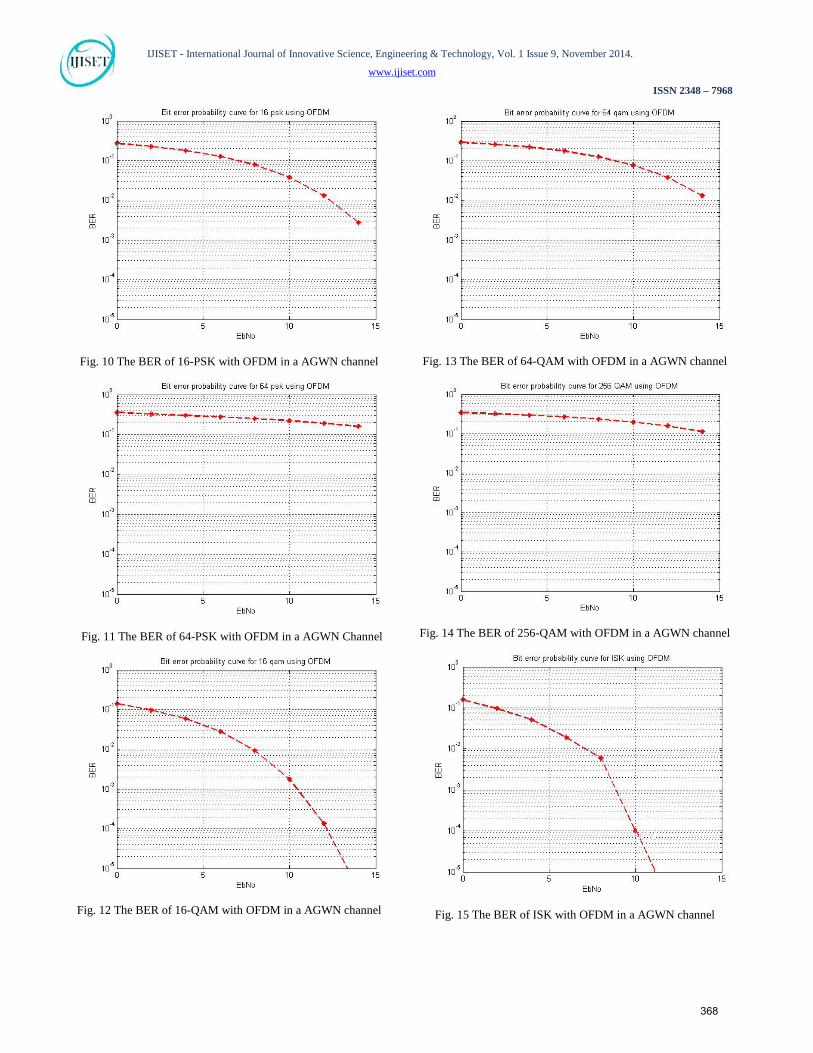
Fig. 7 to Fig15 show the bit error rate (BER) distribution of 4-PAM, 8-PAM, 16-PAM, 16-PSK with OFDM, 64-PSK with OFDM, 16-QAM with OFDM, 64-QAM with OFDM, 256-QAM with OFDM and ISK with OFDM consequently in the presence of Adaptive Gaussian White Noise (AGWN).
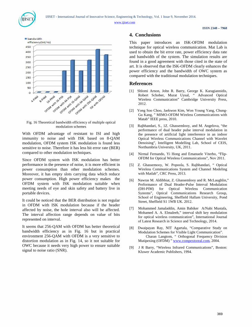
With the OFDM advantage of making efficient use of the spectrum by allowing overlap and dividing the channel into narrowband overlapped sub channels. And with high spectral efficiency of ISK modulation, its observed that the proposed OFDM system with the introduced ISK modulation offers very high bandwidth efficiency
compared to other modulation schemes, this shown in Fig.16.
Fig. 7 The BER of 4-PAM in a AGWN channel
Fig. 8 The BER of 8-PAM in a AGWN channel
Fig. 9 The BER of 16-PAM in a AGWN channel
367
IJISET - International Journal of Innovative Science, Engineering & Technology, Vol. 1 Issue 9, November 2014.
www.ijiset.com
ISSN 2348 – 7968
Fig. 10 The BER of 16-PSK with OFDM in a AGWN channel
Fig. 11 The BER of 64-PSK with OFDM in a AGWN Channel
Fig. 12 The BER of 16-QAM with OFDM in a AGWN channel
Fig. 13 The BER of 64-QAM with OFDM in a AGWN channel
Fig. 14 The BER of 256-QAM with OFDM in a AGWN channel
Fig. 15 The BER of ISK with OFDM in a AGWN channel
368
IJISET - International Journal of Innovative Science, Engineering & Technology, Vol. 1 Issue 9, November 2014.
www.ijiset.com
ISSN 2348 – 7968
Fig. 16 Theoretical bandwidth efficiency of multiple optical
modulation schemes
With OFDM advantage of resistant to ISI and high immunity to noise and with ISK based on 8-QAM modulation, OFDM system ISK modulation is found less sensitive to noise. Therefore it has less bit error rate (BER) compared to other modulation techniques.
Since OFDM system with ISK modulation has better performance in the presence of noise, it is more efficient in power consumption than other modulation schemes. Moreover, it has empty slots carrying data which reduce power consumption. High power efficiency makes the OFDM system with ISK modulation suitable when meeting needs of eye and skin safety and battery live in portable devices.
It could be noticed that the BER distribution is not regular in OFDM with ISK modulation because if the header affected by noise, the hole interval also will be affected. The interval affection range depends on value of bits represented on interval.
It seems that 256-QAM with OFDM has better theoretical bandwidth efficiency as in Fig. 16 but in practical environment 256-QAM with OFDM is a very sensitive to distortion modulation as in Fig. 14, so it not suitable for OWC because it needs very high power to ensure suitable signal to noise ratio (SNR).
4. Conclusions This paper introduces an ISK-OFDM modulation technique for optical wireless communication. Mat Lab is used to obtain the bit error rate, power efficiency data rate and bandwidth of the system. The simulation results are found in a good agreement with those cited in the state of art. It is observed that the ISK-OFDM clearly enhances the power efficiency and the bandwidth of OWC system as compared with the traditional modulation techniques.
References [1] Shlomi Arnon, John R. Barry, George K. Karagiannidis,
Robert Schober, Murat Uysal, “ Advanced Optical Wireless Communication” Cambridge University Press, 2012.
[2] Yong Soo Choo, Jaekwon Kim, Won Young Yang, Chung-Gu Kang, ” MIMO-OFDM Wireless Communications with Matab” IEEE press, 2010.
[3] Rajbhandari, S., 1Z. Ghassemlooy, and M. Angelova, “the performance of dual header pulse interval modulation in the presence of artificial light interference in an indoor Optical Wireless Communications Channel with Wavelet Denoising”, Intelligent Modelling Lab, School of CEIS, Northumbria University, UK, 2011.
[4] Nirmal Fernando, Yi Hong and Emanuele Viterbo, “Flip-OFDM for Optical Wireless Communications”, Nov 2011.
[5] Z. Ghassemooy, W. Popoola, S. Rajbhandari, “ Optical Wireless Communications System and Channel Modeling with Matlab”, CRC Press, 2013.
16T[6] Nawras M. Aldibbiat, Z. Ghassemlooy and R. McLaughlin,” Performance of Dual Header-Pulse Interval Modulation (DH-PIM) for Optical Wireless Communication Systems”, 16TOptical Communications Research Group, School of Engineering, Sheffield Hallam University, Pond Street, Sheffield S1 1WB UK. 2012.
16T[7] Mohammed Jamaladdin, Amin Babiker A/Nabi Mustafa, Mohamed A. A. Elmaleeh,” interval shift key modulation for optical wireless communication”, International Journal of Latest Research in Science and Technology, 2014.
[8] Dwaipayan Ray, NIT Agartala, “16TComparative Study on Modulation Schemes for Visible Light Communication 16T”.
16T Charan Langtom, “ Orthogonal Frequency Division Mutipexing (OFDM) ” 16T23TUwww.compextoreal.comU16T23T, 2004.
16T[9] J R Barry, “Wireless Infrared Communications”, Boston: Kluwer Academic Publishers, 1994.
369