iSoRA: Humanoid Robot Arm for Intelligent Haptic...
32
Advanced Robotics 23 (2009) 1327–1358 www.brill.nl/ar Full paper iSoRA: Humanoid Robot Arm for Intelligent Haptic Interaction with the Environment Dzmitry Tsetserukou ∗ , Naoki Kawakami and Susumu Tachi Department of Information Physics and Computing, University of Tokyo, 7-3-1 Hongo, Bunkyo-ku, Tokyo 113-8656, Japan Received 5 November 2008; accepted 7 February 2009 Abstract The paper concentrates on the development and control of the humanoid robot arm iSoRA, intended for operation in a dynamic unstructured environment. Optical torque sensors integrated into each joint enable measurement of contacting forces along the entire manipulator surface. A variable admittance control strat- egy was elaborated to increase the robot functionality and to achieve the human-like dynamics of interaction. The experimental results show that the proposed approach not only provides safe interaction of the robot arm with a person, but also improves the effectiveness of contact task performance. The paper also presents a novel concept of avoidance of an obstacle of unknown shape. The tactile sensory ability of the developed manipulator allows robot links to follow the object contour and to perform motion planning in the dynamic environment. The information on the applied normal force vector, object shape and target point coordinates is supplied to the motion planning system. The algorithms for contact point detection, object geometry recognition, and estimation of contacting object stiffness are detailed. The numerical simulation elicits a capability of the proposed method to approximate various object shapes precisely. The experimental results showed that the local admittance control and motion planner allowed the end-effector to follow the object contour in a very smooth, consistent manner while reaching the target point. © Koninklijke Brill NV, Leiden and The Robotics Society of Japan, 2009 Keywords Humanoid robot arm, variable admittance control, human–robot interaction, obstacle avoidance, optical torque sensor 1. Introduction Service robotics aimed at assisting humans in everyday life environments is nowa- days gaining increased interest from researchers and industry. Such robots are programmed to perform continuously changing tasks in unstructured human envi- * To whom correspondence should be addressed. E-mail: [email protected] © Koninklijke Brill NV, Leiden and The Robotics Society of Japan, 2009 DOI:10.1163/156855309X462619
Transcript of iSoRA: Humanoid Robot Arm for Intelligent Haptic...

Advanced Robotics 23 (2009) 1327–1358www.brill.nl/ar
Full paper
iSoRA: Humanoid Robot Arm for Intelligent HapticInteraction with the Environment
Dzmitry Tsetserukou ∗, Naoki Kawakami and Susumu Tachi
Department of Information Physics and Computing, University of Tokyo, 7-3-1 Hongo, Bunkyo-ku,Tokyo 113-8656, Japan
Received 5 November 2008; accepted 7 February 2009
AbstractThe paper concentrates on the development and control of the humanoid robot arm iSoRA, intended foroperation in a dynamic unstructured environment. Optical torque sensors integrated into each joint enablemeasurement of contacting forces along the entire manipulator surface. A variable admittance control strat-egy was elaborated to increase the robot functionality and to achieve the human-like dynamics of interaction.The experimental results show that the proposed approach not only provides safe interaction of the robotarm with a person, but also improves the effectiveness of contact task performance. The paper also presentsa novel concept of avoidance of an obstacle of unknown shape. The tactile sensory ability of the developedmanipulator allows robot links to follow the object contour and to perform motion planning in the dynamicenvironment. The information on the applied normal force vector, object shape and target point coordinatesis supplied to the motion planning system. The algorithms for contact point detection, object geometryrecognition, and estimation of contacting object stiffness are detailed. The numerical simulation elicits acapability of the proposed method to approximate various object shapes precisely. The experimental resultsshowed that the local admittance control and motion planner allowed the end-effector to follow the objectcontour in a very smooth, consistent manner while reaching the target point.© Koninklijke Brill NV, Leiden and The Robotics Society of Japan, 2009
KeywordsHumanoid robot arm, variable admittance control, human–robot interaction, obstacle avoidance, opticaltorque sensor
1. Introduction
Service robotics aimed at assisting humans in everyday life environments is nowa-days gaining increased interest from researchers and industry. Such robots areprogrammed to perform continuously changing tasks in unstructured human envi-
* To whom correspondence should be addressed. E-mail: [email protected]
© Koninklijke Brill NV, Leiden and The Robotics Society of Japan, 2009 DOI:10.1163/156855309X462619

1328 D. Tsetserukou et al. / Advanced Robotics 23 (2009) 1327–1358
ronments. Both coexistence, when the human and robot share the same workspace,and cooperation, when the human and robot work on the same task, impose strictrequirements on manipulator behavior and control in order to ensure safe interac-tion with the environment, effectiveness of target task execution and ergonomiccooperation.
Classical motion planning algorithms for general manipulators in cluttered envi-ronments first construct the robot configuration space with a known set of stationaryobstacles and then generate collision-free motions in the configuration space [1]. Inthe case of real indoor environments, known obstacles (e.g., chairs, tables, etc.) andunknown obstacles (persons approaching the robot, unmapped environment, etc.)change their location dynamically. Moreover, the object shape, speed and positioncan also alter in an unpredictable way, leading to obstruction of the planned robotmotion.
Thus, the robot control system faces three main issues: (1) establishing safe phys-ical contact with environment, (2) planning collision-free motion and recognition ofobstacle shapes, and (3) directing the robot to its goal position. To meet these chal-lenges, sensor-based planning making use of real-time sensor information about thesurroundings is needed.
For an autonomous mobile robot moving in an unknown environment, non-tactilesensors are normally used. A variety of algorithms for shape recognition from cam-era images has been developed (e.g., stereo vision, optical flow). However, thesetechniques usually require a lot of computation and, therefore, are not suitable forreal-time use [2].
When it comes to a multi-d.o.f. robot manipulator working in an unknown envi-ronment, the issues of obstacle avoidance become much more complicated becauseof the high risk of collision of each joint and each link of the robot arm with an ob-stacle. The most effective solution for preventing collisions is to endow the wholerobot arm with the ability to safely contact and interact with environment in real-time. Lumelsky [3] pioneered the idea to cover a manipulator with a sensitive skincapable of detecting nearby objects. An array of infrared proximity sensors deliversthe information about any obstacles obstructing the arm motion to the control sys-tem. The algorithm of the motion planner maneuvers the robot arm, thus avoidingcontact [4, 5]. Recently, a high-speed vision system attached to the robot manipu-lator for collision avoidance was developed [6].
We argue that the robot arm should be controlled not to avoid physical contact,but rather to ensure safe tactile interaction with the environment during obstacleavoidance. The benefits of such interaction are obvious. The robot can acquireplenty of fundamental information about objects by touch (shape, stiffness, tex-ture, location, fixation, etc.) and plan its motion in the most optimal fashion. Itshould be noted that tasks under human supervision, such as transporting the ob-ject, leading the robot tip via force-following and performing the assembling tasks,require the processing algorithm of the contact state. Conventional approaches tohandle the physical interaction between a manipulator and environment are based

D. Tsetserukou et al. / Advanced Robotics 23 (2009) 1327–1358 1329
on the impedance control of a robot arm tip [7]. However, the other parts of the ro-bot body (forearm, elbow, upper arm, shoulder and torso) are insensitive to contactand present significant danger not only to humans, but also to the robot structureitself. Generally, two techniques of safe interaction with the entire robot arm arewell recognized, i.e., passive compliance control and active force control.
Whereas mechanical leaf springs [8] and variable stiffness actuators [9] inte-grated into each joint allow achieving a fast response to an external disturbance,they also cause vibrations destabilizing the dynamic behavior. Additionally, therobot control in such cases is complicated by many unknown parameters (e.g., ac-tuator stiffness and damping). Another approach to improve the intrinsic safety ofthe robot is to reduce the weight of components. The main drawback of this methodis the occurrence of undamped structural vibrations.
Active force control implies that the robot structure is stiff enough to providehigh position accuracy and contact ability with environment is achieved by exces-sive sensory system feedback [10]. However, due to the time lag induced by thesampling process, such robots pose dangers at the moment of impact. Mitsunaga etal. [11] progressively improved the tactile ability of the robot through covering itsentire body with piezoelectric film-based tactile sensors. Since this device integratesa huge amount of small sensors incorporated into soft layer, and requires compli-cated wiring and signal processing hardware, it has high cost and reliability issues.
2. Robot Arm and Sensory System
To realize the safe physical contact of the entire robot arm structure with hu-mans and to guarantee obstacle avoidance, we developed a whole-sensitive robotarm iSoRA (intelligent Soft Robot Arm) (by using distributed torque sensors ineach joint). When contact with the environment occurs, the manipulator automati-cally generates compliant motion according to the measured external force (activecontrol). Thus, the whole structure of the manipulator can safely interact with anunstructured environment. The torque sensors introduce compliances, which softenthe impact forces on the initial state of the contact transient (passive control).
The developed robot arm iSoRA (Fig. 1) has 4 d.o.f.: roll, pitch and yaw jointsof a shoulder, and a pitch joint of an elbow. Such orthogonal disposition of the axessimplifies the installation of the torque sensors and motor drives into the joints.Coordinate systems based on the Denavit–Hartenberg convention are representedin Fig. 2. The 8-d.o.f. robot hand allows performing dexterous manipulations.
Each robot joint is equipped with an optical torque sensor. The sizes and appear-ance of the arm were chosen so that any sense of incongruity during interaction witha human is avoided. We kept the arm proportions the same as in an average heighthuman, aged 25: upper arm length L1 0.308 m, upper arm circumference 0.251 m,forearm length L2 0.241 m and forearm circumference 0.189 m.
The specific application (i.e., a robot arm interacting with human beings in asafe manner) introduces special requirements for the design of the torque sensor.

1330 D. Tsetserukou et al. / Advanced Robotics 23 (2009) 1327–1358
Figure 1. Robot arm iSoRA.
Figure 2. Coordinate system.
In order to facilitate the realization of torque measurement in each arm joint, wedeveloped new optical torque sensors based on results presented in Refs [12, 13].The novelty of our method is the application of the ultra-small-size photointerrupter(PI) RPI-121 as a sensitive element to measure the relative motion of sensor com-ponents. The dimensions of the PI (3.6 mm × 2.6 mm × 3.3 mm) and its weight of0.05 g allow realization of a compact design. The spring components were manufac-tured from one piece of AISI 4135 steel using a wire electrical discharge machining.The optical torque sensor is set between the driving shaft of the harmonic transmis-sion and driven shaft of the joint (Fig. 3). When the load is applied to the robotjoint, the magnitude of the output signal from PI corresponds to the exerted load.

D. Tsetserukou et al. / Advanced Robotics 23 (2009) 1327–1358 1331
Figure 3. Torque sensor of the elbow joint and calibration results. (a) Optical torque sensor. (b) Cali-bration results.
The sensors attached to the first, second and third/fourth joints were designed tomeasure torques of ±12.5, ±10.5 and ±4.5 Nm, respectively. A non-linearity of2.5% FS was calculated using the maximum deviated value from the best-fit line.The developed optical torque sensors are characterized by high dependability, goodaccuracy (even in electrically noisy environments), low price, compact size, lightweight, and easy mounting procedure.
3. Intelligent Variable Admittance Control
3.1. Joint Impedance Control
The dynamic equation of an n-d.o.f. manipulator in joint space coordinates (duringinteraction with the environment) is given by:
M(θ)θ̈ + C(θ, θ̇)θ̇ + τf(θ̇) + G(θ) = τ + τEXT, (1)
where θ , θ̇ and θ̈ are the joint angle, the joint angular velocity and the joint angleacceleration, respectively, M(θ) ∈ Rn×n is the symmetric positive definite inertiamatrix, C(θ, θ̇) ∈ Rn is the vector of Coriolis and centrifugal torques, τf(θ̇) ∈ Rn isthe vector of actuator joint friction torques, G(θ) ∈ Rn is the vector of gravitationaltorques, τ ∈ Rn is the vector of actuator joint torques, and τEXT ∈ Rn is the vectorof external disturbance joint torques.
People can perform dexterous contact tasks in daily activities, regulating theirown dynamics according to a time-varying environment. To achieve skillful human-like behavior, the humanoid robot has to be able to change its dynamic character-istics depending on time-varying interaction forces. The most efficient method ofcontrolling the interaction between a manipulator and an environment is impedancecontrol [14]. This approach enables us to regulate response properties of the ro-bot to external forces through modifying the mechanical impedance parameters.A schematic representation of joint impedance control is given in Fig. 4.
The desired impedance properties of the ith joint of manipulator can be ex-pressed as:
Jdi�θ̈i + Ddi�θ̇i + Kdi�θi = τEXTi; �θi = θci − θdi , (2)

1332 D. Tsetserukou et al. / Advanced Robotics 23 (2009) 1327–1358
Figure 4. Concept of the local impedance control: when external force FEXT is applied to the robotlink i + 1, assigned values of desired inertia Jd(i+1), damping Dd(i+1) and stiffness Kd(i+1) of thei + 1 joint define the dynamic properties of this robot joint in response to the exerted external torqueτEXT(i+1).
where Jdi , Ddi and Kdi are the desired inertia, damping and stiffness of the ith joint,respectively, τEXTi is the torque applied to ith joint and caused by external forces,and �θi is the difference between the current position θci and desired position θdi .The state-space presentation of the equation of local impedance control is writtenas: [
�θ̇i
v̇i
]=
[0 1
−Kdi/Jdi −Ddi/Jdi
][θi
vi
]+
[0
1/Jdi
]τEXTi (t), (3)
or: [�θ̇i
v̇i
]= A
[θi
vi
]+ BτEXTi (t), (4)
where the state variable is defined as vi = �θ̇i , and A and B are matrices. Afterintegration of (4), the discrete time presentation of the impedance equation is ex-pressed as: [
�θk+1�θ̇k+1
]= Ad
[�θk
�θ̇k
]+ BdTEXT(k). (5)
To achieve the fastest possible non-oscillatory response to the external force, weassigned the eigenvalues λ1 and λ2 of matrix A as real and equal to λ1 = λ2 = λ,λ > 0. By using the Cayley–Hamilton method for matrix exponential determination,we have:
Ad = eλT
[1 − λT T
−KdT/Jd 1 − λT − DdT/Jd
], (6)
Bd = (Ad − I )A−1B = − 1
Kd
[eλT (1 − λT ) − 1
−(Dd/(2Jd))2T eλT
], (7)
where T is the sampling time and I is the identity matrix.

D. Tsetserukou et al. / Advanced Robotics 23 (2009) 1327–1358 1333
There are several conflicting requirements on the choice of dynamics parame-ters of the impedance model to provide effectiveness and functionality of a servicerobot in tasks of physical interactions fulfilled in cooperation with humans and toensure the collision avoidance. For example, while accomplishing service tasks forhumans in the autonomous mode, it is required to provide high stiffness (to ensuresmall position error during object handling) and high damping (for good veloc-ity tracking). Realization of human-following motion, mainly used in performingcooperative tasks, also imposes specific requirements on the desired impedance pa-rameter selection. In this approach, by applying force to the robot arm, it is possibleto intuitively operate the humanoid robot motion along the force and speed direc-tion without considering any command signals. In the case of a collision, the verysmall stiffness is obligatory to reduce the impact forces.
Basically, there are two types of solution of this problem: adaptive and func-tional adjustments of impedance parameters. In adaptive control, the damping andstiffness of the system are gradually adjusted according to sensed dynamics andcontact forces [15]. However, due to parametric uncertainties of the robot dynamicsmodel, it is difficult to obtain the complete description of the dynamics. Therefore,model-based adaptive impedance control must rely on either repeated motions ortime for adaptation to achieve convergence to the desired system parameters. Forsystems with more than 1 d.o.f., such an approach can hardly be applied. In thefunctional approaches, current impedance parameters have predetermined relationsto the current sensed variables. Generally, these methods presume determining thecurrent stiffness and damping matrices functionally dependent on sensed variables.The main idea of Ref. [16] is that the contact between the slave robot and the envi-ronment can be classified according to the angle between the commanded velocityand the contact force. It is supposed that force and velocity vectors are usuallyparallel when the impact occurs or when the object is being pushed. Thus, the func-tional dependency of stiffness and damping on the angle between sensed force andvelocity vectors was proposed. In real cooperation tasks and, especially, collisions,these vectors can not only be parallel, but also have independent arbitrary directionsaccording to the direction of the external force.
Another line of variable impedance research is directed to the estimation ofhuman arm stiffness [17]. The proposed variable impedance controller varies adamping parameter of target impedance in proportion to an estimated value of thehuman arm stiffness. Despite the fact that humanoid robot arm can effectively fol-low the human arm motion, it cannot perform tasks autonomously. Besides, onlyimpedance parameters of the robot end-effector can be adjusted. We elaborated anew methodology for impedance parameter adjustment based on the physical inter-action mode and providing the dynamic stability of the system.
3.2. Intelligent Variable Joint Admittance Control
It was found that humans adjust their joint stiffness to accommodate changes insurface stiffness [18]. Furthermore, the research on impedance characteristics of a

1334 D. Tsetserukou et al. / Advanced Robotics 23 (2009) 1327–1358
human arm shows that, while pushing or pulling the object naturally, the humanarm stiffness and damping behavior can be approximated by exponential curves[19]. The first essential peculiarity of the new control method is that we introducethe exponential functional dependency between the sensed force and stiffness toimpart the human-like damping and stiffness behavior to the robot arm interactingwith the environment. The second main feature originates from the fundamentalconflict in impedance selection with regard to current working conditions. We con-sider the threshold of the external disturbance torque value τEXTth to distinguishthe service task (with high stiffness and damping of joints) from human-followingmotion tasks requiring low stiffness. This value can be chosen depending on theforce necessary to accomplish the service task (e.g., lifting a box and physicallysupporting a disabled human require individual values of forces generated by therobot arm). We assigned the specific magnitude of τEXTth to each joint of the robotarm. The third distinctive contribution is the recognition of the collision based onthe time derivative of the joint torque.
3.2.1. Control for Accomplishment of Service Tasks and Human-Following MotionThe procedure of impedance parameters selection is illustrated by the example ofthe elbow joint as follows. In the first stage, the parameters of desirable impedancemodel of the robot are computed for the case of service task accomplishment and theaverage level of contact force of the human–robot interaction. The desired stiffnessKd1 (for the static equilibrium case) is calculated from (8) based on the maximumdeflection value of the joint angle �θmax caused by external torque τEXT whileperforming the service task:
Kd1 = τEXT
�θmax. (8)
It was defined that a external torque of 1 Nm results in �θi max of 0.1 rad givingKd1 of 10 (Nm/rad). The desired damping is expressed as:
Dd1 = 2ζ√
Kd1Jd1. (9)
To realize a fast non-oscillatory response on the external torque, we defined thedamping coefficient ζ as 1.05. The value of desired inertia Jd1 of 0.1 (kg·m2) wasassigned to realize fast response tracking. Thus, the value Dd1 of 2.1 (Nm·s/rad)was derived from (9). These parameters are valid till the interaction force does notcause any overload of robot arm. When the sensed value of the torque is higherthan the threshold level, the robot recognizes this condition as the human-followingmotion mode and adjusts its dynamics parameters (stiffness and damping) in thesame way as a human in order to provide smooth natural interaction. To realizesuch continuous change of dynamics, we use an exponential relation between theexternal disturbance torque and desired stiffness:
Kd2 = Kd1eμ(τEXT−τEXTth), (10)

D. Tsetserukou et al. / Advanced Robotics 23 (2009) 1327–1358 1335
where Kd2 is the desired stiffness on the second stage of the interaction, and μ isthe coefficient defining the level of decreasing the arm joint stiffness in response toincreasing the difference between external torque and torque threshold.
The desired damping is adjusted to prevent force responses from being too slug-gish while changing stiffness values and to ensure contact stability:
Dd2 = 2.1√
Kd2Jd1 = 2.1e0.5μ(τEXT−τEXTth)√
Kd1Jd1. (11)
Then, the variable joint impedance controller is described by:
Jdi�θ̈i + 2.1e0.5μ(τEXTi−τEXTth)√
Kd1Jd1�θ̇i + Kd1eμ(τEXTi−τEXTth)�θi
= τEXTi;�θi = θci − θdi . (12)
To verify the theory and to evaluate the feasibility and performance of theproposed impedance controller, experiments with the iSoRA robot arm were con-ducted. To ensure the effectiveness of service task accomplishment, we decided toimplement position-based impedance control (admittance control) (Fig. 5, Kp, Kv,TG and TZ denote proportional gain, derivative gain of PD controller, torque causedby gravity forces, and torque measured by torque sensor, respectively). In this algo-rithm, the compliant trajectory generated by the impedance controller is tracked bythe PD control loop.
During the experiment, the interaction with arm was performed to exceed thejoint torque threshold level (τEXTth of 0.6 Nm was assigned, μ = −1.155). Theexperimental results for the elbow joint — applied torque, impedance trajectorieswith constant (conventional approach) and variable coefficients (proposed intelli-gent variable joint admittance control), variable stiffness plot, variable damping
Figure 5. Block diagram of intelligent variable admittance control.

1336 D. Tsetserukou et al. / Advanced Robotics 23 (2009) 1327–1358
Figure 6. External torque.
Figure 7. Impedance trajectories.
Figure 8. Variable stiffness Kd2.
plot, applied torque with different magnitudes and corresponding impedance tra-jectories with constant and variable coefficients — are presented in Figs 6–11,respectively.
The experimental results show the successful realization of the variable jointimpedance control. While contacting with the human, the robot arm generates com-pliant soft motion according to the sensed force. The plot presented in Fig. 7 showsthat the variable impedance control provides a softer trajectory to accomplish the

D. Tsetserukou et al. / Advanced Robotics 23 (2009) 1327–1358 1337
Figure 9. Variable damping Dd2.
Figure 10. External torque.
Figure 11. Impedance trajectories.
human-following motion than the impedance control with constant coefficients. Aswe assigned the critically damped response of the impedance model to the distur-bance force, the output angle (�θk+1) has an ascending–descending exponentialtrajectory. As seen from the experimental results shown in Figs 10 and 11, theproposed variable impedance control comprehensively distinguishes and processesthe service tasks (torques under threshold level) and cooperative human-followingtasks (torques above threshold level). As the result of the experiments with the vari-
1338 D. Tsetserukou et al. / Advanced Robotics 23 (2009) 1327–1358
able impedance-controlled arm, tactile sensation of soft friendly interaction wasachieved.
3.2.2. Intelligent Impact ControlIn daily life, a person frequently contacts with an environment. The impact be-tween a limb and the environment is inevitable during the interaction. In order towork in human daily environments, the service robot has to recognize the collisionconditions, and its control system should be able to guide the manipulator quicklyand smoothly so to avoid excessively large impact forces. Different impact controlalgorithms have been proposed. Basically, they focus on preparing for an impactin advance [20] and coping with impact during contact transience [21]. However,due to the unexpected nature of collisions and the lack of a robust control strategyof impact effect minimization, the application area of such approaches is greatlylimited.
We believe that realization of robust impact control should originate from thehuman reflex system. A reflex action is an automatic involuntary neuromuscularaction elicited by a defined stimulus and it can respond to external stimuli with asmall reaction time retracting the limbs away from the object. In our control algo-rithm, impact is processed as follows. When an unexpected collision is detected,the impact control algorithm provides the pre-programmed reflex action of the ro-bot arm. After accomplishing a safe and smooth collision, the control system isreturned to the original mode aimed at distinguishing the service and cooperativetasks.
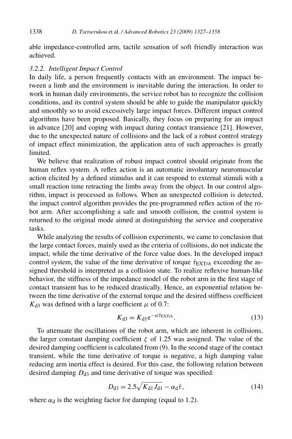
While analyzing the results of collision experiments, we came to conclusion thatthe large contact forces, mainly used as the criteria of collisions, do not indicate theimpact, while the time derivative of the force value does. In the developed impactcontrol system, the value of the time derivative of torque τ̇EXTth exceeding the as-signed threshold is interpreted as a collision state. To realize reflexive human-likebehavior, the stiffness of the impedance model of the robot arm in the first stage ofcontact transient has to be reduced drastically. Hence, an exponential relation be-tween the time derivative of the external torque and the desired stiffness coefficientKd3 was defined with a large coefficient μ of 0.7:
Kd3 = Kd1e−μτ̇EXTth . (13)
To attenuate the oscillations of the robot arm, which are inherent in collisions,the larger constant damping coefficient ζ of 1.25 was assigned. The value of thedesired damping coefficient is calculated from (9). In the second stage of the contacttransient, while the time derivative of torque is negative, a high damping valuereducing arm inertia effect is desired. For this case, the following relation betweendesired damping Dd3 and time derivative of torque was specified:
Dd3 = 2.5√
Kd1Jd1 − αdτ̇ , (14)
where αd is the weighting factor for damping (equal to 1.2).

D. Tsetserukou et al. / Advanced Robotics 23 (2009) 1327–1358 1339
Figure 12. Torque derivation.
Figure 13. Variable stiffness Kd3.
Figure 14. Variable damping Dd3.
The threshold value of the time derivative of torque τ̇EXTth was 2.6 Nm/s. Theexperimental results for the elbow joint — time derivative of applied torque, desiredcollision stiffness Kd3, desired collision damping Dd3 plot, impedance trajectorieswith constant and collision variable coefficients, time derivative of torque for twodifferent contact states and corresponding impedance trajectories — are presentedin Figs 12–17, respectively.
From the plots of experimental results, it is apparent that, when the impact isrecognized (the time derivative of torque becomes larger than the threshold value),

1340 D. Tsetserukou et al. / Advanced Robotics 23 (2009) 1327–1358
Figure 15. Impedance trajectories.
Figure 16. Torque derivation.
Figure 17. Impedance trajectories.
the stiffness and damping are decreasing drastically (Figs 13 and 14), allowingavoidance of large impact forces. In the second stage of the interaction, whenthe impact force is decreasing, the damping coefficient of the impedance model(Fig. 14) is increased to suppress the dynamic oscillations. Figure 16 indicates thatthe nature of cooperation tasks (graph of the time derivative of torque has a smallvalue of local extremum and stretched in time-scale function) completely differsfrom the impact state (graph of the time derivative of torque has a large spike and

D. Tsetserukou et al. / Advanced Robotics 23 (2009) 1327–1358 1341
contracted in time-scale function). The developed control takes advantage of thisfeature to generate reflex action-based motion.
4. Novel Concept of Obstacle Avoidance and Object Exploration ThroughTactile Interaction
4.1. Introduction and Problem Statement
Avoidance of an obstacle with an unknown shape in an unstructured environment isthe fundamental and significant problem in service robotics, which has not yet beensolved in a satisfactory way.
A fairly small amount of work has been done on tactile interaction of the wholerobot arm with the environment. Bauer [22] conducted very practical and useful re-search on haptic exploration of the environment. The idea underlying the algorithmis to identify the free space, object location and object shape by several attemptsmade by the robot arm in order to pass through an obstacle. It should be noted, how-ever, that the proposed system cannot detect the contact point coordinates, requiresa time-consuming obstacle identification process and, as the authors reported, theexploration algorithm fails when several collisions occur simultaneously.
Substantially more research has been done in the field of object exploration andobject recognition by the humanoid robot hand. Okamura et al. [23] introducedan approach for haptic exploration of an unknown object through traversing theobject surface by robot fingers. The process consists of a sequence of phases, inwhich some fingers are responsible for grasping, and others roll and slide over theobject surface. Exploratory strategies for the determination of the object geometrywith haptic sensing have been developed [24, 25]. Instead of mounting a distrib-uted tactile sensor on the finger link, the method described in Ref. [26] roughlydetects a contact and then initiates the motion of the fingertip along the contour.An approach to real-time shape recognition and grasping of unknown objects by arobot hand with soft fingers and an omnidirectional camera is proposed in Ref. [2].The polygon circumscribing the horizontal cross-section of the object is calculatedusing the volume intersection method.
However, the approaches mentioned above are mostly intended for grasping op-timization, not for obstacle avoidance. To cope with the spatial uncertainty of anunknown, unstructured environment, we elaborated a novel concept of obstacleavoidance through physical interaction. When the robot arm is obstructed by anobstacle, the controller directs the manipulator to the target point in such a way thatthe robot arm surface follows the contour of the object. For object shape recogni-tion, the method based on B-spline interpolation is proposed.
4.2. Algorithm of Obstacle Avoidance Through Tactile Sensing
The procedure of obstacle avoidance is as follows:
(i) The contact state is recognized once the actual torque in the robot joint exceedsthe assigned threshold value.

1342 D. Tsetserukou et al. / Advanced Robotics 23 (2009) 1327–1358
(ii) The control system computes the normal force vector Fn based on measuredjoint torque values and the contact point detection algorithm.
(iii) Local admittance control generates compliant motion according to the appliednormal force vector and maintains the contact force value to be nearly 1 N.
(iv) The object shape is approximated by the cubic B-spline. The next position ofthe robot arm is defined by the direction of the tangent vector to the curve atthe contact point and the cross product of vectors locating the end-effector Ptand target point Pf (Fig. 18).
(v) If the value of cross product equals zero, the vectors Pt and Pf becomecollinear. That means that the robot end-effector has reached the target point.
Figure 18 graphically illustrates the obstacle avoidance procedure through hapticinteraction. Point A presents the position of the end-effector when the contact stateis detected. The robot arm moves to the target point B (the place where the objectneeds to be grasped is located), establishing continuously physical contact with theobstacle.
The methods for contact state recognition and computation of contact point co-ordinates are given below.
Figure 18. Layout of the obstacle avoidance procedure.

D. Tsetserukou et al. / Advanced Robotics 23 (2009) 1327–1358 1343
4.3. Contact State Recognition
During the first stage of control the robot links rotate until one of them contacts theobject. In addition to contact force, torque sensors continuously measure the gravityand inertial load. Since the robot arm moves with low angular speed, the inertialload component can be disregarded. The Newton–Euler dynamics formulation wasadopted to calculate the reference values of the gravity torques. The application ofthe algorithm for robot arm iSoRA results in the equation of the gravitational torquevector:
G(θ) =⎡⎢⎣
τg1τg2τg3τg4
⎤⎥⎦
=⎡⎢⎣
LM2m2(s1c2c4 + c1c3s4 + s1s2s3s4) + (LM1m1 + L1m2)s1c2LM2m2(c1s2c4 − c1c2s3s4) + (LM1m1 + L1m2)c1s2
LM2m2(−c1s2c3s4 − s1s3s4)
LM2m2(−c1s2s3c4 + s1c3c4 + c1c2s4)
⎤⎥⎦
⎡⎢⎣
g
g
g
g
⎤⎥⎦ ,
(15)
where τgi is the gravitational torque in the ith joint, m1 and m2 are the point massesof the first and second link, respectively, LM1 and LM2 are the distances from thefirst and second link origins to the centers of mass, respectively, L1 is the upper armlength, and c1, c2, c3, c4, s1, s2, s3 and s4 are abbreviations for cos(θ1), cos(θ2),cos(θ3), cos(θ4), sin(θ1), sin(θ2), sin(θ3) and sin(θ4), respectively.
In the case when the robot arm performs planar motion in the X0Z0 plane, onlythe first and fourth joints operate. The gravity torques acting at the first τg1 andfourth joints τg4 are derived from:
τg1 = m2g(LM2 sin(θ1 + θ4) + L1 sin(θ1)) + m1gLM1 sin(θ1);(16)
τg4 = m2gLM4 sin(θ1 + θ4).
The experiment with the fourth joint of the robot arm was conducted in order tomeasure the gravity torque (Fig. 19a) and to estimate the error by comparison witha reference model (Fig. 19b).
As can be seen from Fig. 19b, the peak values of the gravity torque estimationerror arise at the start and stop stages of the joint rotation. The reason for this isthe high inertial loading that provokes the vibrations during acceleration and decel-eration transients. This disturbance can be evaluated by using accelerometers andexcluded from further consideration. Observing the measurement error plot, we canassign the relevant threshold that triggers control of the constraint motion.
4.4. Contact Point Determination
The information about the contact point coordinates is necessary for the calculationof the object stiffness, applied force vector and object shape reconstruction. The

1344 D. Tsetserukou et al. / Advanced Robotics 23 (2009) 1327–1358
Figure 19. Experimental results of gravity measurement.
tactile sensor can be useful in this case. However, our goal is to perform tactileinteraction with the environment without any complicated sensory system of therobot. The method we present here results from the assumption that the coordinatesof intersection of the subsequent profiles of the robot arm equal the coordinatesof the contact points during tactile obstacle avoidance. This assumption holds truesince the increment of joint angles is small enough because of the fast sampling rateof 1700 Hz and slow collision avoidance motion. Let us consider the case when theforearm is contacting with an object. The line representing the robot forearm islocated by the following position vectors:
Pt =[
PtxPtyPtz
]=
[L2(s1s2s3s4 + c1c3s4 + s1c2c4) + L1s1c2
−L2(c2s3s4 − s2c4) + L1s2−L2(c1s2s3s4 − s1c3s4 + c1c2c4) − L1c1c2
](17)
Pe =[
PexPeyPez
]=
[L1s1c2L1s2
−L1c1c2
], (18)
where L1 and L2 are the lengths of the upper arm and forearm, respectively, and Ptand Pe are the vectors locating the tip of robot arm and elbow joint, respectively.
During surface following, the subsequent position of the link is defined by jointangle increments θi + �θi . New coordinates of the end points of forearm P�t andP�e are derived through substitution θi + �θi into (17) and (18), respectively. Theintersection point of two consequent lines defines the coordinates of the contactpoint. In the case of planar motion (when θ2 = θ3 = 0), the intersection coordinates(PCx;PCz) can be defined using determinants:
PCx =
∣∣∣∣∣∣∣∣
∣∣∣∣P�ex P�ez
P�tx P�tz
∣∣∣∣ P�ex − P�tx
∣∣∣∣Pex Pez
Ptx Ptz
∣∣∣∣ Pex − Ptx
∣∣∣∣∣∣∣∣∣∣∣∣P�ex − P�tx P�ez − P�tz
Pex − Ptx Pez − Ptz
∣∣∣∣= −L1(s�14s4 − s14s�4)
s�1�4(19)

D. Tsetserukou et al. / Advanced Robotics 23 (2009) 1327–1358 1345
Figure 20. Shape recognition of the round and rectangular object.
PCz =
∣∣∣∣∣∣∣∣
∣∣∣∣P�ex P�ez
P�tx P�tz
∣∣∣∣ P�ez − P�tz
∣∣∣∣Pex Pez
Ptx Ptz
∣∣∣∣ Pez − Ptz
∣∣∣∣∣∣∣∣∣∣∣∣P�ex − P�tx P�ez − P�tz
Pex − Ptx Pez − Ptz
∣∣∣∣= −L1(c14s�4 − c�14s4)
s�1�4, (20)
where s14, s�14, s�1�4, s�4, c14 and c�14 stand for sin(θ1 +θ4), sin(θ1 +�θ1 +θ4 +�θ4), sin(�θ1 + �θ4), sin(θ4 + �θ4), cos(θ1 + θ4) and cos(θ1 + �θ1 + θ4 + �θ4),respectively.
4.5. Shape Recognition
Studies on human tactile perception show that edge or contour following is one ofthe common exploratory procedures that people use for the determination of objectgeometry [27]. We propose the tactile object shape recognition method based on theacquisition and formulation of information as image primitives. Tactile images aregenerated when the robot arm registers a series of contact points with an object. Thenode points obtained by employing the contact point detection algorithm (17)–(20)are interpolated by B-splines. Thus, complex shapes of obstacles can be detectedaccurately. Graphical modeling of the shape recognition during avoidance of roundand rectangular obstacle is shown in Fig. 20.
The B-spline curve is expressed as a convex combination of polygon vertex po-sition vectors. The spline method solving the connection problem that exists withother techniques features superior controllability and desired continuity [28]. Toobtain C2 continuity, we employ a cubic uniform B-spline. The segment i of splinecurve Pi(t) is a cubic parametric polynomial described by:
Pi(t) = 1
6[ t3 t2 t 1 ]
⎡⎢⎣
−1 3 −3 13 −6 3 0
−3 0 3 01 4 1 0
⎤⎥⎦
⎡⎢⎣
Pi−1Pi
Pi+1Pi+2
⎤⎥⎦ , (21)
1346 D. Tsetserukou et al. / Advanced Robotics 23 (2009) 1327–1358
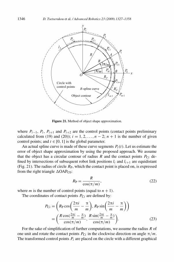
Figure 21. Method of object shape approximation.
where Pi−1, Pi , Pi+1 and Pi+2 are the control points (contact points preliminarycalculated from (19) and (20)); i = 1,2, . . . , n − 2; n + 1 is the number of givencontrol points; and t ∈ [0,1] is the global parameter.
An actual spline curve is made of these curve segments Pi(t). Let us estimate theerror of object shape approximation by using the proposed approach. We assumethat the object has a circular contour of radius R and the contact points PCi de-fined by intersections of subsequent robot link positions li and li+1 are equidistant(Fig. 21). The radius of circle RP, which the contact point is placed on, is expressedfrom the right triangle �OAPC0:
RP = R
cos(π/m), (22)
where m is the number of control points (equal to n + 1).The coordinates of contact points PCi are defined by:
PCi =(
RP cos
(2πi
m− π
m
),RP sin
(2πi
m− π
m
))
=(
R cos(2πim
− πm
)
cos(π/m),R sin(2πi
m− π
m)
cos(π/m)
). (23)
For the sake of simplification of further computations, we assume the radius R ofone unit and rotate the contact points PCi in the clockwise direction on angle π/m.The transformed control points Pi are placed on the circle with a different graphical
D. Tsetserukou et al. / Advanced Robotics 23 (2009) 1327–1358 1347
scale for geometrical visualization (numerical value of R′P is equal to RP). Cartesian
coordinates of control points can be calculated from:
Pi =(
cos(2πim
)
cos(π/m),
sin(2πim
)
cos(π/m)
), (24)
where i = 0,1, . . . ,m − 1.The worst approximation is obtained midway between the control points, i.e.,
Pi(0.5). The midpoint of a cubic segment, however, is easily derived from (21) as:
PM = P1(0.5) = 1
48(Pm−1 + 23P0 + 23P1 + P2). (25)
After substitution of the control point coordinates from (24) to (25) we have:
PM =(
(1 + cos θ)(11 + cos θ)
24 cos(θ/2),
sin θ(11 + cos θ)
24 cos(θ/2)
), (26)
where θ = 2π/m.The deviation E (%) from a true circle is expressed as:
E = (1 −
√P 2
M
) × 100 = 1 − cos(2π/m)
12× 100. (27)
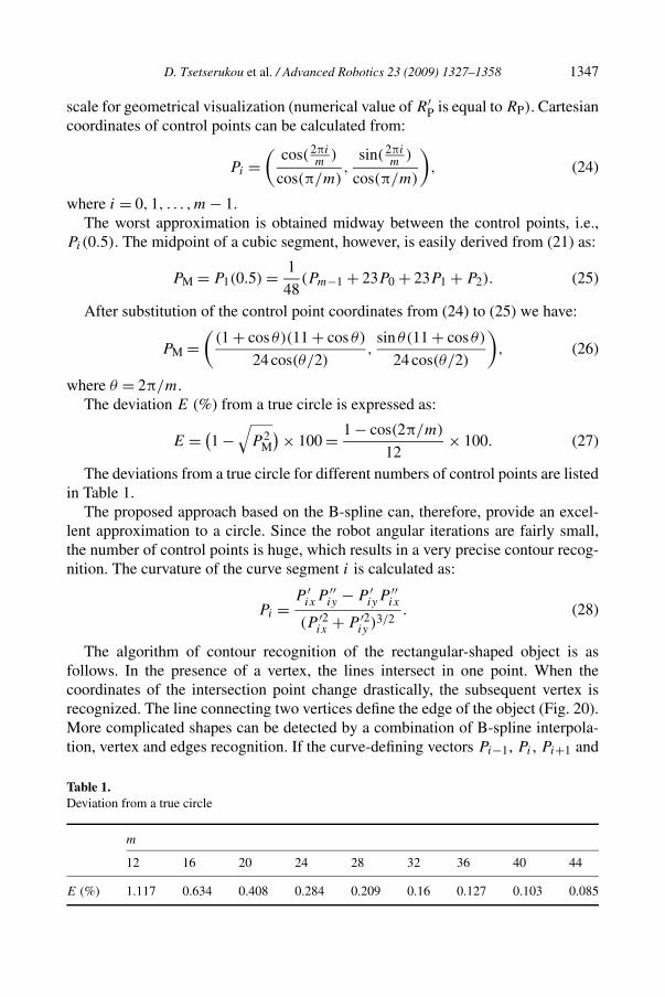
The deviations from a true circle for different numbers of control points are listedin Table 1.
The proposed approach based on the B-spline can, therefore, provide an excel-lent approximation to a circle. Since the robot angular iterations are fairly small,the number of control points is huge, which results in a very precise contour recog-nition. The curvature of the curve segment i is calculated as:
Pi = P ′ixP
′′iy − P ′
iyP′′ix
(P ′2ix + P ′2
iy )3/2. (28)
The algorithm of contour recognition of the rectangular-shaped object is asfollows. In the presence of a vertex, the lines intersect in one point. When thecoordinates of the intersection point change drastically, the subsequent vertex isrecognized. The line connecting two vertices define the edge of the object (Fig. 20).More complicated shapes can be detected by a combination of B-spline interpola-tion, vertex and edges recognition. If the curve-defining vectors Pi−1, Pi , Pi+1 and
Table 1.Deviation from a true circle
m
12 16 20 24 28 32 36 40 44
E (%) 1.117 0.634 0.408 0.284 0.209 0.16 0.127 0.103 0.085

1348 D. Tsetserukou et al. / Advanced Robotics 23 (2009) 1327–1358
Pi+2 lie collinear, the curve segment defined by those four position vectors degener-ates to a line segment. This line segment connects continuously to the neighboringcurve segments with continuity up to the curvature vector. This feature is extremelyuseful in the case of complex shape recognition.
4.6. Estimation of Contacting Object Stiffness
During the first stage of control the robot links rotate until one of them contacts theobject. The control system detects the contact state using the reference and actualtorque values in the joints.
During contact transition we can acquire information about the collision dangerof contacting the object through its stiffness estimation and represent this infor-mation to the operator. This can be done by establishing stiff contact through PDcontrol of the robot arm with high P-gain until the joint torque exceeds the thresh-old value of 0.05 Nm. The robot was commanded to follow the trajectory in freespace with a constant angular velocity. An object was placed on this path so thatthe second link would contact it. The joint torque was recorded for the fourth jointwhile contacting with object. Figure 22a–e shows experimental results when thelink comes into contact with objects having different stiffness varying from a verylow rate to a very high, i.e., a piece of sponge, rubber sponge, rubber, chemicalwood and aluminum, respectively. The time derivative of the torque during impactis given in Fig. 22f.
It is apparent from the plots presented in Fig. 22 that the stiffer the contactingobject, the smaller the angle of robot joint rotation. The elastic deformation of theobject and inherent compliance of robot joints lead to rotation of the robot arm byangle �θi during contact transience (Fig. 23).
The proposed method of estimation of contacting object stiffness is based onthe principles of solid mechanics for an elastic linear material model. It includesthe following stages: (i) calculation of the total elastic deformation of robot linkwith object δi , (ii) estimation of the total stiffness of a robot link–object pair ki ,and (iii) computation of the object stiffness ko from the given values of the robotlink stiffness and total stiffness. The given data are contact point coordinates PCi
(derived from (19) and (20)), the changes in joint angle �θi and joint torque value�τi while colliding (�θi and �τi are derived from Fig. 22).
The distance that contact point C on the robot link surface 1 moves perpendic-ularly to the radius ri under torque �τi , is equal to ri�θi (since the angle �θi
is fairly small). The unknown angle ϕi can be found by taking into account that� C′CB = � OCA = ϕi :
ϕi = arctan
(OA
CA
)= arctan
(hi
PCi
), (29)
where hi equals half of the robot link thickness.The total elastic deformation is calculated from the right triangle �CBC′ as:
δi = �θiri cos(ϕi). (30)

D. Tsetserukou et al. / Advanced Robotics 23 (2009) 1327–1358 1349
(a) (b)
(c) (d)
(e) (f)
Figure 22. Experimental results of stiffness estimation.
The radius of the contact point trajectory ri is found as ri =√
P 2Ci
+ h2i through
consideration of the right triangle �CAO.

1350 D. Tsetserukou et al. / Advanced Robotics 23 (2009) 1327–1358
Figure 23. Scheme for elastic deformation calculation.
Table 2.Findings from the experimental diagrams
Parameter Sponge Rubber sponge Rubber Wood
�θi10−4 (rad) 39.53 10.82 4.12 3.84�τi10−2 (Nm) 2.98 3.0 2.79 2.92
Now, we can easily calculate the total stiffness:
ki = Fni
δi
= �τi
PCi�θiri cos(ϕi)
= �τi
PCi�θi
√P 2
Ci+ h2
i cos(arctan(hi/PCi))
. (31)
By linear approximation, we take into account only two values of θi for τi nearestto 0.02 and 0.05 Nm. Then, from the experimental diagrams (Fig. 22a–e) we obtain�θi , and �τi and list them in Table 2.
The total elastic deformation δi is made up of elastic deformation caused byobject compliance δo and that generated by joint flexibility δri . That is, we canwrite:
δi = Fni
ki
= δo + δri = Rni
ko+ Fni
kri, (32)
where Rni is the reaction, the absolute value of which equals Fni ; ko and kri are thestiffness of the object and the stiffness of the robot link, respectively.
The coefficient kri is mainly defined by torque sensor stiffness, harmonic drivestiffness, structural flexibility and P-gain magnitude. Detailed examination hasshowed that a complex theoretical model of robot link stiffness can hardly provideaccurate estimation of kri . Therefore, we can set the value of robot link stiffness

D. Tsetserukou et al. / Advanced Robotics 23 (2009) 1327–1358 1351
Table 3.Total stiffness and object stiffness
Parameter Sponge Rubber sponge Rubber Wood
ki (N/m) 260.84 959.3 2343.78 2469.04ko (N/m) 282.04 1325.92 7223.94 8562.90
close to the total stiffness in the hardest contact case. This assumption is validbecause during impact with a hard environment, such as the aluminum plate, thecontact deformation of the object is too small to be accounted for (ko ≈ ∞). Thus,using (29)–(31) and the data presented in Fig. 22a–e we derive the unknown valueof kri :
kri = 0.0293 Nm
0.175 · 2.758 · 10−4 · 0.1776 · 0.986 m2= 3468.6
N
m.
The stiffness of the objects is calculated from:
ko = kri · ki
kri − ki
, (33)
where ki is defined by (31). Derived values of the total stiffness ki and object stiff-ness ko are given in Table 3.
The obtained results demonstrate a strong correspondence of correlation amongthe calculated object stiffness with that of real objects. Naturally, the actual stiff-ness of the colliding environment differs from the calculated one with finite error.To achieve high accuracy, specific equipment is needed. However, our aim was onlyassessment of the danger level of robot arm collision with an object. Specifically,we can define that sponge and rubber sponge material are safe for interaction, butrubber, wood and metal pose a threat while striking the robot arm. Consequently,we have succeeded in solving the main task — object classification by getting in-formation about stiffness during impact.
In the case when the collision must be detected robustly without considerationof object properties, the value of the time derivative of torque can be used to judgethe impact value (Fig. 22f).
4.7. Experimental Results of Obstacle Avoidance Through Haptic Interaction andAccomplishment of Human Motion Following
The still images of the robot arm motion video are given in Fig. 24.The robot arm is controlled by the program on a Dell Precision computer (CPU:
Intel Pentium, 3.2 GHz, memory 2 GB). The results show that the robot arm slidesover the obstacle surface (black object on the table) smoothly and maintains con-stant physical contact with it till the end-effector reaches the target point. The speedof the obstacle avoidance can be adjusted online depending on the object properties

1352 D. Tsetserukou et al. / Advanced Robotics 23 (2009) 1327–1358
Figure 24. Experiment of obstacle avoidance through whole-arm tactile interaction.
Figure 25. Experiment of human-following motion.
and shape. For example, a shape composed of edges and vertices can be handledfaster than one with curve contour.
The remarkable opportunity of ensuring safe robot–environment interaction isthat we can establish different dynamic parameters of the robot arm contacting withthe environment according to the calculated object stiffness (by using the methoddescribed in Section 4.6). This is an inherent capability of humans, since when wecollide with stiff objects we tend to soften our muscles as much as we can.
In order to verify the ability of the developed robot arm iSoRA to safely inter-act with human beings along the entire surface and to perform cooperative tasksthrough human-following motion, the experiment was conducted. In the first stageof interaction, force was applied to the upper arm of the humanoid robot arm. Therobot arm generates compliant motion according to the applied force value andcomes to the position shown in Fig. 25 (left). Then, an additional force was applied

D. Tsetserukou et al. / Advanced Robotics 23 (2009) 1327–1358 1353
to the forearm of iSoRA. Since the net torque has a counter-clockwise direction atthe pitch joint of the shoulder, the robot arm generates continuous compliant motionupward (Fig. 25, right).
It can be seen from Fig. 25 that the elaborated intelligent joint admittance controlenables the human cooperating with the service robot to control the position andorientation of the robot arm through haptic interaction along the entire robot armsurface. The robot successfully recognizes the human-following task and generatescompliant motion in a safe manner.
4.8. Application of a Robot with a Tactile-Sensitive Robot Arm
The proposed concept opens a wide range of potential applications in service ro-botics and teleoperation. Here, we discuss other possible applications of the robotarm with whole-arm tactile sensing ability.
The obstacle avoidance presents significant issues for urban search and rescuerobots. Such robots aim at assisting rescue workers in the investigation of unreach-able areas, such as small cracks and pipes, or unsafe places by delivering visualinformation from cameras at the end-effector. Controllable compliance of the robotarm joint can be extremely useful in this application, since it provides whole-armtactile interaction with the environment. Therefore, such type of manipulator hassignificant capabilities for performance improvement in comparison with conven-tional manipulators in the field of obstacle avoidance. We summarize possible casesof application of the robot enabling intelligent tactile obstacle avoidance as follows:
(i) A robot arm finds the path through interaction with obstacles in extremelycramped environments (Fig. 18).
(ii) A robot reaches for a visible object located inside a narrow space. The robotarm contacts and follows the surface of the obstacle represented by the sidesof the box to fulfill the task (Fig. 26).
(iii) A robot reaches for an object located beyond the robot camera visibility range.In such cases the robot arm needs to be equipped with additional cameras inorder to process the collision softly on its own (Fig. 27).
Figure 26. Robot reaches the object located in narrow space.

1354 D. Tsetserukou et al. / Advanced Robotics 23 (2009) 1327–1358
Figure 27. Robot reaches the object located beyond visibility range.
Figure 28. Robot investigates the indoor environment.
(iv) A robot investigates the indoor area to achieve situational awareness withoutthe necessity of its bulky body entering the room. When the situation is as-sessed, the robot body can elude the jamb and enter into the room carefully(Fig. 28).
(v) A robot structures the environment. A vision system of conventional robotscannot determine the distance to the object in three-dimensional space. By tac-tile interaction, the robot can precisely define the object location and reachableworking area.
The developed robot and proposed algorithms can enable a service robot not onlyto work in a dynamic unstructured environment, but also to cooperate with humansin a safe manner and to assist rescue workers in the investigation of unreachableplaces.
D. Tsetserukou et al. / Advanced Robotics 23 (2009) 1327–1358 1355
5. Conclusions and Future Work
A new whole-sensitive robot arm, iSoRA, was developed to provide human-like ca-pabilities of performing contact tasks in a broad variety of environments. Each jointwas facilitated with a high-performance optical torque sensor. Intelligent variableadmittance control and reflex action-based impact control were elaborated to realizesafe, smooth and natural human–robot interaction. We introduced the exponentialfunctional dependency between the sensed force and stiffness to impart human-likedamping and stiffness behavior to the robot arm. Experimental results of impact re-vealed that large contact forces, mainly used as criteria of collisions, do not indicatethe impact state, while the time derivative of the force value does. The magnitude oftime derivative of torque was used as an indicator of the collision state. To realize re-flexive human-like behavior, the stiffness of the impedance model of the robot armwas reduced drastically during the collision transient. This was achieved by meansof the reciprocal functional dependency of stiffness on the value of the time deriva-tive of the torque. The effectiveness of the controllers was experimentally illustratedon the whole-sensitive robot arm. The conventionally impedance-controlled robotcan provide contacting task only at the tip of the end-effector with predetermineddynamics. By contrast, approaches developed by us provide delicate continuoussafe interaction of all surface of the robot arm with the environment.
The proposed concept of obstacle avoidance through whole-arm tactile interac-tion enables the manipulator to adapt the planned motion to the obstacle shape. Suchan algorithm is especially valuable for service robots working in real indoor envi-ronments. Tactile interaction gains the essential information about the contactingobject (shape, stiffness, location, etc.). Numerical simulation revealed that the de-scribed method for object shape recognition based on the B-spline approximationprovides high accuracy of contour approximation. The method of object stiffnessestimation is presented and verified. The experimental results presented show thevalidity and robustness of the proposed concept. Our approach can also be extendedfor object shape recognition and motion planning in three-dimensional space.
The subject of ongoing work is to adapt the dynamic parameters of the robotto the surface properties (stiffness, friction coefficient) of the contacting object.Object mobility and object fixation will be examined by observing the externalforce pattern during physical interaction.
Acknowledgements
The research is supported in part by a Japan Society for the Promotion of SciencePostdoctoral Fellowship for Foreign Scholars.
References
1. T. Lozano-Perez, A simple motion-planning algorithm for general robot manipulators, IEEE J.Robotics Automat. 3, 224–238 (1987).

1356 D. Tsetserukou et al. / Advanced Robotics 23 (2009) 1327–1358
2. T. Yoshikawa, M. Koeda and H. Fujimoto, Shape recognition and grasping by robotic hands withsoft fingers and omnidirectional camera, in: Proc. IEEE Int. Conf. on Robotics and Automation,Pasadena, CA, pp. 299–304 (2008).
3. V. J. Lumelsky, M. S. Shur and S. Wagner, Sensitive skin, IEEE Sensors J. 1, 41–51 (2001).4. V. Lumelsky and E. Cheung, Towards safe real-time robot teleoperation: automatic whole-
sensitive arm collision avoidance frees the operator for global control, in: Proc. IEEE Int. Conf.on Robotics and Automation, Sacramento, pp. 797–802 (1991).
5. J. T. Feddema and J. L. Novak, Whole arm obstacle avoidance for teleoperated robot, in: Proc.IEEE Int. Conf. on Robotics and Automation, San Diego, CA, pp. 3303–3309 (1994).
6. S. Morikawa, T. Senoo, A. Namiki and M. Ishikawa, Real-time collision avoidance using a ro-bot manipulator with light-weight small high-speed vision system, in: Proc. IEEE Int. Conf. onRobotics and Automation, Rome, pp. 794–799 (2007).
7. F. Caccavael, C. Natale, B. Siciliano and L. Villani, Six-DOF impedance control based on an-gle/axis representation, IEEE Trans. Robotics Automat. 15, 289–300 (1999).
8. H. Iwata, S. Kobashi, T. Aono and S. Sugano, Design of anthropomorphic 4-DOF tactile inter-action manipulator with passive joints, in: Proc. IEEE/RSJ Int. Conf. on Intelligent Robots andSystems, Edmonton, pp. 1785–1790 (2005).
9. A. Bicchi and G. Tonietti, Fast and soft arm tactics: dealing with the safety-performance trade-offin robot arms design and control, IEEE Robotics Automat. Mag. 11, 22–33 (2004).
10. G. Hirzinger, A. Albu-Schaffer, M. Hahnle, I. Schaefer and N. Sporer, On a new generation oftorque controlled light-weight robots, in: Proc. IEEE Int. Conf. on Robotics and Automation,Seoul, pp. 3356–3363 (2001).
11. N. Mitsunaga, T. Miyashita, H. Ishiguro, K. Kogure and N. Hagita, Robovie IV: a communicationrobot interacting with people daily in an office, in: Proc. IEEE/RSJ Int. Conf. Intelligent Robotsand Systems, Beijing, pp. 5066–5072 (2006).
12. D. Tsetserukou, R. Tadakuma, H. Kajimoto and S. Tachi, Optical torque sensors for local im-pedance control realization of an anthropomorphic robot arm, J. Robotics Mechatron. 18, 121–130(2006).
13. D. Tsetserukou and S. Tachi, Torque sensors for robot joint control, in: Sensors, Focus on Tactile,Force and Stress Sensors, J. G. Rocha and S. Lanceros-Mendes (Eds), pp. 15–36. Austria (2008).
14. N. Hogan, Impedance control: an approach to manipulation, Part I–III, ASME J. of Dyn. Syst.Meas. Control. 107, 1–23 (1985).
15. R. Carelli and R. Kelly, Adaptive impedance/force controller for robot manipulators, IEEE Trans.Automatic Control. 36, 967–972 (1991).
16. R. V. Dubey, T. F. Chang and S. E. Everett, Variable damping impedance control of a bilateraltelerobotic system, IEEE Control Syst. Mag. 17, 37–44 (1997).
17. T. Tsumugiwa, R. Yokogawa and K. Hara, Variable impedance control based on estimation ofhuman arm stiffness for human–robot cooperative calligraphic task, in: Proc. IEEE Int. Conf.Robotics and Automation, Washington, DC, pp. 644–650 (2002).
18. D. P. Ferris and C. T. Farley, Interaction of leg stiffness and surface stiffness during human hop-ping, J. Appl. Physiol. 82, 15–22 (1997).
19. M. M. Rahman, R. Ikeura and K. Muzutani, Investigating the impedance characteristics of humanarm for development of robot to cooperate with human operators, in: Proc. IEEE Int. Conf. onSystems, Man and Cybernetics, Tokyo, pp. 676–681 (1999).
20. I. D. Walker, Impact configuration and measures for kinematically redundant and multiple armedrobot system, IEEE Trans. Robotics Automat. 10, 670–683 (1994).

D. Tsetserukou et al. / Advanced Robotics 23 (2009) 1327–1358 1357
21. R. Volpe and P. Khosla, A theoretical and experimental investigation of impact control for manip-ulators, Int. J. Robotics Res. 12, 351–365 (1993).
22. J. Bauer, Mobile robot with tactile arm used for exploration and pushing tasks, in: Proc. IEEE/RSJInt. Conf. on Intelligent Robots and Systems, Osaka, pp. 560–567 (1996).
23. A. M. Okamura, M. L. Turner and M. R. Cutkosky, Haptic exploration of objects with rollingand sliding, in: Proc. IEEE Int. Conf. on Robotics and Automation, Albuquerque, pp. 2485–2490(1997).
24. S. Caselli, C. Magnaninni, F. Zanichelli and E. Caraffi, Efficient exploration and recognition ofconvex objects based on haptic perception, in: Proc. IEEE Int. Conf. on Robotics and Automation,Minneapolis, MN, pp. 3508–3515 (1996).
25. A. S. Rao and K. Y. Goldberg, Shape from diameter: recognizing polygonal parts with a parallel-jaw gripper, Int. J. Robotics Res. 13, 16–37 (1994).
26. M. Kaneko, H. Maekawa and K. Tanie, Active tactile sensing by robotic fingers based onminimum-external-sensor-realization, in: Proc. IEEE Int. Conf. on Robotics and Automation,Nice, pp. 1289–1294 (1992).
27. R. L. Klatzky and S. Lederman, Intelligent exploration by the human hand, in: Dexterous Ro-bot Manipulation, S. T. Venkataraman and T. Iberall (Eds), pp. 66–81. Springer, New York, NY(1990).
28. F. Yamaguchi, Curves and Surfaces in Computer Aided Geometric Design. Springer-Verlag,Berlin (1988).
About the Authors
Dzmitry Tsetserukou received the BS degree with honors in Electrical Engineer-ing from the Mogilev Machine Building Institute, Belarus, in 1999, the MS degreein Mechanical Engineering from the National Academy of Sciences of Belarus, in2002, and the PhD degree in Information Science and Technology from the Uni-versity of Tokyo, Japan, in 2007. From 2002 to 2004, he was a Research Associatein the scientific research group at the National Academy of Sciences of Belarus.He is currently a JSPS Post-Doctoral Fellow in the Department of InformationPhysics and Computing at the University of Tokyo, Japan. He is a member of the
IEEE and the author of over 50 technical publications, three patents, a book chapter and a book. Hisresearch interests include humanoid robots, force/torque sensors, impedance and admittance control,teleoperation, haptic interfaces and displays, and affective haptics.
Naoki Kawakami received the MS and PhD degrees from the University ofTokyo, Japan, in 1996 and 1999, respectively. He is currently a Lecturer in the De-partment of Information Physics and Computing at the University of Tokyo. Hisresearch interests include virtual reality, real-time remote robotics, telexistenceand retro-reflective projection technology. He is the author of over 150 technicalpublications.

1358 D. Tsetserukou et al. / Advanced Robotics 23 (2009) 1327–1358
Susumu Tachi received his BS, MS and PhD degrees from the University ofTokyo, in 1968, 1970 and 1973, respectively. From 1975 to 1989, he was a Direc-tor of the Biorobotics Division at the Mechanical Engineering Laboratory, Min-istry of International Trade and Industry, Tsukuba Science City, Japan. From 1989to 2009, he was a Professor in the Department of Information Physics and Com-puting, University of Tokyo. He is currently a Professor in the Graduate School ofMedia Design, Keio University, Japan. He is a Founding Director of the RoboticSociety of Japan and a Founding President of the Virtual Reality Society of Japan.
From 1988, he has served as a Chairman of the IMEKO (International Measurement Confederation)Technical Committee on Measurement in Robotics. He is a member of IEEE VR Steering Committee,and has served as a General Chair of IEEE VR 2001 and 2002. He was responsible for the followingresearch projects: Guide Dog Robot (1976–1983), National Large Scale Project on Advanced Robot-ics in Hazardous Environment (1983–1990), National Large Scale Project on Humanoids and HumanFriendly Robotics (1998–2003), and CREST Project on Telexistence Communication Systems (2000–2005). He is the author of over 500 technical publications. His research interests include virtual reality,real-time remote robotics, telexistence and retro-reflective projection technology.