ISOLED FLEX III OPERATIONAL / SERVICE MANUAL
18
1 ISOLED FLEX III OPERATIONAL / SERVICE MANUAL
Transcript of ISOLED FLEX III OPERATIONAL / SERVICE MANUAL

1
ISOLED FLEX III
OPERATIONAL / SERVICE MANUAL

2
IsoLED FLEX III CUSTOMER MANUAL
Document No. OM-1231-C
Version 1.0
AUGUST 19, 2015
ISOLUX LLC
1045 Collier Center Way Suite 6
Naples FL, 34110
3
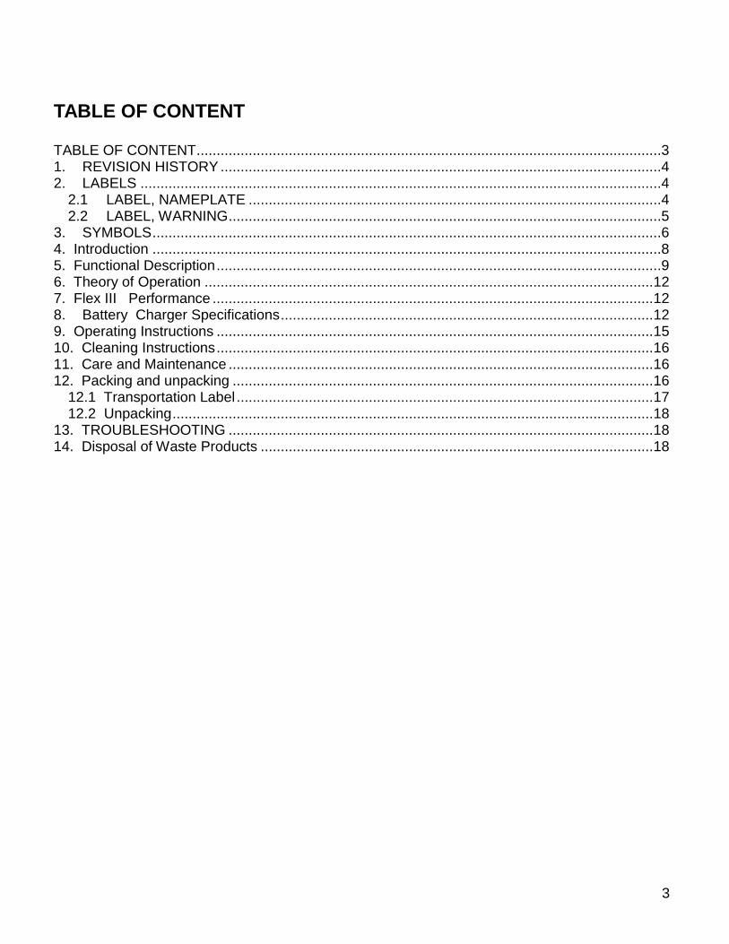
TABLE OF CONTENT TABLE OF CONTENT ....................................................................................................................3
1. REVISION HISTORY ..............................................................................................................4 2. LABELS ..................................................................................................................................4
2.1 LABEL, NAMEPLATE .......................................................................................................4 2.2 LABEL, WARNING ............................................................................................................5
3. SYMBOLS ...............................................................................................................................6
4. Introduction ...............................................................................................................................8 5. Functional Description ...............................................................................................................9 6. Theory of Operation ................................................................................................................ 12 7. Flex III Performance .............................................................................................................. 12
8. Battery Charger Specifications ............................................................................................. 12 9. Operating Instructions ............................................................................................................. 15
10. Cleaning Instructions ............................................................................................................. 16 11. Care and Maintenance .......................................................................................................... 16
12. Packing and unpacking ......................................................................................................... 16 12.1 Transportation Label ........................................................................................................ 17 12.2 Unpacking ........................................................................................................................ 18
13. TROUBLESHOOTING .......................................................................................................... 18 14. Disposal of Waste Products .................................................................................................. 18

4
1. REVISION HISTORY
Version Release Date Comments
0.1 11/13/2013 Rough Draft
1.0 08/19/2015 Final Document
2. LABELS
2.1 LABEL, NAMEPLATE
ISOLUX LLCNAPLES, FL. USA
LED PORTABLE DIAGNOSTIC LAMP
MODEL No: IsoLED Flex III
S/N: XXXXX
INPUT
16.8 VDC @ 0.9 A
15.1 watts max.
OUTPUT
Optical Output: >50 Klux @ 0.5 m
Operating Temp.: 0 to 50 C
Storage Temp.: -10 to 60 C
BATTERY OPERATED
14.4 VDC - 4 hours operation
@ full intensity
Material: 1. Transparent Gloss Polyester with permanent Acrylic Adhesive backing. 2. Background color: Transparent.
3 .Lettering and Markings: Black. 4. Size: 3.00” by 1.00”

5
2.2 LABEL, WARNING
Read accompanying documents
ISOLUX LLC Naples, FL. USA
Transport should only be undertaken with the light head facing directly
down with the gooseneck arm bent over as close as possible to itself.
Transport ne doit être entrepris avec la tête de lampe directement face vers
le bas avec le col de cygne bras pliés au plus près possible de lui-même
Material: 1. Transparent Gloss Polyester with permanent Acrylic Adhesive backing. 2. Background color: Transparent.
3 .Lettering and Markings: Black. 4. Size: 3.00” by 1.50”

6
Notes:
1. Unit is designed with protection against electric shock as per the requirements of IEC 60601
2. Equipment is not suitable for use in the presence of a flammable anaesthetic mixture with air or with oxygen or nitrous oxide.
3. SYMBOLS
QPS LISTING MARKING
Caution
Protective Earth Ground
Read accompanying documents

7
Temperature Range: Operating, Storage and Transportation
Relative Humidity Range
This Side Up
Keep Dry
Recycle

8
4. Introduction The IsoLED Flex III is a portable, battery operated Exam / Diagnostic lamp ideal for use in the following environments:
OB/GYN
FAMILY PRACTICE
DERMATOLOGY
EMERGENCY ROOMS
OUTPATIENT FACILITIES
LABOR 7 DELIVERY SETTINGS
URGENT CARE CENTERS It’s portability without the encumbrance of a power cord and the flexibility of its gooseneck allows it to be used anywhere at any position. Its high efficiency design allows for reduced energy consumption and reduced cost of ownership, while its 50,000 hour of LED life provides for a free maintenance device with and end life of around 20 years. Its design follows and surpass the Energy Star Requirements
Its CRI of 95 rating produces a very high color rendition for accurate diagnosis; and the life of the LEDs used is kept high by limiting their junction temperature to less than 45 º C for a better than 50,000 hours of operation; while its meager power consumption of 10.5 watts provides for a very efficient and eco-friendly lamp.
The IsoLED Flex III lamp has been designed taking into account all of the different disciplines that makes up for true latest-state-of-the-art LED technologies:
Efficiency The LED Driver Board has an efficiency of 76 % and delivers 9 watts to power the unit’s three LEDs. The battery charger efficiency is greater than 80 % and its Hi-Pot insulation is >4,000 VAC for 1 minute.
Color Rendition Index Typical CRI of 95 for excellent color rendition.

9
llumination The LED optical efficiency plus the optical efficacy of the secondary optics used, provides > 100,000 lux at 12 inches from source, for a Figure of Merit of 9500 lux/watt Thermal The thermal design has been designed around keeping the Junction temperature of the LEDs lower than 45 º C (for a 27 º C ambient). This ensures the long life of 50,000 hours (70% of max.) and the minimum decrease of the lamp’s illuminance vs. time.
5. Functional Description . The unit’s front panel and interconnect diagram are depicted in Figure 5.1. The Control Box
diagram is depicted in Figure 5.2. The IsoLED Flex III unit consists of three (3) major components: The Control Box, The Headlight Assembly and the Battery Charger. All of the electronics are housed in the Control Box including the unit’s two controls and two displays located at its front panel:
Brightness Control: Controls the light intensity from 3 % to 100 %.
Power ON Switch: Turns the unit on or off.
Power ON indicator: Shows unit’s status, on or off.
Low Battery Indicator: Warns the operator that the battery is low The Control Box houses the 4-cell Battery Pack and the LED Driver. The Headlight Assembly contains the unit’s Light Engine, composed of three LEDs, heat sink, optics, 10 K thermistor and Metal Clad PC Board. The unit’s battery charger is a Medical Approved unit certified to UL60601-1, EN60950, EN60601-1, EN60335-2-29 and is also certified to the following EMC Standards: EN60601-1-2, EN61000-6-3 (Emission) and EN61000-6-1 (Immunity). See Figure 11.1: Battery Charger Specifications.

10
l
O
BRIGHTNESS
LO BATT.
POWER ON
CONTROL BOX
Figure 5.1 IsoLED Flex III Interconnect Diagram
BRIGHTNESS
CONTROL
LOW BATTERY
INDICATOR
POWER ON
SWITCH
POWER ON
INDICATOR
CONTROL BOX - Battery Pack - LED Driver
HEADLIGHT - Heat sink - LED - Optics
GOOSENECK
Battery
Charger

11
From Battery
ChargerTo Headlight
4-Cell
Battery
Pack LED DRIVER
UNIT'S CONTROL BOX
Power On
Switch
Brightness
Control
Power On
Indicator
Low Battery
Indicator
FRONT PANEL
Figure 5.2 Control Box Diagram NOTES:
1. The Battery Charger is only used when the unit is charging and non-operative.
2. The maximum voltage in the unit is 14.8 VDC. 3. There is no connection to any AC power source during unit’s operation

12
6. Theory of Operation The Control Box houses the 4-Cell Battery Pack and the LED Driver Board. The Battery Pack, when low, gets charged when the Battery Charger is connected to the DC Jack located at the back of the Control Box. When the battery pack is fully charged, the battery charger indicator turns from red to green. The battery pack 14.4 VDC powers the LED Driver Board, which in turn, provides the 0.8 amps constant current that drives the unit’s three LEDs. The Brightness Control provides a dimming range from 3 to 100 % of full optical power. The Low Battery Indicator turns from green to red when the battery pack voltage drops below 12 VDC.
7. IsoLED Flex II Performance
The unit’s performance is depicted in Figure 7.1: Flex III Specifications.
8. Battery Charger Specifications The unit’s battery charger is a Medical Approved unit certified to UL60601-1, EN60950, EN60601-1, EN60335-2-29 and is also certified to the following EMC Standards: EN60601-1-2, EN61000-6-3 (Emission) and EN61000-6-1 (Immunity). See Figure 8.1: Battery Charger Specifications.

13
Figure 7.1 Flex III Specifications
# of LEDs Three Warm White LEDs
Color Temperature 4000 to 4500 º K
CRI (Color Rendition Index) 95 Typical
Light Intensity @ 0.5 meter > 50, 000 lux
Working Distance 0.5 to 1 meter
Spot Size 8 cm @ 0.5 meter
LEDs Life > 50,000 Hours
Operating Temperature 10 º C to +40 º C
Electrical Power
14.4 volts Battery Pack (4 x 3.7 cells) rechargeable ion lithium batteries – 2.6 A-Hour Capacity
Minimum Operating Time
4 hours of continuous operation at maximum light intensity.
Power Consumption 10.5 watts
Efficiency Meets Energy Star Guidelines
Dimming 3 % to 100 %
Controls:
- On/Off power switch - Power On green indicator - Low Battery green / red indicator - Brightness Control
Battery Charger, 15.1 watts Universal AC Input
- UL certified per IEC 60601-1, 1988, 2nd edition.
Weight 12.9 lbs

14
Figure 8.1 Battery Charger Specifications
AC Input Voltage Range Universal: 100 to 240 VAC
Input Frequency 47 to 63 Hz.
Efficiency 80 %
Charge Current 0.9 A, ± 5 %
Charge Voltage 16.8 ± 0.1 VDC
Terminal Charge 0.1 A ± 25 %
Output Power 15.1 watts
Ripple < 100 mV p-p
Operating Temperature -25 °C to +40°C
Insulation Class Class II
Insulation Voltage 4,000 VAC (primary) / 5,640 VDC (secondary)
Electrical Safety Approvals UL60601 – 1, EN60950, EN60601-1, EN60335-2-29
EMC Standards EN60601-1-2, EN61000-6-3 (Emissions), EN61000-6-1 (Immunity)
Reliability (MIL-GDBK-217F) MTBF > 250,000 hours at 30 °C and full load
Dimensions 4” x 1.8” x 1.5”
Weight 0.29 lbs

15
9. Operating Instructions
The IsoLED Flex III battery operated unit is an ambulatory unit that could be moved to any location by means of its 5 – wheel base; in addition, It’s extremely flexible arm (gooseneck) allows it to be positioned at any angle and distance from the patient. The operation of the IsoLED Flex III unit is simplicity on itself:
- Turn power ON and observe the unit’s brightness, turning the brightness control clockwise
increases the light intensity. At full brightness, the battery pack will last approximately 4 hours.
- Low battery indicator will turn from green to red when the battery voltage has decreased to < 12 VDC. When that happens, move the unit to its charging station and plug the battery charger to its DC jack located at the back of the Control Box. The charging time will be around 3 hours (overnight charge)
16
10. Cleaning Instructions
Overall appearance - Check the general aesthetics of the IsoLED Flex III Diagnostics Lamp. The unit should be kept clean and dust free. Clean and dust as necessary.
Optical Window - The front lens is made from a UV resistant polycarbonate plastic that has an external hard coating to resist scratching. Clean the lens using glass/plastic cleaner or mild soap and water mix. It is very important to use a clean, soft cloth to avoid any scratching of the lens. Never spray the cleaning fluid directly onto the lens surface, but instead spray into clean cloth and then wipe the lens. Do not expose the unit to excessive moisture. Failure to do so could result in personal injury and/or property damage.
11. Care and Maintenance Unit does not require any special handling. The only maintenance required is to wipe the unit’s window with a soft non-lint cloth as required with its use (as needed). Unit should perform to over 50,000 hours with a minimum 70 % degradation of its light output. If unit fails to turn on, send back to factory for repairs.
The IsoLED Flex III will give you years of failure free performance and no maintenance cost except for the meager 10.5 watts of power consumed, for a very low cost of ownership. The battery pack, after many recharge cycles (>800) may require replacement. Unit should be sent to Isolux LLC to replace the battery pack.
12. Packing and unpacking The Isolux LLC packing label shows three symbols depicting the environmental ranges of the unit under transportation. The additional four symbols relates to the conditions required for shipping the unit.
Special care should be exercised when transporting the Flex III as per warning label on the back of the Control Unit. Unit shall be packaged with the head light and gooseneck bent tightly together and the head light facing down into the bottom of the container.

17
12.1 Transportation Label
Material: 1. Transparent Gloss Polyester with permanent acrylic adhesive backing.
2. Background color: White 3. Lettering and Markings: Black.
4. Size: 4.00” High by 3.00” Wide
TEMPERATURE
HUMIDITY
ATMOSPHERIC
PRESSURE
FRAGILE THIS SIDE UP KEEP DRY RECYCLE
- 10 C to + 70 C
10 % to 90 %
500 hPa - 1060 hPa

18
12.2 Unpacking WHEN REMOVING PARTS FROM THE SHIPPING CARTONS, BE CAREFUL NOT TO DAMAGE THE COMPONENTS. IMPORTANT: THOROUGHLY CHECK EACH BOX FOR PARTS THAT MAY BE LOCATED IN AREAS THAT CAN BE OVERLOOKED.
13. TROUBLESHOOTING ONLY FACILITY AUTHORIZED MAINTENANCE PERSONNEL SHOULD TROUBLESHOOT THE ISOLED FLEX III SYSTEM. TROUBLESHOOTING BY UNAUTHORIZED PERSONNEL COULD RESULT IN PERSONAL INJURY AND/OR PROPERTY DAMAGE AND COULD VOID WARRANTY.
14. Disposal of Waste Products NO WASTE PRODUCTS ARE PRODUCED BY THE ISOLED FLEX III DIAGNOSTIC LAMP. THE UNIT IS COMPOSED OF NON-TOXIC MATERIALS AND COULD BE DISPOSED OF IN A STANDARD WAY AT THE END OF ITS LIFE.