ISM to Accompany Electric Machinery and Power System ... · This Instructor’s Manual is intended...
337
i Instructor’s Manual to accompany Chapman Electric Machinery and Power System Fundamentals First Edition Stephen J. Chapman BAE SYSTEMS Australia
Transcript of ISM to Accompany Electric Machinery and Power System ... · This Instructor’s Manual is intended...
i
Instructor’s Manual
to accompany
Chapman
Electric Machinery and Power System Fundamentals
First Edition
Stephen J. Chapman BAE SYSTEMS Australia

ii
Instructor’s Manual to accompany Electric Machinery and Power System Fundamentals, First Edition Copyright 2001 McGraw-Hill, Inc. All rights reserved. Printed in the United States of America. No part of this book may be used or reproduced in any manner whatsoever without written permission, with the following exception: homework solutions may be copied for classroom use. ISBN: ???
iii
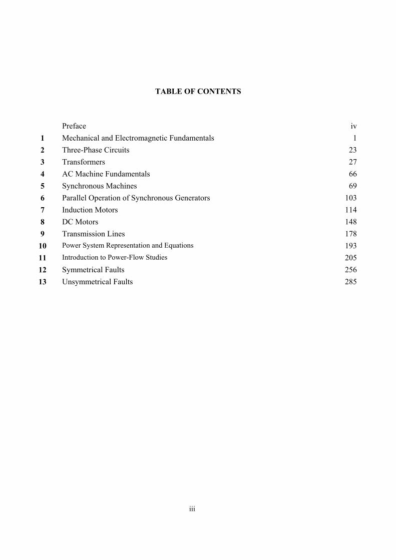
TABLE OF CONTENTS
Preface iv1 Mechanical and Electromagnetic Fundamentals 12 Three-Phase Circuits 233 Transformers 274 AC Machine Fundamentals 665 Synchronous Machines 696 Parallel Operation of Synchronous Generators 1037 Induction Motors 1148 DC Motors 1489 Transmission Lines 178
10 Power System Representation and Equations 19311 Introduction to Power-Flow Studies 20512 Symmetrical Faults 25613 Unsymmetrical Faults 285
iv
PREFACE
TO THE INSTRUCTOR
This Instructor’s Manual is intended to accompany the third edition of Electric Machinery and Power System Fundamentals. To make this manual easier to use, it has been made self-contained. Both the original problem statement and the problem solution are given for each problem in the book. This structure should make it easier to copy pages from the manual for posting after problems have been assigned.
Many of the problems in Chapters 2, 5, 6, and 9 require that a student read one or more values from a magnetization curve. The required curves are given within the textbook, but they are shown with relatively few vertical and horizontal lines so that they will not appear too cluttered. Electronic copies of the corresponding open-circuit characteristics, short-circuit characteristics, and magnetization curves as also supplied with the book. They are supplied in two forms, as MATLAB MAT-files and as ASCII text files. Students can use these files for electronic solutions to homework problems. The ASCII files are supplied so that the information can be used with non-MATLAB software.
The solutions in this manual have been checked carefully, but inevitably some errors will have slipped through. If you locate errors which you would like to see corrected, please feel free to contact me at the address shown below, or at my email address [email protected]. I greatly appreciate your input! My physical and email addresses may change from time to time, but my contact details will always be available at the book’s Web site, which is http://www.mhhe.com/engcs/electrical/chapman/.
Thank you.
Stephen J. Chapman Melbourne, Australia August 16, 2001 Stephen J. Chapman 276 Orrong Road Caulfield North, VIC 3161 Australia Phone +61-3-9527-9372

1
Chapter 1: Mechanical and Electromagnetic Fundamentals
1-1. A motor’s shaft is spinning at a speed of 1800 r/min. What is the shaft speed in radians per second?
SOLUTION The speed in radians per second is
( ) rad/s 5.188r 1rad 2
s 60min 1r/min 1800 =
= πω
1-2. A flywheel with a moment of inertia of 4 kg ⋅ m2 is initially at rest. If a torque of 5 N ⋅ m (counterclockwise) is suddenly applied to the flywheel, what will be the speed of the flywheel after 5 s? Express that speed in both radians per second and revolutions per minute.
SOLUTION The speed in radians per second is:
( ) rad/s 25.6s 5mkg 4mN 5 2 =
⋅⋅=
== t
Jt ταω
The speed in revolutions per minute is:
( ) 1 r 60 s6.25 rad/s 59.7 r/min2 rad 1 min
nπ
= =
1-3. A force of 5 N is applied to a cylinder, as shown in Figure P1-1. What are the magnitude and direction of the torque produced on the cylinder? What is the angular acceleration α of the cylinder?
SOLUTION The magnitude and the direction of the torque on this cylinder is:
CCW ,sinind θτ rF= ( )( ) CCW m,N 607.140 sin mkg 5m 5.0 2
ind ⋅=°⋅=τ
1-4. A motor is supplying 70 N ⋅ m of torque to its load. If the motor’s shaft is turning at 1500 r/min, what is the mechanical power supplied to the load in watts? In horsepower?
SOLUTION The mechanical power supplied to the load is
( )( ) W 000,11r 1rad 2
s 60min 1r/min 1500mN 70 =
⋅== πτωP
( ) hp 7.14W 746
hp 1W 000,11 =
=P
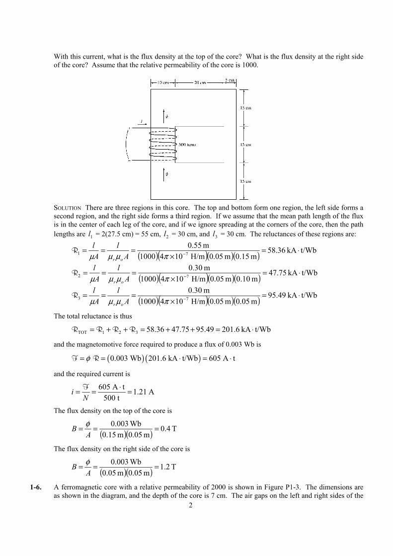
1-5. A ferromagnetic core is shown in Figure P1-2. The depth of the core is 5 cm. The other dimensions of the core are as shown in the figure. Find the value of the current that will produce a flux of 0.003 Wb.
2
With this current, what is the flux density at the top of the core? What is the flux density at the right side of the core? Assume that the relative permeability of the core is 1000.
SOLUTION There are three regions in this core. The top and bottom form one region, the left side forms a
second region, and the right side forms a third region. If we assume that the mean path length of the flux is in the center of each leg of the core, and if we ignore spreading at the corners of the core, then the path lengths are 1l = 2(27.5 cm) = 55 cm, 2l = 30 cm, and 3l = 30 cm. The reluctances of these regions are:
( )( )( )( ) t/WbkA 36.58m 0.15m 05.0 H/m1041000
m 55.071 ⋅=
×=== −πµµµ A
lAl
or
R
( )( )( )( ) t/WbkA 75.47m 0.10m 05.0 H/m1041000
m 30.072 ⋅=
×=== −πµµµ A
lAl
or
R
( )( )( )( ) t/WbkA 49.95m 0.05m 05.0 H/m1041000
m 30.073 ⋅=
×=== −πµµµ A
lAl
or
R
The total reluctance is thus
t/WbkA 6.20149.9575.47 36.58321TOT ⋅=++=++= RRRR
and the magnetomotive force required to produce a flux of 0.003 Wb is
( ) ( ) 0.003 Wb 201.6 kA t/Wb 605 A tφ= = ⋅ = ⋅F R
and the required current is
605 A t 1.21 A
500 ti
N⋅= = =F
The flux density on the top of the core is
( )( ) T 4.0m 0.05m 15.0
Wb 003.0 ===A
B φ
The flux density on the right side of the core is
( )( ) T 2.1m 0.05m 05.0
Wb 003.0 ===A
B φ
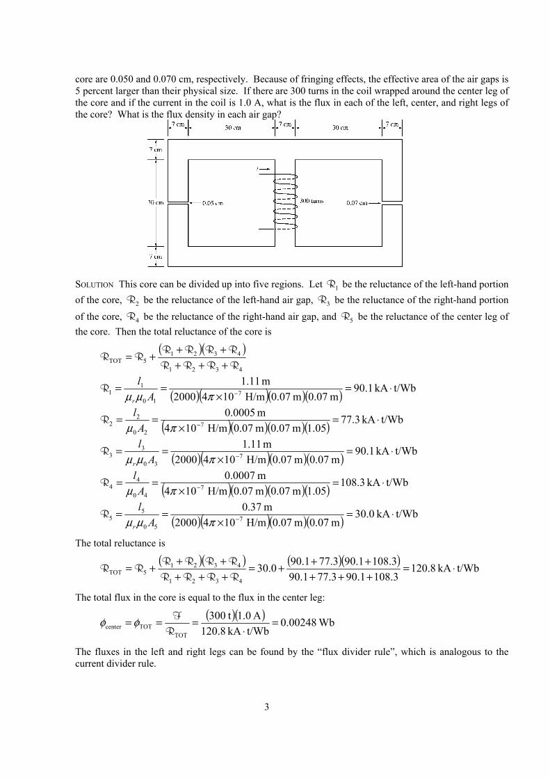
1-6. A ferromagnetic core with a relative permeability of 2000 is shown in Figure P1-3. The dimensions are as shown in the diagram, and the depth of the core is 7 cm. The air gaps on the left and right sides of the
3
core are 0.050 and 0.070 cm, respectively. Because of fringing effects, the effective area of the air gaps is 5 percent larger than their physical size. If there are 300 turns in the coil wrapped around the center leg of the core and if the current in the coil is 1.0 A, what is the flux in each of the left, center, and right legs of the core? What is the flux density in each air gap?
SOLUTION This core can be divided up into five regions. Let 1R be the reluctance of the left-hand portion
of the core, 2R be the reluctance of the left-hand air gap, 3R be the reluctance of the right-hand portion of the core, 4R be the reluctance of the right-hand air gap, and 5R be the reluctance of the center leg of the core. Then the total reluctance of the core is
( )( )
4321
43215TOT RRRR
RRRRRR
++++++=
( )( )( )( ) t/WbkA 1.90m 0.07m 0.07 H/m1042000
m 11.17
10
11 ⋅=
×== −πµµ A
l
r
R
( )( )( )( ) t/WbkA 77.3 05.1m 0.07m 0.07 H/m104
m 0005.07
20
22 ⋅=
×== −πµ A
lR
( )( )( )( ) t/WbkA 1.90m 0.07m 0.07 H/m1042000
m 11.17
30
33 ⋅=
×== −πµµ A
l
r
R
( )( )( )( ) t/WbkA 3.10805.1m 0.07m 0.07 H/m104
m 0007.07
40
44 ⋅=
×== −πµ A
lR
( )( )( )( ) t/WbkA 0.30m 0.07m 0.07 H/m1042000
m 37.07
50
55 ⋅=
×== −πµµ A
l
r
R
The total reluctance is
( )( ) ( )( ) t/WbkA 8.120
3.1081.903.771.903.1081.903.771.900.30
4321
43215TOT ⋅=
++++++=
++++++=RRRRRRRR
RR
The total flux in the core is equal to the flux in the center leg:
( )( ) Wb 00248.0
t/WbkA 120.8A 0.1 t300
TOTTOTcenter =
⋅===
RFφφ
The fluxes in the left and right legs can be found by the “flux divider rule”, which is analogous to the current divider rule.
4
( ) ( ) ( ) Wb 00135.0Wb 00248.0
3.1081.903.771.903.1081.90
TOT4321
43left =
++++=
++++= φφ
RRRRRR
( ) ( ) ( ) Wb 00113.0Wb 00248.0
3.1081.903.771.903.771.90
TOT4321
21right =
++++=
++++= φφ
RRRRRR
The flux density in the air gaps can be determined from the equation BA=φ :
( )( )( ) T 262.005.1cm 0.07cm 0.07
Wb 00135.0
eff
leftleft ===
AB φ
( )( )( ) T 220.005.1cm 0.07cm 0.07
Wb 00113.0
eff
rightright ===
AB
φ
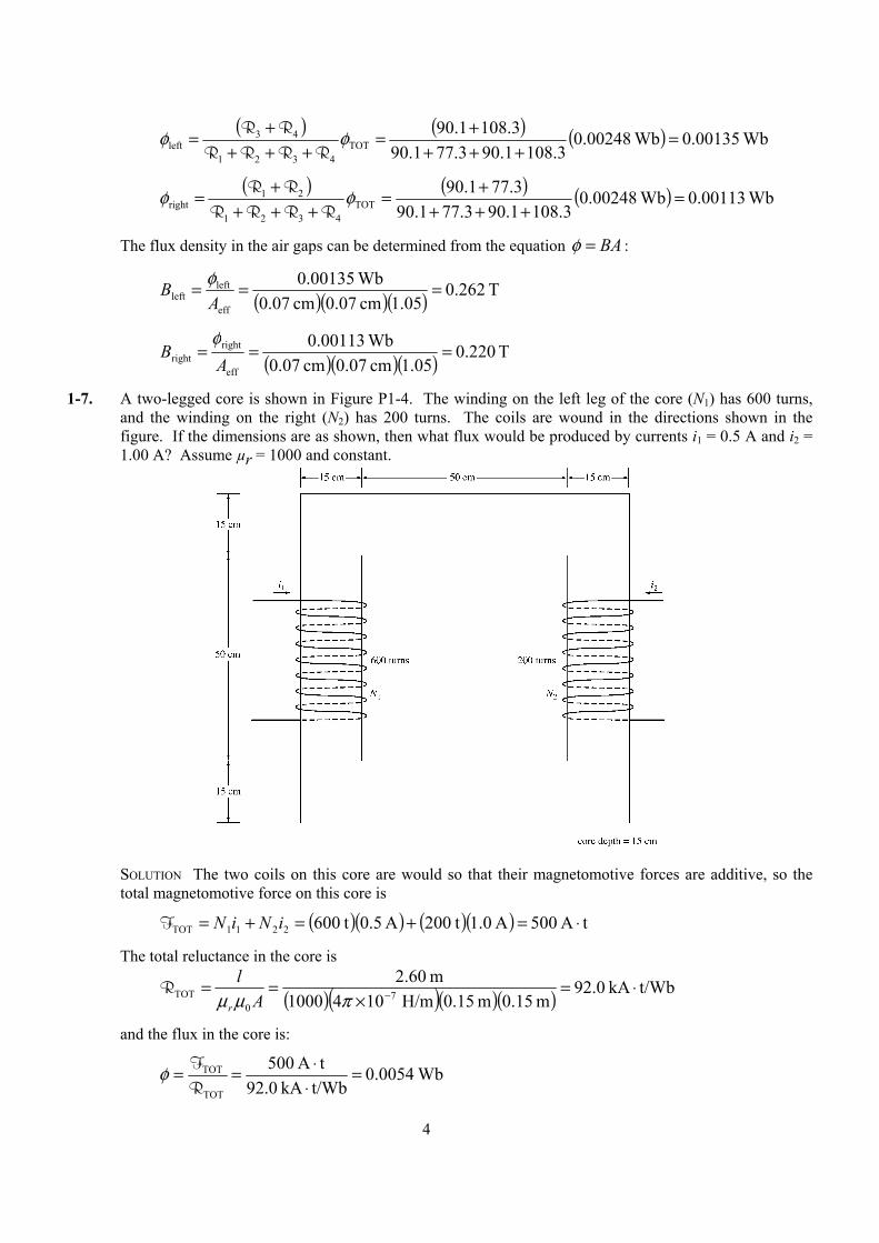
1-7. A two-legged core is shown in Figure P1-4. The winding on the left leg of the core (N1) has 600 turns, and the winding on the right (N2) has 200 turns. The coils are wound in the directions shown in the figure. If the dimensions are as shown, then what flux would be produced by currents i1 = 0.5 A and i2 = 1.00 A? Assume µr = 1000 and constant.
SOLUTION The two coils on this core are would so that their magnetomotive forces are additive, so the
total magnetomotive force on this core is
( )( ) ( )( ) tA 500A 0.1 t200A 5.0 t6002211TOT ⋅=+=+= iNiNF
The total reluctance in the core is
( )( )( )( ) t/WbkA 0.92m 0.15m 0.15 H/m1041000
m 60.27
0TOT ⋅=
×== −πµµ A
l
r
R
and the flux in the core is:
Wb 0054.0t/WbkA 92.0tA 500
TOT
TOT =⋅⋅==
RFφ
5
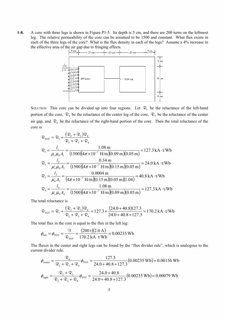
1-8. A core with three legs is shown in Figure P1-5. Its depth is 5 cm, and there are 200 turns on the leftmost leg. The relative permeability of the core can be assumed to be 1500 and constant. What flux exists in each of the three legs of the core? What is the flux density in each of the legs? Assume a 4% increase in the effective area of the air gap due to fringing effects.
SOLUTION This core can be divided up into four regions. Let 1R be the reluctance of the left-hand
portion of the core, 2R be the reluctance of the center leg of the core, 3R be the reluctance of the center air gap, and 4R be the reluctance of the right-hand portion of the core. Then the total reluctance of the core is
( )
432
4321TOT RRR
RRRRR
++++=
( )( )( )( ) t/WbkA 3.127m 0.05m 0.09 H/m1041500
m 08.17
10
11 ⋅=
×== −πµµ A
l
r
R
( )( )( )( ) t/WbkA 0.24m 0.05m 0.15 H/m1041500
m .3407
20
22 ⋅=
×== −πµµ A
l
r
R
( )( )( )( ) t/WbkA 40.8 04.1m 0.05m 0.15 H/m104
m 0004.07
30
33 ⋅=
×== −πµ A
lR
( )( )( )( ) t/WbkA 3.127m 0.05m 0.09 H/m1041500
m 08.17
40
44 ⋅=
×== −πµµ A
l
r
R
The total reluctance is
( ) ( ) t/WbkA 2.170
3.1278.400.243.1278.400.243.127
432
4321TOT ⋅=
++++=
++++=
RRRRRR
RR
The total flux in the core is equal to the flux in the left leg:
( )( ) Wb 00235.0
t/WbkA 170.2A 0.2 t200
TOTTOTleft =
⋅===
RFφφ
The fluxes in the center and right legs can be found by the “flux divider rule”, which is analogous to the current divider rule.
( ) Wb 00156.0Wb 00235.03.1278.400.24
3.127TOT
432
4center =
++=
++= φφ
RRRR
( ) Wb 00079.0Wb 00235.03.1278.400.24
8.400.24TOT
432
32right =
+++=
+++= φφ
RRRRR
6
The flux density in the legs can be determined from the equation BA=φ :
( )( ) T 522.0cm 0.05cm 0.09
Wb 00235.0leftleft ===
AB φ
( )( ) T 208.0cm 0.05cm 0.15
Wb 00156.0centercenter ===
AB φ
( )( ) T 176.0cm 0.05cm 0.09
Wb 00079.0leftright ===
AB φ
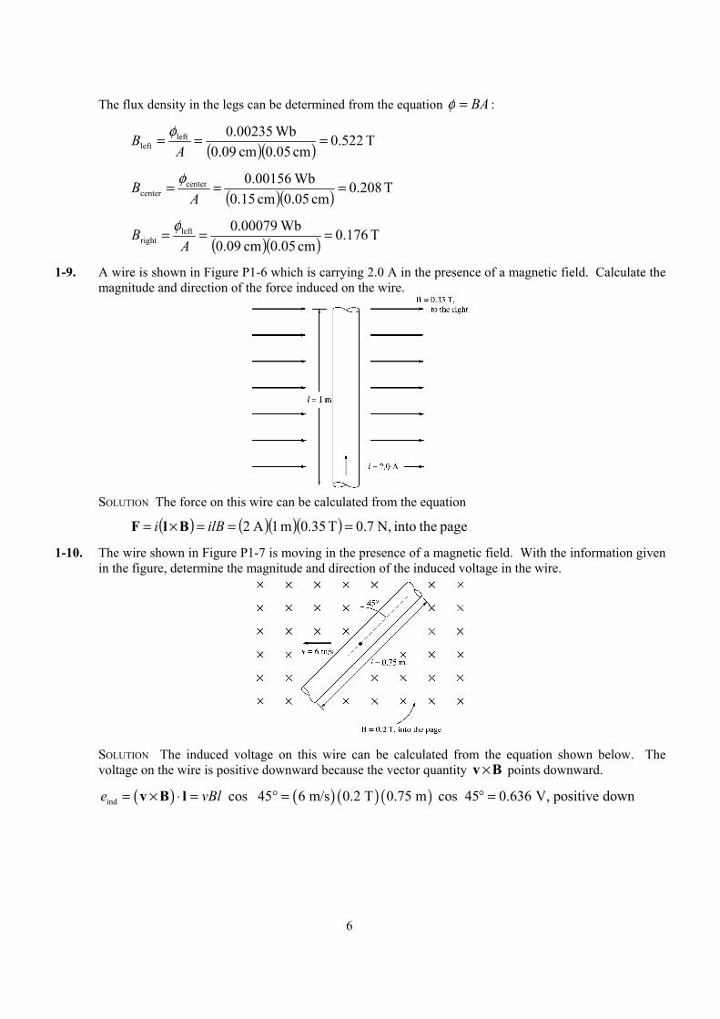
1-9. A wire is shown in Figure P1-6 which is carrying 2.0 A in the presence of a magnetic field. Calculate the magnitude and direction of the force induced on the wire.
SOLUTION The force on this wire can be calculated from the equation
( ) ( )( )( ) page theinto N, 7.0T 35.0m 1A 2 ===×= ilBi BlF
1-10. The wire shown in Figure P1-7 is moving in the presence of a magnetic field. With the information given in the figure, determine the magnitude and direction of the induced voltage in the wire.
SOLUTION The induced voltage on this wire can be calculated from the equation shown below. The
voltage on the wire is positive downward because the vector quantity Bv × points downward.
( ) ( ) ( ) ( )ind cos 45 6 m/s 0.2 T 0.75 m cos 45 0.636 V, positive downe vBl= × ⋅ = ° = ° =v B l
7
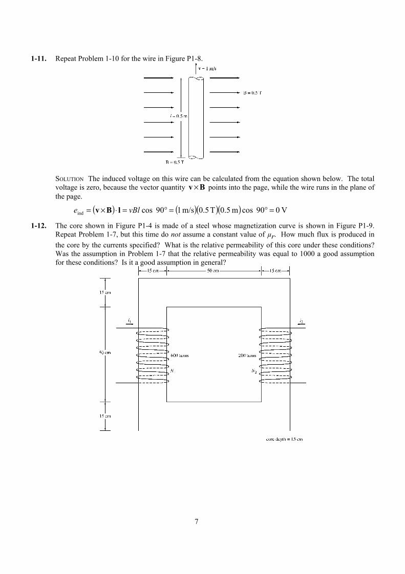
1-11. Repeat Problem 1-10 for the wire in Figure P1-8.
SOLUTION The induced voltage on this wire can be calculated from the equation shown below. The total
voltage is zero, because the vector quantity Bv × points into the page, while the wire runs in the plane of the page.
( ) ( )( )( ) V 090 cos m 0.5T 0.5m/s 109 cos ind =°=°=⋅×= vBle lBv
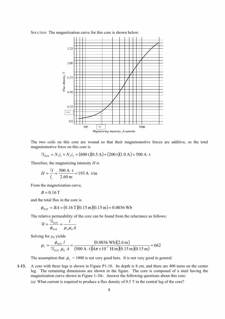
1-12. The core shown in Figure P1-4 is made of a steel whose magnetization curve is shown in Figure P1-9. Repeat Problem 1-7, but this time do not assume a constant value of µr. How much flux is produced in the core by the currents specified? What is the relative permeability of this core under these conditions? Was the assumption in Problem 1-7 that the relative permeability was equal to 1000 a good assumption for these conditions? Is it a good assumption in general?
8
SOLUTION The magnetization curve for this core is shown below:
193
0.16
The two coils on this core are wound so that their magnetomotive forces are additive, so the total
magnetomotive force on this core is
( )( ) ( )( ) tA 500A 0.1 t200A 5.0 t6002211TOT ⋅=+=+= iNiNF
Therefore, the magnetizing intensity H is
t/mA 193m 2.60
tA 500 ⋅=⋅==cl
H F
From the magnetization curve,
T 16.0=B
and the total flux in the core is
( )( )( ) Wb 0036.0m 0.15m 0.15T 16.0TOT === BAφ
The relative permeability of the core can be found from the reluctance as follows:
A
l
r 0TOT
TOT
µµφ== FR
Solving for µr yields
( )( )
( )( )( )( ) 662m 0.15m 0.15 H/m104tA 500
m 2.6Wb 0036.0
7-
0TOT
TOT =×⋅
==πµ
φµA
lr F
The assumption that rµ = 1000 is not very good here. It is not very good in general.
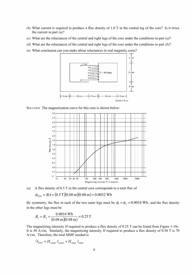
1-13. A core with three legs is shown in Figure P1-10. Its depth is 8 cm, and there are 400 turns on the center leg. The remaining dimensions are shown in the figure. The core is composed of a steel having the magnetization curve shown in Figure 1-10c. Answer the following questions about this core: (a) What current is required to produce a flux density of 0.5 T in the central leg of the core?
9
(b) What current is required to produce a flux density of 1.0 T in the central leg of the core? Is it twice the current in part (a)?
(c) What are the reluctances of the central and right legs of the core under the conditions in part (a)?
(d) What are the reluctances of the central and right legs of the core under the conditions in part (b)?
(e) What conclusion can you make about reluctances in real magnetic cores?
SOLUTION The magnetization curve for this core is shown below:
(a) A flux density of 0.5 T in the central core corresponds to a total flux of
( )( )( ) Wb 0032.0m 08.0m 08.0T 5.0TOT === BAφ
By symmetry, the flux in each of the two outer legs must be Wb 0016.021 == φφ , and the flux density in the other legs must be
( )( ) T 25.0m 08.0m 08.0
Wb 0016.021 === BB
The magnetizing intensity H required to produce a flux density of 0.25 T can be found from Figure 1-10c. It is 50 A·t/m. Similarly, the magnetizing intensity H required to produce a flux density of 0.50 T is 70 A·t/m. Therefore, the total MMF needed is
outeroutercentercenterTOT lHlH +=F
10
( )( ) ( )( ) tA 8.52m 72.0t/mA 50m 24.0t/mA 70TOT ⋅=⋅+⋅=F
and the required current is
A 13.0 t400
tA 8.52TOT =⋅==N
i F
(b) A flux density of 1.0 T in the central core corresponds to a total flux of
( )( )( ) Wb 0064.0m 08.0m 08.0T .01TOT === BAφ
By symmetry, the flux in each of the two outer legs must be Wb 0032.021 == φφ , and the flux density in the other legs must be
( )( ) T 50.0m 08.0m 08.0
Wb 0032.021 === BB
The magnetizing intensity H required to produce a flux density of 0.50 T can be found from Figure 1-10c. It is 70 A·t/m. Similarly, the magnetizing intensity H required to produce a flux density of 1.00 T is about 160 A·t/m. Therefore, the total MMF needed is
outeroutercentercenterTOT IHIH +=F ( )( ) ( )( ) tA 8.88m 72.0t/mA 70m 24.0t/mA 160TOT ⋅=⋅+⋅=F
and the required current is
A 22.0 t400
tA 8.88TOT =⋅==N
i φ
(c) The reluctance of the central leg of the core under the conditions of part (a) is:
( )( ) t/WbkA 25.5
Wb 0032.0m 0.24t/mA 70
TOT
TOTcent ⋅=⋅==
φFR
The reluctance of the right leg of the core under the conditions of part (a) is:
( )( ) t/WbkA 5.22
Wb 0016.0m 0.72t/mA 50
TOT
TOTright ⋅=⋅==
φFR
(d) The reluctance of the central leg of the core under the conditions of part (b) is:
( )( ) t/WbkA 0.6
Wb 0064.0m 0.24t/mA 160
TOT
TOTcent ⋅=⋅==
φFR
The reluctance of the right leg of the core under the conditions of part (b) is:
( )( ) t/WbkA 75.15
Wb 0032.0m 0.72t/mA 70
TOT
TOTright ⋅=⋅==
φFR
(e) The reluctances in real magnetic cores are not constant.
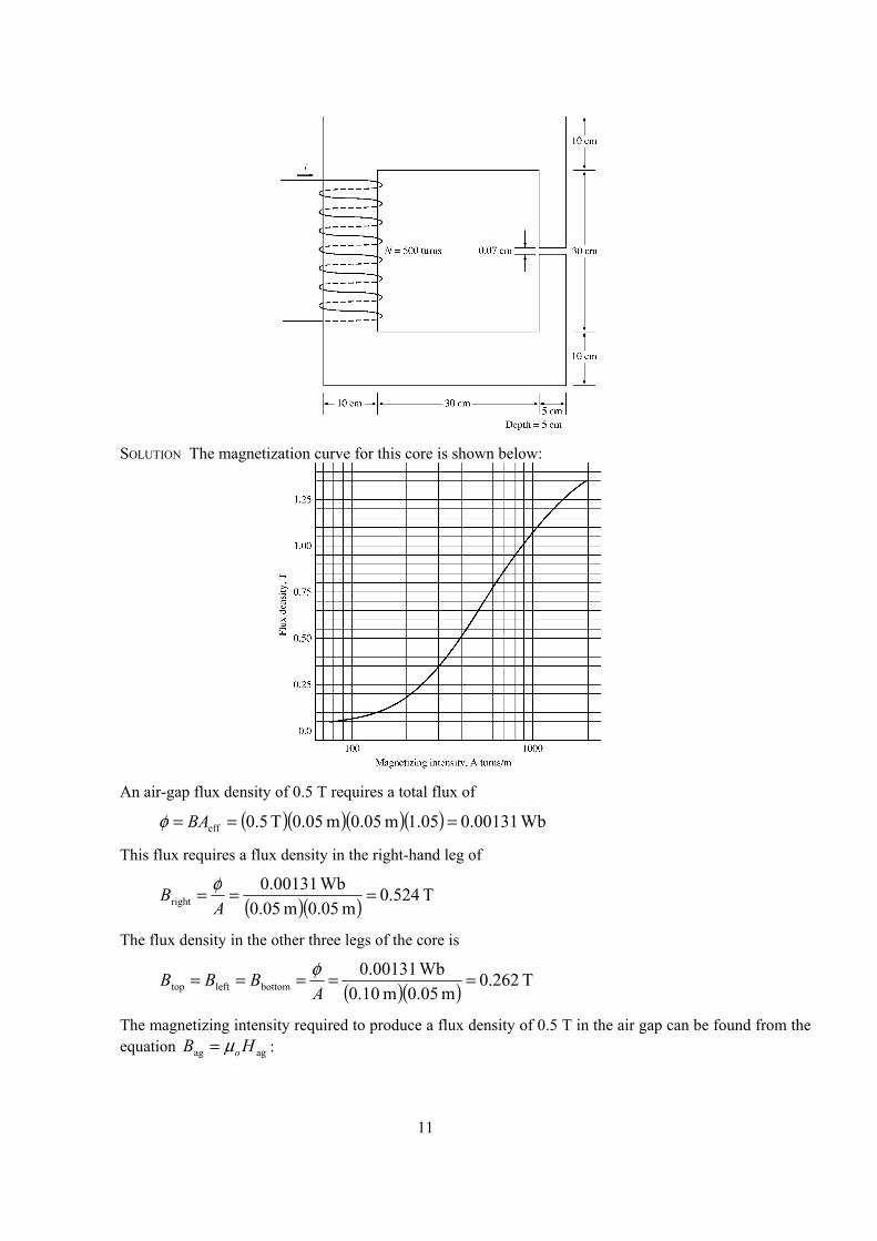
1-14. A two-legged magnetic core with an air gap is shown in Figure P1-11. The depth of the core is 5 cm, the length of the air gap in the core is 0.07 cm, and the number of turns on the coil is 500. The magnetization curve of the core material is shown in Figure P1-9. Assume a 5 percent increase in effective air-gap area to account for fringing. How much current is required to produce an air-gap flux density of 0.5 T? What are the flux densities of the four sides of the core at that current? What is the total flux present in the air gap?
11
SOLUTION The magnetization curve for this core is shown below:
An air-gap flux density of 0.5 T requires a total flux of
( )( )( )( ) Wb 00131.005.1m 05.0m 05.0T 5.0eff === BAφ
This flux requires a flux density in the right-hand leg of
( )( ) T 524.0m 05.0m 05.0
Wb 00131.0right ===
AB φ
The flux density in the other three legs of the core is
( )( ) T 262.0m 05.0m 10.0
Wb 00131.0bottomlefttop =====
ABBB φ
The magnetizing intensity required to produce a flux density of 0.5 T in the air gap can be found from the equation agag HB oµ= :
12
t/mkA 398 H/m104
T 0.57
0
agag ⋅=
×== −πµ
BH
The magnetizing intensity required to produce a flux density of 0.524 T in the right-hand leg of the core can be found from Figure P1-9 to be
t/mA 410right ⋅=H
The magnetizing intensity required to produce a flux density of 0.262 T in the right-hand leg of the core can be found from Figure P1-9 to be
t/mA 240bottomlefttop ⋅=== HHH
The total MMF required to produce the flux is
bottombottomleftlefttoptoprightrightagagTOT lHlHlHlHlH ++++=F
( )( ) ( )( ) ( )( )m 40.0t/mA 2403m 40.0t/mA 410m 0007.0t/mkA 983TOT ⋅+⋅+⋅=F tA 7312881646.278TOT ⋅=++=F
and the required current is
A 46.1 t500
tA 317TOT =⋅==N
i F
The flux densities in the four sides of the core and the total flux present in the air gap were calculated above.
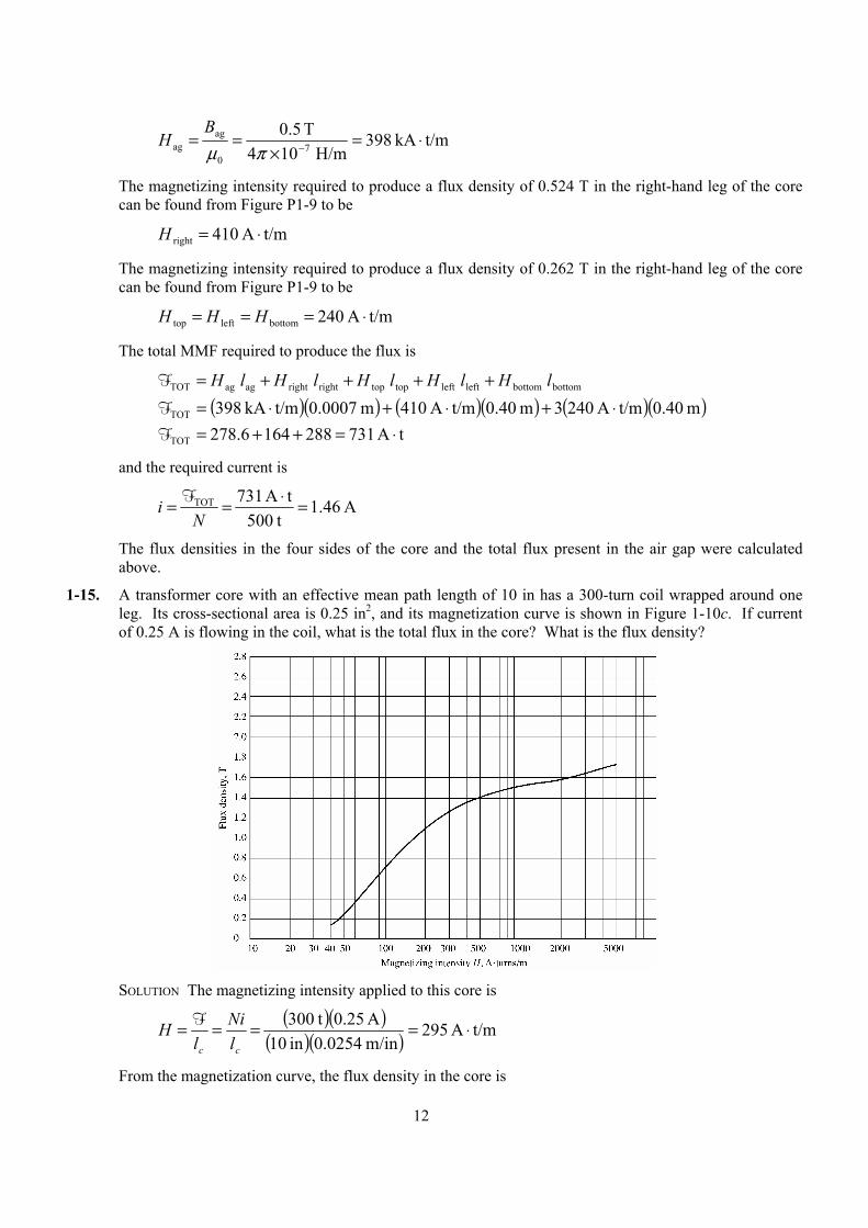
1-15. A transformer core with an effective mean path length of 10 in has a 300-turn coil wrapped around one leg. Its cross-sectional area is 0.25 in2, and its magnetization curve is shown in Figure 1-10c. If current of 0.25 A is flowing in the coil, what is the total flux in the core? What is the flux density?
SOLUTION The magnetizing intensity applied to this core is
( )( )
( )( ) t/mA 295m/in 0254.0in 10A 25.0 t300 ⋅====
cc lNi
lH F
From the magnetization curve, the flux density in the core is
13
T 27.1=B
The total flux in the core is
( )( ) Wb 000205.0in 1
m 0254.0in 25.0T 27.12
2 =
== BAφ
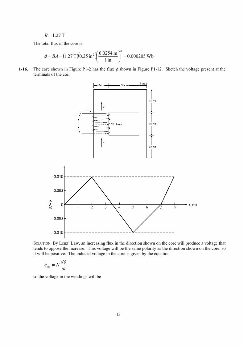
1-16. The core shown in Figure P1-2 has the flux φ shown in Figure P1-12. Sketch the voltage present at the terminals of the coil.
SOLUTION By Lenz’ Law, an increasing flux in the direction shown on the core will produce a voltage that
tends to oppose the increase. This voltage will be the same polarity as the direction shown on the core, so it will be positive. The induced voltage in the core is given by the equation
dtdNe φ=ind
so the voltage in the windings will be
14
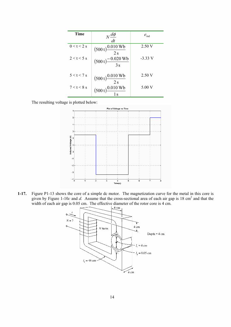
Time dtdN φ
inde
0 < t < 2 s ( )s 2Wb 010.0 t500
2.50 V
2 < t < 5 s ( )s 3
Wb 020.0 t500 −
-3.33 V
5 < t < 7 s ( )s 2Wb 010.0 t500
2.50 V
7 < t < 8 s ( )s 1Wb 010.0 t500
5.00 V
The resulting voltage is plotted below:
1-17. Figure P1-13 shows the core of a simple dc motor. The magnetization curve for the metal in this core is
given by Figure 1-10c and d. Assume that the cross-sectional area of each air gap is 18 cm2 and that the width of each air gap is 0.05 cm. The effective diameter of the rotor core is 4 cm.
15
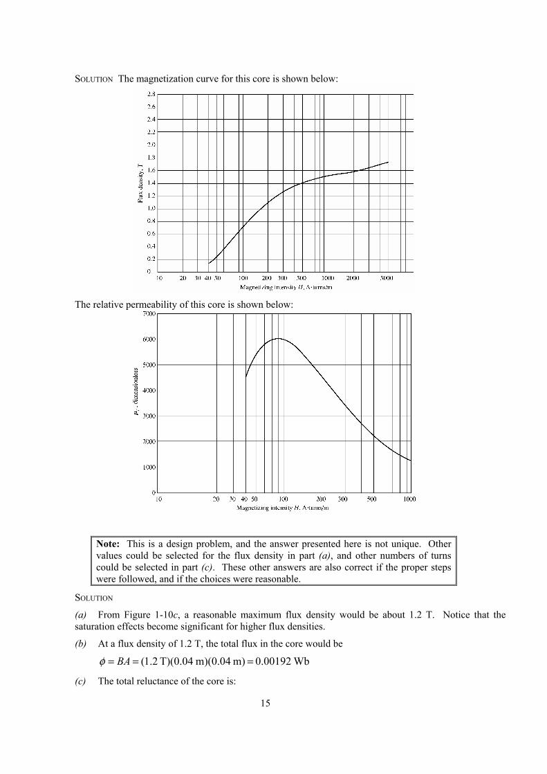
SOLUTION The magnetization curve for this core is shown below:
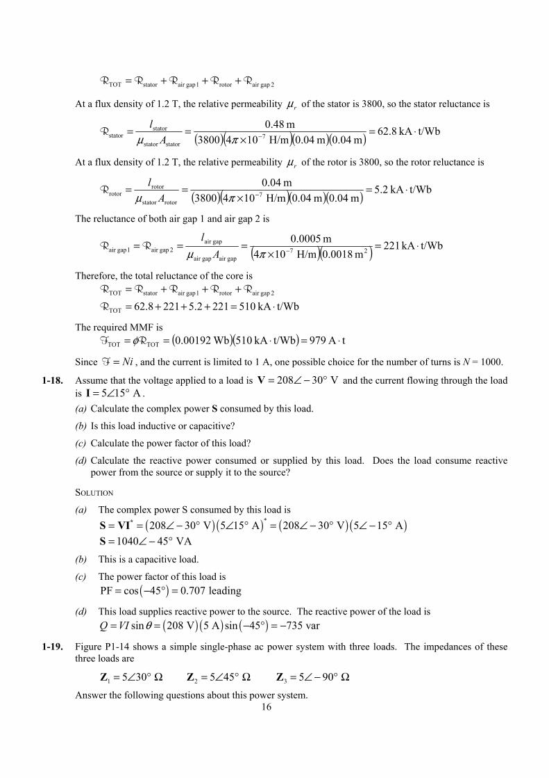
The relative permeability of this core is shown below:
Note: This is a design problem, and the answer presented here is not unique. Other values could be selected for the flux density in part (a), and other numbers of turns could be selected in part (c). These other answers are also correct if the proper steps were followed, and if the choices were reasonable.
SOLUTION
(a) From Figure 1-10c, a reasonable maximum flux density would be about 1.2 T. Notice that the saturation effects become significant for higher flux densities.
(b) At a flux density of 1.2 T, the total flux in the core would be
Wb 0.00192 m) m)(0.04 T)(0.04 2.1( === BAφ
(c) The total reluctance of the core is:
16
2 gapair rotor1 gapair statorTOT RRRRR +++=
At a flux density of 1.2 T, the relative permeability rµ of the stator is 3800, so the stator reluctance is
( )( )( )( ) t/WbkA 8.62m 04.0m 04.0 H/m1043800
m 48.07
statorstator
statorstator ⋅=
×== −πµ A
lR
At a flux density of 1.2 T, the relative permeability rµ of the rotor is 3800, so the rotor reluctance is
( )( )( )( ) t/WbkA 2.5m 04.0m 04.0 H/m1043800
m 04.07
rotorstator
rotorrotor ⋅=
×== −πµ A
lR
The reluctance of both air gap 1 and air gap 2 is
( )( ) t/WbkA 221m 0018.0 H/m104
m 0005.027
gapair gapair
gapair 2 gapair 1 gapair ⋅=
×=== −πµ A
lRR
Therefore, the total reluctance of the core is 2 gapair rotor1 gapair statorTOT RRRRR +++=
t/WbkA 5102212.52218.62TOT ⋅=+++=R
The required MMF is ( )( ) tA 979t/WbkA 510Wb 00192.0TOTTOT ⋅=⋅== RF φ
Since Ni=F , and the current is limited to 1 A, one possible choice for the number of turns is N = 1000.
1-18. Assume that the voltage applied to a load is 208 30 V= ∠ − °V and the current flowing through the load is 5 15 A= ∠ °I . (a) Calculate the complex power S consumed by this load.
(b) Is this load inductive or capacitive?
(c) Calculate the power factor of this load?
(d) Calculate the reactive power consumed or supplied by this load. Does the load consume reactive power from the source or supply it to the source?
SOLUTION
(a) The complex power S consumed by this load is ( ) ( ) ( ) ( )*208 30 V 5 15 A 208 30 V 5 15 A= = ∠ − ° ∠ ° = ∠ − ° ∠ − °*S VI 1040 45 VA= ∠ − °S
(b) This is a capacitive load.
(c) The power factor of this load is ( )PF cos 45 0.707 leading= − ° =
(d) This load supplies reactive power to the source. The reactive power of the load is ( ) ( ) ( )sin 208 V 5 A sin 45 735 varQ VI θ= = − ° = −
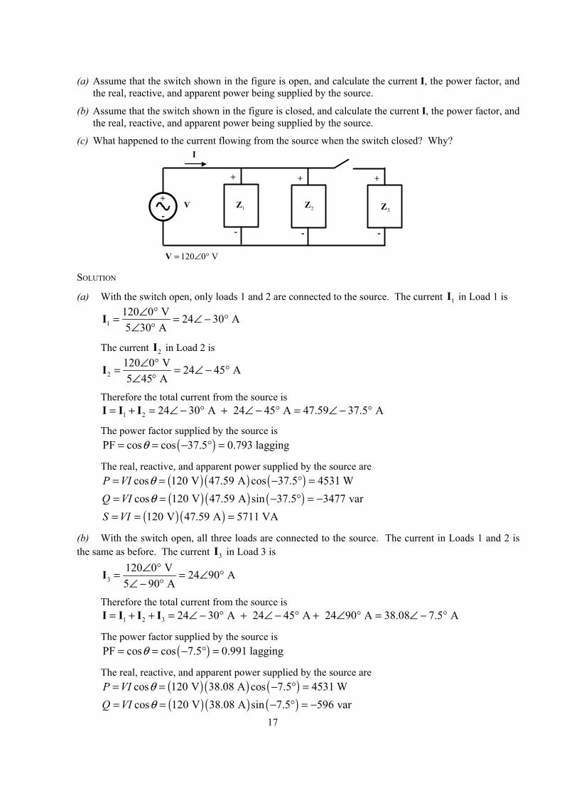
1-19. Figure P1-14 shows a simple single-phase ac power system with three loads. The impedances of these three loads are
1 5 30 = ∠ ° ΩZ 2 5 45 = ∠ ° ΩZ 3 5 90 = ∠ − ° ΩZ
Answer the following questions about this power system.
17
(a) Assume that the switch shown in the figure is open, and calculate the current I, the power factor, and the real, reactive, and apparent power being supplied by the source.
(b) Assume that the switch shown in the figure is closed, and calculate the current I, the power factor, and the real, reactive, and apparent power being supplied by the source.
(c) What happened to the current flowing from the source when the switch closed? Why?
+
-
I
V
+
-
+
-
+
-
1Z 2Z3Z
120 0 V= ∠ °V SOLUTION
(a) With the switch open, only loads 1 and 2 are connected to the source. The current 1I in Load 1 is
1120 0 V 24 30 A5 30 A
∠ °= = ∠ − °∠ °
I
The current 2I in Load 2 is
2120 0 V 24 45 A5 45 A
∠ °= = ∠ − °∠ °
I
Therefore the total current from the source is 1 2 24 30 A 24 45 A 47.59 37.5 A= + = ∠ − ° + ∠ − ° = ∠ − °I I I
The power factor supplied by the source is ( )PF cos cos 37.5 0.793 laggingθ= = − ° =
The real, reactive, and apparent power supplied by the source are ( ) ( ) ( )cos 120 V 47.59 A cos 37.5 4531 WP VI θ= = − ° =
( ) ( ) ( )cos 120 V 47.59 A sin 37.5 3477 varQ VI θ= = − ° = −
( ) ( )120 V 47.59 A 5711 VAS VI= = =
(b) With the switch open, all three loads are connected to the source. The current in Loads 1 and 2 is the same as before. The current 3I in Load 3 is
3120 0 V 24 90 A5 90 A
∠ °= = ∠ °∠ − °
I
Therefore the total current from the source is 1 2 3 24 30 A 24 45 A 24 90 A 38.08 7.5 A= + + = ∠ − ° + ∠ − ° + ∠ ° = ∠ − °I I I I
The power factor supplied by the source is ( )PF cos cos 7.5 0.991 laggingθ= = − ° =
The real, reactive, and apparent power supplied by the source are ( ) ( ) ( )cos 120 V 38.08 A cos 7.5 4531 WP VI θ= = − ° =
( ) ( ) ( )cos 120 V 38.08 A sin 7.5 596 varQ VI θ= = − ° = −
18
( ) ( )120 V 38.08 A 4570 VAS VI= = =
(c) The current flowing decreased when the switch closed, because most of the reactive power being consumed by Loads 1 and 2 is being supplied by Load 3. Since less reactive power has to be supplied by the source, the total current flow decireases.
1-20. Demonstrate that Equation (1-50) can be derived from Equation (1-49) using simple trigonometric identities:
( )( ) ( ) ( ) 2 cos cosp t v t i t VI t tω ω θ= = − (1-49)
( )( ) cos 1 cos2 sin sin 2p t VI t VI tθ ω θ ω= + + (1-50)
SOLUTION
The first step is to apply the following identity from Appendix D:
( ) ( )1cos cos cos cos2
α β α β α β= − + +
The result is
( )( ) ( ) ( ) 2 cos cosp t v t i t VI t tω ω θ= = − (1-49)
( ) ( )1( ) 2 cos cos2
p t VI t t t tω ω θ ω ω θ = − + + + −
( )( ) cos cos 2p t VI tθ ω θ = + −
Now we must apply the angle addition identity from Appendix D to the second term:
( )cos cos cos sin sinα β α β α β− = +
The result is
[ ]( ) cos cos2 cos sin 2 sinp t VI t tθ ω θ ω θ= + +
Collecting terms yields the final result:
( )( ) cos 1 cos2 sin sin 2p t VI t VI tθ ω θ ω= + +
19
Chapter 2: Three-Phase Circuits
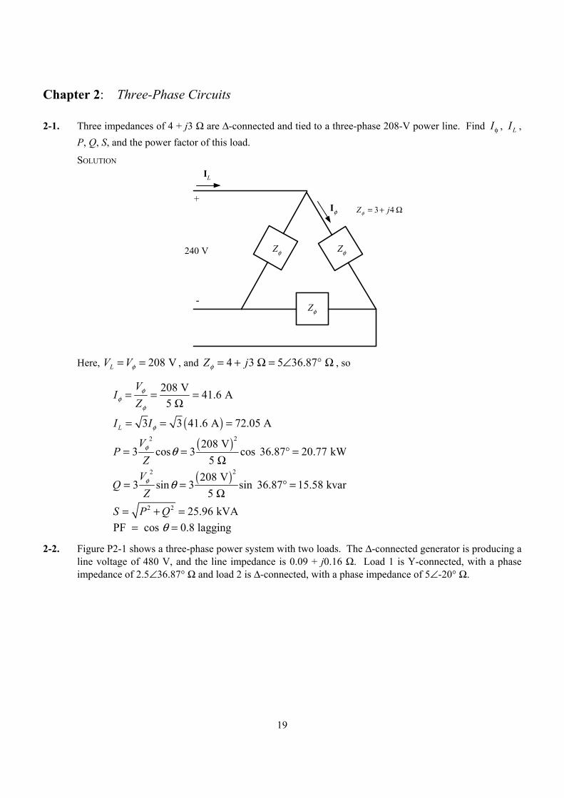
2-1. Three impedances of 4 + j3 Ω are ∆-connected and tied to a three-phase 208-V power line. Find Iφ , IL , P, Q, S, and the power factor of this load.
SOLUTION
Zφ
Zφ
Zφ
+
-
240 V
IL
Iφ Ω+= 43 jZφ
Here, 208 VLV Vφ= = , and 4 3 5 36.87 Z jφ = + Ω = ∠ ° Ω , so
208 V 41.6 A5
VI
Zφ
φφ
= = =Ω
( )3 3 41.6 A 72.05 ALI Iφ= = =
( )22 208 V
3 cos 3 cos 36.87 20.77 kW5
VP
Zφ θ= = ° =
Ω
( )22 208 V
3 sin 3 sin 36.87 15.58 kvar5
VQ
Zφ θ= = ° =
Ω
2 2 25.96 kVAS P Q= + = PF cos 0.8 laggingθ= =
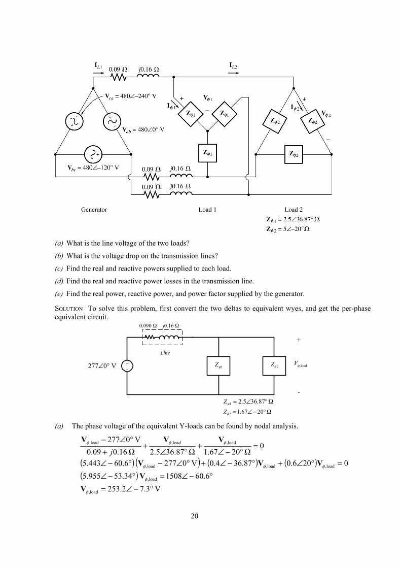
2-2. Figure P2-1 shows a three-phase power system with two loads. The ∆-connected generator is producing a line voltage of 480 V, and the line impedance is 0.09 + j0.16 Ω. Load 1 is Y-connected, with a phase impedance of 2.5∠36.87° Ω and load 2 is ∆-connected, with a phase impedance of 5∠-20° Ω.
20
(a) What is the line voltage of the two loads?
(b) What is the voltage drop on the transmission lines?
(c) Find the real and reactive powers supplied to each load.
(d) Find the real and reactive power losses in the transmission line.
(e) Find the real power, reactive power, and power factor supplied by the generator.
SOLUTION To solve this problem, first convert the two deltas to equivalent wyes, and get the per-phase equivalent circuit.
+-277∠0° V
Line
0.090 Ω j0.16 Ω
1φZ 2φZ
Ω°∠= 87.365.21φZΩ°−∠= 2067.12φZ
load,φV
+
-
(a) The phase voltage of the equivalent Y-loads can be found by nodal analysis.
0 2067.1 36.872.5 16.009.0
V 0277 load,load,load, =Ω°−∠
+Ω°∠
+Ω+°∠− φφφ VVV
j
( ) ( ) ( ) ( ) 0206.087.364.0V 0277 6.60443.5 load,load,load, =°∠+°−∠+°∠−°−∠ φφφ VVV
( ) °−∠=°−∠ 6.601508 34.53955.5 load,φV
V 3.72.253load, °−∠=φV
21
Therefore, the line voltage at the loads is 3 439 VLV Vφ = .
(b) The voltage drop in the transmission lines is
V 5241.3 7.3-253.2 - V 0277load,gen,line °∠=°∠°∠=−=∆ φφ VVV
(c) The real and reactive power of each load is
( ) kW 61.636.87 cos
2.5V 2.2533cos3
22
1 =°Ω
== θφ
ZV
P
( )22
1253.2 V
3 sin 3 sin 36.87 46.2 kvar2.5
VQ
Zφ θ= = ° =
Ω
( ) ( ) kW 108.420- cos
1.67V 2.2533cos3
22
2 =°Ω
== θφ
ZV
P
( ) ( )
22
2253.2 V
3 sin 3 sin -20 39.5 kvar1.67
VQ
Zφ θ= = ° = −
Ω
(d) The line current is
A6.8225 0.160.09
V 5241.3
line
lineline °−∠=
Ω+°∠=∆=
jZVI
Therefore, the loses in the transmission line are
( ) ( ) kW 7.13 09.0A 225 33 2line
2lineline =Ω== RIP
( ) ( )22line line line3 3 225 A 0.16 24.3 kvarQ I X= = Ω =
(e) The real and reactive power supplied by the generator is
kW 183.7kW 108.4 kW 6.61kW 13.721linegen =++=++= PPPP
gen line 1 2 24.3 kvar 46.2 kvar 39.5 kvar 31 kvarQ Q Q Q= + + = + − =
The power factor of the generator is
gen-1 1
gen
31 kvarPF cos tan cos tan 0.986 lagging183.7 kW
QP
− = = =
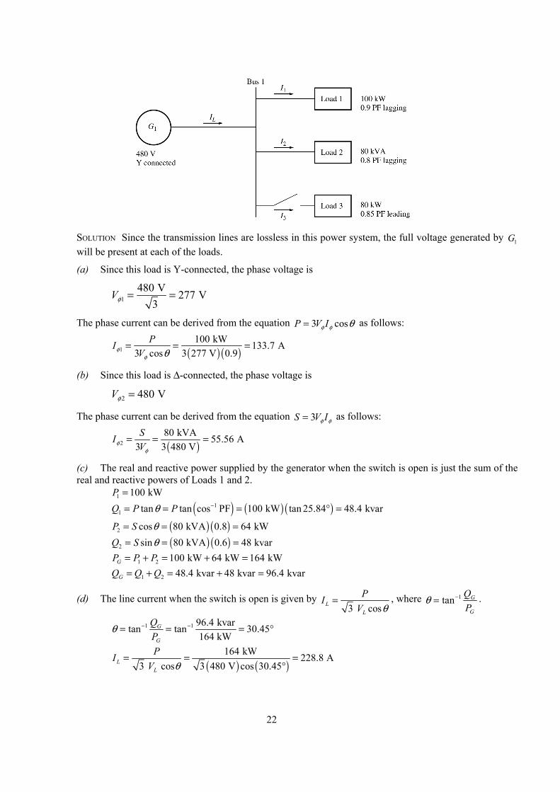
2-3. The figure shown below shows a one-line diagram of a simple power system containing a single 480 V generator and three loads. Assume that the transmission lines in this power system are lossless, and answer the following questions. (a) Assume that Load 1 is Y-connected. What are the phase voltage and currents in that load?
(b) Assume that Load 2 is ∆-connected. What are the phase voltage and currents in that load?
(c) What real, reactive, and apparent power does the generator supply when the switch is open?
(d) What is the total line current LI when the switch is open?
(e) What real, reactive, and apparent power does the generator supply when the switch is closed?
(f) What is the total line current LI when the switch is closed?
(g) How does the total line current LI compare to the sum of the three individual currents 1 2 3I I I+ + ? If they are not equal, why not?
22
SOLUTION Since the transmission lines are lossless in this power system, the full voltage generated by 1G
will be present at each of the loads.
(a) Since this load is Y-connected, the phase voltage is
1480 V 277 V
3Vφ = =
The phase current can be derived from the equation 3 cosP V Iφ φ θ= as follows:
( ) ( )1
100 kW 133.7 A3 cos 3 277 V 0.9
PIVφ
φ θ= = =
(b) Since this load is ∆-connected, the phase voltage is
2 480 VVφ =
The phase current can be derived from the equation 3S V Iφ φ= as follows:
( )2
80 kVA 55.56 A3 3 480 VSIVφ
φ
= = =
(c) The real and reactive power supplied by the generator when the switch is open is just the sum of the real and reactive powers of Loads 1 and 2.
1 100 kWP = ( ) ( ) ( )1
1 tan tan cos PF 100 kW tan 25.84 48.4 kvarQ P Pθ −= = = ° =
( ) ( )2 cos 80 kVA 0.8 64 kWP S θ= = = ( ) ( )2 sin 80 kVA 0.6 48 kvarQ S θ= = = 1 2 100 kW 64 kW 164 kWGP P P= + = + = 1 2 48.4 kvar 48 kvar 96.4 kvarGQ Q Q= + = + =
(d) The line current when the switch is open is given by 3 cosL
L
PIV θ
= , where 1tan G
G
QP
θ −= .
1 1 96.4 kvartan tan 30.45164 kW
G
G
QP
θ − −= = = °
( ) ( )
164 kW 228.8 A3 cos 3 480 V cos 30.45L
L
PIV θ
= = =°
23
(e) The real and reactive power supplied by the generator when the switch is closed is just the sum of the real and reactive powers of Loads 1, 2, and 3. The powers of Loads 1 and 2 have already been calculated. The real and reactive power of Load 3 are:
3 80 kWP = ( ) ( ) ( )1
3 tan tan cos PF 80 kW tan 31.79 49.6 kvarQ P Pθ −= = = − ° = −
1 2 3 100 kW 64 kW 80 kW 244 kWGP P P P= + + = + + = 1 2 3 48.4 kvar 48 kvar 49.6 kvar 46.8 kvarGQ Q Q Q= + + = + − =
(f) The line current when the switch is closed is given by 3 cosL
L
PIV θ
= , where 1tan G
G
QP
θ −= .
1 1 46.8 kvartan tan 10.86244 kW
G
G
QP
θ − −= = = °
( ) ( )
244 kW 298.8 A3 cos 3 480 V cos 10.86L
L
PIV θ
= = =°
(g) The total line current from the generator is 298.8 A. The line currents to each individual load are:
( ) ( )1
11
100 kW 133.6 A3 cos 3 480 V 0.9L
L
PIV θ
= = =
( )
22
80 kVA 96.2 A3 3 480 VL
L
SIV
= = =
( ) ( )
33
3
80 kW 113.2 A3 cos 3 480 V 0.85L
L
PIV θ
= = =
The sum of the three individual line currents is 343 A, while the current supplied by the generator is 298.8 A. These values are not the same, because the three loads have different impedance angles. Essentially, Load 3 is supplying some of the reactive power being consumed by Loads 1 and 2, so that it does not have to come from the generator.
2-4. Prove that the line voltage of a Y-connected generator with an acb phase sequence lags the corresponding phase voltage by 30°. Draw a phasor diagram showing the phase and line voltages for this generator.
SOLUTION If the generator has an acb phase sequence, then the three phase voltages will be 0an Vφ= ∠ °V
240bn Vφ= ∠ − °V
120cn Vφ= ∠ − °V
The relationship between line voltage and phase voltage is derived below. By Kirchhoff’s voltage law, the line-to-line voltage abV is given by
ab a b= −V V V 0 240ab V Vφ φ= ∠ ° − ∠ − °V
1 3 3 3 2 2 2 2ab V V j V V j Vφ φ φ φ φ
= − − + = −
V
3 132 2ab V jφ
= −
V
3 30 ab Vφ= ∠ − °V
24
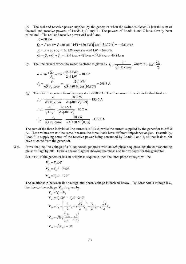
Thus the line voltage lags the corresponding phase voltage by 30°. The phasor diagram for this connection is shown below.
Van
Vbn
VcnVab
Vbc
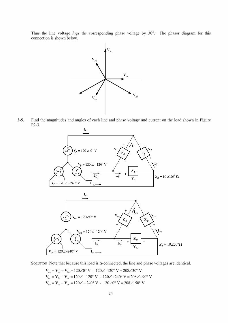
2-5. Find the magnitudes and angles of each line and phase voltage and current on the load shown in Figure
P2-3.
SOLUTION Note that because this load is ∆-connected, the line and phase voltages are identical.
120 0 V 120 120 V 208 30 Vab an bn - -= − = ∠ ° ∠ ° = ∠ °V V V 120 120 V 120 240 V 208 90 Vbc bn cn - - -= − = ∠ − ° ∠ ° = ∠ °V V V 120 240 V 120 0 V 208 150 Vca cn an -= − = ∠ − ° ∠ ° = ∠ °V V V
25
208 30 V 20.8 10 A10 20
abab Zφ
∠ °= = = ∠ °∠ ° Ω
VI
208 90 V 20.8 110 A10 20
bcbc Zφ
∠ − °= = = ∠ − °∠ ° Ω
VI
208 150 V 20.8 130 A10 20
caca Zφ
∠ °= = = ∠ °∠ ° Ω
VI
20.8 10 A 20.8 130 A 36 20 Aa ab ca - -= − = ∠ ° ∠ ° = ∠ °I I I 20.8 110 A 20.8 10 A 36 140 Ab bc ab - -= − = ∠ − ° ∠ ° = ∠ °I I I 20.8 130 A 20.8 -110 A 36 100 Ac ca bc -= − = ∠ ° ∠ ° = ∠ °I I I
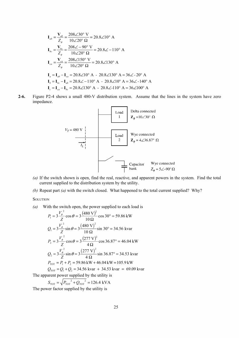
2-6. Figure P2-4 shows a small 480-V distribution system. Assume that the lines in the system have zero impedance.
(a) If the switch shown is open, find the real, reactive, and apparent powers in the system. Find the total
current supplied to the distribution system by the utility.
(b) Repeat part (a) with the switch closed. What happened to the total current supplied? Why?
SOLUTION
(a) With the switch open, the power supplied to each load is
( ) kW 86.9530 cos 10V 8043cos3
22
1 =°Ω
== θφ
ZV
P
( )22
1480 V
3 sin 3 sin 30 34.56 kvar10
VQ
Zφ θ= = ° =
Ω
( ) kW 04.4636.87 cos 4
V 2773cos322
2 =°Ω
== θφ
ZV
P
( )22
2277 V
3 sin 3 sin 36.87 34.53 kvar4
VQ
Zφ θ= = ° =
Ω
kW 105.9 kW 46.04 kW 86.5921TOT =+=+= PPP TOT 1 2 34.56 kvar 34.53 kvar 69.09 kvarQ Q Q= + = + = The apparent power supplied by the utility is 2 2
TOT TOT TOT 126.4 kVAS P Q= + = The power factor supplied by the utility is
26
-1 1TOT
TOT
69.09 kvarPF cos tan cos tan 0.838 lagging105.9 kW
QP
− = = =
The current supplied by the utility is
( ) ( )
TOT 105.9 kW 152 A3 PF 3 480 V 0.838L
T
PIV
= = =
(b) With the switch closed, 3P is added to the circuit. The real and reactive power of 3P is
( ) ( ) kW 090 cos 5
V 2773cos322
3 =°Ω
== -Z
VP θφ
( ) ( )22
3277 V
3 sin 3 sin 90 46.06 kvar5
VP -
Zφ θ= = ° = −
Ω
TOT 1 2 3 59.86 kW 46.04 kW 0 kW 105.9 kWP P P P= + + = + + = TOT 1 2 3 34.56 kvar 34.53 kvar 46.06 kvar 23.03 kvarQ Q Q Q= + + = + − = The apparent power supplied by the utility is 2 2
TOT TOT TOT 108.4 kVAS P Q= + = The power factor supplied by the utility is
-1 1TOT
TOT
23.03 kVARPF cos tan cos tan 0.977 lagging105.9 kW
QP
− = = =
The current supplied by the utility is
( ) ( )
TOT 105.9 kW 130.4 A3 PF 3 480 V 0.977L
T
PIV
= = =
27
Chapter 3: Transformers
3-1. The secondary winding of a transformer has a terminal voltage of v t ts ( ) .= 282 8 sin 377 V . The turns ratio of the transformer is 50:200 (a = 0.25). If the secondary current of the transformer is
( )i t ts ( ) . .= − °7 07 3687 sin 377 A , what is the primary current of this transformer? What are its voltage regulation and efficiency? The impedances of this transformer referred to the primary side are
Req = 0 05. Ω RC = 75 Ω
X eq = 0 225. Ω X M = 20 Ω
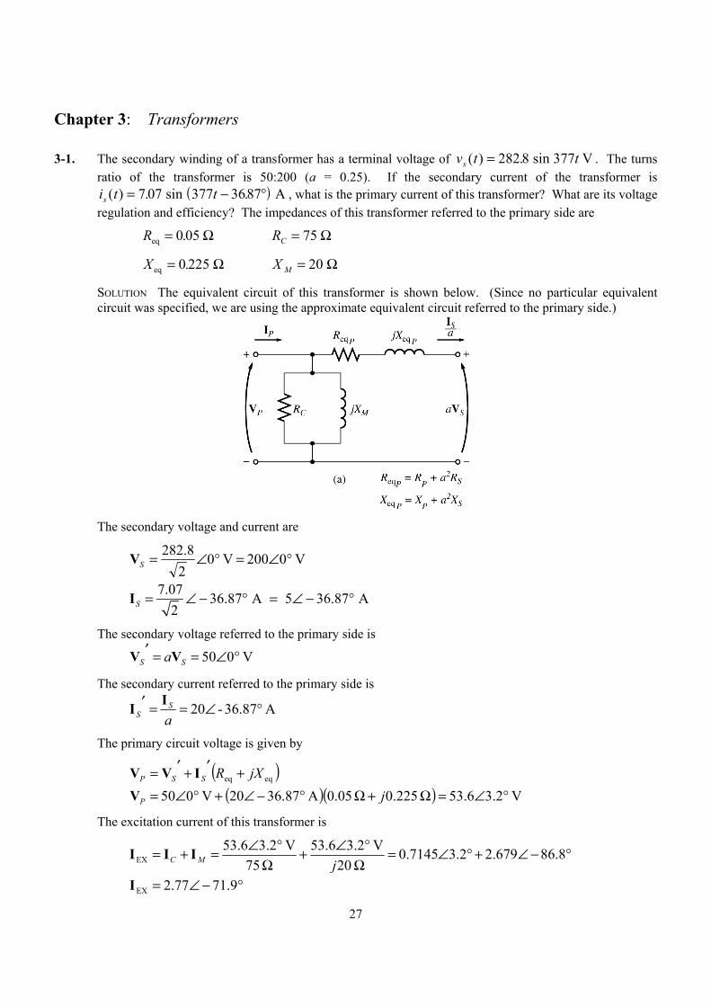
SOLUTION The equivalent circuit of this transformer is shown below. (Since no particular equivalent circuit was specified, we are using the approximate equivalent circuit referred to the primary side.)
The secondary voltage and current are
V 0200 V 02
8.282 °∠=°∠=SV
7.07 36.87 A 5 36.87 A
2S = ∠ − ° = ∠ − °I
The secondary voltage referred to the primary side is
V 050 °∠==′SS aVV
The secondary current referred to the primary side is
A 87.36-20 °∠==′aS
SII
The primary circuit voltage is given by
( )eqeq jXRSSP +′+′= IVV
( )( ) V 2.36.53 225.0 05.0A 87.3620V 050 °∠=Ω+Ω°−∠+°∠= jPV
The excitation current of this transformer is
°−∠+°∠=Ω
°∠+Ω
°∠=+= 8.86679.22.37145.0 20
V 2.36.53 75
V 2.36.53EX jMC III
°−∠= 9.7177.2EXI
28
Therefore, the total primary current of this transformer is
A 0.413.229.7177.287.3620EX °−∠=°−∠+°−∠=+′= III SP
The voltage regulation of the transformer at this load is
%2.7%10050
506.53%100VR =×−=×−=S
SP
aVaVV
The input power to this transformer is
( ) ( ) ( )IN cos 53.6 V 22.3 A cos 3.2 41.0P PP V I θ= = ° − − °
( )( ) W 85744.2 cosA 3.22V 6.53IN =°=P
The output power from this transformer is
( )( ) ( ) W 80087.36 cosA 5V 002 cos OUT =°== θSS IVP
Therefore, the transformer’s efficiency is
%4.93%100W 857W 800%100
IN
OUT =×=×=P
Pη
3-2. A 20-kVA 8000/277-V distribution transformer has the following resistances and reactances:
Ω= 32PR Ω= 05.0SR Ω= 45PX 0.06 SX = Ω Ω= k 250CR Ω= k 30MX
The excitation branch impedances are given referred to the high-voltage side of the transformer. (a) Find the equivalent circuit of this transformer referred to the high-voltage side.
(b) Find the per-unit equivalent circuit of this transformer.
(c) Assume that this transformer is supplying rated load at 277 V and 0.8 PF lagging. What is this transformer’s input voltage? What is its voltage regulation?
(d) What is the transformer’s efficiency under the conditions of part (c)?
SOLUTION
(a) The turns ratio of this transformer is a = 8000/277 = 28.89. Therefore, the secondary impedances referred to the primary side are
( ) ( ) Ω=Ω==′ 7.41 05.089.28 22SS RaR
( ) ( ) Ω=Ω==′ 1.50 06.089.28 22SS XaX
29
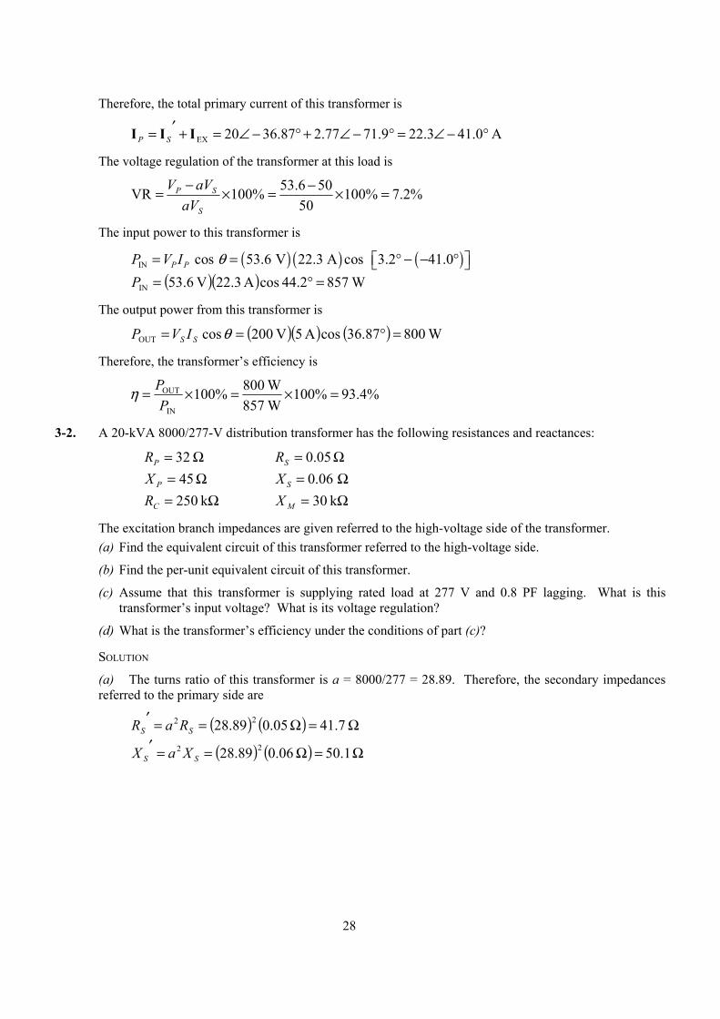
The resulting equivalent circuit is
32 Ω 41.7 Ω
250 kΩ
j45 Ω j50.1 Ω
j30 kΩ
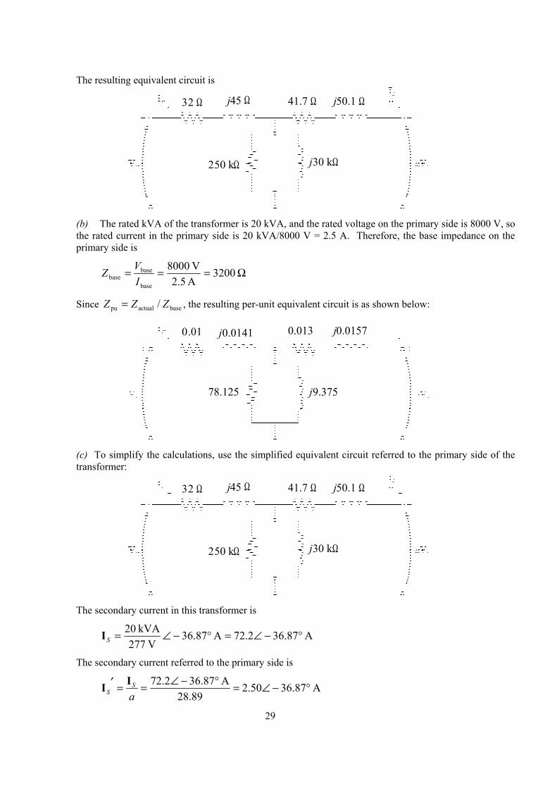
(b) The rated kVA of the transformer is 20 kVA, and the rated voltage on the primary side is 8000 V, so
the rated current in the primary side is 20 kVA/8000 V = 2.5 A. Therefore, the base impedance on the primary side is
Ω=== 3200A 2.5V 8000
base
basebase I
VZ
Since baseactualpu / ZZZ = , the resulting per-unit equivalent circuit is as shown below:
0.01 0.013
78.125
j0.0141 j0.0157
j9.375
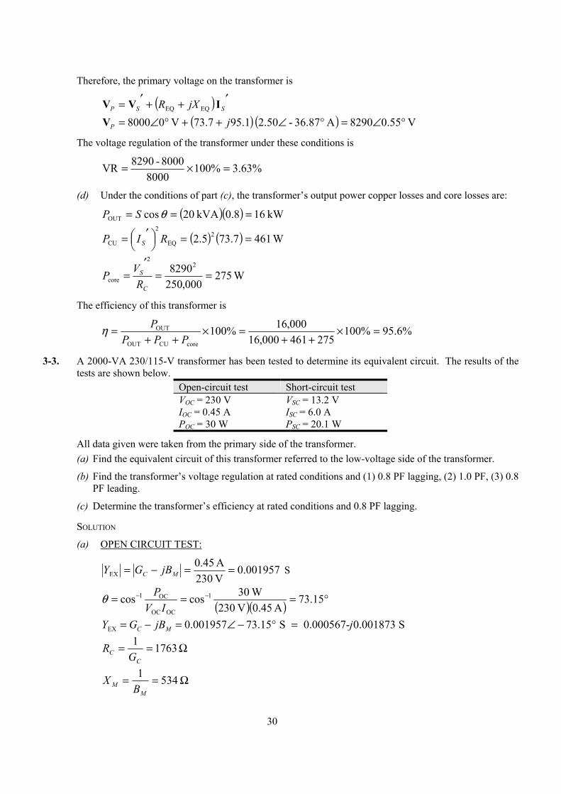
(c) To simplify the calculations, use the simplified equivalent circuit referred to the primary side of the
transformer:
32 Ω 41.7 Ω
250 kΩ
j45 Ω j50.1 Ω
j30 kΩ
The secondary current in this transformer is
A 87.3672.2A 87.36V 277
kVA 20 °−∠=°−∠=SI
The secondary current referred to the primary side is
A 87.3650.289.28
A 87.3672.2 °−∠=°−∠==′aS
SII
30
Therefore, the primary voltage on the transformer is
( ) ′++′= SSP jXR IVV EQEQ
( ) ( ) V 55.08290A 36.87-2.50 1.957.73V 08000 °∠=°∠++°∠= jPV
The voltage regulation of the transformer under these conditions is
%63.3%1008000
8000-8290VR =×=
(d) Under the conditions of part (c), the transformer’s output power copper losses and core losses are:
( )( ) kW 168.0kVA 20 cos OUT === θSP
( ) ( ) W 4617.735.2 2EQ
2
CU ==
′= RIP S
W 275000,250
829022
core ==′
=C
S
RVP
The efficiency of this transformer is
%6.95%100275461000,16
000,16%100coreCUOUT
OUT =×++
=×++
=PPP
Pη
3-3. A 2000-VA 230/115-V transformer has been tested to determine its equivalent circuit. The results of the tests are shown below.
Open-circuit test Short-circuit test VOC = 230 V VSC = 13.2 V IOC = 0.45 A ISC = 6.0 A POC = 30 W PSC = 20.1 W
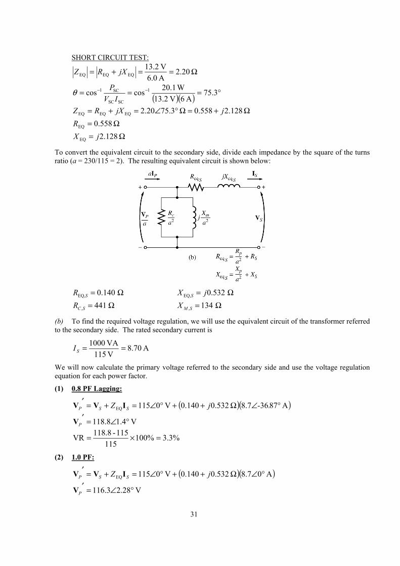
All data given were taken from the primary side of the transformer. (a) Find the equivalent circuit of this transformer referred to the low-voltage side of the transformer.
(b) Find the transformer’s voltage regulation at rated conditions and (1) 0.8 PF lagging, (2) 1.0 PF, (3) 0.8 PF leading.
(c) Determine the transformer’s efficiency at rated conditions and 0.8 PF lagging.
SOLUTION
(a) OPEN CIRCUIT TEST:
001957.0V 230A 45.0
EX ==−= MC jBGY S
( )( ) °=== −− 15.73A 45.0V 230
W 30coscos 1
OCOC
OC1
IVPθ
EX 0.001957 73.15 S 0.000567- 0.001873 SC MY G jB j= − = ∠ − ° =
Ω== 17631
CC G
R
Ω== 5341
MM B
X
31
SHORT CIRCUIT TEST:
20.2A 6.0V 13.2
EQEQEQ Ω==+= jXRZ
( )( ) °=== −− 3.75A 6V 13.2
W 0.12coscos 1
SCSC
SC1
IVPθ
Ω+=Ω°∠=+= 128.2558.0 3.7520.2EQEQEQ jjXRZ
Ω= 558.0EQR
Ω= 128.2EQ jX
To convert the equivalent circuit to the secondary side, divide each impedance by the square of the turns ratio (a = 230/115 = 2). The resulting equivalent circuit is shown below:
EQ, 0.140 SR = Ω EQ, 0.532 SX j= Ω
, 441 C SR = Ω , 134 M SX = Ω
(b) To find the required voltage regulation, we will use the equivalent circuit of the transformer referred to the secondary side. The rated secondary current is
A 70.8V 115VA 1000 ==SI
We will now calculate the primary voltage referred to the secondary side and use the voltage regulation equation for each power factor.
(1) 0.8 PF Lagging:
( )( )A 87368.7 0.532 0.140 V 0115EQ °∠Ω++°∠=+=′ .-jZ SSP IVV
V 4.18.118 °∠=′PV
%3.3%100115
115-118.8VR =×=
(2) 1.0 PF:
( )( )A 08.7 0.532 0.140 V 0115EQ °∠Ω++°∠=+=′ jZ SSP IVV
V 28.23.116 °∠=′PV
32
%1.1%100115
115-116.3VR =×=
(3) 0.8 PF Leading:
( )( )A 87368.7 0.532 0.140 V 0115EQ °∠Ω++°∠=+=′ .jZ SSP IVV
V 24.23.113 °∠=′PV
%5.1%100115
115-113.3VR −=×=
(c) At rated conditions and 0.8 PF lagging, the output power of this transformer is
( )( )( ) W 8008.0A 7.8V 115 cos OUT === θSS IVP
The copper and core losses of this transformer are
( ) ( ) W 6.10 140.0A 7.8 2EQ,
2CU =Ω== SS RIP
( ) W 0.32
441V 8.118
2
2
core =Ω
=
′
=C
P
R
VP
Therefore the efficiency of this transformer at these conditions is
%9.94W 32.0 W 10.6 W 800
W 800%100coreCUOUT
OUT =++
=×++
=PPP
Pη
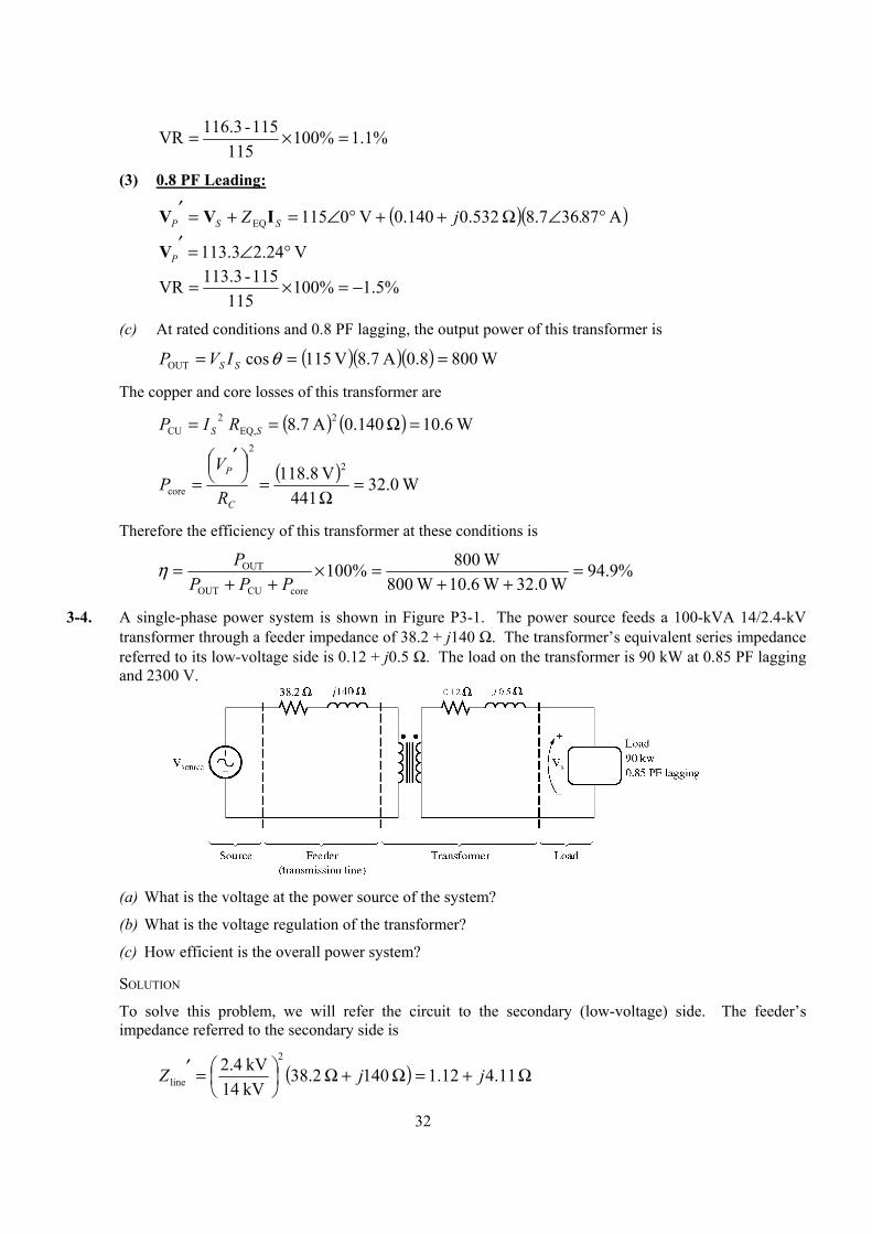
3-4. A single-phase power system is shown in Figure P3-1. The power source feeds a 100-kVA 14/2.4-kV transformer through a feeder impedance of 38.2 + j140 Ω. The transformer’s equivalent series impedance referred to its low-voltage side is 0.12 + j0.5 Ω. The load on the transformer is 90 kW at 0.85 PF lagging and 2300 V.
(a) What is the voltage at the power source of the system?
(b) What is the voltage regulation of the transformer?
(c) How efficient is the overall power system?
SOLUTION
To solve this problem, we will refer the circuit to the secondary (low-voltage) side. The feeder’s impedance referred to the secondary side is
( ) Ω+=Ω+Ω
=′ 11.412.1 140 2.38
kV 14kV 4.2 2
line jjZ
33
The secondary current SI is given by
( )( ) A 48.439.0V 2300
kW 90 ==SI
A 8.2548.43 °−∠=SI
(a) The voltage at the power source of this system (referred to the secondary side) is
EQlinesource ZZ SSS IIVV +′+=′
( ) ( ) ( ) ( )source 2300 0 V 43.48 25.8 A 1.12 4.11 43.48 25.8 A 0.12 0.5 j j′ = ∠ ° + ∠ − ° + Ω + ∠ − ° + ΩV
V 7.32441source °∠=′V
Therefore, the voltage at the power source is
( ) kV 7.324.14kV 2.4kV 14V 7.32441source °∠=°∠=V
(b) To find the voltage regulation of the transformer, we must find the voltage at the primary side of the transformer (referred to the secondary side) under full load conditions:
EQZSSP IVV +=′
( )( ) V 43.02314 5.012.0A 8.2548.43V 02300 °∠=Ω+°−∠+°∠=′ jPV
There is a voltage drop of 14 V under these load conditions. Therefore the voltage regulation of the transformer is
%6.0%1002300
2300-2314VR =×=
(c) The power supplied to the load is POUT = 90 kW. The power supplied by the source is
( )( ) kW 37.9229.5 cos A 48.43V 2441 cos sourceIN =°=′= θSIVP
Therefore, the efficiency of the power system is
%4.97%100kW 92.37
kW 90%100IN
OUT =×=×=P
Pη
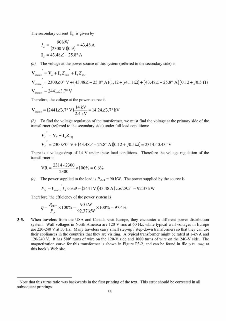
3-5. When travelers from the USA and Canada visit Europe, they encounter a different power distribution system. Wall voltages in North America are 120 V rms at 60 Hz, while typical wall voltages in Europe are 220-240 V at 50 Hz. Many travelers carry small step-up / step-down transformers so that they can use their appliances in the countries that they are visiting. A typical transformer might be rated at 1-kVA and 120/240 V. It has 5001 turns of wire on the 120-V side and 1000 turns of wire on the 240-V side. The magnetization curve for this transformer is shown in Figure P3-2, and can be found in file p32.mag at this book’s Web site.
1 Note that this turns ratio was backwards in the first printing of the text. This error should be corrected in all subsequent printings.
34
(a) Suppose that this transformer is connected to a 120-V, 60 Hz power source with no load
connected to the 240-V side. Sketch the magnetization current that would flow in the transformer. (Use MATLAB to plot the current accurately, if it is available.) What is the rms amplitude of the magnetization current? What percentage of full-load current is the magnetization current?
(b) Now suppose that this transformer is connected to a 240-V, 50 Hz power source with no load connected to the 120-V side. Sketch the magnetization current that would flow in the transformer. (Use MATLAB to plot the current accurately, if it is available.) What is the rms amplitude of the magnetization current? What percentage of full-load current is the magnetization current?
(c) In which case is the magnetization current a higher percentage of full-load current? Why?
SOLUTION
(a) When this transformer is connected to a 120-V 60 Hz source, the flux in the core will be given by the equation
cos )( tN
VtP
M ωω
φ −= (3-104)
The magnetization current required for any given flux level can be found from Figure P3-2, or alternately from the equivalent table in file p32.mag. The MATLAB program shown below calculates the flux level at each time, the corresponding magnetization current, and the rms value of the magnetization current.
% M-file: prob3_5a.m% M-file to calculate and plot the magnetization% current of a 120/240 transformer operating at

35
% 120 volts and 60 Hz. This program also% calculates the rms value of the mag. current.
% Load the magnetization curve. It is in two% columns, with the first column being mmf and% the second column being flux.load p32.mag;mmf_data = p32(:,1);flux_data = p32(:,2);
% Initialize valuesS = 1000; % Apparent power (VA)Vrms = 120; % Rms voltage (V)VM = Vrms * sqrt(2); % Max voltage (V)NP = 500; % Primary turns
% Calculate angular velocity for 60 Hzfreq = 60; % Freq (Hz)w = 2 * pi * freq;
% Calculate flux versus timetime = 0:1/3000:1/30; % 0 to 1/30 secflux = -VM/(w*NP) * cos(w .* time);
% Calculate the mmf corresponding to a given flux% using the MATLAB interpolation function.mmf = interp1(flux_data,mmf_data,flux);
% Calculate the magnetization currentim = mmf / NP;
% Calculate the rms value of the currentirms = sqrt(sum(im.^2)/length(im));disp(['The rms current at 120 V and 60 Hz is ', num2str(irms)]);
% Calculate the full-load currenti_fl = S / Vrms;
% Calculate the percentage of full-load currentpercnt = irms / i_fl * 100;disp(['The magnetization current is ' num2str(percnt) ...
'% of full-load current.']);
% Plot the magnetization current.figure(1)plot(time,im);title ('\bfMagnetization Current at 120 V and 60 Hz');xlabel ('\bfTime (s)');ylabel ('\bf\itI_m \rm(A)');axis([0 0.04 -0.5 0.5]);grid on;
When this program is executed, the results are
» prob3_5aThe rms current at 120 V and 60 Hz is 0.31863The magnetization current is 3.8236% of full-load current.
36
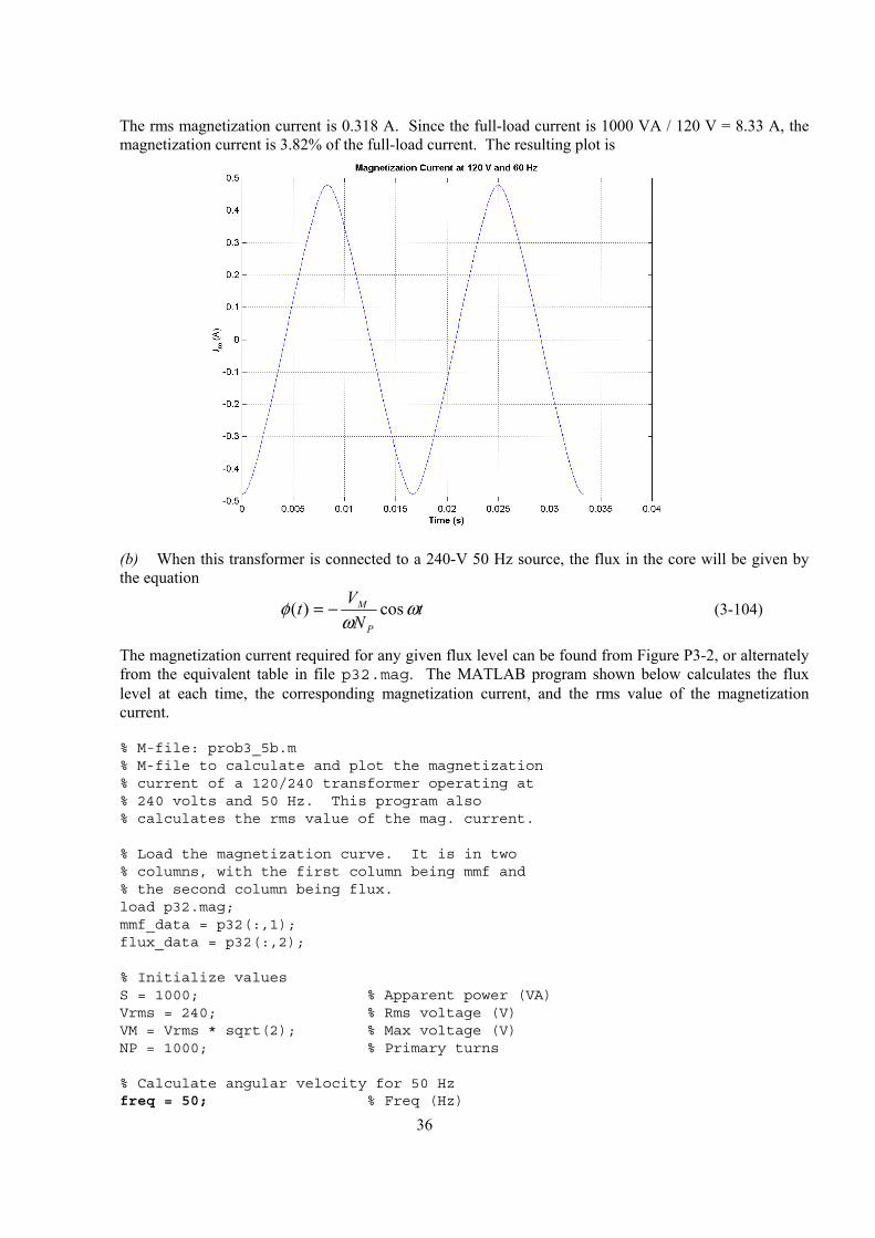
The rms magnetization current is 0.318 A. Since the full-load current is 1000 VA / 120 V = 8.33 A, the magnetization current is 3.82% of the full-load current. The resulting plot is
(b) When this transformer is connected to a 240-V 50 Hz source, the flux in the core will be given by
the equation
cos )( tN
VtP
M ωω
φ −= (3-104)
The magnetization current required for any given flux level can be found from Figure P3-2, or alternately from the equivalent table in file p32.mag. The MATLAB program shown below calculates the flux level at each time, the corresponding magnetization current, and the rms value of the magnetization current.
% M-file: prob3_5b.m% M-file to calculate and plot the magnetization% current of a 120/240 transformer operating at% 240 volts and 50 Hz. This program also% calculates the rms value of the mag. current.
% Load the magnetization curve. It is in two% columns, with the first column being mmf and% the second column being flux.load p32.mag;mmf_data = p32(:,1);flux_data = p32(:,2);
% Initialize valuesS = 1000; % Apparent power (VA)Vrms = 240; % Rms voltage (V)VM = Vrms * sqrt(2); % Max voltage (V)NP = 1000; % Primary turns
% Calculate angular velocity for 50 Hzfreq = 50; % Freq (Hz)

37
w = 2 * pi * freq;
% Calculate flux versus timetime = 0:1/2500:1/25; % 0 to 1/25 secflux = -VM/(w*NP) * cos(w .* time);
% Calculate the mmf corresponding to a given flux% using the MATLAB interpolation function.mmf = interp1(flux_data,mmf_data,flux);
% Calculate the magnetization currentim = mmf / NP;
% Calculate the rms value of the currentirms = sqrt(sum(im.^2)/length(im));disp(['The rms current at 50 Hz is ', num2str(irms)]);
% Calculate the full-load currenti_fl = S / Vrms;
% Calculate the percentage of full-load currentpercnt = irms / i_fl * 100;disp(['The magnetization current is ' num2str(percnt) ...
'% of full-load current.']);
% Plot the magnetization current.figure(1);plot(time,im);title ('\bfMagnetization Current at 240 V and 50 Hz');xlabel ('\bfTime (s)');ylabel ('\bf\itI_m \rm(A)');axis([0 0.04 -0.5 0.5]);grid on;
When this program is executed, the results are
» prob3_5bThe rms current at 50 Hz is 0.22973The magnetization current is 5.5134% of full-load current.
The rms magnetization current is 0.318 A. Since the full-load current is 1000 VA / 240 V = 4.17 A, the magnetization current is 5.51% of the full-load current. The resulting plot is shown below.

38
(c) The magnetization current is a higher percentage of the full-load current for the 50 Hz case than for
the 60 Hz case. This is true because the peak flux is higher for the 50 Hz waveform, driving the core further into saturation.
3-6. A 15-kVA 8000/230-V distribution transformer has an impedance referred to the primary of 80 + j300 Ω. The components of the excitation branch referred to the primary side are Ω= k 350CR and Ω= k 70MX .
(a) If the primary voltage is 7967 V and the load impedance is ZL = 3.2 + j1.5 Ω, what is the secondary voltage of the transformer? What is the voltage regulation of the transformer?
(b) If the load is disconnected and a capacitor of –j3.5 Ω is connected in its place, what is the secondary voltage of the transformer? What is its voltage regulation under these conditions?
SOLUTION
(a) The easiest way to solve this problem is to refer all components to the primary side of the transformer. The turns ratio is a = 8000/230 = 34.78. Thus the load impedance referred to the primary side is
( ) ( ) Ω+=Ω+=′ 18153871 5.12.378.34 2 jjZL
The referred secondary current is
( ) ( ) A 2.2878.1 28.24481
V 07967 18153871 30080
V 07967 °−∠=Ω°∠
°∠=Ω++Ω+
°∠=′jjSI
and the referred secondary voltage is
( ) ( )1.78 28.2 A 3871 1815 7610 3.1 VS S LZ j′ ′ ′= = ∠ − ° + Ω = ∠ − °V I
The actual secondary voltage is thus
V 1.38.21878.34
V 1.37610 °−∠=°−∠=′
=aS
SVV
39
The voltage regulation is
%7.4%1007610
7610-7967VR =×=
(b) As before, the easiest way to solve this problem is to refer all components to the primary side of the transformer. The turns ratio is again a = 34.78. Thus the load impedance referred to the primary side is
( ) ( ) Ω−=Ω−=′ 4234 5.378.34 2 jjZL
The referred secondary current is
( ) ( ) A 8.88025.2 8.88-9353
V 07967 4234 30080
V 07967 °∠=Ω°∠
°∠=Ω−+Ω+
°∠=′jjSI
and the referred secondary voltage is
( ) ( )2.25 88.8 A 4234 8573 1.2 VS S LZ j′ ′ ′= = ∠ ° − Ω = ∠ − °V I
The actual secondary voltage is thus
V 2.15.24678.34
V 2.18573 °−∠=°−∠=′
=aS
SVV
The voltage regulation is
%07.7%1008573
8573-7967VR −=×=
3-7. A 5000-kVA 230/13.8-kV single-phase power transformer has a per-unit resistance of 1 percent and a per-unit reactance of 5 percent (data taken from the transformer’s nameplate). The open-circuit test performed on the low-voltage side of the transformer yielded the following data:
VOC kV= 138. A 1.15OC =I kW 9.44OC =P
(a) Find the equivalent circuit referred to the low-voltage side of this transformer.
(b) If the voltage on the secondary side is 13.8 kV and the power supplied is 4000 kW at 0.8 PF lagging, find the voltage regulation of the transformer. Find its efficiency.
SOLUTION
(a) The open-circuit test was performed on the low-voltage side of the transformer, so it can be used to directly find the components of the excitation branch relative to the low-voltage side.
EX15.1 A 0.0010942 13.8 kVC MY G jB= − = =
( )( ) °=== −− 56.77A 5.11kV 13.8
kW 4.94coscos 1
OCOC
OC1
IVPθ
EX 0.0010942 77.56 S 0.0002358 0.0010685 SC MY G jB j= − = ∠ − ° = −
Ω== 42401
CC G
R
Ω== 9361
MM B
X
The base impedance of this transformer referred to the secondary side is
40
( ) Ω=== 09.38
kVA 5000kV 8.13 2
base
2base
base SVZ
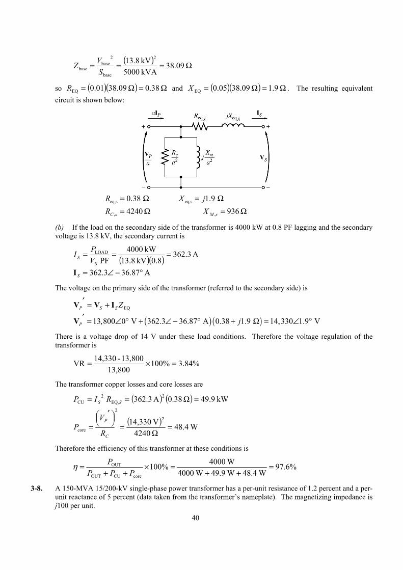
so ( )( ) Ω=Ω= 38.0 09.3801.0EQR and ( )( ) Ω=Ω= 9.1 09.3805.0EQX . The resulting equivalent circuit is shown below:
eq,s 0.38 R = Ω eq,s 1.9 X j= Ω
Ω= 4240,sCR Ω= 936,sMX
(b) If the load on the secondary side of the transformer is 4000 kW at 0.8 PF lagging and the secondary voltage is 13.8 kV, the secondary current is
( )( ) A 3.3628.0kV 13.8
kW 4000 PF
LOAD ===S
S VPI
A 87.363.362 °−∠=SI
The voltage on the primary side of the transformer (referred to the secondary side) is
EQZSSP IVV +=′
( ) ( )13,800 0 V 362.3 36.87 A 0.38 1.9 14,330 1.9 VP j′ = ∠ ° + ∠ − ° + Ω = ∠ °V
There is a voltage drop of 14 V under these load conditions. Therefore the voltage regulation of the transformer is
%84.3%10013,800
13,800-14,330VR =×=
The transformer copper losses and core losses are
( ) ( ) kW 9.49 38.0A 62.33 2EQ,
2CU =Ω== SS RIP
( ) W 4.48
4240V 4,3301
2
2
core =Ω
=
′
=C
P
R
VP
Therefore the efficiency of this transformer at these conditions is
%6.97W 48.4 W 49.9 W 4000
W 4000%100coreCUOUT
OUT =++
=×++
=PPP
Pη
3-8. A 150-MVA 15/200-kV single-phase power transformer has a per-unit resistance of 1.2 percent and a per-unit reactance of 5 percent (data taken from the transformer’s nameplate). The magnetizing impedance is j100 per unit.
41
(a) Find the equivalent circuit referred to the low-voltage side of this transformer.
(b) Calculate the voltage regulation of this transformer for a full-load current at power factor of 0.8 lagging.
(c) Assume that the primary voltage of this transformer is a constant 15 kV, and plot the secondary voltage as a function of load current for currents from no-load to full-load. Repeat this process for power factors of 0.8 lagging, 1.0, and 0.8 leading.
SOLUTION
(a) The base impedance of this transformer referred to the primary (low-voltage) side is
( ) Ω=== 5.1
MVA501kV 51 2
base
2base
base SVZ
so ( )( ) Ω=Ω= 018.0 .51012.0EQR
( )( ) Ω=Ω= 075.0 .5105.0EQX
( )( ) Ω=Ω= 150 .51100MX
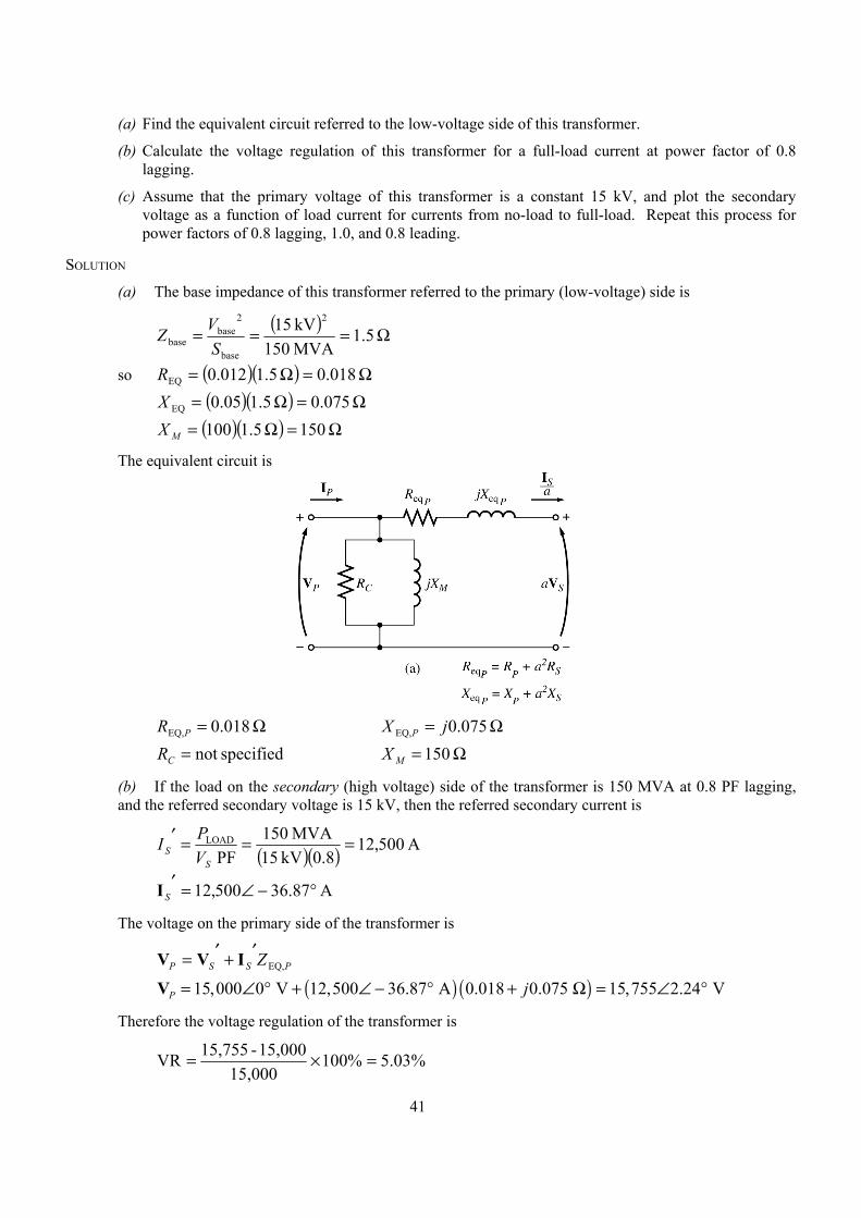
The equivalent circuit is
Ω= 018.0EQ,PR Ω= 075.0EQ, jX P
specifiednot =CR Ω= 150MX
(b) If the load on the secondary (high voltage) side of the transformer is 150 MVA at 0.8 PF lagging, and the referred secondary voltage is 15 kV, then the referred secondary current is
( )( ) A 500,128.0kV 15
MVA501 PF
LOAD ===′S
S VPI
A 87.36500,12 °−∠=′SI
The voltage on the primary side of the transformer is
PSSP ZEQ,′+′= IVV
( ) ( )15,000 0 V 12,500 36.87 A 0.018 0.075 15,755 2.24 VP j= ∠ ° + ∠ − ° + Ω = ∠ °V
Therefore the voltage regulation of the transformer is
%03.5%10015,000
15,000-15,755VR =×=

42
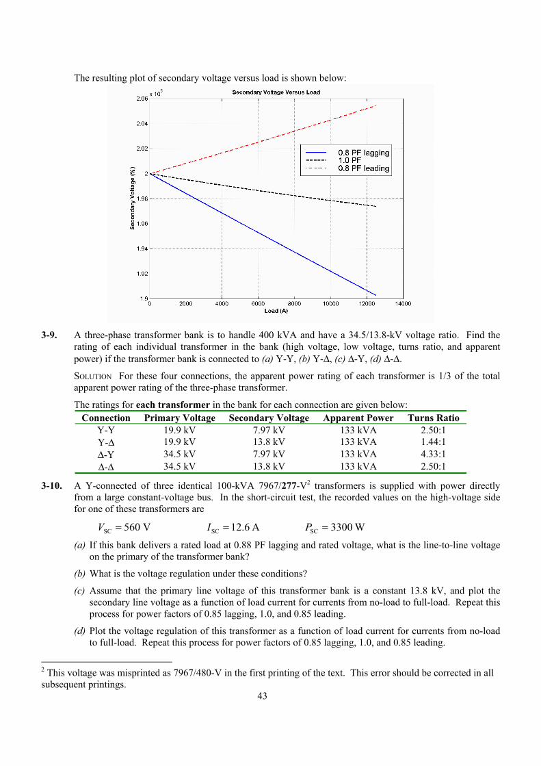
(c) This problem is repetitive in nature, and is ideally suited for MATLAB. A program to calculate the secondary voltage of the transformer as a function of load is shown below:
% M-file: prob3_8.m% M-file to calculate and plot the secondary voltage% of a transformer as a function of load for power% factors of 0.8 lagging, 1.0, and 0.8 leading.% These calculations are done using an equivalent% circuit referred to the primary side.
% Define values for this transformerVP = 15000; % Primary voltage (V)amps = 0:125:12500; % Current values (A)Req = 0.018; % Equivalent R (ohms)Xeq = 0.075; % Equivalent X (ohms)
% Calculate the current values for the three% power factors. The first row of I contains% the lagging currents, the second row contains% the unity currents, and the third row contains% the leading currents.I(1,:) = amps .* ( 0.8 - j*0.6); % LaggingI(2,:) = amps .* ( 1.0 ); % UnityI(3,:) = amps .* ( 0.8 + j*0.6); % Leading
% Calculate VS referred to the primary side% for each current and power factor.aVS = VP - (Req.*I + j.*Xeq.*I);
% Refer the secondary voltages back to the% secondary side using the turns ratio.VS = aVS * (200/15);
% Plot the secondary voltage versus loadplot(amps,abs(VS(1,:)),'b-','LineWidth',2.0);hold on;plot(amps,abs(VS(2,:)),'k--','LineWidth',2.0);plot(amps,abs(VS(3,:)),'r-.','LineWidth',2.0);title ('\bfSecondary Voltage Versus Load');xlabel ('\bfLoad (A)');ylabel ('\bfSecondary Voltage (%)');legend('0.8 PF lagging','1.0 PF','0.8 PF leading');grid on;hold off;
43
The resulting plot of secondary voltage versus load is shown below:
3-9. A three-phase transformer bank is to handle 400 kVA and have a 34.5/13.8-kV voltage ratio. Find the
rating of each individual transformer in the bank (high voltage, low voltage, turns ratio, and apparent power) if the transformer bank is connected to (a) Y-Y, (b) Y-∆, (c) ∆-Y, (d) ∆-∆.
SOLUTION For these four connections, the apparent power rating of each transformer is 1/3 of the total apparent power rating of the three-phase transformer.
The ratings for each transformer in the bank for each connection are given below: Connection Primary Voltage Secondary Voltage Apparent Power Turns Ratio
Y-Y 19.9 kV 7.97 kV 133 kVA 2.50:1 Y-∆ 19.9 kV 13.8 kV 133 kVA 1.44:1 ∆-Y 34.5 kV 7.97 kV 133 kVA 4.33:1 ∆-∆ 34.5 kV 13.8 kV 133 kVA 2.50:1
3-10. A Y-connected of three identical 100-kVA 7967/277-V2 transformers is supplied with power directly from a large constant-voltage bus. In the short-circuit test, the recorded values on the high-voltage side for one of these transformers are
VSC V= 560 A 6.12SC =I W 3300SC =P
(a) If this bank delivers a rated load at 0.88 PF lagging and rated voltage, what is the line-to-line voltage on the primary of the transformer bank?
(b) What is the voltage regulation under these conditions?
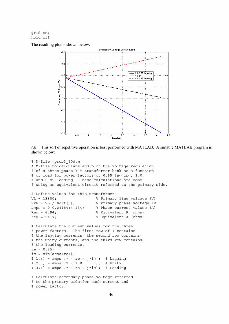
(c) Assume that the primary line voltage of this transformer bank is a constant 13.8 kV, and plot the secondary line voltage as a function of load current for currents from no-load to full-load. Repeat this process for power factors of 0.85 lagging, 1.0, and 0.85 leading.
(d) Plot the voltage regulation of this transformer as a function of load current for currents from no-load to full-load. Repeat this process for power factors of 0.85 lagging, 1.0, and 0.85 leading.
2 This voltage was misprinted as 7967/480-V in the first printing of the text. This error should be corrected in all subsequent printings.
44
SOLUTION From the short-circuit information, it is possible to determine the per-phase impedance of the transformer bank referred to the high-voltage side. The primary of this transformer is Y-connected, so the short-circuit phase voltage is
V 3.3233
SCSC, == VVφ
the short-circuit phase current is
A 6.12SC, =φI
and the power per phase is
W 11003SC
SC, == PPφ
Thus the per-phase impedance is
66.25A 12.6V 323.3
EQEQEQ Ω==+= jXRZ
( )( ) °=== −− 3.74A 2.61V 323.3
W 1001coscos 1
SCSC
SC1
IVPθ
Ω+=Ω°∠=+= 7.2494.6 3.7466.25EQEQEQ jjXRZ
Ω= 94.6EQR
Ω= 7.24EQ jX
(a) If this Y-Y transformer bank delivers rated kVA at 0.88 power factor lagging while the secondary voltage is a rated value, then each transformer delivers 33.3 kVA at a voltage of 277 V and 0.88 PF lagging. Referred to the primary side of one of the transformers, this load is equivalent to 33.3 kVA at 7967 V and 0.88 PF lagging. The equivalent current flowing in the secondary of one transformer referred to the primary side is
A 184.4V 7967
kVA 3.33, ==′SIφ
A 36.28184.4, °−∠=′SφI
The voltage on the primary side of a single transformer is thus
, , , EQ,P S S PZφ φ φ′ ′= +V V I
( ) ( ), 7967 0 V 4.184 28.36 A 6.94 24.7 8042 0.55 VP jφ = ∠ ° + ∠ − ° + Ω = ∠ °V
The line-to-line voltage on the primary of the transformer is
( ) kV 93.13V 80423 3 ,LL, === PP VV φ
(b) The voltage regulation of each transformer in the bank, and therefore of the entire transformer bank, is
%94.0%1007967
7967-8042VR =×=
45
Note: It is much easier to solve problems of this sort in the per-unit system, as we shall see in the next problem.
(c) This sort of repetitive operation is best performed with MATLAB. A suitable MATLAB program is shown below:
% M-file: prob3_10c.m% M-file to calculate and plot the secondary voltage% of a three-phase Y-Y transformer bank as a function% of load for power factors of 0.85 lagging, 1.0,% and 0.85 leading. These calculations are done using% an equivalent circuit referred to the primary side.
% Define values for this transformerVL = 13800; % Primary line voltage (V)VPP = VL / sqrt(3); % Primary phase voltage (V)amps = 0:0.04184:4.184; % Phase current values (A)Req = 6.94; % Equivalent R (ohms)Xeq = 24.7; % Equivalent X (ohms)
% Calculate the current values for the three% power factors. The first row of I contains% the lagging currents, the second row contains% the unity currents, and the third row contains% the leading currents.re = 0.85;im = sin(acos(re));I(1,:) = amps .* ( re - j*im); % LaggingI(2,:) = amps .* ( 1.0 ); % UnityI(3,:) = amps .* ( re + j*im); % Leading
% Calculate secondary phase voltage referred% to the primary side for each current and% power factor.aVSP = VPP - (Req.*I + j.*Xeq.*I);
% Refer the secondary phase voltages back to% the secondary side using the turns ratio.% Because this is a delta-connected secondary,% this is also the line voltage.VSP = aVSP * (277/7967);
% Convert secondary phase voltage to line% voltage.VSL = sqrt(3) * VSP;
% Plot the secondary voltage versus loadplot(amps,abs(VSL(1,:)),'b-','LineWidth',2.0);hold on;plot(amps,abs(VSL(2,:)),'k--','LineWidth',2.0);plot(amps,abs(VSL(3,:)),'r-.','LineWidth',2.0);title ('\bfSecondary Voltage Versus Load');xlabel ('\bfLoad (A)');ylabel ('\bfSecondary Voltage (V)');legend('0.85 PF lagging','1.0 PF','0.85 PF leading');
46
grid on;hold off;
The resulting plot is shown below:
(d) This sort of repetitive operation is best performed with MATLAB. A suitable MATLAB program is
shown below:
% M-file: prob3_10d.m% M-file to calculate and plot the voltage regulation% of a three-phase Y-Y transformer bank as a function% of load for power factors of 0.85 lagging, 1.0,% and 0.85 leading. These calculations are done% using an equivalent circuit referred to the primary side.
% Define values for this transformerVL = 13800; % Primary line voltage (V)VPP = VL / sqrt(3); % Primary phase voltage (V)amps = 0:0.04184:4.184; % Phase current values (A)Req = 6.94; % Equivalent R (ohms)Xeq = 24.7; % Equivalent X (ohms)
% Calculate the current values for the three% power factors. The first row of I contains% the lagging currents, the second row contains% the unity currents, and the third row contains% the leading currents.re = 0.85;im = sin(acos(re));I(1,:) = amps .* ( re - j*im); % LaggingI(2,:) = amps .* ( 1.0 ); % UnityI(3,:) = amps .* ( re + j*im); % Leading
% Calculate secondary phase voltage referred% to the primary side for each current and% power factor.
47
aVSP = VPP - (Req.*I + j.*Xeq.*I);
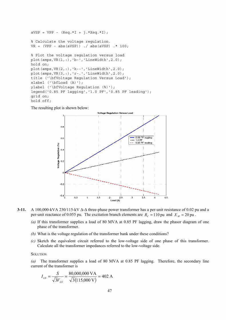
% Calculate the voltage regulation.VR = (VPP - abs(aVSP)) ./ abs(aVSP) .* 100;
% Plot the voltage regulation versus loadplot(amps,VR(1,:),'b-','LineWidth',2.0);hold on;plot(amps,VR(2,:),'k--','LineWidth',2.0);plot(amps,VR(3,:),'r-.','LineWidth',2.0);title ('\bfVoltage Regulation Versus Load');xlabel ('\bfLoad (A)');ylabel ('\bfVoltage Regulation (%)');legend('0.85 PF lagging','1.0 PF','0.85 PF leading');grid on;hold off;
The resulting plot is shown below:
3-11. A 100,000-kVA 230/115-kV ∆-∆ three-phase power transformer has a per-unit resistance of 0.02 pu and a
per-unit reactance of 0.055 pu. The excitation branch elements are pu 110=CR and pu 20=MX .
(a) If this transformer supplies a load of 80 MVA at 0.85 PF lagging, draw the phasor diagram of one phase of the transformer.
(b) What is the voltage regulation of the transformer bank under these conditions?
(c) Sketch the equivalent circuit referred to the low-voltage side of one phase of this transformer. Calculate all the transformer impedances referred to the low-voltage side.
SOLUTION
(a) The transformer supplies a load of 80 MVA at 0.85 PF lagging. Therefore, the secondary line current of the transformer is
( ) A 402V 000,1153
VA 000,000,803
===LS
LS VSI
48
The base value of the secondary line current is
( ) A 502V 000,1153VA 000,000,100
3 base,
basebase, ===
LSLS V
SI
so the per-unit secondary current is
( ) °−∠=∠== − 8.318.085.0cosA 502A 402 1
pu,pu,
LS
LSLS I
II
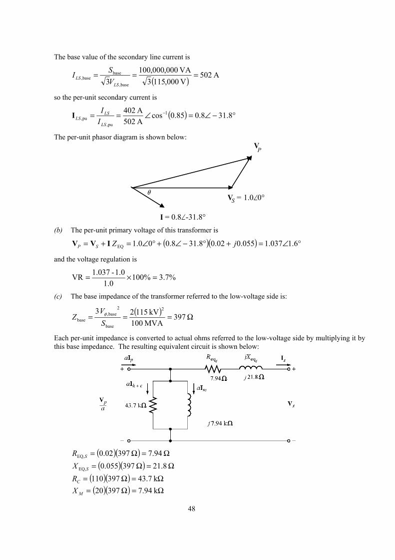
The per-unit phasor diagram is shown below:
I = 0.8∠-31.8°
V = 1.0∠0°S
VP
θ
(b) The per-unit primary voltage of this transformer is
( )( ) °∠=+°−∠+°∠=+= 6.1037.1055.002.08.318.000.1 EQ jZSP IVV
and the voltage regulation is
%7.3%1001.0
1.0-1.037VR =×=
(c) The base impedance of the transformer referred to the low-voltage side is:
( ) Ω=== 397
MVA100kV 1152 3 2
base
2base,
base SV
Z φ
Each per-unit impedance is converted to actual ohms referred to the low-voltage side by multiplying it by this base impedance. The resulting equivalent circuit is shown below:
( )( ) Ω=Ω= 94.7 39702.0EQ,SR
( )( ) Ω=Ω= 8.21 397055.0EQ,SX
( )( ) Ω=Ω= k 7.43 397110CR ( )( ) Ω=Ω= k 94.7 39720MX
49
3-12. An autotransformer is used to connect a 12.6-kV distribution line to a 13.8-kV distribution line. It must be capable of handling 2000 kVA. There are three phases, connected Y-Y with their neutrals solidly grounded. (a) What must the N NC / SE turns ratio be to accomplish this connection?
(b) How much apparent power must the windings of each autotransformer handle?
(c) If one of the autotransformers were reconnected as an ordinary transformer, what would its ratings be?
SOLUTION
(a) The transformer is connected Y-Y, so the primary and secondary phase voltages are the line voltages divided by 3 . The turns ratio of each autotransformer is given by
3kV/ 12.63kV/ 8.13SE =+=
C
C
L
H
NNN
VV
CC NNN 8.13 6.12 6.12 SE =+ CNN 2.1 6.12 SE =
Therefore, SE/ NNC = 10.5.
(b) The power advantage of this autotransformer is
5.115.10SEIO =+=+=C
CC
C
C
W NNN
NNN
SS
so 1/11.5 of the power in each transformer goes through the windings. Since 1/3 of the total power is associated with each phase, the windings in each autotransformer must handle
( )( ) kVA 585.113
kVA 2000 ==WS
(c) The voltages across each phase of the autotransformer are 13.8 kV / 3 = 7967 V and 12.6 kV / 3 = 7275 V. The voltage across the common winding ( CN ) is 7275 kV, and the voltage across the series winding ( SEN ) is 7967 kV – 7275 kV = 692 V. Therefore, a single phase of the autotransformer connected as an ordinary transformer would be rated at 7275/692 V and 58 kVA.
3-13. A 12.4-kV single-phase generator supplies power to a load through a transmission line. The load’s impedance is Zload = ∠ °500 3687. Ω , and the transmission line’s impedance is Ω°∠= 6060lineZ .
50
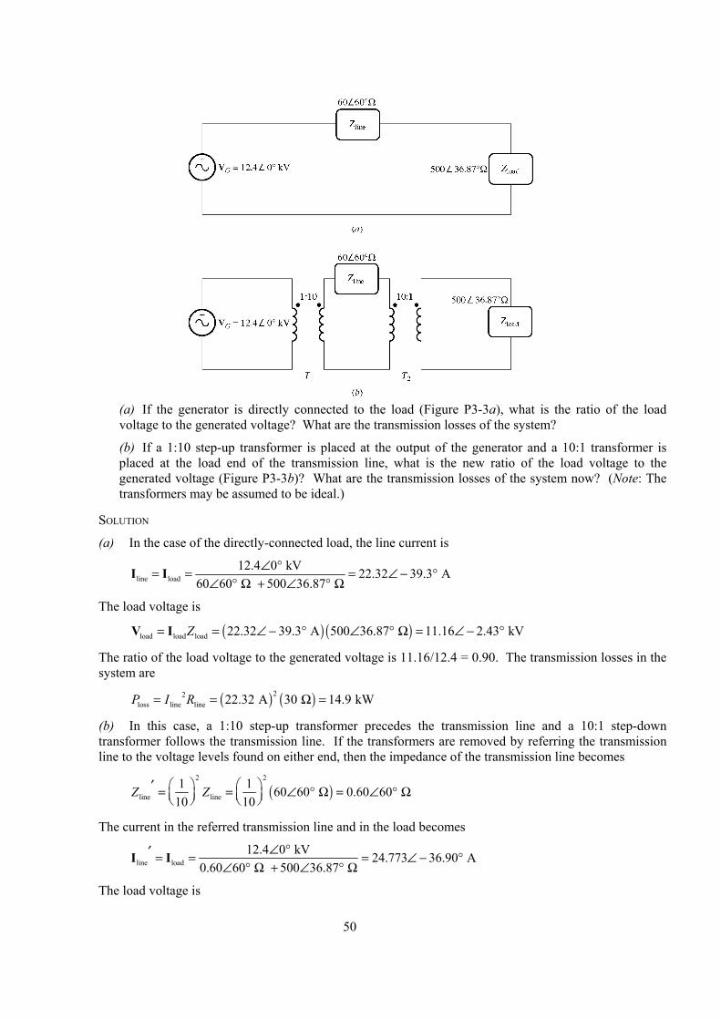
(a) If the generator is directly connected to the load (Figure P3-3a), what is the ratio of the load
voltage to the generated voltage? What are the transmission losses of the system?
(b) If a 1:10 step-up transformer is placed at the output of the generator and a 10:1 transformer is placed at the load end of the transmission line, what is the new ratio of the load voltage to the generated voltage (Figure P3-3b)? What are the transmission losses of the system now? (Note: The transformers may be assumed to be ideal.)
SOLUTION
(a) In the case of the directly-connected load, the line current is
line load12.4 0 kV 22.32 39.3 A
60 60 500 36.87 ∠ °= = = ∠ − °
∠ ° Ω + ∠ ° ΩI I
The load voltage is
( ) ( )load load load 22.32 39.3 A 500 36.87 11.16 2.43 kVZ= = ∠ − ° ∠ ° Ω = ∠ − °V I
The ratio of the load voltage to the generated voltage is 11.16/12.4 = 0.90. The transmission losses in the system are
( ) ( )22loss line line 22.32 A 30 14.9 kWP I R= = Ω =
(b) In this case, a 1:10 step-up transformer precedes the transmission line and a 10:1 step-down transformer follows the transmission line. If the transformers are removed by referring the transmission line to the voltage levels found on either end, then the impedance of the transmission line becomes
( )2 2
line line1 1 60 60 0.60 60
10 10Z Z ′ = = ∠ ° Ω = ∠ ° Ω
The current in the referred transmission line and in the load becomes
line load12.4 0 kV 24.773 36.90 A
0.60 60 500 36.87 ∠ °′ = = = ∠ − °
∠ ° Ω + ∠ ° ΩI I
The load voltage is
51
( ) ( )load load load 24.773 36.90 A 500 36.87 12.386 0.03 kVZ= = ∠ − ° ∠ ° Ω = ∠ − °V I
The ratio of the load voltage to the generated voltage is 12.386/12.4 = 0.999. Also, the transmission losses in the system are reduced. The current in the transmission line is
( )line load1 1 24.77 A 2.477 A
10 10I I = = =
and the losses in the transmission line are
( ) ( )22loss line line 2.477 A 30 184 WP I R= = Ω =
Transmission losses have decreased by a factor of more than 80!
3-14. A 5000-VA 480/120-V conventional transformer is to be used to supply power from a 600-V source to a 120-V load. Consider the transformer to be ideal, and assume that all insulation can handle 600 V. (a) Sketch the transformer connection that will do the required job.
(b) Find the kilovoltampere rating of the transformer in the configuration.
(c) Find the maximum primary and secondary currents under these conditions.
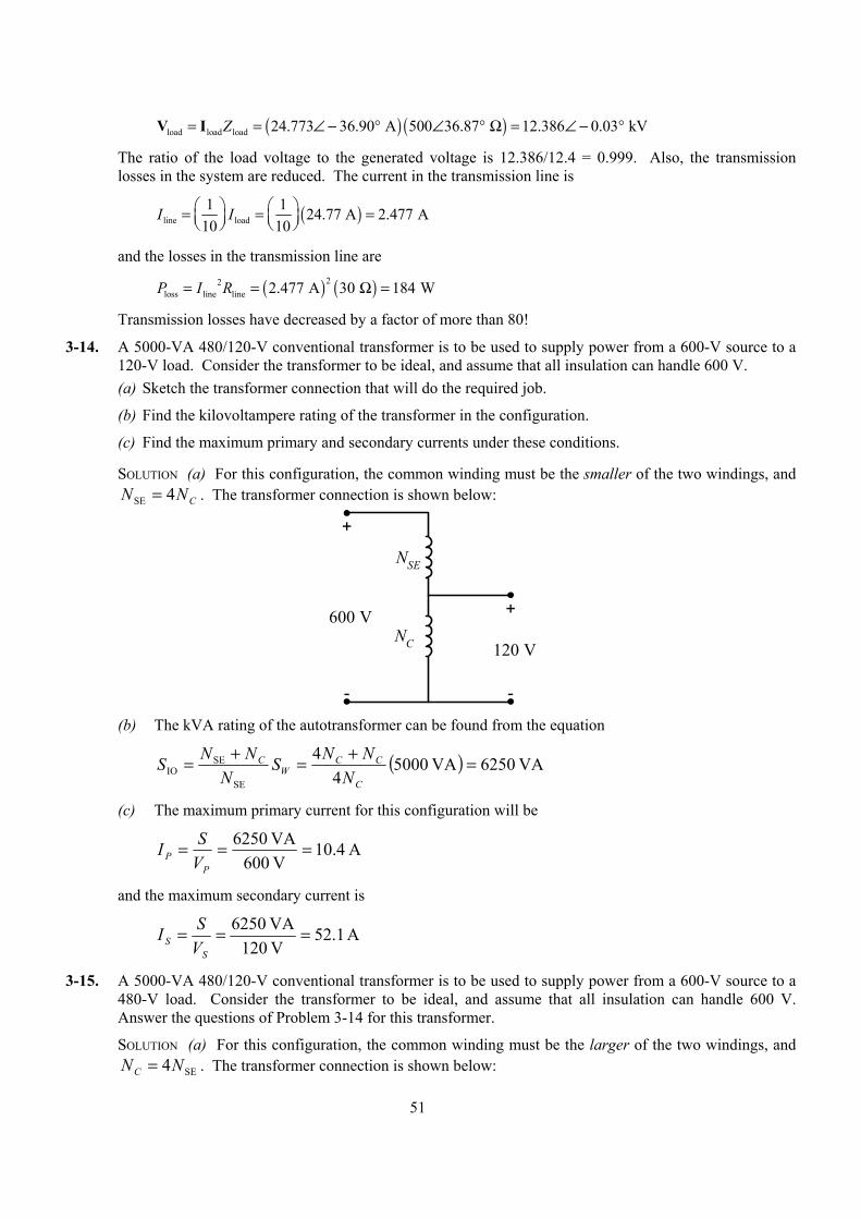
SOLUTION (a) For this configuration, the common winding must be the smaller of the two windings, and CNN 4SE = . The transformer connection is shown below:
+
-
+
-
120 V
600 VNC
NSE
(b) The kVA rating of the autotransformer can be found from the equation
( ) VA 6250VA 50004
4
SE
SEIO =+=+=
C
CCW
C
NNNS
NNNS
(c) The maximum primary current for this configuration will be
A 4.10V 600VA 6250 ===
PP V
SI
and the maximum secondary current is
A 1.52V 120VA 6250 ===
SS V
SI
3-15. A 5000-VA 480/120-V conventional transformer is to be used to supply power from a 600-V source to a 480-V load. Consider the transformer to be ideal, and assume that all insulation can handle 600 V. Answer the questions of Problem 3-14 for this transformer.
SOLUTION (a) For this configuration, the common winding must be the larger of the two windings, and SE4NNC = . The transformer connection is shown below:
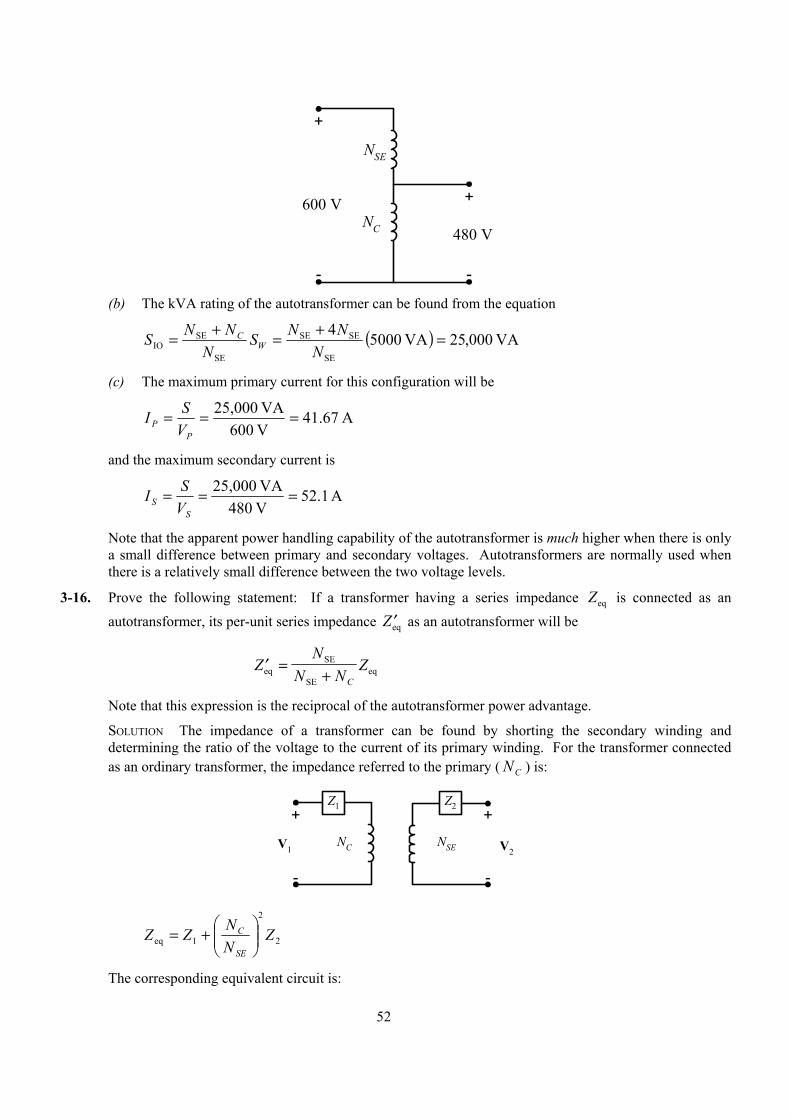
52
+
-
+
-
480 V
600 VNC
NSE
(b) The kVA rating of the autotransformer can be found from the equation
( ) VA 000,25VA 50004
SE
SESE
SE
SEIO =+=+=
NNNS
NNNS W
C
(c) The maximum primary current for this configuration will be
A 67.41V 600VA 25,000 ===
PP V
SI
and the maximum secondary current is
A 1.52V 480VA 25,000 ===
SS V
SI
Note that the apparent power handling capability of the autotransformer is much higher when there is only a small difference between primary and secondary voltages. Autotransformers are normally used when there is a relatively small difference between the two voltage levels.
3-16. Prove the following statement: If a transformer having a series impedance Zeq is connected as an autotransformer, its per-unit series impedance ′Zeq as an autotransformer will be
′ =+
ZN
N NZ
Ceq
SE
SEeq
Note that this expression is the reciprocal of the autotransformer power advantage.
SOLUTION The impedance of a transformer can be found by shorting the secondary winding and determining the ratio of the voltage to the current of its primary winding. For the transformer connected as an ordinary transformer, the impedance referred to the primary ( CN ) is:
+
-
+
-
NC NSEV1 V2
Z1 Z2
2
2
1eq ZNNZZ
SE
C
+=
The corresponding equivalent circuit is:
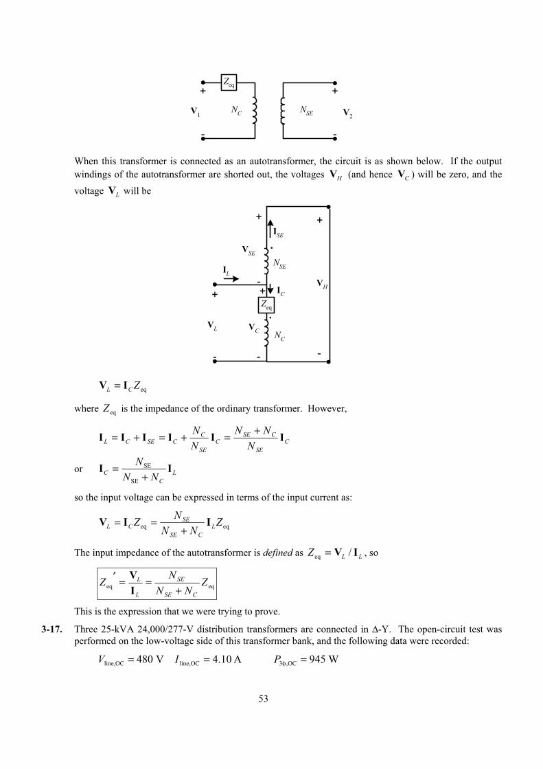
53
+
-
+
-
NC NSEV1 V2
Zeq
When this transformer is connected as an autotransformer, the circuit is as shown below. If the output
windings of the autotransformer are shorted out, the voltages HV (and hence CV ) will be zero, and the voltage LV will be
+
-
+
-
NC
NSE
VL
VH
Zeq.
.
+
-
-
+
VC
VSE
ISE
IL
IC
eqZCL IV =
where eqZ is the impedance of the ordinary transformer. However,
CSE
CSEC
SE
CCSECL N
NNNN IIIIII +=+=+=
or LC
C NNN II
+=
SE
SE
so the input voltage can be expressed in terms of the input current as:
eqeq ZNN
NZ LCSE
SECL IIV
+==
The input impedance of the autotransformer is defined as LLZ IV /eq = , so
eqeq ZNN
NZCSE
SE
L
L
+==′
IV
This is the expression that we were trying to prove.
3-17. Three 25-kVA 24,000/277-V distribution transformers are connected in ∆-Y. The open-circuit test was performed on the low-voltage side of this transformer bank, and the following data were recorded:
Vline,OC V= 480 A 10.4line,OC =I P3 ,OC Wφ = 945
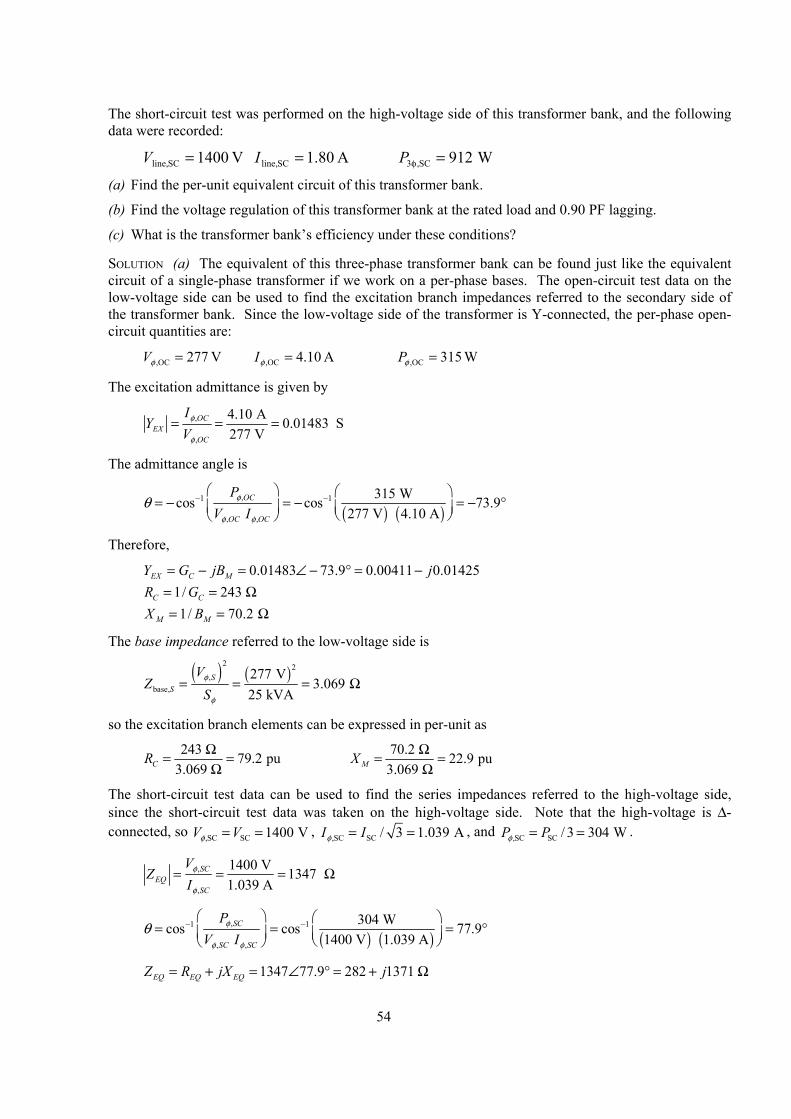
54
The short-circuit test was performed on the high-voltage side of this transformer bank, and the following data were recorded:
V 1400SCline, =V A 80.1SCline, =I P3 ,SC Wφ = 912
(a) Find the per-unit equivalent circuit of this transformer bank.
(b) Find the voltage regulation of this transformer bank at the rated load and 0.90 PF lagging.
(c) What is the transformer bank’s efficiency under these conditions?
SOLUTION (a) The equivalent of this three-phase transformer bank can be found just like the equivalent circuit of a single-phase transformer if we work on a per-phase bases. The open-circuit test data on the low-voltage side can be used to find the excitation branch impedances referred to the secondary side of the transformer bank. Since the low-voltage side of the transformer is Y-connected, the per-phase open-circuit quantities are:
V 277,OC =φV A 10.4,OC =φI W 315,OC =φP
The excitation admittance is given by
,
,
4.10 A 0.01483 S277 V
OCEX
OC
IY
Vφ
φ
= = =
The admittance angle is
( ) ( )
,1 1
, ,
315 Wcos cos 73.9 277 V 4.10 AOC
OC OC
PV I
φ
φ φ
θ − − = − = − = − °
Therefore,
0.01483 73.9 0.00411 0.01425EX C MY G jB j= − = ∠ − ° = − 1/ 243 C CR G= = Ω 1/ 70.2 M MX B= = Ω
The base impedance referred to the low-voltage side is
( ) ( )2 2
,base,
277 V3.069
25 kVAS
S
VZ
Sφ
φ
= = = Ω
so the excitation branch elements can be expressed in per-unit as
243 79.2 pu3.069 CR Ω= =
Ω 70.2 22.9 pu
3.069 MX Ω= =Ω
The short-circuit test data can be used to find the series impedances referred to the high-voltage side, since the short-circuit test data was taken on the high-voltage side. Note that the high-voltage is ∆-connected, so ,SC SC 1400 VV Vφ = = , ,SC SC / 3 1.039 AI Iφ = = , and ,SC SC / 3 304 WP Pφ = = .
,
,
1400 V 1347 1.039 A
SCEQ
SC
VZ
Iφ
φ
= = = Ω
( ) ( )
,1 1
, ,
304 Wcos cos 77.9 1400 V 1.039 ASC
SC SC
PV I
φ
φ φ
θ − − = = = °
1347 77.9 282 1371 EQ EQ EQZ R jX j= + = ∠ ° = + Ω
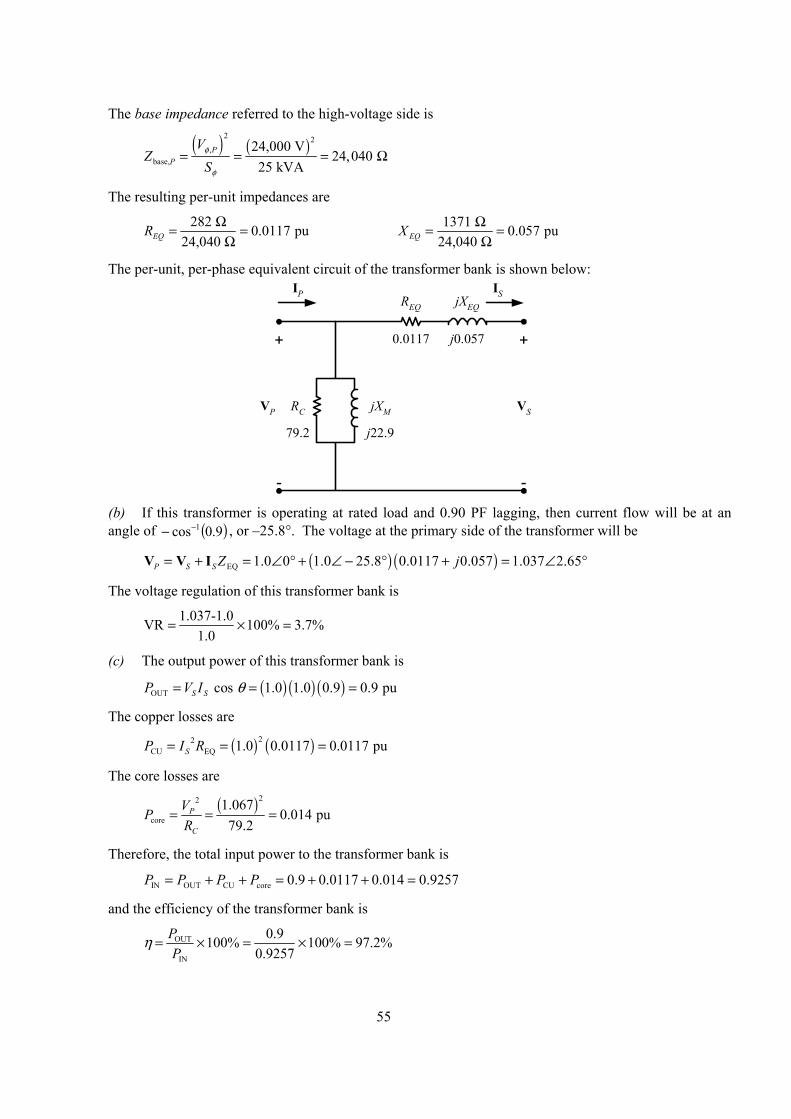
55
The base impedance referred to the high-voltage side is
( ) ( )2 2
,base,
24,000 V24,040
25 kVAP
P
VZ
Sφ
φ
= = = Ω
The resulting per-unit impedances are
282 0.0117 pu24,040 EQR Ω= =
Ω 1371 0.057 pu
24,040 EQX Ω= =Ω
The per-unit, per-phase equivalent circuit of the transformer bank is shown below:
+
-
VSVP
IS
+
-
IP
RC jXM
REQ jXEQ
0.0117 j0.057
79.2 j22.9
(b) If this transformer is operating at rated load and 0.90 PF lagging, then current flow will be at an
angle of ( )9.0cos 1−− , or –25.8°. The voltage at the primary side of the transformer will be
( ) ( )EQ 1.0 0 1.0 25.8 0.0117 0.057 1.037 2.65P S S Z j= + = ∠ ° + ∠ − ° + = ∠ °V V I
The voltage regulation of this transformer bank is
1.037-1.0VR 100% 3.7%1.0
= × =
(c) The output power of this transformer bank is
( ) ( ) ( )OUT cos 1.0 1.0 0.9 0.9 puS SP V I θ= = =
The copper losses are
( ) ( )22CU EQ 1.0 0.0117 0.0117 puSP I R= = =
The core losses are
( )22
core1.067
0.014 pu79.2
P
C
VPR
= = =
Therefore, the total input power to the transformer bank is
IN OUT CU core 0.9 0.0117 0.014 0.9257P P P P= + + = + + =
and the efficiency of the transformer bank is
OUT
IN
0.9100% 100% 97.2%0.9257
PP
η = × = × =
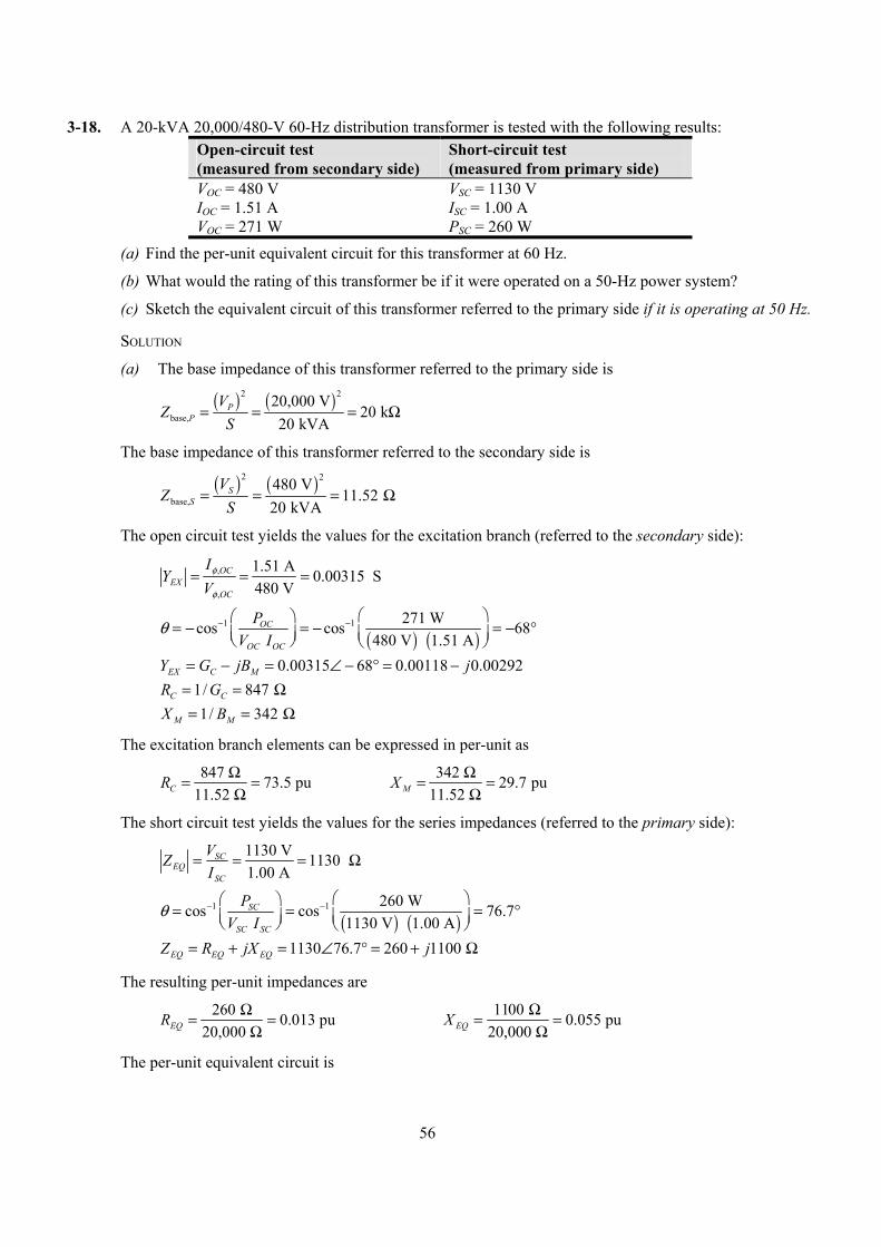
56
3-18. A 20-kVA 20,000/480-V 60-Hz distribution transformer is tested with the following results: Open-circuit test (measured from secondary side)
Short-circuit test (measured from primary side)
VOC = 480 V VSC = 1130 V IOC = 1.51 A ISC = 1.00 A VOC = 271 W PSC = 260 W
(a) Find the per-unit equivalent circuit for this transformer at 60 Hz.
(b) What would the rating of this transformer be if it were operated on a 50-Hz power system?
(c) Sketch the equivalent circuit of this transformer referred to the primary side if it is operating at 50 Hz.
SOLUTION
(a) The base impedance of this transformer referred to the primary side is
( ) ( )2 2
base,20,000 V
20 k20 kVA
PP
VZ
S= = = Ω
The base impedance of this transformer referred to the secondary side is
( ) ( )2 2
base,480 V
11.52 20 kVA
SS
VZ
S= = = Ω
The open circuit test yields the values for the excitation branch (referred to the secondary side):
,
,
1.51 A 0.00315 S480 V
OCEX
OC
IY
Vφ
φ
= = =
( ) ( )
1 1 271 Wcos cos 68 480 V 1.51 A
OC
OC OC
PV I
θ − − = − = − = − °
0.00315 68 0.00118 0.00292EX C MY G jB j= − = ∠ − ° = − 1/ 847 C CR G= = Ω 1/ 342 M MX B= = Ω
The excitation branch elements can be expressed in per-unit as
847 73.5 pu11.52 CR Ω= =
Ω 342 29.7 pu
11.52 MX Ω= =Ω
The short circuit test yields the values for the series impedances (referred to the primary side):
1130 V 1130 1.00 A
SCEQ
SC
VZI
= = = Ω
( ) ( )
1 1 260 Wcos cos 76.7 1130 V 1.00 ASC
SC SC
PV I
θ − − = = = °
1130 76.7 260 1100 EQ EQ EQZ R jX j= + = ∠ ° = + Ω
The resulting per-unit impedances are
260 0.013 pu20,000 EQR Ω= =
Ω 1100 0.055 pu
20,000 EQX Ω= =Ω
The per-unit equivalent circuit is
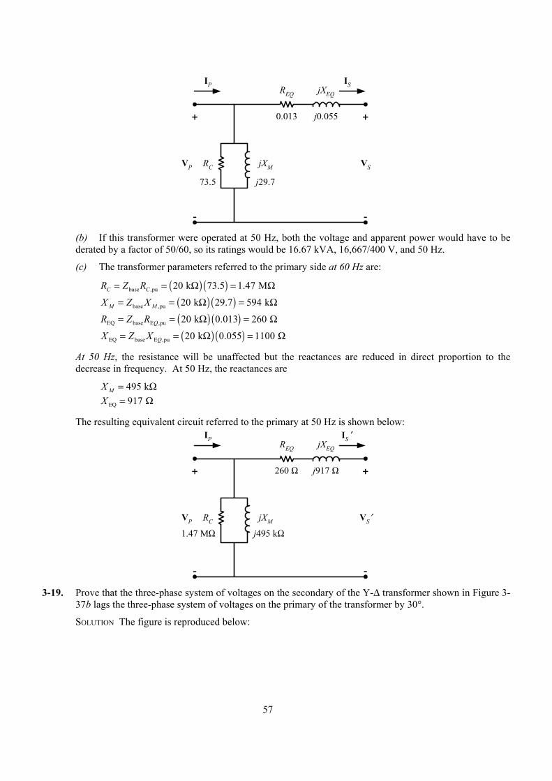
57
+
-
VSVP
IS
+
-
IP
RC jXM
REQ jXEQ
0.013 j0.055
73.5 j29.7
(b) If this transformer were operated at 50 Hz, both the voltage and apparent power would have to be
derated by a factor of 50/60, so its ratings would be 16.67 kVA, 16,667/400 V, and 50 Hz.
(c) The transformer parameters referred to the primary side at 60 Hz are:
( ) ( )base ,pu 20 k 73.5 1.47 MC CR Z R= = Ω = Ω
( ) ( )base ,pu 20 k 29.7 594 kM MX Z X= = Ω = Ω
( ) ( )EQ base E ,pu 20 k 0.013 260 QR Z R= = Ω = Ω
( ) ( )EQ base E ,pu 20 k 0.055 1100 QX Z X= = Ω = Ω
At 50 Hz, the resistance will be unaffected but the reactances are reduced in direct proportion to the decrease in frequency. At 50 Hz, the reactances are
495 kMX = Ω EQ 917 X = Ω
The resulting equivalent circuit referred to the primary at 50 Hz is shown below:
+
-
VS′VP
IS ′
+
-
IP
RC jXM
REQ jXEQ
260 Ω j917 Ω
1.47 MΩ j495 kΩ
3-19. Prove that the three-phase system of voltages on the secondary of the Y-∆ transformer shown in Figure 3-
37b lags the three-phase system of voltages on the primary of the transformer by 30°.
SOLUTION The figure is reproduced below:
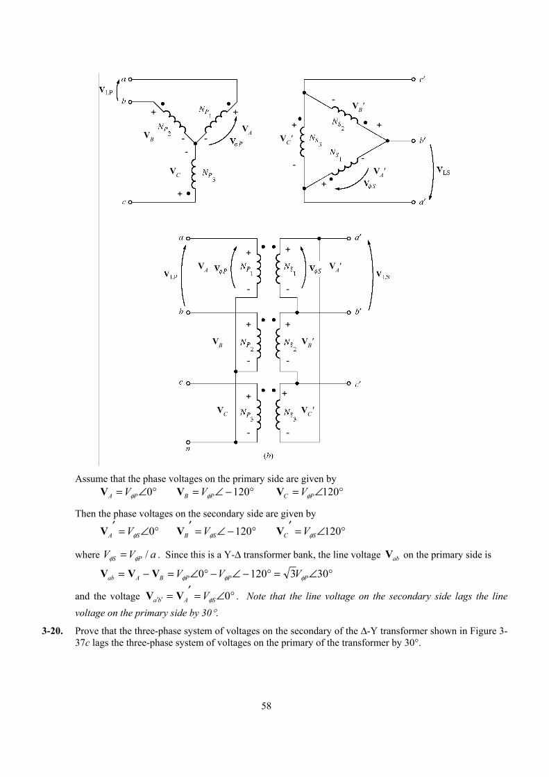
58
VC
VBVA
VC'
VA'
VB'+ +
+
+
+
+- --
-
--
--
--
--
++
++
+ +
VA'
VB'
VC'
VA
VB
VC
Assume that the phase voltages on the primary side are given by °∠= 0PA VφV °−∠= 120PB VφV °∠= 120PC VφV
Then the phase voltages on the secondary side are given by
°∠=′ 0SA VφV °−∠=′ 120SB VφV °∠=′ 120SC VφV
where aVV PS /φφ = . Since this is a Y-∆ transformer bank, the line voltage abV on the primary side is
°∠=°−∠−°∠=−= 3031200 PPPBAab VVV φφφVVV
and the voltage °∠=′=′′ 0SAba VφVV . Note that the line voltage on the secondary side lags the line
voltage on the primary side by 30°.
3-20. Prove that the three-phase system of voltages on the secondary of the ∆-Y transformer shown in Figure 3-37c lags the three-phase system of voltages on the primary of the transformer by 30°.
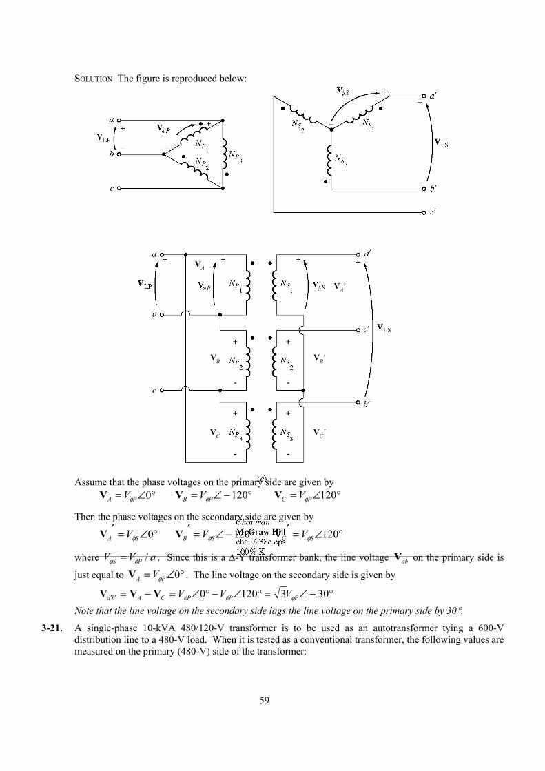
59
SOLUTION The figure is reproduced below:
+ +
++
--
- -
VA
VA'
VB VB'
VC VC'
Assume that the phase voltages on the primary side are given by °∠= 0PA VφV °−∠= 120PB VφV °∠= 120PC VφV
Then the phase voltages on the secondary side are given by
°∠=′ 0SA VφV °−∠=′ 120SB VφV °∠=′ 120SC VφV
where aVV PS /φφ = . Since this is a ∆-Y transformer bank, the line voltage abV on the primary side is
just equal to °∠= 0PA VφV . The line voltage on the secondary side is given by
°−∠=°∠−°∠=−=′′ 3031200 PPPCAba VVV φφφVVV
Note that the line voltage on the secondary side lags the line voltage on the primary side by 30°.
3-21. A single-phase 10-kVA 480/120-V transformer is to be used as an autotransformer tying a 600-V distribution line to a 480-V load. When it is tested as a conventional transformer, the following values are measured on the primary (480-V) side of the transformer:
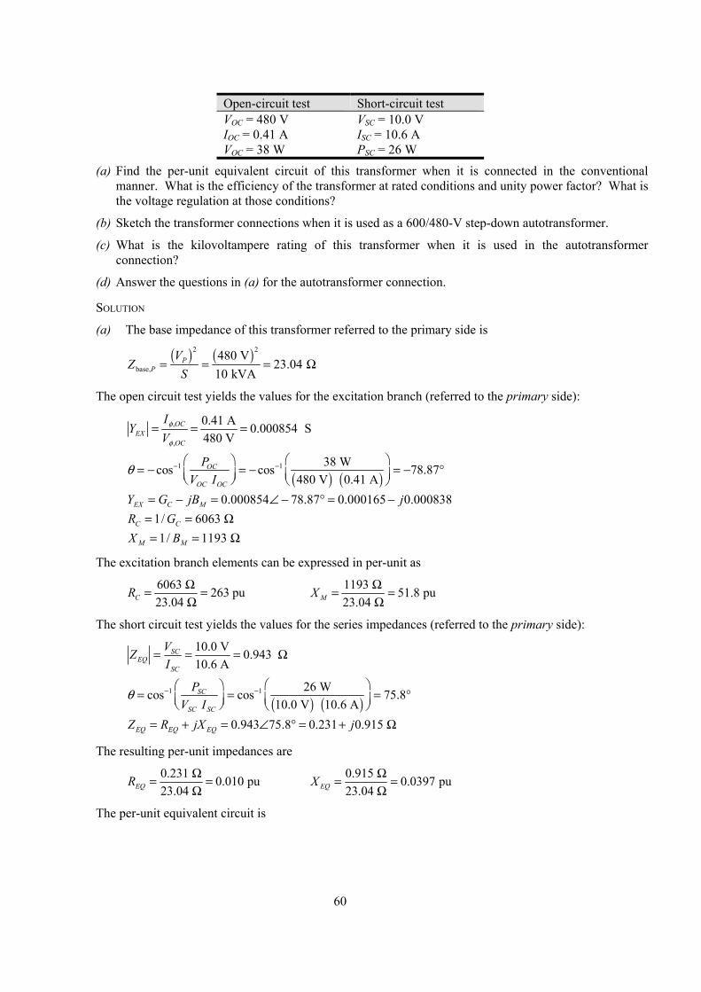
60
Open-circuit test Short-circuit test VOC = 480 V VSC = 10.0 V IOC = 0.41 A ISC = 10.6 A VOC = 38 W PSC = 26 W
(a) Find the per-unit equivalent circuit of this transformer when it is connected in the conventional manner. What is the efficiency of the transformer at rated conditions and unity power factor? What is the voltage regulation at those conditions?
(b) Sketch the transformer connections when it is used as a 600/480-V step-down autotransformer.
(c) What is the kilovoltampere rating of this transformer when it is used in the autotransformer connection?
(d) Answer the questions in (a) for the autotransformer connection.
SOLUTION
(a) The base impedance of this transformer referred to the primary side is
( ) ( )2 2
base,480 V
23.04 10 kVA
PP
VZ
S= = = Ω
The open circuit test yields the values for the excitation branch (referred to the primary side):
,
,
0.41 A 0.000854 S480 V
OCEX
OC
IY
Vφ
φ
= = =
( ) ( )
1 1 38 Wcos cos 78.87 480 V 0.41 A
OC
OC OC
PV I
θ − − = − = − = − °
0.000854 78.87 0.000165 0.000838EX C MY G jB j= − = ∠ − ° = − 1/ 6063 C CR G= = Ω 1/ 1193 M MX B= = Ω
The excitation branch elements can be expressed in per-unit as
6063 263 pu23.04 CR Ω= =
Ω 1193 51.8 pu
23.04 MX Ω= =Ω
The short circuit test yields the values for the series impedances (referred to the primary side):
10.0 V 0.943 10.6 A
SCEQ
SC
VZI
= = = Ω
( ) ( )
1 1 26 Wcos cos 75.8 10.0 V 10.6 ASC
SC SC
PV I
θ − − = = = °
0.943 75.8 0.231 0.915 EQ EQ EQZ R jX j= + = ∠ ° = + Ω
The resulting per-unit impedances are
0.231 0.010 pu23.04 EQR Ω= =
Ω 0.915 0.0397 pu
23.04 EQX Ω= =Ω
The per-unit equivalent circuit is
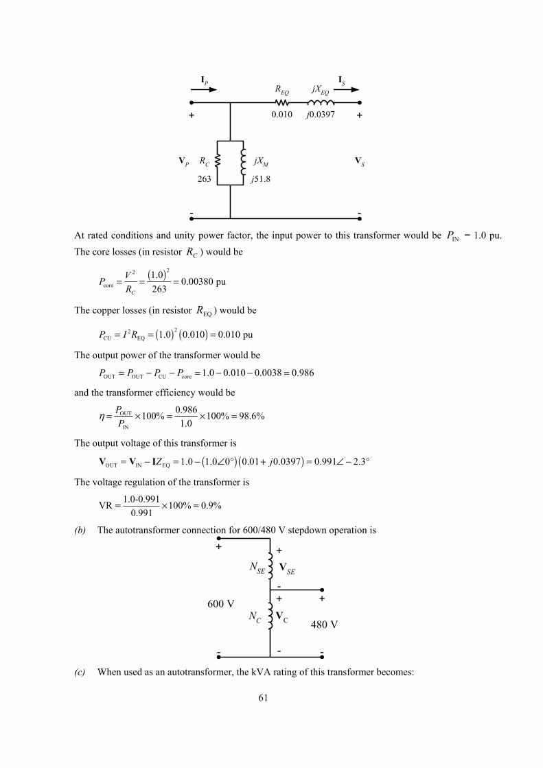
61
+
-
VSVP
IS
+
-
IP
RC jXM
REQ jXEQ
0.010 j0.0397
263 j51.8
At rated conditions and unity power factor, the input power to this transformer would be INP = 1.0 pu.
The core losses (in resistor CR ) would be
( )22
core1.0
0.00380 pu263C
VPR
= = =
The copper losses (in resistor EQR ) would be
( ) ( )22CU EQ 1.0 0.010 0.010 puP I R= = =
The output power of the transformer would be
OUT OUT CU core 1.0 0.010 0.0038 0.986P P P P= − − = − − =
and the transformer efficiency would be
OUT
IN
0.986100% 100% 98.6%1.0
PP
η = × = × =
The output voltage of this transformer is
( ) ( )OUT IN EQ 1.0 1.0 0 0.01 0.0397 0.991 2.3Z j= − = − ∠ ° + = ∠ − °V V I
The voltage regulation of the transformer is
1.0-0.991VR 100% 0.9%0.991
= × =
(b) The autotransformer connection for 600/480 V stepdown operation is
+
-
+
-
480 V
600 VNC
NSE VSE
VC
+
+-
- (c) When used as an autotransformer, the kVA rating of this transformer becomes:
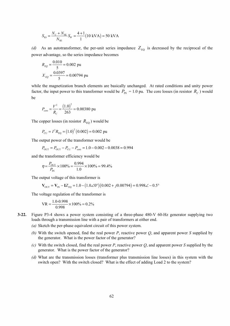
62
( )SEIO
SE
4 1 10 kVA 50 kVA1
CW
N NS SN+ += = =
(d) As an autotransformer, the per-unit series impedance EQZ is decreased by the reciprocal of the power advantage, so the series impedance becomes
0.010 0.002 pu5EQR = =
0.0397 0.00794 pu5EQX = =
while the magnetization branch elements are basically unchanged. At rated conditions and unity power factor, the input power to this transformer would be INP = 1.0 pu. The core losses (in resistor CR ) would be
( )22
core1.0
0.00380 pu263C
VPR
= = =
The copper losses (in resistor EQR ) would be
( ) ( )22CU EQ 1.0 0.002 0.002 puP I R= = =
The output power of the transformer would be
OUT OUT CU core 1.0 0.002 0.0038 0.994P P P P= − − = − − =
and the transformer efficiency would be
OUT
IN
0.994100% 100% 99.4%1.0
PP
η = × = × =
The output voltage of this transformer is
( ) ( )OUT IN EQ 1.0 1.0 0 0.002 0.00794 0.998 0.5Z j= − = − ∠ ° + = ∠ − °V V I
The voltage regulation of the transformer is
1.0-0.998VR 100% 0.2%0.998
= × =
3-22. Figure P3-4 shows a power system consisting of a three-phase 480-V 60-Hz generator supplying two loads through a transmission line with a pair of transformers at either end. (a) Sketch the per-phase equivalent circuit of this power system.
(b) With the switch opened, find the real power P, reactive power Q, and apparent power S supplied by the generator. What is the power factor of the generator?
(c) With the switch closed, find the real power P, reactive power Q, and apparent power S supplied by the generator. What is the power factor of the generator?
(d) What are the transmission losses (transformer plus transmission line losses) in this system with the switch open? With the switch closed? What is the effect of adding Load 2 to the system?
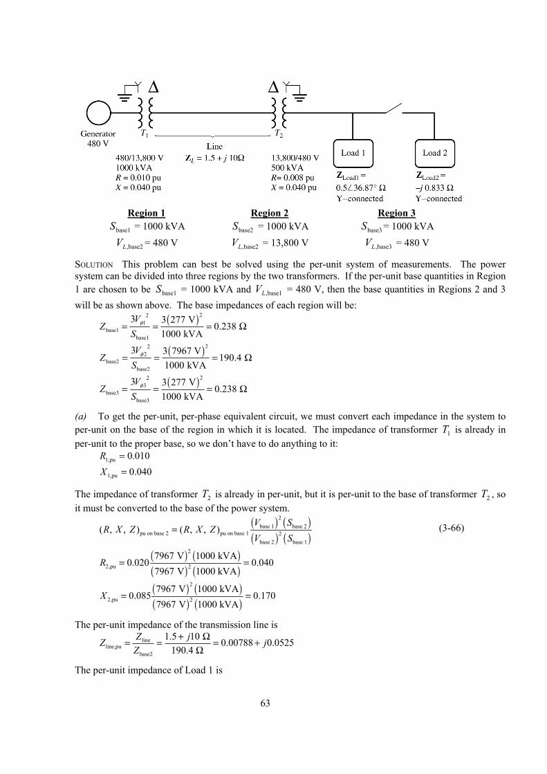
63
Region 1 Region 2 Region 3
base1S = 1000 kVA base2S = 1000 kVA base3S = 1000 kVA
base2,LV = 480 V base2,LV = 13,800 V base3,LV = 480 V
SOLUTION This problem can best be solved using the per-unit system of measurements. The power system can be divided into three regions by the two transformers. If the per-unit base quantities in Region 1 are chosen to be base1S = 1000 kVA and base1,LV = 480 V, then the base quantities in Regions 2 and 3 will be as shown above. The base impedances of each region will be:
( )221
base1base1
3 3 277 V0.238
1000 kVAV
ZS
φ= = = Ω
( )222
base2base2
3 3 7967 V190.4
1000 kVAV
ZS
φ= = = Ω
( )223
base3base3
3 3 277 V0.238
1000 kVAV
ZS
φ= = = Ω
(a) To get the per-unit, per-phase equivalent circuit, we must convert each impedance in the system to per-unit on the base of the region in which it is located. The impedance of transformer 1T is already in per-unit to the proper base, so we don’t have to do anything to it:
010.0pu,1 =R 040.0pu,1 =X
The impedance of transformer 2T is already in per-unit, but it is per-unit to the base of transformer 2T , so it must be converted to the base of the power system.
( ) ( )( ) ( )
2base 1 base 2
pu on base 2 pu on base 1 2base 2 base 1
( , , ) ( , , )V S
R X Z R X ZV S
= (3-66)
( ) ( )( ) ( )
2
2,pu 2
7967 V 1000 kVA0.020 0.040
7967 V 1000 kVAR = =
( ) ( )( ) ( )
2
2,pu 2
7967 V 1000 kVA0.085 0.170
7967 V 1000 kVAX = =
The per-unit impedance of the transmission line is
lineline,pu
base2
1.5 10 0.00788 0.0525190.4
Z jZ jZ
+ Ω= = = +Ω
The per-unit impedance of Load 1 is
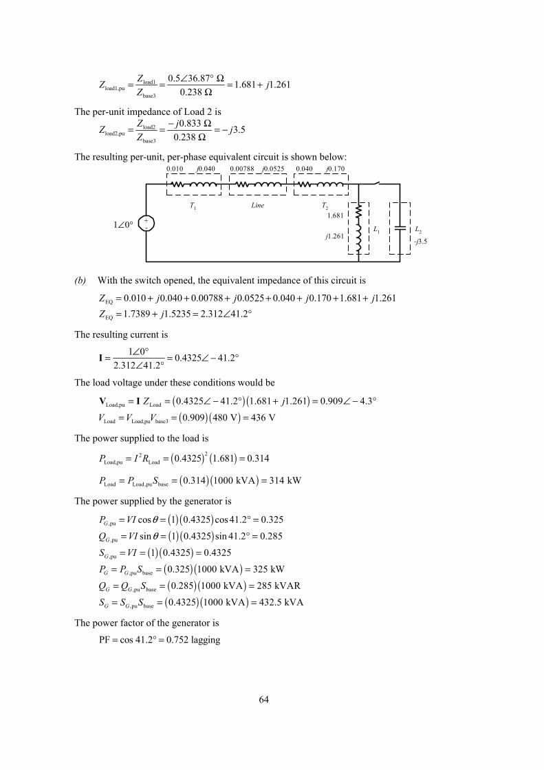
64
load1load1,pu
base3
0.5 36.87 1.681 1.2610.238
ZZ jZ
∠ ° Ω= = = +Ω
The per-unit impedance of Load 2 is
load2load2,pu
base3
0.833 3.50.238
Z jZ jZ
− Ω= = = −Ω
The resulting per-unit, per-phase equivalent circuit is shown below:
+-1∠0°
T1 T2Line
L1 L2
0.010 j0.040 0.00788 j0.0525 0.040 j0.170
1.681
j1.261-j3.5
(b) With the switch opened, the equivalent impedance of this circuit is
EQ 0.010 0.040 0.00788 0.0525 0.040 0.170 1.681 1.261Z j j j j= + + + + + + + EQ 1.7389 1.5235 2.312 41.2Z j= + = ∠ °
The resulting current is
1 0 0.4325 41.22.312 41.2
∠ °= = ∠ − °∠ °
I
The load voltage under these conditions would be
( ) ( )Load,pu Load 0.4325 41.2 1.681 1.261 0.909 4.3Z j= = ∠ − ° + = ∠ − °V I
( ) ( )Load Load,pu base3 0.909 480 V 436 VV V V= = =
The power supplied to the load is
( ) ( )22Load,pu Load 0.4325 1.681 0.314P I R= = =
( ) ( )Load Load,pu base 0.314 1000 kVA 314 kWP P S= = =
The power supplied by the generator is
( ) ( ),pu cos 1 0.4325 cos 41.2 0.325GP VI θ= = ° =
( ) ( ),pu sin 1 0.4325 sin 41.2 0.285GQ VI θ= = ° =
( ) ( ),pu 1 0.4325 0.4325GS VI= = =
( ) ( ),pu base 0.325 1000 kVA 325 kWG GP P S= = =
( ) ( ),pu base 0.285 1000 kVA 285 kVARG GQ Q S= = =
( ) ( ),pu base 0.4325 1000 kVA 432.5 kVAG GS S S= = =
The power factor of the generator is PF cos 41.2 0.752 lagging= ° =
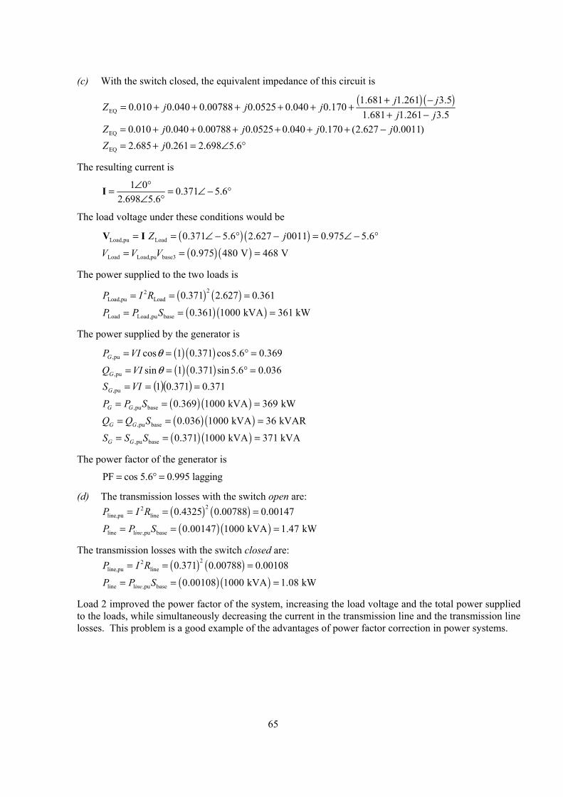
65
(c) With the switch closed, the equivalent impedance of this circuit is
( ) ( )EQ
1.681 1.261 3.50.010 0.040 0.00788 0.0525 0.040 0.170
1.681 1.261 3.5j j
Z j j jj j
+ −= + + + + + +
+ −
EQ 0.010 0.040 0.00788 0.0525 0.040 0.170 (2.627 0.0011)Z j j j j= + + + + + + − EQ 2.685 0.261 2.698 5.6Z j= + = ∠ °
The resulting current is
1 0 0.371 5.62.698 5.6
∠ °= = ∠ − °∠ °
I
The load voltage under these conditions would be
( ) ( )Load,pu Load 0.371 5.6 2.627 0011 0.975 5.6Z j= = ∠ − ° − = ∠ − °V I
( ) ( )Load Load,pu base3 0.975 480 V 468 VV V V= = =
The power supplied to the two loads is
( ) ( )22Load,pu Load 0.371 2.627 0.361P I R= = =
( ) ( )Load Load,pu base 0.361 1000 kVA 361 kWP P S= = =
The power supplied by the generator is
( ) ( ),pu cos 1 0.371 cos5.6 0.369GP VI θ= = ° =
( ) ( ),pu sin 1 0.371 sin 5.6 0.036GQ VI θ= = ° = ( )( ) 371.0371.01pu, === VISG
( ) ( ),pu base 0.369 1000 kVA 369 kWG GP P S= = =
( ) ( ),pu base 0.036 1000 kVA 36 kVARG GQ Q S= = =
( ) ( ),pu base 0.371 1000 kVA 371 kVAG GS S S= = =
The power factor of the generator is PF cos 5.6 0.995 lagging= ° =
(d) The transmission losses with the switch open are: ( ) ( )22
line,pu line 0.4325 0.00788 0.00147P I R= = =
( ) ( )line l ,pu base 0.00147 1000 kVA 1.47 kWineP P S= = =
The transmission losses with the switch closed are: ( ) ( )22
line,pu line 0.371 0.00788 0.00108P I R= = =
( ) ( )line l ,pu base 0.00108 1000 kVA 1.08 kWineP P S= = =
Load 2 improved the power factor of the system, increasing the load voltage and the total power supplied to the loads, while simultaneously decreasing the current in the transmission line and the transmission line losses. This problem is a good example of the advantages of power factor correction in power systems.
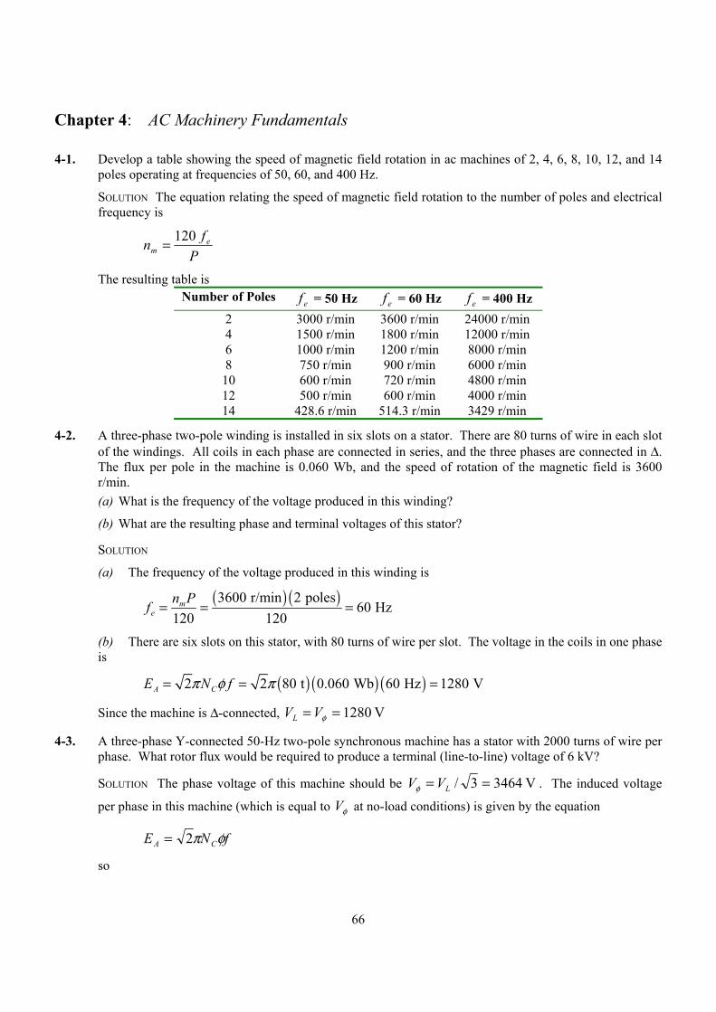
66
Chapter 4: AC Machinery Fundamentals
4-1. Develop a table showing the speed of magnetic field rotation in ac machines of 2, 4, 6, 8, 10, 12, and 14 poles operating at frequencies of 50, 60, and 400 Hz.
SOLUTION The equation relating the speed of magnetic field rotation to the number of poles and electrical frequency is
P
fn em
120=
The resulting table is Number of Poles ef = 50 Hz ef = 60 Hz ef = 400 Hz
2 3000 r/min 3600 r/min 24000 r/min 4 1500 r/min 1800 r/min 12000 r/min 6 1000 r/min 1200 r/min 8000 r/min 8 750 r/min 900 r/min 6000 r/min
10 600 r/min 720 r/min 4800 r/min 12 500 r/min 600 r/min 4000 r/min 14 428.6 r/min 514.3 r/min 3429 r/min
4-2. A three-phase two-pole winding is installed in six slots on a stator. There are 80 turns of wire in each slot of the windings. All coils in each phase are connected in series, and the three phases are connected in ∆. The flux per pole in the machine is 0.060 Wb, and the speed of rotation of the magnetic field is 3600 r/min. (a) What is the frequency of the voltage produced in this winding?
(b) What are the resulting phase and terminal voltages of this stator?
SOLUTION
(a) The frequency of the voltage produced in this winding is
( ) ( )3600 r/min 2 poles
60 Hz120 120
me
n Pf = = =
(b) There are six slots on this stator, with 80 turns of wire per slot. The voltage in the coils in one phase is
( ) ( ) ( )2 2 80 t 0.060 Wb 60 Hz 1280 VA CE N fπ φ π= = =
Since the machine is ∆-connected, V 1280== φVVL
4-3. A three-phase Y-connected 50-Hz two-pole synchronous machine has a stator with 2000 turns of wire per phase. What rotor flux would be required to produce a terminal (line-to-line) voltage of 6 kV?
SOLUTION The phase voltage of this machine should be V 34643/ == LVVφ . The induced voltage
per phase in this machine (which is equal to φV at no-load conditions) is given by the equation
fNE CA φπ2=
so

67
( )( ) Wb 0078.0 Hz50 t20002
V 34642
===ππ
φfN
E
C
A
4-4. Modify the MATLAB in Example 4-1 by swapping the currents flowing in any two phases. What happens to the resulting net magnetic field?
SOLUTION This modification is very simple—just swap the currents supplied to two of the three phases.
% M-file: mag_field2.m% M-file to calculate the net magetic field produced% by a three-phase stator.
% Set up the basic conditionsbmax = 1; % Normalize bmax to 1freq = 60; % 60 Hzw = 2*pi*freq; % angluar velocity (rad/s)
% First, generate the three component magnetic fieldst = 0:1/6000:1/60;Baa = sin(w*t) .* (cos(0) + j*sin(0));Bbb = sin(w*t+2*pi/3) .* (cos(2*pi/3) + j*sin(2*pi/3));Bcc = sin(w*t-2*pi/3) .* (cos(-2*pi/3) + j*sin(-2*pi/3));
% Calculate BnetBnet = Baa + Bbb + Bcc;
% Calculate a circle representing the expected maximum% value of Bnetcircle = 1.5 * (cos(w*t) + j*sin(w*t));
% Plot the magnitude and direction of the resulting magnetic% fields. Note that Baa is black, Bbb is blue, Bcc is% magneta, and Bnet is red.for ii = 1:length(t)
% Plot the reference circleplot(circle,'k');hold on;
% Plot the four magnetic fieldsplot([0 real(Baa(ii))],[0 imag(Baa(ii))],'k','LineWidth',2);plot([0 real(Bbb(ii))],[0 imag(Bbb(ii))],'b','LineWidth',2);plot([0 real(Bcc(ii))],[0 imag(Bcc(ii))],'m','LineWidth',2);plot([0 real(Bnet(ii))],[0 imag(Bnet(ii))],'r','LineWidth',3);axis square;axis([-2 2 -2 2]);drawnow;hold off;
end
When this program executes, the net magnetic field rotates clockwise, instead of counterclockwise.
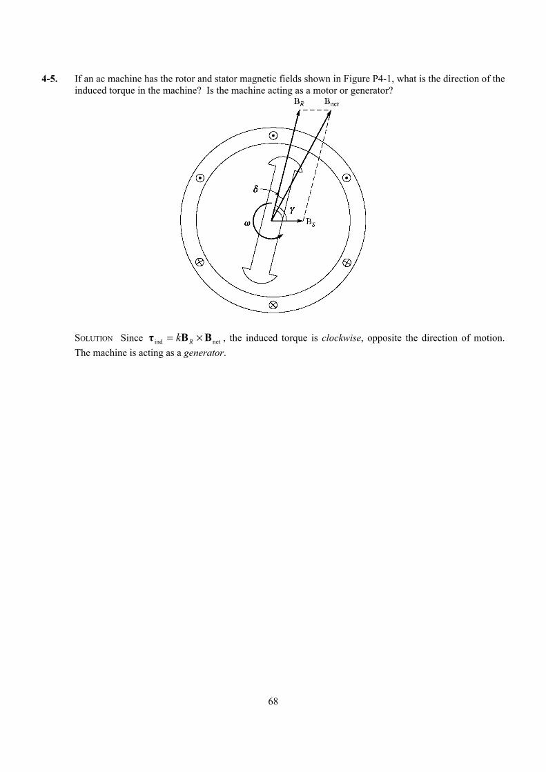
68
4-5. If an ac machine has the rotor and stator magnetic fields shown in Figure P4-1, what is the direction of the induced torque in the machine? Is the machine acting as a motor or generator?
SOLUTION Since netind BBτ ×= Rk , the induced torque is clockwise, opposite the direction of motion.
The machine is acting as a generator.
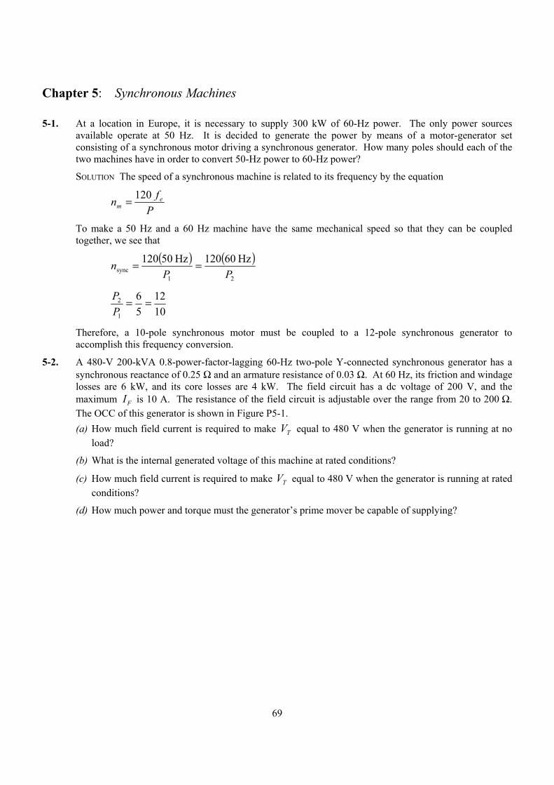
69
Chapter 5: Synchronous Machines
5-1. At a location in Europe, it is necessary to supply 300 kW of 60-Hz power. The only power sources available operate at 50 Hz. It is decided to generate the power by means of a motor-generator set consisting of a synchronous motor driving a synchronous generator. How many poles should each of the two machines have in order to convert 50-Hz power to 60-Hz power?
SOLUTION The speed of a synchronous machine is related to its frequency by the equation
P
fn em
120=
To make a 50 Hz and a 60 Hz machine have the same mechanical speed so that they can be coupled together, we see that
( ) ( )
21sync
Hz60120 Hz50120PP
n ==
1012
56
1
2 ==PP
Therefore, a 10-pole synchronous motor must be coupled to a 12-pole synchronous generator to accomplish this frequency conversion.
5-2. A 480-V 200-kVA 0.8-power-factor-lagging 60-Hz two-pole Y-connected synchronous generator has a synchronous reactance of 0.25 Ω and an armature resistance of 0.03 Ω. At 60 Hz, its friction and windage losses are 6 kW, and its core losses are 4 kW. The field circuit has a dc voltage of 200 V, and the maximum IF is 10 A. The resistance of the field circuit is adjustable over the range from 20 to 200 Ω. The OCC of this generator is shown in Figure P5-1. (a) How much field current is required to make VT equal to 480 V when the generator is running at no
load?
(b) What is the internal generated voltage of this machine at rated conditions?
(c) How much field current is required to make VT equal to 480 V when the generator is running at rated conditions?
(d) How much power and torque must the generator’s prime mover be capable of supplying?
70
SOLUTION
(a) If the no-load terminal voltage is 480 V, the required field current can be read directly from the open-circuit characteristic. It is 4.55 A.
(b) This generator is Y-connected, so AL II = . At rated conditions, the line and phase current in this generator is
( ) A 6.240V 4803
kVA 200 3
====L
LA VPII at an angle of –36.87°
The internal generated voltage of the machine is
ASAAA jXR IIVE ++= φ
( ) ( ) ( ) ( )277 0 0.03 240.6 36.87 A 0.25 240.6 36.87 AA j= ∠ ° + Ω ∠ − ° + Ω ∠ − °E V 8.7322 °∠=AE
(c) The equivalent open-circuit terminal voltage corresponding to an AE of 322 volts is
( ) V 558V 3223oc, ==TV
From the OCC, the required field current is 7.0 A.
(d) The input power to this generator is equal to the output power plus losses. The rated output power is
( ) ( )OUT 200 kVA 0.8 160 kWP = =
( ) ( ) kW 2.5 03.0A 6.24033 22CU =Ω== AA RIP
71
kW 6W&F =P
kW 4core =P
0) assumed(stray =P
kW 2.175straycoreW&FCUOUTIN =++++= PPPPPP
Therefore the prime mover must be capable of supplying 175 kW. Since the generator is a two-pole 60 Hz machine, to must be turning at 3600 r/min. The required torque is
( )
mN 465
r 1rad 2
s 60min 1r/min 3600
kW 2.175INAPP ⋅=
==πω
τm
P
5-3. Assume that the field current of the generator in Problem 5-2 is adjusted to achieve rated voltage (480 V) at full load conditions in each of the questions below. (a) What is the efficiency of the generator at rated load?
(b) What is the voltage regulation of the generator if it is loaded to rated kilovoltamperes with 0.8-PF-lagging loads?
(c) What is the voltage regulation of the generator if it is loaded to rated kilovoltamperes with 0.8-PF-leading loads?
(d) What is the voltage regulation of the generator if it is loaded to rated kilovoltamperes with unity-power-factor loads?
(e) Use MATLAB to plot the terminal voltage of the generator as a function of load for all three power factors.
SOLUTION
(a) This generator is Y-connected, so AL II = . At rated conditions, the line and phase current in this generator is
( ) A 6.240V 4803
kVA 200 3
====L
LA VPII at an angle of –36.87°
The internal generated voltage of the machine at rated conditions is
ASAAA jXR IIVE ++= φ
( ) ( ) ( ) ( )277 0 0.03 240.6 36.87 A 0.25 240.6 36.87 AA j= ∠ ° + Ω ∠ − ° + Ω ∠ − °E V 8.7322 °∠=AE
The input power to this generator is equal to the output power plus losses. The rated output power is
( ) ( )OUT 200 kVA 0.8 160 kWP = =
( ) ( ) kW 2.5 03.0A 6.24033 22CU =Ω== AA RIP
kW 6W&F =P
kW 4core =P
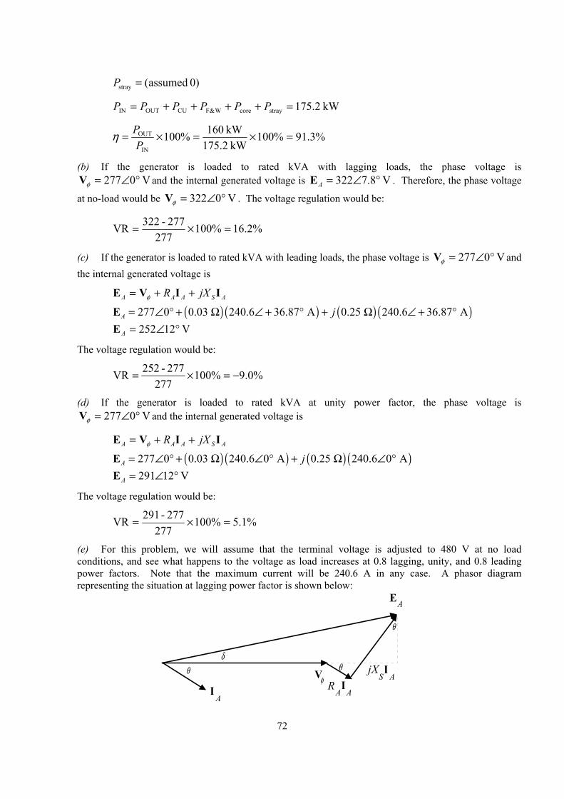
72
0) assumed(stray =P
kW 2.175straycoreW&FCUOUTIN =++++= PPPPPP
%3.91%100kW 175.2
kW 160%100IN
OUT =×=×=P
Pη
(b) If the generator is loaded to rated kVA with lagging loads, the phase voltage is V 0277 °∠=φV and the internal generated voltage is V 8.7322 °∠=AE . Therefore, the phase voltage
at no-load would be V 0322 °∠=φV . The voltage regulation would be:
%2.16%100277
277-322VR =×=
(c) If the generator is loaded to rated kVA with leading loads, the phase voltage is V 0277 °∠=φV and the internal generated voltage is
ASAAA jXR IIVE ++= φ
( ) ( ) ( ) ( )277 0 0.03 240.6 36.87 A 0.25 240.6 36.87 AA j= ∠ ° + Ω ∠ + ° + Ω ∠ + °E V 12252 °∠=AE
The voltage regulation would be:
%0.9%100277
277-252VR −=×=
(d) If the generator is loaded to rated kVA at unity power factor, the phase voltage is V 0277 °∠=φV and the internal generated voltage is
ASAAA jXR IIVE ++= φ
( ) ( ) ( ) ( )277 0 0.03 240.6 0 A 0.25 240.6 0 AA j= ∠ ° + Ω ∠ ° + Ω ∠ °E V 12291 °∠=AE
The voltage regulation would be:
%1.5%100277
277-291VR =×=
(e) For this problem, we will assume that the terminal voltage is adjusted to 480 V at no load conditions, and see what happens to the voltage as load increases at 0.8 lagging, unity, and 0.8 leading power factors. Note that the maximum current will be 240.6 A in any case. A phasor diagram representing the situation at lagging power factor is shown below:
I A
V φ
EA
θδ
θ
θ
I A
R A
jX SI
A
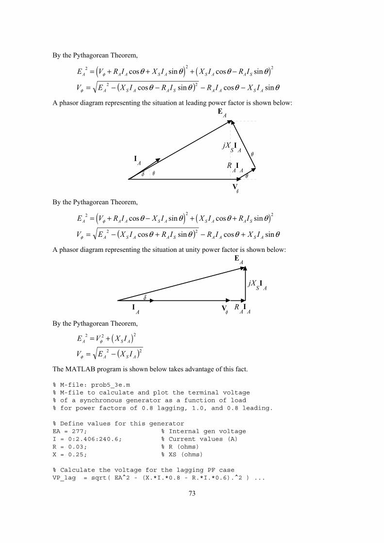
73
By the Pythagorean Theorem,
( ) ( )2 22 cos sin cos sinA A A S A S A A SE V R I X I X I R Iφ θ θ θ θ= + + + −
( ) θθθθφ sincossincos 22ASAASAASA IXIRIRIXEV −−−−=
A phasor diagram representing the situation at leading power factor is shown below:
I A
V φ
EA
θδ θ
θ
I A
R A
jX SI
A
By the Pythagorean Theorem,
( ) ( )2 22 cos sin cos sinA A A S A S A A SE V R I X I X I R Iφ θ θ θ θ= + − + +
( ) θθθθφ sincossincos 22ASAASAASA IXIRIRIXEV +−+−=
A phasor diagram representing the situation at unity power factor is shown below:
I A V φ
EA
δI
AR
A
jX SI
A
By the Pythagorean Theorem,
( )22 2A S AE V X Iφ= +
( )22ASA IXEV −=φ
The MATLAB program is shown below takes advantage of this fact.
% M-file: prob5_3e.m% M-file to calculate and plot the terminal voltage% of a synchronous generator as a function of load% for power factors of 0.8 lagging, 1.0, and 0.8 leading.
% Define values for this generatorEA = 277; % Internal gen voltageI = 0:2.406:240.6; % Current values (A)R = 0.03; % R (ohms)X = 0.25; % XS (ohms)
% Calculate the voltage for the lagging PF caseVP_lag = sqrt( EA^2 - (X.*I.*0.8 - R.*I.*0.6).^2 ) ...
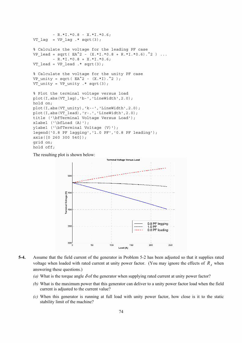
74
- R.*I.*0.8 - X.*I.*0.6;VT_lag = VP_lag .* sqrt(3);
% Calculate the voltage for the leading PF caseVP_lead = sqrt( EA^2 - (X.*I.*0.8 + R.*I.*0.6).^2 ) ...
- R.*I.*0.8 + X.*I.*0.6;VT_lead = VP_lead .* sqrt(3);
% Calculate the voltage for the unity PF caseVP_unity = sqrt( EA^2 - (X.*I).^2 );VT_unity = VP_unity .* sqrt(3);
% Plot the terminal voltage versus loadplot(I,abs(VT_lag),'b-','LineWidth',2.0);hold on;plot(I,abs(VT_unity),'k--','LineWidth',2.0);plot(I,abs(VT_lead),'r-.','LineWidth',2.0);title ('\bfTerminal Voltage Versus Load');xlabel ('\bfLoad (A)');ylabel ('\bfTerminal Voltage (V)');legend('0.8 PF lagging','1.0 PF','0.8 PF leading');axis([0 260 300 540]);grid on;hold off;
The resulting plot is shown below:
5-4. Assume that the field current of the generator in Problem 5-2 has been adjusted so that it supplies rated
voltage when loaded with rated current at unity power factor. (You may ignore the effects of AR when answering these questions.) (a) What is the torque angle δ of the generator when supplying rated current at unity power factor?
(b) What is the maximum power that this generator can deliver to a unity power factor load when the field current is adjusted to the current value?
(c) When this generator is running at full load with unity power factor, how close is it to the static stability limit of the machine?
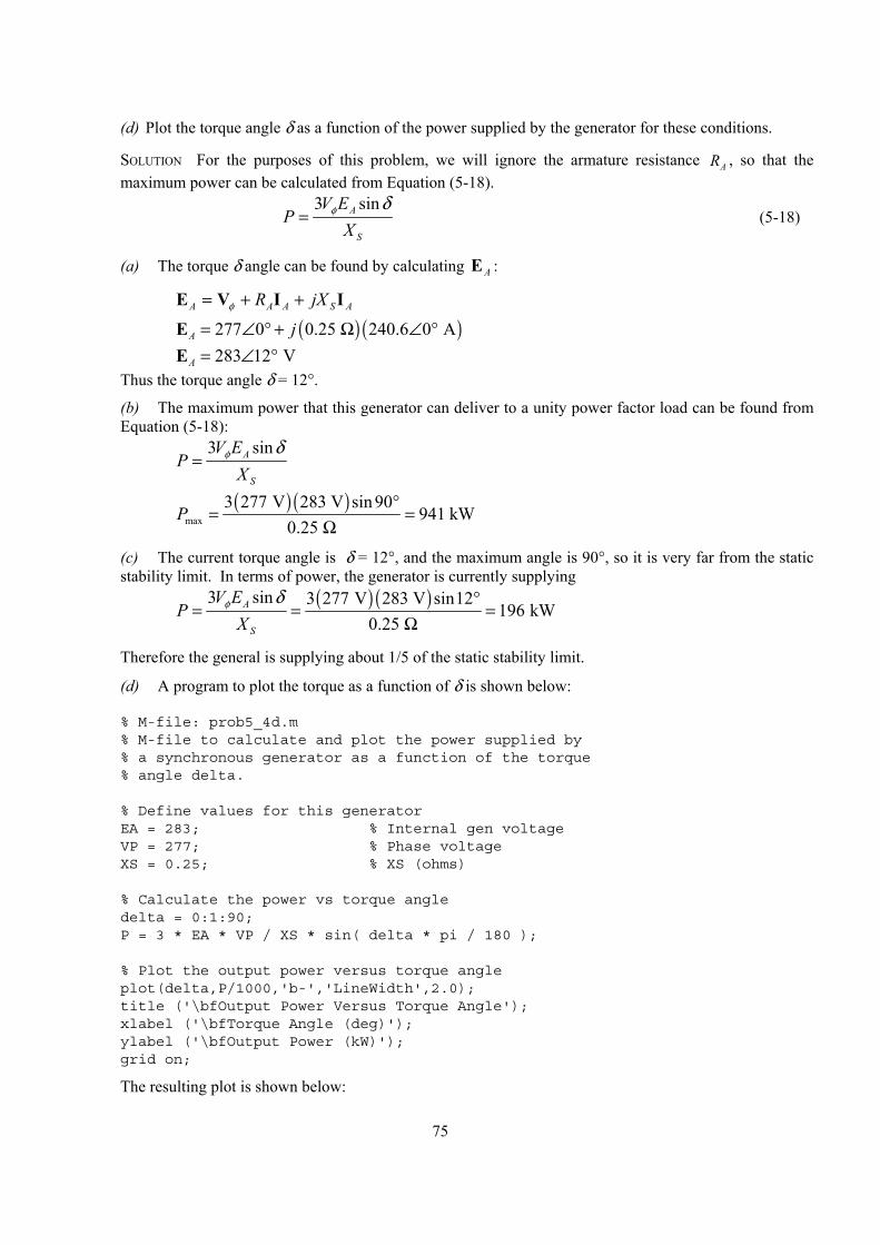
75
(d) Plot the torque angle δ as a function of the power supplied by the generator for these conditions.
SOLUTION For the purposes of this problem, we will ignore the armature resistance AR , so that the maximum power can be calculated from Equation (5-18).
3 sinA
S
V EP
Xφ δ
= (5-18)
(a) The torque δ angle can be found by calculating AE :
ASAAA jXR IIVE ++= φ
( ) ( )277 0 0.25 240.6 0 AA j= ∠ ° + Ω ∠ °E 283 12 VA = ∠ °E Thus the torque angle δ = 12°.
(b) The maximum power that this generator can deliver to a unity power factor load can be found from Equation (5-18):
3 sinA
S
V EP
Xφ δ
=
( ) ( )
max3 277 V 283 V sin 90
941 kW0.25
P°
= =Ω
(c) The current torque angle is δ = 12°, and the maximum angle is 90°, so it is very far from the static stability limit. In terms of power, the generator is currently supplying
( ) ( )3 sin 3 277 V 283 V sin12
196 kW0.25
A
S
V EP
Xφ δ °
= = =Ω
Therefore the general is supplying about 1/5 of the static stability limit.
(d) A program to plot the torque as a function of δ is shown below:
% M-file: prob5_4d.m% M-file to calculate and plot the power supplied by% a synchronous generator as a function of the torque% angle delta.
% Define values for this generatorEA = 283; % Internal gen voltageVP = 277; % Phase voltageXS = 0.25; % XS (ohms)
% Calculate the power vs torque angledelta = 0:1:90;P = 3 * EA * VP / XS * sin( delta * pi / 180 );
% Plot the output power versus torque angleplot(delta,P/1000,'b-','LineWidth',2.0);title ('\bfOutput Power Versus Torque Angle');xlabel ('\bfTorque Angle (deg)');ylabel ('\bfOutput Power (kW)');grid on;
The resulting plot is shown below:
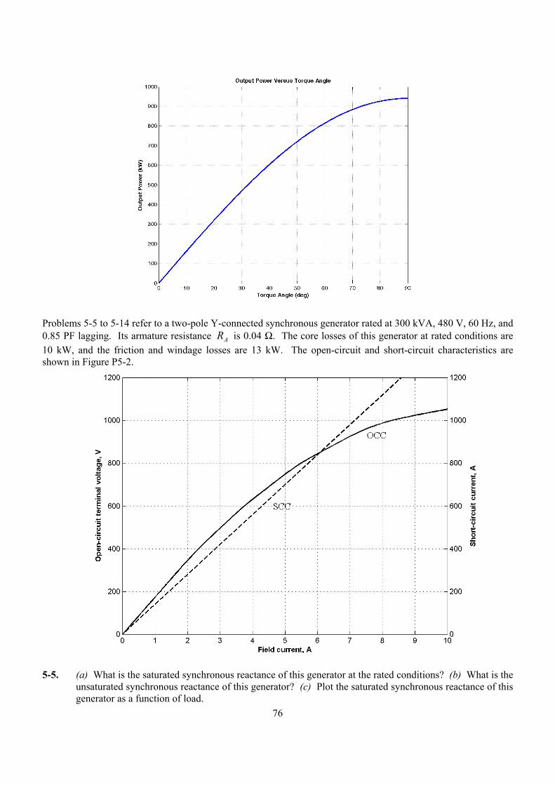
76
Problems 5-5 to 5-14 refer to a two-pole Y-connected synchronous generator rated at 300 kVA, 480 V, 60 Hz, and 0.85 PF lagging. Its armature resistance RA is 0.04 Ω. The core losses of this generator at rated conditions are 10 kW, and the friction and windage losses are 13 kW. The open-circuit and short-circuit characteristics are shown in Figure P5-2.
5-5. (a) What is the saturated synchronous reactance of this generator at the rated conditions? (b) What is the
unsaturated synchronous reactance of this generator? (c) Plot the saturated synchronous reactance of this generator as a function of load.
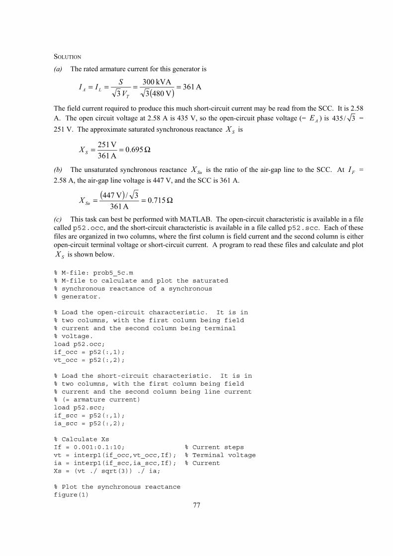
77
SOLUTION
(a) The rated armature current for this generator is
( ) A 361V 8043
kVA 003 3
====T
LA VSII
The field current required to produce this much short-circuit current may be read from the SCC. It is 2.58 A. The open circuit voltage at 2.58 A is 435 V, so the open-circuit phase voltage (= AE ) is 435/ 3 = 251 V. The approximate saturated synchronous reactance SX is
Ω== 695.0A 361V 512
SX
(b) The unsaturated synchronous reactance SuX is the ratio of the air-gap line to the SCC. At FI = 2.58 A, the air-gap line voltage is 447 V, and the SCC is 361 A.
( ) Ω== 715.0
A 3613/V 474
SuX
(c) This task can best be performed with MATLAB. The open-circuit characteristic is available in a file called p52.occ, and the short-circuit characteristic is available in a file called p52.scc. Each of these files are organized in two columns, where the first column is field current and the second column is either open-circuit terminal voltage or short-circuit current. A program to read these files and calculate and plot
SX is shown below.
% M-file: prob5_5c.m% M-file to calculate and plot the saturated% synchronous reactance of a synchronous% generator.
% Load the open-circuit characteristic. It is in% two columns, with the first column being field% current and the second column being terminal% voltage.load p52.occ;if_occ = p52(:,1);vt_occ = p52(:,2);
% Load the short-circuit characteristic. It is in% two columns, with the first column being field% current and the second column being line current% (= armature current)load p52.scc;if_scc = p52(:,1);ia_scc = p52(:,2);
% Calculate XsIf = 0.001:0.1:10; % Current stepsvt = interp1(if_occ,vt_occ,If); % Terminal voltageia = interp1(if_scc,ia_scc,If); % CurrentXs = (vt ./ sqrt(3)) ./ ia;
% Plot the synchronous reactancefigure(1)
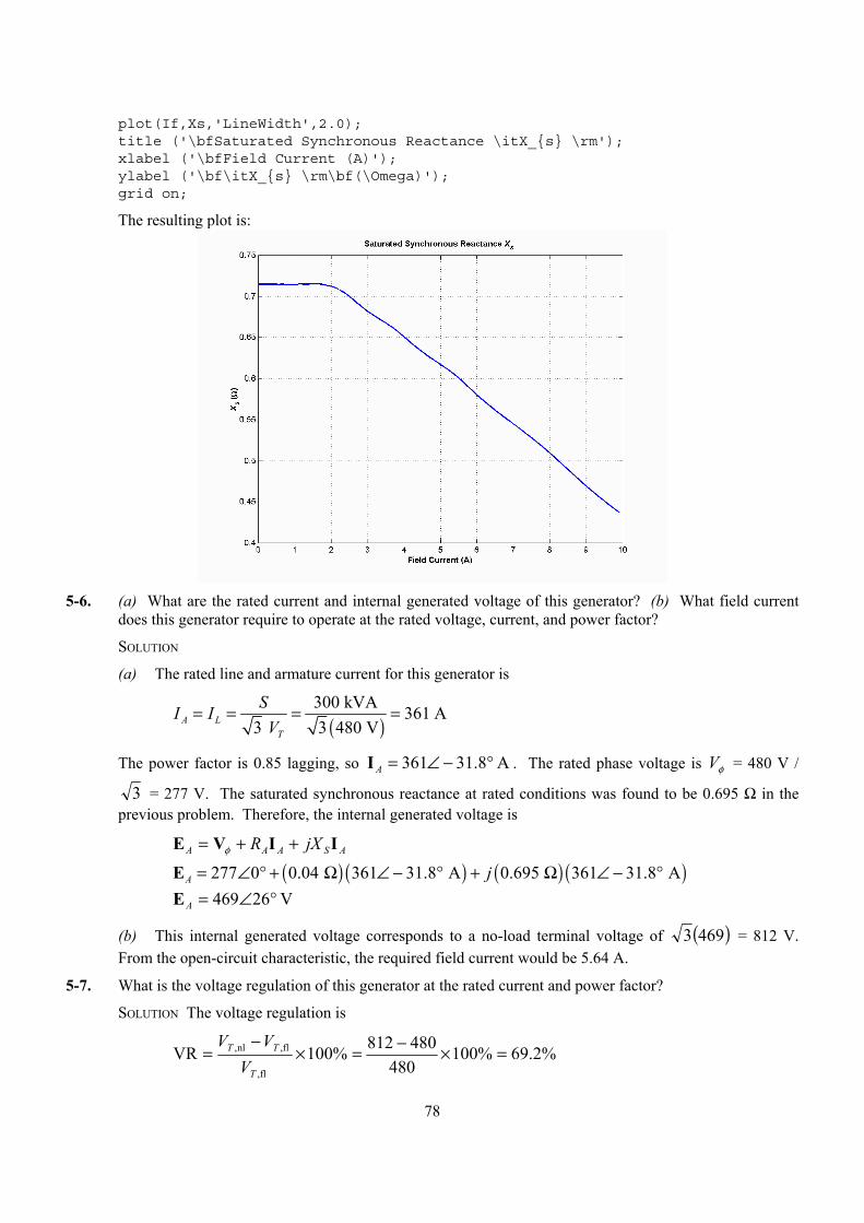
78
plot(If,Xs,'LineWidth',2.0);title ('\bfSaturated Synchronous Reactance \itX_s \rm');xlabel ('\bfField Current (A)');ylabel ('\bf\itX_s \rm\bf(\Omega)');grid on;
The resulting plot is:
5-6. (a) What are the rated current and internal generated voltage of this generator? (b) What field current
does this generator require to operate at the rated voltage, current, and power factor?
SOLUTION
(a) The rated line and armature current for this generator is
( )
300 kVA 361 A3 3 480 VA L
T
SI IV
= = = =
The power factor is 0.85 lagging, so A 8.31361 °−∠=AI . The rated phase voltage is φV = 480 V /
3 = 277 V. The saturated synchronous reactance at rated conditions was found to be 0.695 Ω in the previous problem. Therefore, the internal generated voltage is
ASAAA jXR IIVE ++= φ
( ) ( ) ( ) ( )277 0 0.04 361 31.8 A 0.695 361 31.8 AA j= ∠ ° + Ω ∠ − ° + Ω ∠ − °E V 26469 °∠=AE
(b) This internal generated voltage corresponds to a no-load terminal voltage of ( )4693 = 812 V. From the open-circuit characteristic, the required field current would be 5.64 A.
5-7. What is the voltage regulation of this generator at the rated current and power factor?
SOLUTION The voltage regulation is
%2.69%100480
480812%100VRfl,
fl,nl, =×−=×−
=T
TT
VVV
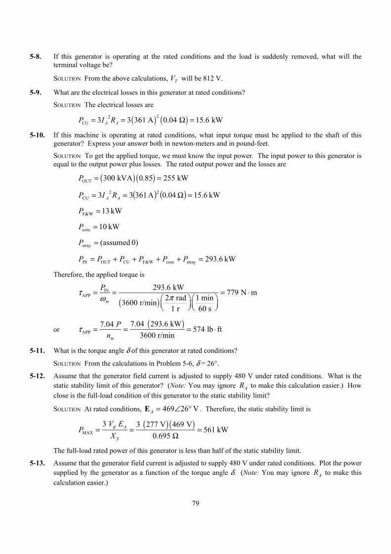
79
5-8. If this generator is operating at the rated conditions and the load is suddenly removed, what will the terminal voltage be?
SOLUTION From the above calculations, TV will be 812 V.
5-9. What are the electrical losses in this generator at rated conditions?
SOLUTION The electrical losses are
( ) ( )22CU 3 3 361 A 0.04 15.6 kWA AP I R= = Ω =
5-10. If this machine is operating at rated conditions, what input torque must be applied to the shaft of this generator? Express your answer both in newton-meters and in pound-feet.
SOLUTION To get the applied torque, we must know the input power. The input power to this generator is equal to the output power plus losses. The rated output power and the losses are
( ) ( )OUT 300 kVA 0.85 255 kWP = =
( ) ( ) kW 6.15 04.0A 36133 22CU =Ω== AA RIP
kW 13W&F =P
kW 10core =P
0) assumed(stray =P
kW 6.293straycoreW&FCUOUTIN =++++= PPPPPP
Therefore, the applied torque is
( )
INAPP
293.6 kW 779 N m2 rad 1 min3600 r/min
1 r 60 sm
Pτ πω= = = ⋅
or ( )
APP7.04 293.6 kW7.04 574 lb ft
3600 r/minm
Pn
τ = = = ⋅
5-11. What is the torque angle δ of this generator at rated conditions?
SOLUTION From the calculations in Problem 5-6, δ = 26°.
5-12. Assume that the generator field current is adjusted to supply 480 V under rated conditions. What is the static stability limit of this generator? (Note: You may ignore AR to make this calculation easier.) How close is the full-load condition of this generator to the static stability limit?
SOLUTION At rated conditions, V 26469 °∠=AE . Therefore, the static stability limit is
( ) ( )
MAX
3 3 277 V 469 V561 kW
0.695 A
S
V EP
Xφ= = =
Ω
The full-load rated power of this generator is less than half of the static stability limit.
5-13. Assume that the generator field current is adjusted to supply 480 V under rated conditions. Plot the power supplied by the generator as a function of the torque angle δ. (Note: You may ignore AR to make this calculation easier.)
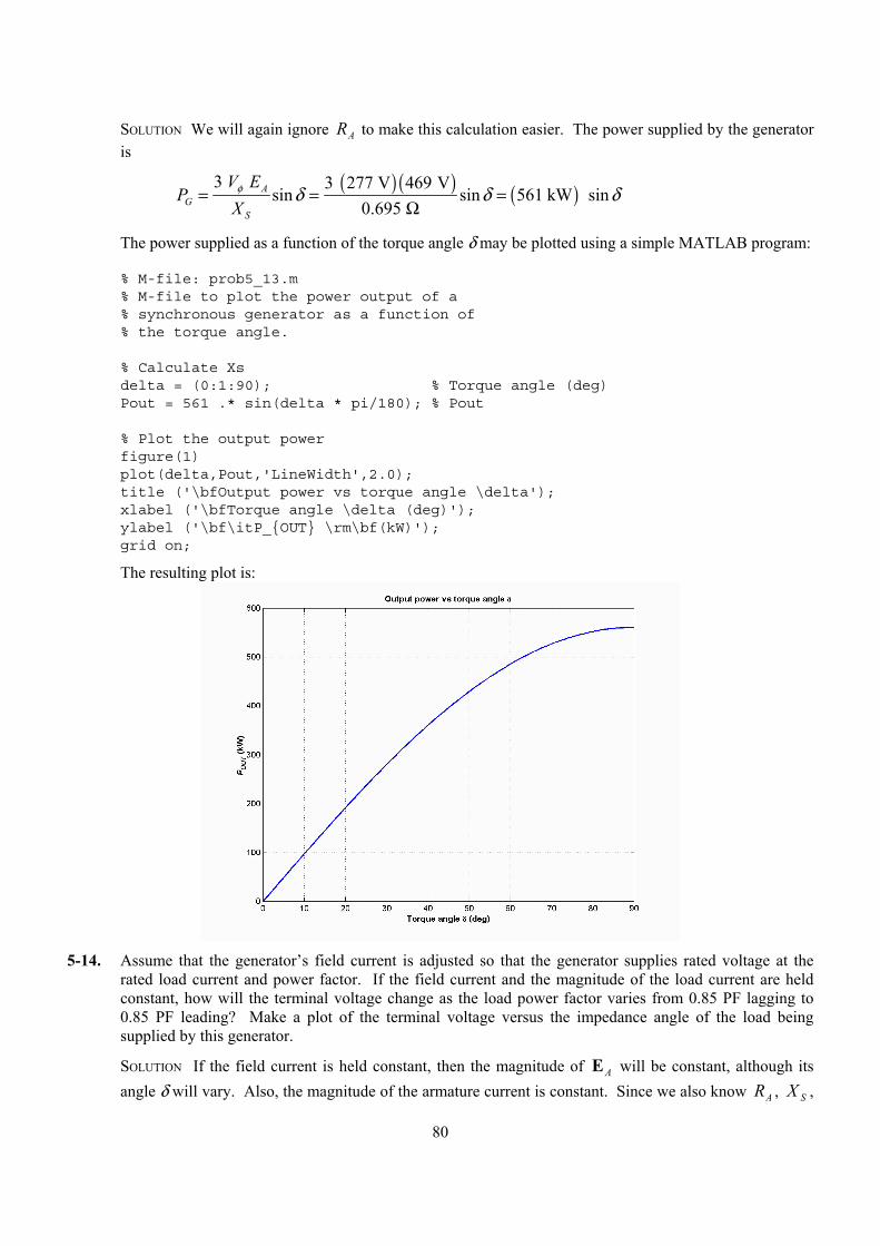
80
SOLUTION We will again ignore AR to make this calculation easier. The power supplied by the generator is
( ) ( ) ( )3 3 277 V 469 V
sin sin 561 kW sin0.695
AG
S
V EP
Xφ δ δ δ= = =
Ω
The power supplied as a function of the torque angle δ may be plotted using a simple MATLAB program:
% M-file: prob5_13.m% M-file to plot the power output of a% synchronous generator as a function of% the torque angle.
% Calculate Xsdelta = (0:1:90); % Torque angle (deg)Pout = 561 .* sin(delta * pi/180); % Pout
% Plot the output powerfigure(1)plot(delta,Pout,'LineWidth',2.0);title ('\bfOutput power vs torque angle \delta');xlabel ('\bfTorque angle \delta (deg)');ylabel ('\bf\itP_OUT \rm\bf(kW)');grid on;
The resulting plot is:
5-14. Assume that the generator’s field current is adjusted so that the generator supplies rated voltage at the
rated load current and power factor. If the field current and the magnitude of the load current are held constant, how will the terminal voltage change as the load power factor varies from 0.85 PF lagging to 0.85 PF leading? Make a plot of the terminal voltage versus the impedance angle of the load being supplied by this generator.
SOLUTION If the field current is held constant, then the magnitude of AE will be constant, although its angle δ will vary. Also, the magnitude of the armature current is constant. Since we also know AR , SX ,
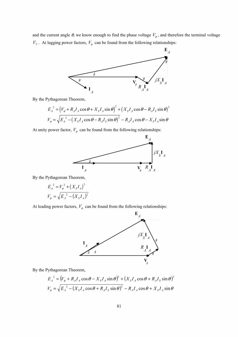
81
and the current angle θ, we know enough to find the phase voltage φV , and therefore the terminal voltage
TV . At lagging power factors, φV can be found from the following relationships:
I A
V φ
EA
θδ
θ
θ
I A
R A
jX SI
A
By the Pythagorean Theorem,
( ) ( )2 22 cos sin cos sinA A A S A S A A SE V R I X I X I R Iφ θ θ θ θ= + + + −
( )22 cos sin cos sinA S A A S A A S AV E X I R I R I X Iφ θ θ θ θ= − − − −
At unity power factor, φV can be found from the following relationships:
I A V φ
EA
δI
AR
A
jX SI
A
By the Pythagorean Theorem,
( )22 2A S AE V X Iφ= +
( )22ASA IXEV −=φ
At leading power factors, φV can be found from the following relationships:
I A
V φ
EA
θδ θ
θ
I A
R A
jX SI
A
By the Pythagorean Theorem,
( ) ( )222 sincossincos θθθθφ SAASASAAA IRIXIXIRVE ++−+=
( ) θθθθφ sincossincos 22ASAASAASA IXIRIRIXEV +−+−=

82
If we examine these three cases, we can see that the only difference among them is the sign of the term θsin . If θ is taken as positive for lagging power factors and negative for leading power factors (in other
words, if θ is the impedance angle), then all three cases can be represented by the single equation:
( )22 cos sin cos sinA S A A S A A S AV E X I R I R I X Iφ θ θ θ θ= − − − −
A MATLAB program that calculates terminal voltage as function of impedance angle is shown below:
% M-file: prob5_14.m% M-file to calculate and plot the terminal voltage% of a synchronous generator as a function of impedance% angle as PF changes from 0.85 lagging to 0.85% leading.
% Define values for this generatorEA = 469; % Internal gen voltageI = 361; % Current (A)R = 0.04; % R (ohms)X = 0.695; % XS (ohms)
% Calculate impedance angle theta in degreestheta = -31.8:0.318:31.8;th = theta * pi/180; % In radians
% Calculate the phase voltage and terminal voltageVP = sqrt( EA^2 - (X.*I.*cos(th) - R.*I.*sin(th)).^2 ) ...
- R.*I.*cos(th) - X.*I.*sin(th);VT = VP .* sqrt(3);
% Plot the terminal voltage versus power factorfigure(1);plot(theta,abs(VT),'b-','LineWidth',2.0);title ('\bfTerminal Voltage Versus Load');xlabel ('\bfImpedance Angle (deg)');ylabel ('\bfTerminal Voltage (V)');%axis([0 260 300 540]);grid on;hold off;
The resulting plot of terminal voltage versus impedance angle (with field and armature currents held constant) is shown below:
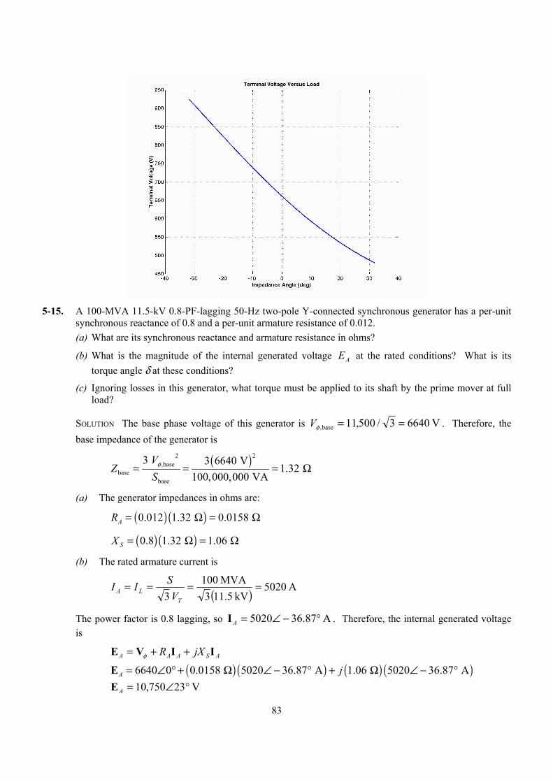
83
5-15. A 100-MVA 11.5-kV 0.8-PF-lagging 50-Hz two-pole Y-connected synchronous generator has a per-unit
synchronous reactance of 0.8 and a per-unit armature resistance of 0.012. (a) What are its synchronous reactance and armature resistance in ohms?
(b) What is the magnitude of the internal generated voltage EA at the rated conditions? What is its torque angle δ at these conditions?
(c) Ignoring losses in this generator, what torque must be applied to its shaft by the prime mover at full load?
SOLUTION The base phase voltage of this generator is V 66403/500,11base, ==φV . Therefore, the base impedance of the generator is
( )22
,basebase
base
3 3 6640 V1.32
100,000,000 VAV
ZS
φ= = = Ω
(a) The generator impedances in ohms are:
( ) ( )0.012 1.32 0.0158 AR = Ω = Ω
( ) ( )0.8 1.32 1.06 SX = Ω = Ω
(b) The rated armature current is
( ) A 5020kV 11.53
MVA100 3
====T
LA VSII
The power factor is 0.8 lagging, so A 87.365020 °−∠=AI . Therefore, the internal generated voltage is
ASAAA jXR IIVE ++= φ
( ) ( ) ( ) ( )6640 0 0.0158 5020 36.87 A 1.06 5020 36.87 AA j= ∠ ° + Ω ∠ − ° + Ω ∠ − °E V 23750,10 °∠=AE
84
Therefore, the magnitude of the internal generated voltage AE = 10,750 V, and the torque angle δ = 23°.
(c) Ignoring losses, the input power would equal the output power. Since
( ) ( )OUT 0.80 100 MVA 80 MWP = =
and
( )
sync120 50 Hz120 3000 r/min
2efn
P= = =
the applied torque would be
( ) ( ) ( )app ind80,000,000 W 255,000 N m
3000 r/min 2 rad/r 1 min/60 sτ τ
π= = = ⋅
5-16. A three-phase Y-connected synchronous generator is rated 120 MVA, 13.8 kV, 0.85 PF lagging, and 60 Hz. Its synchronous reactance is 0.7 Ω, and its resistance may be ignored. (a) What is its voltage regulation?
(b) What would the voltage and apparent power rating of this generator be if it were operated at 50 Hz with the same armature and field losses as it had at 60 Hz?
(c) What would the voltage regulation of the generator be at 50 Hz?
SOLUTION
(a) The rated armature current is
( ) A 5020kV 13.83
MVA120 3
====T
LA VSII
The power factor is 0.85 lagging, so A 8.315020 °−∠=AI . Therefore, the internal generated voltage is
ASAAA jXR IIVE ++= φ
( ) ( )7967 0 0.7 5020 31.8 AA j= ∠ ° + Ω ∠ − °E V 9.16260,10 °∠=AE
The resulting voltage regulation is
%8.28%1007967
7967-10,260VR =×=
(b) If the generator is to be operated at 50 Hz with the same armature and field losses as at 60 Hz (so that the windings do not overheat), then its armature and field currents must not change. Since the voltage of the generator is directly proportional to the speed of the generator, the voltage rating (and hence the apparent power rating) of the generator will be reduced by a factor of 5/6.
( ),rated5 13.8 kV 11.5 kV6TV = =
( )rated5 120 MVA 100 MVA6
S = =
Also, the synchronous reactance will be reduced by a factor of 5/6.
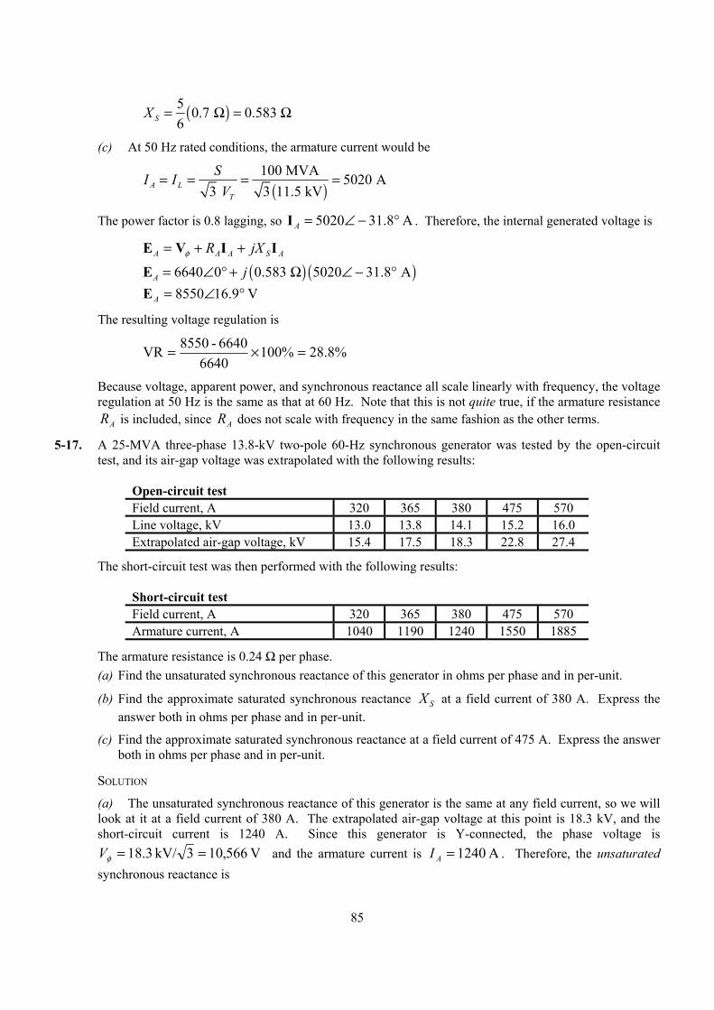
85
( )5 0.7 0.583 6SX = Ω = Ω
(c) At 50 Hz rated conditions, the armature current would be
( )
100 MVA 5020 A3 3 11.5 kVA L
T
SI IV
= = = =
The power factor is 0.8 lagging, so A 8.315020 °−∠=AI . Therefore, the internal generated voltage is
ASAAA jXR IIVE ++= φ
( ) ( )6640 0 0.583 5020 31.8 AA j= ∠ ° + Ω ∠ − °E V 9.168550 °∠=AE
The resulting voltage regulation is
%8.28%1006640
6640-8550VR =×=
Because voltage, apparent power, and synchronous reactance all scale linearly with frequency, the voltage regulation at 50 Hz is the same as that at 60 Hz. Note that this is not quite true, if the armature resistance
AR is included, since AR does not scale with frequency in the same fashion as the other terms.
5-17. A 25-MVA three-phase 13.8-kV two-pole 60-Hz synchronous generator was tested by the open-circuit test, and its air-gap voltage was extrapolated with the following results:
Open-circuit test Field current, A 320 365 380 475 570 Line voltage, kV 13.0 13.8 14.1 15.2 16.0 Extrapolated air-gap voltage, kV 15.4 17.5 18.3 22.8 27.4
The short-circuit test was then performed with the following results:
Short-circuit test Field current, A 320 365 380 475 570 Armature current, A 1040 1190 1240 1550 1885
The armature resistance is 0.24 Ω per phase. (a) Find the unsaturated synchronous reactance of this generator in ohms per phase and in per-unit.
(b) Find the approximate saturated synchronous reactance X S at a field current of 380 A. Express the answer both in ohms per phase and in per-unit.
(c) Find the approximate saturated synchronous reactance at a field current of 475 A. Express the answer both in ohms per phase and in per-unit.
SOLUTION
(a) The unsaturated synchronous reactance of this generator is the same at any field current, so we will look at it at a field current of 380 A. The extrapolated air-gap voltage at this point is 18.3 kV, and the short-circuit current is 1240 A. Since this generator is Y-connected, the phase voltage is
V 566,103kV/ 3.18 ==φV and the armature current is A 1240=AI . Therefore, the unsaturated synchronous reactance is
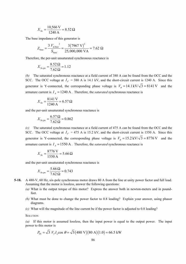
86
Ω== 52.8A 1240V 566,10
SuX
The base impedance of this generator is
( )22
,basebase
base
3 3 7967 V7.62
25,000,000 VAV
ZS
φ= = = Ω
Therefore, the per-unit unsaturated synchronous reactance is
12.1 7.62 52.8
pu, =ΩΩ=SuX
(b) The saturated synchronous reactance at a field current of 380 A can be found from the OCC and the SCC. The OCC voltage at FI = 380 A is 14.1 kV, and the short-circuit current is 1240 A. Since this
generator is Y-connected, the corresponding phase voltage is V 81413kV/ 1.14 ==φV and the
armature current is A 1240=AI . Therefore, the saturated synchronous reactance is
Ω== 57.6A 1240V 1418
SuX
and the per-unit unsaturated synchronous reactance is
862.0 7.62 .576
pu, =ΩΩ=SuX
(c) The saturated synchronous reactance at a field current of 475 A can be found from the OCC and the SCC. The OCC voltage at FI = 475 A is 15.2 kV, and the short-circuit current is 1550 A. Since this
generator is Y-connected, the corresponding phase voltage is V 87763kV/ 2.15 ==φV and the
armature current is A 1550=AI . Therefore, the saturated synchronous reactance is
Ω== 66.5A 1550V 7678
SuX
and the per-unit unsaturated synchronous reactance is
743.0 7.62 .665
pu, =ΩΩ=SuX
5-18. A 480-V, 60 Hz, six-pole synchronous motor draws 80 A from the line at unity power factor and full load. Assuming that the motor is lossless, answer the following questions: (a) What is the output torque of this motor? Express the answer both in newton-meters and in pound-
feet.
(b) What must be done to change the power factor to 0.8 leading? Explain your answer, using phasor diagrams.
(c) What will the magnitude of the line current be if the power factor is adjusted to 0.8 leading?
SOLUTION
(a) If this motor is assumed lossless, then the input power is equal to the output power. The input power to this motor is
( ) ( ) ( )IN 3 cos 3 480 V 80 A 1.0 66.5 kWT LP V I θ= = =
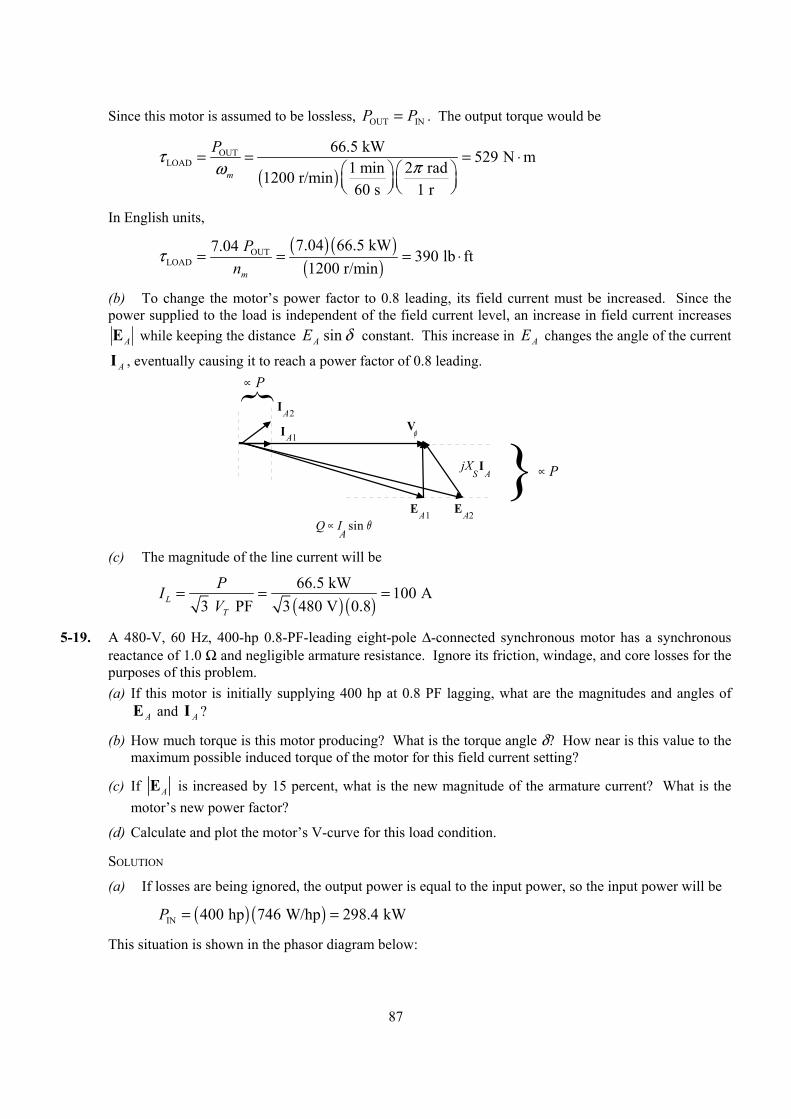
87
Since this motor is assumed to be lossless, OUT INP P= . The output torque would be
( )
OUTLOAD
66.5 kW 529 N m1 min 2 rad1200 r/min60 s 1 r
m
Pτ πω= = = ⋅
In English units,
( ) ( )
( )OUT
LOAD7.04 66.5 kW7.04 390 lb ft
1200 r/minm
Pn
τ = = = ⋅
(b) To change the motor’s power factor to 0.8 leading, its field current must be increased. Since the power supplied to the load is independent of the field current level, an increase in field current increases
AE while keeping the distance δ sin AE constant. This increase in AE changes the angle of the current
AI , eventually causing it to reach a power factor of 0.8 leading.
V φ
EA1
jX S
I A
EA2
IA2
IA1
Q ∝ I sin θA
∝ P
∝ P
(c) The magnitude of the line current will be
( ) ( )66.5 kW 100 A
3 PF 3 480 V 0.8LT
PIV
= = =
5-19. A 480-V, 60 Hz, 400-hp 0.8-PF-leading eight-pole ∆-connected synchronous motor has a synchronous reactance of 1.0 Ω and negligible armature resistance. Ignore its friction, windage, and core losses for the purposes of this problem. (a) If this motor is initially supplying 400 hp at 0.8 PF lagging, what are the magnitudes and angles of
E A and I A ?
(b) How much torque is this motor producing? What is the torque angle δ? How near is this value to the maximum possible induced torque of the motor for this field current setting?
(c) If AE is increased by 15 percent, what is the new magnitude of the armature current? What is the motor’s new power factor?
(d) Calculate and plot the motor’s V-curve for this load condition.
SOLUTION
(a) If losses are being ignored, the output power is equal to the input power, so the input power will be
( ) ( )IN 400 hp 746 W/hp 298.4 kWP = =
This situation is shown in the phasor diagram below:
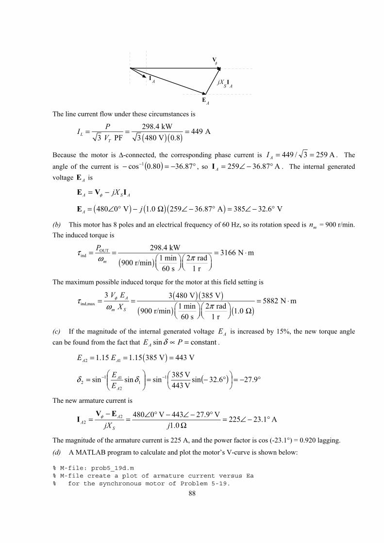
88
V φ
EA
jX S
I A
I A
The line current flow under these circumstances is
( ) ( )298.4 kW 449 A
3 PF 3 480 V 0.8LT
PIV
= = =
Because the motor is ∆-connected, the corresponding phase current is A 2593/449 ==AI . The angle of the current is ( ) °−=− − 87.3680.0cos 1 , so A 87.36259 °−∠=AI . The internal generated voltage AE is
ASA jX IVE −= φ
( ) ( ) ( )480 0 V 1.0 259 36.87 A 385 32.6 VA j= ∠ ° − Ω ∠ − ° = ∠ − °E
(b) This motor has 8 poles and an electrical frequency of 60 Hz, so its rotation speed is mn = 900 r/min. The induced torque is
( )
OUTind
298.4 kW 3166 N m1 min 2 rad900 r/min60 s 1 r
m
Pτ πω= = = ⋅
The maximum possible induced torque for the motor at this field setting is
( ) ( )
( ) ( )ind,max
3 3 480 V 385 V5882 N m
1 min 2 rad 900 r/min 1.0 60 s 1 r
A
m S
V EX
φτ πω= = = ⋅
Ω
(c) If the magnitude of the internal generated voltage AE is increased by 15%, the new torque angle can be found from the fact that constantsin =∝ PEA δ .
( )2 11.15 1.15 385 V 443 VA AE E= = =
( ) °−=
°−=
= −− 9.276.32sin
V 443V 853sinsinsin 1
12
112 δδ
A
A
EE
The new armature current is
A 1.23225 0.1
V 9.27443V 048022 °−∠=
Ω°−∠−°∠=
−=
jjX S
AA
EVI φ
The magnitude of the armature current is 225 A, and the power factor is cos (-23.1°) = 0.920 lagging.
(d) A MATLAB program to calculate and plot the motor’s V-curve is shown below:
% M-file: prob5_19d.m% M-file create a plot of armature current versus Ea% for the synchronous motor of Problem 5-19.
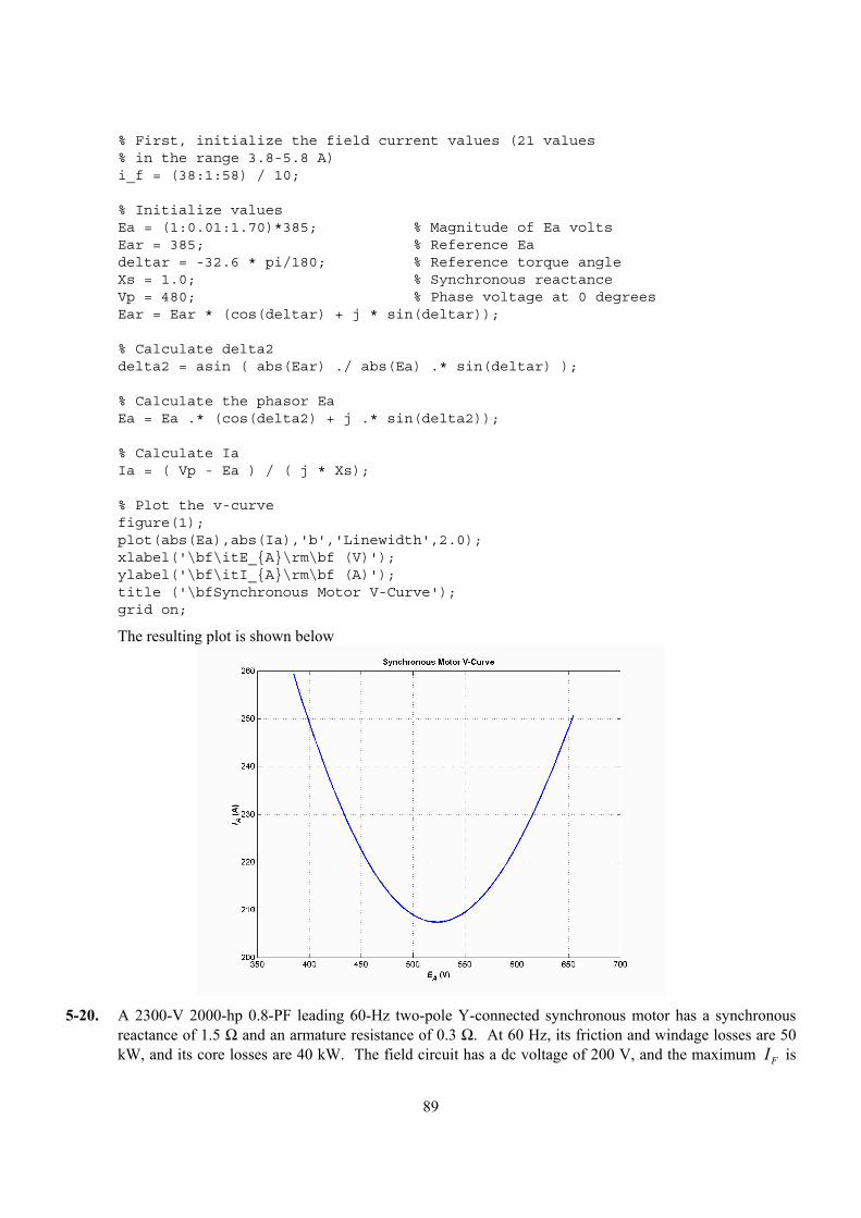
89
% First, initialize the field current values (21 values% in the range 3.8-5.8 A)i_f = (38:1:58) / 10;
% Initialize valuesEa = (1:0.01:1.70)*385; % Magnitude of Ea voltsEar = 385; % Reference Eadeltar = -32.6 * pi/180; % Reference torque angleXs = 1.0; % Synchronous reactanceVp = 480; % Phase voltage at 0 degreesEar = Ear * (cos(deltar) + j * sin(deltar));
% Calculate delta2delta2 = asin ( abs(Ear) ./ abs(Ea) .* sin(deltar) );
% Calculate the phasor EaEa = Ea .* (cos(delta2) + j .* sin(delta2));
% Calculate IaIa = ( Vp - Ea ) / ( j * Xs);
% Plot the v-curvefigure(1);plot(abs(Ea),abs(Ia),'b','Linewidth',2.0);xlabel('\bf\itE_A\rm\bf (V)');ylabel('\bf\itI_A\rm\bf (A)');title ('\bfSynchronous Motor V-Curve');grid on;
The resulting plot is shown below
5-20. A 2300-V 2000-hp 0.8-PF leading 60-Hz two-pole Y-connected synchronous motor has a synchronous
reactance of 1.5 Ω and an armature resistance of 0.3 Ω. At 60 Hz, its friction and windage losses are 50 kW, and its core losses are 40 kW. The field circuit has a dc voltage of 200 V, and the maximum IF is
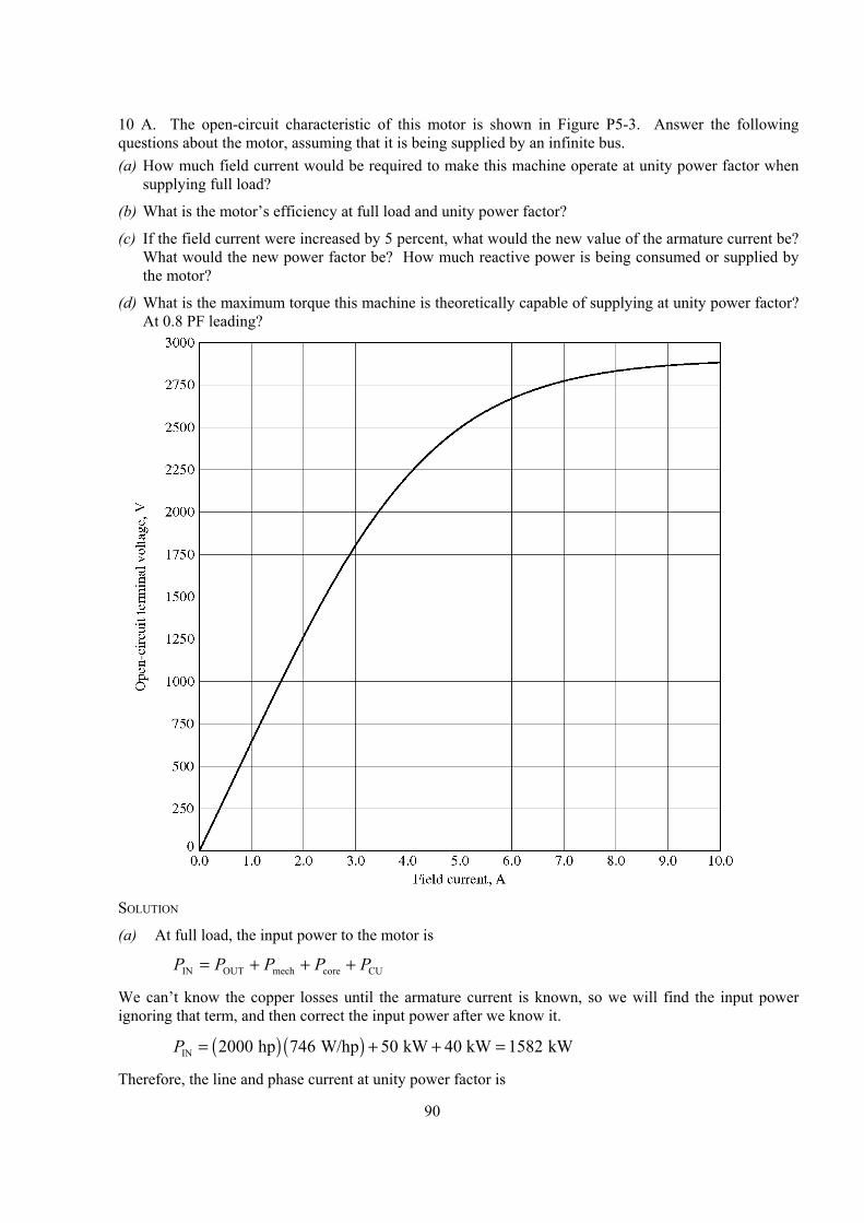
90
10 A. The open-circuit characteristic of this motor is shown in Figure P5-3. Answer the following questions about the motor, assuming that it is being supplied by an infinite bus. (a) How much field current would be required to make this machine operate at unity power factor when
supplying full load?
(b) What is the motor’s efficiency at full load and unity power factor?
(c) If the field current were increased by 5 percent, what would the new value of the armature current be? What would the new power factor be? How much reactive power is being consumed or supplied by the motor?
(d) What is the maximum torque this machine is theoretically capable of supplying at unity power factor? At 0.8 PF leading?
SOLUTION
(a) At full load, the input power to the motor is
CUcoremechOUTIN PPPPP +++=
We can’t know the copper losses until the armature current is known, so we will find the input power ignoring that term, and then correct the input power after we know it.
( ) ( )IN 2000 hp 746 W/hp 50 kW 40 kW 1582 kWP = + + =
Therefore, the line and phase current at unity power factor is
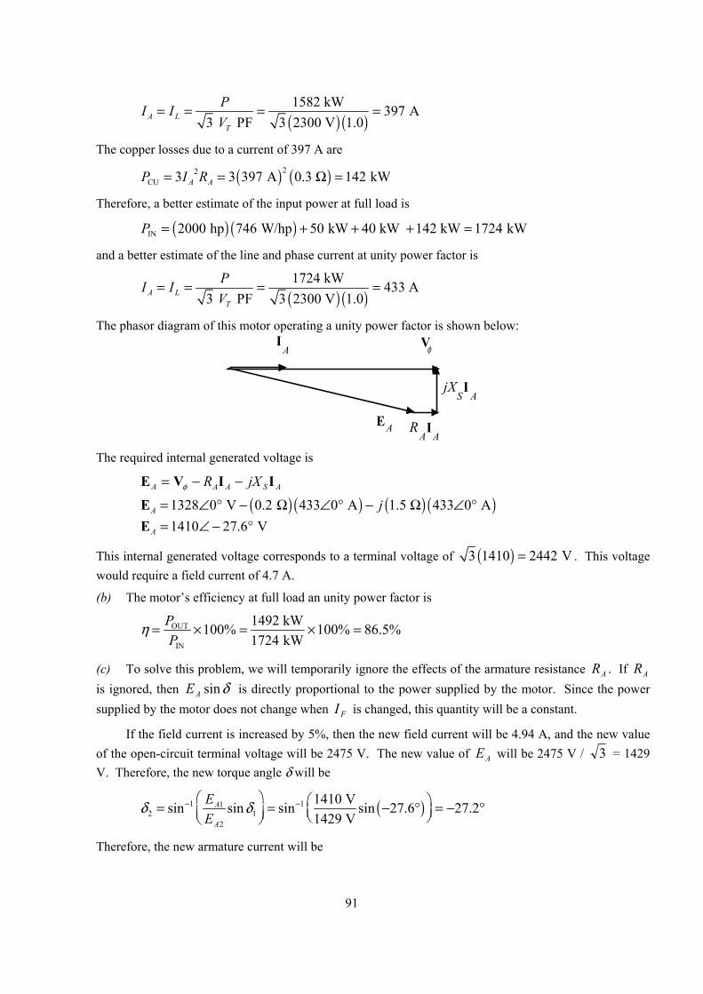
91
( ) ( )1582 kW 397 A
3 PF 3 2300 V 1.0A LT
PI IV
= = = =
The copper losses due to a current of 397 A are
( ) ( )22CU 3 3 397 A 0.3 142 kWA AP I R= = Ω =
Therefore, a better estimate of the input power at full load is
( ) ( )IN 2000 hp 746 W/hp 50 kW 40 kW 142 kW 1724 kWP = + + + =
and a better estimate of the line and phase current at unity power factor is
( ) ( )1724 kW 433 A
3 PF 3 2300 V 1.0A LT
PI IV
= = = =
The phasor diagram of this motor operating a unity power factor is shown below:
jX SI
A
V φI A
EA I A
R A
The required internal generated voltage is
ASAAA jXR IIVE −−= φ
( ) ( ) ( ) ( )1328 0 V 0.2 433 0 A 1.5 433 0 AA j= ∠ ° − Ω ∠ ° − Ω ∠ °E 1410 27.6 VA = ∠ − °E
This internal generated voltage corresponds to a terminal voltage of ( )3 1410 2442 V= . This voltage would require a field current of 4.7 A.
(b) The motor’s efficiency at full load an unity power factor is
OUT
IN
1492 kW100% 100% 86.5%1724 kW
PP
η = × = × =
(c) To solve this problem, we will temporarily ignore the effects of the armature resistance AR . If AR is ignored, then δsinAE is directly proportional to the power supplied by the motor. Since the power supplied by the motor does not change when FI is changed, this quantity will be a constant.
If the field current is increased by 5%, then the new field current will be 4.94 A, and the new value of the open-circuit terminal voltage will be 2475 V. The new value of AE will be 2475 V / 3 = 1429 V. Therefore, the new torque angle δ will be
( )1 112 1
2
1410 Vsin sin sin sin 27.6 27.21429 V
A
A
EE
δ δ− − = = − ° = − °
Therefore, the new armature current will be
92
1328 0 V-1429 -27.2 V 428.6 6.3 A
0.3 1.5 A
AA SR jX jφ − ∠ ° ∠ °= = = ∠ °+ + Ω
V EI
The new current is about the same as before, but the phase angle has become positive. The new power factor is cos 6.3° = 0.994 leading, and the reactive power supplied by the motor is
( ) ( ) ( )3 sin 3 2300 V 428.6 A 0.110 187 kVART LQ V I θ= = =
(d) The maximum torque possible at unity power factor (ignoring the effects if AR ) is:
( ) ( )
( ) ( )ind,max
3 3 1328 V 1410 V9940 N m
1 min 2 rad 3600 r/min 1.5 60 s 1 r
A
m S
V EX
φτ πω= = = ⋅
Ω
At a power factor of 0.8 leading, the current flow will be
( ) ( )
IN 1724 kW 541 A3 PF 3 2300 V 0.8A L
T
PI IV
= = = =
so 541 36.87 AA = ∠ °I . The internal generated voltage at 0.8 PF leading is
ASAAA jXR IIVE −−= φ
( ) ( ) ( ) ( )1328 0 V 0.2 541 36.87 A 1.5 541 36.87 AA j= ∠ ° − Ω ∠ ° − Ω ∠ °E 1870 22.4 VA = ∠ − °E
Therefore, the maximum torque at a power factor of 0.8 leading is
( ) ( )
( ) ( )ind,max
3 3 1328 V 1870 V13,180 N m
1 min 2 rad 3600 r/min 1.5 60 s 1 r
A
m S
V EX
φτ πω= = = ⋅
Ω
5-21. Plot the V-curves ( I A versus IF ) for the synchronous motor of Problem 5-20 at no-load, half-load, and full-load conditions. (Note that an electronic version of the open-circuit characteristics in Figure P5-3 is available at the book’s Web site. It may simplify the calculations required by this problem. Also, you may assume that AR is negligible for this calculation.)
SOLUTION The input power at no-load, half-load and full-load conditions is given below. Note that we are assuming that AR is negligible in each case.
kW 90kW 40 kW 50nlIN, =+=P
( ) ( ) kW 836kW 40 kW 50W/hp 746 hp 1000halfIN, =++=P
( ) ( ) kW 1582kW 40 kW 50W/hp 746 hp 2000IN,full =++=P
If the power factor is adjusted to unity, then armature currents will be
( )( ) A 6.220.1V 23003
kW 90 PF 3nl, ===
TA V
PI
( )( ) A 2100.1V 23003
kW 836 PF 3fl, ===
TA V
PI
93
( )( ) A 3970.1V 23003
kW 1582 PF 3fl, ===
TA V
PI
The corresponding internal generated voltages at unity power factor are:
ASA jX IVE −= φ
( )( ) V 46.14.1328A 06.22 5.1V 01328nl, °−∠=°∠Ω−°∠= jAE
( )( ) V 3.131365A 0210 5.1V 01328half, °−∠=°∠Ω−°∠= jAE
( )( ) V 1.241455A 0397 5.1V 01328full, °−∠=°∠Ω−°∠= jAE
These values of AE and δ at unity power factor can serve as reference points in calculating the synchronous motor V-curves. The MATLAB program to solve this problem is shown below:
% M-file: prob5_21.m% M-file create a plot of armature current versus field% current for the synchronous motor of Problem 5-20 at% no-load, half-load, and full-load.
% First, initialize the field current values (21 values% in the range 3.8-5.8 A)If = 2.5:0.1:8;
% Get the OCCload p53.occ;if_values = p53(:,1);vt_values = p53(:,2);
% Now initialize all other valuesXs = 1.5; % Synchronous reactanceVp = 1328; % Phase voltage
% The following values of Ea and delta are for unity% power factor. They will serve as reference values% when calculating the V-curves.d_nl = -1.46 * pi/180; % delta at no-loadd_half = -13.3 * pi/180; % delta at half-loadd_full = -24.1 * pi/180; % delta at full-loadEa_nl = 1328.4; % Ea at no-loadEa_half = 1365; % Ea at half-loadEa_full = 1455; % Ea at full-load
%%%%%%%%%%%%%%%%%%%%%%%%%%%%%%%%%%%%%%%%%%%%%%%%%%%%%%% Calculate the actual Ea corresponding to each level% of field current%%%%%%%%%%%%%%%%%%%%%%%%%%%%%%%%%%%%%%%%%%%%%%%%%%%%%%Ea = interp1(if_values,vt_values,If) / sqrt(3);
%%%%%%%%%%%%%%%%%%%%%%%%%%%%%%%%%%%%%%%%%%%%%%%%%%%%%%% Calculate the armature currents associated with% each value of Ea for the no-load case.%%%%%%%%%%%%%%%%%%%%%%%%%%%%%%%%%%%%%%%%%%%%%%%%%%%%%%% First, calculate delta.delta = asin ( Ea_nl ./ Ea .* sin(d_nl) );

94
% Calculate the phasor EaEa2 = Ea .* (cos(delta) + j .* sin(delta));
% Now calculate IaIa_nl = ( Vp - Ea2 ) / (j * Xs);
%%%%%%%%%%%%%%%%%%%%%%%%%%%%%%%%%%%%%%%%%%%%%%%%%%%%%%% Calculate the armature currents associated with% each value of Ea for the half-load case.%%%%%%%%%%%%%%%%%%%%%%%%%%%%%%%%%%%%%%%%%%%%%%%%%%%%%%% First, calculate delta.delta = asin ( Ea_half ./ Ea .* sin(d_half) );
% Calculate the phasor EaEa2 = Ea .* (cos(delta) + j .* sin(delta));
% Now calculate IaIa_half = ( Vp - Ea2 ) / (j * Xs);
%%%%%%%%%%%%%%%%%%%%%%%%%%%%%%%%%%%%%%%%%%%%%%%%%%%%%%% Calculate the armature currents associated with% each value of Ea for the full-load case.%%%%%%%%%%%%%%%%%%%%%%%%%%%%%%%%%%%%%%%%%%%%%%%%%%%%%%% First, calculate delta.delta = asin ( Ea_full ./ Ea .* sin(d_full) );
% Calculate the phasor EaEa2 = Ea .* (cos(delta) + j .* sin(delta));
% Now calculate IaIa_full = ( Vp - Ea2 ) / (j * Xs);
%%%%%%%%%%%%%%%%%%%%%%%%%%%%%%%%%%%%%%%%%%%%%%%%%%%%%%% Plot the v-curves%%%%%%%%%%%%%%%%%%%%%%%%%%%%%%%%%%%%%%%%%%%%%%%%%%%%%%plot(If,abs(Ia_nl),'k-','Linewidth',2.0);hold on;plot(If,abs(Ia_half),'b--','Linewidth',2.0);plot(If,abs(Ia_full),'r:','Linewidth',2.0);xlabel('\bfField Current (A)');ylabel('\bfArmature Current (A)');title ('\bfSynchronous Motor V-Curve');grid on;
The resulting plot is shown below. The flattening visible to the right of the V-curves is due to magnetic saturation in the machine.
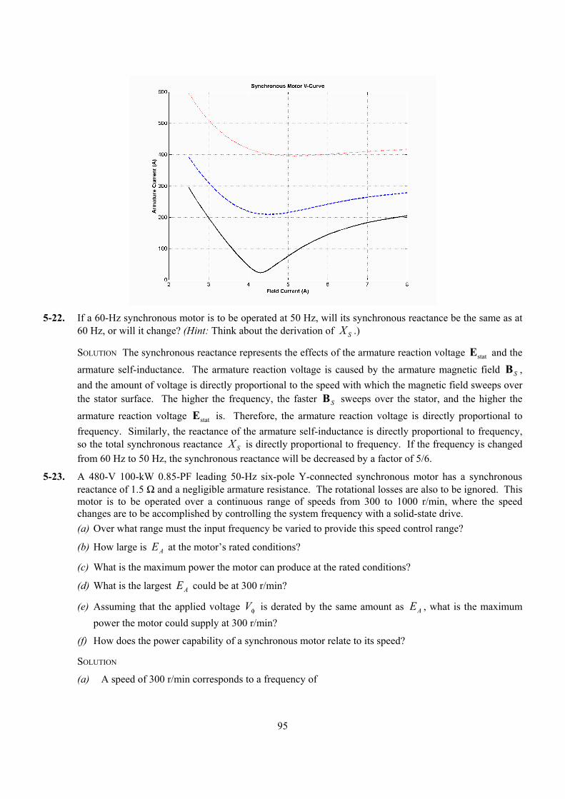
95
5-22. If a 60-Hz synchronous motor is to be operated at 50 Hz, will its synchronous reactance be the same as at
60 Hz, or will it change? (Hint: Think about the derivation of X S .)
SOLUTION The synchronous reactance represents the effects of the armature reaction voltage statE and the armature self-inductance. The armature reaction voltage is caused by the armature magnetic field SB , and the amount of voltage is directly proportional to the speed with which the magnetic field sweeps over the stator surface. The higher the frequency, the faster SB sweeps over the stator, and the higher the armature reaction voltage statE is. Therefore, the armature reaction voltage is directly proportional to frequency. Similarly, the reactance of the armature self-inductance is directly proportional to frequency, so the total synchronous reactance X S is directly proportional to frequency. If the frequency is changed from 60 Hz to 50 Hz, the synchronous reactance will be decreased by a factor of 5/6.
5-23. A 480-V 100-kW 0.85-PF leading 50-Hz six-pole Y-connected synchronous motor has a synchronous reactance of 1.5 Ω and a negligible armature resistance. The rotational losses are also to be ignored. This motor is to be operated over a continuous range of speeds from 300 to 1000 r/min, where the speed changes are to be accomplished by controlling the system frequency with a solid-state drive. (a) Over what range must the input frequency be varied to provide this speed control range?
(b) How large is EA at the motor’s rated conditions?
(c) What is the maximum power the motor can produce at the rated conditions?
(d) What is the largest EA could be at 300 r/min?
(e) Assuming that the applied voltage Vφ is derated by the same amount as EA , what is the maximum power the motor could supply at 300 r/min?
(f) How does the power capability of a synchronous motor relate to its speed?
SOLUTION
(a) A speed of 300 r/min corresponds to a frequency of
96
( ) ( ) Hz15
1206 r/min 300
120=== Pnf m
e
A speed of 1000 r/min corresponds to a frequency of
( ) ( ) Hz50
1206 r/min 1000
120=== Pnf m
e
The frequency must be controlled in the range 15 to 50 Hz.
(b) The armature current at rated conditions is
( ) ( )
100 kW 141.5 A3 PF 3 480 V 0.85A L
T
PI IV
= = = =
so A 8.315.141 °∠=AI . This machine is Y-connected, so the phase voltage is φV = 480 / 3 = 277 V. The internal generated voltage is
ASAAA jXR IIVE −−= φ
( ) ( )277 0 V 1.5 141.5 31.8 AA j= ∠ ° − Ω ∠ °E V 9.24429 °−∠=AE
So AE = 429 V at rated conditions.
(c) The maximum power that the motor can produce at rated speed with the value of AE from part (b) is
( ) ( )
max
3 3 277 V 429 V238 kW
1.5 A
S
V EP
Xφ= = =
Ω
(d) Since AE must be decreased linearly with frequency, the maximum value at 300 r/min would be
( ) V 129V 429 Hz50 Hz15
300, =
=AE
(e) If the applied voltage φV is derated by the same amount as AE , then φV = (15/50)(277) = 83.1 V.
Also, note that SX = (15/50)(1.5 Ω) = 0.45 Ω. The maximum power that the motor could supply would be
( ) ( ) kW 5.71
0.45V 291 V 3.183 3
max =Ω
==S
A
XEV
P φ
(f) As we can see by comparing the results of (c) and (e), the power-handling capability of the synchronous motor varies linearly with the speed of the motor.
5-24. A 208-V Y-connected synchronous motor is drawing 50 A at unity power factor from a 208-V power system. The field current flowing under these conditions is 2.7 A. Its synchronous reactance is 0.8 Ω. Assume a linear open-circuit characteristic. (a) Find the torque angle δ.
(b) How much field current would be required to make the motor operate at 0.78 PF leading?
(c) What is the new torque angle in part (b)?
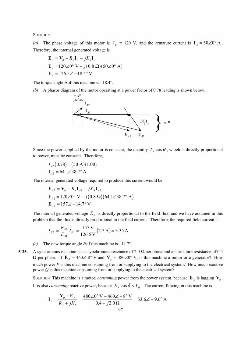
97
SOLUTION
(a) The phase voltage of this motor is φV = 120 V, and the armature current is A 050 °∠=AI . Therefore, the internal generated voltage is
ASAAA jXR IIVE −−= φ
( ) ( )120 0 V 0.8 50 0 AA j= ∠ ° − Ω ∠ °E V 4.185.126 °−∠=AE
The torque angle δ of this machine is –18.4°.
(b) A phasor diagram of the motor operating at a power factor of 0.78 leading is shown below.
V φ
EA1
jX S
I A
EA2
IA2
IA1
∝ P
∝ P
Since the power supplied by the motor is constant, the quantity θ cos AI , which is directly proportional
to power, must be constant. Therefore,
( ) ( ) ( )2 0.78 50 A 1.00AI = A 7.381.642 °∠=AI
The internal generated voltage required to produce this current would be
222 ASAAA jXR IIVE −−= φ
( ) ( )2 120 0 V 0.8 64.1 38.7 AA j= ∠ ° − Ω ∠ °E V 7.141572 °−∠=AE
The internal generated voltage AE is directly proportional to the field flux, and we have assumed in this problem that the flux is directly proportional to the field current. Therefore, the required field current is
( ) A 35.3A 7.2V 126.5
V 1571
1
22 === F
A
AF I
EEI
(c) The new torque angle δ of this machine is –14.7°.
5-25. A synchronous machine has a synchronous reactance of 2.0 Ω per phase and an armature resistance of 0.4 Ω per phase. If E A = 460∠-8° V and φV = 480∠0° V, is this machine a motor or a generator? How much power P is this machine consuming from or supplying to the electrical system? How much reactive power Q is this machine consuming from or supplying to the electrical system?
SOLUTION This machine is a motor, consuming power from the power system, because AE is lagging φV .
It is also consuming reactive power, because φδ VEA <cos . The current flowing in this machine is
A 6.96.33 0.24.0
V 8460V 0480 °−∠=Ω+
°−∠−°∠=+−
=jjXR SA
AA
EVI φ
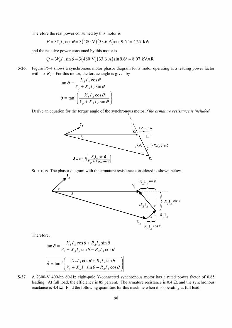
98
Therefore the real power consumed by this motor is
( ) ( )3 cos 3 480 V 33.6 A cos9.6 47.7 kWAP V Iφ θ= = ° =
and the reactive power consumed by this motor is
( ) ( )3 sin 3 480 V 33.6 A sin 9.6 8.07 kVARAQ V Iφ θ= = ° =
5-26. Figure P5-4 shows a synchronous motor phasor diagram for a motor operating at a leading power factor with no RA . For this motor, the torque angle is given by
θ
θδφ sin
cos = tanAS
AS
IXVIX
+
+ θθδ
φ sin cos tan= 1-
AS
AS
IXVIX
Derive an equation for the torque angle of the synchronous motor if the armature resistance is included.
SOLUTION The phasor diagram with the armature resistance considered is shown below.
jX S
I A
V φ
I A
EA
I A
R A
I A
R A
cos θ
θ
θ
θ
X S
I A
sin θ
X S
I A
cos θ
δ
Therefore,
θθ
θθδφ cossin
sincostanAAAS
AAAS
IRIXVIRIX
−++=
−++= −
θθθθδ
φ cossinsincostan 1
AAAS
AAAS
IRIXVIRIX
5-27. A 2300-V 400-hp 60-Hz eight-pole Y-connected synchronous motor has a rated power factor of 0.85 leading. At full load, the efficiency is 85 percent. The armature resistance is 0.4 Ω, and the synchronous reactance is 4.4 Ω. Find the following quantities for this machine when it is operating at full load:
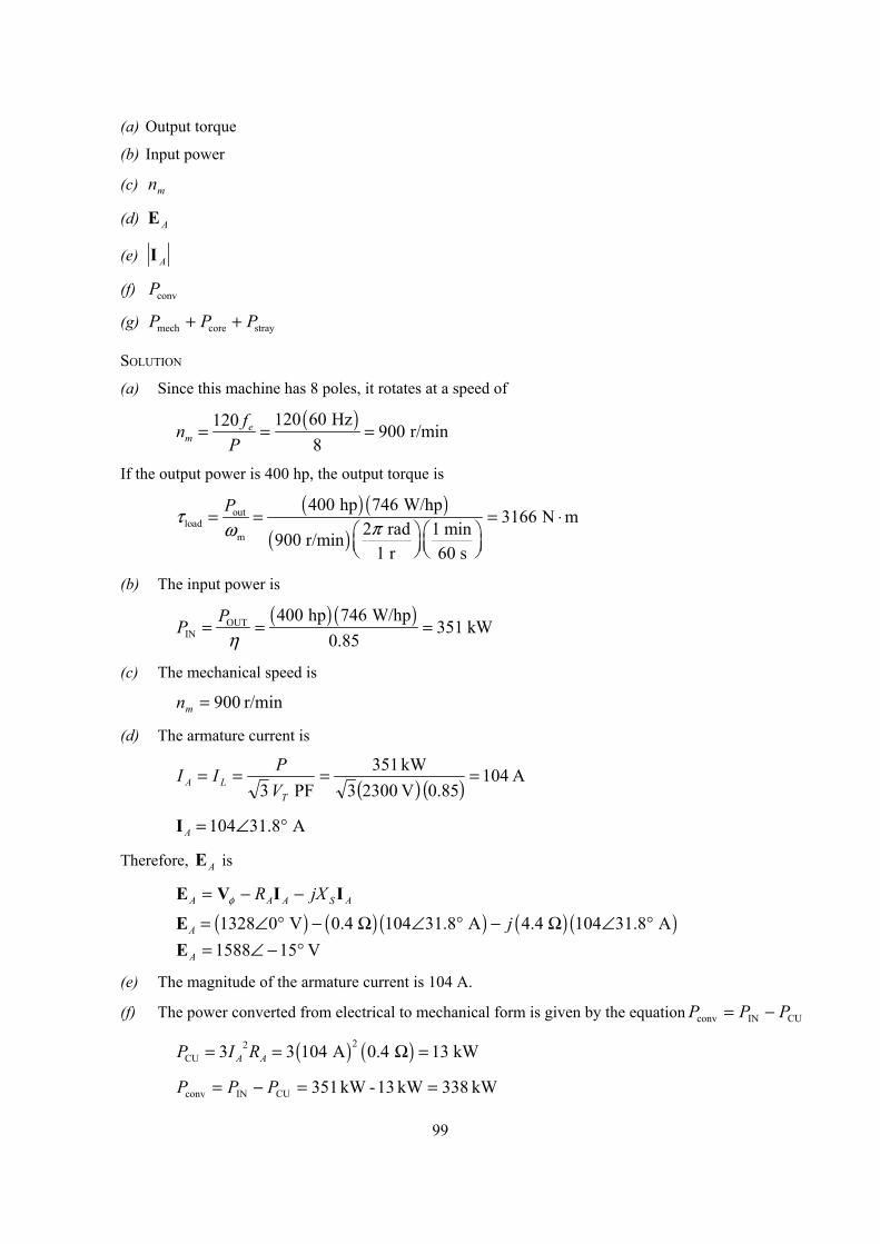
99
(a) Output torque
(b) Input power
(c) mn
(d) E A
(e) I A
(f) Pconv
(g) P P Pmech core stray+ +
SOLUTION
(a) Since this machine has 8 poles, it rotates at a speed of
( )120 60 Hz120 900 r/min
8e
mfn
P= = =
If the output power is 400 hp, the output torque is
( ) ( )
( )out
loadm
400 hp 746 W/hp3166 N m
2 rad 1 min900 r/min1 r 60 s
Pτ πω= = = ⋅
(b) The input power is
( ) ( )OUT
IN400 hp 746 W/hp
351 kW0.85
PPη
= = =
(c) The mechanical speed is
r/min 900=mn
(d) The armature current is
( ) ( ) A 10485.0 V 23003
kW 351 PF 3
====T
LA VPII
104 31.8 AA = ∠ °I
Therefore, AE is
ASAAA jXR IIVE −−= φ
( ) ( ) ( ) ( ) ( )1328 0 V 0.4 104 31.8 A 4.4 104 31.8 AA j= ∠ ° − Ω ∠ ° − Ω ∠ °E V 151588 °−∠=AE
(e) The magnitude of the armature current is 104 A.
(f) The power converted from electrical to mechanical form is given by the equation CUINconv PPP −=
( ) ( )22CU 3 3 104 A 0.4 13 kWA AP I R= = Ω =
kW 338kW 13-kW 351CUINconv ==−= PPP
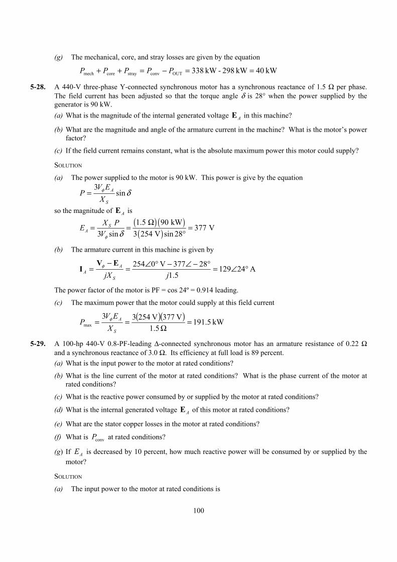
100
(g) The mechanical, core, and stray losses are given by the equation
kW 40kW 298-kW 338OUTconvstraycoremech ==−=++ PPPPP
5-28. A 440-V three-phase Y-connected synchronous motor has a synchronous reactance of 1.5 Ω per phase. The field current has been adjusted so that the torque angle δ is 28° when the power supplied by the generator is 90 kW. (a) What is the magnitude of the internal generated voltage E A in this machine?
(b) What are the magnitude and angle of the armature current in the machine? What is the motor’s power factor?
(c) If the field current remains constant, what is the absolute maximum power this motor could supply?
SOLUTION
(a) The power supplied to the motor is 90 kW. This power is give by the equation
δφ sin3
S
A
XEV
P =
so the magnitude of E A is
( ) ( )
( )1.5 90 kW 377 V
3 sin 3 254 V sin 28S
AX PE
Vφ δΩ
= = =°
(b) The armature current in this machine is given by
A 241295.1
28377V 0254 °∠=°−∠−°∠=−
=jjX S
AA
EVI φ
The power factor of the motor is PF = cos 24º = 0.914 leading.
(c) The maximum power that the motor could supply at this field current
( )( ) kW 5.191
5.1V 377V 25433
max =Ω
==S
A
XEV
P φ
5-29. A 100-hp 440-V 0.8-PF-leading ∆-connected synchronous motor has an armature resistance of 0.22 Ω and a synchronous reactance of 3.0 Ω. Its efficiency at full load is 89 percent. (a) What is the input power to the motor at rated conditions?
(b) What is the line current of the motor at rated conditions? What is the phase current of the motor at rated conditions?
(c) What is the reactive power consumed by or supplied by the motor at rated conditions?
(d) What is the internal generated voltage E A of this motor at rated conditions?
(e) What are the stator copper losses in the motor at rated conditions?
(f) What is Pconv at rated conditions?
(g) If EA is decreased by 10 percent, how much reactive power will be consumed by or supplied by the motor?
SOLUTION
(a) The input power to the motor at rated conditions is
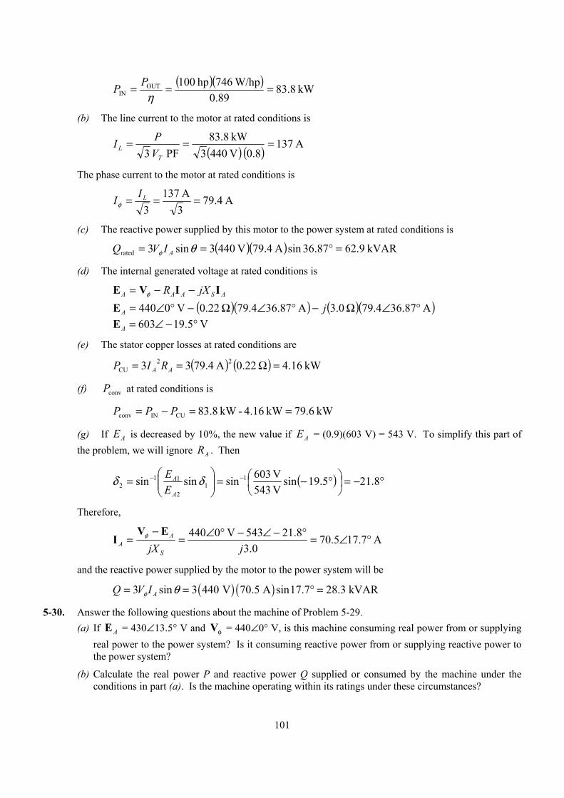
101
( )( ) kW 8.83
0.89W/hp 746hp 100OUT
IN ===η
PP
(b) The line current to the motor at rated conditions is
( ) ( ) A 1378.0 V 4403
kW 83.8 PF 3
===T
L VPI
The phase current to the motor at rated conditions is
A 4.793A 137
3=== LIIφ
(c) The reactive power supplied by this motor to the power system at rated conditions is
( )( ) kVAR 9.6287.36sinA 4.79V 4403sin3rated =°== θφ AIVQ
(d) The internal generated voltage at rated conditions is
ASAAA jXR IIVE −−= φ
( )( ) ( )( )A 87.364.79 0.3A 87.364.79 22.0V 0440 °∠Ω−°∠Ω−°∠= jAE V 5.19603 °−∠=AE
(e) The stator copper losses at rated conditions are
( ) ( ) kW 16.4 22.0A 4.7933 22CU =Ω== AA RIP
(f) convP at rated conditions is
kW 6.97kW 4.16-kW 8.83CUINconv ==−= PPP
(g) If AE is decreased by 10%, the new value if AE = (0.9)(603 V) = 543 V. To simplify this part of the problem, we will ignore AR . Then
( ) °−=
°−=
= −− 8.215.19sin
V 543V 603sinsinsin 1
12
112 δδ
A
A
EE
Therefore,
A 7.175.700.3
8.21543V 0440 °∠=°−∠−°∠=−
=jjX S
AA
EVI φ
and the reactive power supplied by the motor to the power system will be
( ) ( )3 sin 3 440 V 70.5 A sin17.7 28.3 kVARAQ V Iφ θ= = ° =
5-30. Answer the following questions about the machine of Problem 5-29. (a) If E A = 430∠13.5° V and Vφ = 440∠0° V, is this machine consuming real power from or supplying
real power to the power system? Is it consuming reactive power from or supplying reactive power to the power system?
(b) Calculate the real power P and reactive power Q supplied or consumed by the machine under the conditions in part (a). Is the machine operating within its ratings under these circumstances?
102
(c) If E A = 470∠-12° V and Vφ = 440∠0° V, is this machine consuming real power from or supplying real power to the power system? Is it consuming reactive power from or supplying reactive power to the power system?
(d) Calculate the real power P and reactive power Q supplied or consumed by the machine under the conditions in part (c). Is the machine operating within its ratings under these circumstances?
SOLUTION
(a) This machine is a generator supplying real power to the power system, because AE is ahead of φV .
It is consuming reactive power because φδ VEA <cos .
(b) This machine is acting as a generator, and the current flow in these conditions is
A 5.162.340.322.0
V 04405.13430 °∠=+
°∠−°∠=+−
=jjXR SA
AA
φVEI
The real power supplied by this machine is
( ) ( ) ( )3 cos 3 440 V 34.2 A cos 16.5 43.3 kWAP V Iφ θ= = − ° =
The reactive power supplied by this machine is
( )( ) ( ) kVAR 8.125.16sinA 4.23V 4403sin3 −=°−== θφ AIVQ
(c) This machine is a motor consuming real power from the power system, because AE is behind φV .
It is supplying reactive power because φδ VEA >cos .
(d) This machine is acting as a motor, and the current flow in these conditions is
A 6.151.330.322.0
12470V 0440 °∠=+
°−∠−°∠=+−
=jjXR SA
AA
EVI φ
The real power consumed by this machine is
( ) ( ) ( )3 cos 3 440 V 33.1 A cos 15.6 42.1 kWAP V Iφ θ= = ° =
The reactive power supplied by this machine is
( ) ( ) ( )3 sin 3 440 V 33.1 A sin 15.6 11.7 kVARAQ V Iφ θ= = ° = +
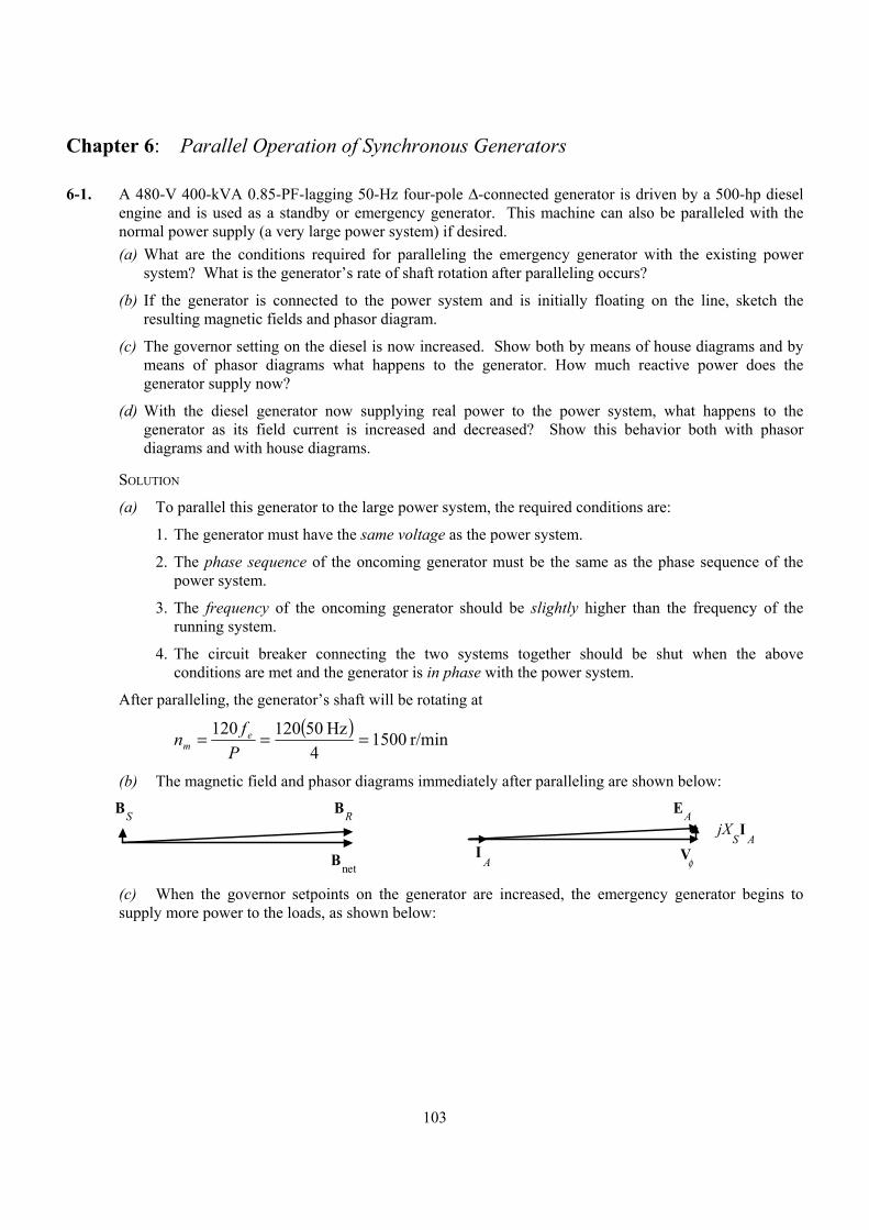
103
Chapter 6: Parallel Operation of Synchronous Generators
6-1. A 480-V 400-kVA 0.85-PF-lagging 50-Hz four-pole ∆-connected generator is driven by a 500-hp diesel engine and is used as a standby or emergency generator. This machine can also be paralleled with the normal power supply (a very large power system) if desired. (a) What are the conditions required for paralleling the emergency generator with the existing power
system? What is the generator’s rate of shaft rotation after paralleling occurs?
(b) If the generator is connected to the power system and is initially floating on the line, sketch the resulting magnetic fields and phasor diagram.
(c) The governor setting on the diesel is now increased. Show both by means of house diagrams and by means of phasor diagrams what happens to the generator. How much reactive power does the generator supply now?
(d) With the diesel generator now supplying real power to the power system, what happens to the generator as its field current is increased and decreased? Show this behavior both with phasor diagrams and with house diagrams.
SOLUTION
(a) To parallel this generator to the large power system, the required conditions are:
1. The generator must have the same voltage as the power system.
2. The phase sequence of the oncoming generator must be the same as the phase sequence of the power system.
3. The frequency of the oncoming generator should be slightly higher than the frequency of the running system.
4. The circuit breaker connecting the two systems together should be shut when the above conditions are met and the generator is in phase with the power system.
After paralleling, the generator’s shaft will be rotating at
( ) r/min 1500
4 Hz50120120 ===
Pfn e
m
(b) The magnetic field and phasor diagrams immediately after paralleling are shown below:
I A V φ
EAjX
SI
A
BRBS
Bnet (c) When the governor setpoints on the generator are increased, the emergency generator begins to
supply more power to the loads, as shown below:
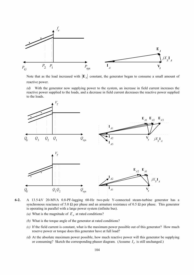
104
I A V φ
EA
jX SI
A
fe
P1P2 PsysPG
Note that as the load increased with AE constant, the generator began to consume a small amount of reactive power.
(d) With the generator now supplying power to the system, an increase in field current increases the reactive power supplied to the loads, and a decrease in field current decreases the reactive power supplied to the loads.
V φ
EA1
jX S
I A
QsysQG
Q2 Q1Q3
EA2 EA3
I A3
I A2
I A1
V φ
EA1
jX S
I A
QsysQG Q2Q1
EA2
I A2
I A1
VT
VT
6-2. A 13.5-kV 20-MVA 0.8-PF-lagging 60-Hz two-pole Y-connected steam-turbine generator has a
synchronous reactance of 5.0 Ω per phase and an armature resistance of 0.5 Ω per phase. This generator is operating in parallel with a large power system (infinite bus). (a) What is the magnitude of EA at rated conditions?
(b) What is the torque angle of the generator at rated conditions?
(c) If the field current is constant, what is the maximum power possible out of this generator? How much reserve power or torque does this generator have at full load?
(d) At the absolute maximum power possible, how much reactive power will this generator be supplying or consuming? Sketch the corresponding phasor diagram. (Assume IF is still unchanged.)
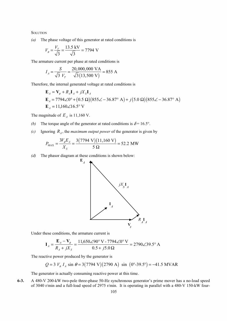
105
SOLUTION
(a) The phase voltage of this generator at rated conditions is
13.5 kV 7794 V
3 3TVVφ = = =
The armature current per phase at rated conditions is
( )
20,000,000 VA 855 A3 3 13,500 VA
T
SIV
= = =
Therefore, the internal generated voltage at rated conditions is
ASAAA jXR IIVE ++= φ
( ) ( ) ( ) ( )7794 0 0.5 855 36.87 A 5.0 855 36.87 AA j= ∠ ° + Ω ∠ − ° + Ω ∠ − °E V 5.16160,11 °∠=AE
The magnitude of AE is 11,160 V.
(b) The torque angle of the generator at rated conditions is δ = 16.5°.
(c) Ignoring AR , the maximum output power of the generator is given by
( ) ( )
MAX
3 3 7794 V 11,160 V52.2 MW
5 A
S
V EP
Xφ= = =
Ω
(d) The phasor diagram at these conditions is shown below:
jX S
I A
V φ
I A
EA
I A
R A
Under these conditions, the armature current is
A 5.392790 5.00.5
V 07794 - V 90650,11 °∠=Ω+
°∠°∠=+−
=jjXR SA
AA
φVEI
The reactive power produced by the generator is
( ) ( ) ( )3 sin 3 7794 V 2790 A sin 0 -39.5 41.5 MVARAQ V Iφ θ= = ° ° = −
The generator is actually consuming reactive power at this time.
6-3. A 480-V 200-kW two-pole three-phase 50-Hz synchronous generator’s prime mover has a no-load speed of 3040 r/min and a full-load speed of 2975 r/min. It is operating in parallel with a 480-V 150-kW four-
106
pole 50-Hz synchronous generator whose prime mover has a no-load speed of 1500 r/min and a full-load speed of 1485 r/min. The loads supplied by the two generators consist of 200 kW at 0.85 PF lagging. (a) Calculate the speed droops of generator 1 and generator 2.
(b) Find the operating frequency of the power system.
(c) Find the power being supplied by each of the generators in this system.
(d) If VT is 460 V, what must the generator’s operators do to correct for the low terminal voltage?
SOLUTION The no-load frequency of generator 1 corresponds to a frequency of
( )( ) Hz67.50
1202r/min 3040
120
nl1 === Pnf m
The full-load frequency of generator 1 corresponds to a frequency of
( )( ) Hz58.49
1202r/min 2975
120
fl1 === Pnf m
The no-load frequency of generator 2 corresponds to a frequency of
( )( ) Hz00.50
1204r/min 1500
120
nl2 === Pnf m
The full-load frequency of generator 2 corresponds to a frequency of
( )( ) Hz50.49
1204r/min 1485
120
fl2 === Pnf m
(a) The speed droop of generator 1 is given by
%18.2%100r/min 2975
r/min 2975-r/min 3040%100SDfl
flnl1 =×=×−=
nnn
The speed droop of generator 2 is given by
%01.1%100r/min 1485
r/min 1485-r/min 5001%100SDfl
flnl2 =×=×−=
nnn
(b) The power supplied by generator 1 is given by
( )sysnl111 ffsP P −=
and the power supplied by generator 1 is given by
( )sysnl222 ffsP P −=
The power curve’s slope for generator 1 is
MW/Hz185.0 Hz49.58- Hz67.50
kW 200
flnl1 ==
−=
ffPsP
The power curve’s slope for generator 1 is
MW/Hz300.0 Hz49.50- Hz00.50
kW 501
flnl2 ==
−=
ffPsP
107
The no-load frequency of generator 1 is 50.67 Hz and the no-load frequency of generator 2 is 50 Hz. The total power that they must supply is 200 kW, so the system frequency can be found from the equations
21LOAD PPP += ( ) ( )sysnl22sysnl11LOAD ffsffsP PP −+−=
( )( ) ( )( )syssys - Hz00.50 MW/Hz300.0- Hz67.50 MW/Hz185.0kW 200 ff +=
( ) ( ) syssys MW/Hz300.0-kW 000,15 MW/Hz185.0-kW 9374kW 200 ff +=
( ) kW 200-kW 000,15kW 9374 MW/Hz485.0 sys +=f
Hz843.49 MW/Hz485.0
kW 174,24sys ==f
(c) The power supplied by generator 1 is
( ) ( )( ) kW 153 Hz49.843- Hz67.50 MW/Hz185.0sysnl111 ==−= ffsP P
The power supplied by generator 2 is
( ) ( )( ) kW 47 Hz49.843- Hz00.50 MW/Hz300.0sysnl222 ==−= ffsP P
(d) If the terminal voltage is 460 V, the operators of the generators must increase the field currents on both generators simultaneously. That action will increase the terminal voltages of the system without changing the power sharing between the generators.
6-4. Three physically identical synchronous generators are operating in parallel. They are all rated for a full load of 3 MW at 0.8 PF lagging. The no-load frequency of generator A is 61 Hz, and its speed droop is 3.4 percent. The no-load frequency of generator B is 61.5 Hz, and its speed droop is 3 percent. The no-load frequency of generator C is 60.5 Hz, and its speed droop is 2.6 percent. (a) If a total load consisting of 7 MW is being supplied by this power system, what will the system
frequency be and how will the power be shared among the three generators?
(b) Create a plot showing the power supplied by each generator as a function of the total power supplied to all loads (you may use MATLAB to create this plot). At what load does one of the generators exceed its ratings? Which generator exceeds its ratings first?
(c) Is this power sharing in (a) acceptable? Why or why not?
(d) What actions could an operator take to improve the real power sharing among these generators?
SOLUTION
(a) Speed droop is defined as
%100%100SDfl
flnl
fl
flnl ×−=×−=f
ffn
nn
so 1
100SD
nlfl
+= ff
Thus, the full-load frequencies of generators A, B, and C are
108
Hz0.591
1003.4
Hz61
1100SDA
Anl,Afl, =
+=
+=
ff
Hz71.591
1003.0
Hz5.61
1100SDB
Bnl,Bfl, =
+=
+=
ff
Hz97.581
1002.6
Hz5.60
1100SDC
nl,Cfl,C =
+=
+=
ff
and the slopes of the power-frequency curves are:
MW/Hz5.1 Hz2
MW3 ==PAS
MW/Hz676.1 Hz1.79
MW3 ==PBS
MW/Hz961.1 Hz1.53
MW3 ==PCS
(a) The total load is 7 MW, so the system frequency is ( ) ( ) ( )sysnlCsysnlBsysnlALOAD ffsffsffsP PCPBPA −+−+−=
( ) ( ) ( ) ( ) ( ) ( )sys sys sys7 MW 1.5 61.0- 1.676 61.5- 1.961 60.5-f f f= + +
syssyssys .9611-64.118.6761-07.103.51-5.91 MW7 fff ++=
2.306137.5 sys =f
Hz61.59sys =f
The power supplied by each generator will be
( ) ( )( ) MW09.2 Hz59.61- Hz1.06 MW/Hz.51sysnlA ==−= ffsP PAA
( ) ( )( ) MW17.3 Hz59.61- Hz1.56 MW/Hz.6761sysnlB ==−= ffsP PBB
( ) ( )( ) MW74.1 Hz59.61- Hz0.56 MW/Hz.9611sysnlC ==−= ffsP PCC
(b) The equation in part (a) can be re-written slightly to express system frequency as a function of load.
( )( ) ( )( ) ( )( )syssyssysLOAD -0.56.9611-1.56.6761-1.065.1 fffP ++=
syssyssysLOAD .9611-64.118.6761-07.103.51-5.91 fffP ++=
LOADsys 2.313137.5 Pf −=
137.5
2.313 LOADsys
Pf −=
A MATLAB program that uses this equation to determine the power sharing among the generators as a function of load is shown below:
% M-file: prob6_4b.m% M-file to calculate and plot the power sharing among
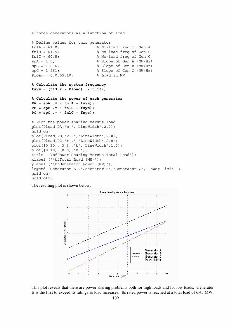
109
% three generators as a function of load.
% Define values for this generatorfnlA = 61.0; % No-load freq of Gen AfnlB = 61.5; % No-load freq of Gen BfnlC = 60.5; % No-load freq of Gen CspA = 1.5; % Slope of Gen A (MW/Hz)spB = 1.676; % Slope of Gen B (MW/Hz)spC = 1.961; % Slope of Gen C (MW/Hz)Pload = 0:0.05:10; % Load in MW
% Calculate the system frequencyfsys = (313.2 - Pload) ./ 5.137;
% Calculate the power of each generatorPA = spA .* ( fnlA - fsys);PB = spB .* ( fnlB - fsys);PC = spC .* ( fnlC - fsys);
% Plot the power sharing versus loadplot(Pload,PA,'b-','LineWidth',2.0);hold on;plot(Pload,PB,'k--','LineWidth',2.0);plot(Pload,PC,'r-.','LineWidth',2.0);plot([0 10],[3 3],'k','LineWidth',1.0);plot([0 10],[0 0],'k:');title ('\bfPower Sharing Versus Total Load');xlabel ('\bfTotal Load (MW)');ylabel ('\bfGenerator Power (MW)');legend('Generator A','Generator B','Generator C','Power Limit');grid on;hold off;
The resulting plot is shown below:
This plot reveals that there are power sharing problems both for high loads and for low loads. Generator
B is the first to exceed its ratings as load increases. Its rated power is reached at a total load of 6.45 MW.
110
On the other hand, Generator C gets into trouble as the total load is reduced. When the total load drops to 2.4 MW, the direction of power flow reverses in Generator C.
(c) The power sharing in (a) is not acceptable, because Generator 2 has exceeded its power limits.
(d) To improve the power sharing among the three generators in (a) without affecting the operating frequency of the system, the operator should decrease the governor setpoints on Generator B while simultaneously increasing them in Generators A and C.
6-5. A paper mill has installed three steam generators (boilers) to provide process steam and also to use some its waste products as an energy source. Since there is extra capacity, the mill has installed three 5-MW turbine generators to take advantage of the situation. Each generator is a 4160-V 6250-kVA 0.85-PF-lagging two-pole Y-connected synchronous generator with a synchronous reactance of 0.75 Ω and an armature resistance of 0.04 Ω. Generators 1 and 2 have a characteristic power-frequency slope sP of 2.5 MW/Hz, and generator 3 has a slope of 3 MW/Hz. (a) If the no-load frequency of each of the three generators is adjusted to 61 Hz, how much power will the
three machines be supplying when actual system frequency is 60 Hz?
(b) What is the maximum power the three generators can supply in this condition without the ratings of one of them being exceeded? At what frequency does this limit occur? How much power does each generator supply at that point?
(c) What would have to be done to get all three generators to supply their rated real and reactive powers at an overall operating frequency of 60 Hz?
(d) What would the internal generated voltages of the three generators be under this condition?
SOLUTION
(a) If the system frequency is 60 Hz and the no-load frequencies of the generators are 61 Hz, then the power supplied by the generators will be
( ) ( ) ( )1 1 nl1 sys 2.5 MW/Hz 61 Hz - 60 Hz 2.5 MWPP s f f= − = =
( ) ( ) ( )2 2 nl2 sys 2.5 MW/Hz 61 Hz - 60 Hz 2.5 MWPP s f f= − = =
( ) ( ) ( )3 3 nl3 sys 3.0 MW/Hz 61 Hz - 60 Hz 3.0 MWPP s f f= − = =
Therefore the total power supplied by the generators is 8 MW.
(b) The maximum power supplied by any one generator is (6250 kVA)(0.85) = 5.31 MW. Generator 3 will be the first machine to reach that limit. Generator 3 will supply this power at a frequency of
( ) ( )sys5.31 MW 3.0 MW/Hz 61 Hz - f=
Hz23.59sys =f
At this point the power supplied by Generators 1 and 2 is
( ) ( )( ) MW425.4 Hz59.23- Hz61 MW/Hz5.2sysnl1121 ==−== ffsPP P
The total power supplied by the generators at this condition is 14.16 MW.
(c) To get each of the generators to supply 5.31 MW at 60 Hz, the no-load frequencies of Generator 1 and Generator 2 would have to be adjusted to 62.12 Hz, and the no-load frequency of Generator 3 would have to be adjusted to 61.77 Hz. The field currents of the three generators must then be adjusted to get them supplying a power factor of 0.85 lagging. At that point, each generator will be supplying its rated real and reactive power.
111
(d) Under the conditions of part (c), which are the rated conditions of the generators, the internal generated voltage would be given by
ASAAA jXR IIVE ++= φ
The phase voltage of the generators is 4160 V / 3 = 2402 V, and since the generators are Y-connected, their rated current is
( ) A 867V 41603
kVA 6250 3
====T
LA VSII
The power factor is 0.85 lagging, so A 8.31867 °−∠=AI . Therefore,
ASAAA jXR IIVE ++= φ
( ) ( ) ( ) ( )2402 0 0.04 867 31.8 A 0.75 867 31.8 AA j= ∠ ° + Ω ∠ − ° + Ω ∠ − °E V 9.102825 °∠=AE
6-6. Two identical 300-kVA 480-V synchronous generators are connected in parallel to supply a load. The prime movers of the two generators happen to have different speed droop characteristics. When the field currents of the two generators are equal, one delivers 200 A at 0.9 PF lagging, while the other delivers 180 A at 0.75 PF lagging. (a) What are the real power and the reactive power supplied by each generator to the load?
(b) What is the overall power factor of the load?
(c) In what direction must the field current on each generator be adjusted in order for them to operate at the same power factor?
SOLUTION
(a) The real and reactive powers are
( ) ( ) ( )1 3 cos 3 480 V 200 A 0.9 150 kWT LP V I θ= = =
( ) ( ) ( )11 3 sin 3 480 V 200 A sin cos 0.9 72.50 kVART LQ V I θ − = = =
( ) ( ) ( )2 3 cos 3 480 V 180 A 0.75 112 kWT LP V I θ= = =
( ) ( ) ( )12 3 sin 3 480 V 180 A sin cos 0.75 99 kVART LQ V I θ − = = =
(b) The overall power factor can be found from the total real and reactive power supplied to the load.
kW 262 kW 112 kW 15021TOT =+=+= PPP
kVAR 171.5 kVAR 99 kVAR 5.7221TOT =+=+= QQQ
The overall power factor is
lagging 837.0tan cosPFTOT
TOT1 =
= −
PQ
(c) The field current of generator 1 should be increased, and the field current of generator 2 should be simultaneously decreased.
6-7. A generating station for a power system consists of four 120-MVA 15-kV 0.85-PF-lagging synchronous generators with identical speed droop characteristics operating in parallel. The governors on the
112
generators’ prime movers are adjusted to produce a 3-Hz drop from no load to full load. Three of these generators are each supplying a steady 75 MW at a frequency of 60 Hz, while the fourth generator (called the swing generator) handles all incremental load changes on the system while maintaining the system's frequency at 60 Hz. (a) At a given instant, the total system loads are 260 MW at a frequency of 60 Hz. What are the no-load
frequencies of each of the system’s generators?
(b) If the system load rises to 290 MW and the generator’s governor set points do not change, what will the new system frequency be?
(c) To what frequency must the no-load frequency of the swing generator be adjusted in order to restore the system frequency to 60 Hz?
(d) If the system is operating at the conditions described in part (c), what would happen if the swing generator were tripped off the line (disconnected from the power line)?
SOLUTION
(a) The full-load power of these generators is ( ) ( ) MW10285.0 MVA120 = and the droop from no-load to full-load is 3 Hz. Therefore, the slope of the power-frequency curve for these four generators is
MW/Hz34 Hz3 MW102 ==Ps
If generators 1, 2, and 3 are supplying 75 MW each, then generator 4 must be supplying 35 MW. The no-load frequency of the first three generators is
( )sysnl111 ffsP P −=
( ) ( )nl175 MW 34 MW/Hz - 60 Hzf=
Hz21.62nl1 =f
The no-load frequency of the fourth generator is
( )sysnl444 ffsP P −=
( ) ( )nl135 MW 34 MW/Hz - 60 Hzf=
Hz03.61nl1 =f
(b) The setpoints of generators 1, 2, 3, and 4 do not change, so the new system frequency will be
( ) ( ) ( ) ( )sysnl44sysnl33sysnl22sysnl11LOAD ffsffsffsffsP PPPP −+−+−+−=
( )( ) ( )( ) ( )( ) ( )( )syssyssyssys -1.03634-2.21634-2.21634-2.21634 MW902 ffff +++=
sys466.247529.8 f−=
Hz78.59sys =f
(c) The governor setpoints of the swing generator must be increased until the system frequency rises back to 60 Hz. At 60 Hz, the other three generators will be supplying 75 MW each, so the swing generator must supply 290 MW – 3(75 MW) = 65 MW at 60 Hz. Therefore, the swing generator’s setpoints must be set to
( )sysnl444 ffsP P −=
113
( ) ( )nl165 MW 34 MW/Hz - 60 Hzf=
Hz91.61nl1 =f
(d) If the swing generator trips off the line, the other three generators would have to supply all 290 MW of the load. Therefore, the system frequency will become
( ) ( ) ( )sysnl33sysnl22sysnl11LOAD ffsffsffsP PPP −+−+−=
( )( ) ( )( ) ( )( )syssyssys -2.21634-2.21634-2.21634 MW902 fff ++=
sys363.186529.8 f−=
Hz37.59sys =f
Each generator will supply 96.7 MW to the loads.
6-8. Suppose that you were an engineer planning a new electric co-generation facility for a plant with excess process steam. You have a choice of either two 10 MW turbine-generators or a single 20 MW turbine generator. What would be the advantages and disadvantages of each choice?
SOLUTION A single 20 MW generator will probably be cheaper and more efficient than two 10 MW generators, but if the 20 MW generator goes down all 20 MW of generation would be lost at once. If two 10 MW generators are chosen, one of them could go down for maintenance and some power could still be generated.
114
Chapter 7: Induction Motors
7-1. A dc test is performed on a 460-V ∆-connected 100-hp induction motor. If VDC = 21 V and IDC = 72 A, what is the stator resistance R1 ? Why is this so?
SOLUTION If this motor’s armature is connected in delta, then there will be two phases in parallel with one phase between the lines tested.
R1 R1
R1
VDC
Therefore, the stator resistance 1R will be
( )( ) 1
111
111
DC
DC
32 R
RRRRRR
IV =
+++=
Ω=
== 438.0
A 72V 21
23
23
DC
DC1 I
VR
7-2. A 220-V three-phase six-pole 50-Hz induction motor is running at a slip of 3.5 percent. Find: (a) The speed of the magnetic fields in revolutions per minute
(b) The speed of the rotor in revolutions per minute
(c) The slip speed of the rotor
(d) The rotor frequency in hertz
SOLUTION
(a) The speed of the magnetic fields is
( ) r/min 1000
6 Hz50120120
sync ===P
fn e
(b) The speed of the rotor is
( ) ( ) ( )sync1 1 0.035 1000 r/min 965 r/minmn s n= − = − =
(c) The slip speed of the rotor is
( )( ) r/min 35r/min 1000035.0syncslip === snn
(d) The rotor frequency is
( ) ( )slip 35 r/min 6
1.75 Hz120 120r
n Pf = = =
7-3. Answer the questions in Problem 7-2 for a 480-V three-phase four-pole 60-Hz induction motor running at a slip of 0.025.
SOLUTION
(a) The speed of the magnetic fields is
115
( )
sync120 60 Hz120 1800 r/min
4efn
P= = =
(b) The speed of the rotor is
( ) ( ) ( )sync1 1 0.025 1800 r/min 1755 r/minmn s n= − = − =
(c) The slip speed of the rotor is
( ) ( )slip sync 0.025 1800 r/min 45 r/minn sn= = =
(d) The rotor frequency is
( ) ( )slip 45 r/min 4
1.5 Hz120 120r
n Pf = = =
7-4. A three-phase 60-Hz induction motor runs at 715 r/min at no load and at 670 r/min at full load. (a) How many poles does this motor have?
(b) What is the slip at rated load?
(c) What is the speed at one-quarter of the rated load?
(d) What is the rotor’s electrical frequency at one-quarter of the rated load?
SOLUTION
(a) This machine has 10 poles, which produces a synchronous speed of
( )
sync120 60 Hz120 720 r/min
10efn
P= = =
(b) The slip at rated load is
%94.6%100720
670720%100sync
sync =×−=×−
=n
nns m
(c) The motor is operating in the linear region of its torque-speed curve, so the slip at ¼ load will be
0174.0)0694.0(25.0 ==s
The resulting speed is
( ) ( ) ( )sync1 1 0.0174 720 r/min 707 r/minmn s n= − = − =
(d) The electrical frequency at ¼ load is
( ) ( )0.0174 60 Hz 1.04 Hzr ef sf= = =
7-5. A 50-kW 440-V 50-Hz two-pole induction motor has a slip of 6 percent when operating at full-load conditions. At full-load conditions, the friction and windage losses are 520 W, and the core losses are 500 W. Find the following values for full-load conditions: (a) The shaft speed nm
(b) The output power in watts
(c) The load torque loadτ in newton-meters
(d) The induced torque indτ in newton-meters
116
(e) The rotor frequency in hertz
SOLUTION
(a) The synchronous speed of this machine is
( )
sync120 50 Hz120 3000 r/min
2efn
P= = =
Therefore, the shaft speed is
( ) ( ) ( )sync1 1 0.06 3000 r/min 2820 r/minmn s n= − = − =
(b) The output power in watts is 50 kW (stated in the problem).
(c) The load torque is
( )
mN 3.169
s 60min 1
r 1rad 2r/min 2820
kW 50OUTload ⋅=
==πω
τm
P
(d) The induced torque can be found as follows:
kW 51.2 W 500 W 520kW 50misccoreW&FOUTconv =++=+++= PPPPP
( )
mN 4.173
s 60min 1
r 1rad 2r/min 2820
kW 2.51convind ⋅=
==πω
τm
P
(e) The rotor frequency is
( ) ( )0.06 50 Hz 3.00 Hzr ef sf= = =
7-6. A three-phase 60-Hz two-pole induction motor runs at a no-load speed of 3580 r/min and a full-load speed of 3440 r/min. Calculate the slip and the electrical frequency of the rotor at no-load and full-load conditions. What is the speed regulation of this motor [Equation (4-57)]?
SOLUTION The synchronous speed of this machine is 3600 r/min. The slip and electrical frequency at no-load conditions is
%56.0%1003600
35803600%100sync
nlsyncnl =×−=×
−=
nnn
s
( ) ( ),nl 0.0056 60 Hz 0.33 Hzr ef sf= = =
The slip and electrical frequency at full load conditions is
%44.4%1003600
34403600%100sync
nlsyncfl =×−=×
−=
nnn
s
( ) ( ),fl 0.0444 60 Hz 2.67 Hzr ef sf= = =
The speed regulation is
%1.4%1003440
34403580%100SRfl
flnl =×−=×−=n
nn
117
7-7. A 208-V four-pole 60-Hz Y-connected wound-rotor induction motor is rated at 15 hp. Its equivalent circuit components are
R1 = 0.220 Ω R2 = 0.127 Ω X M = 15.0 Ω
X1 = 0.430 Ω X 2 = 0.430 Ω
Pmech = 300 W Pmisc ≈ 0 Pcore = 200 W
For a slip of 0.05, find (a) The line current IL
(b) The stator copper losses PSCL
(c) The air-gap power PAG
(d) The power converted from electrical to mechanical form Pconv
(e) The induced torque τ ind
(f) The load torque τ load
(g) The overall machine efficiency
(h) The motor speed in revolutions per minute and radians per second
SOLUTION The equivalent circuit of this induction motor is shown below:
0.22 Ω j0.43 Ω+
-
Vφ
IAR1 jX1 R2
−
ssR 1
2
jX2
jXM
0.127 Ωj0.43 Ω
j15 Ω
2.413 Ω
(a) The easiest way to find the line current (or armature current) is to get the equivalent impedance FZ
of the rotor circuit in parallel with MjX , and then calculate the current as the phase voltage divided by the sum of the series impedances, as shown below.
0.22 Ω j0.43 Ω+
-
Vφ
IAR1 jX1 RFjXF
The equivalent impedance of the rotor circuit in parallel with MjX is:
Ω°∠=+=
++
Ω
=+
= 1947.2803.0337.2
43.054.21
151
111
1
2
j
jjZjX
Z
M
F
118
The phase voltage is 208/ 3 = 120 V, so line current LI is
Ω+Ω+Ω+Ω
°∠=+++
== 0.803 2.337 0.43 0.22
V 0120
11 jjjXRjXRV
IIFF
ALφ
A 7.253.42 °−∠== AL II
(b) The stator copper losses are
( ) ( )22SCL 13 3 42.3 A 0.22 1180 WAP I R= = Ω =
(c) The air gap power is FA RIs
RIP 2222AG 33 ==
(Note that FA RI 23 is equal to s
RI 2223 , since the only resistance in the original rotor circuit was sR /2 ,
and the resistance in the Thevenin equivalent circuit is FR . The power consumed by the Thevenin equivalent circuit must be the same as the power consumed by the original circuit.)
( ) ( )22 22AG 23 3 3 42.3 A 2.337 12.54 kWA F
RP I I Rs
= = = Ω =
(d) The power converted from electrical to mechanical form is
( ) ( ) ( )conv AG1 1 0.05 12.54 kW 11.92 kWP s P= − = − =
(e) The induced torque in the motor is
( )
mN 5.66
s 60min 1
r 1rad 2r/min 1800
kW 2.541
sync
AGind ⋅=
==πω
τ P
(f) The output power of this motor is
kW 11.42 W 0 W 200 W 003kW 92.11misccoremechconvOUT =−−−=−−−= PPPPP
The output speed is
( ) ( ) ( ) r/min 1710r/min 0180 05.01 1 sync =−=−= nsnm
Therefore the load torque is
( )
mN 8.63
s 60min 1
r 1rad 2r/min 1710
kW 42.11OUTload ⋅=
==πω
τm
P
(g) The overall efficiency is
%100cos3
%100 OUT
IN
OUT ×=×=θ
ηφ AIVP
PP
( ) ( )11.42 kW 100% 83.2%
3 120 V 42.3 A cos25.7η = × =
°
(h) The motor speed in revolutions per minute is 1710 r/min. The motor speed in radians per second is
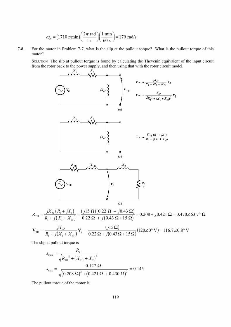
119
( ) 2 rad 1 min1710 r/min 179 rad/s1 r 60 sm
πω = =
7-8. For the motor in Problem 7-7, what is the slip at the pullout torque? What is the pullout torque of this motor?
SOLUTION The slip at pullout torque is found by calculating the Thevenin equivalent of the input circuit from the rotor back to the power supply, and then using that with the rotor circuit model.
( )( )
( ) ( )( )
1 1TH
1 1
15 0.22 0.43 0.208 0.421 0.470 63.7
0.22 0.43 15 M
M
jX R jX j jZ j
R j X X j+ Ω Ω + Ω
= = = + Ω = ∠ ° Ω+ + Ω + Ω + Ω
( )( )
( ) ( ) V 8.07.116V 0120 15 0.43 0.22
15
11TH °∠=°∠
Ω+Ω+ΩΩ=
++=
jj
XXjRjX
M
MφVV
The slip at pullout torque is
( )
2max 22
TH TH 2
RsR X X
=+ +
( ) ( )
max 2 2
0.127 0.1450.208 0.421 0.430
s Ω= =Ω + Ω + Ω
The pullout torque of the motor is
120
( )
2TH
max 22sync TH TH TH 2
3V
R R X Xτ
ω=
2 + + +
( )
( ) ( ) ( )
2
max 2 2
3 116.7 V
88.5 rad/s 0.208 0.208 0.421 0.430 τ =
2 1 Ω + Ω + Ω + Ω
mN 100max ⋅=τ
7-9. (a) Calculate and plot the torque-speed characteristic of the motor in Problem 7-7. (b) Calculate and plot the output power versus speed curve of the motor in Problem 7-7.
SOLUTION
(a) A MATLAB program to calculate the torque-speed characteristic is shown below.
% M-file: prob7_9a.m% M-file create a plot of the torque-speed curve of the% induction motor of Problem 7-7.
% First, initialize the values needed in this program.r1 = 0.220; % Stator resistancex1 = 0.430; % Stator reactancer2 = 0.127; % Rotor resistancex2 = 0.430; % Rotor reactancexm = 15.0; % Magnetization branch reactancev_phase = 208 / sqrt(3); % Phase voltagen_sync = 1800; % Synchronous speed (r/min)w_sync = 188.5; % Synchronous speed (rad/s)
% Calculate the Thevenin voltage and impedance from Equations% 7-38 and 7-41.v_th = v_phase * ( xm / sqrt(r1^2 + (x1 + xm)^2) );z_th = ((j*xm) * (r1 + j*x1)) / (r1 + j*(x1 + xm));r_th = real(z_th);x_th = imag(z_th);
% Now calculate the torque-speed characteristic for many% slips between 0 and 1. Note that the first slip value% is set to 0.001 instead of exactly 0 to avoid divide-% by-zero problems.s = (0:1:50) / 50; % Slips(1) = 0.001;nm = (1 - s) * n_sync; % Mechanical speed
% Calculate torque versus speedfor ii = 1:51
t_ind(ii) = (3 * v_th^2 * r2 / s(ii)) / ...(w_sync * ((r_th + r2/s(ii))^2 + (x_th + x2)^2) );
end
% Plot the torque-speed curvefigure(1);plot(nm,t_ind,'k-','LineWidth',2.0);xlabel('\bf\itn_m');ylabel('\bf\tau_ind');
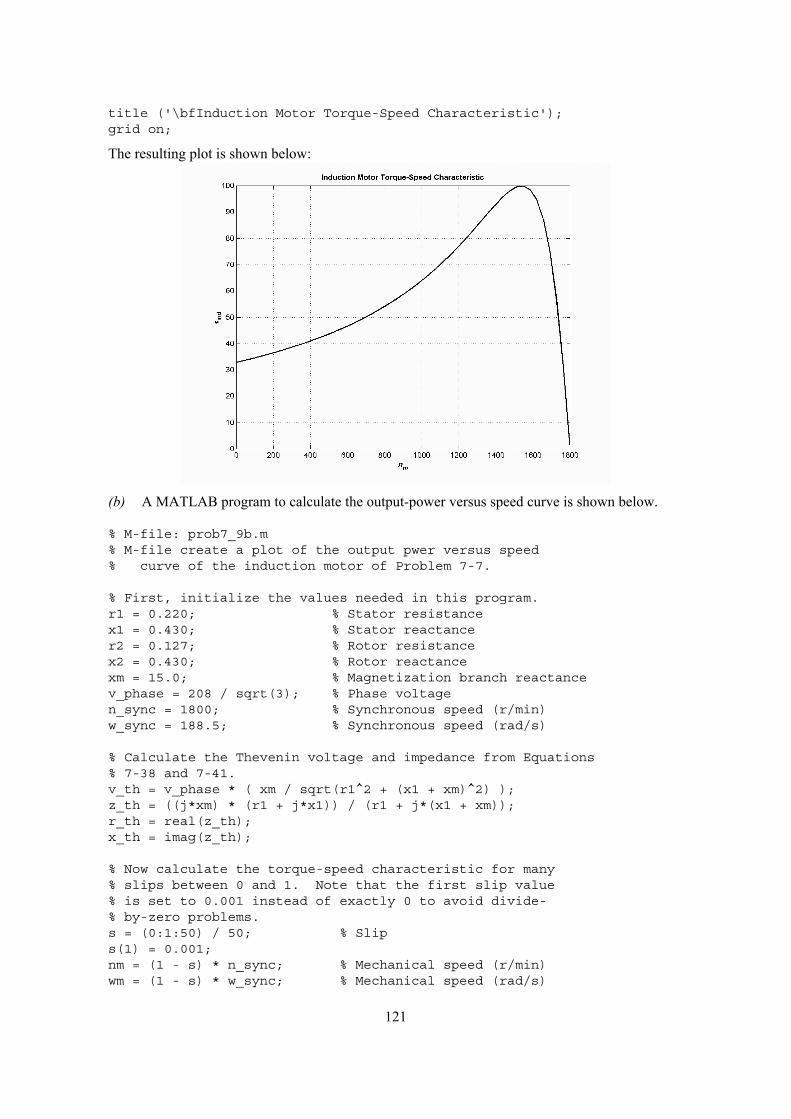
121
title ('\bfInduction Motor Torque-Speed Characteristic');grid on;
The resulting plot is shown below:
(b) A MATLAB program to calculate the output-power versus speed curve is shown below.
% M-file: prob7_9b.m% M-file create a plot of the output pwer versus speed% curve of the induction motor of Problem 7-7.
% First, initialize the values needed in this program.r1 = 0.220; % Stator resistancex1 = 0.430; % Stator reactancer2 = 0.127; % Rotor resistancex2 = 0.430; % Rotor reactancexm = 15.0; % Magnetization branch reactancev_phase = 208 / sqrt(3); % Phase voltagen_sync = 1800; % Synchronous speed (r/min)w_sync = 188.5; % Synchronous speed (rad/s)
% Calculate the Thevenin voltage and impedance from Equations% 7-38 and 7-41.v_th = v_phase * ( xm / sqrt(r1^2 + (x1 + xm)^2) );z_th = ((j*xm) * (r1 + j*x1)) / (r1 + j*(x1 + xm));r_th = real(z_th);x_th = imag(z_th);
% Now calculate the torque-speed characteristic for many% slips between 0 and 1. Note that the first slip value% is set to 0.001 instead of exactly 0 to avoid divide-% by-zero problems.s = (0:1:50) / 50; % Slips(1) = 0.001;nm = (1 - s) * n_sync; % Mechanical speed (r/min)wm = (1 - s) * w_sync; % Mechanical speed (rad/s)
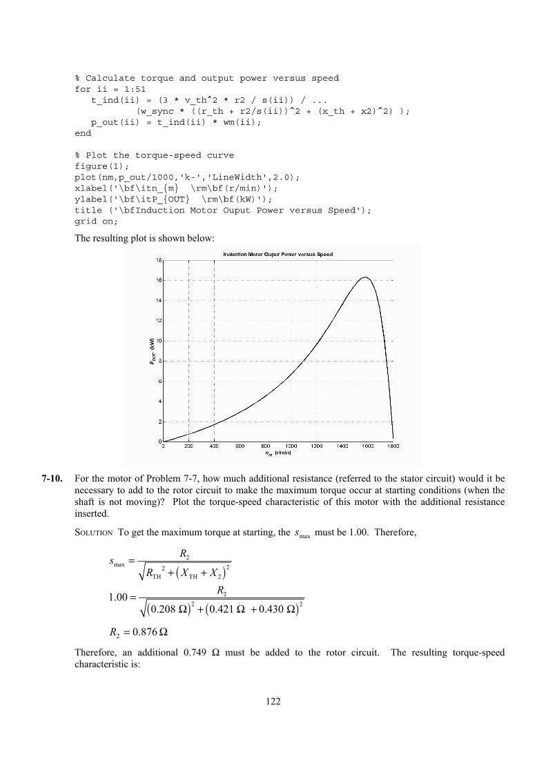
122
% Calculate torque and output power versus speedfor ii = 1:51
t_ind(ii) = (3 * v_th^2 * r2 / s(ii)) / ...(w_sync * ((r_th + r2/s(ii))^2 + (x_th + x2)^2) );
p_out(ii) = t_ind(ii) * wm(ii);end
% Plot the torque-speed curvefigure(1);plot(nm,p_out/1000,'k-','LineWidth',2.0);xlabel('\bf\itn_m \rm\bf(r/min)');ylabel('\bf\itP_OUT \rm\bf(kW)');title ('\bfInduction Motor Ouput Power versus Speed');grid on;
The resulting plot is shown below:
7-10. For the motor of Problem 7-7, how much additional resistance (referred to the stator circuit) would it be
necessary to add to the rotor circuit to make the maximum torque occur at starting conditions (when the shaft is not moving)? Plot the torque-speed characteristic of this motor with the additional resistance inserted.
SOLUTION To get the maximum torque at starting, the maxs must be 1.00. Therefore,
( )
2max 22
TH TH 2
RsR X X
=+ +
( ) ( )
22 2
1.000.208 0.421 0.430
R=Ω + Ω + Ω
Ω= 876.02R
Therefore, an additional 0.749 Ω must be added to the rotor circuit. The resulting torque-speed characteristic is:
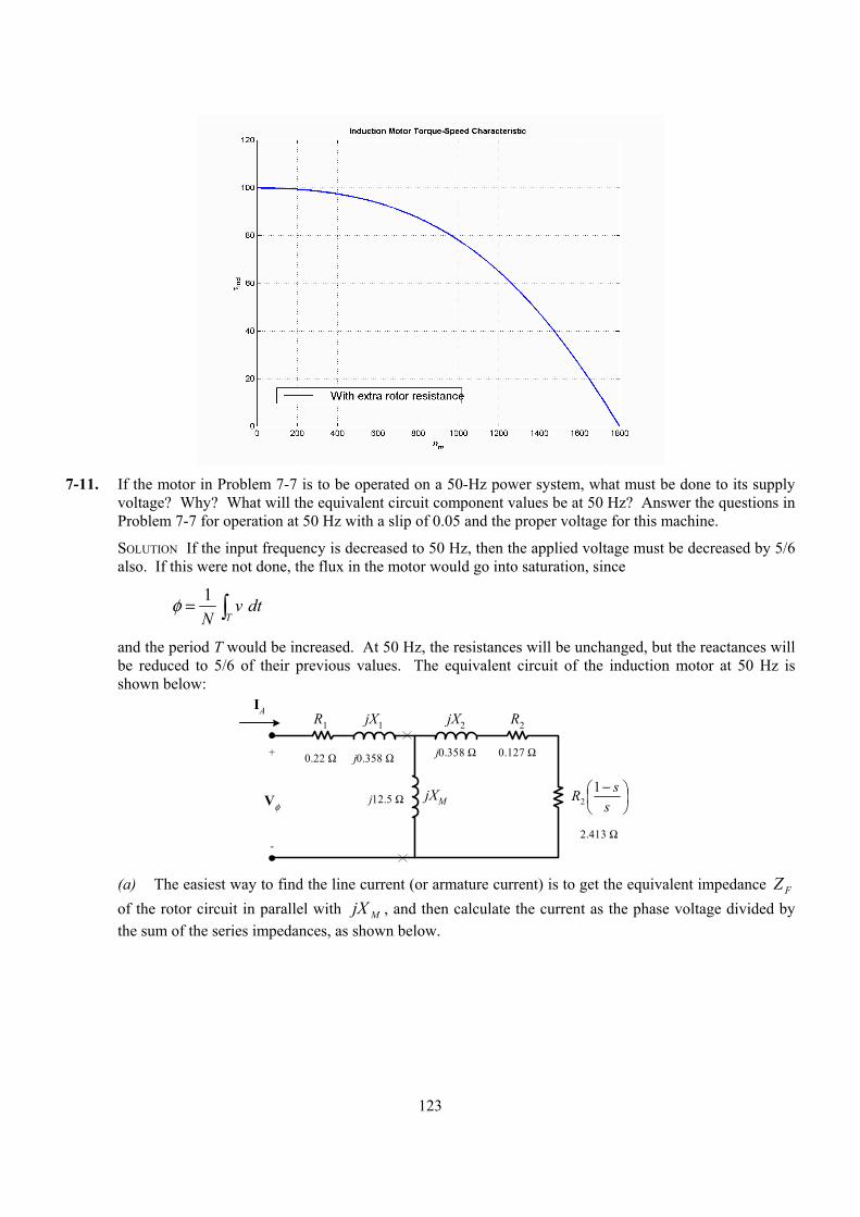
123
7-11. If the motor in Problem 7-7 is to be operated on a 50-Hz power system, what must be done to its supply
voltage? Why? What will the equivalent circuit component values be at 50 Hz? Answer the questions in Problem 7-7 for operation at 50 Hz with a slip of 0.05 and the proper voltage for this machine.
SOLUTION If the input frequency is decreased to 50 Hz, then the applied voltage must be decreased by 5/6 also. If this were not done, the flux in the motor would go into saturation, since
1
Tv dt
Nφ = ∫
and the period T would be increased. At 50 Hz, the resistances will be unchanged, but the reactances will be reduced to 5/6 of their previous values. The equivalent circuit of the induction motor at 50 Hz is shown below:
0.22 Ω j0.358 Ω+
-
Vφ
IAR1 jX1 R2
−
ssR 1
2
jX2
jXM
0.127 Ωj0.358 Ω
j12.5 Ω
2.413 Ω
(a) The easiest way to find the line current (or armature current) is to get the equivalent impedance FZ
of the rotor circuit in parallel with MjX , and then calculate the current as the phase voltage divided by the sum of the series impedances, as shown below.
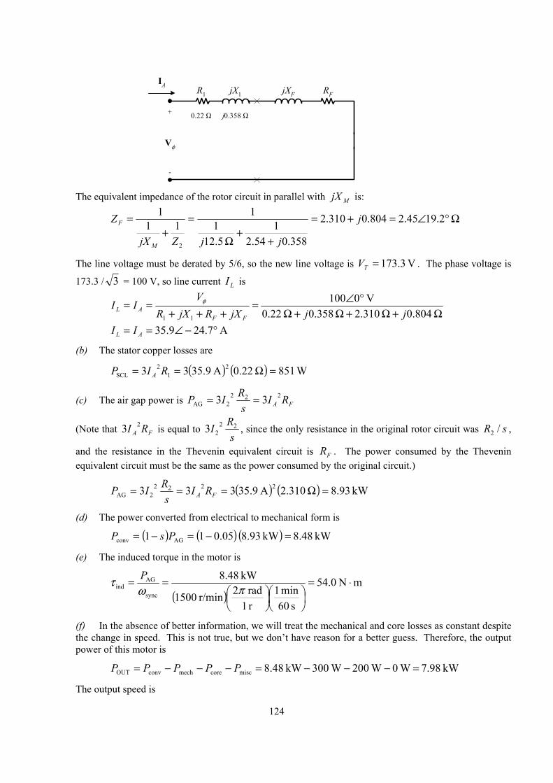
124
0.22 Ω j0.358 Ω+
-
Vφ
IAR1 jX1 RFjXF
The equivalent impedance of the rotor circuit in parallel with MjX is:
Ω°∠=+=
++
Ω
=+
= 2.1945.2804.0310.2
358.054.21
5.121
111
1
2
j
jjZjX
Z
M
F
The line voltage must be derated by 5/6, so the new line voltage is V 3.173=TV . The phase voltage is
173.3 / 3 = 100 V, so line current LI is
Ω+Ω+Ω+Ω
°∠=+++
== 0.804 2.310 0.358 0.22
V 0100
11 jjjXRjXRV
IIFF
ALφ
A 7.249.35 °−∠== AL II
(b) The stator copper losses are
( ) ( ) W 851 22.0A 5.9333 21
2SCL =Ω== RIP A
(c) The air gap power is FA RIs
RIP 2222AG 33 ==
(Note that FA RI 23 is equal to s
RI 2223 , since the only resistance in the original rotor circuit was sR /2 ,
and the resistance in the Thevenin equivalent circuit is FR . The power consumed by the Thevenin equivalent circuit must be the same as the power consumed by the original circuit.)
( ) ( ) kW 93.8 .3102A 5.93333 22222AG =Ω=== FA RI
sRIP
(d) The power converted from electrical to mechanical form is
( ) ( ) ( ) kW 48.8kW 93.8 05.011 AGconv =−=−= PsP
(e) The induced torque in the motor is
( )
mN 0.54
s 60min 1
r 1rad 2r/min 1500
kW 8.48
sync
AGind ⋅=
==πω
τ P
(f) In the absence of better information, we will treat the mechanical and core losses as constant despite the change in speed. This is not true, but we don’t have reason for a better guess. Therefore, the output power of this motor is
kW 7.98 W 0 W 200 W 003kW 48.8misccoremechconvOUT =−−−=−−−= PPPPP
The output speed is
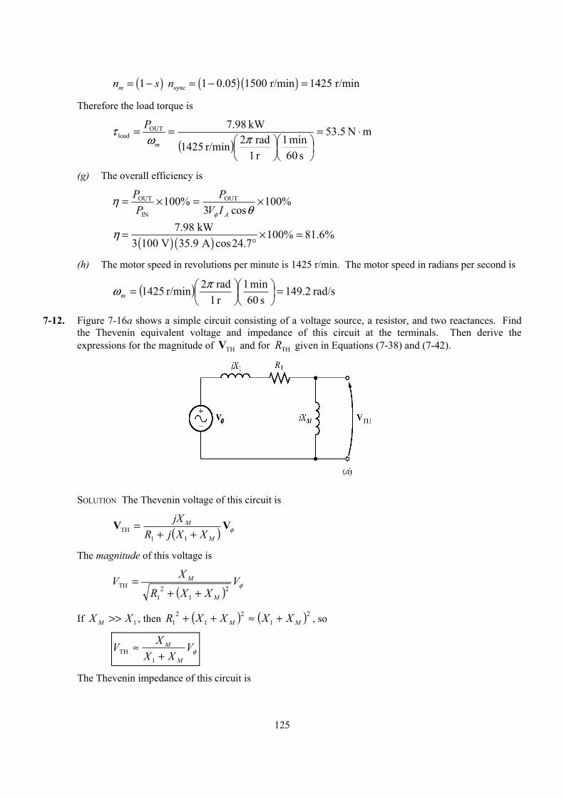
125
( ) ( ) ( )sync1 1 0.05 1500 r/min 1425 r/minmn s n= − = − =
Therefore the load torque is
( )
mN 5.53
s 60min 1
r 1rad 2r/min 1425
kW .987OUTload ⋅=
==πω
τm
P
(g) The overall efficiency is
%100cos3
%100 OUT
IN
OUT ×=×=θ
ηφ AIVP
PP
( ) ( )7.98 kW 100% 81.6%
3 100 V 35.9 A cos24.7η = × =
°
(h) The motor speed in revolutions per minute is 1425 r/min. The motor speed in radians per second is
( ) rad/s 2.149s 60
min 1r 1rad 2r/min 1425 =
= πωm
7-12. Figure 7-16a shows a simple circuit consisting of a voltage source, a resistor, and two reactances. Find the Thevenin equivalent voltage and impedance of this circuit at the terminals. Then derive the expressions for the magnitude of VTH and for RTH given in Equations (7-38) and (7-42).
SOLUTION The Thevenin voltage of this circuit is
( ) φVVM
M
XXjRjX
++=
11TH
The magnitude of this voltage is
( ) φV
XXR
XVM
M2
12
1
TH++
=
If 1XX M >> , then ( ) ( )21
21
21 MM XXXXR +≈++ , so
φVXX
XVM
M
+≈
1TH
The Thevenin impedance of this circuit is
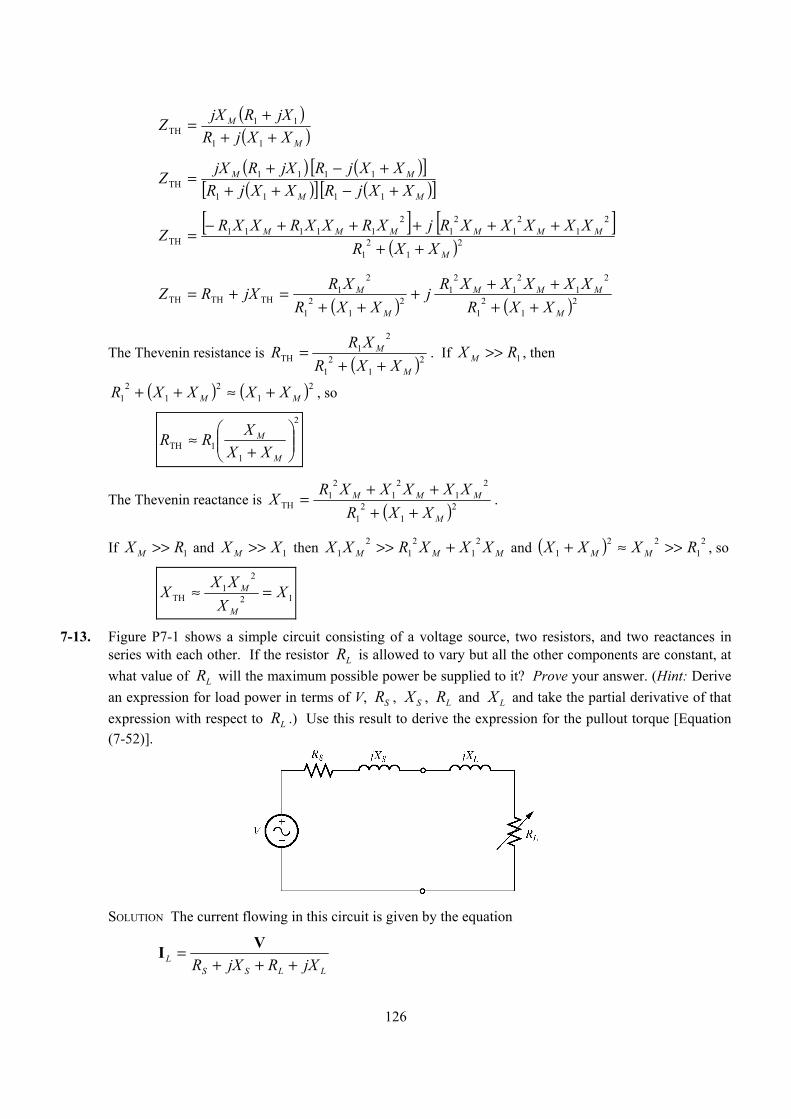
126
( )( )M
M
XXjRjXRjXZ
+++=
11
11TH
( ) ( )[ ]( )[ ] ( )[ ]MM
MM
XXjRXXjRXXjRjXRjXZ
+−+++−+=1111
1111TH
[ ] [ ]
( )21
21
21
21
21
211111
TH
M
MMMMMM
XXRXXXXXRjXRXXRXXRZ
+++++++−=
( ) ( )21
21
21
21
21
21
21
21
THTHTH
M
MMM
M
M
XXRXXXXXRj
XXRXRjXRZ
+++++
++=+=
The Thevenin resistance is ( )21
21
21
THM
M
XXRXRR
++= . If 1RX M >> , then
( ) ( )21
21
21 MM XXXXR +≈++ , so
2
11TH
+
≈M
M
XXXRR
The Thevenin reactance is ( )21
21
21
21
21
TH
M
MMM
XXRXXXXXRX
++++= .
If 1RX M >> and 1XX M >> then MMM XXXRXX 21
21
21 +>> and ( ) 2
122
1 RXXX MM >>≈+ , so
12
21
TH X
XXXXM
M =≈
7-13. Figure P7-1 shows a simple circuit consisting of a voltage source, two resistors, and two reactances in series with each other. If the resistor RL is allowed to vary but all the other components are constant, at what value of RL will the maximum possible power be supplied to it? Prove your answer. (Hint: Derive an expression for load power in terms of V, RS , X S , RL and X L and take the partial derivative of that expression with respect to RL .) Use this result to derive the expression for the pullout torque [Equation (7-52)].
SOLUTION The current flowing in this circuit is given by the equation
LLSS
L jXRjXR +++= VI
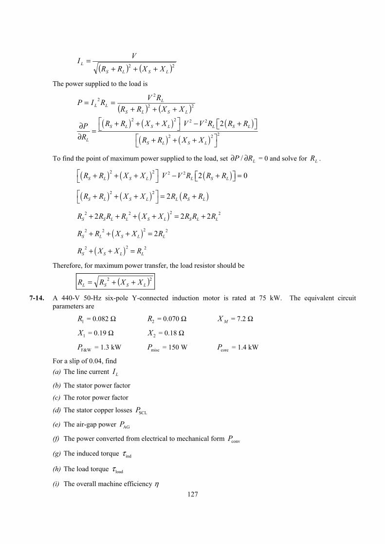
127
( ) ( )22
LSLS
LXXRR
VI+++
=
The power supplied to the load is
( ) ( )22
22
LSLS
LLL XXRR
RVRIP+++
==
( ) ( ) ( )
( ) ( )
2 2 2 2
22 2
2S L S L L S L
LS L S L
R R X X V V R R RPR R R X X
+ + + − +∂ =∂ + + +
To find the point of maximum power supplied to the load, set LRP ∂∂ / = 0 and solve for LR .
( ) ( ) ( )2 2 2 2 2 0S L S L L S LR R X X V V R R R + + + − + =
( ) ( ) ( )2 2 2S L S L L S LR R X X R R R + + + = +
( )22 2 22 2 2S S L L S L S L LR R R R X X R R R+ + + + = +
( )22 2 22S L S L LR R X X R+ + + =
( )22 2S S L LR X X R+ + =
Therefore, for maximum power transfer, the load resistor should be
( )22LSSL XXRR ++=
7-14. A 440-V 50-Hz six-pole Y-connected induction motor is rated at 75 kW. The equivalent circuit parameters are
R1 = 0.082 Ω R2 = 0.070 Ω X M = 7.2 Ω
X1 = 0.19 Ω X 2 = 0.18 Ω
PF&W = 1.3 kW Pmisc = 150 W Pcore = 1.4 kW
For a slip of 0.04, find (a) The line current IL
(b) The stator power factor
(c) The rotor power factor
(d) The stator copper losses PSCL
(e) The air-gap power PAG
(f) The power converted from electrical to mechanical form Pconv
(g) The induced torque indτ
(h) The load torque loadτ
(i) The overall machine efficiency η
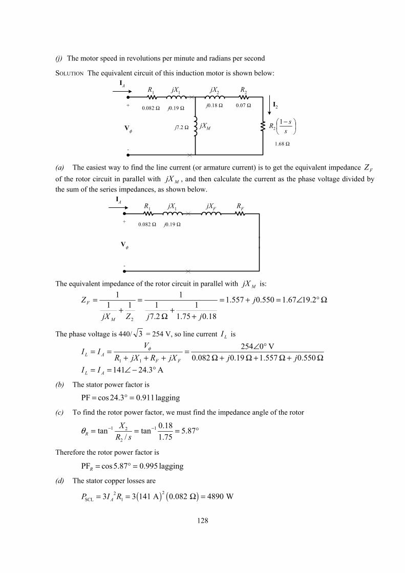
128
(j) The motor speed in revolutions per minute and radians per second
SOLUTION The equivalent circuit of this induction motor is shown below:
0.082 Ω j0.19 Ω+
-
Vφ
IAR1 jX1 R2
−
ssR 1
2
jX2
jXM
0.07 Ωj0.18 Ω
j7.2 Ω
1.68 Ω
I2
(a) The easiest way to find the line current (or armature current) is to get the equivalent impedance FZ
of the rotor circuit in parallel with MjX , and then calculate the current as the phase voltage divided by the sum of the series impedances, as shown below.
0.082 Ω j0.19 Ω+
-
Vφ
IAR1 jX1 RFjXF
The equivalent impedance of the rotor circuit in parallel with MjX is:
Ω°∠=+=
++
Ω
=+
= 2.1967.1550.0557.1
18.075.11
2.71
111
1
2
j
jjZjX
Z
M
F
The phase voltage is 440/ 3 = 254 V, so line current LI is
Ω+Ω+Ω+Ω
°∠=+++
== 0.550 1.557 0.19 0.082
V 0254
11 jjjXRjXRV
IIFF
ALφ
A 3.24141 °−∠== AL II
(b) The stator power factor is
lagging 911.03.24cos PF =°=
(c) To find the rotor power factor, we must find the impedance angle of the rotor
1 12
2
0.18tan tan 5.87/ 1.75R
XR s
θ − −= = = °
Therefore the rotor power factor is
lagging 995.087.5cos PF =°=R
(d) The stator copper losses are
( ) ( )22SCL 13 3 141 A 0.082 4890 WAP I R= = Ω =
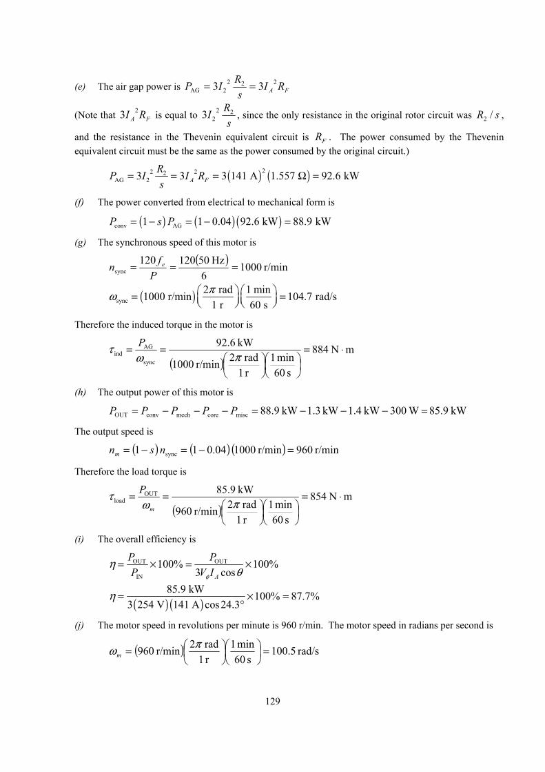
129
(e) The air gap power is FA RIs
RIP 2222AG 33 ==
(Note that FA RI 23 is equal to s
RI 2223 , since the only resistance in the original rotor circuit was sR /2 ,
and the resistance in the Thevenin equivalent circuit is FR . The power consumed by the Thevenin equivalent circuit must be the same as the power consumed by the original circuit.)
( ) ( )22 22AG 23 3 3 141 A 1.557 92.6 kWA F
RP I I Rs
= = = Ω =
(f) The power converted from electrical to mechanical form is
( ) ( ) ( )conv AG1 1 0.04 92.6 kW 88.9 kWP s P= − = − =
(g) The synchronous speed of this motor is
( ) r/min 1000
6 Hz50120120
sync ===P
fn e
( )sync2 rad 1 min1000 r/min 104.7 rad/s
1 r 60 sπω = =
Therefore the induced torque in the motor is
( )
mN 884
s 60min 1
r 1rad 2r/min 1000
kW 92.6
sync
AGind ⋅=
==πω
τ P
(h) The output power of this motor is
kW 85.9 W 300 kW 1.4 kW 3.1kW 9.88misccoremechconvOUT =−−−=−−−= PPPPP
The output speed is
( ) ( ) ( ) r/min 960r/min 0100 04.01 1 sync =−=−= nsnm
Therefore the load torque is
( )
mN 854
s 60min 1
r 1rad 2r/min 960
kW 5.98OUTload ⋅=
==πω
τm
P
(i) The overall efficiency is
OUT OUT
IN
100% 100%3 cosA
P PP V Iφ
ηθ
= × = ×
( ) ( )85.9 kW 100% 87.7%
3 254 V 141 A cos24.3η = × =
°
(j) The motor speed in revolutions per minute is 960 r/min. The motor speed in radians per second is
( ) rad/s 5.100s 60
min 1r 1rad 2r/min 960 =
= πωm
130
7-15. For the motor in Problem 7-14, what is the pullout torque? What is the slip at the pullout torque? What is the rotor speed at the pullout torque?
SOLUTION The slip at pullout torque is found by calculating the Thevenin equivalent of the input circuit from the rotor back to the power supply, and then using that with the rotor circuit model.
( )( )
( )( )( ) Ω°∠=Ω+=
Ω+Ω+ΩΩ+ΩΩ=
+++= 3.67202.0 1860.00778.0
2.7 0.19 0.082 0.19 082.0 2.7
11
11TH j
jjj
XXjRjXRjXZ
M
M
( )( )
( ) ( ) V 6.05.247V 0254 2.7 0.19 0.082
2.7
11TH °∠=°∠
Ω+Ω+ΩΩ=
++=
jj
XXjRjX
M
MφVV
The slip at pullout torque is
( )2
2TH2
TH
2max
XXR
Rs++
=
( ) ( )
187.0 180.0 186.0 0778.0
070.022max =
Ω+Ω+Ω
Ω=s
The pullout torque of the motor is
( )
+++2
=2
2TH2THTHsync
2TH
max3
XXRR
V
ωτ
( )
( ) ( ) ( )
Ω+Ω+Ω+Ω2
=22
2
max 180.0 186.0 0778.0 0778.0rad/s 7.401
V 47.523τ
mN 1941max ⋅=τ
7-16. If the motor in Problem 7-14 is to be driven from a 440-V 60-Hz power supply, what will the pullout torque be? What will the slip be at pullout?
SOLUTION If this motor is driven from a 60 Hz source, the resistances will be unchanged and the reactances will be increased by a ratio of 6/5. The resulting equivalent circuit is shown below.
0.082 Ω j0.228 Ω+
-
Vφ
IAR1 jX1 R2
−
ssR 1
2
jX2
jXM
0.07 Ωj0.216 Ω
j8.64 Ω
1.68 Ω
I2
The slip at pullout torque is found by calculating the Thevenin equivalent of the input circuit from the
rotor back to the power supply, and then using that with the rotor circuit model.
( )( )
( ) ( )( )
1 1TH
1 1
8.64 0.082 0.228 0.0778 0.223 0.236 70.7
0.082 0.228 8.64 M
M
jX R jX j jZ j
R j X X j+ Ω Ω + Ω
= = = + Ω = ∠ ° Ω+ + Ω + Ω + Ω
( ) ( ) ( )TH1 1
8.64 254 0 V 247.5 0.5 V0.082 0.228 8.64
M
M
jX jR j X X jφ
Ω= = ∠ ° = ∠ °+ + Ω + Ω + Ω
V V
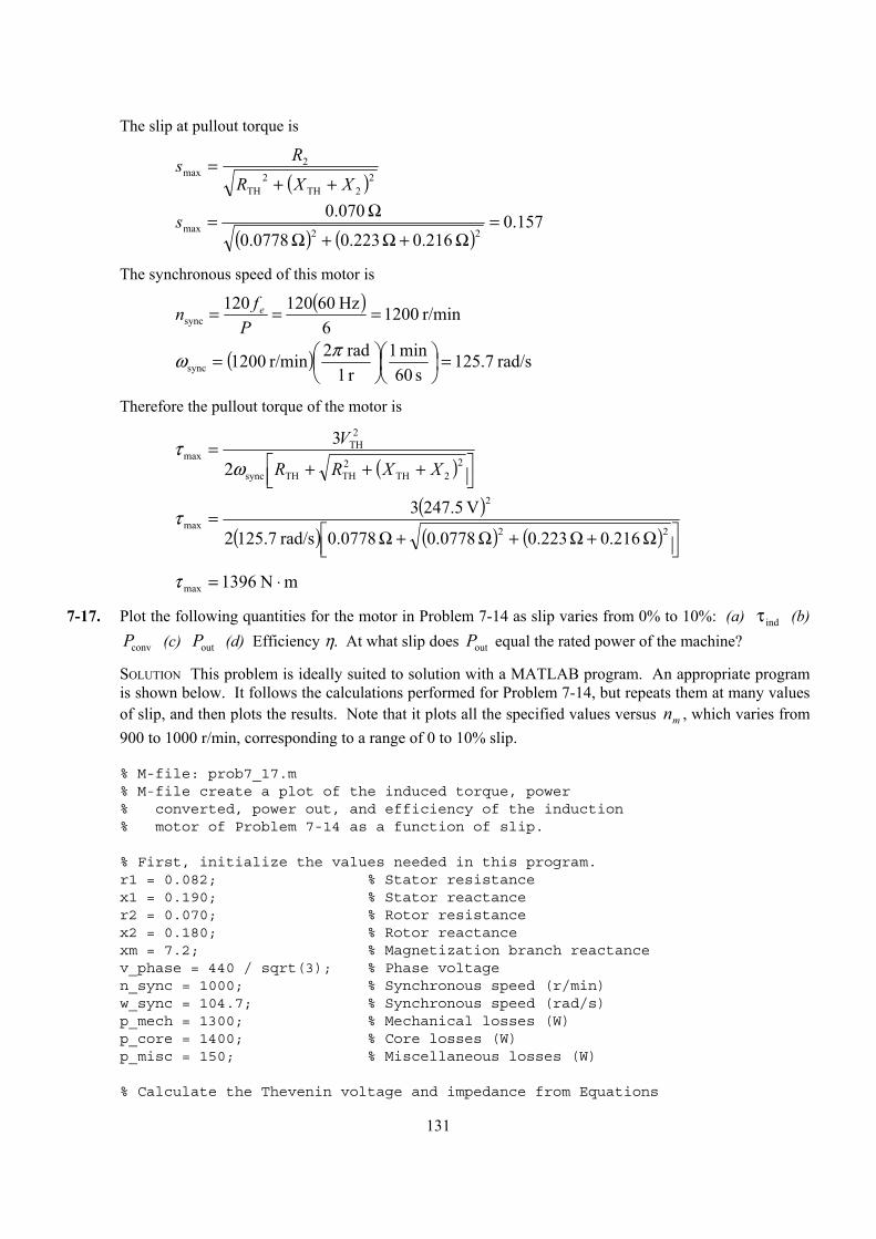
131
The slip at pullout torque is
( )2
2TH2
TH
2max
XXR
Rs++
=
( ) ( )
157.0 216.0 223.0 0778.0
070.022max =
Ω+Ω+Ω
Ω=s
The synchronous speed of this motor is
( ) r/min 1200
6 Hz60120120
sync ===P
fn e
( ) rad/s 7.125s 60
min 1r 1rad 2r/min 1200sync =
= πω
Therefore the pullout torque of the motor is
( )
+++2
=2
2TH2THTHsync
2TH
max3
XXRR
V
ωτ
( )
( ) ( ) ( )
Ω+Ω+Ω+Ω2
=22
2
max 216.0 223.0 0778.0 0778.0rad/s 7.521
V 47.523τ
mN 1396max ⋅=τ
7-17. Plot the following quantities for the motor in Problem 7-14 as slip varies from 0% to 10%: (a) τ ind (b) Pconv (c) outP (d) Efficiency η. At what slip does outP equal the rated power of the machine?
SOLUTION This problem is ideally suited to solution with a MATLAB program. An appropriate program is shown below. It follows the calculations performed for Problem 7-14, but repeats them at many values of slip, and then plots the results. Note that it plots all the specified values versus mn , which varies from 900 to 1000 r/min, corresponding to a range of 0 to 10% slip.
% M-file: prob7_17.m% M-file create a plot of the induced torque, power% converted, power out, and efficiency of the induction% motor of Problem 7-14 as a function of slip.
% First, initialize the values needed in this program.r1 = 0.082; % Stator resistancex1 = 0.190; % Stator reactancer2 = 0.070; % Rotor resistancex2 = 0.180; % Rotor reactancexm = 7.2; % Magnetization branch reactancev_phase = 440 / sqrt(3); % Phase voltagen_sync = 1000; % Synchronous speed (r/min)w_sync = 104.7; % Synchronous speed (rad/s)p_mech = 1300; % Mechanical losses (W)p_core = 1400; % Core losses (W)p_misc = 150; % Miscellaneous losses (W)
% Calculate the Thevenin voltage and impedance from Equations

132
% 7-38 and 7-41.v_th = v_phase * ( xm / sqrt(r1^2 + (x1 + xm)^2) );z_th = ((j*xm) * (r1 + j*x1)) / (r1 + j*(x1 + xm));r_th = real(z_th);x_th = imag(z_th);
% Now calculate the torque-speed characteristic for many% slips between 0 and 0.1. Note that the first slip value% is set to 0.001 instead of exactly 0 to avoid divide-% by-zero problems.s = (0:0.001:0.1); % Slips(1) = 0.001;nm = (1 - s) * n_sync; % Mechanical speedwm = nm * 2*pi/60; % Mechanical speed
% Calculate torque, P_conv, P_out, and efficiency% versus speedfor ii = 1:length(s)
% Induced torquet_ind(ii) = (3 * v_th^2 * r2 / s(ii)) / ...
(w_sync * ((r_th + r2/s(ii))^2 + (x_th + x2)^2) );
% Power convertedp_conv(ii) = t_ind(ii) * wm(ii);
% Power outputp_out(ii) = p_conv(ii) - p_mech - p_core - p_misc;
% Power inputzf = 1 / ( 1/(j*xm) + 1/(r2/s(ii)+j*x2) );ia = v_phase / ( r1 + j*x1 + zf );p_in(ii) = 3 * v_phase * abs(ia) * cos(atan(imag(ia)/real(ia)));
% Efficiencyeff(ii) = p_out(ii) / p_in(ii) * 100;
end
% Plot the torque-speed curvefigure(1);plot(nm,t_ind,'b-','LineWidth',2.0);xlabel('\bf\itn_m \rm\bf(r/min)');ylabel('\bf\tau_ind \rm\bf(N-m)');title ('\bfInduced Torque versus Speed');grid on;
% Plot power converted versus speedfigure(2);plot(nm,p_conv/1000,'b-','LineWidth',2.0);xlabel('\bf\itn_m \rm\bf(r/min)');ylabel('\bf\itP\rm\bf_conv (kW)');title ('\bfPower Converted versus Speed');grid on;
% Plot output power versus speed
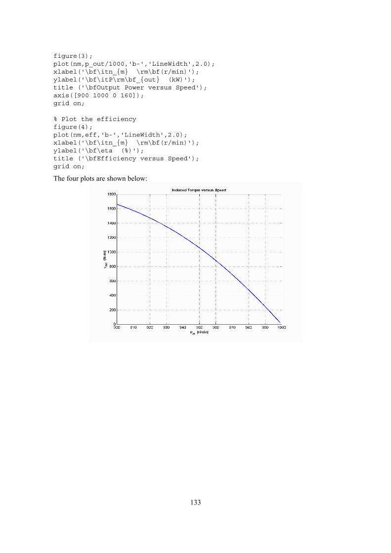
133
figure(3);plot(nm,p_out/1000,'b-','LineWidth',2.0);xlabel('\bf\itn_m \rm\bf(r/min)');ylabel('\bf\itP\rm\bf_out (kW)');title ('\bfOutput Power versus Speed');axis([900 1000 0 160]);grid on;
% Plot the efficiencyfigure(4);plot(nm,eff,'b-','LineWidth',2.0);xlabel('\bf\itn_m \rm\bf(r/min)');ylabel('\bf\eta (%)');title ('\bfEfficiency versus Speed');grid on;
The four plots are shown below:
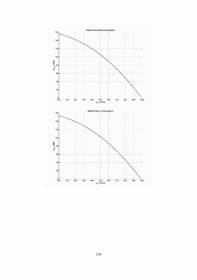
134
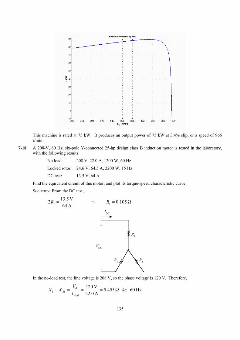
135
This machine is rated at 75 kW. It produces an output power of 75 kW at 3.4% slip, or a speed of 966
r/min.
7-18. A 208-V, 60 Hz, six-pole Y-connected 25-hp design class B induction motor is tested in the laboratory, with the following results:
No load: 208 V, 22.0 A, 1200 W, 60 Hz
Locked rotor: 24.6 V, 64.5 A, 2200 W, 15 Hz
DC test: 13.5 V, 64 A
Find the equivalent circuit of this motor, and plot its torque-speed characteristic curve.
SOLUTION From the DC test,
A 64V 5.132 1 =R ⇒ Ω= 105.01R
R1 R1
R1
VDC
+
-
IDC
In the no-load test, the line voltage is 208 V, so the phase voltage is 120 V. Therefore,
Hz60 @ 455.5A 22.0V 120
nl,1 Ω===+
AM I
VXX φ
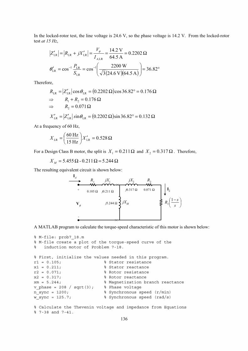
136
In the locked-rotor test, the line voltage is 24.6 V, so the phase voltage is 14.2 V. From the locked-rotor test at 15 Hz,
Ω===′+=′ 2202.0A 64.5V 2.14
LR,LRLRLR
AIV
XjRZ φ
( )( ) °=
==′ −− 82.36
A 5.64V 6.243W 2200coscos 1
LR
LR1LR S
Pθ
Therefore,
( ) Ω=°Ω=′= 176.082.36cos 2202.0cos LRLRLR θZR
⇒ Ω=+ 176.021 RR ⇒ Ω= 071.02R
( ) Ω=°Ω=′=′ 132.082.36sin 2202.0in LRLRLR θsZX
At a frequency of 60 Hz,
Ω=′
= 528.0
Hz15 Hz60
LRLR XX
For a Design Class B motor, the split is Ω= 211.01X and Ω= 317.02X . Therefore,
Ω=ΩΩ= 5.244 0.211- 455.5MX
The resulting equivalent circuit is shown below:
0.105 Ω j0.211 Ω+
-
Vφ
IAR1 jX1 R2
−
ssR 1
2
jX2
jXM
0.071 Ωj0.317 Ω
j5.244 Ω
I2
A MATLAB program to calculate the torque-speed characteristic of this motor is shown below:
% M-file: prob7_18.m% M-file create a plot of the torque-speed curve of the% induction motor of Problem 7-18.
% First, initialize the values needed in this program.r1 = 0.105; % Stator resistancex1 = 0.211; % Stator reactancer2 = 0.071; % Rotor resistancex2 = 0.317; % Rotor reactancexm = 5.244; % Magnetization branch reactancev_phase = 208 / sqrt(3); % Phase voltagen_sync = 1200; % Synchronous speed (r/min)w_sync = 125.7; % Synchronous speed (rad/s)
% Calculate the Thevenin voltage and impedance from Equations% 7-38 and 7-41.
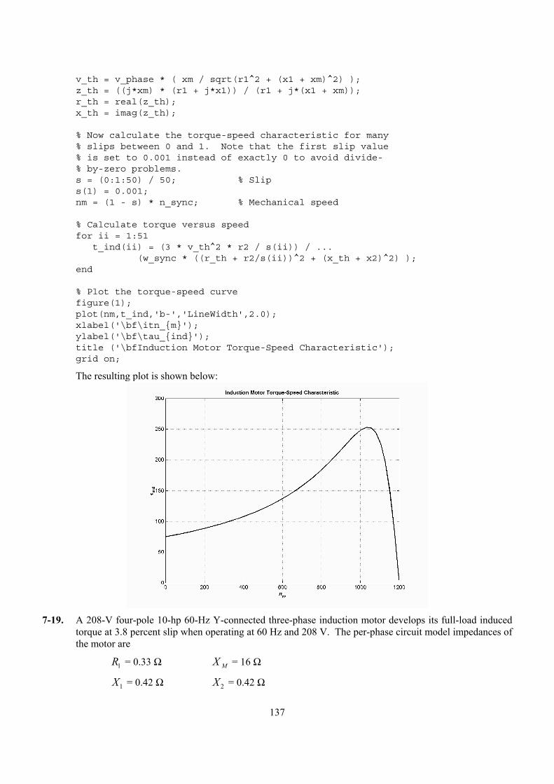
137
v_th = v_phase * ( xm / sqrt(r1^2 + (x1 + xm)^2) );z_th = ((j*xm) * (r1 + j*x1)) / (r1 + j*(x1 + xm));r_th = real(z_th);x_th = imag(z_th);
% Now calculate the torque-speed characteristic for many% slips between 0 and 1. Note that the first slip value% is set to 0.001 instead of exactly 0 to avoid divide-% by-zero problems.s = (0:1:50) / 50; % Slips(1) = 0.001;nm = (1 - s) * n_sync; % Mechanical speed
% Calculate torque versus speedfor ii = 1:51
t_ind(ii) = (3 * v_th^2 * r2 / s(ii)) / ...(w_sync * ((r_th + r2/s(ii))^2 + (x_th + x2)^2) );
end
% Plot the torque-speed curvefigure(1);plot(nm,t_ind,'b-','LineWidth',2.0);xlabel('\bf\itn_m');ylabel('\bf\tau_ind');title ('\bfInduction Motor Torque-Speed Characteristic');grid on;
The resulting plot is shown below:
7-19. A 208-V four-pole 10-hp 60-Hz Y-connected three-phase induction motor develops its full-load induced
torque at 3.8 percent slip when operating at 60 Hz and 208 V. The per-phase circuit model impedances of the motor are
R1 = 0.33 Ω X M = 16 Ω
X1 = 0.42 Ω X 2 = 0.42 Ω
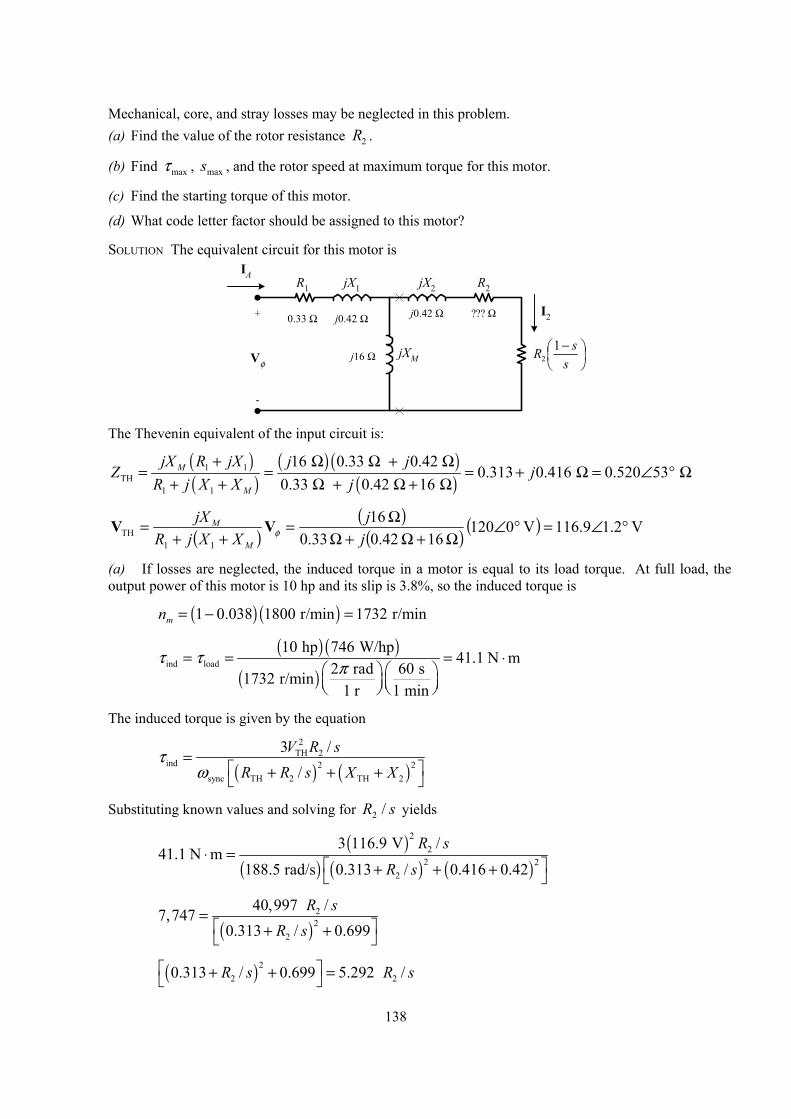
138
Mechanical, core, and stray losses may be neglected in this problem. (a) Find the value of the rotor resistance R2 .
(b) Find maxτ , smax , and the rotor speed at maximum torque for this motor.
(c) Find the starting torque of this motor.
(d) What code letter factor should be assigned to this motor?
SOLUTION The equivalent circuit for this motor is
0.33 Ω j0.42 Ω+
-
Vφ
IAR1 jX1 R2
−
ssR 1
2
jX2
jXM
??? Ωj0.42 Ω
j16 Ω
I2
The Thevenin equivalent of the input circuit is:
( )( )
( ) ( )( )
1 1TH
1 1
16 0.33 0.42 0.313 0.416 0.520 53
0.33 0.42 16 M
M
jX R jX j jZ j
R j X X j+ Ω Ω + Ω
= = = + Ω = ∠ ° Ω+ + Ω + Ω + Ω
( )( )
( ) ( ) V 2.19.116V 0120 16 0.42 0.33
16
11TH °∠=°∠
Ω+Ω+ΩΩ=
++=
jj
XXjRjX
M
MφVV
(a) If losses are neglected, the induced torque in a motor is equal to its load torque. At full load, the output power of this motor is 10 hp and its slip is 3.8%, so the induced torque is
( ) ( )1 0.038 1800 r/min 1732 r/minmn = − =
( ) ( )
( )ind load
10 hp 746 W/hp41.1 N m
2 rad 60 s1732 r/min1 r 1 min
τ τ π= = = ⋅
The induced torque is given by the equation
( ) ( )
2TH 2
ind 2 2sync TH 2 TH 2
3 //
V R sR R s X X
τω
= + + +
Substituting known values and solving for sR /2 yields
( )
( ) ( ) ( )
22
2 22
3 116.9 V /41.1 N m
188.5 rad/s 0.313 / 0.416 0.42
R s
R s⋅ =
+ + +
( )
22
2
40,997 /7,7470.313 / 0.699
R sR s
= + +
( )22 20.313 / 0.699 5.292 /R s R s + + =
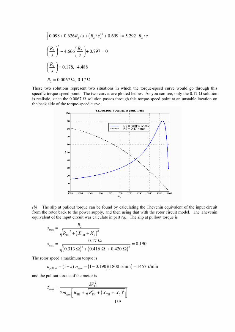
139
( )22 2 20.098 0.626 / / 0.699 5.292 /R s R s R s + + + =
0797.0666.4 22
2 =+
−
sR
sR
488.4 ,178.02 =
sR
ΩΩ= 0.17 , 0067.02R
These two solutions represent two situations in which the torque-speed curve would go through this specific torque-speed point. The two curves are plotted below. As you can see, only the 0.17 Ω solution is realistic, since the 0.0067 Ω solution passes through this torque-speed point at an unstable location on the back side of the torque-speed curve.
(b) The slip at pullout torque can be found by calculating the Thevenin equivalent of the input circuit
from the rotor back to the power supply, and then using that with the rotor circuit model. The Thevenin equivalent of the input circuit was calculate in part (a). The slip at pullout torque is
( )
2max 22
TH TH 2
RsR X X
=+ +
( ) ( )
max 2 2
0.17 0.1900.313 0.416 0.420
s Ω= =Ω + Ω + Ω
The rotor speed a maximum torque is
( ) ( )pullout sync(1 ) 1 0.190 1800 r/min 1457 r/minn s n= − = − =
and the pullout torque of the motor is
( )
+++2
=2
2TH2THTHsync
2TH
max3
XXRR
V
ωτ
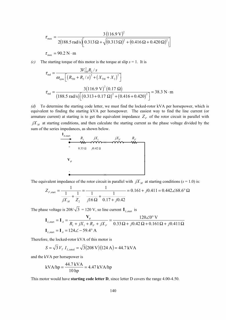
140
( )
( ) ( ) ( )
Ω+Ω+Ω+Ω2
=22
2
max 420.0 416.0 313.0 313.0rad/s 88.51
V 16.91 3τ
mN 2.90max ⋅=τ
(c) The starting torque of this motor is the torque at slip s = 1. It is
( ) ( )
2TH 2
ind 2 2sync TH 2 TH 2
3 //
V R sR R s X X
τω
= + + +
( ) ( )
( ) ( ) ( )
2
ind 2 2
3 116.9 V 0.17 38.3 N m
188.5 rad/s 0.313 0.17 0.416 0.420τ Ω
= = ⋅ + Ω + +
(d) To determine the starting code letter, we must find the locked-rotor kVA per horsepower, which is equivalent to finding the starting kVA per horsepower. The easiest way to find the line current (or armature current) at starting is to get the equivalent impedance FZ of the rotor circuit in parallel with
MjX at starting conditions, and then calculate the starting current as the phase voltage divided by the sum of the series impedances, as shown below.
0.33 Ω j0.42 Ω+
-
Vφ
IA,startR1 jX1 RFjXF
The equivalent impedance of the rotor circuit in parallel with MjX at starting conditions (s = 1.0) is:
Ω°∠=+=
++
Ω
=+
= 6.68442.0411.0161.0
42.017.01
161
111
1
2
start, j
jjZjX
Z
M
F
The phase voltage is 208/ 3 = 120 V, so line current start,LI is
Ω+Ω+Ω+Ω
°∠=+++
== 0.411 0.161 0.42 0.33
V 0120
11start, jjjXRjXR FF
ALφV
II
A 4.59124start, °−∠== AL II
Therefore, the locked-rotor kVA of this motor is
( ) ( ) kVA 7.44A 124 V 2083 3 rated, === LT IVS
and the kVA per horsepower is
kVA/hp 47.4hp 10kVA 44.7kVA/hp ==
This motor would have starting code letter D, since letter D covers the range 4.00-4.50.
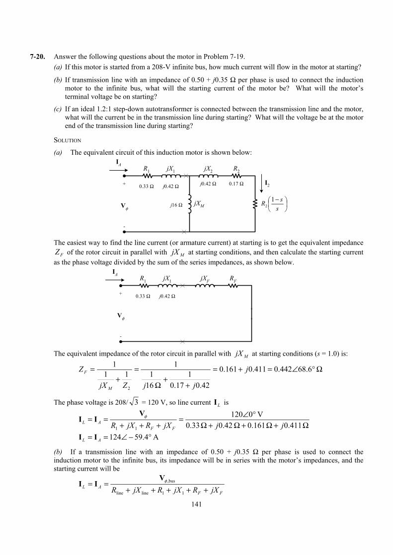
141
7-20. Answer the following questions about the motor in Problem 7-19. (a) If this motor is started from a 208-V infinite bus, how much current will flow in the motor at starting?
(b) If transmission line with an impedance of 0.50 + j0.35 Ω per phase is used to connect the induction motor to the infinite bus, what will the starting current of the motor be? What will the motor’s terminal voltage be on starting?
(c) If an ideal 1.2:1 step-down autotransformer is connected between the transmission line and the motor, what will the current be in the transmission line during starting? What will the voltage be at the motor end of the transmission line during starting?
SOLUTION
(a) The equivalent circuit of this induction motor is shown below:
0.33 Ω j0.42 Ω+
-
Vφ
IAR1 jX1 R2
−
ssR 1
2
jX2
jXM
0.17 Ωj0.42 Ω
j16 Ω
I2
The easiest way to find the line current (or armature current) at starting is to get the equivalent impedance
FZ of the rotor circuit in parallel with MjX at starting conditions, and then calculate the starting current as the phase voltage divided by the sum of the series impedances, as shown below.
0.33 Ω j0.42 Ω+
-
Vφ
IAR1 jX1 RFjXF
The equivalent impedance of the rotor circuit in parallel with MjX at starting conditions (s = 1.0) is:
Ω°∠=+=
++
Ω
=+
= 6.68442.0411.0161.0
42.017.01
161
111
1
2
j
jjZjX
Z
M
F
The phase voltage is 208/ 3 = 120 V, so line current LI is
Ω+Ω+Ω+Ω
°∠=+++
== 0.411 0.161 0.42 0.33
V 0120
11 jjjXRjXR FFAL
φVII
A 4.59124 °−∠== AL II
(b) If a transmission line with an impedance of 0.50 + j0.35 Ω per phase is used to connect the induction motor to the infinite bus, its impedance will be in series with the motor’s impedances, and the starting current will be
FF
AL jXRjXRjXR +++++==
11lineline
bus,φVII
142
120 0 V
0.50 0.35 0.33 0.42 0.161 0.411 L A j j j∠ °= =
Ω + Ω + Ω + Ω + Ω + ΩI I
77.8 50.0 AL A= = ∠ − °I I
The voltage at the terminals of the motor will be
( )FFA jXRjXR +++= 11IVφ
( ) ( )77.8 50.0 A 0.33 0.42 0.161 0.411 j jφ = ∠ − ° Ω + Ω + Ω + ΩV
75.1 9.4 Vφ = ∠ °V
Therefore, the terminal voltage will be ( )3 75.1 V 130 V= . Note that the terminal voltage sagged by 37.5% during motor starting, which would be unacceptable.
(c) If an ideal 1.2:1 step-down autotransformer is connected between the transmission line and the motor, the motor’s impedances will be referred across the transformer by the square of the turns ratio a = 1.2. The referred impedances are
( )21 1 1.44 0.33 0.475 R a R= = Ω = Ω′
( )21 1 1.44 0.42 0.605 X a X= = Ω = Ω′
( )2 1.44 0.161 0.232 F FR a R= = Ω = Ω′
( )2 1.44 0.411 0.592 F FX a X= = Ω = Ω′
Therefore, the starting current referred to the primary side of the transformer will be
FF
AL XjRXjRjXR ′+′+′+′++=′=′
11lineline
bus,φVII
120 0 V
0.50 0.35 0.475 0.605 0.232 0.592 L A j j j∠ °= =′ ′
Ω + Ω + Ω + Ω + Ω + ΩI I
61.2 52 AL A= = ∠ − °′ ′I I
The voltage at the motor end of the transmission line would be the same as the referred voltage at the terminals of the motor
( )FFA XjRXjR ′+′+′+′′=′ 11IVφ
( ) ( )61.2 52 A 0.475 0.605 0.232 0.592 j jφ = ∠ − ° Ω + Ω + Ω + ΩV
85.0 7.4 Vφ = ∠ °V
Therefore, the line voltage at the motor end of the transmission line will be ( )3 85 V 147.3 V= . Note that this voltage sagged by 29.2% during motor starting, which is less than the 37.5% sag with case of across-the-line starting. Since the sag is still large, it might be possible to use a bigger autotransformer turns ratio on the starter.
7-21. In this chapter, we learned that a step-down autotransformer could be used to reduce the starting current drawn by an induction motor. While this technique works, an autotransformer is relatively expensive. A much less expensive way to reduce the starting current is to use a device called Y-∆ starter. If an induction motor is normally ∆-connected, it is possible to reduce its phase voltage Vφ (and hence its starting current) by simply re-connecting the stator windings in Y during starting, and then restoring the connections to ∆ when the motor comes up to speed. Answer the following questions about this type of starter.
143
(a) How would the phase voltage at starting compare with the phase voltage under normal running conditions?
(b) How would the starting current of the Y-connected motor compare to the starting current if the motor remained in a ∆-connection during starting?
SOLUTION
(a) The phase voltage at starting would be 1 / 3 = 57.7% of the phase voltage under normal running conditions.
(b) Since the phase voltage decreases to 1 / 3 = 57.7% of the normal voltage, the starting phase current will also decrease to 57.7% of the normal starting current. However, since the line current for the original delta connection was 3 times the phase current, while the line current for the Y starter connection is equal to its phase current, the line current is reduced by a factor of 3 in a Y-∆ starter.
For the ∆-connection: 3 ,, ∆∆ = φII L
For the Y-connection: Y,Y, φII L =
But 3 Y,, φφ II =∆ , so 3 Y,, LL II =∆
7-22. A 460-V 50-hp six-pole ∆-connected 60-Hz three-phase induction motor has a full-load slip of 4 percent, an efficiency of 91 percent, and a power factor of 0.87 lagging. At start-up, the motor develops 1.75 times the full-load torque but draws 7 times the rated current at the rated voltage. This motor is to be started with an autotransformer reduced voltage starter. (a) What should the output voltage of the starter circuit be to reduce the starting torque until it equals the
rated torque of the motor?
(b) What will the motor starting current and the current drawn from the supply be at this voltage?
SOLUTION
(a) The starting torque of an induction motor is proportional to the square of THV ,
2
1
2
2
TH1
TH2
start1
start2
=
=
T
T
VV
VV
ττ
2
1
2
2
TH1
TH2
start1
start2
=
=
T
T
VV
VV
ττ
If a torque of 1.75 ratedτ is produced by a voltage of 460 V, then a torque of 1.00 ratedτ would be produced by a voltage of
2
2
rated
rated
V 460 75.1 00.1
= TV
ττ
( ) V 348
75.1V 460 2
2 ==TV
(b) The motor starting current is directly proportional to the starting voltage, so
( ) ( ) ( ) ratedrated112 296.57 756.0756.0 V 460V 348 IIIII LLL ===
=
144
The input power to this motor is
( ) ( ) kW 99.40
91.0W/hp 746 hp 50OUT
IN ===η
PP
The rated current is equal to
( )( ) ( )
INrated
40.99 kW59.1 A
3 PF 3 460 V 0.87T
PIV
= = =
Therefore, the motor starting current is
( ) ( ) A 313A 1.59 296.5 843.5 rated2 === II L
The turns ratio of the autotransformer that produces this starting voltage is
32.1V 348V 460 ==+
C
CSE
NNN
so the current drawn from the supply will be
A 2371.32
A 3131.32
startline === II
7-23. A wound-rotor induction motor is operating at rated voltage and frequency with its slip rings shorted and with a load of about 25 percent of the rated value for the machine. If the rotor resistance of this machine is doubled by inserting external resistors into the rotor circuit, explain what happens to the following: (a) Slip s
(b) Motor speed nm
(c) The induced voltage in the rotor
(d) The rotor current
(e) indτ
(f) Pout
(g) PRCL
(h) Overall efficiency η
SOLUTION
(a) The slip s will increase.
(b) The motor speed mn will decrease.
(c) The induced voltage in the rotor will increase.
(d) The rotor current will increase.
(e) The induced torque will adjust to supply the load’s torque requirements at the new speed. This will depend on the shape of the load’s torque-speed characteristic. For most loads, the induced torque will decrease.
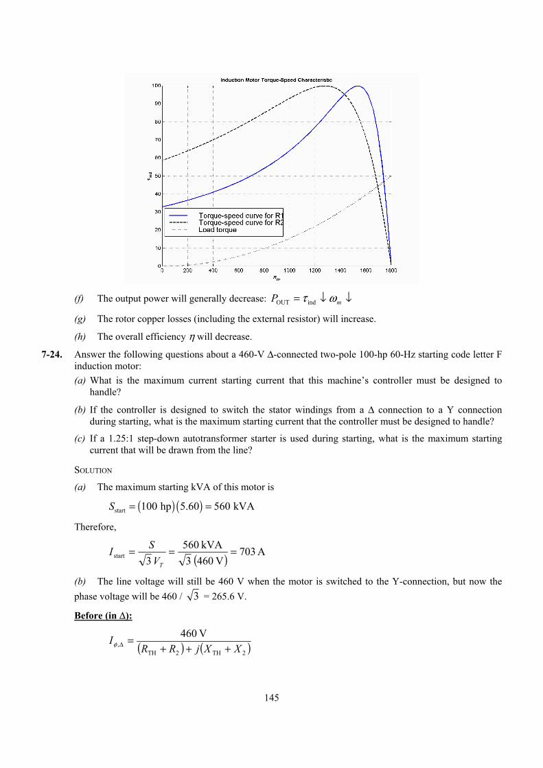
145
(f) The output power will generally decrease: ↓↓= mP ωτ indOUT
(g) The rotor copper losses (including the external resistor) will increase.
(h) The overall efficiency η will decrease.
7-24. Answer the following questions about a 460-V ∆-connected two-pole 100-hp 60-Hz starting code letter F induction motor: (a) What is the maximum current starting current that this machine’s controller must be designed to
handle?
(b) If the controller is designed to switch the stator windings from a ∆ connection to a Y connection during starting, what is the maximum starting current that the controller must be designed to handle?
(c) If a 1.25:1 step-down autotransformer starter is used during starting, what is the maximum starting current that will be drawn from the line?
SOLUTION
(a) The maximum starting kVA of this motor is
( ) ( )start 100 hp 5.60 560 kVAS = =
Therefore,
( ) A 703V 460 3
kVA 560 3start ===
TVSI
(b) The line voltage will still be 460 V when the motor is switched to the Y-connection, but now the phase voltage will be 460 / 3 = 265.6 V.
Before (in ∆):
( ) ( )2TH2TH,
V 460XXjRR
I+++
=∆φ
146
( ) ( )2TH2TH,,
V 9773XXjRR
II L +++== ∆∆ φ
After (in Y):
( ) ( )2TH2THY,Y,
V 65.62XXjRR
II L +++== φ
Therefore the line current will decrease by a factor of 3! The starting current with a ∆-Y starter is
A 2343
A 703start ==I
(c) A 1.25:1 step-down autotransformer reduces the phase voltage on the motor by a factor 0.8. This reduces the phase current and line current in the motor (and on the secondary side of the transformer) by a factor of 0.8. However, the current on the primary of the autotransformer will be reduced by another factor of 0.8, so the total starting current drawn from the line will be 64% of its original value. Therefore, the maximum starting current drawn from the line will be
( ) ( ) A 450A 703 64.0start ==I
7-25. When it is necessary to stop an induction motor very rapidly, many induction motor controllers reverse the direction of rotation of the magnetic fields by switching any two stator leads. When the direction of rotation of the magnetic fields is reversed, the motor develops an induced torque opposite to the current direction of rotation, so it quickly stops and tries to start turning in the opposite direction. If power is removed from the stator circuit at the moment when the rotor speed goes through zero, then the motor has been stopped very rapidly. This technique for rapidly stopping an induction motor is called plugging. The motor of Problem 7-19 is running at rated conditions and is to be stopped by plugging. (a) What is the slip s before plugging?
(b) What is the frequency of the rotor before plugging?
(c) What is the induced torque indτ before plugging?
(d) What is the slip s immediately after switching the stator leads?
(e) What is the frequency of the rotor immediately after switching the stator leads?
(f) What is the induced torque indτ immediately after switching the stator leads?
SOLUTION
(a) The slip before plugging is 0.038 (see Problem 7-19).
(b) The frequency of the rotor before plugging is ( ) ( )0.038 60 Hz 2.28 Hzr ef sf= = =
(c) The induced torque before plugging is 41.1 N⋅m in the direction of motion (see Problem 7-19).
(d) After switching stator leads, the synchronous speed becomes –1800 r/min, while the mechanical speed initially remains 1732 r/min. Therefore, the slip becomes
962.11800
17321800
sync
sync =−
−−=−
=n
nns m
(e) The frequency of the rotor after plugging is ( ) ( )1.962 60 Hz 117.72 Hzr ef sf= = =
(f) The induced torque immediately after switching the stator leads is

147
( ) ( )
2TH 2
ind 2 2sync TH 2 TH 2
3 //
V R sR R s X X
τω
= + + +
( ) ( )
( ) ( ) ( )
2
ind 2 2
3 116.9 V 0.17 /1.962
188.5 rad/s 0.313 0.17 /1.962 0.416 0.420τ Ω
= + Ω + +
( ) ( )
( ) ( ) ( )
2
ind 2 2
3 116.9 V 0.0866
188.5 rad/s 0.313 0.0866 0.416 0.420τ =
+ + +
motion of direction theopposite m,N 9.21ind ⋅=τ
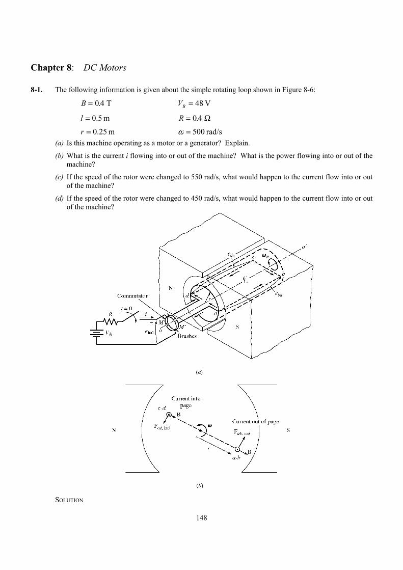
148
Chapter 8: DC Motors
8-1. The following information is given about the simple rotating loop shown in Figure 8-6:
B = 0 4. T V 48=BV
m 5.0=l R = 0 4. Ω
m 25.0=r rad/s 500=ω (a) Is this machine operating as a motor or a generator? Explain.
(b) What is the current i flowing into or out of the machine? What is the power flowing into or out of the machine?
(c) If the speed of the rotor were changed to 550 rad/s, what would happen to the current flow into or out of the machine?
(d) If the speed of the rotor were changed to 450 rad/s, what would happen to the current flow into or out of the machine?
SOLUTION
149
(a) If the speed of rotation ω of the shaft is 500 rad/s, then the voltage induced in the rotating loop will be
ωrlBe 2ind =
( ) ( ) ( ) ( )ind 2 0.25 m 0.5 m 0.4 T 500 rad/s 50 Ve = =
Since the external battery voltage is only 48 V, this machine is operating as a generator, charging the battery.
(b) The current flowing out of the machine is approximately
A 0.5 4.0
V 48 - V 50ind =
Ω=−=
RVei B
(Note that this value is the current flowing while the loop is under the pole faces. When the loop goes beyond the pole faces, inde will momentarily fall to 0 V, and the current flow will momentarily reverse. Therefore, the average current flow over a complete cycle will be somewhat less than 5.0 A.)
(c) If the speed of the rotor were increased to 550 rad/s, the induced voltage of the loop would increase to
ωrlBe 2ind =
( ) ( ) ( ) ( )ind 2 0.25 m 0.5 m 0.4 T 550 rad/s 55 Ve = =
and the current flow out of the machine will increase to
A 5.17 4.0
V 48 - V 55ind =
Ω=−=
RVei B
(d) If the speed of the rotor were decreased to 450 rad/s, the induced voltage of the loop would fall to
ωrlBe 2ind =
( ) ( ) ( ) ( )ind 2 0.25 m 0.5 m 0.4 T 450 rad/s 45 Ve = =
Here, inde is less than BV , so current flows into the loop and the machine is acting as a motor. The current flow into the machine would be
A 5.7 4.0
V 45 - V 84ind =
Ω=−=
ReVi B
8-2. The power converted from one form to another within a dc motor was given by
mAAIEP ωτ indconv ==
Use the equations for EA and indτ [Equations (8-30) and (8-31)] to prove that E IA A = mωτ ind ; that is, prove that the electric power disappearing at the point of power conversion is exactly equal to the mechanical power appearing at that point.
SOLUTION
AAIEP =conv
Substituting Equation (8-30) for AE
( ) AIKP conv ωφ=
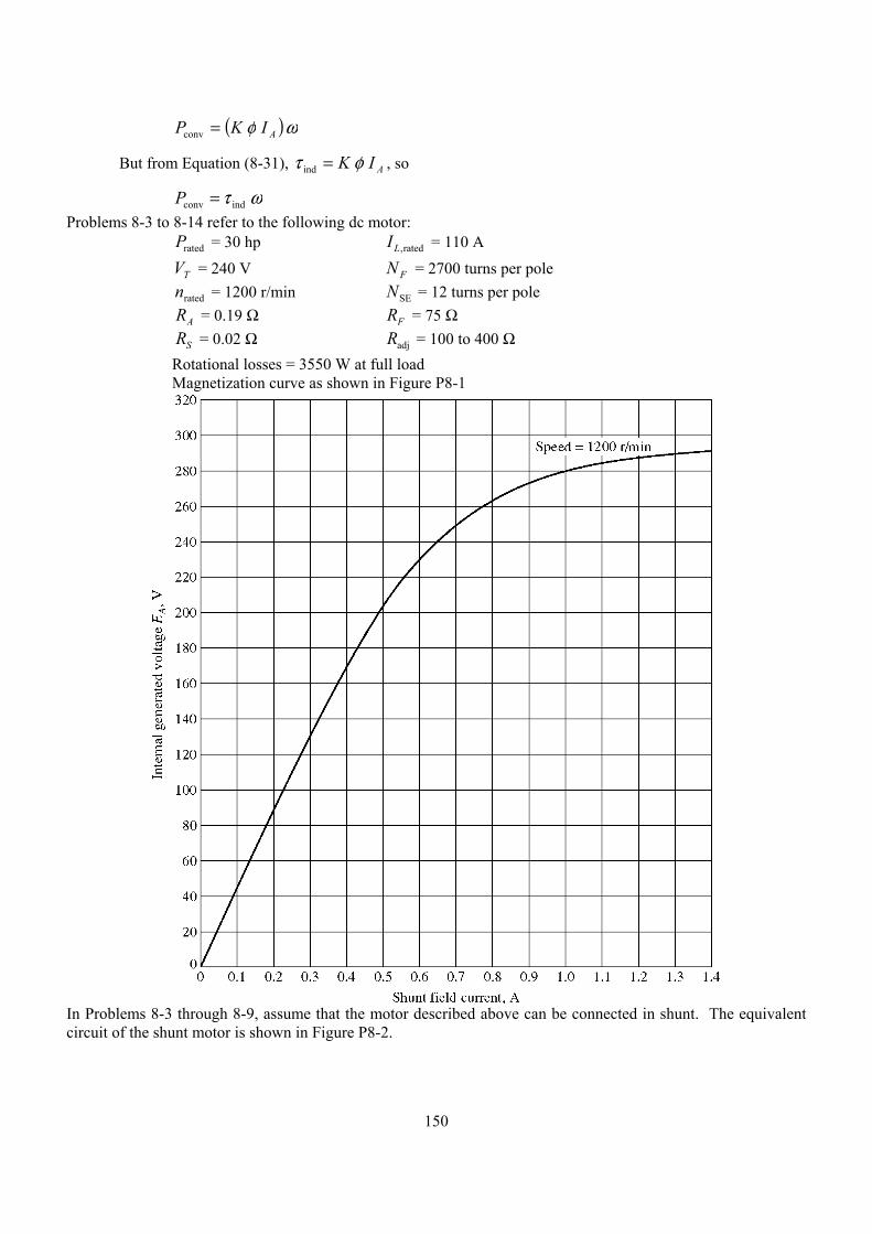
150
( )ωφ conv AIKP =
But from Equation (8-31), AIK ind φτ = , so
ωτ indconv =P Problems 8-3 to 8-14 refer to the following dc motor: Prated = 30 hp IL,rated = 110 A
VT = 240 V N F = 2700 turns per pole nrated = 1200 r/min NSE = 12 turns per pole RA = 0.19 Ω RF = 75 Ω RS = 0.02 Ω Radj = 100 to 400 Ω Rotational losses = 3550 W at full load Magnetization curve as shown in Figure P8-1
In Problems 8-3 through 8-9, assume that the motor described above can be connected in shunt. The equivalent circuit of the shunt motor is shown in Figure P8-2.
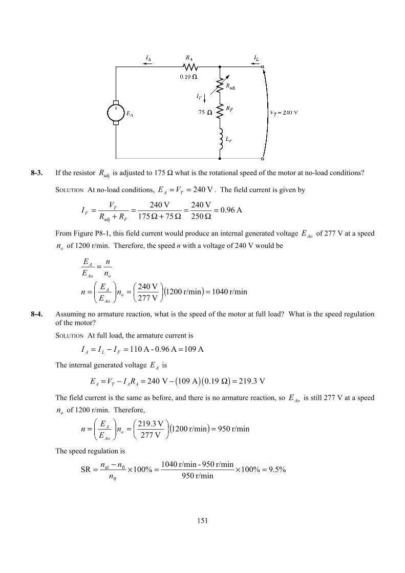
151
8-3. If the resistor Radj is adjusted to 175 Ω what is the rotational speed of the motor at no-load conditions?
SOLUTION At no-load conditions, V 240== TA VE . The field current is given by
A 96.0 250V 240
75 175V 240
adj
=Ω
=Ω+Ω
=+
=F
TF RR
VI
From Figure P8-1, this field current would produce an internal generated voltage AoE of 277 V at a speed
on of 1200 r/min. Therefore, the speed n with a voltage of 240 V would be
oAo
A
nn
EE =
( ) r/min 1040r/min 1200 V 277V 240 =
=
= o
Ao
A nEEn
8-4. Assuming no armature reaction, what is the speed of the motor at full load? What is the speed regulation of the motor?
SOLUTION At full load, the armature current is
A 109 A 0.96 - A 110 ==−= FLA III
The internal generated voltage AE is
( ) ( )240 V 109 A 0.19 219.3 VA T A AE V I R= − = − Ω =
The field current is the same as before, and there is no armature reaction, so AoE is still 277 V at a speed
on of 1200 r/min. Therefore,
( ) r/min 950r/min 1200 V 277V 3.219 =
=
= o
Ao
A nEEn
The speed regulation is
%5.9%100r/min 950
r/min 950 - r/min 1040%100SRfl
flnl =×=×−=n
nn
152
8-5. If the motor is operating at full load and if its variable resistance Radj is increased to 250 Ω, what is the
new speed of the motor? Compare the full-load speed of the motor with Radj = 175 Ω to the full-load
speed with Radj = 250 Ω. (Assume no armature reaction, as in the previous problem.)
SOLUTION If adjR is set to 250 Ω, the field current is now
A 739.0 250V 240
75 250V 240
adj
=Ω
=Ω+Ω
=+
=F
TF RR
VI
Since the motor is still at full load, AE is still 219.3 V. From the magnetization curve (Figure P8-1), this current would produce a voltage AoE of 256 V at a speed on of 1200 r/min. Therefore,
( ) r/min 1028r/min 1200 V 256V 3.219 =
=
= o
Ao
A nEEn
Note that adjR has increased, and as a result the speed of the motor n increased.
8-6. Assume that the motor is operating at full load and that the variable resistor Radj is again 175 Ω. If the
armature reaction is 1200 A⋅turns at full load, what is the speed of the motor? How does it compare to the result for Problem 8-5?
SOLUTION The field current is again 0.96 A, and the motor is again at full load conditions. However, this time there is an armature reaction of 1200 A⋅turns, and the effective field current is
A 516.0 turns2700
turnsA 1200-A 96.0AR* =⋅=−=F
FF NII
From Figure P8-1, this field current would produce an internal generated voltage AoE of 210 V at a speed
on of 1200 r/min. The actual internal generated voltage AE at these conditions is
( )( ) V 3.219 19.0A 109 - V 240 =Ω=−= AATA RIVE
Therefore, the speed n with a voltage of 240 V would be
( ) r/min 1253r/min 1200 V 210V 3.219 =
=
= o
Ao
A nEEn
If all other conditions are the same, the motor with armature reaction runs at a higher speed than the motor without armature reaction.
8-7. If Radj can be adjusted from 100 to 400 Ω, what are the maximum and minimum no-load speeds possible with this motor?
SOLUTION The minimum speed will occur when Radj = 100 Ω, and the maximum speed will occur when
Radj = 400 Ω. The field current when Radj = 100 Ω is:
A 37.1 175V 240
75 100V 240
adj
=Ω
=Ω+Ω
=+
=F
TF RR
VI
From Figure P8-1, this field current would produce an internal generated voltage AoE of 289 V at a speed
on of 1200 r/min. Therefore, the speed n with a voltage of 240 V would be
153
oAo
A
nn
EE =
( ) r/min 997r/min 1200 V 289V 240 =
=
= o
Ao
A nEEn
The field current when Radj = 400 Ω is:
A 505.0 475V 240
75 400V 240
adj
=Ω
=Ω+Ω
=+
=F
TF RR
VI
From Figure P8-1, this field current would produce an internal generated voltage AoE of 207 V at a speed
on of 1200 r/min. Therefore, the speed n with a voltage of 240 V would be
oAo
A
nn
EE =
( ) r/min 1391r/min 1200 V 207V 240 =
=
= o
Ao
A nEEn
8-8. What is the starting current of this machine if it is started by connecting it directly to the power supply VT ? How does this starting current compare to the full-load current of the motor?
SOLUTION The starting current of this machine (ignoring the small field current) is
A 1263 0.19V 240
start, =Ω
==A
TL R
VI
The rated current is 110 A, so the starting current is 11.5 times greater than the full-load current. This much current is extremely likely to damage the motor.
8-9. Plot the torque-speed characteristic of this motor assuming no armature reaction, and again assuming a full-load armature reaction of 1200 A⋅turns.
SOLUTION This problem is best solved with MATLAB, since it involves calculating the torque-speed values at many points. A MATLAB program to calculate and display both torque-speed characteristics is shown below.
% M-file: prob8_9.m% M-file to create a plot of the torque-speed curve of the% the shunt dc motor with and without armature reaction.
% Get the magnetization curve. This file contains the% three variables if_value, ea_value, and n_0.load p81.mat
% First, initialize the values needed in this program.v_t = 240; % Terminal voltage (V)r_f = 75; % Field resistance (ohms)r_adj = 175; % Adjustable resistance (ohms)r_a = 0.19; % Armature resistance (ohms)i_l = 0:2:110; % Line currents (A)n_f = 2700; % Number of turns on fieldf_ar0 = 1200; % Armature reaction @ 110 A (A-t/m)

154
% Calculate the armature current for each load.i_a = i_l - v_t / (r_f + r_adj);
% Now calculate the internal generated voltage for% each armature current.e_a = v_t - i_a * r_a;
% Calculate the armature reaction MMF for each armature% current.f_ar = (i_a / 110) * f_ar0;
% Calculate the effective field current with and without% armature reaction. Ther term i_f_ar is the field current% with armature reaction, and the term i_f_noar is the% field current without armature reaction.i_f_ar = v_t / (r_f + r_adj) - f_ar / n_f;i_f_noar = v_t / (r_f + r_adj);
% Calculate the resulting internal generated voltage at% 1200 r/min by interpolating the motor's magnetization% curve.e_a0_ar = interp1(if_values,ea_values,i_f_ar);e_a0_noar = interp1(if_values,ea_values,i_f_noar);
% Calculate the resulting speed from Equation (8-38).n_ar = ( e_a ./ e_a0_ar ) * n_0;n_noar = ( e_a ./ e_a0_noar ) * n_0;
% Calculate the induced torque corresponding to each% speed from Equations (8-28) and (8-29).t_ind_ar = e_a .* i_a ./ (n_ar * 2 * pi / 60);t_ind_noar = e_a .* i_a ./ (n_noar * 2 * pi / 60);
% Plot the torque-speed curvesfigure(1);plot(t_ind_noar,n_noar,'b-','LineWidth',2.0);hold on;plot(t_ind_ar,n_ar,'k--','LineWidth',2.0);xlabel('\bf\tau_ind (N-m)');ylabel('\bf\itn_m \rm\bf(r/min)');title ('\bfShunt DC Motor Torque-Speed Characteristic');legend('No armature reaction','With armature reaction');axis([ 0 250 800 1250]);grid on;hold off;
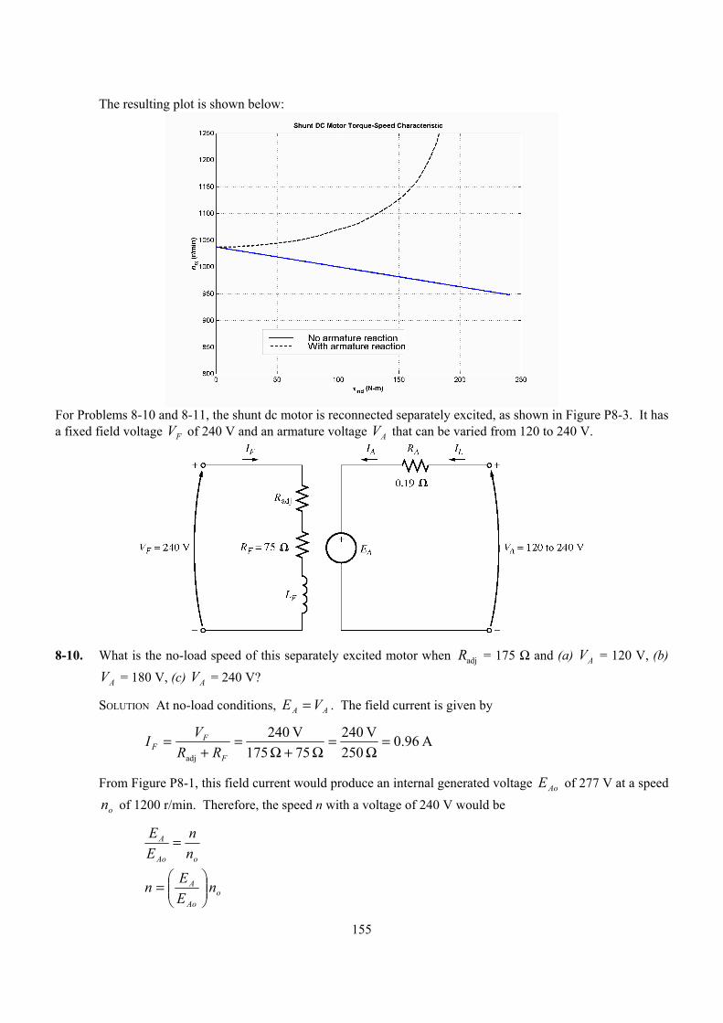
155
The resulting plot is shown below:
For Problems 8-10 and 8-11, the shunt dc motor is reconnected separately excited, as shown in Figure P8-3. It has a fixed field voltage VF of 240 V and an armature voltage VA that can be varied from 120 to 240 V.
8-10. What is the no-load speed of this separately excited motor when Radj = 175 Ω and (a) VA = 120 V, (b)
VA = 180 V, (c) VA = 240 V?
SOLUTION At no-load conditions, AA VE = . The field current is given by
A 96.0 250V 240
75 175V 240
adj
=Ω
=Ω+Ω
=+
=F
FF RR
VI
From Figure P8-1, this field current would produce an internal generated voltage AoE of 277 V at a speed
on of 1200 r/min. Therefore, the speed n with a voltage of 240 V would be
oAo
A
nn
EE =
oAo
A nEEn
=
156
(a) If AV = 120 V, then AE = 120 V, and
( )120 V 1200 r/min 520 r/min277 V
n = =
(a) If AV = 180 V, then AE = 180 V, and
( )180 V 1200 r/min 780 r/min277 V
n = =
(a) If AV = 240 V, then AE = 240 V, and
( )240 V 1200 r/min 1040 r/min277 V
n = =
8-11. For the separately excited motor of Problem 8-10: (a) What is the maximum no-load speed attainable by varying both VA and Radj ?
(b) What is the minimum no-load speed attainable by varying both VA and Radj ?
SOLUTION
(a) The maximum speed will occur with the maximum VA and the maximum Radj . The field current
when Radj = 400 Ω is:
A 505.0 475V 240
75 400V 240
adj
=Ω
=Ω+Ω
=+
=F
TF RR
VI
From Figure P8-1, this field current would produce an internal generated voltage AoE of 207 V at a speed
on of 1200 r/min. At no-load conditions, the maximum internal generated voltage AA VE = = 240 V. Therefore, the speed n with a voltage of 240 V would be
oAo
A
nn
EE =
( ) r/min 1391r/min 1200 V 207V 240 =
=
= o
Ao
A nEEn
(b) The minimum speed will occur with the minimum VA and the minimum Radj . The field current
when Radj = 100 Ω is:
A 37.1 175V 240
75 100V 240
adj
=Ω
=Ω+Ω
=+
=F
TF RR
VI
From Figure P8-1, this field current would produce an internal generated voltage AoE of 289 V at a speed
on of 1200 r/min. At no-load conditions, the minimum internal generated voltage AA VE = = 120 V. Therefore, the speed n with a voltage of 120 V would be
oAo
A
nn
EE =
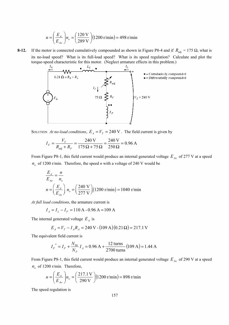
157
( ) r/min 498r/min 1200 V 289V 120 =
=
= o
Ao
A nEEn
8-12. If the motor is connected cumulatively compounded as shown in Figure P8-4 and if Radj = 175 Ω, what is its no-load speed? What is its full-load speed? What is its speed regulation? Calculate and plot the torque-speed characteristic for this motor. (Neglect armature effects in this problem.)
SOLUTION At no-load conditions, V 240== TA VE . The field current is given by
A 96.0 250V 240
75 175V 240
adj
=Ω
=Ω+Ω
=+
=F
TF RR
VI
From Figure P8-1, this field current would produce an internal generated voltage AoE of 277 V at a speed
on of 1200 r/min. Therefore, the speed n with a voltage of 240 V would be
oAo
A
nn
EE =
( )240 V 1200 r/min 1040 r/min277 V
Ao
Ao
En nE
= = =
At full load conditions, the armature current is
A 109 A 0.96 - A 110 ==−= FLA III
The internal generated voltage AE is
( ) ( ) V 1.217 21.0 A 109 - V 240 =Ω=−= AATA RIVE
The equivalent field current is
( ) A 44.1A 109 turns2700
turns12A 96.0SE* =+=+= AF
FF INNII
From Figure P8-1, this field current would produce an internal generated voltage AoE of 290 V at a speed
on of 1200 r/min. Therefore,
( ) r/min 898r/min 1200 V 290V 1.217 =
=
= o
Ao
A nEEn
The speed regulation is

158
%8.15%100r/min 898
r/min 898 - r/min 1040%100SRfl
flnl =×=×−=n
nn
The torque-speed characteristic can best be plotted with a MATLAB program. An appropriate program is shown below.
% M-file: prob8_12.m% M-file to create a plot of the torque-speed curve of the% a cumulatively compounded dc motor without% armature reaction.
% Get the magnetization curve. This file contains the% three variables if_values, ea_values, and n_0.load p81.mat
% First, initialize the values needed in this program.v_t = 240; % Terminal voltage (V)r_f = 75; % Field resistance (ohms)r_adj = 175; % Adjustable resistance (ohms)r_a = 0.21; % Armature + series resistance (ohms)i_l = 0:2:110; % Line currents (A)n_f = 2700; % Number of turns on shunt fieldn_se = 12; % Number of turns on series field
% Calculate the armature current for each load.i_a = i_l - v_t / (r_f + r_adj);
% Now calculate the internal generated voltage for% each armature current.e_a = v_t - i_a * r_a;
% Calculate the effective field current for each armature% current.i_f = v_t / (r_f + r_adj) + (n_se / n_f) * i_a;
% Calculate the resulting internal generated voltage at% 1200 r/min by interpolating the motor's magnetization% curve.e_a0 = interp1(if_values,ea_values,i_f);
% Calculate the resulting speed from Equation (8-38).n = ( e_a ./ e_a0 ) * n_0;
% Calculate the induced torque corresponding to each% speed from Equations (8-28) and (8-29).t_ind = e_a .* i_a ./ (n * 2 * pi / 60);
% Plot the torque-speed curvesfigure(1);plot(t_ind,n,'b-','LineWidth',2.0);xlabel('\bf\tau_ind (N-m)');ylabel('\bf\itn_m \rm\bf(r/min)');title ('\bfCumulatively-Compounded DC Motor Torque-Speed Characteristic');axis([0 250 800 1250]);grid on;
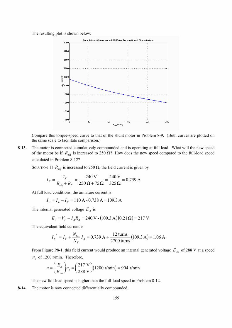
159
The resulting plot is shown below:
Compare this torque-speed curve to that of the shunt motor in Problem 8-9. (Both curves are plotted on
the same scale to facilitate comparison.)
8-13. The motor is connected cumulatively compounded and is operating at full load. What will the new speed of the motor be if Radj is increased to 250 Ω? How does the new speed compared to the full-load speed calculated in Problem 8-12?
SOLUTION If Radj is increased to 250 Ω, the field current is given by
A 739.0 325V 240
75 250V 240
adj
=Ω
=Ω+Ω
=+
=F
TF RR
VI
At full load conditions, the armature current is
A 109.3 A 0.738 - A 110 ==−= FLA III
The internal generated voltage AE is
( ) ( ) V 217 21.0 A 109.3 - V 240 =Ω=−= AATA RIVE
The equivalent field current is
( ) A 06.1A 3.109 turns2700
turns12A 739.0SE* =+=+= AF
FF INNII
From Figure P8-1, this field current would produce an internal generated voltage AoE of 288 V at a speed
on of 1200 r/min. Therefore,
( )217 V 1200 r/min 904 r/min288 V
Ao
Ao
En nE
= = =
The new full-load speed is higher than the full-load speed in Problem 8-12.
8-14. The motor is now connected differentially compounded.
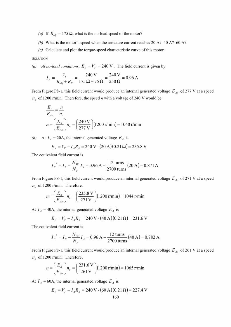
160
(a) If Radj = 175 Ω, what is the no-load speed of the motor?
(b) What is the motor’s speed when the armature current reaches 20 A? 40 A? 60 A?
(c) Calculate and plot the torque-speed characteristic curve of this motor.
SOLUTION
(a) At no-load conditions, V 240== TA VE . The field current is given by
A 96.0 250V 240
75 175V 240
adj
=Ω
=Ω+Ω
=+
=F
TF RR
VI
From Figure P8-1, this field current would produce an internal generated voltage AoE of 277 V at a speed
on of 1200 r/min. Therefore, the speed n with a voltage of 240 V would be
oAo
A
nn
EE =
( ) r/min 1040r/min 1200 V 277V 240 =
=
= o
Ao
A nEEn
(b) At AI = 20A, the internal generated voltage AE is
( ) ( ) V 8.235 21.0 A 20 - V 240 =Ω=−= AATA RIVE
The equivalent field current is
( ) A 871.0A 20 turns2700
turns12A 96.0SE* =−=−= AF
FF INNII
From Figure P8-1, this field current would produce an internal generated voltage AoE of 271 V at a speed
on of 1200 r/min. Therefore,
( ) r/min 1044r/min 1200 V 271V 8.235 =
=
= o
Ao
A nEEn
At AI = 40A, the internal generated voltage AE is
( ) ( ) V 6.231 21.0 A 40 - V 240 =Ω=−= AATA RIVE
The equivalent field current is
( ) A 782.0A 40 turns2700
turns12A 96.0SE* =−=−= AF
FF INNII
From Figure P8-1, this field current would produce an internal generated voltage AoE of 261 V at a speed
on of 1200 r/min. Therefore,
( ) r/min 1065r/min 1200 V 261V 6.231 =
=
= o
Ao
A nEEn
At AI = 60A, the internal generated voltage AE is
( ) ( ) V 4.227 21.0 A 60 - V 240 =Ω=−= AATA RIVE
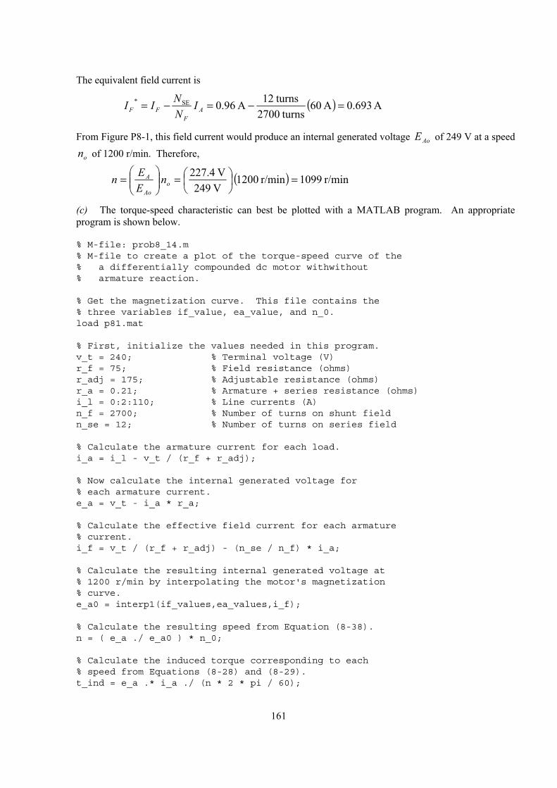
161
The equivalent field current is
( ) A 693.0A 60 turns2700
turns12A 96.0SE* =−=−= AF
FF INNII
From Figure P8-1, this field current would produce an internal generated voltage AoE of 249 V at a speed
on of 1200 r/min. Therefore,
( ) r/min 1099r/min 1200 V 249V 4.227 =
=
= o
Ao
A nEEn
(c) The torque-speed characteristic can best be plotted with a MATLAB program. An appropriate program is shown below.
% M-file: prob8_14.m% M-file to create a plot of the torque-speed curve of the% a differentially compounded dc motor withwithout% armature reaction.
% Get the magnetization curve. This file contains the% three variables if_value, ea_value, and n_0.load p81.mat
% First, initialize the values needed in this program.v_t = 240; % Terminal voltage (V)r_f = 75; % Field resistance (ohms)r_adj = 175; % Adjustable resistance (ohms)r_a = 0.21; % Armature + series resistance (ohms)i_l = 0:2:110; % Line currents (A)n_f = 2700; % Number of turns on shunt fieldn_se = 12; % Number of turns on series field
% Calculate the armature current for each load.i_a = i_l - v_t / (r_f + r_adj);
% Now calculate the internal generated voltage for% each armature current.e_a = v_t - i_a * r_a;
% Calculate the effective field current for each armature% current.i_f = v_t / (r_f + r_adj) - (n_se / n_f) * i_a;
% Calculate the resulting internal generated voltage at% 1200 r/min by interpolating the motor's magnetization% curve.e_a0 = interp1(if_values,ea_values,i_f);
% Calculate the resulting speed from Equation (8-38).n = ( e_a ./ e_a0 ) * n_0;
% Calculate the induced torque corresponding to each% speed from Equations (8-28) and (8-29).t_ind = e_a .* i_a ./ (n * 2 * pi / 60);
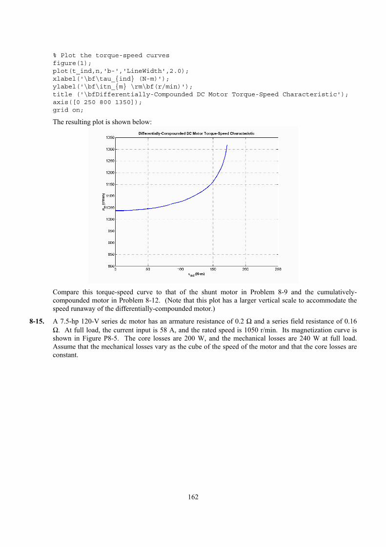
162
% Plot the torque-speed curvesfigure(1);plot(t_ind,n,'b-','LineWidth',2.0);xlabel('\bf\tau_ind (N-m)');ylabel('\bf\itn_m \rm\bf(r/min)');title ('\bfDifferentially-Compounded DC Motor Torque-Speed Characteristic');axis([0 250 800 1350]);grid on;
The resulting plot is shown below:
Compare this torque-speed curve to that of the shunt motor in Problem 8-9 and the cumulatively-
compounded motor in Problem 8-12. (Note that this plot has a larger vertical scale to accommodate the speed runaway of the differentially-compounded motor.)
8-15. A 7.5-hp 120-V series dc motor has an armature resistance of 0.2 Ω and a series field resistance of 0.16 Ω. At full load, the current input is 58 A, and the rated speed is 1050 r/min. Its magnetization curve is shown in Figure P8-5. The core losses are 200 W, and the mechanical losses are 240 W at full load. Assume that the mechanical losses vary as the cube of the speed of the motor and that the core losses are constant.
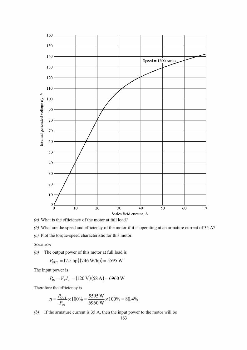
163
(a) What is the efficiency of the motor at full load?
(b) What are the speed and efficiency of the motor if it is operating at an armature current of 35 A?
(c) Plot the torque-speed characteristic for this motor.
SOLUTION
(a) The output power of this motor at full load is
( ) ( ) W 5595W/hp 746 hp 5.7OUT ==P
The input power is
( ) ( ) W 6960A 58 V 120IN === LT IVP
Therefore the efficiency is
%4.80%100W 6960W 5595%100
IN
OUT =×=×=P
Pη
(b) If the armature current is 35 A, then the input power to the motor will be
164
( ) ( ) W 4200A 35 V 120IN === LT IVP
The internal generated voltage at this condition is
( ) ( ) ( ) V 4.107 16.0 20.0 A 35 - V 1202 =Ω+Ω=+−= SAATA RRIVE
and the internal generated voltage at rated conditions is
( ) ( ) ( ) V 1.99 16.0 20.0 A 58 - V 1201 =Ω+Ω=+−= SAATA RRIVE
The final speed is given by the equation
11,
22,
22
22
1
2
nEnE
KK
EE
Ao
Ao
A
A ==ωφωφ
since the ratio 1,2, / AoAo EE is the same as the ratio 12 /φφ . Therefore, the final speed is
12,
1,
1
22 n
EE
EEn
Ao
Ao
A
A=
The internal generated voltage 2,AoE for a current of 35 A and a speed of on = 1200 r/min is 2,AoE = 115
V, and the internal generated voltage 1,AoE for a current of 58 A and a speed of on = 1200 r/min is 1,AoE = 134 V.
( ) r/min 1326r/min 1050 V 115V 134
V 99.1V 4.107
12,
1,
1
22 =
== n
EE
EEn
Ao
Ao
A
A
The power converted from electrical to mechanical form is
( ) ( ) W 3759A 35 V 4.107conv === AAIEP
The core losses in the motor are 200 W, and the mechanical losses in the motor are
( ) ( ) W 483W 240r/min 1050r/min 1326W 240
33
1
2mech =
=
=
nnP
Therefore, the output power is
W 3076 W 200 -W 483 -W 3759coremechconvOUT ==−−= PPPP
and the efficiency is
%2.73%100W 4200W 3076%100
IN
OUT =×=×=P
Pη
(c) A MATLAB program to plot the torque-speed characteristic of this motor is shown below:
% M-file: prob8_15.m% M-file to create a plot of the torque-speed curve of the% the series dc motor in Problem 8-15.
% Get the magnetization curve. This file contains the% three variables if_value, ea_value, and n_0.load p85.mat
% First, initialize the values needed in this program.
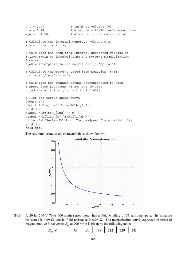
165
v_t = 120; % Terminal voltage (V)r_a = 0.36; % Armature + field resistance (ohms)i_a = 9:1:58; % Armature (line) currents (A)
% Calculate the internal generate voltage e_a.e_a = v_t - i_a * r_a;
% Calculate the resulting internal generated voltage at% 1200 r/min by interpolating the motor's magnetization% curve.e_a0 = interp1(if_values,ea_values,i_a,'spline');
% Calculate the motor's speed from Equation (8-38).n = (e_a ./ e_a0) * n_0;
% Calculate the induced torque corresponding to each% speed from Equations (8-28) and (8-29).t_ind = e_a .* i_a ./ (n * 2 * pi / 60);
% Plot the torque-speed curvefigure(1);plot(t_ind,n,'b-','LineWidth',2.0);hold on;xlabel('\bf\tau_ind (N-m)');ylabel('\bf\itn_m \rm\bf(r/min)');title ('\bfSeries DC Motor Torque-Speed Characteristic');grid on;hold off;
The resulting torque-speed characteristic is shown below:
8-16. A 20-hp 240-V 76-A 900 r/min series motor has a field winding of 33 turns per pole. Its armature
resistance is 0.09 Ω, and its field resistance is 0.06 Ω. The magnetization curve expressed in terms of magnetomotive force versus EA at 900 r/min is given by the following table:
EA , V 95 150 188 212 229 243
166
F, A turns⋅ 500 1000 1500 2000 2500 3000
Armature reaction is negligible in this machine. (a) Compute the motor’s torque, speed, and output power at 33, 67, 100, and 133 percent of full-load
armature current. (Neglect rotational losses.)
(b) Plot the terminal characteristic of this machine.
SOLUTION Note that this magnetization curve has been stored in a file called prob8_16.mat. The contents of the file are an array of mmf_values, an array of ea_values, and the term n_0. Because the data in the file is relatively sparse, it is important that interpolation be done using smooth curves, so be sure to specify the 'spline' option in the MATLAB interp1 function:
Eao = interp1(mmf_values,ea_values,mmf,'spline')
(a) This calculation must be performed for armature currents of 25.3 A, 50.7 A, 76 A, and 101.3 A.
If AI = 23.3 A, then
( ) ( ) ( ) V 2.236 06.0 09.0 A 25.3 - V 240 =Ω+Ω=+−= SAATA RRIVE
The magnetomotive force is ( ) ( ) turnsA 835A 25.3 turns33 ⋅=== ANIF , which produces a voltage
AoE of 134 V at on = 900 r/min. Therefore the speed of the motor at these conditions is
( ) r/min 1586r/min 900 V 134V 236.2 === o
Ao
A nEEn
The power converted from electrical to mechanical form is
( ) ( ) W 5976A 25.3 V 2.236conv === AAIEP
Since the rotational losses are ignored, this is also the output power of the motor. The induced torque is
( )
mN 36
s 60min 1
r 1rad 2 r/min 1586
W 5976convind ⋅=
==πω
τm
P
If AI = 50.7 A, then
( ) ( ) ( ) V 4.232 06.0 09.0 A 50.7 - V 240 =Ω+Ω=+−= SAATA RRIVE
The magnetomotive force is ( ) ( ) turnsA 1672A 50.7 turns33 ⋅=== ANIF , which produces a voltage
AoE of 197 V at on = 900 r/min. Therefore the speed of the motor at these conditions is
( ) r/min 1062r/min 900 V 197V 232.4 === o
Ao
A nEEn
The power converted from electrical to mechanical form is
( ) ( ) W 780,11A 50.7 V 4.232conv === AAIEP
Since the rotational losses are ignored, this is also the output power of the motor. The induced torque is
167
( )
mN 106
s 60min 1
r 1rad 2 r/min 1062
W 780,11convind ⋅=
==πω
τm
P
If AI = 76 A, then
( ) ( ) ( ) V 6.228 06.0 09.0 A 76 - V 240 =Ω+Ω=+−= SAATA RRIVE
The magnetomotive force is ( ) ( ) turnsA 2508A 76 turns33 ⋅=== ANIF , which produces a voltage
AoE of 229 V at on = 900 r/min. Therefore the speed of the motor at these conditions is
( ) r/min 899r/min 900 V 229V 228.6 === o
Ao
A nEEn
The power converted from electrical to mechanical form is
( ) ( ) W 370,17A 76 V 6.228conv === AAIEP
Since the rotational losses are ignored, this is also the output power of the motor. The induced torque is
( )
mN 185
s 60min 1
r 1rad 2 r/min 899
W 370,17convind ⋅=
==πω
τm
P
If AI = 101.3 A, then
( ) ( ) ( ) V 8.224 06.0 09.0 A 101.3 - V 240 =Ω+Ω=+−= SAATA RRIVE
The magnetomotive force is ( ) ( ) turnsA 3343A 101.3 turns33 ⋅=== ANIF , which produces a voltage AoE of 252 V at on = 900 r/min. Therefore the speed of the motor at these conditions is
( ) r/min 803r/min 900 V 252V 224.8 === o
Ao
A nEEn
The power converted from electrical to mechanical form is
( ) ( ) W 770,22A 101.3 V 8.224conv === AAIEP
Since the rotational losses are ignored, this is also the output power of the motor. The induced torque is
( )
convind
22,770 W 271 N m2 rad 1 min803 r/min
1 r 60 sm
Pτ πω= = = ⋅
(b) A MATLAB program to plot the torque-speed characteristic of this motor is shown below:
% M-file: prob8_16.m% M-file to create a plot of the torque-speed curve of the% the series dc motor in Problem 8-16.
% Get the magnetization curve. This file contains the% three variables mmf_values, ea_values, and n_0.load prob8_16.mat
% First, initialize the values needed in this program.
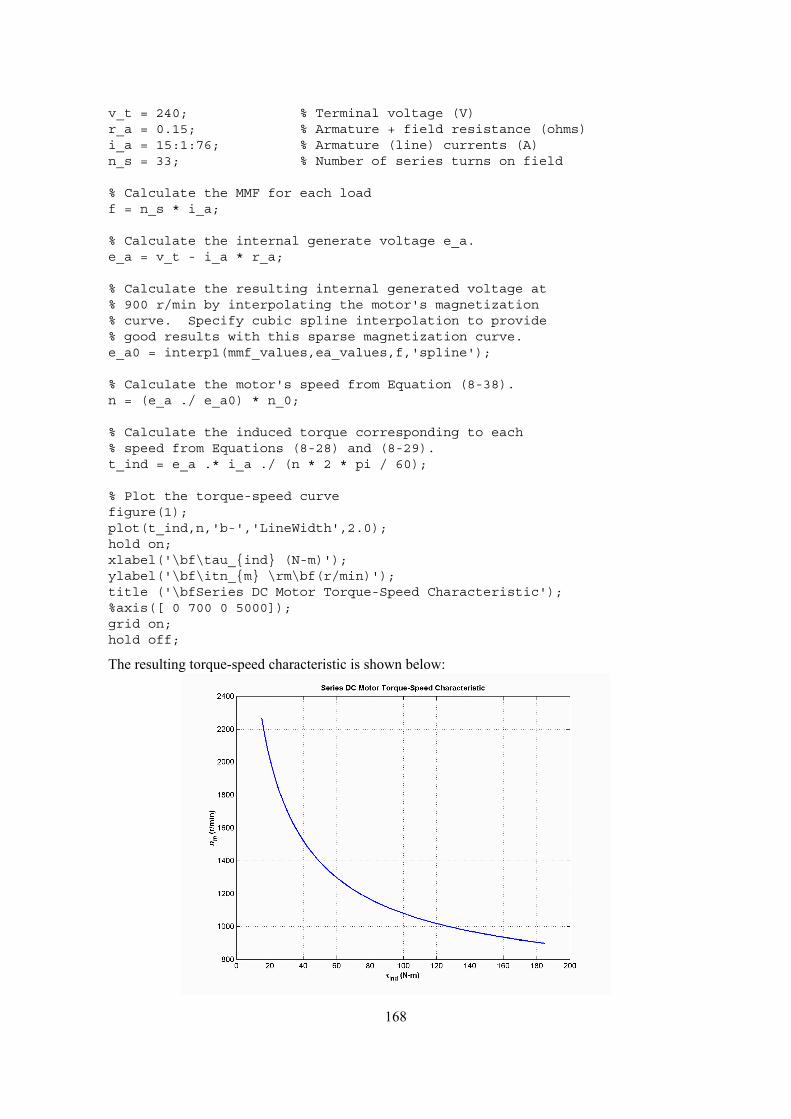
168
v_t = 240; % Terminal voltage (V)r_a = 0.15; % Armature + field resistance (ohms)i_a = 15:1:76; % Armature (line) currents (A)n_s = 33; % Number of series turns on field
% Calculate the MMF for each loadf = n_s * i_a;
% Calculate the internal generate voltage e_a.e_a = v_t - i_a * r_a;
% Calculate the resulting internal generated voltage at% 900 r/min by interpolating the motor's magnetization% curve. Specify cubic spline interpolation to provide% good results with this sparse magnetization curve.e_a0 = interp1(mmf_values,ea_values,f,'spline');
% Calculate the motor's speed from Equation (8-38).n = (e_a ./ e_a0) * n_0;
% Calculate the induced torque corresponding to each% speed from Equations (8-28) and (8-29).t_ind = e_a .* i_a ./ (n * 2 * pi / 60);
% Plot the torque-speed curvefigure(1);plot(t_ind,n,'b-','LineWidth',2.0);hold on;xlabel('\bf\tau_ind (N-m)');ylabel('\bf\itn_m \rm\bf(r/min)');title ('\bfSeries DC Motor Torque-Speed Characteristic');%axis([ 0 700 0 5000]);grid on;hold off;
The resulting torque-speed characteristic is shown below:
169
8-17. A 300-hp 440-V 560-A, 863 r/min shunt dc motor has been tested, and the following data were taken:
Blocked-rotor test:
VA = 16 3. V exclusive of brushes VF = 440 V
I A = 500 A IF = 886. A
No-load operation:
VA = 16 3. V including brushes IF = 8 76. A
IA = 231. A r/min 863=n
What is this motor’s efficiency at the rated conditions? [Note: Assume that (1) the brush voltage drop is 2 V; (2) the core loss is to be determined at an armature voltage equal to the armature voltage under full load; and (3) stray load losses are 1 percent of full load.]
SOLUTION The armature resistance of this motor is
Ω=== 0326.0A 500V 16.3
br,
br,
A
AA I
VR
Under no-load conditions, the core and mechanical losses taken together (that is, the rotational losses) of this motor are equal to the product of the internal generated voltage AE and the armature current AI , since this is no output power from the motor at no-load conditions. Therefore, the rotational losses at rated speed can be found as
( ) ( )brush 442 V 2 V 23.1 A 0.0326 439.2 VA A A AE V V I R= − − = − − Ω =
( ) ( )rot conv 439.2 V 23.1 A 10.15 kWA AP P E I= = = =
The input power to the motor at full load is
( ) ( )IN 440 V 560 A 246.4 kWT LP V I= = =
The output power from the motor at full load is
straybrushrotCUINOUT PPPPPP −−−−=
The copper losses are
( ) ( ) ( ) ( ) kW 1.14A 8.86 V 440 0326.0A 560 22CU =+Ω=+= FFAA IVRIP
The brush losses are
( ) ( ) W 1120A 560 V 2brushbrush === AIVP
Therefore,
straybrushrotCUINOUT PPPPPP −−−−=
kW 218.6 kW 2.46 -kW 1.12 -kW 10.15 -kW 14.1-kW 4.246OUT ==P
The motor’s efficiency at full load is
%7.88%100kW 246.4kW 18.62%100
IN
OUT =×=×=P
Pη
Problems 8-18 to 8-21 refer to a 240-V 100-A dc motor which has both shunt and series windings. Its characteristics are
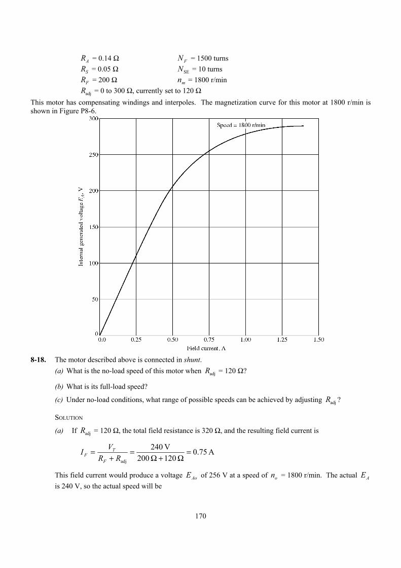
170
RA = 0.14 Ω N F = 1500 turns RS = 0.05 Ω NSE = 10 turns RF = 200 Ω nm = 1800 r/min Radj = 0 to 300 Ω, currently set to 120 Ω This motor has compensating windings and interpoles. The magnetization curve for this motor at 1800 r/min is shown in Figure P8-6.
8-18. The motor described above is connected in shunt.
(a) What is the no-load speed of this motor when Radj = 120 Ω?
(b) What is its full-load speed?
(c) Under no-load conditions, what range of possible speeds can be achieved by adjusting Radj ?
SOLUTION
(a) If Radj = 120 Ω, the total field resistance is 320 Ω, and the resulting field current is
A 75.0 120 200
V 240
adj
=Ω+Ω
=+
=RR
VIF
TF
This field current would produce a voltage AoE of 256 V at a speed of on = 1800 r/min. The actual AE is 240 V, so the actual speed will be
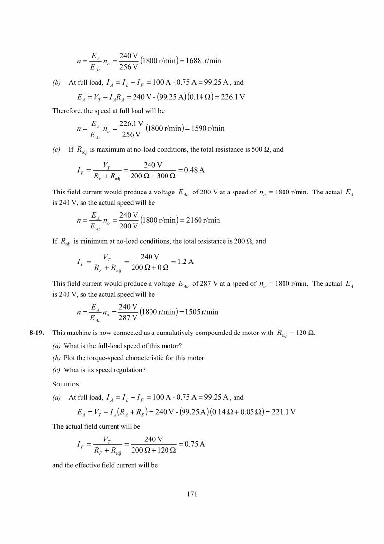
171
( ) r/min 1688r/min 1800 V 256V 240 === o
Ao
A nEEn
(b) At full load, A 99.25 A 0.75 - A 100 ==−= FLA III , and
( ) ( ) V 1.226 14.0 A 99.25 - V 240 =Ω=−= AATA RIVE
Therefore, the speed at full load will be
( ) r/min 1590r/min 1800 V 256V 226.1 === o
Ao
A nEEn
(c) If Radj is maximum at no-load conditions, the total resistance is 500 Ω, and
A 48.0 300 200
V 240
adj
=Ω+Ω
=+
=RR
VIF
TF
This field current would produce a voltage AoE of 200 V at a speed of on = 1800 r/min. The actual AE is 240 V, so the actual speed will be
( ) r/min 2160r/min 1800 V 200V 240 === o
Ao
A nEEn
If Radj is minimum at no-load conditions, the total resistance is 200 Ω, and
A 2.1 0 200
V 240
adj
=Ω+Ω
=+
=RR
VIF
TF
This field current would produce a voltage AoE of 287 V at a speed of on = 1800 r/min. The actual AE is 240 V, so the actual speed will be
( ) r/min 1505r/min 1800 V 287V 240 === o
Ao
A nEEn
8-19. This machine is now connected as a cumulatively compounded dc motor with Radj = 120 Ω.
(a) What is the full-load speed of this motor?
(b) Plot the torque-speed characteristic for this motor.
(c) What is its speed regulation?
SOLUTION
(a) At full load, A 99.25 A 0.75 - A 100 ==−= FLA III , and
( ) ( ) ( ) V 1.221 05.0 14.0 A 99.25 - V 240 =Ω+Ω=+−= SAATA RRIVE
The actual field current will be
A 75.0 120 200
V 240
adj
=Ω+Ω
=+
=RR
VIF
TF
and the effective field current will be
172
( ) A 28.1A 25.99 turns1500
turns8A 75.0SE* =+=+= AF
FF INNII
This field current would produce a voltage AoE of 288 V at a speed of on = 1800 r/min. The actual AE is 240 V, so the actual speed at full load will be
( ) r/min 1382r/min 1800 V 288V 221.1 === o
Ao
A nEEn
(b) A MATLAB program to calculate the torque-speed characteristic of this motor is shown below:
% M-file: prob8_19.m% M-file to create a plot of the torque-speed curve of the% a cumulatively compounded dc motor.
% Get the magnetization curve. This file contains the% three variables if_values, ea_values, and n_0.load p86.mat
% First, initialize the values needed in this program.v_t = 240; % Terminal voltage (V)r_f = 200; % Field resistance (ohms)r_adj = 120; % Adjustable resistance (ohms)r_a = 0.19; % Armature + series resistance (ohms)i_l = 0:2:100; % Line currents (A)n_f = 1500; % Number of turns on shunt fieldn_se = 8; % Number of turns on series field
% Calculate the armature current for each load.i_a = i_l - v_t / (r_f + r_adj);
% Now calculate the internal generated voltage for% each armature current.e_a = v_t - i_a * r_a;
% Calculate the effective field current for each armature% current.i_f = v_t / (r_f + r_adj) + (n_se / n_f) * i_a;
% Calculate the resulting internal generated voltage at% 1800 r/min by interpolating the motor's magnetization% curve.e_a0 = interp1(if_values,ea_values,i_f);
% Calculate the resulting speed from Equation (8-38).n = ( e_a ./ e_a0 ) * n_0;
% Calculate the induced torque corresponding to each% speed from Equations (8-28) and (8-29).t_ind = e_a .* i_a ./ (n * 2 * pi / 60);
% Plot the torque-speed curvesfigure(1);plot(t_ind,n,'b-','LineWidth',2.0);xlabel('\bf\tau_ind (N-m)');
173
ylabel('\bf\itn_m \rm\bf(r/min)');title ('\bfCumulatively-Compounded DC Motor Torque-Speed Characteristic');axis([0 160 1000 2000]);grid on;
The resulting torque-speed characteristic is shown below:
(c) The no-load speed of this machine is the same as the no-load speed of the corresponding shunt dc
motor with adjR = 120 Ω, which is 1688 r/min. The speed regulation of this motor is thus
%1.22%100r/min 1382
r/min 1382 - r/min 1688%100SRfl
flnl =×=×−=n
nn
8-20. The motor is reconnected differentially compounded with Radj = 120 Ω. Derive the shape of its torque-speed characteristic.
SOLUTION A MATLAB program to calculate the torque-speed characteristic of this motor is shown below:
% M-file: prob8_20.m% M-file to create a plot of the torque-speed curve of the% a differentially compounded dc motor.
% Get the magnetization curve. This file contains the% three variables if_values, ea_values, and n_0.load p86.mat
% First, initialize the values needed in this program.v_t = 240; % Terminal voltage (V)r_f = 200; % Field resistance (ohms)r_adj = 120; % Adjustable resistance (ohms)r_a = 0.19; % Armature + series resistance (ohms)i_l = 0:2:45; % Line currents (A)n_f = 1500; % Number of turns on shunt fieldn_se = 8; % Number of turns on series field
% Calculate the armature current for each load.
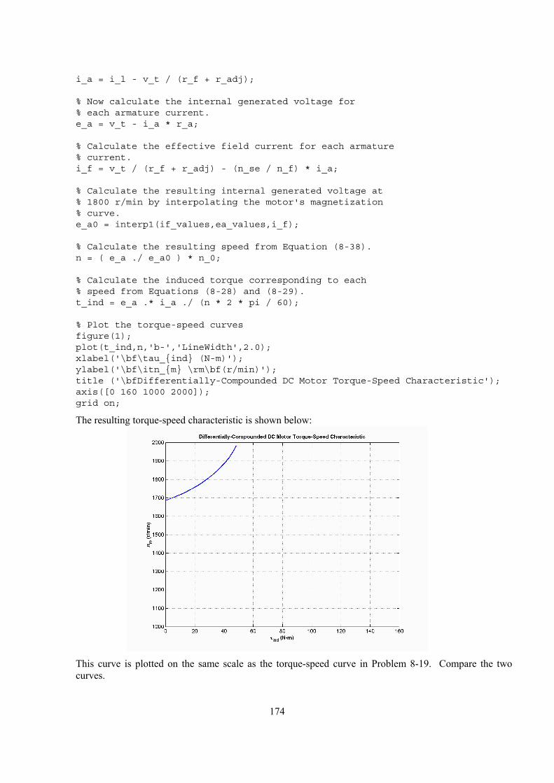
174
i_a = i_l - v_t / (r_f + r_adj);
% Now calculate the internal generated voltage for% each armature current.e_a = v_t - i_a * r_a;
% Calculate the effective field current for each armature% current.i_f = v_t / (r_f + r_adj) - (n_se / n_f) * i_a;
% Calculate the resulting internal generated voltage at% 1800 r/min by interpolating the motor's magnetization% curve.e_a0 = interp1(if_values,ea_values,i_f);
% Calculate the resulting speed from Equation (8-38).n = ( e_a ./ e_a0 ) * n_0;
% Calculate the induced torque corresponding to each% speed from Equations (8-28) and (8-29).t_ind = e_a .* i_a ./ (n * 2 * pi / 60);
% Plot the torque-speed curvesfigure(1);plot(t_ind,n,'b-','LineWidth',2.0);xlabel('\bf\tau_ind (N-m)');ylabel('\bf\itn_m \rm\bf(r/min)');title ('\bfDifferentially-Compounded DC Motor Torque-Speed Characteristic');axis([0 160 1000 2000]);grid on;
The resulting torque-speed characteristic is shown below:
This curve is plotted on the same scale as the torque-speed curve in Problem 8-19. Compare the two
curves.
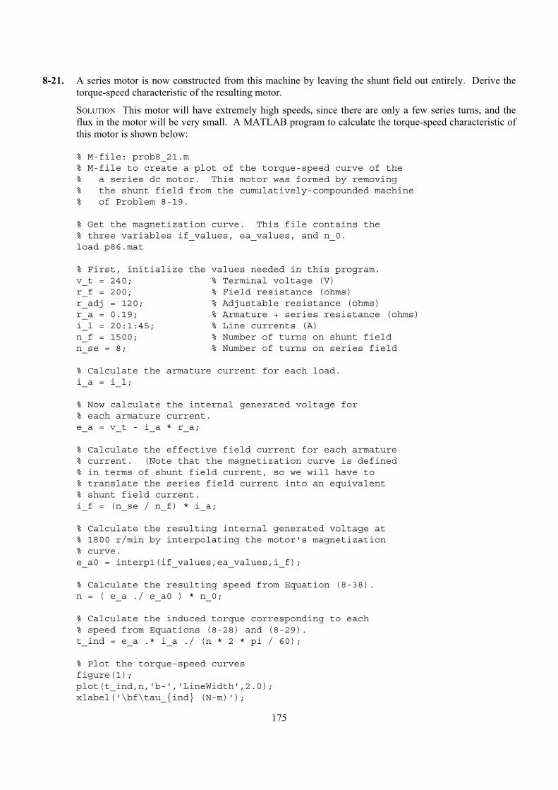
175
8-21. A series motor is now constructed from this machine by leaving the shunt field out entirely. Derive the torque-speed characteristic of the resulting motor.
SOLUTION This motor will have extremely high speeds, since there are only a few series turns, and the flux in the motor will be very small. A MATLAB program to calculate the torque-speed characteristic of this motor is shown below:
% M-file: prob8_21.m% M-file to create a plot of the torque-speed curve of the% a series dc motor. This motor was formed by removing% the shunt field from the cumulatively-compounded machine% of Problem 8-19.
% Get the magnetization curve. This file contains the% three variables if_values, ea_values, and n_0.load p86.mat
% First, initialize the values needed in this program.v_t = 240; % Terminal voltage (V)r_f = 200; % Field resistance (ohms)r_adj = 120; % Adjustable resistance (ohms)r_a = 0.19; % Armature + series resistance (ohms)i_l = 20:1:45; % Line currents (A)n_f = 1500; % Number of turns on shunt fieldn_se = 8; % Number of turns on series field
% Calculate the armature current for each load.i_a = i_l;
% Now calculate the internal generated voltage for% each armature current.e_a = v_t - i_a * r_a;
% Calculate the effective field current for each armature% current. (Note that the magnetization curve is defined% in terms of shunt field current, so we will have to% translate the series field current into an equivalent% shunt field current.i_f = (n_se / n_f) * i_a;
% Calculate the resulting internal generated voltage at% 1800 r/min by interpolating the motor's magnetization% curve.e_a0 = interp1(if_values,ea_values,i_f);
% Calculate the resulting speed from Equation (8-38).n = ( e_a ./ e_a0 ) * n_0;
% Calculate the induced torque corresponding to each% speed from Equations (8-28) and (8-29).t_ind = e_a .* i_a ./ (n * 2 * pi / 60);
% Plot the torque-speed curvesfigure(1);plot(t_ind,n,'b-','LineWidth',2.0);xlabel('\bf\tau_ind (N-m)');
176
ylabel('\bf\itn_m \rm\bf(r/min)');title ('\bfSeries DC Motor Torque-Speed Characteristic');grid on;
The resulting torque-speed characteristic is shown below:
The extreme speeds in this characteristic are due to the very light flux in the machine. To make a
practical series motor out of this machine, it would be necessary to include 20 to 30 series turns instead of 8.
8-22. An automatic starter circuit is to be designed for a shunt motor rated at 20 hp, 240 V, and 80 A. The armature resistance of the motor is 0.12 Ω, and the shunt field resistance is 40 Ω. The motor is to start with no more than 250 percent of its rated armature current, and as soon as the current falls to rated value, a starting resistor stage is to be cut out. How many stages of starting resistance are needed, and how big should each one be?
SOLUTION The rated line current of this motor is 80 A, and the rated armature current is FLA III −= = 80 A – 6 A = 74 A. The maximum desired starting current is (2.5)(74 A) = 185 A. Therefore, the total initial starting resistance must be
Ω==+ 297.1A 185V 240
start,1RRA
Ω=Ω−Ω= 177.1 12.0 297.1start,1R
The current will fall to rated value when AE rises to ( ) ( ) V 144A 74 1.297-V 240 =Ω=AE
At that time, we want to cut out enough resistance to get the current back up to 185 A. Therefore,
Ω==+ 519.0A 185
V 144-V 240start,2RRA
Ω=Ω−Ω= 399.0 12.0 519.0start,2R
With this resistance in the circuit, the current will fall to rated value when AE rises to ( ) ( ) V 6.201A 74 0.519-V 240 =Ω=AE
At that time, we want to cut out enough resistance to get the current back up to 185 A. Therefore,
177
Ω==+ 208.0A 185
V 201.6-V 240start,3RRA
Ω=Ω−Ω= 088.0 12.0 208.0start,3R
With this resistance in the circuit, the current will fall to rated value when AE rises to ( ) ( ) V 6.224A 74 0.208-V 240 =Ω=AE
If the resistance is cut out when AE reaches 224.6 V, the resulting current is
A 185 A 3.128 0.12
V 224.6 - V 240 <=Ω
=AI ,
so there are only three stages of starting resistance. The three stages of starting resistance can be found from the resistance in the circuit at each state during starting.
Ω=++= 177.1321start,1 RRRR
Ω=+= 399.032start,2 RRR
Ω== 088.03start,3 RR
Therefore, the starting resistances are
Ω= 778.01R Ω= 311.02R Ω= 088.03R
178
Chapter 9: Transmission Lines
9-1. Calculate the dc resistance in ohms per kilometer for an aluminum conductor with a 3 cm diameter.
SOLUTION The resistance per meter of aluminum conductor is given by Equation (9-2):
DC 2rA rρ ρ
π= =
where ρ = 2.83 × 10⁻⁸ Ω-m. This value is
( )
( )
85
DC 2
2.83 10 -m4.004 10 /m
0.015 mr
π
−−× Ω
= = × Ω
Therefore the total DC resistance per kilometer would be
( )5DC
1000 m4.004 10 /m 0.040 /km1 km
R − = × Ω = Ω
9-2. Calculate the dc resistance in ohms per mile for a hard-drawn copper conductor with a 1 inch diameter. (Note that 1 mile = 1.609 km).
SOLUTION The resistance per meter of hard-drawn copper conductor is given by Equation (9-2):
DC 2rA rρ ρ
π= =
where ρ = 1.77 × 10⁻⁸ Ω-m. Note that the radius in this equation must be in units of meters. This value is
( )
( )
85
DC 2
1.77 10 -m3.493 10 /m
0.0254 m0.5 in1 in
rπ
−−× Ω
= = × Ω
Therefore the total DC resistance per mile would be DC1000 0.03367 r = Ω .
( )5DC
1609 m3.493 10 /m 0.0562 /mile1 mile
R − = × Ω = Ω
Problems 9-3 through 9-7 refer to a single phase, 8 kV, 50-Hz, 50 km-long transmission line consisting of two aluminum conductors with a 3 cm diameter separated by a spacing of 2 meters.
9-3. Calculate the inductive reactance of this line in ohms.
SOLUTION The series inductance per meter of this transmission line is given by Equation (9-22).
1 ln H/m4
Dlr
µπ = +
(9-22)
where 70 4 10 H/mµ µ π −= = × .
7
60 1 2.0 m 4 10 H/m 1 2.0 mln ln 2.057 10 H/m4 0.015 m 4 0.015 m
l µ ππ π
−−× = + = + = ×
Therefore the inductance of this transmission line will be ( ) ( )62.057 10 H/m 50,000 m 0.1029 HL −= × =
The inductive reactance of this transmission line is
( ) ( )2 2 50 Hz 0.1029 H 32.3 X j L j fL j jω π π= = = = Ω

179
9-4. Assume that the 50 Hz ac resistance of the line is 5% greater than its dc resistance, and calculate the series impedance of the line in ohms per km.
SOLUTION The DC resistance per meter of this transmission line is given by Equation (9-22).
DC 2rA rρ ρ
π= =
where ρ = 2.83 × 10⁻⁸ Ω-m. This value is
( )
( )
85
DC 2
2.83 10 -m4.004 10 /m
0.015 mr
π
−−× Ω
= = × Ω
Therefore the total DC resistance of the line would be ( ) ( )5
DC 4.004 10 /m 50,000 m 2.0 R −= × Ω = Ω
The AC resistance of the line would be ( ) ( )AC 2.0 1.05 2.1 R = Ω = Ω
The total series impedance of this line would be 2.1 30.5 Z j= + Ω , so the impedance per kilometer would be
( ) ( )2.1 32.3 / 50 km 0.042 0.646 /kmZ j j= + Ω = + Ω
9-5. Calculate the shunt admittance of the line in siemens per km.
SOLUTION The shunt capacitance per meter of this transmission line is given by Equation (9-41).
ln
cDr
πε=
(9-41)
( )12
128.854 10 F/m5.69 10 F/m
2.0ln0.015
cπ −
−×= = ×
Therefore the capacitance per kilometer will be
95.69 10 F/kmc −= × The shunt admittance of this transmission line per kilometer will be ( ) ( )9 62 2 50 Hz 5.69 10 F/km 1.79 10 S/kmshy j fc j jπ π − −= = × = × Therefore the total shunt admittance will be ( ) ( )6 51.79 10 S/km 50 km 8.95 10 SshY j j− −= × = ×
9-6. The single-phase transmission line is operating with the receiving side of the line open-circuited. The sending end voltage is 8 kV at 50 Hz. How much charging current is flowing in the line?
SOLUTION Although this line is in the “short” range of lengths, we will treat it as a medium-length line, because we must include the capacitances if we wish to calculate charging currents. The appropriate transmission line model is shown below.
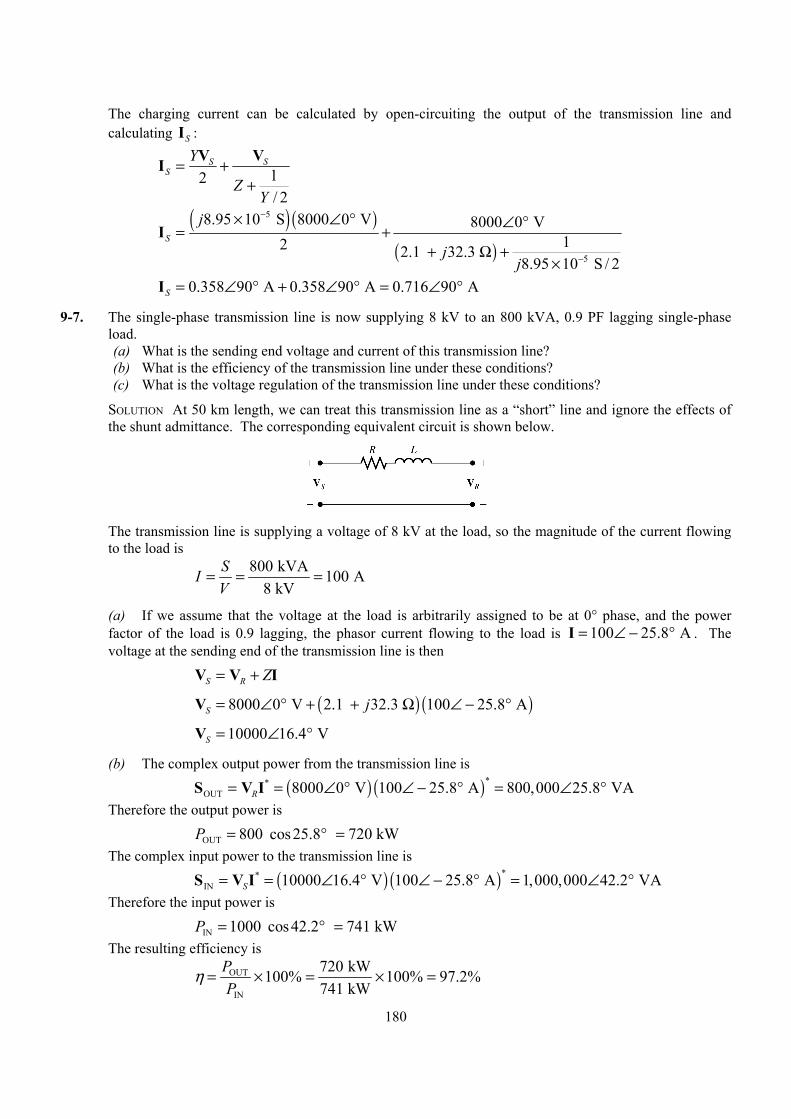
180
The charging current can be calculated by open-circuiting the output of the transmission line and calculating SI :
12/ 2
S SS
Y
ZY
= ++
V VI
( ) ( )
( )
5
5
8.95 10 S 8000 0 V 8000 0 V12 2.1 32.3
8.95 10 S / 2
S
j
jj
−
−
× ∠ ° ∠ °= ++ Ω +
×
I
0.358 90 A 0.358 90 A 0.716 90 AS = ∠ ° + ∠ ° = ∠ °I
9-7. The single-phase transmission line is now supplying 8 kV to an 800 kVA, 0.9 PF lagging single-phase load. (a) What is the sending end voltage and current of this transmission line? (b) What is the efficiency of the transmission line under these conditions? (c) What is the voltage regulation of the transmission line under these conditions?
SOLUTION At 50 km length, we can treat this transmission line as a “short” line and ignore the effects of the shunt admittance. The corresponding equivalent circuit is shown below.
The transmission line is supplying a voltage of 8 kV at the load, so the magnitude of the current flowing
to the load is
800 kVA 100 A8 kV
SIV
= = =
(a) If we assume that the voltage at the load is arbitrarily assigned to be at 0° phase, and the power factor of the load is 0.9 lagging, the phasor current flowing to the load is 100 25.8 A= ∠ − °I . The voltage at the sending end of the transmission line is then
S R Z= +V V I
( ) ( )8000 0 V 2.1 32.3 100 25.8 AS j= ∠ ° + + Ω ∠ − °V
10000 16.4 VS = ∠ °V
(b) The complex output power from the transmission line is
( ) ( )**OUT 8000 0 V 100 25.8 A 800,000 25.8 VAR= = ∠ ° ∠ − ° = ∠ °S V I
Therefore the output power is
OUT 800 cos25.8 720 kWP = ° = The complex input power to the transmission line is
( ) ( )**IN 10000 16.4 V 100 25.8 A 1,000,000 42.2 VAS= = ∠ ° ∠ − ° = ∠ °S V I
Therefore the input power is
IN 1000 cos42.2 741 kWP = ° = The resulting efficiency is
OUT
IN
720 kW100% 100% 97.2%741 kW
PP
η = × = × =
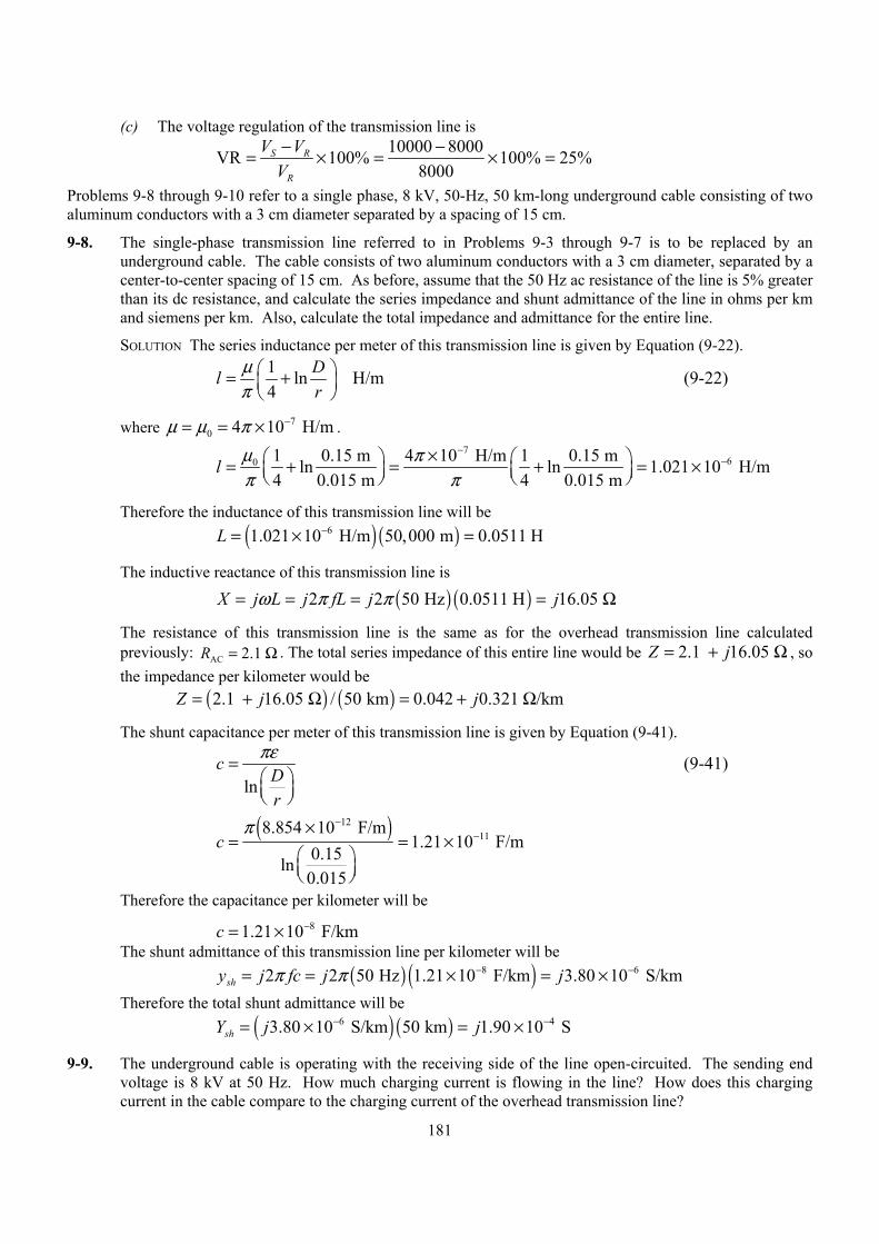
181
(c) The voltage regulation of the transmission line is
10000 8000VR 100% 100% 25%8000
S R
R
V VV− −= × = × =
Problems 9-8 through 9-10 refer to a single phase, 8 kV, 50-Hz, 50 km-long underground cable consisting of two aluminum conductors with a 3 cm diameter separated by a spacing of 15 cm.
9-8. The single-phase transmission line referred to in Problems 9-3 through 9-7 is to be replaced by an underground cable. The cable consists of two aluminum conductors with a 3 cm diameter, separated by a center-to-center spacing of 15 cm. As before, assume that the 50 Hz ac resistance of the line is 5% greater than its dc resistance, and calculate the series impedance and shunt admittance of the line in ohms per km and siemens per km. Also, calculate the total impedance and admittance for the entire line.
SOLUTION The series inductance per meter of this transmission line is given by Equation (9-22).
1 ln H/m4
Dlr
µπ = +
(9-22)
where 70 4 10 H/mµ µ π −= = × .
7
60 1 0.15 m 4 10 H/m 1 0.15 mln ln 1.021 10 H/m4 0.015 m 4 0.015 m
l µ ππ π
−−× = + = + = ×
Therefore the inductance of this transmission line will be ( ) ( )61.021 10 H/m 50,000 m 0.0511 HL −= × =
The inductive reactance of this transmission line is
( ) ( )2 2 50 Hz 0.0511 H 16.05 X j L j fL j jω π π= = = = Ω
The resistance of this transmission line is the same as for the overhead transmission line calculated previously: AC 2.1 R = Ω . The total series impedance of this entire line would be 2.1 16.05 Z j= + Ω , so the impedance per kilometer would be
( ) ( )2.1 16.05 / 50 km 0.042 0.321 /kmZ j j= + Ω = + Ω
The shunt capacitance per meter of this transmission line is given by Equation (9-41).
ln
cDr
πε=
(9-41)
( )12
118.854 10 F/m1.21 10 F/m
0.15ln0.015
cπ −
−×= = ×
Therefore the capacitance per kilometer will be
81.21 10 F/kmc −= × The shunt admittance of this transmission line per kilometer will be ( ) ( )8 62 2 50 Hz 1.21 10 F/km 3.80 10 S/kmshy j fc j jπ π − −= = × = × Therefore the total shunt admittance will be ( ) ( )6 43.80 10 S/km 50 km 1.90 10 SshY j j− −= × = ×
9-9. The underground cable is operating with the receiving side of the line open-circuited. The sending end voltage is 8 kV at 50 Hz. How much charging current is flowing in the line? How does this charging current in the cable compare to the charging current of the overhead transmission line?
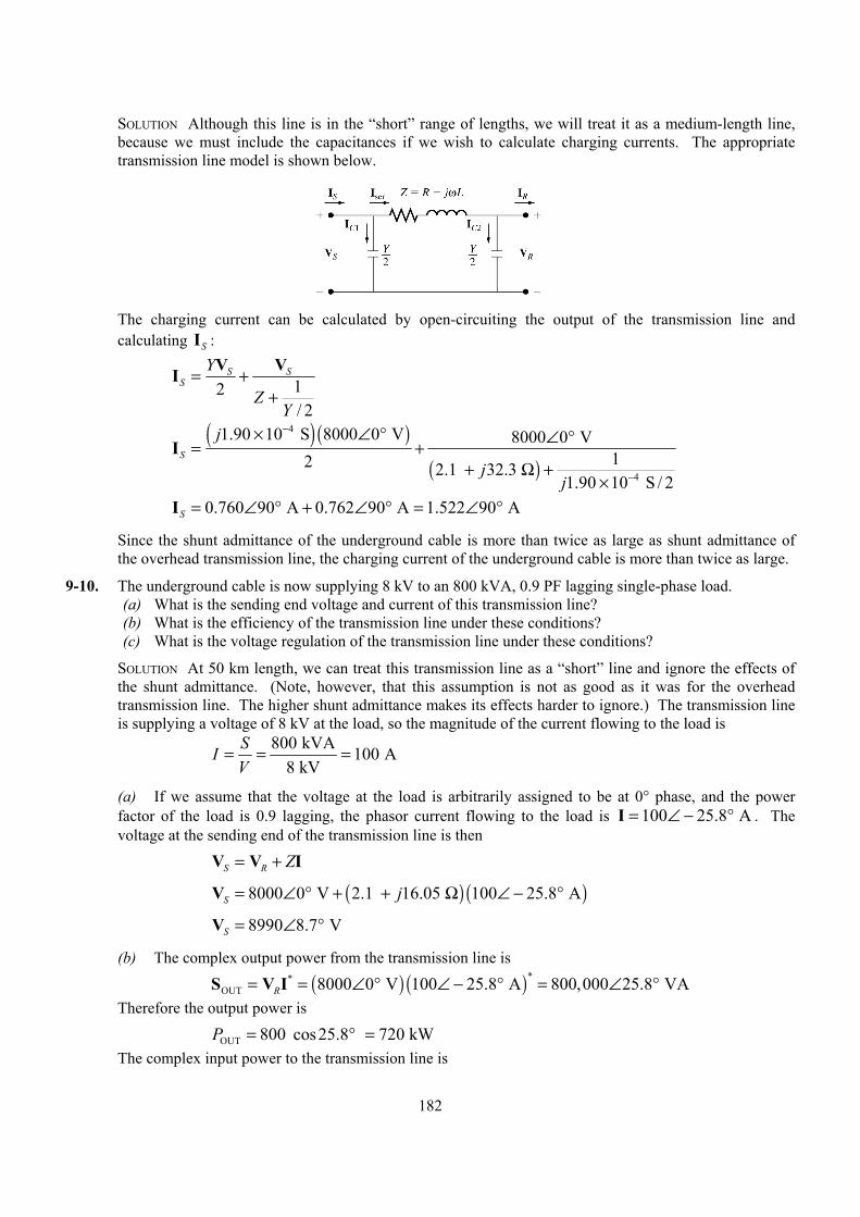
182
SOLUTION Although this line is in the “short” range of lengths, we will treat it as a medium-length line, because we must include the capacitances if we wish to calculate charging currents. The appropriate transmission line model is shown below.
The charging current can be calculated by open-circuiting the output of the transmission line and
calculating SI :
12/ 2
S SS
Y
ZY
= ++
V VI
( ) ( )
( )
4
4
1.90 10 S 8000 0 V 8000 0 V12 2.1 32.3
1.90 10 S / 2
S
j
jj
−
−
× ∠ ° ∠ °= ++ Ω +
×
I
0.760 90 A 0.762 90 A 1.522 90 AS = ∠ ° + ∠ ° = ∠ °I
Since the shunt admittance of the underground cable is more than twice as large as shunt admittance of the overhead transmission line, the charging current of the underground cable is more than twice as large.
9-10. The underground cable is now supplying 8 kV to an 800 kVA, 0.9 PF lagging single-phase load. (a) What is the sending end voltage and current of this transmission line? (b) What is the efficiency of the transmission line under these conditions? (c) What is the voltage regulation of the transmission line under these conditions?
SOLUTION At 50 km length, we can treat this transmission line as a “short” line and ignore the effects of the shunt admittance. (Note, however, that this assumption is not as good as it was for the overhead transmission line. The higher shunt admittance makes its effects harder to ignore.) The transmission line is supplying a voltage of 8 kV at the load, so the magnitude of the current flowing to the load is
800 kVA 100 A8 kV
SIV
= = =
(a) If we assume that the voltage at the load is arbitrarily assigned to be at 0° phase, and the power factor of the load is 0.9 lagging, the phasor current flowing to the load is 100 25.8 A= ∠ − °I . The voltage at the sending end of the transmission line is then
S R Z= +V V I
( ) ( )8000 0 V 2.1 16.05 100 25.8 AS j= ∠ ° + + Ω ∠ − °V
8990 8.7 VS = ∠ °V
(b) The complex output power from the transmission line is
( ) ( )**OUT 8000 0 V 100 25.8 A 800,000 25.8 VAR= = ∠ ° ∠ − ° = ∠ °S V I
Therefore the output power is
OUT 800 cos25.8 720 kWP = ° = The complex input power to the transmission line is
183
( ) ( )**IN 8990 8.7 V 100 25.8 A 899,000 34.5 VAS= = ∠ ° ∠ − ° = ∠ °S V I
Therefore the input power is
IN 899 cos34.5 740.9 kWP = ° = The resulting efficiency is
OUT
IN
720 kW100% 100% 97.2%740.9 kW
PP
η = × = × =
(c) The voltage regulation of the transmission line is
8990 8000VR 100% 100% 12.4%8000
S R
R
V VV− −= × = × =
9-11. A 138 kV, 200 MVA, 60 Hz, three-phase, power transmission line is 100 km long, and has the following characteristics:
r = 0.103 Ω/km
x = 0.525 Ω/km
y = 3.3 × 10⁻⁶ S/km (a) What is per phase series impedance and shunt admittance of this transmission line? (b) Should it be modeled as a short, medium, or long transmission line? (c) Calculate the ABCD constants of this transmission line. (d) Sketch the phasor diagram of this transmission line when the line is supplying rated voltage and
apparent power at a 0.90 power factor lagging. (e) Calculate the sending end voltage if the line is supplying rated voltage and apparent power at 0.90
PF lagging. (f) What is the voltage regulation of the transmission line for the conditions in (e)? (g) What is the efficiency of the transmission line for the conditions in (e)?
SOLUTION
(a) The per-phase series impedance of this transmission line is
( ) ( )0.103 0.525 /km 100 km 10.3 52.5 Z j j= + Ω = + Ω
The per-phase shunt admittance of this transmission line is ( ) ( )63.3 10 S/km 100 km 0.00033 SY j j−= × =
(b) This transmission line should be modeled as a medium length transmission line.
(c) The ABCD constants for a medium length line are given by the following equations:
1
2
1 14 2
ZYA B Z
ZY ZYC Y D
= + =
= + = +
(9-73)
( ) ( )10.3 52.5 0.00033 S1 1 0.9913 0.1
2 2j jZYA
+ Ω= + = + = ∠ °
10.3 52.5 53.5 78.9 B Z j= = + Ω = ∠ ° Ω
( ) ( ) ( )10.3 52.5 0.00033 S1 0.00033 S 1
4 4j jZYC Y j
+ Ω = + = +
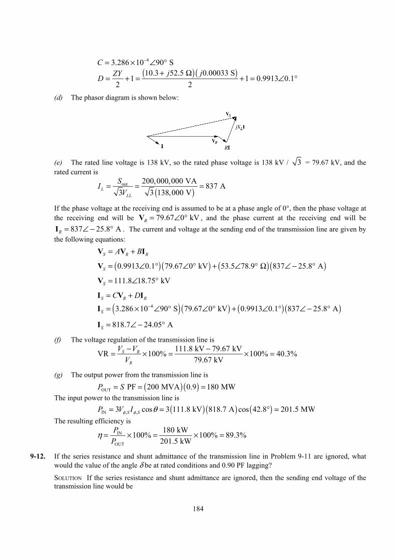
184
43.286 10 90 SC −= × ∠ °
( ) ( )10.3 52.5 0.00033 S1 1 0.9913 0.1
2 2j jZYD
+ Ω= + = + = ∠ °
(d) The phasor diagram is shown below:
(e) The rated line voltage is 138 kV, so the rated phase voltage is 138 kV / 3 = 79.67 kV, and the rated current is
( )
out 200,000,000 VA 837 A3 3 138,000 VL
LL
SIV
= = =
If the phase voltage at the receiving end is assumed to be at a phase angle of 0°, then the phase voltage at the receiving end will be 79.67 0 kVR = ∠ °V , and the phase current at the receiving end will be
837 25.8 AR = ∠ − °I . The current and voltage at the sending end of the transmission line are given by the following equations:
S R RA B= +V V I
( ) ( ) ( ) ( )0.9913 0.1 79.67 0 kV 53.5 78.9 837 25.8 AS = ∠ ° ∠ ° + ∠ ° Ω ∠ − °V
111.8 18.75 kVS = ∠ °V
S R RC D= +I V I
( ) ( ) ( ) ( )43.286 10 90 S 79.67 0 kV 0.9913 0.1 837 25.8 AS−= × ∠ ° ∠ ° + ∠ ° ∠ − °I
818.7 24.05 AS = ∠ − °I
(f) The voltage regulation of the transmission line is
111.8 kV 79.67 kVVR 100% 100% 40.3%79.67 kV
S R
R
V VV− −= × = × =
(g) The output power from the transmission line is
( ) ( )OUT PF 200 MVA 0.9 180 MWP S= = = The input power to the transmission line is ( ) ( ) ( )IN , ,3 cos 3 111.8 kV 818.7 A cos 42.8 201.5 MWS SP V Iφ φ θ= = ° = The resulting efficiency is
IN
OUT
180 kW100% 100% 89.3%201.5 kW
PP
η = × = × =
9-12. If the series resistance and shunt admittance of the transmission line in Problem 9-11 are ignored, what would the value of the angle δ be at rated conditions and 0.90 PF lagging?
SOLUTION If the series resistance and shunt admittance are ignored, then the sending end voltage of the transmission line would be
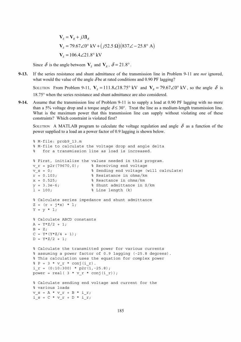
185
S R RjX= +V V I
( ) ( )79.67 0 kV 52.5 837 25.8 AS j= ∠ ° + Ω ∠ − °V
106.4 21.8 kVS = ∠ °V
Since δ is the angle between SV and RV , 21.8δ = ° .
9-13. If the series resistance and shunt admittance of the transmission line in Problem 9-11 are not ignored, what would the value of the angle δ be at rated conditions and 0.90 PF lagging?
SOLUTION From Problem 9-11, 111.8 18.75 kVS = ∠ °V and 79.67 0 kVR = ∠ °V , so the angle δ is 18.75° when the series resistance and shunt admittance are also considered.
9-14. Assume that the transmission line of Problem 9-11 is to supply a load at 0.90 PF lagging with no more than a 5% voltage drop and a torque angle δ ≤ 30°. Treat the line as a medium-length transmission line. What is the maximum power that this transmission line can supply without violating one of these constraints? Which constraint is violated first?
SOLUTION A MATLAB program to calculate the voltage regulation and angle δ as a function of the power supplied to a load an a power factor of 0.9 lagging is shown below.
% M-file: prob9_13.m% M-file to calculate the voltage drop and angle delta% for a transmission line as load is increased.
% First, initialize the values needed in this program.v_r = p2r(79670,0); % Receiving end voltagev_s = 0; % Sending end voltage (will calculate)r = 0.103; % Resistance in ohms/kmx = 0.525; % Reactance in ohms/kmy = 3.3e-6; % Shunt admittance in S/kml = 100; % Line length (k)
% Calculate series impedance and shunt admittanceZ = (r + j*x) * l;Y = y * l;
% Calculate ABCD constantsA = Y*Z/2 + 1;B = Z;C = Y*(Y*Z/4 + 1);D = Y*Z/2 + 1;
% Calculate the transmitted power for various currents% assuming a power factor of 0.9 lagging (-25.8 degrees).% This calculation uses the equation for complex power% P = 3 * v_r * conj(i_r).i_r = (0:10:300) * p2r(1,-25.8);power = real( 3 * v_r * conj(i_r));
% Calculate sending end voltage and current for the% various loadsv_s = A * v_r + B * i_r;i_s = C * v_r + D * i_r;

186
% Calculate VR for each current stepVR = ( abs(v_s) - abs(v_r) ) ./ abs(v_r);
% Calculate angle delta for each current step[v_r_mag, v_r_angle] = r2p(v_r);for ii = 1:length(i_r)
[v_s_mag, v_s_angle] = r2p(v_s(ii));delta(ii) = v_s_angle - v_r_angle;
end
% Which limit is reached first?for ii = 1:length(i_r)
if VR(ii) > 0.05
% VR exceeded first--tell userstr = ['VR exceeds 5% at ' num2str(power(ii)/1e6) ' MW'];disp(str);break;
elseif abs(delta) > 30
% Delta exceeded first--tell userstr = ['delta exceeds 30 deg at ' num2str(power(ii)/1e6) ' MW'];disp(str);break;
endend
% Plot the VR and delta vs powerfigure(1);plot(power/1e6,VR*100,'b-','LineWidth',2.0);xlabel('\bfPower (MW)');ylabel('\bfVoltage Regulation (%)');title ('\bfVoltage Regulation vs Power Supplied');grid on;
figure(2);plot(power/1e6,delta,'b-','LineWidth',2.0);xlabel('\bfPower (MW)');ylabel('\bfAngle \delta (deg)');title ('\bfAngle \delta vs Power Supplied');grid on;
When this program is executed, the results are as shown below. Note that the voltage regulation is the first limit to be exceeded by this transmission line of the load is at 0.9 PF lagging. Try the same calculation with other power factors. How does the maximum power supplied vary?
>> prob9_13VR exceeds 5% at 25.8222 MW
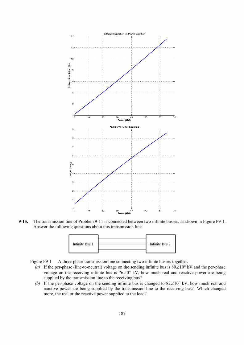
187
9-15. The transmission line of Problem 9-11 is connected between two infinite busses, as shown in Figure P9-1.
Answer the following questions about this transmission line.
Infinite Bus 1 Infinite Bus 2
Figure P9-1 A three-phase transmission line connecting two infinite busses together. (a) If the per-phase (line-to-neutral) voltage on the sending infinite bus is 80∠10° kV and the per-phase
voltage on the receiving infinite bus is 76∠0° kV, how much real and reactive power are being supplied by the transmission line to the receiving bus?
(b) If the per-phase voltage on the sending infinite bus is changed to 82∠10° kV, how much real and reactive power are being supplied by the transmission line to the receiving bus? Which changed more, the real or the reactive power supplied to the load?
188
(c) If the per-phase voltage on the sending infinite bus is changed to 80∠15° kV, how much real and reactive power are being supplied by the transmission line to the receiving bus? Compared to the conditions in part (a), which changed more, the real or the reactive power supplied to the load?
(d) From the above results, how could real power flow be controlled in a transmission line? How could reactive power flow be controlled in a transmission line?
SOLUTION
(a) If the shunt admittance of the transmission line is ignored, the relationship between the voltages and currents on this transmission line is
S R R jX= + +V V I I where S R= =I I I . Therefore we can calculate the current in the transmission line as
S R
R jX−=
+V VI
80,000 10 76,000 0 265 0.5 A10.3 52.5 j
∠ ° − ∠ °= = ∠ − °+ Ω
I
The real and reactive power supplied by this transmission line is ( ) ( ) ( ),3 cos 3 76 kV 265 A cos 0.5 60.4 MWRP V Iφ φ θ= = ° =
( ) ( ) ( ),3 sin 3 76 kV 265 A sin 0.5 0.53 MVARRQ V Iφ φ θ= = ° =
(b) If the sending end voltage is changed to 82∠10° kV, the current is
82,000 10 76,000 0 280 7.7 A10.3 52.5 j
∠ ° − ∠ °= = ∠ − °+ Ω
I
The real and reactive power supplied by this transmission line is ( ) ( ) ( ),3 cos 3 76 kV 280 A cos 7.7 63.3 MWRP V Iφ φ θ= = ° =
( ) ( ) ( ),3 sin 3 76 kV 280 A sin 7.7 8.56 MVARRQ V Iφ φ θ= = ° =
In this case, there was a relatively small change in P (3 MW) and a relatively large change in Q (8 MVAR) supplied to the receiving bus.
(c) If the sending end voltage is changed to 82∠10° kV, the current is
80,000 15 76,000 0 388 7.2 A10.3 52.5 j
∠ ° − ∠ °= = ∠ °+ Ω
I
The real and reactive power supplied by this transmission line is ( ) ( ) ( ),3 cos 3 76 kV 388 A cos 7.2 87.8 MWRP V Iφ φ θ= = − ° =
( ) ( ) ( ),3 sin 3 76 kV 388 A sin 7.2 11 MVARRQ V Iφ φ θ= = − ° = −
In this case, there was a relatively large change in P (27.4 MW) and a relatively small change in Q (11.5 MVAR) supplied to the receiving bus.
(d) From the above results, we can see that real power flow can be adjusted by changing the phase angle between the two voltages at the two ends of the transmission line, while reactive power flow can be changed by changing the relative magnitude of the two voltages on either side of the transmission line.
9-16. A 50 Hz three phase transmission line is 300 km long. It has a total series impedance of 23 75 j+ Ω and a shunt admittance of 500 Sj µ . It delivers 150 MW at 220 kV, with a power factor of 0.88 lagging. Find the voltage at the sending end using (a) the short line approximation. (b) The medium-length line
189
approximation. (c) The long line equation. How accurate are the short and medium-length line approximations for this case?
SOLUTION
(a) In the short line approximation, the shunt admittance is ignored. The ABCD constants for this line are:
10 1
A B ZC D
= == =
(9-67)
1A = 23 75 78.4 73 B Z j= = + Ω = ∠ ° Ω
0 SC =
1D =
The receiving end line voltage is 220 kV, so the rated phase voltage is 220 kV / 3 = 127 kV, and the current is
( )
out 150,000,000 W 394 A3 3 220,000 VL
LL
SIV
= = =
If the phase voltage at the receiving end is assumed to be at a phase angle of 0°, then the phase voltage at the receiving end will be 127 0 kVR = ∠ °V , and the phase current at the receiving end will be
394 28.4 AR = ∠ − °I . The current and voltage at the sending end of the transmission line are given by the following equations:
S R RA B= +V V I
( ) ( ) ( ) ( )1 127 0 kV 78.4 73 394 28.4 AS = ∠ ° + ∠ ° Ω ∠ − °V
151 8.2 kVS = ∠ °V
S R RC D= +I V I
( ) ( ) ( ) ( )0 S 133 0 kV 1 394 28.4 AS = ∠ ° + ∠ − °I
394 28.4 AS = ∠ − °I
(b) In the medium length line approximation, the shunt admittance divided into two equal pieces at either end of the line. The ABCD constants for this line are:
1
2
1 14 2
ZYA B Z
ZY ZYC Y D
= + =
= + = +
(9-73)
( ) ( )23 75 0.0005 S1 1 0.9813 0.34
2 2j jZYA
+ Ω= + = + = ∠ °
23 75 78.4 73 B Z j= = + Ω = ∠ ° Ω
( ) ( ) ( )23 75 0.0005 S1 0.0005 S 1
4 4j jZYC Y j
+ Ω = + = +
190
44.953 10 90.2 SC −= × ∠ °
( ) ( )23 75 0.0005 S1 1 0.9813 0.34
2 2j jZYD
+ Ω= + = + = ∠ °
The receiving end line voltage is 220 kV, so the rated phase voltage is 220 kV / 3 = 127 kV, and the current is
( )
out 150,000,000 W 394 A3 3 220,000 VL
LL
SIV
= = =
If the phase voltage at the receiving end is assumed to be at a phase angle of 0°, then the phase voltage at the receiving end will be 127 0 kVR = ∠ °V , and the phase current at the receiving end will be
394 28.4 AR = ∠ − °I . The current and voltage at the sending end of the transmission line are given by the following equations:
S R RA B= +V V I
148.4 8.7 kVS = ∠ °V
S R RC D= +I V I
361 19.2 AS = ∠ − °I
(c) In the long transmission line, the ABCD constants are based on modified impedances and admittances:
sinh dZ Zdγ
γ′ = (9-74)
( )tanh / 2/ 2d
Y Ydγ
γ′ = (9-75)
and the corresponding ABCD constants are
1
2
1 14 2
Z YA B Z
Z Y Z YC Y D
′ ′ ′= + =
′ ′ ′ ′ ′= + = +
(9-76)
The propagation constant of this transmission line is yzγ =
6500 10 S 23 75 0.00066 81.5
300 km 300 kmj jyzγ
− × + Ω = = = ∠ °
( ) ( )0.00066 81.5 300 km 0.198 81.5dγ = ∠ ° = ∠ °
The modified parameters are
( ) ( )sinh 0.198 81.5sinh 23 75 77.9 73 0.198 81.5
dZ Z jdγ
γ∠ °
= = + Ω = ∠ ° Ω′∠ °
( ) 4tanh / 25.01 10 89.9 S
/ 2d
Y Ydγ
γ−= = × ∠ °′
and the ABCD constants are
191
1 0.983 0.332
Z YA ′ ′= + = ∠ °
77.9 73 B Z= = ∠ ° Ω′
1 4.97 90.1 S4
Z YC Y ′ ′ = + = ∠ °′
1 0.983 0.332
Z YD ′ ′= + = ∠ °
The receiving end line voltage is 220 kV, so the rated phase voltage is 220 kV / 3 = 127 kV, and the current is
( )
out 150,000,000 W 394 A3 3 220,000 VL
LL
SIV
= = =
If the phase voltage at the receiving end is assumed to be at a phase angle of 0°, then the phase voltage at the receiving end will be 127 0 kVR = ∠ °V , and the phase current at the receiving end will be
394 28.4 AR = ∠ − °I . The current and voltage at the sending end of the transmission line are given by the following equations:
S R RA B= +V V I
148.2 8.7 kVS = ∠ °V
S R RC D= +I V I
361.2 19.2 AS = ∠ − °I
The short transmission line approximate was rather inaccurate, but the medium and long line models were both in good agreement with each other.
9-17. A 60 Hz, three phase, 110 kV transmission line has a length of 100 miles and a series impedance of 0.20 0.85j+ Ω/mile and a shunt admittance of 66 10−× S/mile. The transmission line is supplying 60 MW at a power factor of 0.85 lagging, and the receiving end voltage is 110 kV. (a) What are the voltage, current, and power factor at the receiving end of this line? (b) What are the voltage, current, and power factor at the sending end of this line? (c) How much power is being lost in this transmission line? (d) What is the current angle δ of this transmission line? How close is the transmission line to its
steady-state stability limit?
SOLUTION This transmission line may be considered to be a medium-line line. The impedance Z and admittance Y of this line are:
( ) ( )0.20 0.85 /mile 100 miles 20 85 Z j j= + Ω = + Ω
( ) ( )66 10 /mile 100 miles 0.0006 SY j j−= × =
The ABCD constants for this line are:
( ) ( )20 85 0.0006 S1 1 0.9745 0.35
2 2j jZYA
+ Ω= + = + = ∠ °
20 85 87.3 76.8 B Z j= = + Ω = ∠ ° Ω
( ) ( ) ( )20 85 0.0006 S1 0.0006 S 1 0.00059 90.2 S
4 4j jZYC Y j
+ Ω = + = + = ∠ °
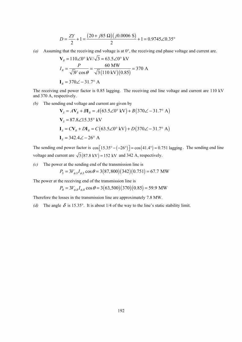
192
( ) ( )20 85 0.0006 S1 1 0.9745 0.35
2 2j jZYD
+ Ω= + = + = ∠ °
(a) Assuming that the receiving end voltage is at 0°, the receiving end phase voltage and current are.
110 0 kV/ 3 63.5 0 kVR = ∠ ° = ∠ °V
( ) ( )
60 MW 370 A3 cos 3 110 kV 0.85R
PIV θ
= = =
370 31.7 AR = ∠ − °I
The receiving end power factor is 0.85 lagging. The receiving end line voltage and current are 110 kV and 370 A, respectively.
(b) The sending end voltage and current are given by
( ) ( )63.5 0 kV 370 31.7 AS R RA B A B= + = ∠ ° + ∠ − °V V I
87.8 15.35 kVS = ∠ °V
( ) ( )63.5 0 kV 370 31.7 AS R RC D C D= + = ∠ ° + ∠ − °I V I
342.4 26 AS = ∠ − °I
The sending end power factor is ( ) ( )cos 15.35 26 cos 41.4 0.751 lagging ° − − ° = ° = . The sending end line
voltage and current are ( )3 87.8 kV 152 kV= and 342 A, respectively.
(c) The power at the sending end of the transmission line is ( ) ( ) ( ), ,3 cos 3 87,800 342 0.751 67.7 MWS S SP V Iφ φ θ= = =
The power at the receiving end of the transmission line is ( ) ( ) ( ), ,3 cos 3 63,500 370 0.85 59.9 MWR R RP V Iφ φ θ= = =
Therefore the losses in the transmission line are approximately 7.8 MW.
(d) The angle δ is 15.35°. It is about 1/4 of the way to the line’s static stability limit.
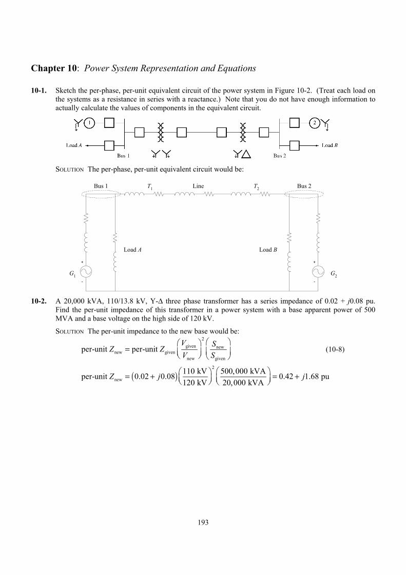
193
Chapter 10: Power System Representation and Equations
10-1. Sketch the per-phase, per-unit equivalent circuit of the power system in Figure 10-2. (Treat each load on the systems as a resistance in series with a reactance.) Note that you do not have enough information to actually calculate the values of components in the equivalent circuit.
SOLUTION The per-phase, per-unit equivalent circuit would be:
+
-
+
-
Load A Load B
G1 G2
LineT1 T2Bus 1 Bus 2
10-2. A 20,000 kVA, 110/13.8 kV, Y-∆ three phase transformer has a series impedance of 0.02 + j0.08 pu.
Find the per-unit impedance of this transformer in a power system with a base apparent power of 500 MVA and a base voltage on the high side of 120 kV.
SOLUTION The per-unit impedance to the new base would be:
2
given newnew given
new given
per-unit per-unit V SZ ZV S
=
(10-8)
( )2
new110 kV 500,000 kVAper-unit 0.02 0.08 0.42 1.68 pu120 kV 20,000 kVA
Z j j = + = +
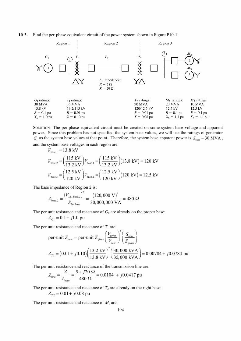
194
10-3. Find the per-phase equivalent circuit of the power system shown in Figure P10-1.
SOLUTION The per-phase equivalent circuit must be created on some system base voltage and apparent
power. Since this problem has not specified the system base values, we will use the ratings of generator 1G as the system base values at that point. Therefore, the system base apparent power is base 30 MVAS = ,
and the system base voltages in each region are: base,1 13.8 kVV =
( )base,2 base,1115 kV 115 kV 13.8 kV 120 kV13.2 kV 13.2 kV
V V = = =
( )base,3 base,212.5 kV 12.5 kV 120 kV 12.5 kV120 kV 120 kV
V V = = =
The base impedance of Region 2 is:
( ) ( )
2 2, base,2
base,2, base
120,000 V480
30,000,000 VALLV
ZS3φ
= = = Ω
The per unit resistance and reactance of G1 are already on the proper base: 1 0.1 1.0 puGZ j= +
The per unit resistance and reactance of T1 are:
2
given newnew given
new given
per-unit per-unit V SZ ZV S
=
( )2
113.2 kV 30,000 kVA0.01 0.10 0.00784 0.0784 pu13.8 kV 35,000 kVATZ j j = + = +
The per unit resistance and reactance of the transmission line are:
linebase
5 20 0.0104 0.0417 pu480
Z jZ jZ
+ Ω= = = +Ω
The per unit resistance and reactance of T2 are already on the right base: 2 0.01 0.08 puTZ j= +
The per unit resistance and reactance of M1 are:
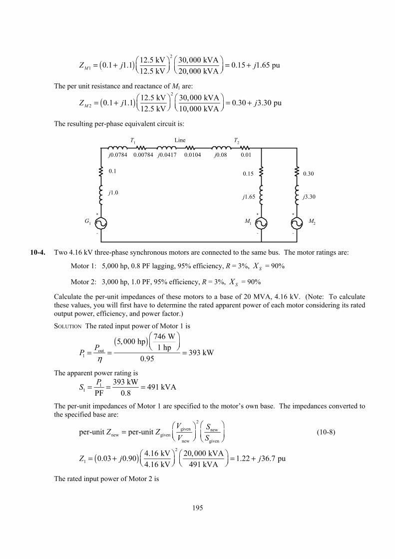
195
( )2
112.5 kV 30,000 kVA0.1 1.1 0.15 1.65 pu12.5 kV 20,000 kVAMZ j j = + = +
The per unit resistance and reactance of M1 are:
( )2
212.5 kV 30,000 kVA0.1 1.1 0.30 3.30 pu12.5 kV 10,000 kVAMZ j j = + = +
The resulting per-phase equivalent circuit is:
+
-
G1 M2
LineT1 T2
+
-
+
-
M1
0.1
j1.0
j0.0784 j0.0417 j0.08
j1.65
0.15
0.00784 0.0104 0.01
j3.30
0.30
10-4. Two 4.16 kV three-phase synchronous motors are connected to the same bus. The motor ratings are:
Motor 1: 5,000 hp, 0.8 PF lagging, 95% efficiency, R = 3%, SX = 90%
Motor 2: 3,000 hp, 1.0 PF, 95% efficiency, R = 3%, SX = 90%
Calculate the per-unit impedances of these motors to a base of 20 MVA, 4.16 kV. (Note: To calculate these values, you will first have to determine the rated apparent power of each motor considering its rated output power, efficiency, and power factor.)
SOLUTION The rated input power of Motor 1 is
( )
out1
746 W5,000 hp1 hp
393 kW0.95
PPη
= = =
The apparent power rating is
11
393 kW 491 kVAPF 0.8PS = = =
The per-unit impedances of Motor 1 are specified to the motor’s own base. The impedances converted to the specified base are:
2
given newnew given
new given
per-unit per-unit V SZ ZV S
=
(10-8)
( )2
14.16 kV 20,000 kVA0.03 0.90 1.22 36.7 pu4.16 kV 491 kVA
Z j j = + = +
The rated input power of Motor 2 is
196
( )
out2
746 W3,000 hp1 hp
236 kW0.95
PPη
= = =
The apparent power rating is
22
236 kW 236 kVAPF 1.0PS = = =
The per-unit impedances of Motor 2 are specified to the motor’s own base. The impedances converted to the specified base are:
2
given newnew given
new given
per-unit per-unit V SZ ZV S
=
(10-8)
( )2
24.16 kV 20,000 kVA0.03 0.90 2.54 76.3 pu4.16 kV 236 kVA
Z j j = + = +
10-5. A Y-connected synchronous generator rated 100 MVA, 13.2 kV has a rated impedance of R = 5% and SX = 80% per-unit. It is connected to a j10 Ω transmission line through a 13.8/120 kV, 100 MVA, ∆-Y
transformer with a rated impedance of R = 2% and X = 8% per unit. The base for the power system is 200 MVA, 120 kV at the transmission line. (a) Sketch the one-line diagram of this power system, with symbols labeled appropriately. (b) Find per-unit impedance of the generator on the system base. (c) Find per-unit impedance of the transformer on the system base. (d) Find per-unit impedance of the transmission line on the system base. (e) Find the per-phase, per-unit equivalent circuit of this power system.
SOLUTION The base quantities for this power system in Region 2 are: base 200 MVAS = base,2 120 kVV =
( ) ( )
2 2, base,2
base,2, base
120,000 V72
200,000,000 VALLV
ZS3φ
= = = Ω
The base quantities for this power system in Region 1 are: base 200 MVAS =
( )base,1 base,213.8 kV 13.8 kV 120 kV 13.8 kV120 kV 120 kV
V V = = =
( ) ( )
2 2, base,1
base,1, base
13,800 V0.952
200,000,000 VALLV
ZS3φ
= = = Ω
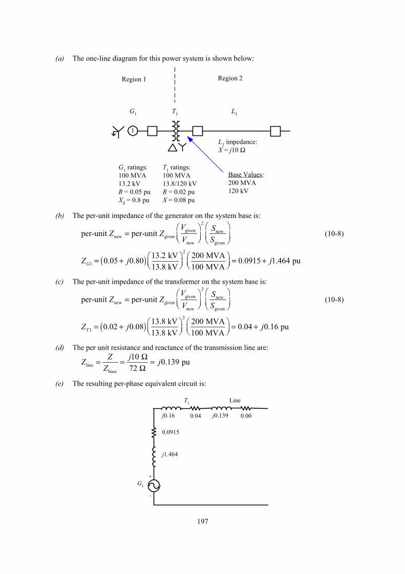
197
(a) The one-line diagram for this power system is shown below:
1
G1 ratings:100 MVA13.2 kVR = 0.05 puXS = 0.8 pu
T1 ratings:100 MVA13.8/120 kVR = 0.02 puX = 0.08 pu
G1 T1
L1 impedance:X = j10 Ω
L1
Region 1 Region 2
Base Values:200 MVA120 kV
(b) The per-unit impedance of the generator on the system base is:
2
given newnew given
new given
per-unit per-unit V SZ ZV S
=
(10-8)
( )2
113.2 kV 200 MVA0.05 0.80 0.0915 1.464 pu13.8 kV 100 MVAGZ j j = + = +
(c) The per-unit impedance of the transformer on the system base is:
2
given newnew given
new given
per-unit per-unit V SZ ZV S
=
(10-8)
( )2
113.8 kV 200 MVA0.02 0.08 0.04 0.16 pu13.8 kV 100 MVATZ j j = + = +
(d) The per unit resistance and reactance of the transmission line are:
linebase
10 0.139 pu72
Z jZ jZ
Ω= = =Ω
(e) The resulting per-phase equivalent circuit is:
+
-
G1
LineT1
0.0915
j1.464
j0.16 j0.1390.04 0.00
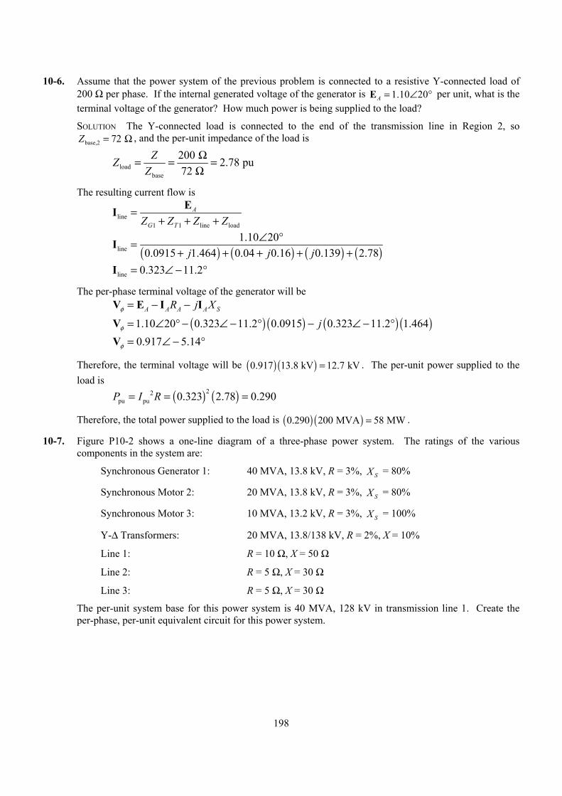
198
10-6. Assume that the power system of the previous problem is connected to a resistive Y-connected load of 200 Ω per phase. If the internal generated voltage of the generator is 1.10 20A = ∠ °E per unit, what is the terminal voltage of the generator? How much power is being supplied to the load?
SOLUTION The Y-connected load is connected to the end of the transmission line in Region 2, so base,2 72 Z = Ω , and the per-unit impedance of the load is
loadbase
200 2.78 pu72
ZZZ
Ω= = =Ω
The resulting current flow is
line1 1 line load
A
G TZ Z Z Z=
+ + +EI
( ) ( ) ( ) ( )line1.10 20
0.0915 1.464 0.04 0.16 0.139 2.78j j j∠ °=
+ + + + +I
line 0.323 11.2= ∠ − °I
The per-phase terminal voltage of the generator will be A A A A SR j Xφ = − −V E I I
( ) ( ) ( ) ( )1.10 20 0.323 11.2 0.0915 0.323 11.2 1.464jφ = ∠ ° − ∠ − ° − ∠ − °V
0.917 5.14φ = ∠ − °V
Therefore, the terminal voltage will be ( ) ( )0.917 13.8 kV 12.7 kV= . The per-unit power supplied to the load is
( ) ( )22pu pu 0.323 2.78 0.290P I R= = =
Therefore, the total power supplied to the load is ( ) ( )0.290 200 MVA 58 MW= .
10-7. Figure P10-2 shows a one-line diagram of a three-phase power system. The ratings of the various components in the system are:
Synchronous Generator 1: 40 MVA, 13.8 kV, R = 3%, SX = 80%
Synchronous Motor 2: 20 MVA, 13.8 kV, R = 3%, SX = 80%
Synchronous Motor 3: 10 MVA, 13.2 kV, R = 3%, SX = 100%
Y-∆ Transformers: 20 MVA, 13.8/138 kV, R = 2%, X = 10%
Line 1: R = 10 Ω, X = 50 Ω
Line 2: R = 5 Ω, X = 30 Ω
Line 3: R = 5 Ω, X = 30 Ω
The per-unit system base for this power system is 40 MVA, 128 kV in transmission line 1. Create the per-phase, per-unit equivalent circuit for this power system.
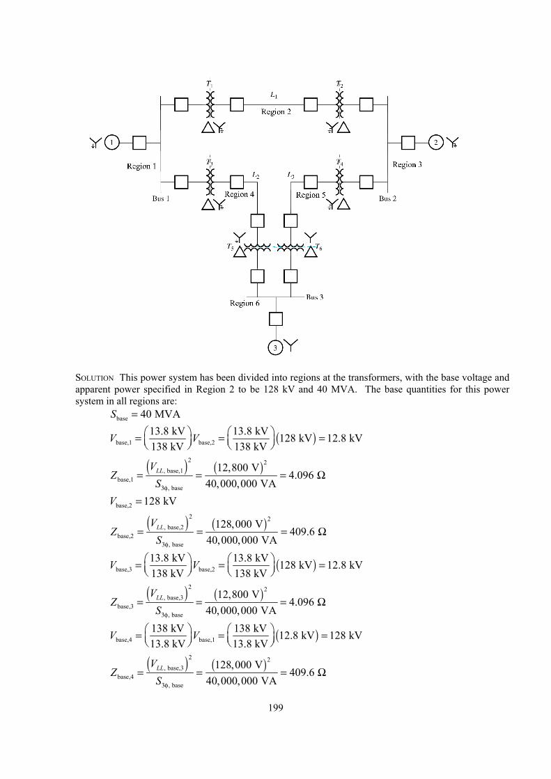
199
SOLUTION This power system has been divided into regions at the transformers, with the base voltage and
apparent power specified in Region 2 to be 128 kV and 40 MVA. The base quantities for this power system in all regions are:
base 40 MVAS =
( )base,1 base,213.8 kV 13.8 kV 128 kV 12.8 kV138 kV 138 kV
V V = = =
( ) ( )
2 2, base,1
base,1, base
12,800 V4.096
40,000,000 VALLV
ZS3φ
= = = Ω
base,2 128 kVV =
( ) ( )
2 2, base,2
base,2, base
128,000 V409.6
40,000,000 VALLV
ZS3φ
= = = Ω
( )base,3 base,213.8 kV 13.8 kV 128 kV 12.8 kV138 kV 138 kV
V V = = =
( ) ( )
2 2, base,3
base,3, base
12,800 V4.096
40,000,000 VALLV
ZS3φ
= = = Ω
( )base,4 base,1138 kV 138 kV 12.8 kV 128 kV13.8 kV 13.8 kV
V V = = =
( ) ( )
2 2, base,3
base,4, base
128,000 V409.6
40,000,000 VALLV
ZS3φ
= = = Ω
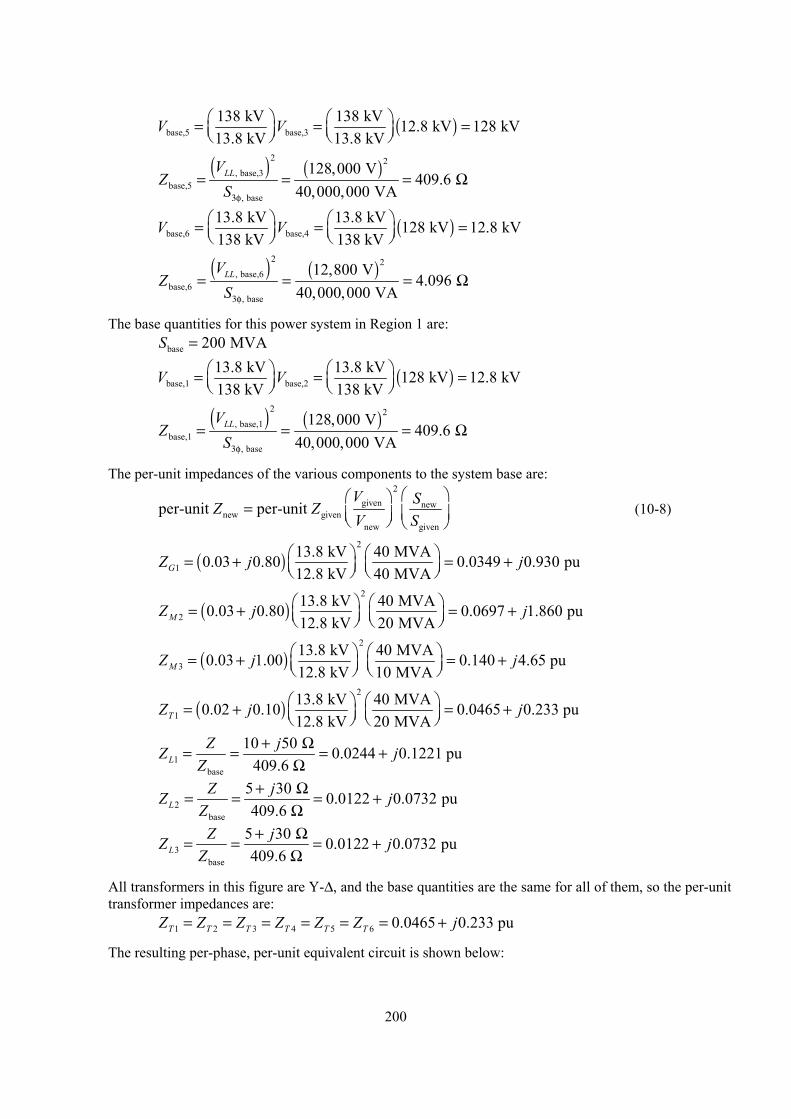
200
( )base,5 base,3138 kV 138 kV 12.8 kV 128 kV13.8 kV 13.8 kV
V V = = =
( ) ( )
2 2, base,3
base,5, base
128,000 V409.6
40,000,000 VALLV
ZS3φ
= = = Ω
( )base,6 base,413.8 kV 13.8 kV 128 kV 12.8 kV138 kV 138 kV
V V = = =
( ) ( )
2 2, base,6
base,6, base
12,800 V4.096
40,000,000 VALLV
ZS3φ
= = = Ω
The base quantities for this power system in Region 1 are: base 200 MVAS =
( )base,1 base,213.8 kV 13.8 kV 128 kV 12.8 kV138 kV 138 kV
V V = = =
( ) ( )
2 2, base,1
base,1, base
128,000 V409.6
40,000,000 VALLV
ZS3φ
= = = Ω
The per-unit impedances of the various components to the system base are:
2
given newnew given
new given
per-unit per-unit V SZ ZV S
=
(10-8)
( )2
113.8 kV 40 MVA0.03 0.80 0.0349 0.930 pu12.8 kV 40 MVAGZ j j = + = +
( )2
213.8 kV 40 MVA0.03 0.80 0.0697 1.860 pu12.8 kV 20 MVAMZ j j = + = +
( )2
313.8 kV 40 MVA0.03 1.00 0.140 4.65 pu12.8 kV 10 MVAMZ j j = + = +
( )2
113.8 kV 40 MVA0.02 0.10 0.0465 0.233 pu12.8 kV 20 MVATZ j j = + = +
1base
10 50 0.0244 0.1221 pu409.6 L
Z jZ jZ
+ Ω= = = +Ω
2base
5 30 0.0122 0.0732 pu409.6 L
Z jZ jZ
+ Ω= = = +Ω
3base
5 30 0.0122 0.0732 pu409.6 L
Z jZ jZ
+ Ω= = = +Ω
All transformers in this figure are Y-∆, and the base quantities are the same for all of them, so the per-unit transformer impedances are:
1 2 3 4 5 6 0.0465 0.233 puT T T T T TZ Z Z Z Z Z j= = = = = = +
The resulting per-phase, per-unit equivalent circuit is shown below:
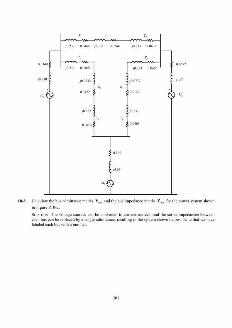
201
+
-
G1
0.0349
j0.930
L1T1
j0.233 j0.1220.0465 0.0244
T2
0.0465j0.233
+
-
M2
0.0697
j1.86
L2
T3
j0.233 0.0465
T4
+
-
M3
T5 T6
L3
0.0465j0.233
0.0122 0.0122
j0.0732 j0.0732
j0.233 j0.233
0.04650.0465
0.140
j4.65
10-8. Calculate the bus admittance matrix busY and the bus impedance matrix busZ for the power system shown
in Figure P10-2.
SOLUTION The voltage sources can be converted to current sources, and the series impedances between each bus can be replaced by a single admittance, resulting in the system shown below. Note that we have labeled each bus with a number.
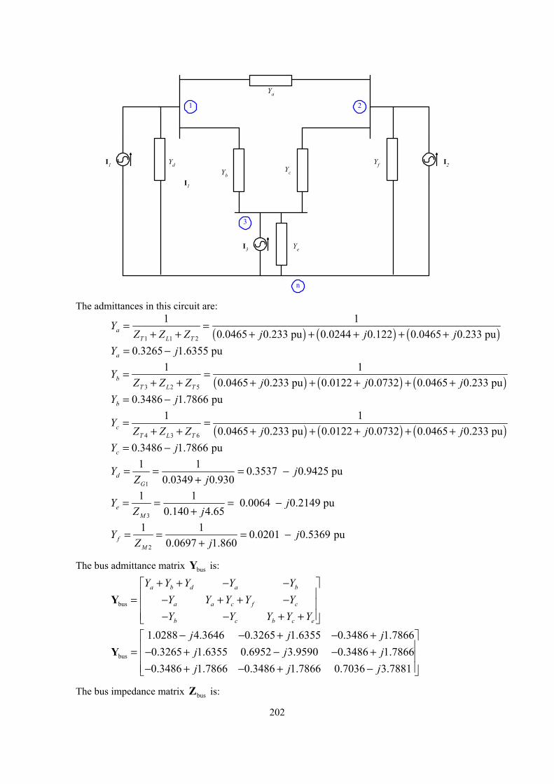
202
Ya
YbYc
Yd
Ye
YfI1
I1
I3
I2
1
n
3
2
The admittances in this circuit are:
( ) ( ) ( )1 1 2
1 10.0465 0.233 pu 0.0244 0.122 0.0465 0.233 pua
T L T
YZ Z Z j j j
= =+ + + + + + +
0.3265 1.6355 puaY j= −
( ) ( ) ( )3 2 5
1 10.0465 0.233 pu 0.0122 0.0732 0.0465 0.233 pub
T L T
YZ Z Z j j j
= =+ + + + + + +
0.3486 1.7866 pubY j= −
( ) ( ) ( )4 3 6
1 10.0465 0.233 pu 0.0122 0.0732 0.0465 0.233 puc
T L T
YZ Z Z j j j
= =+ + + + + + +
0.3486 1.7866 pucY j= −
1
1 1 0.3537 0.9425 pu0.0349 0.930d
G
Y jZ j
= = = −+
3
1 1 0.0064 0.2149 pu0.140 4.65e
M
Y jZ j
= = = −+
2
1 1 0.0201 0.5369 pu0.0697 1.860f
M
Y jZ j
= = = −+
The bus admittance matrix busY is:
bus
a b d a b
a a c f c
b c b c e
Y Y Y Y YY Y Y Y YY Y Y Y Y
+ + − − = − + + − − − + +
Y
bus
1.0288 4.3646 0.3265 1.6355 0.3486 1.78660.3265 1.6355 0.6952 3.9590 0.3486 1.78660.3486 1.7866 0.3486 1.7866 0.7036 3.7881
j j jj j jj j j
− − + − + = − + − − + − + − + −
Y
The bus impedance matrix busZ is:
203
1bus bus
−=Z Y
bus
0.1532 0.6048 0.1068 0.4875 0.1181 0.51720.1068 0.4875 0.1251 0.7046 0.1045 0.56420.1181 0.5172 0.1045 0.5642 0.1479 0.7670
j j jj j jj j j
+ + + = + + + + + +
Z
10-9. Assume that internal generated voltages of the generators and motors in the per-unit equivalent circuit of the previous problem have the following values:
1 1.15 22A = ∠ °E
2 1.00 20A = ∠ − °E
3 0.95 15A = ∠ − °E (a) Find the per-unit voltages on each bus in the power system. (b) Find the actual voltages on each bus in the power system. (c) Find the current flowing in each transmission line in the power system. (d) Determine the magnitude and direction of the real and reactive power flowing in each transmission
line. (e) Are any of the components in the power system overloaded?
SOLUTION The Norton equivalent currents associated with each voltage source are:
11
1
1.15 22 0.7832 0.8526 1.158 47.40.0349 0.930
A
G
jZ j
∠ °= = = − = ∠ − °+
EI
22
2
1.00 20 0.1647 0.5114 0.5373 107.90.0697 1.86
A
M
jZ j
∠ − °= = = − − = ∠ − °+
EI
33
3
0.95 15 0.0469 0.1988 0.204 103.20.14 4.65
A
M
jZ j
∠ − °= = = − − = ∠ − °+
EI
The nodal equations for this power system are: bus =Y V I
11.0288 4.3646 0.3265 1.6355 0.3486 1.7866 0.7832 0.85260.3265 1.6355 0.6952 3.9590 0.3486 1.7866 0.1647 0.51140.3486 1.7866 0.3486 1.7866 0.7036 3.7881 0.0469 0.1988
j j j jj j j jj j j j
−− − + − + − = − + − − + − − − + − + − − −
V
0.9646 0.1604 0.978 9.40.9463 0.0635 0.948 3.80.9503 0.0926 0.955 5.6
jjj
+ ∠ ° = + = ∠ ° + ∠ °
V
(a) The per-unit voltages at each bus in the power system are: 1 0.978 9.4= ∠ °V 2 0.948 3.8= ∠ °V 3 0.955 5.6= ∠ °V
(b) The actual voltages at each bus in the power system are: ( ) ( )1 1,pu base 0.978 12.8 kV 12.5 kVV V V= = =
( ) ( )2 2,pu base 0.948 12.8 kV 12.1 kVV V V= = =
( ) ( )3 3,pu base 0.955 12.8 kV 12.2 kVV V V= = =
204
(c) The current flowing in Line 1 is: (start here) ( ) ( ) ( )1 1 2 0.3265 1.6355 0.978 9.4 0.948 3.8L aY j= − = − ∠ ° − ∠ °I V V
1 0.1645 0.0017 0.165 0.6L j= + = ∠ °I
The current flowing in Line 2 is: ( ) ( ) ( )2 1 3 0.3486 1.7866 0.978 9.4 0.955 5.6L bY j= − = − ∠ ° − ∠ °I V V
2 0.1263 0.0029 0.1269 0.9L j= − = ∠ − °I
The current flowing in Line 3 is: ( ) ( ) ( )3 2 3 0.3486 1.7866 0.948 3.8 0.955 5.6L cY j= − = − ∠ ° − ∠ °I V V
3 0.0533 0.0029 0.0534 177L j= − + = ∠ − °I
(d) The real and reactive power flowing from Bus 1 to Bus 2 in Line 1 is: ( ) ( )**
1 1 1 0.978 9.4 0.165 0.6L L= = ∠ ° ∠ °S V I 1 0.159 0.0248 0.161 8.9L j= + = ∠ °S
( ) ( )1 base 1,pu 40 MVA 0.159 6.4 MWL LP S P= = =
( ) ( )1 base 1,pu 40 MVA 0.0248 1.0 MVARL LQ S Q= = =
The real and reactive power flowing from Bus 1 to Bus 3 in Line 2 is: ( ) ( )**
2 1 2 0.978 9.4 0.1269 0.9L L= = ∠ ° ∠ − °S V I 2 0.1215 0.0221 0.124 10.3L j= + = ∠ °S
( ) ( )2 base 2,pu 40 MVA 0.1215 4.86 MWL LP S P= = =
( ) ( )2 base 2,pu 40 MVA 0.0221 0.88 MVARL LQ S Q= = =
The real and reactive power flowing from Bus 2 to Bus 3 in Line 3 is: ( ) ( )**
3 3 3 0.955 5.6 0.0534 177L L= = ∠ ° ∠ − °S V I 3 0.0509 0.0021 0.051 178L j= − − = ∠ − °S
( ) ( )3 base 3,pu 40 MVA 0.0509 2.04 MWL LP S P= = − = −
( ) ( )3 base 3,pu 40 MVA 0.0021 0.09 MVARL LQ S Q= = − = −
The negative power here means that the power is really flowing from Bus 3 to Bus 2.
(e) None of the components in the power system are even close to being overloaded.
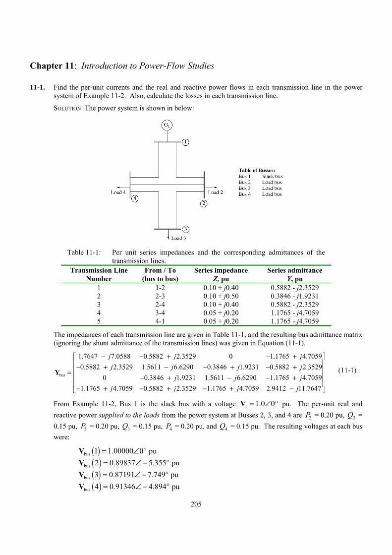
205
Chapter 11: Introduction to Power-Flow Studies
11-1. Find the per-unit currents and the real and reactive power flows in each transmission line in the power system of Example 11-2. Also, calculate the losses in each transmission line.
SOLUTION The power system is shown in below:
Table 11-1: Per unit series impedances and the corresponding admittances of the
transmission lines. Transmission Line
Number From / To
(bus to bus) Series impedance
Z, pu Series admittance
Y, pu 1 1-2 0.10 + j0.40 0.5882 - j2.3529 2 2-3 0.10 + j0.50 0.3846 - j1.9231 3 2-4 0.10 + j0.40 0.5882 - j2.3529 4 3-4 0.05 + j0.20 1.1765 - j4.7059 5 4-1 0.05 + j0.20 1.1765 - j4.7059
The impedances of each transmission line are given in Table 11-1, and the resulting bus admittance matrix (ignoring the shunt admittance of the transmission lines) was given in Equation (11-1).
bus
1.7647 7.0588 0.5882 2.3529 0 1.1765 4.70590.5882 2.3529 1.5611 6.6290 0.3846 1.9231 0.5882 2.3529
0 0.3846 1.9231 1.5611 6.6290 1.1765 4.70591.1765 4.7059 0.5882
j j jj j j j
j j jj
− − + − +− + − − + − +
=− + − − +
− + − +
Y
2.3529 1.1765 4.7059 2.9412 11.7647j j j
− + −
(11-1)
From Example 11-2, Bus 1 is the slack bus with a voltage 1 1.0 0= ∠ °V pu. The per-unit real and reactive power supplied to the loads from the power system at Busses 2, 3, and 4 are 2P = 0.20 pu, 2Q = 0.15 pu, 3P = 0.20 pu, 3Q = 0.15 pu, 4P = 0.20 pu, and 4Q = 0.15 pu. The resulting voltages at each bus were:
( )( )( )( )
bus
bus
bus
bus
1 1.00000 0 pu2 0.89837 5.355 pu3 0.87191 7.749 pu4 0.91346 4.894 pu
= ∠ °= ∠ − °= ∠ − °= ∠ − °
VVVV
206
The per-unit current flowing in transmission lines can be calculated from the following equations
( )1 2Line 1
Line 1
1.00000 0 0.89837 5.355 0.3269 37.50.10 0.40Z j
− ∠ ° − ∠ − °= = = ∠ − °+
V VI
( )2 3Line 2
Line 2
0.89837 5.355 0.87191 7.749 0.0892 30.80.10 0.50Z j
− ∠ − ° − ∠ − °= = = ∠ − °+
V VI
( )2 4Line 3
Line 3
0.89837 5.355 0.91346 4.894 0.0406 124.70.10 0.40Z j
− ∠ − ° − ∠ − °= = = ∠ °+
V VI
( )3 4Line 4
Line 4
0.87191 7.749 0.91346 4.894 0.2952 144.70.05 0.20Z j
− ∠ − ° − ∠ − °= = = ∠ °+
V VI
( )4 1Line 5
Line 5
0.91346 4.894 1.00000 0 0.5770 145.00.05 0.20Z j
− ∠ − ° − ∠ °= = = ∠ °+
V VI
The per-unit power flows entering each transmission line are:
( ) ( )**Line 1 1 Line 1 1.00000 0 0.3269 37.5 0.2594 0.1990j= = ∠ ° ∠ − ° = +S V I
Line 1 0.2594 puP = Line 1 0.1990 puQ =
( ) ( )**Line 2 2 Line 2 0.89837 5.355 0.0892 30.8 0.0723 0.0344j= = ∠ − ° ∠ − ° = +S V I
Line 2 0.0723 puP = Line 2 0.0344 puQ =
( ) ( )**Line 3 2 Line 3 0.89837 5.355 0.0406 124.7 0.0235 0.0280j= = ∠ − ° ∠ ° = − −S V I
Line 3 0.0235 puP = − Line 3 0.0280 puQ = −
( ) ( )**Line 4 3 Line 4 0.87191 7.749 0.2952 144.7 0.2281 0.1192j= = ∠ − ° ∠ ° = − −S V I
Line 4 0.2281 puP = − Line 4 0.1192 puQ = −
( ) ( )**Line 5 4 Line 5 0.91346 4.894 pu 0.5770 145.0 0.4558 0.2647j= = ∠ − ° ∠ ° = − −S V I
Line 5 0.4558 puP = − Line 5 0.2647 puQ = −
The losses in each transmission line are:
( ) ( )22Loss 1 Line 1 Line 1 0.3269 0.1 0.0107 puP I R= = =
( ) ( )22Loss 2 Line 2 Line 2 0.0892 0.1 0.0008 puP I R= = =
( ) ( )22Loss 3 Line 3 Line 3 0.0406 0.1 0.00016 puP I R= = =
( ) ( )22Loss 4 Line 4 Line 4 0.2952 0.05 0.0044 puP I R= = =
207
( ) ( )22Loss 5 Line 5 Line 5 0.5770 0.05 0.0166 puP I R= = =
11-2. Assume that a capacitor bank is added to Bus 4 in the power system of Example 11-2. The capacitor bank consumes a reactive power of cap 0.25 puQ = − , or alternately, the capacitor supplies a reactive power of +0.25 pu to Bus 4. Determine the per-unit bus voltages in the power system after the capacitor is added.
SOLUTION The MATLAB program given in Example 11-2 can be modified by adding the capacitive load to Bus 4, and re-running the program. The modified program is shown below:
% M-file: prob11_2.m% M-file to solve the power-flow problem of Problem 11-2.% This is a modification of the program used to solve% Example 11-2.
% Set problem size and initial conditionsn_bus = 4;swing_bus = 1;
% Create Y-busYbus = ...[ 1.7647-j*7.0588 -0.5882+j*2.3529 0 -1.1765+j*4.7059; ...-0.5882+j*2.3529 1.5611-j*6.6290 -0.3846+j*1.9231 -0.5882+j*2.3529; ...0 -0.3846+j*1.9231 1.5611-j*6.6290 -1.1765+j*4.7059; ...-1.1765+j*4.7059 -0.5882+j*2.3529 -1.1765+j*4.7059 2.9412-j*11.7647 ];
% Initialize the real and reactive power supplied to the% power system at each bus. Note that the power at the% swing bus doesn't matter.P(2) = -0.2;P(3) = -0.3;P(4) = -0.2;Q(2) = -0.15;Q(3) = -0.15;Q(4) = -0.10+0.25; % This is the modified line!
% Initialize the bus voltages to 1.0 at 0 degreesfor ii = 1:n_bus
Vbus(ii) = 1;end
% Set convergence criterioneps = 0.0001;
% Initialize the iteration countern_iter = 0;
% Create an infinite loopwhile (1)
% Increment the iteration countn_iter = n_iter + 1;
% Save old bus voltages for comparison purposesVbus_old = Vbus;

208
% Calculate the updated bus voltagefor ii = 1:n_bus
% Skip the slack bus!if ii ~= swing_bus
% Calculate updated voltage at bus 'ii'. First, sum% up the current contributions at bus 'ii' from all% other busses.temp = 0;for jj = 1:n_bus
if ii ~= jjtemp = temp - Ybus(ii,jj) * Vbus_old(jj);
endend
% Add in the current injected at this nodetemp = (P(ii) - j*Q(ii)) / conj(Vbus_old(ii)) + temp;
% Get updated estimate of Vbus at 'ii'Vbus(ii) = 1/Ybus(ii,ii) * temp;
endend
% Compare the old and new estimate of the voltages.% Note that we will compare the real and the imag parts% separately, and both must be within tolerances.test = 0;for ii = 1:n_bus
% Compare real partsif abs( real(Vbus(ii)) - real(Vbus_old(ii)) ) > eps
test = 1;end
% Compare imaginary partsif abs( imag(Vbus(ii)) - imag(Vbus_old(ii)) ) > eps
test = 1;end
end
% Did we converge? If so, get out of the loop.if test == 0
break;end
end
% Display resultsfor ii = 1:n_bus
[mag, phase] = r2p(Vbus(ii));str = ['The voltage at bus ' int2str(ii) ' = ' ...
num2str(mag) '/' num2str(phase)];disp(str);
end
% Display the number of iterations
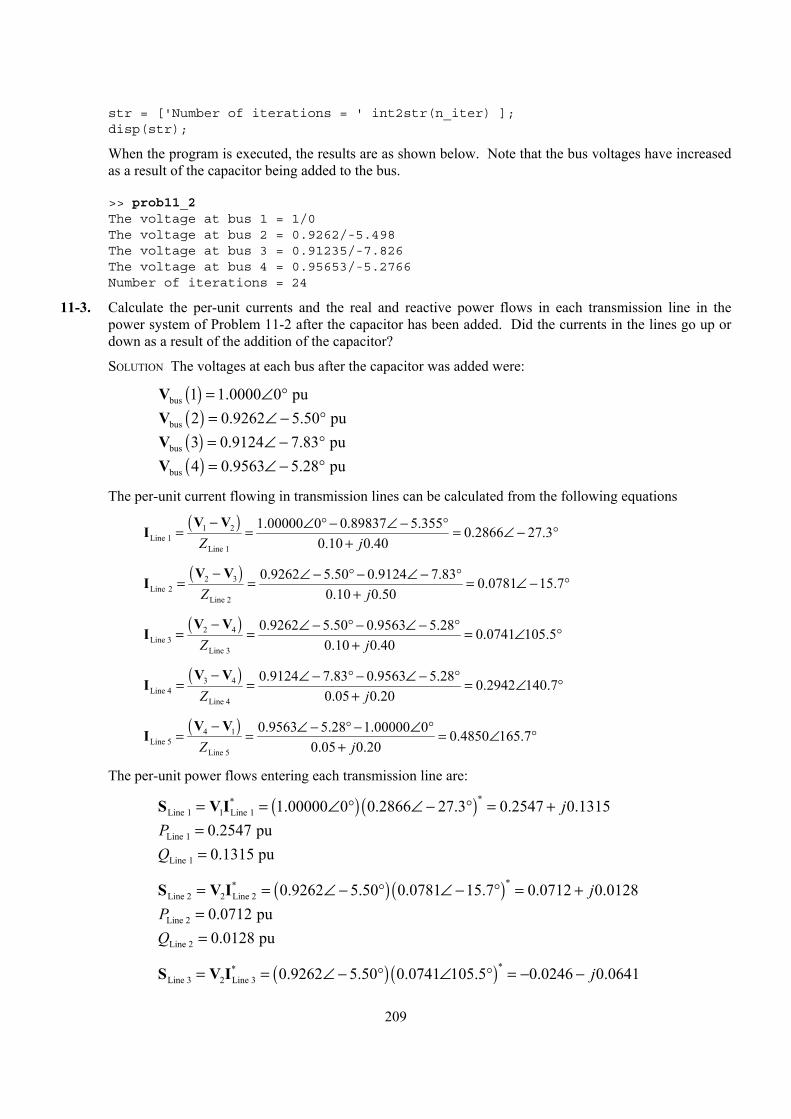
209
str = ['Number of iterations = ' int2str(n_iter) ];disp(str);
When the program is executed, the results are as shown below. Note that the bus voltages have increased as a result of the capacitor being added to the bus.
>> prob11_2The voltage at bus 1 = 1/0The voltage at bus 2 = 0.9262/-5.498The voltage at bus 3 = 0.91235/-7.826The voltage at bus 4 = 0.95653/-5.2766Number of iterations = 24
11-3. Calculate the per-unit currents and the real and reactive power flows in each transmission line in the power system of Problem 11-2 after the capacitor has been added. Did the currents in the lines go up or down as a result of the addition of the capacitor?
SOLUTION The voltages at each bus after the capacitor was added were:
( )( )( )( )
bus
bus
bus
bus
1 1.0000 0 pu2 0.9262 5.50 pu3 0.9124 7.83 pu4 0.9563 5.28 pu
= ∠ °= ∠ − °= ∠ − °= ∠ − °
VVVV
The per-unit current flowing in transmission lines can be calculated from the following equations
( )1 2Line 1
Line 1
1.00000 0 0.89837 5.355 0.2866 27.30.10 0.40Z j
− ∠ ° − ∠ − °= = = ∠ − °+
V VI
( )2 3Line 2
Line 2
0.9262 5.50 0.9124 7.83 0.0781 15.70.10 0.50Z j
− ∠ − ° − ∠ − °= = = ∠ − °+
V VI
( )2 4Line 3
Line 3
0.9262 5.50 0.9563 5.28 0.0741 105.50.10 0.40Z j
− ∠ − ° − ∠ − °= = = ∠ °+
V VI
( )3 4Line 4
Line 4
0.9124 7.83 0.9563 5.28 0.2942 140.70.05 0.20Z j
− ∠ − ° − ∠ − °= = = ∠ °+
V VI
( )4 1Line 5
Line 5
0.9563 5.28 1.00000 0 0.4850 165.70.05 0.20Z j
− ∠ − ° − ∠ °= = = ∠ °+
V VI
The per-unit power flows entering each transmission line are:
( ) ( )**Line 1 1 Line 1 1.00000 0 0.2866 27.3 0.2547 0.1315j= = ∠ ° ∠ − ° = +S V I
Line 1 0.2547 puP = Line 1 0.1315 puQ =
( ) ( )**Line 2 2 Line 2 0.9262 5.50 0.0781 15.7 0.0712 0.0128j= = ∠ − ° ∠ − ° = +S V I
Line 2 0.0712 puP = Line 2 0.0128 puQ =
( ) ( )**Line 3 2 Line 3 0.9262 5.50 0.0741 105.5 0.0246 0.0641j= = ∠ − ° ∠ ° = − −S V I
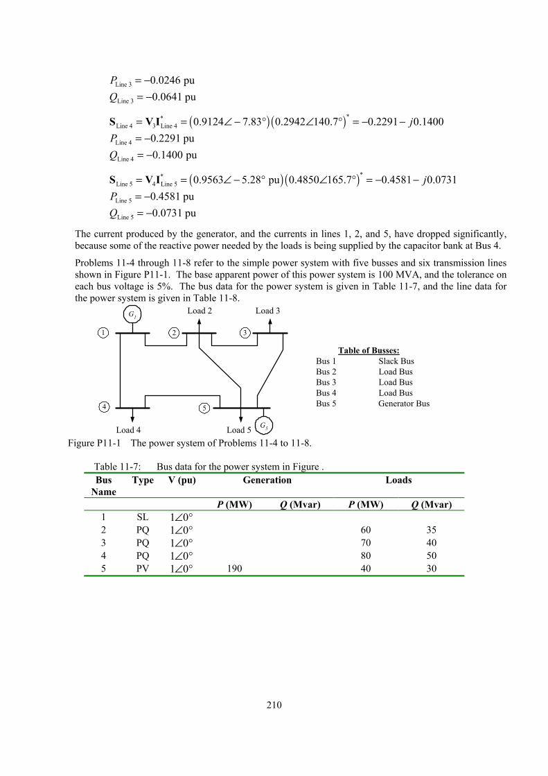
210
Line 3 0.0246 puP = − Line 3 0.0641 puQ = −
( ) ( )**Line 4 3 Line 4 0.9124 7.83 0.2942 140.7 0.2291 0.1400j= = ∠ − ° ∠ ° = − −S V I
Line 4 0.2291 puP = − Line 4 0.1400 puQ = −
( ) ( )**Line 5 4 Line 5 0.9563 5.28 pu 0.4850 165.7 0.4581 0.0731j= = ∠ − ° ∠ ° = − −S V I
Line 5 0.4581 puP = − Line 5 0.0731 puQ = −
The current produced by the generator, and the currents in lines 1, 2, and 5, have dropped significantly, because some of the reactive power needed by the loads is being supplied by the capacitor bank at Bus 4.
Problems 11-4 through 11-8 refer to the simple power system with five busses and six transmission lines shown in Figure P11-1. The base apparent power of this power system is 100 MVA, and the tolerance on each bus voltage is 5%. The bus data for the power system is given in Table 11-7, and the line data for the power system is given in Table 11-8.
G1
4
321
Load 2
Table of Busses:Bus 1 Slack BusBus 2 Load BusBus 3 Load BusBus 4 Load BusBus 5 Generator Bus5
Load 3
Load 4 Load 5 G5
Figure P11-1 The power system of Problems 11-4 to 11-8.
Table 11-7: Bus data for the power system in Figure . Bus
Name Type V (pu) Generation Loads
P (MW) Q (Mvar) P (MW) Q (Mvar) 1 SL 1 0∠ ° 2 PQ 1 0∠ ° 60 35 3 PQ 1 0∠ ° 70 40 4 PQ 1 0∠ ° 80 50 5 PV 1 0∠ ° 190 40 30
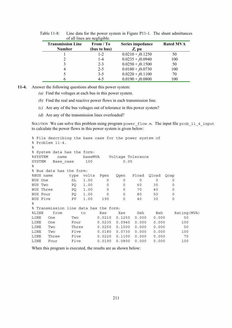
211
Table 11-8: Line data for the power system in Figure P11-1. The shunt admittances of all lines are negligible.
Transmission Line Number
From / To (bus to bus)
Series impedance Z, pu
Rated MVA
1 1-2 0.0210 + j0.1250 50 2 1-4 0.0235 + j0.0940 100 3 2-3 0.0250 + j0.1500 50 4 2-5 0.0180 + j0.0730 100 5 3-5 0.0220 + j0.1100 70 6 4-5 0.0190 + j0.0800 100
11-4. Answer the following questions about this power system: (a) Find the voltages at each bus in this power system.
(b) Find the real and reactive power flows in each transmission line.
(c) Are any of the bus voltages out of tolerance in this power system?
(d) Are any of the transmission lines overloaded?
SOLUTION We can solve this problem using program power_flow.m. The input file prob_11_4_input to calculate the power flows in this power system is given below:
% File describing the base case for the power system of% Problem 11-4.%% System data has the form:%SYSTEM name baseMVA Voltage ToleranceSYSTEM Base_case 100 0.05%% Bus data has the form:%BUS name type volts Pgen Qgen Pload Qload QcapBUS One SL 1.00 0 0 0 0 0BUS Two PQ 1.00 0 0 60 35 0BUS Three PQ 1.00 0 0 70 40 0BUS Four PQ 1.00 0 0 80 50 0BUS Five PV 1.00 190 0 40 30 0%% Transmission line data has the form:%LINE from to Rse Xse Gsh Bsh Rating(MVA)LINE One Two 0.0210 0.1250 0.000 0.000 50LINE One Four 0.0235 0.0940 0.000 0.000 100LINE Two Three 0.0250 0.1500 0.000 0.000 50LINE Two Five 0.0180 0.0730 0.000 0.000 100LINE Three Five 0.0220 0.1100 0.000 0.000 70LINE Four Five 0.0190 0.0800 0.000 0.000 100
When this program is executed, the results are as shown below:

212
>>power_flowprob_11_4_input
Inputsummarystatistics:
23linesinsystemfile
1SYSTEMlines
5BUSlines
6LINElines
ResultsforCaseBase_case
|====================BusInformation=======================================|=======LineInformation======|
Bus
Bus
Volts/angle
|--Generation--|------Load-----|--Cap--|
To
|----LineFlow---|
no.
Name
Type
(pu)
(deg)
(MW)
(MVAR)
(MW)
(MVAR)
(MVAR)
Bus
(MW)
(MVAR)|
|========================================================================================================|
1One
SL
1.000/
0.00
62.55
44.63
0.00
0.00
0.00
Two
26.52
19.76
Four
36.03
24.88
2Two
PQ
0.970/
-1.71
0.00
0.00
60.00
35.00
0.00
One
-26.29
-18.39
Three
15.97
10.10
Five
-49.52
-26.74
3Three
PQ
0.951/
-3.04
0.00
0.00
70.00
40.00
0.00
Two
-15.87
-9.54
Five
-54.07
-30.47
4Four
PQ
0.969/
-1.66
0.00
0.00
80.00
50.00
0.00
One
-35.58
-23.07
Five
-44.34
-26.95
5Five
PV
1.000/
0.14
190.00
123.56
40.00
30.00
0.00
Two
50.13
29.20
Three
55.01
35.16
Four
44.88
29.24
|========================================================================================================|
Totals
252.55
168.19
250.00
155.00
0.00
|========================================================================================================|
LineLosses
|=====================================================|
|Line
From
To
Ploss
Qloss
||
no.
Bus
Bus
(MW)
(MVAR)|
|=====================================================|
1One
Two
0.23
1.37
2One
Four
0.45
1.80
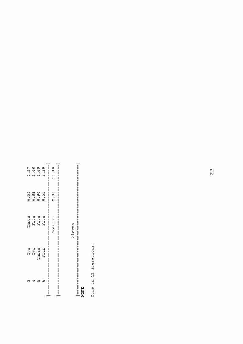
213
3Two
Three
0.09
0.57
4Two
Five
0.61
2.46
5Three
Five
0.94
4.69
6Four
Five
0.55
2.30
|=====================================================|
Totals:
2.86
13.18
|=====================================================|
Alerts
|=====================================================|
NONE
Donein12iterations.
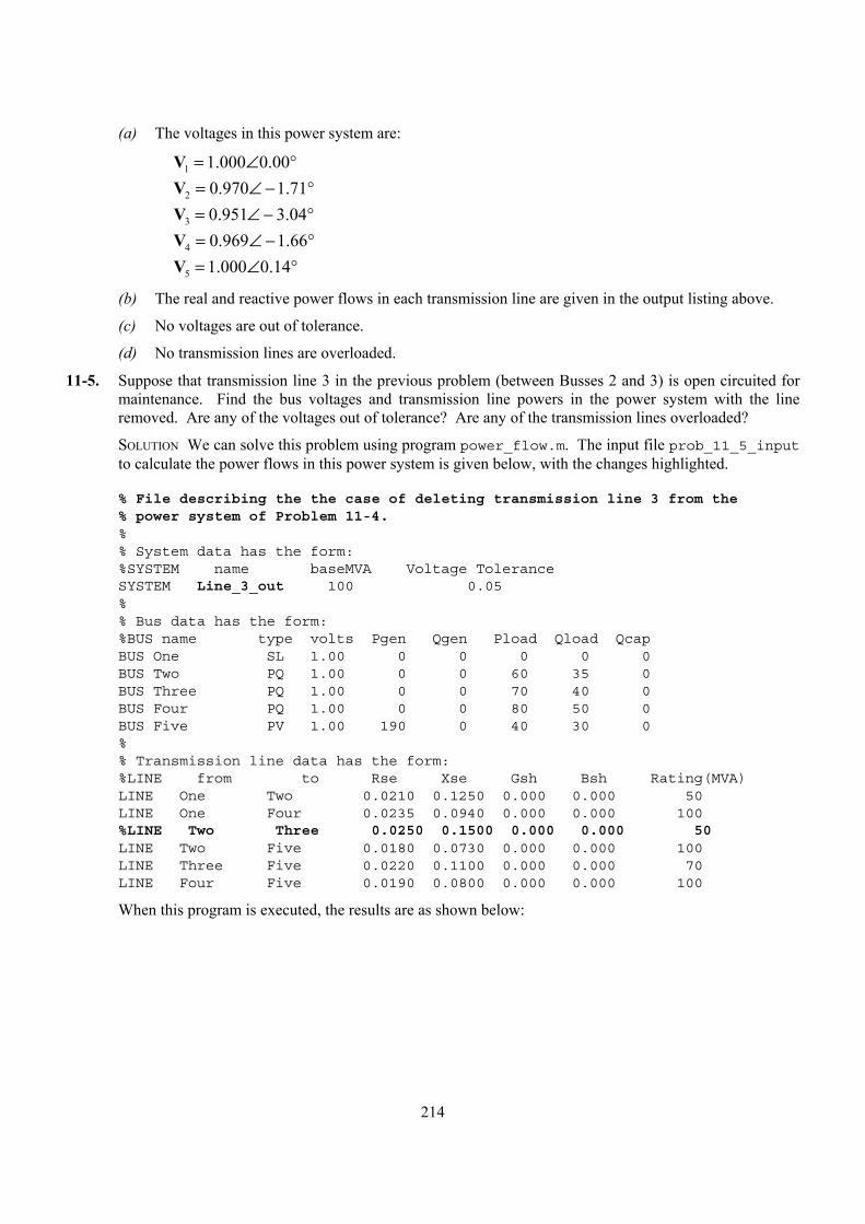
214
(a) The voltages in this power system are:
1
2
3
4
5
1.000 0.000.970 1.710.951 3.040.969 1.661.000 0.14
= ∠ °= ∠ − °= ∠ − °= ∠ − °= ∠ °
VVVVV
(b) The real and reactive power flows in each transmission line are given in the output listing above.
(c) No voltages are out of tolerance.
(d) No transmission lines are overloaded.
11-5. Suppose that transmission line 3 in the previous problem (between Busses 2 and 3) is open circuited for maintenance. Find the bus voltages and transmission line powers in the power system with the line removed. Are any of the voltages out of tolerance? Are any of the transmission lines overloaded?
SOLUTION We can solve this problem using program power_flow.m. The input file prob_11_5_input to calculate the power flows in this power system is given below, with the changes highlighted.
% File describing the the case of deleting transmission line 3 from the% power system of Problem 11-4.%% System data has the form:%SYSTEM name baseMVA Voltage ToleranceSYSTEM Line_3_out 100 0.05%% Bus data has the form:%BUS name type volts Pgen Qgen Pload Qload QcapBUS One SL 1.00 0 0 0 0 0BUS Two PQ 1.00 0 0 60 35 0BUS Three PQ 1.00 0 0 70 40 0BUS Four PQ 1.00 0 0 80 50 0BUS Five PV 1.00 190 0 40 30 0%% Transmission line data has the form:%LINE from to Rse Xse Gsh Bsh Rating(MVA)LINE One Two 0.0210 0.1250 0.000 0.000 50LINE One Four 0.0235 0.0940 0.000 0.000 100%LINE Two Three 0.0250 0.1500 0.000 0.000 50LINE Two Five 0.0180 0.0730 0.000 0.000 100LINE Three Five 0.0220 0.1100 0.000 0.000 70LINE Four Five 0.0190 0.0800 0.000 0.000 100
When this program is executed, the results are as shown below:
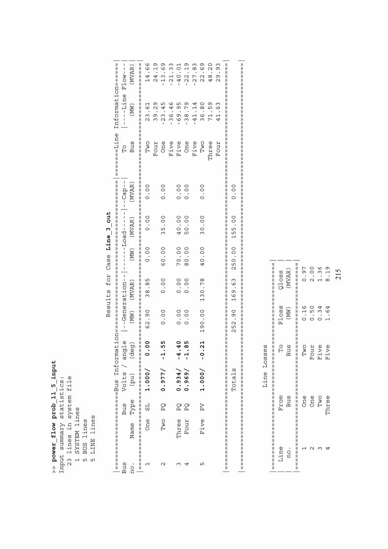
215
>>power_flowprob_11_5_input
Inputsummarystatistics:
23linesinsystemfile
1SYSTEMlines
5BUSlines
5LINElines
ResultsforCaseLine_3_out
|====================BusInformation=======================================|=======LineInformation======|
Bus
Bus
Volts/angle
|--Generation--|------Load-----|--Cap--|
To
|----LineFlow---|
no.
Name
Type
(pu)
(deg)
(MW)
(MVAR)
(MW)
(MVAR)
(MVAR)
Bus
(MW)
(MVAR)|
|========================================================================================================|
1One
SL
1.000/
0.00
62.90
38.85
0.00
0.00
0.00
Two
23.61
14.66
Four
39.29
24.19
2Two
PQ
0.977/
-1.55
0.00
0.00
60.00
35.00
0.00
One
-23.45
-13.69
Five
-36.46
-21.33
3Three
PQ
0.934/
-4.40
0.00
0.00
70.00
40.00
0.00
Five
-69.95
-40.01
4Four
PQ
0.969/
-1.85
0.00
0.00
80.00
50.00
0.00
One
-38.79
-22.19
Five
-41.14
-27.83
5Five
PV
1.000/
-0.21
190.00
130.78
40.00
30.00
0.00
Two
36.80
22.69
Three
71.59
48.20
Four
41.63
29.93
|========================================================================================================|
Totals
252.90
169.63
250.00
155.00
0.00
|========================================================================================================|
LineLosses
|=====================================================|
|Line
From
To
Ploss
Qloss
||
no.
Bus
Bus
(MW)
(MVAR)|
|=====================================================|
1One
Two
0.16
0.97
2One
Four
0.50
2.00
3Two
Five
0.34
1.36
4Three
Five
1.64
8.19
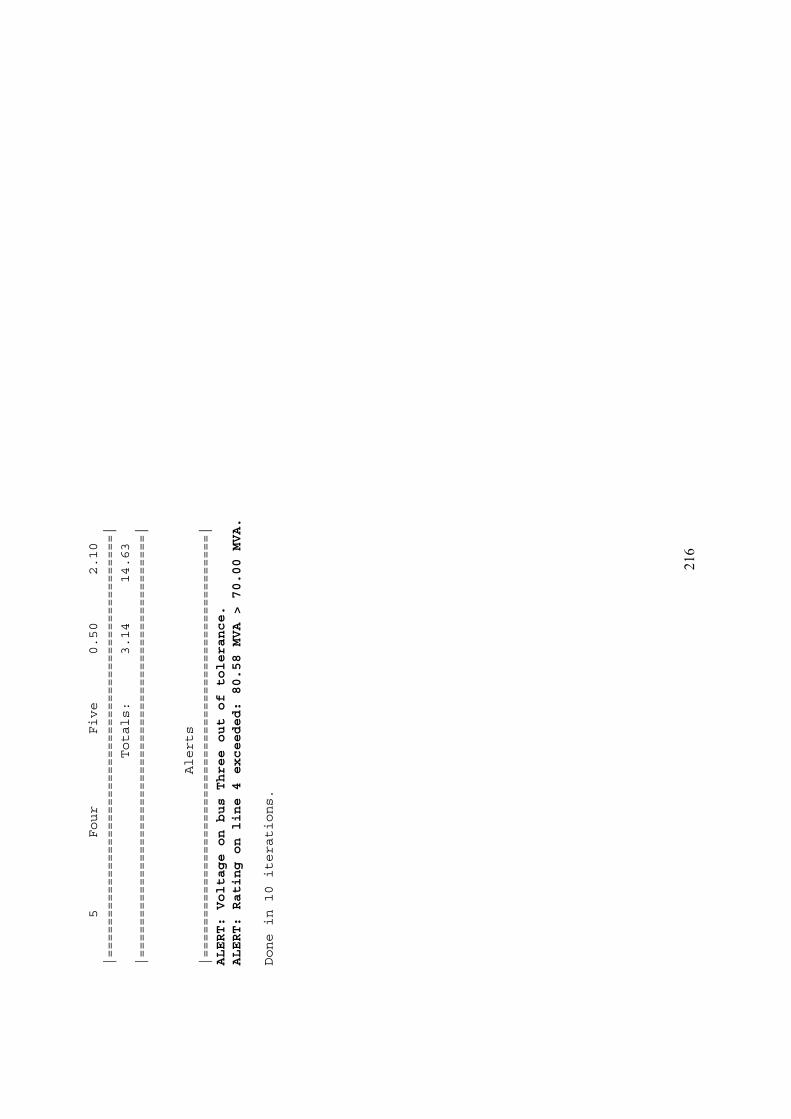
216
5Four
Five
0.50
2.10
|=====================================================|
Totals:
3.14
14.63
|=====================================================|
Alerts
|=====================================================|
ALERT:VoltageonbusThreeoutoftolerance.
ALERT:Ratingonline4exceeded:80.58MVA>70.00MVA.
Donein10iterations.
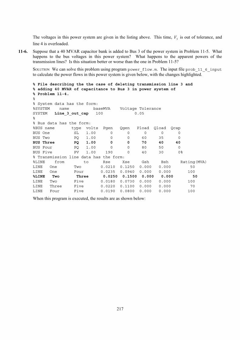
217
The voltages in this power system are given in the listing above. This time, 3V is out of tolerance, and line 4 is overloaded.
11-6. Suppose that a 40 MVAR capacitor bank is added to Bus 3 of the power system in Problem 11-5. What happens to the bus voltages in this power system? What happens to the apparent powers of the transmission lines? Is this situation better or worse than the one in Problem 11-5?
SOLUTION We can solve this problem using program power_flow.m. The input file prob_11_6_input to calculate the power flows in this power system is given below, with the changes highlighted.
% File describing the the case of deleting transmission line 3 and% adding 40 MVAR of capacitance to Bus 3 in power system of% Problem 11-4.%% System data has the form:%SYSTEM name baseMVA Voltage ToleranceSYSTEM Line_3_out_cap 100 0.05%% Bus data has the form:%BUS name type volts Pgen Qgen Pload Qload QcapBUS One SL 1.00 0 0 0 0 0BUS Two PQ 1.00 0 0 60 35 0BUS Three PQ 1.00 0 0 70 40 40BUS Four PQ 1.00 0 0 80 50 0BUS Five PV 1.00 190 0 40 30 0%% Transmission line data has the form:%LINE from to Rse Xse Gsh Bsh Rating(MVA)LINE One Two 0.0210 0.1250 0.000 0.000 50LINE One Four 0.0235 0.0940 0.000 0.000 100%LINE Two Three 0.0250 0.1500 0.000 0.000 50LINE Two Five 0.0180 0.0730 0.000 0.000 100LINE Three Five 0.0220 0.1100 0.000 0.000 70LINE Four Five 0.0190 0.0800 0.000 0.000 100
When this program is executed, the results are as shown below:
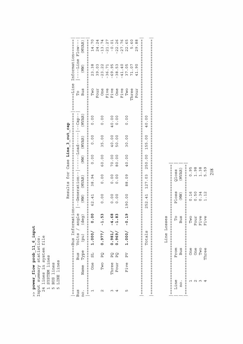
218
>>power_flowprob_11_6_input
Inputsummarystatistics:
24linesinsystemfile
1SYSTEMlines
5BUSlines
5LINElines
ResultsforCaseLine_3_out_cap
|====================BusInformation=======================================|=======LineInformation======|
Bus
Bus
Volts/angle
|--Generation--|------Load-----|--Cap--|
To
|----LineFlow---|
no.
Name
Type
(pu)
(deg)
(MW)
(MVAR)
(MW)
(MVAR)
(MVAR)
Bus
(MW)
(MVAR)|
|========================================================================================================|
1One
SL
1.000/
0.00
62.41
38.94
0.00
0.00
0.00
Two
23.38
14.70
Four
39.03
24.24
2Two
PQ
0.977/
-1.53
0.00
0.00
60.00
35.00
0.00
One
-23.22
-13.74
Five
-36.71
-21.27
3Three
PQ
0.981/
-4.68
0.00
0.00
70.00
40.00
40.00
Five
-69.95
-0.01
4Four
PQ
0.969/
-1.83
0.00
0.00
80.00
50.00
0.00
One
-38.53
-22.26
Five
-41.40
-27.76
5Five
PV
1.000/
-0.19
190.00
88.09
40.00
30.00
0.00
Two
37.05
22.65
Three
71.07
5.60
Four
41.90
29.88
|========================================================================================================|
Totals
252.41
127.03
250.00
155.00
40.00
|========================================================================================================|
LineLosses
|=====================================================|
|Line
From
To
Ploss
Qloss
||
no.
Bus
Bus
(MW)
(MVAR)|
|=====================================================|
1One
Two
0.16
0.95
2One
Four
0.50
1.98
3Two
Five
0.34
1.38
4Three
Five
1.12
5.59
219
5Four
Five
0.50
2.12
|=====================================================|
Totals:
2.62
12.02
|=====================================================|
Alerts
|=====================================================|
NONE
Donein10iterations.
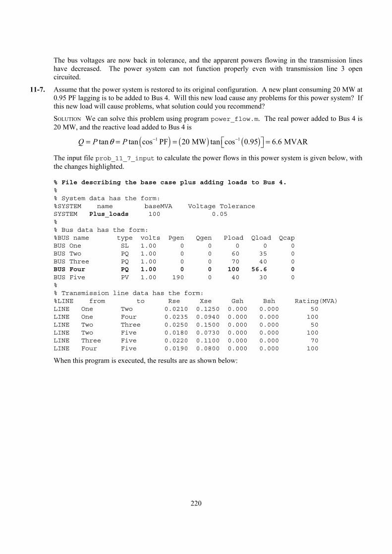
220
The bus voltages are now back in tolerance, and the apparent powers flowing in the transmission lines have decreased. The power system can not function properly even with transmission line 3 open circuited.
11-7. Assume that the power system is restored to its original configuration. A new plant consuming 20 MW at 0.95 PF lagging is to be added to Bus 4. Will this new load cause any problems for this power system? If this new load will cause problems, what solution could you recommend?
SOLUTION We can solve this problem using program power_flow.m. The real power added to Bus 4 is 20 MW, and the reactive load added to Bus 4 is
( ) ( ) ( )1 1tan tan cos PF 20 MW tan cos 0.95 6.6 MVARQ P Pθ − − = = = =
The input file prob_11_7_input to calculate the power flows in this power system is given below, with the changes highlighted.
% File describing the base case plus adding loads to Bus 4.%% System data has the form:%SYSTEM name baseMVA Voltage ToleranceSYSTEM Plus_loads 100 0.05%% Bus data has the form:%BUS name type volts Pgen Qgen Pload Qload QcapBUS One SL 1.00 0 0 0 0 0BUS Two PQ 1.00 0 0 60 35 0BUS Three PQ 1.00 0 0 70 40 0BUS Four PQ 1.00 0 0 100 56.6 0BUS Five PV 1.00 190 0 40 30 0%% Transmission line data has the form:%LINE from to Rse Xse Gsh Bsh Rating(MVA)LINE One Two 0.0210 0.1250 0.000 0.000 50LINE One Four 0.0235 0.0940 0.000 0.000 100LINE Two Three 0.0250 0.1500 0.000 0.000 50LINE Two Five 0.0180 0.0730 0.000 0.000 100LINE Three Five 0.0220 0.1100 0.000 0.000 70LINE Four Five 0.0190 0.0800 0.000 0.000 100
When this program is executed, the results are as shown below:
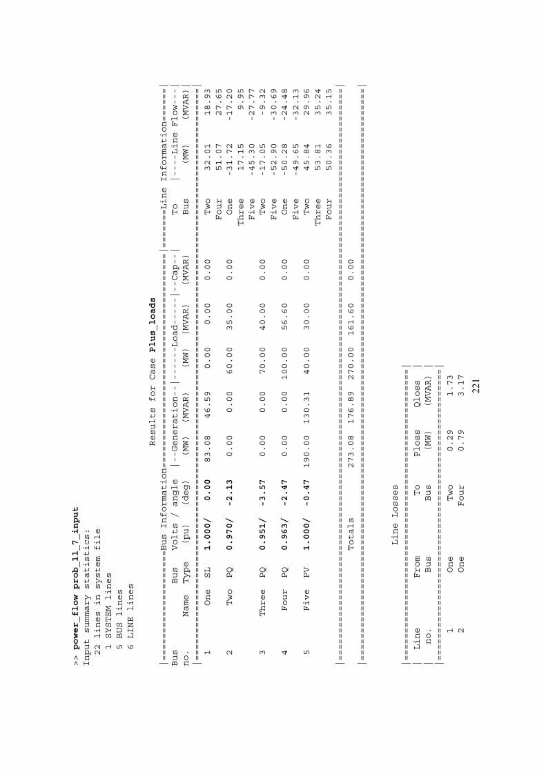
221
>>power_flowprob_11_7_input
Inputsummarystatistics:
22linesinsystemfile
1SYSTEMlines
5BUSlines
6LINElines
ResultsforCasePlus_loads
|====================BusInformation=======================================|=======LineInformation======|
Bus
Bus
Volts/angle
|--Generation--|------Load-----|--Cap--|
To
|----LineFlow---|
no.
Name
Type
(pu)
(deg)
(MW)
(MVAR)
(MW)
(MVAR)
(MVAR)
Bus
(MW)
(MVAR)|
|========================================================================================================|
1One
SL
1.000/
0.00
83.08
46.59
0.00
0.00
0.00
Two
32.01
18.93
Four
51.07
27.65
2Two
PQ
0.970/
-2.13
0.00
0.00
60.00
35.00
0.00
One
-31.72
-17.20
Three
17.15
9.95
Five
-45.30
-27.77
3Three
PQ
0.951/
-3.57
0.00
0.00
70.00
40.00
0.00
Two
-17.05
-9.32
Five
-52.90
-30.69
4Four
PQ
0.963/
-2.47
0.00
0.00
100.00
56.60
0.00
One
-50.28
-24.48
Five
-49.65
-32.13
5Five
PV
1.000/
-0.47
190.00
130.31
40.00
30.00
0.00
Two
45.84
29.96
Three
53.81
35.24
Four
50.36
35.15
|========================================================================================================|
Totals
273.08
176.89
270.00
161.60
0.00
|========================================================================================================|
LineLosses
|=====================================================|
|Line
From
To
Ploss
Qloss
||
no.
Bus
Bus
(MW)
(MVAR)|
|=====================================================|
1One
Two
0.29
1.73
2One
Four
0.79
3.17
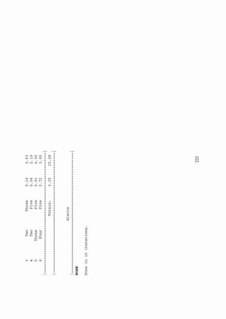
222
3Two
Three
0.10
0.63
4Two
Five
0.54
2.19
5Three
Five
0.91
4.55
6Four
Five
0.72
3.02
|=====================================================|
Totals:
3.35
15.28
|=====================================================|
Alerts
|=====================================================|
NONE
Donein15iterations.
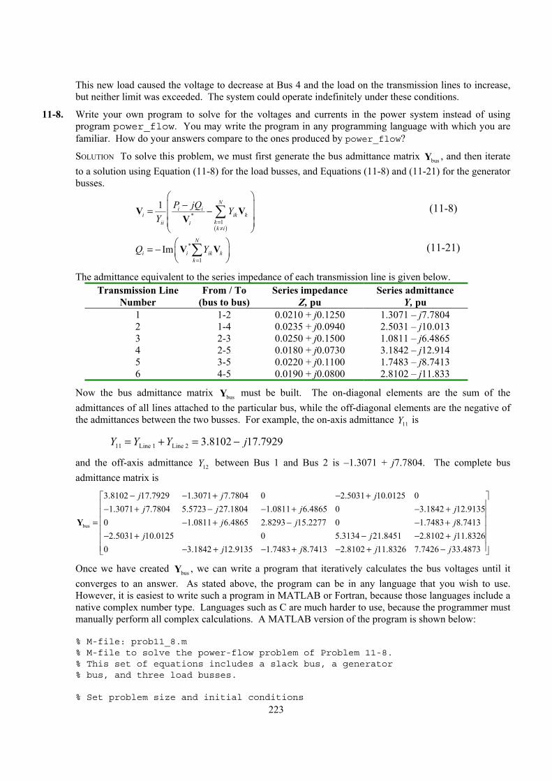
223
This new load caused the voltage to decrease at Bus 4 and the load on the transmission lines to increase, but neither limit was exceeded. The system could operate indefinitely under these conditions.
11-8. Write your own program to solve for the voltages and currents in the power system instead of using program power_flow. You may write the program in any programming language with which you are familiar. How do your answers compare to the ones produced by power_flow?
SOLUTION To solve this problem, we must first generate the bus admittance matrix busY , and then iterate to a solution using Equation (11-8) for the load busses, and Equations (11-8) and (11-21) for the generator busses.
( )
*1
1 Ni i
i ik kkii ik i
P jQ YY =
≠
− = −
∑V VV
(11-8)
*
1
ImN
i i ik kk
Q Y=
= −
∑V V (11-21)
The admittance equivalent to the series impedance of each transmission line is given below. Transmission Line
Number From / To
(bus to bus) Series impedance
Z, pu Series admittance
Y, pu 1 1-2 0.0210 + j0.1250 1.3071 – j7.7804 2 1-4 0.0235 + j0.0940 2.5031 – j10.013 3 2-3 0.0250 + j0.1500 1.0811 – j6.4865 4 2-5 0.0180 + j0.0730 3.1842 – j12.914 5 3-5 0.0220 + j0.1100 1.7483 – j8.7413 6 4-5 0.0190 + j0.0800 2.8102 – j11.833
Now the bus admittance matrix busY must be built. The on-diagonal elements are the sum of the admittances of all lines attached to the particular bus, while the off-diagonal elements are the negative of the admittances between the two busses. For example, the on-axis admittance 11Y is
11 Line 1 Line 2 3.8102 17.7929Y Y Y j= + = −
and the off-axis admittance 12Y between Bus 1 and Bus 2 is –1.3071 + j7.7804. The complete bus admittance matrix is
bus
3.8102 17.7929 1.3071 7.7804 0 2.5031 10.0125 01.3071 7.7804 5.5723 27.1804 1.0811 6.4865 0 3.1842 12.9135
0 1.0811 6.4865 2.8293 15.2277 0 1.7483 8.74132.5031 10.0125 0 5.3134 21.8451 2.810
j j jj j j j
j j jj j
− − + − +− + − − + − +
= − + − − +− + − −
Y2 11.8326
0 3.1842 12.9135 1.7483 8.7413 2.8102 11.8326 7.7426 33.4873j
j j j j
+ − + − + − + −
Once we have created busY , we can write a program that iteratively calculates the bus voltages until it converges to an answer. As stated above, the program can be in any language that you wish to use. However, it is easiest to write such a program in MATLAB or Fortran, because those languages include a native complex number type. Languages such as C are much harder to use, because the programmer must manually perform all complex calculations. A MATLAB version of the program is shown below:
% M-file: prob11_8.m% M-file to solve the power-flow problem of Problem 11-8.% This set of equations includes a slack bus, a generator% bus, and three load busses.
% Set problem size and initial conditions
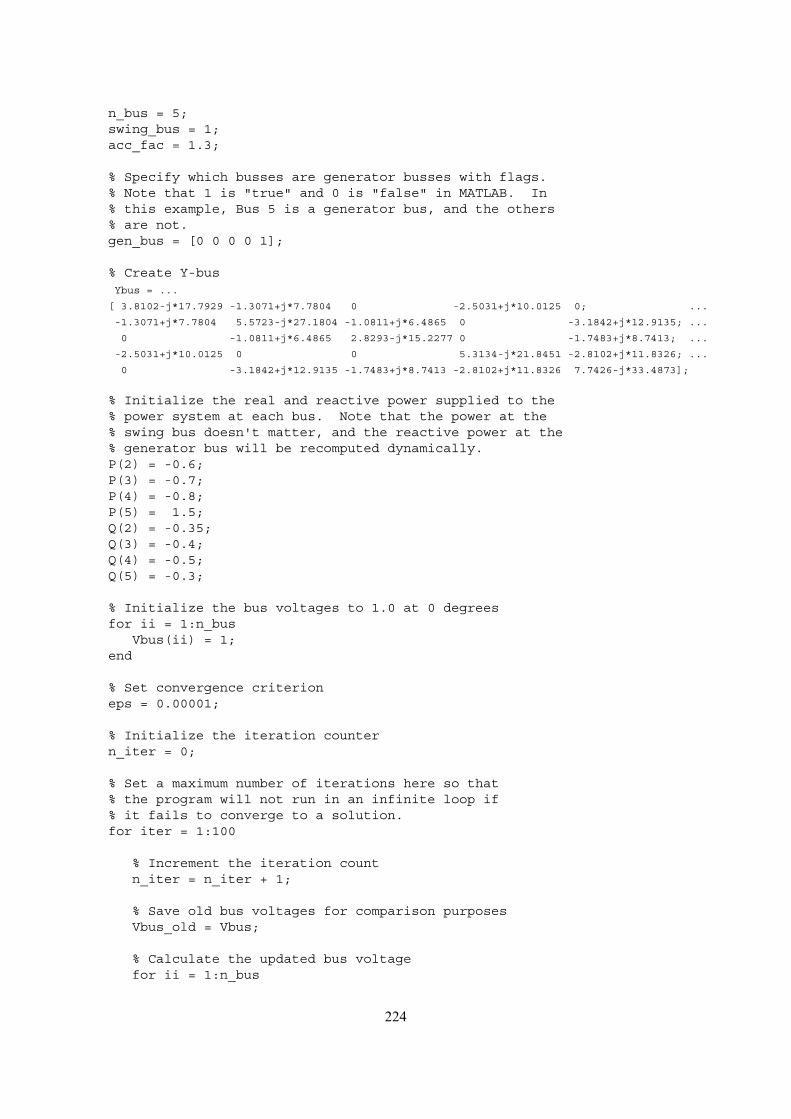
224
n_bus = 5;swing_bus = 1;acc_fac = 1.3;
% Specify which busses are generator busses with flags.% Note that 1 is "true" and 0 is "false" in MATLAB. In% this example, Bus 5 is a generator bus, and the others% are not.gen_bus = [0 0 0 0 1];
% Create Y-busYbus = ...
[ 3.8102-j*17.7929 -1.3071+j*7.7804 0 -2.5031+j*10.0125 0; ...
-1.3071+j*7.7804 5.5723-j*27.1804 -1.0811+j*6.4865 0 -3.1842+j*12.9135; ...
0 -1.0811+j*6.4865 2.8293-j*15.2277 0 -1.7483+j*8.7413; ...
-2.5031+j*10.0125 0 0 5.3134-j*21.8451 -2.8102+j*11.8326; ...
0 -3.1842+j*12.9135 -1.7483+j*8.7413 -2.8102+j*11.8326 7.7426-j*33.4873];
% Initialize the real and reactive power supplied to the% power system at each bus. Note that the power at the% swing bus doesn't matter, and the reactive power at the% generator bus will be recomputed dynamically.P(2) = -0.6;P(3) = -0.7;P(4) = -0.8;P(5) = 1.5;Q(2) = -0.35;Q(3) = -0.4;Q(4) = -0.5;Q(5) = -0.3;
% Initialize the bus voltages to 1.0 at 0 degreesfor ii = 1:n_bus
Vbus(ii) = 1;end
% Set convergence criterioneps = 0.00001;
% Initialize the iteration countern_iter = 0;
% Set a maximum number of iterations here so that% the program will not run in an infinite loop if% it fails to converge to a solution.for iter = 1:100
% Increment the iteration countn_iter = n_iter + 1;
% Save old bus voltages for comparison purposesVbus_old = Vbus;
% Calculate the updated bus voltagefor ii = 1:n_bus

225
% Skip the swing bus!if ii ~= swing_bus
% If this is a generator bus, update the reactive% power estimate.if gen_bus(ii)
temp = 0;for jj = 1:n_bus
temp = temp + Ybus(ii,jj) * Vbus(jj);endtemp = conj(Vbus(ii)) * temp;Q(ii) = -imag(temp);
end
% Calculate updated voltage at bus 'ii'. First, sum% up the current contributions at bus 'ii' from all% other busses.temp = 0;for jj = 1:n_bus
if ii ~= jjtemp = temp - Ybus(ii,jj) * Vbus(jj);
endend
% Add in the current injected at this nodetemp = (P(ii) - j*Q(ii)) / conj(Vbus(ii)) + temp;
% Get updated estimate of Vbus at 'ii'Vnew = 1/Ybus(ii,ii) * temp;
% Apply an acceleration factor to the new voltage estimateVbus(ii) = Vbus_old(ii) + acc_fac * (Vnew - Vbus_old(ii));
% If this is a generator bus, update the magnitude of the% voltage to keep it constant.if gen_bus(ii)
Vbus(ii) = Vbus(ii) * abs(Vbus_old(ii)) / abs(Vbus(ii));end
endend
% Compare the old and new estimate of the voltages.% Note that we will compare the real and the imag parts% separately, and both must be within tolerances.test = 0;for ii = 1:n_bus
% Compare real partsif abs( real(Vbus(ii)) - real(Vbus_old(ii)) ) > eps
test = 1;end
% Compare imaginary partsif abs( imag(Vbus(ii)) - imag(Vbus_old(ii)) ) > eps
test = 1;end

226
end
% Did we converge? If so, get out of the loop.if test == 0
break;end
end
% Did we exceed the maximum number of iterations?if iter == 100
disp('Max number of iterations exceeded!');end
% Display resultsfor ii = 1:n_bus
[mag, phase] = r2p(Vbus(ii));str = ['The voltage at bus ' int2str(ii) ' = ' ...
num2str(mag) '/' num2str(phase)];disp(str);
end
% Calculate the current flowing and power transmitted% between each pair of bussesSline = zeros(n_bus,n_bus);Pline = zeros(n_bus,n_bus);Qline = zeros(n_bus,n_bus);for ii = 1:n_bus
for jj = 1:n_bus
% Skip own busif ii == jj
continue;end
% Calculate line currentIline(ii,jj) = Ybus(ii,jj) * ( Vbus(ii) - Vbus(jj) );
% Calculate complex power flowSline(ii,jj) = Vbus(ii) * conj( Iline(ii,jj) );
% Calculate real and reactive componentsPline(ii,jj) = real(Sline(ii,jj));Qline(ii,jj) = imag(Sline(ii,jj));
endend
% Display currentsfor ii = 1:n_bus
for jj = 1:n_bus
% Skip own busif ii == jj
continue;end
[mag, phase] = r2p(Iline(ii,jj));
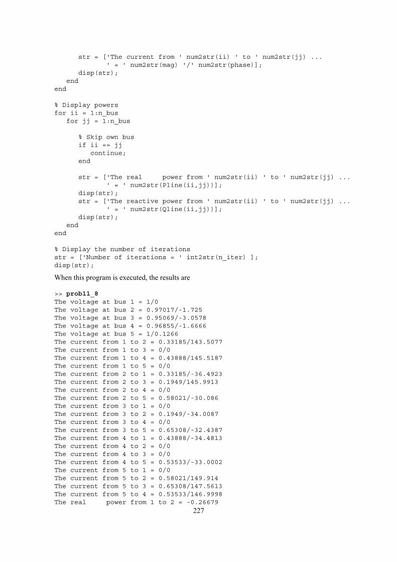
227
str = ['The current from ' num2str(ii) ' to ' num2str(jj) ...' = ' num2str(mag) '/' num2str(phase)];
disp(str);end
end
% Display powersfor ii = 1:n_bus
for jj = 1:n_bus
% Skip own busif ii == jj
continue;end
str = ['The real power from ' num2str(ii) ' to ' num2str(jj) ...' = ' num2str(Pline(ii,jj))];
disp(str);str = ['The reactive power from ' num2str(ii) ' to ' num2str(jj) ...
' = ' num2str(Qline(ii,jj))];disp(str);
endend
% Display the number of iterationsstr = ['Number of iterations = ' int2str(n_iter) ];disp(str);
When this program is executed, the results are
>> prob11_8The voltage at bus 1 = 1/0The voltage at bus 2 = 0.97017/-1.725The voltage at bus 3 = 0.95069/-3.0578The voltage at bus 4 = 0.96855/-1.6666The voltage at bus 5 = 1/0.1266The current from 1 to 2 = 0.33185/143.5077The current from 1 to 3 = 0/0The current from 1 to 4 = 0.43888/145.5187The current from 1 to 5 = 0/0The current from 2 to 1 = 0.33185/-36.4923The current from 2 to 3 = 0.1949/145.9913The current from 2 to 4 = 0/0The current from 2 to 5 = 0.58021/-30.086The current from 3 to 1 = 0/0The current from 3 to 2 = 0.1949/-34.0087The current from 3 to 4 = 0/0The current from 3 to 5 = 0.65308/-32.4387The current from 4 to 1 = 0.43888/-34.4813The current from 4 to 2 = 0/0The current from 4 to 3 = 0/0The current from 4 to 5 = 0.53533/-33.0002The current from 5 to 1 = 0/0The current from 5 to 2 = 0.58021/149.914The current from 5 to 3 = 0.65308/147.5613The current from 5 to 4 = 0.53533/146.9998The real power from 1 to 2 = -0.26679
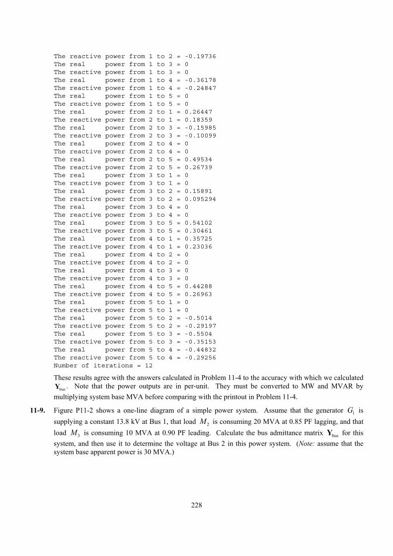
228
The reactive power from 1 to 2 = -0.19736The real power from 1 to 3 = 0The reactive power from 1 to 3 = 0The real power from 1 to 4 = -0.36178The reactive power from 1 to 4 = -0.24847The real power from 1 to 5 = 0The reactive power from 1 to 5 = 0The real power from 2 to 1 = 0.26447The reactive power from 2 to 1 = 0.18359The real power from 2 to 3 = -0.15985The reactive power from 2 to 3 = -0.10099The real power from 2 to 4 = 0The reactive power from 2 to 4 = 0The real power from 2 to 5 = 0.49534The reactive power from 2 to 5 = 0.26739The real power from 3 to 1 = 0The reactive power from 3 to 1 = 0The real power from 3 to 2 = 0.15891The reactive power from 3 to 2 = 0.095294The real power from 3 to 4 = 0The reactive power from 3 to 4 = 0The real power from 3 to 5 = 0.54102The reactive power from 3 to 5 = 0.30461The real power from 4 to 1 = 0.35725The reactive power from 4 to 1 = 0.23036The real power from 4 to 2 = 0The reactive power from 4 to 2 = 0The real power from 4 to 3 = 0The reactive power from 4 to 3 = 0The real power from 4 to 5 = 0.44288The reactive power from 4 to 5 = 0.26963The real power from 5 to 1 = 0The reactive power from 5 to 1 = 0The real power from 5 to 2 = -0.5014The reactive power from 5 to 2 = -0.29197The real power from 5 to 3 = -0.5504The reactive power from 5 to 3 = -0.35153The real power from 5 to 4 = -0.44832The reactive power from 5 to 4 = -0.29256Number of iterations = 12
These results agree with the answers calculated in Problem 11-4 to the accuracy with which we calculated busY . Note that the power outputs are in per-unit. They must be converted to MW and MVAR by
multiplying system base MVA before comparing with the printout in Problem 11-4.
11-9. Figure P11-2 shows a one-line diagram of a simple power system. Assume that the generator 1G is supplying a constant 13.8 kV at Bus 1, that load 2M is consuming 20 MVA at 0.85 PF lagging, and that load 3M is consuming 10 MVA at 0.90 PF leading. Calculate the bus admittance matrix busY for this system, and then use it to determine the voltage at Bus 2 in this power system. (Note: assume that the system base apparent power is 30 MVA.)
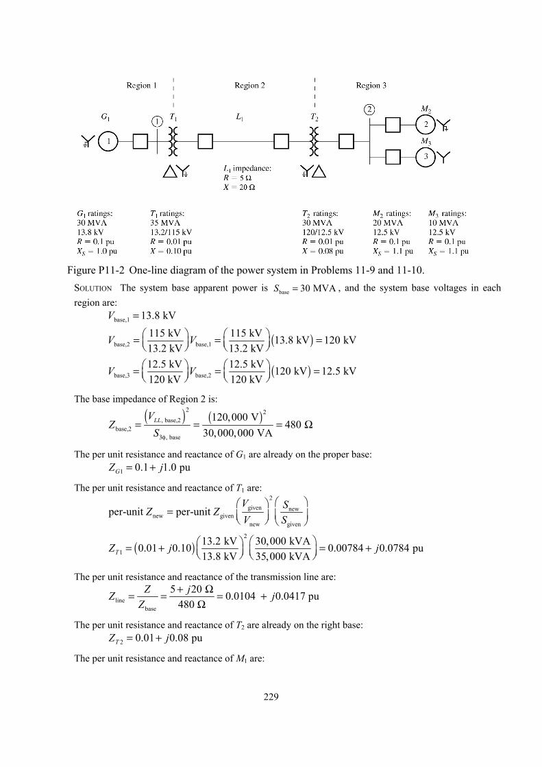
229
Figure P11-2 One-line diagram of the power system in Problems 11-9 and 11-10.
SOLUTION The system base apparent power is base 30 MVAS = , and the system base voltages in each region are:
base,1 13.8 kVV =
( )base,2 base,1115 kV 115 kV 13.8 kV 120 kV13.2 kV 13.2 kV
V V = = =
( )base,3 base,212.5 kV 12.5 kV 120 kV 12.5 kV120 kV 120 kV
V V = = =
The base impedance of Region 2 is:
( ) ( )
2 2, base,2
base,2, base
120,000 V480
30,000,000 VALLV
ZS3φ
= = = Ω
The per unit resistance and reactance of G1 are already on the proper base: 1 0.1 1.0 puGZ j= +
The per unit resistance and reactance of T1 are:
2
given newnew given
new given
per-unit per-unit V SZ ZV S
=
( )2
113.2 kV 30,000 kVA0.01 0.10 0.00784 0.0784 pu13.8 kV 35,000 kVATZ j j = + = +
The per unit resistance and reactance of the transmission line are:
linebase
5 20 0.0104 0.0417 pu480
Z jZ jZ
+ Ω= = = +Ω
The per unit resistance and reactance of T2 are already on the right base: 2 0.01 0.08 puTZ j= +
The per unit resistance and reactance of M1 are:
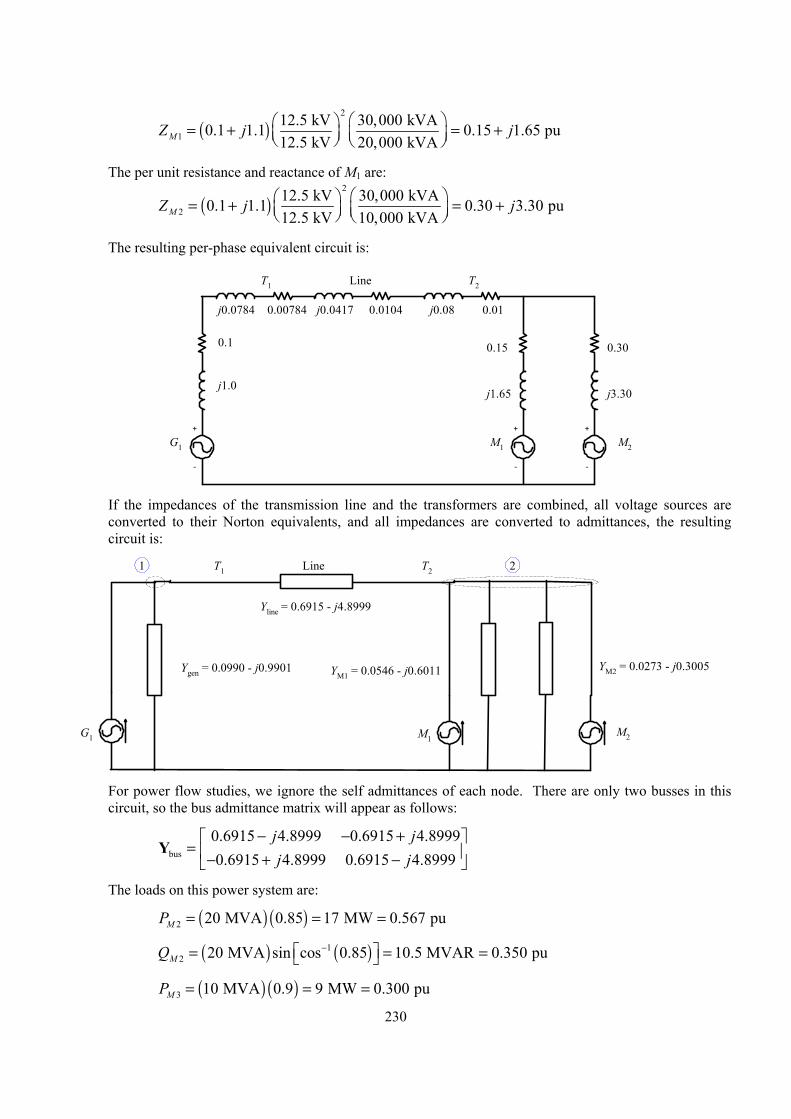
230
( )2
112.5 kV 30,000 kVA0.1 1.1 0.15 1.65 pu12.5 kV 20,000 kVAMZ j j = + = +
The per unit resistance and reactance of M1 are:
( )2
212.5 kV 30,000 kVA0.1 1.1 0.30 3.30 pu12.5 kV 10,000 kVAMZ j j = + = +
The resulting per-phase equivalent circuit is:
+
-
G1 M2
LineT1 T2
+
-
+
-
M1
0.1
j1.0
j0.0784 j0.0417 j0.08
j1.65
0.15
0.00784 0.0104 0.01
j3.30
0.30
If the impedances of the transmission line and the transformers are combined, all voltage sources are
converted to their Norton equivalents, and all impedances are converted to admittances, the resulting circuit is:
G1 M2
LineT1 T2
M1
21
Ygen = 0.0990 - j0.9901
Yline = 0.6915 - j4.8999
YM1 = 0.0546 - j0.6011 YM2 = 0.0273 - j0.3005
For power flow studies, we ignore the self admittances of each node. There are only two busses in this
circuit, so the bus admittance matrix will appear as follows:
bus
0.6915 4.8999 0.6915 4.89990.6915 4.8999 0.6915 4.8999
j jj j
− − + = − + −
Y
The loads on this power system are:
( ) ( )2 20 MVA 0.85 17 MW 0.567 puMP = = =
( ) ( )12 20 MVA sin cos 0.85 10.5 MVAR 0.350 puMQ − = = =
( ) ( )3 10 MVA 0.9 9 MW 0.300 puMP = = =
231
( ) ( )13 10 MVA sin cos 0.9 4.36 MVAR 0.145 puMQ − = − = − = −
The voltages on the busses can be calculated by iteration. A simple program to do so follows:
% M-file: prob11_9.m% M-file to solve the power-flow problem of Problem 11-9.% This set of equations includes a slack bus and a single% load bus.
% Set problem size and initial conditionsn_bus = 2;swing_bus = 1;acc_fac = 1.3;
% Create Y-busYbus = ...[ 0.6915-j*4.8999 -0.6915+j*4.8999; ...-0.6915+j*4.8999 0.6915-j*4.8999];
% Initialize the real and reactive power supplied to the% power system at each bus. Note that the power at the% swing bus doesn't matter, and the reactive power at the% generator bus will be recomputed dynamically.P(2) = -0.867;Q(2) = -0.205;
% Initialize the bus voltages to 1.0 at 0 degreesfor ii = 1:n_bus
Vbus(ii) = 1;end
% Set convergence criterioneps = 0.00001;
% Initialize the iteration countern_iter = 0;
% Set a maximum number of iterations here so that% the program will not run in an infinite loop if% it fails to converge to a solution.for iter = 1:100
% Increment the iteration countn_iter = n_iter + 1;
% Save old bus voltages for comparison purposesVbus_old = Vbus;
% Calculate the updated bus voltagefor ii = 1:n_bus
% Skip the swing bus!if ii ~= swing_bus
% Calculate updated voltage at bus 'ii'. First, sum% up the current contributions at bus 'ii' from all

232
% other busses.temp = 0;for jj = 1:n_bus
if ii ~= jjtemp = temp - Ybus(ii,jj) * Vbus(jj);
endend
% Add in the current injected at this nodetemp = (P(ii) - j*Q(ii)) / conj(Vbus(ii)) + temp;
% Get updated estimate of Vbus at 'ii'Vnew = 1/Ybus(ii,ii) * temp;
% Apply an acceleration factor to the new voltage estimateVbus(ii) = Vbus_old(ii) + acc_fac * (Vnew - Vbus_old(ii));
endend
% Compare the old and new estimate of the voltages.% Note that we will compare the real and the imag parts% separately, and both must be within tolerances.test = 0;for ii = 1:n_bus
% Compare real partsif abs( real(Vbus(ii)) - real(Vbus_old(ii)) ) > eps
test = 1;end
% Compare imaginary partsif abs( imag(Vbus(ii)) - imag(Vbus_old(ii)) ) > eps
test = 1;end
end
% Did we converge? If so, get out of the loop.if test == 0
break;end
end
% Did we exceed the maximum number of iterations?if iter == 100
disp('Max number of iterations exceeded!');end
% Display resultsfor ii = 1:n_bus
[mag, phase] = r2p(Vbus(ii));str = ['The voltage at bus ' int2str(ii) ' = ' ...
num2str(mag) '/' num2str(phase)];disp(str);
end
When this program is executed, the results are:
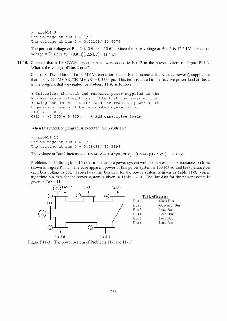
233
>> prob11_9The voltage at bus 1 = 1/0The voltage at bus 2 = 0.91101/-10.6076
The per-unit voltage at Bus 2 is 0.911 10.6∠ − ° . Since the base voltage at Bus 2 is 12.5 kV, the actual voltage at Bus 2 is ( ) ( )2 0.911 12.5 kV 11.4 kVV = =
11-10. Suppose that a 10 MVAR capacitor bank were added to Bus 2 in the power system of Figure P11-2. What is the voltage of Bus 2 now?
SOLUTION The addition of a 10 MVAR capacitor bank at Bus 2 increases the reactive power Q supplied to that bus by (10 MVAR)/(30 MVAR) = 0.3333 pu. This term is added to the reactive power load at Bus 2 in the program that we created for Problem 11-9, as follows:
% Initialize the real and reactive power supplied to the% power system at each bus. Note that the power at the% swing bus doesn't matter, and the reactive power at the% generator bus will be recomputed dynamically.P(2) = -0.867;Q(2) = -0.205 + 0.333; % Add capacitive loads...
When this modified program is executed, the results are:
>> prob11_10The voltage at bus 1 = 1/0The voltage at bus 2 = 0.98485/-10.3598
The voltage at Bus 2 increases to 0.9849 10.4 pu∠ − ° , or ( ) ( )2 0.9849 12.5 kV 12.3 kVV = = .
Problems 11-11 through 11-15 refer to the simple power system with six busses and six transmission lines shown in Figure P11-3. The base apparent power of this power system is 100 MVA, and the tolerance on each bus voltage is 5%. Typical daytime bus data for the power system is given in Table 11-9, typical nighttime bus data for the power system is given in Table 11-10. The line data for the power system is given in Table 11-11.
G1
432
1
Load 2
Table of Busses:Bus 1 Slack BusBus 2 Generator BusBus 3 Load BusBus 4 Load BusBus 5 Load BusBus 6 Load Bus
5
Load 3 Load 4
Load 5
6
Load 6
G2
Figure P11-3 The power system of Problems 11-11 to 11-15.
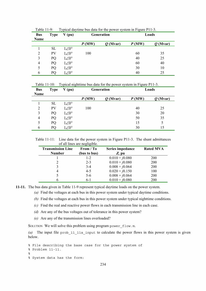
234
Table 11-9: Typical daytime bus data for the power system in Figure P11-3. Bus
Name Type V (pu) Generation Loads
P (MW) Q (Mvar) P (MW) Q (Mvar) 1 SL 1 0∠ ° 2 PV 1 0∠ ° 100 60 35 3 PQ 1 0∠ ° 40 25 4 PQ 1 0∠ ° 60 40 5 PQ 1 0∠ ° 30 10 6 PQ 1 0∠ ° 40 25
Table 11-10: Typical nighttime bus data for the power system in Figure P11-3. Bus
Name Type V (pu) Generation Loads
P (MW) Q (Mvar) P (MW) Q (Mvar) 1 SL 1 0∠ ° 2 PV 1 0∠ ° 100 40 25 3 PQ 1 0∠ ° 30 20 4 PQ 1 0∠ ° 50 35 5 PQ 1 0∠ ° 15 5 6 PQ 1 0∠ ° 30 15
Table 11-11: Line data for the power system in Figure P11-3. The shunt admittances
of all lines are negligible. Transmission Line
Number From / To
(bus to bus) Series impedance
Z, pu Rated MVA
1 1-2 0.010 + j0.080 200 2 2-3 0.010 + j0.080 200 3 3-4 0.008 + j0.064 200 4 4-5 0.020 + j0.150 100 5 5-6 0.008 + j0.064 200 6 6-1 0.010 + j0.080 200
11-11. The bus data given in Table 11-9 represent typical daytime loads on the power system. (a) Find the voltages at each bus in this power system under typical daytime conditions.
(b) Find the voltages at each bus in this power system under typical nighttime conditions.
(c) Find the real and reactive power flows in each transmission line in each case.
(d) Are any of the bus voltages out of tolerance in this power system?
(e) Are any of the transmission lines overloaded?
SOLUTION We will solve this problem using program power_flow.m.
(a) The input file prob_11_11a_input to calculate the power flows in this power system is given below.
% File describing the base case for the power system of% Problem 11-11.%% System data has the form:
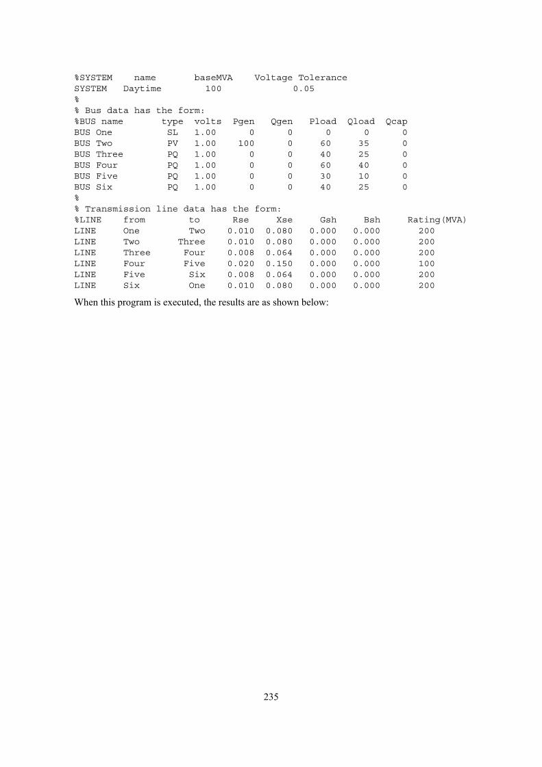
235
%SYSTEM name baseMVA Voltage ToleranceSYSTEM Daytime 100 0.05%% Bus data has the form:%BUS name type volts Pgen Qgen Pload Qload QcapBUS One SL 1.00 0 0 0 0 0BUS Two PV 1.00 100 0 60 35 0BUS Three PQ 1.00 0 0 40 25 0BUS Four PQ 1.00 0 0 60 40 0BUS Five PQ 1.00 0 0 30 10 0BUS Six PQ 1.00 0 0 40 25 0%% Transmission line data has the form:%LINE from to Rse Xse Gsh Bsh Rating(MVA)LINE One Two 0.010 0.080 0.000 0.000 200LINE Two Three 0.010 0.080 0.000 0.000 200LINE Three Four 0.008 0.064 0.000 0.000 200LINE Four Five 0.020 0.150 0.000 0.000 100LINE Five Six 0.008 0.064 0.000 0.000 200LINE Six One 0.010 0.080 0.000 0.000 200
When this program is executed, the results are as shown below:

236
>>power_flowprob_11_11a_input
Inputsummarystatistics:
24linesinsystemfile
1SYSTEMlines
6BUSlines
6LINElines
ResultsforCaseDaytime
|====================BusInformation=======================================|=======LineInformation======|
Bus
Bus
Volts/angle
|--Generation--|------Load-----|--Cap--|
To
|----LineFlow---|
no.
Name
Type
(pu)
(deg)
(MW)
(MVAR)
(MW)
(MVAR)
(MVAR)
Bus
(MW)
(MVAR)|
|========================================================================================================|
1One
SL
1.000/
0.00
132.71
50.20
0.00
0.00
0.00
Two
44.21
-4.72
Six
88.50
54.92
2Two
PV
1.000/
-2.05
100.00
109.02
60.00
35.00
0.00
One
-44.01
6.30
Three
84.14
67.76
3Three
PQ
0.939/
-5.75
0.00
0.00
40.00
25.00
0.00
Two
-82.98
-58.42
Four
43.11
33.46
4Four
PQ
0.913/
-7.41
0.00
0.00
60.00
40.00
0.00
Three
-42.84
-31.30
Five
-17.13
-8.68
5Five
PQ
0.932/
-5.80
0.00
0.00
30.00
10.00
0.00
Four
17.22
9.35
Six
-47.17
-19.33
6Six
PQ
0.949/
-3.94
0.00
0.00
40.00
25.00
0.00
Five
47.41
21.25
One
-87.41
-46.24
|========================================================================================================|
Totals
232.71
159.22
230.00
135.00
0.00
|========================================================================================================|
LineLosses
|=====================================================|
|Line
From
To
Ploss
Qloss
||
no.
Bus
Bus
(MW)
(MVAR)|
|=====================================================|
1One
Two
0.20
1.58
2Two
Three
1.17
9.34
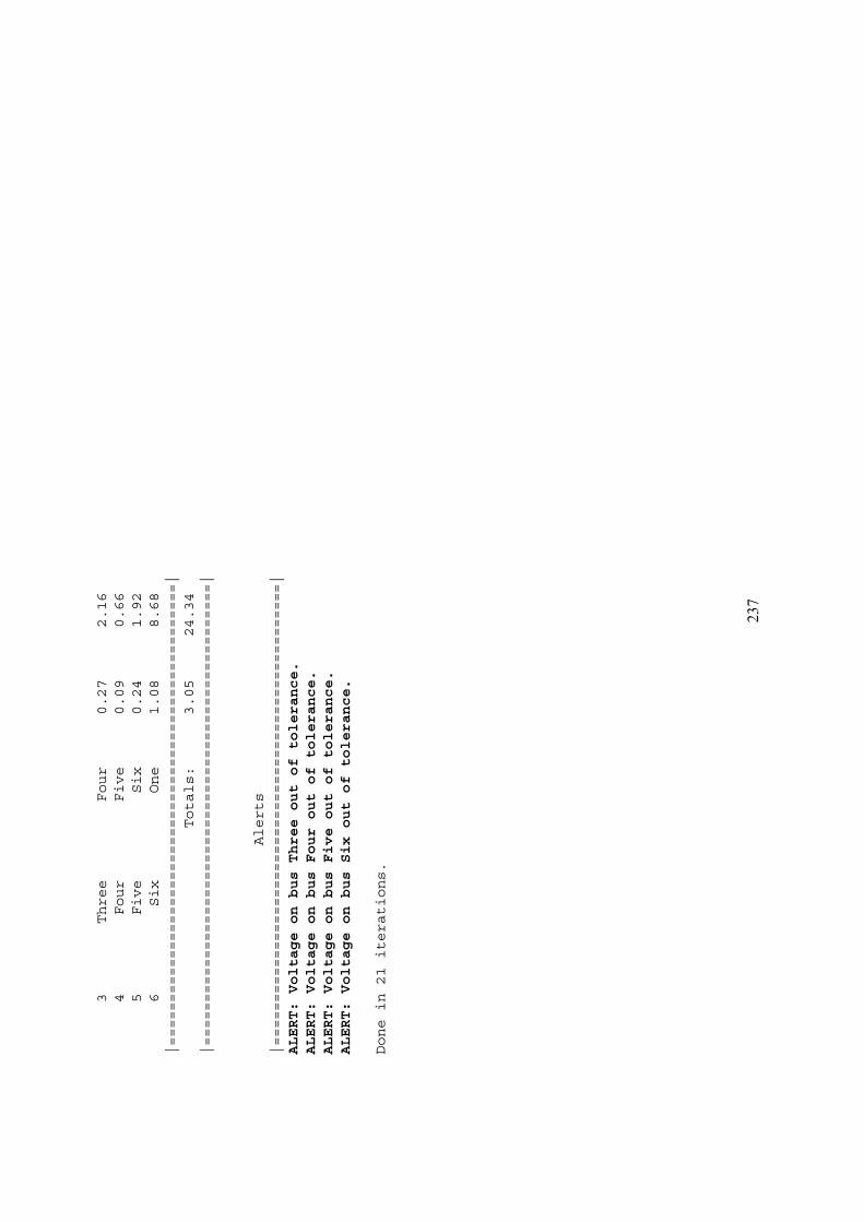
237
3Three
Four
0.27
2.16
4Four
Five
0.09
0.66
5Five
Six
0.24
1.92
6Six
One
1.08
8.68
|=====================================================|
Totals:
3.05
24.34
|=====================================================|
Alerts
|=====================================================|
ALERT:VoltageonbusThreeoutoftolerance.
ALERT:VoltageonbusFouroutoftolerance.
ALERT:VoltageonbusFiveoutoftolerance.
ALERT:VoltageonbusSixoutoftolerance.
Donein21iterations.
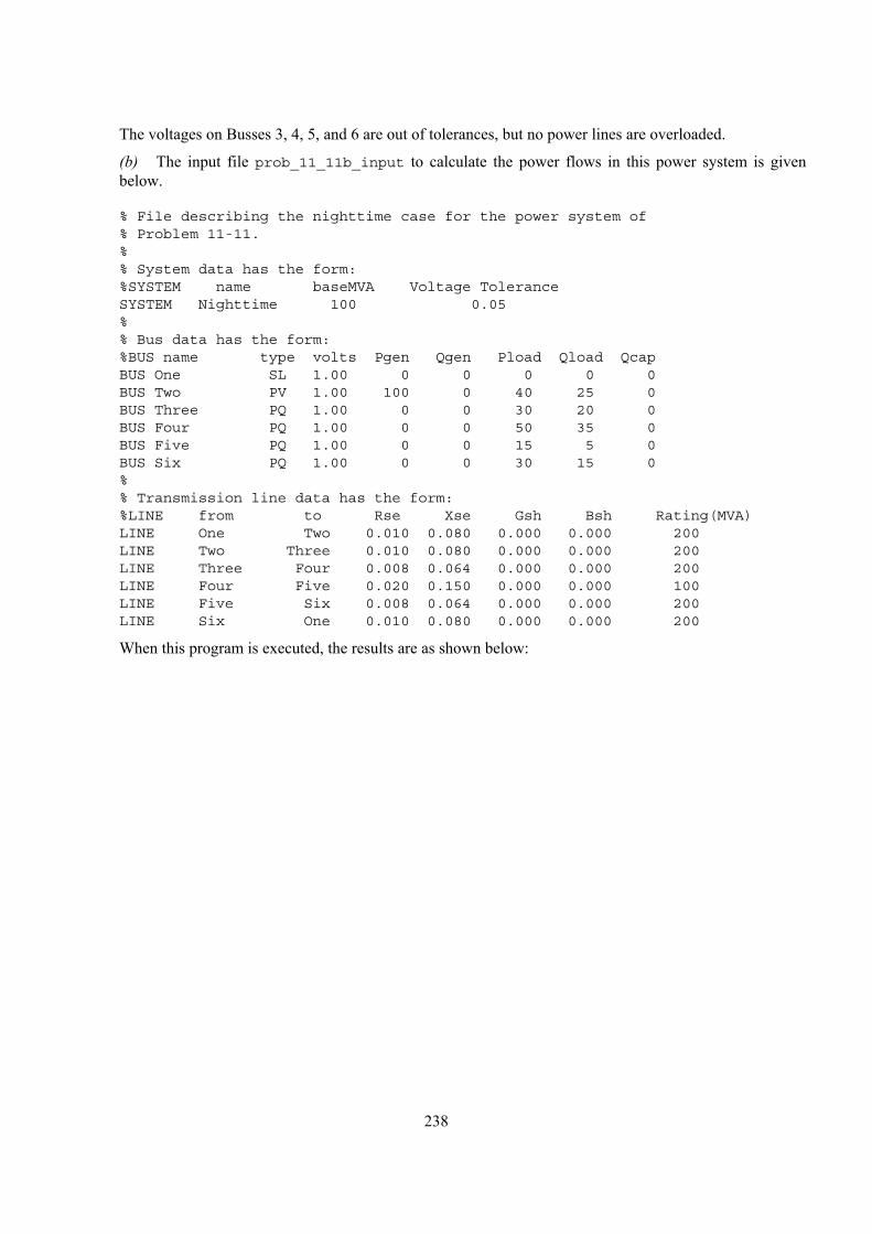
238
The voltages on Busses 3, 4, 5, and 6 are out of tolerances, but no power lines are overloaded.
(b) The input file prob_11_11b_input to calculate the power flows in this power system is given below.
% File describing the nighttime case for the power system of% Problem 11-11.%% System data has the form:%SYSTEM name baseMVA Voltage ToleranceSYSTEM Nighttime 100 0.05%% Bus data has the form:%BUS name type volts Pgen Qgen Pload Qload QcapBUS One SL 1.00 0 0 0 0 0BUS Two PV 1.00 100 0 40 25 0BUS Three PQ 1.00 0 0 30 20 0BUS Four PQ 1.00 0 0 50 35 0BUS Five PQ 1.00 0 0 15 5 0BUS Six PQ 1.00 0 0 30 15 0%% Transmission line data has the form:%LINE from to Rse Xse Gsh Bsh Rating(MVA)LINE One Two 0.010 0.080 0.000 0.000 200LINE Two Three 0.010 0.080 0.000 0.000 200LINE Three Four 0.008 0.064 0.000 0.000 200LINE Four Five 0.020 0.150 0.000 0.000 100LINE Five Six 0.008 0.064 0.000 0.000 200LINE Six One 0.010 0.080 0.000 0.000 200
When this program is executed, the results are as shown below:

239
>>power_flowprob_11_11b_input
Inputsummarystatistics:
24linesinsystemfile
1SYSTEMlines
6BUSlines
6LINElines
ResultsforCaseNighttime
|====================BusInformation=======================================|=======LineInformation======|
Bus
Bus
Volts/angle
|--Generation--|------Load-----|--Cap--|
To
|----LineFlow---|
no.
Name
Type
(pu)
(deg)
(MW)
(MVAR)
(MW)
(MVAR)
(MVAR)
Bus
(MW)
(MVAR)|
|========================================================================================================|
1One
SL
1.000/
0.00
66.25
34.71
0.00
0.00
0.00
Two
7.71
-0.94
Six
58.54
35.65
2Two
PV
1.000/
-0.36
100.00
77.50
40.00
25.00
0.00
One
-7.71
0.99
Three
67.81
51.54
3Three
PQ
0.953/
-3.31
0.00
0.00
30.00
20.00
0.00
Two
-67.09
-45.73
Four
37.20
25.75
4Four
PQ
0.933/
-4.71
0.00
0.00
50.00
35.00
0.00
Three
-37.02
-24.31
Five
-12.95
-10.68
5Five
PQ
0.953/
-3.60
0.00
0.00
15.00
5.00
0.00
Four
13.02
11.17
Six
-27.98
-16.16
6Six
PQ
0.967/
-2.57
0.00
0.00
30.00
15.00
0.00
Five
28.07
16.89
One
-58.07
-31.89
|========================================================================================================|
Totals
166.25
112.21
165.00
100.00
0.00
|========================================================================================================|
LineLosses
|=====================================================|
|Line
From
To
Ploss
Qloss
||
no.
Bus
Bus
(MW)
(MVAR)|
|=====================================================|
1One
Two
0.01
0.05
2Two
Three
0.73
5.80
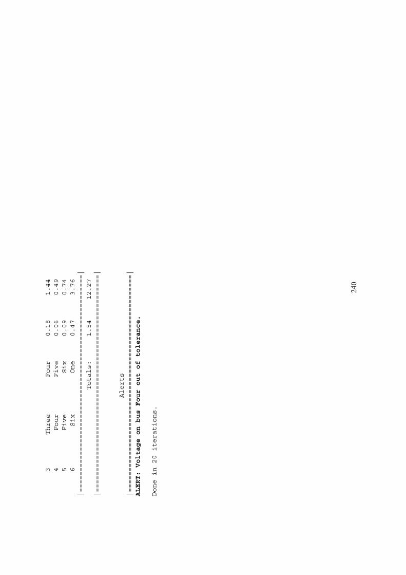
240
3Three
Four
0.18
1.44
4Four
Five
0.06
0.49
5Five
Six
0.09
0.74
6Six
One
0.47
3.76
|=====================================================|
Totals:
1.54
12.27
|=====================================================|
Alerts
|=====================================================|
ALERT:VoltageonbusFouroutoftolerance.
Donein20iterations.
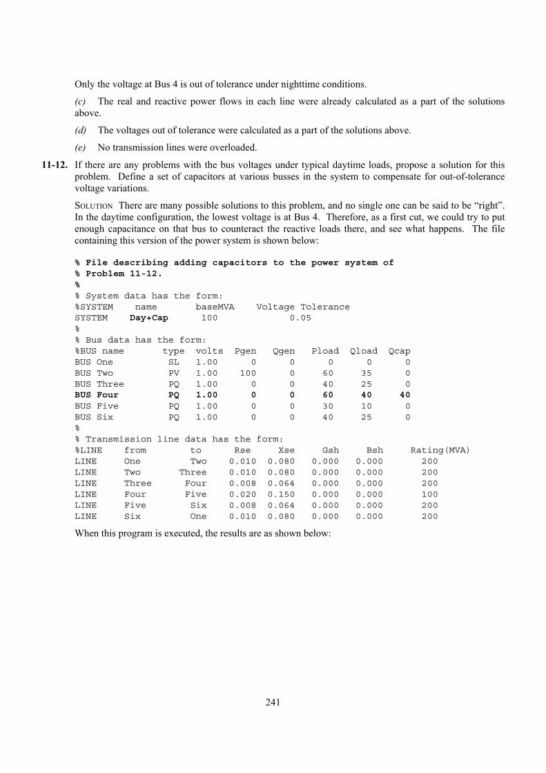
241
Only the voltage at Bus 4 is out of tolerance under nighttime conditions.
(c) The real and reactive power flows in each line were already calculated as a part of the solutions above.
(d) The voltages out of tolerance were calculated as a part of the solutions above.
(e) No transmission lines were overloaded.
11-12. If there are any problems with the bus voltages under typical daytime loads, propose a solution for this problem. Define a set of capacitors at various busses in the system to compensate for out-of-tolerance voltage variations.
SOLUTION There are many possible solutions to this problem, and no single one can be said to be “right”. In the daytime configuration, the lowest voltage is at Bus 4. Therefore, as a first cut, we could try to put enough capacitance on that bus to counteract the reactive loads there, and see what happens. The file containing this version of the power system is shown below:
% File describing adding capacitors to the power system of% Problem 11-12.%% System data has the form:%SYSTEM name baseMVA Voltage ToleranceSYSTEM Day+Cap 100 0.05%% Bus data has the form:%BUS name type volts Pgen Qgen Pload Qload QcapBUS One SL 1.00 0 0 0 0 0BUS Two PV 1.00 100 0 60 35 0BUS Three PQ 1.00 0 0 40 25 0BUS Four PQ 1.00 0 0 60 40 40BUS Five PQ 1.00 0 0 30 10 0BUS Six PQ 1.00 0 0 40 25 0%% Transmission line data has the form:%LINE from to Rse Xse Gsh Bsh Rating(MVA)LINE One Two 0.010 0.080 0.000 0.000 200LINE Two Three 0.010 0.080 0.000 0.000 200LINE Three Four 0.008 0.064 0.000 0.000 200LINE Four Five 0.020 0.150 0.000 0.000 100LINE Five Six 0.008 0.064 0.000 0.000 200LINE Six One 0.010 0.080 0.000 0.000 200
When this program is executed, the results are as shown below:
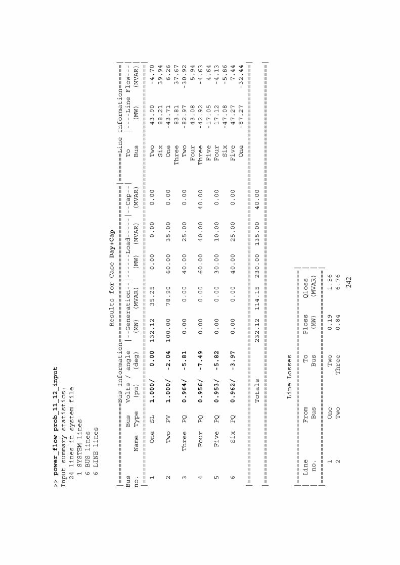
242
>>power_flowprob_11_12_input
Inputsummarystatistics:
24linesinsystemfile
1SYSTEMlines
6BUSlines
6LINElines
ResultsforCaseDay+Cap
|====================BusInformation=======================================|=======LineInformation======|
Bus
Bus
Volts/angle
|--Generation--|------Load-----|--Cap--|
To
|----LineFlow---|
no.
Name
Type
(pu)
(deg)
(MW)
(MVAR)
(MW)
(MVAR)
(MVAR)
Bus
(MW)
(MVAR)|
|========================================================================================================|
1One
SL
1.000/
0.00
132.12
35.25
0.00
0.00
0.00
Two
43.90
-4.70
Six
88.21
39.94
2Two
PV
1.000/
-2.04
100.00
78.90
60.00
35.00
0.00
One
-43.71
6.26
Three
83.81
37.67
3Three
PQ
0.964/
-5.81
0.00
0.00
40.00
25.00
0.00
Two
-82.97
-30.92
Four
43.08
5.94
4Four
PQ
0.956/
-7.49
0.00
0.00
60.00
40.00
40.00
Three
-42.92
-4.63
Five
-17.05
4.64
5Five
PQ
0.953/
-5.82
0.00
0.00
30.00
10.00
0.00
Four
17.12
-4.13
Six
-47.08
-5.86
6Six
PQ
0.962/
-3.97
0.00
0.00
40.00
25.00
0.00
Five
47.27
7.44
One
-87.27
-32.44
|========================================================================================================|
Totals
232.12
114.15
230.00
135.00
40.00
|========================================================================================================|
LineLosses
|=====================================================|
|Line
From
To
Ploss
Qloss
||
no.
Bus
Bus
(MW)
(MVAR)|
|=====================================================|
1One
Two
0.19
1.56
2Two
Three
0.84
6.76
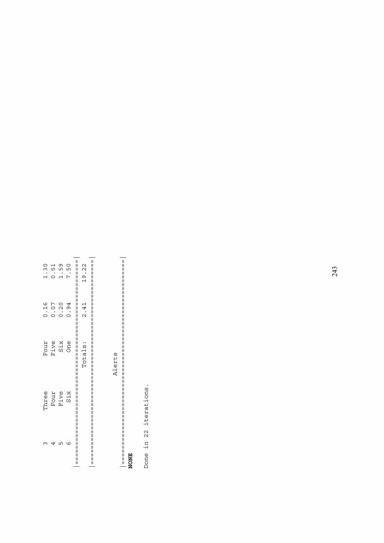
243
3Three
Four
0.16
1.30
4Four
Five
0.07
0.51
5Five
Six
0.20
1.59
6Six
One
0.94
7.50
|=====================================================|
Totals:
2.41
19.22
|=====================================================|
Alerts
|=====================================================|
NONE
Donein22iterations.
244
This choice appears to have worked, since all of the voltages are now in tolerance. However, some of the voltages are pretty marginal—they are just barely in tolerance. Perhaps another solution would be better. Feel free to experiment and see what you come up with.
11-13. What happens to the bus voltages under nighttime conditions of the capacitors proposed in Problem 11-12 are left attached to the system at night? Is it ok to permanently connect the capacitors to the power system, or must they be switched?
SOLUTION As before, there are many “right” answers to this problem. If the same 40 MVAR capacitive load is added to Bus 4 and night, the resulting power system file is:
% File describing the nighttime case for the power system of% Problem 11-13.%% System data has the form:%SYSTEM name baseMVA Voltage ToleranceSYSTEM Night+Cap 100 0.05%% Bus data has the form:%BUS name type volts Pgen Qgen Pload Qload QcapBUS One SL 1.00 0 0 0 0 0BUS Two PV 1.00 100 0 40 25 0BUS Three PQ 1.00 0 0 30 20 0BUS Four PQ 1.00 0 0 50 35 40BUS Five PQ 1.00 0 0 15 5 0BUS Six PQ 1.00 0 0 30 15 0%% Transmission line data has the form:%LINE from to Rse Xse Gsh Bsh Rating(MVA)LINE One Two 0.010 0.080 0.000 0.000 200LINE Two Three 0.010 0.080 0.000 0.000 200LINE Three Four 0.008 0.064 0.000 0.000 200LINE Four Five 0.020 0.150 0.000 0.000 100LINE Five Six 0.008 0.064 0.000 0.000 200LINE Six One 0.010 0.080 0.000 0.000 200
When this program is executed, the results are as shown below:

245
>>power_flowprob_11_13_input
Inputsummarystatistics:
24linesinsystemfile
1SYSTEMlines
6BUSlines
6LINElines
ResultsforCaseNight+Cap
|====================BusInformation=======================================|=======LineInformation======|
Bus
Bus
Volts/angle
|--Generation--|------Load-----|--Cap--|
To
|----LineFlow---|
no.
Name
Type
(pu)
(deg)
(MW)
(MVAR)
(MW)
(MVAR)
(MVAR)
Bus
(MW)
(MVAR)|
|========================================================================================================|
1One
SL
1.000/
0.00
65.79
20.43
0.00
0.00
0.00
Two
7.58
-0.92
Six
58.20
21.35
2Two
PV
1.000/
-0.35
100.00
48.45
40.00
25.00
0.00
One
-7.58
0.97
Three
67.70
22.50
3Three
PQ
0.977/
-3.40
0.00
0.00
30.00
20.00
0.00
Two
-67.19
-18.43
Four
37.32
-1.56
4Four
PQ
0.975/
-4.84
0.00
0.00
50.00
35.00
40.00
Three
-37.20
2.50
Five
-12.76
2.51
5Five
PQ
0.974/
-3.66
0.00
0.00
15.00
5.00
0.00
Four
12.80
-2.24
Six
-27.75
-2.75
6Six
PQ
0.978/
-2.60
0.00
0.00
30.00
15.00
0.00
Five
27.82
3.28
One
-57.82
-18.28
|========================================================================================================|
Totals
165.79
68.87
165.00
100.00
40.00
|========================================================================================================|
LineLosses
|=====================================================|
|Line
From
To
Ploss
Qloss
||
no.
Bus
Bus
(MW)
(MVAR)|
|=====================================================|
1One
Two
0.01
0.05
2Two
Three
0.51
4.07

246
3Three
Four
0.12
0.94
4Four
Five
0.04
0.27
5Five
Six
0.07
0.52
6Six
One
0.38
3.07
|=====================================================|
Totals:
1.12
8.92
|=====================================================|
Alerts
|=====================================================|
NONE
Donein20iterations.
247
In the case that we created in Problem 11-12, the capacitors required for daytime voltage correction could be left in for the typical nighttime load. This is not always the case. If you made a different assumption about the size and distribution of capacitors in Problem 11-12, you might need to switch some or all of the capacitors out ant night. Also, if the nighttime loads can fall well below the “typical” nighttime levels, you might need to switch some capacitors out.
11-14. Suppose that the power system is operating under typical daytime loads, and the transmission line between Bus 4 and Bus 5 open circuits. What happens to the voltages on each bus now? Are any of the transmission lines overloaded?
SOLUTION In this case, we will start with the typical daytime loads, and remove the transmission line between Busses 4 and 5. The resulting input file is shown below:
% File describing the case where the line between busses% 4 and 5 open circuits.%% System data has the form:%SYSTEM name baseMVA Voltage ToleranceSYSTEM Open_line 100 0.05%% Bus data has the form:%BUS name type volts Pgen Qgen Pload Qload QcapBUS One SL 1.00 0 0 0 0 0BUS Two PV 1.00 100 0 60 35 0BUS Three PQ 1.00 0 0 40 25 0BUS Four PQ 1.00 0 0 60 40 0BUS Five PQ 1.00 0 0 30 10 0BUS Six PQ 1.00 0 0 40 25 0%% Transmission line data has the form:%LINE from to Rse Xse Gsh Bsh Rating(MVA)LINE One Two 0.010 0.080 0.000 0.000 200LINE Two Three 0.010 0.080 0.000 0.000 200LINE Three Four 0.008 0.064 0.000 0.000 200%LINE Four Five 0.020 0.150 0.000 0.000 100LINE Five Six 0.008 0.064 0.000 0.000 200LINE Six One 0.010 0.080 0.000 0.000 200
When this program is executed, the results are as shown below:
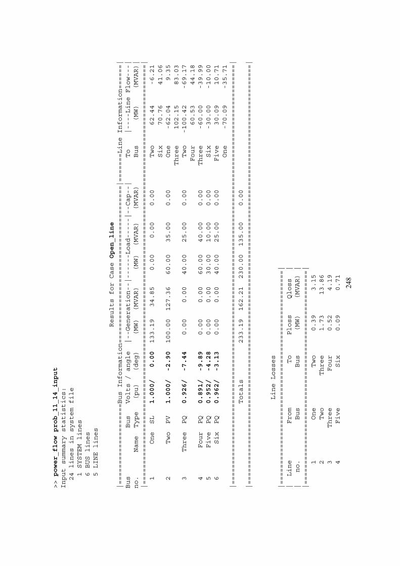
248
>>power_flowprob_11_14_input
Inputsummarystatistics:
24linesinsystemfile
1SYSTEMlines
6BUSlines
5LINElines
ResultsforCaseOpen_line
|====================BusInformation=======================================|=======LineInformation======|
Bus
Bus
Volts/angle
|--Generation--|------Load-----|--Cap--|
To
|----LineFlow---|
no.
Name
Type
(pu)
(deg)
(MW)
(MVAR)
(MW)
(MVAR)
(MVAR)
Bus
(MW)
(MVAR)|
|========================================================================================================|
1One
SL
1.000/
0.00
133.19
34.85
0.00
0.00
0.00
Two
62.44
-6.21
Six
70.76
41.06
2Two
PV
1.000/
-2.90
100.00
127.36
60.00
35.00
0.00
One
-62.04
9.35
Three
102.15
83.03
3Three
PQ
0.926/
-7.44
0.00
0.00
40.00
25.00
0.00
Two
-100.42
-69.17
Four
60.53
44.18
4Four
PQ
0.891/
-9.89
0.00
0.00
60.00
40.00
0.00
Three
-60.00
-39.99
5Five
PQ
0.952/
-4.28
0.00
0.00
30.00
10.00
0.00
Six
-30.00
-10.00
6Six
PQ
0.962/
-3.13
0.00
0.00
40.00
25.00
0.00
Five
30.09
10.71
One
-70.09
-35.71
|========================================================================================================|
Totals
233.19
162.21
230.00
135.00
0.00
|========================================================================================================|
LineLosses
|=====================================================|
|Line
From
To
Ploss
Qloss
||
no.
Bus
Bus
(MW)
(MVAR)|
|=====================================================|
1One
Two
0.39
3.15
2Two
Three
1.73
13.86
3Three
Four
0.52
4.19
4Five
Six
0.09
0.71
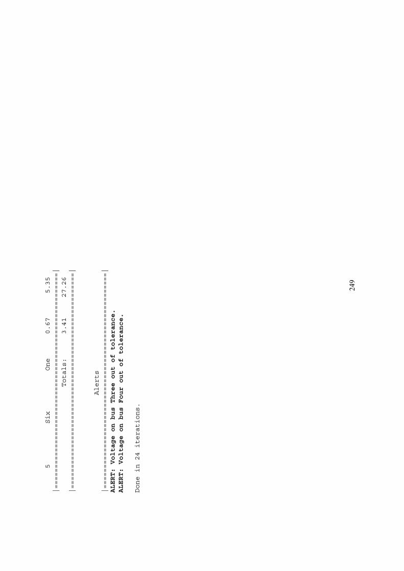
249
5Six
One
0.67
5.35
|=====================================================|
Totals:
3.41
27.26
|=====================================================|
Alerts
|=====================================================|
ALERT:VoltageonbusThreeoutoftolerance.
ALERT:VoltageonbusFouroutoftolerance.
Donein24iterations.
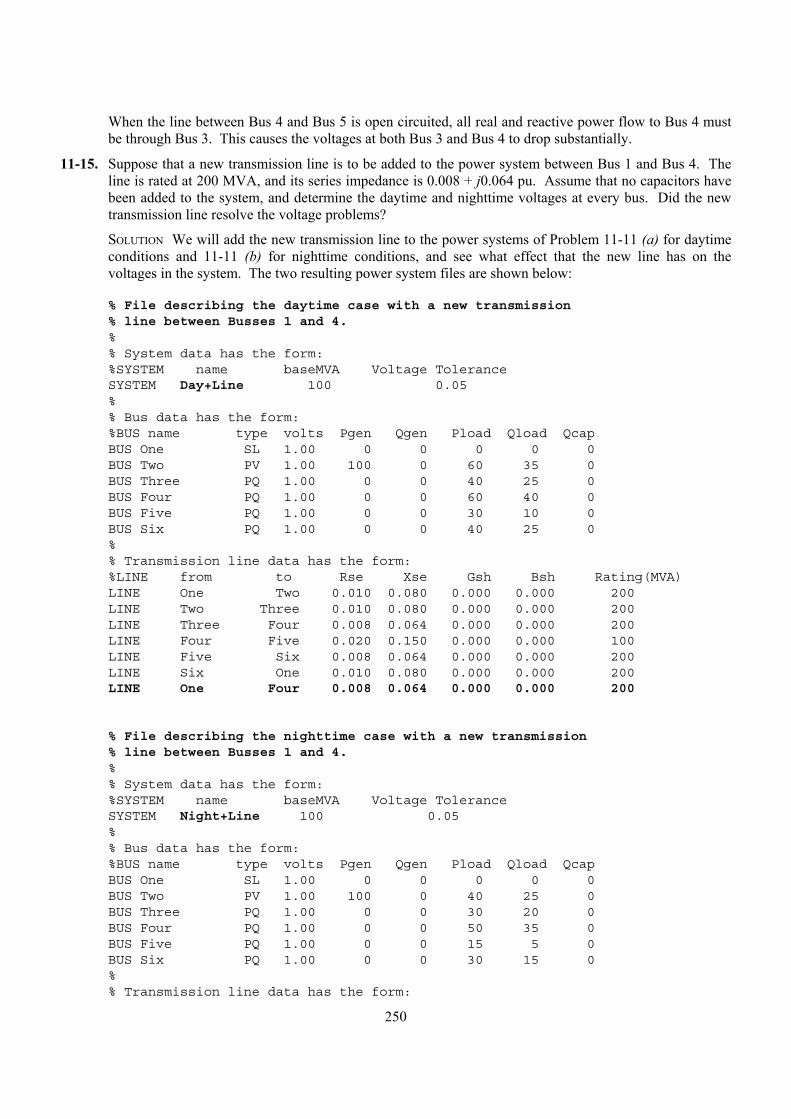
250
When the line between Bus 4 and Bus 5 is open circuited, all real and reactive power flow to Bus 4 must be through Bus 3. This causes the voltages at both Bus 3 and Bus 4 to drop substantially.
11-15. Suppose that a new transmission line is to be added to the power system between Bus 1 and Bus 4. The line is rated at 200 MVA, and its series impedance is 0.008 + j0.064 pu. Assume that no capacitors have been added to the system, and determine the daytime and nighttime voltages at every bus. Did the new transmission line resolve the voltage problems?
SOLUTION We will add the new transmission line to the power systems of Problem 11-11 (a) for daytime conditions and 11-11 (b) for nighttime conditions, and see what effect that the new line has on the voltages in the system. The two resulting power system files are shown below:
% File describing the daytime case with a new transmission% line between Busses 1 and 4.%% System data has the form:%SYSTEM name baseMVA Voltage ToleranceSYSTEM Day+Line 100 0.05%% Bus data has the form:%BUS name type volts Pgen Qgen Pload Qload QcapBUS One SL 1.00 0 0 0 0 0BUS Two PV 1.00 100 0 60 35 0BUS Three PQ 1.00 0 0 40 25 0BUS Four PQ 1.00 0 0 60 40 0BUS Five PQ 1.00 0 0 30 10 0BUS Six PQ 1.00 0 0 40 25 0%% Transmission line data has the form:%LINE from to Rse Xse Gsh Bsh Rating(MVA)LINE One Two 0.010 0.080 0.000 0.000 200LINE Two Three 0.010 0.080 0.000 0.000 200LINE Three Four 0.008 0.064 0.000 0.000 200LINE Four Five 0.020 0.150 0.000 0.000 100LINE Five Six 0.008 0.064 0.000 0.000 200LINE Six One 0.010 0.080 0.000 0.000 200LINE One Four 0.008 0.064 0.000 0.000 200
% File describing the nighttime case with a new transmission% line between Busses 1 and 4.%% System data has the form:%SYSTEM name baseMVA Voltage ToleranceSYSTEM Night+Line 100 0.05%% Bus data has the form:%BUS name type volts Pgen Qgen Pload Qload QcapBUS One SL 1.00 0 0 0 0 0BUS Two PV 1.00 100 0 40 25 0BUS Three PQ 1.00 0 0 30 20 0BUS Four PQ 1.00 0 0 50 35 0BUS Five PQ 1.00 0 0 15 5 0BUS Six PQ 1.00 0 0 30 15 0%% Transmission line data has the form:

251
%LINE from to Rse Xse Gsh Bsh Rating(MVA)LINE One Two 0.010 0.080 0.000 0.000 200LINE Two Three 0.010 0.080 0.000 0.000 200LINE Three Four 0.008 0.064 0.000 0.000 200LINE Four Five 0.020 0.150 0.000 0.000 100LINE Five Six 0.008 0.064 0.000 0.000 200LINE Six One 0.010 0.080 0.000 0.000 200LINE One Four 0.008 0.064 0.000 0.000 200
When these programs are executed, the results are as shown below:
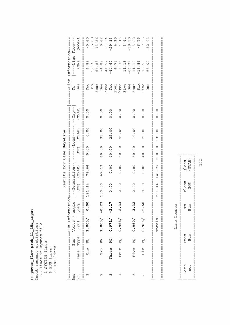
252
>>power_flowprob_11_15a_input
Inputsummarystatistics:
25linesinsystemfile
1SYSTEMlines
6BUSlines
7LINElines
ResultsforCaseDay+Line
|====================BusInformation=======================================|=======LineInformation======|
Bus
Bus
Volts/angle
|--Generation--|------Load-----|--Cap--|
To
|----LineFlow---|
no.
Name
Type
(pu)
(deg)
(MW)
(MVAR)
(MW)
(MVAR)
(MVAR)
Bus
(MW)
(MVAR)|
|========================================================================================================|
1One
SL
1.000/
0.00
131.14
78.64
0.00
0.00
0.00
Two
4.89
-0.60
Six
59.38
35.88
Four
66.88
43.36
2Two
PV
1.000/
-0.23
100.00
67.13
60.00
35.00
0.00
One
-4.88
0.62
Three
44.97
31.54
3Three
PQ
0.971/
-2.17
0.00
0.00
40.00
25.00
0.00
Two
-44.67
-29.13
Four
4.73
4.15
4Four
PQ
0.968/
-2.33
0.00
0.00
60.00
40.00
0.00
Three
-4.73
-4.13
Five
11.13
3.44
One
-66.37
-39.30
5Five
PQ
0.960/
-3.32
0.00
0.00
30.00
10.00
0.00
Four
-11.10
-3.22
Six
-18.86
-6.75
6Six
PQ
0.966/
-2.60
0.00
0.00
40.00
25.00
0.00
Five
18.90
7.03
One
-58.90
-32.03
|========================================================================================================|
Totals
231.14
145.77
230.00
135.00
0.00
|========================================================================================================|
LineLosses
|=====================================================|
|Line
From
To
Ploss
Qloss
||
no.
Bus
Bus
(MW)
(MVAR)|
|=====================================================|
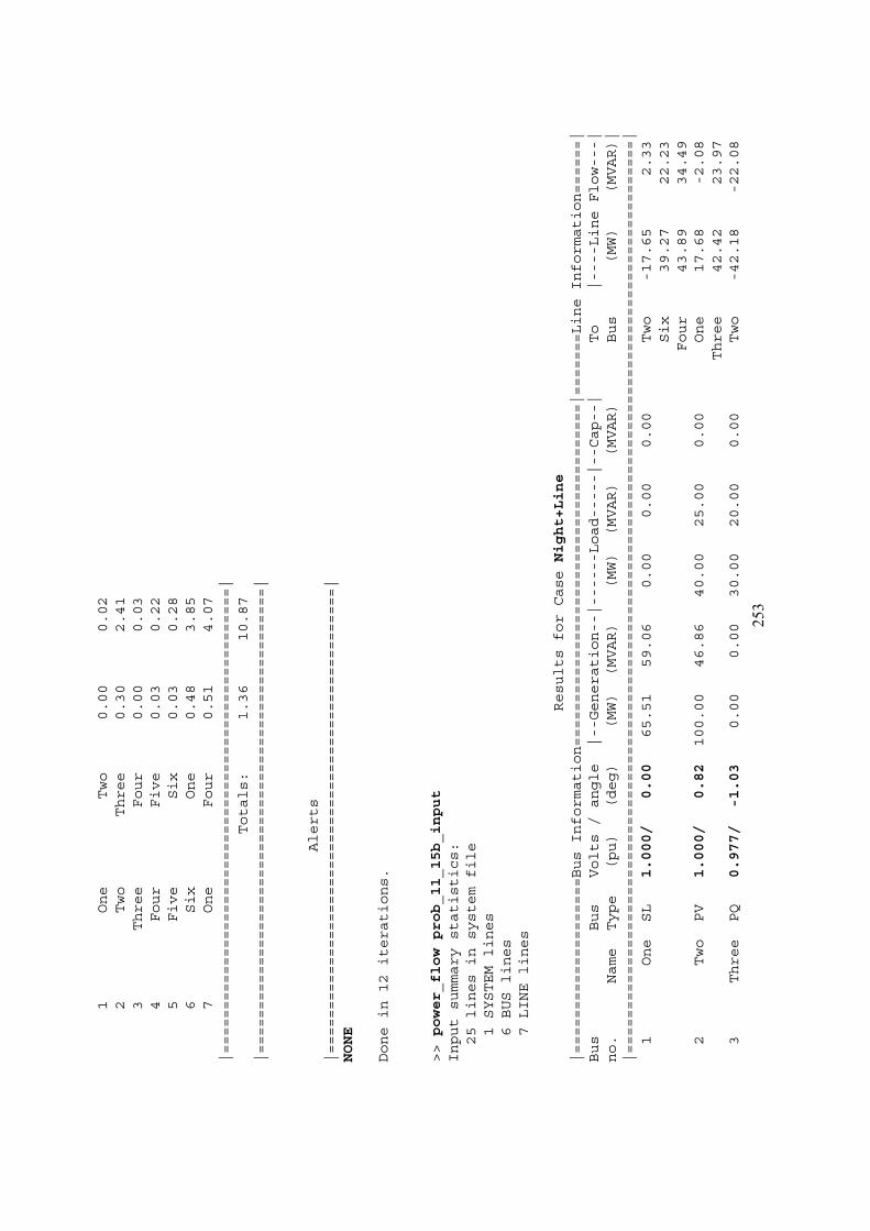
253
1One
Two
0.00
0.02
2Two
Three
0.30
2.41
3Three
Four
0.00
0.03
4Four
Five
0.03
0.22
5Five
Six
0.03
0.28
6Six
One
0.48
3.85
7One
Four
0.51
4.07
|=====================================================|
Totals:
1.36
10.87
|=====================================================|
Alerts
|=====================================================|
NONE
Donein12iterations.
>>power_flowprob_11_15b_input
Inputsummarystatistics:
25linesinsystemfile
1SYSTEMlines
6BUSlines
7LINElines
ResultsforCaseNight+Line
|====================BusInformation=======================================|=======LineInformation======|
Bus
Bus
Volts/angle
|--Generation--|------Load-----|--Cap--|
To
|----LineFlow---|
no.
Name
Type
(pu)
(deg)
(MW)
(MVAR)
(MW)
(MVAR)
(MVAR)
Bus
(MW)
(MVAR)|
|========================================================================================================|
1One
SL
1.000/
0.00
65.51
59.06
0.00
0.00
0.00
Two
-17.65
2.33
Six
39.27
22.23
Four
43.89
34.49
2Two
PV
1.000/
0.82
100.00
46.86
40.00
25.00
0.00
One
17.68
-2.08
Three
42.42
23.97
3Three
PQ
0.977/
-1.03
0.00
0.00
30.00
20.00
0.00
Two
-42.18
-22.08
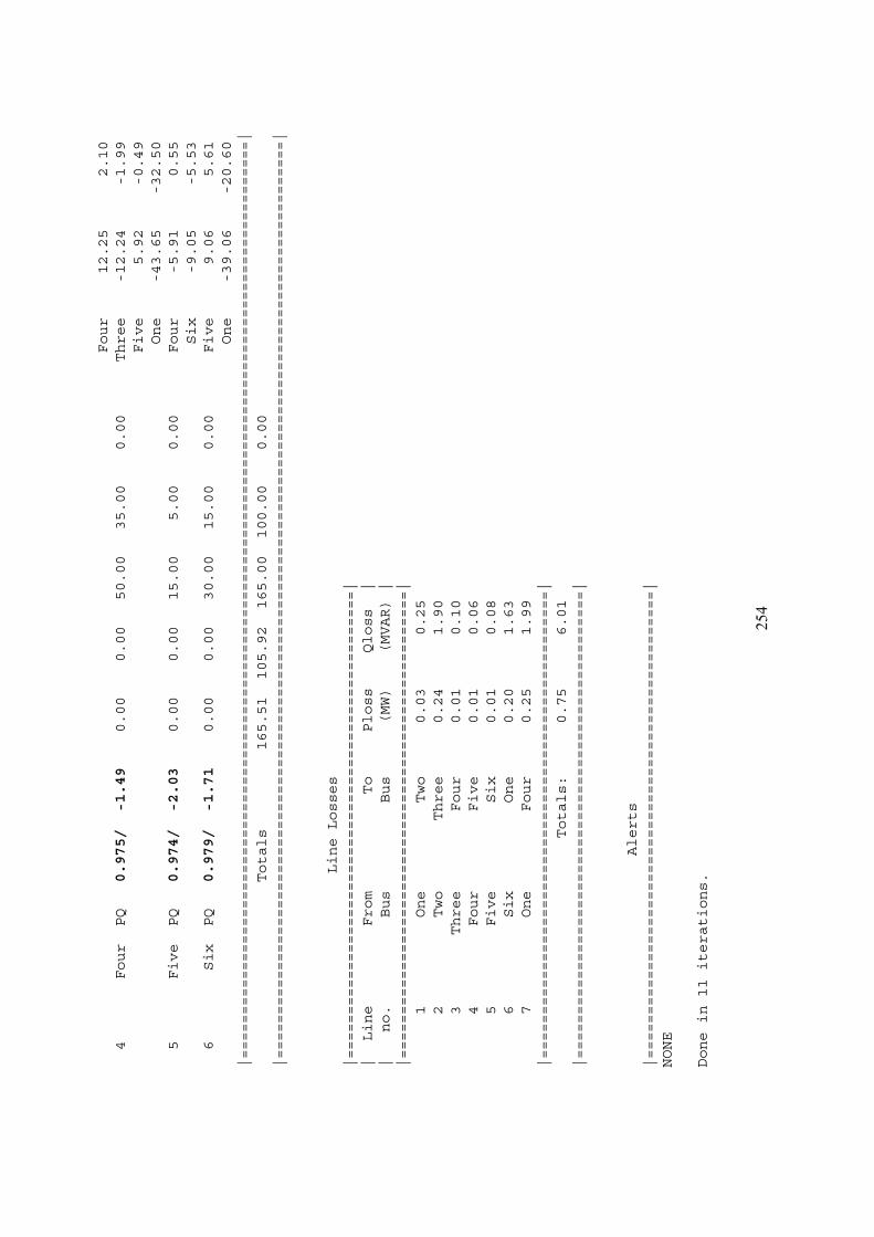
254
Four
12.25
2.10
4Four
PQ
0.975/
-1.49
0.00
0.00
50.00
35.00
0.00
Three
-12.24
-1.99
Five
5.92
-0.49
One
-43.65
-32.50
5Five
PQ
0.974/
-2.03
0.00
0.00
15.00
5.00
0.00
Four
-5.91
0.55
Six
-9.05
-5.53
6Six
PQ
0.979/
-1.71
0.00
0.00
30.00
15.00
0.00
Five
9.06
5.61
One
-39.06
-20.60
|========================================================================================================|
Totals
165.51
105.92
165.00
100.00
0.00
|========================================================================================================|
LineLosses
|=====================================================|
|Line
From
To
Ploss
Qloss
||
no.
Bus
Bus
(MW)
(MVAR)|
|=====================================================|
1One
Two
0.03
0.25
2Two
Three
0.24
1.90
3Three
Four
0.01
0.10
4Four
Five
0.01
0.06
5Five
Six
0.01
0.08
6Six
One
0.20
1.63
7One
Four
0.25
1.99
|=====================================================|
Totals:
0.75
6.01
|=====================================================|
Alerts
|=====================================================|
NONE
Donein11iterations.

255
For both daytime and nighttime cases, the addition of the new transmission line made significant improvements in the voltages at each bus. Now the voltages are in tolerance day or night, and no transmission lines are overloaded day or night.
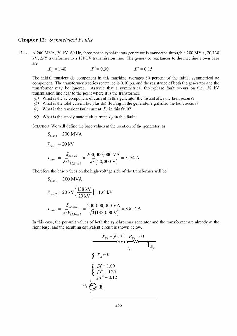
256
Chapter 12: Symmetrical Faults
12-1. A 200 MVA, 20 kV, 60 Hz, three-phase synchronous generator is connected through a 200 MVA, 20/138 kV, ∆-Y transformer to a 138 kV transmission line. The generator reactances to the machine’s own base are
1.40SX = 0.30X ′ = 0.15X ′′ =
The initial transient dc component in this machine averages 50 percent of the initial symmetrical ac component. The transformer’s series reactance is 0.10 pu, and the resistance of both the generator and the transformer may be ignored. Assume that a symmetrical three-phase fault occurs on the 138 kV transmission line near to the point where it is the transformer. (a) What is the ac component of current in this generator the instant after the fault occurs? (b) What is the total current (ac plus dc) flowing in the generator right after the fault occurs? (c) What is the transient fault current fI ′ in this fault?
(d) What is the steady-state fault current fI in this fault?
SOLUTION We will define the base values at the location of the generator. as
base,1 200 MVAS =
base,1 20 kVV =
( )
3 ,basebase,1
,base 1
200,000,000 VA 5774 A3 3 20,000 VLL
SI
Vφ= = =
Therefore the base values on the high-voltage side of the transformer will be
base,2 200 MVAS =
base,2138 kV20 kV 138 kV20 kV
V = =
( )
3 ,basebase,2
,base 2
200,000,000 VA 836.7 A3 3 138,000 VLL
SI
Vφ= = =
In this case, the per-unit values of both the synchronous generator and the transformer are already at the right base, and the resulting equivalent circuit is shown below.
+
-
G1
T1If
RA ≈ 0
RT1 ≈ 0XT1 = j0.10
jX = 1.00jX' = 0.25jX" = 0.12
EA
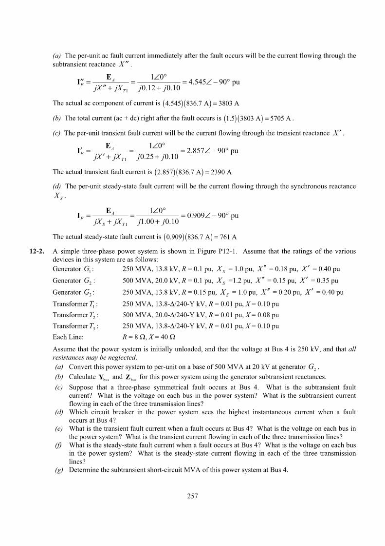
257
(a) The per-unit ac fault current immediately after the fault occurs will be the current flowing through the subtransient reactance X ′′ .
1
1 0 4.545 90 pu0.12 0.10
AF
TjX jX j j∠ °= = = ∠ − °′′
+ +′′EI
The actual ac component of current is ( ) ( )4.545 836.7 A 3803 A=
(b) The total current (ac + dc) right after the fault occurs is ( ) ( )1.5 3803 A 5705 A= .
(c) The per-unit transient fault current will be the current flowing through the transient reactance X ′ .
1
1 0 2.857 90 pu0.25 0.10
AF
TjX jX j j∠ °= = = ∠ − °′
+ +′EI
The actual transient fault current is ( ) ( )2.857 836.7 A 2390 A=
(d) The per-unit steady-state fault current will be the current flowing through the synchronous reactance SX .
1
1 0 0.909 90 pu1.00 0.10
AF
S TjX jX j j∠ °= = = ∠ − °
+ +EI
The actual steady-state fault current is ( ) ( )0.909 836.7 A 761 A=
12-2. A simple three-phase power system is shown in Figure P12-1. Assume that the ratings of the various devices in this system are as follows:
Generator 1G : 250 MVA, 13.8 kV, R = 0.1 pu, SX = 1.0 pu, X ′′ = 0.18 pu, X ′ = 0.40 pu Generator 2G : 500 MVA, 20.0 kV, R = 0.1 pu, SX =1.2 pu, X ′′ = 0.15 pu, X ′ = 0.35 pu Generator 3G : 250 MVA, 13.8 kV, R = 0.15 pu, SX = 1.0 pu, X ′′ = 0.20 pu, X ′ = 0.40 pu Transformer 1T : 250 MVA, 13.8-∆/240-Y kV, R = 0.01 pu, X = 0.10 pu Transformer 2T : 500 MVA, 20.0-∆/240-Y kV, R = 0.01 pu, X = 0.08 pu Transformer 3T : 250 MVA, 13.8-∆/240-Y kV, R = 0.01 pu, X = 0.10 pu Each Line: R = 8 Ω, X = 40 Ω
Assume that the power system is initially unloaded, and that the voltage at Bus 4 is 250 kV, and that all resistances may be neglected. (a) Convert this power system to per-unit on a base of 500 MVA at 20 kV at generator 2G . (b) Calculate busY and busZ for this power system using the generator subtransient reactances. (c) Suppose that a three-phase symmetrical fault occurs at Bus 4. What is the subtransient fault
current? What is the voltage on each bus in the power system? What is the subtransient current flowing in each of the three transmission lines?
(d) Which circuit breaker in the power system sees the highest instantaneous current when a fault occurs at Bus 4?
(e) What is the transient fault current when a fault occurs at Bus 4? What is the voltage on each bus in the power system? What is the transient current flowing in each of the three transmission lines?
(f) What is the steady-state fault current when a fault occurs at Bus 4? What is the voltage on each bus in the power system? What is the steady-state current flowing in each of the three transmission lines?
(g) Determine the subtransient short-circuit MVA of this power system at Bus 4.
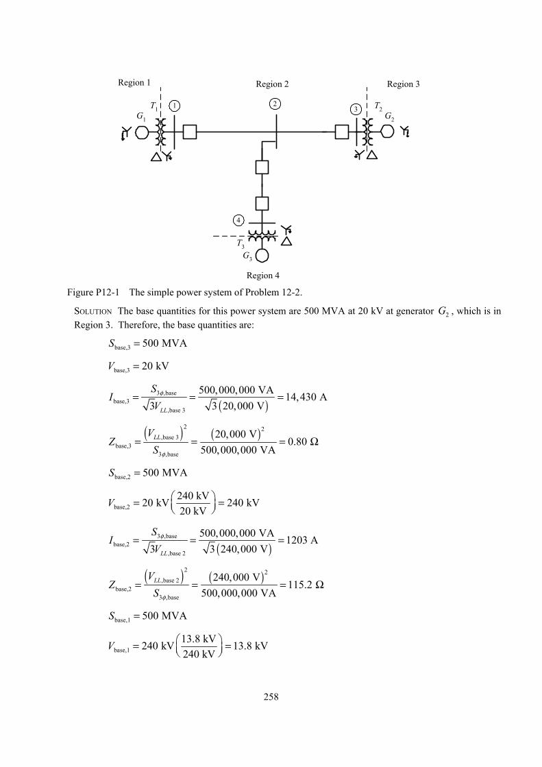
258
1 23
4
G3
T3
G2
T2G1
T1
Region 1 Region 2 Region 3
Region 4
Figure P12-1 The simple power system of Problem 12-2.
SOLUTION The base quantities for this power system are 500 MVA at 20 kV at generator 2G , which is in Region 3. Therefore, the base quantities are:
base,3 500 MVAS =
base,3 20 kVV =
( )
3 ,basebase,3
,base 3
500,000,000 VA 14,430 A3 3 20,000 VLL
SI
Vφ= = =
( ) ( )
2 2,base 3
base,33 ,base
20,000 V0.80
500,000,000 VALLV
ZS φ
= = = Ω
base,2 500 MVAS =
base,2240 kV20 kV 240 kV20 kV
V = =
( )
3 ,basebase,2
,base 2
500,000,000 VA 1203 A3 3 240,000 VLL
SI
Vφ= = =
( ) ( )
2 2,base 2
base,23 ,base
240,000 V115.2
500,000,000 VALLV
ZS φ
= = = Ω
base,1 500 MVAS =
base,113.8 kV240 kV 13.8 kV240 kV
V = =
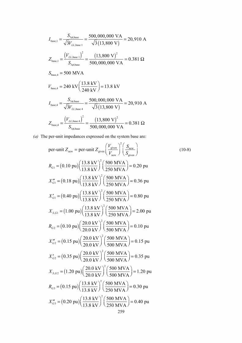
259
( )
3 ,basebase,1
,base 1
500,000,000 VA 20,910 A3 3 13,800 VLL
SI
Vφ= = =
( ) ( )
2 2,base 1
base,13 ,base
13,800 V0.381
500,000,000 VALLV
ZS φ
= = = Ω
base,4 500 MVAS =
base,413.8 kV240 kV 13.8 kV240 kV
V = =
( )
3 ,basebase,4
,base 4
500,000,000 VA 20,910 A3 3 13,800 VLL
SI
Vφ= = =
( ) ( )
2 2,base 4
base,43 ,base
13,800 V0.381
500,000,000 VALLV
ZS φ
= = = Ω
(a) The per-unit impedances expressed on the system base are:
2
given newnew given
new given
per-unit per-unit V SZ ZV S
=
(10-8)
( )2
113.8 kV 500 MVA0.10 pu 0.20 pu13.8 kV 250 MVAGR = =
( )2
113.8 kV 500 MVA0.18 pu 0.36 pu13.8 kV 250 MVAGX = =′′
( )2
113.8 kV 500 MVA0.40 pu 0.80 pu13.8 kV 250 MVAGX = =′
( )2
, 113.8 kV 500 MVA1.00 pu 2.00 pu13.8 kV 250 MVAS GX = =
( )2
220.0 kV 500 MVA0.10 pu 0.10 pu20.0 kV 500 MVAGR = =
( )2
220.0 kV 500 MVA0.15 pu 0.15 pu20.0 kV 500 MVAGX = =′′
( )2
220.0 kV 500 MVA0.35 pu 0.35 pu20.0 kV 500 MVAGX = =′
( )2
, 220.0 kV 500 MVA1.20 pu 1.20 pu20.0 kV 500 MVAS GX = =
( )2
313.8 kV 500 MVA0.15 pu 0.30 pu13.8 kV 250 MVAGR = =
( )2
313.8 kV 500 MVA0.20 pu 0.40 pu13.8 kV 250 MVAGX = =′′
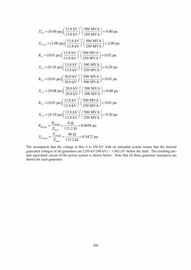
260
( )2
313.8 kV 500 MVA0.40 pu 0.80 pu13.8 kV 250 MVAGX = =′
( )2
, 313.8 kV 500 MVA1.00 pu 2.00 pu13.8 kV 250 MVAS GX = =
( )2
113.8 kV 500 MVA0.01 pu 0.02 pu13.8 kV 250 MVATR = =
( )2
113.8 kV 500 MVA0.10 pu 0.20 pu13.8 kV 250 MVATX = =
( )2
220.0 kV 500 MVA0.01 pu 0.01 pu20.0 kV 500 MVATR = =
( )2
220.0 kV 500 MVA0.08 pu 0.08 pu20.0 kV 500 MVATX = =
( )2
313.8 kV 500 MVA0.01 pu 0.02 pu13.8 kV 250 MVATR = =
( )2
313.8 kV 500 MVA0.10 pu 0.20 pu13.8 kV 250 MVATX = =
line,line,pu
base
8 0.0694 pu115.2
RR
ZΩ Ω= = =
Ω
line,line,pu
base
40 0.3472 pu115.2
XX
ZΩ Ω= = =
Ω
The assumption that the voltage at Bus 4 is 250 kV with an unloaded system means that the internal generated voltages of all generators are (250 kV/240 kV) = 1.042∠0° before the fault. The resulting per-unit equivalent circuit of the power system is shown below. Note that all three generator reactances are shown for each generator.
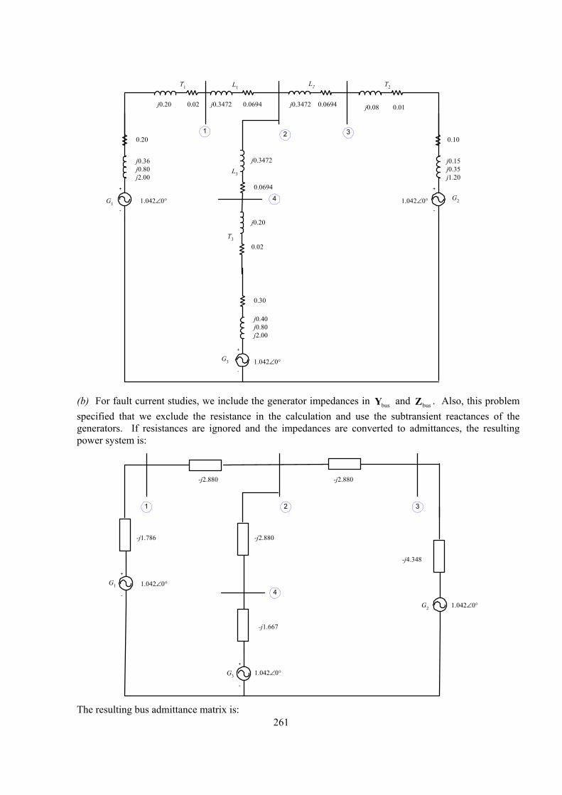
261
+
-
G1
0.20
j0.36j0.80j2.00
L1T1
j0.3472
0.30
T2
+
-
G2
0.10
j0.15j0.35j1.20
L3
+
-
G3
T3
0.0694
L2
j0.3472
j0.3472 0.06940.06940.02
j0.40j0.80j2.00
j0.20 j0.08 0.01
1.042∠0°
1.042∠0°
1.042∠0°
1
4
32
0.02
j0.20
(b) For fault current studies, we include the generator impedances in busY and busZ . Also, this problem
specified that we exclude the resistance in the calculation and use the subtransient reactances of the generators. If resistances are ignored and the impedances are converted to admittances, the resulting power system is:
+
-
G3
-j1.786
1.042∠0°
1.042∠0°
1
4
32
+
-
G1
G2 1.042∠0°
-j2.880
-j2.880
-j1.667
-j4.348
-j2.880
The resulting bus admittance matrix is:
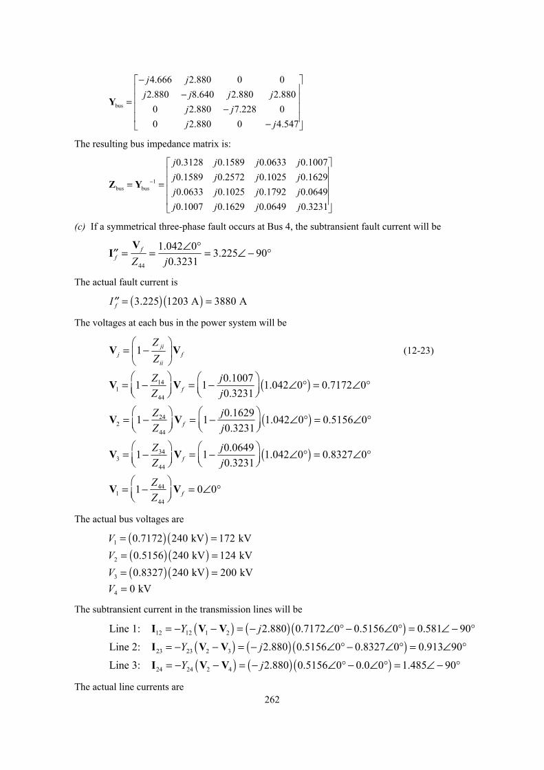
262
bus
4.666 2.880 0 02.880 8.640 2.880 2.880
0 2.880 7.228 00 2.880 0 4.547
j jj j j j
j jj j
− − = − −
Y
The resulting bus impedance matrix is:
1bus bus
0.3128 0.1589 0.0633 0.10070.1589 0.2572 0.1025 0.16290.0633 0.1025 0.1792 0.06490.1007 0.1629 0.0649 0.3231
j j j jj j j jj j j jj j j j
−
= =
Z Y
(c) If a symmetrical three-phase fault occurs at Bus 4, the subtransient fault current will be
44
1.042 0 3.225 900.3231
ff Z j
∠ °= = = ∠ − °′′V
I
The actual fault current is
( ) ( )3.225 1203 A 3880 AfI = =′′
The voltages at each bus in the power system will be
1 jij f
ii
ZZ
= −
V V (12-23)
( )141
44
0.10071 1 1.042 0 0.7172 00.3231f
Z jZ j
= − = − ∠ ° = ∠ °
V V
( )242
44
0.16291 1 1.042 0 0.5156 00.3231f
Z jZ j
= − = − ∠ ° = ∠ °
V V
( )343
44
0.06491 1 1.042 0 0.8327 00.3231f
Z jZ j
= − = − ∠ ° = ∠ °
V V
441
44
1 0 0fZZ
= − = ∠ °
V V
The actual bus voltages are
( ) ( )1 0.7172 240 kV 172 kVV = =
( ) ( )2 0.5156 240 kV 124 kVV = =
( ) ( )3 0.8327 240 kV 200 kVV = = 4 0 kVV =
The subtransient current in the transmission lines will be
( ) ( ) ( )12 12 1 2Line 1: 2.880 0.7172 0 0.5156 0 0.581 90Y j= − − = − ∠ ° − ∠ ° = ∠ − °I V V
( ) ( ) ( )23 23 2 3Line 2: 2.880 0.5156 0 0.8327 0 0.913 90Y j= − − = − ∠ ° − ∠ ° = ∠ °I V V
( ) ( ) ( )24 24 2 4Line 3: 2.880 0.5156 0 0.0 0 1.485 90Y j= − − = − ∠ ° − ∠ ° = ∠ − °I V V
The actual line currents are
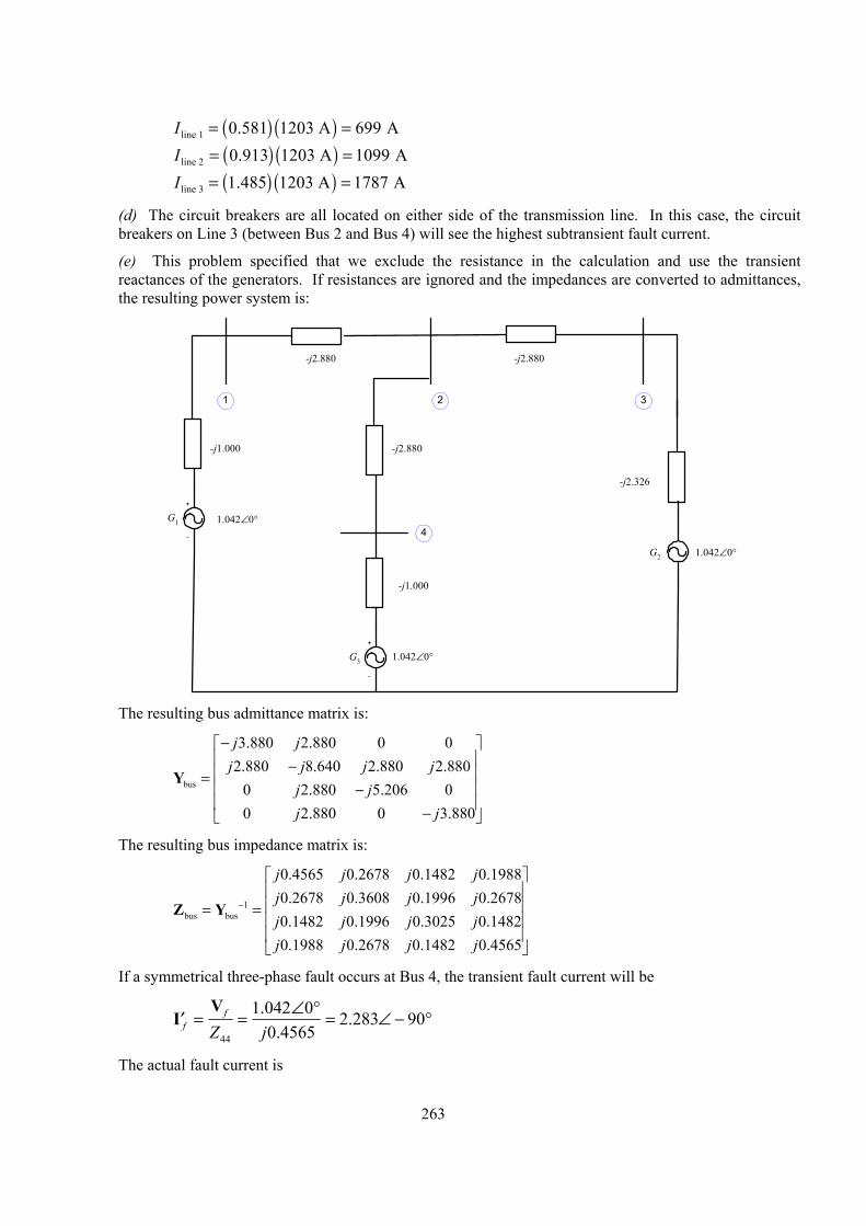
263
( ) ( )line 1 0.581 1203 A 699 AI = =
( ) ( )line 2 0.913 1203 A 1099 AI = =
( ) ( )line 3 1.485 1203 A 1787 AI = =
(d) The circuit breakers are all located on either side of the transmission line. In this case, the circuit breakers on Line 3 (between Bus 2 and Bus 4) will see the highest subtransient fault current.
(e) This problem specified that we exclude the resistance in the calculation and use the transient reactances of the generators. If resistances are ignored and the impedances are converted to admittances, the resulting power system is:
+
-
G3
-j1.000
1.042∠0°
1.042∠0°
1
4
32
+
-
G1
G2 1.042∠0°
-j2.880
-j2.880
-j1.000
-j2.326
-j2.880
The resulting bus admittance matrix is:
bus
3.880 2.880 0 02.880 8.640 2.880 2.880
0 2.880 5.206 00 2.880 0 3.880
j jj j j j
j jj j
− − = − −
Y
The resulting bus impedance matrix is:
1bus bus
0.4565 0.2678 0.1482 0.19880.2678 0.3608 0.1996 0.26780.1482 0.1996 0.3025 0.14820.1988 0.2678 0.1482 0.4565
j j j jj j j jj j j jj j j j
−
= =
Z Y
If a symmetrical three-phase fault occurs at Bus 4, the transient fault current will be
44
1.042 0 2.283 900.4565
ff Z j
∠ °= = = ∠ − °′V
I
The actual fault current is
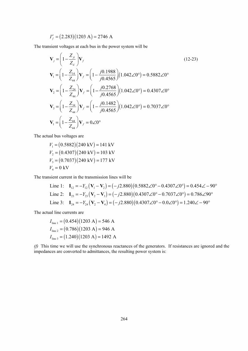
264
( ) ( )2.283 1203 A 2746 AfI = =′
The transient voltages at each bus in the power system will be
1 jij f
ii
ZZ
= −
V V (12-23)
( )141
44
0.19881 1 1.042 0 0.5882 00.4565f
Z jZ j
= − = − ∠ ° = ∠ °
V V
( )242
44
0.27681 1 1.042 0 0.4307 00.4565f
Z jZ j
= − = − ∠ ° = ∠ °
V V
( )343
44
0.14821 1 1.042 0 0.7037 00.4565f
Z jZ j
= − = − ∠ ° = ∠ °
V V
441
44
1 0 0fZZ
= − = ∠ °
V V
The actual bus voltages are
( ) ( )1 0.5882 240 kV 141 kVV = =
( ) ( )2 0.4307 240 kV 103 kVV = =
( ) ( )3 0.7037 240 kV 177 kVV = = 4 0 kVV =
The transient current in the transmission lines will be
( ) ( ) ( )12 12 1 2Line 1: 2.880 0.5882 0 0.4307 0 0.454 90Y j= − − = − ∠ ° − ∠ ° = ∠ − °I V V
( ) ( ) ( )23 23 2 3Line 2: 2.880 0.4307 0 0.7037 0 0.786 90Y j= − − = − ∠ ° − ∠ ° = ∠ °I V V
( ) ( ) ( )24 24 2 4Line 3: 2.880 0.4307 0 0.0 0 1.240 90Y j= − − = − ∠ ° − ∠ ° = ∠ − °I V V
The actual line currents are
( ) ( )line 1 0.454 1203 A 546 AI = =
( ) ( )line 2 0.786 1203 A 946 AI = =
( ) ( )line 3 1.240 1203 A 1492 AI = =
(f) This time we will use the synchronous reactances of the generators. If resistances are ignored and the impedances are converted to admittances, the resulting power system is:
265
+
-
G3
-j0.455
1.042∠0°
1.042∠0°
1
4
32
+
-
G1
G2 1.042∠0°
-j2.880
-j2.880
-j0.455
-j0.781
-j2.880
The resulting bus admittance matrix is:
bus
3.335 2.880 0 02.880 8.640 2.880 2.880
0 2.880 3.661 00 2.880 0 3.335
j jj j j j
j jj j
− − = − −
Y
The resulting bus impedance matrix is:
1bus bus
0.8324 0.6167 0.4852 0.53260.6167 0.7142 0.5618 0.61670.4852 0.5618 0.7151 0.48520.5326 0.6167 0.4852 0.8324
j j j jj j j jj j j jj j j j
−
= =
Z Y
If a symmetrical three-phase fault occurs at Bus 4, the steady-state fault current will be
44
1.042 0 1.2518 900.8324
ff Z j
∠ °= = = ∠ − °V
I
The actual fault current is
( ) ( )1.2518 1203 A 1506 AfI = =
The steady-state voltages at each bus in the power system will be
1 jij f
ii
ZZ
= −
V V (12-23)
( )141
44
0.53261 1 1.042 0 0.3753 00.8324f
Z jZ j
= − = − ∠ ° = ∠ °
V V
266
( )242
44
0.61671 1 1.042 0 0.2700 00.8324f
Z jZ j
= − = − ∠ ° = ∠ °
V V
( )343
44
0.48521 1 1.042 0 0.4346 00.8324f
Z jZ j
= − = − ∠ ° = ∠ °
V V
441
44
1 0 0fZZ
= − = ∠ °
V V
The actual bus voltages are
( ) ( )1 0.3753 240 kV 90 kVV = =
( ) ( )2 0.2700 240 kV 65 kVV = =
( ) ( )3 0.4346 240 kV 104 kVV = = 4 0 kVV =
The steady-state current in the transmission lines will be
( ) ( ) ( )12 12 1 2Line 1: 2.880 0.3753 0 0.2700 0 0.303 90Y j= − − = − ∠ ° − ∠ ° = ∠ − °I V V
( ) ( ) ( )23 23 2 3Line 2: 2.880 0.2700 0 0.4346 0 0.474 90Y j= − − = − ∠ ° − ∠ ° = ∠ °I V V
( ) ( ) ( )24 24 2 4Line 3: 2.880 0.2700 0 0.0 0 0.778 90Y j= − − = − ∠ ° − ∠ ° = ∠ − °I V V
The actual line currents are
( ) ( )line 1 0.303 1203 A 365 AI = =
( ) ( )line 2 0.474 1203 A 570 AI = =
( ) ( )line 3 0.778 1203 A 936 AI = =
(g) The per-unit short-circuit MVA at Bus 4 is just equal to the per-unit fault current at that bus.
pu ,puShort-circuit MVA 2.283SCI= =
Therefore, the subtransient short-circuit MVA at Bus 4 is
( ) ( )pu baseShort-circuit MVA Short-circuit MVA S=
( ) ( )Short-circuit MVA 2.283 500 MVA 1142 MVA= =
Note: This problem could also be solved using program faults, it we treat the terminals of each generator as an additional bus. The input file for this power system is shown below.
% File describing the power system of Problem 12-2.%% System data has the form:%SYSTEM name baseMVASYSTEM Prob12_2 500%% Bus data has the form:%BUS name voltsBUS One 1.042BUS Two 1.042BUS Three 1.042
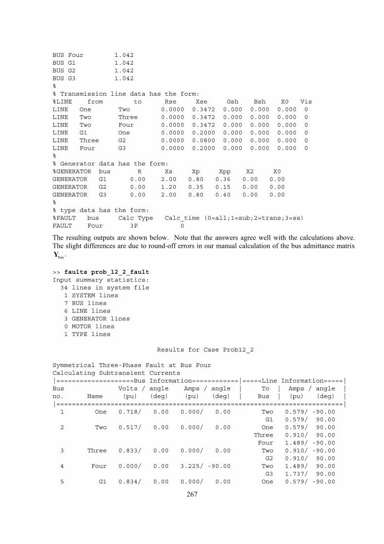
267
BUS Four 1.042BUS G1 1.042BUS G2 1.042BUS G3 1.042%% Transmission line data has the form:%LINE from to Rse Xse Gsh Bsh X0 VisLINE One Two 0.0000 0.3472 0.000 0.000 0.000 0LINE Two Three 0.0000 0.3472 0.000 0.000 0.000 0LINE Two Four 0.0000 0.3472 0.000 0.000 0.000 0LINE G1 One 0.0000 0.2000 0.000 0.000 0.000 0LINE Three G2 0.0000 0.0800 0.000 0.000 0.000 0LINE Four G3 0.0000 0.2000 0.000 0.000 0.000 0%% Generator data has the form:%GENERATOR bus R Xs Xp Xpp X2 X0GENERATOR G1 0.00 2.00 0.80 0.36 0.00 0.00GENERATOR G2 0.00 1.20 0.35 0.15 0.00 0.00GENERATOR G3 0.00 2.00 0.80 0.40 0.00 0.00%% type data has the form:%FAULT bus Calc Type Calc_time (0=all;1=sub;2=trans;3=ss)FAULT Four 3P 0
The resulting outputs are shown below. Note that the answers agree well with the calculations above. The slight differences are due to round-off errors in our manual calculation of the bus admittance matrix
busY .
>> faults prob_12_2_faultInput summary statistics:34 lines in system file1 SYSTEM lines7 BUS lines6 LINE lines3 GENERATOR lines0 MOTOR lines1 TYPE lines
Results for Case Prob12_2
Symmetrical Three-Phase Fault at Bus FourCalculating Subtransient Currents|====================Bus Information============|=====Line Information=====|Bus Volts / angle Amps / angle | To | Amps / angle |no. Name (pu) (deg) (pu) (deg) | Bus | (pu) (deg) ||==========================================================================|1 One 0.718/ 0.00 0.000/ 0.00 Two 0.579/ -90.00
G1 0.579/ 90.002 Two 0.517/ 0.00 0.000/ 0.00 One 0.579/ 90.00
Three 0.910/ 90.00Four 1.489/ -90.00
3 Three 0.833/ 0.00 0.000/ 0.00 Two 0.910/ -90.00G2 0.910/ 90.00
4 Four 0.000/ 0.00 3.225/ -90.00 Two 1.489/ 90.00G3 1.737/ 90.00
5 G1 0.834/ 0.00 0.000/ 0.00 One 0.579/ -90.00
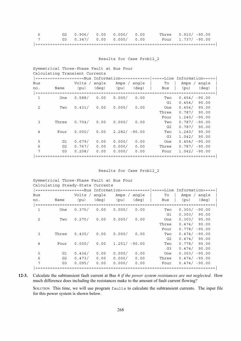
268
6 G2 0.906/ 0.00 0.000/ 0.00 Three 0.910/ -90.007 G3 0.347/ 0.00 0.000/ 0.00 Four 1.737/ -90.00
|==========================================================================|
Results for Case Prob12_2
Symmetrical Three-Phase Fault at Bus FourCalculating Transient Currents|====================Bus Information============|=====Line Information=====|Bus Volts / angle Amps / angle | To | Amps / angle |no. Name (pu) (deg) (pu) (deg) | Bus | (pu) (deg) ||==========================================================================|1 One 0.588/ 0.00 0.000/ 0.00 Two 0.454/ -90.00
G1 0.454/ 90.002 Two 0.431/ 0.00 0.000/ 0.00 One 0.454/ 90.00
Three 0.787/ 90.00Four 1.240/ -90.00
3 Three 0.704/ 0.00 0.000/ 0.00 Two 0.787/ -90.00G2 0.787/ 90.00
4 Four 0.000/ 0.00 2.282/ -90.00 Two 1.240/ 90.00G3 1.042/ 90.00
5 G1 0.679/ 0.00 0.000/ 0.00 One 0.454/ -90.006 G2 0.767/ 0.00 0.000/ 0.00 Three 0.787/ -90.007 G3 0.208/ 0.00 0.000/ 0.00 Four 1.042/ -90.00
|==========================================================================|
Results for Case Prob12_2
Symmetrical Three-Phase Fault at Bus FourCalculating Steady-State Currents|====================Bus Information============|=====Line Information=====|Bus Volts / angle Amps / angle | To | Amps / angle |no. Name (pu) (deg) (pu) (deg) | Bus | (pu) (deg) ||==========================================================================|1 One 0.375/ 0.00 0.000/ 0.00 Two 0.303/ -90.00
G1 0.303/ 90.002 Two 0.270/ 0.00 0.000/ 0.00 One 0.303/ 90.00
Three 0.474/ 90.00Four 0.778/ -90.00
3 Three 0.435/ 0.00 0.000/ 0.00 Two 0.474/ -90.00G2 0.474/ 90.00
4 Four 0.000/ 0.00 1.251/ -90.00 Two 0.778/ 90.00G3 0.474/ 90.00
5 G1 0.436/ 0.00 0.000/ 0.00 One 0.303/ -90.006 G2 0.473/ 0.00 0.000/ 0.00 Three 0.474/ -90.007 G3 0.095/ 0.00 0.000/ 0.00 Four 0.474/ -90.00
|==========================================================================|
12-3. Calculate the subtransient fault current at Bus 4 if the power system resistances are not neglected. How much difference does including the resistances make to the amount of fault current flowing?
SOLUTION This time, we will use program faults to calculate the subtransient currents. The input file for this power system is shown below.
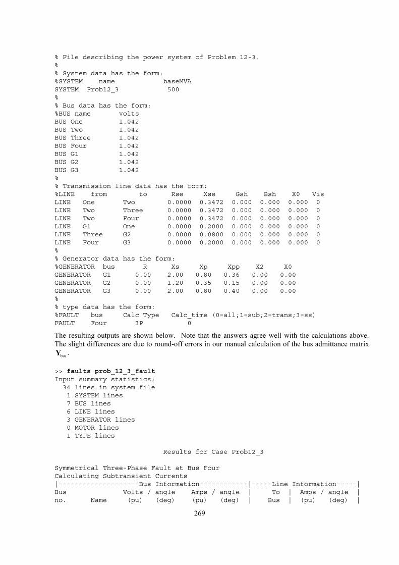
269
% File describing the power system of Problem 12-3.%% System data has the form:%SYSTEM name baseMVASYSTEM Prob12_3 500%% Bus data has the form:%BUS name voltsBUS One 1.042BUS Two 1.042BUS Three 1.042BUS Four 1.042BUS G1 1.042BUS G2 1.042BUS G3 1.042%% Transmission line data has the form:%LINE from to Rse Xse Gsh Bsh X0 VisLINE One Two 0.0000 0.3472 0.000 0.000 0.000 0LINE Two Three 0.0000 0.3472 0.000 0.000 0.000 0LINE Two Four 0.0000 0.3472 0.000 0.000 0.000 0LINE G1 One 0.0000 0.2000 0.000 0.000 0.000 0LINE Three G2 0.0000 0.0800 0.000 0.000 0.000 0LINE Four G3 0.0000 0.2000 0.000 0.000 0.000 0%% Generator data has the form:%GENERATOR bus R Xs Xp Xpp X2 X0GENERATOR G1 0.00 2.00 0.80 0.36 0.00 0.00GENERATOR G2 0.00 1.20 0.35 0.15 0.00 0.00GENERATOR G3 0.00 2.00 0.80 0.40 0.00 0.00%% type data has the form:%FAULT bus Calc Type Calc_time (0=all;1=sub;2=trans;3=ss)FAULT Four 3P 0
The resulting outputs are shown below. Note that the answers agree well with the calculations above. The slight differences are due to round-off errors in our manual calculation of the bus admittance matrix
busY .
>> faults prob_12_3_faultInput summary statistics:34 lines in system file1 SYSTEM lines7 BUS lines6 LINE lines3 GENERATOR lines0 MOTOR lines1 TYPE lines
Results for Case Prob12_3
Symmetrical Three-Phase Fault at Bus FourCalculating Subtransient Currents|====================Bus Information============|=====Line Information=====|Bus Volts / angle Amps / angle | To | Amps / angle |no. Name (pu) (deg) (pu) (deg) | Bus | (pu) (deg) |
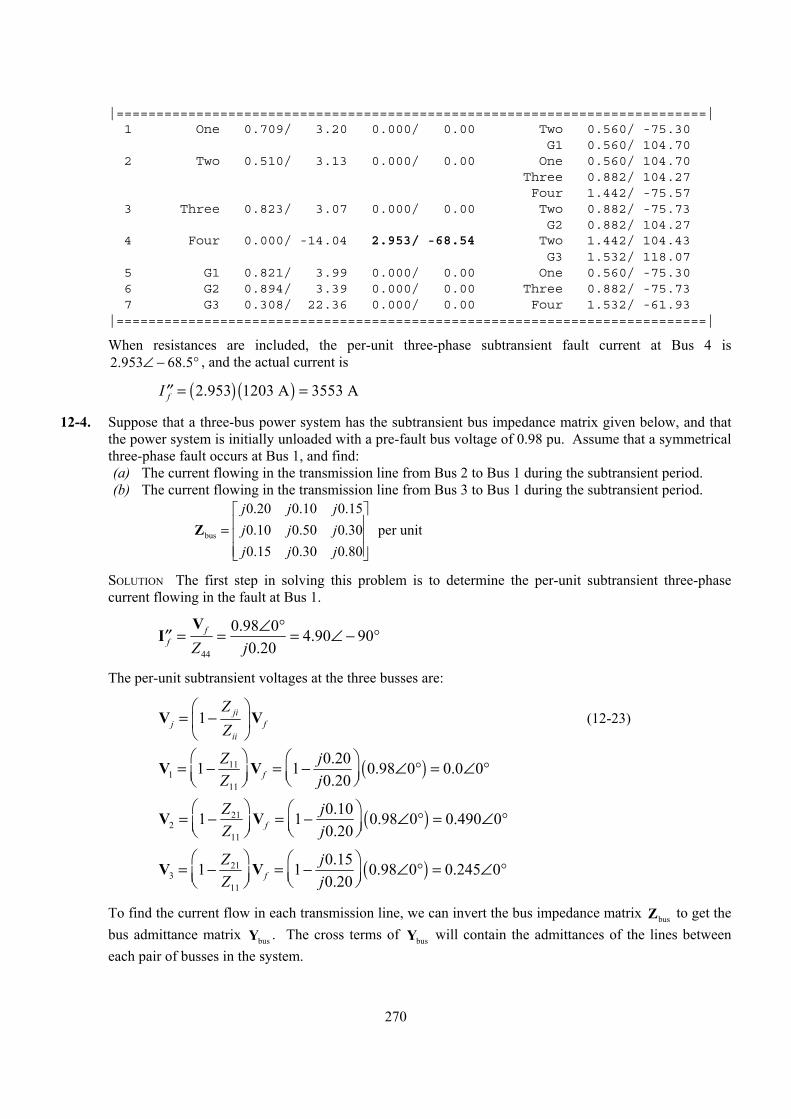
270
|==========================================================================|1 One 0.709/ 3.20 0.000/ 0.00 Two 0.560/ -75.30
G1 0.560/ 104.702 Two 0.510/ 3.13 0.000/ 0.00 One 0.560/ 104.70
Three 0.882/ 104.27Four 1.442/ -75.57
3 Three 0.823/ 3.07 0.000/ 0.00 Two 0.882/ -75.73G2 0.882/ 104.27
4 Four 0.000/ -14.04 2.953/ -68.54 Two 1.442/ 104.43G3 1.532/ 118.07
5 G1 0.821/ 3.99 0.000/ 0.00 One 0.560/ -75.306 G2 0.894/ 3.39 0.000/ 0.00 Three 0.882/ -75.737 G3 0.308/ 22.36 0.000/ 0.00 Four 1.532/ -61.93
|==========================================================================|
When resistances are included, the per-unit three-phase subtransient fault current at Bus 4 is 2.953 68.5∠ − ° , and the actual current is
( ) ( )2.953 1203 A 3553 AfI = =′′
12-4. Suppose that a three-bus power system has the subtransient bus impedance matrix given below, and that the power system is initially unloaded with a pre-fault bus voltage of 0.98 pu. Assume that a symmetrical three-phase fault occurs at Bus 1, and find: (a) The current flowing in the transmission line from Bus 2 to Bus 1 during the subtransient period. (b) The current flowing in the transmission line from Bus 3 to Bus 1 during the subtransient period.
bus
0.20 0.10 0.150.10 0.50 0.30 per unit0.15 0.30 0.80
j j jj j jj j j
=
Z
SOLUTION The first step in solving this problem is to determine the per-unit subtransient three-phase current flowing in the fault at Bus 1.
44
0.98 0 4.90 900.20
ff Z j
∠ °= = = ∠ − °′′V
I
The per-unit subtransient voltages at the three busses are:
1 jij f
ii
ZZ
= −
V V (12-23)
( )111
11
0.201 1 0.98 0 0.0 00.20f
Z jZ j
= − = − ∠ ° = ∠ °
V V
( )212
11
0.101 1 0.98 0 0.490 00.20f
Z jZ j
= − = − ∠ ° = ∠ °
V V
( )213
11
0.151 1 0.98 0 0.245 00.20f
Z jZ j
= − = − ∠ ° = ∠ °
V V
To find the current flow in each transmission line, we can invert the bus impedance matrix busZ to get the bus admittance matrix busY . The cross terms of busY will contain the admittances of the lines between each pair of busses in the system.
271
1bus bus
5.9903 0.6763 0.86960.6763 2.6570 0.8696 per unit0.8696 0.8696 1.7391
j j jj j jj j j
−
− = = − −
Y Z
( ) ( ) ( )21 21 2 1 0.6763 0.490 0 0.0 0 0.3314 90Y j= − − = − ∠ ° − ∠ ° = ∠ − °I V V
( ) ( ) ( )31 31 3 1 0.8696 0.245 0 0.0 0 0.2131 90Y j= − − = − ∠ ° − ∠ ° = ∠ − °I V V
12-5. A 500 kVA, 480 V, 60 Hz, Y-connected synchronous generator has a subtransient reactance X ′′ of 0.10 pu, a transient reactance X ′ of 0.22 pu, and a synchronous reactance SX of 1.0 pu. Suppose that this machine is supplying rated load at rated voltage and 0.9 PF lagging. (a) What is the magnitude of the internal generated voltage AE of this machine? (b) A fault occurs at the terminals of the generator. What is the magnitude of the voltage behind
subtransient reactance AE′′ of this machine? (c) What is the subtransient current fI ′′ flowing from this generator?
(d) What is the magnitude of the voltage behind transient reactance AE′ of this machine? (e) What is the transient current fI ′ flowing from this generator during the transient period? (f) Suppose that we ignore the loads on the generator and assume that it was unloaded before the fault
occurred. What is the subtransient current fI ′′ flowing from this generator? How much error is caused by ignoring the initial loading of the generator?
SOLUTION Since this machine is Y-connected, its phase voltage is ( )480 V / 3 277 V= .
Base values of this generator are
base 500 kVAS = LL,base 480 VV =
,base 277 VVφ =
( )
basebase
,base
500,000 VA 602 A3 3 480 VSIVφ
= = =
( ) ( )2
LL,basebase
3 ,base
480 V0.4608
500,000 VAV
ZS φ
= = = Ω
(a) The power factor is 0.9 lagging, so the impedance angle ( )1cos 0.9 25.84θ −= = ° . Therefore, the per-unit phasor current is
1.0 25.84A = ∠ − °I
The internal generated voltage AE of this machine is given by
( ) ( )1 0 1.0 1 25.84 1.695 32.1 puA S AjX jφ= + = ∠ ° + ∠ − ° = ∠ °E V I
or ( ) ( )1.695 32.1 277 V 469.5 32.1 VA = ∠ ° = ∠ °E
Therefore, the magnitude AE is 469.5 V.
(b) The voltage behind subtransient reactance AE′′ is given by
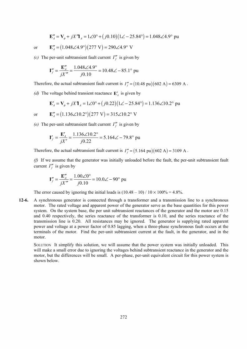
272
( ) ( )1 0 0.10 1 25.84 1.048 4.9 puA AjX jφ= + = ∠ ° + ∠ − ° = ∠ °′′ ′′E V I
or ( ) ( )1.048 4.9 277 V 290 4.9 VA = ∠ ° = ∠ °′′E
(c) The per-unit subtransient fault current fI ′′ is given by
1.048 4.9 10.48 85.1 pu
0.10A
f jX j∠ °′′= = = ∠ − °′′
′′EI
Therefore, the actual subtransient fault current is ( ) ( )10.48 pu 602 A 6309 AfI = =′′ .
(d) The voltage behind transient reactance A′E is given by
( ) ( )1 0 0.22 1 25.84 1.136 10.2 puA AjX jφ= + = ∠ ° + ∠ − ° = ∠ °′ ′E V I
or ( ) ( )1.136 10.2 277 V 315 10.2 VA = ∠ ° = ∠ °′′E
(e) The per-unit subtransient fault current fI ′′ is given by
1.136 10.2 5.164 79.8 pu
0.22A
f jX j∠ °′= = = ∠ − °′
′EI
Therefore, the actual subtransient fault current is ( ) ( )5.164 pu 602 A 3109 AfI = =′′ .
(f) If we assume that the generator was initially unloaded before the fault, the per-unit subtransient fault current fI ′′ is given by
1.00 0 10.0 90 pu
0.10A
f jX j∠ °′′= = = ∠ − °′′
′′EI
The error caused by ignoring the initial loads is (10.48 – 10) / 10 × 100% = 4.8%.
12-6. A synchronous generator is connected through a transformer and a transmission line to a synchronous motor. The rated voltage and apparent power of the generator serve as the base quantities for this power system. On the system base, the per unit subtransient reactances of the generator and the motor are 0.15 and 0.40 respectively, the series reactance of the transformer is 0.10, and the series reactance of the transmission line is 0.20. All resistances may be ignored. The generator is supplying rated apparent power and voltage at a power factor of 0.85 lagging, when a three-phase synchronous fault occurs at the terminals of the motor. Find the per-unit subtransient current at the fault, in the generator, and in the motor.
SOLUTION It simplify this solution, we will assume that the power system was initially unloaded. This will make a small error due to ignoring the voltages behind subtransient reactance in the generator and the motor, but the differences will be small. A per-phase, per-unit equivalent circuit for this power system is shown below.
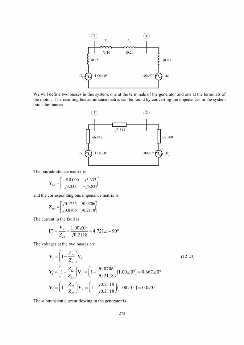
273
+
-
G1
L1T1
M2
j0.20j0.10
j0.40
1.00∠0° 1.00∠0°
1 2
j0.15
+
-
We will define two busses in this system, one at the terminals of the generator and one at the terminals of
the motor. The resulting bus admittance matrix can be found by converting the impedances in the system into admittances.
+
-
G1 M2
-j3.333
-j2.500
1.00∠0° 1.00∠0°
1 2
-j6.667
+
-
The bus admittance matrix is
bus
10.000 3.3333.333 5.833j jj j
− = −
Y
and the corresponding bus impedance matrix is
bus
0.1235 0.07060.0706 0.2118
j jj j
=
Z
The current in the fault is
22
1.00 0 4.721 900.2118
ff Z j
∠ °= = = ∠ − °′′V
I
The voltages at the two busses are
1 jij f
ii
ZZ
= −
V V (12-23)
( )121
22
0.07061 1 1.00 0 0.667 00.2118f
Z jZ j
= − = − ∠ ° = ∠ °
V V
( )222
22
0.21181 1 1.00 0 0.0 00.2118f
Z jZ j
= − = − ∠ ° = ∠ °
V V
The subtransient current flowing in the generator is
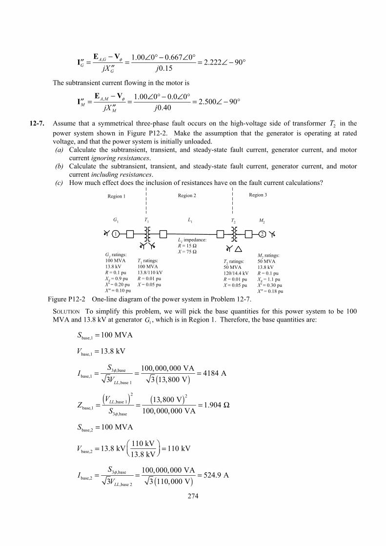
274
, 1.00 0 0.667 0 2.222 900.15
A GG
GjX jφ− ∠ ° − ∠ °= = = ∠ − °′′
′′E V
I
The subtransient current flowing in the motor is
, 1.00 0 0.0 0 2.500 900.40
A MM
MjX jφ− ∠ ° − ∠ °= = = ∠ − °′′
′′E V
I
12-7. Assume that a symmetrical three-phase fault occurs on the high-voltage side of transformer 2T in the power system shown in Figure P12-2. Make the assumption that the generator is operating at rated voltage, and that the power system is initially unloaded. (a) Calculate the subtransient, transient, and steady-state fault current, generator current, and motor
current ignoring resistances. (b) Calculate the subtransient, transient, and steady-state fault current, generator current, and motor
current including resistances. (c) How much effect does the inclusion of resistances have on the fault current calculations?
1 2
G1 ratings:100 MVA13.8 kVR = 0.1 puXS = 0.9 puX' = 0.20 puX" = 0.10 pu
T1 ratings:100 MVA13.8/110 kVR = 0.01 puX = 0.05 pu
G1 T1 T2 M2
T2 ratings:50 MVA120/14.4 kVR = 0.01 puX = 0.05 pu
M2 ratings:50 MVA13.8 kVR = 0.1 puXS = 1.1 puX' = 0.30 puX" = 0.18 pu
L1 impedance:R = 15 ΩX = 75 Ω
L1
Region 1 Region 2 Region 3
Figure P12-2 One-line diagram of the power system in Problem 12-7.
SOLUTION To simplify this problem, we will pick the base quantities for this power system to be 100 MVA and 13.8 kV at generator 1G , which is in Region 1. Therefore, the base quantities are:
base,1 100 MVAS =
base,1 13.8 kVV =
( )
3 ,basebase,1
,base 1
100,000,000 VA 4184 A3 3 13,800 VLL
SI
Vφ= = =
( ) ( )
2 2,base 1
base,13 ,base
13,800 V1.904
100,000,000 VALLV
ZS φ
= = = Ω
base,2 100 MVAS =
base,2110 kV13.8 kV 110 kV13.8 kV
V = =
( )
3 ,basebase,2
,base 2
100,000,000 VA 524.9 A3 3 110,000 VLL
SI
Vφ= = =
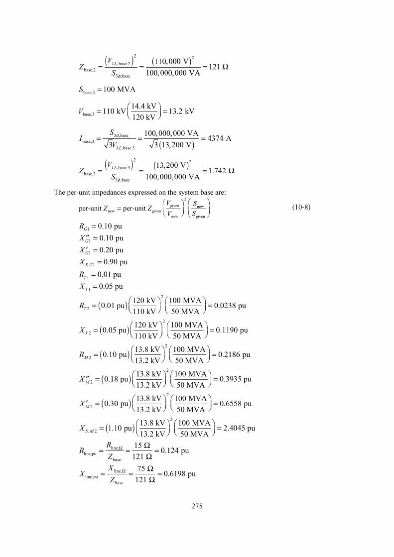
275
( ) ( )
2 2,base 2
base,23 ,base
110,000 V121
100,000,000 VALLV
ZS φ
= = = Ω
base,3 100 MVAS =
base,314.4 kV110 kV 13.2 kV120 kV
V = =
( )
3 ,basebase,3
,base 3
100,000,000 VA 4374 A3 3 13,200 VLL
SI
Vφ= = =
( ) ( )
2 2,base 3
base,33 ,base
13,200 V1.742
100,000,000 VALLV
ZS φ
= = = Ω
The per-unit impedances expressed on the system base are:
2
given newnew given
new given
per-unit per-unit V SZ ZV S
=
(10-8)
1 0.10 puGR = 1 0.10 puGX =′′ 1 0.20 puGX =′ , 1 0.90 puS GX =
1 0.01 puTR = 1 0.05 puTX =
( )2
2120 kV 100 MVA0.01 pu 0.0238 pu110 kV 50 MVATR = =
( )2
2120 kV 100 MVA0.05 pu 0.1190 pu110 kV 50 MVATX = =
( )2
213.8 kV 100 MVA0.10 pu 0.2186 pu13.2 kV 50 MVAMR = =
( )2
213.8 kV 100 MVA0.18 pu 0.3935 pu13.2 kV 50 MVAMX = =′′
( )2
213.8 kV 100 MVA0.30 pu 0.6558 pu13.2 kV 50 MVAMX = =′
( )2
, 213.8 kV 100 MVA1.10 pu 2.4045 pu13.2 kV 50 MVAS MX = =
line,line,pu
base
15 0.124 pu121
RR
ZΩ Ω= = =
Ω
line,line,pu
base
75 0.6198 pu121
XX
ZΩ Ω= = =
Ω
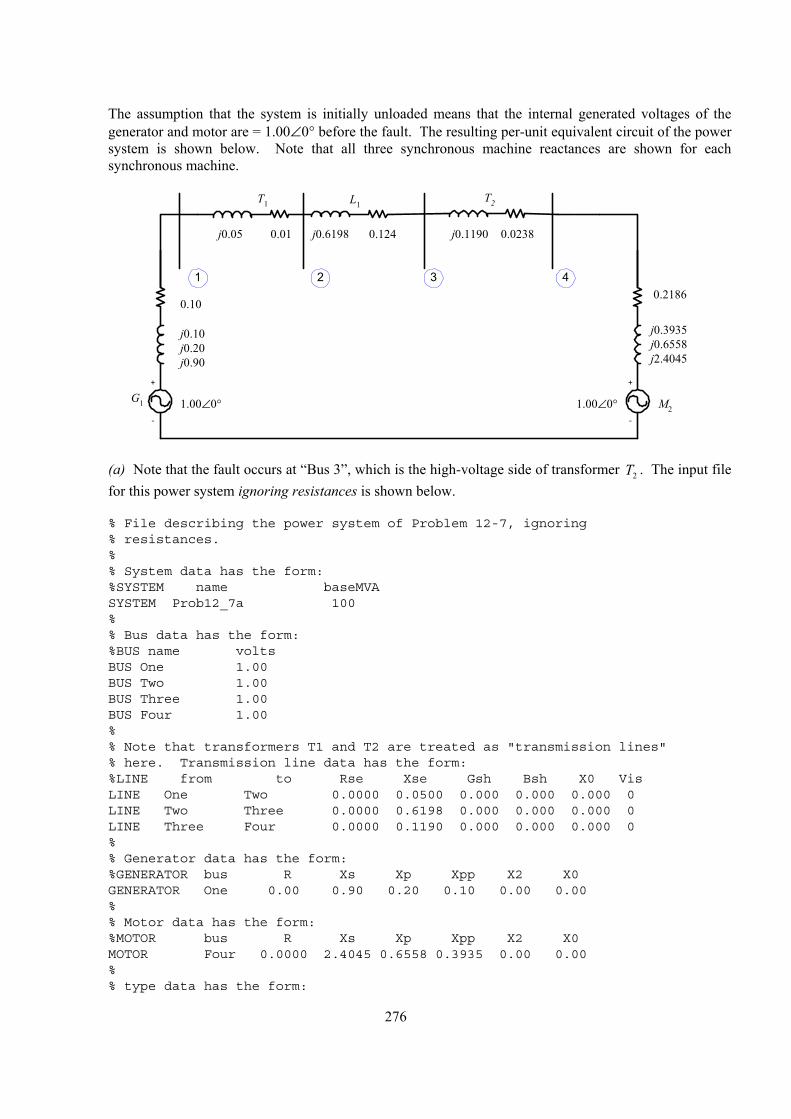
276
The assumption that the system is initially unloaded means that the internal generated voltages of the generator and motor are = 1.00∠0° before the fault. The resulting per-unit equivalent circuit of the power system is shown below. Note that all three synchronous machine reactances are shown for each synchronous machine.
+
-
G1
0.10
j0.10j0.20j0.90
L1T1
j0.1190
+
-
M2
0.2186
j0.3935j0.6558j2.4045
T2
j0.6198 0.02380.1240.01j0.05
1.00∠0° 1.00∠0°
1 32 4
(a) Note that the fault occurs at “Bus 3”, which is the high-voltage side of transformer 2T . The input file
for this power system ignoring resistances is shown below.
% File describing the power system of Problem 12-7, ignoring% resistances.%% System data has the form:%SYSTEM name baseMVASYSTEM Prob12_7a 100%% Bus data has the form:%BUS name voltsBUS One 1.00BUS Two 1.00BUS Three 1.00BUS Four 1.00%% Note that transformers T1 and T2 are treated as "transmission lines"% here. Transmission line data has the form:%LINE from to Rse Xse Gsh Bsh X0 VisLINE One Two 0.0000 0.0500 0.000 0.000 0.000 0LINE Two Three 0.0000 0.6198 0.000 0.000 0.000 0LINE Three Four 0.0000 0.1190 0.000 0.000 0.000 0%% Generator data has the form:%GENERATOR bus R Xs Xp Xpp X2 X0GENERATOR One 0.00 0.90 0.20 0.10 0.00 0.00%% Motor data has the form:%MOTOR bus R Xs Xp Xpp X2 X0MOTOR Four 0.0000 2.4045 0.6558 0.3935 0.00 0.00%% type data has the form:
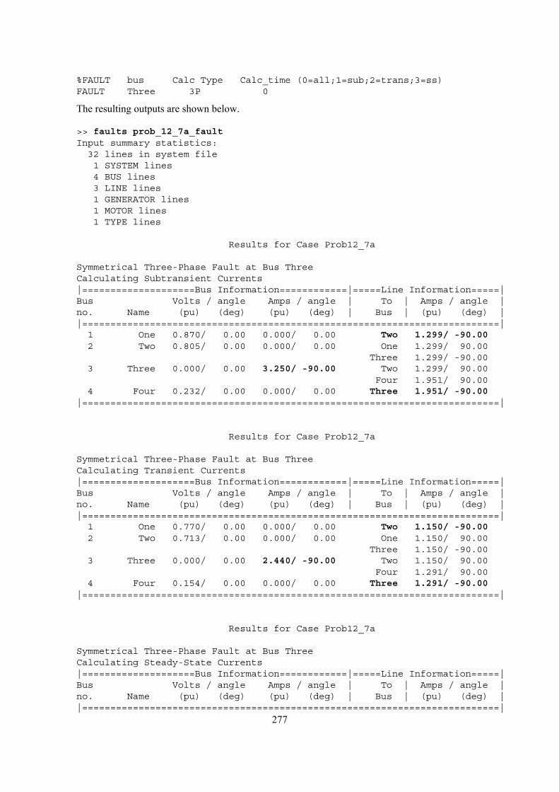
277
%FAULT bus Calc Type Calc_time (0=all;1=sub;2=trans;3=ss)FAULT Three 3P 0
The resulting outputs are shown below.
>> faults prob_12_7a_faultInput summary statistics:32 lines in system file1 SYSTEM lines4 BUS lines3 LINE lines1 GENERATOR lines1 MOTOR lines1 TYPE lines
Results for Case Prob12_7a
Symmetrical Three-Phase Fault at Bus ThreeCalculating Subtransient Currents|====================Bus Information============|=====Line Information=====|Bus Volts / angle Amps / angle | To | Amps / angle |no. Name (pu) (deg) (pu) (deg) | Bus | (pu) (deg) ||==========================================================================|1 One 0.870/ 0.00 0.000/ 0.00 Two 1.299/ -90.002 Two 0.805/ 0.00 0.000/ 0.00 One 1.299/ 90.00
Three 1.299/ -90.003 Three 0.000/ 0.00 3.250/ -90.00 Two 1.299/ 90.00
Four 1.951/ 90.004 Four 0.232/ 0.00 0.000/ 0.00 Three 1.951/ -90.00
|==========================================================================|
Results for Case Prob12_7a
Symmetrical Three-Phase Fault at Bus ThreeCalculating Transient Currents|====================Bus Information============|=====Line Information=====|Bus Volts / angle Amps / angle | To | Amps / angle |no. Name (pu) (deg) (pu) (deg) | Bus | (pu) (deg) ||==========================================================================|1 One 0.770/ 0.00 0.000/ 0.00 Two 1.150/ -90.002 Two 0.713/ 0.00 0.000/ 0.00 One 1.150/ 90.00
Three 1.150/ -90.003 Three 0.000/ 0.00 2.440/ -90.00 Two 1.150/ 90.00
Four 1.291/ 90.004 Four 0.154/ 0.00 0.000/ 0.00 Three 1.291/ -90.00
|==========================================================================|
Results for Case Prob12_7a
Symmetrical Three-Phase Fault at Bus ThreeCalculating Steady-State Currents|====================Bus Information============|=====Line Information=====|Bus Volts / angle Amps / angle | To | Amps / angle |no. Name (pu) (deg) (pu) (deg) | Bus | (pu) (deg) ||==========================================================================|
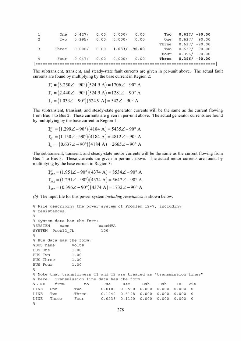
278
1 One 0.427/ 0.00 0.000/ 0.00 Two 0.637/ -90.002 Two 0.395/ 0.00 0.000/ 0.00 One 0.637/ 90.00
Three 0.637/ -90.003 Three 0.000/ 0.00 1.033/ -90.00 Two 0.637/ 90.00
Four 0.396/ 90.004 Four 0.047/ 0.00 0.000/ 0.00 Three 0.396/ -90.00
|==========================================================================|
The subtransient, transient, and steady-state fault currents are given in per-unit above. The actual fault currents are found by multiplying by the base current in Region 2:
( ) ( )3.250 90 524.9 A 1706 90 Af = ∠ − ° = ∠ − °′′I
( ) ( )2.440 90 524.9 A 1281 90 Af = ∠ − ° = ∠ − °′I
( ) ( )1.033 90 524.9 A 542 90 Af = ∠ − ° = ∠ − °I
The subtransient, transient, and steady-state generator currents will be the same as the current flowing from Bus 1 to Bus 2. These currents are given in per-unit above. The actual generator currents are found by multiplying by the base current in Region 1:
( ) ( )1 1.299 90 4184 A 5435 90 AG = ∠ − ° = ∠ − °′′I
( ) ( )1 1.150 90 4184 A 4812 90 AG = ∠ − ° = ∠ − °′I
( ) ( )1 0.637 90 4184 A 2665 90 AG = ∠ − ° = ∠ − °I
The subtransient, transient, and steady-state motor currents will be the same as the current flowing from Bus 4 to Bus 3. These currents are given in per-unit above. The actual motor currents are found by multiplying by the base current in Region 3:
( ) ( )2 1.951 90 4374 A 8534 90 AM = ∠ − ° = ∠ − °′′I
( ) ( )2 1.291 90 4374 A 5647 90 AM = ∠ − ° = ∠ − °′I
( ) ( )2 0.396 90 4374 A 1732 90 AM = ∠ − ° = ∠ − °I
(b) The input file for this power system including resistances is shown below.
% File describing the power system of Problem 12-7, including% resistances.%% System data has the form:%SYSTEM name baseMVASYSTEM Prob12_7b 100%% Bus data has the form:%BUS name voltsBUS One 1.00BUS Two 1.00BUS Three 1.00BUS Four 1.00%% Note that transformers T1 and T2 are treated as "transmission lines"% here. Transmission line data has the form:%LINE from to Rse Xse Gsh Bsh X0 VisLINE One Two 0.0100 0.0500 0.000 0.000 0.000 0LINE Two Three 0.1240 0.6198 0.000 0.000 0.000 0LINE Three Four 0.0238 0.1190 0.000 0.000 0.000 0%
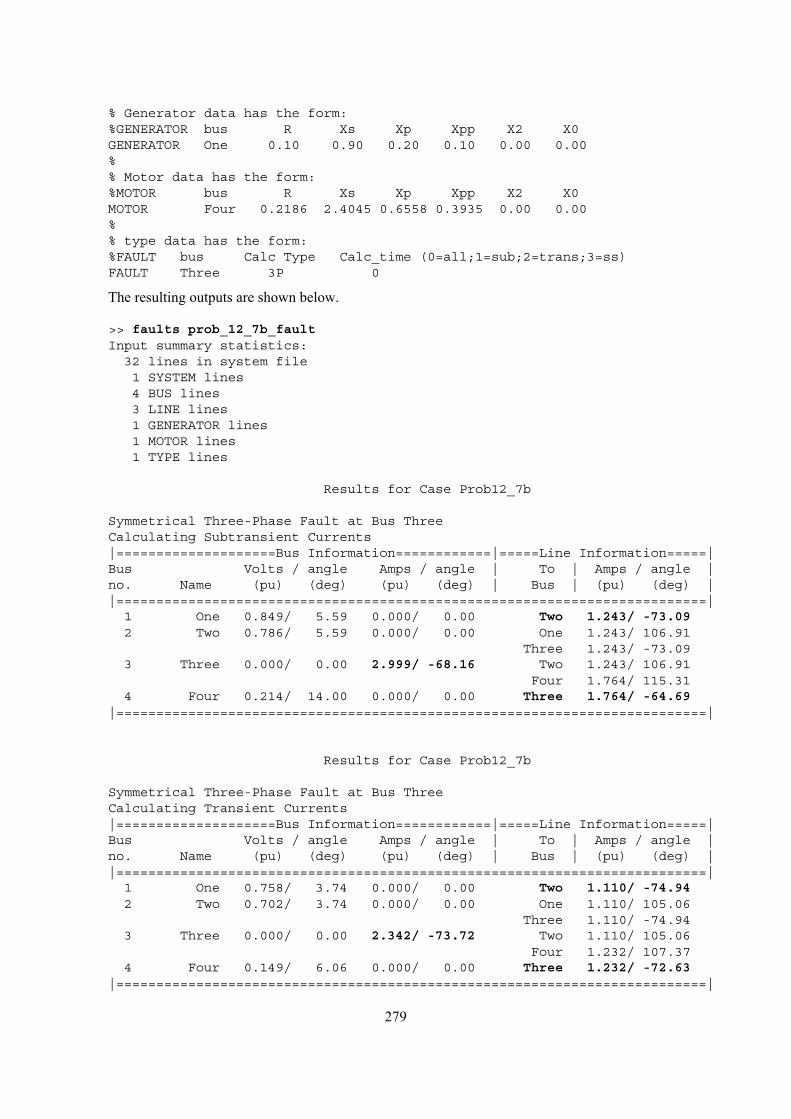
279
% Generator data has the form:%GENERATOR bus R Xs Xp Xpp X2 X0GENERATOR One 0.10 0.90 0.20 0.10 0.00 0.00%% Motor data has the form:%MOTOR bus R Xs Xp Xpp X2 X0MOTOR Four 0.2186 2.4045 0.6558 0.3935 0.00 0.00%% type data has the form:%FAULT bus Calc Type Calc_time (0=all;1=sub;2=trans;3=ss)FAULT Three 3P 0
The resulting outputs are shown below.
>> faults prob_12_7b_faultInput summary statistics:32 lines in system file1 SYSTEM lines4 BUS lines3 LINE lines1 GENERATOR lines1 MOTOR lines1 TYPE lines
Results for Case Prob12_7b
Symmetrical Three-Phase Fault at Bus ThreeCalculating Subtransient Currents|====================Bus Information============|=====Line Information=====|Bus Volts / angle Amps / angle | To | Amps / angle |no. Name (pu) (deg) (pu) (deg) | Bus | (pu) (deg) ||==========================================================================|1 One 0.849/ 5.59 0.000/ 0.00 Two 1.243/ -73.092 Two 0.786/ 5.59 0.000/ 0.00 One 1.243/ 106.91
Three 1.243/ -73.093 Three 0.000/ 0.00 2.999/ -68.16 Two 1.243/ 106.91
Four 1.764/ 115.314 Four 0.214/ 14.00 0.000/ 0.00 Three 1.764/ -64.69
|==========================================================================|
Results for Case Prob12_7b
Symmetrical Three-Phase Fault at Bus ThreeCalculating Transient Currents|====================Bus Information============|=====Line Information=====|Bus Volts / angle Amps / angle | To | Amps / angle |no. Name (pu) (deg) (pu) (deg) | Bus | (pu) (deg) ||==========================================================================|1 One 0.758/ 3.74 0.000/ 0.00 Two 1.110/ -74.942 Two 0.702/ 3.74 0.000/ 0.00 One 1.110/ 105.06
Three 1.110/ -74.943 Three 0.000/ 0.00 2.342/ -73.72 Two 1.110/ 105.06
Four 1.232/ 107.374 Four 0.149/ 6.06 0.000/ 0.00 Three 1.232/ -72.63
|==========================================================================|
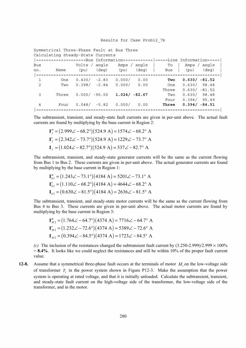
280
Results for Case Prob12_7b
Symmetrical Three-Phase Fault at Bus ThreeCalculating Steady-State Currents|====================Bus Information============|=====Line Information=====|Bus Volts / angle Amps / angle | To | Amps / angle |no. Name (pu) (deg) (pu) (deg) | Bus | (pu) (deg) ||==========================================================================|1 One 0.430/ -2.83 0.000/ 0.00 Two 0.630/ -81.522 Two 0.398/ -2.84 0.000/ 0.00 One 0.630/ 98.48
Three 0.630/ -81.523 Three 0.000/ -90.00 1.024/ -82.67 Two 0.630/ 98.48
Four 0.394/ 95.494 Four 0.048/ -5.82 0.000/ 0.00 Three 0.394/ -84.51
|==========================================================================|
The subtransient, transient, and steady-state fault currents are given in per-unit above. The actual fault currents are found by multiplying by the base current in Region 2:
( ) ( )2.999 68.2 524.9 A 1574 68.2 Af = ∠ − ° = ∠ − °′′I
( ) ( )2.342 73.7 524.9 A 1229 73.7 Af = ∠ − ° = ∠ − °′I
( ) ( )1.024 82.7 524.9 A 537 82.7 Af = ∠ − ° = ∠ − °I
The subtransient, transient, and steady-state generator currents will be the same as the current flowing from Bus 1 to Bus 2. These currents are given in per-unit above. The actual generator currents are found by multiplying by the base current in Region 1:
( ) ( )1 1.243 73.1 4184 A 5201 73.1 AG = ∠ − ° = ∠ − °′′I
( ) ( )1 1.110 68.2 4184 A 4644 68.2 AG = ∠ − ° = ∠ − °′I
( ) ( )1 0.630 81.5 4184 A 2636 81.5 AG = ∠ − ° = ∠ − °I
The subtransient, transient, and steady-state motor currents will be the same as the current flowing from Bus 4 to Bus 3. These currents are given in per-unit above. The actual motor currents are found by multiplying by the base current in Region 3:
( ) ( )2 1.764 64.7 4374 A 7716 64.7 AM = ∠ − ° = ∠ − °′′I
( ) ( )2 1.232 72.6 4374 A 5389 72.6 AM = ∠ − ° = ∠ − °′I
( ) ( )2 0.394 84.5 4374 A 1723 84.5 AM = ∠ − ° = ∠ − °I
(c) The inclusion of the resistances changed the subtransient fault current by (3.250-2.999)/2.999 × 100% = 8.4%. It looks like we could neglect the resistances and still be within 10% of the proper fault current value.
12-8. Assume that a symmetrical three-phase fault occurs at the terminals of motor 1M on the low-voltage side of transformer 1T in the power system shown in Figure P12-3. Make the assumption that the power system is operating at rated voltage, and that it is initially unloaded. Calculate the subtransient, transient, and steady-state fault current on the high-voltage side of the transformer, the low-voltage side of the transformer, and in the motor.
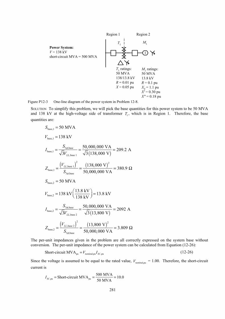
281
1Power System:V = 138 kVshort-circuit MVA = 500 MVA
T1M1
T1 ratings:50 MVA138/13.8 kVR = 0.01 puX = 0.05 pu
M1 ratings:50 MVA13.8 kVR = 0.1 puXS = 1.1 puX' = 0.30 puX" = 0.18 pu
Region 1 Region 2
Figure P12-3 One-line diagram of the power system in Problem 12-8.
SOLUTION To simplify this problem, we will pick the base quantities for this power system to be 50 MVA and 138 kV at the high-voltage side of transformer 1T , which is in Region 1. Therefore, the base quantities are:
base,1 50 MVAS =
base,1 138 kVV =
( )
3 ,basebase,1
,base 1
50,000,000 VA 209.2 A3 3 138,000 VLL
SI
Vφ= = =
( ) ( )
2 2,base 1
base,13 ,base
138,000 V380.9
50,000,000 VALLV
ZS φ
= = = Ω
base,2 50 MVAS =
base,213.8 kV138 kV 13.8 kV138 kV
V = =
( )
3 ,basebase,2
,base 2
50,000,000 VA 2092 A3 3 13,800 VLL
SI
Vφ= = =
( ) ( )
2 2,base 2
base,23 ,base
13,800 V3.809
50,000,000 VALLV
ZS φ
= = = Ω
The per-unit impedances given in the problem are all correctly expressed on the system base without conversion. The per-unit impedance of the power system can be calculated from Equation (12-26):
pu nominal,pu ,puShort-circuit MVA SCV I= (12-26)
Since the voltage is assumed to be equal to the rated value, nominal,puV = 1.00. Therefore, the short-circuit current is
,pu pu500 MVAShort-circuit MVA 10.050 MVASCI = = =
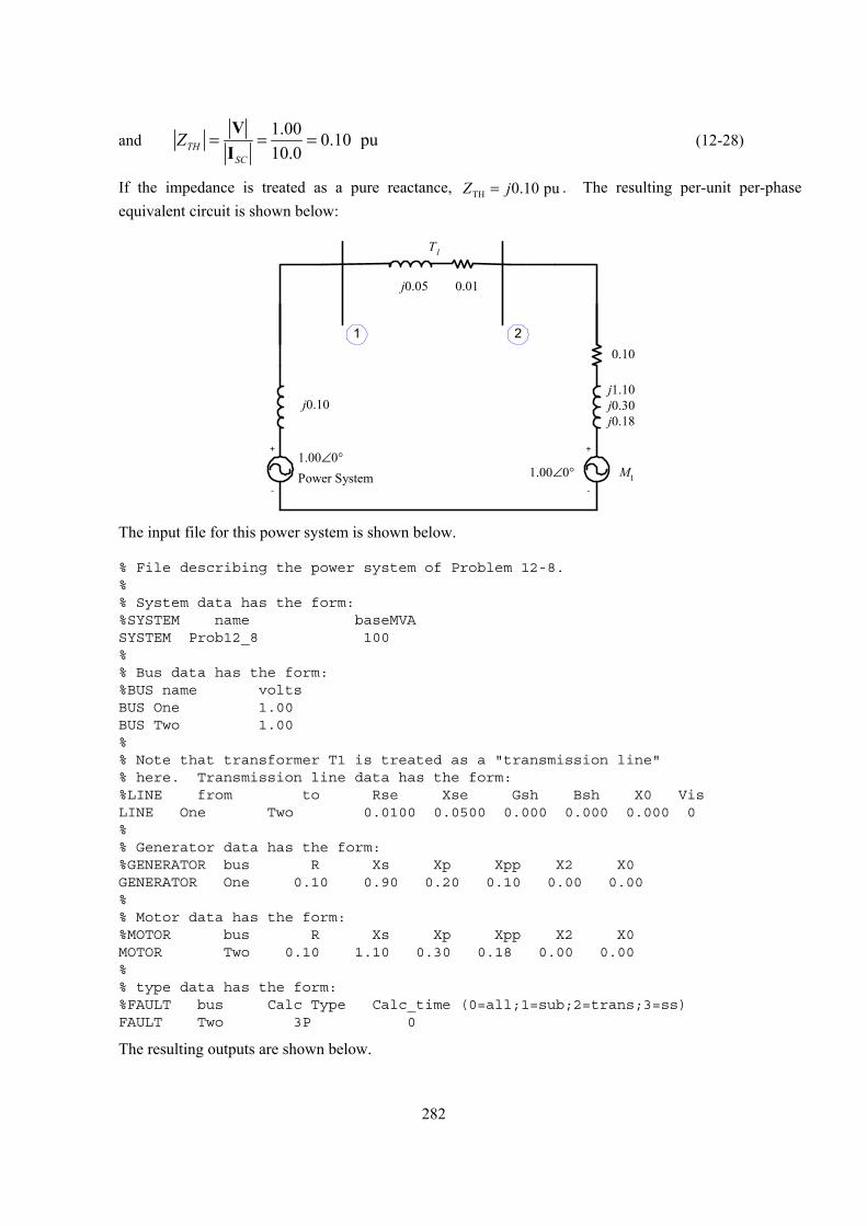
282
and 1.00 0.10 pu10.0TH
SC
Z = = =V
I (12-28)
If the impedance is treated as a pure reactance, TH 0.10 puZ j= . The resulting per-unit per-phase equivalent circuit is shown below:
Power System
j0.10
j0.05
+
-
M1
0.10
j1.10j0.30j0.18
T1
0.01
1.00∠0°1.00∠0°
2
+
-
1
The input file for this power system is shown below.
% File describing the power system of Problem 12-8.%% System data has the form:%SYSTEM name baseMVASYSTEM Prob12_8 100%% Bus data has the form:%BUS name voltsBUS One 1.00BUS Two 1.00%% Note that transformer T1 is treated as a "transmission line"% here. Transmission line data has the form:%LINE from to Rse Xse Gsh Bsh X0 VisLINE One Two 0.0100 0.0500 0.000 0.000 0.000 0%% Generator data has the form:%GENERATOR bus R Xs Xp Xpp X2 X0GENERATOR One 0.10 0.90 0.20 0.10 0.00 0.00%% Motor data has the form:%MOTOR bus R Xs Xp Xpp X2 X0MOTOR Two 0.10 1.10 0.30 0.18 0.00 0.00%% type data has the form:%FAULT bus Calc Type Calc_time (0=all;1=sub;2=trans;3=ss)FAULT Two 3P 0
The resulting outputs are shown below.
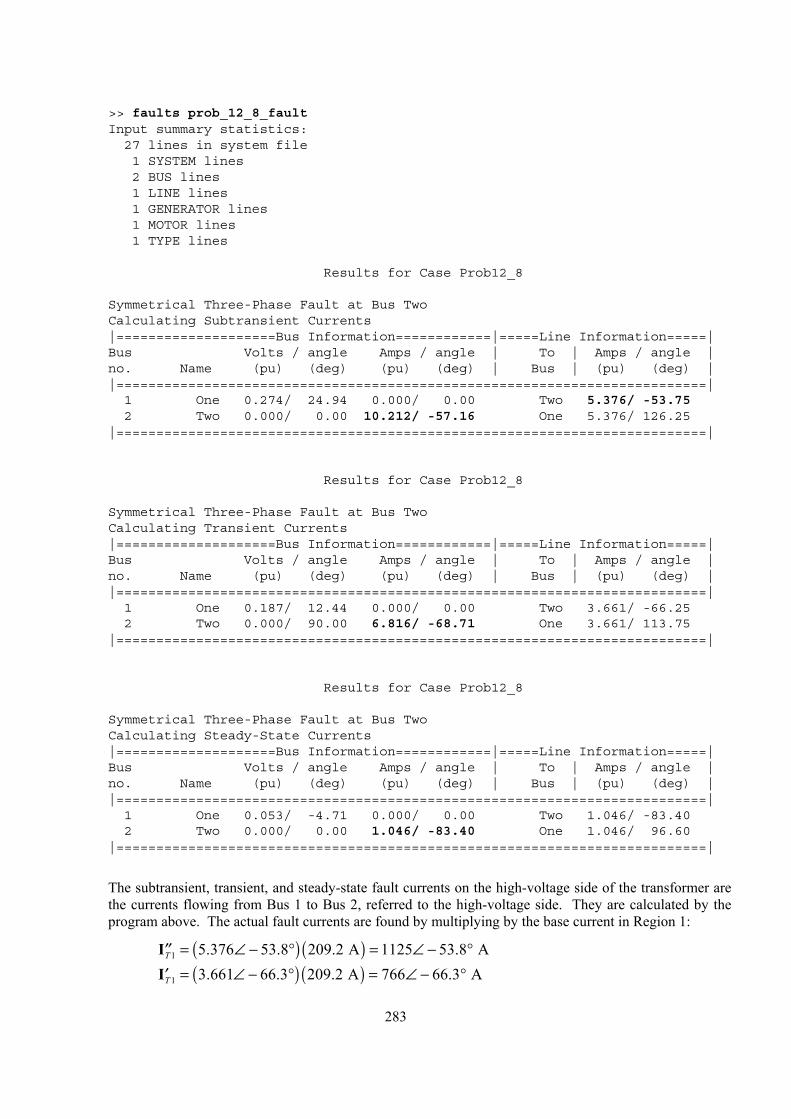
283
>> faults prob_12_8_faultInput summary statistics:27 lines in system file1 SYSTEM lines2 BUS lines1 LINE lines1 GENERATOR lines1 MOTOR lines1 TYPE lines
Results for Case Prob12_8
Symmetrical Three-Phase Fault at Bus TwoCalculating Subtransient Currents|====================Bus Information============|=====Line Information=====|Bus Volts / angle Amps / angle | To | Amps / angle |no. Name (pu) (deg) (pu) (deg) | Bus | (pu) (deg) ||==========================================================================|1 One 0.274/ 24.94 0.000/ 0.00 Two 5.376/ -53.752 Two 0.000/ 0.00 10.212/ -57.16 One 5.376/ 126.25
|==========================================================================|
Results for Case Prob12_8
Symmetrical Three-Phase Fault at Bus TwoCalculating Transient Currents|====================Bus Information============|=====Line Information=====|Bus Volts / angle Amps / angle | To | Amps / angle |no. Name (pu) (deg) (pu) (deg) | Bus | (pu) (deg) ||==========================================================================|1 One 0.187/ 12.44 0.000/ 0.00 Two 3.661/ -66.252 Two 0.000/ 90.00 6.816/ -68.71 One 3.661/ 113.75
|==========================================================================|
Results for Case Prob12_8
Symmetrical Three-Phase Fault at Bus TwoCalculating Steady-State Currents|====================Bus Information============|=====Line Information=====|Bus Volts / angle Amps / angle | To | Amps / angle |no. Name (pu) (deg) (pu) (deg) | Bus | (pu) (deg) ||==========================================================================|1 One 0.053/ -4.71 0.000/ 0.00 Two 1.046/ -83.402 Two 0.000/ 0.00 1.046/ -83.40 One 1.046/ 96.60
|==========================================================================|
The subtransient, transient, and steady-state fault currents on the high-voltage side of the transformer are the currents flowing from Bus 1 to Bus 2, referred to the high-voltage side. They are calculated by the program above. The actual fault currents are found by multiplying by the base current in Region 1:
( ) ( )1 5.376 53.8 209.2 A 1125 53.8 AT = ∠ − ° = ∠ − °′′I
( ) ( )1 3.661 66.3 209.2 A 766 66.3 AT = ∠ − ° = ∠ − °′I

284
( ) ( )1 1.046 83.4 209.2 A 219 83.4 AT = ∠ − ° = ∠ − °I
The subtransient, transient, and steady-state fault currents on the low-voltage side of the transformer are the fault currents flowing at Bus 2. They are calculated by the program above. The actual fault currents are found by multiplying by the base current in Region 2:
( ) ( )10.212 57.2 2092 A 21,360 57.2 Af = ∠ − ° = ∠ − °′′I
( ) ( )6.816 68.7 2092 A 14,260 68.7 Af = ∠ − ° = ∠ − °′I
( ) ( )1.046 83.4 2092 A 2188 83.4 Af = ∠ − ° = ∠ − °I
The subtransient, transient, and steady-state motor currents will be the currents that would flow in the motor if its terminals were short circuited. These per-unit currents will be 1.00/Z for the subtransient and transient cases, and zero for the steady-state case. (The current from the motor is 0 at steady state because there is nothing to keep the motor turning of the electrical input to the motor is shorted out.)
21.00 0 4.856 60.9 A
0.10 0.18M j∠ °= = ∠ − °′′
+I
21.00 0 3.162 71.6 A
0.10 0.30M j∠ °= = ∠ − °′′
+I
2 0 AM =I The actual motor currents are found by multiplying by the base current in Region 2:
( ) ( )2 4.856 60.9 2092 A 10,160 60.9 AM = ∠ − ° = ∠ − °′′I
( ) ( )2 3.162 71.6 2092 A 6615 71.6 AM = ∠ − ° = ∠ − °′I 2 0 AM =I
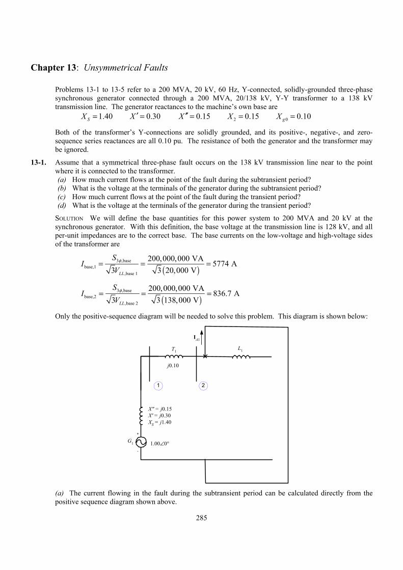
Chapter 13: Unsymmetrical Faults
Problems 13-1 to 13-5 refer to a 200 MVA, 20 kV, 60 Hz, Y-connected, solidly-grounded three-phase synchronous generator connected through a 200 MVA, 20/138 kV, Y-Y transformer to a 138 kV transmission line. The generator reactances to the machine’s own base are
1.40SX = 0.30X ′ = 0.15X ′′ = 2 0.15X = 0 0.10gX =
Both of the transformer’s Y-connections are solidly grounded, and its positive-, negative-, and zero-sequence series reactances are all 0.10 pu. The resistance of both the generator and the transformer may be ignored.
13-1. Assume that a symmetrical three-phase fault occurs on the 138 kV transmission line near to the point where it is connected to the transformer. (a) How much current flows at the point of the fault during the subtransient period? (b) What is the voltage at the terminals of the generator during the subtransient period? (c) How much current flows at the point of the fault during the transient period? (d) What is the voltage at the terminals of the generator during the transient period?
SOLUTION We will define the base quantities for this power system to 200 MVA and 20 kV at the synchronous generator. With this definition, the base voltage at the transmission line is 128 kV, and all per-unit impedances are to the correct base. The base currents on the low-voltage and high-voltage sides of the transformer are
( )
3 ,basebase,1
,base 1
200,000,000 VA 5774 A3 3 20,000 VLL
SV
φ= = =I
( )
3 ,basebase,2
,base 2
200,000,000 VA 836.7 A3 3 138,000 VLL
SV
φ= = =I
Only the positive-sequence diagram will be needed to solve this problem. This diagram is shown below:
G1
X" = j0.15X' = j0.30XS = j1.40
L1T1
j0.10
1.00∠0°
1 2
+
-
IA1
(a) The current flowing in the fault during the subtransient period can be calculated directly from the
positive sequence diagram shown above.
285
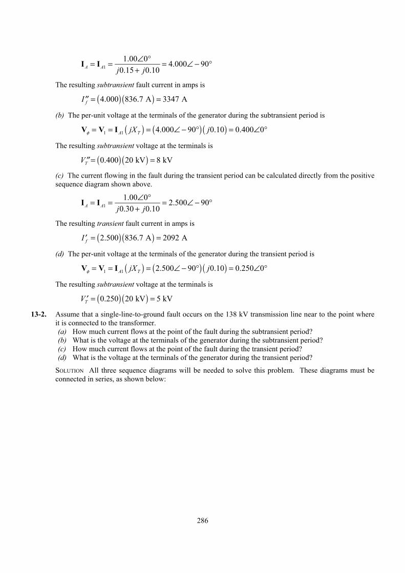
11.00 0 4.000 90
0.15 0.10A A j j∠ °= = = ∠ −
+°
°
I I
The resulting subtransient fault current in amps is
fI = =′′ ( ) ( )4.000 836.7 A 3347 A
(b) The per-unit voltage at the terminals of the generator during the subtransient period is
V V ( ) ( ) ( )1 1 4.000 90 0.10 0.400 0A TjX jφ = = = ∠ − ° = ∠I
The resulting subtransient voltage at the terminals is
V = = ( ) ( )0.400 20 kV 8 kVT′′
(c) The current flowing in the fault during the transient period can be calculated directly from the positive sequence diagram shown above.
11.00 0 2.500 90
0.30 0.10A A j j∠ °= = = ∠ −
+°
°
I I
The resulting transient fault current in amps is
fI = =′ ( ) ( )2.500 836.7 A 2092 A
(d) The per-unit voltage at the terminals of the generator during the transient period is
V V ( ) ( ) ( )1 1 2.500 90 0.10 0.250 0A TjX jφ = = = ∠ − ° = ∠I
The resulting subtransient voltage at the terminals is
V = =′ ( ) ( )0.250 20 kV 5 kVT
13-2. Assume that a single-line-to-ground fault occurs on the 138 kV transmission line near to the point where it is connected to the transformer. (a) How much current flows at the point of the fault during the subtransient period? (b) What is the voltage at the terminals of the generator during the subtransient period? (c) How much current flows at the point of the fault during the transient period? (d) What is the voltage at the terminals of the generator during the transient period?
SOLUTION All three sequence diagrams will be needed to solve this problem. These diagrams must be connected in series, as shown below:
286
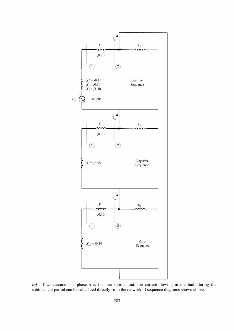
G1
X" = j0.15X' = j0.30XS = j1.40
L1T1
j0.10
1.00∠0°
1 2
+
-
IA1
X2 = j0.15
L1T1
j0.10
1 2
IA2
Xg0 = j0.10
L1T1
j0.10
1 2
IA0
PositiveSequence
NegativeSequence
Zero Sequence
(a) If we assume that phase a is the one shorted out, the current flowing in the fault during the
subtransient period can be calculated directly from the network of sequence diagrams shown above.
287
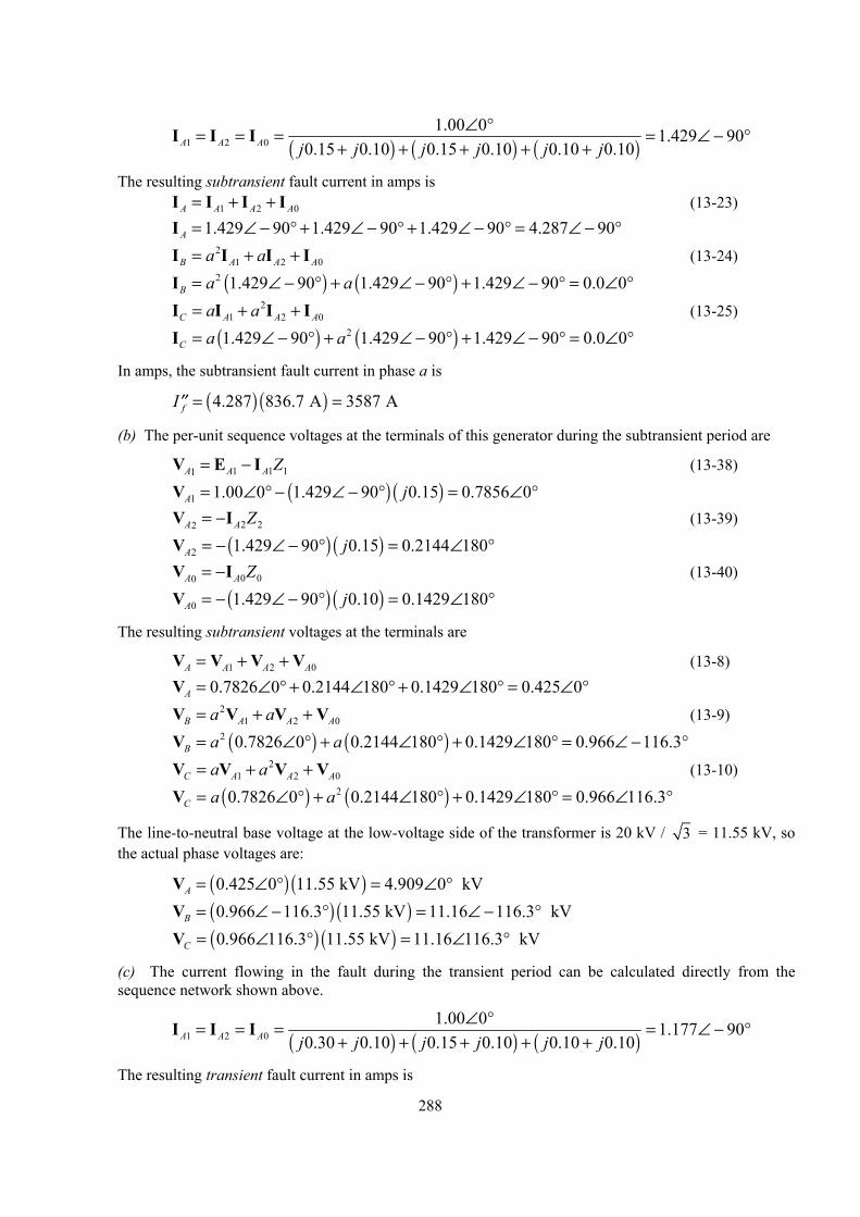
( ) ( ) ( )1 2 01.00 0 1.429 90
0.15 0.10 0.15 0.10 0.10 0.10A A A j j j j j j∠ °= = = = ∠ −
+ + + + +I °
0
I I
The resulting subtransient fault current in amps is 1 2A A A= + +I IA
0A
°
0A
°
1
I I (13-23) =I 1.429 90 1.429 90 1.429 90 4.287 90A ∠ − ° + ∠ − ° + ∠ − ° = ∠ − ° I I (13-24) 2
1 2B A Aa a= + +I I =I ( ) ( )2 1.429 90 1.429 90 1.429 90 0.0 0B a a∠ − ° + ∠ − ° + ∠ − ° = ∠ I I (13-25) 2
1 2C A Aa a= + +I I =I ( ) ( )21.429 90 1.429 90 1.429 90 0.0 0C a a∠ − ° + ∠ − ° + ∠ − ° = ∠
In amps, the subtransient fault current in phase a is
fI = =′′ ( ) ( )4.287 836.7 A 3587 A
(b) The per-unit sequence voltages at the terminals of this generator during the subtransient period are
1 11A A A Z= − IV E (13-38)
= ∠V ( ) ( )1 1.00 0 1.429 90 0.15 0.7856 0A j° − ∠ − ° = ∠ ° 2 22A A Z= −IV (13-39)
= −V ( ) ( )2 1.429 90 0.15 0.2144 180A j∠ − ° = ∠ ° 0 00A A Z= −IV (13-40)
= −V ( ) ( )0 1.429 90 0.10 0.1429 180A j∠ − ° = ∠ °
The resulting subtransient voltages at the terminals are
1 2 0A A A= + +V VA
°
0A
°
0A
°
V V (13-8) = ∠V 0.7826 0 0.2144 180 0.1429 180 0.425 0A ° + ∠ ° + ∠ ° = ∠ V V (13-9) 2
1 2B A Aa a= + +V V = ∠V ( ) ( )2 0.7826 0 0.2144 180 0.1429 180 0.966 116.3B a a° + ∠ ° + ∠ ° = ∠ − V V (13-10) 2
1 2C A Aa a= + +V V = ∠V ( ) ( )20.7826 0 0.2144 180 0.1429 180 0.966 116.3C a a° + ∠ ° + ∠ ° = ∠
The line-to-neutral base voltage at the low-voltage side of the transformer is 20 kV / 3 = 11.55 kV, so the actual phase voltages are:
= ∠V ( ) ( )0.425 0 11.55 kV 4.909 0 kVA ° = ∠ ° =V ( ) ( )0.966 116.3 11.55 kV 11.16 116.3 kVB ∠ − ° = ∠ − ° = ∠V ( ) ( )0.966 116.3 11.55 kV 11.16 116.3 kVC ° = ∠ °
(c) The current flowing in the fault during the transient period can be calculated directly from the sequence network shown above.
( ) ( ) ( )1 2 01.00 0 1.177 90
0.30 0.10 0.15 0.10 0.10 0.10A A A j j j j j j∠ °= = = = ∠ −
+ + + + +I °I I
The resulting transient fault current in amps is
288
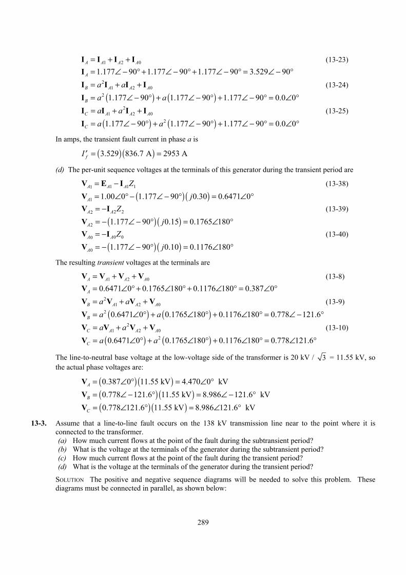
1 2 0A A A= + +I IA
0A
°
0A
°
1
I I (13-23) =I 1.177 90 1.177 90 1.177 90 3.529 90A ∠ − ° + ∠ − ° + ∠ − ° = ∠ − ° I I (13-24) 2
1 2B A Aa a= + +I I =I ( ) ( )2 1.177 90 1.177 90 1.177 90 0.0 0B a a∠ − ° + ∠ − ° + ∠ − ° = ∠ I I (13-25) 2
1 2C A Aa a= + +I I =I ( ) ( )21.177 90 1.177 90 1.177 90 0.0 0C a a∠ − ° + ∠ − ° + ∠ − ° = ∠
In amps, the transient fault current in phase a is
fI = =′ ( ) ( )3.529 836.7 A 2953 A
(d) The per-unit sequence voltages at the terminals of this generator during the transient period are
1 11A A A Z= − IV E (13-38)
= ∠V ( ) ( )1 1.00 0 1.177 90 0.30 0.6471 0A j° − ∠ − ° = ∠ ° 2 22A A Z= −IV (13-39)
= −V ( ) ( )2 1.177 90 0.15 0.1765 180A j∠ − ° = ∠ ° 0 00A A Z= −IV (13-40)
= −V ( ) ( )0 1.177 90 0.10 0.1176 180A j∠ − ° = ∠ °
The resulting transient voltages at the terminals are
1 2 0A A A= + +V VA
°
0A
°
0A
°
V V (13-8) = ∠V 0.6471 0 0.1765 180 0.1176 180 0.387 0A ° + ∠ ° + ∠ ° = ∠ V V (13-9) 2
1 2B A Aa a= + +V V = ∠V ( ) ( )2 0.6471 0 0.1765 180 0.1176 180 0.778 121.6B a a° + ∠ ° + ∠ ° = ∠ − V V (13-10) 2
1 2C A Aa a= + +V V = ∠V ( ) ( )20.6471 0 0.1765 180 0.1176 180 0.778 121.6C a a° + ∠ ° + ∠ ° = ∠
The line-to-neutral base voltage at the low-voltage side of the transformer is 20 kV / 3 = 11.55 kV, so the actual phase voltages are:
= ∠V ( ) ( )0.387 0 11.55 kV 4.470 0 kVA ° = ∠ ° =V ( ) ( )0.778 121.6 11.55 kV 8.986 121.6 kVB ∠ − ° = ∠ − ° = ∠V ( ) ( )0.778 121.6 11.55 kV 8.986 121.6 kVC ° = ∠ °
13-3. Assume that a line-to-line fault occurs on the 138 kV transmission line near to the point where it is connected to the transformer. (a) How much current flows at the point of the fault during the subtransient period? (b) What is the voltage at the terminals of the generator during the subtransient period? (c) How much current flows at the point of the fault during the transient period? (d) What is the voltage at the terminals of the generator during the transient period?
SOLUTION The positive and negative sequence diagrams will be needed to solve this problem. These diagrams must be connected in parallel, as shown below:
289
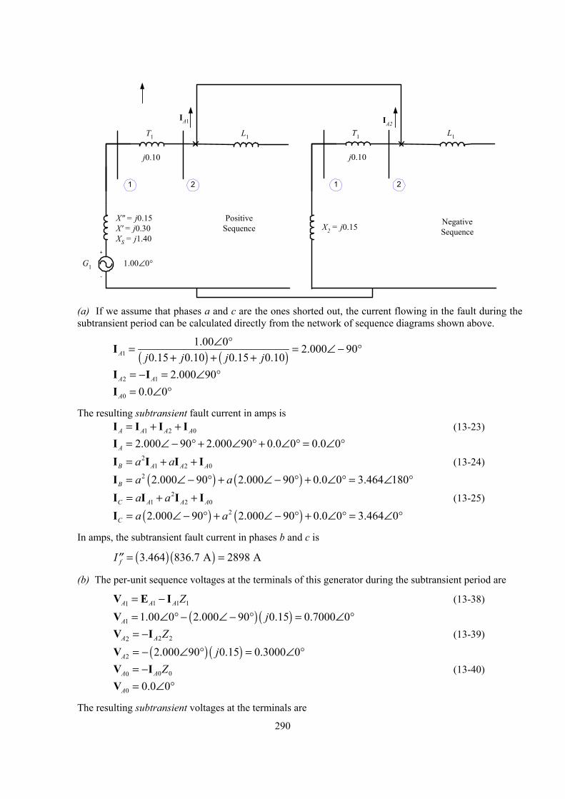
G1
X" = j0.15X' = j0.30XS = j1.40
L1T1
j0.10
1.00∠0°
1 2
+
-
IA1
PositiveSequence X2 = j0.15
L1T1
j0.10
1 2
IA2
NegativeSequence
(a) If we assume that phases a and c are the ones shorted out, the current flowing in the fault during the
subtransient period can be calculated directly from the network of sequence diagrams shown above.
( ) ( )11.00 0 2.000 90
0.15 0.10 0.15 0.10A j j j j∠ °
+ + += =I ∠ − °
°
0
I I 2 1 2.000 90A A= − = ∠ ° =I 0 0.0 0A ∠
The resulting subtransient fault current in amps is 1 2A A A= + +I IA
°
0A
°
0A
∠ °
1
I I (13-23) = ∠I 2.000 90 2.000 90 0.0 0 0.0 0A − ° + ∠ ° + ∠ ° = ∠ I I (13-24) 2
1 2B A Aa a= + +I I =I ( ) ( )2 2.000 90 2.000 90 0.0 0 3.464 180B a a∠ − ° + ∠ − ° + ∠ ° = ∠ I I (13-25) 2
1 2C A Aa a= + +I I = ∠I ( ) ( )22.000 90 2.000 90 0.0 0 3.464 0C a a− ° + ∠ − ° + ∠ ° =
In amps, the subtransient fault current in phases b and c is
fI = =′′ ( ) ( )3.464 836.7 A 2898 A
(b) The per-unit sequence voltages at the terminals of this generator during the subtransient period are
1 11A A A Z= − IV E (13-38)
= ∠V ( ) ( )1 1.00 0 2.000 90 0.15 0.7000 0A j° − ∠ − ° = ∠ ° 2 22A A Z= −IV (13-39)
= −V ( ) ( )2 2.000 90 0.15 0.3000 0A j∠ ° = ∠ ° 0 00A A Z= −IV (13-40) =V 0 0.0 0A ∠ °
The resulting subtransient voltages at the terminals are
290
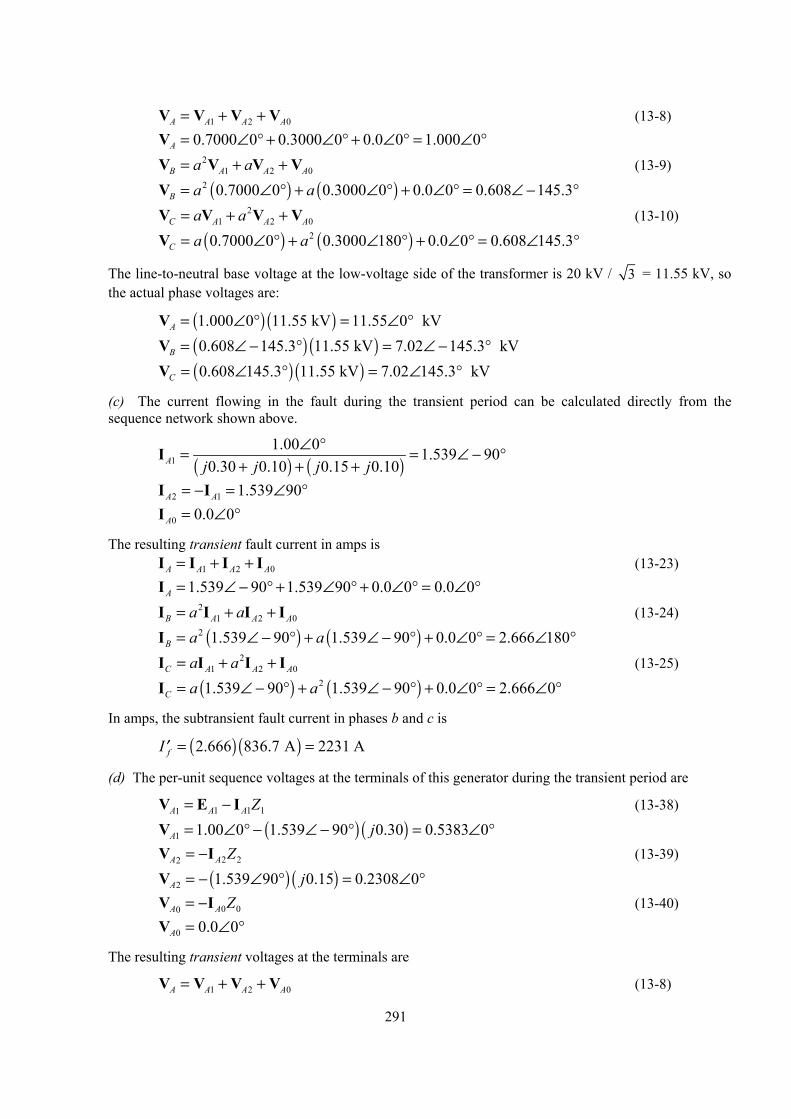
1 2 0A A A= + +V VA
0A
°
0A
°
V V (13-8) =V 0.7000 0 0.3000 0 0.0 0 1.000 0A ∠ ° + ∠ ° + ∠ ° = ∠ ° V V (13-9) 2
1 2B A Aa a= + +V V = ∠V ( ) ( )2 0.7000 0 0.3000 0 0.0 0 0.608 145.3B a a° + ∠ ° + ∠ ° = ∠ − V V (13-10) 2
1 2C A Aa a= + +V V = ∠V ( ) ( )20.7000 0 0.3000 180 0.0 0 0.608 145.3C a a° + ∠ ° + ∠ ° = ∠
The line-to-neutral base voltage at the low-voltage side of the transformer is 20 kV / 3 = 11.55 kV, so the actual phase voltages are:
= ∠V ( ) ( )1.000 0 11.55 kV 11.55 0 kVA ° = ∠ ° =V ( ) ( )0.608 145.3 11.55 kV 7.02 145.3 kVB ∠ − ° = ∠ − ° = ∠V ( ) ( )0.608 145.3 11.55 kV 7.02 145.3 kVC ° = ∠ °
(c) The current flowing in the fault during the transient period can be calculated directly from the sequence network shown above.
( ) ( )11.00 0 1.539 90
0.30 0.10 0.15 0.10A j j j j∠ °
+ + += =I ∠ − °
°
0
I I 2 1 1.539 90A A= − = ∠ ° =I 0 0.0 0A ∠
The resulting transient fault current in amps is 1 2A A A= + +I IA
°
0A
°
0A
°
1
I I (13-23) = ∠I 1.539 90 1.539 90 0.0 0 0.0 0A − ° + ∠ ° + ∠ ° = ∠ I I (13-24) 2
1 2B A Aa a= + +I I = ∠I ( ) ( )2 1.539 90 1.539 90 0.0 0 2.666 180B a a− ° + ∠ − ° + ∠ ° = ∠ I I (13-25) 2
1 2C A Aa a= + +I I =I ( ) ( )21.539 90 1.539 90 0.0 0 2.666 0C a a∠ − ° + ∠ − ° + ∠ ° = ∠
In amps, the subtransient fault current in phases b and c is
fI = =′ ( ) ( )2.666 836.7 A 2231 A
(d) The per-unit sequence voltages at the terminals of this generator during the transient period are
1 11A A A Z= − IV E (13-38)
= ∠V ( ) ( )1 1.00 0 1.539 90 0.30 0.5383 0A j° − ∠ − ° = ∠ ° 2 22A A Z= −IV (13-39)
= −V ( ) ( )2 1.539 90 0.15 0.2308 0A j∠ ° = ∠ ° 0 00A A Z= −IV (13-40) =V 0 0.0 0A ∠ °
0
The resulting transient voltages at the terminals are
1 2A A A= + +V VAV V (13-8)
291
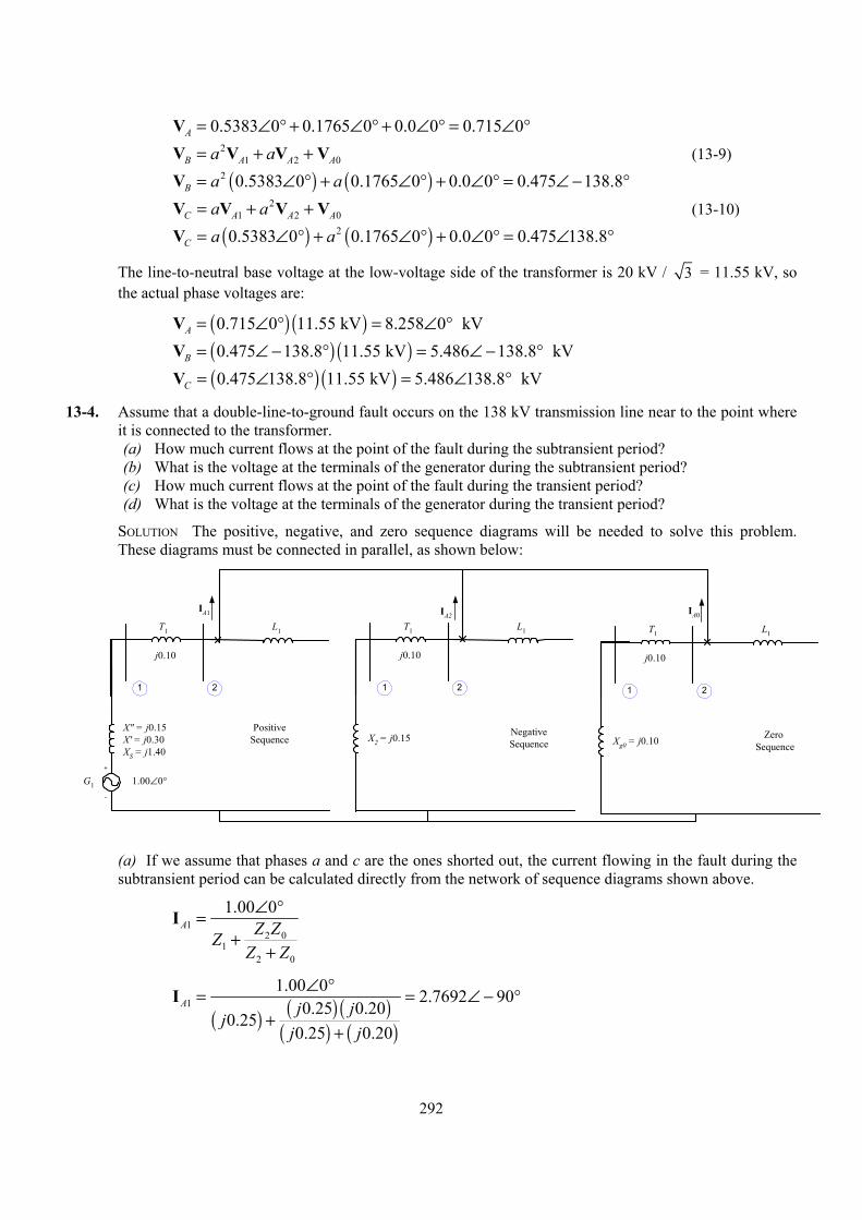
=V 0.5383 0 0.1765 0 0.0 0 0.715 0A ∠ ° + ∠ ° + ∠ ° = ∠ ° V V (13-9) 2
1 2B A Aa a= + +V V 0A
°
0A
°
= ∠V ( ) ( )2 0.5383 0 0.1765 0 0.0 0 0.475 138.8B a a° + ∠ ° + ∠ ° = ∠ − V V (13-10) 2
1 2C A Aa a= + +V V = ∠V ( ) ( )20.5383 0 0.1765 0 0.0 0 0.475 138.8C a a° + ∠ ° + ∠ ° = ∠
The line-to-neutral base voltage at the low-voltage side of the transformer is 20 kV / 3 = 11.55 kV, so the actual phase voltages are:
= ∠V ( ) ( )0.715 0 11.55 kV 8.258 0 kVA ° = ∠ ° = ∠V ( ) ( )0.475 138.8 11.55 kV 5.486 138.8 kVB − ° = ∠ − ° = ∠V ( ) ( )0.475 138.8 11.55 kV 5.486 138.8 kVC ° = ∠ °
13-4. Assume that a double-line-to-ground fault occurs on the 138 kV transmission line near to the point where it is connected to the transformer. (a) How much current flows at the point of the fault during the subtransient period? (b) What is the voltage at the terminals of the generator during the subtransient period? (c) How much current flows at the point of the fault during the transient period? (d) What is the voltage at the terminals of the generator during the transient period?
SOLUTION The positive, negative, and zero sequence diagrams will be needed to solve this problem. These diagrams must be connected in parallel, as shown below:
G1
X" = j0.15X' = j0.30XS = j1.40
L1T1
j0.10
1.00∠0°
1 2
+
-
IA1
PositiveSequence X2 = j0.15
L1T1
j0.10
1 2
IA2
NegativeSequence Xg0 = j0.10
L1T1
j0.10
1 2
IA0
Zero Sequence
(a) If we assume that phases a and c are the ones shorted out, the current flowing in the fault during the subtransient period can be calculated directly from the network of sequence diagrams shown above.
12 0
12 0
1.00 0A Z ZZ
Z Z
∠ °
++
=I
( ) ( ) ( )
( ) ( )1
1.00 0 2.7692 900.25 0.20
0.250.25 0.20
A j jj
j j
∠ °
++
= =I ∠ − °
292
( )02 1
2 0
0.202.7692 90 1.2308 900.25 0.20A A
Z jZ Z j j
= − = − ∠ − ° = ∠ °+ +
I I
( )20 1
2 0
0.252.7692 90 1.5385 900.25 0.20A A
Z jZ Z j j
= − = − ∠ − ° = ∠ °+ +
I I
The resulting subtransient fault current in amps is 1 2 0A A A= + +I IA
°
0A
°
0A
°
1
I I (13-23) = ∠I 2.7692 90 1.2308 90 1.5385 90 0.0 0A − ° + ∠ ° + ∠ ° = ∠ I I (13-24) 2
1 2B A Aa a= + +I I = ∠I ( ) ( )2 2.7692 90 1.2308 90 1.5385 90 4.162 146.3B a a− ° + ∠ ° + ∠ ° = ∠ I I (13-25) 2
1 2C A Aa a= + +I I = ∠I ( ) ( )22.7692 90 1.2308 90 1.5385 90 4.162 33.7C a a− ° + ∠ ° + ∠ ° = ∠
In amps, the subtransient fault current in phases b and c is
fI = =′′ ( ) ( )4.162 836.7 A 3482 A
(b) The per-unit sequence voltages at the terminals of this generator during the subtransient period are
1 11A A A Z= − IV E (13-38)
= ∠V ( ) ( )1 1.00 0 2.7692 90 0.15 0.5846 0A j° − ∠ − ° = ∠ ° 2 22A A Z= −IV (13-39)
= −V ( ) ( )2 1.2308 90 0.15 0.1846 0A j∠ ° = ∠ ° 0 00A A Z= −IV (13-40)
= −V ( ) ( )0 1.5385 90 0.10 0.1539 0A j∠ ° = ∠ °
The resulting subtransient voltages at the terminals are
1 2 0A A A= + +V VA
0A
°
0A
°
V V (13-8) =V 0.5846 0 0.1846 0 0.1539 0 0.923 0A ∠ ° + ∠ ° + ∠ ° = ∠ ° V V (13-9) 2
1 2B A Aa a= + +V V = ∠V ( ) ( )2 0.5846 0 0.1846 0 0.1539 0 0.416 123.7B a a° + ∠ ° + ∠ ° = ∠ − V V (13-10) 2
1 2C A Aa a= + +V V = ∠V ( ) ( )20.5846 0 0.1846 0 0.1539 0 0.416 123.7C a a° + ∠ ° + ∠ ° = ∠
The line-to-neutral base voltage at the low-voltage side of the transformer is 20 kV / 3 = 11.55 kV, so the actual phase voltages are:
= ∠V ( ) ( )0.923 0 11.55 kV 10.66 0 kVA ° = ∠ ° =V ( ) ( )0.416 123.7 11.55 kV 4.81 145.3 kVB ∠ − ° = ∠ − ° = ∠V ( ) ( )0.416 123.7 11.55 kV 4.81 123.7 kVC ° = ∠ °
(c) The current flowing in the fault during the transient period can be calculated directly from the sequence network shown above.
293
12 0
12 0
1.00 0A Z ZZ
Z Z
∠ °
++
=I
( ) ( ) ( )
( ) ( )1
1.00 0 1.9565 900.25 0.20
0.400.25 0.20
A j jj
j j
∠ °
++
= =I ∠ − °
( )02 1
2 0
0.201.9565 90 0.8696 900.25 0.20A A
Z jZ Z j j
= − = − ∠ − ° = ∠ °+ +
I I
( )20 1
2 0
0.251.9565 90 1.0870 900.25 0.20A A
Z jZ Z j j
= − = − ∠ − ° = ∠ °+ +
I I
The resulting transient fault current in amps is 1 2 0A A A= + +I IA
°
0A
°
0A
°
1
I I (13-23) = ∠I 1.9565 90 0.8696 90 1.0870 90 0.0 0A − ° + ∠ ° + ∠ ° = ∠ I I (13-24) 2
1 2B A Aa a= + +I I = ∠I ( ) ( )2 1.9565 90 0.8696 90 1.0870 90 2.941 146.3B a a− ° + ∠ ° + ∠ ° = ∠ I I (13-25) 2
1 2C A Aa a= + +I I = ∠I ( ) ( )21.9565 90 0.8696 90 1.0870 90 2.941 33.7C a a− ° + ∠ ° + ∠ ° = ∠
In amps, the subtransient fault current in phases b and c is
fI = =′ ( ) ( )2.941 836.7 A 2461 A
(d) The per-unit sequence voltages at the terminals of this generator during the transient period are
1 11A A A Z= − IV E (13-38)
= ∠V ( ) ( )1 1.00 0 1.9565 90 0.30 0.4130 0A j° − ∠ − ° = ∠ ° 2 22A A Z= −IV (13-39)
= −V ( ) ( )2 0.8696 90 0.15 0.1304 0A j∠ ° = ∠ ° 0 00A A Z= −IV (13-40)
= −V ( ) ( )0 1.0870 90 0.10 0.1087 0A j∠ ° = ∠ °
The resulting transient voltages at the terminals are
1 2 0A A A= + +V VA
°
0A
°
0A
°
V V (13-8) = ∠V 0.4130 0 0.1304 0 0.1087 0 0.652 0A ° + ∠ ° + ∠ ° = ∠ V V (13-9) 2
1 2B A Aa a= + +V V = ∠V ( ) ( )2 0.4130 0 0.1304 0 0.1087 0 0.294 123.7B a a° + ∠ ° + ∠ ° = ∠ − V V (13-10) 2
1 2C A Aa a= + +V V = ∠V ( ) ( )20.4130 0 0.1304 0 0.1087 0 0.294 123.7C a a° + ∠ ° + ∠ ° = ∠
The line-to-neutral base voltage at the low-voltage side of the transformer is 20 kV / 3 = 11.55 kV, so the actual phase voltages are:
294
= ∠V ( ) ( )0.652 0 11.55 kV 7.531 0 kVA ° = ∠ ° =V ( ) ( )0.294 123.7 11.55 kV 3.396 123.7 kVB ∠ − ° = ∠ − ° = ∠V ( ) ( )0.294 123.7 11.55 kV 3.396 123.7 kVC ° = ∠ °
13-5. Suppose the transformer in this power system is changed from a Y-Y to a Y-∆, with the Y-connection solidly grounded. Nothing else changes in the power system. Now suppose that a single-line-to-ground fault occurs on the 138 kV transmission line near to the point where it is connected to the transformer. (a) How much current flows at the point of the fault during the subtransient period? (b) What is the voltage at the terminals of the generator during the subtransient period? (c) How much current flows at the point of the fault during the transient period? (d) What is the voltage at the terminals of the generator during the transient period?
SOLUTION All three sequence diagrams will be needed to solve this problem. The positive and negative sequence diagrams are the same as in the previous three problems. The zero sequence diagram is different because the connectivity of the transformer has changed. These three sequence diagrams must be connected in series, as shown below:
295
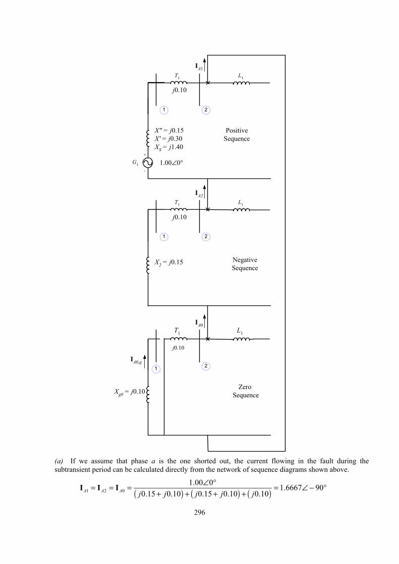
G1
X" = j0.15X' = j0.30XS = j1.40
L1T1
j0.10
1.00∠0°
1 2
+
-
IA1
X2 = j0.15
L1T1
j0.10
1 2
IA2
Xg0 = j0.10
L1T1
j0.10
1 2
IA0
PositiveSequence
NegativeSequence
Zero Sequence
IA0,g
(a) If we assume that phase a is the one shorted out, the current flowing in the fault during the
subtransient period can be calculated directly from the network of sequence diagrams shown above.
( ) ( ) ( )1 2 01.00 0 1.6667 90
0.15 0.10 0.15 0.10 0.10A A A j j j j j∠ °= = = = ∠ −
+ + + +I °I I
296
The resulting subtransient fault current in amps is 1 2 0A A A= + +I IA
0A
°
0A
°
1
I I (13-23) =I 1.6667 90 1.6667 90 1.6667 90 5.000 90A ∠ − ° + ∠ − ° + ∠ − ° = ∠ − ° I I (13-24) 2
1 2B A Aa a= + +I I =I ( ) ( )2 1.6667 90 1.6667 90 1.6667 90 0.0 0B a a∠ − ° + ∠ − ° + ∠ − ° = ∠ I I (13-25) 2
1 2C A Aa a= + +I I =I ( ) ( )21.6667 90 1.6667 90 1.6667 90 0.0 0C a a∠ − ° + ∠ − ° + ∠ − ° = ∠
In amps, the subtransient fault current in phase a is
fI = =′′ ( ) ( )5.000 836.7 A 4184 A
(b) The per-unit sequence voltages at the terminals of this generator during the subtransient period are given below. Note that the zero sequence current we need here is the zero sequence current through the generator, which is zero.
1 11A A A Z= − IV E (13-38)
= ∠V ( ) ( )1 1.00 0 1.6667 90 0.15 0.7500 0A j° − ∠ − ° = ∠ ° 2 22A A Z= −IV (13-39)
= −V ( ) ( )2 1.6667 90 0.15 0.2500 180A j∠ − ° = ∠ ° 0 0,A A g 0Z= −V I (13-40)
=V 0 0.0 0A ∠ °
0
The resulting subtransient voltages at the terminals are
1 2A A A= + +V VA
°
0A
°
0A
°
V V (13-8) = ∠V 0.7500 0 0.2500 180 0.0 0 0.500 0A ° + ∠ ° + ∠ ° = ∠ V V (13-9) 2
1 2B A Aa a= + +V V = ∠V ( ) ( )2 0.7500 0 0.2500 180 0.0 0 0.9014 106.1B a a° + ∠ ° + ∠ ° = ∠ − V V (13-10) 2
1 2C A Aa a= + +V V = ∠V ( ) ( )20.7500 0 0.2500 180 0.0 0 0.9014 106.1C a a° + ∠ ° + ∠ ° = ∠
The line-to-neutral base voltage at the low-voltage side of the transformer is 20 kV / 3 = 11.55 kV, so the actual phase voltages are:
= ∠V ( ) ( )0.500 0 11.55 kV 5.775 0 kVA ° = ∠ ° =V ( ) ( )0.9014 106.1 11.55 kV 10.41 106.1 kVB ∠ − ° = ∠ − ° = ∠V ( ) ( )0.9014 106.1 11.55 kV 10.41 106.1 kVC ° = ∠ °
(c) The current flowing in the fault during the transient period can be calculated directly from the sequence network shown above.
( ) ( ) ( )1 2 01.00 0 1.3333 90
0.30 0.10 0.15 0.10 0.10A A A j j j j j∠ °= = = = ∠ −
+ + + +I °
0
I I
The resulting transient fault current in amps is 1 2A A A= + +I IAI I (13-23)
297
=I 1.3333 90 1.3333 90 1.3333 90 4.0000 90A ∠ − ° + ∠ − ° + ∠ − ° = ∠ − ° I I (13-24) 2
1 2B A Aa a= + +I I 0A
°
0A
°
1
=I ( ) ( )2 1.3333 90 1.3333 90 1.3333 90 0.0 0B a a∠ − ° + ∠ − ° + ∠ − ° = ∠ I I (13-25) 2
1 2C A Aa a= + +I I =I ( ) ( )21.3333 90 1.3333 90 1.3333 90 0.0 0C a a∠ − ° + ∠ − ° + ∠ − ° = ∠
In amps, the transient fault current in phase a is
fI = =′ ( ) ( )4.000 836.7 A 3347 A
(d) The per-unit sequence voltages at the terminals of this generator during the transient period are given below. Note that the zero sequence current we need here is the zero sequence current through the generator, which is zero.
1 11A A A Z= − IV E (13-38)
= ∠V ( ) ( )1 1.00 0 1.3333 90 0.30 0.6000 0A j° − ∠ − ° = ∠ ° 2 22A A Z= −IV (13-39)
= −V ( ) ( )2 1.3333 90 0.15 0.4000 180A j∠ − ° = ∠ ° 0 0,A A g 0Z= −V I (13-40)
=V 0 0.0 0A ∠ °
0
The resulting transient voltages at the terminals are
1 2A A A= + +V VA
°
0A
°
0A
°
V V (13-8) = ∠V 0.6000 0 0.4000 180 0.0 0 0.2000 0A ° + ∠ ° + ∠ ° = ∠ V V (13-9) 2
1 2B A Aa a= + +V V = ∠V ( ) ( )2 0.6000 0 0.4000 180 0.0 0 0.8718 96.6B a a° + ∠ ° + ∠ ° = ∠ − V V (13-10) 2
1 2C A Aa a= + +V V = ∠V ( ) ( )20.6000 0 0.4000 180 0.0 0 0.8718 96.6C a a° + ∠ ° + ∠ ° = ∠
The line-to-neutral base voltage at the low-voltage side of the transformer is 20 kV / 3 = 11.55 kV, so the actual phase voltages are:
= ∠V ( ) ( )0.2000 0 11.55 kV 2.310 0 kVA ° = ∠ ° =V ( ) ( )0.8718 96.6 11.55 kV 10.07 96.6 kVB ∠ − ° = ∠ − ° = ∠V ( ) ( )0.8718 96.6 11.55 kV 10.07 96.6 kVC ° = ∠ °
13-6. A simple three-phase power system is shown in Figure P13-1. Assume that the ratings of the various devices in this system are as follows:
Generator G : 250 MVA, 13.8 kV, R = 0.1 pu, 1 X ′′ = 0.18 pu, X ′ = 0.40 pu, pu, 2 0.15X = 0gX = 0.10 pu. This generator is grounded
through an impedance NZ = j0.20 pu. Generator G : 500 MVA, 20.0 kV, R = 0.1 pu, 2 X ′′ = 0.15 pu, X ′ = 0.35 pu
pu, 2 0.15X = 0gX = 0.10 pu. This generator is grounded
through an impedance NZ = j0.20 pu.
298
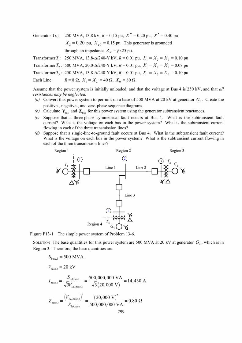
Generator G : 250 MVA, 13.8 kV, R = 0.15 pu, 3 X ′′ = 0.20 pu, X ′ = 0.40 pu pu, 2 0.20X = 0gX = 0.15 pu. This generator is grounded
through an impedance NZ = j0.25 pu. TransformerT : 250 MVA, 13.8-∆/240-Y kV, R = 0.01 pu, 1 1 2 0X X X= = = 0.10 pu TransformerT : 500 MVA, 20.0-∆/240-Y kV, R = 0.01 pu, 2 1 2 0X X X= = = 0.08 pu TransformerT : 250 MVA, 13.8-∆/240-Y kV, R = 0.01 pu, 3 1 2 0X X X= = = 0.10 pu Each Line: R = 8 Ω, 1 2X X= = 40 Ω, 0X = 80 Ω.
Assume that the power system is initially unloaded, and that the voltage at Bus 4 is 250 kV, and that all resistances may be neglected. (a) Convert this power system to per-unit on a base of 500 MVA at 20 kV at generator . Create the
positive-, negative-, and zero-phase sequence diagrams. 2G
(b) Calculate busY and busZ for this power system using the generator subtransient reactances. (c) Suppose that a three-phase symmetrical fault occurs at Bus 4. What is the subtransient fault
current? What is the voltage on each bus in the power system? What is the subtransient current flowing in each of the three transmission lines?
(d) Suppose that a single-line-to-ground fault occurs at Bus 4. What is the subtransient fault current? What is the voltage on each bus in the power system? What is the subtransient current flowing in each of the three transmission lines?
1 23
4
G3
T3
G2T2
Line 1 Line 2
Line 3
T1
Region 1 Region 2 Region 3
Region 4
Figure P13-1 The simple power system of Problem 13-6.
SOLUTION The base quantities for this power system are 500 MVA at 20 kV at generator G , which is in Region 3. Therefore, the base quantities are:
2
S base,3 500 MVA=
V base,3 20 kV=
( )
3 ,basebase,3
,base 3
500,000,000 VA 14,430 A3 3 20,000 VLL
SV
φ= = =I
( ) ( )
2 2,base 3
base,33 ,base
20,000 V0.80
500,000,000 VALLVS φ
= = =Z Ω
299
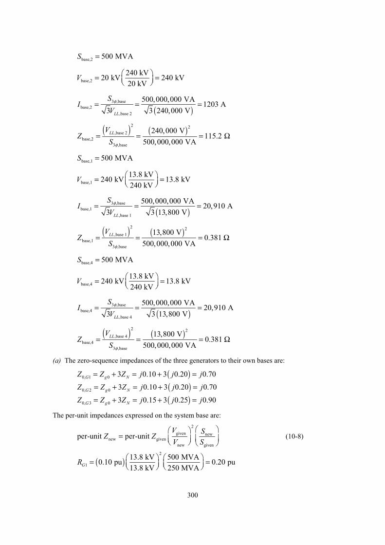
S base,2 500 MVA=
base,2240 kV20 kV 240 kV20 kV
= = V
( )
3 ,basebase,2
,base 2
500,000,000 VA 1203 A3 3 240,000 VLL
SV
φ= = =I
( ) ( )
2 2,base 2
base,23 ,base
240,000 V115.2
500,000,000 VALLVS φ
= = =Z Ω
S base,1 500 MVA=
base,113.8 kV240 kV 13.8 kV240 kV
= = V
( )
3 ,basebase,1
,base 1
500,000,000 VA 20,910 A3 3 13,800 VLL
SV
φ= = =I
( ) ( )
2 2,base 1
base,13 ,base
13,800 V0.381
500,000,000 VALLVS φ
= = =Z Ω
S base,4 500 MVA=
base,413.8 kV240 kV 13.8 kV240 kV
= = V
( )
3 ,basebase,4
,base 4
500,000,000 VA 20,910 A3 3 13,800 VLL
SV
φ= = =I
( ) ( )
2 2,base 4
base,43 ,base
13,800 V0.381
500,000,000 VALLVS φ
= = =Z Ω
(a) The zero-sequence impedances of the three generators to their own bases are:
Z Z ( )0, 1 0 3 0.10 3 0.20 0.70G g NZ j j j= + = + =
Z Z ( )0, 2 0 3 0.10 3 0.20 0.70G g NZ j j j= + = + =
Z Z ( )0, 3 0 3 0.15 3 0.25 0.90G g NZ j j j= + = + =
The per-unit impedances expressed on the system base are:
2
given newnew given
new given
r-unit per-unit V SZ ZV S
=
pe (10-8)
( )2
113.8 kV 500 MVA0.10 pu 0.20 pu13.8 kV 250 MVAG
R = =
300
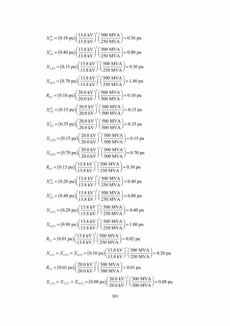
( )2
113.8 kV 500 MVA0.18 pu 0.36 pu13.8 kV 250 MVAG ′′
X = =
( )2
113.8 kV 500 MVA0.40 pu 0.80 pu13.8 kV 250 MVAG ′
X = =
( )2
2, 113.8 kV 500 MVA0.15 pu 0.30 pu13.8 kV 250 MVAG = =
X
( )2
0, 113.8 kV 500 MVA0.70 pu 1.40 pu13.8 kV 250 MVAG = =
X
( )2
220.0 kV 500 MVA0.10 pu 0.10 pu20.0 kV 500 MVAG
R = =
( )2
220.0 kV 500 MVA0.15 pu 0.15 pu20.0 kV 500 MVAG
′′ X = =
( )2
220.0 kV 500 MVA0.35 pu 0.35 pu20.0 kV 500 MVAG
′ X = =
( )2
2, 220.0 kV 500 MVA0.15 pu 0.15 pu20.0 kV 500 MVAG
= = X
( )2
0, 220.0 kV 500 MVA0.70 pu 0.70 pu20.0 kV 500 MVAG
= = X
( )2
313.8 kV 500 MVA0.15 pu 0.30 pu13.8 kV 250 MVAG
R = =
( )2
313.8 kV 500 MVA0.20 pu 0.40 pu13.8 kV 250 MVAG ′′
X = =
( )2
313.8 kV 500 MVA0.40 pu 0.80 pu13.8 kV 250 MVAG ′
X = =
( )2
2, 313.8 kV 500 MVA0.20 pu 0.40 pu13.8 kV 250 MVAG = =
X
( )2
0, 313.8 kV 500 MVA0.90 pu 1.80 pu13.8 kV 250 MVAG = =
X
( )2
113.8 kV 500 MVA0.01 pu 0.02 pu13.8 kV 250 MVAT
R = =
( )2
1, 1 2, 1 0, 113.8 kV 500 MVA0.10 pu 0.20 pu13.8 kV 250 MVAT T TX = = = =
X X
( )2
220.0 kV 500 MVA0.01 pu 0.01 pu20.0 kV 500 MVAT
R = =
( )2
1, 2 2, 2 0, 220.0 kV 500 MVA0.08 pu 0.08 pu20.0 kV 500 MVAT T TX = = = =
X X
301
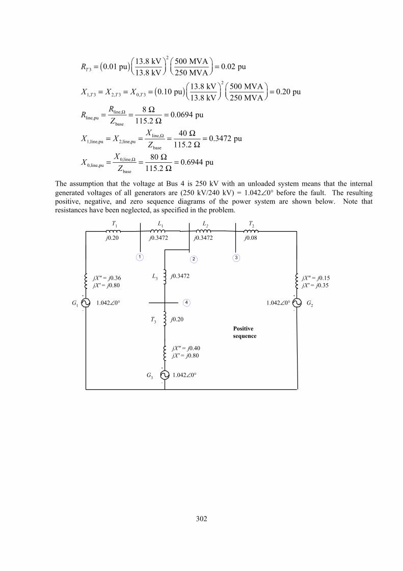
( )2
313.8 kV 500 MVA0.01 pu 0.02 pu13.8 kV 250 MVAT
R = =
( )2
1, 3 2, 3 0, 313.8 kV 500 MVA0.10 pu 0.20 pu13.8 kV 250 MVAT T TX = = = =
X X
line,line,pu
base
8 0.0694 pu115.2
RZ
Ω Ω= = =Ω
R
line,1,line,pu 2,line,pu
base
40 0.3472 pu115.2
XZ
Ω Ω= = = =Ω
X X
0,line,0,line,pu
base
80 0.6944 pu115.2
XZ
Ω Ω= = =Ω
X
The assumption that the voltage at Bus 4 is 250 kV with an unloaded system means that the internal generated voltages of all generators are (250 kV/240 kV) = 1.042∠0° before the fault. The resulting positive, negative, and zero sequence diagrams of the power system are shown below. Note that resistances have been neglected, as specified in the problem.
+
-
G1
jX" = j0.36jX' = j0.80
L1T1
j0.3472
T2
+
-
G2
jX" = j0.15jX' = j0.35
L3
+
-
G3
T3
L2
j0.3472
j0.3472
jX" = j0.40jX' = j0.80
j0.20 j0.08
1.042∠0°
1.042∠0°
1.042∠0°
1
4
32
j0.20Positivesequence
302
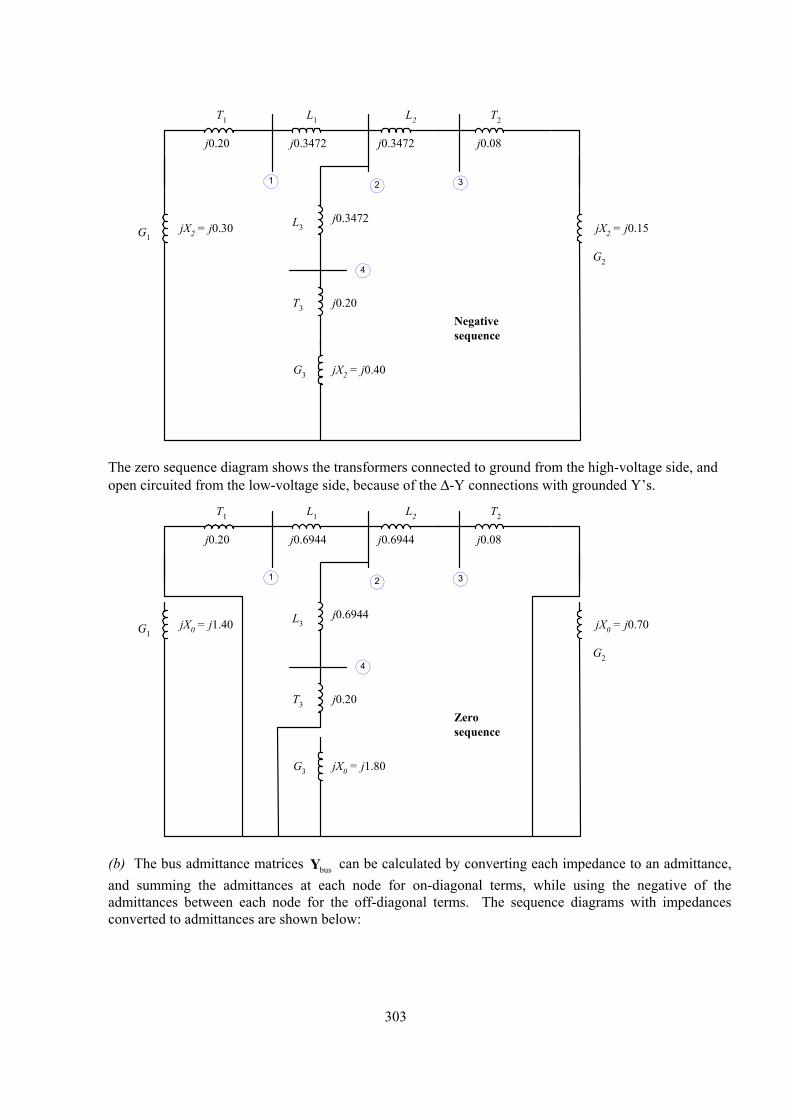
G1jX2 = j0.30
L1T1
j0.3472
T2
G2
L3
G3
T3
L2
j0.3472
j0.3472j0.20 j0.08
1
4
32
j0.20Negativesequence
jX2 = j0.15
jX2 = j0.40
The zero sequence diagram shows the transformers connected to ground from the high-voltage side, and
open circuited from the low-voltage side, because of the ∆-Y connections with grounded Y’s.
G1jX0 = j1.40
L1T1
j0.6944
T2
G2
L3
G3
T3
L2
j0.6944
j0.6944j0.20 j0.08
1
4
32
j0.20Zerosequence
jX0 = j0.70
jX0 = j1.80
(b) The bus admittance matrices busY can be calculated by converting each impedance to an admittance,
and summing the admittances at each node for on-diagonal terms, while using the negative of the admittances between each node for the off-diagonal terms. The sequence diagrams with impedances converted to admittances are shown below:
303
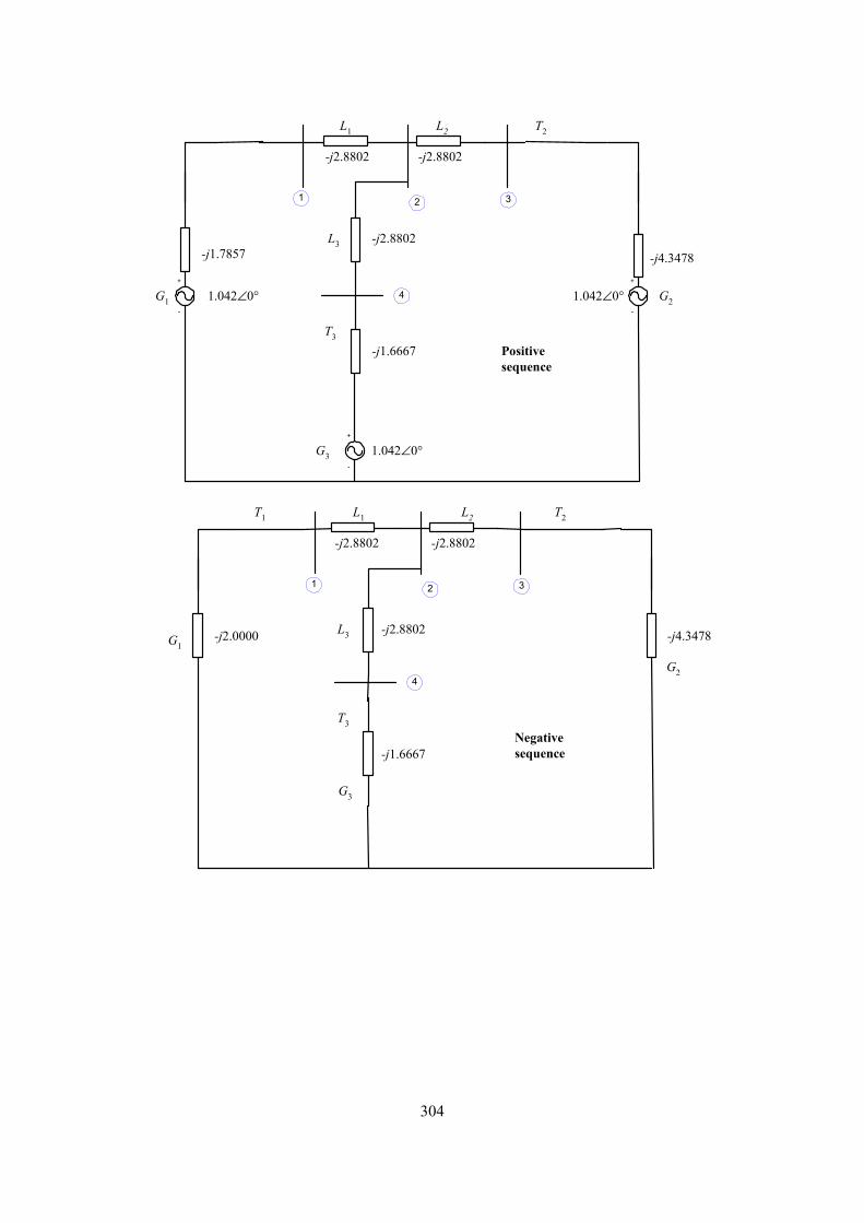
+
-
G1
-j1.7857
L1
-j2.8802
T2
+
-
G2
L3
+
-
G3
T3
L2
1.042∠0°
1.042∠0°
1.042∠0°
1
4
32
Positivesequence
-j4.3478
-j2.8802
-j2.8802
-j1.6667
G1
L1T1 T2
G2
L3
G3
T3
L2
1
4
32
-j1.6667Negativesequence
-j2.8802
-j2.8802-j2.8802
-j4.3478-j2.0000
304
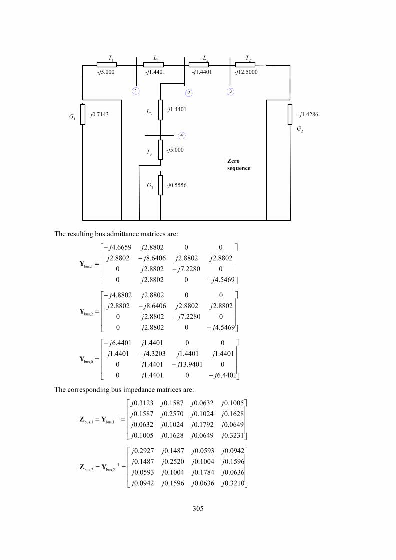
G1-j0.7143
L1T1 T2
G2
L3
G3
T3
L2
-j1.4401-j5.000 -j12.5000
1
4
32
Zerosequence
-j1.4286-j1.4401
-j1.4401
-j5.000
-j0.5556
The resulting bus admittance matrices are:
=Y bus,1
4.6659 2.8802 0 02.8802 8.6406 2.8802 2.8802
0 2.8802 7.2280 00 2.8802 0 4.5469
j jj j j j
j jj j
− − − −
=Y bus,2
4.8802 2.8802 0 02.8802 8.6406 2.8802 2.8802
0 2.8802 7.2280 00 2.8802 0 4.5469
j jj j j j
j jj j
− − − −
=Y bus,0
6.4401 1.4401 0 01.4401 4.3203 1.4401 1.4401
0 1.4401 13.9401 00 1.4401 0 6.4401
j jj j j j
j jj j
− − − −
The corresponding bus impedance matrices are:
1bus,1 bus,1
0.3123 0.1587 0.0632 0.10050.1587 0.2570 0.1024 0.16280.0632 0.1024 0.1792 0.06490.1005 0.1628 0.0649 0.3231
j j j jj j j jj j j jj j j j
−
= =
Z Y
Z Y 1bus,2 bus,2
0.2927 0.1487 0.0593 0.09420.1487 0.2520 0.1004 0.15960.0593 0.1004 0.1784 0.06360.0942 0.1596 0.0636 0.3210
j j j jj j j jj j j jj j j j
−
= =
305
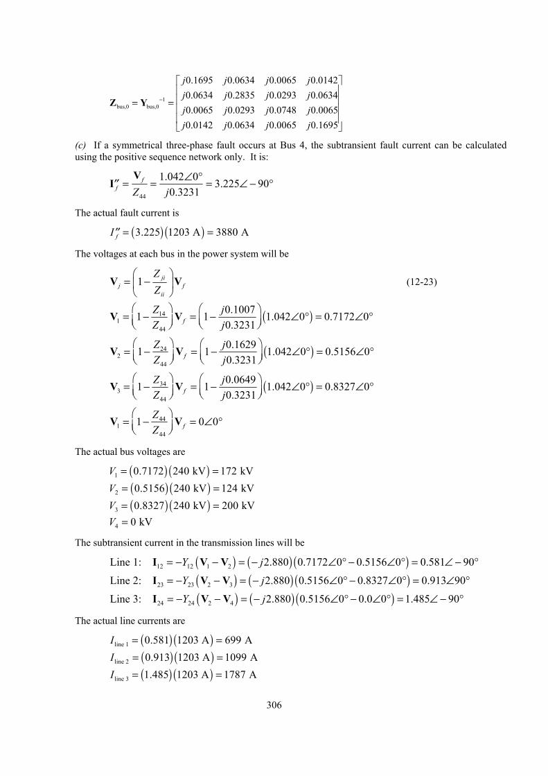
Z Y 1bus,0 bus,0
0.1695 0.0634 0.0065 0.01420.0634 0.2835 0.0293 0.06340.0065 0.0293 0.0748 0.00650.0142 0.0634 0.0065 0.1695
j j j jj j j jj j j jj j j j
−
= =
(c) If a symmetrical three-phase fault occurs at Bus 4, the subtransient fault current can be calculated using the positive sequence network only. It is:
44
1.042 0 3.225 900.3231
ff Z j
∠ ° = ∠ −′′V
= =I °
The actual fault current is
fI = =′′ ( ) ( )3.225 1203 A 3880 A
The voltages at each bus in the power system will be
1 jij
ii
ZZ
= −
fVV (12-23)
( )141
44
0.10071 1 1.042 0 0.7172 00.3231f
Z jZ j
= − = − ∠ ° = ∠
°V V
( )242
44
0.16291 1 1.042 0 0.5156 00.3231f
Z jZ j
= − = − ∠ ° = ∠
°V V
( )343
44
0.06491 1 1.042 0 0.8327 00.3231f
Z jZ j
= − = − ∠ ° = ∠
°V V
441
44
1 0fZZ
= − = ∠
0°V V
The actual bus voltages are
V = = ( ) ( )1 0.7172 240 kV 172 kV V = = ( ) ( )2 0.5156 240 kV 124 kV V = = ( ) ( )3 0.8327 240 kV 200 kV 0 kV = 4 V
The subtransient current in the transmission lines will be
L ( ) ( ) ( )12 12 1 2ine 1: 2.880 0.7172 0 0.5156 0 0.581 90Y j= − − = − ∠ ° − ∠ ° = ∠ − °I V V
L ( ) ( ) ( )23 23 2 3ine 2: 2.880 0.5156 0 0.8327 0 0.913 90Y j= − − = − ∠ ° − ∠ ° = ∠ °I V V
L ( ) ( ) ( )24 24 2 4ine 3: 2.880 0.5156 0 0.0 0 1.485 90Y j= − − = − ∠ ° − ∠ ° = ∠ − °I V V
The actual line currents are
I = = ( ) ( )line 1 0.581 1203 A 699 A I = = ( ) ( )line 2 0.913 1203 A 1099 A I = = ( ) ( )line 3 1.485 1203 A 1787 A
306
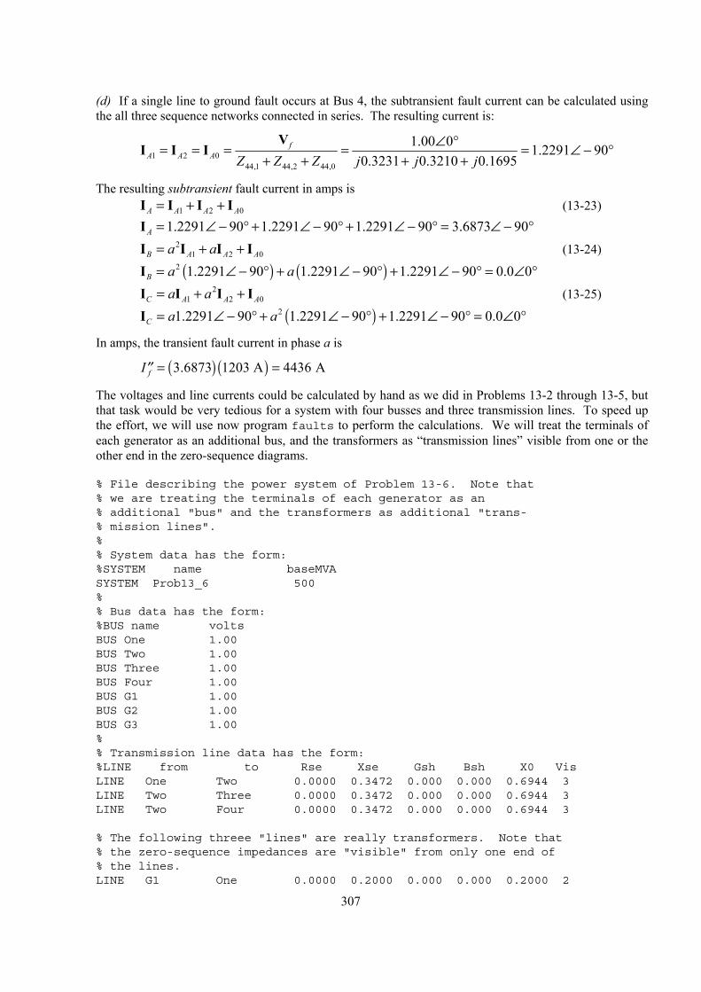
(d) If a single line to ground fault occurs at Bus 4, the subtransient fault current can be calculated using the all three sequence networks connected in series. The resulting current is:
1 2 044,1 44,2 44,0
1.00 0 1.2291 900.3231 0.3210 0.1695
fA A A Z Z Z j j j
∠ °= = = = = ∠ −+ + + +
VI °
0
I I
The resulting subtransient fault current in amps is 1 2A A A= + +I IA
0A
°
0A
°
I I (13-23) =I 1.2291 90 1.2291 90 1.2291 90 3.6873 90A ∠ − ° + ∠ − ° + ∠ − ° = ∠ − ° I I (13-24) 2
1 2B A Aa a= + +I I =I ( ) ( )2 1.2291 90 1.2291 90 1.2291 90 0.0 0B a a∠ − ° + ∠ − ° + ∠ − ° = ∠ I I (13-25) 2
1 2C A Aa a= + +I I =I ( )21.2291 90 1.2291 90 1.2291 90 0.0 0C a a∠ − ° + ∠ − ° + ∠ − ° = ∠
In amps, the transient fault current in phase a is
fI = =′′ ( ) ( )3.6873 1203 A 4436 A
The voltages and line currents could be calculated by hand as we did in Problems 13-2 through 13-5, but that task would be very tedious for a system with four busses and three transmission lines. To speed up the effort, we will use now program faults to perform the calculations. We will treat the terminals of each generator as an additional bus, and the transformers as “transmission lines” visible from one or the other end in the zero-sequence diagrams.
% File describing the power system of Problem 13-6. Note that% we are treating the terminals of each generator as an% additional "bus" and the transformers as additional "trans-% mission lines".%% System data has the form:%SYSTEM name baseMVASYSTEM Prob13_6 500%% Bus data has the form:%BUS name voltsBUS One 1.00BUS Two 1.00BUS Three 1.00BUS Four 1.00BUS G1 1.00BUS G2 1.00BUS G3 1.00%% Transmission line data has the form:%LINE from to Rse Xse Gsh Bsh X0 VisLINE One Two 0.0000 0.3472 0.000 0.000 0.6944 3LINE Two Three 0.0000 0.3472 0.000 0.000 0.6944 3LINE Two Four 0.0000 0.3472 0.000 0.000 0.6944 3
% The following threee "lines" are really transformers. Note that% the zero-sequence impedances are "visible" from only one end of% the lines.LINE G1 One 0.0000 0.2000 0.000 0.000 0.2000 2
307
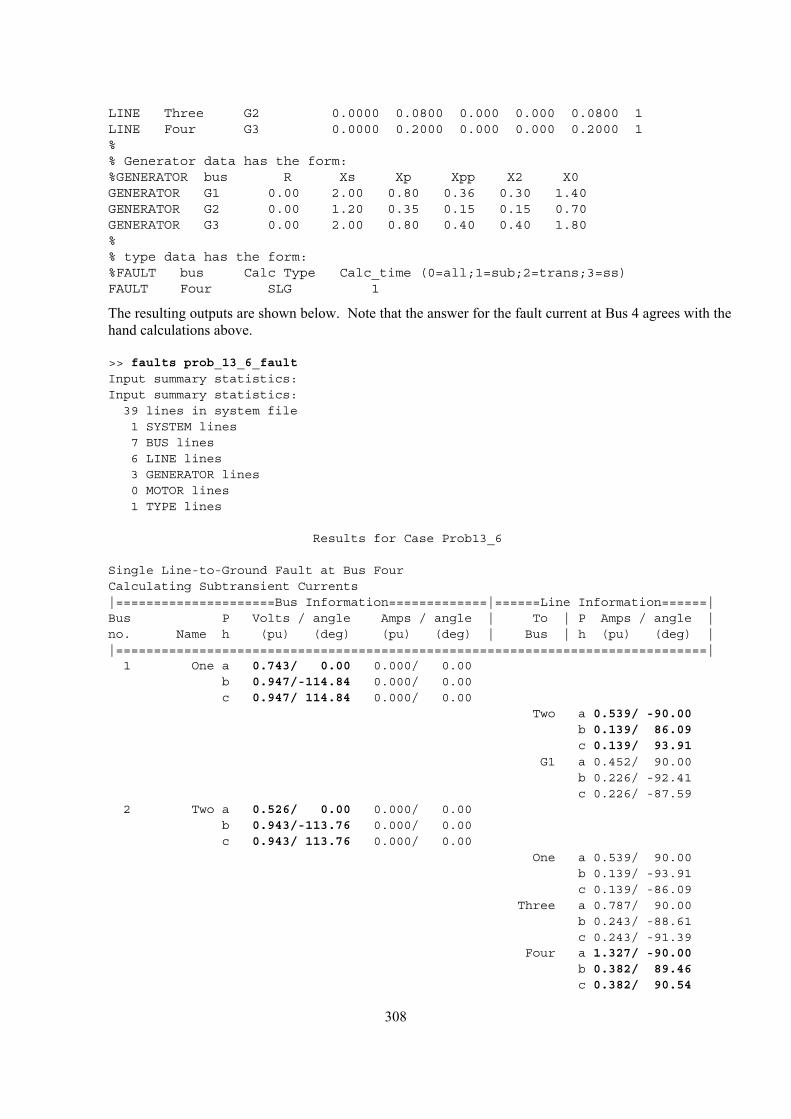
LINE Three G2 0.0000 0.0800 0.000 0.000 0.0800 1LINE Four G3 0.0000 0.2000 0.000 0.000 0.2000 1%% Generator data has the form:%GENERATOR bus R Xs Xp Xpp X2 X0GENERATOR G1 0.00 2.00 0.80 0.36 0.30 1.40GENERATOR G2 0.00 1.20 0.35 0.15 0.15 0.70GENERATOR G3 0.00 2.00 0.80 0.40 0.40 1.80%% type data has the form:%FAULT bus Calc Type Calc_time (0=all;1=sub;2=trans;3=ss)FAULT Four SLG 1
The resulting outputs are shown below. Note that the answer for the fault current at Bus 4 agrees with the hand calculations above.
>> faults prob_13_6_faultInput summary statistics:Input summary statistics:
39 lines in system file1 SYSTEM lines7 BUS lines6 LINE lines3 GENERATOR lines0 MOTOR lines1 TYPE lines
Results for Case Prob13_6
Single Line-to-Ground Fault at Bus FourCalculating Subtransient Currents|=====================Bus Information=============|======Line Information======|Bus P Volts / angle Amps / angle | To | P Amps / angle |no. Name h (pu) (deg) (pu) (deg) | Bus | h (pu) (deg) ||==============================================================================|
1 One a 0.743/ 0.00 0.000/ 0.00b 0.947/-114.84 0.000/ 0.00c 0.947/ 114.84 0.000/ 0.00
Two a 0.539/ -90.00b 0.139/ 86.09c 0.139/ 93.91
G1 a 0.452/ 90.00b 0.226/ -92.41c 0.226/ -87.59
2 Two a 0.526/ 0.00 0.000/ 0.00b 0.943/-113.76 0.000/ 0.00c 0.943/ 113.76 0.000/ 0.00
One a 0.539/ 90.00b 0.139/ -93.91c 0.139/ -86.09
Three a 0.787/ 90.00b 0.243/ -88.61c 0.243/ -91.39
Four a 1.327/ -90.00b 0.382/ 89.46c 0.382/ 90.54
308
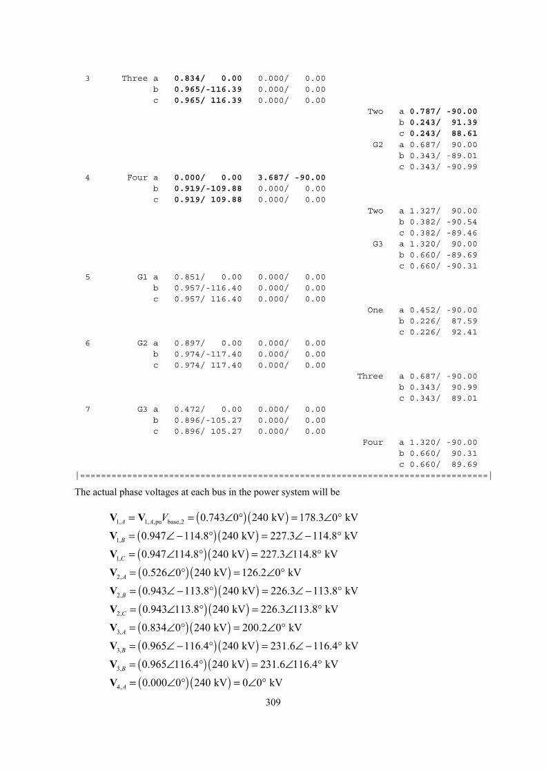
3 Three a 0.834/ 0.00 0.000/ 0.00b 0.965/-116.39 0.000/ 0.00c 0.965/ 116.39 0.000/ 0.00
Two a 0.787/ -90.00b 0.243/ 91.39c 0.243/ 88.61
G2 a 0.687/ 90.00b 0.343/ -89.01c 0.343/ -90.99
4 Four a 0.000/ 0.00 3.687/ -90.00b 0.919/-109.88 0.000/ 0.00c 0.919/ 109.88 0.000/ 0.00
Two a 1.327/ 90.00b 0.382/ -90.54c 0.382/ -89.46
G3 a 1.320/ 90.00b 0.660/ -89.69c 0.660/ -90.31
5 G1 a 0.851/ 0.00 0.000/ 0.00b 0.957/-116.40 0.000/ 0.00c 0.957/ 116.40 0.000/ 0.00
One a 0.452/ -90.00b 0.226/ 87.59c 0.226/ 92.41
6 G2 a 0.897/ 0.00 0.000/ 0.00b 0.974/-117.40 0.000/ 0.00c 0.974/ 117.40 0.000/ 0.00
Three a 0.687/ -90.00b 0.343/ 90.99c 0.343/ 89.01
7 G3 a 0.472/ 0.00 0.000/ 0.00b 0.896/-105.27 0.000/ 0.00c 0.896/ 105.27 0.000/ 0.00
Four a 1.320/ -90.00b 0.660/ 90.31c 0.660/ 89.69
|==============================================================================|
The actual phase voltages at each bus in the power system will be V V ( ) ( )1, 1, ,pu base,2 0.743 0 240 kV 178.3 0 kVA A V= = ∠ ° = ∠ °
= ∠V ( ) ( )1, 0.947 114.8 240 kV 227.3 114.8 kVB − ° = ∠ − °
= ∠V ( ) ( )1, 0.947 114.8 240 kV 227.3 114.8 kVC ° = ∠ °
= ∠V ( ) ( )2, 0.526 0 240 kV 126.2 0 kVA ° = ∠ °
=V ( ) ( )2, 0.943 113.8 240 kV 226.3 113.8 kVB ∠ − ° = ∠ − °
= ∠V ( ) ( )2, 0.943 113.8 240 kV 226.3 113.8 kVC ° = ∠ °
= ∠V ( ) ( )3, 0.834 0 240 kV 200.2 0 kVA ° = ∠ °
= ∠V ( ) ( )3, 0.965 116.4 240 kV 231.6 116.4 kVB − ° = ∠ − °
= ∠V ( ) ( )3, 0.965 116.4 240 kV 231.6 116.4 kVB ° = ∠ °
= ∠V ( ) ( )4, 0.000 0 240 kV 0 0 kVA ° = ∠ °
309
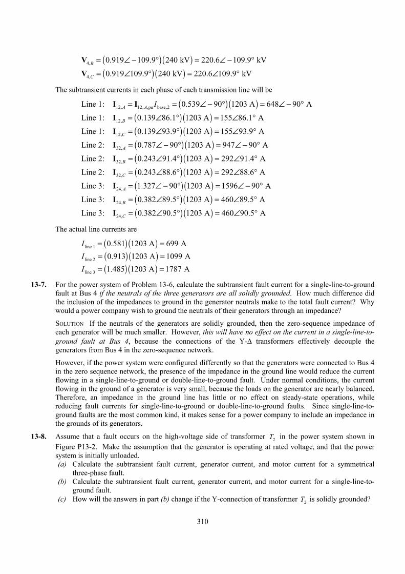
=V ( ) ( )4, 0.919 109.9 240 kV 220.6 109.9 kVB ∠ − ° = ∠ − °
= ∠V ( ) ( )4, 0.919 109.9 240 kV 220.6 109.9 kVC ° = ∠ °
The subtransient currents in each phase of each transmission line will be
L ( ) ( )12, 12, ,pu base,2ine 1: 0.539 90 1203 A 648 90 AA A I= = ∠ − ° = ∠ − °I I
L ( ) ( )12,ine 1: 0.139 86.1 1203 A 155 86.1 AB = ∠ ° = ∠ °I
L ( ) ( )12,ine 1: 0.139 93.9 1203 A 155 93.9 AC = ∠ ° = ∠ °I
L ( ) ( )32,ine 2: 0.787 90 1203 A 947 90 AA = ∠ − ° = ∠ − °I
L ( ) ( )32,ine 2: 0.243 91.4 1203 A 292 91.4 AB = ∠ ° = ∠ °I
L ( ) ( )32,ine 2: 0.243 88.6 1203 A 292 88.6 AC = ∠ ° = ∠ °I
L ( ) ( )24,ine 3: 1.327 90 1203 A 1596 90 AA = ∠ − ° = ∠ − °I
L ( ) ( )24,ine 3: 0.382 89.5 1203 A 460 89.5 AB = ∠ ° = ∠ °I
L ( ) ( )24,ine 3: 0.382 90.5 1203 A 460 90.5 AC = ∠ ° = ∠ °I
The actual line currents are
I = = ( ) ( )line 1 0.581 1203 A 699 A I = = ( ) ( )line 2 0.913 1203 A 1099 A I = = ( ) ( )line 3 1.485 1203 A 1787 A
13-7. For the power system of Problem 13-6, calculate the subtransient fault current for a single-line-to-ground fault at Bus 4 if the neutrals of the three generators are all solidly grounded. How much difference did the inclusion of the impedances to ground in the generator neutrals make to the total fault current? Why would a power company wish to ground the neutrals of their generators through an impedance?
SOLUTION If the neutrals of the generators are solidly grounded, then the zero-sequence impedance of each generator will be much smaller. However, this will have no effect on the current in a single-line-to-ground fault at Bus 4, because the connections of the Y-∆ transformers effectively decouple the generators from Bus 4 in the zero-sequence network.
However, if the power system were configured differently so that the generators were connected to Bus 4 in the zero sequence network, the presence of the impedance in the ground line would reduce the current flowing in a single-line-to-ground or double-line-to-ground fault. Under normal conditions, the current flowing in the ground of a generator is very small, because the loads on the generator are nearly balanced. Therefore, an impedance in the ground line has little or no effect on steady-state operations, while reducing fault currents for single-line-to-ground or double-line-to-ground faults. Since single-line-to-ground faults are the most common kind, it makes sense for a power company to include an impedance in the grounds of its generators.
13-8. Assume that a fault occurs on the high-voltage side of transformer in the power system shown in Figure P13-2. Make the assumption that the generator is operating at rated voltage, and that the power system is initially unloaded.
2T
(a) Calculate the subtransient fault current, generator current, and motor current for a symmetrical three-phase fault.
(b) Calculate the subtransient fault current, generator current, and motor current for a single-line-to-ground fault.
(c) How will the answers in part (b) change if the Y-connection of transformer T is solidly grounded? 2
310
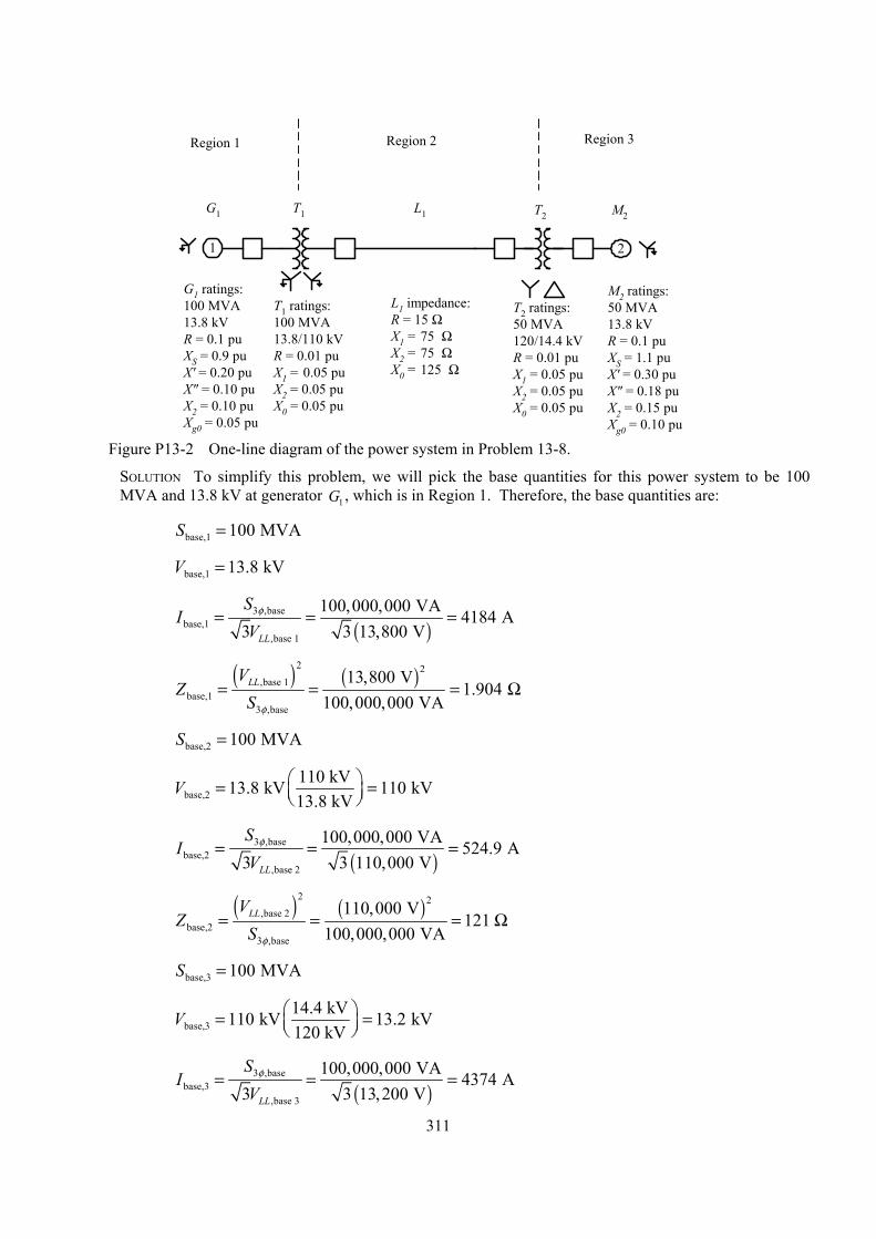
1 2
G1 ratings:100 MVA13.8 kVR = 0.1 puXS = 0.9 puX' = 0.20 puX" = 0.10 puX2 = 0.10 puXg0 = 0.05 pu
T1 ratings:100 MVA13.8/110 kVR = 0.01 puX1 = 0.05 puX2 = 0.05 puX0 = 0.05 pu
G1 T1 T2 M2
T2 ratings:50 MVA120/14.4 kVR = 0.01 puX1 = 0.05 puX2 = 0.05 puX0 = 0.05 pu
M2 ratings:50 MVA13.8 kVR = 0.1 puXS = 1.1 puX' = 0.30 puX" = 0.18 puX2 = 0.15 puXg0 = 0.10 pu
L1 impedance:R = 15 ΩX1 = 75 ΩX2 = 75 ΩX0 = 125 Ω
L1
Region 1 Region 2 Region 3
Figure P13-2 One-line diagram of the power system in Problem 13-8.
SOLUTION To simplify this problem, we will pick the base quantities for this power system to be 100 MVA and 13.8 kV at generator G , which is in Region 1. Therefore, the base quantities are: 1
S base,1 100 MVA=
V base,1 13.8 kV=
( )
3 ,basebase,1
,base 1
100,000,000 VA 4184 A3 3 13,800 VLL
SV
φ= = =I
( ) ( )
2 2,base 1
base,13 ,base
13,800 V1.904
100,000,000 VALLVS φ
= = =Z Ω
S base,2 100 MVA=
base,2110 kV13.8 kV 110 kV13.8 kV = =
V
( )
3 ,basebase,2
,base 2
100,000,000 VA 524.9 A3 3 110,000 VLL
SV
φ= = =I
( ) ( )
2 2,base 2
base,23 ,base
110,000 V121
100,000,000 VALLVS φ
= = =Z Ω
S base,3 100 MVA=
base,314.4 kV110 kV 13.2 kV120 kV
= = V
( )
3 ,basebase,3
,base 3
100,000,000 VA 4374 A3 3 13,200 VLL
SV
φ= = =I
311
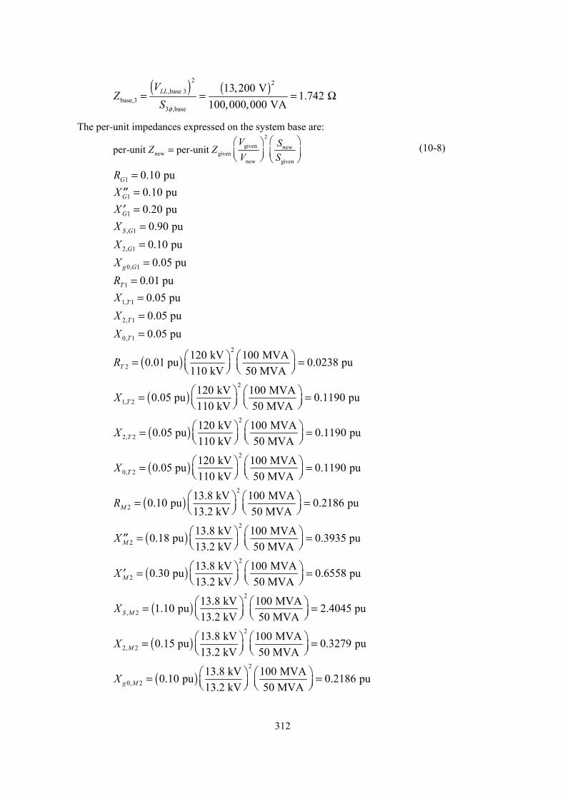
( ) ( )
2 2,base 3
base,33 ,base
13,200 V1.742
100,000,000 VALLVS φ
= = =Z Ω
The per-unit impedances expressed on the system base are:
2
given newnew given
new given
r-unit per-unit V SZ ZV S
=
pe (10-8)
R = 1 0.10 puG
X = 1 0.10 puG′′ X = 1 0.20 puG′ X , 1 0.90 puS G = X 2, 1 0.10 puG = g GX 0, 1 0.05 pu= R = 1 0.01 puT
X 1, 1 0.05 puT = X 2, 1 0.05 puT = X 0, 1 0.05 puT =
( )2
2120 kV 100 MVA0.01 pu 0.0238 pu110 kV 50 MVAT
R = =
( )2
1,120 kV 100 MVA0.05 pu 0.1190 pu110 kV 50 MVAT = = 2X
( )2
2,120 kV 100 MVA0.05 pu 0.1190 pu110 kV 50 MVAT = = 2X
( )2
0,120 kV 100 MVA0.05 pu 0.1190 pu110 kV 50 MVAT = = 2X
( )213.8 kV 100 MVA0.10 pu 0.2186 pu
13.2 kV 50 MVAM 2R = =
( )213.8 kV 100 MVA0.18 pu 0.3935 pu
13.2 kV 50 MVAM 2X = =′′
( )213.8 kV 100 MVA0.30 pu 0.6558 pu
13.2 kV 50 MVAM 2X = =′
( )2
, 213.8 kV 100 MVA1.10 pu 2.4045 pu13.2 kV 50 MVAS M = =
X
( )2
2, 213.8 kV 100 MVA0.15 pu 0.3279 pu13.2 kV 50 MVAM = =
X
( )2
0, 213.8 kV 100 MVA0.10 pu 0.2186 pu13.2 kV 50 MVA = = g MX
312
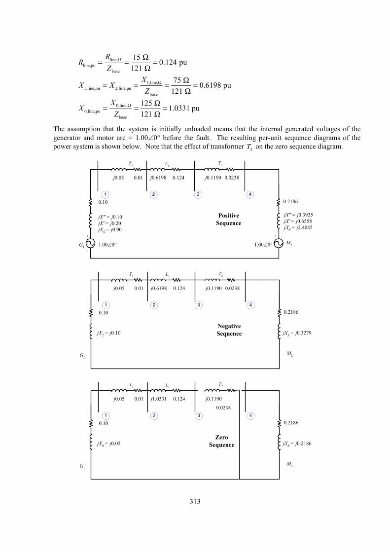
line,line,pu
base
15 0.124 pu121
RZ
Ω Ω= = =Ω
R
1,line,1,line,pu 2,line,pu
base
75 0.6198 pu121
XZ
Ω Ω= = = =Ω
X X
0,line,0,line,pu
base
125 1.0331 pu121
XZ
Ω Ω= = =Ω
X
The assumption that the system is initially unloaded means that the internal generated voltages of the generator and motor are = 1.00∠0° before the fault. The resulting per-unit sequence diagrams of the power system is shown below. Note that the effect of transformer T on the zero sequence diagram. 2
+
-
G1
0.10
jX" = j0.10jX' = j0.20jXS = j0.90
L1T1
j0.1190
+
-
M2
0.2186
jX" = j0.3935jX' = j0.6558jXS = j2.4045
T2
j0.6198 0.02380.1240.01j0.05
1.00∠0° 1.00∠0°
1 32 4
PositiveSequence
G1
0.10
jX2 = j0.10
L1T1
j0.1190
M2
0.2186
jXS = j0.3279
T2
j0.6198 0.02380.1240.01j0.05
1 32 4
NegativeSequence
G1
0.10
jX0 = j0.05
L1T1
j0.1190
M2
0.2186
jXS = j0.2186
T2
j1.0331
0.0238
0.1240.01j0.05
1 32 4
ZeroSequence
313
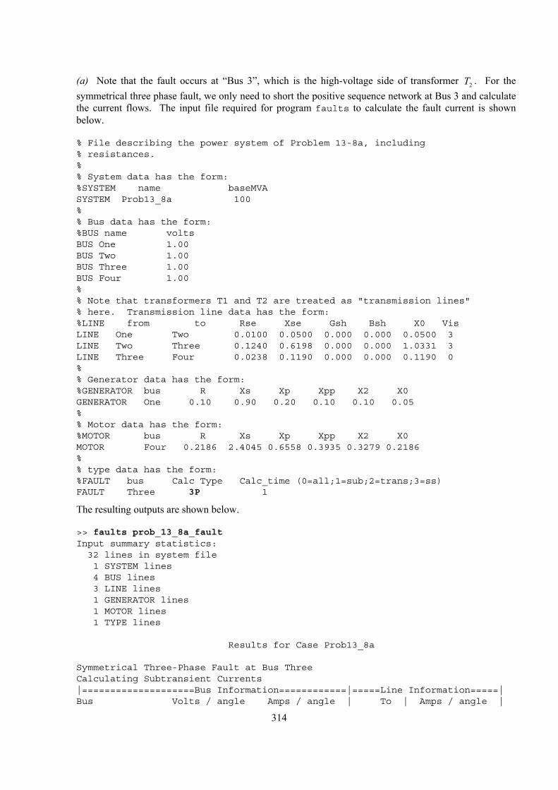
(a) Note that the fault occurs at “Bus 3”, which is the high-voltage side of transformer T . For the symmetrical three phase fault, we only need to short the positive sequence network at Bus 3 and calculate the current flows. The input file required for program faults to calculate the fault current is shown below.
2
% File describing the power system of Problem 13-8a, including% resistances.%% System data has the form:%SYSTEM name baseMVASYSTEM Prob13_8a 100%% Bus data has the form:%BUS name voltsBUS One 1.00BUS Two 1.00BUS Three 1.00BUS Four 1.00%% Note that transformers T1 and T2 are treated as "transmission lines"% here. Transmission line data has the form:%LINE from to Rse Xse Gsh Bsh X0 VisLINE One Two 0.0100 0.0500 0.000 0.000 0.0500 3LINE Two Three 0.1240 0.6198 0.000 0.000 1.0331 3LINE Three Four 0.0238 0.1190 0.000 0.000 0.1190 0%% Generator data has the form:%GENERATOR bus R Xs Xp Xpp X2 X0GENERATOR One 0.10 0.90 0.20 0.10 0.10 0.05%% Motor data has the form:%MOTOR bus R Xs Xp Xpp X2 X0MOTOR Four 0.2186 2.4045 0.6558 0.3935 0.3279 0.2186%% type data has the form:%FAULT bus Calc Type Calc_time (0=all;1=sub;2=trans;3=ss)FAULT Three 3P 1
The resulting outputs are shown below.
>> faults prob_13_8a_faultInput summary statistics:32 lines in system file1 SYSTEM lines4 BUS lines3 LINE lines1 GENERATOR lines1 MOTOR lines1 TYPE lines
Results for Case Prob13_8a
Symmetrical Three-Phase Fault at Bus ThreeCalculating Subtransient Currents|====================Bus Information============|=====Line Information=====|Bus Volts / angle Amps / angle | To | Amps / angle |
314
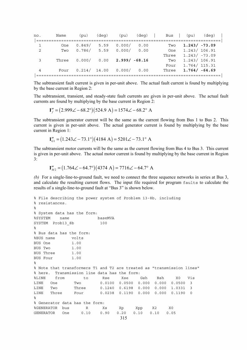
no. Name (pu) (deg) (pu) (deg) | Bus | (pu) (deg) ||==========================================================================|1 One 0.849/ 5.59 0.000/ 0.00 Two 1.243/ -73.092 Two 0.786/ 5.59 0.000/ 0.00 One 1.243/ 106.91
Three 1.243/ -73.093 Three 0.000/ 0.00 2.999/ -68.16 Two 1.243/ 106.91
Four 1.764/ 115.314 Four 0.214/ 14.00 0.000/ 0.00 Three 1.764/ -64.69
|==========================================================================|
The subtransient fault current is given in per-unit above. The actual fault current is found by multiplying by the base current in Region 2:
The subtransient, transient, and steady-state fault currents are given in per-unit above. The actual fault currents are found by multiplying by the base current in Region 2:
=I ( ) ( )2.999 68.2 524.9 A 1574 68.2 Af ∠ − ° = ∠ − °′′
The subtransient generator current will be the same as the current flowing from Bus 1 to Bus 2. This current is given in per-unit above. The actual generator current is found by multiplying by the base current in Region 1:
=I ( ) ( )1 1.243 73.1 4184 A 5201 73.1 AG ∠ − ° = ∠ − °′′
The subtransient motor currents will be the same as the current flowing from Bus 4 to Bus 3. This current is given in per-unit above. The actual motor current is found by multiplying by the base current in Region 3:
=I ( ) ( )2 1.764 64.7 4374 A 7716 64.7 AM ∠ − ° = ∠ − °′′
(b) For a single-line-to-ground fault, we need to connect the three sequence networks in series at Bus 3, and calculate the resulting current flows. The input file required for program faults to calculate the results of a single-line-to-ground fault at “Bus 3” is shown below.
% File describing the power system of Problem 13-8b, including% resistances.%% System data has the form:%SYSTEM name baseMVASYSTEM Prob13_8b 100%% Bus data has the form:%BUS name voltsBUS One 1.00BUS Two 1.00BUS Three 1.00BUS Four 1.00%% Note that transformers T1 and T2 are treated as "transmission lines"% here. Transmission line data has the form:%LINE from to Rse Xse Gsh Bsh X0 VisLINE One Two 0.0100 0.0500 0.000 0.000 0.0500 3LINE Two Three 0.1240 0.6198 0.000 0.000 1.0331 3LINE Three Four 0.0238 0.1190 0.000 0.000 0.1190 0%% Generator data has the form:%GENERATOR bus R Xs Xp Xpp X2 X0
315 GENERATOR One 0.10 0.90 0.20 0.10 0.10 0.05
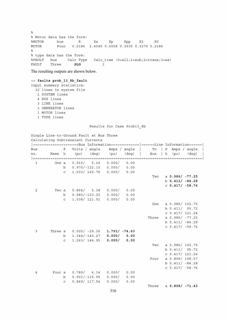
%% Motor data has the form:%MOTOR bus R Xs Xp Xpp X2 X0MOTOR Four 0.2186 2.4045 0.6558 0.3935 0.3279 0.2186%% type data has the form:%FAULT bus Calc Type Calc_time (0=all;1=sub;2=trans;3=ss)FAULT Three SLG 1
The resulting outputs are shown below.
>> faults prob_13_8b_faultInput summary statistics:
32 lines in system file1 SYSTEM lines4 BUS lines3 LINE lines1 GENERATOR lines1 MOTOR lines1 TYPE lines
Results for Case Prob13_8b
Single Line-to-Ground Fault at Bus ThreeCalculating Subtransient Currents|=====================Bus Information=============|======Line Information======|Bus P Volts / angle Amps / angle | To | P Amps / angle |no. Name h (pu) (deg) (pu) (deg) | Bus | h (pu) (deg) ||==============================================================================|
1 One a 0.915/ 5.16 0.000/ 0.00b 0.970/-122.15 0.000/ 0.00c 1.033/ 120.76 0.000/ 0.00
Two a 0.986/ -77.25b 0.411/ -84.28c 0.417/ -58.76
2 Two a 0.864/ 5.38 0.000/ 0.00b 0.980/-123.25 0.000/ 0.00c 1.038/ 121.91 0.000/ 0.00
One a 0.986/ 102.75b 0.411/ 95.72c 0.417/ 121.24
Three a 0.986/ -77.25b 0.411/ -84.28c 0.417/ -58.76
3 Three a 0.000/ -29.36 1.791/ -74.63b 1.344/-140.27 0.000/ 0.00c 1.263/ 144.95 0.000/ 0.00
Two a 0.986/ 102.75b 0.411/ 95.72c 0.417/ 121.24
Four a 0.808/ 108.57b 0.411/ -84.28c 0.417/ -58.76
4 Four a 0.789/ 4.14 0.000/ 0.00b 0.901/-115.95 0.000/ 0.00c 0.849/ 117.54 0.000/ 0.00
Three a 0.808/ -71.43
316
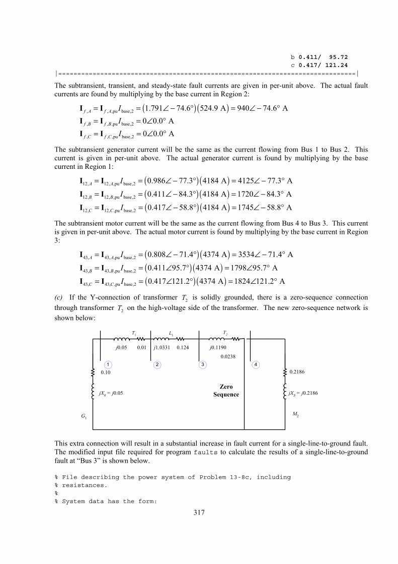
b 0.411/ 95.72c 0.417/ 121.24
|==============================================================================|
The subtransient, transient, and steady-state fault currents are given in per-unit above. The actual fault currents are found by multiplying by the base current in Region 2:
I I ( ) ( ), , ,pu base,2 1.791 74.6 524.9 A 940 74.6 Af A f A I= = ∠ − ° = ∠ − ° I I , , ,pu base,2 0 0.0 Af B f B I= = ∠ °
°
°
°
°
°
°
I I , , ,pu base,2 0 0.0 Af C f C I= = ∠
The subtransient generator current will be the same as the current flowing from Bus 1 to Bus 2. This current is given in per-unit above. The actual generator current is found by multiplying by the base current in Region 1:
I I ( ) ( )12, 12, ,pu base,2 0.986 77.3 4184 A 4125 77.3 AA A I= = ∠ − ° = ∠ −
I I ( ) ( )12, 12, ,pu base,2 0.411 84.3 4184 A 1720 84.3 AB B I= = ∠ − ° = ∠ −
I I ( ) ( )12, 12, ,pu base,2 0.417 58.8 4184 A 1745 58.8 AC C I= = ∠ − ° = ∠ − °
The subtransient motor current will be the same as the current flowing from Bus 4 to Bus 3. This current is given in per-unit above. The actual motor current is found by multiplying by the base current in Region 3:
I I ( ) ( )43, 43, ,pu base,2 0.808 71.4 4374 A 3534 71.4 AA A I= = ∠ − ° = ∠ −
I I ( ) ( )43, 43, ,pu base,2 0.411 95.7 4374 A 1798 95.7 AB B I= = ∠ ° = ∠
I I ( ) ( )43, 43, ,pu base,2 0.417 121.2 4374 A 1824 121.2 AC C I= = ∠ ° = ∠
(c) If the Y-connection of transformer T is solidly grounded, there is a zero-sequence connection through transformer T on the high-voltage side of the transformer. The new zero-sequence network is shown below:
2
2
G1
0.10
jX0 = j0.05
L1T1
j0.1190
M2
0.2186
jXS = j0.2186
T2
j1.0331
0.0238
0.1240.01j0.05
1 32 4
ZeroSequence
This extra connection will result in a substantial increase in fault current for a single-line-to-ground fault.
The modified input file required for program faults to calculate the results of a single-line-to-ground fault at “Bus 3” is shown below.
% File describing the power system of Problem 13-8c, including% resistances.%% System data has the form:
317
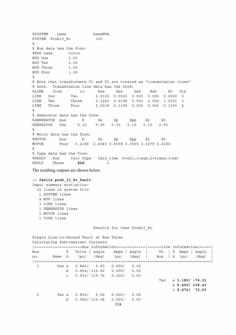
%SYSTEM name baseMVASYSTEM Prob13_8c 100%% Bus data has the form:%BUS name voltsBUS One 1.00BUS Two 1.00BUS Three 1.00BUS Four 1.00%% Note that transformers T1 and T2 are treated as "transmission lines"% here. Transmission line data has the form:%LINE from to Rse Xse Gsh Bsh X0 VisLINE One Two 0.0100 0.0500 0.000 0.000 0.0500 3LINE Two Three 0.1240 0.6198 0.000 0.000 1.0331 3LINE Three Four 0.0238 0.1190 0.000 0.000 0.1190 1%% Generator data has the form:%GENERATOR bus R Xs Xp Xpp X2 X0GENERATOR One 0.10 0.90 0.20 0.10 0.10 0.05%% Motor data has the form:%MOTOR bus R Xs Xp Xpp X2 X0MOTOR Four 0.2186 2.4045 0.6558 0.3935 0.3279 0.2186%% type data has the form:%FAULT bus Calc Type Calc_time (0=all;1=sub;2=trans;3=ss)FAULT Three SLG 1
The resulting outputs are shown below.
>> faults prob_13_8c_faultInput summary statistics:
32 lines in system file1 SYSTEM lines4 BUS lines3 LINE lines1 GENERATOR lines1 MOTOR lines1 TYPE lines
Results for Case Prob13_8c
Single Line-to-Ground Fault at Bus ThreeCalculating Subtransient Currents|=====================Bus Information=============|======Line Information======|Bus P Volts / angle Amps / angle | To | P Amps / angle |no. Name h (pu) (deg) (pu) (deg) | Bus | h (pu) (deg) ||==============================================================================|
1 One a 0.866/ 5.60 0.000/ 0.00b 0.964/-116.92 0.000/ 0.00c 0.932/ 119.76 0.000/ 0.00
Two a 1.180/ -74.31b 0.400/ 138.43c 0.476/ 72.03
2 Two a 0.805/ 5.69 0.000/ 0.00
318 b 0.946/-116.38 0.000/ 0.00
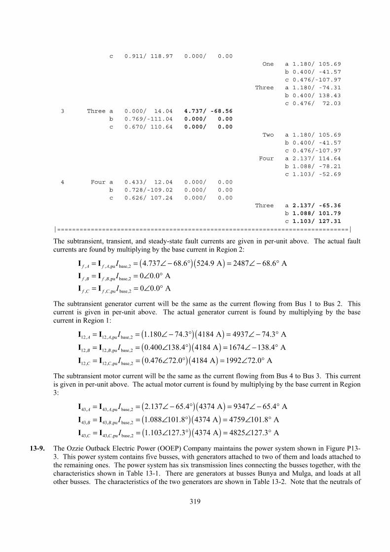
c 0.911/ 118.97 0.000/ 0.00One a 1.180/ 105.69
b 0.400/ -41.57c 0.476/-107.97
Three a 1.180/ -74.31b 0.400/ 138.43c 0.476/ 72.03
3 Three a 0.000/ 14.04 4.737/ -68.56b 0.769/-111.04 0.000/ 0.00c 0.670/ 110.64 0.000/ 0.00
Two a 1.180/ 105.69b 0.400/ -41.57c 0.476/-107.97
Four a 2.137/ 114.64b 1.088/ -78.21c 1.103/ -52.69
4 Four a 0.433/ 12.04 0.000/ 0.00b 0.728/-109.02 0.000/ 0.00c 0.626/ 107.24 0.000/ 0.00
Three a 2.137/ -65.36b 1.088/ 101.79c 1.103/ 127.31
|==============================================================================|
The subtransient, transient, and steady-state fault currents are given in per-unit above. The actual fault currents are found by multiplying by the base current in Region 2:
I I ( ) ( ), , ,pu base,2 4.737 68.6 524.9 A 2487 68.6 Af A f A I= = ∠ − ° = ∠ − °°°
°
°
°
°
°
I I , , ,pu base,2 0 0.0 Af B f B I= = ∠ I I , , ,pu base,2 0 0.0 Af C f C I= = ∠
The subtransient generator current will be the same as the current flowing from Bus 1 to Bus 2. This current is given in per-unit above. The actual generator current is found by multiplying by the base current in Region 1:
I I ( ) ( )12, 12, ,pu base,2 1.180 74.3 4184 A 4937 74.3 AA A I= = ∠ − ° = ∠ − °
I I ( ) ( )12, 12, ,pu base,2 0.400 138.4 4184 A 1674 138.4 AB B I= = ∠ ° = ∠ −
I I ( ) ( )12, 12, ,pu base,2 0.476 72.0 4184 A 1992 72.0 AC C I= = ∠ ° = ∠
The subtransient motor current will be the same as the current flowing from Bus 4 to Bus 3. This current is given in per-unit above. The actual motor current is found by multiplying by the base current in Region 3:
I I ( ) ( )43, 43, ,pu base,2 2.137 65.4 4374 A 9347 65.4 AA A I= = ∠ − ° = ∠ −
I I ( ) ( )43, 43, ,pu base,2 1.088 101.8 4374 A 4759 101.8 AB B I= = ∠ ° = ∠
I I ( ) ( )43, 43, ,pu base,2 1.103 127.3 4374 A 4825 127.3 AC C I= = ∠ ° = ∠
13-9. The Ozzie Outback Electric Power (OOEP) Company maintains the power system shown in Figure P13-3. This power system contains five busses, with generators attached to two of them and loads attached to the remaining ones. The power system has six transmission lines connecting the busses together, with the characteristics shown in Table 13-1. There are generators at busses Bunya and Mulga, and loads at all other busses. The characteristics of the two generators are shown in Table 13-2. Note that the neutrals of
319
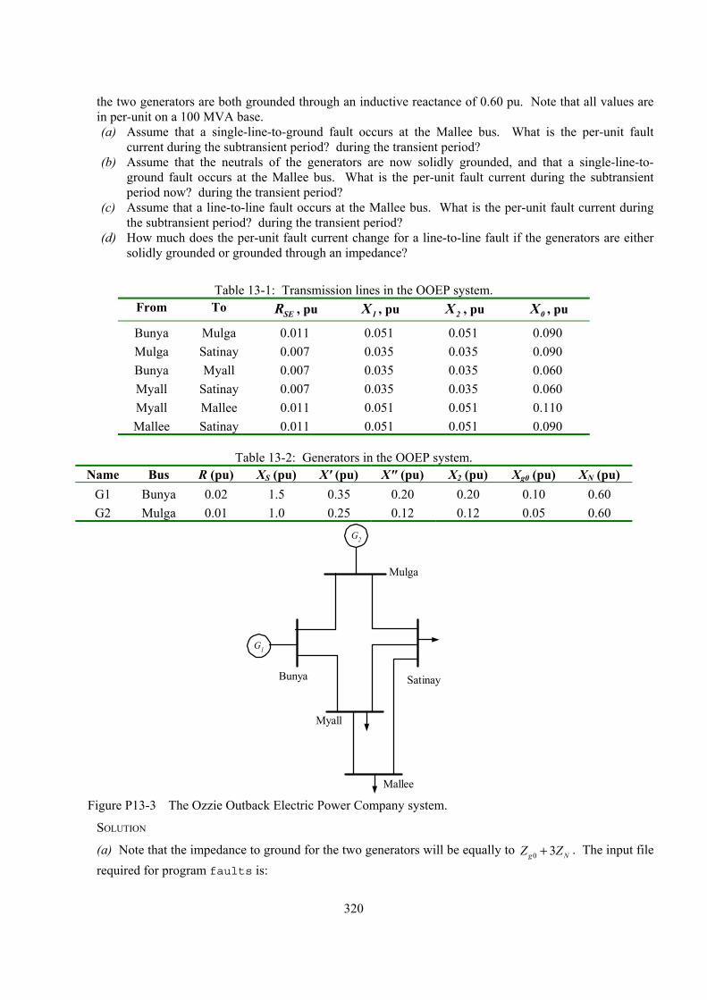
the two generators are both grounded through an inductive reactance of 0.60 pu. Note that all values are in per-unit on a 100 MVA base. (a) Assume that a single-line-to-ground fault occurs at the Mallee bus. What is the per-unit fault
current during the subtransient period? during the transient period? (b) Assume that the neutrals of the generators are now solidly grounded, and that a single-line-to-
ground fault occurs at the Mallee bus. What is the per-unit fault current during the subtransient period now? during the transient period?
(c) Assume that a line-to-line fault occurs at the Mallee bus. What is the per-unit fault current during the subtransient period? during the transient period?
(d) How much does the per-unit fault current change for a line-to-line fault if the generators are either solidly grounded or grounded through an impedance?
Table 13-1: Transmission lines in the OOEP system.
From To SER , pu 1X , pu 2X , pu 0X , pu
Bunya Mulga 0.011 0.051 0.051 0.090 Mulga Satinay 0.007 0.035 0.035 0.090 Bunya Myall 0.007 0.035 0.035 0.060 Myall Satinay 0.007 0.035 0.035 0.060 Myall Mallee 0.011 0.051 0.051 0.110 Mallee Satinay 0.011 0.051 0.051 0.090
Table 13-2: Generators in the OOEP system. Name Bus R (pu) XS (pu) X' (pu) X" (pu) X2 (pu) Xg0 (pu) XN (pu)
G1 Bunya 0.02 1.5 0.35 0.20 0.20 0.10 0.60 G2 Mulga 0.01 1.0 0.25 0.12 0.12 0.05 0.60
G1
G2
Bunya Satinay
Mulga
Mallee
Myall
Figure P13-3 The Ozzie Outback Electric Power Company system.
SOLUTION
(a) Note that the impedance to ground for the two generators will be equally to 0 3g NZ Z+ . The input file required for program faults is:
320
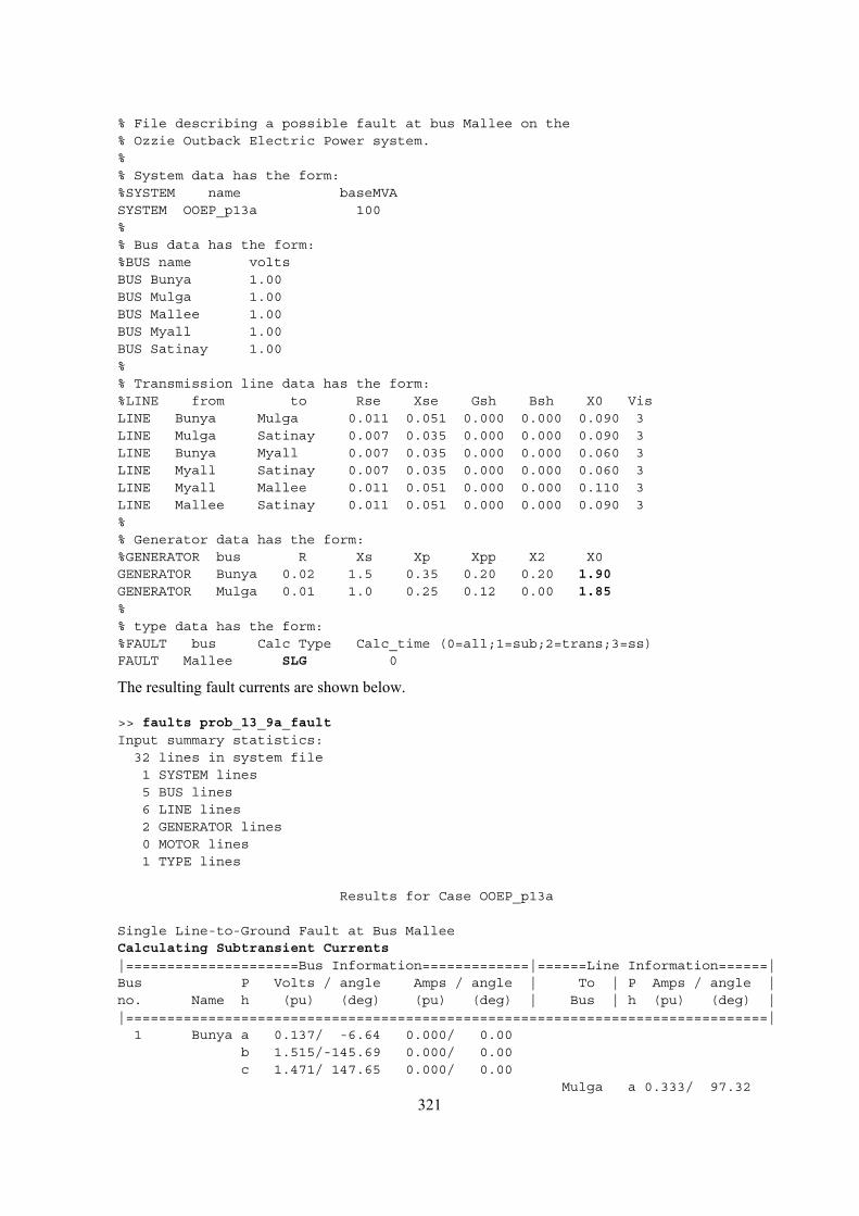
% File describing a possible fault at bus Mallee on the% Ozzie Outback Electric Power system.%% System data has the form:%SYSTEM name baseMVASYSTEM OOEP_p13a 100%% Bus data has the form:%BUS name voltsBUS Bunya 1.00BUS Mulga 1.00BUS Mallee 1.00BUS Myall 1.00BUS Satinay 1.00%% Transmission line data has the form:%LINE from to Rse Xse Gsh Bsh X0 VisLINE Bunya Mulga 0.011 0.051 0.000 0.000 0.090 3LINE Mulga Satinay 0.007 0.035 0.000 0.000 0.090 3LINE Bunya Myall 0.007 0.035 0.000 0.000 0.060 3LINE Myall Satinay 0.007 0.035 0.000 0.000 0.060 3LINE Myall Mallee 0.011 0.051 0.000 0.000 0.110 3LINE Mallee Satinay 0.011 0.051 0.000 0.000 0.090 3%% Generator data has the form:%GENERATOR bus R Xs Xp Xpp X2 X0GENERATOR Bunya 0.02 1.5 0.35 0.20 0.20 1.90GENERATOR Mulga 0.01 1.0 0.25 0.12 0.00 1.85%% type data has the form:%FAULT bus Calc Type Calc_time (0=all;1=sub;2=trans;3=ss)FAULT Mallee SLG 0
The resulting fault currents are shown below.
>> faults prob_13_9a_faultInput summary statistics:
32 lines in system file1 SYSTEM lines5 BUS lines6 LINE lines2 GENERATOR lines0 MOTOR lines1 TYPE lines
Results for Case OOEP_p13a
Single Line-to-Ground Fault at Bus MalleeCalculating Subtransient Currents|=====================Bus Information=============|======Line Information======|Bus P Volts / angle Amps / angle | To | P Amps / angle |no. Name h (pu) (deg) (pu) (deg) | Bus | h (pu) (deg) ||==============================================================================|
1 Bunya a 0.137/ -6.64 0.000/ 0.00b 1.515/-145.69 0.000/ 0.00c 1.471/ 147.65 0.000/ 0.00
Mulga a 0.333/ 97.32
321
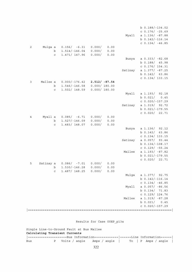
b 0.188/-134.02c 0.176/ -25.69
Myall a 1.136/ -87.88b 0.142/-116.14c 0.134/ -46.85
2 Mulga a 0.156/ -6.31 0.000/ 0.00b 1.514/-146.04 0.000/ 0.00c 1.471/ 147.96 0.000/ 0.00
Bunya a 0.333/ -82.68b 0.188/ 45.98c 0.176/ 154.31
Satinay a 1.377/ -87.25b 0.142/ 63.86c 0.134/ 133.15
3 Mallee a 0.000/-176.42 2.512/ -87.54b 1.546/-146.58 0.000/ 180.00c 1.502/ 148.59 0.000/ 180.00
Myall a 1.193/ 92.18b 0.021/ 0.45c 0.020/-157.29
Satinay a 1.319/ 92.72b 0.021/-179.55c 0.020/ 22.71
4 Myall a 0.085/ -6.71 0.000/ 0.00b 1.527/-146.09 0.000/ 0.00c 1.483/ 148.07 0.000/ 0.00
Bunya a 1.136/ 92.12b 0.142/ 63.86c 0.134/ 133.15
Satinay a 0.057/ 93.44b 0.134/-108.17c 0.129/ -55.24
Mallee a 1.193/ -87.82b 0.021/-179.55c 0.020/ 22.71
5 Satinay a 0.086/ -7.01 0.000/ 0.00b 1.530/-146.28 0.000/ 0.00c 1.487/ 148.25 0.000/ 0.00
Mulga a 1.377/ 92.75b 0.142/-116.14c 0.134/ -46.85
Myall a 0.057/ -86.56b 0.134/ 71.83c 0.129/ 124.76
Mallee a 1.319/ -87.28b 0.021/ 0.45c 0.020/-157.29
|==============================================================================|
Results for Case OOEP_p13a
Single Line-to-Ground Fault at Bus MalleeCalculating Transient Currents|=====================Bus Information=============|======Line Information======|Bus P Volts / angle Amps / angle | To | P Amps / angle |
322
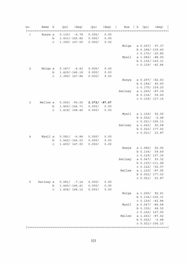
no. Name h (pu) (deg) (pu) (deg) | Bus | h (pu) (deg) ||==============================================================================|
1 Bunya a 0.130/ -6.78 0.000/ 0.00b 1.431/-145.82 0.000/ 0.00c 1.390/ 147.50 0.000/ 0.00
Mulga a 0.297/ 97.37b 0.184/-139.40c 0.175/ -20.80
Myall a 1.082/ -88.00b 0.134/-120.31c 0.129/ -42.84
2 Mulga a 0.147/ -6.43 0.000/ 0.00b 1.429/-146.18 0.000/ 0.00c 1.389/ 147.84 0.000/ 0.00
Bunya a 0.297/ -82.63b 0.184/ 40.60c 0.175/ 159.20
Satinay a 1.290/ -87.39b 0.134/ 59.69c 0.129/ 137.16
3 Mallee a 0.000/ -90.00 2.372/ -87.67b 1.460/-146.71 0.000/ 0.00c 1.418/ 148.46 0.000/ 0.00
Myall a 1.129/ 92.05b 0.022/ -2.48c 0.021/-156.13
Satinay a 1.243/ 92.58b 0.022/ 177.52c 0.021/ 23.87
4 Myall a 0.081/ -6.84 0.000/ 0.00b 1.442/-146.23 0.000/ 0.00c 1.400/ 147.93 0.000/ 0.00
Bunya a 1.082/ 92.00b 0.134/ 59.69c 0.129/ 137.16
Satinay a 0.047/ 93.32b 0.125/-111.48c 0.122/ -52.07
Mallee a 1.129/ -87.95b 0.022/ 177.52c 0.021/ 23.87
5 Satinay a 0.081/ -7.14 0.000/ 0.00b 1.445/-146.41 0.000/ 0.00c 1.404/ 148.12 0.000/ 0.00
Mulga a 1.290/ 92.61b 0.134/-120.31c 0.129/ -42.84
Myall a 0.047/ -86.68b 0.125/ 68.52c 0.122/ 127.93
Mallee a 1.243/ -87.42b 0.022/ -2.48c 0.021/-156.13
|==============================================================================|
323
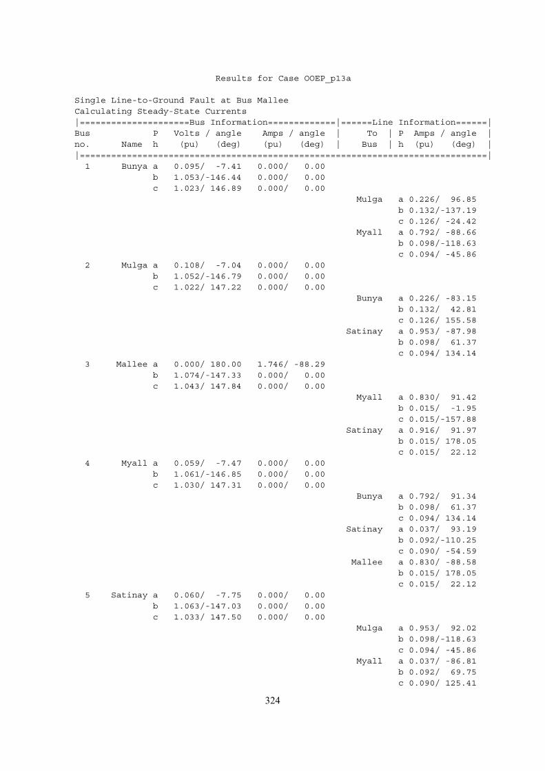
Results for Case OOEP_p13a
Single Line-to-Ground Fault at Bus MalleeCalculating Steady-State Currents|=====================Bus Information=============|======Line Information======|Bus P Volts / angle Amps / angle | To | P Amps / angle |no. Name h (pu) (deg) (pu) (deg) | Bus | h (pu) (deg) ||==============================================================================|
1 Bunya a 0.095/ -7.41 0.000/ 0.00b 1.053/-146.44 0.000/ 0.00c 1.023/ 146.89 0.000/ 0.00
Mulga a 0.226/ 96.85b 0.132/-137.19c 0.126/ -24.42
Myall a 0.792/ -88.66b 0.098/-118.63c 0.094/ -45.86
2 Mulga a 0.108/ -7.04 0.000/ 0.00b 1.052/-146.79 0.000/ 0.00c 1.022/ 147.22 0.000/ 0.00
Bunya a 0.226/ -83.15b 0.132/ 42.81c 0.126/ 155.58
Satinay a 0.953/ -87.98b 0.098/ 61.37c 0.094/ 134.14
3 Mallee a 0.000/ 180.00 1.746/ -88.29b 1.074/-147.33 0.000/ 0.00c 1.043/ 147.84 0.000/ 0.00
Myall a 0.830/ 91.42b 0.015/ -1.95c 0.015/-157.88
Satinay a 0.916/ 91.97b 0.015/ 178.05c 0.015/ 22.12
4 Myall a 0.059/ -7.47 0.000/ 0.00b 1.061/-146.85 0.000/ 0.00c 1.030/ 147.31 0.000/ 0.00
Bunya a 0.792/ 91.34b 0.098/ 61.37c 0.094/ 134.14
Satinay a 0.037/ 93.19b 0.092/-110.25c 0.090/ -54.59
Mallee a 0.830/ -88.58b 0.015/ 178.05c 0.015/ 22.12
5 Satinay a 0.060/ -7.75 0.000/ 0.00b 1.063/-147.03 0.000/ 0.00c 1.033/ 147.50 0.000/ 0.00
Mulga a 0.953/ 92.02b 0.098/-118.63c 0.094/ -45.86
Myall a 0.037/ -86.81b 0.092/ 69.75c 0.090/ 125.41
324
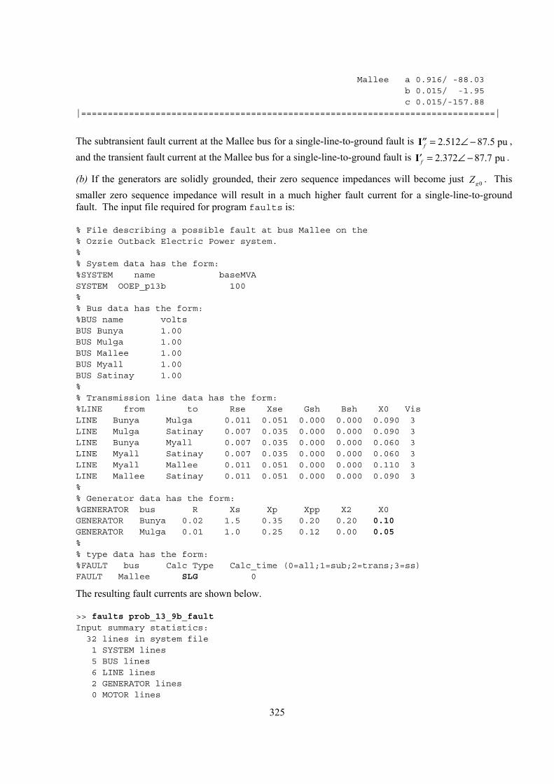
Mallee a 0.916/ -88.03b 0.015/ -1.95c 0.015/-157.88
|==============================================================================|
The subtransient fault current at the Mallee bus for a single-line-to-ground fault is I , and the transient fault current at the Mallee bus for a single-line-to-ground fault is I .
2.512 87.5 puf = ∠ −′′2.372 87.7 puf = ∠ −′
(b) If the generators are solidly grounded, their zero sequence impedances will become just 0gZ . This smaller zero sequence impedance will result in a much higher fault current for a single-line-to-ground fault. The input file required for program faults is:
% File describing a possible fault at bus Mallee on the% Ozzie Outback Electric Power system.%% System data has the form:%SYSTEM name baseMVASYSTEM OOEP_p13b 100%% Bus data has the form:%BUS name voltsBUS Bunya 1.00BUS Mulga 1.00BUS Mallee 1.00BUS Myall 1.00BUS Satinay 1.00%% Transmission line data has the form:%LINE from to Rse Xse Gsh Bsh X0 VisLINE Bunya Mulga 0.011 0.051 0.000 0.000 0.090 3LINE Mulga Satinay 0.007 0.035 0.000 0.000 0.090 3LINE Bunya Myall 0.007 0.035 0.000 0.000 0.060 3LINE Myall Satinay 0.007 0.035 0.000 0.000 0.060 3LINE Myall Mallee 0.011 0.051 0.000 0.000 0.110 3LINE Mallee Satinay 0.011 0.051 0.000 0.000 0.090 3%% Generator data has the form:%GENERATOR bus R Xs Xp Xpp X2 X0GENERATOR Bunya 0.02 1.5 0.35 0.20 0.20 0.10GENERATOR Mulga 0.01 1.0 0.25 0.12 0.00 0.05%% type data has the form:%FAULT bus Calc Type Calc_time (0=all;1=sub;2=trans;3=ss)FAULT Mallee SLG 0
The resulting fault currents are shown below.
>> faults prob_13_9b_faultInput summary statistics:
32 lines in system file1 SYSTEM lines5 BUS lines6 LINE lines2 GENERATOR lines0 MOTOR lines
325
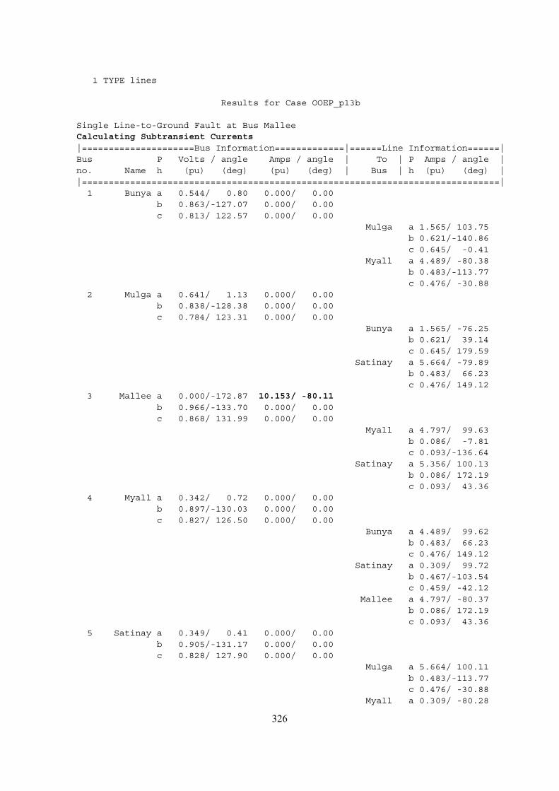
1 TYPE lines
Results for Case OOEP_p13b
Single Line-to-Ground Fault at Bus MalleeCalculating Subtransient Currents|=====================Bus Information=============|======Line Information======|Bus P Volts / angle Amps / angle | To | P Amps / angle |no. Name h (pu) (deg) (pu) (deg) | Bus | h (pu) (deg) ||==============================================================================|
1 Bunya a 0.544/ 0.80 0.000/ 0.00b 0.863/-127.07 0.000/ 0.00c 0.813/ 122.57 0.000/ 0.00
Mulga a 1.565/ 103.75b 0.621/-140.86c 0.645/ -0.41
Myall a 4.489/ -80.38b 0.483/-113.77c 0.476/ -30.88
2 Mulga a 0.641/ 1.13 0.000/ 0.00b 0.838/-128.38 0.000/ 0.00c 0.784/ 123.31 0.000/ 0.00
Bunya a 1.565/ -76.25b 0.621/ 39.14c 0.645/ 179.59
Satinay a 5.664/ -79.89b 0.483/ 66.23c 0.476/ 149.12
3 Mallee a 0.000/-172.87 10.153/ -80.11b 0.966/-133.70 0.000/ 0.00c 0.868/ 131.99 0.000/ 0.00
Myall a 4.797/ 99.63b 0.086/ -7.81c 0.093/-136.64
Satinay a 5.356/ 100.13b 0.086/ 172.19c 0.093/ 43.36
4 Myall a 0.342/ 0.72 0.000/ 0.00b 0.897/-130.03 0.000/ 0.00c 0.827/ 126.50 0.000/ 0.00
Bunya a 4.489/ 99.62b 0.483/ 66.23c 0.476/ 149.12
Satinay a 0.309/ 99.72b 0.467/-103.54c 0.459/ -42.12
Mallee a 4.797/ -80.37b 0.086/ 172.19c 0.093/ 43.36
5 Satinay a 0.349/ 0.41 0.000/ 0.00b 0.905/-131.17 0.000/ 0.00c 0.828/ 127.90 0.000/ 0.00
Mulga a 5.664/ 100.11b 0.483/-113.77c 0.476/ -30.88
Myall a 0.309/ -80.28
326
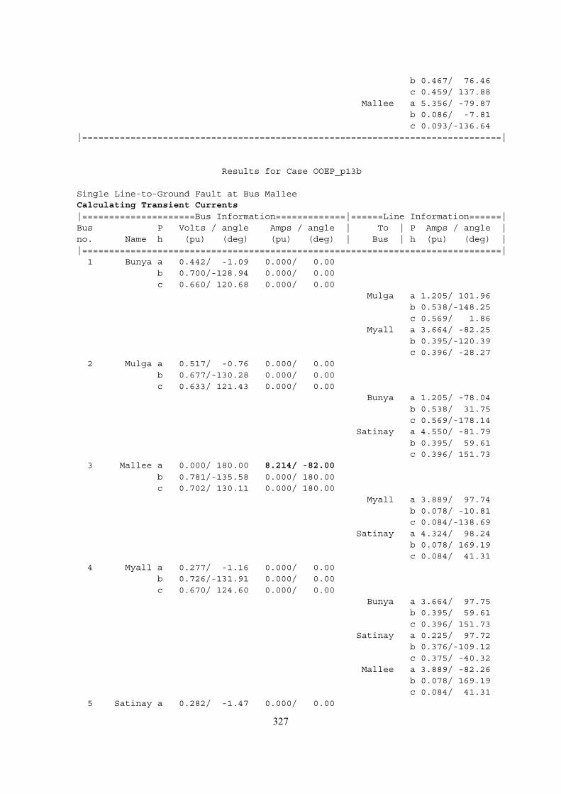
b 0.467/ 76.46c 0.459/ 137.88
Mallee a 5.356/ -79.87b 0.086/ -7.81c 0.093/-136.64
|==============================================================================|
Results for Case OOEP_p13b
Single Line-to-Ground Fault at Bus MalleeCalculating Transient Currents|=====================Bus Information=============|======Line Information======|Bus P Volts / angle Amps / angle | To | P Amps / angle |no. Name h (pu) (deg) (pu) (deg) | Bus | h (pu) (deg) ||==============================================================================|
1 Bunya a 0.442/ -1.09 0.000/ 0.00b 0.700/-128.94 0.000/ 0.00c 0.660/ 120.68 0.000/ 0.00
Mulga a 1.205/ 101.96b 0.538/-148.25c 0.569/ 1.86
Myall a 3.664/ -82.25b 0.395/-120.39c 0.396/ -28.27
2 Mulga a 0.517/ -0.76 0.000/ 0.00b 0.677/-130.28 0.000/ 0.00c 0.633/ 121.43 0.000/ 0.00
Bunya a 1.205/ -78.04b 0.538/ 31.75c 0.569/-178.14
Satinay a 4.550/ -81.79b 0.395/ 59.61c 0.396/ 151.73
3 Mallee a 0.000/ 180.00 8.214/ -82.00b 0.781/-135.58 0.000/ 180.00c 0.702/ 130.11 0.000/ 180.00
Myall a 3.889/ 97.74b 0.078/ -10.81c 0.084/-138.69
Satinay a 4.324/ 98.24b 0.078/ 169.19c 0.084/ 41.31
4 Myall a 0.277/ -1.16 0.000/ 0.00b 0.726/-131.91 0.000/ 0.00c 0.670/ 124.60 0.000/ 0.00
Bunya a 3.664/ 97.75b 0.395/ 59.61c 0.396/ 151.73
Satinay a 0.225/ 97.72b 0.376/-109.12c 0.375/ -40.32
Mallee a 3.889/ -82.26b 0.078/ 169.19c 0.084/ 41.31
5 Satinay a 0.282/ -1.47 0.000/ 0.00
327
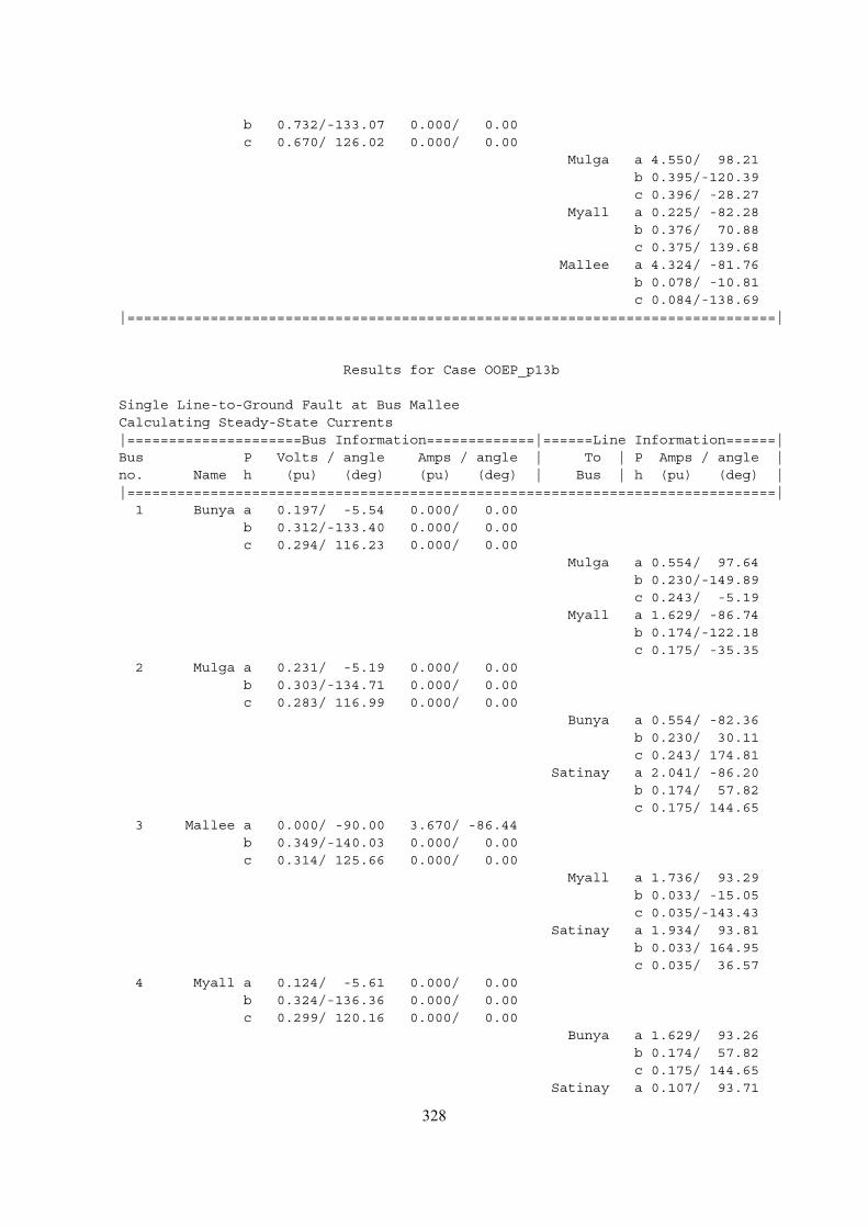
b 0.732/-133.07 0.000/ 0.00c 0.670/ 126.02 0.000/ 0.00
Mulga a 4.550/ 98.21b 0.395/-120.39c 0.396/ -28.27
Myall a 0.225/ -82.28b 0.376/ 70.88c 0.375/ 139.68
Mallee a 4.324/ -81.76b 0.078/ -10.81c 0.084/-138.69
|==============================================================================|
Results for Case OOEP_p13b
Single Line-to-Ground Fault at Bus MalleeCalculating Steady-State Currents|=====================Bus Information=============|======Line Information======|Bus P Volts / angle Amps / angle | To | P Amps / angle |no. Name h (pu) (deg) (pu) (deg) | Bus | h (pu) (deg) ||==============================================================================|
1 Bunya a 0.197/ -5.54 0.000/ 0.00b 0.312/-133.40 0.000/ 0.00c 0.294/ 116.23 0.000/ 0.00
Mulga a 0.554/ 97.64b 0.230/-149.89c 0.243/ -5.19
Myall a 1.629/ -86.74b 0.174/-122.18c 0.175/ -35.35
2 Mulga a 0.231/ -5.19 0.000/ 0.00b 0.303/-134.71 0.000/ 0.00c 0.283/ 116.99 0.000/ 0.00
Bunya a 0.554/ -82.36b 0.230/ 30.11c 0.243/ 174.81
Satinay a 2.041/ -86.20b 0.174/ 57.82c 0.175/ 144.65
3 Mallee a 0.000/ -90.00 3.670/ -86.44b 0.349/-140.03 0.000/ 0.00c 0.314/ 125.66 0.000/ 0.00
Myall a 1.736/ 93.29b 0.033/ -15.05c 0.035/-143.43
Satinay a 1.934/ 93.81b 0.033/ 164.95c 0.035/ 36.57
4 Myall a 0.124/ -5.61 0.000/ 0.00b 0.324/-136.36 0.000/ 0.00c 0.299/ 120.16 0.000/ 0.00
Bunya a 1.629/ 93.26b 0.174/ 57.82c 0.175/ 144.65
Satinay a 0.107/ 93.71
328
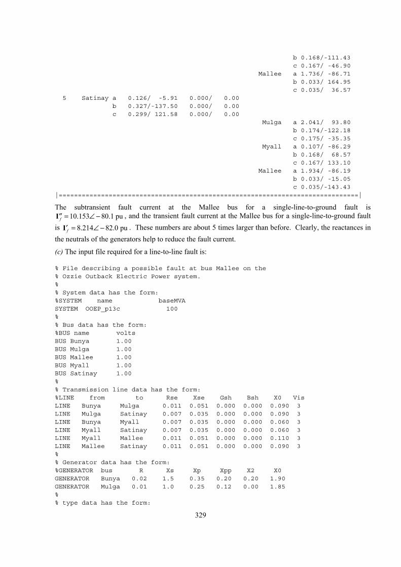
b 0.168/-111.43c 0.167/ -46.90
Mallee a 1.736/ -86.71b 0.033/ 164.95c 0.035/ 36.57
5 Satinay a 0.126/ -5.91 0.000/ 0.00b 0.327/-137.50 0.000/ 0.00c 0.299/ 121.58 0.000/ 0.00
Mulga a 2.041/ 93.80b 0.174/-122.18c 0.175/ -35.35
Myall a 0.107/ -86.29b 0.168/ 68.57c 0.167/ 133.10
Mallee a 1.934/ -86.19b 0.033/ -15.05c 0.035/-143.43
|==============================================================================|
The subtransient fault current at the Mallee bus for a single-line-to-ground fault is , and the transient fault current at the Mallee bus for a single-line-to-ground fault
is . These numbers are about 5 times larger than before. Clearly, the reactances in the neutrals of the generators help to reduce the fault current.
10.153 80.1 puf = ∠ −′′I8.214 82.0 puf = ∠ −′I
(c) The input file required for a line-to-line fault is:
% File describing a possible fault at bus Mallee on the% Ozzie Outback Electric Power system.%% System data has the form:%SYSTEM name baseMVASYSTEM OOEP_p13c 100%% Bus data has the form:%BUS name voltsBUS Bunya 1.00BUS Mulga 1.00BUS Mallee 1.00BUS Myall 1.00BUS Satinay 1.00%% Transmission line data has the form:%LINE from to Rse Xse Gsh Bsh X0 VisLINE Bunya Mulga 0.011 0.051 0.000 0.000 0.090 3LINE Mulga Satinay 0.007 0.035 0.000 0.000 0.090 3LINE Bunya Myall 0.007 0.035 0.000 0.000 0.060 3LINE Myall Satinay 0.007 0.035 0.000 0.000 0.060 3LINE Myall Mallee 0.011 0.051 0.000 0.000 0.110 3LINE Mallee Satinay 0.011 0.051 0.000 0.000 0.090 3%% Generator data has the form:%GENERATOR bus R Xs Xp Xpp X2 X0GENERATOR Bunya 0.02 1.5 0.35 0.20 0.20 1.90GENERATOR Mulga 0.01 1.0 0.25 0.12 0.00 1.85%% type data has the form:
329
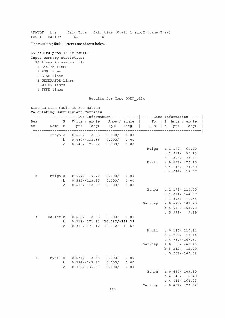
%FAULT bus Calc Type Calc_time (0=all;1=sub;2=trans;3=ss)FAULT Mallee LL 0
The resulting fault currents are shown below.
>> faults prob_13_9c_faultInput summary statistics:
32 lines in system file1 SYSTEM lines5 BUS lines6 LINE lines2 GENERATOR lines0 MOTOR lines1 TYPE lines
Results for Case OOEP_p13c
Line-to-Line Fault at Bus MalleeCalculating Subtransient Currents|=====================Bus Information=============|======Line Information======|Bus P Volts / angle Amps / angle | To | P Amps / angle |no. Name h (pu) (deg) (pu) (deg) | Bus | h (pu) (deg) ||==============================================================================|
1 Bunya a 0.656/ -8.08 0.000/ 0.00b 0.480/-133.36 0.000/ 0.00c 0.545/ 125.92 0.000/ 0.00
Mulga a 1.178/ -69.30b 1.811/ 35.43c 1.893/ 178.44
Myall a 0.627/ -70.10b 4.146/-173.60c 4.046/ 15.07
2 Mulga a 0.597/ -9.77 0.000/ 0.00b 0.525/-123.85 0.000/ 0.00c 0.613/ 118.87 0.000/ 0.00
Bunya a 1.178/ 110.70b 1.811/-144.57c 1.893/ -1.56
Satinay a 0.627/ 109.90b 5.916/-164.72c 5.999/ 9.29
3 Mallee a 0.626/ -8.88 0.000/ 0.00b 0.313/ 171.12 10.032/-168.38c 0.313/ 171.12 10.032/ 11.62
Myall a 0.160/ 110.54b 4.792/ 10.44c 4.767/-167.67
Satinay a 0.160/ -69.46b 5.242/ 12.70c 5.267/-169.02
4 Myall a 0.634/ -8.66 0.000/ 0.00b 0.376/-147.54 0.000/ 0.00c 0.429/ 136.23 0.000/ 0.00
Bunya a 0.627/ 109.90b 4.146/ 6.40c 4.046/-164.93
Satinay a 0.467/ -70.32
330
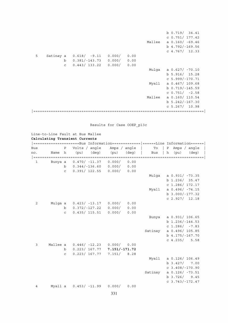
b 0.719/ 34.41c 0.751/ 177.42
Mallee a 0.160/ -69.46b 4.792/-169.56c 4.767/ 12.33
5 Satinay a 0.618/ -9.11 0.000/ 0.00b 0.381/-143.73 0.000/ 0.00c 0.443/ 133.22 0.000/ 0.00
Mulga a 0.627/ -70.10b 5.916/ 15.28c 5.999/-170.71
Myall a 0.467/ 109.68b 0.719/-145.59c 0.751/ -2.58
Mallee a 0.160/ 110.54b 5.242/-167.30c 5.267/ 10.98
|==============================================================================|
Results for Case OOEP_p13c
Line-to-Line Fault at Bus MalleeCalculating Transient Currents|=====================Bus Information=============|======Line Information======|Bus P Volts / angle Amps / angle | To | P Amps / angle |no. Name h (pu) (deg) (pu) (deg) | Bus | h (pu) (deg) ||==============================================================================|
1 Bunya a 0.470/ -11.37 0.000/ 0.00b 0.344/-136.60 0.000/ 0.00c 0.391/ 122.55 0.000/ 0.00
Mulga a 0.931/ -73.35b 1.236/ 35.47c 1.286/ 172.17
Myall a 0.496/ -74.15b 3.000/-177.32c 2.927/ 12.18
2 Mulga a 0.423/ -13.17 0.000/ 0.00b 0.372/-127.22 0.000/ 0.00c 0.435/ 115.51 0.000/ 0.00
Bunya a 0.931/ 106.65b 1.236/-144.53c 1.286/ -7.83
Satinay a 0.496/ 105.85b 4.175/-167.70c 4.235/ 5.58
3 Mallee a 0.446/ -12.23 0.000/ 0.00b 0.223/ 167.77 7.151/-171.72c 0.223/ 167.77 7.151/ 8.28
Myall a 0.126/ 106.49b 3.427/ 7.00c 3.408/-170.90
Satinay a 0.126/ -73.51b 3.726/ 9.45c 3.743/-172.47
4 Myall a 0.453/ -11.99 0.000/ 0.00
331
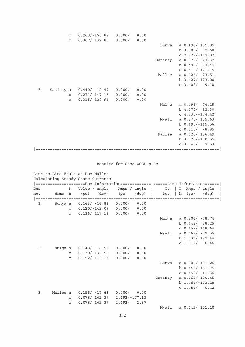
b 0.268/-150.82 0.000/ 0.00c 0.307/ 132.85 0.000/ 0.00
Bunya a 0.496/ 105.85b 3.000/ 2.68c 2.927/-167.82
Satinay a 0.370/ -74.37b 0.490/ 34.44c 0.510/ 171.15
Mallee a 0.126/ -73.51b 3.427/-173.00c 3.408/ 9.10
5 Satinay a 0.440/ -12.47 0.000/ 0.00b 0.271/-147.13 0.000/ 0.00c 0.315/ 129.91 0.000/ 0.00
Mulga a 0.496/ -74.15b 4.175/ 12.30c 4.235/-174.42
Myall a 0.370/ 105.63b 0.490/-145.56c 0.510/ -8.85
Mallee a 0.126/ 106.49b 3.726/-170.55c 3.743/ 7.53
|==============================================================================|
Results for Case OOEP_p13c
Line-to-Line Fault at Bus MalleeCalculating Steady-State Currents|=====================Bus Information=============|======Line Information======|Bus P Volts / angle Amps / angle | To | P Amps / angle |no. Name h (pu) (deg) (pu) (deg) | Bus | h (pu) (deg) ||==============================================================================|
1 Bunya a 0.163/ -16.83 0.000/ 0.00b 0.120/-142.09 0.000/ 0.00c 0.136/ 117.13 0.000/ 0.00
Mulga a 0.306/ -78.74b 0.443/ 28.25c 0.459/ 168.64
Myall a 0.163/ -79.55b 1.036/ 177.44c 1.012/ 6.46
2 Mulga a 0.148/ -18.52 0.000/ 0.00b 0.130/-132.59 0.000/ 0.00c 0.152/ 110.13 0.000/ 0.00
Bunya a 0.306/ 101.26b 0.443/-151.75c 0.459/ -11.36
Satinay a 0.163/ 100.45b 1.464/-173.28c 1.484/ 0.42
3 Mallee a 0.156/ -17.63 0.000/ 0.00b 0.078/ 162.37 2.493/-177.13c 0.078/ 162.37 2.493/ 2.87
Myall a 0.042/ 101.10
332
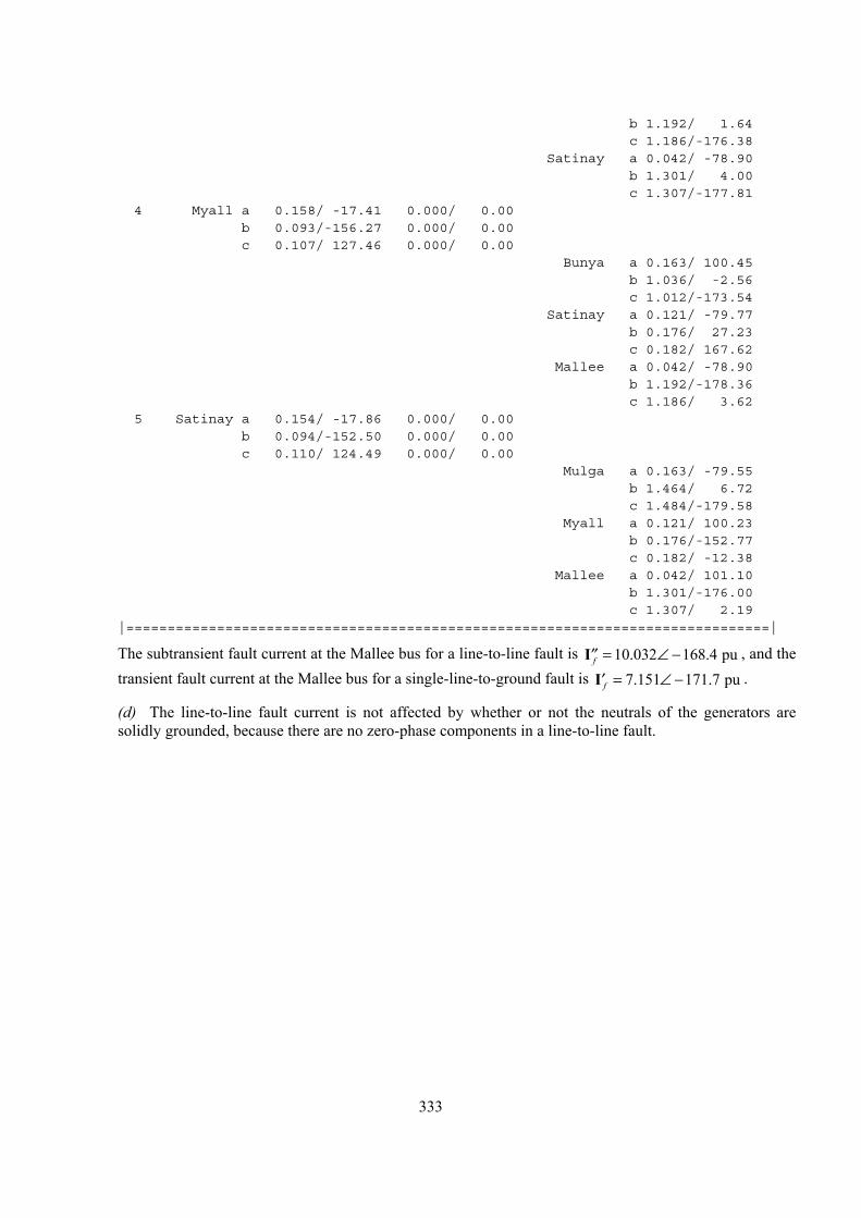
b 1.192/ 1.64c 1.186/-176.38
Satinay a 0.042/ -78.90b 1.301/ 4.00c 1.307/-177.81
4 Myall a 0.158/ -17.41 0.000/ 0.00b 0.093/-156.27 0.000/ 0.00c 0.107/ 127.46 0.000/ 0.00
Bunya a 0.163/ 100.45b 1.036/ -2.56c 1.012/-173.54
Satinay a 0.121/ -79.77b 0.176/ 27.23c 0.182/ 167.62
Mallee a 0.042/ -78.90b 1.192/-178.36c 1.186/ 3.62
5 Satinay a 0.154/ -17.86 0.000/ 0.00b 0.094/-152.50 0.000/ 0.00c 0.110/ 124.49 0.000/ 0.00
Mulga a 0.163/ -79.55b 1.464/ 6.72c 1.484/-179.58
Myall a 0.121/ 100.23b 0.176/-152.77c 0.182/ -12.38
Mallee a 0.042/ 101.10b 1.301/-176.00c 1.307/ 2.19
|==============================================================================|
The subtransient fault current at the Mallee bus for a line-to-line fault is I , and the transient fault current at the Mallee bus for a single-line-to-ground fault is I .
10.032 168.4 puf = ∠ −′′7.151 171.7 puf = ∠ −′
(d) The line-to-line fault current is not affected by whether or not the neutrals of the generators are solidly grounded, because there are no zero-phase components in a line-to-line fault.
333