
ISIS USERS MANUAL - Isaac Newton Group of Telescopes · MANUAL V ersion Octob er ... TV F ocus...
169
Transcript of ISIS USERS MANUAL - Isaac Newton Group of Telescopes · MANUAL V ersion Octob er ... TV F ocus...

Isaac Newton Group of Telescopes
William Herschel Telescope
ISIS USERS� MANUAL
Version ���
���� October
D� Carter� C�R� Benn� R�G�M� Rutten� J�M� Breare� P�J� Rudd� D�L� King� R�E�S� Clegg� V�S�Dhillon� S� Arribas� J��L� Rasilla� A� Garcia� C�R� Jenkins� P�A� Charles
The Isaac Newton Group of telescopes on La Palma is ownedby the UK Science and Engineering Research Council and oper�ated by the Royal Greenwich Observatory for the SERC in part�nership with the Organisatie voor Zuiver Wetenschappelijk Onder�zoek �ZWO� of the Netherlands� the Irish National Board for Sci�ence and Technology and the Dublin Institute for Advanced Studies�

ISIS Users� Manual CONTENTS
Contents
I Description of the Instruments �
� The Cassegrain A�G Box �
��� Design of the A�G unit � � � � � � � � � � � � � � � � � � � � � � � � � � � � � � � � �
��� Object acquisition � � � � � � � � � � � � � � � � � � � � � � � � � � � � � � � � � � � �
��� Slit viewing � � � � � � � � � � � � � � � � � � � � � � � � � � � � � � � � � � � � � � � �
�� Autoguider � � � � � � � � � � � � � � � � � � � � � � � � � � � � � � � � � � � � � � � �
���� Autoguider Geometry � � � � � � � � � � � � � � � � � � � � � � � � � � � � � �
�� Comparison lamps � � � � � � � � � � � � � � � � � � � � � � � � � � � � � � � � � � � �
��� Filters � � � � � � � � � � � � � � � � � � � � � � � � � � � � � � � � � � � � � � � � � �
��� Polarisation calibration � � � � � � � � � � � � � � � � � � � � � � � � � � � � � � � �
�� Auxiliary focus � � � � � � � � � � � � � � � � � � � � � � � � � � � � � � � � � � � � �
� ISIS and FOS�II Spectrographs �
��� Overall layout � � � � � � � � � � � � � � � � � � � � � � � � � � � � � � � � � � � � � � �
��� Polarisation optics � � � � � � � � � � � � � � � � � � � � � � � � � � � � � � � � � � � �
��� The slit area � � � � � � � � � � � � � � � � � � � � � � � � � � � � � � � � � � � � � �
�� Folds and Dichroics � � � � � � � � � � � � � � � � � � � � � � � � � � � � � � � � � � �
�� Below Slit �lters � � � � � � � � � � � � � � � � � � � � � � � � � � � � � � � � � � � � ��
��� Collimators � � � � � � � � � � � � � � � � � � � � � � � � � � � � � � � � � � � � � � � ��
��� The ISIS gratings � � � � � � � � � � � � � � � � � � � � � � � � � � � � � � � � � � � � ��
�� Cameras � � � � � � � � � � � � � � � � � � � � � � � � � � � � � � � � � � � � � � � � � ��
��� Cross�Dispersers � � � � � � � � � � � � � � � � � � � � � � � � � � � � � � � � � � � � ��
���� The Faint Object Spectrograph �FOS�II� � � � � � � � � � � � � � � � � � � � � � � � ��
���� Multi�Slit Unit � � � � � � � � � � � � � � � � � � � � � � � � � � � � � � � � � � � � � ��
���� Then ISIS Fibre System � � � � � � � � � � � � � � � � � � � � � � � � � � � � � � � � ��
������ Auxiliary focus mounting � � � � � � � � � � � � � � � � � � � � � � � � � � � ��
������ Fibre Bundle � � � � � � � � � � � � � � � � � � � � � � � � � � � � � � � � � � �
������ Guiding system� � � � � � � � � � � � � � � � � � � � � � � � � � � � � � � � � �
����� Aperture plates � � � � � � � � � � � � � � � � � � � � � � � � � � � � � � � � � ��
����� Observing coordinate determination� � � � � � � � � � � � � � � � � � � � � � ��
������ Overall Performance � � � � � � � � � � � � � � � � � � � � � � � � � � � � � � �
� Performance ��
��� Throughput � � � � � � � � � � � � � � � � � � � � � � � � � � � � � � � � � � � � � � � �
��� Stability and radial velocities � � � � � � � � � � � � � � � � � � � � � � � � � � � � � �
��� Scattered Light � � � � � � � � � � � � � � � � � � � � � � � � � � � � � � � � � � � � � �
�� Wood�s Anomalies in the ISIS gratings � � � � � � � � � � � � � � � � � � � � � � � � �
II Detectors ��
i

CONTENTS ISIS Users� Manual
� CCD Detectors ��
�� Schematic view of the CCD systems � � � � � � � � � � � � � � � � � � � � � � � � � ���� CCD chips in current use at the WHT � � � � � � � � � � � � � � � � � � � � � � � � ��
� The CCDIPCS Detector ��
�� Scienti�c Description � � � � � � � � � � � � � � � � � � � � � � � � � � � � � � � � � � ���� CCD�IPCS granularity and Dithering � � � � � � � � � � � � � � � � � � � � � � � � �
� Overall performance of the system ��
III Computers and Operations ��
Control System ��
��� Control system overview � � � � � � � � � � � � � � � � � � � � � � � � � � � � � � � � ����� The Detector Memory System � � � � � � � � � � � � � � � � � � � � � � � � � � � � � ����� The SPARCstation � � � � � � � � � � � � � � � � � � � � � � � � � � � � � � � � � � � ���� The Utility Network � � � � � � � � � � � � � � � � � � � � � � � � � � � � � � � � � � ���� The System Computer and User Interface � � � � � � � � � � � � � � � � � � � � � � ����� The MIMIC display � � � � � � � � � � � � � � � � � � � � � � � � � � � � � � � � � � ���� Generating Data Tapes � � � � � � � � � � � � � � � � � � � � � � � � � � � � � � � � ��� Engineering terminals � � � � � � � � � � � � � � � � � � � � � � � � � � � � � � � � � �
�� �� The Engineering MIMIC � � � � � � � � � � � � � � � � � � � � � � � � � � � � ��� �� Direct control of the Cassegrain Instruments � � � � � � � � � � � � � � � � ��� �� The Detector engineering control terminal � � � � � � � � � � � � � � � � � � �
IV SETUP AND OBSERVING PROCEDURES ��
� Setup Procedures ��
�� Starting the computer systems � � � � � � � � � � � � � � � � � � � � � � � � � � � � � �� Con�guration of the A�G Box and Spectrograph � � � � � � � � � � � � � � � � � � �
���� Changing Gratings � � � � � � � � � � � � � � � � � � � � � � � � � � � � � � � � ���� Changing Filters in the Main �A�G box� slides � � � � � � � � � � � � � � � � ���� Changing components in the slit area � � � � � � � � � � � � � � � � � � � � ��� Directing light to the right cameras � � � � � � � � � � � � � � � � � � � � � � ��� Setting Grating Angles � � � � � � � � � � � � � � � � � � � � � � � � � � � � � � ���� The Slit Area � � � � � � � � � � � � � � � � � � � � � � � � � � � � � � � � � � � ���� Con�guring the Spectrograph for Spectropolarimetry � � � � � � � � � � � � �
�� Setting up the CCD Detectors � � � � � � � � � � � � � � � � � � � � � � � � � � � � � ���� Rotation � � � � � � � � � � � � � � � � � � � � � � � � � � � � � � � � � � � � � � ���� Tilt and coarse Focus � � � � � � � � � � � � � � � � � � � � � � � � � � � � � � ���� Collimator Focus � � � � � � � � � � � � � � � � � � � � � � � � � � � � � � � � ��� Hartmann test using the DMS � � � � � � � � � � � � � � � � � � � � � � � � ��� Hartmann test using the Vax � � � � � � � � � � � � � � � � � � � � � � � � � � ���� Minimum�FWHM using the VAX � � � � � � � � � � � � � � � � � � � � � � � �
� Setting up the IPCS � � � � � � � � � � � � � � � � � � � � � � � � � � � � � � � � � � �
ii

ISIS Users� Manual CONTENTS
��� Camera Head Rotation � � � � � � � � � � � � � � � � � � � � � � � � � � � � �
��� S�Distortion Correction � � � � � � � � � � � � � � � � � � � � � � � � � � � �
��� Collimator Focus � � � � � � � � � � � � � � � � � � � � � � � � � � � � � � � � ��
�� Hartmann test using the DMS � � � � � � � � � � � � � � � � � � � � � � � � ��
�� Hartmann test using the Vax ��� � � � � � � � � � � � � � � � � � � � � � � ��
��� Minimum�FWHM using the VAX � � � � � � � � � � � � � � � � � � � � � � � ��
� Installation and Setup for Fibre observing � � � � � � � � � � � � � � � � � � � � � � ��
��� Fibre slit mounting � � � � � � � � � � � � � � � � � � � � � � � � � � � � � � � ��
��� Fibre slit alignment � � � � � � � � � � � � � � � � � � � � � � � � � � � � � � ��
��� Guide �bre bundle focussing � � � � � � � � � � � � � � � � � � � � � � � � � �
�� Spectrograph set up � � � � � � � � � � � � � � � � � � � � � � � � � � � � � � �
�� Setting up FOS � � � � � � � � � � � � � � � � � � � � � � � � � � � � � � � � � � � � � �
� Observing Procedures ��
��� Observing with one or two CCDs � � � � � � � � � � � � � � � � � � � � � � � � � � � ��
����� TV Focus � � � � � � � � � � � � � � � � � � � � � � � � � � � � � � � � � � � � ��
����� Instrument Calibration Data � � � � � � � � � � � � � � � � � � � � � � � � � ��
����� Acquiring data on the sky � � � � � � � � � � � � � � � � � � � � � � � � � � � ��
���� Acquiring faint objects � � � � � � � � � � � � � � � � � � � � � � � � � � � � � ��
���� Acquiring guide stars � � � � � � � � � � � � � � � � � � � � � � � � � � � � � ��
����� Wavelength Calibration � � � � � � � � � � � � � � � � � � � � � � � � � � � � ��
��� Observing with IPCS only or with CCD and IPCS � � � � � � � � � � � � � � � � � ��
����� TV Focus � � � � � � � � � � � � � � � � � � � � � � � � � � � � � � � � � � � � ��
����� Switching on the IPCS EHT voltage � � � � � � � � � � � � � � � � � � � � � ��
����� Instrument Calibration Data � � � � � � � � � � � � � � � � � � � � � � � � � �
���� Acquiring data on the sky � � � � � � � � � � � � � � � � � � � � � � � � � � � ��
��� Time�resolved observations with ISIS � � � � � � � � � � � � � � � � � � � � � � � � � ��
����� Sources of dead�time � � � � � � � � � � � � � � � � � � � � � � � � � � � � � � ��
����� Reducing dead�time � � � � � � � � � � � � � � � � � � � � � � � � � � � � � � ��
����� Future developments � � � � � � � � � � � � � � � � � � � � � � � � � � � � � � ��
���� A note on accurate time and ISIS � � � � � � � � � � � � � � � � � � � � � � � ��
�� Observing with FOS � � � � � � � � � � � � � � � � � � � � � � � � � � � � � � � � � � �
���� Data reduction � � � � � � � � � � � � � � � � � � � � � � � � � � � � � � � � � �
�� Spectropolarimetry � � � � � � � � � � � � � � � � � � � � � � � � � � � � � � � � � � � �
���� How to derive the Stokes parameters � � � � � � � � � � � � � � � � � � � � � �
���� Imaging Polarimetry � � � � � � � � � � � � � � � � � � � � � � � � � � � � � � �
��� Observing with Fibres � � � � � � � � � � � � � � � � � � � � � � � � � � � � � � � � �
����� Telescope focusing on the aperture plate� � � � � � � � � � � � � � � � � � �
����� Adjustment of the rotator axis and orientation� � � � � � � � � � � � � � � �
����� Field acquisition � � � � � � � � � � � � � � � � � � � � � � � � � � � � � � � �
���� Calibration � � � � � � � � � � � � � � � � � � � � � � � � � � � � � � � � � � � �
���� Data reduction � � � � � � � � � � � � � � � � � � � � � � � � � � � � � � � � � �
V QUICK REFERENCE GUIDE ��
iii

CONTENTS ISIS Users� Manual
�� Quick Reference Guide �
���� Starting Up � � � � � � � � � � � � � � � � � � � � � � � � � � � � � � � � � � � � � � � �
���� Taking Data � the Data Acquisition System � � � � � � � � � � � � � � � � � � � � � ����� Setting Up The CCDs � � � � � � � � � � � � � � � � � � � � � � � � � � � � � � � � �
������ Rotation and Focus � � � � � � � � � � � � � � � � � � � � � � � � � � � � � � ���� Setting Up The IPCS � � � � � � � � � � � � � � � � � � � � � � � � � � � � � � � � � �
����� Starting Up and Scan Correction � � � � � � � � � � � � � � � � � � � � � � � ������ Setting up the IPCS Format� and Focussing ISIS � � � � � � � � � � � � � � ������� Observing with IPCS � � � � � � � � � � � � � � � � � � � � � � � � � � � � � ��
��� The DMS Display � � � � � � � � � � � � � � � � � � � � � � � � � � � � � � � � � � � ��
���� ISIS Commands � � � � � � � � � � � � � � � � � � � � � � � � � � � � � � � � � � � � � �������� Slit area � � � � � � � � � � � � � � � � � � � � � � � � � � � � � � � � � � � � � �������� Folds and Filters � � � � � � � � � � � � � � � � � � � � � � � � � � � � � � � � �������� Gratings and Wavelength Settings � � � � � � � � � � � � � � � � � � � � � � ��
����� Polarisation Module � � � � � � � � � � � � � � � � � � � � � � � � � � � � � � ������� Initialising mechanisms � � � � � � � � � � � � � � � � � � � � � � � � � � � � ��
���� A�G Box Commands � � � � � � � � � � � � � � � � � � � � � � � � � � � � � � � � � ������� Comparison lamps � � � � � � � � � � � � � � � � � � � � � � � � � � � � � � � �
������ Autoguider � � � � � � � � � � � � � � � � � � � � � � � � � � � � � � � � � � � ���� Typical Observing Sequence � � � � � � � � � � � � � � � � � � � � � � � � � � � � � � ������ Observing With FOS � � � � � � � � � � � � � � � � � � � � � � � � � � � � � � � � � � �������O�setting the Telescope � � � � � � � � � � � � � � � � � � � � � � � � � � � � � � � � �������Blind O�sets � � � � � � � � � � � � � � � � � � � � � � � � � � � � � � � � � � � � � � ��
�������Small O�sets � � � � � � � � � � � � � � � � � � � � � � � � � � � � � � � � � � ���������Data Files � � � � � � � � � � � � � � � � � � � � � � � � � � � � � � � � � � � � �
�����Shutdown � � � � � � � � � � � � � � � � � � � � � � � � � � � � � � � � � � � � � � � � ��
VI COMMAND LISTS ���
�� Commands entered at the ICL interface ���
���� A�G Box Commands � � � � � � � � � � � � � � � � � � � � � � � � � � � � � � � � � ��������� AGACCESS � � � � � � � � � � � � � � � � � � � � � � � � � � � � � � � � � � ��������� AGBARCODES � � � � � � � � � � � � � � � � � � � � � � � � � � � � � � � � ��������� AGINIT � � � � � � � � � � � � � � � � � � � � � � � � � � � � � � � � � � � � � ���
����� AGMIRROR � � � � � � � � � � � � � � � � � � � � � � � � � � � � � � � � � � �������� AGUPDATE � � � � � � � � � � � � � � � � � � � � � � � � � � � � � � � � � � ��������� ARCOFF � � � � � � � � � � � � � � � � � � � � � � � � � � � � � � � � � � � � ��������� AUTOFILT � � � � � � � � � � � � � � � � � � � � � � � � � � � � � � � � � � � ���
����� AUTOFOCUS � � � � � � � � � � � � � � � � � � � � � � � � � � � � � � � � � ��������� AUTORADIAL � � � � � � � � � � � � � � � � � � � � � � � � � � � � � � � � � ����������AUTOTHETA � � � � � � � � � � � � � � � � � � � � � � � � � � � � � � � � � ����������AUXFILTER � � � � � � � � � � � � � � � � � � � � � � � � � � � � � � � � � � ���
�������COMPFILTA � � � � � � � � � � � � � � � � � � � � � � � � � � � � � � � � � � ����������COMPFILTB � � � � � � � � � � � � � � � � � � � � � � � � � � � � � � � � � � ���������COMPLAMPS � � � � � � � � � � � � � � � � � � � � � � � � � � � � � � � � � ���
iv

ISIS Users� Manual CONTENTS
������COMPND � � � � � � � � � � � � � � � � � � � � � � � � � � � � � � � � � � � � ����������CUARON � � � � � � � � � � � � � � � � � � � � � � � � � � � � � � � � � � � � ����������CUNEON � � � � � � � � � � � � � � � � � � � � � � � � � � � � � � � � � � � � ��������� MAINFILTC � � � � � � � � � � � � � � � � � � � � � � � � � � � � � � � � � � ����������MAINFILTND � � � � � � � � � � � � � � � � � � � � � � � � � � � � � � � � � ����������TV DIRECT �� � � � � � � � � � � � � � � � � � � � � � � � � � � � � � � � � ����������TV DIRECT � � � � � � � � � � � � � � � � � � � � � � � � � � � � � � � � � ���������TV SLIT �� � � � � � � � � � � � � � � � � � � � � � � � � � � � � � � � � � � ���������TV SLIT � � � � � � � � � � � � � � � � � � � � � � � � � � � � � � � � � � � ��������TVFILT � � � � � � � � � � � � � � � � � � � � � � � � � � � � � � � � � � � � � ��������TVFOCUS � � � � � � � � � � � � � � � � � � � � � � � � � � � � � � � � � � � ���������TVSCALE � � � � � � � � � � � � � � � � � � � � � � � � � � � � � � � � � � � ��
���� Autoguider Commands � � � � � � � � � � � � � � � � � � � � � � � � � � � � � � � � � �������� ACQINT � � � � � � � � � � � � � � � � � � � � � � � � � � � � � � � � � � � � �������� FIELD � � � � � � � � � � � � � � � � � � � � � � � � � � � � � � � � � � � � � � �������� FOLLOW � � � � � � � � � � � � � � � � � � � � � � � � � � � � � � � � � � � � ������� GUIINT � � � � � � � � � � � � � � � � � � � � � � � � � � � � � � � � � � � � � ��
���� ISIS Commands � � � � � � � � � � � � � � � � � � � � � � � � � � � � � � � � � � � � � �������� ANAMORPHOTIC � � � � � � � � � � � � � � � � � � � � � � � � � � � � � � �������� BCOLL � � � � � � � � � � � � � � � � � � � � � � � � � � � � � � � � � � � � � ��������� BLUEGRAT � � � � � � � � � � � � � � � � � � � � � � � � � � � � � � � � � � �������� BLUEXDISP � � � � � � � � � � � � � � � � � � � � � � � � � � � � � � � � � � �������� BFILTA � � � � � � � � � � � � � � � � � � � � � � � � � � � � � � � � � � � � � ��������� BFILTB � � � � � � � � � � � � � � � � � � � � � � � � � � � � � � � � � � � � � ��������� BFOLD � � � � � � � � � � � � � � � � � � � � � � � � � � � � � � � � � � � � � �������� BHART � � � � � � � � � � � � � � � � � � � � � � � � � � � � � � � � � � � � � ��������� CENWAVE � � � � � � � � � � � � � � � � � � � � � � � � � � � � � � � � � � � ����������CHANGE � � � � � � � � � � � � � � � � � � � � � � � � � � � � � � � � � � � � �� �������DEKKER � � � � � � � � � � � � � � � � � � � � � � � � � � � � � � � � � � � � �� �������FCP � � � � � � � � � � � � � � � � � � � � � � � � � � � � � � � � � � � � � � � �� �������GRATING DOOR � � � � � � � � � � � � � � � � � � � � � � � � � � � � � � � �� ������HW POLAR � � � � � � � � � � � � � � � � � � � � � � � � � � � � � � � � � � ���������ISIS CONFIG � � � � � � � � � � � � � � � � � � � � � � � � � � � � � � � � � ����������ISIS INIT � � � � � � � � � � � � � � � � � � � � � � � � � � � � � � � � � � � � ����������ISIS MOVE � � � � � � � � � � � � � � � � � � � � � � � � � � � � � � � � � � � ��������� ISIS UPDATE � � � � � � � � � � � � � � � � � � � � � � � � � � � � � � � � � ����������LID � � � � � � � � � � � � � � � � � � � � � � � � � � � � � � � � � � � � � � � ����������QW POLAR � � � � � � � � � � � � � � � � � � � � � � � � � � � � � � � � � � ����������RCOLL � � � � � � � � � � � � � � � � � � � � � � � � � � � � � � � � � � � � � ����������REDGRAT � � � � � � � � � � � � � � � � � � � � � � � � � � � � � � � � � � � ����������REDXDISP � � � � � � � � � � � � � � � � � � � � � � � � � � � � � � � � � � � ���������RFILTA � � � � � � � � � � � � � � � � � � � � � � � � � � � � � � � � � � � � � ���������RFILTB � � � � � � � � � � � � � � � � � � � � � � � � � � � � � � � � � � � � � ����������RFOLD � � � � � � � � � � � � � � � � � � � � � � � � � � � � � � � � � � � � � ����������RHART � � � � � � � � � � � � � � � � � � � � � � � � � � � � � � � � � � � � � ��������� SLIT � � � � � � � � � � � � � � � � � � � � � � � � � � � � � � � � � � � � � � � ���
v

CONTENTS ISIS Users� Manual
�������SLIT DOOR � � � � � � � � � � � � � � � � � � � � � � � � � � � � � � � � � � ����������SLIT UNIT � � � � � � � � � � � � � � � � � � � � � � � � � � � � � � � � � � � ���
��� FOS Commands � � � � � � � � � � � � � � � � � � � � � � � � � � � � � � � � � � � � �������� FIFOCUS � � � � � � � � � � � � � � � � � � � � � � � � � � � � � � � � � � � � �������� FIGLOBAL � � � � � � � � � � � � � � � � � � � � � � � � � � � � � � � � � � � �������� FIHARTMANN � � � � � � � � � � � � � � � � � � � � � � � � � � � � � � � � ������� FIHTILT � � � � � � � � � � � � � � � � � � � � � � � � � � � � � � � � � � � � ������ FIVTILT � � � � � � � � � � � � � � � � � � � � � � � � � � � � � � � � � � � � ������� FMFOCUS � � � � � � � � � � � � � � � � � � � � � � � � � � � � � � � � � � � ������� FMHARTMANN � � � � � � � � � � � � � � � � � � � � � � � � � � � � � � � � ������ FMHTILT � � � � � � � � � � � � � � � � � � � � � � � � � � � � � � � � � � � ������� FMMONITOR � � � � � � � � � � � � � � � � � � � � � � � � � � � � � � � � � ��������FMRESET � � � � � � � � � � � � � � � � � � � � � � � � � � � � � � � � � � � ��������FMVTILT � � � � � � � � � � � � � � � � � � � � � � � � � � � � � � � � � � � ��������FSGLOBAL � � � � � � � � � � � � � � � � � � � � � � � � � � � � � � � � � � ��
��� Data Taking Commands � CCD Detectors � � � � � � � � � � � � � � � � � � � � � � ������� ABORT � � � � � � � � � � � � � � � � � � � � � � � � � � � � � � � � � � � � � ������� ARC � � � � � � � � � � � � � � � � � � � � � � � � � � � � � � � � � � � � � � � �������� BIAS � � � � � � � � � � � � � � � � � � � � � � � � � � � � � � � � � � � � � � ������� BIN � � � � � � � � � � � � � � � � � � � � � � � � � � � � � � � � � � � � � � � ������� CCDINIT � � � � � � � � � � � � � � � � � � � � � � � � � � � � � � � � � � � � �������� CONTINUE � � � � � � � � � � � � � � � � � � � � � � � � � � � � � � � � � � �������� DARK � � � � � � � � � � � � � � � � � � � � � � � � � � � � � � � � � � � � � � ������� DIR � � � � � � � � � � � � � � � � � � � � � � � � � � � � � � � � � � � � � � � �������� DISABLE WINDOWS � � � � � � � � � � � � � � � � � � � � � � � � � � � � � ���������DISKSPACE � � � � � � � � � � � � � � � � � � � � � � � � � � � � � � � � � � ���������ENABLE WINDOWS � � � � � � � � � � � � � � � � � � � � � � � � � � � � � �� ������FINISH � � � � � � � � � � � � � � � � � � � � � � � � � � � � � � � � � � � � � �� ������FLAT � � � � � � � � � � � � � � � � � � � � � � � � � � � � � � � � � � � � � � �� �����GLANCE � � � � � � � � � � � � � � � � � � � � � � � � � � � � � � � � � � � � �� �����KEEP � � � � � � � � � � � � � � � � � � � � � � � � � � � � � � � � � � � � � � ���������KILLMULT � � � � � � � � � � � � � � � � � � � � � � � � � � � � � � � � � � � ���������MULTRUN � � � � � � � � � � � � � � � � � � � � � � � � � � � � � � � � � � � �������� NEWTIME � � � � � � � � � � � � � � � � � � � � � � � � � � � � � � � � � � � ���������PAUSE � � � � � � � � � � � � � � � � � � � � � � � � � � � � � � � � � � � � � ���������PROMOTE � � � � � � � � � � � � � � � � � � � � � � � � � � � � � � � � � � � ���������RAT WAIT � � � � � � � � � � � � � � � � � � � � � � � � � � � � � � � � � � � ���������RUN � � � � � � � � � � � � � � � � � � � � � � � � � � � � � � � � � � � � � � � ���������SCRATCH � � � � � � � � � � � � � � � � � � � � � � � � � � � � � � � � � � � ��������SETUP � � � � � � � � � � � � � � � � � � � � � � � � � � � � � � � � � � � � � ��������SKY � � � � � � � � � � � � � � � � � � � � � � � � � � � � � � � � � � � � � � � ���������SLOUCH � � � � � � � � � � � � � � � � � � � � � � � � � � � � � � � � � � � � ���������SPEEDY � � � � � � � � � � � � � � � � � � � � � � � � � � � � � � � � � � � � �������� WINDOW � � � � � � � � � � � � � � � � � � � � � � � � � � � � � � � � � � � ���������WINK � � � � � � � � � � � � � � � � � � � � � � � � � � � � � � � � � � � � � � ���
���� Data Taking Commands � IPCS detector � � � � � � � � � � � � � � � � � � � � � � � ���
vi

ISIS Users� Manual CONTENTS
������ EXPOSE � � � � � � � � � � � � � � � � � � � � � � � � � � � � � � � � � � � � ��������� EXPOSENP � � � � � � � � � � � � � � � � � � � � � � � � � � � � � � � � � � ���
������ IPCONT � � � � � � � � � � � � � � � � � � � � � � � � � � � � � � � � � � � � �������� IPCSCLOSE � � � � � � � � � � � � � � � � � � � � � � � � � � � � � � � � � � �������� IPCSFORMAT � � � � � � � � � � � � � � � � � � � � � � � � � � � � � � � � � ��������� IPCSOPEN � � � � � � � � � � � � � � � � � � � � � � � � � � � � � � � � � � � ��
������ IPCSSDC � � � � � � � � � � � � � � � � � � � � � � � � � � � � � � � � � � � � ������� IPNEWT � � � � � � � � � � � � � � � � � � � � � � � � � � � � � � � � � � � � �������� IPPAUSE � � � � � � � � � � � � � � � � � � � � � � � � � � � � � � � � � � � � ���������IPSTOP � � � � � � � � � � � � � � � � � � � � � � � � � � � � � � � � � � � � � ��
�������IPUPDATE � � � � � � � � � � � � � � � � � � � � � � � � � � � � � � � � � � � ���������KEEP � � � � � � � � � � � � � � � � � � � � � � � � � � � � � � � � � � � � � � ���������CLEAR OVERILLUM � � � � � � � � � � � � � � � � � � � � � � � � � � � � � ��������OVERSCAN � � � � � � � � � � � � � � � � � � � � � � � � � � � � � � � � � � ��������STANDBY � � � � � � � � � � � � � � � � � � � � � � � � � � � � � � � � � � � ��
���� Other DMS Commands � � � � � � � � � � � � � � � � � � � � � � � � � � � � � � � � �������� DMS ABORT READ � � � � � � � � � � � � � � � � � � � � � � � � � � � � � �������� DMS ABORT TRANS � � � � � � � � � � � � � � � � � � � � � � � � � � � � � �������� DMS CLEAR BUFF � � � � � � � � � � � � � � � � � � � � � � � � � � � � � � ���
����� DMS CLOSE BUFF � � � � � � � � � � � � � � � � � � � � � � � � � � � � � � �������� DMS MONITOR � � � � � � � � � � � � � � � � � � � � � � � � � � � � � � � � ��������� DMS RESET � � � � � � � � � � � � � � � � � � � � � � � � � � � � � � � � � � ��������� DMS START � � � � � � � � � � � � � � � � � � � � � � � � � � � � � � � � � � ���
��� MIMIC Commands � � � � � � � � � � � � � � � � � � � � � � � � � � � � � � � � � � � ������ �� MIMIC PAGES � � � � � � � � � � � � � � � � � � � � � � � � � � � � � � � � � ������ �� MIMIC UPDATE � � � � � � � � � � � � � � � � � � � � � � � � � � � � � � � ������ �� MIMIC START � � � � � � � � � � � � � � � � � � � � � � � � � � � � � � � � � ������ � MIMIC STOP � � � � � � � � � � � � � � � � � � � � � � � � � � � � � � � � � ���
��� � SCREEN � � � � � � � � � � � � � � � � � � � � � � � � � � � � � � � � � � � � ���
�� DCL Level Commands for the Vax ���� ��
���� Tape Writing Commands � � � � � � � � � � � � � � � � � � � � � � � � � � � � � � � ��������� FITSINIT � � � � � � � � � � � � � � � � � � � � � � � � � � � � � � � � � � � � ���
������ WRITE FITS � � � � � � � � � � � � � � � � � � � � � � � � � � � � � � � � � � ���
�� Local Subsystem Commands ���
���� Autoguider Commands � � � � � � � � � � � � � � � � � � � � � � � � � � � � � � � � � �� ������ �NET � � � � � � � � � � � � � � � � � � � � � � � � � � � � � � � � � � � � � � �� ������ ACQINT � � � � � � � � � � � � � � � � � � � � � � � � � � � � � � � � � � � � ��
������ ACQWIND � � � � � � � � � � � � � � � � � � � � � � � � � � � � � � � � � � � �� ����� CASS � � � � � � � � � � � � � � � � � � � � � � � � � � � � � � � � � � � � � � �� ����� FIELD � � � � � � � � � � � � � � � � � � � � � � � � � � � � � � � � � � � � � � �� ������ GUIDE � � � � � � � � � � � � � � � � � � � � � � � � � � � � � � � � � � � � � ���
������ GUIINT � � � � � � � � � � � � � � � � � � � � � � � � � � � � � � � � � � � � � �������� GUILOOPS � � � � � � � � � � � � � � � � � � � � � � � � � � � � � � � � � � � ��������� GUISIZE � � � � � � � � � � � � � � � � � � � � � � � � � � � � � � � � � � � � ���
vii

CONTENTS ISIS Users� Manual
�������GUIWIND � � � � � � � � � � � � � � � � � � � � � � � � � � � � � � � � � � � ����������SHUT�DOWN � � � � � � � � � � � � � � � � � � � � � � � � � � � � � � � � � ����������START�UP � � � � � � � � � � � � � � � � � � � � � � � � � � � � � � � � � � � ����������STATS � � � � � � � � � � � � � � � � � � � � � � � � � � � � � � � � � � � � � ���������STEMP � � � � � � � � � � � � � � � � � � � � � � � � � � � � � � � � � � � � � ���������TEMP � � � � � � � � � � � � � � � � � � � � � � � � � � � � � � � � � � � � � � ���
���� DMS commands � � � � � � � � � � � � � � � � � � � � � � � � � � � � � � � � � � � � ��������� �IMAGES � � � � � � � � � � � � � � � � � � � � � � � � � � � � � � � � � � � � ��������� �NET � � � � � � � � � � � � � � � � � � � � � � � � � � � � � � � � � � � � � � ��������� �REGS � � � � � � � � � � � � � � � � � � � � � � � � � � � � � � � � � � � � � �������� �IS � � � � � � � � � � � � � � � � � � � � � � � � � � � � � � � � � � � � � � � � �������� CALC�SDC � � � � � � � � � � � � � � � � � � � � � � � � � � � � � � � � � � � ��������� CLO � � � � � � � � � � � � � � � � � � � � � � � � � � � � � � � � � � � � � � � ��������� CRECALL � � � � � � � � � � � � � � � � � � � � � � � � � � � � � � � � � � � �������� DEV� � � � � � � � � � � � � � � � � � � � � � � � � � � � � � � � � � � � � � � ��������� DEV�STK � � � � � � � � � � � � � � � � � � � � � � � � � � � � � � � � � � � ����������E�STK � � � � � � � � � � � � � � � � � � � � � � � � � � � � � � � � � � � � � ����������ERUN � � � � � � � � � � � � � � � � � � � � � � � � � � � � � � � � � � � � � � ����������ESD � � � � � � � � � � � � � � � � � � � � � � � � � � � � � � � � � � � � � � � ����������FOCUS � � � � � � � � � � � � � � � � � � � � � � � � � � � � � � � � � � � � � ���������FOCUS�LEFT � � � � � � � � � � � � � � � � � � � � � � � � � � � � � � � � � ���������FOCUS�RIGHT � � � � � � � � � � � � � � � � � � � � � � � � � � � � � � � � ����������FOCUS�SET � � � � � � � � � � � � � � � � � � � � � � � � � � � � � � � � � � ����������FRECALL � � � � � � � � � � � � � � � � � � � � � � � � � � � � � � � � � � � ��������� GET�FILE � � � � � � � � � � � � � � � � � � � � � � � � � � � � � � � � � � � ����������GET�SDC�ARRAY � � � � � � � � � � � � � � � � � � � � � � � � � � � � � � ����������GRUN � � � � � � � � � � � � � � � � � � � � � � � � � � � � � � � � � � � � � � ���������IRECALL � � � � � � � � � � � � � � � � � � � � � � � � � � � � � � � � � � � � ���������IRUN � � � � � � � � � � � � � � � � � � � � � � � � � � � � � � � � � � � � � � ���������LOAD�SDC � � � � � � � � � � � � � � � � � � � � � � � � � � � � � � � � � � � ��������PUT�FILE � � � � � � � � � � � � � � � � � � � � � � � � � � � � � � � � � � � ��������PUT�SDC�ARRAY � � � � � � � � � � � � � � � � � � � � � � � � � � � � � � ���������RECOVER � � � � � � � � � � � � � � � � � � � � � � � � � � � � � � � � � � � ���������RECOVER�DATA � � � � � � � � � � � � � � � � � � � � � � � � � � � � � � � �������� SEX � � � � � � � � � � � � � � � � � � � � � � � � � � � � � � � � � � � � � � � ���������TIM � � � � � � � � � � � � � � � � � � � � � � � � � � � � � � � � � � � � � � � ���������TIMES � � � � � � � � � � � � � � � � � � � � � � � � � � � � � � � � � � � � � ���������X�FIND � � � � � � � � � � � � � � � � � � � � � � � � � � � � � � � � � � � � � ���������Y�FIND � � � � � � � � � � � � � � � � � � � � � � � � � � � � � � � � � � � � � ���������ZM � � � � � � � � � � � � � � � � � � � � � � � � � � � � � � � � � � � � � � � � ���
���� CCD controller commands � � � � � � � � � � � � � � � � � � � � � � � � � � � � � � � ��������� �OPEN � � � � � � � � � � � � � � � � � � � � � � � � � � � � � � � � � � � � � ��������� �P � � � � � � � � � � � � � � � � � � � � � � � � � � � � � � � � � � � � � � � � ��������� �P � � � � � � � � � � � � � � � � � � � � � � � � � � � � � � � � � � � � � � � � �������� �V � � � � � � � � � � � � � � � � � � � � � � � � � � � � � � � � � � � � � � � � �������� �V � � � � � � � � � � � � � � � � � � � � � � � � � � � � � � � � � � � � � � � � ���
viii

ISIS Users� Manual CONTENTS
������ CLOSE � � � � � � � � � � � � � � � � � � � � � � � � � � � � � � � � � � � � � ���
������ CLR � � � � � � � � � � � � � � � � � � � � � � � � � � � � � � � � � � � � � � � ���
����� NETWORK � � � � � � � � � � � � � � � � � � � � � � � � � � � � � � � � � � ���
������ OPEN � � � � � � � � � � � � � � � � � � � � � � � � � � � � � � � � � � � � � � ���
�������PIC � � � � � � � � � � � � � � � � � � � � � � � � � � � � � � � � � � � � � � � ���
�������QUICK SPEED � � � � � � � � � � � � � � � � � � � � � � � � � � � � � � � � ���
�������REBOOT � � � � � � � � � � � � � � � � � � � � � � � � � � � � � � � � � � � � ��
�������RED � � � � � � � � � � � � � � � � � � � � � � � � � � � � � � � � � � � � � � � ��
������SET�TIME � � � � � � � � � � � � � � � � � � � � � � � � � � � � � � � � � � � ��
������SET�DATE � � � � � � � � � � � � � � � � � � � � � � � � � � � � � � � � � � � ��
�������SEX � � � � � � � � � � � � � � � � � � � � � � � � � � � � � � � � � � � � � � � ��
�������STANDARD SPEED � � � � � � � � � � � � � � � � � � � � � � � � � � � � � ���
������ T�STAT � � � � � � � � � � � � � � � � � � � � � � � � � � � � � � � � � � � � � ���
�������T�SHOW � � � � � � � � � � � � � � � � � � � � � � � � � � � � � � � � � � � � ���
�������TELE � � � � � � � � � � � � � � � � � � � � � � � � � � � � � � � � � � � � � � ���
�������UNJAM � � � � � � � � � � � � � � � � � � � � � � � � � � � � � � � � � � � � � ���
�������VHT CONFIG � � � � � � � � � � � � � � � � � � � � � � � � � � � � � � � � � ���
��� The Engineering MIMIC � � � � � � � � � � � � � � � � � � � � � � � � � � � � � � � � ��
�� The DMS User Interface ���
��� Use of the Mouse � � � � � � � � � � � � � � � � � � � � � � � � � � � � � � � � � � � � ��
��� The Menu Structure � � � � � � � � � � � � � � � � � � � � � � � � � � � � � � � � � � ��
����� The Main Menu � � � � � � � � � � � � � � � � � � � � � � � � � � � � � � � � ��
����� The Display Menu � � � � � � � � � � � � � � � � � � � � � � � � � � � � � � � ��
����� The Statistics Menu � � � � � � � � � � � � � � � � � � � � � � � � � � � � � � ��
���� The Screens Menu � � � � � � � � � � � � � � � � � � � � � � � � � � � � � � � ��
VII APPENDICES ���
A Properties of the ISIS Gratings ���
B Grating and Detector E ciencies ���
C E ciency of Dichroics and Polarisation optics ��
D Details of Neutral Density Filters ���
E Details of the La Palma Sky ���
E�� Sky Brightness and Spectrum � � � � � � � � � � � � � � � � � � � � � � � � � � � � � ��
E�� Extinction at La Palma � � � � � � � � � � � � � � � � � � � � � � � � � � � � � � � � ��
F The LAPLATE program� ���
ix

CONTENTS ISIS Users� Manual
List of Figures
� The WHT Cassegrain A�G unit � � � � � � � � � � � � � � � � � � � � � � � � � � � �� Geometry of the Autoguider �eld � � � � � � � � � � � � � � � � � � � � � � � � � � � � ISIS and FOS�II Spectrographs � � � � � � � � � � � � � � � � � � � � � � � � � � � � � Polarimetry and slit area components � � � � � � � � � � � � � � � � � � � � � � � � � Collimator Assembly � � � � � � � � � � � � � � � � � � � � � � � � � � � � � � � � � � ��� Grating Cells � � � � � � � � � � � � � � � � � � � � � � � � � � � � � � � � � � � � � � �� Cross�Disperser orders � � � � � � � � � � � � � � � � � � � � � � � � � � � � � � � � � � FOS spectral format � � � � � � � � � � � � � � � � � � � � � � � � � � � � � � � � � � ��� ISIS and A�G box �bre layout � � � � � � � � � � � � � � � � � � � � � � � � � � � � ���� Spectral Attenuation curves � � � � � � � � � � � � � � � � � � � � � � � � � � � � � � ���� Focal Plane Connector for the multi�object bundle � � � � � � � � � � � � � � � � � ���� Focal Ratio Degradation e�ciency � � � � � � � � � � � � � � � � � � � � � � � � � � ���� Camera connector of the coherent bundle � � � � � � � � � � � � � � � � � � � � � � ��� Semi�coherent bundle ends � � � � � � � � � � � � � � � � � � � � � � � � � � � � � � � ��� E�ciencies of the ISIS gratings � � � � � � � � � � � � � � � � � � � � � � � � � � � � ���� Total throughput of the FOS�II system � � � � � � � � � � � � � � � � � � � � � � � � ���� Quantum e�ciency of ING CCDs � � � � � � � � � � � � � � � � � � � � � � � � � � � ��� Schematic diagram of the WHT instrument control system � � � � � � � � � � � � � �� Transmission as a function of wavelength for the �����A dichroic � � � � � � � � � � � �� Re�ectivity as a function of wavelength for the �����A dichroic � � � � � � � � � � ���� Transmission as a function of wavelength for the ����A dichroic � � � � � � � � � � ���� Re�ectivity as a function of wavelength for the ����A dichroic � � � � � � � � � � ��
List of Tables
� CCD pixel and �eld sizes at the Auxiliary port � � � � � � � � � � � � � � � � � � � � ISIS�FOS Dekker Slides � � � � � � � � � � � � � � � � � � � � � � � � � � � � � � � � � Dichroic Filters � � � � � � � � � � � � � � � � � � � � � � � � � � � � � � � � � � � � � �� ISIS grating properties � � � � � � � � � � � � � � � � � � � � � � � � � � � � � � � � � �� Aperture Plate Drilling Speci�cation � � � � � � � � � � � � � � � � � � � � � � � � � ��� CCD types � � � � � � � � � � � � � � � � � � � � � � � � � � � � � � � � � � � � � � � ��� Recommended Bias regions � � � � � � � � � � � � � � � � � � � � � � � � � � � � � � �� Measured sensitivity of the ISIS system � � � � � � � � � � � � � � � � � � � � � � � �� Microprocessors on the Utility Network � � � � � � � � � � � � � � � � � � � � � � � �� Default IPCS Formats � � � � � � � � � � � � � � � � � � � � � � � � � � � � � � � � � ���� ND values of ISIS�FOS Main�Beam Filters � mm diameter� � � � � � � � � � � � ���� Neutral Densities of ISIS�FOS Calibration�Beam Filters ��mm diam� � � � � � � ���� La Palma Sky Brightness �Mag�Square Arcsec� � � � � � � � � � � � � � � � � � � � ��� La Palma Standard Extinction Curve � � � � � � � � � � � � � � � � � � � � � � � � �
x

ISIS Users� Manual INSTRUMENTS
Part I
Description of the Instruments
� The Cassegrain A�G Box
��� Design of the A�G unit
The layout of the A�G Unit is shown in Figure �� It is described in some detail by P�A� Ellisin ING La Palma Technical Note no� ��� Brie�y� the unit has a full �eld of � arcmin diameterat the nominal telescope focus� �� mm below the A�G to instrument interface� Facilities areprovided to view the on�axis �eld� either directly or re�ected from the ISIS slit jaws� autoguideusing the o��axis �eld� take calibration exposures� use colour or neutral density �lters and imageby de�ecting the on axis �eld to the auxiliary port�
�� Object acquisition
Object acquisition is carried out via an extendable probe carrying a mirror feeding a Westing�house ISEC TV camera� When used direct �not the usual mode of acquisition when ISIS is inuse�� this provides a �� arcmin �eld at the telescope scale of �� arcsec mm��� It is possible toinsert a focal reducing system� which provides a larger �eld of arcmin at a scale of �� arcsecmm��� The TV camera is provided with a �lter wheel with six �lter positions� The available�lters are CLEAR �UBK��� B �BG � �� V �BG � �� R �RG ���� and EMPTY �no �lter�� Notethat the empty position will give a di�erent focus position for the TV� These �lters do not givea standard photometric system and the Johnson letters are given for guidance only�
The TV can be focussed independently to compensate for di�erent �lter thicknesses�
��� Slit viewing
The normal method of acquisition when ISIS is being used is to view the slit� which is tilted by�� degrees� and can be imaged via a one to one transfer lens and �at into the same TV cameraused for direct viewing acquisition� with �eld sizes identical to those provided by the acquisitionsystem�
��� Autoguider
The CCD Autoguider is described in detail in The WHT Autoguider System User Guide� by P�J�Rudd� The autoguider consists of a CCD detector head fed by a right�angled prism and focalreducing optical system� with a �eld diameter of �� arcmin� The autoguider utilises the o��axis�eld� The centre of the autoguider �eld rotates about the centre of the main �eld at a radius of��� to �� mm � �� to ���� arcmin� and the entire probe assembly has a radial displacement of� mm� The extreme edge of the autoguider �eld is partially vignetted� but only by about ��The autoguider has an azimuthal scan of � � degrees� so the total area scanned at a �eld scaleof �� arcsec mm�� equals �� square arcmin or ��� square degrees� This gives a good chanceof �nding a star brighter than ��th magnitude at the galactic equator or ��th magnitude at thegalactic pole �C�W�Allen�Astrophysical Quantities� publ� Athlone Press� ������
�


ISIS Users� Manual INSTRUMENTS
The autoguider head is mounted inside the Cassegrain A�G box� and contains a frame�transfer CCD having � by � active pixels� with �� �m pixels� with a peak quantum e�ciencyof �� at ����A� This is mounted on a copper block connected to a two stage Peltier thermo�electric cooler� This cools the CCD to around ���C to reduce the dark current� The CCDmust be �ushed with Nitrogen when the cooler is in operation to prevent the formation ofcondensation and ice crystals on the CCD surface� If this is not done the CCD could be badlydamaged� There is a �owmeter on the nitrogen outlet line from the CCD Autoguider� the usershould check that nitrogen is �owing through this as soon as the CCD begins cooling�
The limiting magnitude of the autoguider� for guiding at � Hz� is about V���� in goodconditions �i�e� ��arcsec seeing and a dark sky�� Autoguider errors are sent to the telescopecontrol system� When the telescope is servoing on these errors� the telescope tracking errorsare reduced to the ��� arcsec level� The autoguider is provided with a �lter wheel with six�lter positions� The available �lters are CLEAR �UBK��� EMPTY �no �lter� di�erent focus��OPAQUE �blanking disk�� B �BG � �� V �BG � �� and I �RG ����� These �lters do not give astandard photometric system and the Johnson letters are given for guidance only�
The autoguider can be focussed independently to compensate for di�erent �lter thicknesses�
����� Autoguider Geometry
The relative geometry of the slit and the autoguider �eld is illustrated in �gure �� The autoguiderhas an azimuthal travel of � � �� but use of the �rst �� of this will result in the autoguiderprobe vignetting the slit viewing optics� The azimuthal co�ordinate of the autoguider is speci�edin millidegrees� and the radial co�ordinate in microns� and they are related to the distance fromthe guide star from the slit centre� and the position angle of the guide star relative to the slitcentre� by��
r � ������ �Rgs � �� �microns�
� � ����� �PAgs � PAslit � ��� �millidegrees�
Where r and � are the co�ordinates of the autoguider probe in the frame of the A�G box�Rgs and PAgs are the distance and sky position angle of the guide star relative to the slit� andPAslit is the sky position angle of the slit�
�� Comparison lamps
A calibration system is provided consisting of an integrating sphere into which light is fed directlyfrom two hollow cathode lamps �Cu�Ar and Cu�Ne� and a Tungsten lamp for a red continuumsource� Light from a further � lamps �Fe�Ar� Fe�Ne� Th�Ar� Al�Ca�Mg�Ne� Na�K�Ne andDeuterium� is imaged via fused silica lenses onto � mm diameter fused silica light guides� TheAl�Ca�Mg�Ne and Na�K�Ne multi�alkali lamps are primarily for use with TAURUS��� whilstthe Deuterium lamp provides a blue continuum source� Any combination of lamps may be usedsimultaneously� The exit pupil of the integrating sphere is �tted with an obscuring disk tosimulate the telescope entrance aperture obscuration� i�e� the secondary mirror structure� Thereverse side of the acquisition mirror is used to feed the calibration light to the instrument� Linemaps of the Cu�Ar� Cu�Ne and Th�Ar lamps are published in ING Technical Note ��� by J�E�Sinclair�
Two eight�position �lter wheels are provided for the comparison system� The �lters availablein �lter wheel A are a clear position� ND �lters of ���� ���� �� � �� � ��� and colour �lters GG��
�


ISIS Users� Manual INSTRUMENTS
Table �� CCD pixel and �eld sizes at the Auxiliary port
CCD Pixel size �arcsec� Field size �arcmin�GEC P���� ���� ��������EEV P����� ���� ������Tek ��� ���� �������
and GG�� The �lters available in �lter wheel B are a clear position� ND �lters of ���� ��� �������� ���� a BG� colour �lter and a clear position�
��� Filters
Two �lter slides� situated below the autoguider assembly� in the on axis light path� providecolour and ND �ltering� Each slide carries �ve �lters in cells� and the cells all carry discretebar coding for �lter identi�cation� The �lter cell carrier may be removed and alternative cells�tted� The �lters have a maximum diameter of mm� The name of the �lter mounted in eachposition may be determined using a barcode reader� The neutral density �lters mounted areND���� ND���� ND���� ND�� � ND��� and the colour �lters mounted are UG�� BG� � GG��RG���� WG����
��� Polarisation calibration
For polarisation module calibration� a special double cell containing two dichroic polymer �lters�i�e� Polaroid� with their polarising axes orthogonal to each other may be �tted to the carrier�Further cells containing either a calcite or quartz crystal may be used for broader wavelengthcoverage� There may be some spatial problems if the required crystal thickness is too great�This also applies to the use of two parallel silica plates for partial polarisation�
��� Auxiliary focus
It is possible to change rapidly from long slit spectroscopy to imaging at the Cassegrain focus byinserting a diagonal �at into the light path in the A�G unit� sending the light to a CCD cameramounted at the auxiliary port� At this f��� Cassegrain focus� the telescope scale is �� arcsecmm�� at the detector� which gives a scale of ���� arcsecs per �� �m CCD pixel� At presentGEC P ���� EEV P ��� and Tek ��� square CCDs are o�ered at the Auxiliary focus� thesedetectors are described in more detail in Chapter �� Table � summarises the pixel and �eld sizesgiven by these CCDs�
The unvignetted �eld at the Auxiliary port is currently limited by the shutter to ��� arcmindiameter� thus the �nal unvignetted �eld is the intersection of this circle with the rectangle givenin the table�
�

INSTRUMENTS ISIS Users� Manual
� ISIS and FOS�II Spectrographs
�� Overall layout
ISIS and FOS�II comprise three spectrographs sharing a common slit unit� dekker slide� opticsfor spectropolarimetry� and some �lter slides� FOS�II lies directly below the optical path� andis designed to provide the highest throughput at a dispersion of �� �A�mm in �rst order� and��� �A�mm in second order� Each of the two arms of ISIS is a conventional spectrograph� withinterchangeable re�ection gratings� and a horizontal optical layout� The optical components ofthe two arms� and the anti�re�ection coatings on those components� are optimised for speci�cwavelength ranges� The upper arm is optimised for the range ���� � ���� �A� and is called theBLUE arm� whilst the lower arm is optimised for the range ��� � ����� �A� and is called theRED arm� Light is fed into the two arms of ISIS by � folding mirrors or prisms on the opticalaxis of the telescope and at the levels of the respective collimators� The folding mirror for theblue arm can be replaced by one of a range of dichroic �lters� which re�ects blue light andtransmits red light� allowing simultaneous use of the blue arm of ISIS with either the red armor FOS�II�
� Polarisation optics
There are four optical components immediately above the dekker slide and immediately belowthe slit assembly which are used exclusively for polarimetric observations� The principles behindspectropolarimetric observing� and the ISIS�FOS�II system� are described in detail in The ISISSpectropolarimetry Users manual� by J� Tinbergen and R�G�M� Rutten� Brie�y the polarisationoptics consist of��
� A quarterwave plate� at present borrowed from the People�s Photometer� e�ective over thewavelength range ���������� �A� which can be inserted into the beam� set to any positionangle� or rotated continuously at a speed of several Hz� The quarterwave plate convertscircular into linear polarisation� so that the Savart plate �linear beamsplitting polariser�can detect its presence� Rotating the quarterwave plate rotates the linear polarisationstriking the Savart plate�
� A halfwave plate� �mm diameter� which can similarly be set to any angle or rotatedcontinuously� Rotating the halfwave plate through n degrees results is a rotation of ndegrees of the polarisation vector of the light� The halfwave plate is usually mounted belowthe quarterwave plate� which gives the largest �eld of view and best slit viewing for linearpolarisation studies� It is possible to interchange these plates� although this requires thatISIS be taken o� the telescope�
� A calcite block or Savart plate� located in the FCP �Field lens� Calcite� Polaroid� trayimmediately below the slit� This is e�ective over the wavelength range ���������� �A�and gives two beams separated by an amount which depends upon wavelength� but isin the range ��� � ��� mm over the e�ective wavelength range� The two beams are ����polarised� orthogonally� and their relative intensity depends upon the polarisation vector ofthe incoming beam� Use of the Savart plate requires the spectrograph to be refocussed by�����m in the Blue arm� and �����m in the red in the sense that both collimator positions
�


INSTRUMENTS ISIS Users� Manual
Table �� The General and Polarimetry Dekker Slides
Slide General dekker Polarimetry dekkerposition� �� arcsec hole Right half of slit clear � arcsec slot Left half of slit clear� Two � arcsec slots ��� arcsec apart Comb� � arcsec holes ��� arcsec gaps� �� arcsec occulting bar in � arcsec slot Comb� �� arcsec holes ��� arcsec gaps Clear Comb� as position � but o�set by � arcsec� Clear � hole comb� Clear hole wide comb on right half of slit� Clear Clear
must be increased� Full details of the Savart plate are given in The ISIS spectropolarimetryusers manual�
� A polaroid �lter� located in the FCP tray� This is used when full spatial coverage isrequired� and it is therefore impossible to use the dekkers which are used with the Savartplate�
�� The slit area
The slit is common to the two arms of ISIS� as well as FOS� The slit length is �mm � arcmin��and the width is continuously variable between �� �m ���� arcsec� and mm ����� arcsec��The slit is polished and aluminised and inclined to the optical axis of the telescope at an angleof �� degrees to allow viewing of the re�ected image in the A�G box TV camera� The width isdriven by a linear motor controlled by the ISIS ms microprocessor� and encoded via the ASLtransducer bridge which also encodes the collimators� The slit unit is a two position carriage�one position contains the conventional long slit� and the other position is a two position crossslide� containing a wide aperture which is used for mounting multi�slit masks� and the slit end ofthe ISIS �bre system� This cross slide is itself remotely driven from the ISIS ms microprocessor�
Dekkers are mounted in position slides� which are inserted in a driven mechanism imme�diately above the slit� The slides are interchangeable and the procedure for changing them isdescribed is section ����� At present there are two dekker masks� one for general use and onefor spectropolarimetry� and they contain��
The long slit unit has gaps at each end� and it is important to use a long slit dekker �position� or �� when observing� and not to observe with the dekker out �position ��� Ghosting is reducedconsiderably by use of the long slit dekkers�
�� Folds and Dichroics
There is a remotely driven three position slide which mechanism contains options for the bluefold� One of these positions is usually clear� the others contain any of� a folding prism� a degree mirror� or any of a number of dichroic �lters� which are listed in Table � � and describedin more detail in Appendix C � There are three interchangeable slides for this slide mechanism�the procedure for changing these is described in Section ����� If the folding prism is used then
�


INSTRUMENTS ISIS Users� Manual
Table �� Dichroic Filters for the blue fold slides
Dichroic Half Power point of Width of crossover Half power point of Focus O�set forName crossover ��A� ��A� blue rollo� ��A� Red Arm �microns��� ���� ��� ����� ���� ��� ��� ���� ���� ��� ��� ��� ���� ��� �� ��� ����� �� �� ��� ������ ���� �� ���� ����� ��� ��� �
the blue arm of ISIS will require a substantial refocus� in the sense that the blue collimatorposition must be increased by about ����� microns compared with the value for a mirror ordichroic�
If a dichroic �lter is in the beam the optical thickness of the material introduces a focuso�set for the red arm or FOS� The focus o�set for the red arm� in microns� is tabulated above�The value of the red collimator position is always higher if a dichroic is in the beam than if thered fold position is clear�
The ��� �A dichroic gives only a � arcminute unvignetted �eld along the slit� and is generallyused for stellar observations�
The red fold consists of a remotely driven two position slide� one position is clear while theother contains a silver mirror with a re�ective stack overcoat to send light into the red arm�
� Below Slit �lters
There are four ��position remotely driven �lter slides� two in the blue arm beam just after theblue fold� and two below the blue fold but above the red fold� the latter two are for use withboth the red arm of ISIS and FOS�II� There is a range of neutral density and colour �lters foruse in these slides� The blue arm �lter slides are normally used to hold neutral density �ltersfor when the IPCS is in use� the red arm �lter slides are used to hold long pass �lters to cut outsecond order blue light� The red arm �lters slides cal also hold a coloured �eld lens for use withFOS�II in multi�slit mode�
Procedures for changing the below�slit �lters are described in Section �����
�� Collimators
Both collimators are o��axis parabaloids with a focal length of ���mm� and provide a colli�mated beam of ��mm diameter� The coating material on the collimators is optimised for thewavelength range of the particular camera� and is silver with a re�ective stack overcoat for thered collimator and aluminium for the blue camera�
As with most astronomical grating spectrographs� an image of the pupil is formed on thegrating in order to minimise the grating size required�
The collimators are remotely driven by stepper motors and their position is encoded by theASL bridge which is also used to encode the slit width� The spectrograph arms are normallyfocussed by driving the collimators� and the collimator position is repeatable to better than ��
��

ISIS Users� Manual INSTRUMENTS
Table � Properties of the ISIS gratings used blaze to collimator with the common detectors
Grating Blaze Dispersion Wavelength Pixel ��A� Spectral range ��A� Slit Width �arcsec�name ��A� ��A�mm� EEV Tek IPCS EEV Tek IPCS for ��m �detector�R��B ���� �� ��� ��� ��� ��� ��� � ����R���B ���� �� ���� ��� ���� ���� ��� ��� ����R���B ���� �� ���� ���� ��� ��� ��� ��� ���R���B ���� �� ���� ���� ���� �� �� �� ����R���B Holo � ���� ���� ���� � �� � ���R��R ��� �� �� ��� ���� ��� ����R���R ��� � ���� ���� ���� � ���R���R ���� �� ���� ���� ��� ��� ����R���R ��� �� ���� ���� �� �� ���
�m� With no extra refractive components �dichroics� prisms� Savart plate� �lters� between theslit and the collimators the nominal focus positions for the ISIS collimators are �����m for theblue arm� and �����m for the red arm� The spectrograph should be focussed with the collimatorswithin �����m of these nominal values� otherwise the spectrograph will be astigmatic� and thebest focus on a spectral line will result in a degradation of the spatial resolution along the slit�If the best focus falls outside this tolerance� then the detector must be moved until the bestfocus is within this range� The procedure for doing this is described in Chapter �
�� The ISIS gratings
Nine gratings are provided for ISIS� four for the red arm and �ve for the blue arm� The �rstletter of the grating name denotes the method of manufacture� eight of the nine gratings arecopies of ruled masters manufactured by Milton Roy� whilst H���B is a holographic gratingmanufactured by Jobin Yvon� The number denotes the number of lines per millimeter� The lastletter of the name indicates which arm of ISIS it is intended for� those ending in B are intendedfor the blue arm� and those ending in R for the red arm� However the grating cells are identical�and all gratings will mount in either arm� All gratings have a ruled area of � x ��� mm�Grating R����B was ruled in two halves� this can be seen quite easily if the grating is held upto the light�
Gratings can be used either blaze to collimator or blaze to camera� Use blaze to cameragives somewhat higher dispersion� but as the anamorphic reduction factor is reversed this is atthe expense of a greatly reduced slit to plate reduction factor� especially at high dispersions�The ISIS gratings are almost invariably used blaze to collimator� and the slit width in the tablebelow� and the grating angles given by the procedure CENWAVE rely upon the assumption thatthe grating is mounted blaze to collimator�
The table below gives the parameters of the gratings� and the pixel size and spectral rangeobtained with EEV and Tektronix CCDs ���� and � micron pixels respectively� and for theblue gratings with the CCD�IPCS ���� micron pixels�� The �nal column in the table belowgives the slit width in arcseconds which will project to � �m on the detector�
There is also a single silver coated plane mirror in a grating cell� originally intended foralignment purposes� but which can be used in place of the gratings for direct imaging at a platescale of ��� arcsec�mm� To use the mirrors for imaging they should me mounted in the grating
��


ISIS Users� Manual INSTRUMENTS
cells� which should then be set to the autocollimation angles with the commands REDGRAT orBLUEGRAT� The autocollimation angles are ��� for the red arm and �� �� for the blue arm�
The grating cell angles are driven by a stepper motor from the ISIS ms microprocessor�and their positions are encoded by Ferranti �HA optical absolute encoders� The units for thesemechanisms are millidegrees� and the encoders are accurate to � millidegrees� and repeatableto � millidegrees� The grating angle o�sets are grating independent� The demanded centralwavelength can be speci�ed with the ICL procedure CENWAVE �see chapter ��� and the gratingangle o�sets are taken into account by this procedure�
�� Cameras
The ISIS blue and red cameras are of a folded Schmidt design� with a focal length of ��mm giving a scale of ��� arcsec�mm along the slit� The reduction factor along the spectrumis dependent upon the grating angle� and is presented graphically for the ISIS grating set inAppendix D� The air�glass surfaces of the refracting elements of the two cameras are coatedwith anti�re�ection coatings optimised for the respective wavelength ranges� and the re�ectingelements are coated with silver plus a re�ective stack for the red arm� and aluminium for theblue arm�
�� Cross Dispersers
Each arm has a slide for an optional cross�dispersing grism� although at present only the bluecross�disperser has been purchased� The cross�disperser is a special ruling ��� lines�mm fusedsilica grism blazed at �� �A� This will be used in conjunction prime disperser which is a Bauschand Lomb � lines�mm grating blazed at ��m� to provide complete spectral coverage from ����� ��� �A on an EEV P ��� or Tek ��� CCD or the IPCS on the blue camera� The cross�dispersed mode will use orders to ��� and the maximum slit length to avoid order overlap willbe �� arcsec� The spectral resolving power of the cross�dispersed mode is about ����� Figure �shows the format of the cross�dispersed spectrum superimposed on the outlines of the IPCS anda TEK ��� CCD�
��� The Faint Object Spectrograph �FOS II�
The original �FOS� concept for a high�throughput� cross�dispersed spectrograph �FOS�I on theINT� was described by Breare et al� �MNRAS� ��� ���� �� ��� FOS�II for the WHT followsthe same basic design� but with a higher dispersion� and is described by Allington�Smith et al��MNRAS� ���� ���� �� ��� In brief� it covers a wavelength range from ���������A in �st orderand ��������A in �nd order� with dispersions of �� and ���A per CCD pixel� respectively� Theoptical design of FOS�II is due to S�P� Worswick� and is based upon the design by C�G� Wynnefor FOS�I�
The optical design is based upon an F��� Schmidt camera� working without a collimatorin the diverging f��� Cassegrain beam� The dispersion is provided by a �� l�mm transmissiongrating� blazed at ���� �A� together with a cross�dispersing prism� The camera has an asphericcorrector plate cemented to the underside of the grism�prism assembly and a silver�coatedspherical mirror� This optical arrangement gives a dispersion of ���A�mm in �st order and����A�mm in �nd order� A �eld �attening lens produces a �at focal plane at the detector surface�The detector package is small enough to �t within the shadow of the telescope�s secondary mirror
��


ISIS Users� Manual INSTRUMENTS
and by ��� arcminutes for the red and blue arms of ISIS� The multi�slit masks are made from��mm brass plate on La Palma with a CAMM� engraving machine� which is controlled bya PC� Use of multi�slits has now been superseded by the Low Dispersion Survey Spectrograph�LDSS�� which is built speci�cally for multi�object work� and the multi�slit unit is not currentlyo�ered to users�
�� Then ISIS Fibre System
The ISIS �bre system enables the ISIS spectrograph on the WHT to be fed with �bre opticbundles� The bundles link the auxiliary focus� located on the acquisition and guiding box� withthe ISIS slit area �see �gure ��� Below this position� ISIS can be con�gured in the same wayas for the long�slit unit� Then� both arms and FOS can be used in the usual form� However�several ISIS facilities� including autoguider and comparison lamps� cannot be used�
The ISIS �bres system is composed of the following elements�
� Auxiliary focus� As the Cassegrain focus is inaccessible when ISIS is mounted on thetelescope� the �bres will be placed at the Auxiliary Port of the A�G box� This focus�with a � arcmin �eld� is fed through the large mirror of the A�G box� FOCAP apertureplates are used at this auxiliary port to plug the �bres�
� Fibre optic bundle� One bundle with �� �bres allows up to �� objects to be observedsimultaneously� The diameter of the �bre core is �� microns or �� arcsec�
� Guiding system� One coherent �bre bundle and two semicoherent �bre bundles allowautoguiding or manual guiding� These bundles also enable the focussing and set up of thetelescope�
� Calibration system� Wavelength calibration is provided by a box which can be mountedon the opposite side of the A�G box from the Auxiliary port� in which any of Argon� Neonor Mercury lamps can be located� The calibration lamps provide a di�use illuminationover the entire Auxiliary port of the A�G box� no attempt is made to mimic the pupil ofthe telescope�
������ Auxiliary focus mounting
The Cassegrain focal plane is inaccessible when the ISIS spectrograph is mounted on the tele�scope� An auxiliary focus is needed when �bre systems are used� This auxiliary focus is availableat a side of the Cassegrain acquisition and guiding box� It is accessed via a large �at mirrorwhich is inserted at a o angle to the main telescope beam� The large �at mirror provides afull � arcmin �eld�
The optical characteristics of the Cassegrain focus are well established theoretically andthey would be expected to be the same on the auxiliary focus� In order to corroborate this� anexperimental scale has be obtained for the auxiliary focal plane within this work� For multi�object spectroscopy with �bre optics� an accurate focal plane scale determination is necessarybecause the �bre positions �X and Y� on the focal plane are calculated from the object R�A�and DEC coordinates through the scale� An error of ���� in the scale results in a loss of ��of the star�s light on a �bre at the edge of the �eld�
�
INSTRUMENTS ISIS Users� Manual
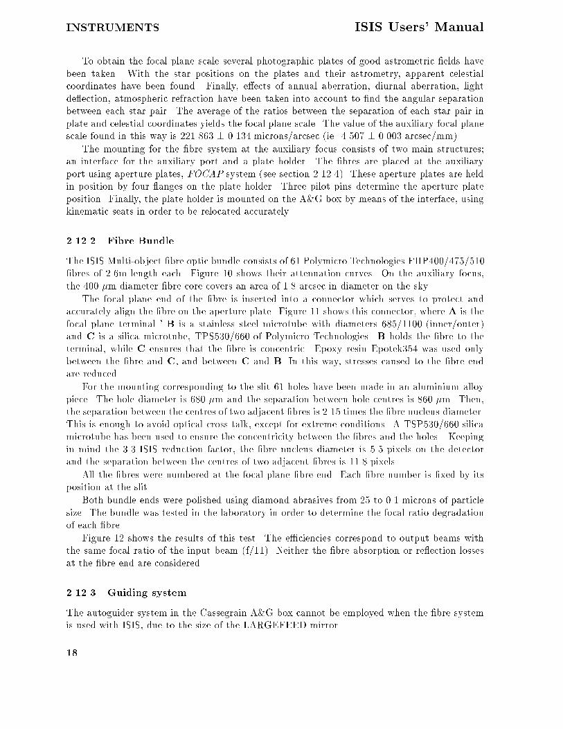
To obtain the focal plane scale several photographic plates of good astrometric �elds havebeen taken� With the star positions on the plates and their astrometry� apparent celestialcoordinates have been found� Finally� e�ects of annual aberration� diurnal aberration� lightde�ection� atmospheric refraction have been taken into account to �nd the angular separationbetween each star pair� The average of the ratios between the separation of each star pair inplate and celestial coordinates yields the focal plane scale� The value of the auxiliary focal planescale found in this way is ���� �� � ���� microns�arcsec �ie� ��� � ����� arcsec�mm��
The mounting for the �bre system at the auxiliary focus consists of two main structures�an interface for the auxiliary port and a plate holder� The �bres are placed at the auxiliaryport using aperture plates� FOCAP system �see section ������� These aperture plates are heldin position by four �anges on the plate holder� Three pilot pins determine the aperture plateposition� Finally� the plate holder is mounted on the A�G box by means of the interface� usingkinematic seats in order to be relocated accurately�
������ Fibre Bundle
The ISIS Multi�object �bre optic bundle consists of �� Polymicro Technologies FHP��������bres of ���m length each� Figure �� shows their attenuation curves� On the auxiliary focus�the �� �m diameter �bre core covers an area of �� arcsec in diameter on the sky�
The focal plane end of the �bre is inserted into a connector which serves to protect andaccurately align the �bre on the aperture plate� Figure �� shows this connector� where A is thefocal plane terminal � B is a stainless steel microtube with diameters � ����� �inner�outer�and C is a silica microtube� TPS������ of Polymicro Technologies� B holds the �bre to theterminal� while C ensures that the �bre is concentric� Epoxy resin Epotek� was used onlybetween the �bre and C� and between C and B� In this way� stresses caused to the �bre endare reduced�
For the mounting corresponding to the slit �� holes have been made in an aluminium alloypiece� The hole diameter is � � �m and the separation between hole centres is �� �m� Then�the separation between the centres of two adjacent �bres is ��� times the �bre nucleus diameter�This is enough to avoid optical cross talk� except for extreme conditions� A TSP������ silicamicrotube has been used to ensure the concentricity between the �bres and the holes � Keepingin mind the ��� ISIS reduction factor� the �bre nucleus diameter is � pixels on the detectorand the separation between the centres of two adjacent �bres is ��� pixels�
All the �bres were numbered at the focal plane �bre end� Each �bre number is �xed by itsposition at the slit�
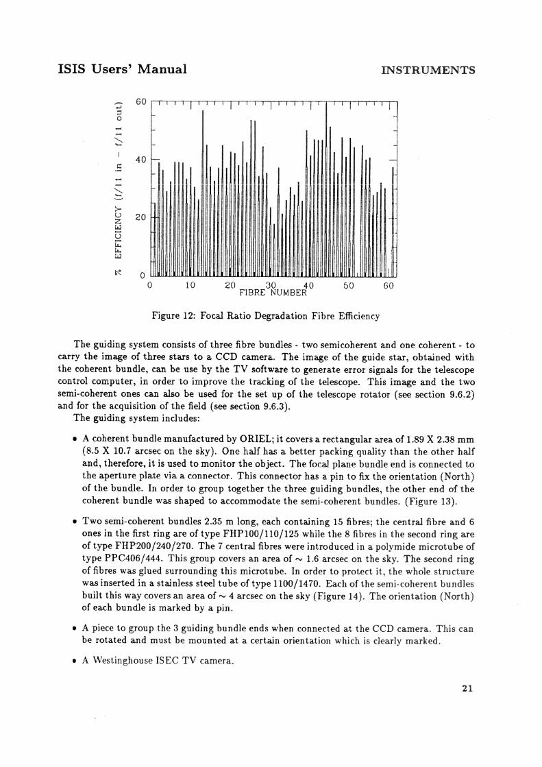
Both bundle ends were polished using diamond abrasives from � to ��� microns of particlesize� The bundle was tested in the laboratory in order to determine the focal ratio degradationof each �bre�
Figure �� shows the results of this test� The e�ciencies correspond to output beams withthe same focal ratio of the input beam �f����� Neither the �bre absorption or re�ection lossesat the �bre end are considered�
������ Guiding system�
The autoguider system in the Cassegrain A�G box cannot be employed when the �bre systemis used with ISIS� due to the size of the LARGEFEED mirror�
��


ISIS Users� Manual INSTRUMENTS
Table � Speci�cation of the holes to be drilled in the Aperture Plates
Object Position Drilling Position Drill diameter �mm�Single Fibre �x� y�� �x� y�� �����Semi�coherent bundle �x y� �x y� ����Semi�coherent bundle �pin� �x y������ ����Coherent bundle �x� y�� �x� y������� �����Coherent bundle �pin� �x� y�������� ����
� A lens relay system to produce the image of the guiding bundles on the detector�
� A Melles Griot mechanical system for the manual focussing of the guiding bundles
������ Aperture plates
For multi�object spectroscopy� the acquisition of the �eld is performed by means of an apertureplate of type FOCAP� This aperture plate is a �mm thick brass plate� The plate is drilled atprecise locations with holes to accept �bre connectors� The holes must be made for each of thethree types of connectors� for the individual �bres� for the two semi�coherent bundles and forthe coherent bundle� The characteristics of the holes are speci�ed in the Table �it is assumedthat the OY� direction corresponds to the North direction during the observing epoch��
The vertical displacement that the coherent bundle has with respect to the object coordinatesallows it to be observed by the northern part of the bundle� where the packing quality is best�see section ��������
A high precision �on the order of ���m� both for the coordinates and the hole diameters isfundamental for accurate �eld acquisition�
The number of holes to be performed for each type of connector is as follows�
� for individual �bres� � one hole for each target � one for each sky area to be sampled
� for the semi�coherent bundle� � one hole ��� North of the �eld centre �relative to observingepoch� � one ��� South of the �eld centre �relative to observing epoch� � one for eachguide star for manual guiding �two at least�
� for the coherent bundle� � one hole for the �eld centre � one for the guide stars chosen fortelescope tracking �one at least��
The aperture plates can be made by the CAMM� engraving machine� in the same way as themulti�slit masks� Observers wishing to use the �bre system should provide accurate co�ordinatesfor aperture plate manufacture to La Palma sta� at least one month in advance of the observingrun�
������ Observing coordinate determination�
The �X�Y� coordinates of the targets to be observed with multi�object spectroscopy� can beobtained in two ways�
��

INSTRUMENTS ISIS Users� Manual
� From the astrometry of the �eld� Transformation of the equatorial coordinates of thetargets onto the corresponding aperture plate coordinates �X�Y�� is performed with theLAPLATE programme� which is described in Appendix F and which is a modi�cation ofthe APLATE programme of the STARLINK package� for the geographical coordinates ofthe ORM� LAPLATE takes into account the following parameters� telescope focal planescale� thermal dilation coe�cient of the aperture plate material� astronomical coordinatesfor the centre of the �eld� and possible proper motions of the targets� These are allconsidered by the programme in order to obtain the appropriate corrections of the X�Ycoordinates�
� By taking photographic plates of the �eld in advance� The positions can be measured witha microdensitometer or other coordinate measuring machine�
Several error sources can contribute to the �eld acquisition� for example poor astrometry�the drilled holes for the stars do not coincide with the apparent positions� or bad centering ofthe �eld and rotator adjustment� Taking direct plates eliminates some sources of astrometricerror� at the expense of requiring extra observing time�
Besides the coordinates of the targets� at least three other �eld stars must be chosen fortelescope guiding� These stars must ful�l the following requirements�
� They must have magnitude �� to �� in V� Brighter stars are close to the Earth and canhave large proper motions� so that it is in general di�cult to obtain good astrometry ofthem� Less bright stars are di�cult to observe�
� They must have similar brightness� If not� simultaneous observation on the monitor couldbe prevented as the brightest ones can saturate the camera while the weakest remainunseen�
� They must be as separated from each other as possible in the �eld� and� preferably alongthe East�West direction which is free of atmospheric refraction� This helps in obtaining amore precise �eld acquisition�
Finally� some positions free of stars must also be chosen� in order to perform sky corrections�
������ Overall Performance
Geometrical losses� mainly caused by focal ratio degradation� give a mean e�ciency of around�� of the value when observing directly through the slit� Transmission losses in the �� metre�bre length are small� except shortward of ��� �A� between ���� and ��� �A� and longward of ��� �A� However acquisition is critical� and much larger losses can be produced if the astrometryis not better than �� arcsec for any reason� Some on�sky measurements� taken in ��� arcsecseeing� show that the total sensitivity of the system� is � photon�s��A at �� �A for a star ofB�� with the TEK� CCD on the blue arm� and ��� photon�s��A at ���� �A for a star of R��with the EEV� CCD on the red arm� There is a �bre�to��bre scatter of ��� in each of thesevalues�
The e�ciency is very sensitive to the acquisition procedure� a shift of � arcsec from thebest position loses about � of the light� and a shift of �� arcmin in the Cassegrain rotatorposition angle loses about �� of the light� although this latter �gure depends upon the radialdistribution of objects�
��

ISIS Users� Manual INSTRUMENTS
� Performance
��� Throughput
Nearly all of the light losses within ISIS are due to re�ective and air�glass surfaces� Thereis a small loss of light ������ in each camera due to optical vignetting� and for the highestdispersions there is some loss due to over�lling of the grating �see Appendix D�� The throughputof ISIS has been measured by C�R� Jenkins and P� Terry� and their results are discussed in detailin ING La Palma Technical Note no� ��� Brie�y the throughput of the red channel withoutthe grating is measured to be ��� and that of the blue channel without the grating to be ���These measurements were made with a HeNe laser at ���� �A� and thus for the blue arm areslightly beyond the wavelength range over which it is optimised� The values for the red arm arealso slightly low as the red fold mirror in use at the time was below its speci�cation�
The e�ciencies of the ISIS gratings have been measured in the laboratory and are presentedin Figure �� The holographic grating has a lower e�ciency than the ruled gratings� and is alsoused at a grating angle such that the beam over�lls the grating� resulting in some light loss�
The calculated peak e�ciency for FOS�II is ��� in �rst order at ���� �A� and �� in secondorder at ��� �A� The diagrams below show the calculated e�ciency as a function of wavelength�and the measured e�ciency of the entire system �including telescope� atmosphere and detector�as a function of wavelength
The e�ciency of the overall system is dependent upon the throughput of atmosphere� tele�scope and instrument� and the e�ciency of the detector� Measured values of the number ofphotons�AA�s detected for objects of accurately known magnitude are presented in Section ��
�� Stability and radial velocities
The original speci�cation for ISIS was to have �exure no more that �m�hour along and per�pendicular to the slit during telescope tracking� However measurements of the �exure caused bymovements in elevation� and movements of the instrument rotator� suggest that �exure duringtracking could be up to ��m�hour� The cause of the extra �exure is not yet known� and untilit is corrected it is recommended that observers requiring accurate radial velocities should takea calibration lamp exposure every � minutes�
Measurements of radial velocity standard stars taken during commissioning show that if careis taken with the calibration exposures it is possible to measure radial velocities to an r�m�s�accuracy in the range ��� km�s with the highest dispersion gratings �H���B and R����R� witheither arm of ISIS� The systematic o�set between ISIS radial velocities and the IAU velocitysystem is measured to be��
�VIAU � VISIS� � ��� ��km�s�
from blue arm observations of radial velocity standard stars and nebulae�The stability of FOS�II has been measured to be better than ��m�hour when tracking an
object through the zenith�
��� Scattered Light
Scattered light in ISIS is minimised by the use of optimised anti�re�ection coatings� and ifscattered light would be a serious problem for a particular observation it is important to exclude
��


INSTRUMENTS ISIS Users� Manual
light of wavelengths other than those required� particularly wavelengths outside the range forwhich the coatings are optimised� from the optics by use of appropriate colour �lters�
Di�use scattered light has be shown to be below �� by observations during commissioningof Quasar absorption lines known to be completely black�
Ghost images are caused by stray re�ections within the spectrograph� and can either bein�focus images or images of the pupil� Pupil images take the form of the telescope pupil withthe central obstruction� even if the illumination is from the comparison lamp system� becausethe illumination from the integrating sphere is designed to mimic exactly that of the telescope�This is not true of the comparison lamps for the �bre optic system�
There are a number of known ghosts in the ISIS system� these are listed below��
� A ghost spectrum parallel to the primary spectrum which is seen in blue arm observationswhen a dichroic �lter is used� It is caused by light re�ected o� the back surface instead ofthe front surface of the dichroic� It is strongest at wavelengths in the crossover region� Theo�set on the detector from the primary spectrum is ��� mm for the older �thin� dichroics�and ��� mm for the new �thick� dichroics�
� A Narcissus ghost pupil image which is caused by re�ection between the surface of theCCD or its surrounds and the cryostat window� This appears strongest when caused bystrong spectral features just o� of the CCD� for example when looking at a Copper�Argonsource at blue wavelengths at low dispersion� when the ghost is caused by re�ection of thestrong red lines from the surrounds of the CCD� If it is due to a continuum source thepupil image will be smeared in wavelength� and may be di�cult to recognise as such� Theintensity of this ghost is at the level of ���� of the primary source�
� A grating ghost caused by re�ection between the grating and the aspheric plate of thecamera when using grating R� R in the red camera� The ghosts images of all wavelengthsadd� so this ghost can appear quite strong�
� An in�focus ghost caused by a re�ection from the folding prism� in either the red arm ofISIS or in FOS�
� Rowland ghosts� which are caused by periodic errors in the ruling of the gratings� Theseappear around strong emission or comparison lines� as satellite lines at the level of �����
of the primary�
��� Wood�s Anomalies in the ISIS gratings
Wood�s anomalies are discussed in detail by P�G� Murdin in ING La Palma Technical Note No��� in the context of INT IDS gratings� and a summary of the physical explanation for Wood�sanomaly is repeated here�
Consider a re�ection grating which produces a range of di�racted light in successive ordersdi�racted away from the normal� In some order� at some critical wavelength� the di�racted lightlies in the plane of the grating� It is not possible for light beyond this point to be di�ractedbehind the glass of the grating� The power which would be sent into the forbidden region isredistributed back into the allowed orders� The power appears as an addition to the spectralresponse� with a sharp cut on at the critical wavelength and a steep decline to the red� Thisadditional e�ciency is almost entirely polarised perpendicular to the grating rulings�
��

ISIS Users� Manual INSTRUMENTS
Wood�s anomalies occur at wavelengths��
� � d�sin���� ���n
where d is the grating groove separation� � is the grating angle �the angle between the gratingnormal and the collimator axis�� and n is a positive or negative integer�
There are known to be Wood�s anomalies in ISIS at ���� �A ����� grating� n � ��� ��� �A���� grating� n � � and �� �A ���� grating� n � ����
��

DETECTORS ISIS Users� Manual
Part II
Detectors
� CCD Detectors
CCDs are widely used in astronomy� and are the major detectors for almost all of the instrumentsof the Isaac Newton Group� Descriptions of CCDs and their operation at a non�technical levelare given in a number of astronomical publications� two recent reviews have been given byC�D� Mackay in Annual Reviews of Astronomy and Astrophysics� volume �� page �� and byP�R� Jorden in Modern Technology and its In�uence on Astronomy� edited by J�V� Wall and A�Boksenberg� published by Cambridge University Press� page ����
��� Schematic view of the CCD systems
The CCD systems in use at the WHT are described by P�R� Jorden et al� in Proc� SPIE� Inbrief the CCD systems consist of the following components� ordered approximately by the datapath from detector to user�
� CCD chips contained in Oxford Instruments cryostats �the cryostats are painted brightred�� New chips and types of chips are frequently brought into use� but at the timeof writing the main chips in use at the WHT are GEC P ���� EEV P ��� and Tek���� The properties of these� and the next generation of CCD chips �the EEV P ���are tabulated below� New types of chips will be announced in Gemini as they becomeavailable� The Oxford Instruments cryostats contain liquid nitrogen� and the CCDs aremounted on a heated copper block� By controlling the current into the heating elements�and by sensing the chip temperature with a platinum resistor� it is possible to maintainthe CCD temperature at a preset value to an accuracy of about ����C� The value of thispreset temperature depends upon the CCD� and typical values for the CCD types are listedin the table below� The FOS�II CCD is mounted di�erently� in that the liquid nitrogenreservoir is much further from the CCD� and is connected to by a copper cold �nger�
� A preampli�er box� usually painted blue� which is mounted on the side of the cryostat�
� The compact CCD controller� designed by NFRA Dwingeloo� and described in detail byJ�D� Bregman and A� Doorduin in Proc� S�P�I�E�� volume ���� page ��� ������ and byJ�D� Bregman and N�R� Waltham in Proceedings of the ESOOHP workshop on The Optimisation of the use of CCD Detectors in Astronomy� p��� ������ and which is mounted inone of the electronics racks on the Cassegrain cable wrap� The compact controller containsthe following components��
A low heat dissipation power supply�
A CPU card containing an MC� �� microprocessor running a PROM based FORTHsystem�
A Temperature� shutter� and pre�ash control card for each CCD head controlled bythe controller�
Cards which provide and sequence the clock and bias voltages for each CCD�
��

ISIS Users� Manual DETECTORS
An analogue to digital converter card containing a �� bit analogue to digital converter�
A Correlated Double Sampler �CDS� board�
A �bre optic transmitter and multiplex control card�
A �oppy disc controller for FORTH software development�
A real time board with opto�isolated RS��� ports for communication with the UtilityNetwork and with terminals�
� A �bre optic cable run� with a number of connectors� passing through the cassegrain cablewrap� The �bre optic cables usually have a bright yellow sheath�
� The Fibre Optic Multiplexer �FOX� unit� containing the CCD Interface sequencer and oneCCD interface card for each controller� in the upper rack of the Detector Memory Systemcabinet in the control room� The CCD interface card includes a �bre optic receiver� whichdecodes the serial data from the optical �bre� and a �� by � bit FIFO bu�er into whichthe data is placed in parallel form� The Interface Sequencer card is responsible for readingdata from the CCD interface cards into the DICI card �see below�� There can be up to�� individual CCD interface cards in the rack� although there are not usually more thanthree� Each pixel� when read from the CCD interface card FIFO� has � bits� of which�� are data bits� and � are address bits� which ensure that the data arrive in the correctbu�er in the Detector Memory System� The CCD interface card has three lights on thefront� These are��
Data Available� a green light which indicates that data are available in the FIFO� andthe CCD controller is sending data�
FIFO Full� a yellow light which indicates that at some point the FIFO has been �lled�and CCD data have probably been lost�
G�O�A�T� a red light which indicates that CCD Interface card cannot detect thecarrier for the optical signal�
If either the yellow or red lights are showing on the relevant CCD interface card then thereis a problem�
� The Dual IPCS CCD Interface �DICI� card in the DMS rack�
� The Detector Memory System� This is described in brief in the next chapter�
�� CCD chips in current use at the WHT
The table below summarises the characteristics of the types of CCD chips in current use forall instruments at the WHT� Availability of CCDs changes frequently� and updates to thisinformation will be published regularly in Gemini� At the time of writing the CCDs available onthe two arms of ISIS are� EEV� and EEV� which are EEV P ���s� TEK� which is a Tektronix��� square� and GEC which is a GEC P ���� In the very near future EEV � an EEV P ��will become available� The CCD in FOS�II is currently a GEC P ����
There is a choice of two readout speeds for the CCDs� known as �normal and �quick � Itis possible to switch between these modes from the ICL interface with the commands SPEEDY
��

DETECTORS ISIS Users� Manual
Table �� CCD types available at the WHT �as of May �����
CCD Type Pixel CCD Format Image Format Read noise �e�� Dark Current Operating��m� �pixels� �pixels� normal �quick� e��hour Temp �K
EEV P����� � ����� �������� ��� ���� ������EEV P���� � ����� ������� ������GEC P���� �� ������ ������ ���� ��Tek ��� ��� ������� ������� � ��� ���
Table �� Recommended bias regions for WHT CCDs
CCD Type Recommended bias region in X Recommended bias region in Ypixels pixels
EEV P����� ��� ��������EEV P���� ��� ��������GEC P���� �� ������Tek ��� ����� ��������
�channelname� and SLOUCH �channelname�� which select quick and normal speed respec�tively� The advantages of quick speed are a faster readout �less overhead�� and a higher dynamicrange� The disadvantage is a higher readout noise �column � of the table above�� For each CCDthere is a distinct value of the gain�� the conversion factor between the output of the analogueto digital converter and the number of detected photoelectrons per pixel� for each readout speed�The values of gain�� usually expressed in e��adu� will be known to local sta��
All CCDs produce an image which is larger in both dimensions than the active area of theCCD� this area is given in column above� The additional image area consists of underscan andoverscan and dark reference regions� The di�erence between these types of reference regions� andthe location of the regions for CCD types in use on the WHT� are discussed by P�R� Jorden inING La Palma Technical Note no� ��� The bias level in each data frame� which is an electronico�set with a low frequency time dependence� is estimated most reliably from the serial underscanregion� in regions of the image frame which are given in the table below�
On�chip binning and windowing are available for any CCD� and the parameters can becontrolled using the ICL commands BIN and WINDOW� On�chip binning is useful not only inreducing the amount of data read out from the CCD� and thus the dead time between exposures�but also in reducing the e�ective readout noise in the data� Because the readout noise occursonly once for each summed pixel� the e�ective readout noise is reduced by the a factor of thesquare root of the number of pixels summed� On the other hand� because the output of theanalogue�to�digital converter limits the amount of charge that can be read from the CCD in anyone pixel� on�chip binning reduces the maximum dynamic range that the CCD can provide bythis same factor�
The Tektronix CCD� being thinned� has a higher Quantum E�ciency �QE� than the EEV andGEC CCDs� particularly at blue wavelengths� At far red wavelengths �� ����A� it does su�erfrom a degree of fringing�� which causes a modulation of sensitivity with amplitude ��� whichis very dependent on grating position� When using a thinned CCD at red wavelengths it is vital
��

ISIS Users� Manual DETECTORS
Figure ��� Quantum E�ciency of the CCD types available on the ISIS and FOS�II spectrographs�
to obtain and use �at�elds taken at precisely the same grating angle at the target observations�
� The CCD�IPCS Detector
�� Scienti�c Description
The photon�counting detector available on the blue arm of the ISIS spectrograph is the CCD�IPCS� It is fully described in The IPCS�II Users Manual by J�S�B� Dick�
The CCD�IPCS provides true photon counting with no readout noise� but has an importantlimit on the maximum photon count rate for a linear response� The present version was rebuiltin June ����� It has an S�� photocathode� a �stage EMI intensi�er image tube with phosphorsat the last stage� and as back end detector the rebuilt version has a thinned GEC CCD� Thislatter is slightly smaller than the original �an RCA CCD� so that slightly less spectrum isaccommodated� The back end CCD has ���m square pixels which can be subdivided into �� or sub�pixels in spectral or spatial directions� However� there is an internal demagni�cation�so that �e�ective� sizes at the photocathode are �� � larger� The maximum available area is ��� ��� pixels� In the spectral direction� with �� � subdivision there are ��� pixels each with ane�ective size of ����m� with no subdivision� there are ��� pixels of �m each� In the spatialdirection� no subdivision ������ yields ��� arcsec�pixel� and �� � gives ���� arcsec�pixel�
The CCD�IPCS resolution obtained depends very slightly on wavelength �worse to the blue��a resolution �FWHM� of ���m �i�e�� ��� pixels at �� �� is obtained at ����A�
Observers familiar with IPCS�I detectors� used at the AAT and on the INT� will �nd manythings in common between the systems� The principal di�erence is that the CCD�IPCS has aGEC CCD as back end detector� whereas IPCS�I has a Plumbicon TV tube� Also� IPCS�II has
��

DETECTORS ISIS Users� Manual
a linear response up to somewhat higher photon count rates than does IPCS�I �see below��
The maximum count rate per CCD pixel for a deviation from linearity less than ��� isdependent upon the frame size �higher maximum rate for a smaller frame�� and upon the dis�tribution in intensity of the source �higher maximum rate for emission line than continuumsources�� In tests with a prototype CCD�IPCS in �� � with full format ���� ��� CCD pixels�and frame time of ��ms� about � loss was found at a measured rate of � ct�s�CCDpixel� Ina �spectroscopic� format ��� ��� at �� � spectral resolution�� with a frame time of ms� lineratios showed no sign of nonlinearity at count rates up to � ct�s�CCDpixel� This correspondsto a rate of ���ct�s�channel at a spectral resolution �� � and spatial resolution �����
There are two real�time display screens showing the detection of photon events� On thetelescope the display is located next to the high�tension �EHT� controls so that the detectorcan be monitored as the EHT is brought up� The second display is in the control room� andhere the screen must be monitored carefully each time the IPCS shutter is opened�
The IPCS is easily damaged by bright light� and great care must always be taken using it� Forany new setup� new on�sky source or new calibration lamp� it is safest to include a large amountof neutral density �eg� ND��� in the beam and reduce it gradually� For comparison lamps� thiscan be achieved by putting ND��� in COMPFILTA and ND��� in COMPFILTB� For sky objects�you can do it by putting ND in the main beam �lter with the command MAINFILTND ND����
There is a red �Panic Button� and you should keep your �nger over this as you open the IPCSshutter each time on a new source of light� Operation of this button will close the IPCS shutterimmediately� but will not a�ect the EHT voltage� Two typical symptoms of a dangerously�highrate are� �a� the dots of light on the real�time CRT display merge to form a solid �splodge� oflight �which is not �ickering�� or �b� if the IPCS shutter is closed� the glow on the real�timedisplay takes more than �� secs to fade�
� CCD�IPCS granularity and Dithering
The CCD�IPCS has sensitivity variations over its �eld of view which are due to physical ir�regularities in the photocathodes inside the intensi�er�� The spatial variation in sensitivity isreferred to as �granularity� because of the grainy appearance it gives to images�
In order to reduce the e�ect of granularity due to last three stages of intensi�cation� a schemeof �dithering� was introduced for the IPCS�I �Jorden � Fordham Q�J�R�A�S�� �� ���� �� ���By moving the image around on the last three photocathodes in the intensi�er� the signal ina given pixel� averaged over time� is proportional to the mean sensitivity within the scannedarea� Hence� the pixel�to�pixel granularity is �typically� reduced by a factor of two� A similartechnique is used with the IPCS�II but this also counteracts the �xed pattern noise due to thecentroiding algorithm used in that detector� the granularity of the �rst photocathode is notdiminished by these techniques since the image on this photocathode cannot be scanned�
The e�ects of granularity may be reduced by dividing an acquired image by a �at��eld�so compensating for the pixel�to�pixel variations in sensitivity� The exposure required for a�correct� �at��eld depends on the spatial scale of both the granularity and the informationcontent within an image� Jenkins �MNRAS� ���� ��� �� �� analysed granularity using Fouriertechniques and showed that most of the power is on scales of many pixels ���� little power wasseen on small scales �� pixels��
Flat��elding is� therefore� highly desirable when the noise in the data due to photon noise isless than the power density of the granularity at the spatial frequencies of interest� To adequately
��
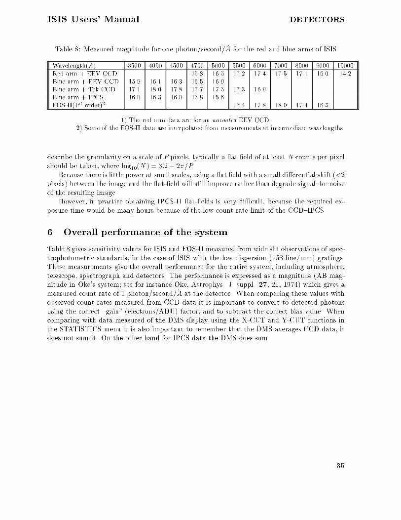
ISIS Users� Manual DETECTORS
Table � Measured magnitude for one photon�second��A for the red and blue arms of ISIS
Wavelength��A� ��� ���� ��� ���� ��� �� ���� ���� ���� ���� �����Red arm � EEV CCD� ��� ��� ��� ���� ��� ���� ���� ���Blue arm � EEV CCD ��� ���� ���� ��� ����Blue arm � Tek CCD ���� ���� ���� ���� ��� ���� ����Blue arm � IPCS ���� ���� ���� ��� ���FOS�II��st order�� ���� ���� ���� ���� ����
�� The red arm data are for an uncoated EEV CCD�� Some of the FOS�II data are interpolated from measurements at intermediate wavelengths�
describe the granularity on a scale of P pixels� typically a �at �eld of at least N counts per pixelshould be taken� where log���N� � ��� � ���P �
Because there is little power at small scales� using a �at �eld with a small di�erential shift ���pixels� between the image and the �at��eld will still improve rather than degrade signal�to�noiseof the resulting image�
However� in practice obtaining IPCS�II �at��elds is very di�cult� because the required ex�posure time would be many hours because of the low count rate limit of the CCD�IPCS�
Overall performance of the system
Table gives sensitivity values for ISIS and FOS�II measured from wide slit observations of spec�trophotometric standards� in the case of ISIS with the low dispersion �� line�mm� gratings�These measurements give the overall performance for the entire system� including atmosphere�telescope� spectrograph and detectors� The performance is expressed as a magnitude �AB mag�nitude in Oke�s system� see for instance Oke� Astrophys� J� suppl� �� ��� ���� which gives ameasured count rate of � photon�second��A at the detector� When comparing these values withobserved count rates measured from CCD data it is important to convert to detected photonsusing the correct gain� �electrons�ADU� factor� and to subtract the correct bias value� Whencomparing with data measured of the DMS display using the X�CUT and Y�CUT functions inthe STATISTICS menu it is also important to remember that the DMS averages CCD data� itdoes not sum it� On the other hand for IPCS data the DMS does sum�
��

COMPUTERS ISIS Users� Manual
Part III
Computers and Operations
Control System
��� Control system overview
The main elements of the control system are shown in Fig� � � ISIS mechanisms are controlledby the observer typing commands at the ICL instrument control interface� The ICL interfaceruns on the system computer �currently a Vax ��� called LPVF�� and the display is via theObserver�s Vaxstation ���� �LPVS��� ICL commands are typically procedures containing lower�level commands to d�tasks �device tasks� which are high�level �PASCAL� programs running onthe system computer �LPVF� as sub�processes of the main observer�s process� There are d�tasksfor each of the major mechanisms e�g� ISIS� A�G� UES� telescope� DMS� each CCD� The d�tasksin turn exchange messages over the utility network Ethernet with the Motorola microprocessorscontrolling individual stepper�drive motors� barcode readers and shutter modules� The messagesare typically commands to move� status requests and status returns�
Most of the mechanisms are controlled via Motorola � �� �locally known as �MS�� micro�processors� there is one for each of ISIS� A�G� FOS� LDSS� TAURUS� UES and IPCS� The TV�autoguider and Detector Memory System �DMS� each use a � ��� processor in a VME chassis�housed in the blue control cabinets�� The CCD controllers �including that for the autoguiderCCD� are based on � �� microprocessors� The microprocessors are programmed in FORTH�Each of the microprocessors� and the system computer� is connected to the utility network viaa Network Interface Unit �NIU�� Each NIU can connect up to four microprocessors� There arecurrently two NIUs on the telescope and two in the control room� Data from the CCDs is trans�mitted via �bre�optic links to the autoguider and DMS VME systems� Data arriving at the DMSare automatically sent to the data disk on the system computer and may also be transferred tothe SPARCstation �currently LPSS��� The integrating TV system is currently stand�alone andcannot be controlled across the Utility Network� If the ICL�d�task control route fails for somereason� mechanisms can often be controlled more directly from the engineering terminals in thecontrol room� by keying in messages to be sent over the utility network� At a still�lower level�duty tecnicians can plug a terminal directly into a microprocessor on the telescope and sendcommands from there�
LPVF is linked via DECNET� running over a separate Ethernet� to the telescope�controlcomputer �a microVAX�II� currently LPVB�� to the VAXstation running the user interface� toother VAX ��� computers on a DEC cluster� to the DECservers serving terminals and printers�and to SPARCstations on a SPARC cluster� Separate Ethernets at the INT and JKT areconnected to the WHT ethernet via �bre�optic links�
The DMS and several of the VAXes and SPARCstations can be used for data reduction�The DMS provides a few simple analysis functions e�g� cuts� statistics� FIGARO and otherreduction packages are available on the VAX clusters on both the mountaintop and at sea level�IRAF and SAOIMAGE can be run on the SPARCstation on the control desk �Section �����
Telescope control is e�ected via commands issued to the control system running on thetelescope�control computer� which is interfaced to the telescope mechanisms via CAMAC� Mosttelescope�control commands can be issued from the ICL interface and it is intended that in
��

ISIS Users� Manual COMPUTERS
the future the distinction between operator control of the telescope and observer control of theinstrument will blur�
Most of the information needed by the observer about the status of the system is included inthe telescope�control information display� the instrument�control MIMIC and the white�board�The MIMIC is discussed in Section ��� below� it displays information contained in the �notice�boards� which are continually updated by the d�tasks as a result of the commands and statusreturns they receive� Ephemeral information which is not �yet� held on�line e�g� contents of �lterslides� gratings loaded� CCD locations� is usually recorded on the whiteboard in the control room�There is some overlap between the information held on�line and that written on the whiteboard�Some useful instrumental information �e�g� focus o�sets� is recorded in the telescope logbook�
�� The Detector Memory System
The Detector Memory System allows detector data to be collected� displayed and transferred tothe system computer� A detailed description of the system is given by Johnson ���� �Electronicsreport ���� the Detector Memory System��
The DMS is a purpose�built computer� based upon a Motorola � ��� microprocessor� witha large area of memory ��� Mbytes� for storage of detector data� The system design is basedon the industry�standard VME architecture� There is a high speed data interface �DICI� DualIPCS CCD Interface� between the detectors and the VME memory� The system also has animage display facility� based on an Opal Graphics Controller�
Immediately after each exposure the data from all detectors appears in memory in theDetector Memory System �DMS�� Images obtained with CCD detectors are read out into theDMS at the end of an exposure� Photon counts from the IPCS�� are continually transferred tothe DMS during an exposure� where they are built up into an image�
The DMS is capable of handling multiple detectors simultaneously� reading the data fromdi�erent detectors into di�erent areas of memory �normally referred to as bu�ers�� This featureis particularly important for the operation of ISIS�
��� The SPARCstation
Data collected by the Detector Memory System �DMS� may be saved to the SPARCstation ��currently LPSS�� for examination using SAOIMAGE or IRAF applications�The Sparcstationis intended to meet the need for very rapid on�line evaluation of data� using standard reductionsoftware� The system consists of a Sparcstation �� with � Mbyte of memory and � Gbyte oflocal disk storage� connected to the DMS via a commercial S�bus to VME adapter� This allowsvery rapid transfer of data from the DMS to the SPARCstation�
The run number of the saved data is the same as that used on the VAX� At present� the dataare transferred without headers� Data may be written from the SPARC to an exabyte in TARformat� or FITS format� from IRAF� Instructions on starting up the SPARC and on using thevarious applications are kept in the control room� Image�examination routines run much fasteron the SPARC than on the VAXes�
IPCS data can be saved to the SPARC while the exposure is building up�The windows typically open on the SPARC are�
� DMS�SPARC interface� used to save data from any of � DMS bu�ers to the SPARC� andalso to obtain statistics on any of the images in the bu�ers �size� min� max and SD��
�


ISIS Users� Manual COMPUTERS
� SAOIMAGE� used for display and mouse�controlled examination of the image�
� IRAF command language� used for running other applications e�g� imexamine�
� IRAF �Tek�� used for displaying line graphics�
� Console window� where UNIX error messages appear�
� DMS control
The interface for transferring data from DMS memory to the Sparcstation local disks iscontrolled graphically on the Sparcstation itself� To transfer a speci�c bu�er to the Sparcstationthe user simply moves the pointer to the name or number of that bu�er� selects it with themouse� then selects with the mouse the SAVE option in the interface window� An IRAF format�le is then created in a scratch area on one of the Sparcstation discs� and the name of the �lecreated is displayed in the interface window� At present no header information at all is storedwith the data �les� The images can then be displayed in the SAOIMAGE window with theIRAF command display�
IRAF contains many facilities for rapid analysis of data of all types� users who requirespecialised facilities are advised to refer to the KPNO user manuals and cook�books� whichare kept in dark blue loose leaved binders in the control room� For quick�look analysis ofimages and simple spectroscopic data the IRAF command imexamine has many of the requiredfacilities� Typing help �commandname� at the IRAF interface produces a detailed descriptionof the command� and typing help �commandname� � lpr will produce a hard copy of the help�le on the Sparc laser printer�
By the end of ����� the DMS display functions should have been transferred to the SPARC�making the DMS monitor super�uous� Header examination and FITSOUT from the SPARCshould also be available�
The mountain�top SPARC cluster currently includes � SPARCs� � exabyte and a laser printer�There is a SPARC plus exabyte in each telescope building�
��� The Utility Network
The Utility Network is a local Ethernet� running between the various focal stations of theWHT� and the control room� over which the microprocessor systems �the ms systems whichcontrol the instruments and the Engineering Mimic� the VME computers which control theAutoguider� and the DMS� and the CCD controllers� communicate� Each device communicatesvia a Network Interface Unit �NIU�� and each NIU can connect up to devices to the Ethernetlink� The system computer is also connected to the Utility Network via an NIU� this allowsthe transmission of messages from the User Interface to the devices� The Utility NetworkEthernet is physically separate from the Ethernet which connects the Vaxcluster and variousother computers around the site� Utility Network messages conform to a local protocol setout in Johnson ���� �Electronics report ��� ��m WHT Utility Network� Instrument ControlRecommendations��
�� The System Computer and User Interface
The system computer has two principal roles as part of the data�acquisition system�
��

COMPUTERS ISIS Users� Manual
� The system computer� running the ADAM control system� is responsible for coordinatingthe entire data acquisition process� The commands for doing this are listed in Part VI�
� The data acquisition system writes the data to �les on the system computer datadisk�ready to be archived�
On completion of an exposure� the data is normally transferred from the DMS to the systemcomputer� via a DR���W interface� The header information associated with that data willhave been collected by the system computer� either during the exposure� or on completion ofthe exposure� Data and headers are then merged into a data�le on the system computer disk�The data�le is in HDS NDF format� the header information being stored in the standard FITSextension to this format� Finally� two copies of the data are written to tape� a FITS format tapefor the La Palma archive� and either a FITS tape or a VAX backup tape for the observer�
The system computer is networked to various data reduction computers �currently a VAX��� plus several VAXstations�� Data can be copied across to these machines for immediateprocessing�
��� The MIMIC display
The MIMIC display running on the VAXstation ���� gives mainly�graphical representations ofthe current status of the telescope� instruments and detectors� There are a number of pages�which can be selected using the mouse� Current pages include�
� TELESCOPE� Current position on sky� airmass� parallactic angle� etc�
� CAGB� Light path and status of mechanisms in the A�G box only�
� ISIS SUMMARY� Light paths and status of mechanisms in the acquisition and guidanceunit� slit area and spectrograph� including TV� comparison lamps� autoguider� main �lters�auxiliary�port �lters� dekker slide� slit unit� above� and below�slit polarimetry modules�ISIS �lters� Hartmann shutters� collimators� gratings and detectors�
� CCDs� Focal station� chip name� size� windows� binning� temperature �and di�erencefrom nominal�� readout speed� exposure status� shutter status� requested exposure time�exposed time� UT start� for each CCD�
� CCDs SUMMARY� Temperature� exposure times� times to go� windows for each CCD�
� IPCS� Status of the IPCS
� IPCS�WINDOW� Size and position of the IPCS window�
A small version of the CCD summary page is permanently displayed� There are in additionindividual pages for CAGB� AUTOguider� ISIS SLIT and FOS� but the information from thesehas been incorporated into the ISIS SUMMARY page�
The current state of any mechanism or light path is identi�ed by its represented colouron the MIMIC screen� The colour scheme is�
��

ISIS Users� Manual COMPUTERS
WHITE mechanism is ok although not in use
RED mechanism is in error
BLUE mechanism is moving
GREEN mechanism is successfully in use
YELLOW the current selected light�path
The following ICL commands relate to the MIMIC �they are only normally needed whenproblems occur��
MIMIC PAGES List names of available MIMIC pages �screens�
MIMIC UPDATE Refresh current screen if it seems out of date
MIMIC START Start�up� Normally done in START�UP in ICL
MIMIC STOP Close down� Normally done in the ICL EXIT command
SCREEN Select a screen �e�g�� ISIS�� Normally done with the mouse�
��� Generating Data Tapes
ING telescope data are recorded to disk in �NDF format� and to tape in FITS format� Thepreferred medium is Digital Audio Tape �DAT�� the second choice is Exabyte tape� It is theresponsibility of the observer� or the support astronomer if present� to generate the archive tape�D�tape�� and operations sta� will normally provide a copy tape �C�tape� in FITS format on��track tape� Exabyte or DAT at the request of the observer� Alternatively the observer cancreate his or her own copy of the data in FITS format� or with the VMS BACKUP utility� onany of these media�
D�tapes can be created on any Vax in the cluster which has access to the required storagedevice� but the normal procedure is to do this on the main data reduction Vax LPVE� Theobserver should log onto this machine in the OBSERVER account� mount the tape on therequired drive� then use the utilities FITSINIT and WRITE FITS� which are described in Part VIto create the D�tape� A Tape Copy request form should then be �lled out� indicating what kindof C�tape is required�
��� Engineering terminals
In addition to the DMS and the Autoguider terminals� which are located on the control desk�there are three other terminals which allow access to various subsystems� These are located ona table behind the data reduction vaxstation �LPVS��� and close to the door which leads to thedome area� One of the three terminals is a network monitor which should only be used by LaPalma technical sta�� Use of the other terminals is normally restricted to technical sta� andsupport astronomers� and with the increasing reliability of the Vax control system� should occuronly rarely�
��

COMPUTERS ISIS Users� Manual
���� The Engineering MIMIC
The Engineering MIMIC is a ms computer which is used to run a schematic display representingthe status of ISIS and the A�G box� There are three diagrammatic pages� representing the A�Gbox� the ISIS slit are� and the rest of ISIS� Commands are available to switch between thesedisplay pages� to examine a particular mechanism in detail� and to move mechanisms in theseand other subsystems by issuing network commands� These are detailed in a guide called TheWHT Engineering MIMIC�� a pale green loosely bound document of which there should be atleast one copy in the control room� To use the engineering mimic select MIMIC on the rotaryswitch labelled A��
���� Direct control of the Cassegrain Instruments
It is possible to communicate with any of a number of other ms microprocessors using terminalA� by selecting the appropriate position on the rotary switch marked A�� The microprocessorsinclude��
� The FOS ms microprocessor�
� The ISIS ms microprocessor �position labelled CASS INST���
� The A�G box ms microprocessor�
� The IPCS ms microprocessor�
The last three should only be used by technical sta� who have read the appropriate technicaldocumentation� but until the FOS D�task has been fully commissioned it may be necessary tomove some FOS mechanisms and interrogate the status of the mechanisms from this terminal�These commands are listed in Part VI�
���� The Detector engineering control terminal
The Detector engineering control terminal can be used to communicate with one of the CCDcontrollers� including the autoguider CCD controllers� A limited number of CCD commands�used for assessing the performance of the CCDs and for taking test exposures when the Vax��� system computer is not available� are available to users and are documented in Section ����of this manual�
��

ISIS Users� Manual SETUP PROCEDURES
Part IV
SETUP AND OBSERVING
PROCEDURES
� Setup Procedures
��� Starting the computer systems
The mechanisms of ISIS and the A�G box� and the detectors� are under the control of a numberof microprocessors which communicate with each other and with the Vax ��� system computervia the Utility network� The primary interface from the user is a command language calledICL which runs on the Vax ���� and the primary source of information for the user is theMimic display� which is a graphical process running on the Microvax ��� but displaying on aVaxstation� usually a Vaxstation ����� which runs DECWINDOWS MOTIF� which is a variantof X�Windows� In order to display the data in real time� and in order to control the Autoguiderand DMS� it is necessary to run the Sparcstation �called lpss��� which is located to the left of theVaxstation� The Sparcstation also runs MOTIF� but this is a slightly di�erent implementationfrom that on the Vaxstation� The other important interface for the user is the Detector MemorySystem �DMS�� running Imageforth�� K� which provides a display of the data and a number ofsetup routines� This section describes how to check that all of the necessary systems are runningand are communicating over the utility network� and to get the user interfaces running�
Because the DMS local control does not run through terminals� but through a window onthe Sparcstation� the observer account on the Sparcstation should be started up �rst� On theSparcstation �lpss�� logon as observer� the password will be known to local support sta��Note that the Sparcstation runs the UNIX operating system� which is case sensitive� and allcommands typed in including usernames and passwords must be in the correct case� MOTIF willstart automatically� but the application to control the DMS must be started individually fromthe Applications menu� !From the Applications menu start the following applications��
� IRAF�DMS � This application will start the SAOIMAGE display server� a terminalwindow running IRAF� and the graphical tool for controlling data transfer from the DMSto the Sparcstation� It is advisable to start this application �rst�
� DMS WINDOW � This application will start a terminal window for local control of theDetector Memory System� this is also a FORTH system� so should also respond ok� if itis running�
Next� it is important to check that the Vax ��� and the DMS are running� The Vax ���is at the far end of the control room from the control desk� and is clearly labelled� The operatorconsole for the Vax ��� is near the computer� and it will be fairly clear from the paper outputof this whether the computer is running� The DMS is in a VME rack in the second of the fourblue cabinets to the left of the control desk� Its user interface consists of a terminal� mouse�and display screen towards the left hand end of the control desk� If the DMS appears not to berunning� or to be running in a non�standard con�guration� or you are unsure of the con�guration�toggle the switch labelled RESET on the module labelled VMPU of the DMS� The display
��

SETUP PROCEDURES ISIS Users� Manual
Table �� Microprocessors on the Utility Network
DMS The detector memory system itselfFOS The �ms microprocessor controlling the Faint Object SpectrographAGCA The �ms microprocessor controlling the Cassegrain A�G BoxISIS The �ms microprocessor controlling the ISIS SpectrographTAUR The �ms microprocessor controlling the Taurus Fabry�PerotUES The �ms microprocessor controlling the Utrecht Echelle SpectrographLDSS The �ms microprocessor controlling the Low�Dispersion Survey SpectrographCCD� The spare CCD controllerCCD� The controller for the Red Arm CCDCCD The controller for the Blue Arm CCDCCD� The controller for the FOS CCDCCD� The controller for the UES CCDIPCS The �ms microprocessor controlling the Image Photon Counting SystemAUT� The VME microprocessor controlling the CCD AutoguiderSYS The Vax ���� System ComputerENGM The Engineering Mimic which is a �ms microprocessor
screen will refresh� and the control window on the Sparcstation will display a system message�then leave a standard Forth prompt � ok� and a carriage return��
When the DMS is running it is possible to check which other subsystems are communicatingover the Utility Network� At the DMS control window type��
�NET
The DMS will then attempt to communicate with each of the subsystems in turn� and aftereach attempt will report either��
NO RESPONSE FROM �DEVICE�
or��
Acknowledgement received from �DEVICE��
The devices are��
If the DMS does not receive an acknowledgement even from itself there is most likely a faultwith the Network Interface Unit �NIU� connecting the DMS to the Utility network� or with thecables between the DMS and the NIU� If the DMS receives acknowledgements only from thosedevices which are connected to the same NIU as the DMS� then there is most likely a fault in
��

ISIS Users� Manual SETUP PROCEDURES
the connection between that NIU and the Utility network Ethernet cable�If any of the ms or VME microprocessors fail to respond� then it is most likely that they are
either not running� or are not correctly cabelled to the NIUs� If a group of devices on the sameNIU fails to respond then there may be a fault with that NIU� or the cables between that NIUand the utility network� NIUs have a recessed reset button at the rear� which can be pressedwith the sharp end of a pencil�
If the System Computer fails to respond� then it is possible to restart the Utility Networksoftware running on the Microvax� At the Operator�s console log in to the captive accountUNET� the password should be available near the console� This will stop and restart theUtility Network software on the Vax ����
If these simple remedies do not work then technical assistance should be sought� To run theobserving and data taking system the minimum con�guration is DMS� AGCA� ISIS� SYS� FOSif it is to be used� and whichever detectors are to be used� It is also convenient to have AUT�and ENGM communicating via the network�
Once it has been established that the relevant devices are communicating over the networkthe user interface to the System computer can be started� The user interface is usually run onthe Vaxstation located on the control desk� though it can be run on a spare Vaxstation elsewherein the control room� or the alphanumeric interface can be run on a terminal with the MIMICbeing displayed on a Vaxstation�
If using a Vaxstation for alphanumeric input the user should �rst log on to this Vaxstationas OBSERVER� The password will be known to local sta�� On the Vaxstation type��
LPVF
This is de�ned as SET HOST�LOG LPVF and a logon message from the Vax ��� systemcomputer will appear� The user should also log on to this computer as OBSERVER� Thepassword is the same� If using a terminal for alphanumeric input the user should log straightonto this machine� The system computer will display various information about new softwareand about the system� Two items require particular attention��
� The system will try to allocate the device XAA�� which is used for data transfer fromthe DMS� If it cannot do this it will display a message to this e�ect� this is usually becausethere is a terminal somewhere with observer logged on� In this case this XAA�� must bedeallocated at that terminal� or the process logged out or deleted� Then XAA�� must beallocated at the observer�s terminal�
� The system will display the amount of free disk space on the system and data disks� Ifthe data disk is full some data from previous night should be deleted� after �rst checkingthat it has been backed up�
At the Vaxstation or terminal type��
ICL
��

SETUP PROCEDURES ISIS Users� Manual
The ICL command language will start and the procedures and command de�nitions will beloaded� The user will then be invited to start the control tasks� to do this type��
STARTUP
The user is then given the option of running up the tasks or not� the answer to this question isalways YES� The user will also be asked which Vaxstation to run the MIMIC on� this is normallythe same Vaxstation as is being used for alphanumeric input� although it can be the other one�
The user is then prompted for the con�guration required� normally this will be one of thefollowing options��
� ISIS � A�G � CCDs
� ISIS � A�G � CCDs � IPCS
� ISIS � A�G � FOS � CCDs
The D�tasks will the be started and the various subsystems initialised� If the initialisationof one subsystem fails it is possible that other subsystems will not be initialised� if this appearsto be the case the subsystems can be initialised explicitly with the commands ISIS BEGIN�DMS BEGIN� CAGB BEGIN� DCT BEGIN� FOS BEGIN� AUT BEGIN and CCDINIT �ccdname��
Starting up ICL will also start up the telescope control system on the Microvax II telescopecontrol computer�
�� Con�guration of the A�G Box and Spectrograph
Gratings and other optical components must only be changed when the telescope isparked at the zenith� and whilst the change is being made an entry must be made
in the telescope log to the e�ect that the telescope is not to be moved until thework on the spectrograph or A�G box is �nished�
����� Changing Gratings
Although it is possible to change gratings without the ICL interface running this procedure israther involved� and should only be performed with the advice of technical sta�� With the ICLinterface running the procedure is fairly straightforward�
The grating angle or angles must �rst be moved to the change position� in this position thegrating cell is parallel to the back of the spectrograph� and to the access doors� and the gratingscan be removed from their cells and lifted straight through the access doors� An interlockprevents the grating cells being unclamped with the gratings at any other angle�
The procedure for changing gratings is invoked by typing��
CHANGE
at the ICL interface� A list of items which can be changed with this procedure is given� therelevant grating should be selected� The user will then be o�ered access to the spectrograph� if
��

ISIS Users� Manual SETUP PROCEDURES
the response to this question is YES� then the selected grating will be moved to the changeposition �grating angle ����� and both grating doors will be unlocked�
It is now possible to open the grating doors� which are located on the face of the spectrographopposite the long arm� The door for the blue grating is in the upper left hand corner of this face�and the door for the red grating is in the lower right hand corner� When the door is opened thegrating should lie approximately parallel to this spectrograph face� with the handles towardsthe door�
The grating clamps are operated by nitrogen pressure� and are activated by a toggle switch�For the red grating the switch is situated above the grating cell� and for the blue grating belowthe grating cell� If this toggle switch is moved to the down position the grating clamps willrelease� this should only be done with the telescope at the zenith� and the user should keep onehand on one of the handles on the grating itself while releasing the clamps� The grating canthen be withdrawn from the cell� and taken out of the spectrograph� All except the tallest ofobservers should use a set of steps while changing the blue grating� its cell is both higher o� theground and deeper inside the spectrograph than that of the red grating�
Gratings are normally kept in wooden boxes in a metal storage cabinet on the observing�oor� The boxes are clearly labelled with the identi�er of the grating they contain� The gratingsshould be kept in these boxes whenever they are not in use� and under no circumstances shouldthey be left out on the observing �oor� Users should never touch the surface of a grating�Any blemishes on the surface should be reported to the telescope manager� users should neverattempt to clean them o��
Replacing a grating in the cell is the reverse of removing one� ISIS gratings are always usedblaze�to�collimator� so the arrow showing the direction of the blaze angle should always pointtowards the centre of the spectrograph� The writing on the grating should be the right way upif it is in the red cell� and upside down if it is in the blue cell� The grating should be placed inthe cell� ensuring that it is properly seated� The toggle switch should then be moved to the upposition� the clamps will come on� If the clamps release immediately after coming on� then thegrating is not properly seated�
After the change is completed the user should press the return key at the ICL interface� Thegrating doors will then be locked� provided that they are closed correctly� The user should thentype in the name of the grating loaded in response to the question� The ISIS database will thenbe updated� and the name of the grating loaded should appear on the mimic� It is importantthat the correct grating identi�cation is loaded in the database� otherwise the procedure CENWAVEwill not work correctly�
Users should never rely on the information contained in the database� nor thaton the whiteboard in the control room� being correct when they �rst take over the
system� The database could be incorrect if a di�erent version of the software hasbeen in use� as di�erent versions of the software have separate databases� The only
way to check that the correct grating is loaded is to run the change procedure� openthe grating door� and look�
����� Changing Filters in the Main �A�G box� slides
The main neutral density and colour �lters are held in two �position slides in the lower sectionof the A�G box� To change a �lter within these slides the �lter should already be mounted ina holder� which can be obtained from RGO technical sta��
�

SETUP PROCEDURES ISIS Users� Manual
To access one of the �lter slides the slide to be accessed should be moved to position zero�out of the beam�� and the other slide should be moved into the beam� For instance to access a�lter in the COLOUR slide type��
MAINFILTC OUT
MAINFILTND �
The access door on the A�G Box can then be unlocked with��
AGACCESS�
This command will unlock the access door and will not return control to ICL until the dooris locked again� The door is on the lower half of the A�G box� and has a shiny metal latchwhich can be opened manually� To remove the �lter slide from the drive shaft a �mm Allenkey will be required� With the access door open an Allen screw can be seen in the centre of arectangular latch which holds the �lter slide in place� This screw should be removed and therectangular latch can be swung aside� to allow the �lter slide to be withdrawn from the A�Gunit� The �lter holders can then be interchanged using the same Allen key� The slide can thenbe inserted� the latch and Allen screw replaced� The access door can then be closed and latched�The AGACCESS procedure should then return an ICL prompt� and the interlocks should thenbe released� However the microswitch which detects that the door is closed does not alwaysoperate� and it may be necessary to open and close the door again until it does�
����� Changing components in the slit area
The slit area contains the dekker slide� the dichroic and folding �at slide� and the four ISIS �lterslides �two in the blue beam after the blue fold� and two in the red and FOS beams between theblue and red folds� Slides not in use are kept in a steel cupboard behind the WHT engineeringconsole� or else in the grating cupboard on the observing �oor�
Care must be taken when working in the slit area because it is possible to knock the slit jawsout of alignment� To realign the slit jaws it is necessary to remove ISIS from the telescope� andthis is equivalent to an extra instrument change� The slit area access door is interlocked withthe dekker slide� it is only possible to open the slit door when the dekker is in position �� whenit o�ers some protection to the slit unit� However with the door open it is then possible to movethe dekker away from position �� and it would then be easy to disturb the slit alignment� Usersmust not do this� and if they require any mechanism moved when the slit access
door is open they must contact RGO technical sta�� If the IPCS EHT supply is on thenonly a minimum of light can be used in the slit area with the door open� and in the dark it ismore likely that mechanisms will be disturbed by accident� Under these circumstances usersmust either switch the IPCS EHT to standby� or else contact RGO technical sta� for assistancebefore opening the slit door�
Before the slit door is opened the dekker slide must be in position �� At the ICL interfacetype��
DEKKER �
��

ISIS Users� Manual SETUP PROCEDURES
wait for the dekker action to complete� this mechanism is slow�
SLIT DOOR OPEN�
The slit access door can then be opened manually� The dekker slide is a horizontal slide atthe top of the slit area� which can be withdrawn from an angled groove� When replacing thedekker slide care must be taken to locate the slide correctly in this groove�
The two blue beam �lter slides are to the right of the slit area� and can also be withdrawnand replaced� However the grooves that the two slides run in are not identical and these slidescannot be interchanged� The same is true of the two red beam slides which are in the lowerpart of the slit area� All the �lter slides are somewhat sti�� and changing these �lters shouldnormally be done by RGO technical sta��
The dichroic slide is in the centre of the slit area� and is rather larger than the �lter slides�It contains the mounting cells for the dichroics and for the �at mirror� these have the shape ofa right angled triangle� The dichroic slide is held in place by a sprung loaded locator pin� thiscan be released by lifting the plastic knob on the slide� The knob can be twisted through ��degrees� when the locator pin will be held out� and the slide can then be withdrawn carefullythrough the slit access door� When the slide is replaced the user must ensure that the locatorpin is correctly engaged�
The slit door should be closed and latched� and is then locked by the command��
SLIT DOOR CLOSE�
The procedure CHANGE has been written to take the user through the process of changing thebelow slit �lters� The procedure will move the dekker to position �� unlock the slit door� andwhen the change has been completed will lock the door and update the database�
����� Directing light to the right cameras
The light path is shown on the CAGB� ISIS� and ISIS SLIT screens of the Mimic display� Thespectrograph can be con�gured for any combination of channels with the ISIS CONFIG com�mand� or the folding mirrors moved explicitly with BFOLD and RFOLD� To get light from thecomparison lamps to the cameras the user must ensure that the ACQCOMP mirror is in placein the A�G box� that nothing else is between the mirror and the slit �particularly that the LidCover is open�� that a comparison lamp is on� and if the IPCS is in use that an appropriateneutral density �lter is in the comparison beam� A typical sequence of commands is��
ISIS CONFIG BLUEANDRED Both blue and red channelsAGMIRROR ACQCOMP
COMPLAMPS CUAR Copper�Argon LampCOMPFILTA ND��� If the IPCS is in useCOMPFILTB ND�� If the IPCS is in useLID OPEN
It may be necessary to move any of MAINFILTND� MAINFILTC� FLENS CALC POL�HW POLAR� QW POLAR� ANAMORPHOTIC and any of the four ISIS �lters to the appro�priate position�
��

SETUP PROCEDURES ISIS Users� Manual
����� Setting Grating Angles
The procedure CENWAVE allows the user to set the grating angles to appropriate values for aspeci�ed central wavelength� however the zero point of the grating angle is not known preciselyand has been known to change� Observers are recommended to check their central wavelengthwith an appropriate comparison spectrum� and report any discrepancy to the WHT Telescopemanager� If the exact grating angles are known they can be set with the commands REDGRAT
and BLUEGRAT�
����� The Slit Area
Unless the spectrograph is being used with multi�slits or �bres the slit carriage should be inthe long�slit position� If it is not in the correct position it can be driven there with the ICLcommand LSLIT� The commands SLIT �width��m � and DEKKER �position� allow the userto determine the width and length of the slit� in general for setting up one requires DEKKER� �long slit� or DEKKER � ��� arcsec� for focus and tilt adjustment� and dekker � �narrow� forrotation adjustment and determining the s�distortion correction for the IPCS� It is a mistake tomake the slit too narrow for determining focus� if it is less that ����m then it will project toless than � CCD pixels� and the line pro�les will be undersampled for the Hartmann test� Avalue in the range ��� to � ��m is recommended�
���� Con�guring the Spectrograph for Spectropolarimetry
The ISIS spectrograph is �tted with polarisation optics which allows the observer to rapidlyconvert the instrument into a spectropolarimeter capable of measuring both linear and circularpolarisation� The polarisation assembly basically consists of two units� above the slit a halfwaveand a quarterwave plate can be inserted� and immediately below the slit either a calcite plateor a polaroid are available as a polarisation analyser�
In some more detail the following components comprise the ISIS polarisation system� in theorder the light passes them�
� Halfwave plate� � mm diameter� e�ective �� �������� nm� mounted so that it can beinserted�retracted and set to any position angle or rotated continuously at a speed ofseveral revs�sec� Rotating the halfwave plate through n degrees results in a rotation of �ndegrees of the polarisation vector of the light�
� Quarterwave plate �at present borrowed from the People�s Photometer�� mounted similarlyto the halfwave plate� The quarterwave plate converts circular into linear polarisation� sothat the calcite plate �linear beamsplitting polariser� can detect its presence�
� Standard ISIS slit unit with polarisation dekkers mounted� A comb�type dekker mask isemployed to avoid overlap between the two spectra produced by the calcite slab analyser�see below��
� Choice of analyser��i� calcite slab� � beams� ��������nm� �actually� a Savart plate� which equalizes focus forboth polarisations�� The calcite is located immediately below the slit and gives two beamswhich are both ��� � polarised� but orthogonally� the o and e ray� The relative intensityof these beams depends on the polarisation vector �size and orientation� of the incoming
��

ISIS Users� Manual SETUP PROCEDURES
beam��ii� Polaroid �HNP�B� ���� �� nm approx��� for when full spatial detail is mandatory�
For linear spectropolarimetry� after setting up the spectrograph and acquiring the object�one only needs to move the halfwave plate into the beam at a speci�c angle� move the calcite slabinto the beam and select the appropriate dekker mask� The calcite slab a�ects the spectrographfocus which is corrected by adding ���� units to the standard collimator positions� The slit�viewTV camera looks through the halfwave plate� which causes the TV image to be highly vignettedand also a�ects the TV focus� The optimal TV focus �at scale � is about ��� units less thanthe standard setting without the halfwave plate� If your object is faint it will be necessary toremove the halfwave plates and the dekker in order to put the object on the slit�
The instrumental setup for circular spectropolarimetry is similar� but the quarterwave platemust be used in stead of the halfwave plate� For further details see Section �� of this manualand the ISIS Spectropolarimetry Users Manual�
��� Setting up the CCD Detectors
The CCD setup is carried out with the comparison lamps� and these give a reasonably highsignal� A large number of exposures may be necessary� and it is possible to save time by runningthe CCD in quick mode� in which the readout is speeded up�
At the ICL interface type��
SPEEDY �channelname�
This will put the appropriate CCD into quick mode� At the end of the setup procedures theCCD should be returned to the standard readout speed� At the ICL interface type��
SLOUCH �channelname�
����� Rotation
The long axis of the CCD should be aligned fairly precisely with the dispersion direction of thespectrograph� with care it should be possible to do this to an accuracy of � minute of arc� whichcorresponds to ��� pixels slope of the spectrum from one end to the other� The value of doingthis alignment well is in the signal�to�noise ratio of the �nal spectrum when extracting spectraof faint point sources� and in the e�ective spatial resolution of long slit spectroscopy of extendedobjects in good seeing� This alignment will probably only have to be done when the cryostat hasjust been put on the spectrograph� but it should be checked more frequently� As the dispersiondirection depends upon the angle of the grooves on the grating this alignment could in principlebe grating dependent� although with the current set of gratings it is thought not to be�
To check the alignment take an exposure with GLANCE of the tungsten lamp through thenarrow dekker �dekker ��� Filters� exposure time and grating angle should be adjusted to give afairly uniform count level along the spectrum� The count level should not exceed ����� anywherealong the spectrum� If the spectrum displayed on the DMS screen is vertical� as it will be foran EEV P ��� chip� the X position of the spectrum should be measured as near as possible toeach end with the DMS command X�FIND� If the spectrum on the DMS screen is horizontal� as
��

SETUP PROCEDURES ISIS Users� Manual
it will be for an EEV P ��� chip� the Y position of the spectrum should be measured at eachend with the DMS command Y�FIND�
At the DMS control window type��
X�FIND or Y�FIND
Locate the cursor on one end of the spectrum with the DMS mouse� then press the spacebar on the keyboard not one of the mouse buttons to accept the cursor position� A pro�leacross the spectrum will be displayed on the DMS display screen� and on the alphanumericscreen the position� which is the raw cursor position in the spectral direction and the centroidin the spatial direction will be displayed� For the centroiding algorithm to work well the peakof the pro�le should be near the centre of the display� if it is not then press the space bar toreturn to the main display and repeat the process� This should be repeated at the other end ofthe spectrum� and the di�erence between the two centroids noted� If this is more than about��� pixels then the rotation alignment should be adjusted�
The CCD mounting ring is �xed to the mounting ring on the spectrograph by seven �mmAllen screws which pass through slots in the CCD mounting ring into the spectrograph mountingring� There are two further Allen screws which hold the spectrograph mounting ringto the spectrograph� these lie on a horizontal line through the centre of the mounting
ring� and are recessed more deeply than the other screws� These two screws shouldnot be loosened� If the seven screws are loosened the cryostat and mounting ring can berotated a small amount� the limit is set by the length of the slots in the CCD mounting ring�There is a micrometer gauge �xed to the CCD mounting ring to the left of the cryostat� this canbe brought against a block which is �xed to the spectrograph mounting ring to give a measureof the relative position angle of the two rings�
The cryostat should be rotated by backing o� the micrometer� loosening the screws� rotatingthe cryostat manually� tightening at least three of the screws� and then measuring the positionangle with the micrometer� The micrometer gauge should not be used to push the cryostataround� The mounting ring on the red arm is sti�er than that on the blue arm� and needs tobe pushed around quite hard�
A � pixel slope from end to end on the CCD will require a movement of the cryostat positionangle equivalent to slightly under ���mm on the micrometer� The direction of the slope on theDMS display will depend upon which CCD on�chip ampli�er is being used� so this will have tobe established by trial and error� Getting the rotation right is largely a matter of trial and error�and can be a time consuming process�
When the rotation is correct all seven screws holding the two rings together should betightened�
����� Tilt and coarse Focus
The tilt of the cryostat can be adjusted in two dimensions to ensure that the CCD is coplanarwith the focal plane of the spectrograph� The cryostat is held to the mounting ring by threeclamps on the mounting ring which each hold a capstan attached to the cryostat �ange againstthe mounting ring� The height of the cryostat can be adjusted by rotating the capstans� and canbe measured with three micrometers� mounted on the cryostat �ange alongside each capstan�which can be brought against a metal stud in the surface of the mounting ring� The capstans
��

ISIS Users� Manual SETUP PROCEDURES
can be locked by tightening the thread that they run through with an Allen screw in the cryostat�ange�
The tilt of the CCD can be checked with the FOCUS procedure on the DMS� With a slitwidth of around ���m and a long slit dekker position set the exposure time� �lters and centralwavelength to give a uniform distribution of line from one of the comparison lamps� make surethat there are reasonably strong lines near each end of the spectrum� The exposure time shouldbe set to give a reasonably strong signal� but the lines to be used must not exceed ����� aduat any point along their length� Set up a CCD window about ��� pixels wide with the ICLprocedure WINDOW� close the left Hartmann shutter by typing��
BHART or RHART
at the ICL interface and take an exposure with GLANCE When it has read out� at the DMScontrol window type��
FOCUS
Select three strong lines evenly spaced from the one end of the spectrum to the other byplacing the cursor on each in turn and pressing the space bar on the DMS keyboard� Each linepro�le will be shown on the DMS display� and the line can be rejected if it appears too weak�or blended with or close to another line� The best results will come from strong isolated lines�When three lines have been selected type��
FOCUS�LEFT
at the DMS control window� The programme will then list the centroid and an estimate ofthe full width half maximum at three positions along each line� The arrangement of the listedpositions on the alphanumeric screen maps to the DMS display� so the �rst position listed is inthe top left hand corner of the image as displayed on the DMS display�
Now open the left Hartmann shutter and close the right by typing��
RHART � or BHART �
at the ICL interface and take another exposure� At the DMS control window type��
FOCUS�RIGHT
This routine will list the positions and the full width half maxima of the lines together withthe shifts since the �rst exposure� These Hartmann shifts indicate how far from the focal planethe CCD is at each point� and the aim of the tilt adjustment is to make all of the shifts thesame� If the shifts are more than � pixels then the spectrograph is probably too far out of focusfor this procedure to succeed� and it will be necessary to adjust the collimator position withBCOLL or RCOLL� or else to move all three capstans so that the spectrograph is closer to focus�
The relative Hartmann shift from one end of the spectrum to the other� or from one endof the slit to the other� should be no more than about ��� pixels� If they are more than thisthen the capstans will need to be adjusted� There are three capstans� labelled A� B and C� The
��

SETUP PROCEDURES ISIS Users� Manual
dispersion is horizontal when the telescope is parked at the zenith� moving capstan B a�ects thetilt along the slit� whereas moving capstan A or C a�ects both the tilt along the spectrum andthat along the slit� For this reason it is easier to adjust the tilt along the spectrum �rst� andthen the tilt along the slit�
To move a capstan the micrometer should be read� then backed o�� The small Allen screwshould be loosened until the capstan is free to rotate� It may be possible to rotate the capstanwithout releasing the clamp� this is probably the best thing to do if the amount of capstanrotation is less than one complete turn� If it is larger the clamp should be released� the capstanturned by an appropriate amount with one hand� and the clamp applied again� all the whilethe other hand should be used to hold the cryostat �rmly in place� After the clamp has beentightened the micrometer can be read again� The micrometers should never be used totake the weight of the cryostat� and should only be brought into contact with the
studs when the capstans are �rmly clamped�
One complete turn of a capstan will result in a change in the micrometer reading of ��millimetres� A one pixel di�erential shift along the spectrum will require a movement of capstanA or C of complete turns� or � turns of each in opposite directions� which will keep the focusin the centre of the chip the same� A one pixel di�erential shift along the slit ���� CCD pixels�will require � complete turns of capstan B to correct it�
The sign of the di�erential Hartmann shift measured by this procedure will depend upon theway that the CCD is mounted in the cryostat� and which on�chip ampli�er is being used� Thetelescope manager or technical sta� may know the direction� but if they are not available it canbe established by trial and error�
The Hartmann test should be repeated after every move of the capstans� it should not benecessary to run the FOCUS routine each time because the lines should not shift very far� IfFOCUS�LEFT gives widely di�erent centroids or widths for what should be the same line then itmay be necessary to run FOCUS again� When the di�erential shifts are satisfactory the micrometerreadings should be noted in the ISIS log� together with the date and details of the cryostat used�The micrometers should then be backed o�� and the �rmness of the clamps checked� It is notnormally necessary to tighten the small Allen screws� unless the capstan is particularly loose
����� Collimator Focus
The �nal focus is achieved by moving the ISIS collimators� in practice this is all that most userswill have to do� The grating setting� set by the ICL procedure CENWAVE� and the CCD window�set by the ICL procedure WINDOW� should be appropriate for the observations of the comingnight�
The collimator position can be set from the ICL interface by typing��
BCOLL �position� where the position is in the range ������RCOLL �position� where the position is in the range �������
The spectrograph works best with the collimators near ���� except if the blue camera is inuse with the folding prism� in which case the focus position should be near ������ If focus isobtained far from these values the spectrograph will be astigmatic� and although the comparisonlines may be in focus the resolution along the slit will be degraded� In this case it will be necessaryto rotate the three capstans by the same amount to bring the CCD into approximate focus near
��

ISIS Users� Manual SETUP PROCEDURES
the optimum value of the collimator position� Movement of the capstans is described in section ����� One complete turn of each capstan will move the CCD with respect to the focal planeof the spectrograph by �� mm� which will cause a Hartmann shift of �� CCD pixels� This isequivalent to approximately ����� units of collimator movement� A clockwise rotation of thecapstans will be compensated by a negative collimator movement on either arm�
����� Hartmann test using the DMS
Set the slit width and dekker with��
SLIT ��
DEKKER �
The comparison lamp �lters and the exposure time should be set to give a reasonably strongcomparison spectrum but the intensities in the lines to be used� as measured with the CAL�CULATE option on the DMS STATISTICS menu� should not exceed ������ Close the leftHartmann shutter by typing��
BHART or RHART
at the ICL interface and take an exposure by typing��
GLANCE RED ARC �time� or GLANCE BLUE ARC �time�
When it has read out� at the DMS control window type��
FOCUS
Select three strong lines evenly spaced from the one end of the spectrum to the other byplacing the cursor on each in turn and pressing the space bar on the DMS keyboard� Each linepro�le will be shown on the DMS display� and the line can be rejected if it appears too weak�or blended with or close to another line� The best results will come from strong isolated lines�When three lines have been selected type��
FOCUS�LEFT
at the DMS control window� The DMS will then list the centroid and an estimate of the fullwidth half maximum in CCD pixel units at three positions along each line� and store thesevalues� The arrangement of the listed positions on the alphanumeric screen maps to the DMSdisplay� so the �rst position listed is in the top left hand corner of the image as displayed on theDMS display�
Now open the left Hartmann shutter and close the right by typing��
BHART � or RHART �
��

SETUP PROCEDURES ISIS Users� Manual
at the ICL interface and take a similar exposure� At the DMS control window type��
FOCUS�RIGHT
This routine will list the positions and the full width half maxima of the lines togetherwith the shifts since the �rst exposure� These Hartmann shifts indicate how far from the focalplane the photocathode is at each point� The amount of collimator movement required canbe calculated from the mean Hartmann shift� a Hartmann shift of �� pixels implies that thecollimator needs to be moved about ���� microns� The direction of the shift will depend uponwhich on�chip ampli�er is being used� and will have to be determined by trial and error�
After each move of the collimator the Hartmann test should be repeated� After a move of theBlue collimator it probably will be necessary to run FOCUS again as unclamping and clampingthis collimator can cause line shifts of several pixels�
The �nal FWHM of the lines with a narrow slit should be in the region �� to � pixels�although with the ���m slit recommended they will be somewhat broader�
At the end of the focus procedure both Hartmann shutters should be opened by typing��
BHART � or RHART �
The focus is somewhat temperature dependent� but unless there is a sudden change of am�bient temperature the spectrograph� once in focus� should remain so for several days�
����� Hartmann test using the Vax
Using the command ARC or RUN obtain � or pairs of Hartmann left and right arc�lamp exposuresat di�erent values of the collimator position� Copy them onto a scratch area on one of theVaxcluster scratch disks as �les HART Li�DST and HART Ri�DST where i takes values e�g� � � �or � � � Type FIGARO� then FOCUS HART and respond to the prompts�
The parameters which may be changed by the user are� the number of left�right pairs ofimages� the wavelength direction �X or Y�� the �rst and last pixels in the orthogonal directionto be used� the start collimator position� the increment in collimator position� and whether themaximum pixel�value is to be determined for each of the images �so that the user can check forsaturation��
The cross�correlation between spectra extracted from left and right images is performed bythe FIGARO routine SCROSS� In�focus position is determined in two ways� by linear interpolationbetween two values �anking zero line�shift� and by �tting a least�squares straight line to therelation between focus position and line shift� The program plots this relation on a device ofthe user�s choosing e�g� PERICOM MG� IKON � CANON P� VAXstation TEK �� window�
����� Minimum�FWHM using the VAX
The correct position of the collimator may also be determined �not as accurately� from a plotof line FWHM vs collimator position� Take a series of regularly�spaced exposures� copy them toSCRATCH as �les FOCUSi�DST� type FIGARO� then FOCUS FWHM and respond to the prompts�
The parameters which may be changed by the user are� the number of images� the wavelengthdirection �X or Y�� the �rst and last pixels in the orthogonal direction to be used� the start
��

ISIS Users� Manual SETUP PROCEDURES
collimator position� the increment in collimator position� whether the maximum pixel�value isto be determined for each of the images �so that the user can check for saturation�� whether theregion of the spectrum to be used is cursor�selected or defaults to the whole spectrum� and thenumber of brightest lines to be used to determine the mean FWHM�
A version of FIGARO�s EMLT program is used to determine the mean FWHM for the bright�est lines on each extracted spectrum� In�focus position is estimated by determining the mini�mum in a parabola �tted to the � points �anking the lowest�measured FWHM in the relationFWHM vs focus position� The program plots this relation on a device of the user�s choosing e�g�PERICOM MG� IKON � CANON P� VAXstation TEK �� window�
��� Setting up the IPCS
Instructions for starting up the IPCS are given in The IPCS�II Users Manual� by J�S�B� Dick�and these instructions should be obeyed exactly to ensure safety for the IPCS image intensi�er�Ensure also that the raw video display in the control room is working� and that the PanicButton�� closes the shutter immediately it has been pressed�
The ICL commands to open and close the blue arm shutter when the IPCS is on the spec�trograph are��
IPCSOPEN or IPO to open the shutter�
and��
IPCSCLOSE or IPC to close the shutter�
If the Panic Button� is pressed to close the shutter then IPCSCLOSE must be issued beforeattempting to open the shutter again�
The IPCS is easily damaged by bright light� so care must be taken when setting up andobserving� Particular care is necessary when using the tungsten lamp for the rotation and scancorrection setup� as this lamp is very bright� A substantial amount of neutral density is requiredto reduce the intensity of the lamp to a safe level� and it is recommended that users begin withat least ND�� �COMPFILTA ND��� and COMPFILTB ND��� in the beam and reduce it slowly ifnecessary�
����� Camera Head Rotation
The camera head of the IPCS should be rotated until the spectral direction is aligned with thecamera pixel direction of the IPCS�At present the camera head mechanism is unreliable�
and this adjustment should only be done by RGO technical sta�� who should thendisconnect the power to the motor which drives the camera head to stop it from
rotating of its own accord�
Set up the spectrograph and comparison lamp unit to give a narrow tungsten spectrum withreasonably uniform illumination along the spectrum��
�

SETUP PROCEDURES ISIS Users� Manual
DEKKER to give a narrow dekkerAGMIRROR ACQCOMP
CENWAVE BLUE ���� illumination is more uniform in the redCOMPFILTA ND���
COMPFILTB ND��
SLIT ���
COMPLAMPS W
Open the shutter carefully in OVERSCAN mode to check the count rate� and adjust the com�parison �lters� slit width and grating angle if necessary�
Set up the IPCS using the ICL procedure IPCSFORMAT to have a window about �� camerapixels wide with the spectrum from the narrow dekker in the centre� and with full �x � resolutionin the X direction and x� or x resolution in the Y direction� Alternatively the ICL procedureIPCSSDC should do the automatically� although it may be necessary to adjust the start pixel ofthe window in the Y direction� see the IPCS�II Users Manual� for details of how to do this�
Open the shutter and take an exposure of at least ��� seconds to a reasonable count level�When the exposure has �nished� at the DMS control window type��
Y�FIND
Using the DMS mouse put the cursor a little way in from one end of the spectrum and pressthe space bar� The DMS will determine the centroid in the Y direction of the spectrum� Pressthe space bar again and repeat the process at the other end of the spectrum�
If the spectrum is clearly tilted then the camera head should be rotated� First� check thatthe power lead to the motor which drives the camera head rotation is connected� The camerahead can then be rotated from the ICL interface by typing��
IPROT �value�
where value in an integer between � and �� which represents the amount the camera head isto be rotated� Each step represents � seconds of arc� and the value is biased by ���� � so that����� rotates steps in a negative direction and ���� rotates �� steps in a positive direction�A value of ���� stops the rotation�
As a rough guide� a slope of � pixel over the length of the spectrum at x� resolution impliesthat a rotation of � units is required� and to rotate the spectrum clockwise on the DMS displaya negative rotation of the camera head is required�
This process should be rotated until the spectrum is straight to an accuracy of about ��pixel slope at x� resolution �or � pixel at x resolution�� When the rotation is correct it isadvisable to disconnect the power lead to the rotation drive motor�
����� SDistortion Correction
The IPCS�II S�distortion correction is a rebinning operation performed by the DMS� and theparameters for the correction are determined by the DMS�
Set up the spectrograph and comparison lamp unit to give a narrow tungsten spectrum withreasonably uniform illumination along the spectrum��
��

ISIS Users� Manual SETUP PROCEDURES
DEKKER to give a narrow dekkerAGMIRROR ACQCOMP
CENWAVE BLUE ���� illumination is more uniform in the redCOMPFILTA ND���
COMPFILTB ND��
SLIT ���
COMPLAMPS W
Open the shutter carefully in OVERSCAN mode to check the count rate� and adjust the com�parison �lters� slit width and grating angle if necessary�
The s�distortion correction must be calculated at full �x � resolution in both X and Y direc�tions� even if this resolution will not be used for the observations� Run the ICL procedure��
IPCSSDC
which will set up a full resolution window �� camera pixels wide centred on the spectrum� If�after running this procedure the tungsten spectrum is not in the centre of the window the valueof the Y starting pixel of the CCD window must be changed� this can be done with��
SEND IPCS OBEY Y CCD WIN MOVE �ystart� ��
The existing s�distortion correction must be turned o� by typing at the DMS control window��
� ESD
At the ICL terminal take a fairly long exposure� it is important to have a strong signal inthe S�curve��
IPCSOPEN
EXPOSENP IPCS ���
After this exposure has �nished� close the IPCS shutter with��
IPCSCLOSE
then at the DMS control window type��
CALC�SDC
This calculates the s�distortion correction� and takes about � seconds during which time theDMS will not respond� After the correction has been calculated it must be loaded and enabledon the DMS control window with��
LOAD�SDC
ESD
��

SETUP PROCEDURES ISIS Users� Manual
S�distortion corrections can be stored on the DMS disk with��
PUT�SDC�ARRAY
and recalled with��
GET�SDC�ARRAY
After recalling an s�distortion correction it is necessary to load and enable it as describedabove� Unlike the �rst generation IPCS on the INT the s�distortion correction is a digitalprocess� and no tweaking� is necessary or possible�
����� Collimator Focus
As with the CCD detectors the �nal focus is achieved by moving the ISIS collimator� and deter�mined by using the remotely operated Hartmann shutters� Again two methods of determiningthe Hartmann shifts are provided�
The collimator position can be set from the ICL interface by typing��BCOLL �position� where the position is in the range ������
If a dichroic or the �at mirror are in use the spectrograph works best with the collimatornear ���� if the folding prism is in use the collimator should be near ������ If focus is obtainedfar from these values it will be necessary to move the image tube in the solenoid to bring thefocus near to its nominal value� This adjustment should only be attempted by RGO technicalsta��
����� Hartmann test using the DMS
The focus should be determined with a grating setting and data format appropriate for theobservations of the coming night� Set the slit width and dekker with��
SLIT ��
DEKKER �
A comparison lamp� usually the Copper�Argon lamp is used for the focus� The neutral den�sity �lters should be set to give a count rate of no more than one photon�pixel�second at x resolution along the spectrum and x� resolution alongthe slit� The ICL procedure IPCSFORMAT
should be used so set up an appropriate data window� Close the left Hartmann shutter bytyping��
BHART
at the ICL interface and take an exposure of at least ��� seconds by typing��
IPCSOPEN
EXPOSENP IPCS ���
��
ISIS Users� Manual SETUP PROCEDURES
at the ICL interface�When it has �nished� at the DMS control window type��
FOCUS
Select three strong lines evenly spaced from the one end of the spectrum to the other byplacing the cursor on each in turn and pressing the space bar on the DMS keyboard� Each linepro�le will be shown on the DMS display� and the line can be rejected if it appears too weak�or blended with or close to another line� The best results will come from strong isolated lines�When three lines have been selected type��
FOCUS�LEFT
at the DMS control window� The DMS will then list the centroid and an estimate of thefull width half maximum in DMS pixel units at three positions along each line� and store thesevalues� The arrangement of the listed positions on the alphanumeric screen maps to the DMSdisplay� so the �rst position listed is in the top left hand corner of the image as displayed on theDMS display�
Now open the left Hartmann shutter and close the right by typing��
BHART �
at the ICL interface and take a similar exposure� At the DMS control window type��
FOCUS�RIGHT
This routine will list the positions and the full width half maxima of the lines togetherwith the shifts since the �rst exposure� These Hartmann shifts indicate how far from the focalplane the photocathode is at each point� The amount of collimator movement required can becalculated from the mean Hartmann shift� a Hartmann shift of � pixel implies that the collimatorneeds to be moved about ���� microns� A positive Hartmann shift implies that the collimatormust be moved to lower values�
As the IPCS data builds up in the DMS you can type FOCUS�RIGHT part way through theexposure to see how it is going� then repeat it at the end�
After each move of the collimator the Hartmann test should be repeated� It probably will benecessary to run FOCUS again as unclamping and clamping this collimator can cause line shiftsof several pixels�
The �nal FWHM of the lines should be around �� pixels� it is rather better in the red andrather worse in the blue� If� with the spectrograph in focus and a narrow slit in place the FWHMis much greater than this then the Image Tube focus is incorrect and should be adjusted� Thismust only be done by RGO technical sta��
At the end of the focus procedure both Hartmann shutters should be opened by typing��
BHART �
��

SETUP PROCEDURES ISIS Users� Manual
The focus is somewhat temperature dependent� but unless there is a sudden change of am�bient temperature the spectrograph� once in focus� should remain so for several days�
����� Hartmann test using the Vax ����
Using the command EI obtain � or pairs of Hartmann left and right arc�lamp exposures� andcopy them onto a scratch area on the Vaxcluster as �les HART Li�DST and HART Ri�DST wherei takes values e�g� � � � or � � � Type FIGARO� then FOCUS HART and respond to the prompts�
The parameters which may be changed by the user are� the number of left�right pairs ofimages� the wavelength direction �X or Y�� the �rst and last pixels in the orthogonal directionto be used� the start collimator position� the increment in collimator position� and whether themaximum pixel�value is to be determined for each of the images �so that the user can check forsaturation��
The cross�correlation between spectra extracted from left and right images is performed bythe FIGARO routine SCROSS� In�focus position is determined in two ways� by linear interpolationbetween two values �anking zero line�shift� and by �tting a least�squares straight line to therelation between focus position and line shift� The program plots this relation on a device ofthe user�s choosing e�g� PERICOM MG� IKON � CANON P� VAXstation TEK �� window�
����� Minimum�FWHM using the VAX
The correct position of the collimator may also be determined �not as accurately� from a plotof line FWHM vs collimator position� Take a series of regularly�spaced exposures� copy them toSCRATCH as �les FOCUSi�DST� type FIGARO� then FOCUS FWHM and respond to the prompts�
The parameters which may be changed by the user are� the number of images� the wavelengthdirection �X or Y�� the �rst and last pixels in the orthogonal direction to be used� the startcollimator position� the increment in collimator position� whether the maximum pixel�value isto be determined for each of the images �so that the user can check for saturation�� whether theregion of the spectrum to be used is cursor�selected or defaults to the whole spectrum� and thenumber of brightest lines to be used to determine the mean FWHM�
A version of FIGARO�s EMLT program is used to determine the mean FWHM for the bright�est lines on each extracted spectrum� In�focus position is estimated by determining the mini�mum in a parabola �tted to the � points �anking the lowest�measured FWHM in the relationFWHM vs focus position� The program plots this relation on a device of the user�s choosing e�g�PERICOM MG� IKON � CANON P� VAXstation TEK �� window�
�� Installation and Setup for Fibre observing
����� Fibre slit mounting
In order to use ISIS with �bres� it is necessary to mount the �bre bundle slit end in a specialstructure� This structure is required to take into account the mechanical performance of thespectrograph and to allow the slit alignment with its optical axis�
As can be see in Figure �� the �bres slit is placed such that the optical axis of the �bresis orthogonal to the optical axis of the spectrograph� A prism is used to make both opticalaxes coincide� This prism is mounted on a holder� The incoming light from the �bres crosses
��

ISIS Users� Manual SETUP PROCEDURES
the holder through two �mm wide slots� Several clips �x the prism to the holder� The slit ismounted onto a plate � three kinematic seats allow the �bre slit to be aligned with the prism�
The prism � slit system is mounted onto a rotating plate which permits alignment between theslit image and the detector�s spatial direction� Another plate� placed onto kinematic seats� holdsthe prism � slit mounting and allows it to be aligned with the optical axis of the spectrograph�
Finally� all these mechanisms are supported by the standard mounting to the ISIS slits butwith two peculiarities� On the one hand� a stop piece is employed to centre the slit image in thedetector� On the other� two pieces to clamp the protective cover of the slit are supported by theplate�
The bundle exits the mechanical structure of the spectrograph through a window opened inthe ISIS box �Figure ��� Two portable plates were manufactured to adjust the bundle to thewindow� THe plates are joint to the bundle through a cable�gland of type GEWISS�GW�����
����� Fibre slit alignment
Two steps are required in order to align the �bre optic system� First� the slit and the prismare aligned together and� next� the slit � prism subset is aligned with the optical axis of thespectrograph�
The slit � prism alignment is conveniently performed in the laboratory� The focal planebundle end is illuminated with a laser beam� the output light at the other end of the bundleenters the prism� The screws at the kinematic seats are adjusted in such a way that the outputlight from the slit does not become vignetted by the two slots of the prism holder�
In order to align the slit � prism set with the axis of the spectrograph� ISIS must not bemounted on the telescope� In this process� basically� the bundle slit must be aligned and centredon the detector� and also the optical axis of the central �bre of the bundle must be centred withthe collimator�s axis� The following steps are required�
� The Dekker must be placed in position zero with the command DEKKER ��
� The bundle slit is placed in position on the spectrograph� In order to do so� the softwarecommand SLIT DOOR OPEN is used to open the door giving access to slit units� The com�mand MSLIT gives access to the unit supporting the slit mounting� This mounting is puton the unit by introducing the bundle through the ISIS window above mentioned�
� The di�raction grating is removed� using the CHANGE procedure from ICL� From this posi�tion� one of the collimator mirrors can be see� Either the blue or red arm can be used forthe alignment�
� The focal plane bundle end is illuminated with white light� From the grating position� theimage of the �bre slit can be seen on the collimator mirror� Its centering and orientationcan be checked this way�
� ISIS long slit can be positioned with the software command LSLIT� Looking at the col�limator mirror the movement of both the �bre slit and long slit can be followed� Then�di�erences in their centering and orientation can be seen�
� For a correct centering� the position of the �bre slit must coincide with that of the longslit� This can be achieved by sliding the slit mounting on the slit unit�
��

SETUP PROCEDURES ISIS Users� Manual
� The white light illumination of the bundle is removed and� instead� the focal plane end ofits central �bre �number ��� is illuminated with a laser beam�
� The output light cone illuminates the collimator mirror� Since the FRD of this cone islarger than the mirror� the mechanical mirror holder becomes illuminated as well�
� The light cone can be centred on the collimator by moving the screws on the kinematicseats of the slit supporting plate� This way� the alignment between the optical axis of the�bres and the one of the spectrograph is obtained�
The alignment process described up to now can be checked by means of a method whichis similar to the autocollimation one� This method is as follows� a �at mirror is placed at thedi�raction grating position� facing the collimator mirror � the grating encoders position for thered arm to reach this situation is ���� When a laser beam illuminates the focal plane end ofone of the �bres at one slit edge� the output light is re�ected by the collimator mirror� Thisbeam will be re�ected by the �at mirror and returned onto the collimator mirror� which willfocus it �if the alignment is good� onto the opposite edge on the slit from where the light started�
����� Guide �bre bundle focussing
In order to focus the guiding system� the ends of the bundles must be focused onto the CCDcamera� This can be done during daylight and it requires two people speaking to each other�one of them must be in the control room viewing the bundles image on the screen� while theother remains in the dome to perform the focusing�
The bundles are mounted on an interface which connects them to the CCD camera� Afterilluminating the aperture plate bundles ends� the image of the camera bundles ends can be seeon the TV monitor in the control room� In the dome� the micrometric positioning screw can beadjusted until the TV image appears focused� The amount of incoming light onto the bundlesmust be controlled in order to avoid saturation or �ne detail loss�
This focusing method is simple and fairly accurate� However� if better precision is required�a transparency with a fringe pattern can be illuminated behind the coherent bundle� the imageof this can be focussed accurately on the TV screen�
����� Spectrograph set up
The spectrograph setup procedures for long slit observing are described above� The plane andtilt of the �bre slit can in principle be di�erent from those of the long slit� the di�erence inthe plane of the slits causes a di�erence of the distances from the �bre and long slits to twocollimators� Because spatial resolution is important� the spectrograph should be set up toprovide a collimated beam onto the grating� The nominal values of the collimator settings forlong slit observing to provide such a situation are �����m for the Blue arm� and �����m for thered arm� The procedure to ensure that the spectrograph is correctly set up for �bre observingis as follows��
� With the slit unit in the long slit position� set the two collimators to their nominal values�
� Ensure that the spectrograph can be focussed with the collimators near these values� bymaking adjustments to the capstans on the CCD cryostats� as described in Section �����
��

ISIS Users� Manual SETUP PROCEDURES
� Ensure that the tilts of the focal planes are correct� again by adjusting the capstans asdescribed in Section �����
� Ensure that the rotation of the CCDs is such as to align the long axis of the chip with thedispersion direction� again as described in Section �����
� Move the slit carriage to the multislit position with the command MSLIT� and remove theAcquisition and Comparison mirror�
� Switch on the �bre calibration lamp�
� Using the Hartmann procedures� focus the spectral lines from the �bres onto the CCDsby moving the collimators�
� Correct for any residual tilt along the �bre slit by making balanced moved of the CCDcapstans� i�e always keeping the centre of the focal plane in the same case�
The di�erence between the collimator position for best focus for the long slit and for the�bres should be the same� and of the same sign� for both red and blue arms�
��� Setting up FOS
The �xed format of FOS makes it a very stable instrument� However� it is a good idea occasion�ally to check the focus and alignment� Moreover the best focus setting will need to be reset ifeither a below�slit �lter� or more particularly the �eld lens� are used with FOS in any mechanismbelow the slit�
To check the focus� set the ISIS slit width to ��m� turn on an arc lamp� put in thecomparison�lamp mirror and take a short exposure� Select a strong but unsaturated line and usethe DMS command � Y�FIND to measure its FWHM� If the line is in focus� the FWHM shouldbe about ��� pixels� slightly better in the blue� If the FWHM exceeds �� pixels� the focus mustbe adjusted by control of the motor�micrometers �see below�� A more accurate check of thefocus can be made by comparing exposures taken with either the left or right Hartmann shutterclosed� these exposures can be analysed with the Hartmann routines described in Section ����
For data�reduction routines to work well� the slit must be aligned with the CCD rows towithin � ��� pixel over the full slit length� This can be checked using the data frame obtainedfor focus� by measuring the line centres with �� Y�FIND at opposite ends of the slit�
The focus and tilt of the FOS CCD are determined by the positions of � push rods on whichthe ring bearing the CCD is supported� These push rods are moved along their axes by � motor�micrometers� which are controlled from the engineering terminal� The commands available are�
HELP � lists all available commandsSTATS � lists status of Hartmanns� motor�micrometers� focus and tiltxxx FOCUS � adjusts focus to position xxx �� � ���� Each motor�micrometer moves by the sameamountALLSTOP � stops all mechanisms immediatelyxxx MOVE � moves motor�micrometer � to position xxx �� � ���xxx �MOVE � moves motor�micrometer � to position xxx �� � ���xxx �MOVE � moves motor�micrometer � to position xxx �� � ���
��

OBSERVING PROCEDURES ISIS Users� Manual
xxx HANGLE � sets horizontal tilt to xxx ��� � ��xxx VANGLE � sets vertical tilt to xxx ��� � ��a b HARTS � operates Hartmann shutters �a� b � OPEN or CLOSED�
The most�recent setting of the motor�micrometers� focus and tilt is recorded in the FOSinstrument logbook� Check whether this is for FOS in the con�guration that is required�
� Observing Procedures
��� Observing with one or two CCDs
����� TV Focus
Normal practice is for the telescope operator to focus the telescope on the TV image re�ectedfrom the slit jaws� The slit image is of course focussed onto the detector� However for thetelescope focus to be correct it is crucial that the TV camera itself is focussed correctly ontothe slit� TV focus does not normally change very much unless a change is made to the TVcamera itself� and the current value of the TV focus is normally written on the white board inthe control room� However if there is any doubt about the value of the TV focus it is necessaryto measure this� which can be done during the day��
�� Obtain the key to the TV override switch from the technical sta�� This is normally keptout of the control room and will have to be signed for�
�� Override the interlock on the slit viewing TV camera� and only this camera� This willallow the TV and the lights to be on at the same time�
�� Put on a low level of lighting in the dome� the drum lights are quite su�cient� Ensure bymeans of a notice than nobody will switch any other lights on in the dome�
� Switch on the TV controller for the slit viewing TV and the TV system VME computer�These are in the furthest of the four blue cubicles from the left hand end of the controldesk�
� Ensure that the slit viewing mirror is in� type AGSLIT at the ICL interface if it is not�
�� Switch on the slit viewing TV camera only� wait for the delay lights to go out� and turnup the gain on the TV SLOWLY until the slit jaws are visible on the small TV directmonitor� Watch this monitor all the time while turning up the gain�
�� Adjust the TV focus with the TVFOCUS command until the edges of the slit jaws aresharpest�
� Note the new value on the whiteboard�
�� TURN THE TV OFF AND RETURN THE OVERRIDE SWITCH TO NOR�
MAL STATUS� Failure to do this could result in the destruction of a TV camera�
Note that the correct value of TV focus for direct viewing �i�e� with the ACQCOMP mirrorin� is very di�erent from that for slit viewing� The telescope should not normally be focussedon the direct image when using ISIS or FOS� However TV focus will be approximately the samefor the two di�erent scales when the slit viewing optics are in� The normal slit viewing mode isat a scale of � arcsec�mm�
��

ISIS Users� Manual OBSERVING PROCEDURES
����� Instrument Calibration Data
The standard observing mode with ISIS is to observe with one or more CCDs� Decisions whichhave to be made before the beginning of an observing run include��
� The grating or gratings to be used� and the central wavelengths they will be used at�
� The dichroic to be used if both arms are required� Plots of the re�ection and transmissioncurves of the mounted dichroics should be available in a folder in the control room�
� The size of the data window� The ISIS slit illuminates about ��� pixels on the spatialdirection on an EEV CCD� slightly less on the Tektronix CCD� Windowing the chip savesreadout time� and observers should not normally use more pixels than the slit illuminates�Many observers� particularly those interested in point sources� will require much less ofthe slit� and in many cases a hundred pixels ��� arcsec� will su�ce�
� Whether on�chip binning is required to reduce the e�ect of readout noise� it is possibleusing the BIN procedure to set any binning factors in either direction� binning factors ofup to in each direction are normal�
Procedures for con�guring the spectrograph for the beginning of observing are described inPart IV� The centre of the slit on the CCD can be determined by taking a short exposure ofa tungsten lamp through the narrow dekker �dekker position ��� and measuring the centre inpixels with the DMS command Y�FIND� Before beginning to take exposures with a CCD it isnecessary to set the CCD up with the ICL command SETUP �ccdname�� This will prompt theuser for the size of the CCD data array� this includes underscan and overscan regions and is ��by �� for the FOS and GEC CCDs� �� � by �� � for EEV P ���s� and ��� by ��� forthe Tektronix CCD� If windowing or binning is required this can then be set up with the ICLprocedures WINDOW and BIN� There are a number of faults that can occur when reading CCDdata into the DMS bu�ers�
� If the CCD �bre optic interface card �at the top of the second blue cabinet from the lefthand end of the control desk� displays a light labelled G�O�A�T� then there is probably afault with an optical �bre cable� A duty tech should be called�
� If there is an error light on the DICI card� or a FIFO FULL light on the CCD �bre opticinterface card� then the DICI should be reset and the exposure repeated�
� If the data are clearly scrambled� or show a series of diagonal stripes then the CCDcontroller thinks the data frame is a di�erent size to the DMS� The DMS should be reset�and the SETUP and WINDOW commands should be repeated at the ICL interface FOREVERY CCD IN USE�
� If the previous procedure does not work then the CCD controller should be rebooted �withthe REBOOT command rather than switching it o� and on� and the procedure repeated�
� If the CCD shutter fails to open this will send a message to the ICL interface� Thiscould be due to a fault on a shutter cable� to low nitrogen pressure to the telescope� orto a mechanical failure of the shutter� However before calling for technical assistance it isworth typing UNJAM at the relevant CCD controller to see whether this cures the fault�
�

OBSERVING PROCEDURES ISIS Users� Manual
Once the CCD has been set up to obtain images of the correct format� and the spectrographhas been set up correctly then the observer can begin taking calibration exposures� Normallythe following calibration exposures are required��
� A number of Bias� frames� which are dark exposures with zero exposure time� Thesecan be taken with the BIAS command� These are often not required because the bias isstructureless� and its absolute level can be determined from the overscan and underscanregions associated with each exposure�
� A single long dark exposure� which can also be taken with the DARK command� The darkcount is very small� and a dark frame is usually used to measure the cosmic ray rate�
If the ICL interface is not running� dark frames can be taken with the following procedure��
�� Set up the correct bu�er with the correct size in the DMS with one of the commandsCRUN� GRUN or OPN� if the latter then the correct arguments must be used�
�� At the CCD controller invoke the Network vocabulary with the command��NETWORK�
�� At the CCD controller set the exposure time with the command���headno� �exposuretime� SEX�where the time is in milliseconds�
� Begin the dark exposure with the command �headno� � DAR� Note that althoughthe network command to take a dark frame is DRK� the CCD controller command isDAR�
� The exposure will read out into the DMS bu�er� and can be stored with KEEP fromICL�
It is very di�cult to setup windows or binning without access to the ICL interface�
� A number of �at �elds taken with the Tungsten lamp� The grating can be moved to giveuniform illumination along the spectrum� because the tungsten �at�eld should not be usedto take out large scale sensitivity variations� It cannot be used to take out the large scalevariations along the slit because the illumination of the slit by the calibration optics isnot exactly the same as the illumination by the sky� A �at�eld taken with a wide slit canbe used for correcting for small scale sensitivity variations along either dimension of theCCD� A �at�eld taken with a narrow slit will contain additional small scale variations ofillumination in the spatial direction� which will appear as horizontal stripes on the image�These are due to variations in the slit width� the slit jaws are not precisely straight andparallel�
To obtain �at�eld exposures the following steps must be followed��
�� Put the acquisition and comparison mirror into the beam with the ICL commandAGCOMP or AGMIRROR ACQCOMP�
�� Turn on the tungsten lamp with the ICL command COMPLAMPS W�
�� Adjust the comparison neutral density �lters with the ICL commands COMPFILTA andCOMPFILTB�
��

ISIS Users� Manual OBSERVING PROCEDURES
� Turn out the lights in the dome if possible�
� Take trial exposures with GLANCE and adjust the exposure time and �lters to give amaximum level in the region of ����� � ���� ADU�
�� Take the �nal exposures with RUN or FLAT or keep the trials if the level is right�
� An exposure of the twilight sky� with the spectrograph set up precisely as it is intended touse it during the night� In particular the slit width should be the same as that intendedfor the night�time observations� Twilight sky exposures can be taken about �� minutesafter sunset� with the telescope pointing at the zenith� They are used for calibrating thesensitivity variations in the spatial direction�
To take twilight sky exposures��
�� Take the acquisition and comparison mirror out of the beam if it is in with the ICLcommand AGSLIT or AGMIRROR SLITVIEW or AGMIRROR OUT� If a comparison lamp ison you will need to turn it o� with COMPLAMPS OFF �rst�
�� Verify that the dome and primary mirror covers are open�
�� Take trial exposures with GLANCE and adjust the exposure time and main �lter slide�lters� with the ICL command MAINFILTND to give a maximum level of no morethan ���� ADU� The twilight sky exposures do not require a very high signal level�because they will be collapsed in the spectral direction before being used anyway�
� Take the �nal exposures or keep the trials if the level is right�
� Exposures of comparison sources �usually copper�argon or copper�neon� interspersed withobservations on the sky� The comparison lamps are really rather faint in the blue� andexposure times of between one and �ve minutes� depending upon the dispersion and slitwidth� will be required to give adequate signal in the blue� The copper argon lamp usuallygives the most usable lines here�
At wavelengths longer than � �A the copper�neon lamp has a number of strong cleanlines� and at wavelengths longer than ��� �A the copper�argon lamp does too� Thus it isusually possible to obtain a high signal�to�noise comparison spectrum� containing a numberof good lines� using one or both of these lamps in an integration time of between and ��seconds�
When using both arms it is possible to make the best of the disparity in the requiredexposure times for comparison lamps in the blue and red channels by completing theentire red exposure� including clearing� exposing and reading out the CCD and keepingthe �le to the Vax disc while the blue CCD is integrating� At the ICL interface��
�� Ensure that the acquisition and comparison mirror is in� if it is not put it in by typingAGCOMP�
�� Switch on the required comparison lamp�s� with the command COMPLAMPS�
�� Start the blue exposure with ARC BLUE �exposuretime�� where the exposure timeis ������� seconds�
��

OBSERVING PROCEDURES ISIS Users� Manual
� When the packet collection is complete start the red exposure with��ARC RED �exposuretime��where the exposure time is in the range ����� seconds�
� Wait for the red exposure to �nish reading out� when it has �nished the icon for thered CCD frame will appear on the DMS display screen� and the message PICTUREaction complete� will appear at the ICL interface�
�� Wait for the blue frame to �nish reading out� again waiting for the icon to be redrawnand the PICTURE action complete� message to appear at the ICL interface�
If the di�erence between the two exposure times is less than about �� seconds then theblue frame will begin reading out before the transfer of the red data to disc has takenplace� This is not a problem at all� the DMS is capable of having data written to onebu�er by a CCD controller whilst data is being read from another�
����� Acquiring data on the sky
The commands for controlling the telescope are detailed in the WHT manual� and any of thesecommands except use of the handset can be issued from the ICL interface instead of the Tele�scope Control System �TCS� interface� If these commands are typed at the ICL interface thetelescope D�task relays them to the TCS� and they are echoed on the TCS control terminal�The position information is input to the TCS by one of the methods described in the WHTmanual� If a particular sky position angle is required� for an extended object or for two or moreobjects in a line this is speci�ed by the TCS command ROT SKY �position angle�� Whenobserving point sources for which the sky position angle is not important� the command ROT
VFLOAT will ensure that the sky position angle is set to the parallactic angle when the objectis acquired� If spectrophotometric accuracy is of prime importance� and the observer does notwish to autoguide� the command ROT VERTICAL will put the slit vertical and leave it there� i�e�the rotator will not track� The sky position angle and the parallactic angle will then alwayscoincide� All position angles are measured in the conventional sense� from North through East�
If the observer has very precise positions� and the pointing of the telescope has been cal�ibrated correctly with the TCS CALIBRATE procedure then the objects should appear close tothe Cassegrain rotator centre� In this case it is best to de�ne an aperture with the TCS ENTER
APERTURE command� and move the objects directly into the slit with the TCS APERTURE com�mand�
It is normally best to acquire directly onto the slit at a scale of � arcsec�mm� If the TVfocus has been set correctly it should be possible to check the focus on the slit if the object isbright enough� If there are two objects which are further apart than the TV �eld of view atthis scale it may be necessary to go to �� arcsec�mm to get both onto the slit� When acquiringmore than one object on the slit it is best to use the TCS TWEAK command� which will allowsmall adjustments of position and position angle� whether the telescope is autoguiding or not�
����� Acquiring faint objects
If the objects are two faint to see on the slit viewing TV then they should be acquired usingthe TCS BLIND OFFSET command� For each object the observer should bring accurate positionsof the object� and of an o�set star which will be visible on the slit viewing TV� Each positionshould be entered as a catalogue entry in the TCS� The procedure for acquisition is as follows��
�

ISIS Users� Manual OBSERVING PROCEDURES
�� Acquire the o�set star on the rotator centre by typing GOCAT �offsetstar��
�� Centre the star up on the rotator centre using the handset�
�� Move the star into the slit with the APERTURE command�
� Move to the programme object by typing BLIND OFFSET �objectname��
Once the object is centred on the slit it is possible to begin the CCD integrations� The WHTtracks well enough that it is standard procedure to begin the integrations before acquiring a guidestar� Integrations are started with RUN� and can be the same length or di�erent lengths� If theyare the same length� and the frames are large� then the two CCDs may be reading out intothe DMS bu�ers simultaneously� the DMS is capable of handling this� although the message Reading CCD� on the DMS screen may disappear after the �rst CCD has �nished readingout� although the second has not yet �nished� The DMS command �REGS allows one to checkwhether the CCDs have all �nished reading out�
����� Acquiring guide stars
Guide star acquisition is facilitated by the Guide Star Server �GSS�� with which it is possible topredict the probe co�ordinates for a star from the Hubble Space Telescope Guide Star Catalogueusing software running on a Vaxstation in the La Palma cluster� The catalogue itself is on twoCD�roms attached to this Vaxstation� To run the GSS� star a session on any VAX computerand type���DISK�USER���GSS�GSS INIT
GSS
This will invoke the GSS programme� which is characterised by the prompt GSS�� The fol�lowing string of commands input to the GSS programme will generate a �le� OUTPUT�GS� with alist of suitable guide stars and their predicted AUTORADIAL and AUTOTHETA values��
CONFIG WHT CASS
ROTATOR �rotatorposition�SEARCH �objectposition�
EXIT
Where the rotator position is the sky position angle in degrees� and the object position isspeci�ed as RA� Dec and Equinox in the same format as is used by the Telescope Computer�The �le OUTPUT�GS can then be typed or printed� and the guide star acquired�
To �nd a guide star� search the autoguider �eld by typing��
FIELD at the ICL interface� or� FIELD at the autoguider interface�
The autoguider will scan the �eld three times� then look for a star on the �nal readout� If asuitable star is found then a white cursor appears on the star image� It is then possible to guideon that star� If the star appears too faint it is possible to increase the guiding integration time
�

OBSERVING PROCEDURES ISIS Users� Manual
by typing��
GUIINT �time� at the ICL interface� or��time� GUIINT at the autoguider interface�
where the time is in milliseconds� Guiding integration times can be as short as half a second�and a sensible maximum is �� seconds�
If no su�ciently bright star is found in the �eld the procedure is to move guide probe with theICL AUTOTHETA or AUTORADIAL commands by about the �eld size� The �eld size is approximately ��� millidegrees in AUTOTHETA �it depends somewhat upon the radial position�� and about����� microns in AUTORADIAL� Beware of low values of AUTOTHETA� at valuesbelow about ����� the guide probe vignettes the slit viewing optics�
Once a suitable star has been found by the autoguider� you can start the autoguider guidingand sending error signals to the TCS by typing�
FON at the ICL interface� or�GUIDE ON at the autoguider interface�
The TCS needs the guide probe co�ordinates in order to convert these errors into correctionsin Altitude and Azimuth� so to start guiding you need to type�
PROBE �autoradial� �autotheta�AUTOGUIDE ON
at the TCS console� or the ICL interface� There is a programmed function key on the TCSterminal for AUTOGUIDE ON�
To stop guiding at the end of an exposure type�
AUTOGUIDE OFF at the TCS or ICL terminal�FOFF at the ICL interface� or GUIDE OFF at the autoguider interface�
����� Wavelength Calibration
It is necessary to intersperse sky observations with comparison lamp observations for wavelengthcalibration� Because of the �exure of ISIS it is necessary to do this rather more often thanwith� for instance� the IDS on the INT� For observers who need high wavelength accuracy� forinstance for absolute radial velocity measurements of stars� it is advisable to take comparisonlamp exposures about every � minutes� For observers who wish to measure less precise radialvelocities �for instance in most extragalactic systems�� or line ratios� then comparison lampexposures every hour should su�ce� Separate comparison lamp exposures are de�nitely requiredfor objects separated by more than degrees in elevation� and for observations at di�erent mountposition angles� In particular observations of extended objects at di�erent position angles mustbe calibrated separately�
The procedure for taking calibration lamp exposures is described in section ������ It maybe possible to autoguide through a wavelength calibration exposure� this depends upon the
�

ISIS Users� Manual OBSERVING PROCEDURES
brightness of the guide star and the probe co�ordinates� If not it will be necessary to switch theautoguider o� during the calibration exposure� and re�acquire the guide star afterwards�
�� Observing with IPCS only or with CCD and IPCS
Procedures for setting up and using the IPCS are described in full in The IPCS�II Users Manual�by J�S�B� Dick and it is important that observers who intend to use the IPCS read this manual�
The IPCS is easily damaged by bright light� Thus it is important that before opening theshutter the observer should be aware of the degree of illumination which will fall on the detector�If the observer is unsure of this� then they must insert neutral density into the beam withMAINFILTND �or alternatively with COMPFILTA or COMPFILTB if the exposure is of a comparisonlamp� and gradually reduce the level of neutral density until the level of illumination is themaximum that can be tolerated� Unlike the CCD systems� starting and ending IPCS exposuresis independent of the operation of the shutter� The shutter can be opened with the commandIPO� and closed either with the command IPC� or by pressing the Panic Button�� but this doesnot mean that an exposure has been taken� An exposure should be started with the commandEXPOSE IPCS after the shutter has been opened� and the shutter should be closed with thecommand IPC immediately an exposure has ended�
The Panic Button� is present to enable the user to close the shutter immediately if the levelof illumination is too high� If this is used� the software does not know that the shutter has beenclosed� and the observer must also close the shutter in software with IPC before the softwarewill allow the shutter to be opened again�
If the shutter is opened and the level of illumination is much too high an overilluminationtrip will occur� This causes the shutter to close� and an overillumination status to be set in theIPCS ms� the shutter cannot be opened until this status has been cleared� This can be donewith��
OVERILLUM INIT
It is important to establish the cause of the overillumination trip before opening the shutteragain� An overillumination trip does not a�ect the EHT supply� and thus doesnot provide any protection in case of shutter failure� and provides only limited
protection if the cause of the overillumination is lights in the dome�
����� TV Focus
The TV focus must be set as described in Section ������ with the added proviso that this mustbe done with the IPCS EHT supply o�� as no lights are permitted in the dome with the EHTon�
����� Switching on the IPCS EHT voltage
The procedure for running up the IPCS EHT voltage is given in The IPCS�II Users Manual�and it is important that the instructions for doing this are followed exactly� In particular it isvital that the observer monitors the real time video display in the IPCS electronics cubicle
on the telescope as the voltage runs up� and is prepared to set the IPCS to STANDBY� ifthe level of illumination is too high�
�

OBSERVING PROCEDURES ISIS Users� Manual
The observer should also check on the IPCS�II chassis in the blue instrument cabinets� thatthe corrections for dither and S�distortion are enabled� These are enabled if three green lightson a module towards the right hand end of the chassis are lit� If the dither correction is notenabled� at the ICL interface type��
SEND IPCS OBEY DITH SWITCH MOVE
If the S�distortion correction is not enabled� at the DMS control window type��
ESD
����� Instrument Calibration Data
Decisions which have to be made before beginning an observing run with the IPCS include��
� The grating to be used� and the central wavelength that it will be used at�
� The dichroic� �at mirror� or folding prism to be used�
� The format of the IPCS data window� in terms of area and resolution� If the windowis larger the frame time will be longer� and thus the linearity at high count rates worse�Each CCD pixel is subdivided into a number of smaller pixels which is a power of � upto a maximum of in each direction� these factors are known as X� and Y�resolutionfactors� The X�resolution factor is normally set to � which o�ers the maximum samplingin the spectral direction� and gives ��� pixels along the spectrum� In normal use theY�resolution factor will be either � or � giving a spatial pixel size of ��� or ��� arcsecrespectively�
At the beginning of the setup� and when moving to a new target whose brightness is unknown�it is advisable to run the IPCS in full frame readout mode� To do this type OVERSCAN� but notethat unlike IPCS�I on the INT� there is no way of observing the whole of the output of theimage intensi�er tube� the overscan� mode on IPCS�II simply o�ers a readout of the whole ofthe CCD� To resume observing after running in full frame readout mode it will be necessary torepeat the setup of the detector format with IPCSFORMAT�
Procedures for con�guring the spectrograph for the beginning of observing are describedin Part IV� The centre of the slit on the detector can be de�ned by observing the tungstenlamp through a narrow Dekker and appropriate neutral density �lters� The IPCS datawindow format can be set with the interactive ICL procedure IPCSFORMAT� and adjusted untilthe narrow dekker spectrum falls in the centre of the data window� Note that there are somerestrictions upon the parameters supplied to IPCSFORMAT� these are detailed in the descriptionof the procedure given in Part VI of this manual� and explained in detail in Chapter of theIPCS�II Users Manual�
The IPCS�II dark count is negligible in use on ISIS� and any attempt to measure it will resultinstead in a measure of the light leaking into the detector� Three types of calibration exposureare useful when observing with the IPCS��
�

ISIS Users� Manual OBSERVING PROCEDURES
� Flat �eld exposures� Because of the low granularity of the current IPCS image intensi�ers�the introduction of dither�� and the low count rate limit imposed by the hardware� it isvery hard to get su�cient counts in a �at�eld actually to improve the data� An integra�tion time of at least three hours would be required to give ���� photons�pixel in normalobserving format �in which each CCD pixel is divided into �� or �� data frame pixels�� Toobtain a �at�eld��
�� ENSURE THAT THE IPCS SHUTTER IS CLOSED WITH IPC�
�� Insert the acquisition and comparison mirror in the A�G box with AGCOMP
�� Switch on the tungsten lamp with COMPLAMPS W
� Set the grating angle to about �����A� The illumination is more uniform in the red�
� Set the Dekker to a long slit position� such as �� but not to position ��
�� Set the slit width to around �� �m�
�� Insert neutral density �at least ND��� is required initially� with COMPFILTA� COMPFILTB�or MAINFILTND�
� Ensure that the dome lights are out and that it is dark in the dome�
�� Cautiously open the shutter with IPO� Be prepared to close immediately with the Panic Button� if the level of illumination is too high�
��� If the level or uniformity of illumination are too high then cautiously adjust thegrating angle and the amount of neutral density� The count rate should not exceedabout � Hz�CCD pixel� which is equivalent to ��� Hz�data pixel� THE SHUTTERMUST BE CLOSED WHILE MOVING EITHER THE GRATING OR
THE FILTER WHEELS OR SLIDES�
��� Begin a long exposure with EI� It is your duty to ensure that the level of illuminationin the dome remains low during the �at�eld exposure� The dome lights are interlockedso that they should not come on with the IPCS EHT on� you must check that thisinterlock is not overridden� You must also ensure that nobody will open the domebefore dark if a �at�eld is in progress�
� Twilight sky exposures� These are used to determine the uniformity of illumination alongthe slit� It is safer to obtain these at the end of the night� when the sky brightnessgradually increases� rather than at the beginning when it is di�cult to estimate the levelof illumination� Twilight sky exposures should be taken with the comparison mirror out�AGSLIT�� and with the slit width set to the value that has been used during the night�They should be taken with the telescope tracking and pointing at a blank area of the sky�there is a list of these in the WHT Users Manual�
� Calibration lamp exposures� These should be interspersed with observations of astronom�ical targets throughout the night� The normal comparison lamps are Copper�Argon andCopper�Neon� to maintain a safe level of illumination it may be necessary to use thesein conjunction with neutral density �lters� especially when working at low dispersion� Toobtain su�cient counts for a good wavelength �t a comparison lamp exposure time of atleast ��� seconds is required�
�

OBSERVING PROCEDURES ISIS Users� Manual
����� Acquiring data on the sky
The procedures for acquiring data with the IPCS are basically the same as those for acquiringdata with CCDs� set out in Section ������ However the data acquisition commands EXPOSE IPCS
or EI� and KEEP IPCS or KI must be used instead of the CCD commands RUN� ARC� GLANCE etc�If the IPCS and a CCD are being used simultaneously then the old version of the software �S����will be running� and the old CCD commands �e�g� EXPOSE RED and KEEP RED� will need to beused to control the CCD� This situation is expected to change by early �����
When acquiring data with the IPCS some additional precautions should be observed��
� Always close the IPCS shutter with IPC immediately after a run has completed� and neverallow the telescope to be moved while the IPCS shutter is open�
� If you are not sure about the brightness of a new target then set the IPCS to full framereadout mode� and insert neutral density� removing it gradually whilst keeping a safe levelof illumination� Use the real time video display to estimate a safe level of illumination�
� Never move a �lter or the blue grating with the IPCS shutter open�
� If observing in cloud always watch the real time video display whilst integrating� in casethe target brightens suddenly�
� If observing comparison lamps simultaneously always set the illumination to a safe levelfor the IPCS� increasing the exposure time for the CCD if necessary�
As with the CCDs� calibration lamp exposures should be taken approximately every � � ��minutes� or on a degree change in elevation� or on any change of the rotator position angle�
If observing simultaneously with the IPCS and a CCD� the DMS is capable of handling bothdetectors simultaneously� It is not necessary to ensure that the IPCS integration �nishes beforeCCD readout begins� the DMS can be integrating in an IPCS bu�er while a CCD reads outinto a di�erent bu�er� and it can also handle data transfer from a CCD bu�er to the Vax or theSparcstation whilst an IPCS integration is in progress�
��� Time resolved observations with ISIS
Time�resolved observations can be de�ned as those in which one is studying an astrophysicalphenomenon which varies in time� The timescales may vary from milliseconds to years� depend�ing on the object under study� Clearly� ine�ciencies in observing procedure and instrumentationare of far greater importance when studying short�timescale variability than when studying long�timescale variability� Therefore� this section is primarily aimed at observers studying objectswhich vary on a timescale of seconds or minutes� However� many of the principles discussedare simply means of maximising observing e�ciency and should therefore be of interest to allobservers�
����� Sources of dead�time
Dead�time can be de�ned as the interval between exposures during which the detector is notactually detecting photons from an object� There are numerous sources of dead�time� both
�

ISIS Users� Manual OBSERVING PROCEDURES
instrumental and human� In the following discussion we shall restrict ourselves to the instru�mental� but it should be emphasized that a great deal can be gained by simply having a carefullyprepared observing programme� The following list details the most common sources of dead�time and the amount of time they each contribute to the total �gure� The list is in chronologicalorder� from typing the exposure command to receiving the data on disk�
Typing commands � This is the most obvious form of dead�time and occurs due tothe inevitable delay involved in typing a RUN command and its associated parameters�Depending on typing speed� this can take up to �� seconds� This may sound pedantic� butthe use of the MULTRUN command �see section ������ actually represents one of the largestand most straightforward reductions in dead�time that can be made�
The control system � Once the command has been typed� it is passed over the UtilityNetwork to the speci�ed CCD controller and the chip is then cleared in preparation forthe exposure� The travel time of the command from ICL to the CCD controller is of ordera few seconds and� for the time being� represents an irreducible minimum in dead�time�
Clearing the chip � This is a surprisingly large contributor to dead�time � a full EEVchip takes approximately � seconds to clear� At present� other than windowing or binningthe chip �and hence reducing the number of pixels� there is little that can be done to reducethis�
Reading out the chip � When an exposure has completed� a process known as clocking isused to transfer the charge from the chip� Once this process is complete� each charge packetis detected as a voltage across a capacitance� the voltage is ampli�ed by an on�chip ampli�erand then digitised� The data is then passed from the CCD controller through optical �bresto the FOX card in the control room and onto the DMS via DICI� This process� whichwe will refer to as read�out� is the dominant source of dead�time when observing� It takesapproximately ��� s to read�out a full EEV chip� although this can be reduced signi�cantlyby windowing� binning and changing the read�out speed �see section �������
Archiving the data to disk � Once on the DMS� the usual procedure is to transfer thedata to disk on the VAX� This process takes approximately s for a full EEV chip andalso involves the writing of �le headers �or packets�� Clearly� by reducing the number ofDMS�VAX transfers and the size of the transferred frames the dead�time can be reduced�see section �������
����� Reducing dead�time
There are a number of ways in which dead�time can be reduced� Below we list the methodscurrently available and give some indication of how e�ective they each are�
Using MULTRUN � This is a useful ICL command which should be used when it is necessaryto take repeated exposures of a single object� The procedure does not do anything partic�ularly clever � it simply sets up an exposure loop which removes the dead�time involved intyping repeated RUN commands� The loop can be aborted by typing KILLMULT� The savingin dead�time is surprising� particularly towards the end of a night"

OBSERVING PROCEDURES ISIS Users� Manual
Windowing the chip � By windowing a CCD� only a subset of the chip is read�outand transferred to the VAX� This signi�cantly reduces read�out time by an amount whichscales with the number of pixels in the window� It makes little di�erence if this window ischosen at the top� middle or bottom of the chip� The only disadvantages of this methodare that one obtains a reduced �eld of view and reduces or removes entirely the bias strip�The former is not really a problem for spectroscopy and the latter can be resolved byallocating multiple windows� so that one window contains the spectrum and another thebias strip �although the multiple windows option will not be available until next year��
Binning the chip � With the CCD controller it is possible to change the clocking routinesto provide on�chip binning in which the summed charge from several adjacent pixels is readout as a single charge� This reduces the number of pixels which are read out and transferredand therefore also reduces the read�out time by a factor which depends on the numberof pixels in the binned chip� An added advantage of binning is that the summed chargefrom the adjacent pixels is measured with the read�out noise corresponding to a singlepixel� Hence the e�ective read�out noise is reduced by a factor equal to the square rootof the number of pixels in the bin� The disadvantage of binning is that it reduces spatialresolution and the dynamic range of the chip� since the larger pixels still have the countlimit of a single pixel� If neither of these is a problem then the use of on�chip binning onits own or in combination with windowing should be considered�
Selecting the read�out speed � There are currently two read�out speeds available whenusing ISIS � READOUT�SPEED FAST and READOUT�SPEED STANDARD� the speed must be typedin upper case� For an EEV chip� the full�frame read�out time in standard mode is approx�imately ��� s with a read�out noise of approximately electrons� The equivalent �guresfor fast mode are �� s and electrons� The fast read�out speed also gives a slightly largerdynamic range� Clearly� if the observations are sky limited there is little to gain in termsof signal�to�noise by using STANDARD� although there is evidence that the charge transfermay be poorer� please consult your support astronomer for details�
Accumulating the data in the DMS � It is possible to accumulate data in the DMSusing datacubes� These are three�dimensional data structures in which individual framesform the planes� This removes the signi�cant dead�time due to transferring data from theDMS to the VAX� Using datacubes it is possible to obtain dead�times of approximately swith a CCD in fast read�out mode and windowed �������� The DMS can hold datacubesof up to �� MBytes in size and hence approximately �� frames of ���� ��� pixels� Thereare two drawbacks to this method� Firstly� no �le headers and hence exposure start timesare saved� and secondly� there is a large overhead when the datacube is transferred tothe VAX� At the present time� the datacube option is not o�ered on a routine basis andany users who are interested in employing this method should �rst contact their supportastronomer�
Using the IPCS � In terms of signal�to�noise� there are few occasions when it is advisableto use the IPCS on the blue arm of ISIS instead of the TEK CCD� However� the IPCSdoes have the advantage of a lower dead�time� The IPCS is not an integrating detector�This means that as the individual photons are recorded� their positions are immediatelypassed to the DMS� At the end of an exposure� there is no chip read�out� only the normal
�

ISIS Users� Manual OBSERVING PROCEDURES
overhead of writing the data to the VAX �and even this can be overcome by using datacubesin the DMS�� It is even possible to time�tag each photon� so that one can choose the time�resolution and signal�to�noise per frame at the data reduction stage� However� this modeis still to be fully tested� If the IPCS can produce an acceptable signal�to�noise and thevery�highest time resolution is required� it should be considered as the detector for theblue arm of ISIS�
����� Future developments
By reprogramming the CCD controller it should be possible to reduce dead�times still further�For example� at present the CCDs are cleared prior to all exposures� The charge is transferredto the output but not digitised� This operation takes approximately �� �s per pixel� and hence� seconds for a full EEV chip� There are alternatives� It is possible to �ush the charge outalmost instantaneously by using all of the CCD clocks simultaneously instead of one�by�one� as inthe normal horizontal clocking process� Alternatively� since each full�frame read�out essentiallyclears the CCD anyway� we could avoid clearing the chip altogether� assuming that the previousframe was not over�exposed and there is not much light leakage or dark current since the lastread�out� In addition� since the read�out noise is known to be a function of read�out speed� itshould be possible to o�er a greater variety of read�out speeds and noise levels�
For even greater reductions in dead�time� it should be possible to store a series of short expo�sures on�chip� The interval between exposures can be very short� especially if the image�windowis almost one�dimensional� ie� spectroscopic� A small box� de�ned by a dekker� consisting of Nrows at the top of the CCD is illuminated� On completion� the box is moved quickly down thechip and the clear area can be exposed again� This can be repeated until the chip is full� Thewhole frame can then be read�out from the bottom of the CCD� The exposure time T per boxcan be in the range � � �� ms� For an EEV chip it takes about ��� ms to shift down onerow of data� thus the total time per box � T �N � ��� ms� For a box of size �� rows� and a�� s exposure� the total time interval between boxes would be ������ s� Even if such a systemwere available now� it would still be impaired by the relatively slow DMS�VAX link� However�work is in progress to replace this next year with a system which saves the data directly ontothe observing SPARCstation� This should provide an order of magnitude improvement in thedead�time due to archiving data on disk�
It should be noted that most of the above enhancements are still at the drawing�board stageand it is by no means clear when� if ever� they will become available to the community� this willdepend on demand from users and the availability of engineering e�ort�
����� A note on accurate time and ISIS
A long�standing problem with ISIS has been the lack of accurate shutter timings� The currentsystem uses clocks on the CCD controllers to write shutter opening and closing times to the�le headers� The clocks are relatively inaccurate and can drift by a few seconds over the courseof a night� The present solution is to synchronise the clocks with UTC at the start of eachnight� using the commands �DATE� �TIME� HH�MM�SS SET�TIME and DD�MM�YY SET�DATE on theengineering terminal� This system is clearly inadequate� especially when accurate times arerequired� On the JKT and INT� the shutter timings are obtained directly from the time service�Work is currently underway to create a similar system on the WHT and we expect it to be fully
�

OBSERVING PROCEDURES ISIS Users� Manual
operational by the end of ����� Until then� we advise all observers who require accurate timingsto contact their support astronomer for further details�
��� Observing with FOS
Procedures for observing with FOS are in general similar to those used when observing withCCDs on ISIS �Section ����� FOS is a simpler spectrograph� and has no moving parts� A conse�quence of this is that it is not necessary to take wavelength calibration exposures so frequently�indeed for many observers one calibration exposure at the beginning of each night will su�ce�Apart from this the calibration exposures required are the same as are required for ISIS CCDobserving�
Data acquisition procedures are again the same as for ISIS observing� except that it is muchmore likely that the observer will seek to observe objects which cannot be seen on the slit viewingTV with FOS� Such objects should be acquired by the BLIND OFFSET procedure os the TelescopeControl Computer� outlined in The WHT Users Manual�
The approximate positions of the �rst� and second�order spectra on the CCD are shown inFigure � There are two main observing modes� with ���arcsec dekker� both orders� and long�slit� with the FCP�tray �eld lens inserted� The anamorphotic �eld lens improves illumination ofthe grating �without it� light spills over the edge of the grating� and illumination on the detectoris reduced at each end of the slit�� It also incorporates a GG� �yellow� �lter� which blots outthe second order� The �eld lens is inserted with ICL command FIELD LENS� During routine FOSobserving� this and the dekker are the only components that need moving� Exposures longerthan� say� half an hour� should be split to allow identi�cation of spurious features due to cosmicrays�
The e�ciency of the system �atmosphere at zenith � telescope � instrument � detector� isshown in Fig ��� In �rst order� it peaks at ��� at �����A�
����� Data reduction
Data reduction typically involves the following steps�� Debiassing and �at��elding the data frames� Flat��elding is particularly important for removingthe many poorly�resolved sky lines redward of ���� �A �for this reason� the resolution of ISIS ispreferred if wavelength coverage and throughput are adequate�� The tungsten lamp is so redthat �ats are saturated in the red before enough signal is obtained in the blue� twilight �ats arebetter�� Correction of curvature� extraction and sky�subtraction of �rst� and second�order spectra foreach object on slit� Sky�subtraction can be �top�hat�� using a few equally�weighted columns�preferably on either side of the object spectrum� for sky and a few equally�weighted columnsfor object� ot it can be optimal� with the software weighting each object column according tothe strength of the signal� In practice� optimal extraction typically yields only a few ��s of �extra signal�to�noise for an unresolved object�� Wavelength calibration� via arc exposures �CuAr or CuNe� former probably better� has lowerdensity of lines�� FOS is very stable� and wavelength calibration can anyway be checked againstthe numerous sky lines� but it�s a good idea to take a few arcs per night�� Correction for absorption bands due to the atmosphere �especially the Fraunhofer A and Bbands at �� and � �� �A�� via observation of a star with a featureless spectrum� usually a B
��

ISIS Users� Manual OBSERVING PROCEDURES
star such as Feige ��� Correction for atmospheric extinction at the airmass observed� using the theoretical curve fromLa Palma technical note ���� Correction for the spectral response of FOS� via observation of a spectrophotometric standardstar with a wide slit� to give e�g� �Jy through the slit as a function of wavelength� FOS�wavelength response is surprisingly bumpy� with features of strength � � on a scale of �����A�� Smoothing of second�order spectrum to resolution of �rst�order� and merging of �rst� andsecond�order spectra into one�
Thus� as well as spectra of targets� observers may want to take bias frames� twilight �ats�tungsten�lamp �ats� arc�lamp exposures and spectra of B�stars and spectrophotometric stan�dards�
Much of the above can be carried out using FIGARO software� The software available forspectrum extraction �SCP and SAM� is described in Starlink User Notes � and ���
�� Spectropolarimetry
Di�erent modes of using the polarisation optics are conceivable� here we will describe what maybe considered a common�user mode for measuring linear polarisation� which is adequate formost purposes� This so�called staring� mode uses the calcite plate analyzer to separate thelight into an ordinary and an extra�ordinary beam which results in two spectra on the detector�One component of the polarisation vector �e�g� the Stokes Q parameter� of the incoming beamis converted to an intensity di�erence between the two spectra� Since both spectra are takenunder exactly the same conditions� the intensity ratio is independent of sky transparency� Inorder to account for di�erences in the response of the spectrograph and the detector to thehighly polarised o and e rays a second exposure with the halfwave plate rotated by degreesis required� This o�set of degrees in the halfwave plate position angle results in a rotationof the incoming polarisation vector by �� degrees� Due to this rotation� on passing the calciteplate� the intensity di�erence will be inverted relative to the �rst exposure while leaving theinstrumental response identical� the instrumental response can then be taken out by comparingthe two exposures�
To measure the full linear polarisation vector �i�e� both Stokes Q and U� a second set of twoexposures is required with the halfwave plate set at ��� and ��� degrees�
A standard sequence of exposures is�
exposure � with halfwave plate at ��� degreesexposure � with halfwave plate at �� degreesexposure � with halfwave plate at ��� degreesexposure with halfwave plate at ��� degrees
Exposures � and � yield the Stokes Q spectrum� and exposures � and the Stokes U spectrum�The angle of the �linear� polarisation vector� as de�ned by its Q and U components� is givenrelative to some instrumental coordinate system� The halfwave plate positions angle may begiven any �constant� o�set which will only a�ect the instrumental reference system� The ori�entation of the instrumental reference system relative to the N�S meridian has to be calibratedby observing a polarisation standard star� It is important to keep the orientation of the instru�ment �xed relative to the sky �e�i� set Cassegrain rotator tracking�� Be sure to write down the
��

OBSERVING PROCEDURES ISIS Users� Manual
position angle of the halfwave plate and of the Cassegrain rotator and to understand the exactde�nitions�
Since the calcite plate produces two slit images slightly o�set in the spatial direction �the oand e rays� a dekker mask has to be used to prevent confusion between di�erent parts of the slit�This implies that continuous long�slit observations are not feasible in this observing mode� Tofacilitate semi long�slit observations a comb Dekker may be used to observe a series of regularlyspaced apertures along the slit simultaneously� For a more detailed description of observationalconsiderations see the ISIS Spectropolarimetry Users Manual�
The ISIS polarisation module has been proven to be capable of measuring polarisation reli�ably to an accuracy better than ��� �� High�accuracy polarimetry requires many photons� asa rule of thumb� for planning observations� the uncertainty in one Stokes parameter � ��
pN�
where N is the total number of photons �per resolution element� obtained in two exposures�The generally high count rates necessary for spectropolarimetric observations �and certainly forthe usually bright polarimetric standard stars� a CCD is strongly preferred as a detector overthe IPCS�
Currently the polarisation optics have been used with the red and blue cameras of ISIS� Inprinciple the polarisation module also functions with FOS but this option has not been testedextensively�
Note that experiments with the dichroic beamsplitter in position showed re�ected light fromthe rear of this component� Such light is displaced along the slit� partly into the spectrum ofthe other polarisation� this spoils the polarimetry� so for the time being we must� reluctantly�advise against use of the dichroic�
����� How to derive the Stokes parameters
The staring mode uses the calcite plate� which yields � spectra �of opposite polarization�� Thepolarization information �one Stokes parameter per exposure� is contained in the ratio� at eachwavelength� of the intensities in the � spectra but it is mixed up with the system gain ratio forthe pixels concerned� The e�ect of the unknown gain is eliminated by inverting the sign of thepolarization e�ects in a second exposure� while leaving the gain ratios identical� Inversion of�linear� polarization e�ects and therefore of the Stokes parameters is accomplished by rotatingthe halfwave plate by degrees� while the polarization e�ects are inverted� the system gainsremain the same since these are determined by the built�in polarization of the o and e exit beamsof the calcite plate� All instrumental conditions �grating parameters� �lters� dichroics� Dekker�slit etc� must be the same in both exposures� image centering on the slit is the most di�cult tocontrol in this respect�
The derivation of Stokes parameters from the recorded spectra is presented below� Wefactorise the conversion �constant� for input �ux to detector signal into a polarization�dependent�time�independent part G and a time�dependent� polarization�independent part F�
Gk and G� refer to the o and e�spectra on a single frame� they include grating e�cienciesand re�ection coe�cients of mirrors� and the sensitivity of the pixel considered to the polarizedlight striking it�F� and F�� refer to the two separate frames �halfwave at � and degrees� and include atmo�spheric transmission� seeing� image wander and variations in shutter timing�I and Q refer to total and polarized �ux input and the i refer to signals recorded by the detector�PQ � Q�I is the Q�component of the degree of polarization�
��

ISIS Users� Manual OBSERVING PROCEDURES
In this notation� we obtain�
i��k � ���I � Q� � Gk � F�
i��� � ���I�Q� � G� � F�
i���k � ���I�Q� � Gk � F��
i���� � ���I � Q� � G� � F��
To derive Stokes parameters from these spectra� �rst divide the o and e ray spectra in eachframe to take out the scaling factors F� Dividing these ratios again cancels the G factors� TheQ Stokes parameter� in degree�of�polarization scale� is�
PQ �R� �
R � �with R� �
i��k�i���
i���k�i����
Note that by multiplying the intermediate ratios� instead of dividing them� the G ratio �relative�at �eld� is obtained�
The other Stokes parameter� PU� is obtained similarly from the pair of exposures with thehalfwave plate at ��� and ��� degrees� The raw degree of polarization P and polarization angle�� are then given by�
P �qP�Q � P�
U and � � �� arctan �PU�PQ�
Note that this schematic procedure neglects CCD bias� sky background and calibration forinstrumental parameters� Bias may be subtracted from the data frames as a �rst step or betreated as part of the sky background� sky subtraction and calibration are treated in separatesubsections below�
����� Imaging Polarimetry
ISIS can be used as an orthodox focal reducer� with a convenient plate scale of ��� arcsec per���m pixel� The optical quality of the instrument is excellent on�axis� although towards theedges of the �eld there is some chromatic distortion �this does not matter in a spectrometer��The mirror which replaces the grating in this mode is silver�coated� and so the throughput ofthe red channel is good � re�ections at � � each�� The mirror should be used at the angleappropriate for the channel in use ��� for the red arm or ��� for the blue arm��
The important use of the instrument in this mode is as a specialised imaging polarimeter� asthe existing modulator as used for spectropolarimetry� can be employed� The analyser is a Savartplate which is placed in the multi�slit slide� with a �eld of � arcsec diameter� As in the case ofspectropolarimetry� a dekker mask is necessary whose duty fraction is �xed by the angular throwof the below�slit analyser� and by cross�talk �scattered light� between the separated images ineach plane of polarisation� The instrument has been successfully used with a dekker consisting ofa series of slots ��� mm wide with an occulting bar �� mm wide in between� This accommodateswavelengths as far as R � the throw of the analyser decreases with increasing wavelength� Thisdekker arrangement� gives slots on the sky arcsec wide� limited in the other direction by the � arcsec diameter �eld of the Savart plate� separated by � arcsec� This pattern is repeatedin the narrow direction six times before the �eld is vignetted by the modulator �the half�waveplate�� This dekker is rather conservative and a larger duty fraction could probably be used�
��

OBSERVING PROCEDURES ISIS Users� Manual
The principal limitation in practice is that �lters have to be changed manually� as the smallbelow�slit �lter slides in ISIS have to be used� Likewise swapping from red to blue channelsinvolves manual operations�
��� Observing with Fibres
In order to set up the telescope when optical �bres are employed� the telescope must be focussedon the aperture plate and the rotator axis and orientation must be adjusted�
����� Telescope focusing on the aperture plate�
This focusing is performed using the coherent guiding bundle in the following way� a bright staris observed with this bundle� in order to follow the image variations on the TV screen� Thisprocess is best done if the coherent bundle can be put in the centre of the aperture plate �ie�focal plane centre�� If this is not possible� the bundle coordinates must be known accurately sothat the telescope can be o�set to put the star onto the coherent bundle� It is advisable to usethe high quality zone of the �bre bundle for focussing
����� Adjustment of the rotator axis and orientation�
The rotator axis � aperture plate alignment and the orientation of the rotator are crucial when�bre optics are employed� An error in the rotator orientation translates to a di�erence betweenthe North direction of the focal plane and that of the aperture plate� For multi�object spec�troscopy� this� in turn� means a bad �eld acquisition� together with a drastic e�ciency decrease�In extreme cases� the �eld can even not be seen� For this reason it is very useful to performthese adjustments as accurately as possible before using the instrument on the �rst night� It isalso advisable to check them at the beginning of every subsequent observing night�
The aperture plates have several holes to allow connection of the semi�coherent bundles at��� North and ��� South from the plate centre� and the coherent bundle at the �eld centre�The North�East orientation of plate is �xed at the time the holes are manufactured� In order toadjust the rotator� then� the following steps are required�
� Place the coherent bundle in the centre of the aperture plate�
� Because of the orientation of the Auxiliary port with respect to the ISIS slit� the nominalsky position angle of the Cassegrain rotator to align plate and sky axes is ���� and thisthe Sky Position angle should be set to this as an initial estimate�
� Acquire a bright star with the telescope and place it on the coherent bundle� Determinethe rotator centre� which should be on the coherent bundle� It may be easiest to determinethe rotator centre on the direct TV with the ACQCOMPmirror in place� then to place the staron the rotator centre� move the LARGEFEED mirror in and mark that point as the rotatorcentre� It is very important to determine the rotator centre accurately� as otherwise targetacquisition will be extremely di�cult�
� Calibrate the telescope pointing with the TCS procedure CALIBRATE� Again this can bedone either on the coherent bundle� or with the direct viewing TV�
��

ISIS Users� Manual OBSERVING PROCEDURES
� Move the star to the centre of the aperture plate and de�ne a telescope Aperture there�Thecoherent bundle centre and the plate centre do not coincide� The centre of the apertureplate �origin of the coordinates for the plate holes� should be X����m and Y���m����� arcsec W and ��� arcsec North on the sky for a plate drilled with North at the top�from the centre of the coherent bundle�
� The telescope is moved South ���� so that the star drifts ��� North away from the �eldcentre� In general� the pseudo�image of the star does not appear at once in the semi�coherent bundle placed there� This is due to the fact that the telescope�s North and theplate�s North do not coincide� The rotator angle must be adjusted until the star appearsin the semi�coherent bundle� This way� a preliminary adjustment of the rotator angle isperformed�
� If the �eld centre is not perfectly determined� the star will not appear perfectly centred inthe semi�coherent bundle� In order to centre the star� the telescope must be moved in RAand Dec �or X and Y��
� After centering of the star in the semi�coherent bundle� the telescope is moved ��� North�The star appears in the coherent bundle� A new aperture �APE�� is created to de�ne thatpoint as the new �eld centre�
� The telescope is moved ��� North and the same process� as described above� is repeatedfor the other semi�coherent bundle�
All these steps can be repeated as many times as desired� in order to obtain a very preciseadjustment of the rotator�
As a reference� if the plate is manufactured at sky position angle zero then the cassegrainrotator angle �bres are employed at the auxiliary focus is ��o������ and typical o�set valuesbetween APE� and APE� are X� �� and Y� ����
����� Field acquisition
The �rst step to do when performing �bre optic multi�object spectroscopy is to select a �eld andto put the observing �bres on the aperture plate� To insert the �bres in the corresponding holesis an easy task but it must be performed with caution in order to avoid damaging the �bresends� Also� it must be taken note of to which star in the �eld each �bre corresponds� Althoughit is not strictly needed it can be useful as well to order the stars by magnitudes� in such a waythat �to avoid contamination� two adjacent spectra do not produce large luminosity di�erencesonto the detector� �� to � minutes are required in order to insert �� �bres in the plate�
Brie�y� the �eld acquisition consists of pointing of the telescope towards the coordinates ofthe centre of the �eld to be observed� It is then expected that the � guide stars will appearcorrectly centred on the TV screen� Step by step this process is as follows�
� Point the telescope towards the RA and Dec of the �eld centre�
� Perform an aperture o�set to aperture APE��
� If the rotator is well centred and oriented� the image of the guide stars for the coherentbundle and two patterns for the two semi�coherent ones� will be seen on the guidingmonitor�
��

OBSERVING PROCEDURES ISIS Users� Manual
� In order to correct the telescope pointing� the telescope must be moved in RA and Decor X and Y until the semi�coherent bundles illumination patterns are well centred� Whenthe seeing is good �� ����� this centering is easy to obtain as the � central �bres of eachbundle must appear uniformly illuminated� If the seeing is between � �� and �� thecentering can be performed by means of the uniform illumination of the external ring ineach bundle� If the seeing is worse� the centering becomes more di�cult although basicallyit still relies on an uniform illumination of the �bres in the semi�coherent bundles�
� If an optimal adjustment has not been obtained for both semi�coherent bundles� the tele�scope rotator must be moved until a better centering of the three guide stars is achieved�
� Finally� when the �eld has been properly acquired� guiding can begin on the TV image ofthe star on the coherent bundle with the GUIDE or IGUIDE functions of the TV system� andAutoguiding can be started with the TCS command TVGUIDE ON� The �rst time this isdone it is necessary to verify that the X and Y handset functions of the TCS drive the staralong the correct X and Y axes of the TV image� If they do not� then some adjustmentwill have to be made� Field reversals can be corrected with the Scan Reverse switches onthe Westinghouse control panel on the control desk� and the angle of the coherent �brebundle can be rotated at the TV end� It is only necessary to set this angle to an accuracyof about ��
����� Calibration
The calibration lamp for the �bre system is not yet driven from the A�G box ms microproces�sor� although it is planned to implement this diring ����� At present the power to the calibrationlamp will need to be switched on by the observer� usually from one of the power points on theinside of the telescope fork� To take a calibration exposure all of the A�G box mirrors must bewithdrawn with the ICL command AGMIRROR OUT� The frequency recommended for calibrationexposures depends upon the speci�c application� and is the same as that for normal CCD ob�serving� The calibration lamps are bright� and only short exposures ��� seconds� are required�The gain of the TV systems must be turned down while calibration exposures are in progress�
����� Data reduction
Fibre data can be reduced in the FIGARO data reduction system using the spectrum followingand extraction procedures FINDSP OVERPF and POLEXT� More detail on data reduction pro�cedures is given in The ISIS Fibre system Technical Report and User Manual� by J��L� Rasillaet al�� and in the Starlink FIGARO documentation�
��

ISIS Users� Manual QUICK REFERENCE GUIDE
Part V
QUICK REFERENCE GUIDE
� Quick Reference Guide
This section is intended to provide a guide for the experienced user� and contains one linesummaries of some of the most commonly used commands� arranged approximately in the orderof an observing session� More detail of the individual commands is given in Part VI� In thissection some abbreviations �set up as Defstrings under ICL� are used� If in doubt about aparticular function please refer to Part VI�
���� Starting Up
� Create a DECTERM window on the observing VaxStation �usually� LPVS�� and login asOBSERVER
� Now type LPVF and login to LPVF �the VAX ���� with the same username and password
� Read the news and the see the diskspace available on the datadisk displayed
� Type ICL to start the observing system� Answer the prompts � the MIMIC displays are usuallyput on LPVS��
� As the MIMIC screens �ll with mechanism positions and settings� check for any �bad status�colours� The colour coding is as follows�
Green� set ok Blue� mechanism movingRed� error status White� not in use
� During �pm handover tests� SA or observer should check for bad status� and move somemechanisms in ISIS� A�G Box� Autoguider and AuxPort �if being used�� Also� SETUP andWINDOW all the CCDs to be used� and take quick arc or test exposures on ISIS�FOS�AuxPortto check optical paths are clear and data �ow to the DMS is ok� The Duty Tech will test theTelescope� and jointly you should �ll in the handover log�
��� Taking Data the Data Acquisition System
A typical command speci�es a channel �RED� BLUE� FOS or AUX�� an exposure time t �sec�� a title�an observation type obstype �e�g�� ARC� BIAS� TARGET� etc�� and sometimes the number num ofthe output �le in a scratch area� The DAS commands are�
RUN chann t title Take an exposure of an astronomical targetTARGET chann t title Same as RUNFLAT chann t title Take a �at��eld exposureSKY chann t title Take a sky��at exposureARC chann t title Take an arc �doesn�t control the lamps�
�

QUICK REFERENCE GUIDE ISIS Users� Manual
MAP chann t title Take a dekker�map exposureDARK chann t title Take a dark exposure �shutter not opened�
BIAS chann title Take a ��sec exposureFLASH chann title Ditto with pre�ash
GLANCE chann obstype t A �quicklook� � put data in DMS only �no headers�KEEP chann title Keep a GLANCE �le
SCRATCH chann num obstype t title� As RUN� but data saved as �le num in scratch areaWINK chann num obstype t title� As SCRATCH� but no headers are collectedPROMOTE num Promote scratch �le num to normal RUN �le status
It is possible to take a set of n identical exposures with the command
MULTRUN chann n title
and there are similar commands MULTFLAT� MULTARC� etc�
DAS commands to modify or end exposures are�
PAUSE chann Pause an exposureCONTINUE chann Continue a paused exposureFINISH chann End an exposure and save the dataABORT chann End an exposure and discard the dataNEWTIME chann t Set a new exposure time
The command
DIR
lists the RUN and SCRATCH �les taken during the night�
���� Setting Up The CCDs
The typical con�guration is CCD��RED� CCD��BLUE� CCD��FOS �or AUX��This may change� DET SHOW CONF shows the actual con�guration�
Check when CCDs were last �lled with liquid N� and �ll if necessary� Check CCD temperaturesare correct �see MIMIC screen for CCD�� etc��
SETUP RED�BLUE�FOS�AUX to setup the default formats��� � in X� �� � in Y for EEV� � EEV�� ���� ��� for Tek
WINDOW RED�BLUE�FOS�AUX to window� just answer the questions�
DISABLE WINDOWS RED�BLUE�FOS�AUX to disable windows �and ENABLE WINDOWS to restore��
SEND CCDn OBEY CANCEL WINDOWS MOVE hto clear windows completely �h�head number�
To change CCD readout speeds�
��

ISIS Users� Manual QUICK REFERENCE GUIDE
SLOUCH RED�BLUE�FOS�AUX set slow readout speedSPEEDY RED�BLUE�FOS�AUX set fast speed �NB slightly higher readout noise�
BIN RED�BLUE�FOS�AUX set on�chip binning factors in X and Y
To manually open and close the CCD shutters� use�OPn� CLn� where n�R� B� F or A�
������ Rotation and Focus
Rotation� Use the narrow ����� dekker� and tungsten lamp� On the DMS measure the po�sition of the left � right ends of the narrow spectrum with Y�FIND command� Rotate cryostatmanually �as described in section ����� if shift exceeds ��� pixels�
Focus� Setup a wide window on chip� with WINDOW params�
RED �CCD�� EEV� chip� ��������� ����BLUE �CCD�� Tek chip� ������������ �
Use arc lamps� CuNe is usually best around �����A for the RED arm� CuAr around ���A forthe BLUE arm� The �focus�loop� is�
SLIT ��� Set slit width of ��� �mDEKKER � Select the long�slit dekkerB�R HART Close blue �or red� arm left Hartmann shutter onlyGLANCE BLUE�RED ARC t Take a t sec test exposureDMS� FOCUS and select � strong unblended lines with the cursorDMS� FOCUS�LEFT See the � centroid positions � FWHM values listedB�R HART � Close the blue �or red� arm right shutter onlyGLANCE BLUE�RED ARC t Take a second t sec test exposureDMS� FOCUS�RIGHT List new positions� FWHMs and Hartmann shifts
If average shift ����pixel� move collimator and loop back to B�R HART line
Moving the BLUE or RED collimator position �RCOLL� BCOLL command� by ���� units willchange the Hartmann shift by �� pixels� See Whiteboard for the direction to go�
Current collimator settings are on the white�board�
���� Setting Up The IPCS
������ Starting Up and Scan Correction
Check the N� supply is ok� the shutter is closed and lights are out��Fast start� the EHT supply� on the IPCS rack mounted on the Cassegrain cage�
As of February ����� the �old� data acquisition system is needed with IPCS �i�e�� use EXPOSEand KEEP commands�� Perform scan correction on the DMS by typing IPCSSCAN and following
��

QUICK REFERENCE GUIDE ISIS Users� Manual
Table ��� Some default IPCS Formats
on�axis on�axis Full frame On�axis
Rows read out � � � �Start of window �� �� � �Read into bu�er � �� � �Y�res �spatial� � �Spectral ��� ��� ��� ���X�res �spectral� PROC IPCSY IPCSY OVERSCAN IPCSY�
instructions �use CALC�SDC��or load previous one with�EAGLE
GET�SDC�ARRAY
and enable it with ESD
all on the DMS terminal�
N�B� Always check IPCS with OVERSCAN �rst� There can be a bright ghost that appears atthe top of the IPCS �eld and which is believed to be caused by re�ection o� the ANAMOR�PHOTIC slide if it is not fully out�
������ Setting up the IPCS Format� and Focussing ISIS
# LOAD IPCSFORMAT
Use default formats from the following table�
�The IPCSY� settings put the ��� arcsec dekker in the centre of the frame� as of � �������Or make your own format with IPCSFORMAT��N�B� Current size limit for DMS IPCS bu�er is ���� ���
Note that the number of rows read into the DMS bu�er must be less than the number ofrows read out of the IPCS�
To change the Y window only� use IPCSWIN� �Max� rows � �� spectral direction �xed at���� X ��
Focus� Setup for CuAr arc with �cen ����A� slit�width � �� microns and COMPFILTAND�� �depends on grating�� A typical focus procedure would be�
OVERSCAN use full IPCS frameBHART Left Hartmann shutter in� Right out
��

ISIS Users� Manual QUICK REFERENCE GUIDE
EI �� ��� sec exposure �short for EXPOSE IPCS�DMS�FOCUS choose � strong� unblended lines �left� middle � right end�DMS�FOCUS�LEFTBHART � Right shutter in� Left outEI ��
DMS�FOCUS�RIGHT which will give centroid di�erences at � points along each line�
The centre positions at each point indicates rotation and can be analysed with FOCUS�Also check line rotation with DMS command X�FIND�Then useIPROT n to rotate IPCS camera head to position n
where n is ���� � rot� and rot is ��IPCS�pix displacement from top to bottom ��ve to moveline anticlockwise��To reduce centroid di�erences to �� change collimator by ��� units for �� IPCS�pix ��ve to
make shift go �ve���N�B� if you use the DMS command l�� l�� l� FOCUS�SET the line positions are in screen
pixels� not IPCS pixels�Write them down when you �rst choose them��Best IPCS focus is currently ����pixels �check with the Local IPCS Expert�
The last BCOLL setting will be written on the whiteboard�
������ Observing with IPCS
OVERSCAN mode should always be used for a new objects�arc� etc�� and then return to normalformat with default proc� IPCSWIN or IPCSFORMAT�
Always observe new objects with your �nger on the PANIC button� If used it is necessary toIPC before IPO will work�If the IPCS Overillumination circuit is tripped� then it must be cleared with the command��SPO OVERILLUM INIT
IPO opens IPCS shutterIPC closes IPCS shutterEI t performs a t secs IPCS exposure �short for EXPOSE IPCS
KI �keeps� the exposure �transfers it from DMS to the ����IPPAUSE pauses the exposureIPCONT restarts the exposureIPSTOP stops �aborts� the exposureIPNEWT t changes the exposure time during the integrationIPUPDATE causes exposure time to update on MIMICIPWIN r w changes Y window to w rows read out starting from rIPCLEAR clears DMS IPCS bu�er
��

QUICK REFERENCE GUIDE ISIS Users� Manual
��� The DMS Display
� Both CCD and IPCS images are read out into the DMS and displayed on the screen�
� The �rst CCD exposure read out after startup �or a DMS reset� will just be displayedas a small ikon� Click the cursor on this ikon �with the LH mouse button� for a full sizedisplay� You can switch between CCDs �and between CCD � IPCS� in this way�
� The mouse is disabled during CCD readout or when the IPCS display is being updated�when a BUSY message is displayed��
���� ISIS Commands
������ Slit area
SLIT w sets slit width to w micronsLSLIT selects long slit unitMSLIT selects multi�slit unitDEKKER n moves dekker to position n� where
��out� ��narrow������ ������for FOS�� ��long slit observing
SLIT DOOR OPEN releases slit area access doorN�B� the DEKKER should be in position � for access to the slit area�
SLIT DOOR CLOSE locks slit area access door
������ Folds and Filters
RFOLD n moves red fold to position n ����at mirror� ��out�BFOLD n moves blue fold to position n ���out� ���at� ��dichroic�
N�B� As of Oct ��� the BFOLD �at only re�ects the central �� arcmins ofthe �eld �or from ������� on the CCD�� Important limit for Multislit users�
RHART n moves Red Hartmann shutter to position n���both out� ��L in�R out� ��L out�R in� ��both in�
BHART n moves blue Hartmann to position n �same convention as for RHART�
RCOLL n moves red collimator to setting nBCOLL n moves blue collimator to setting n
RFILTA n moves red �lter A to position nN�B� Check whiteboard � mimic for current �lter slides loaded
RFILTB n moves red �lter B �see whiteboard�BFILTA n moves blue �lter A to position nBFILTB n moves blue �lter B to position n
CHANGE to change grating � to update MIMIC database on gratings � ISIS �lters
��

ISIS Users� Manual QUICK REFERENCE GUIDE
������ Gratings and Wavelength Settings
REDGRAT � moves red grating to angle � �units of ����� degs�BLUEGRAT � moves blue grating to angle �
CENWAVE RED � moves red grating to wavelength � �ACENWAVE BLUE � moves blue grating to wavelength � �A
CHANGE use this to change a grating and then to enter the new itemin the MIMIC�s database� MANDATORY for a grating change�
GRATING DOOR OPEN unlocks both grating doorsN�B� Do not issue this command until gratings have reached �����
GRATING DOOR CLOSE locks both grating doors� NB� Use CHANGE to changegratings� these commands to reset the doors only�
������ Polarisation Module
The main commands used for operating the polarisation elements are�
FCP OUT Remove calcite block or polaroid from the beam
FCP pos Move FCP tray to pos� Options are�CLEAR � remove from beamFIELD LENS � the old position of the FOS �eld lensPOLAROID � select the Polaroid analyser positionCALCITE � move to the Calcite analyser position�
CALC Inserts calcite block into the beam
POL Move Polaroid analyser into the beam
HW POLAR MOVE IN or OUT Moves the HW plate into or out of the beam
HW POLAR ANGLE n Sets angle of HW plate to n �in tenths of a degree�
HW POLAR ROTATE n Rotates the HW plate at n Hz
HW POLAR STOP ROTATE Stops the rotation of the HW plate� sets angle to �
HW POLAR INIT Initialize the halfwave plate
QW POLAR MOVE IN or OUT Moves the QW plate into or out of the beam
QW POLAR ANGLE n Sets angle of QW plate to n �in tenths of a degree�QW POLAR ROTATE n Rotates the QW plate at n Hz
QW POLAR STOP ROTATE Stops the rotation of the QW plate� sets angle to �
QW POLAR INIT Initialize the quarterwave plate�
������ Initialising mechanisms
��

QUICK REFERENCE GUIDE ISIS Users� Manual
INSLIT initialises slit unit �not the slit width�INRG initialises red gratingINBG initialises blue gratingINRFOLD initialises red fold slideINBFOLD initialises blue fold slideINRCOLL initialises red collimatorINBCOLL initialises blue collimatorINHW initialises ��� wave plateINQW initialises �� wave plateINFCP initialises FCP trayINDEK initialises dekker
ISIS INIT mechanism for any ISIS mechanism�
mechanism INIT for some ISIS mechanisms�
ISIS mechanism names include��DEKKER� SLIT JAWS� SLIT UNIT� HW POLAR� QW POLAR� FLENS CALC POL�
BLUE FOLD� RED FOLD� BLUE FILTER A� BLUE FILTER B� RED FILTER A�
RED FILTER B� BLUE COLLIMATOR� RED COLLIMATOR� BLUE GRATING� RED GRATING�
The slit jaws cannot be initialised � get technical help if they stick�
Updating the MIMIC for ISIS� use ISIS UPDATE ALL�
���� A�G Box Commands
AGMIRROR OUT removes all mirrors �e�g� for Hitch�Hiker to operate�AGCOMP moves mirror to acquisition�comparison lamp positionAGSLIT moves mirror to slit�viewing positionAGAUX equivalent to AGMIRROR SMALLFEED �for Auxiliary Port imaging�
AUXFILTER n chooses auxiliary focus �lter n� �� �usually UBVRIZ�but check whiteboard for details of last �lter set used�N�B� o�sets to telescope focus �wrt ISIS�FOS slit� are �U Filter� ����mm� R Filter� �����m� H� � ��mm� Filter� ���� mmand change AUTOFOCUS by approx ����
MAINFILTND number main �lter slide to OUT� �� �� � � � �see whiteboard�MAINFILTC number main �lter colour to OUT� �� �� � � � �see whiteboard�
TVFOCUS n moves TV focus to n �range ��� �����Typically ���� for ��mm� ���� for ����mm for slit viewing
TVFILT name TV �lter to CLEAR� B� V� R or EMPTYBeware of position empty� it may not be��
TVSCALE s selects TV scales of s � or ����mm ��� or arcmin �eld�
N�B� The two TV scales need slightly di�erent TV focus settings�
��

ISIS Users� Manual QUICK REFERENCE GUIDE
Initialising�
AGINIT mechanism where mechanism can be ��ACQCOMP� AUTOFILT� AUTOFOCUS� AUTORADIAL� AUTOTHETA� AUXFILTER� COMPFILTA�
COMPFILTB� LARGEFEED� MAINFILTC� MAINFILTND� SLITVIEW� SMALLFEED� TVFILT� TVFOCUS�
TVREDUCER �to init TVSCALE�
Updating the MIMIC for A�G Units�AGUPDATE mechanism
����� Comparison lamps
Only the lamps in the horns �usually CuAr and CuNe� and Tungsten currently give enough lightto be useable�
COMPLAMPS name turns on lamp �CUAR� CUNE� CUAR�CUNE� W� or OFFCOMPFILTA name puts in CLEAR� ND���� ND���� ND�� � ND�� � ND���� GG��� GG�COMPFILTB name puts in CLEAR� ND���� ND��� ND���� ND���� ND���� BG�� OPAQUE
����� Autoguider
To start or stop� type START�UP and SHUT�DOWN on the autoguider keyboard� Check N�
�ow on start up �On ball meter immediately above red�ccd cryostat� reading should be at least��� �
AUTORADIAL n n������� micronsAUTOTHETA n n���� ���� millidegrees
N�B� for values below ����� the probe may vignette the slit
AUTOFOCUS n n������� microns �typically ��������AUTOFILT selects EMPTY� CLEAR� OPAQUE� B� V or I
ACQINT n Sets acquisition time �n� ��������� msec�GUIINT n Sets guiding time �n���������� msec�� typical ���s�
FIELD takes exposures and �nds guide starFON initiates �following� by autoguider
PROBE r � inform T�S of probe position �get from CAGB mimic�N�B� MANDATORY � otherwise the object may move o� the slit"
AUTOGUIDER ON tell T�S to initiate closed�loop autoguidingAUTOGUIDER OFF tell T�S to stop autoguiding
FOFF terminates the autoguider �following�
��

QUICK REFERENCE GUIDE ISIS Users� Manual
Other commands available on the autoguider keyboard �
n ACQINT sets integration time for the �eld in millisecsn GUIINT sets guiding time for the �eld in millisecs �usually ��������� FIELD does pictures and marks brightest star� excluding edge regionGUIDE ON to start guiding� averaging over i integrationsGUIDE OFF to stop guidingn GUISIZE to change the size of the guiding box�� and �� to rotate colour look�up table�TAU and �TAU to change horizontal scale of guide error display�SCALE and �SCALE similarly vertical scale
To use the arti�cial star�ICL�AUTOFILT OPAQUE
Autoguider���� GUIINT
ICL�COMPLAMPS W
ICL�COMPFILTA ND���
Autoguider� FIELD
Autoguider� GUIDE ON
this gives a �star� of magnitude ����
���� Typical Observing Sequence
� Move telescope to target�
� ICL� DEKKER � ��� for a good image of the �eld with the TV
� ICL� AGSLIT and centre star on slit�
� ICL� FIELD ��� take a �eld � �nd guide star�
� ICL� PROBE r �
� ICL� FON ���begin following star
� ICL� AUTOGUIDER ON ���close guiding loop
� ICL� DEKKER n ��� select dekker to be used �� for long�slit spectra�
� ICL� RUN�GLANCE�SKY� etc ��� take exposure on�sky
� If arc exposure is needed�ICL� AUTOGUIDER OFF
ICL� FOFF
ICL� AGCOMP
ICL� COMPLAMPS CUNE �or CUAR
ICL� ARC RED�BLUE�FOS etc ��� take arc exposure
��

ISIS Users� Manual QUICK REFERENCE GUIDE
� When arc exposure is completed�ICL� COMPLAMPS OFF
ICL� AGSLIT
� To reacquire guide star return to FIELD command� Otherwise� next object "
���� Observing With FOS
� Fill with liquid N� in the early evening before observing�
� If all mechanisms are initialised you can set the system for FOS by entering ��ISISCONFIG FOS �or� set RFOLD and BFOLD mirrors clearSETUP FOS �answer x��� y����
� As standard FOS dekker is only ��� long �Dekker ��� take a test exposure with this dekkerto determine where the slit centre is �or� use bright sky or tungsten lamp to illuminate thedekker�
����� O�setting the Telescope
����� Blind O�sets
BLIND is best for blind o�sets to invisible targets� whereas OFFSET is okay for small o�sets only�Use of BLIND ensures that the WHT keeps the correct rotator centre� etc� during long exposures�Proceed as follows �
� Enter coords of standard �PPM recommended� and faint blind target into the observingcatalogue �on TCS keyboard��
� Make sure that CALIBRATE and a check for rotator centre position are done at start ofnight�
� GOCAT o�set star
� Set desired position angle on sky� and centre star on slit�
� BLIND blind target
� Try to �nd a guide star and start guiding as quickly as possible now�
������� Small O�sets
This is used e�g� to move a few tens of arcsecs from the nucleus of a galaxy� The o�sets mayeither be in the form $x$y �arcsecs� or $���$�� �co�ord di�erences�� Proceed as follows �
� Acquire main target
� Set desired position angle on sky and centre target on slit
� OFFSET type da dd where type is either ARC �units are arcsecs on sky� or SEC �secs oftime and arcsecs�� da�dd are the o�sets in � in the above units�
�

QUICK REFERENCE GUIDE ISIS Users� Manual
� do FIELD and �nd a good guide star but don�t start guiding yet
� PROBE r � on TCS console�
� OFFSET type � � to return to main target to check it�s still centered on the slit
� OFFSET type da dd and start exposures
� do FIELD again and quickly start closed�loop autoguiding
������� Data Files
� To see what �les have been saved on the ��� look in the directory�DISK#WHTDATA�%OBSDATA�dd�mm�yyyy&�
!From ICL use� DCL DIR DCT OBSDIR��dd�mon�year��
� To write a FITS tape from the ��� ��
Login to LPVE as OBSERVER in an independent session�
ALLOCATE MUD�� or MUE�� Allocate one of the tape drives that are connected toLPVE
MOUNT�FOR�DENS����� MUD�� or MUE�� Mount the tape
FITSINIT and answer the questions
WRITE FITS ditto�
To write an EXABYTE in FITS format�
Login to LPVE as OBSERVER
Allocate the exabyte �ALLOC MUC�� or MUE���
MOUNT�FOREIGN MUC�� or MUE��
FITSINIT ��� answer the questions
WRITE FITS ��� ditto�
To write DAT in FITS format�
Login to LPVE as OBSERVER
Allocate the DAT �ALLOC MUC�� �
MOUNT�FOREIGN MUC��
FITSINIT ��� answer the questions
WRITE FITS ��� ditto�
��

ISIS Users� Manual QUICK REFERENCE GUIDE
���� Shutdown
� STANDBY shuts down IPCS� Then set the switch on the electronics cubicle to OFF�
� SHUT�DOWN the Autoguider �type this on the autoguider keyboard��
� COMPLAMPS OFF
� EXIT and then logo� from LPVF and the Vaxstation�
� Fill CCDs with liquid N��
� Enter requests for next day in the Telescope Log book� and enter faults in the FAULTdatabase on LPVS��
��

COMMAND LISTS ISIS Users� Manual
Part VI
COMMAND LISTS
�� Commands entered at the ICL interface
This section describes commands which can be entered at the ICL interface to control one ormore subsystems�
Notation�
� Examples of commands entered at the terminal are in typewriter font� REDGRAT ������
� Angle brackets denote parameter values or character strings� �angle��
� Square brackets denote optional input� �x�y�� all other parameters are obligatory�
���� A�G Box Commands
������ AGACCESS
Unlocks the access door for the main �lter slides
Format� AGACCESS
Comments� The door must be opened and the closed manually� The command does not givecontrol back to the user until this has been done� The door will be locked whenit is closed� there is no separate command for this�
������ AGBARCODES
Reads the barcodes on the �lters in the main A�G box �lter slides�
Format� AGBARCODES �function�
Example� AGBARCODES UPDATE
Comments� function can have one of three values� READ which reads the barcodes and storesthe information in the ms� TRANSFER� which transfers the information fromthe ms to the system computer� and UPDATE� which performs both of thesefunction� and is the usual option�
������ AGINIT
Initialises one of the mechanisms in the Cassegrain A�G box�
Format� AGINIT �mechanism�
Examples� AGINIT COMPFILTA
AGINIT ALL
Comments� Mechanisms which can be initialised include� COMPFILTA� COMPFILTB� AUT�OFILT� AUTOFOCUS� AUTOTHETA� AUTORADIAL� AUXFILT� TVFOCUS�TVFILT� TVSCALE� ACQCOMP� SLITVIEW� LARGEFEED and SMALLFEED�To initialise all of the A�G box mechanisms type AGINIT ALL�
���
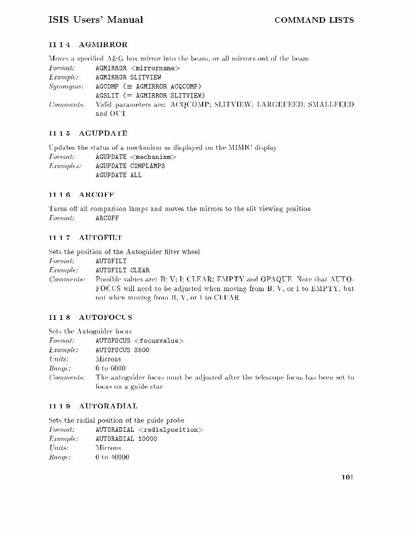
ISIS Users� Manual COMMAND LISTS
������ AGMIRROR
Moves a speci�ed A�G box mirror into the beam� or all mirrors out of the beam�Format� AGMIRROR �mirrorname�
Example� AGMIRROR SLITVIEW
Synonyms� AGCOMP �� AGMIRROR ACQCOMP
AGSLIT �� AGMIRROR SLITVIEW
Comments� Valid parameters are� ACQCOMP� SLITVIEW� LARGEFEED� SMALLFEEDand OUT�
������ AGUPDATE
Updates the status of a mechanism as displayed on the MIMIC display�Format� AGUPDATE �mechanism�Examples� AGUPDATE COMPLAMPS
AGUPDATE ALL
������ ARCOFF
Turns o� all comparison lamps and moves the mirrors to the slit viewing position�Format� ARCOFF
����� AUTOFILT
Sets the position of the Autoguider �lter wheel�Format� AUTOFILT
Example� AUTOFILT CLEAR
Comments� Possible values are� B� V� I� CLEAR� EMPTY and OPAQUE� Note that AUTO�FOCUS will need to be adjusted when moving from B� V� or I to EMPTY� butnot when moving from B� V� or I to CLEAR�
������ AUTOFOCUS
Sets the Autoguider focus�Format� AUTOFOCUS �focusvalue�
Example� AUTOFOCUS ����
Units� Microns�Range� � to �����Comments� The autoguider focus must be adjusted after the telescope focus has been set to
focus on a guide star�
������ AUTORADIAL
Sets the radial position of the guide probe�Format� AUTORADIAL �radialposition�
Example� AUTORADIAL ����
Units� Microns�Range� � to �����
���

COMMAND LISTS ISIS Users� Manual
������� AUTOTHETA
Sets the angular position of the guide probe�
Format� AUTOTHETA �thetaposition�
Example� AUTOTHETA �����
Units� Millidegrees�
Range� � to � �����
Comments� Note that values less that ���� may cause the probe to vignette the slit viewingoptics�
������� AUXFILTER
Moves the auxiliary port �lter wheel to a given position�
Format� AUXFILTER �filterposition�
Example� AUXFILTER �
Range� � to �
Comments� The �lter wheel has positions � to � and the names of the �lters mounted in eachposition are usually listed on the white board in the control room�
������� COMPFILTA
Moves the comparison lamp �lter wheel A so that the named �lter is in the beam�
Format� COMPFILTA �filtername�
Example� COMPFILTA ND���
Comments� Possible values for �ltername are� ND���� ND�� � ND�� � ND���� ND ���� GG���GG�� and CLEAR�
������� COMPFILTB
Moves the comparison lamp �lter wheel B so that the named �lter is in the beam�
Format� COMPFILTB �filtername�
Example� COMPFILTB ND���
Comments� Possible values for �ltername are� ND���� ND���� ND���� ND��� ND���� BG��OPAQUE� and CLEAR�
������� COMPLAMPS
Switches on or o� comparison lamps�
Format� COMPLAMPS �lampname�s �
Examples� COMPLAMPS CUAR�CUNE
COMPLAMPS OFF
Comments� More than one comparison lamp may be switched on� the names being joinedtogether with plus signs� Possible comparison lamps are� CUAR� CUNE� W�FEAR� FENE� NAK� and ALMGCA� Another allowed parameter is OFF� whichmay not be joined with a plus sign to any other allowed parameter�
���

ISIS Users� Manual COMMAND LISTS
������� COMPND
Sets the comparison lamp neutral density to a speci�ed value�
Format� COMPND �ndvalue�
Example� COMPND ��
Comments� Selects the combination of neutral density values in the COMPFILTA and COMP�FILTB wheels� whose sum is closest to the ndvalue� moves the �lter wheels tothose positions�
������� CUARON
Moves the mirrors to the ACQCOMP position and switches on the copper�argon lamp�
Format� CUARON
Comments� This command currently will only work if the IPCS is in use�
������ CUNEON
Moves the mirrors to the ACQCOMP position and switches on the copper�neon lamp�
Format� CUNEON
Comments� This command currently will only work if the IPCS is in use�
������� MAINFILTC
Moves the main colour �lter slide to a given position�Format� MAINFILTC �filterposition�
Examples� MAINFILTC �
MAINFILTC GG���
Comments� The position can be speci�ed as a �lter position number in the range ���� as thename of a �lter which has been identi�ed by its barcode� or as OUT to removethe �lters from the beam�
������� MAINFILTND
Moves the main neutral density �lter slide to a given position�
Format� MAINFILTND �filterposition�
Examples� MAINFILTND �
MAINFILTND ND���
Comments� The position can be speci�ed as a �lter position number in the range ���� as thename of a �lter which has been identi�ed by its barcode� or as OUT to removethe �lters from the beam�
������� TV DIRECT ��
Selects the direct viewing position at a scale of �� arcsec�mm�
Format� TV DIRECT �
Comments� Procedure which moves the mirrors to the ACQCOMP position� selects a scaleof �� arcsec�mm and the correct value of TVFOCUS�
���

COMMAND LISTS ISIS Users� Manual
������� TV DIRECT �
Selects the slit viewing position at a scale of arcsec�mm�
Format� TV DIRECT �
Comments� Procedure which moves the mirrors to the ACQCOMP position� selects a scaleof arcsec�mm and the correct value of TVFOCUS�
������� TV SLIT ��
Selects the slit viewing position at a scale of �� arcsec�mm�
Format� TV SCALE �
Comments� Procedure which moves the mirrors to the SLITVIEW position� selects a scale of�� arcsec�mm and the correct value of TVFOCUS�
������� TV SLIT �
Selects the slit viewing position at a scale of arcsec�mm�
Format� TV SCALE �
Comments� Procedure which moves the mirrors to the SLITVIEW position� selects a scale of arcsec�mm and the correct value of TVFOCUS�
������� TVFILT
Moves the �lter wheel in front of the TV camera to a named �lter�
Format� TVFILT �filtername�
Example� TVFILT R
Comments� Possible values are� B� V� R� CLEAR and EMPTY� The TV focus must beadjusted when changing from EMPTY to one of the other positions� Notethat there may be an opaque mask in position EMPTY� if so posi�tion CLEAR should be used instead�
������� TVFOCUS
Sets the TV focus�
Format� TVFOCUS �focusvalue�
Example� TVFOCUS ����
Units� Microns�
Range� � to �����
Comments� To adjust the TV focus so that the TV is focussed on the slit� or so that a staris in focus on the TV in direct mode�
������� TVSCALE
Sets the TV scale�
Format� TVSCALE �tvscalevalue�
Example� TVSCALE �
���

ISIS Users� Manual COMMAND LISTS
Comments� Puts the correct focal reduction optics �or no optics at all� in front of the TVcamera for a speci�ed scale �in arcsec�mm�� either in slit viewing or direct mode�Allowed values of the TV scale are and ���
��� Autoguider Commands
������ ACQINT
Changes the Autoguider integration time when acquiring�Format� ACQINT �integrationtime�Example� ACQINT ���
Units� Milliseconds�Comments� Equivalent to �integrationtime� AIT at the Autoguider terminal�
������ FIELD
Causes the CCD autoguider to read out its whole �eld of view and look for a suitable guide star�Format� FIELD
Comments� Does not return control to the user until this process is complete� Equivalent to FIELD at the autoguider interface�
������ FOLLOW
Causes the CCD Autoguider to follow a star image and to send error signals to the TelescopeControl Computer� or to stop doing so�Format� FOLLOW �onoroff� �n�
Examples� FOLLOW ON
Synonyms� FON �� FOLLOW ON
FOFF �� FOLLOW OFF
Comments� Valid values of the �rst parameter are ON and OFF� the second is the number ofAutoguider integrations per guiding error is normally �� Equivalent to n GUI
and GUI�OFF at the Autoguider terminal� FOLLOW does not start the telescopeautoguiding� it is necessary to issue the PROBE and AUTOGUIDER commands to theTCS� either through the ICL interface or at the TCS terminal� to do this� Fordetails of these commands refer to THE WHT USERS� MANUAL�
������ GUIINT
Changes the Autoguider integration time when guiding�Format� GUIINT �integrationtime�Example� GUIINT ���
Units� Milliseconds�Comments� Equivalent to �integrationtime� GIT at the Autoguider terminal�
���� ISIS Commands
������ ANAMORPHOTIC
Moves the Anamorphotic lens in or out�
���

COMMAND LISTS ISIS Users� Manual
Format� ANAMORPHOTIC �direction�
Example� ANAMORPHOTIC IN
Comments� Valid parameters are IN or OUT� NOTE THAT THE ANAMORPHOTICLENS HAS NOT YET BEEN ACQUIRED� AND THIS MECHA�NISM HAS BEEN DISABLED UNTIL IT HAS�
������ BCOLL
Controls the Blue collimator�Format� BCOLL �position�
Example� BCOLL ���
Units� Microns�Range� � to �����
Comments� Moves� stops or initialises the Blue collimator� Valid parameters are a positionin microns� STOP and INIT�
������ BLUEGRAT
Controls the Blue grating�Format� BLUEGRAT �angle�
Example� BLUEGRAT ���
Synonym� BGRAT
Units� Millidegrees�Range� � to �������Comments� Moves� stops or initialises the Blue Grating� or reprograms the SMDM which
controls it� Valid parameters are an angle in millidegrees� STOP� INIT andREPROGRAM� The last option should only be used in exceptional circumstances�
������ BLUEXDISP
Controls the blue cross�disperser�
Format� BLUEXDISP �position�
Example� BLUEXDISP IN
Comments� Moves� stops or initialises the Blue cross�disperser� or reprograms the SMDMwhich controls it� Valid parameters are� IN� OUT� STOP� INIT� and REPRO�GRAM� The last option should only be used in exceptional circumstances� THISITEM HAS NOT YET BEEN DELIVERED AND THIS COMMAND
WILL NOT BE IMPLEMENTED UNTIL IT HAS�
������ BFILTA
To move �lter slide A in the Blue beam to a given position�Format� BFILTA �position�
Example� BFILTA �
Range� � to �� or a named position�
Comments� Moves� stops or initialises Blue Filter A� Valid parameters are a position in therange � to �� a named �lter �listed on the ISIS MIMIC page�� OUT� STOP�
���

ISIS Users� Manual COMMAND LISTS
INIT and REPROGRAM� The last option should only be used in exceptionalcircumstances�
������ BFILTB
To move �lter slide B in the Blue beam to a given position�
Format� BFILTB �position�
Example� BFILTB �
Range� � to �� or a named position�
Comments� Moves� stops or initialises Blue Filter B� Valid parameters are a position in therange � to �� a named �lter �listed on the ISIS MIMIC page�� OUT� STOP�INIT and REPROGRAM� The last option should only be used in exceptionalcircumstances�
����� BFOLD
Controls the slide containing the folding �at for the blue camera and the dichroic mirror�
Format� BFOLD �position�
Example� BFOLD DICHROIC
Synonym� BLUE FOLD
Comments� Moves� stops or initialises the slide containing the folding �at for the blue cameraand the dichroic mirror� Valid parameters are a number in the range � to �� MIR�ROR �� ��� DICHROIC �� ��� CLEAR �� ��� STOP� INIT and REPROGRAM�The last option should only be used in exceptional circumstances�
������ BHART
Controls the position of the Blue beam Hartmann shutters�
Format� BHART �position�
Examples� BHART
BHART BOTH IN
Range� � to �� with named equivalents�
Comments� Valid parameters are a number in the range � to �� BOTH IN �� ��� LEFT IN�� ��� RIGHT IN �� �� and BOTH OUT �� ���
������ CENWAVE
Sets a grating to give a speci�ed central wavelength on the detector�
Format� CENWAVE �gratingname� �wavelength�
Example� CENWAVE RED ����
Synonym� ISIS CENWAVE
Units� wavelength is speci�ed in �Angstroms�
Comments� A procedure to work out the grating angle required to give a given central wave�length on the detector� and then to set the grating angle to that wavelength�The grating name� which must be RED or BLUE� and the required central wave�length in �Angstroms are speci�ed on the command line� The grove spacing on
��

COMMAND LISTS ISIS Users� Manual
the grating must be correct in the database� this can be checked on the mimicscreen�
������� CHANGE
An interactive procedure to allow the user to change gratings or �lters and to update thedatabase�Format� CHANGE
Comments� The change procedure allows the user to change gratings or �lters� It prompts theuser for the item that requires changing� then moves that mechanism to its changeposition� moves the dekker to the change position if a �lter is to be changed� andunlocks the relevant door� After the change has been made it locks the door andupdates the database�
������� DEKKER
Moves the Dekker slide�
Format� DEKKER �position�
Examples� DEKKER �
DEKKER BARRED
Range� � to � or named dekkers�Comments� Moves� stops or initialises the dekker slide� or reprograms the SMDM which con�
trols the dekker slide� Valid parameters are a dekker position in the range � to � a named dekker as listed on the MIMIC display� OUT� STOP� INIT and RE�PROGRAM� The last option should only be used in exceptional circumstances�
������� FCP
Moves the slide which contains the Field Lens� Calcite block and Polaroid Filter�Format� FCP �position�
Example� FCP CALCITE
Synonyms� FIELD LENS �� FCP FIELD LENS
FIELDLENS �� FCP FIELD LENS
POLAROID �� FCP POLAROID
CALCITE �� FCP POLAROID
FCP CLEAR �� FCP CLEAR
FCPCLEAR �� FCP CLEAR
Range� � to �� or named positions�
Comments� Moves� stops� or initialises the Field Lens� Calcite and Polaroid slide or reprogramsthe SMDM which controls it� Valid parameters are a position in the range � to�� FIELD LENS �� ��� CALCITE�� ��� POLAROID �� ��� OUT �� ��� STOP�INIT and REPROGRAM� The last option should only be used in exceptionalcircumstances�
������� GRATING DOOR
Locks or unlocks the grating access doors�
���

ISIS Users� Manual COMMAND LISTS
Format� GRATING DOOR �position�
Example� GRATING DOOR OPEN
Comments� This is an interactive procedure to unlock and lock both grating doors� Validparameters are OPEN and CLOSE� LOCK and UNLOCK� GRATING DOOR OPEN
or GRATING DOOR UNLOCK will unlock the doors and invite you to open themmanually� GRATING DOOR CLOSE or GRATING DOOR LOCK will invite you to checkthat they are closed� and lock them when you have veri�ed this�
������� HW POLAR
Controls the Half Wave Plate�Format� HW POLAR �function� �parameter�
Examples� HW POLAR MOVE IN
HW POLAR ROTATE ��
HW POLAR ANGLE ���
HW POLAR STOP ROTATE
Synonyms� HWIN � HW POLAR MOVE IN
HWOUT � HW POLAR MOVE OUT
HWP � HW POLAR ANGLE
HWPROT � HW POLAR ROTATE
Units� Angles are speci�ed in units of a tenth of a degree�Rotation rates are speci�ed in units of a tenth of a Hz�
Range� Angle in range � to �����Rotation rate in range �� to �� �
Comments� function can have the values ROTATE� ANGLE� MOVE or STOP�The parameter for HW POLAR ROTATE is a rotation rate in units of a tenth of a Hz�this sets the plate in continuous rotation�The parameter for HW POLAR ANGLE is an angle in units of a tenth of a degree�this sets the plate to a �xed angle�The parameter for HW POLAR MOVE can be IN or OUT� this moves the plate in orout�The parameter for HW POLAR STOP can be ROTATE or MOVE� this stops theplate rotating or moving�Notes�� The wave plate must be in before continuous rotation is started� and theif the wave plate is rotating it must be stopped before sending it to a �xed angle�
������� ISIS CONFIG
Con�gures the folding mirror slides for observing with a named combination of arms�Format� ISIS CONFIG �configuration�
Example� ISIS CONFIG BLUEANDRED
Comments� Valid parameters are RED� BLUE� FOS� BLUEANDRED and BLUEANDFOS�
������� ISIS INIT
Initialises a named mechanismFormat� ISIS INIT �mechanism�
���

COMMAND LISTS ISIS Users� Manual
Example� ISIS INIT RED GRATING
Comments� Mechanisms which can be initialised include��RED GRATING� BLUE GRATING� RED COLLIMATOR�BLUE COLLIMATOR� RED FILTER A� RED FILTER B�BLUE FILTER A� BLUE FILTER B� DEKKER�SLIT UNIT� HW POLAR� QW POLAR� RED FOLD�BLUE FOLD and FLENS CALC POLAR�
������ ISIS MOVE
Moves a speci�ed mechanismFormat� ISIS MOVE �mechanism� �position�
Example� ISIS MOVE RED GRATING ����
Comments� The list of mechanisms which can be moved includes those which can be initialisedwith ISIS INIT� plus ANAMORPHOTIC� LID COVER and SLIT JAWS�
������� ISIS UPDATE
Updates the status of a mechanism on the MIMIC display�Format� ISIS UPDATE �mechanism�
Example� ISIS UPDATE SLIT
Comments� The list of mechanisms which can be updated is the same as that which can bemoved with ISIS MOVE�
������� LID
Opens or closes the Lid Cover�Format� LID �direction�
Example� LID OPEN
Comments� Valid parameters are OPEN and CLOSE�
������� QW POLAR
Controls the Quarter Wave Plate�Format� QW POLAR �function� �parameter�
Examples� QW POLAR MOVE IN
QW POLAR ROTATE ��
QW POLAR ANGLE ���
QW POLAR STOP ROTATE
Synonyms� QWIN � QW POLAR MOVE IN
QWOUT � QW POLAR MOVE OUT
QWP � QW POLAR ANGLE
QWPROT � QW POLAR ROTATE
Units� Angles are speci�ed in units of a tenth of a degree�Rotation rates are speci�ed in units of a tenth of a Hz�
Range� Angle in range � to �����Rotation rate in range �� to �� �
���
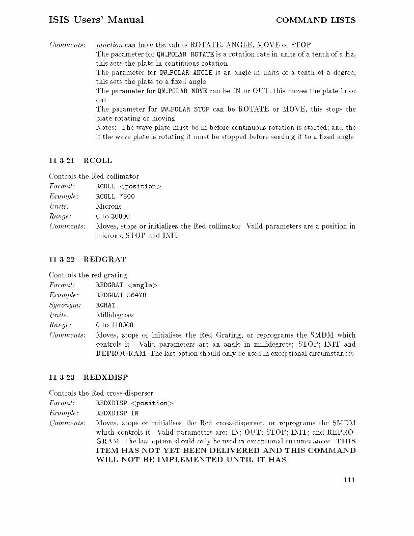
ISIS Users� Manual COMMAND LISTS
Comments� function can have the values ROTATE� ANGLE� MOVE or STOP�The parameter for QW POLAR ROTATE is a rotation rate in units of a tenth of a Hz�this sets the plate in continuous rotation�The parameter for QW POLAR ANGLE is an angle in units of a tenth of a degree�this sets the plate to a �xed angle�The parameter for QW POLAR MOVE can be IN or OUT� this moves the plate in orout�The parameter for QW POLAR STOP can be ROTATE or MOVE� this stops theplate rotating or moving�Notes�� The wave plate must be in before continuous rotation is started� and theif the wave plate is rotating it must be stopped before sending it to a �xed angle�
������� RCOLL
Controls the Red collimator�
Format� RCOLL �position�
Example� RCOLL ����
Units� Microns�
Range� � to ������
Comments� Moves� stops or initialises the Red collimator� Valid parameters are a position inmicrons� STOP and INIT�
������� REDGRAT
Controls the red grating�
Format� REDGRAT �angle�
Example� REDGRAT ����
Synonym� RGRAT
Units� Millidegrees�
Range� � to �������
Comments� Moves� stops or initialises the Red Grating� or reprograms the SMDM whichcontrols it� Valid parameters are an angle in millidegrees� STOP� INIT andREPROGRAM� The last option should only be used in exceptional circumstances�
������� REDXDISP
Controls the Red cross�disperser�
Format� REDXDISP �position�
Example� REDXDISP IN
Comments� Moves� stops or initialises the Red cross�disperser� or reprograms the SMDMwhich controls it� Valid parameters are� IN� OUT� STOP� INIT� and REPRO�GRAM� The last option should only be used in exceptional circumstances� THISITEM HAS NOT YET BEEN DELIVERED AND THIS COMMANDWILL NOT BE IMPLEMENTED UNTIL IT HAS�
���

COMMAND LISTS ISIS Users� Manual
������� RFILTA
To move �lter slide A in the Red beam to a given position�Format� RFILTA �position�Example� RFILTA �
Range� � to �� or a named position�Comments� Moves� stops or initialises Red Filter A� Valid parameters are a position in the
range � to �� a named �lter �listed on the ISIS MIMIC page�� OUT� STOP�INIT and REPROGRAM� The last option should only be used in exceptionalcircumstances�
������� RFILTB
To move �lter slide B in the Red beam to a given position�Format� RFILTB �position�
Example� RFILTB �
Range� � to �� or a named position�Comments� Moves� stops or initialises Red Filter B� Valid parameters are a position in the
range � to �� a named �lter �listed on the ISIS MIMIC page�� OUT� STOP�INIT and REPROGRAM� The last option should only be used in exceptionalcircumstances�
������� RFOLD
Controls the slide containing the folding �at for the red camera�Format� RFOLD �position�Example� RFOLD MIRROR
Synonym� RED FOLD
Comments� Moves� stops or initialises the slide containing the folding �at for the red camera�Valid parameters are a number in the range � to �� MIRROR �� ��� CLEAR�� ��� STOP� INIT and REPROGRAM� The last option should only be used inexceptional circumstances�
������ RHART
Controls the position of the Red beam Hartmann shutters�Format� RHART �position�
Examples� RHART
RHART BOTH IN
Range� � to �� with named equivalents�Comments� Valid parameters are a number in the range � to �� BOTH IN �� ��� LEFT IN
�� ��� RIGHT IN �� �� and BOTH OUT �� ���
������� SLIT
Sets the Slit jaws to a speci�ed width�Format� SLIT �slitwidth�
Example� SLIT ���
���

ISIS Users� Manual COMMAND LISTS
Synonym� SLITARC �also allows STOP as a parameter��Units� Microns�Range� � to ����
������� SLIT DOOR
Locks or unlocks the slit area access door�Format� SLIT DOOR �position�
Example� SLIT DOOR OPEN
Comments� This is an interactive procedure to unlock and lock the slit access door� Validparameters are OPEN and CLOSE� LOCK and UNLOCK SLIT DOOR OPEN orSLIT DOOR UNLOCK will unlock the door and invite you to open it manually�SLIT DOOR CLOSE or SLIT DOOR LOCK will invite you to check that it is closed�and lock it when you have veri�ed this�
������� SLIT UNIT
Selects whether the long slit unit or the multi�slit and �bre slit unit is in the beam�Format� SLIT UNIT �position�
Example� SLIT UNIT LONG SLIT
Synonyms� LSLIT �� SLIT UNIT LONG SLIT
MSLIT �� SLIT UNIT MSLIT FIBRES
Comments� Moves� stops or initialises the slit unit� or reprograms the SMDM which controlsit� Valid parameters are a position in the range � to �� LONG SLIT �� ���MSLIT FIBRES �� �� STOP� INIT and REPROGRAM� The last option shouldonly be used in exceptional circumstances�
���� FOS Commands
������ FIFOCUS
Returns the status of the FOS Focus and updates the MIMIC�Format� FIFOCUS
Synonym� FIF
Comments� AT PRESENT THE FOS MIMIC DOES NOT WORK�
������ FIGLOBAL
Returns status of all FOS mechanisms�Format� FIGLOBAL
Synonym� FIG
Comments� AT PRESENT THE FOS MIMIC DOES NOT WORK�
������ FIHARTMANN
Returns status of the FOS Hartmann shutters�Format� FIHARTMANN
Synonym� FIHA
���

COMMAND LISTS ISIS Users� Manual
Comments� AT PRESENT THE FOS MIMIC DOES NOT WORK�
������ FIHTILT
Returns status of the FOS Platform Horizontal Tilt�
Format� FIHTILT
Synonym� FIHT
Comments� AT PRESENT THE FOS MIMIC DOES NOT WORK�
������ FIVTILT
Returns status of the FOS Platform Vertical Tilt�
Format� FIVTILT
Synonym� FIVT
Comments� AT PRESENT THE FOS MIMIC DOES NOT WORK�
������ FMFOCUS
Controls the FOS Focus�
Format� FMFOCUS �focusvalue�
Example� FMFOCUS ���
Synonym� FMF
Units� The units are units of microns�
Range� � to ��
����� FMHARTMANN
Controls the FOS Hartmann shutters�
Format� FMHARTMANN �position�
Example� FMHARTMANN LEFT
Synonym� FMHA
Comments� Valid parameters are� LEFT �left shutter in beam�� RIGHT �right shutter inbeam� and CLEAR �both shutters out of beam��
������ FMHTILT
Controls the FOS Platform Horizontal Tilt�
Format� FMHTILT �value�
Example� FMHTILT ��
Synonym� FMHT
Units� Each unit subtends a displacement of microns across the diameter of the plat�form�
Range� � to ��
���

ISIS Users� Manual COMMAND LISTS
������ FMMONITOR
Turns FOS monitor mode on or o��Format� FMMONITOR �onoroff�
Example� FMMONITOR ON
Synonym� FMM
Comments� Valid parameters are ON and OFF�
������� FMRESET
Software reset of the FOS ms�Format� FMRESET
Synonym� FMR
������� FMVTILT
Controls the FOS Platform vertical Tilt�Format� FMVTILT �value�Example� FMVTILT ��
Synonym� FMVT
Units� Each unit subtends a displacement of microns across the diameter of the plat�form�
Range� � to ��
������� FSGLOBAL
Stops all FOS mechanisms�Format� FSGLOBAL
Synonym� FSG
��� Data Taking Commands CCD Detectors
CCD data are taken and stored with the Data Acquisition System� which provides a large rangeof commands for taking data of various types� and storing the data with or without the headerinformation in various forms on the Vax discs� A description of the system� together with acomplete list of the commands� is given in William Herschel Telescope Instrument control anddata acquisition system user manual�� by S�W� Unger � G�T� Rixon� and only a subset of thecommands� relevant to observing with CCDs on ISIS� are listed here� Many commands do almostidentical things� for instance the commands RUN� FLAT� ARC� and SKY di�er only in one headeritem in the data �le� The commands SCRATCH and PROMOTE are intended for use by automaticsetup procedures yet to be written�
������ ABORT
Terminate an exposure early� abandoning the data�Format� ABORT �channel�
Channel� The name of the CCD data acquisition channel to be used�Examples � ABORT RED
���

COMMAND LISTS ISIS Users� Manual
Comments� This command terminates the current CCD exposure� throwing away the data�
������ ARC
This is equivalent to the RUN command� but intended for exposures of arc lamps rather thanobservations of astronomical targets�
Format� ARC �channel� �time� ���string���
Channel� The name of the CCD data acquisition channel to be used�
Time� The exposure time in seconds
Title� A title for the observation �optional�
Examples � ARC RED �� �CuAr arc ���� Angstrom�
Comments� As for the RUN command� except that the observation type is set in the headersas being an arc exposure�
������ BIAS
Takes a single bias frame �a zero second exposure�� and transfers the data plus headers to anHDS �le on the system computer�
Format� BIAS �channel� ���string���
Channel� The name of the CCD data acquisition channel to be used�
Title� A title for the observation �optional�
Examples � BIAS RED �Bias frame ��
Comments� As for the RUN command� except that exposure time will be zero� and the ob�servation type is set in the headers as being a BIAS exposure�
������ BIN
Bins a CCD detector
Format� BIN �channel� �xbin� �ybin�
Channel� The name of the CCD data acquisition channel to be binned�
Xbin� The binning factor in X� This must be an integer in the range � � ���
Ybin� The binning factor in Y� This must be an integer in the range � � ���
Examples � BIN RED � �
Comments� This command sets the binning factors on the named channel in both X and Y�and enables windowing and binning on the CCD�
������ CCDINIT
Initialises a CCD�
Format� CCDINIT �detectorname�
Example� CCDINIT RED
Comments� Initialises a CCD and updates the MIMIC display with data from the CCD con�troller� This is performed in the startup sequence� and this command is onlyrequired if the startup sequence fails�
���

ISIS Users� Manual COMMAND LISTS
������ CONTINUE
Continue a paused CCD exposure�
Format� CONTINUE �channel�
Channel� The name of the CCD data acquisition channel to be used�
Examples � CONTINUE RED
Comments� This command resumes a paused CCD exposure� opening the CCD shutter� Theshutter will not be opened if it was closed when the exposure was paused �as inthe case of a dark exposure�� The command will be aborted if no exposure is inprogress�
����� DARK
Takes an exposure without opening the CCD shutter� and transfers the data plus headers to anHDS �le on the system computer�
Format� DARK �channel� �time� ���string���
Channel� The name of the CCD data acquisition channel to be used�
Time� The exposure time in seconds
Title� A title for the observation �optional�
Examples � DARK RED ���� �Measuring dark counts�
Comments� As for the RUN command� except that the CCD shutter is not opened� and theobservation type is set in the headers as being a DARK exposure�
������ DIR
Lists the run and scratch �les taken during the night�
Format� DIR
Comments� Lists the �les in the directories to which run and scratch �les are currently beingwritten� Normal DCL quali�ers �e�g� �SIZE� are accepted�
������ DISABLE WINDOWS
Disables windows and binning factors previously set up on a CCD detector
Format� DISABLE WINDOWS �channel�
Channel� The name of the CCD data acquisition channel�
Examples � DISABLE WINDOWS FOS
Comments� This command disables windowing and binning of the CCD� The command doesnot delete the systems memory of window parameters and binning factors� it onlystops the system applying it� The windows and binning can be reenabled withthe command ENABLE WINDOWS�
������� DISKSPACE
Reports the available diskspace on the data disk and on the home disk of the OBSERVER�
Format� DISKSPACE
��

COMMAND LISTS ISIS Users� Manual
������� ENABLE WINDOWS
Enables windows and binning factors previously disabled on a CCD detector
Format� ENABLE WINDOWS �channel�
Channel� The name of the CCD data acquisition channel �
Examples � ENABLE WINDOWS FOS
Comments� Where windowing and binning of the CCD have been disabled using the DIS�ABLE WINDOWS command� this command reenables them�
������� FINISH
Terminate an exposure early� saving data and headers to disk�
Format� FINISH �channel�
Channel� The name of the CCD data acquisition channel to be used�
Examples � FINISH RED
Comments� This command terminates the current CCD exposure� saving the data to disk asif the exposure had completed normally�
������� FLAT
This is equivalent to the RUN command� but intended for exposures of �at �elds rather thanastronomical targets
Format� FLAT �channel� �time� ���string���
Channel� The name of the CCD data acquisition channel to be used�
Time� The exposure time in seconds
Title� A title for the observation �optional�
Examples � FLAT BLUE �� �Tungsten flat ���� Angstrom�
Comments� As for the RUN command� except that the observation type is set in the headersas being a �at�eld exposure�
������� GLANCE
Takes an exposure and transfers the data into the Detector Memory System for inspection� butnot to the system computer�
Format� GLANCE �channel� �obstype� �time�
Channel� The name of the CCD data acquisition channel to be used�
Time� The exposure time in seconds
Obstype� The observation type� Valid observation types are ARC� BIAS� DARK� FLAT�and TARGET�
Examples � GLANCE RED ARC �
Comments� This command is intended for a quick�look at the data� to verify for example thatthe intensity level is as expected before carrying out a proper exposure� The datawill be lost when the next exposure is carried out on the same data acquisitionchannel� To save the data� use the KEEP command�
���

ISIS Users� Manual COMMAND LISTS
������� KEEP
Copies a previously completed glance exposure to disk on the system computer� collecting head�ers and assigning a run number in the process�Format� KEEP �channel� ���title���
Channel� The name of the CCD data acquisition channel to be used�Title� A title for the observation �optional�
helpitemExamples � KEEP RED
Comments� The system will report the allocated run number�
������� KILLMULT
Stops a sequence of multiple exposures�Format� KILLMULT �channel�
Channel� The name of the CCD data acquisition channel�Example� KILLMULT RED
Comments� The current exposure in the series is left to complete normally� and all pendingexposures are cancelled� The channel becomes ready for another command whenthe current exposure completes� KILLMULT can be followed by FINISH or ABORTfor a complete stop�
������ MULTRUN
Takes a sequence of exposures� all of the same exposure timeFormat� MULTRUN �channel� �nruns� �time� ���title���
Channel� The name of the CCD data acquisition channel to be used�Time� The exposure time in secondsExample� MULTRUN RED �� �� �AX DRACO �� exposures�
Comments� There also commands MULTARC� MULTFLAT� MULTBIAS� MULTDARK which have sim�ilar formats� except that MULTBIAS does not require a time�
������� NEWTIME
Change the exposure time of an exposure in progress�Format� NEWTIME �channel� �time�
Example� NEWTIME RED ���
Channel� The name of the CCD data acquisition channel to be used�Time� The exposure time in secondsComments� The system will not accept an exposure time less than the current exposed time�
������� PAUSE
Pauses a CCD exposure�Format� PAUSE �channel�
Channel� The name of the CCD data acquisition channel to be used�Examples � PAUSE RED
Comments� This command suspends the current CCD exposure� closing the CCD shutter�The command will be aborted if no exposure is in progress�
���

COMMAND LISTS ISIS Users� Manual
������� PROMOTE
Promotes a scratch data�le to the main data area on the system computer� assigning it a runnumber in the process�
Format� PROMOTE �filenum�
Filenum� The number of the scratch �le
Examples � PROMOTE �
Comments� The system will report the allocated run number� However� since the headers forthe observation are collected when the data is originally taken� the run numberwill not appear in the headers�
������� RAT WAIT
RAT WAITs for an exposure to complete before returning control to ICL�
Format� RAT WAIT �channel� �timeout�
Channel� The name of the CCD data acquisition channel to be used�
Timeout� The maximum time to wait �seconds�
Examples � RAT WAIT RED ��
Comments� The commands for carrying out CCD exposures normally return control to ICLbefore they complete� Whilst this is desirable in normal operation� it makes itimpossible to write ICL procedures to carry out a number of exposures sequen�tially �as in a focus run for example�� Such ICL procedures can be producedusing the WAIT command �see section � for examples�� The timeout parameterof the WAIT command forces it to return an error to ICL if the exposure doesnot complete� it is recommended that timeouts be made generous�
������� RUN
Takes an exposure of an astronomical target� and transfers the data plus headers to an HDS �leon the system computer�
Format� RUN �channel� �time� ���string���
Channel� The name of the CCD data acquisition channel to be used�
Time� The exposure time in seconds
Title� A title for the observation �optional�
Examples � RUN RED �� �NGC��� nucleus�
Synonym� TARGET
Comments� This command takes a single exposure of an astronomical target� collects headerinformation pertaining to that exposure� and transfers both data and headersinto an HDS �le on the system computer� During the observation the systemwill report the run number allocated� and will announce the start and end of theexposure� The user will be informed once the data has been written to disk� untilthis noti�cation has been received� no further exposure can be carried out on thisdetector channel� Exposures cannot be carried out until the detector has beenset up using the SETUP command�
���

ISIS Users� Manual COMMAND LISTS
������� SCRATCH
Takes an exposure� and transfers the data plus headers to a numbered HDS �le in the scratcharea on the system computer�
Format� SCRATCH �channel� �filenum� �obstype� �time� ���string���
Channel� The name of the CCD data acquisition channel to be used�Filenum� The number of the scratch �le
Obstype� The observation type� Valid observation types are ARC� BIAS� DARK� FLAT�and TARGET�
Time� The exposure time in seconds
Title� A title for the observation �optional�Examples � SCRATCH RED � ARC ��
Comments� As for the RUN command� except that the data is �nally transferred not to themain data area on the system computer but to a scratch area� This command isintended primarily for use with setup procedures�
������� SETUP
Sets up the default detector format� and prepares a channel for taking data�Format� SETUP �channel�
Channel� The name of the CCD data acquisition channel to be used�Examples � SETUP RED
Comments� The system will read the default detector format from the con�guration databaseand set the detector up accordingly� The user will be informed when the set�upis complete� No exposures can be made until the channel has been set up by thiscommand�
������� SKY
This is equivalent to the RUN command� but intended for sky exposures rather than observationsof astronomical targets�Format� SKY �channel� �time� ���string���
Channel� The name of the CCD data acquisition channel to be used�Time� The exposure time in secondsTitle� A title for the observation �optional�
Examples � SKY TAURUS �� TITLE��Twilight flatfield� B filter�
Comments� As for the RUN command� except that the observation type is set in the headersas being a sky �at �eld�
������� SLOUCH
Sets the CCD readout speed to STANDARD SPEED�
Format� SLOUCH �channel�
Channel� The name of the CCD data acquisition channel�Example� SLOUCH RED
Synonym� READOUT SPEED SLOUCH
Comments� This sets the CCD to its standard readout mode� used for normal observing�
���

COMMAND LISTS ISIS Users� Manual
������ SPEEDY
Sets the CCD readout speed to QUICK SPEED�Format� SPEEDY �channel�
Channel� The name of the CCD data acquisition channel�Example� SPEEDY RED
Synonym� READOUT SPEED SPEEDY
Comments� This sets the CCD to its fast readout mode� usually only used for setting up� Thepenalty of the fast readout is a slightly higher readout noise� The bias and gainof the CCD will also change�
������� WINDOW
Windows a CCD detectorFormat� WINDOW �channel�
Channel� The name of the CCD data acquisition channel to be windowed�Examples � WINDOW BLUE
Comments� The system will prompt the user for the number of windows to be set�up� andthe origin and size of each window� Windowing and binning of the CCD willbe enabled� At present use of more than one window on a CCD is not
recommended�
������� WINK
Takes a scratch exposure as for the SCRATCH command� except that no headers are collected�Format� WINK �channel� �filenum� �obstype� �time� �TITLE��string��
Channel� The name of the CCD data acquisition channel to be used�Filenum� The number of the scratch �leObstype� The observation type� Valid observation types are ARC� BIAS� DARK� FLAT�
and TARGET�Time� The exposure time in secondsTitle� A title for the observation �optional�Examples � WINK RED � ARC ��
Comments� As for the SCRATCH command� except that no headers are collected�
���� Data Taking Commands IPCS detector
������ EXPOSE
Starts an exposure on a speci�ed detector�Format� EXPOSE �detectorname� �exposuretime�
Example� EXPOSE IPCS ���
Synonym� EI �� EXPOSE IPCS
Units� Seconds�Comments� If the previous exposure has not been kept EXPOSE will prompt the user to
do this� but EXPOSE will store the data only in the DMS� not in a disc �le�EXPOSE IPCS does not open the shutter at the start of the exposure� nor closeit at the end� this must be done explicitly�
���

ISIS Users� Manual COMMAND LISTS
������ EXPOSENP
Starts an exposure on a speci�ed detector without collecting the archive packets�
Format� EXPOSENP �detectorname� �exposuretime�
Example� EXPOSENP IPCS ���
Synonym� ENPI �� EXPOSE IPCS
Units� Seconds�
Comments� This command works as expose� but does not collect archive packets� This savestime if you do no expect to KEEP the data� However if you run KEEP afterEXPOSENP then KEEP will collect the archive packets�
������ IPCONT
Continues a paused IPCS exposure�
Format� IPCONT
Comments� To continue an exposure paused by IPPAUSE
������ IPCSCLOSE
Closes the IPCS shutter�
Format� IPCSCLOSE
Synonym� IPC
������ IPCSFORMAT
Sets up the data window and resolution parameters for taking IPCS data�
Format� IPCSFORMAT
Comments� This is an interactive procedure which prompts for the parameters required toset up the IPCS and the DMS for a given data format� Brie�y these are��
� Number of CCD rows �the spatial direction� read out �NROWS�� This must bein the range � to ���
� Start row on CCD� This must be chosen so that the entire region read out ison the chip�
� Number of CCD rows read into bu�er� This should not exceed �NROWS � ���and may not exceed ��
� Spatial resolution factor along the slit� This can be � �coarsest resolution�� ��� or �
� Number of CCD pixels read into the bu�er in the spectral direction� This maynot exceed ����
� Resolution factor in the spectral direction� This can be �� �� or � and isnormally �
The procedure sets the start of the CCD window in the spectral direction to pixel��� to avoid the unthinned region of the CCD� For details of how to adjust this� and for detailsof how to set up more complicated windows� refer to Chapter of the IPCS�II Users Manual�
���

COMMAND LISTS ISIS Users� Manual
������ IPCSOPEN
Opens the IPCS shutter�
Format� IPCSOPEN
Synonym� IPO
Comments� Please watch the raw video display when the shutter is opened�
����� IPCSSDC
To set the IPCS format up in a way suitable for calculating the S�distortion correction�Format� IPCSSDC
Comments� Sets up an IPCS window at full resolution in both directions� centred in Y on thepart on the chip on which the image of the narrow dekker will fall�
������ IPNEWT
Changes the exposure time for an IPCS exposure�Format� IPNEWT �newexposuretime�
Example� IPNEWT ���
Units� Seconds�Comments� The new time should be greater than the exposed time so far�
������ IPPAUSE
Pauses an IPCS exposure�Format� IPPAUSE
Comments� Pauses data collection during an IPCS exposure� but does not close the shutter�
������� IPSTOP
Stops an IPCS exposure�Format� IPSTOP
Comments� The data in the DMS bu�er may then be transferred to the Vax disc with KEEP�otherwise the disc �le must be closed with CLOSE� Does not close the IPCS shutter�
������� IPUPDATE
Updates the IPCS exposed time on the MIMIC display�Format� IPUPDATE
Comments� Causes the IPCS exposes time to update on the MIMIC display� if for some reasonit is not doing so�
������� KEEP
Transfers a data frame from the DMS bu�er to the Vax ��� Data disc�Format� KEEP �detectorname�
Example� KEEP IPCS
Synonym� KI �� KEEP IPCS
���

ISIS Users� Manual COMMAND LISTS
Comments� Transfers the data to a disc �le in the directory DCT OBSDIR� on the Vax���� The disc �le will be given a name which consists of a �le number� which issequential� and the name of the DMS bu�er that the data came from�
������� CLEAR OVERILLUM
Clears the Overillumination status�Format� CLEAR OVERILLUM
Comments� An overillumination trip closes the shutter and will not allow the user to open ituntil the overillumination status has been cleared� It is important for the user toestablish why the overillumination condition occurred� and to ensure that it willnot happen again� before issuing this command�
������� OVERSCAN
Sets the area of the CCD read out to be the whole area of the chip�Format� OVERSCAN
Comments� This ensures the whole of the CCD is read out� but unlike the overscan switch onthe INT IPCS it does not scan the whole of the output of the EMI image tube�there is no way of doing this� Beware of possible bright light sources o� the edgeof the chip� After using this command it will be necessary to set up the observingwindow again with IPCSFORMAT�
������� STANDBY
Runs the IPCS EHT down slowly�Format� STANDBY
Comments� This is equivalent to setting the rotary switch on the IPCS cubicle on the telescopeto STANDBY� and pressing the LOAD� button� In either case it is importantto verify that the IPCS EHT has in fact run down� by checking the EHT supplyon the telescope or the raw video display� before switching any lights on in thedome�
���� Other DMS Commands
����� DMS ABORT READ
Aborts a readout from a detector to the DMS�Format� DMS ABORT READ �buffername�
Example� DMS ABORT READ ISISCCD
Comments� The bu�ername must be speci�ed� not the detector name� valid values are ISIS�CCD� and FOS� Only to be used in exceptional circumstances�
����� DMS ABORT TRANS
Aborts a data transfer from the DMS to the system computer�Format� DMS ABORT TRANS SYS
���

COMMAND LISTS ISIS Users� Manual
����� DMS CLEAR BUFF
Clears the DMS bu�er for a particular detector�Format� DMS CLEAR BUFF �buffername�
Example� DMS CLEAR BUFF IPCS
Comments� Valid parameters are� ISISCCD�� FOS and IPCS�
����� DMS CLOSE BUFF
Closes all DMS bu�ers�
Format� DMS CLOSE BUFF
����� DMS MONITOR
Switches DMS monitor mode on or o��
Format� DMS MONITOR �onoro��Example� DMS MONITOR ON
Comments� Can be used to start the IPCS exposure time updating if it is not doing so�
����� DMS RESET
Software reset of the DMS�Format� DMS RESET
���� DMS START
Reads the status of the DMS into the system computer�
Format� DMS START
���� MIMIC Commands
������ MIMIC PAGES
Lists the names of the available MIMIC pages�Format� MIMIC PAGES
Comments� Pages can then be selected using SCREEN�
������ MIMIC UPDATE
Refreshes the screen if it appears to have become out of date�Format� MIMIC UPDATE
������ MIMIC START
Starts up the MIMIC�
Format� MIMIC START
Comments� An interactive procedure to start up the MIMIC� Will prompt for the node nameof the Vaxstation to run it on�
���

ISIS Users� Manual COMMAND LISTS
������ MIMIC STOP
Closed down the MIMIC�Format� MIMIC STOP
������ SCREEN
Selects a MIMIC screen�Format� SCREEN �screenname�
Example� SCREEN ISIS
Comments� Selects a screen from the list given by MIMIC PAGES� This is usually only used ifthere is a fault with the mouse on the Vaxstation�
�� DCL Level Commands for the Vax �
These commands can be issued on the Vax ��� when logged in as OBSERVER� and with de�fault directory U��%OBSERVER&� They can either be issued in a separate session� from the #prompt� or from the ICL interface by typing��DCL �COMMAND� ��parameters��
��� Tape Writing Commands
Tapes can be written in two formats� FITS format or as a VMS backup of the data �les� Twotapes are normally written� the D�tape or archive tape� which must be in FITS format� and theC�tape or copy tape� which can either be a direct copy of the D�tape� or a tape written by theobserver in the format of his choice� The VMS Backup utility is described in detail in the DECmanual set� this section will describe the commands required to produce FITS tapes�
������ FITSINIT
To initialise a new FITS tape�Format� FITSINIT
Comments� The program requires the tape to be mounted on a tape drive on the one of theVaxes � normally tape drive MUC��� It prompts for the name of the tape userand owner� It should only be used for new tapes�
������ WRITE FITS
To write data �les to a �ts tape�Format� WRITE FITS
Comments� The program requires the tape to be mounted on a tape drive on one of the Vaxes�normally tape drive MUC��� If it is a new tape then FITSINIT must be run �rst�The program prompts for the numbers of the �rst and last �les to be written totape� The program will search for �les with these numbers on the WHT data disc�DISK#WHTDATA��� and write them as FITS �les to the speci�ed tape� Thereis no problem if a �le in the sequence is missing� If WRITE FITS is run to a tape
��

COMMAND LISTS ISIS Users� Manual
which already has Fits �les on it� the program will search for the end of the tapebefore starting to write� i�e� it will not overwrite existing �les unless a FITSINITis issued�
�� Local Subsystem Commands
���� Autoguider Commands
������ �NET
Checks what devices are accessible across the network from the autoguider�
Format� �NET
Comments� Sends a message to each device in turn across the network and waits for anacknowledgement� Logs which devices acknowledge and which do not� Useful fordiagnosing network problems�
������ ACQINT
Changes the integration time when in acquisition mode�
Format� ACQINT �integrationtime�
Example� ACQINT ����
Units� Milliseconds�
������ ACQWIND
Speci�es the acquisition window for the Autoguider�
Format� �x� �y� �x�� �y�� ACQWIND
Example� �� �� ��� ��� ACQWIND
Defaults� x����� y����� x������ y����
Comments� Sets the acquisition �eld on the Autoguider CCD in pixels�
������ CASS
Selects the Cassegrain Autoguider�
Format� CASS
Comments� There are also commands to select other autoguiders� including UES� PRIME� andAUTOFIB�
������ FIELD
Scans the �eld searching for guide stars�
Format� �nstar� FIELD
Example� FIELD
Comments� Causes the CCD autoguider to read out and search for guide stars� marking thenstarth brightest star in the �eld to use as a guide star� nstar defaults to ��FIELD is equivalent to FIELD�
���

ISIS Users� Manual COMMAND LISTS
������ GUIDE
Starts the Autoguider tracking a star or stops it�
Format� GUIDE ON �n� or GUIDE OFF
Example� GUIDE ON
Comments� Starts or stops the Autoguider following a guide star� n speci�es the rank of theguide star in order of brightness� and defaults to ��
����� GUIINT
Changes the integration time when in guiding mode�
Format� GUIINT �integrationtime�
Example� GUIINT ���
Units� Milliseconds�
������ GUILOOPS
Changes the number of integrations over which the autoguider averages before sending an errorsignal to the Vax�
Format� GUILOOPS �nloop�
Example� GUILOOPS �
Default� nloops��
������ GUISIZE
Changes the size of the guiding box�
Format� GUISIZE �npixels�
Example� GUISIZE ��
Default� npixels��Comments� This can be used to increase the size of the guiding box in bad seeing conditions�
������� GUIWIND
Sets the position of the guiding box in CCD pixels
Format� GUIWIND �x� �y�
Example� GUIWIND �� ��
Defaults� X and Y default to the position of the currently selected star�Comments� This can be used to reacquire the guide star when the telescope is moved by an
accurately known amount� or to start guiding at a predetermined position�
������� SHUTDOWN
Shuts down the Autoguider and warms the chip up�
Format� SHUT�DOWN
Comments� Starts a shut down sequence for the Autoguider by warming the CCD chip upabove ��C� This process takes about minutes and the observer should checkthat it works�
���

COMMAND LISTS ISIS Users� Manual
������� STARTUP
Starts up the Autoguider�Format� START�UP
Comments� Starts up the Autoguider by turning on the nitrogen �ushing and cooling thechip to around ����C� If in any doubt the observer should verify by checking the�owmeter attached to the outlet that the nitrogen �ow has indeed been turnedon�
������� STATS
Causes a statistics summary for the current guiding run to be displayed on the autoguider displayscreen� This display includes mean and standard deviation of the seeing and transparency values�which are useful for assessment of the weather conditions�Format� STATS
Comments� This command appears not to work at present"
������� STEMP
Sets the target temperature for the autoguider chip�Format� STEMP �temperature�
Example� STEMP ���
Units� Degrees C�
������� TEMP
Causes the temperature on the autoguider display to be updated�Format� TEMP
��� DMS commands
The DMS has many functions� in addition to those provided by the user interface �the mouse��Those described here are useful for setting up the detectors� for diagnostic information whensomething goes wrong� or for taking and temporary storage of data if the Vax ���� or theparallel link between the Vax ��� and the DMS� is not available�
������ �IMAGES
Lists the image �les available on the DMS disc�Format� �IMAGES
Commets� Lists the named images on the DMS disc available for temporary storage of data�Images of three formats exist� full format for large and small CCDs and ��� by��� for IPCS data� Only images of these formats can be stored in these �les�
������ �NET
Checks what devices are accessible across the network from the DMSFormat� �NET
���

ISIS Users� Manual COMMAND LISTS
Example� �NET
Comments� Sends a message to each device in turn across the network and waits for anacknowledgement� Logs which devices acknowledge and which do not� Useful fordiagnosing network problems�
������ �REGS
Displays the contents of several DMS registers�
Format� �REGS
Comments� Displays the contents of several DMS registers� Of particular interest are reg�isters � and � which contain the number of pixels the DMS is expecting fromFOS�GEC and EEV� respectively� Useful for diagnostic purposes if it is sus�pected that a CCD readout might have hung� or some pixels might have beenlost
������ �IS
Lists the items on the image stack and their dimensions�
Format� �IS
������ CALCSDC
Calculates an IPCS S�distortion correction�
Format� CALC�SDC
Comments� Calculates the IPCS S�distortion correction from a suitable frame in the IPCSbu�er of the DMS� The frame should be a well exposed image of a continuumsource such as a tungsten lamp� through a narrow dekker� and obtained with Xand Y resolution factors of �
������ CLO
Closes all image bu�ers�
Format� CLO
����� CRECALL
Transfers data from a named �le on the DMS disc and displays it in the EEV� image bu�er�
Format� CRECALL �filename�
Example� CRECALL EEV�
Comments� The �le must have dimensions �� by �� � pixels� Once a �le has been placedin the bu�er it can be transferred to the Vax ��� disc with KEEP RED� If theicon for this bu�er is not displayed when this is done it will be necessary to runRECOVER�DATA�
���

COMMAND LISTS ISIS Users� Manual
������ DEV�
Lists the image bu�ers which are open�
Format� DEV�
Comments� Used to check whether the image bu�ers have the correct format�
������ DEV�STK
Makes the top item of the DMS stack equivalent to a particular data bu�er�
Format� �buffernumber� DEV�STK
Example� � DEV�STK
Comments� Valid values of bu�ernumber are � �for the FOS�GEC bu�er�� � �for the EEV�bu�er� and �for the IPCS bu�er�� This command is useful when data transferto the Vax ��� is not possible� as data from the top of the stack can be storedon the DMS disc with PUT�FILE� The command assigns pointers� and it is notnecessary to repeat each time a new frame is read into the bu�er� this frame willautomatically become the top item on the stack�
������� ESTK
Erases the image stack if it has become full�
Format� E�STK
������� ERUN
Opens an image bu�er for EEV� CCD data
Format� ERUN
Comments� The bu�er is �� by �� � pixels� and can be used to store data from a full framereadout�
������� ESD
Enables or disables the IPCS S�distortion correction�
Format� �n� ESD
Example� ESD
Comments� Enables or disables the S�distortion correction� � to enable and � to disable�
������� FOCUS
Select spectral lines for Hartmann focus test�
Format� FOCUS
Comments� Allows the user to select three spectral lines from a two dimensional image �eitherIPCS or CCD� for use when focussing with the Hartmann shutters and the DMSanalysis routines� Plots a cut through each line after selection� allows the user toaccept or reject that line�
���

ISIS Users� Manual COMMAND LISTS
������� FOCUSLEFT
Analyses an exposure taken with the left Hartmann shutter open and the right closed�
Format� FOCUS�LEFT
Comments� For each line selected by FOCUS or FOCUS�SET it calculates the centroid andFWHM of the line at three points along it�
������� FOCUSRIGHT
Analyses an exposure taken with the right Hartmann shutter open and the left closed�
Format� FOCUS�RIGHT
Comments� For each line selected by FOCUS or FOCUS�SET it calculates the centroid andFWHM of the line at three points along it� and the shift relative to the lasttime FOCUS�LEFT was run�
������� FOCUSSET
Allows the user to type in the position of lines for use by FOCUS�LEFT and FOCUS�RIGHT�
Format� FOCUS�SET
Comments� Prompts the user for the positions of three lines for use by FOCUS�LEFT andFOCUS�RIGHT� as an alternative to interactive selection with FOCUS�
������ FRECALL
Transfers data from a named �le on the DMS disc and displays it in the FOS�GEC imagebu�er�
Format� FRECALL �filename�
Example� FRECALL GEC�
Comments� The �le must have dimensions �� by �� pixels� Once a �le has been placedin the bu�er it can be transferred to the Vax ��� disc with KEEP FOS� If theicon for this bu�er is not displayed when this is done it will be necessary to runRECOVER�DATA�
������� GETFILE
Transfers data from a named �le on the DMS disc to the top of the DMS stack�
Format� GET�FILE �filename�
Example� GET�FILE GEC�
Comments� Files and their dimensions can be listed on the terminal with �IMAGES�
������� GETSDCARRAY
Recalls an S�distortion correction from the DMS disc�
Format� GET�SDC�ARRAY
Comments� Recalls an S�distortion correction from disc� and also outputs details of the cor�rection to the terminal�
���

COMMAND LISTS ISIS Users� Manual
������� GRUN
Opens an image bu�er for GEC�FOS CCD data�
Format� GRUN
Comments� The bu�er is �� by �� pixels� and can be used to store data from a full framereadout�
������� IRECALL
Transfers data from a named �le on the DMS disc and displays it in the IPCS image bu�er�
Format� IRECALL �filename�
Example� IRECALL IPCS�
Comments� The �le must have dimensions ��� by ��� pixels� Once a �le has been placed inthe bu�er it can be transferred to the Vax ��� disc with KEEP IPCS�
������� IRUN
Opens an image bu�er for IPCS data�
Format� IRUN
Comments� The bu�er is ��� by ��� pixels�
������� LOADSDC
Transfers an S�distortion correction from the DMS to the IPCS Image Processing Chassis�
Format� LOAD�SDC
������� PUTFILE
Transfers data from the top item of the DMS stack to a named �le on the DMS disc�
Format� PUT�FILE �filename�
Example� PUT�FILE GEC�
Comments� Transfers data to a named �le which already exists� Files and their dimensionscan be listed on the terminal with �IMAGES� The stack area must have the samedimensions as the named �le� the stack area dimensions can be listed with �IS�
������� PUTSDCARRAY
Stores an S�distortion correction on the DMS disc�
Format� PUT�SDC�ARRAY
Comments� Stores an S�distortion correction on disc� and also outputs details of the correctionto the terminal�
������� RECOVER
Initialises the DMS display�
Format� RECOVER
Synonym� START�DISPLAY
���

ISIS Users� Manual COMMAND LISTS
Comments� This can be used if the display hangs up or if the lookup table or cursor positionappear to be corrupted� It can sometimes� but not usually� recover from the Opalboard crash� when the display screen goes blue� It does not a�ect the data�
������ RECOVERDATA
To ensure that data stored in the DMS is ok after a hardware reset�
Format� RECOVER�DATA
Comments� After a hardware reset of the DMS this procedure will ask the user if valid datais present in the three DMS image bu�ers �FOS� EEV� and IPCS�� and if it iswill display that data on the DMS screen�
������� SEX
Sets the IPCS integration time�
Format� �exposuretime� SEX
Example� ������ SEX
Units� Milliseconds�
Comments� This sets the IPCS exposure time but does not begin the integration� which mustbe done with � TIM�
������� TIM
To begin an IPCS integration�
Format� � TIM
Comments� Begins an IPCS exposure for the time set by SEX�
������� TIMES
Displays IPCS integration timing information�
Format� TIMES
������� XFIND
Calculates position and FWHM in the X direction�Format� X�FIND
Comments� Allows the user to select a pixel with the cursor� then takes a cross section in Xcentred on that pixel� and calculates the location and FWHM of a peak assumedto be situated there�
������� YFIND
Calculates position and FWHM in the Y direction�Format� Y�FIND
Comments� Allows the user to select a pixel with the cursor� then takes a cross section in Ycentred on that pixel� and calculates the location and FWHM of a peak assumedto be situated there�
���

COMMAND LISTS ISIS Users� Manual
������� ZM
Allows the zoomed area on the bu�er � �EEV�� image display to be moved�
Format� ZM
Comments� Allows the user to move the zoomed area around in the bu�er � image� Therectangle can be moved with the mouse� pressing Select� on the mouse changesthe zoomed area to the current area of the rectangle� Pressing the return key exitsfrom ZM�
���� CCD controller commands
������ �OPEN �
Interrogates a CCD shutter to see whether it is open�
Format� �OPEN �
Comments� If the response is �� then the shutter is open� if it is � then the shutter is closed�Other responses indicate a problem with the shutter�
������ �P
Commands after this refer to Physical Head ��
Format� P
Comments� After issuing this command further CCD commands will a�ect Physical Head ��until this is changed by issuing �P� Commands that require the correct PhysicalHead to be set include� OPEN� CLOSE� UNJAM� RED� PIC and CLR� Consult RGOtechnical sta� to �nd out which Physical head number refers to the CCD you areusing�
������ �P
Commands after this refer to Physical Head �
Format� �P
Comments� After issuing this command further CCD commands will a�ect Physical Head ��until this is changed by issuing P� Commands that require the correct PhysicalHead to be set include� OPEN� CLOSE� UNJAM� RED� PIC and CLR�
������ �V
Commands after this refer to Virtual Head ��
Format� V
Comments� After issuing this command further CCD commands will a�ect Virtual Head ��until this is changed by issuing �V� Commands that require the correct VirtualHead to be set include� QUICK SPEED� STANDARD SPEED� CONFIG� RED� PIC� CLRand local binning and windowing commands� Consult RGO technical sta� to �ndout which Virtual head number refers to the CCD you are using�
���

ISIS Users� Manual COMMAND LISTS
������ �V
Commands after this refer to Virtual Head �
Format� �V
Comments� After issuing this command further CCD commands will a�ect Virtual Head ��until this is changed by issuing V� Commands that require the correct VirtualHead to be set include� QUICK SPEED� STANDARD SPEED� CONFIG� RED� PIC� CLRand local binning and windowing commands� Consult RGO technical sta� to �ndout which Virtual head number refers to the CCD you are using�
������ CLOSE
Closes a CCD shutter�
Format� CLOSE
����� CLR
Clears a CCD�
Format� CLR
Comments� This command currently only works from the Network vocabulary�
invoked by typing NETWORK�
������ NETWORK
Invokes the Network vocabulary�
Format� NETWORK
������ OPEN
Opens a CCD shutter�
Format� OPEN
������� PIC
Takes an exposure and reads it out�
Format� �headnumber� � PIC
Comments� Local command to clear the chip� take an exposure of an exposure time previouslyset up with the SEX command� and read the chip out� A bu�er must have beenset up in the DMS to receive the data� The �rst parameter is the head numberand is � or �� The second parameter can be used to delay the start time� Thiscommand currently only works from the Network vocabulary� invokedby typing NETWORK�
������� QUICK SPEED
Changes the readout rate to the faster �and higher noise� of the two allowed values�
Format� QUICK SPEED
��

COMMAND LISTS ISIS Users� Manual
Comments� This provides a quicker readout of the CCD� and hence less dead time betweenexposures� together with a slightly higher dynamic range� at the expense of some�what higher readout noise� If you wish to run the CCD in this mode you mustissue this command after every hard or soft reset of the CCD controller� Thiscommand is only available from the VHT vocabulary� if it appears not to worktype VHT then try again� This instruction can also be issued over the networkfrom the DMS terminal� to do this type �CCDn� where n is �� �� � or and denotesthe network address of the CCD in question� then type SPEEDY�
������� REBOOT
Software reset of the CCD controller�Format� REBOOT
������� RED
Reads out a CCD�
Format� RED
Comments� Reads out a CCD into an existing DMS bu�er� Useful in diagnosing CCD prob�lems� This command currently only works from the Network vocabu�lary� invoked by typing NETWORK�
������� SET�TIME
Sets the internal clock of the CCD controller�
Format� �HH�MM�SS� SET�TIME
Example� ������ SET�TIME
Comments� This a�ects the time stamp which will appear in the headers of CCD exposures�If accurate times are required this should be reset every night� Currently theseconds must be zero�
������� SET�DATE
Sets the date for the internal clock of the CCD controller�
Format� �dd�mm�yy� SET�DATE
Example� ������ SET�DATE
Comments� This a�ects the date recorded in the headers of CCD exposures�
������� SEX
Sets exposure time�Format� �headnumber� �exposuretime� SEX
Example� ���� SEX
Units� Milliseconds�Comments� Local command to set exposure time� The �rst parameter is the CCD head
number� and is � or �� This command currently only works from theNetwork vocabulary� invoked by typing NETWORK�
���

ISIS Users� Manual COMMAND LISTS
������ STANDARD SPEED
Changes the readout rate to the slower �and lower noise� of the two allowed values�
Format� STANDARD SPEED
Comments� This resets the readout speed of the CCD back to the default �slower� speed� withreduced readout noise� This command is only available from the VHT vocabulary�if it appears not to work type VHT then try again� This instruction can also beissued over the network from the DMS terminal� to do this type �CCDn� where nis �� �� � or and denotes the network address of the CCD in question� then typeSLOUCH�
������� TSTAT
Displays the temperature of the CCD chip in the current physical head�
Format� T�STAT
������� TSHOW
Displays temperature information for both Physical heads�
Format� T��SHOW
������� TELE
Displays telemetry from a CCD controller�
Format� �headnumber� TELE
Example� � TELE
Comments� Displays voltages and currents from the CCD controller� with their nominal val�ues� This is useful for diagnosing faults with CCDs and controllers�
������� UNJAM
Unjams a CCD shutter which is stuck�
Format� UNJAM
Comments� This is the �rst thing to try if a CCD shutter appears to stick� Issuing the UNJAMcommand may free the shutter� this can be checked with the OPEN and CLOSE
commands
������� VHT CONFIG
Displays the virtual head table con�guration of a CCD controller�
Format� VHT CONFIG
Comments� This is actually two commands� VHT selects the Virtual Head Table and CON�FIG displays the con�guration� This command is useful because along with thewindowing and binning information it also displays the readout speed �Quick orStandard� selected� This information is not available on the Vax Mimic� Thecorrect Virtual head must be selected �with �V or �V� before this command isissued�
���

COMMAND LISTS ISIS Users� Manual
���� The Engineering MIMIC
The Engineering MIMIC can be used to display the status of ISIS and the A�G box in rathermore detail than is provided by the Vax MIMIC� Command can also be issued to move mech�anisms in and device which is on the network� most commonly ISIS and the A�G box� Thesecommands consist of a Mnemonic which identi�es the device to be operated on� a number whichidenti�es what operation is to be carried out on the mechanism �move� initialise� status requestor reprogram�� and if appropriate �i�e� in the case of moving a mechanism� a demanded positionin parentheses� Details of these commands� and how to issue them from the Engineering MIMICterminal� are given in The Engineering Mimic�� a loosely bound document with a pale greencover� which is usually to be found near the engineering MIMIC terminal�
�� The DMS User Interface
The Detector Memory System has a mouse driven user interface which provides the user withsome data assessment facilities� The mouse has three buttons and is moved around on a re�ectingpad� The mouse drives a cursor on the screen which is in the form of a cross� The cursor can bemoved anywhere on the screen� The screen consists of an image display area and a menu area�the menu area appears in the top right hand corner of the screen� When CCD data is displayedthere are also one or more icons�� small CCD images� these enable the user to switch betweenCCD bu�ers displayed in the main display area�
���� Use of the Mouse
Moving the mouse on the re�ective pad moves the cursor anywhere on the screen including themenu area� the icons� and the image area� The mouse has three buttons� which are designatedSelect� �the left hand key�� Select� �the centre key�� and Escape �the right hand key��
Select� is used to select a function or to perform an operation� Select� is only used in thoseinstances where two functions can be performed from a single menu option �such as increasing
or decreasing the contrast�� and Escape is used to return to the menu from an option� or toreturn to the main menu from another menu�
��� The Menu Structure
������ The Main Menu
The Main Menu enables the user to select any of the other available menus� and the ZOOMfunction� Any item can be selected by placing the cursor on the menu name� and pressingSelect� � The options are��
� PREFERENCES � this menu has not been implemented and trying to select it will haveno e�ect�
� DISPLAY � Selecting this menu gives various options for changing the contrast andlookup table of the image displayed in the image display area�
� ZOOM � This does not select a menu� but is an option� After selecting the ZOOM optionwith Select� � pressing Select� again zooms in� while Select� zooms out� Moving
���

ISIS Users� Manual COMMAND LISTS
the mouse on the keypad while the display is zoomed moves the cursor in the image in thesame sense as the mouse is being moved on the pad� while attempting to keep the cursorin the centre of the screen� This results in the image moving on the screen in the oppositesense to that in which the mouse is being moved� with some timelag� Escape returnsthe display to normal �i�e� not zoomed�� and returns the user to the Main menu�
� STATISTICS � Selecting this menu gives various options for de�ning windows in thedata area� and for statistical operations on the data within these windows�
� WINDOWS � This menu gives options for de�ning windows on the DMS screen� but isnot currently used�
� �D MODES � This menu gives options for examining three dimensional data arrays�These are not useful for any of the ISIS data acquisition modes implemented to date�
� SCREENS � This menu allows the user to select between types of data �i�e� CCD orIPCS�� and will in future be used to select between display formats�
������ The Display Menu
The display menu allows the user to choose between lookup tables and to change the contrastof the display� There are two lookup tables� a colour table and a greyscale� When driven fromthe Mouse interface� the chosen table always covers a range between � and �n� where n is in therange � to ��� However the display wraps around� so the full range of allowed data values �� to��� is covered by �����n� wraps of the lookup table�
The following options can be selected by placing the cursor on the option nameon the display menu and pressing Select� ��
� GREY � Selects the Greyscale lookup table and leaves the user in the Display menu�
� COLOUR � Selects the Colour lookup table and leaves the user in the Display menu�
� REVERSE � Reverses the lookup table and leaves the user in the Display menu�
� SHIFT � After selecting this option with Select� � pressing Select� again increasesthe contrast of the display� i�e� reduces the range that one wrap of the lookup table covers�by a factor of two� Select� decreases the contrast of the display� i�e� increases the range
that one wrap of the lookup table covers� by a factor two� Escape returns the user tothe Display menu� leaving the lookup table as it was last set�
� NORMAL �
������ The Statistics Menu
The Statistics menu allows the user to de�ne windows and perform statistical operations on datawithin these windows� These include cross sections in X and Y� made by collapsing a windowonto the X or Y axis� These functions perform di�erently depending upon whether they areoperating on IPCS data or CCD data� for IPCS data they sum the data in the perpendiculardirection� whereas for CCD data they average them� This di�erence must be borne in mind
���

COMMAND LISTS ISIS Users� Manual
when� for instance� estimating count rates per pixel for IPCS data� and estimating atmospherictransparency from a CCD spectrum of a spectrophotometric standard� At present only twowindows are available for all data screens and all bu�ers� these remain in place until adjustedwith the SET WINDOW options� even when the user switches between IPCS and CCD data�A future enhancement will provide separately de�ned windows for each data bu�er�
With the X�CUT and Y�CUT functions it is possible to perform a preliminarysky subtraction� To do this Window � is placed on the object spectrum� and Window � on asuitable sky area� It is not necessary to make Window � exactly the same width as Window ��as appropriate scaling is applied� It is not necessary to place Window � precisely in the spectraldirection� as the limits in this direction of the sky region are changed to those of Window ��
Options available from the Statistics menu are��
� SET WINDOW� � After selecting this option with Select� the user can adjust the
size of Window � by moving the mouse on the re�ective pad� After then pressing Select�
the user can adjust the position of the window by moving the mouse� The user can returnto adjusting the size with Select� and the position with Select� as many times as
necessary� Escape returns to the Statistics menu�
� SET WINDOW� � This allows the user to adjust the size and position of Window ��and the function of the keys is exactly the same as for SET WINDOW��
� CALCULATE � This calculates� and displays near the bottom right hand corner of thedisplay� the location and size in X and Y of the window selected with one of the SETWINDOW options or the WINDOW USE option� and the mean� maximum� minimumand standard deviation of all the pixel values within that window� It leaves the user inthe Statistics menu�
� PIXEL � After selecting this function with Select� the user can move the cursor
around in the image display area� and read out individual pixel values with Select� �
Select� toggles between a zoomed and unzoomed display� Escape returns to theunzoomed display and returns the user to the Statistics menu�
� X�CUT � This option collapses the selected window onto the X�axis� and plots the result�For IPCS data it sums the pixels in Y� and for CCD data it averages them� If theWINDOW��WINDOW� option is selected with WINDOW USE then the left and rightboundaries of WINDOW� will be changed to match those of WINDOW�� and the datafrom WINDOW� will be scaled by the ratio of the window widths before subtraction� Theplot will remain displayed until Escape is pressed� when the user will be returned to theStatistics menu�
� Y�CUT � This option collapses the selected window onto the Y�axis� and plots the result�For IPCS data it sums the pixels in X� and for CCD data it averages them� If theWINDOW��WINDOW� option is selected with WINDOW USE then the upper and lowerboundaries of WINDOW� will be changed to match those of WINDOW�� and the datafrom WINDOW� will be scaled by the ratio of the window widths before subtraction� Theplot will remain displayed until Escape is pressed� when the user will be returned to theStatistics menu�
���
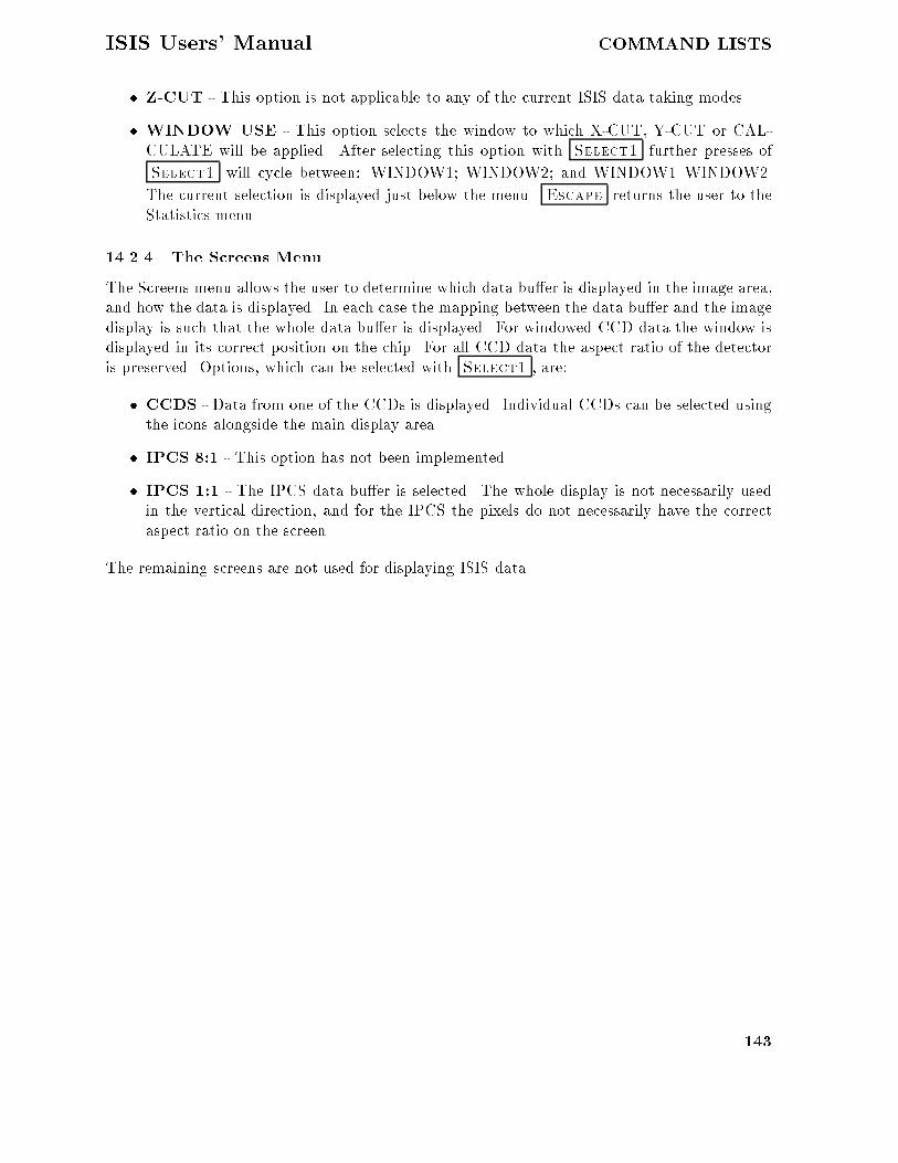
ISIS Users� Manual COMMAND LISTS
� Z�CUT � This option is not applicable to any of the current ISIS data taking modes�
� WINDOW USE � This option selects the window to which X�CUT� Y�CUT or CAL�CULATE will be applied� After selecting this option with Select� further presses of
Select� will cycle between� WINDOW�� WINDOW�� and WINDOW��WINDOW��
The current selection is displayed just below the menu� Escape returns the user to theStatistics menu�
������ The Screens Menu
The Screens menu allows the user to determine which data bu�er is displayed in the image area�and how the data is displayed� In each case the mapping between the data bu�er and the imagedisplay is such that the whole data bu�er is displayed� For windowed CCD data the window isdisplayed in its correct position on the chip� For all CCD data the aspect ratio of the detectoris preserved� Options� which can be selected with Select� � are��
� CCDS � Data from one of the CCDs is displayed� Individual CCDs can be selected usingthe icons alongside the main display area�
� IPCS ��� � This option has not been implemented�
� IPCS ��� � The IPCS data bu�er is selected� The whole display is not necessarily usedin the vertical direction� and for the IPCS the pixels do not necessarily have the correctaspect ratio on the screen�
The remaining screens are not used for displaying ISIS data�
���

APPENDICES ISIS Users� Manual
Part VII
APPENDICES
A Properties of the ISIS Gratings
In this appendix the properties of the ISIS gratings are presented in graphical form� the gratingsetting� slit to detector reduction factor� vignetting factor� and reciprocal dispersion ��A�mm�are presented as a function of wavelength for all red and blue gratings� For completeness graphsfor both blaze�to�collimator and blaze�to�camera are presented� although only use of the formeris recommended� and graphs for grating H���B in the red arm are also presented� although thisis not a particularly e�cient combination� The explanation and the program used to generatethe plots are due to C�R� Jenkins�
The grating equation is
sin i� sin r � ��d
for a �rst�order spectrum� The camera�collimator angle in ISIS� �� is nominally ��� althoughthe exact value will be slightly di�erent for each channel�
i� r � �
�with appropriate sign conventions for i and r�� Solving these two equations gives�
sin i ��
d� sin �
��� � cos ��
s��� � cos ��� ��
d�
where the positive sign corresponds to the normal condition for ISIS� namely blaze to collimator�The grating setting for each channel is then given by multiplying i �in degrees� by ��� and addingan o�set �which is the autocollimation angle for each grating mount�� These o�sets are �� �� forthe blue channel and ��� for the red� In solving for the grating setting� one has to check forthe cases where the angle of incidence exceeds ���� or where the discriminant becomes imaginary�corresponding to the wavelength where constructive interference cannot be achieved��
The reduction factor follows simply� it is�
cos r
cos i
fcollfcam
where fcoll is ��� mm and fcam is �� mm�
The gratings in ISIS are ��� � �� mm�� and the cameras have su�cient apertureto accommodate the fully dilated ��� mm beam� Most of the vignetting �excluding re�nementsof matching central obstructions between camera and telescope pupil� occurs simply becauselight misses the grating at high angles of incidence� The fractional loss is�
v ��� � sin ��
�
where � is given by�cos� � ������ cos i
���

ISIS Users� Manual APPENDICES
This internal vignetting only exceeds �� for the ���� and ��� gratings�
The dispersion is given by�
$�
$s�
d cosr
fcam
���

APPENDICES ISIS Users� Manual
B Grating and Detector E�ciencies
This appendix presents laboratory measurements of the e�ciencies of the ISIS gratings and ofthe CCD and IPCS detectors in use on ISIS�
���

ISIS Users� Manual APPENDICES
C E�ciency of Dichroics and Polarisation optics
This appendix presents laboratory measurements of the transmission properties of the �ve mainISIS dichroics� and measurements made using the comparison lamps on the spectrograph� of thee�ciency of two reddest dichroics in both transmission and re�ection� The �nal panel of thisappendix shows the throughput of the polarization optics �half� and quarter�wave plates andthe Savart plate� measured with the comparison lamps�
��


APPENDICES ISIS Users� Manual
D Details of Neutral Density Filters
This appendix gives the actual values of the densities of ND �lters in both the star�beam��MAINFILTND�� and in the calibration�lamp beam ��COMPFILTA�B���
Table ��� ND values of ISIS�FOS Main�Beam Filters � mm diameter�
Nominal ND ��� ��� ��� ��� ��� �� �� ��� ������A�
���� ��� ��� �� ���� ���� �� ���� ���� ������ �� �� ���� ���� ���� ��� ���� ��� ������� �� ��� ���� ��� ���� �� ��� ���� ������ ��� ���� ���� ��� ���� �� ���� ���� ������ ���� ���� ��� ���� ��� ��� ���� ���� ������ ��� ��� ��� ��� ���� �� �� � ���� ������ ���� ��� ��� ��� ���� ��� ��� ���� �������� ���� ��� ��� ���� ���� ��� ���� �� ��� ��� ���� ���� ��� ���� ���� ���� ��� �� � �������� ���� ���� ���� ���� ���� ���� ��� ���� �� ��� ��� ���� ���� ���� ��� ���� �� ���� ���� ��� ���� ���� ���� ��� ���� ��� ��� ��� ���� �� ���� ���� ���� ���� ���� ���� ��� ���� �������� ���� ���� ���� ���� ���� ��� �� ���� ���
Table ��� Neutral Densities of ISIS�FOS Calibration�Beam Filters ��mm diam�
Nominal ND ��� ��� �� ��� �� ��� ��� �� ��� ������A�
���� ��� ��� �� ��� �� � �� � ���� ���� ���� ������� ��� �� �� �� �� ���� ���� ��� ��� ������� ���� �� ��� ��� �� � ���� ���� ���� ���� ������� ���� ��� �� ���� ���� ���� ���� ���� ���� ������ ���� ���� ��� ���� ���� ��� ��� ��� ���� �� ��� ��� ��� ��� ���� ���� ��� ���� �� � ���� ����� ��� ���� ��� ���� �� � ��� ���� ���� ��� �������� ���� ���� ��� ���� �� ��� ���� ���� �� � ������� ���� ���� ��� ���� �� � ��� ���� ��� ���� ������� ���� ���� ��� ���� �� � ���� ���� ��� ���� �� ��� ���� ��� ��� ���� �� ���� ��� �� ���� ��� ��� ���� ��� ��� ���� �� ���� ��� ��� ��� ���� �� ���� ���� ��� ���� �� � ���� ���� ��� ���� �������� ���� ���� ��� ��� �� � ���� ���� ��� �� ���
���

ISIS Users� Manual APPENDICES
E Details of the La Palma Sky
E�� Sky Brightness and Spectrum
Typical sky brightness at La Palma� in mags per square arcsec� are given below� in �dark�� �grey�� �bright� time� These data refer to clear conditions �no cloud or dust� low aerosols� extinctionat V between ��������� mag�airmass��
Table ��� La Palma Sky Brightness �Mag�Square Arcsec�
U B V R I Moon Data Source
��� ���� ��� ��� ���� Dark JKT�Peoples Photometer� June ��
���� ��� ��� ��� ��� Dark JKT � CCD June�September �� ����� ���� ���� ���� ���� Grey � ���� ��� ���� ��� ���� Bright � �
In the Table� �Dark� means Moon below the horizon� �Grey� means above thehorizon with phase �� ������ and �bright� means above the horizon with phase ���������� Thesky data are guidelines� precise values depend critically on angular distance from the Moon� theelevation of the Moon� and the atmospheric aerosol � dust content�
The dark�sky variation between �� �� may be partly due to a correlation withphase of the ���year Solar cycle� a variation of ��mag has been reported by the UK SchmidtTelescope� but because of the lower geomagnetic latitude of La Palma a slightly smaller ampli�tude is expected here�
Flux�calibrated� low�resolution night sky �airglow� spectra have been presentedby C�R� Benn �Gemini� ��� p ��� ����� and by C� Jenkins � S� Unger �ING La Palma TechnicalNote No ��� Note that in the red� emission lines from OH and H�O molecules dominate thespectrum� and so the broad�band magnitudes given above do not give a good idea of the skycontinuum �ux at any particular wavelength�
E� Extinction at La Palma
The extinction as a function of wavelength has been tabulated by D�L� King �ING Tech Note No���� a data �le and interpolation program are stored in the %LPINFO& directories at Cambridgeand La Palma� These data are valid only for a very clear night with low aerosol content� andcorrespond to an extinction of ����mag�airmass in the �V� band� �A value of ��� is more typical�and values above ��� will usually include a contribution from dust�� The actual extinctionfor any �clear� night can be obtained from the Carlsberg Meridian Circle data �also stored in%LPINFO&�� and for values at �V� between ��� � ����� the extinction curve usually has the sameshape as King�s curve�
The King extinction curve is repeated here� m is the value in magnitudes perairmass� Note the low value at ���A�
Sahara dust can extinguish starlight and re�ect light from the Moon and street�lamps� Although it is thought normally to be grey in extinction at optical wavelengths �D� Jones�Tech Note No �� � D� Stickland et al�� Observatory� ��� �� �� ��� very non�grey extinction hasbeen reported once �Andrews � Williams� ibid� ���� �� �� ���
���

APPENDICES ISIS Users� Manual
Table �� La Palma Standard Extinction Curve
� m � m � m
���� ����� ��� ������ �� ��������� ����� �� ����� �� ���������� ����� ��� ��� � ��� ���������� ������ ���� ��� �� ��� �������� ���� ���� ��� �� ����� ��� ���� ���� ������ ��� ���������� �� ���� ������ ���� ����� ���� ����� ��� ����� ���� ������� �� ������ ��� ���� ���� ���������� ������ ���� ���� ���� �������� ����� ���� ����� ��� ��������� ����� � �� ���� ��� ���� ���� ������ ���� ���� � ���� ���� ���� ����� ���� ����� ���� ���� ��� ���� � ���� ������ � �� �������� ��� �� ���� ������ ���� �������� ����� ���� ���� � ����� ��������� ����� ��� ����� ����� ����� �� ���� ��� ���� ����� �������� ������ ���� ������ ����� ��������� ���� ���� ������ ���� ��������� ������ � �� ������ ���� ���� ��� ������ ���� ���� � ����� �������� ���� � ��� ����� ����� ������ ����� ��� ����� �� �� ������� ������ ��� ����� ����� �������� ������ ��� ����� ����� ����
���

ISIS Users� Manual APPENDICES
F The LAPLATE program�
The programme LAPLATE is a modi�cation of the programme APLATE Starlink User NoteSUN ��� developed at the Anglo�Australian Observatory �AAO��
This programme converts a list of equatorial coordinates �right ascension anddeclination into focal plane positions �X and Y�� for the �bre masks for the WHT�
LAPLATE runs starting from a user input �le� This includes several parametersused by the programme and the equatorial coordinates of the observed objects�
The programme takes into account e�ects of precession and nutation of the rota�tional orientation of the �eld� for this� the equinox and observing date must be included in theinput �le� The e�ects of thermal contraction and expansion of the brass aperture plate are alsoconsidered� then� the input �le must include information about the drilling temperature and theobserving temperature� Though di�erential refraction e�ects cannot be calculated in advance�LAPLATE makes a �rst order correction using the zenith distance at which the �eld crosses themeridian� Regarding this last point� APLATE di�ers from LAPLATE because the latter usesthe latitude of the La Palma Observatory�LAPLATE Input �le�
The following is an example for an input �le ��DAT� for the LAPLATE pro�gramme�
M� WHT�Aux
�ARCMIN
D ������
E �����
S ����������
O ����
X ��������
T ��������
C � � ������ ��� �� ��
F � � ����� ��� �� ���� GS
F � � ����� ��� �� ���� GS�
F � �� ������ ��� �� ����� GS�
F � �� ���� ��� �� ���� GS
P � � ������ ��� � ���� X
P � � ����� ��� � ���� ��
P � � ����� ��� � ���� ��
P � � ����� ��� �� ���� �
P � � ��� ��� �� ���� �
P � � ���� ��� � ���� � �
As can be seen� in this �le each line starts with a keyword� Each keyword de�nesthe data type given to the program� A brief description is provided below�
L is the plate label� Normally� the plate label will be the observed �eld� Thislabel can contain up to � characters� It must identify clearly the �eld to avoid confusion inthose cases where other �bre observing programmes use similar sky regions�
��ARCMIN de�nes the telescope �eld diameter� With the aid of this informa�tion� the programme checks if all the objects are on the telescope �eld� however� this commandconcerns the Anglo�Australian telescope and� actually� is has not been modi�ed to be used for
���

APPENDICES ISIS Users� Manual
the La Palma telescopes� Then� the information obtained from this command is useless in thiscase�
D is the observing date in decimal years� This is required in order to correctfor the rotational e�ects of precession and nutation� But� as this correction is a rotationalcorrection� the plates can be used again at a later date �if the objects have no large proper mo�tions�� The rotational correction in this case is made adjusting the rotator and plate orientations�section �������
E is the reference equinox for the objects equatorial coordinates� Also� this willbe used to correct rotational e�ects�
S is the focal plane scale in units of ��mm�� This value depends on the telescopeand the telescope focal plane used�
T are two temperature value� the drilling temperature and an estimation of theobserving temperature� These are used to correct e�ects of expansion or contraction of the brassaperture plate� Default values for these temperatures will be �� and degrees�
C is for the equatorial coordinates of the centre of the observed �eld� The tele�scope will be pointed to this position on the sky�
X is to insert two extra �ducial positions at the speci�ed distances �in arcsec�from the nominal plate centre� In the example� these positions are the plate centre and a point�� arcsec North� These holes are employed to connect the semi�coherent guiding bundles to beused for the rotator adjusting� In general� the plates must have two extra �ducial holes� one ��arcsec North from the plate centre and another one �� arcsec South�
F corresponds to the �ducial objects positions� These are the equatorial coordi�nates of the guide stars� A �ducial object position must be speci�ed in the following format�
F right ascension declination equinox commentsEach equinox and comment are optional arguments� The equinox must be spec�
i�ed if the object position is referred to a di�erent equinox from the one de�ned in the Ecommand�
P are the positions for the targets� with a similar format to that used for the�ducial objects�
P right ascension declination equinox commentsA point ��� will be added on the line next to the last line containing positional
data� This point indicates the end of �le for the LAPLATE programme� After this ending point�other useful information not relevant for the programme� can be added�LAPLATE Output �le�
What follows is an example for an output �le ��LOG� for the LAPLATE pro�gramme� It contains the corresponding output for each input parameter in the input �le �as forthe example shown before�� and in the same order�
Comments on the Output �le�
� The �rst line is a warning message because the focal plane scale used is not the defaultone provided by the programme� This message is not important as LAPLATE uses thefocal plane scale speci�ed by the user�
� The date refers to the time at which the data are processed�
��� WARNING � Unusual plate scale � ���
Date� ������ ��
���

ISIS Users� Manual APPENDICES
�� Label� M� WHT�AUX ��
Plate Field� � arcminute Observers���������������������������
Plate Scale � ���� arcsec�mm Observing date����������������������
Temperatures� Fibre Bundle������������������������
Observe at � C� Comments����������������������������
Drilling at �� C ������������������������������������
Julian Epoch Observn������ ������������������������������������
Rotator Position Angle� �����
Equinox of Position �����
Plate Centre� R�A� DEC�
� � ����� � �� � ��
� Fiducial Objects
Fibre Hole R�A� DEC� X Y
� � � ����� ��� � ��� HC�X ������� ������
�� � �� ����� ��� �� ��� HSC���� ����� ������
�� � �� ����� ��� �� ��� HSC�X� ���� ����
� � � ����� ��� � �� � �� N ����� �����
�� � � ����� ��� �� ��� � ��� N ���� ������
� Programme Objects
Fibre Hole R�A� DEC� X Y
�� � � ���� ��� �� ��� GS� ������ ����
�� � � ���� ��� �� ���� X� ���� ������
�� � � ���� ��� �� ���� X� ��� �����
�� � �� ���� ��� �� ���� X� ��� ������
�� � �� ���� ��� �� ��� X� ���� ������
� � �� ���� ��� �� ���� X� ���� �������
�� � �� ��� ��� � ��� X� ����� �����
�� � � ���� ��� � ��� �� ������� ����
� � � �� ��� �� ���� � ������ ����
�� � � ���� ��� � ��� � ������ ����
� � � HOLE � FIBRE CROSS CHECK � � �
Plate Label� M� WHT�AUX
APLATE Date� ������
Observers�����������������������������������������������������������
Observing Date������������������������������������������������������
��

APPENDICES ISIS Users� Manual
Comments������������������������������������������������������������
��������������������������������������������������������������������
��������������������������������������������������������������������
Fibre Bundle����������
�������� ��������� ��������� �������� ���������
�������� ������� �������� �������� �������
��������� �������� ��������� ��������� ��������
��������� �������� ��������� ��������� ��������
�������� ������� �������� �������� �������
��������� �������� ��������� ��������� ��������
��������� �������� ��������� ��������� ��������
��������� �������� ��������� ��������� ��������
��������� �������� ��������� ��������� ��������
��������� �������� ��������� ��������� ��������
� Gives the value of the input �le commands�
� Gives the coordinates of the �eld centre for telescope pointing�
� Gives information about �ducial objects� equatorial coordinates �R�A� DEC�� �ducialobject label and calculated plate position �X� Y� in millimetres from the plate centre�
� Gives information about the targets� equatorial coordinates �R�A� DEC�� object label andcalculated plate position �X� Y� in millimetres from the plate centre�
� The number shown at the end of the output �le will be used to assign each �bre to thecorresponding hole� by means of the object labels�
���


![Instrumen project[1]](https://static.fdocuments.in/doc/165x107/589f91761a28ab1b198b56ab/instrumen-project1.jpg)