is.6848.1979
31
Indian Standard SPECIFICATION FOR LEAD-ACID BATTERIES FOR TRAIN LIGHTING AND AIRCONDITIONING SERVICES IS :6848- 1979 ( First Revision ) Second Reprint AUGUST 1993 UDC 621’355’2 : 628’977’8 : 625’2 Q Copyrfght 1980 BUREAU OF INDIAN STANDARDS MANAK BHAVAN, 9 BAHADUR SHAH ZAFAR MARG NEW DELHI 110002 Gr 6 February 1980
description
info
Transcript of is.6848.1979
Indian Standard SPECIFICATION FOR
LEAD-ACID BATTERIES FOR TRAIN LIGHTING AND AIRCONDITIONING SERVICES
IS :6848- 1979
( First Revision )
Second Reprint AUGUST 1993
UDC 621’355’2 : 628’977’8 : 625’2
Q Copyrfght 1980
BUREAU OF INDIAN STANDARDS MANAK BHAVAN, 9 BAHADUR SHAH ZAFAR MARG
NEW DELHI 110002
Gr 6 February 19 80


IS : 6848 - 1979
Indian Standard SPECIFICATION FOR ,
LEAD-ACID BATTERIES FOR TRAIN LIGHTING AND AIRCONDITIONXNG SERVICES
( First Revision )
0. FOREWORD
0.1 This Indian Standard ( First Revision ) was adopted by the Indian Standards Institution on 27 June 1979, after the draft finalized by the Secondary Cells and Batteries Sectional Committee had been approved by the Electrotechnical Division Council.
0.2 This revision of the standard has been undertaken in view of the latest development in this field. Some test methods have been so modified that they will facilitate the testing of batteries under conditions that are closer to the actual working conditions. Two additional capacity tests at 5 and 3 hour discharge rates have been added.
0.3 This standard deals with the lead-acid storage batteries used in train lighting and airconditioning services.
0.4 The batteries are required to meet the power demand of the lights, fans and airconditioning equipment of the coaches during halts or slow running.
0.5 The supplier shall furnish information on proformae given in Appendices A and B while submitting tender.
0.6 Appendix C describes the service tests for information. If this test is to be performed, it shall be agreed to between the supplier and the purchaser.
0.7 Unless otherwise specified by the purchaser, for each set of 12 cells of 24 V battery, 10 inter-cell connectors and 4 battery end-cell connectors along with their fasteners shall be supplied. For 56 cells of 110 V battery, 104 intercell connectors and 16 battery end-cell connectors along with their fasteners shall be supplied.
0.8 In the preparation of this standard assistance has been drawn from the following publications:
XEC Publication : 77 * ( 1968 ) Rules for electric traction equipment. International Elecerotechnical Commission.
3
--v----- ‘-. ” --” %’

IS : 6848 - 1979
t 1
.s c 1
a
:r n n
I5 Jl
ne ,a\
.ot
‘gY ne
on
ich
Yt=
Cd
3. MATERIALS AND CONSTRUCTION
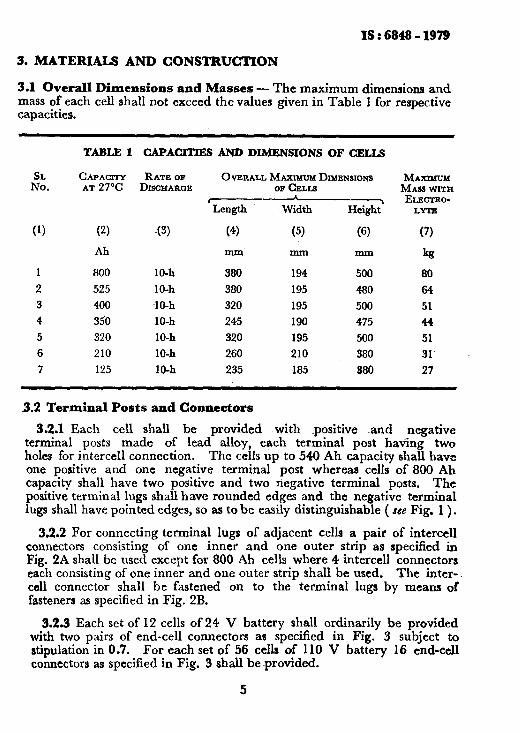
3.1 Overall Dimensions and Masses - The maximum dimensions and mass of each cell shall not exceed the-values given in Table 1 for respective capacities.
SL No.
(1)
TABLE 1 CAPACITDB AND DIMENSIONS OF CELLS
CAPACITY RATEOP 0 VERALL MAXXMUM DIMENSIONS AT 27°C DISCHARGE OFCELLS
--- Length Width Heightl
(2) X3) (4) (5) (6)
Ah mm mm mm
800 10-h 380 194 500
525 10-h 380 195 480
400 10-h 320 195 500
350 10-h 245 190 475
320 10-h 320 195 500
210 10-h 260 210 380
125 10-h 235 185 380
MAXIUUM MASSWITH ELECIX~- LYTJS
(7)
kg
60
64
51
44
51
31’
27
.
3.2 Terminal Posts and Connectors
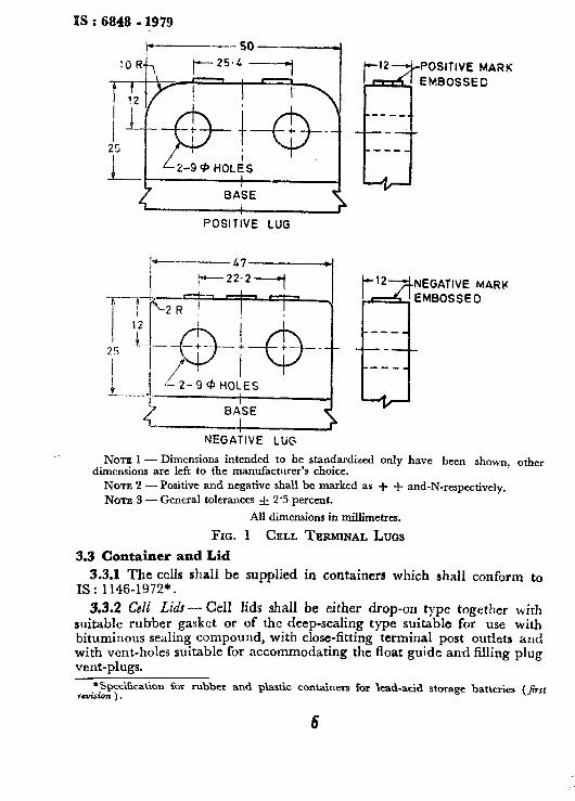
3.2.1 Each cell shall be provided with positive -and negative terminal posts made of lead alloy, each terminal post having two holes for intercell connection. The cells up to 540 Ah capacity shall have one positive and one negative terminal post whereas cells of 800 Ah capacity shall have two positive and two negative terminal posts. The positive terminal lugs shall have rounded edges and the negative terminal lugs shall have pointed edges, so as to be easily distinguishable ( see Fig. 1 ).
3.2.2 For connecting terminal lugs of adjacent cells a pair of intercell connectors consisting of one inner and one outer strip as specified in Fig. 2A shall be used except for 800 Ah cells where 4 intercell connectors each consisting of one inner and one outer strip-shall be used. The inter-, ccl1 connector shall be fastened on to the terminal lugs by means of fasteners as specified in Fig.; 2B.
3.2.3 Each set of 12 cells of 24 V battery shall ordinarily be provided with two pairs of end-cell connectors as specified in Fig. 3 subject to stipulation in 03. For each set of 56 cells of 110 V battery 16 end-cell connectors as specified in Fig. 3 shall beprovided.
*
. .
i .
. i ,.’
I,
u
,.
,
.
‘.
i
h
IS : 6848 - 1979
POSITIVE LUG
POSITIVE MARK
EMerOSSEO
NEGATIW MARK
NEGATIVE LUG
Nom 1 - Dimensions intended to be standardized only have been shown, other dimensions are left to the manufacturer’s choice.
NOTE 2 - Positive and negative shall be marked as + + and-N-respectively, NOTE 3 - General tolerances f 2.5 percent.
All dimensions in millimetres.
FIG. 1 CELL TERMINAL LUGS
3.3 Container and Lid
3.3.1 The cells shall be supplied in containers which shall conform to IS : 1146-1972”.
3.3.2 Cell Lids - Cell lids shall be either drop-on type together with suitable rubber gasket or of the deep-sealing type suitable for use with bituminous sealing compound, with close-fitting terminal post outlets and with vent-holes suitable for accommodating the float guide and filling plug vent-plugs.
*Fjpecification for rubher and plastic containers for lead-acid storage batteries (J;rs, rmision ) .
32.3 #hall be
3.3.4 for vtnti the anti allow the
Nom form to
Nom ‘bend1
NOTI
NOTE for cell
Nonr
+SpeCi6 engineeriq

ther
3.3.3 Suitable separator guard of acid resisting and insulating material shall be provided.
3.3.4 ht-Plug - Each cell shall be provided with adequate means both for venting and for servicing of thewolyte. The vent-plug shall be of the anti-splash type, preferably with more than one exit hole, and shall allow the gasca to escape freely but shall effectively prevent acid particles or spray from coming out. On removal of vent-plug drawing of the electrolyte samples, servicing and checking of the electrolyte level shall be possible.
TO BE PUNCHED
NEGATIVE END
ALUMINIUM STRIP
POSITIVE END
MIN LEA0 COATING THICKNESS 0.075
NOTE 1 - Aluminium used in the manufacture of the intercell connectors shall con- form to IS : 737-1965* IS designation SIB or SIC.
I to
vith vith and ,lug
NOTE 2 -Cell connector before lead coating to be in ‘0’ condition as specified in ‘ bend test ’ of 10.3.2 of IS : 737-1965*.
NOTE 3 - Lead coating thickness shall be measured in accordance with Appendix F.
None 4 -- Each pair of intercell connectors shall be used ih conjunction with fastener for cell connector ( see Fig. 2B ).
Nom 5 -Edges should be free from burrs.
Wpeciaication for wrought aluminium and aluminium alloys, sheet and strip ( for general engineering purposes ) ( revised ) .
All dimensions in millimetres.
2A Lead Coated Intercell Connectors
FICL 2 INTERCELL CONNECTORS ANDFASTENERS-Co&
7
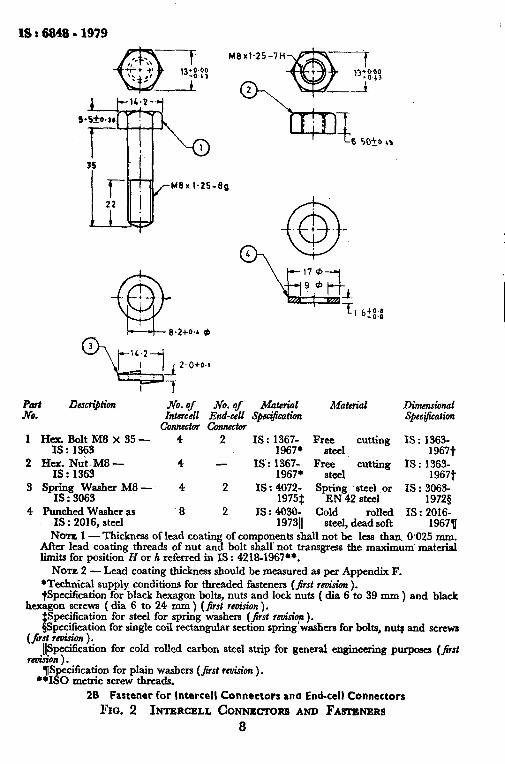
;ct Dmri#ion No. of .No. of Material Material Dimensional
Intercell End-cell S$$t%atinn connectol co7meti
Spec@cation
1 Hex.BoltM8x35- 4 2 IS: 1367- Free IS : xsps 19671 steel
cutting IS : 1363- 1967t
2 HyS Nu;3M8 - 4 - IS: 1367- Free 1967* steel
cutting IS: 1363- 1967t
3 SpIp30y3asher M8 - 4 2 IS : 4072- S~g%~2s;;$ or IS : 3063- : 1975i 19728
4 Punched Washer as 8 2 IS: 4030: Cold rolled IS : 2016: IS : 2016, steel 197311 steel, dead soft 19678
NOTE 1 - Thickness of lead coating of components shall not be less than O-025 mm. After lead coating threads of nut and bolt shall not transgress the maximum material limits for position H or h referred in IS : 421%1967**.
NOTE 2 - Lead coating thickness should be measured as per Appendix F. *Technical supply conditions for threaded fasteners (first renti ). +$cci&ation for black hexagon bolts, nuts. and lock nuts ( dia 6 to 39 mm ) and black
hT screws (dia 6 to 24 F) (first rcmnon). peuficanon for steel for sprmg washers (first re&iop ). pecification for single coil rectangular section
(fist cwision ). spring washers for bolts, nu$ and screws
&+Gfication for cold rolled carbon steel strip for general engineering purposes (&t fmision).
T(Specification for plain washers (Jirst rcuision ) . **IS0 metric screw threads.
2B Fastener for Intercell Connectors and End-ceil Connectors
FIO. 2 INTERCELL CONNJKSORS AND FASTENERS 8

b---F4
Battery POklTity Area of Cable Dia Dia capan’ty C?OSS *0.13 *0*13 *:9
B K c
.AH Section mm’
800 & 350 Positive 133 810145 17.2 22.0 26.5 26.5 33.5 14.6 25.4 84.5 806 & 350 Negative 133 8101.45 17.2 22.0 26.5 26.5 33.5 17.8 22.2 :: 84.5 125 & 210 Positive 170 1912.24 11.6 19 14.6
(0 25.4
125 & 210 Negative ,! 70 19/2’24 11.6 :: 19 :9” 2’: 17.8 22.2 I’f :: :QO. 400 &525 Positive 120 3712.06 14.8 19.6 14.6 25.4 320,400 &525 Negative 120 3712.06 14.8 19.6 2255 zz 3”: 17.8 22.2 ft z:
NOTE 1 - Thickness of lead coating of epd-cell connector shall not be less than 0.025 mm. .After lead coating, threads shall not transgress the maximum material limits for position H or h referred in IS : 4218-1967*.
Nora 2 - Lead coating thickness shall be measured in accordance with Appendix E. No-rx 3 -- The end-cell connectors for 800 Ah and 350 Ah cells shall be of pure electrolytic copper in accordance with
, IS : 1897-1971t. Aiuminium used for the manufacture of end-cell connectors for other ratings shall conform to IS : 5082_ 1969$ Grade E 91 E.
NOTE 4 - Before lead coatings the copper connector shall be in bright annealed condition and the aluminium connec- tor in ‘0’ and ‘EX2’ condition for the barrel and palm respectively.
NOTE 5 - Polarity, size of cable in mm” and maker’s mark shall be punched on flat surface. 120 mms maker.
Example : Negative g
Nom 6 - Unless otherwise mentioned tolerance of f 2.5 percent shall apply. *IS0 Metric screw threads. +Clopper strips for electrical purposes (/irst revision ).
i
IWrought aluminium and aluminium alloys, bars, rods, tubes and sections for electrical purposes.
FIG. 3 LEAD-COATED END-CELL CONNECTOR ( CRIMPING TYPE )

IS : 6848 - 1979
3.3.4.1 Whete the venting system is incorporated in. the float guide, filling plugs may be provided. The filler plugs on removal, shall permit servicing and checking of electrolyte.
3.3.5 Suuling Compound - Sealing compound, if bitumen based,, shall COnform to IS : 3116-1965*.
3.3.6 Float Guide and Float - The float guide shall be removable and of antisplash type, and shall facilitate unrestricted vertical movement of the float stem. The float stem shall have markings ,to indicate-the lowest and highest electrolyte levels permissible. The float assembly shall be suitably designed to prevent acid splash in service.
3.4 Electrolyte
3.4.1 The electrolyte shall be prepared from battery grade sulphuric acid conforming to IS : 266-19617.
3.4.2 The level of the electrolyte shall be that specified by the manufacturer and shall be at least 25 mm above the top edge of the separator.
3.4.3 Up to 525 Ah capacity cells the specific gravity of electrolyte when the battery is in fully charged condition at 27°C shall be between I.210 and I.220 and for cells with caNcity higher than 525 Ah electrolyte speci- fic gravity shall be between I.245 and 1.255. The specific gravity shall be corrected to 27°C using the formula given under 331.2 of IS : 8320-1976#.
3.4.3.1 After a full charge, the specific gravity and temperature of the electrolyte shall be measured and the specific gravity corrected to 27°C using the formula:
SGs, =SGt+0~0007(t-27)
where SG, = specific gravity at 27X,
SGt = specific gravity at PC, and
t = temperature of the electrolyte (JM 5.4.6 ).
3.3 Water - Water intended for storage batteries, confqrlhing to IS : 1069-1964$, shall be added to bring the level of electrolyte to approxi- mately the correct height during the course of testing except whtm specifically stated otherwise. It shall be x added just before the charge or during early part of the charge SO that gassing will thoroughly mix it with the electrolyte.
*Specification for sealing compound for lead-acid batterica. tSpeci6cation for sulplluric acid ( rwticd ) . phm-al rcquircmcn~ and methods of tests for lead-acid ototige bat&a. §Z$~~i6cation for water for rtoragc bat&a ( rmhd).
3.6 any IS :
4. E
10-h
4.2 ! tern1 servi of tl frequ
Ff
and I and accel shall
4.3 T permi
5. TE
5.1 c
5.1,
10
guide, permit
I,, shall
and of t of the tst and suitably
lphuric
by the of the
:c when 1 1.210 : speci- shall be 976$.
e of the :o 27°C
ing to pproxi- t when arge or it with
IS : 6849 - 1979
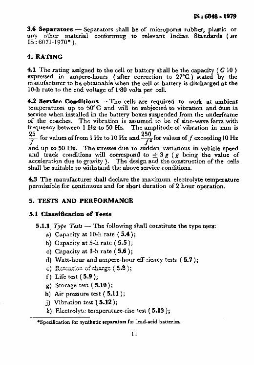
3.6 Separators - Separators shall be of microporus rubber, plastic or any other material conforming to relevant Indian Standards ( see IS : 6071-1970* ).
4. RATING
4.1 The rating assigned to the cell or battery shall be the capacity ( C 10 ) expressed in ampere-hours ( after correction to 27°C ) stated by the manufacturer to be obtainable when the cell or battery is discharged at the 10-h rate to the end voltage of 1.80 volts per cell.
4.2 Service Conditions - The cells are required to work at ambient temperatures up to 50°C and will be subjected to vibration and dust in service when installed in the battery boxes suspended from the underframe of the coaches. The vibration is assumed to be of sine-wave form with frequency between 1 Hz to 50 Hz. Th e amplitude of vibration in mm is
25f f
or values of from 1 Hz to 10 Hz and ?50 for values off exceeding10 Hz f2
and up to 50 Hz. The stresses due to sudden variations in vehicle speed and track conditions will correspond to f 3 g (g being the value of acceleration due to gravity ). The design and the construction of the cells shall be suitable to withstand the above service conditions.
4.3 The manufacturer shall declare the maximum electrolyte temperature permissible for continuous and for short duration of 2 hour operation.
5. TESTS AND PERFORMANCE
5.1 Classification of Tests
5.1.1.
4
b)
c)
4
e)
f ) 9)
h)
j)
Type Teds - The following shall constitute the type tests:
Capacity at 10-h rate ( 5.4);
Capacity at 5-h rate ( 5.5);
Capacity at 3-h rate ( 5.6 );
Watt-hour and ampere-hour eff ciency tests ( 5.7 );
Retention ofeharge ( 5.8 ) ; Life test (5.9 );
Storage test ( 5.10);
Air pressure test ( 5.11);
Vibration test ( 5.12 );
k) Electrolyte temperature-rise test ( 5.13 );
*Specification for synthetic wparators for lead-acid batteries2
I1
I8 t 6848 - 1979
m) Checking of dimensions, mass, markings and workmanship ( 5.14 ); and
n) M.ate.rial and component specification verification test ( 5.15 ).
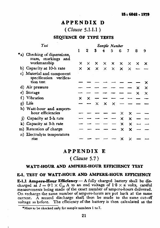
5.x.1.1 S~quenct? of Qpe tests - The sequence of type tests and then number of samples required shall be in accordance with Appendix D.
5.1.X.2 If any of the samples Fails in the relevant type test, the testing authority may call for fresh samples not exceeding twice the original number of ce!ls tested in that particular test and subject them again to the test(s) in which failure occurred. If there is any failure in the retest(s), the type shall be considered as not having passed the requirements of this standard.
5’1.2 Atceptaflce Test
5.1.2.1 The acceptance tests shall be applied on two samples up to a maximum of 1 percent of each type in a lot, the samples being drawn at random by the purchasing or the inspecting authority.
5.1.2.2 The following test shall be conducted as acceptance tests:
a) Ca;jacity test at 10-h rate ( 5.4), and
b) Checking of dimensions, mass, markings and workmanship ( 5.14 ).
5.l.,2.3 Criteria jbfbr acceptance - If any of the sample batteries fails in any of the acceptance tests, twice the original number of samples shall be taken and subjected to all the acceptance tests. If there~is any failure in the retests the lot may be rejected.
5.2 Test Eqdpment - The voltmeters, ,ammeters, thermometers and hydrometers required for the tests specified in this standard shall meet the requirements given in 5.2 of IS : 8320-1976*.
5.3 Temperature for Test - Unless otherwise specified the temperature for tests shall be between 20 and 30%.
5.4 Ttsf k’cw Capacity at l&h Rate
5.4.1 Aftc~ standing on open circuit fnr neither less than 12 hours nor more than 24. hopers from. the completion of a full charge, the bat.tery shall be discharr:ed through a suitable resistance at a constant current I = O-10 x &@I, amperes, and the discharge shall be stopped when the closed circGt voltage acro~ .s the battery terminals fall to l-80 volts per cell.
5.4.2 At this rate of discharge, hourly voltage readings may be taken until the baftery voltage approaches a.‘r,o volts per cell after which the readings &nlI be taken every 15 minuees until the voltage falls to 130 volts i>e” cell. ______- _._..__._ I~ .----
*General requirements nnd methods of tes for Irad-arid storage battetia.
12

IS:6848-1979
5.4.3 The average temperature of the electrolyte taken hourly shall be taken as temperature t”C of the electrolyte during discharge.
5.4.4 On the first discharge, the battery or cell shall give not less than 85 percent of the rated capacity, and the rated capacity shall be reached within 10 disharge cycles subsequent to the initial charge.
NOTE - If as a result of the first test itself the capacity is foundto be equal to or above the rated value, it is not necessary to carry out further tests.
5.4.5 The battery shall be charged at the normal charging rate immediately after the discharge.
5.4.6 The capacity in ampere-hours shall be obtained by multiplying the discharge current by the total time of discharge in hours and the product so obtained shall be corrected to a temperature c ’ 27°C by the following formula:
where
c2, = et
1+X(1-27)
C,, = ampere-hour capacity at an averag 2 electrolyte temperature of 27”C,
Ct A ampere-hour capacity obtained at an aver age electrolyte temperature of PC,
X = correction factor which is equal to 0.0043 for both tubular positive plates and pasted plates, .rnd
t = average temperature of electrolyte during discharge ( mean value of initial and final temperatures ).
5.4.7 The capacity at 10-h rate when tested as in 5.4.p shall be not less than the rated capacrty ( Cl0 ) (se6 Table 1 ).
5.5 Test for Capacity at 5-h Rate
5.5.1 After standing on open circuit for not less than 12 hours but not more than 24 hours from the completion of a full charge, the battery shall be discharged through a suitable resistance at a constant current I = 0.2 C, A where C, = O-83 C,,, and the discharge shall be stopped when the closed circuit voltage across the battery terminals falls to l-75 V per cell.
5.5.2 At this rate of discharge, hourly voltage readings may be taken until the battery voltage approaches 1.9 V per cell after which the readings shall be taken every 15 min until the voltage falls to 1.75 V per cell.
5.5.3 The average temperature of electrolyte taken hourly shall be taken as temperature PC of the electrolyte during discharge.
5.5.4 The battery shall be charged at the normal charging rate immediately after the discharge.
13
IS : 6848 - 1979
5.5.5 The capacity in ampere-hours shall be obtained by multiplying the discharge current by the total time of discharge in hours axiti’the product so obtained shall be corrected to a temperature of 27°C by the formula given under A-5 of IS: 8320-1976*. OfK:
The following shall be the values
K = 0.005 8 for tubular plate = 0.008 4 for pasted plate.
5.5.6 The capacity at 5-h rate when tested as above shall not beless than 83 percent of the rated capacity.
5.6 Test for Capacity at 3-h Rate
5.6.1 After standing on open circuit for not less than 12 hours but not more than 24 hours from the completion of a full charge, the battery shall be discharged through a suitable resistance at a constant current I = 0.33 C, A where Cs 1 O-72 C,,, and the discharge shall be stopped when the closed circuit voltage across the battery terminals falls to l-70 V per cell.
5.6.2 At this rate of discharge, hourly voltage,: readings may be taken until the battery voltage approaches 1.9 V per cell after which the readings shall be taken every 15 min until the voltage falls to 1.70 V per cell.
5.6.3 The average temperature of electrolyte taken hourly shall be taken as temperature t?C of the electrolyte during discharge.
5.6.4 The battery shall be charged at the normal charging rate immediately after the discharge.
5.6.5 The capacity in ampere-hours shall be obtained by multiplying the discharge current by the total time of discharge in hours and the product so obtained shall be corrected to a temperature of 27’C by the formula referred in 5.5.5 with the following values of correction factor K:
K = 0.006 8 for tubular plates = 0.009 1 for pasted plates.
5.6.6 The capacity at 3-h rate when tested as above shall be not less than 72 percent of the rated capacity.
5.7 Watt-Hour and Ampere-Hour Efficient P
Test - Watt-hour and ampere-hour efficiencies when tested and ca culated as described in Appendix E shall be not less than 75 percent and 90 percent respectively.
5.8 Test for Retention of Charge- The object of this test is to determine the loss of capacity of a battery on open circuit during a specified period. -
*General requirements and methods of test for lead-acid storage batteries.
14
5.8.1 Tl manufactu test in act as the me:
5.8.2 A from its su 14 days w.
5.8.3 A with 5.4. by Cl.
5.8.4 A recommen
5.8.5 ‘I from the f
5.8.6 h above, thm capacity.
5.9 Life ’
5.9.1 T obtained 1
5.9.2 T satisfactor
5.9.3 1 and the-s] and, if ne
5.9.4 1
5.9.4 5.9.5 ) th several c( mm shall the cells 2
5.9.4, not more shall be I= 0’10: circuit c?l
IS : 6848 - 1979
5.8.1 The battery shall be fully charged at the current specified by the manufacturer and it shall then be submitted to two consecutive capacity test in accordance with 5.4, the value of initial capacity C being calculated as the mean of the two results thus obtained.
5.8.2 After a complete recharge and after Cleafiing of the electrolyte from its surface, the battery shall be left on open circuit for a period of 14 days without disturbance at a temperature of 27 f 2°C.
5.8.3 After 14 days storage the battery shall be discharged in accordance with 5.4. The value of capacity measured after storage shall be denoted by CI.
5.8.4 After discharge the battery shall be fully charged at the rate recommended by the manufacturer.
5.8.5 The loss of capacity S expressed as a percentage shall be calculated from the formula:
$- C---C’ x 100
5.8.6 Requirement - When tested in accordance with the method specified above, the loss of capacity shall not be more than 10 percent of the initial capacity.
5.9 Life Test
59.1 The life of: battery is defined by the number of life test units obtained under the following conditions.
5.9.2 The life test is carried out on at least three cells which have satisfactorily passed the tests in accordance with 3.1, 5.4 and 5.14.
5.9.3 The battay is to be fully charged. When fully charged, the level and the specific g:avity of the electrolyte of each battery shall be checked and, if necessary, adjusted.
5.9.4 Test Capacity
5.9.4.1 The,battery shall be kept in an air chamber ( see Note under 5.9.5 ) the Emperature of which is maintained at 50 f 2°C. If, however, several cellr are placed in the same chamber, a minimum distance of 25 mm shall h: maintained between them. The minimum distance between the cells ard the sides of the air chamber shall also be 25 mm.
5.9.4.2 After standing on open circuit for not less than 12 hours but nof more than 24 hours from the completion of a full charge, the battery shall be discharged through a-suitable resistance it a constant current I= 0.10 x Cl,, A and the discharge shall be complete when the closed circuit Qltage across the battery terminal falls to 1.80 V per cell.
15
Isr6949-1979
5.9.43 At this rate of discharge hourly voltage reading may be taken until battery voltage reaches I.9 V per cell, after which the reading shall bc taken every 15 minutes until voltage falls to 1.80 V per cell.
5.9.4.4 The capacity in Ah shall be obtained by multiplying the discharge current by the total time of discharge in hours. This capacity shall be called as original test capacity.
5.9.4.5 The battery shall be charged at the normal charging rate immediately after the discharge:
5.9.5 The batteries shall then be subjected to a series of discharges and charges continuously. The dischage shall be for 4 hours at a current of I = 0.25 C,, A. This shall be followed by charge at a current of I = 0.25 C, A for 20 hours.
During the discharging and charging periods,~ them batteries shall be kept in an air chamber ( see Note ) the temperature of which is maintained at 50 f 2°C. If several batteries are placed in tile same chamber, a minimum distance of 25 mm shall be maintained between them. The minimum distance between the batteries and the sider of the air chamber shall also be 25 mm. Distilled or de-ionized water shall be added to the cells daily during the life test to maintain the electrolyte at its normal level. The discharge and charge cycles shall be carried outlive times.
NOTE - Until the air chamber facilities are available witk the manufacturers, the teat may be carried out in a water-bath whose temperature is maintained at 50 ~2%.
5.9.6 After the above cycles of discharges and charm the batteriesshall be kept on open circuit for 24 hours at 50 f 2°C. After this open circuit stand, they shall be test discharged at a rate of 0.1 C,, A. The discharge is continued to an end voltage of 1.80 V per cell. On conpletion of this discharge the battery shall be fully recharged. The combination of discharge and recharge cycles as described above together with 24-hours open-circuit stand period, the test discharge and subsequelt recharge~shall be one unit of life test.
5.9.7 The battery shall be subjected to repeated test units of life test as described in 59.6, until the capacity measured in any test discharge falls to 80 percent of the original tested capacity. The number of li@ units the battery has exhibited shall be recorded.
Norm - The value of percentage of original tested capacity aftex which the life test shall be stopped will be reviewed later when more information is available.
5.9.8 The number of life units is under consideration. NOTE - Till such time the minimum number of life units is incorporated ix the Stan-
dard, such a requirement shall be subject to agreement between the manufaauer and de purchaser.
5.10 Storage Test - The batteries shall be capable of being atorcd unfilled, for a period of 24. months.
16
5.10.: for cas in 5.4.
5.11 Ai the batr HsO. under 1 15 mxo1
5.11.: 87cmf disconti due to I
NU
5.12 W
5.13 El
5.14 Cl ship - conforn visually
a:
b: d
5.15 M The cc manufa various standar compoi from th mcnts
6. MA
6.1 Ms ,details
a: b
c:
IS : 6848 - 1979
:cn all
hC
ity
ite
nd I
be cd a
he er 3e 21.
he
111 lit :e .is of I-S
rll
* 3s
lls le
. st
n- Id
d
5.10.1 After storage for the specified period, t;he batteries shall be tested for capacity at the 10-h rate and shall satisfy the requirements given in 5.4.
5.11 Air Pressure Test (for Leakage ) -The sealing of each cell of the battery shall be checked by compressed air at a pressure equal to 70 cm HsO. The volume of the tubes and auxiliary parts connected to the cell under pressure shall not no exceed 0.5 litre. The air pressure in the cell, 15.seconds after supply has been disconnected, shall be noted.
5.11.1 The air pressure shall not fall from 70 cm Ha0 to below 87 cm H,O within 15 seconds after the supply of compressed air has been discontinued. The cell lid shall not show any visible sign of movement due to the air pressure.
N~TB -T&is .ttst shall be carried out on uniilled cells.
5.12 Vibration Test - Under consideration.
5.13 Electrolytic Tempcratrrre-Rise Test - Under cons&ration.
5.14 Checking of Dimensions, Mass, Markings and Workman- ship -The cells shall be checked to see that the dimensions and masses conform to 3.1 and tha marking is according to 6.1. The cells shall be visually examined for the following:
a) Appearance of the container, that is, watch for cracking or chipping or distortion;
b) Signs of leakage or spillage; and I
c) Appropriate maiking on the battery.
5.15 Material and Component Specification Verification Test - The cell shall be axamined in the dismantled condition to see that the manufacture is to the approved outline and assembly drawing and the various components are conforming to the specification as detailed in this standard and/or declared by the manufacturer. The samples of sealing compound, separator, container and electrolyte shall be taken at random from the manufacturing line and tested to see that they meet the require- mcnts of the relevant specifications.
I I
6. MARKING AND PACKING
6.1 Marking -Both the shorter sides of each cell shall have the following I
details marked on it: I
4 b) 4
Manufacturer’s name or trade-mark, ,
Rating at IO-hour discharge rate, and
Specific gravity of the electrolyte in the fully charged condition at 27 rf: 2°C.
17 I

1s~: 6848 - 1979
6.1.1 The year and month of manufacture shall be punched on the terminal lug base.
6.1.2 The batteries may also be marked with the Standard Mark1
NOTE - The use of the Standard Mark is governed by the provisions of the Bureau of Indian Standards Act, 1986 and the Rules and Regulations made thereunder. The Standard Markon products covered by anIndianStandard conveys the assurancethatthe~ havebeen
produced to comply with the requirements of that standard under a well define2 system of inspection, testing and quality control which is devised and supervised by BIS and operated by the-producer. Standard marked products are also continuously checked by BIS for conformity to that standard as a further safeguard. Details of conditions under which a license for the use of the Standard Mark may be granted to manufacturers or producers may be obtained from the Bureau of Indian Standards.
6.2 The batteries shall be suitably packed so as to avoid any loss or damage during transit.
7. MANUAL OF INSTRUCTIONS
7.1 The manufacturer shall supply one copy of instruction manual for initial treatment and routine maintenance on service, with every batch of batteries ordered.
APPENDIX A
( Clause 0.5 )
SCHEDULE OF
The following particulars facturer with the quotation:
Sl .NO.
1.
2: 3.
4.
5. 6.
7. 8. 9.
Description
Make Type of unit
DESIGN PARTICULARS
are required to be supplied by the manu-
Particulars to be filled in
. . . . . . . . . . . . . . ..a....
..*..................
Manufacturer’s nomenclature Overall dimensions of unit (length x
width x height) Mass per unit with acid Cell container material
Type of positive plates Type of negative plates Separators
18
.....................
............... mm
.................. kg
.....................
.....................
.......................
.....................
ii.
10.
a, 11.
1 12.
l-3.
14.
15.
16.
17.
SI NO.
0.
1.
2.
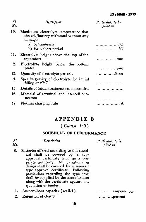
the
of rrd !Wl
of ted for ,a
lay
age
for ~Of
IlU-
Sl NO.
10.
15.
16.
17.
Is : 6848 - 1979
Description Particulars to be jilkd in
Maximum electrolyte temperature that the cell/battery withstand without any damage:
a) continuously “C . . . . . . . . . . . . . . . . . . b) for a short period . . . . . . . . . . . . . . . . . . OC
Electrolyte height above the top of the separators . . . . . . . . . . . . . . . mm
Electrolyte height below the bottom plates . . . . . . . . . . . . . . . mm
Quantity of electrolyte per cell . . . . , , . . . . . . . . .litres
Specific gravity of electrolyte for initial filling at 27°C . . . . . . . . . . . . . . . . . . . . .
~Details of initial treatment recommended . . . . . . . . . . . . . . . . . . . . .
Material of terminal and intercell con- nectors . . . . . . . . . . . . . ...+....
Normal charging rate . . . . . . . . . . . . . . . . . . A
APPENDIX B
( Clause 0.5)
SCHEDULE OF PERFORMANCE
Description Particulars to be filled in
Batteries offered according to this stand- ard shall be covered by a type approval certificate from an appro- priate authority. All variations in design shall be covered by a separate type approval certificate. Following particulars regarding the type tests shall be supplied by the manufacturer along with the certificate against any quotation or tender.
Ampere-hour capacity ( see 5.4 )
Retention of charge
19
........... .ampere-hour
........... .percent

.: ISt684S-1979
SI NO.
Desnipfion
3. Resistance to overcharge
4. Life
5. Storage
6. Ampere-hour ttliciency ( $86 5.7 )
7. Watt-hour efficiency ( see 5.7 )
8. Rise in electrolyte temperature above the ambient air temperature when charged from fully discharged to fully charged condition at normal rate
9. Charge and discharge curves with voltagt;e uersu.s time showing the performance of the cell for discharge at 10-h rate and charge at normal rate
10. Recommendations for a reasonably fast charging method without affecting the manufacturer’s guarantee
APPENDIX C
( Cliause 0.6 )
SERVICE TESTS
C-1. SFXVICE TESTS
Particulars to ba j&d in
............ hours
........... .cyclts
............ ampere-hour
........... .perctnt
.......... ..ptrcen t
“C . . . . . . . . . . , . .
. . . . . . ..*............
. . . . . . . . . . ..*........
C-l.1 On completion of actual service of one year the capacity of battery when tested in the manner prescribed in 5.4 shall be not less than the rated capacity when corrected to standard temperature.
C-l.2 On completion of a minimum of two years actual service but not exceeding 28 months commencing from the date of supply, the capacity of the batteries, when tested~ in the manner prescribed in 5.4 shall be not less than 90 percent of the I ated capacity.
C-l.3 If any of the cells fails to comply with the tests as prescribed above these shall be considered as failure. The terms for replacement shall be as agreed between the manufacturer and the purchaser.
*a) (:
3 ( k) C
4 R 4 E
E-l. T
E-l.1 . charge measur On ret curren voltage
‘Ma:
I9:6848-1979
APPENDIX D (Clause 5.1.1.1 )
SEQUENCE OF TYPE TESTS
Test
*a) Checking of dimensions, mass, markings and workmanship
b) Capacity at 10-h rate
c) Material and component
Sample Number 1 2 s
x x x X x x
---
---
VW-
xx- -- X
---
---
---
---
---
5 6 7 8 9
X
X
X
X
X
X
-
-
-
-
X
-
--
-
-
X
X
X
X
- X
X
X
x x --
l specification verifica- tion test
Air pressure
Storage Vibration
Life
Watt-hour and ampere- hour efficiencies
Capacity at 5-h rate
Capacity at 3-h rate
Retention of charge
Electrolyte temperature rise
4 4 f-1 g) h)
8 W
4 4
--
--
--
x --
APPENDIX ( Clause 5.1)
E
WATT-HOUR AND AMPEREHOUR EFFICIENCY TEST
E-l. TEST OF WATT-HOUR AND AMPERE-HOUR EFFICIENCY
E-l.1 Ampere-Hour Effkiency - A fully charged battery shall be dis- charged at I = O-1 x C,, A to an end voltage of 1.8 x n volts, careful ~measurements being made of the exact number of ampere-hours delivered. On recharge the same number of ampere-hours are put back at the same current. A second discharge shall then be made to the same cut-off voltage as before. The efficiency of the battery is then calculated as the
*Mass to be checked only for sample numberr 1 to 7.
bove x as
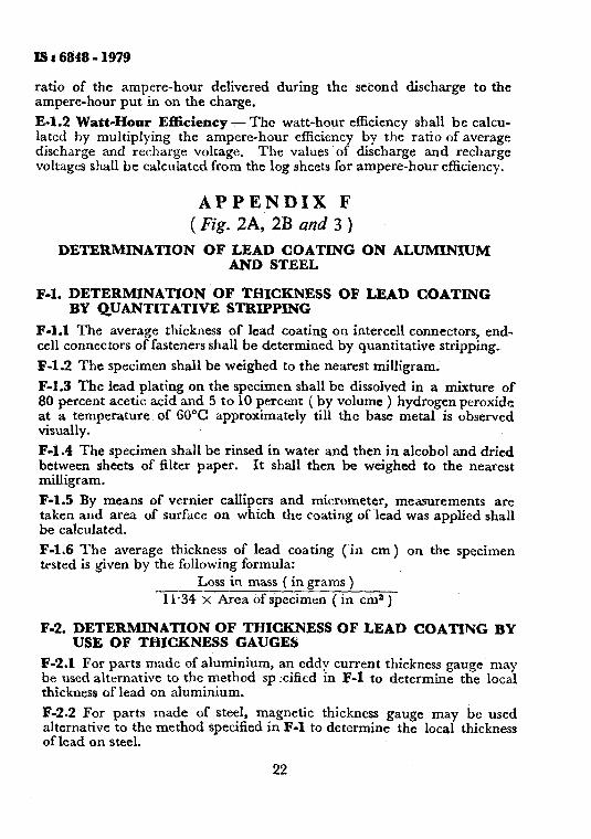
Is t 68’48 - 1979
ratio of the ampere-hour delivered during the second discharge to the ampere-hour put in on the charge.
E-l.2 Watt-Hour Efficiency - The watt-hour efficiency shall be calcu- lated by multiplying the ampere-hour efficiency by the ratio of average discharge and recharge voltage. The values of discharge and recharge voltages shall be calculated from the log sheets for ampere-hour efficiency.
APPENDIX F ( Fig. 2A, 2B and 3 )
DETERMINATION OF LEAD COATING ON ALUMINIUM AND STEEL
F-l. DETERMINATION OF- THICKNESS OF LEAD COATING BY QUANTITATIVE STRIPPING
F-l.1 The average thickness of lead coating on intercell connectors, end- cell connectors of fasteners shall be determined by quantitative stripping_
F-l.2 The specimen shall be weighed to the nearest milligram.
F-1.3 The lead plating on the specimen shall be dissolved in a mixture of 80 percent acetic acid and 5 to 10 percent ( by volume ) hydrogen peroxide at a temperature of 50°C approximately till the base metal is observed visually.
F-l.4 The specimen shall be rinsed in water and then in alcohol and dried between sheets of filter paper. It shall then be weighed to the nearest milligram.
F-l.5 By means of vernier- callipers and micrometer, measurements are taken and area of surface on which the coating of .lead was applied shall be calculated.
F-l.6 The average thickness of lead coating (in cm) on the specimen tested is given by the following formula:
Loss in mass ( in grams ) 11.34 x Area of specimen ( in cmz )
F-2. DETERMINATION OF THICKNESS OF LEAD COATING BY USE OF THICKNESS GAUGES
F-2.1 For parts made of aluminium, an eddy current thickness gauge may be used alternative to the method sp cificd m F-l to determine the local thickness of lead on aluminium.
F-2.2 For parts made of steel, magnetic thickness gauge may be used alternative to the method specified in F-l to determine the local thickness of lead on steel.
22
agah
Claus
‘5 kccel
‘5
tanCi
‘ use rec01
matt
‘5
tYPe
w w test test Ill at

BUREAU OF INDIAN STANDARDS
Headquarters; Mansk Bhavan, 9 Bahadur Shah Zafar Marg. NEW DELHI 110002 Talephones : 331 01 31, 331 13 75 Telegrams : Manaksanstha
( Common to all offices) Regional Oft7ces: Central : Manak Bh8V8n. 9 B8hadur Shah Zafar Mara.
‘Eastern :
Northern :
Southern :
NEW DELHI-110002 1 /14 C.I.T. Scheme VII M, V. 1. P. Road, Maniktola, CALCUTTA 700054 SC0 445-446; Sector 35-C, CHANDIGARH 160036
C. I. T. Campus, MADRAS 600113
tWestern : Manakelaya, E9 MIDC, Marol, Andheri (East), BOMBAY 400093
Branch Offlces: ‘Puahpak’ Nurmohamed Shaikh Marg, Khanpur,
AHMEDABAD 38000-l SPeenya Industrial Area, 1 st Stage, Bangalora Tumkur Road
BANGALORE 560058 Gangotri Complex, 5th Floor, Bhadbhada Road, 1. T. Nagar,
BHOPAL 462003 Plot No. 82/83, Lowis Road, BHUBANESHWAR 761002 6315, Ward No. 29, R. G; Berua Road, 6th Byelane,
GUWAHATI 781003 6-8-66C L. N; Gupta Marg ( N8mp8ffy Station Road),
HYDERABAD 500001
R14 Yudhlster Marg, C Scheme, JAIPUR 302005
117/418 B SarVOd8y8 Nagar, KANPUR 208006
Patliputra Industrial Estate,_ PATNA 800013 T.C. No. 14/1421, University P.O., Palayam
TRIVANDRUM 695035
inspection Oflce (With Sale Point) : Pushpanjali, Tst Floor, 205-A West High Court Road,
Shankar Nagar Square, NAGPUR 440010 Institution of Engineers ( India ) Building, 1332 Shivaji Nagl8r.
PUNE 411005
*Sales Office In Calcutta Is at 5 Chowringhro Approach, P.O. Prlncsp Strrst, Calcutta 700072
?Sales Oftka In Bombay Is at Novelty Chambers, Grant Road, Bombay 400007
$Salrs ORICe In Bangalore Is at Unity Building, Nararlmhara]a ScWrO Iangalorr 560002
Telephones
E 331 01 31 331 1375
36 24 99
1 21843 31641
1
41 24 42m 412519 ’ 41 29 16
6 32 92 96
E 26348 2 63 49
I 38 49 55 38 49 56
6 67 l-6
6 36 27 33177
23 1083
[ 63471 6 98 32
1 21 68 76 21 82 92
62305
1 6 21 04 621 17
2 61 71
62436
27 68 00
89 6128
22 36 71
Prlntrd at Slmco Prlntlna Prooa. Dalhl, IndIn

AMENDMENT NO. 1 APRIL 1985
TO
IS : 6848-1979 SPECIFICATION FOR LEAD-ACID BATTERIES FOR TRAIN LIGHTING AND
AIRCONDITIONING SERVICES
( First Revision )
( Puge 5, Tuble 1, sz Jvo. 7 ) against it.
- Delete together with all entries
( Page 8, Fig. 2, Me 1 ) - Substitute ‘ 0.01 mm ‘for ‘ Ofm mm ‘.
( Page 12, clause 5.1.2 ) - Substitute the following for the existing clause:
c 5.1.2 Acceptance Test-The following tests shall be conducted as icceptance tests:
a) Capacity test at 10 h rate ( 5.4 ) , and
b) Checking of dimensions, mass, markings and workmanship ( 5.14 ).
( Page 12, clause 5.1.2 ) - Add the following new clause after 5.1.2 :
( 5.1.3 Sampling Scheme and Criteria for A~ce@attce
5.1.3.1 A recommended sampling scheme and criteria for the acc:p tance of the lot for various lot sizes is given in Appendix G. ’
(Page 12, clause 5.2 ) - Add the following at the end of the clause:
6 Use of a digital ammeter/voltmeter is preferable for testing. Chart recorders shall be used for life cycle testing. ’
( Page 16, clause 5.9.8 ) - Substitute the following for the existing matter:
‘ 59.8 The number of life units shall not be less than 6. ’
( Page 21, A,bjendix D ) - Add the following Note after sequence of type tests:
‘ NOTE- The cell shall be covered by type approval certificates from an appropriate authority. Significant variations in the design shall be covered by separate type approval certificates. The cell of new design shall be proto-type tested for which samples offered by the manufacturer shall be accepted. For type test samples drawn from mass production at random shall be retested after 5 years. In case of unsatisfactory performance of cells, type testing can be repeated earlier at the discretion of the approving authority. ’
1

( Page 22, A@endix F ) - Add the following as Appendix G after Appendix F:
SAPPENDIX G
( Clause 5.1.3.1 )
SAMPLING SCHEME AND CRITERIA FO;R CONFORMITY
FOR ACCEPTANCE TESTS
Gl. LOT
El.1 All the batteries of the,same type, design and rating manufactured from the same material by the same factory under similar conditions of production shall constitute a lot.
G1.2 The batteries to be selected from each lot shall depend upon the size of the lot and shall be in accordance with co1 (1) and (2) of Table 2:
TABLE 2 SAMPLE SIZE, ACCEPTANCE AND REJECmON NUbfBERS
( Clauses G-l.2 and G-2.1 )
LOT SIZE FIRST STAGE
W) (4 (1) (2)
Up to 50 2 51 ,? 300 3
301 ), 500 5 501 ,, 1000 8
1001 and above 13
SECOND STAGE
(n) (3)
- 5
8 13
ACOEP- TANCE
NUMBER
(24 (4 (4) (5)
2 0 3 0
10 0
16 0 26 0
FIRST REJEC-
TION NUMBER
(rs)
(6)
1 1
2
2 3
SPOOND RNJmo- TION
NUYBEB (rs)
(7)
-
2
2 4
NoTle: I -The sampling plan given in the table envisages that the lota contaiaing about 4 percent defective batteries will be accepted most of the time.
?GOTE 2 -. For lots of size up to 300, the decision regarding acceptance or rejectiin of the lots shall be taken at the first stage only.
Gl..P,1 These batteries shall be selected from the lot at random. In order to ensure the randomness of selection, procedures given in IS : 4905 1968* r:lav be followed.
G-2. NUMBER OF TESTS AND CRITERIA FOR CONFORMlTY
E2.1 A8 the batteries selected at the first stage in accordance with co1 (I ) xm.i (2) of Table 2 shall be subjected to the acceptance tests.
___-.____-- *Methods for random sampling.
A battery failing to satisfy the requirements of any one of the acceptance tests shall be termed as defective. The lot shall be considered as confor- ming to the requirements of acceptance tests if no defective is found and shall be considered as non-conforming to the requirements if the number of defectives is equal to or greater than the first rejection number ( 11 ). If the number of defectives is greater than the acceptance number ( II ) but less than the first rejection number ( rl ), the second sample of the same size as taken in the first stage shall be selected from the lot at random and subjected to the acceptance tests. The number of defectives in the first sample and the second sample shall be combined. If ?the combined number of defectives is less than the second rejection number ( rs ), the lot shall be considered as conforming to the requirements of acceptance tests; otherwise not.
(ETDCII)
3
Printrd at Slmco ?rlntlng Prrro, Dolhl, India
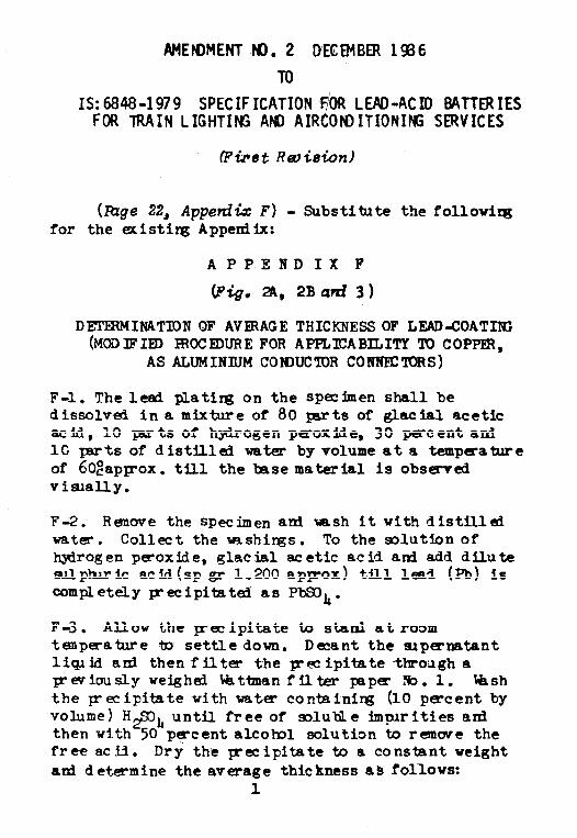
AMENMNT NO. 2 DECEMBER 19B6
TO
IS: 6848-1979 SPECIFICATION FiOR LEAD-ACID BATTERIES FOR TRAIN LIGHTING AND AIRCON)ITIONIffi SERVICES
(Fti8t Rmicrion)
(Rage 22, Apperdix F) - Substitute the following for the existing Appendix:
APPENDIX I"
(Fig. 36, 2Bati 3)
DEYJ!ERMINATION OF AVERAGE THICKNESSOF LEAD-COATIIG (MOi)IFID WOCFDUREFOR APPLICABILITY 'IO COPP,
AS ALUMINIUM CON)UC'IOR CONNECTORS)
F-l. The lead plating on the Specimen shall be dissolved in a mixture of 80 pasts of glacial acetic acid, 10 harts of hydrogen pgoxide, 30 percent ani 1C Iarts of distilled water by volume at a tempeature of 6OzapIrox. till the base material is observed visually.
F&2. Renwe the Specimen-and tarsh it with distilled water. Collect the trRshirgs. To the solution of hydrogen peroxide, glacial aeetic acid and add dilute sulphtric acid(sp gr 1.200 apIrox) till lead (Pb) is completely~ecipitated as PbSDL.
F-3. Allow the ~ecipitate to stand at room temperatie to settledown. Decant the apernatant livid anl thenfilter the pecipitate througha previouslyweighed Wsttatanfilter paper Eo.1. Wsh the p-ecipitate with water containing (10 -cent by volume) H2SDL until free of soluble implrities and then with 50 pgcentalco?ol solution to remwe the freeacid. Dry the precipitate to a constant weight ad determine the average thickness as fOllOWS:
1
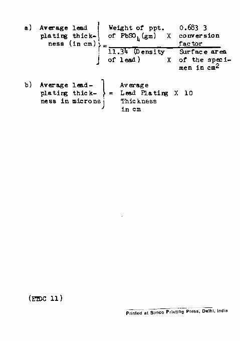
n) Average lead
i
Weight of ppt. 0.683 3 plating thick- ness (in cm)
of ~SJ~(grn) x conversion
=11.34 (Density factor Surface area
oflead) X of the speci- men In cm2
b) Average lcsd- Average platirg thick- = Lead Plating X 10 ness in microns Th'Lckness
in cm
____ Printed at Simco PrintingPress. Delhi, India
AMENDMENT NO. 3 JULY 1988
TO
IS:6848-1979 SPECIFICATION FOR LEAD-ACID BATTWIES FORTRAIN LIGHTING AND
AIRCONDITIONING SERVICES
(First Revision)
(Page 7, clause 3.3.4) - Add the following at the end:
'The vent plug and float guide dia for train lighting cells shall be 27 mm with pitch thread of 3 mm as per IS:4218-1976*. The central hole in float guide and vent plug shall be of 7 mm dia.'
(Page 10, clause 3.4.2) - Substitute the following for the existing clause:
'3.4.2 The height of electrolyte above the top of the separators in fully topped up conditions shall not be less than 40 mm.'
(Page 17, clause 5.12) - Substitute the following for the existing clause:
'5.12 Vibration Test - The test shall be performed i<-a<&%r>a%c<-zG IS:2106(Part 16)-1971t The samples shall be first tested for capacity test was per 5.4, before putting into vibration test. The test consists in vibrating the batteries at a ~frequency of 16 Hz with a total displacement of 5 mm for a period of 2 hours. During vibration the batteries shall be ~discharged at the 10 hour rate.
*ISO Metric screw threads.
+Vibration test.

! 5.12.1 Requirements - There shall not be any sudden drop, either in the current or voltage values and there shall be no spillage of electrolyte during the test?'