IS 5334 (2003): Magnetic Particle Flaw Detection of Welds ... · PDF fileby the Non-destmctive...
10
Disclosure to Promote the Right To Information Whereas the Parliament of India has set out to provide a practical regime of right to information for citizens to secure access to information under the control of public authorities, in order to promote transparency and accountability in the working of every public authority, and whereas the attached publication of the Bureau of Indian Standards is of particular interest to the public, particularly disadvantaged communities and those engaged in the pursuit of education and knowledge, the attached public safety standard is made available to promote the timely dissemination of this information in an accurate manner to the public. इंटरनेट मानक “!ान $ एक न’ भारत का +नम-ण” Satyanarayan Gangaram Pitroda “Invent a New India Using Knowledge” “प0रा1 को छोड न’ 5 तरफ” Jawaharlal Nehru “Step Out From the Old to the New” “जान1 का अ+धकार, जी1 का अ+धकार” Mazdoor Kisan Shakti Sangathan “The Right to Information, The Right to Live” “!ान एक ऐसा खजाना > जो कभी च0राया नहB जा सकता ह ै” Bhartṛhari—Nītiśatakam “Knowledge is such a treasure which cannot be stolen” IS 5334 (2003): Magnetic Particle Flaw Detection of Welds - Code of Practice [MTD 21: Non-Destructive Testing]
Transcript of IS 5334 (2003): Magnetic Particle Flaw Detection of Welds ... · PDF fileby the Non-destmctive...
Disclosure to Promote the Right To Information
Whereas the Parliament of India has set out to provide a practical regime of right to information for citizens to secure access to information under the control of public authorities, in order to promote transparency and accountability in the working of every public authority, and whereas the attached publication of the Bureau of Indian Standards is of particular interest to the public, particularly disadvantaged communities and those engaged in the pursuit of education and knowledge, the attached public safety standard is made available to promote the timely dissemination of this information in an accurate manner to the public.
इंटरनेट मानक
“!ान $ एक न' भारत का +नम-ण”Satyanarayan Gangaram Pitroda
“Invent a New India Using Knowledge”
“प0रा1 को छोड न' 5 तरफ”Jawaharlal Nehru
“Step Out From the Old to the New”
“जान1 का अ+धकार, जी1 का अ+धकार”Mazdoor Kisan Shakti Sangathan
“The Right to Information, The Right to Live”
“!ान एक ऐसा खजाना > जो कभी च0राया नहB जा सकता है”Bhartṛhari—Nītiśatakam
“Knowledge is such a treasure which cannot be stolen”
“Invent a New India Using Knowledge”
है”ह”ह
IS 5334 (2003): Magnetic Particle Flaw Detection of Welds -Code of Practice [MTD 21: Non-Destructive Testing]


Indian Standard
MAGNETIC PARTICLE FLAW DETECTION OFWELDS — CODE OF PRACTICE
(Second Revision )
ICS 77.040.20
0 BIS 2003
BUREAU OF INDIAN STANDARDSMANAK BHAVAN, 9 BAHADUR SHAH ZAFAR MARG
NEW DELHI 110002
October 2003Price Group 2
/

Non-destructive Testing Sectional Committee, MTD21
FOREWORD
This Indian Standard ( Second Revision) was adopted by the Bureau of Indian Standards, after the draft finalizedby the Non-destmctive Testing Sectional Committee had been approved by the Metallurgical Engineering DivisionCouncil.
This standard was first published in 1969 and was revised in 1981 giving detailed requirements about the testprocedure and modifiing the requirements for magnetizing the work-piece. While reviewing this standard, theCommittee decided to revise this standard in order to bring it in line with the present practices being followed inthe country.
In this revision following modifications have been carried out:
a) Scope has been modified;
b) Reference clause has been added;
c) Requirement of surface condition has been modified;
d) Requirement of magnetizing current has been modified; and
e) Requirement of qualified personnel has been added to carry out testing.
For the purpose of deciding whether a particular requirement of this standard is complied with the finalvalue, observed or calculated, expressing the result of a test or analysis, shall be rounded off in accordancewith IS 2: 1960 ‘Rules for rounding off numereicalvalues ( ~evised )’. The number of Sign”iflcantplaces retainedin the rounded off value should be the same as that of the specified value in this standard.

IS 5334:2003
Indian Standard
MAGNETIC PARTICLE FLAW DETECTION OFWELDS — CODE OF PRACTICE
(Second Revision )1 SCOPE
1.1 This standard prescribes the recommendedprocedure for detection of surface and sub-surfacediscontinuities in welds by the magnetic particleinspection method. The method is applicable on”lyto materials in which the weld metal is ferromagnetic.
1.2 Thk standard does not lay down any requirementsfor the acceptance or rejection of welds which shallbe the subject of mutual agreement to between thecontracting parties. This agreement may provide detailswith regard to:
a) welds or sections of welds to be inspected,
b) techniques to be used,
c) type of discontinuities to be accepted, and
d) re-working and subsequent retesting whichmay be permissible.
2 REFERENCES
The following standards contain provisions whichthrough reference in this text, constitute provisionsof this standard. At the time of publication, theeditions indicated were valid. All standards aresubject to revision and parties to agreements basedon this standard are encouraged to investigate thepossibility of applying the most recent editions ofthe standards indicated below:
1S No. Title
3415:1980 Glossary of terms used in magneticparticle flaw detection ( secondrevision )
3703:1980 Code of practice for magnetic particleflaw detection (first revision )
13805:1993 Guidelines for certification forpersonnel for non-destructivetesting
3 TERMINOLOGY
For the purpose of this standard, the definitionsgiven inIS3415 shall apply.
4 PRINCIPLE OF METHOD
This method of flaw detection consists ofmagnetizing the weld and the heat affected zone,
1
applying magnetic particles to the surface andobserving the particle pattern. The particles retainedon the surface due to the leakage field form patternsthat are characteristic of the type of flaws present.This method is suitable for surface and sub-surfaceflaws only and is not suitable for deep-seated flaws,since the sensitivity decreases sharply with the depthof location of the flaws.
S SURFACE CONDIT-ION
The surface to be examined shall be clean, dry andfree from rust, oil, scale, excessive slag and otherextraneous matter which may interfere with thesensitivity of examination. In general, satisfactoryresults may be obtained whemthe surface is in the aswelded condition. However, rough surfaces hamperthe mobility of magnetic particles due to mechanicaltrapping which in turn produces false indications. ‘Insuch cases, surface preparation by wire brushing,sand blasting, grinding, machining or any othersuitable method is necessary. To reveal fine defects,the surfaces to be inspected should be smoothmachined to at least a 6.3 microns finish. However, athin layer of paint of 0.05 mm maximum thickness doesnot interfere with the formation of indications, butmust be removed at points where electrical contactis to be made.
6 TYPES OF PARTICLES
Magnetic particles used for detection of flawsmay be of the dry or wet type in either visible ( colourcontrast ) or fluorescent form.
6.1 If dry particles are used as the examinationmedium, they shall be of high magnetic permeabilityand low magnetic retentivity and shall be of such sizeand shape as will produce suitable indications. It isdesirable that the colour be such as to provide adequatecontrast with the background of the surface beingexamined.
6.2 If wet particles are used, the particles shall bered, black, grey or yellow, or of fluorescent type whenviewed-under ultraviolet illumination. These particleswould be suspended in ‘a liquid medium, the bathstrength of which shall be as given in IS 3703. Thebath shall be thoroughly stirred and the strength( concentration) and condition checked at frequentintervals.

IS 5334:2003
6.3 The dry powder method is more sensitive thanthe wet method in the detection of near surfacediscontinuities, but is less sensitive in detectingfine surface discontinuities. It is also convenient touse in conjunction with _portable equipment for theinspection of large areas or for field operation. It is,therefore, often used for the examination of heavyweldments and parts with rough surfaces. Incomparison, wet method is good for parts with roughsurfaces and for parts which are small in size and testedwith stationary equipment.
7 METHODS OF MAGNETIZATION
A suitable and appropriate means for establishingthe necessary magnetic flux in the job, as describedbelow, may be used.
7.1 Local Circular Magnetization -( or ProdMagnetization )
7.1.1 Local circular magnetization is achieved bythe use of portable prod type electrical contactspressed against the surface in the area to be examined(see Fig. 1).
7.1.2 The prod spacing is usually kept between150-200 mm. Shorter spacing may be used to meetthe limitation of geometry and dimensions of areabeing examined, or to increase the sensitivity, but prodspacing less than 50 mm is not recommended as itwill result into banding of the particles around theprods.
7.1.3 Alternating or half wave rectified magnetizingcurrent shall be used. The current shall be selectedas below depending upon the thickness of the jobsbeing tested:
Thickness Range Current Requirement per25 mm of Prod Spacing
Under 20 mm 90 to 110 ampere
20 mm and over 100 to 125 ampere
7.1.4 A suitable instrument shall be used to measurethe current. The equipment shall be calibrated
periodically once in a year or immediately after it hasundergone major overhaul to ensure that the equipmenthas the required sensitivity and delivers the specifiedcurrent as shown by the ammeter.
7.1.5 In order to avoid damage as a result of burningand to improve the contact efficiency, both test materialand the tip of the electrode must be kept well ground.If necessary, electrodes maybe provided with contactpads. Elimination of arcing isvery important for testinghigh carbon steels and alloy steels as this can causehard spots or cracks.
7.1.6 To eliminate arcing, magnetizing current shouldnot be turned on until after the prods have beenproperly positioned in contact with the surface andthe current shall be turned off before the prods areremoved. For this purpose it is further desirable tohave a remote control switch built into the prodhandles.
7.1.7 Lead or steel-tipped rather than copper-tippedprods are recommended where the magnetizingvoltage is over 25 V,in order to avoid copper penetration.
7.2 Longitudinal Magnetization (Yoke Method )
7.2.1 Alternating current electromagnetic yokes shallbe used provided the sensitivity to detect surface cracksis at least equivalent to that of the prod when a director rectified magnetizing current of 25 to 30 A/25 mmof prod spacing is used and the lifting power of yokeis at least 5 kg with a pole spacing of 75-150 mm.
7.2.2 Alternatively direct current electromagnetor permanent magnet yoke may be used -if it hasgot a lifting power of 20 kg with a pole spacing of75-150 mm, other conditions remaining the same.
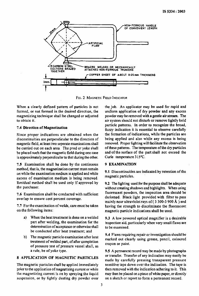
7.3 A suitable instrument, such as magnetic fieldindicator, as shown in Fig. 2 should be used, whenevernecessary, to establishthe adequacy of magnetic field.The indicator should be positioned on the weld beingexamined while applying the required current andferromagnetic particles. The formulation of particlesindicates that adequate field strength has beengenerated in the welding to be examined.
AGNETIZINGCURRENT
FIG. 1 PRODMAGNETIZATION
2
IS 5334:2003
.—NON-FERROUS HANDLEOF CONVENIENT LENGTH
{1
J)
/’8CARBON STEELSECTIONS BRAZED
BRAZED WELOED OR MECHANICALLY
TOGETHERATTACHED NON-FERROUS TRUNIONS
1 rCOPPER SHEET OF ABOUT 0.25mm THICKNES5
FIG.2 MAGNETICFIELDINDICATOR
When a clearly defined pattern of particles is notformed, or not formed in the desired direction, themagnetizing technique shall be changed or adjustedto obtain it.
7.4 Direction of Magnetization
Since proper indications are obtained when thediscontinuities are perpendicular to the direction ofmagnetic field, at least two seperate examinations shallbe carried out on each area. The prod or yoke shallbe placed such that the magnetic field during one caseis approximately perpendicular to that during the other.
7,5 Examination shall be done by the continuousmethod, that is, the magnetization current must remainon while the examination medium is applied and whileexcess of examination medium is “being removed.Residual method shall be used only if approved bythe purchaser.
7.6 Examination shall be conducted with sufficientoverlap to ensure cent percent coverage.
7.7 For the examination of wslds, care must be takenon the following items:
a) When the heat treatment is done on a weldedpart after welding, the examination for thedetermination of acceptance or otherwise shallbe conducted after heat treatment; and
b) The magnetic particle examination after heatt~eatment of welded part, of afier completionof pressure test of pressure vessel shall, asa rule, be of yoke type.
8 APPLICATION OF MAGNETIC PARTICLES
The magnetic particles shall be applied immediatelyprior to the application of magnetizing current or whilethe magnetizing current is on by sp~aying the liquidsuspension, or by lightly dusting dry powder over
the job. An applicator may be used for rapid anduniform application of dry powder and any excesspowder may be removed with a gentle air stream. Theair system should not disturb or remove lightly heldparticle patterns. In order to recognize the broad,fuzzy indication it is essential to observe carefullythe formation of indications, while the particles arebeing applied and also while any excess is beingremoved. Proper lighting will facilitate the observationof these patterns. The temperature of the dry particlesand of the surface of the -part shall not exceed theCurie temperature 315°C.
9 EXAMINATION
9.1 Discontinuities are indicated by retention of themagnetic particles.
9.2 The lighting used for the purpose shall be adequatewithout creating shadows and highlights. When usingfluorescent powders, the inspection area should bedarkened. Black light provided with filter to passmainly near ultraviolet rays of ( 3300-3900 ~ ) andhaving the strength to discriminate the fluorescentmagnetic particle indications shall be used.
9.3 A low powered optical magnifier is a desirableinspection aid, particularly when very small flaws areto be examined.
9.4 Flaws requiring repair or investigation should bemarked out clearly using grease, pencil, colouredcrayon or paint.
9.5 A permanent record maybe made by photographsor transfer. Transfer of any indication may easily bemade by carefully pressing transparent pressuresensitive tape down over the indication. The tape isthen removed with the indication adhering to it. Thismay then be placed on a piece ~f white paper, or directlyon a sketch or report to form a permanent record.
3

IS 5334:2003
10 ASSESSMENT OF FLAWS
10.1 If the indication is caused by the surfacediscontinuities, the particles are usually tightly heldto the surface by a relatively strong magnetic field.The line of particles shall be sharp and well defined.But, if the indication is caused by sub-surfacediscontinuity, the particles are held in a broad fuzzyaccumulation rather than in sharp and well definedpatterns.
10.2 Relevant indications are those which resultsfrom mechanical discontinuities.
10.3 Non-relevant indications are caused by distortionof magnetic field resulting from magnetic writing, coldworking, hard and soft spots, boundaries of heataffected zones, abrupt change of section, etc. Careshall be taken to identify and eliminate them, as theymay mask the actual defects.
10.4 Any indication suggested to be non-relevantis to be considered relevant till it is proved otherwise.
10.5 Broad areas of particle accumulation whichcould mask indications of discontinuities areunacceptable and these areas shall be cleaned andre-examined.
10.6 Linear indications are those in which the lengthis more than three times the width.
10.7 Rounded indications are those which are circularor elliptical with the length less than three times thewidth.
11 DEMAGNETIZATION
11.1 Demagnetization is unnecessary unless theresidual field interferes with subsequent machining,
arc-welding operations, or with structures, such asaircraft, where sensitive electrical instruments maybe affected by the residual magnetic field.
11.2 Demagnetization, if required, shall be clearlyspecified in drawing/purchase orders. The level ofresidual magnetism and the measuring method shallalso be specified.
12 PROTECTION
Since the weld had been cleaned prior to magneticparticle inspection, it is liable to rusting unlessprotected. Temporary corrosion protective may beapplied over the component after magnetic particleinspection.
13 RECORD OF TEST DATA
Magnetic particle flaw detection of welds shall becarried out by qualified personnel ( see IS 13805 ).
13.1 The following data shall be recorded at the timeof each test for further reference:
a)
b)
.C)
d)
e)
o
g)
h)
J)
k)
Name and reference number of the part;
Material sectional thickness, type of weld;
Method used, dry or wet;
Type of magnetization;
Type of current;
Amount of current;
Location and nature of defects;
Details of the machine;
Name and certification level of the operatorconducting the test; and
Other information, if necessary.
4
Bureau of Indian Standards
BIS is a statutory institution established under the Bureau OJ Indian Standards Act, 1986 to promoteharmonious development of the activities of standardization, marking and quality certification of goods andattending to connected matters in the country.
Copyright
BIS has the copyright of all its publications. No part of these publications maybe reproduced inany form withoutthe prior permission in writing of BIS. This does not preclude the free use, in the course of implementingthestandard, of necessary details, such as symbols and sizes, type or grade designations. Enquiries relating tocopyright be addressed to the Director (Publications), BIS.
Review of Indian Standards
Amendments are issued to standards as the need arises on the basis of comments. Standards are also reviewedperiodically; a standard along with amendments isreaffirmed when such review indicates thatno changes areneeded; if the review indicates that changes are needed, it is taken up for revision. Users of Indian Standardsshould ascertain that they are in possession of the latest amendments or edition by referring to the latest issueof ‘BIS Catalogue’ and ‘Standards : Monthly Additions’.
This Indian Standard has been developed from Doc : No. MTD 21 ( 3610 ).
Amendments Issued Since Publication
Amend No. Date of Issue Text Affected
BUREAU OF INDIAN STANDARDS
Headquarters:
Manak Bhavan, 9 Bahadur Shah Zafar Marg, New Delhi 110002Telephones: 23230131,23233375,2323 9402
Regional Offices:
Central: Manak Bhavan, 9 Bahadur Shah Zafar MargNEW DELHI 110002
Eastern: 1/14 C. 1.T. Scheme VI-IM, V. L P. Road, KankurgachiKOLKATA 700054
Northern: SCO 335-336, Sector 34-A, CHANDIGARH 160022
Southern: C. I. T. Campus, IV Cross Road, CHENNA1 600113
Western : Manakalaya,.E9 MIDC, Marol, Andheri (East)MUMBAI 400093
Telegrams: Manaksanstha( Common to all offices)
Telephone
{
2323761723233841
{23378499,2337856123378626,23379120
{603843609285
{22541216,2254144222542519,22542315
{
28329295,2832785828327891,28327892
Branches : AHMEDABAD. BANGALORE. BHOPAL. BHUBAN-ESHWAR. COIMBATORE.FARIDABAD. GHAZIABAD. GUWAHATI. HYDERABAD. JAIPUR. KANPUR.LUCKNOW. NAGPUR. NALAGARH.PATNA. PUNE. RAJKOT. THIRWANANTHAIWMM.VISAKHAPATNAM.
Printed at New India Printing Press, Khurja, India