
Complex discontinuities cascading waveguides models ... · Complex discontinuities cascading...
11
Page 1 of 11 ELECTRICAL & ELECTRONIC ENGINEERING | SHORT COMMUNICATION Complex discontinuities cascading waveguides models studies and analysis Chafaa Hamrouni, Abdessalem Bsissa, Rached Hamza, Adel M. Alimi and Naceur Abdelkarim Cogent Engineering (2016), 3: 1277449
Transcript of Complex discontinuities cascading waveguides models ... · Complex discontinuities cascading...
Page 1 of 11
ELECTRICAL & ELECTRONIC ENGINEERING | SHORT COMMUNICATION
Complex discontinuities cascading waveguides models studies and analysisChafaa Hamrouni, Abdessalem Bsissa, Rached Hamza, Adel M. Alimi and Naceur Abdelkarim
Cogent Engineering (2016), 3: 1277449
Hamrouni et al., Cogent Engineering (2016), 3: 1277449http://dx.doi.org/10.1080/23311916.2016.1277449
ELECTRICAL & ELECTRONIC ENGINEERING | SHORT COMMUNICATION
Complex discontinuities cascading waveguides models studies and analysisChafaa Hamrouni1,4*, Abdessalem Bsissa1, Rached Hamza2, Adel M. Alimi3 and Naceur Abdelkarim4
Abstract: The paper proposes a method for S-matrix generalization to minimize dis-continuities between one-axis rectangular guides in terms of reflection and trans-mission coefficients. We modelate successfully rectangular metal waveguide filters with geometrical and physical discontinuities, and a succession of heterogeneous media such periodic structure and containing Meta materials are presented. Method of S-matrix generalization based on modal development operating by breaking down electromagnetic fields on orthonormal basis for each formed discontinuity. Proposed hybrid method that reference to finite element method incorporation is discussed. We conclude that the Galerkin method application leads directly to the matrix of junction diffraction.
Subjects: Engineering & Technology; Engineering Education; Systems & Control Engineering; Electrical & Electronic Engineering; Electromagnetics & Communication
Keywords: distributed energy generation (DEG); distributed energy storage (DES); demand side management (DSM); energy scheduling and distributed storage algorithm (ESDS); in-Home Energy Storage (iHES); DER distributed energy resources
*Corresponding author: Chafaa Hamrouni, Institut Supérieure des Etudes Technologiques de Gabès—ISET, Gabes, Tunisia; The National School of Engineers of Gabes (ENIG), Research Unit MACS (TN), University of Gabes, Gabes, TunisiaE-mail: [email protected]
Reviewing editor:Sarawuth Chaimool, Udonthani Rajabhat University, Thailand
Additional information is available at the end of the article
ABOUT THE AUTHORSChafaa Hamrouni is with the University of Gabes, Higher Institute of Technical Studies of Gabes (TN)-ISET Gabes, Tunisia received the Master’s degree in new technologies of computer sciences. He’s graduated and obtained his PhD degree in sciences computer engineering. Currently, he is interested in small satellite design and development.
Abdessalem Bsissa is qualified in Electrical Engineering (G.E). He conducted several successful international projects. Actually, he is the Director of the ISET Gabes in Tunisia (Institut Superior des Etudes Technologiques de Gabès)–Tunisia.
Rached Hamza is with Al Manar University, SUP’COM, Department of Telecom, Raoued Str. Cite Ghazala, Ariana, Tunisia. He was the Head of the CERT’13. Actually he is Dr in SUP’COM in Tunisia.
Adel M. Alimi is with the University of Sfax. He is a Professor in Electrical Eng. and Director of REGIM Laboratory, ENIS, University of Sfax, Tunisia.
Naceur Abdelkrim is with the University of Gabes, Director of MAC’S Lab. He is a Professor in Automatic Control and Director of ENIG for six years (2005–2011).
PUBLIC INTEREST STATEMENTWe introduce a new hybrid tool for modeling of complex 2D in rectangular serial discontinuities waveguides, and propose in our research work the computation results coefficient parameter S11 relates to reflection. We applied method of S-parameter generalized analysis for single and multiple one discontinuity of metallic rectangular wave-guides filled with Meta materials isotropic. A study of the convergence based on available modes number is no longer necessary, and then founding result is presented. Our objective is to demonstrate and analyze complex discontinuities cascading modeling between waveguides filled anisotropic medium behavior to help for optimized application. This founding result is effective and efficient, it presents an accurate results as a successful solution. We are able to analyze a complex discontinuity; our hybrid method FEM-use to save more than 95% of the computing time over the EMF-based simulation HFSS tools to have the same precision.
Received: 26 September 2016Accepted: 20 December 2016First Published: 29 December 2016
Page 2 of 11
© 2017 The Author(s). This open access article is distributed under a Creative Commons Attribution (CC-BY) 4.0 license.
Chafaa Hamrouni
Page 3 of 11
Hamrouni et al., Cogent Engineering (2016), 3: 1277449http://dx.doi.org/10.1080/23311916.2016.1277449
1. IntroductionFirstly, in the purpose to determine the matrix dispersion and to characterize the waveguide discon-tinuity (Green & Sandy, 1974), we study the modal coupling method (MCM) by fields decomposition modal, in this context few applications in rectangular guide are provided. In rectangular metal, we modelate filters which guides to physical junctions that assure by media discontinuities and use of MCM associated to generalized S-matrix (GSM) technique, which is analyzed by details. Secondly, in the aim to analyze an isotropic medium (Polder, 1949) rectangular filters filled which are containing complex geometric shape iris, we represent the hybridization of finite element method (FEM) and the multimodal variation on Multimodal Variational Method (MVM). We demonstrate the difference between two methods, the proposed process is more efficient than classic method.
2. Complex discontinuities filters study caseBy using a typical methods, the size of the dispersion matrix depends on the total number of modes at the entrance and the exit of the circuit. In our variable formulation (Zhang & Liu, 2000) multi modal, the size of the scattering matrix (Drabek, Peroutka, Pittermann, & Cedl, 2011) depends on the number of available modes, which is independent on the total number modes which contributes to the elec-tromagnetic field as well as the series of terms discontinuities form, and this without changing the final dispersal S matrix. Therefore, the reduction of the matrix size scattering minimizes the memory storage and the convergence time (Song & Yin, 2007) compared to other modal methods as the MCM and the GSM. By analyzing discontinuities in cascades, the matrix S of each discontinuity is determined in advance. The response of the total circuit is obtained by connecting all the S matrix to the respective waveguides. Thus, the choice of the available number modes in the intermediate discontinuities stud-ies must be accurate. The convergence is to ensure the accuracy of the total S-matrix especially when the discontinuities are reduced or the fundamental mode is generated. To avoid any convergence case, a Multi-Modal Variational Formulation (MMVF) was proposed. Our purpose is to study a simple cascade discontinuity (Jian Yi Zhou, 2004). It is recommended to use variational forms established for each discontinuity and this according to the vector of electrical fields; which include all established discontinuities. As a successful result, the size of the total dispersion matrix depends only on the num-ber of modes which are accessible at the entrance and exit of the total structure. However, when a waveguide composed of an arbitrary cut iris, the modal basis will be analytic and numerical. The de-termination of the values and vectors will considerably increase the CPU Time Processor Busy (CPU-TPB). The use of the spatial technics discretization, FEM, etc. Requires an important storage time CPU (SUN-6Processors/1350Mhz.) and Memory storage (24Gbits/24SLID/512Mbits). In order to avoid these disadvantages, several hybrid technics are suggested such as spatial methods of discretization (Song, Ohnuki, Nyquist, Chen, & Rothwell, 1994) and modal hybrid FEM-MCM. We propose these technics to resolve waveguide problems (Zhou & Hong, 1997). Some researchers have presented a tool of the hybrid FEM-sue to study complex discontinuities in rectangular waveguides empty (Hasegawa, Inoue, Hiraoka, Hsu, 2007). We generalized the hybrid method to analyze one complex 2D discontinuity in cascades to design isotropic (Lindell & Sihvola, 1994) rectangular filters with complex iris (Venugopalan & Savvides, 2011) rapidly and accurately. We suggest an original hybrid model by coupling the MMVF and the GEF when it is developed in a basic model the electrical field at complex discontinuity level, will be developed in the basic of finite elements method. The surface of complex discontinuity will be divided into several rectangular or triangular elements. Within each element, the tangential electric field will be estimated by the double functions which is defined by edges of the element. The trials functions database in the entire surface discontinuity will be determined by adding the double func-tions. We illustrate the benefits of the proposed hybrid method compared to several computing as-sistance conception tools with details.
3. Multimodal variational method implementationMulti-modal variational method (MMVM) developed in the laboratory LAPLACE, INP ENSEEIHT pre-sents itself as a variant of the technique of modal connection (MC) (Matching mode) and proves to be a very effective tool to model one of discontinuities. However, it uses additional analytical calcu-lations for Time Computer Processor Unit and space memory need. This method allows a successful several passive microwave components performance such as filters, antennas, the shifters, etc.
Page 4 of 11
Hamrouni et al., Cogent Engineering (2016), 3: 1277449http://dx.doi.org/10.1080/23311916.2016.1277449
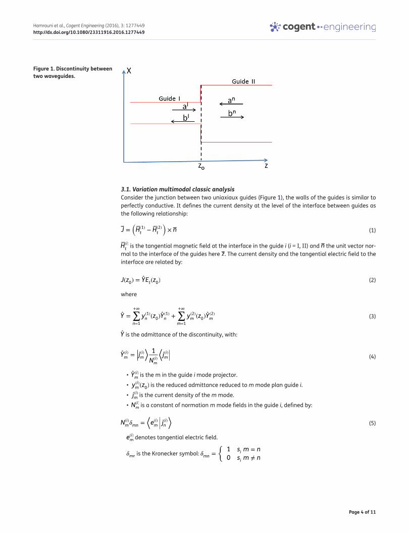
3.1. Variation multimodal classic analysisConsider the junction between two uniaxiaux guides (Figure 1), the walls of the guides is similar to perfectly conductive. It defines the current density at the level of the interface between guides as the following relationship:
�H(i)
t is the tangential magnetic field at the interface in the guide i (i = I, II) and �n the unit vector nor-
mal to the interface of the guides here �z. The current density and the tangential electric field to the interface are related by:
where
Y is the admittance of the discontinuity, with:
• Y (i)m is the m in the guide i mode projector.
• y(i)m (z0) is the reduced admittance reduced to m mode plan guide i.
• j(i)m is the current density of the m mode.
• N(i)m is a constant of normation m mode fields in the guide i, defined by:
e(i)m denotes tangential electric field.
�mn is the Kronecker symbol: �mn ={
1 si m = n
0 si m ≠ n
(1)�J =(�H(1)
t− �H(2)
t
)× �n
(2)J(z0) = YEt(z0)
(3)Y =
+∞∑n=1
y(1)n (z0)Y (1)
n +
+∞∑m=1
y(2)m (z0)Y (2)
m
(4)Y (i)m =
|||j(i)m
⟩1
N(i)m
⟨j(i)m|||
(5)N(i)m�mn =
⟨e(i)m j(i)n
⟩
Figure 1. Discontinuity between two waveguides.
Page 5 of 11
Hamrouni et al., Cogent Engineering (2016), 3: 1277449http://dx.doi.org/10.1080/23311916.2016.1277449
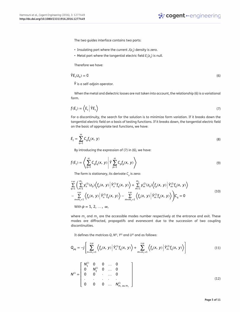
The two guides interface contains two parts:
• Insulating part where the current J(z0) density is zero.
• Metal part where the tangential electric field Et(z0) is null.
Therefore we have:
Y is a self-adjoin operator.
When the metal and dielectric losses are not taken into account, the relationship (6) is a variational form.
For a discontinuity, the search for the solution is to minimize form variation. If it breaks down the tangential electric field on a basis of testing functions. If it breaks down, the tangential electric field on the basic of appropriate test functions, we have:
By introducing the expression of (7) in (6), we have:
The form is stationary, its derivate Cp is zero:
With p = 1, 2, … , ∞,
where m1 and m2 are the accessible modes number respectively at the entrance and exit. These modes are diffracted, propagatifs and evanescent due to the succession of two coupling discontinuities.
It defines the matrices Q, N(i), Y(i) and U(i) and as follows:
(6)YEt(z0) = 0
(7)f (Et) =⟨Et YEt
⟩
(8)Et =
∞∑q=1
Cqfq(x, y)
(9)f (Et) =
⟨∞∑q=1
Cqfq(x, y) Y
∞∑p=1
Cpfp(x, y)
⟩
(10)
+∞∑q=1
�m1∑
n=1
y(1)n (z0)
�fp(x, y) Y
(1)
n fq(x, y)�+
m2∑
m=1
y(2)m (z0)
�fp(x, y) Y
(2)
m fq(x, y)�
−+∞∑
n=m1+1
�fp(x, y) Y
(1)
n fq(x, y)�−
+∞∑m=m
2+1
�fp(x, y) Y
(2)
m fq(x, y)��
Cq = 0
(11)Qpq = −j
[+∞∑
n=m1+1
⟨fp(x, y) Y
(1)
n fq(x, y)⟩+
+∞∑m=m
2+1
⟨fp(x, y) Y
(2)
m fq(x, y)⟩]
(12)N(i)
=
⎡⎢⎢⎢⎢⎢⎣
N(i)
10 0 … 0
0 N(i)
20 … 0
0 0 ⋅ … 0
⋅ ⋅ ⋅ ⋅ ⋅
0 0 0 … N(i)m1ou m
2
⎤⎥⎥⎥⎥⎥⎦
Page 6 of 11
Hamrouni et al., Cogent Engineering (2016), 3: 1277449http://dx.doi.org/10.1080/23311916.2016.1277449
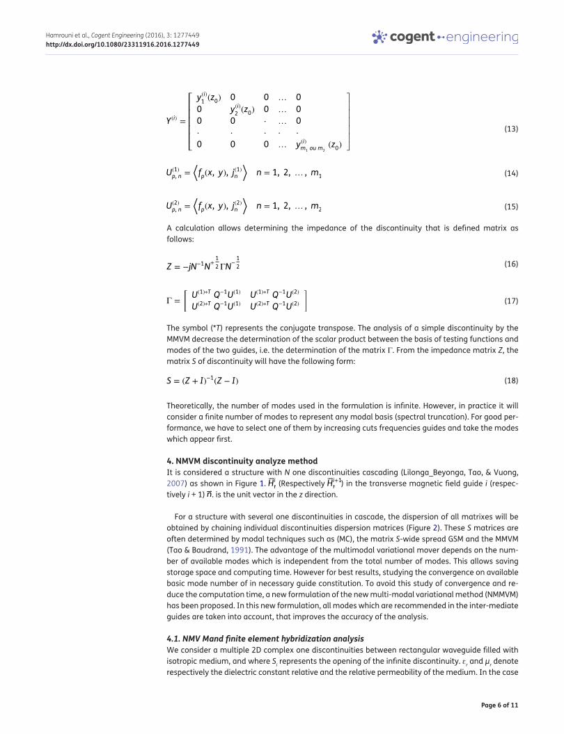
A calculation allows determining the impedance of the discontinuity that is defined matrix as follows:
The symbol (*T) represents the conjugate transpose. The analysis of a simple discontinuity by the MMVM decrease the determination of the scalar product between the basis of testing functions and modes of the two guides, i.e. the determination of the matrix Γ. From the impedance matrix Z, the matrix S of discontinuity will have the following form:
Theoretically, the number of modes used in the formulation is infinite. However, in practice it will consider a finite number of modes to represent any modal basis (spectral truncation). For good per-formance, we have to select one of them by increasing cuts frequencies guides and take the modes which appear first.
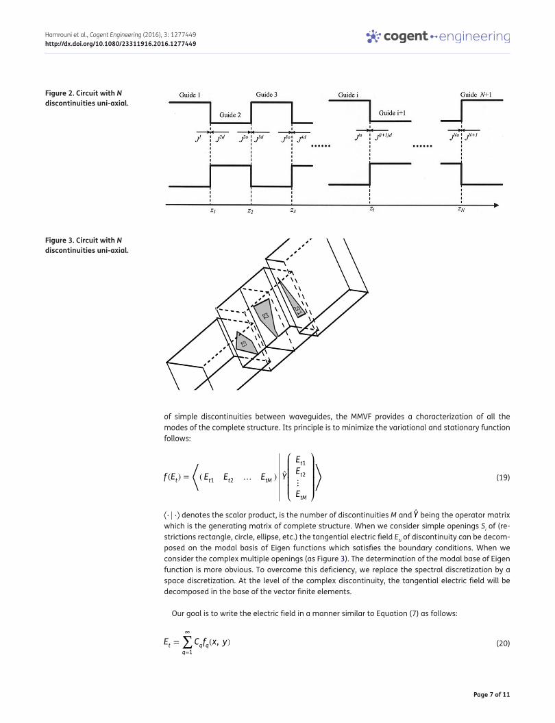
4. NMVM discontinuity analyze methodIt is considered a structure with N one discontinuities cascading (Lilonga_Beyonga, Tao, & Vuong, 2007) as shown in Figure 1. �Hit (Respectively �Hi+1t ) in the transverse magnetic field guide i (respec-tively i + 1) �n. is the unit vector in the z direction.
For a structure with several one discontinuities in cascade, the dispersion of all matrixes will be obtained by chaining individual discontinuities dispersion matrices (Figure 2). These S matrices are often determined by modal techniques such as (MC), the matrix S-wide spread GSM and the MMVM (Tao & Baudrand, 1991). The advantage of the multimodal variational mover depends on the num-ber of available modes which is independent from the total number of modes. This allows saving storage space and computing time. However for best results, studying the convergence on available basic mode number of in necessary guide constitution. To avoid this study of convergence and re-duce the computation time, a new formulation of the new multi-modal variational method (NMMVM) has been proposed. In this new formulation, all modes which are recommended in the inter-mediate guides are taken into account, that improves the accuracy of the analysis.
4.1. NMV Mand finite element hybridization analysisWe consider a multiple 2D complex one discontinuities between rectangular waveguide filled with isotropic medium, and where Si represents the opening of the infinite discontinuity. ɛr and μr denote respectively the dielectric constant relative and the relative permeability of the medium. In the case
(13)Y (i)
=
⎡⎢⎢⎢⎢⎢⎣
y(i)1(z0) 0 0 … 0
0 y(i)2(z0) 0 … 0
0 0 ⋅ … 0
⋅ ⋅ ⋅ ⋅ ⋅
0 0 0 … y(i)m1ou m
2
(z0)
⎤⎥⎥⎥⎥⎥⎦
(14)U(1)
p, n =
⟨fp(x, y), j
(1)
n
⟩n = 1, 2, … , m
1
(15)U(2)
p, n =
⟨fp(x, y), j
(2)
n
⟩n = 1, 2, … , m
2
(16)Z = −jN−1N+1
2 ΓN−1
2
(17)Γ =
[U(1)∗T Q−1U(1) U(1)∗T Q−1U(2)
U(2)∗T Q−1U(1) U(2)∗T Q−1U(2)
]
(18)S = (Z + I)−1(Z − I)
Page 7 of 11
Hamrouni et al., Cogent Engineering (2016), 3: 1277449http://dx.doi.org/10.1080/23311916.2016.1277449
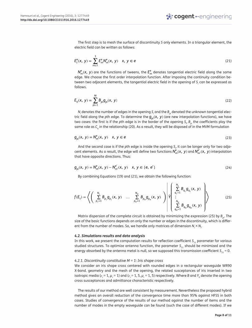
of simple discontinuities between waveguides, the MMVF provides a characterization of all the modes of the complete structure. Its principle is to minimize the variational and stationary function follows:
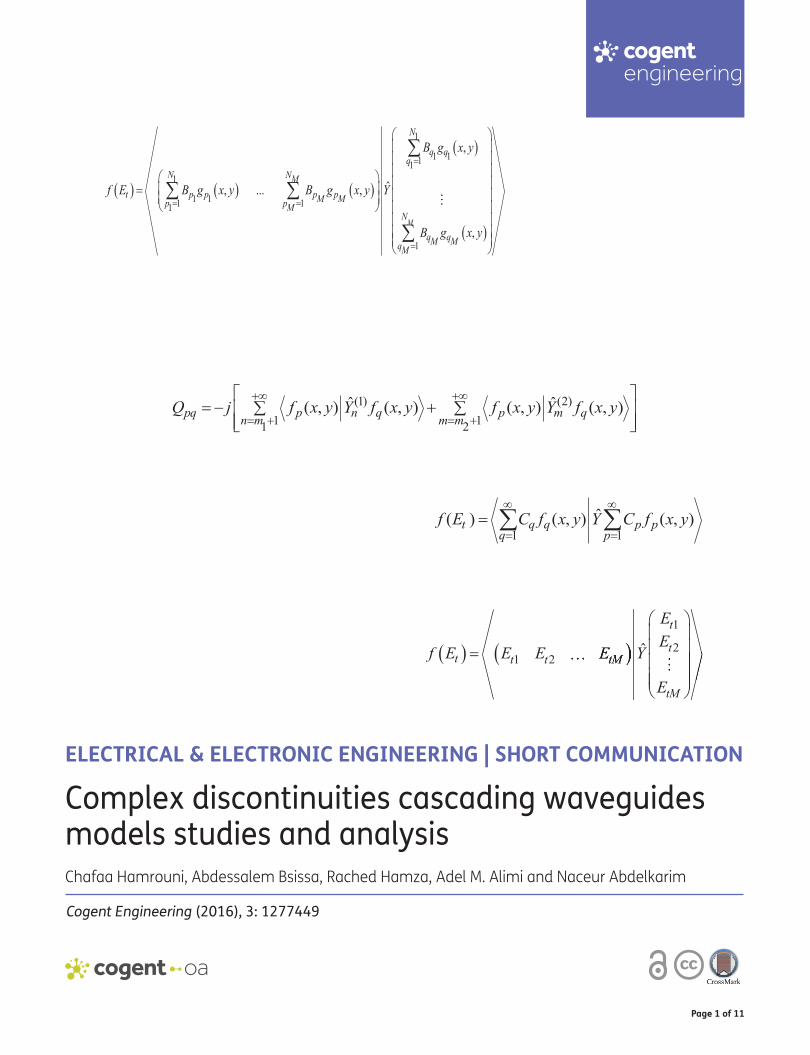
⟨⋅ ⋅⟩ denotes the scalar product, is the number of discontinuities M and Y being the operator matrix which is the generating matrix of complete structure. When we consider simple openings Si of (re-strictions rectangle, circle, ellipse, etc.) the tangential electric field Eti of discontinuity can be decom-posed on the modal basis of Eigen functions which satisfies the boundary conditions. When we consider the complex multiple openings (as Figure 3). The determination of the modal base of Eigen function is more obvious. To overcome this deficiency, we replace the spectral discretization by a space discretization. At the level of the complex discontinuity, the tangential electric field will be decomposed in the base of the vector finite elements.
Our goal is to write the electric field in a manner similar to Equation (7) as follows:
(19)f (Et) =
�( Et1 Et2 … EtM ) Y
⎛⎜⎜⎜⎜⎝
Et1Et2⋮
EtM
⎞⎟⎟⎟⎟⎠
�
(20)Et =
∞∑q=1
Cqfq(x, y)
Figure 2. Circuit with N discontinuities uni-axial.
Figure 3. Circuit with N discontinuities uni-axial.
Page 8 of 11
Hamrouni et al., Cogent Engineering (2016), 3: 1277449http://dx.doi.org/10.1080/23311916.2016.1277449
The first step is to mesh the surface of discontinuity S only elements. In a triangular element, the electric field can be written as follows:
Nem(x, y) are the functions of tweens, the Eem denotes tangential electric field along the same edge. We choose the first order interpolation function. After imposing the continuity condition be-tween two adjacent elements, the tangential electric field in the opening of Si can be expressed as follows.
Ni denotes the number of edges in the opening Si and the Bpi denoted the unknown tangential elec-tric field along the pth edge. To determine the gpi(x, y) (are new interpolation functions), we have two cases: the first is if the pth edge is in the border of the opening Si, Bpi the coefficients play the same role as Cq in the relationship (20). As a result, they will be disposed of in the MVM formulation
And the second case is if the pth edge is inside the opening Si, it can be longer only for two adja-cent elements. As a result, the edge will define two functions Nem(x, y) and Ne
�
m� (x, y) interpolation that have opposite directions. Thus:
By combining Equations (19) and (21), we obtain the following function:
Matrix dispersion of the complete circuit is obtained by minimizing the expression (25) by Bpi. The size of the basic functions depends on only the number or edges in the discontinuity, which is differ-ent from the number of modes. So, we handle only matrices of dimension Ni × Ni.
4.2. Simulations results and data analysisIn this work, we present the computation results for reflection coefficient S11 parameter for various studied structures. To optimize antenna function, the parameter S21 should be minimized and the energy absorbed by the antenna metal is null, so we supposed this transmission coefficient S21 = 0.
4.2.1. Discontinuity constitutive M = 1: Iris shape crossWe consider an iris shape cross centered with rounded edges in a rectangular waveguide WR90 X-band. geometry and the mesh of the opening, the related susceptances of iris inserted in two isotropic media (εr = 1, μr = 1) and (εr = 1, 5, μr = 1, 5) respectively. Where B and Y0 denote the opening cross susceptances and admittance characteristic respectively.
The results of our method are well consistent by measurement. Nevertheless the proposed hybrid method gives an overall reduction of the convergence time more than 95% against HFSS in both cases. Studies of convergence of the results of our method against the number of items and the number of modes in the empty waveguide can be found (such the case of different modes). If we
(21)Eet (x, y) =
3∑m=1
EemNem(x, y) x, y ∈ e
(22)Eti(x, y) =
Ni∑pi=1
Bpigpi(x, y)
(23)gpi(x, y) = Nem(x, y) x, y ∈ e
(24)gpi(x, y) = Nem(x, y) − N
e�
m� (x, y) x, y ∈ {e, e�}
(25)f (Et) =
��N1∑
p1=1
Bp1
gp1
(x, y) …
NM∑pM=1
BpMgpM
(x, y)
�Y
⎛⎜⎜⎜⎜⎜⎜⎝
N1∑
q1=1
Bq1
gq1
(x, y)
⋮
NM∑qM=1
BqMgqM
(x, y)
⎞⎟⎟⎟⎟⎟⎟⎠
�
Page 9 of 11
Hamrouni et al., Cogent Engineering (2016), 3: 1277449http://dx.doi.org/10.1080/23311916.2016.1277449
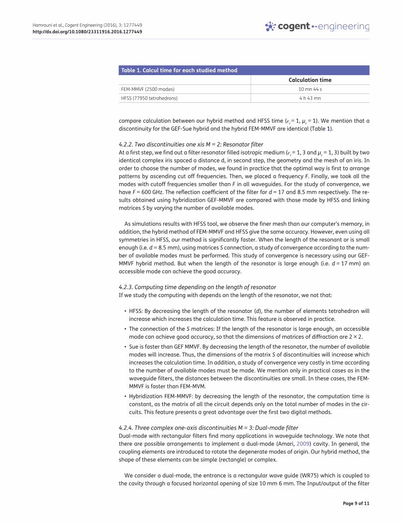
compare calculation between our hybrid method and HFSS time (εr = 1, μr = 1). We mention that a discontinuity for the GEF-Sue hybrid and the hybrid FEM-MMVF are identical (Table 1).
4.2.2. Two discontinuities one xis M = 2: Resonator filterAt a first step, we find out a filter resonator filled isotropic medium (εr = 1, 3 and μr = 1, 3) built by two identical complex iris spaced a distance d, in second step, the geometry and the mesh of an iris. In order to choose the number of modes, we found in practice that the optimal way is first to arrange patterns by ascending cut off frequencies. Then, we placed a frequency F. Finally, we took all the modes with cutoff frequencies smaller than F in all waveguides. For the study of convergence, we have F = 600 GHz. The reflection coefficient of the filter for d = 17 and 8.5 mm respectively. The re-sults obtained using hybridization GEF-MMVF are compared with those made by HFSS and linking matrices S by varying the number of available modes.
As simulations results with HFSS tool, we observe the finer mesh than our computer’s memory, in addition, the hybrid method of FEM-MMVF and HFSS give the same accuracy. However, even using all symmetries in HFSS, our method is significantly faster. When the length of the resonant or is small enough (i.e. d = 8.5 mm), using matrices S connection, a study of convergence according to the num-ber of available modes must be performed. This study of convergence is necessary using our GEF-MMVF hybrid method. But when the length of the resonator is large enough (i.e. d = 17 mm) an accessible mode can achieve the good accuracy.
4.2.3. Computing time depending on the length of resonatorIf we study the computing with depends on the length of the resonator, we not that:
• HFSS: By decreasing the length of the resonator (d), the number of elements tetrahedron will increase which increases the calculation time. This feature is observed in practice.
• The connection of the S matrices: If the length of the resonator is large enough, an accessible mode can achieve good accuracy, so that the dimensions of matrices of diffraction are 2 × 2.
• Sue is faster than GEF MMVF. By decreasing the length of the resonator, the number of available modes will increase. Thus, the dimensions of the matrix S of discontinuities will increase which increases the calculation time. In addition, a study of convergence very costly in time according to the number of available modes must be made. We mention only in practical cases as in the waveguide filters, the distances between the discontinuities are small. In these cases, the FEM-MMVF is faster than FEM-MVM.
• Hybridization FEM-MMVF: by decreasing the length of the resonator, the computation time is constant, as the matrix of all the circuit depends only on the total number of modes in the cir-cuits. This feature presents a great advantage over the first two digital methods.
4.2.4. Three complex one-axis discontinuities M = 3: Dual-mode filterDual-mode with rectangular filters find many applications in waveguide technology. We note that there are possible arrangements to implement a dual-mode (Amari, 2009) cavity. In general, the coupling elements are introduced to rotate the degenerate modes of origin. Our hybrid method, the shape of these elements can be simple (rectangle) or complex.
We consider a dual-mode, the entrance is a rectangular wave guide (WR75) which is coupled to the cavity through a focused horizontal opening of size 10 mm 6 mm. The Input/output of the filter
Table 1. Calcul time for each studied methodCalculation time
FEM-MMVF (2500 modes) 10 mn 44 s
HFSS (77950 tetrahedrons) 4 h 43 mn
Page 10 of 11
Hamrouni et al., Cogent Engineering (2016), 3: 1277449http://dx.doi.org/10.1080/23311916.2016.1277449
are the same, but turned off. π/2 The dual-mode cavity dimensions are 14.8 mm 14.8 mm 25 mm. Four 2D metals labs square size (3 mm 3 mm) and (1 mm 1 mm) are inserted into the corners of the square cavity. The position and shape of the four square metal slabs 2D were inspired by the refer-ence. Their sizes are chosen to improve the response of the filter. We recall that our hybrid method is versatile. It does depend on the form of discontinuities. A study of convergence, we considered all modes in the circuit of frequency below F = 250 GHz cuts
Using HFSS and hybrid FEM-MMVF, the reflection coefficient depends on the frequency. We consid-ered two isotropic media (ɛr = 1.2; μr = 1.2) and (ɛr = 1.1; μr = 1.1). The frequencies of resonance and Q-3 dB response the methods studied. We have obtained a good agreement with the results of HFSS that the EMF. Nevertheless, our hybrid method is significantly faster.
5. Discussion and conclusionIn this research was applied the method of S-parameter generalized analysis of multiple and single of one discontinuity in the metallic rectangular waveguides filled with meta materials isotropic. It introduces a hybrid tool for modeling of complex 2D in rectangular serial discontinuities waveguides. The study of the convergence based on available modes number is no longer necessary. Used simu-lation tool is applied to the modeling of large complex structures such multimode filters where its speed compared to commercial simulation tools was highlighted. The method of generalized S-parameters was applied and it was suggested a hybrid method that combines MVM and vector FEM and this for the analysis of one or more complex discontinuities in rectangular waveguides. The surface of discontinuity was divided into several rectangular (or triangular) elements where the tan-gential electric field is developed in a basic functions of the first order. This founding result is effec-tive and efficient, it presents an accurate results as a successful solution.
FundingThe authors would like to acknowledge the financial support of this work by grants from General Direction of Scientific Research (DGRST), Tunisia, under the ARUB program.
Author detailsChafaa Hamrouni1,4
E-mail: [email protected] Bsissa1
E-mail: [email protected] ID: http://orcid.org/0000-0001-9924-7131Rached Hamza2
E-mail: [email protected] M. Alimi3
E-mail: [email protected] Abdelkarim4
E-mail: [email protected] Institut Supérieure des Etudes Technologiques de Gabès—
ISET, Gabes, Tunisia.2 SUP’COM, University of Manar II, Tunis, Tunisia.3 REGIM Laboratory, The National School of Engineers of Sfax
(ENIS), University of Sfax, Sfax, Tunisia.4 The National School of Engineers of Gabes (ENIG), Research
Unit MACS (TN), University of Gabes, Gabes, Tunisia.
Citation informationCite this article as: Complex discontinuities cascading waveguides models studies and analysis, Chafaa Hamrouni, Abdessalem Bsissa, Rached Hamza, Adel M. Alimi & Naceur Abdelkarim, Cogent Engineering (2016), 3: 1277449.
Cover imageSource: Authors.
ReferencesAmari, S. (2009, February). Application of representation
theory to dual-mode microwave band pass filter. IEEE Transactions on Microwave Theory and Techniques, 57, 430–441. http://dx.doi.org/10.1109/TMTT.2008.2011194
Drabek, P., Peroutka, Z., Pittermann, M., & Cedl, M. (2011). New configuration of traction converter with medium-frequency transformer using matrix converters. IEEE Transactions on Industrial Electronics, 58, 5041–5048. doi:10.1109/TIE.2011.2138114
Green, J. J., & Sandy, F. (1974, June). Microwave characterization of partially magnetized ferrites. IEEE Transactions on Microwave Theory and Techniques, 22, 641–645. http://dx.doi.org/10.1109/TMTT.1974.1128306
Hasegawa, Y., Inoue, M., Hiraoka, T., & Hsu, J.-P. (2007). Equivalent network approach for field analysis of 3-D optical wave guide step discontinuity and their dynamic behavior. Microwave Conference, 2007, APMC 2007. Asia-Pacific, 1–4. doi:10.1109/APMC.2007.4554741
Jian Yi Zhou, S. S. A. (2004). A super absorbing boundary condition for the analysis of waveguide discontinuities with the finite-difference method. IEEE Microwave and Guided Wave Letters, 22, 1420–1425. doi:10.1109/JLT.2004.827671
Lilonga_Beyonga, D., Tao, J., & Vuong, T. H. (2007). Uniaxial discontinuities analysis by a new multimodal variational method-application to filter design. International Journal of RF and Microwave Computer-Aided Engineering, 17, 77–83. http://dx.doi.org/10.1002/(ISSN)1099-047X
Lindell, I. V., & Sihvola, A. H. (1994). Singularity of Green dyadic for bi-isotropic media. IET Journals & Magazines, 30, 842–843. doi:10.1049/el:19940622

Page 11 of 11
Hamrouni et al., Cogent Engineering (2016), 3: 1277449http://dx.doi.org/10.1080/23311916.2016.1277449
© 2017 The Author(s). This open access article is distributed under a Creative Commons Attribution (CC-BY) 4.0 license.You are free to: Share — copy and redistribute the material in any medium or format Adapt — remix, transform, and build upon the material for any purpose, even commercially.The licensor cannot revoke these freedoms as long as you follow the license terms.
Under the following terms:Attribution — You must give appropriate credit, provide a link to the license, and indicate if changes were made. You may do so in any reasonable manner, but not in any way that suggests the licensor endorses you or your use. No additional restrictions You may not apply legal terms or technological measures that legally restrict others from doing anything the license permits.
Cogent Engineering (ISSN: 2331-1916) is published by Cogent OA, part of Taylor & Francis Group. Publishing with Cogent OA ensures:• Immediate, universal access to your article on publication• High visibility and discoverability via the Cogent OA website as well as Taylor & Francis Online• Download and citation statistics for your article• Rapid online publication• Input from, and dialog with, expert editors and editorial boards• Retention of full copyright of your article• Guaranteed legacy preservation of your article• Discounts and waivers for authors in developing regionsSubmit your manuscript to a Cogent OA journal at www.CogentOA.com
Polder, D. (1949). On the theory of ferromagnetic resonance, Philosophers. Magazine, 40, 99–115.
Song, J., Ohnuki, S., Nyquist, D. P., Chen, Y. F., & Rothwell, E. J. (1994). Scattering of TE-polarized EM wave by discontinuity in grounded dielectric layer. IEEE Transactions on Microwave Theory and Techniques, 42, 481–488. doi:10.1109/22.277443
Song, Q. S., & Yin, G. (2007). Study of convergence rates of numerical methods for stochastic control problems. 2007 46th IEEE Conference on Decision and Control, 3108–3113. doi:10.1109/CDC.2007.4434198
Tao, J. W., & Baudrand, H. (1991). Multimodal variational analysis of uniaxial waveguide discontinuities. IEEE
Transactions on Microwave Theory and Techniques, 39, 506–516. http://dx.doi.org/10.1109/22.75293
Venugopalan, S., & Savvides, M. (2011). How to generate spoofed irises from an iris code template. IEEE Transactions on Information Forensics and Security, 6, 385–395. doi:10.1109/TIFS.2011.2108288
Zhang, G., & Liu, Y. (2000). Separation method of polarisation states. IEE Proceedings - Radar, Sonar and Navigation, 147, 75–79. doi:10.1049/ip-rsn:20000168
Zhou, J. Y., & Hong, W. (1997). A super absorbing boundary condition for the analysis of waveguide discontinuities with the finite-difference method. Microwave and Guided Wave Letters, IEEE, 7, 147–149, doi:10.1109/75.585194