IS 3829-1 (1999): Horizontal Cylindrical and Horizontal … · 2018-11-15 · is 3829 (part 1) :...
13
Disclosure to Promote the Right To Information Whereas the Parliament of India has set out to provide a practical regime of right to information for citizens to secure access to information under the control of public authorities, in order to promote transparency and accountability in the working of every public authority, and whereas the attached publication of the Bureau of Indian Standards is of particular interest to the public, particularly disadvantaged communities and those engaged in the pursuit of education and knowledge, the attached public safety standard is made available to promote the timely dissemination of this information in an accurate manner to the public. इंटरनेट मानक “!ान $ एक न’ भारत का +नम-ण” Satyanarayan Gangaram Pitroda “Invent a New India Using Knowledge” “प0रा1 को छोड न’ 5 तरफ” Jawaharlal Nehru “Step Out From the Old to the New” “जान1 का अ+धकार, जी1 का अ+धकार” Mazdoor Kisan Shakti Sangathan “The Right to Information, The Right to Live” “!ान एक ऐसा खजाना > जो कभी च0राया नहB जा सकता ह ै” Bhartṛhari—Nītiśatakam “Knowledge is such a treasure which cannot be stolen” IS 3829-1 (1999): Horizontal Cylindrical and Horizontal Rectangular Steam Sterilizers, Pressure Type (for Hospital and Pharmaceutical Use) [MHD 14: Hospital Planning]
Transcript of IS 3829-1 (1999): Horizontal Cylindrical and Horizontal … · 2018-11-15 · is 3829 (part 1) :...

Disclosure to Promote the Right To Information
Whereas the Parliament of India has set out to provide a practical regime of right to information for citizens to secure access to information under the control of public authorities, in order to promote transparency and accountability in the working of every public authority, and whereas the attached publication of the Bureau of Indian Standards is of particular interest to the public, particularly disadvantaged communities and those engaged in the pursuit of education and knowledge, the attached public safety standard is made available to promote the timely dissemination of this information in an accurate manner to the public.
इंटरनेट मानक
“!ान $ एक न' भारत का +नम-ण”Satyanarayan Gangaram Pitroda
“Invent a New India Using Knowledge”
“प0रा1 को छोड न' 5 तरफ”Jawaharlal Nehru
“Step Out From the Old to the New”
“जान1 का अ+धकार, जी1 का अ+धकार”Mazdoor Kisan Shakti Sangathan
“The Right to Information, The Right to Live”
“!ान एक ऐसा खजाना > जो कभी च0राया नहB जा सकता है”Bhartṛhari—Nītiśatakam
“Knowledge is such a treasure which cannot be stolen”
“Invent a New India Using Knowledge”
है”ह”ह
IS 3829-1 (1999): Horizontal Cylindrical and HorizontalRectangular Steam Sterilizers, Pressure Type (for Hospitaland Pharmaceutical Use) [MHD 14: Hospital Planning]


IS 3829 (Part 1) : 1999
Indian StandardSPECIFICATION FOR STEAM STERILIZERSPART 1 HORIZONTAL CYLINDRICAL AND HORIZONTAL RECTANGULAR
STEAM STERILIZERS, PRESSURE TYPE (FOR HOSPITAL AND PHARMACEUTICAL USE)
( Second Revision )
ICS 11.040.30
0 BIS 1999
B U R E A U O F I N D I A N S T A N D A R D SMANAK BHAVAN, 9 BAHADUR SHAH ZAFAR MARG
NEW DELHI 110002
April 1999 Price Group 4

Hospital Equipment Sectional Committee, MHD 14
FOREWORD
This Indian Standard (Part 1) (Second Revision) was adopted by the Bureau of Indian Standards, after the draftfinalized by the Hospital Equipment Sectional Committee had been approved by the Medical Equipment andHospital Planning Division Council.
This standard was first published in 1967 and was subsequently revised in 1978. The second revision of thisstandard is brought out keeping in view the latest developments in the manufacture of pressure type horizontalcylindrical and horizontal rectangular steam sterilizers (for hospital and pharmaceutical use). The revisedstandard incorporates reference to the latest Indian Standards for materials used for manufacture of doors,chambers of the sterilizers. This revision also takes into account the five amendments issued to this standardfrom time to time.
It is suggested that tap water, reasonably free from scale-forming constituents should be used for steam generation.If the water is hard it should be treated before it is used for steam raising [see IS 1680 : 1982 Code of practicefor treatment of water for low and medium pressure land boilers (third revision)].
The problem of explosion risk arising from fumes of anaesthetic agents have not been taken into considerationon the understanding, that all types of sterilizers dealt with in this standard would be installed generally rem~otefrom the anaesthetizing area in the operation theatre, and that the anaesthetic room would be outside the zoneof explosion risk. Installation of these sterilizers is not recommended in an operation theatre.
For the purpose of deciding whether a particular requirement of this standard is complied with, the final value,observed or calculated, expressing the result of a test or analysis, shall be rounded off in accordance withIS 2 : 1960 ‘Rules for rounding off numerical values (revised)‘. The number of significant places retained inthe rounded off value should-be the same as that of the specified value in this standard.

IS 3829 (Part 1) : 1999
Indian Standard
SPECIFICATION FOR STEAM STERILIZERSPART 1 HORIZONTAL CYLINDRICAL AND -HORIZONTAL RECTANGULAR
STEAM STERILIZERS, PRESSURE TYPE (FOR HOSPITAL AND PHARMACEUTICAL USE)
( Second Revision )1 SCOPE
This standard specifies requirements for non-automatic, automatic process control or pulsing typepressure steam sterilizers of horizontal cylindrical andhorizontal rectangular type designed for a workingpressure of 126 kN/m2 (1.26 kgf/cm2 approx) gaugebut shall be set to operate at 105 + 15 kNlm2 (1.05 -I-0.15 kgf/cm2 approx) gauge pressure (correspondingtemperature of the saturated steam inside the chamberabout 121°C).
2 REFERENCES
The Indian Standards given in Annex A containprovisions which, through reference in this text,constitute provision of this standard. At the time ofpublication, the editions indicated were valid. Allstandards are subject to revision, and parties toagreements based on this standard are ~encouragedto investigate the possibility of applying the mostrecent editions of the standards.
3 TERMINOLOGY
3.1 Sterilizer
For the purpose of this standard, the sterilizer shallmean a steam pressure appliance used for thedestruction of bacteria and related organisms.
4 DESIGN
4.1 The sterilizer shall consist of a chamber, with anannular steam jacket on the sides. The chamber shallshave a door at one end or both ends, as specified bythe purchaser.
4.2 The sterilizer shall be designed to operate on directsteam from a central source or by means of an attachedsteam generator (boiler) heated by electricity orkerosine stoves or gas or a combination of these(see 10.7), subject to the purchaser selecting one orthe oth.er of the heating arrangement.
4.3 The sterilizer shall be capable of performing thefollowing operations constituting one full cycle ofsterilization:
a) Generate steam and build up working pres-sure in the jacket, without admitting it to thechamber;
b) Admit steam to the chamber and allow it tobuild up to working pressure and tempera-ture (maintaining the pressure in the jacket)and retaining the working temperature for atleast 2 h;
c) Exhausting the chamber pressure, retainingthe jacket pressure; and
d) Drying of load in chamber (if required)through the circulation of dry, filteredair entering through a drying system asspecified in 8.i.5.
5 SHAPE AND SIZE
5.1 Shape
Sterilizers shall have a circular, square or rectangularcross section forming the main receptacle.
5.2 Size
The size of a sterilizer shall be determined by the sizeof the inside of the chamber, preferably conformingto Tables 1 and 2 read with Fig. 1 and 2. Other sizesof the sterilizers are also allowed as agreed betweenthe purchaser and the manufacturer provided theperformance tests and other requirements of thisstandard are fulfilled by the sterilizers.
NOTE - Sizes are determined by the size of the dressing drumsand the standard sizes of sheets rolled by steel mills.
6 MATERIAL
6.1 Various components of the sterilizers shall befabricated from combinations of materials given inAnnex B. The recommended uses of the sterilizersdepending on the combination of materials are alsogiven in Annex B. The sterilizers, in addition, shallsatisfy the requirements specified in -6.2 to 6.4.
-6.2 Where the sterilizer is designed specifically forbottled fluids, such as saline or other corrosivesolutions, the combinations of materials as shown atSl No. (i), (ii), (iii) in B-l under chamber and jacketshall be used. The purhcaser shall notify themanufacturer of particulars of such solutions at thetime of tendering.
6.3 When the seams and pipe connections are solderedor brazed it shall be done with oxy-acetylene, oxy-propane, air-acetylene or air-propane flame.
1

IS 3829 (Part 1) : 1999
6.4 In stainless steel sterilizers all joints shall bewelded by argon-arc process or with appropriate fluxcoated electrodes.
Table 1 Dimensions of Horizontal CylindricalSterilizers
(Clauses 5.2 and 10.4) .
Diameter (d) Length ( I )
(1) (2)mm mm400 600
400 1 100
500 900
so0 1 100
7.50 1 100
6.5 Piping
All piping shall be from non-corrosive materials like,stainless steel, brass, copper, etc. Brass or copperpiping shall be seamless or brazed as required by thepurchaser. Piping of stainless steel or clad materialmay have a welded seam.
Table 2 Dimensions of Horizontal Square orHorizontal Rectangular Sterilizers
(Clauses 5.2 and 10.4)
Width(w) Height (h)
(1) (2)mm mm600 600600 900900 1 050
1 050 1 200
Length ( 1)
(3)mm
1 200I 5002 1002 100
ENDRlNG
d O!A
All joints welded.
FIG. 1 STERILIZER , CYLI~~DERICAL
SEALING RlNG
S L O T T E D F O R L O C K I N G A R M S
All joints welded.
FIG. 2 STERILIZER , RECTANGULAR
2
7 CONSTRUCTION
7.1 The sterilizers shall consist of a chamber with asteam jacket. The chamber shall have door at one orboth ends, as specified by the purchaser. The joints inthe shell (chamber, jacket, back plate, if any, and endring) shall be fusion welded.
7.2 Shell
The general arrangement of the four items shall be asindicated in Fig. 1 and 2. The square or rectangularsterilizers shall have no end ring, but the jacket shallbe extended and slotted or flapped inwards at 90” toreceive the locking arms or members.
7.2.1 The number of sheets or plates required to formthe chamber and jacket shall not exceed two each incase of cylindrical sterilizer and four in case ofractangular sterilizer. All seams shall be butt fusionwelded (see IS 2825). When the shell is made frommore than one width of plate, the longitudinal seamsshall not fall in one line.
7.2.2 The,back plate shall always be formed out ofone sheet or plate.
7.2.3 In square or rectangular sterilizers there shallbe no joint at the longitudinal bend.
7.2.4 Stays
The stays reinforming the chamber and jacket in thecase square or rectangular sterilizers shall be of ‘T’section 50 mm x 50 mm x 5 mm. They shall be weldedalong the four sides of the shell, at a distance of notmore than 200 mm from each other and the sealingring and the back plate (see also Fig. 2). The lengthof the stay shall be about 75 percent of the side towhich it is welded, to allow space for steam circulation.The material of the stays shall be the same as that ofthe jacket.
7.2.4.1 The vertical section of ‘T’ shall be welded onboth sides, on to the chambers. The jacket sides shallbe slotted suitably at 200 mm distance, centre to centre,and the horizontal section of the ‘T’ shall be weldedto the jacket through these slots.
7.2.5 Corners shall be well rounded with a radius ofcurvature ranging between 90 and 140 mm dependingon the size and design. The radius of curvature of thecorners of the jacket shall be chosen to suit that of thechamber.
7.2.6 Each shell shall have at least the followingconnectors welded:
a) One for operating valve,
b) One for safety valve,
c) Two for steam inlet (in case the steam
3
440s)
7.2.6.1
IS 3829 (Part 1) : 1999
generator is attached to the sterilizer),
One for chamber drain,
One for steam inlet to chamber,
One for vacuum drier, and
One for validation for chamber.
The material of the connector shall be thesame as that of the member of shell to which it iswelded. When clad material is used for the chamber,the connector shall be of the same material as thecladding.
7.2.7 All outer surfaces of the jacket shall be suitablyinsulated (lagged), Further the insulation shall becovered suitably.
7.3 Door
The door shall be fitted on one side of the shell andopen sideways normally to the right side, facing thesterilizer unless otherwise specified by the purhcaser.In the case of double door sterilizers a door shall befitted to either end, The doors shall, in such case befitted to open on the right side at both ends, unlessotherwise specified by the purchaser. With doubledoor sterilizers there shall be no back plate, but anadditional end ring in the case of cylindricalsterilizers and extension and sealing of the jacket inthe case of square or rectangular sterilizers shall beprovided. The inside portion when made of mild steelsheet shall have a thin coating of zinc metal!izing(about 10 microns) or may be coated with heatresisting paint.
7.3.1 Locking Device
A door-locking device shall be so arranged that whenopening and closing the door, the locking arms ormembers are fully engaged before gasket seal can beestablished to ensure effective sealing. The door shalllock positively when pressure in the chamber is 35kNlm2 (0.35 kgf/cm2) gauge or more and the lock shallnot get released till the pressure falls below 35 kN/mZ(0.35 kgf/cm’) gauge. Provision shall be made totighten the door while in locked position. All squareor rectangular sterilizers shall have an additionalmanual lock.
7.3.2 Door Gasket
It shall be one piece without joint, moulded of steamresistant, resilient material. Neoprene EPDM orSilicon rubber or equivalent shall be used for thispurpose. It should be capable of effectively sealingthe door against internal pressure up to the hydrualictest pressure. The gasket material shall be durableenough to withstand the working temperature overlong periods.
IS 3829 (Part 1) : 1999
7.3.3 Adjustment
All doors shall have a device capable of adjustmentwhen misaligned.
8 FITTINGS
8.1 The following shall be provided on all sterilizers.
8.1.1 Operating I/alve
All sterilizers below size 600 mm x 900 mm x 1 500mm shall be provided with a multiport valve. Allsterilizers of size 600 mm x 900 mm x 1 500 mm,its equivalent or above, may have multiport valve orany other type of valve. However in both the casesfollowing cycle of sterilization shall be achieved:
a>
b)
c>
4
48.1.1.1
Preserving pressure in jacket without admit-ting it to chamber, till needed;Admitting steam to chamber, but maintain-ing the jacket pressure;
Exhausting the chamber of steam but main-taining jacket pressure;Circulating dry, filtered air for drying butmaintaining the jacket pressure; andExhausting the jacket of steam.
The operating valve shall be located in thefront part of the sterilizer and shall be easily accessible.
8.1.2 Exhaust Verne
There shall be two speeds for exhausting the chamber:
a) Up to 7 minutes, called ‘fast exhaust’ fordressing or unbottled loads; and
b) Over 7 up to 30 minutes, called ‘slow ex-haust’ for bottled loads or fluids.
8.1.3 Safety Valve
Where other means of controlling pressure are used,such as reducing valve for direct steam operation orpressure switch for electric operation or device for gasflame control, one spring loaded safety valve shall beprovided to the jacket.
8.1.3.1 Where the safety valve alsoacts as relief valveto regulate the operating presstire, an additional safetyvalve, either spring or weight loaded, shall beprovided. It shall be so constructed as to prevent anincrease in the steam pressure of more than 10 percentof the pressure at which the relief valve is set to liftand it shall shut down at a pressure not more than 10percent below the pressure at which the valve is set tolife.
8.1.4 Vacuum Breaker
The jacket shall be provided with an automatic deviceto admit air to jacket in the event of formation ofvacuum in the jacket due to steam condensation.
8.1.5 Drying System
The filter supplied with the drying system shall admitfiltered air to the chamber and shall entrain vapoursand odours to be conducted to exhaust. The filtersupplied shall be of the ceramic labyrinth type with amaximum pore size of 50 pm or a cast columncontaining at least 15 g of tightly packed nickel-copperalloy wool, and equipped with a condensate dripdevice.
8.1.6 Bane
For effective distribution of steam in the chamber abaffle of non-corrosive metal or a sprage pipe shall befitted to distribute steam effectively throughout thechamber.
8.1.7 Chamber Drain
The sterilizer chamber shall be fitted with one or morechamber drain lines, for thorough evacuation of airand condensate from the chamber, during the steamexposure stage of the sterilizing cycle. Each drainline shall be fitted with a thermostatic steam trap anda check valve. The bore shall be such as to allowevacuation within 10 to 15 minutes of introduction ofsteam, except for bulk sterilizers.
8.1.7.1 Plug screen
The chamber end of the drain line shall have an easilyremovable plug screen to prevent large particies fromentering the line.
8.1.7.2 Thermometer
The chamber drain line shall be fitted with atemperature measuring device which shall be mercurythermometer or dial type thermometer, before thecheck valve. The thermometer shall be readable fromthe front of the sterilizer. When a dial thermometeris provided the minimum diameter of the dial shall be60 mm with an accuracy of +1.5”C at any reading.
8.1.8 Gauges
All single door sterilizers shall he fitted with pressuregauge to indicate the jacket pressure and a compoundpressure-vacuum gauge to indicate the pressure in thechamber. Both gauges shall be easily readable fromthe front of the sterilizer.
8.1.8.1 In double-door sterilizers an additionalcompound gauge shail be fitted to the chamber, andshall be easily readable when facing the other doorfrom the other side of the sterilizer.
8.1.9 Automatic Process Control Unit and Recorder
If required by the purchaser, an automatic processcontrol unit with temperature and/or pressurerecorder may be provided to control the sterilization
cycle mentioned in 4.3 automatically with the optionto carry out ~the process of sterirization manually ifdesired.
Additionally a pulsing cycle may also be incorporatedto this process control to attain the following sequenceof stages.
Stage I - Air Removal - Sufficient air shall beremoved from the chamber after loading the sterilizerin one or more pressure/vacuum I;ulsing to permitproper steam penetration and quick attainment of thesterilization temperature.
Stage II - Sterilization - Steam shall be admitted toprovide sterilizing conditions within the chamber load.The sterilizing condition shall be such that when thechamber is loaded, the mean temperature of 121°C isattained and maintained with tolerance of +2”C inthe chamber for 15 min.
Provision may be made for alternate time temperaturerelationship in addition to the sterilizing conditionsspecified above.
Stage III - Drying - Steam shall be removed fromthe chamber and vacuum shall be held for a periodnormally not exceeding one hour.
Stage IV - Air Admission - Air shall be admittedinto the chamber through a micro filter ofapproximately 5 micron size.
8.1.9.1 The above sterilization cycle shall satisfy anappropriate heat sensitive type test.
8.1.10 Temperature Control and Measurement
Provision should be made to incorporate one or morethermocouples in different zones of the chamber ofthe sterilizer in order to control and measure thetemperature of the zone of the chamber.
9 HYDROSTATIC TEST
9.1 On completion of manufacture, the sterilizerchamber shall be subjected to a hydrostatic test of oneand a half times and the sterilizer jacket to twice theworking pressure.
9.1.1 The jacket shall be tested at atmospheric pressurein the chamber. The test pressure shall be maintainedfor not less than 20 min, during which time all theaccessible parts shall be examined. There shall be nosign of leakage, sweating, weakness or permanentdeformation.
9.2 The steam generating boiler shall be subjected tohydrostatic test of twice the working pressure of thesterilizer. Test pressure shall be maintained for notless than 20 min and during this time all the accessible
IS 3829 (Part 1) : 1999
parts shall beexamined. There shall be no sign ofleakage, sweating, temporary or permanentdeformation.
10 METHODS OFSTERILIZERS
10.1 Source of Supply
Steam shall be supplied
STEAM SUPPLY TO
to sterilizers either directlyfrom a steam boiler of the establishment or from abuilt-in steam generator, as specified by thepurchaser. In the latter case, the steam generatormay be heated either electrically or by kerosine stovesor by gas. Ractangular sterilizers of sizes 900 mm x1050 mm x 2 100 mm and 1 050 mm x 1 200 mmx 2 100 mm, shall be available for direct steamoperation only.
10.2 Direct Steam Operation
When steam is supplied directly from a steam boilerof the establishment, the steam shall first enter thesteam jacket through a suitable steam-strainerpressure-reducing valve. The reducing valve shallbe adjusted for an inlet gauge pressure of minimum280 (2.8 cm2 approx) and outlet gauge pressure of105 to 120 kN/m2 (1.05 to 1.2 kgf/cm* approx). Astop valve, to shut off steam supply to jacket shall beprovided.
10.2.1 The jacket shall have one or more steam trapsat the bottom to drain the condensate.
10.3 Built-in Steam Generator
This steam generator shall be attached to the undersideof the shell, with two steam inlet pipes to the jacket.These inlet pipes may also act as supports for the steamgenerator. It shall be easily disconnected for cleaning.It shall be cylindrical in construction and all jointsshall be butt fusion welded in accordance with bestpractice of welding for pressure vessels.
10.3.1 All steam generators shall be provided witha gauge glass of wall thickness at least 1 mm toindicate water level and self-locking gauge glassvalves.
10.4 Electric Heating
Where the steam generator is electrically heated, itshall be by immersion heaters, wired for operationon 3-phase 4 wire, 4001440 V, 50 Hz ac supply orany other supply, if specifically required by thepurchaser. The electric load for various sizes ofsterilizers given in Tables 1 and 2 shall be asfollows:
5
IS 3829 (Part 1) : 1999
a) For Horizontal Cylindrical Sterilizers
Sizes Load
Z-Y&ZkW
mm mm400 600 6400 1 100 9500 900 9500 1 100 9750 1 100 18
b) For Horizontal-Square or HorizontalRectangular Sterilizers
Sizes Load
/ kWWidth Height Length
mm mm mm
600 600 1 200 18
600 900 1 500 36
The heaters shall be easily accessible. A switch shallbe provided on the control panel to isolate the heaterfrom the mains.
10.4.1 Low Water Protection
In case of electrically heated boilers, a low waterprotection for heaters shall be provided, to cut offelectric supply to heaters through a contactor if thewater level runs below the heater level.
10.4.2 Pressure Control
Working pressure, in the case of electrically heatedsterilizers. should preferably be controlled through apressure switch connected preferably to the steamgenerator or to the jacket but not to the chamber.
10.4.3 Switch Box
The contactor, switches and pilot lights shall be locatedin one box, mounted on the stand of the sterilizer.
10.5 Stove Heating
The steam generator specified in 10.3, shall havesuitable kerosine burners underneath. The burnersshall be kerosine fired through a pressure-kerosinetank.
10.5.1 The steam generator shall have suitablearrangements for protection against open flame.
10;6 Gas Heating
The steam generator shall be the same as for stoveheating as in 10.5 but instead of kerosine burnerssuitable gas burners shall be provided.
10.7 Combination Heating
Sterilizers, when so specified, shall be supplied for
any of the following combination heating, operatingindependently:
Direct steam/electric
Direct stearn/keorsine stoveDirect steam/gas
Electric/kerosine stoveElectric/gas
In the last two cases, the electric wiring shall besuitably protected against heat from the burner flame.
10.8 Capacity
The capacity of the steam generator in any size of thesterilizer shall be sufficient to give two complete cyclesof sterilization.
11 ACCESSORIES
11.1 When specified by the purchaser, the followingaccessories shall be provided.
11.1.1 Loading Carriage and Trolley
The carriage shall be suitable for loading the particulartype or types of loads specified by the purchaser. Thecarriage shall roll on rails, fixed to the chamber. Inthe case of stainless steel chamber, the rails shall alsobe stainless steel.
11.1.1.1 The carriage shall roll in and roll out freelyon a trolley mounted on robust wheels or castros ordrop rails. The trolley shall have provision for lockingthe carriage and shall have arrangement to lock itselfon the steriiizer during loading and unloading.
11.1.1.2 In case of stainless steel chamber the materialof the carriage shall be the same as the material of thechamber. For mild steel sterilizers the carriage shallpreferably be of stainless steel.
11.1.2 Trays or Racks
Trays or racks shall be provided in the chamber of thesize, shape and material as agreed to between thepruchaser and the manufacturer.
11.1.2.1 In case of racks for instruments, the rackshall contain a number of removable trays made ofstainless steel.
11.1.3 Thermograph
All sterilizers shall have arrangement in the chamberdrain line to fit a thermograph at any time. Thethermograph when supplied may be operatedelectrically or by spring motor (mechanical).
11.1.3.1 The thermograph chart shall be graduatedon the Celsius scale. The thermograph shall recordtemperature over a period of 24 h. Lock and keyarrangement shall be provided on the door of thethermograph.
6
11.1.4 Flush Mounting
Sterilizers shall be arranged for installation througha wall to expose the door and the-necessary operatinghandles and instruments on one side. The rest of thesterilizer shall lie on the other side.
11.1.4.1 The sterilizer shall be provided with a panelas specified by the purchaser to be mounted in thefront, flush with the wall.
11.1.4.2 All extended valve spindles shall besupported through metallic sleeves.
12 MARKING
12.1 Each sterilizer shall be legibly and indeliblymarked with the following:
a!b)C)4e)
Identification of the manufacturer;Code and serial number;Working pressure;Hydrostatic test pressure; andWattage, voltage, phase and cycle in the caseof electrically operated steam generators.
12.2 BIS Certification Marking
The sterilizer may also be marked with the StandardMark.
IS No.
306 : 1983
318 : 1981
1364
(Part 1) : 1992
(Part 2) : 1992
(Part 3j : 1992
(Part 4) : 1992
IS 3829 (Part 1) : 1999
12.2.1 The use of the Standard Mark is governed bythe provisions of Bureau of Indian Standards Act 1986,and the Rules and Regulations made thereunder. Thedetails of conditions under which the licence for theuse of Standard Mark may be granted to manufacturersor producers, may be obtained from the Bureau ofIndian Standards.
13 OPERATED MANUAL
Each sterilizer shall be accompanied by an operatingmanual which shall contain the followinginformation:
a)
b)c>4
4
Instructions and plan for installation of thesterilizer,
Operation of the sterilizer,
Routine maintenance and service,
Steam penetration time for various packaged .loads, and
Materials used or combination of materialsused for chamber and jacket.
14 PACKING
Each sterilizer shall be packed as agreed to betweenthe manufacturer and the supplier.
ANNEXA(Clause 2.1)
LIST OF REFERRED INDIAN STANDARDS
Title
Tin bronze ingots and castings(third revision)
Leaded tin bronze ingots and cast-ings (second revision)
Hexagoh head bolts, screws andnuts product grades A and BHexagon head bolts (size rangeMl .6 to M64) (third revision)
Hexagon head screws (size rangeMl .6 to M64) (third revision)
Hexagon nuts (size range Ml .6 toM64) (third revision)
Hexagon thin nuts (chamfered)(size range Ml.6 to M64) (thirdrevision)
IS No.
(Part 5) : 1992
2002 : 1992
2041 : -1995
2825 : 1969
6911 : 1992
Title
Hexagon thin nuts (unchamfcred)(size range M 1.6 LO M63) (thirdrevision)
Steel plates for pressure vessels forintermediate and high temperatureservice including boilers (securrdrevision)
Steel plates for prc.isure vesselsused at moderate and low tempera-ture (second t-evision)
Code for unfired pressure vessels
Stainless steel plate, sheet and strip(first rwisiwz)
IS 3829 (Part 1) : 1999
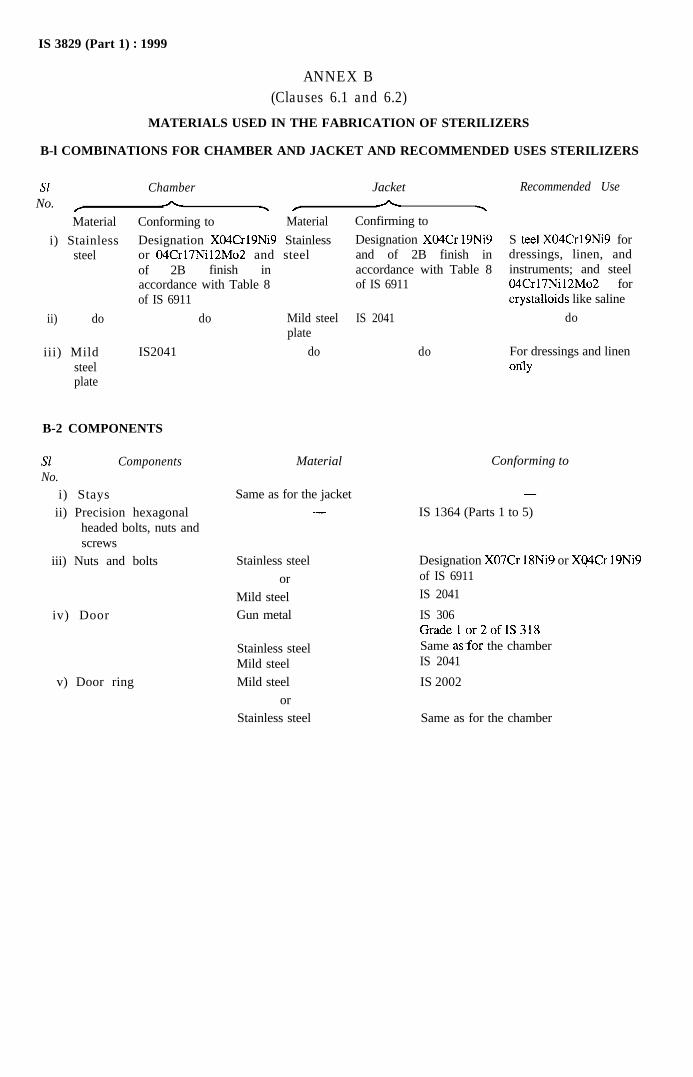
ANNEX B(Clauses 6.1 and 6.2)
MATERIALS USED IN THE FABRICATION OF STERILIZERS
B-l COMBINATIONS FOR CHAMBER AND JACKET AND RECOMMENDED USES STERILIZERS
SlNo. f
Chambern
Jacket
- / n YMaterial
i) Stainlesssteel
Conforming to Material
Designation XO4Cr19Ni9 Stainlessor 04Cr17Ni12Mo2 and steelof 2B finish inaccordance with Table 8
Confirming to
Designation XO4Cr 19Ni9and of 2B finish inaccordance with Table 8of IS 6911
ii) do
iii) Mildsteelplate
of IS 6911
do
IS2041
B-2 COMPONENTS
Sl ComponentsNo.
i) Staysii) Precision hexagonal
headed bolts, nuts andscrews
iii) Nuts and bolts
iv) Door
v) Door ring
Mild steel IS 2041plate
do
Material Conforming to
Same as for the jacket-
Stainless steelor
Mild steelGun metal
Stainless steelMild steelMild steel
orStainless steel
do
Recommended Use
S tee1 X04Crl9Ni9 fordressings, linen, andinstruments; and steel04Crl7Ni12Mo2 forcrystalloids like saline
do
For dressings and linenonly
-
IS 1364 (Parts 1 to 5)
Designation X07Cr 18Ni9 or Xq4Cr 19Ni9of IS 6911IS 2041
IS 306Gradelor2ofIS318Same asfor the chamberIS 2041
IS 2002
Same as for the chamber