IS 2720-part28
23
IS : 2729 ( Part XXVIII ) - 1974 ( Roeffimod 1995 ) Indian Standard METHODS OF TEST FOR SOILS PART XXVIII DETERMINATION OF DRY DENSITY OF SOILS IN-PLACE, BY THE SAND REPLACEMENT METHOD ( First Revision ) Sixth Reprint AUGUST 1998 UDC 624.131.431.5 0 CopVright 1974 Gr 6 BUREAU OF INDIAN STANDARDS MANAK BHAVAN, 9 BAHADUR SHAH ZAFAR WARG NEW DELHI 110002 October 1974
description
soil code
Transcript of IS 2720-part28
IS : 2729 ( Part XXVIII ) - 1974 ( Roeffimod 1995 )
Indian Standard METHODS OF TEST FOR SOILS
PART XXVIII DETERMINATION OF DRY DENSITY OF SOILS IN-PLACE, BY THE SAND
REPLACEMENT METHOD
( First Revision )
Sixth Reprint AUGUST 1998
UDC 624.131.431.5
0 CopVright 1974
Gr 6
BUREAU OF INDIAN STANDARDS MANAK BHAVAN, 9 BAHADUR SHAH ZAFAR WARG
NEW DELHI 110002
October 1974
IS : 2720 ( Part XXVIII ) - 1974
Indian Standard METHODS OF TEST FOR SOILS
PART XXVIII DETERMINATION OF DRY DENSITY OF SOILS IN-PLACE, BY THE SAND
REPLACEMENT METHOD
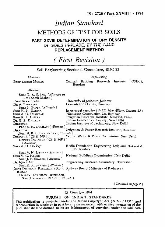
( First Revision ) Soil Engineering Sectional Committee, BDC 23
Chairman
PROF DINESH MOHAN
Re@esenting
Central Building Research Institute ( CSIR ), Roorkee
Members
SHKI G. R. S. JAIN (Alternate to Prof Dinesh Mohan )
PROP ALAM SINCH Universiky of Jodhpur, Jodhpur DR A. BANER~EE Cementation Co Ltd, Bombay
SHRI S. &PTA (Alternate ) SHRI K. N. DADIT;A In personal capacity ( P-820 New Al&we, Cnlcutta 53) SHRI A. G. DASTIDAR Hindustan Construction Co, Bombay SHRI R. L. DEWAN Irrigation Research Institute, Khagaul. Patna FziT:RD~~~~~~ Indian Geotechnical Society, New Delhi
Indian Institute of Technology, New Delhi PROF S. K. GULHATI ( Alternate )
DIRECTOR Irrigation 8r Power Research Institute, Amritsar &WI B. B. L. BHATNAGAR ( Alternate )
I)IRECTOR(CS & MRS) Central U’ater & Power Commission, New Delhi DEPUTY DIRECTOR ( CS & MRS )
(Alternate ) SHRI A. H. DIVANJI Rodio Foundation Engineering Ltd; and Hazarat &
Co, Bombay SHRI A. N. JANGLE ( Alternate )
SJlRl v. G. HEGDE National Buildings Organization, New Delhi SHRI J. P. SHARMA ( Alternate )
DR IQBAL ALI Engineering Research Laboratory, Hyderabad SHRI K. R. SAXENA (Alternate )
JOINT DIRECTOR RESEARCH ( FE ), Railway Board ( Ministry of Railways ) RDSO DEPUTY DIRECTOR RESEARCH, SOIL MECHANICS, RDSO (dlternafe)
( Continued on page 2 )
@ Copyright 1974
BUREAU OF INDIAN STANDARDS This publication is protected under the Indian Copyrighr Act (XIV of 1957 ) and reproduction in whole or in part by any means except with written permission of the publisher shall be deemed to be an infringement of copyright under the said Act.
;”
I

M#UlbWS Rcprarmfing SHRI 0. P. MALXOTRA Public Works Dcpartmcnt, Govcrnm cnt of Punjab Smu J. S. MAYA
SRRI A. S. Banmor ( AZrsnrote ) Roada Wing ( Ministry of Shipping & T-port)
Sanr M. A. MEHTls Concrete Association of India, Bombay Smu T. M. biRNON (Al&ma&)
Smu T. K. NATA~AJAN Central Road Research Institute ( CSIR ), New Delhi RFdEARcst OFFmEa Building & Roada Rcacarch Laboratory, Public
Worka Department, Government of Punjab MAJK.M.S.SAHAQ Engineer-in-Cbief’a Branch, Army Headquartem
ssrm P. PuYHmoAMANr ( AI&auti ) fbRRTARY ckntrd Board of Irrigation & Power, New D&i
I.br~wr~ SBCRETAIlY (Altemate) DRSHAyQIERPRAKXjH University of Roorkee, Roorkee Srmt H. D. Sa= Irrigation Researc h Institute, Roorkee Sup~anrrw~~~o ENOINIXER (PLAN- Concrete & Soil Rmearcb Laboratory, Public Worka
NINO & Dsk?tGN tiCLE) Department, Government of Tamil Nadu Exnmvn ENOINEER ( INCHAROE
SOIL MEcnANlcn & RmEAacn DIMnON ) ( &tt’?IU~ )
&mI~ g $W~Al=stAN Institution of Engineera ( India ), Calcutta . . All India Instrument Manufacturers ik Deakn
Association, Bombay Smu V. K. V~EV~ ( Alternate )
SHRI H. G. V- Publi0yv’ks Department, Gov emment of Uttar
Srmr D. C. Csixruavam ( Altemutc ) Smu D. AJIT%~ Sm
Director ( Civ Engg ) Director CIeral, BIS,( Ex-@& M&)
Stcr&tp
SIiltIG.ti
Deputy Director ( Civ Engg ), BIS
Soil Testing Procedures and Equipment Subcommittee, BDC 23 : 3
PROF hAM SINOH University of Jodhpur, Jodhpur
Members SHRI. N. K. BERRY
SHRI N. K. Am+ ( A~tenafe ) DR R. K. BHANDARI SHIU T. N. BHAROAWA
SHRI A. S. BI~HNOI ( Alternate ) DR A. K. CW~TERJEE
Beas Dams Project, Talwara Township
Central Road Research Institute ( CSIR), New Delhi Roads Wing ( Ministry of Shipping & Transport )
Publzraysks Department, Government of Uttar
DR B. L. DHAWAN ( Alkmute ) -_- Irrigation Research Institute, Kbagaul, Patna Central Water & Power Co mmission, New Delhi
S)
SHRI K. L. IJEWAN DIRECTOR ( CS & MRS )
ti[A~~;~cTOR ( CS & MR c
2

IS : 2720 i Part XXVIII ) - 1974
Indian Standard METHODS OF TEST FOR SOILS
PART XXVIII DETERMINATION OF DRY DENSITY OF SOILS IN-PLACE, BY THE SAND
REPLACEMENT METHOD
( First Revision )
0. FOREWORD
0.1 This Indian Standard ( Part XXVIII ) ( First Revision ) was adopted by the Indian Standards Institution on 21 February 1974, after the draft finalized by the Soil Engineering Sectional Committee had been approved by the Civil Engineering Division Council.
0.2 With a view to establish uniform procedures for the determination of different characteristics of soils and also for facilitating comparative studies of the results, the Indian Standards Institution is bringing out this Indian Standard methods of test for soils ( IS : 2720) which will be published in parts. This part [ IS ; 2720 (Part XXVIII ) ] deals with the determination of dry density of soil, in-place, by the sand replacement method. The in-place density of natural soil is needed for the determination of bearing capacity of soils, for the purpose of stability analysis of natural slopes, for the determination of pressures on underlying strata for calculation of settle- ment, etc. In compacted soils the in-place density ‘is needed to check the amount of compaction that the soil has undergone for comparison with design data. The correct estimation of the in-place density of both natural and compacted soils is therefore of imptrtance.
0.2.1 This standard was originally published in 1966. In this revision the sieve size for defining fine-grained soils has been changed to 2 mm. An appendix has been added for the determination of water content and dry density of medium- and coarse-grained soils containing appreciable gravel fraction.
0.3 This standard is divided into two sections. Section 1 prescribes the method suitable for fine- and medium-grained soils using the small sand pouring cylinder; Section 2 lays down the method which uses the large sand pouring cylinder and is suitable for fine-, medium- and coarse-grained soils containing stones which make the test of Section 1 difficult to perform.
3
IS : 2720 ( Part XXVIII) - 1974
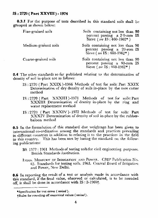
0.3.1 For the purpose of tests described in this standard soils shall grouped as shown below:
Fine-grained soils Soils containing not less than percent passing a 2.0-mm Sieve ( see IS : 460-1962* )
Medium-grained soils Soils containing not less than percent passmg a ZO-mm Sieve ( see IS : 460-1962* )
Coarse-grained soils Soils containing not less than percent passing a 40-mm Sieve ( see IS : 460-1962* )
be
90 IS
90 IS
90 IS
0.4 The other standards so far published relating to the determination of density of soil in-place are as follows:
IS : 2720 (Part XXIX )-1966 Methods of test for soils: Part XXIX Determination of dry density of soils in-place by the core cutter method
IS : 2720 ( Part XXX111 )-1971 Methods of test for soils: Part XXX111 Determination of density in-place by the ring and water replacement method
IS : 2720 ( Part XXXIV)- 1972 Methods of test for soils: Part XXXIV Determination of density of soil in-place by the rubber- baloon method
0.5 In the formulation of this standard due weightage has been given to international co-ordination among the standards and practices prevailing in different countries in addition to relating it to the practices in the field in this country. This has been met by basing the standard on the follow- ing publications:
BS 1377 : 1961 Methods of testing soils for civil engineering purposes. British Standards Institution.
INDIA. MINISTRY OF IRRIGATION AND POWER. CBIP Publication PJo. 42. Standards for testing soils. 1963. Central Board of Irrigation and Power, New Delhi.
0.6 In reporting the result of a test or analysis made in accordance with this standard, if the final value, observed or calculated, is to be rounded off, it shall be done in accordance with IS : 2-1960t.
*Specification for test sieves ( rerked ). t~ula for rounding off numerical values ( rruisrd ).
4

IS : 2729 ( Part XXVIII ) - 1974
SECTION I METHOD SUITABLE FOR FINE- AND MEDIUM- GRAINED SOILS : SMALL POURING CYLINDER METHOD
1. SCOPE
1.1 This method covers the determination, in-place, of the dry density ( in g/cm3 or kg/m3 ) of natural or compacted fine- and medium-grained soils for which a small sand-pouring cylinder is used. The method is applicable to layers not exceeding 150 mm in thickness ( see Note ).
NOTE -With granular materials having little or no cohesion, particularly when they are wet, there is a danger of errors in the measurement of dry density by thii method. These errors are caused by the slumping of the sides of the excavated density hole and always result in an over-estimation of the density.
2. APPARATUS
2.1 Small Sand-Pouring Cylinder - similar in essential details to that shown in Fig. 1.
2.2 Tools for Excavating Holes -suitable tools, such as a scraper tool similar to that shown in Fig. 2 to make a level surface; bent spoon, dibber shown in Fig. 3.
2.3 Cylindrical Calibrating Container-with an internal diameter of 100 mm and an internal depth of 150 mm (see Note 1 under 4.2.2 ) of the type illustrated in Fig. 4 fitted with a flange approximately 50 mm wide and about 5 mm thick surrounding the open end. The volume of the container should be given to an accuracy of 0.25 percent.
2.4 Balance - accurate to 1 g.
2.5 Plane Surface: Glass or Perspex Plate or Other Plane Surface - about 450 mm square and 9 mm thick or larger.
2.6 Metal Containers -to collect excavated soil. A convenient size is one about 150 mm diameter and 200 mm deep with a removable cover.
2.7 Cylindrical Steel Core-Cutter - of steel, 127.4 f 0.1 mm long and 100 mm f 0.1 mm internal diameter with a wall thickness of 3 mm bevelled at one end. One suitable type is illustrated in Fig. 5. The cutter shall be kept adequately greased.
2.8 Metal Tray with Hole - 300 mm square and 40 mm deep with a 100 mm hole in the centre.
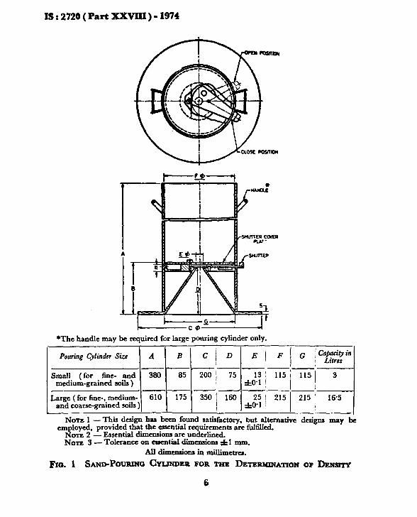
IS : 2720 ( Part XXVIII ) - 1974
*The handle be required for large pouring cylinder only.
Large (for fine-, mcdium- and coarse-gained soils)\ ‘lo 1 175 1 350 1 160 ] -J$ / *15 1 ‘15 ! le5
NOTL 1 - Thjs design has been found fatisfactory, but alternative designs may de ernJtlo$ provldcc! that the -~a rqmrements are fult’ikd.
- Essential duncnslons are underlined. NOTE 3 - Tolerance on essential dimensions f 1 mm.
Ail dimcnnions in millimetrcS.
Fm. 1 SANDPOURPIO CYLINDER FOR THE DETERMINATION OF DENSITY
6

xs:2720(PRrtxxvm)-1974
WOODEN HANDLE \
NOTE -This design has been found satisfactory, but alternative de&e may be employed.
All diicnaion3 in millimetru.
FICA 2 SCRAPER FOR LEVELLINO SURFACZ OF SOIL
NOTE - ‘IIds design has bccu found aatiskctory, but altcmative dcsigw may he employed.
All dim&ona in millimetred.
FIG. 3 DBBER FOR Dxoonm DENSITY How
7
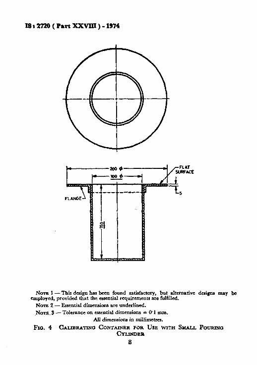
Is12720(PartxxvIII)-1974
1 r 7 FLANGE
Nom 1 -This design has bun found satisfactory, but alternative designs may be employed, provided that thq essential requirements are fulfilled.
NOTEZ- Essential dimensions arc underlined.
_ND~ 3 -Tolerance on essential dimensions * 0.1 mm.
All dimensions in millimctrcs.
FIG. 4 CALIBRATINO CONTAINER FOR USE WITH SMALL POURIW CYLINDER
8
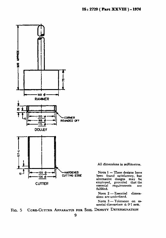
IS : 2720 ( Part XXVIIl ) - 1974
Luo 9-d RAMMER
CUTTER
All dimensions in millimetrcs.
NOTE 1 - Thue designs have been found satisfactory, but alternative designs may be employed, provided that the essential requirements are fulfilled.
NOTE 2 - Essential dimen- sions are underlined.
NOTE 3 -Tolerance on es- sential dimensions f 0.1 mm.
Fra. 5 CORE-CUTTER APPARATUS FOR SOIL DENSITY DETERMINATION 9

IJ t 2720 ( Part XXVIII ) - 1374
3. MATERIAL ( SAND )
3.1 Clean, uniformly graded natural sand passing the l’OO-mm IS Sieve and retained on the 600-micron IS Sieve shall be used. It shall be free from organic matter, and shall have been oven dried and stored for a suitable period to allow its water content to reach equilibrium with atmos- pheric humidity ( see Note ).
NOTE - Generally a storage period, after oven drying, of about 7 days is sufficient for the water content of the sand to reach equilibrium with the atmospheric humidity. The sand should not be stored in air-tight containers and should be thoroughly mixed before use. If sand is salvaged from holes in compacted soils after carrying out the test, it is advisable to sieve, dry and store this sand again before it is used in further sand replacement tests.
4. PROCEDURE
4.1 Calibration of Apparatus
4.1.1 The method given in 4.1.1.1 to 4.1.1.4 shall be followed for the determination of the weight of sand in the cone of the pouring cylinder.
4.1.1.1 The pouring cylinder shall be filled so that the level of the sand in the cylinder is within about 10 mm of the top. Its total initial weight ( W, ) shall be found and shall be maintained constant throughout the tests for which the calibration is used. A volume of sand equivalent to that of the excavated hole in the soil ( or equal to that of the calibrat- ing container ) ( fee Note 1 under 4.2.2 ) shall be allowed to run out of the cylinder under gravity. The shutter on the pouring cylinder shall then be closed and the cylinder placed on a plane surface, such as a glass plate.
4.1.1.2 The shutter on the pouring cylinder shall be opened and sand allowed to run out. When no further movement of sand takes place in the cylinder the shutter shall be closed and the cylinder removed carefully.
4.1.1.3 The sand that has filled the cone of the pouring cylinder (that is,’ the sand that is left on the plane surface ) shall be collected and weighed to the nearest gram.
4.1 .1.4 These measurements shall be repeated at least three times and the mean weight ( W, ) taken.
4.1.2 The method described in 4.1.2.1 to 4.1.2.3 shall be followed for the determination of the bulk density of the sand ( y, ).
4.1.2.1 The internal volume ( V) in ml of the calibrating container shall be determined from the weight of water contained in the container when filled to the brim ( see Note 1 under 4.2.2 ). The volume may also be calculated from the measured internal demensions of the container.
10

IS : 2720 ( Part XXVIII ) - 1974
4.1.2.2 The pouring cylinder shall be placed.concentrically on the top of the calibrating container after being filled to the constant weight ( W, ) as in 4.1.1.1. The shutter on the pouring cylinder shall be closed during this operation. The shutter shall be opened and sand allowed to run out. When no further movement of sand takes place in the cylinder the shutter shall be closed. The pouring cylinder shall be removed and weighed to the nearest gram.
4.1.2.3 These measurements shall be repeated at least three times and the mean weight ( W, ) taken ( see Note ).
NOTE - Since variations in atmospheric humidity affect the water content of the sand, and hence its bulk density, the calibration should be made ( or at least checked ) during each day’s work. To overcome the effec:s of slight variations in grading and particle shape between batches of sand, each batch should be sampled and calibrated.
4.2 Measurement of Soil Density - The following method shall be followed for the measurement of soil density.
4.2.1 A flat area, approximately 450 mm square, of the soil to be tested shall be exposed and trimmed down to a level surface preferably with the aid of the scraper tool.
4.2.2 The metal tray with a central hole shall be laid on the prepared surface of the soil with the hole over the portion of the soil to be tested. The hole in the soil shall then be excavated using the hole in the tray as a pattern, to the depth of the layer to be tested up to a maximum of 150 mm ( see Note 1 ). The excavated soil shall be carefully collected, leaving no loose material in the hole and weighed to the nearest gram ( W,,, ). The metal tray shall be removed before the pouring cylinder is placed in position over the excavated hole.
The following alternative method shall be used for fine-grained cohe- sionless soils:
The steel core cutter shall be pressed evenly and carefully into the soil until its top edge is flush with the levelled surface. Soil to a depth of ICO mm (see Note 1 ) within the core cutter shall then be excavated by means of suitable tools. The excavated soil shall be carefully collected and weighed to the nearest gram ( W, ). The core cutter shall remain in position during the remainder of the testing procedure.
NOTE 1 - If for any reason it is necessary to excavate the holes to depths other than 150 mm, the calibrating container should be replaced by one, the depth of which is the same as the hole excavated or its effective depth should be reduced to that of the hole excavated.
NOTE 2 -Care shall be taken in excavating the hole to see that the hole is not enlarged by levering the dibber against the side of the hole, as this will result in lower densities being recorded.
11

IS : 2720 ( Part XXVIII ) - 1974
4.2.5 The water content ( W) of the excavated soil shall be determined by themethod specified in IS: 2720 ( Part II )-1973*. Alternatively the whole of the excavated soil may be dried and weighed ( Wd ).
4.2:4 The pouring cylinder filled to the constant weight ( W, ) as in 4.1.1 shall be so placed that the base of the cylinder covers the hole concentrically. The shutter on the pouring cylinder shall be closed during this operation. The shutter shall then be opened and sand allowed to run out into the hole. The pouring cylinder and the surrounding area shall not be vibrated during this period. When no further movement of sand takes place the shutter shall be closed. The cylinder shall be removed and weighed to the nearest gram ( W, ) ( see Note ) .
NOTE - It is necessary to make a number of repeated determination3 ( at least three ) and to average the results, since the dry density of the soil varies appreciably from p>int to point. The number of determinations should b: such that an additional on: wxld make no significant difference to the average.
5. CALCULA’l’lONS
5.1 The weight of sand ( W, ) in g, required to fill the calibrating container shall be calculated from the following formula:
w, = w, - w, - w,
where
w, = weight of pouring cylinder and sand before pouring into calibrating container in g,
W 8= mean weight of cylinder with residual sand after pouring into calibrating container and cone in g, and
W, = mean weight of sand in cone in g.
5.2 The bulk density of the sand ( y, ) in kg/m3 shall be calculated from the formula:
YS = F x 1000
where
V = volume of calibrating container in ml.
5.3 The weight of sand ( W, ) in g, required to fill the excavated hole shall be calculated from the following formula:
w, - w, - w, - w,
*Methods of tut for soils: Part II Determination of water content ( recond r&ion ).
12

IS 2 2720 ( Part XXVIII ) - 1974
where
W, = weight of cylinder and sand before pouring into hole in g,
W. = weight of cylinder and sand after pouring into hole and cone in g, and
W, = mean weight of sand in cone in g.
5.4 The bulk density Yb, that is, the weight of the wet soil per cubic mctre shall be calculated from the following formula:
where W,,, = weight of soil excavated in g, wb = weight of sand required to fill the hole in g, and
Y* = bulk density of sand in kg/ma.
5.5 The dry density ya, that is, the weight of the dry soil shall be calculat- ed from the following formula:
Yd 1OOYD = - kg/ma
100 + w or
Yd = $ x y, kg/ma
where w = water content of the soil in percent,
W, = weight of dry soil from the hole in g, and W, = weight of sand required to fill the hole in g.
6. REPORTING OF RESULTS
6.1 The following values shall be reported:
a) Dry density of soil in kg/m3 to the nearest whole number. The dry density may also be calculated and reported in g/ems correct to the second place of decimal.
b) Water content of the soil in percent reported to two significant figures.
6.2 The method used for obtaining the test results shall be stated as the small pouring cylinder method. The use of steel core cutter, if made, shall also be mentioned.
6.3 The results of the test shall be recorded suitably. A recommended pro forma for the record of the test results is given in Appendix A.
13

IS : 2720 ( Part XXVIII ) - 1974
SECTION 2 METHOD SUITABLE FOR FINE-, MEDIUM- AND COARSE-GRAINED SOILS: LARGE
POURING CYLINDER METHOD
7. SCOPE
7.1 This method covers the determination, in-place, of the dry density ( in g/cm3 or kg/m3 ) of natural or compacted soil containing stones which make the test of Section 1 difficult to perform. This is an alternative method of test to Section 1 for fine- and medium-grained soils and should be used instead of that test for layers exceeding 150 mm but not exceeding 250 mm in thickness ( see Note under 1.1 ).
8. APPARATUS
8.1 Large Sand-Pouring Cylinder -similar in the essential details to that shown in Fig. 1.
8.2 Tools for Excavating Holes- suitable tools, such as bent spoon, dibber (see Fig. 3), large screw driver, pointed steel rod about 300 mm long and 5 to 10 mm dia with a wooden handle.
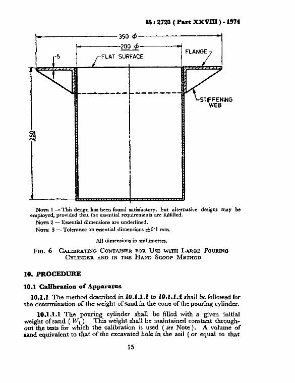
8.3 Cylindrical Calibrating Container - with internal diameter of 200 mm and an internal depth of 250 mm ( see Note 1 under 4.2.2 ) of the type illustrated in Fig. 6 fitted with a Range 75 mm wide and about 5 mm thick surrounding the open end. The volume of the container should be given to an accuracy of 0.15 percent.
8.4 Balance-accurate to 1 g.
8.5 Plane Surface - a glass plate or other plane surface about 600 mm square and 10 mm thick or larger.
8.6 Metal Containers-to collect the excavated soil and to take the supply of sand to fill the pouring cylinder. This may be provided with a suitable cover.
8.7 Metal Tray with Central Hole -a metal tray 450 mm square and 50 mm deep with a 200 mm dia hole in the centre.
9. MATERIAL (SAND)
9.1 Clean, uniformly graded natural sand passing the l*OO-mm IS Sieve and retained on the 600-micron IS Sieve shall be used. It shall be free from organic matter, and shall have been oven dried and stored for a suitable period to allow its water content to reach equilibrium with atmospheric humidity ( ice Note under 3.1 ).
14
IS:272G(Pati XXVIII)-1974
350 9
1 F 200 @
rFLAT SURFACE
Ncrral -This design has been found satisfactory, but alternative designs may. be employed, provided that the essential requirements arc fulfilled.
NOTE 2 - Essential dimensions are underlined.
NATE 3 -Tolerance on essential dimensions f0.I mm.
All dimensions in milliietres.
FIG. 6 CALIBRATING CONTAINER FOR USE WITH LARGE POURING CYLINDER AND IN THE HAND SCOOP METHOD
10. PROCEDURE
10.1 Calibration ofApparatms
10.1.1 The method described in 10.1.1.1 to 10.1.1.4 shall be followed for the determination of the weight of sand in the cone of the pouring cylinder.
10.1.1.1 The pouring cylinder shall be filled with a given initial weight of sand ( WI ) . This weight shall be maintained constant through- out the tests for which the calibration is used ( see Note ). A volume of sand equivalent to that of the excavated hole in the soil ( or equal to that
15
I§ : 2720 ( Part XXVIXI ) - 1974
of the calibrating container ) shall be allowed to run out of the pouring cylinder under gravity. The shutter on the pouring cylinder shall then be closed and the cylinder placed on the plane surface.
NOTE -The total weight of the pouring cylinder and sand is large., so that the method of filling and weighing is to weigh the sand in two or three contamers and tip it into the pouring cylinder before using. Care shall be taken to see that the same constant initial weight as is used in calibrating the apparatus is used for each density measurement. Sufficient sand should be used to leave about 4 to 5 kg of sand in the pouring cylinder after the test is completed.
10.1.1.2 The shutter on the pouring cylinder shall be opened and sand allowed to run out. When no further movement of sand takes place in the cylinder the shutter shall be closed and the cylinder removed carefully.
10.1.1.3 The sand that has filled the cone of the pouring cylinder shall be collected and weighed to the nearest 0.1 percent of its total weight.
10.1.1.4 These measurements shall be repeated at least three times and mean weight ( W, ) taken.
10.1.2 The method ‘described in 10.1.2.1 to 10.1.2.3 shall be followed for the determination of the bulk density of the sand ( y, ).
10.1.2.1 The internal volume ( V) in ml of the calibrating container shall be determined by the weight of water contained in the container when filled to the brim ( see Note under 10.2.2 ).
10.1.2.2 The calibrating container should stand on a large tray during the procedure to collect the sand overflowing from the cone wheti the cylinder is removed. The pouring cylinder shall be placed concentrically ?n the top of the calibrating container and filled with the constant weight of sand ( W, ) as in 10.1.1.1. The shutter on the pouring cylinder shall be closed during this operation. The shutter shall be opened and the sand allowed to run out. When no further movement of the sand takes place in the cylinder the shutter shall be closed. The pouring cylinder shall be removed and the sand remaining in it weighed to the nearest O-1 percent of its initial weight.
10.1.2.3 These measurements shall be repeated at least three times, and the mean weight ( W, ) taken ( see Note under 4.1.2.3 ).
10.2 The method given in 10.2.1 to 10.2.4 shall be followed for the measurement of soil density.
10.2.1. A flat area, approximately 60 cm’, at the place at which the soil is to be tested shall be exposed and trimmed down to a level surface.
10.2.2 The metal tray with a central hole shall be laid on the prepared surface of the soil with the hole over the portion of the soil to be tested. The hole in the soil shall then be excavated using the hole in the tray as a pattern, to the depth of the layer to be tested up to a maximum of 250 -
16

IS : 2720 ( Part XXVIII ) - 1974
( see Note ). The excavated soil shall be carefully collected, leaving no loose material in the hole, and weighed to the nearest gram ( W, ). The metal tray shall be removed before the pouring cylinder is placed in position over the excavated hole.
NOTE - If for any reason it is necessary to excavate holes to depths other than 250 mm the calibrating container should be replaced by one, the depth of which is the same as the hole excavated or its effective depth reduced to that of the hole excavated.
10.2.3 A representative sample of the excavated soil shall be placed in an air-tight container and its water content ( w ) determined by the method specified in IS : 2720 ( Part II )-1973*.
10.2.4 The pouring cylinder filled with the constant weight of sand ( W, ) as in 10.1.1.1, shall be placed so that the base of the cylinder covers the hole concentrically. The shutter on the pouring cylinder shall be closed during this operation. The shutter shall then be opened and sand allowed to run out. When no further movement of the sand takes place the shutter shall be closed. The cylinder shall be removed and the sand remaining in it weighed to the nearest 0.1 percent of its initial weight ( W, ) ( set Note under 4.2.4 ).
11. CALCULATIONS
11.1 The calculations shall be done as laid down in 5.
11.2 For medium- and coarse-grained soils containing appreciable gravel fraction ( plus 4.75-mm IS Sieve ) the water content and dry density shall be determined as given in Appendix B.
12. REPORTING OF RESULTS
12.1 The results shall be reported as specified in 6 except that the method used for obtaining the test results shall be stated as large pouring cylinder method.
12.2 The results of the test shall be recorded suitably. A recommended pro firma for the record of test results is given in Appendix A.
*Methods of tat for soils: Part II Determination of water content ( ~econdfev&rc ).
17

IS : 2720 ( Part XXVIII ) - 1974
APPENDIX A
( Clauses 6.3 and 12.2 )
DETERMINATION OF DRY DENSITY OF SOIL, IN-PLACE, BY SAND REPLACEMENT
( SmaU Pouring Cylinder/Large Pouring Cylinder )
A-l. The test results for the two methods, namely, small pouring cylinder and large pouring Gylinder may be tabulated as given below using the appropriate symbols and words in each case:
Project: Tested by:
Location:. Date:
State whether steel core cutter was used.
Calibration
1. Mean weight of sand in cone ( of pouring cylinder ) ( W, ), in g
2. Volume of calibrating container ( V ), in ml
3. Weight of sand ( + cylinder ) before pouring ( WI ), in g
4. Mean weight of sand ( + cylinder ) after pouring ( W, ), in g
5. Weight of sand to fill calibrating container ( w, = WI - W, -- W, ), in g
6. Bulk density of sand y, =$ x 1000 kg/m3
18

IS : 2720 ( Part XXVIII ) - 1974
Measurement of Soil Density
1. Determination No.
2. Weight of wet soil from hole ( W, ), in g
3. Weight of sand ( + cylinder ) before pouring ( W, ), in g
_ 4. Weight of sand ( + cylinder ) after pouring ( W4 1, in g
5. Weight of sand in hole ( W, = WI- W,- W, ), in g
6. Bulk density ya =2 x yr kg/m’ b
7. Water content container No.
8. Weight of soil for water content determi- nation, in g
9. Weight of oven dried soil, in g
10. Water content ( w ), percent
11. Dry density yd = sw kg/m’
APPENDIX B ( Ckruse 11.2 )
DETERMINATION OF WATER CONTENT AND DRY DENSITY OF MEDIUM- AND COARSE-GRAINED SOILS CONTAINING
APPRECIABLE GRAVEL FRACTION ( PLUS +75-mm IS SIEVE )
B-l. IN-PLACE BULK DENSITY
B-l.1 The in-place bulk density ( yb ) of the soil shall be determined as described in Section 2.
B-2. PROCEDURE FOR DETERMINATION OF VOLUME AND WATER CONTENT
B-2.1 After obtaining the wet weight ( W, ) of the total material removed from the hole, the soil shall be separated into plus 4.75-mm fraction
19

IS : 2720 ( Part XXVIII ) - 1974
( gravel) and minus 4.75 mm fraction by the 4*75-mm IS Sieve. T?_is should be done rapidly to avoid loss of water.
NOTE - If this test is for construction control, the fraction passing the 4’75mm IS Sieve should be placed in an air-tight container for further tests.
B-2.2 The fraction retained on the 4*75-mm IS Sieve ( gravel ) shall be washed on the sieve using a minimum of water, blotted dry with a towel to a wet surface-dry condition and weighed ( W, ).
b2.3 The volume of the gravel ( V, ) in a wet surface-dry condition, shall then be determined by displacement of water from a siphon-container from which the over-flow can be measured, or by weighing in air and in water. The specific gravity ( G, ) of the gravel particles should then be computed.
NOTE - For construction control, the volume of gravel need not be measured every time a test is made. After several tests have shown that the specific gravity of the gravel from a particular source is virtually constant, the specific gravity may be assumed and the volume computed.
B-2.4 The wet gravel ( W’, ) shall be placed in an oven and the oven-dry weight and water content ( w, ) shall be determined.
B-2.5 The water content ( w, ) in percent of the soil fraction passing the 4.75-mm IS Sieve shall also be determined by oven-drying a representative sample.
B-3. CALCULATIONS
B-3.1 Further calculations should be carried out as follows:
a) In-place bulk density ya W, = Volume of hole
b) Wet weight of minus 4*75-mm soil = W, - W, c) V&ne of minus 4*75-mm soil = Volume of hole - Y,
d) Wet density of minus4*75-mm soil = s
(a) e) Dry weight of minus 4*75-mm soil = -p 1 + w,/lOO
f) Dry density of minus 4*75-mm soil = (c) 1 + WJIOO
g) Dry weight of total material ( soil + gravel ) = W’, f (dj
h) Water content ( wT) of total material, percent = _!%_cf, x 100
(f) j) Percentage of gravel in the
material on a dry weight basis =w)I x 100 (f)
k) Dry density of the total material = ” 1 + rur-/lOO
20
IS t 2720 ( Part XXVIlI ) - 1974
* i Continued from page 2 )
iW.hnbcrs
SHRI H. K. &HA
Rgresrnting
&iRr N. N. &XA’ITACHARAYA Geologists’ Syndicate Pvt Ltd, Calcutta
(Alternate ) SHRI S. K. GULHATI Indian Institute of Technology. New Delhi SHRI G. R. S. JAM Central Building Research Institute ( CSIR ), Roorkee
SHIU Atwu Smon ( Alternate) SEW 0. P. MALHOTRA Buildinns & Roads Research Laboratory. Chandinarh
DR I. S. UPPAL (Alternate 1 DRV.V.S.~O -‘mm ’ United Technical Consultants Pvt Ltd, New Delhi
SHR~ K. K. GUPTA ( Altemuta ) MAJ K. M. S. SNWI Engineer-in-Chief’s Branch, Army Headquarters SHRJ H. C. V~R~A Associated Instrument Manufacturers ( India ) Pvt
Ltd. New Delhi SHRI M. N. BALIOA ( Alternate )
21

BUREAU OF INDIAN STANDARDS
Manak Bhavan, 9 Bahadur Shah Zafar Marg, NEW DELHI 110002 Telephones: 323 0131, 323 3375, 323 9402 Fax :91113234062, 91113239399,91113239362
Telegrams : Manaksanstha (Common to all OftIces)
centrd Laboratory: 181_phone
Plot No. 2019, Site IV, Sahibabad Industrial Area, SAHIBABAD 201010 0-77 00 32
Regiond Oftices:
Central : Manak Bhavan, 9 Bahadur Shah Zafar Marg, NEW DELHI 110?02 323 76 17
‘Eastern : l/l4 CIT Scheme VII M, V.I.P. Road, Maniktola, CALCUTTA700054 337 66 62
Northern : SC0 331336. Sector 34-A, CHANDIGARH 160022 603643
Southern : C.I.T. Campus, IV Cross Road, CHENNAI 600113 235 23 15
tWestern : Manakalava, EQ Behind Mar01 Telephone Exchange, Andheri (East), 632 92 95 MUMBAI 400093
Branch 0tflc.s: I
‘Pushpak’, Nurmohamed Shaikh Marg, Khanpur, AHMEDABAD 36ooOl 5501346
SPeenya Industrial Area, 1st Stage, Bangalore-Tumkur Road, 639 49 55 BANGALORE 560056
Gangotri Complex, 5th Floor, Bhadbhada Road, T. T. Nagar, BHOPAL 462003 55 40 21
Plot No. 62-63, Unit VI. Ganga Nagar, BHUBANESHWAR 751001 40 36 27
Kalaikathir Buildings, 670 Avinashi Road, COIMBATORE 641037 21 01 41
Plot No. 43, Sector 16 A, Mathura Road, FARIDABAD 121001 6-26 66 01
Savitri Complex, 116 G. T. Road, GHAZIABAD 201001 6-71 19 96
S3i5 Ward No. 29. R. G. Barua Road, 5th By-lane, GUWAHATI 761003 541137
5-6-56C, L. N. Gupta Marg, Nampally Station Road, HYDERABAD 500001 20 10 63
E-52, Chitarahjan Marg. C-Scheme, JAIPUR 302001 37 29 25
117/416 B, Sarvodaya Nagar, KANPUR 206005 21 66 76
Seth Bhawan, 2nd Floor, Behind Leela Cinema, Naval Kishore Road, 23 69 23 LUCKNOW 226001
Patliputra Industrial Estate, PATNA 600013
T. C. No. 1411421, University P. 0. Palayam. THIRUVANANTHAPURAM 695034
NIT Building, wand Floor, Gokulpat MarKet, NAGPUR 440010
Institution of Engineers ( India ) Building, 1332 Shivaji Nagar, PUNE 411005
26 23 05
6 21 17
52 51 71
32 36 35
‘Sales Office is at 5 Chowringhes Approach, P 0. Princep Street, CALCUlTA 700072
*Sales Office is at Novelty Chambers, Grant Road, MUdBAl 400007
*Sales Office is at ‘F’ Block, Unity Building, Narashimaraja Square, BANGALORE 560002
27 10 65
309 65 26
222 39 71
Printed al New InrJis Prk~n~ Press, Khur)s. lndia