IRS-1C/1D/P6 DIGITAL DATA PRODUCTS FORMAT … control and data sheet 1. ... title and sub-title:...
26
IRS-1C/1D/P6 DIGITAL DATA PRODUCTS FORMAT FOR REVISION C FAST FORMAT PRODUCTS May, 2003 Data Products Software Division Signal and Image Processing Group Space Applications Center,ISRO,Ahmedabad – 380 015
-
Upload
vuongduong -
Category
Documents
-
view
215 -
download
0
Transcript of IRS-1C/1D/P6 DIGITAL DATA PRODUCTS FORMAT … control and data sheet 1. ... title and sub-title:...

IRS-1C/1D/P6 DIGITAL DATA PRODUCTS FORMAT
FOR REVISION C FAST FORMAT PRODUCTS
May, 2003
Data Products Software Division Signal and Image Processing Group
Space Applications Center,ISRO,Ahmedabad – 380 015

2
DOCUMENT CONTROL AND DATA SHEET
1. Report No. and date: IRS-P6/DP/SAC/SIIPA/SIPG/TN-05/MAY 2002 2. Title and sub-title: IRS-1C/1D/P6 DIGITAL DATA PRODUCTS FORMAT FOR REVISION C FAST FORMAT PRODUCTS 3. Type of Report : TECHNICAL 4. No. of pages : 26 5. Authors : Sk.Sazid Mahammad,
IRS DATA PRODUCTS TEAM SIPG GROUP SPACE APPLICATION CENTRE AHMEDABAD 6. Abstract : THIS DOCUMENT CONTAINS THE FORMAT FOR IRS-1C/1D/P6 FAST FORMAT DIGITAL DATA PRODUCTS 7. Key words : FAST FORMAT, HEADER FILE,IMAGE FILE, BLOCKED RECORD,ADMINISTRATIVE RECORD, RADIOMETRIC RECORD, GEOMETRIC RECORD, MAP PROJECTIONS, FORMAT LAYOUTS. 8. Security
Classification : UNRESTRICTED
3
IRS-1C/1D/P6 DIGITAL DATA PRODUCTS FORMAT
FOR REVISION C FAST FORMAT PRODUCTS
TABLE OF CONTENTS
1.0 INTRODUCTION......................................................................................................................................................4 1.1 GENERAL FORMAT RULES..............................................................................................................................4 1.2 GENERAL FORMAT DESCRIPTION ...................................................................................................................4
1.2.1 HEADER FILE..................................................................................................................................................4 1.2.2 IMAGE FILES ...................................................................................................................................................5 1.2.3 BLOCKED RECORDS ......................................................................................................................................5
2.0 DETAILED FORMAT DESCRIPTION 2.1 HEADER FILES ................................................................................5 2.1.1 ADMINISTRATIVE RECORD...........................................................................................................................5 2.1.2 RADIOMETRIC RECORD................................................................................................................................7 2.1.3 GEOMETRIC RECORD....................................................................................................................................7
2.2 SOFTWARE : .........................................................................................................................................................9 APPENDIX-A : MAP PROJECTIONS .........................................................................................................................10 APPENDIX- B-1 : EARTH ELLIPSOIDS ......................................................................................................................11 APPENDIX- B-2: ELLIPSOID AND DATUM MNEMONICS ..........................................................................................12 APPENDIX – C : USGS PROJECTION PARAMETERS .............................................................................................13 APPENDIX-D : FAST FORMAT HEADER FILE RECORD FORMAT TABLES ..............................................................16 APPENDIX-E : FAST FORMAT LAYOUT ...................................................................................................................26

4
IRS-1C/1D/P6 DIGITAL DATA PRODUCTS FORMAT
FOR REVISION C FAST FORMAT PRODUCTS
1.0 INTRODUCTION This document describes the format for IRS-1C/1D/P6 fast format digital data products. 1.1 GENERAL FORMAT RULES 1. All field definitions strictly follow American National Standard Institute (ANSI) and
International Organization for Standardization (ISO) standards.
2. Only Band Sequential (BSQ) image structure is supported because data to be written to tape is made available a single band at a time .
3. Image files consist of a single band of data. 4. A digital product is referred to as a volume set. Individual media (8mm DAT, CD) are referred
to as volumes. A volume set may have one or more volumes, depending on image size and output media capacity.
1.2 GENERAL FORMAT DESCRIPTION The Fast Format (Version C) volume set contains a Header File and Image Files. 1.2.1 HEADER FILE The first file on each volume, a Read-Me-First file, contains header data. It is in American Standard Code for Information Interchange (ASCII) format, confirming to ANSI and ISO standards. Alphanumeric fields are left justified and numeric fields are right justified. Dates are given in yyyy ddmm format (full year, day-of-month and month format). All processing options, radiometric calibration, geometric characteristics and map projection information for the product are contained in this file. Appendix D contains a table of the entries in the Header File. The table breaks the information into 80 byte units with a carriage return as the eightieth character, allowing convenient printing of the file. For this reason, each 80 byte unit is referred to as a line. The table lists the field number in each record, the start and stop byte number, a FORTRAN format representation and a short text describing the field contents.

5
1.2.2 IMAGE FILES Each image file contains one band of image data. There are no header records within the image file, nor are there prefix and/or suffix data in the individual image records. Image data may be blocked or unblocked. 1.2.3 BLOCKED RECORDS This blocking results in writing fewer End-of-Record gaps on the tape and allows more data to be written to the tape. 2.0 DETAILED FORMAT DESCRIPTION 2.1 HEADER FILES The Header File contains three 1536-byte ASCII records. The first record is the Administrative Record which contains information that identifies the product, the scene and the data specifically needed to ingest the imagery from the digital media. In order to import the image data, it is necessary to read entries in the Administrative Record. The second record is the Radiometric Record which contains the coefficients needed to convert the scene digital values into at-satellite spectral radiance. The third record is the Geometric Record which contains the scene geodetic location information. In order to align the imagery to other data sources, it will be necessary to read entries in the Geometric Record. The accompanying tables in Appendix D describe the format of the three records, including the number of bytes, the FORTRAN format statement and a brief description of each field in the header file. All alphanumeric fields are left justified, and all numeric fields right justified. Fields of fixed (constant) values are represented with capital letters in quotes (e.g., "PRODUCT="). Variable fields are represented with lower case letters. In both fixed and variable fields, blank spaces are indicated by the lower case"b" character. All three records in the Header File have a carriage return every eightieth character. 2.1.1 ADMINISTRATIVE RECORD The first field in this record contains the Product ID, a unique identifier for the product as ordered by the customer. The remainder of the initial two lines in this record describe the source of the image with pertinent sensor parameters. The next six lines are replicates of the first two without the Product ID. These are growth regions allowing for mosaic products containing up to four images and co-registered Panchromatic and multi-spectral imagery. These products are proposed and but not yet implemented. Line nine describes the type of product contained on the media i.e., size and orientation. Line ten describes the characteristics of the processing: i.e., level of geometric correction and resampler used.

6
The remainder of the Administrative Record contains the critical fields required to import the image data to computer memory. For unblocked data (8mm and CD-ROM), ingest of the imagery requires knowledge of the contents of fields 83 (pixels per line), 85 (Line per Band on this volume), 87 (No. of lines in output image) and 105 (Bands Present). It is necessary to count the number of non-blank entries in the Bands Present field to get the count of the number of bands. Each character (byte) in this field will have an ASCII character with the band label, usually a number. For IRS-1C/1D/P6 the values are 2, 3, 4, 5 for LISS-3,2,3,4 for LISS-4,3,4 for WiFS and 2,3,4,5 for AWiFS and P for PAN . The sequence terminates in a blank. For blocked data, fields 91 (Start Line), and either 93 (Blocking Factor) or 95 (Record Length) and 87 (Number of lines in the output image) are also needed. Note that the (blocked) record length is equal to the blocking factor times the number of pixels per line. One may choose the parameter that best fits their system software interface. Fields 79 and 81 (Volume #/# in Set) relate to which volume number in a set and field 100 indicates Bits per Pixel. Field 73 (bytes 741-751) in Line 10 contains the level of processing that has been performed on the image.
RAW
No corrections applied
RADIOMETRIC
Radiometric corrections only
SYSTEMATIC
Radiometric and geometric corrections using spacecraft system data only.
PRECISION
Radiometric and geometric corrections using spacecraft system data along with control points.
TERRAIN
Radiometric and geometric corrections using spacecraft system data, along with control points and digital elevation model (DEM)
Field 75 (bytes 765-766) in Line 10 contains the resampling algorithm that has been applied to the image. CC = Cubic convolution NN = Nearest neighbour SI=Sinc16 KI=Kaiser Field 83 (bytes 843-847) in Line 11 contains the number of image pixels on each image line of each image band on the tape. Field 85 (bytes 865-869) in Line 11 contains the number of image lines per band on this volume (This is the number of lines in each image file for tapes containing one or more complete image files.). Field 87 (Bytes 871-875) contains the number of image lines for the entire band (The band may be split across multiple volumes). These are right-justified numeric fields.

7
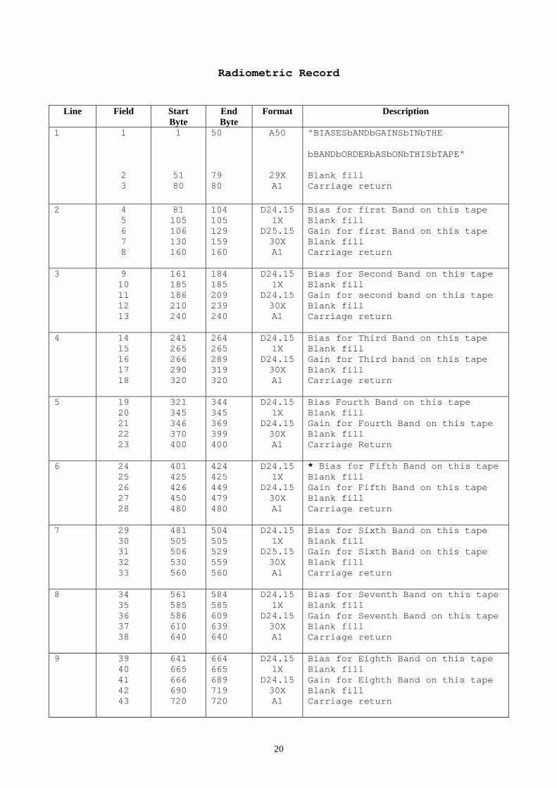
Field 91 (bytes 895-899) in Line 12 identifies the first image line on this tape volume. This is "b1" unless the tape is the second or higher numbered volume of a multi-volume set (e.g. fields 79 & 81 are "b2/b2"). In this case it is the line number in the complete image of the first image line on the tape ((nominally N/2 + 1 for two-tape sets, where N is the total number of lines in the image)). This is a right-justified ASCII numeric field. Field 93 (bytes 918-919) in Line 12 contains the blocking factor used to minimize the number of CCT tapes required to accommodate the image set. This field is always "1" for 8mm tapes. (See Blocking Factor explanation under Image Files). Field 95 (bytes 936-940) in Line 12 contains the physical tape record length. The value is right justified in an ASCII numeric field. The number of pixels (samples) per image line can be determined by dividing this field in the value in Field 93 or by directly reading field 83 (bytes 843-847). For two byte data like AwiFS (IRS-P6) Pixels = RecordLength/(BlockingFactor * BytesPerPixel). Field 100 (bytes 984-985) in Line 13 contains the integer number of bits per pixel that is used in the output media to represent the digital value of each individual pixel. (This value may be different from Field 102). Field 102 (bytes 1012-1013) in Line 13 contains the integer number of bits per pixel that each individual pixel was quantized the satellite instrument. (This value may be different from field 100) IRS-1C panchromatic data is transmitted as six bit pixels, while the digital products are always produced are always produced with eight bit pixels. Field 106 (bytes 1056-1087) in Line 14 contains the band identifiers for the image files on the tape volume. This field is composed of thirty-two- one-byte sub-fields containing from one to thirty-two of the band identifies (i.e., "234b" for full IRS-1C LISS-3 data sets or "Pb" for IRS-1C panchromatic data sets). The band identifiers are listed in the order in which the image files appear on the tape and are single character fields. So the leftmost character (byte 1056) must be non-zero. The sequence ends with trailing blanks. 2.1.2 RADIOMETRIC RECORD Fields 4-41 (bytes 81-689) contains the coefficients needed to convert scene digital values to at-satellite spectral radiances. Conversion formula for Digital Count to radiance is as follows. Lrad = (DN/MaxGray)*(Lmax – Lmin) + Lmin. Lrad : Radiance for a given DN value. DN : Digital Count MaxGray : IRS-1C/1D : 63 for PAN & 127 for WiFS & LISS-3 for Raw Products only. 255 for Corrected products. For IRS-P6 : 127 for LISS-4 and LISS-3, 1023 for AWiFS for raw products only. 255 for LISS-3&4,1023 for AWiFs for corrected products Lmin/Lmax(Bias/Gain) : Minimum/Maximum radiance value for a given band supplied as bias and gain respectively. 2.1.3 GEOMETRIC RECORD Line 1 contains the map projection (field 3), Earth ellipsoid (field 5) and datum (field 7) used in producing the product. Appendix A contains the list of supported map projections and Appendix B contains the list of supported Earth ellipsoids and comments about the datum. Products are not
8
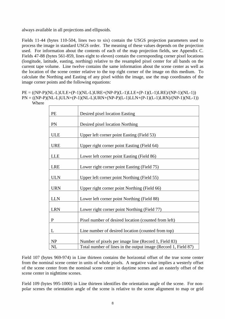
always available in all projections and ellipsoids. Fields 11-44 (bytes 110-504, lines two to six) contain the USGS projection parameters used to process the image in standard USGS order. The meaning of these values depends on the projection used. For information about the contents of each of the map projection fields, see Appendix C. Fields 47-88 (bytes 561-859, lines eight to eleven) contain the corresponding corner pixel locations (longitude, latitude, easting, northing) relative to the resampled pixel center for all bands on the current tape volume. Line twelve contains the same information about the scene center as well as the location of the scene center relative to the top right corner of the image on this medium. To calculate the Northing and Easting of any pixel within the image, use the map coordinates of the image corner points and the following equations: PE = ((NP-P)(NL-L)ULE+(P-1)(NL-L)URE+(NP-P)(L-1)LLE+(P-1)(L-1)LRE)/(NP-1)(NL-1)) PN = ((NP-P)(NL-L)ULN+(P-1)(NL-L)URN+(NP-P)(L-1)LLN+(P-1)(L-1)LRN)/(NP-1)(NL-1)) Where
PE
Desired pixel location Easting
PN
Desired pixel location Northing
ULE
Upper left corner point Easting (Field 53)
URE
Upper right corner point Easting (Field 64)
LLE
Lower left corner point Easting (Field 86)
LRE
Lower right corner point Easting (Field 75)
ULN
Upper left corner point Northing (Field 55)
URN
Upper right corner point Northing (Field 66)
LLN
Lower left corner point Northing (Field 88)
LRN
Lower right corner point Northing (Field 77)
P
Pixel number of desired location (counted from left)
L
Line number of desired location (counted from top)
NP
Number of pixels per image line (Record 1, Field 83)
NL Total number of lines in the output image (Record 1, Field 87) Field 107 (bytes 969-974) in Line thirteen contains the horizontal offset of the true scene center from the nominal scene center in units of whole pixels. A negative value implies a westerly offset of the scene center from the nominal scene center in daytime scenes and an easterly offset of the scene center in nighttime scenes. Field 109 (bytes 995-1000) in Line thirteen identifies the orientation angle of the scene. For non-polar scenes the orientation angle of the scene is relative to the scene alignment to map or grid

9
north. For non polar map oriented scenes this field should be zero. A negative angle implies a clockwise rotation of the scene to align with map north whereas a positive angle implies a counterclockwise rotation of the scene to align with map north. To calculate the orientation angle of any image use the following equation:
ANGLE
arctan (NORTHDIFE/EASTDIFF)
NORTHDIFF
URNORTH – ULNORTH
EASTDIFF
UREAST - ULEAST
URNORTH
Upper right corner point Northing (field 66)
ULNORTH
Upper left corner point Northing (field 55)
UREAST
Upper right corner point Easting (field 64)
ULEAST
Upper left corner point Easting (field 53)
Field 113 (bytes 1062-1065) in Line fourteen contains the sun elevation in degrees for the scene center location at the scene center acquisition time. This angle specifies the solar parallel of altitude on the celestial sphere as referenced from the celestial horizon of the scene center. Field 115 (bytes 1086-1090) contains the sun azimuth (west) in degrees for the scene center location at the scene center acquisition time. This angle specifies the vertical circle (West) on which the sun's location is measured from the principal vertical circle of the scene center. 2.2 SOFTWARE : The cartographic software package used in processing the digital imagery is described in the following references: General Cartographic Transformation Package (GCTP) Software Reference NOAA Technical Report NOS 124 CGS 9 General Cartographic Transformation Package GCTP, Version II Atef A Elassal - February 1987 U.S.Dept. of Commerce National Geodetic Information Center, NOAA Rockville, MD 20852 USGS Map Projection Reference Map Projections - A Working Manual U.S. Geological Survey Professional Paper 1395 (Supersedes USGS Bulletin 1532) John P. Snyder - 1987 USGS Map Sales P.O.Box 25286 Denver, CO 80225

10
APPENDIX-A : Map Projections This appendix contains the map projections used in EOSAT's products. This list of map projections shows the name and the identifier used in Record 3. Field 3 of the header file.
Projection Name Mnemonic Universal Transverse Mercator
UTM
State Plane Coordinate System
SPCS
Albers Conical Equal Area
ACEA
Lambett's Conformal Conic
LCC
Mercator
MER
Polar Stereographic
PS
Polyconic
PC
Equidistant Conic (Type A & B)
EC
Transverse Mercator (Gauss-Krugger)
TM
Transverse Mercator
TM
Stereographic
SG
Lamberts Azimuthal Equal Area
LAEA
Azimuthal Equidistant
AE
Gnomonic
GNO
Orthographic
OG
General Vertical Near-Side Perspective
GVNP
Sinusoidal
SIN
Equirectangular (Plate Career)
ER
Miller Cylindrical
MC
Van Der Grintern I
VDG
Oblique Mercator (Type A & B)
OM
Space Oblique Mercator
SOM
11
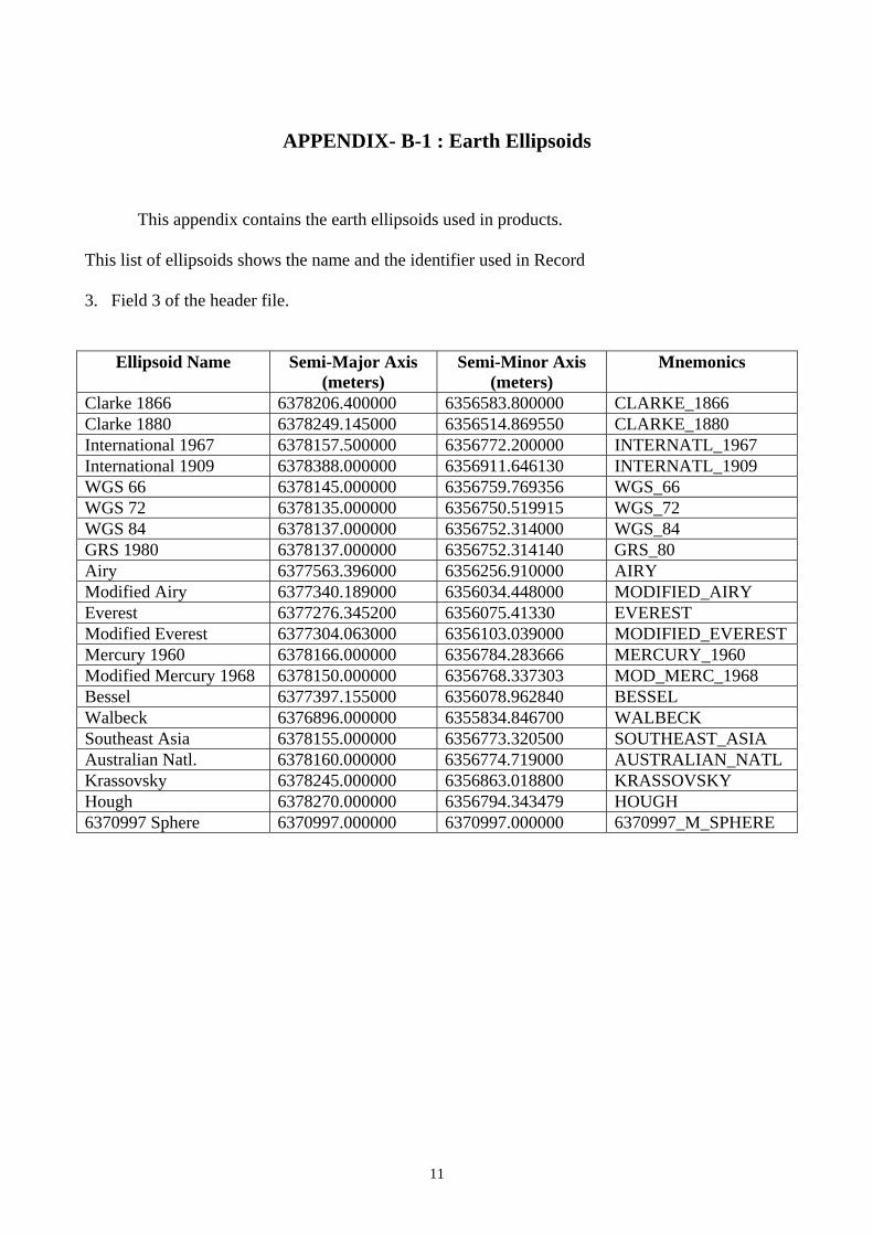
APPENDIX- B-1 : Earth Ellipsoids
This appendix contains the earth ellipsoids used in products. This list of ellipsoids shows the name and the identifier used in Record 3. Field 3 of the header file.
Ellipsoid Name
Semi-Major Axis (meters)
Semi-Minor Axis (meters)
Mnemonics
Clarke 1866 6378206.400000 6356583.800000 CLARKE_1866 Clarke 1880 6378249.145000 6356514.869550 CLARKE_1880 International 1967 6378157.500000 6356772.200000 INTERNATL_1967 International 1909 6378388.000000 6356911.646130 INTERNATL_1909 WGS 66 6378145.000000 6356759.769356 WGS_66 WGS 72 6378135.000000 6356750.519915 WGS_72 WGS 84 6378137.000000 6356752.314000 WGS_84 GRS 1980 6378137.000000 6356752.314140 GRS_80 Airy 6377563.396000 6356256.910000 AIRY Modified Airy 6377340.189000 6356034.448000 MODIFIED_AIRY Everest 6377276.345200 6356075.41330 EVEREST Modified Everest 6377304.063000 6356103.039000 MODIFIED_EVEREST Mercury 1960 6378166.000000 6356784.283666 MERCURY_1960 Modified Mercury 1968 6378150.000000 6356768.337303 MOD_MERC_1968 Bessel 6377397.155000 6356078.962840 BESSEL Walbeck 6376896.000000 6355834.846700 WALBECK Southeast Asia 6378155.000000 6356773.320500 SOUTHEAST_ASIA Australian Natl. 6378160.000000 6356774.719000 AUSTRALIAN_NATL Krassovsky 6378245.000000 6356863.018800 KRASSOVSKY Hough 6378270.000000 6356794.343479 HOUGH 6370997 Sphere 6370997.000000 6370997.000000 6370997_M_SPHERE

12
APPENDIX- B-2: Ellipsoid and Datum Mnemonics Ellipsoid Name
Ellipsoid Mnemonic Possible Datum Name Datum
Mnemonics Clarke 1866 CLARKE_1866 Datum_North_American_D
atum_1927 NAS-E
Clarke 1880 CLARKE_1880 Datum_Adindan ADI-M International 1967 INTERNATL_1967 Datum_New_Zealand_Geo
detic_Datum_1949 GEO
International 1909/1924
INTERNATL_1909 Datum_European_Datum_1950
EUR-M
WGS 66 WGS_66 WGS_66 WGS_66 WGS 72 WGS_72 WGS_72 WGS_72 WGS 84 WGS_84 WGS_84 WGS_84 GRS 1980 GRS_80 Datum_North_American_D
atum_1983 NAR-B
Airy AIRY Datum_OSGB_1936 OGB_M Modified Airy MODIFIED_AIRY Datum_TM65 IRL Everest EVEREST Datum_Kalianpur IND-I Modified Everest MODIFIED_EVERE
ST Datum_Kalianpur IND-I
Mercury 1960 MERCURY_1960 NOT DEFINED Modified Mercury 1968
MOD_MERC_1968 NOT DEFINED
Bessel BESSEL Datum_Tokyo TOY-M Walbeck WALBECK Datum_European_Datum_1
950 EUR-M
Southeast Asia SOUTHEAST_ASIA Datum_Southasia SOA Australian Natl. AUSTRALIAN_NAT
L Datum_Australian_Geodetic_datum_1984
AUG
Krassovsky KRASSOVSKY Datum_Pulkovo_1942 PUK Hough HOUGH Datum_Wake-
Eniwetok_1960 ENW
6370997 Sphere 6370997_M_SPHERE NOT DEFINED

13
APPENDIX – C : USGS Projection Parameters Fast Format Revision C Supports 17 USGS projections. For all projections except State Plane, USGS parameters 1 and 2 are semi major and minor axes of the requested earth ellipsoid.
* Not every parameter will be used by the designated projection. * If a parameter is not used the field for the parameter will be initialized to Zero. * All latitude and longitude fields will be specified in Decimal Degree (floating point) * All other fields will be specified as double precision floating point values.
Please note that all co-ordinates for State Plane System contained in the Fast Format is in map metres (not in feet). C1(U) Universal Transverse Mercator ( UTM ) Parameter 3* UTM Zone number ( Optional ) C2(A) Albers Conical Equal Area ( ACEA ) Parameter 3 Latitude of first Standard Parallel Parameter 4 Latitude of second Standard Parallel Parameter 5 Longitude of central meridian Parameter 6 Latitude of projection's Origin Parameter 7 False Easting (in metres) Parameter 8 False Northing (in metres) C3(L) Lamberts Conformal Conic ( LCC ) Parameter 3 Latitude of first Standard Parallel Parameter 4 Latitude of second Standard Parallel Parameter 5 Longitude of central meridian Parameter 6 Latitude of projection's Origin Parameter 7 False Easting (in metres) Parameter 8 False Northing (in metres) C4(M) Mercator ( Mer ) Parameter 5 Longitude of central meridian Parameter 7 False Easting (in metres) Parameter 8 False Northing (in metres) C5(D) Polar Stereographic ( PS ) Parameter 5 Longitude directed straight down below pole of map Parameter 6 Latitude of true scale Parameter 7 False Easting (in metres) Parameter 8 False Northing (in metres)

14
C6(P) Polyconic ( POL ) Parameter 5 Longitude of central meridian Parameter 6 Latitude of projection's Origin Parameter 7 False Easting (in metres) Parameter 8 False Northing (in metres) C7(T) Tranverse Mercator ( TM ) Parameter 3 Scale Factor at central meridian Parameter 5 Longitude of central meridian Parameter 6 Latitude of projections's origin Parameter 7 False Easting (in metres) Parameter 8 False Northing (in metres) C8(H) Stereographic ( SG ) Parameter 5 Longitude of central meridian Parameter 6 Latitude of centre of projection Parameter 7 False Easting (in metres) Parameter 8 False Northing (in metres) C9(Z) Lamberts Azimuthal Equal Area ( LAEA ) Parameter 5 Longitude of central meridian Parameter 6 Latitude of centre of projection Parameter 7 False Easting (in metres) Parameter 8 False Northing (in metres) C10(E) Azimuthal Equidistant ( AE ) Parameter 5 Longitude of central meridian Parameter 6 Latitude of centre of projection Parameter 7 False Easting (in metres) Parameter 8 False Northing (in metres) C11(G) Gnomonic ( GNO ) Parameter 5 Longitude of central meridian Parameter 6 Latitude of centre of projection Parameter 7 False Easting (in metres) Parameter 8 False Northing (in metres)

15
C12(R) Orthographic ( OG) Parameter 5 Longitude of central meridian Parameter 6 Latitude of centre of projection Parameter 7 False Easting (in metres) Parameter 8 False Northing (in metres) C13(N) General Vertical Near-Side Perspective ( GVNP ) Parameter 3 Height of perspective point above sphere Parameter 5 Longitude of centre of projection Parameter 6 Latitude of centre of projection Parameter 7 False Easting (in metres) Parameter 8 False Northing (in metres) C14(I) Sinusoidal ( SIN ) Parameter 5 Longitude of central meridian Parameter 7 False Easting (in metres) Parameter 8 False Northing (in metres) C15(C) Miller Cylinderical ( MC) Parameter 5 Longitude of central meridian Parameter 7 False Easting (in metres) Parameter 8 False Northing (in metres) C16(V) Van Der Grinten ( VDG ) Parameter 5 Longitude of central meridian Parameter 7 False Easting (in metres) Parameter 8 False Northing (in metres) C17(S) Space Oblique Mercator ( SOM ) Parameter 4 Angle of azimuth east of north for central line of projection Parameter 9 Longitude of the ascending Node Parameter 11 Longitude of descending Node C18(K) Tranverse Mercator (Gauss-Krugger)( TM ) Parameter 3 Scale Factor at central meridian Parameter 5 Longitude of central meridian Parameter 6 Latitude of projections's origin Parameter 7 False Easting (in metres) Parameter 8 False Northing (in metres)
16
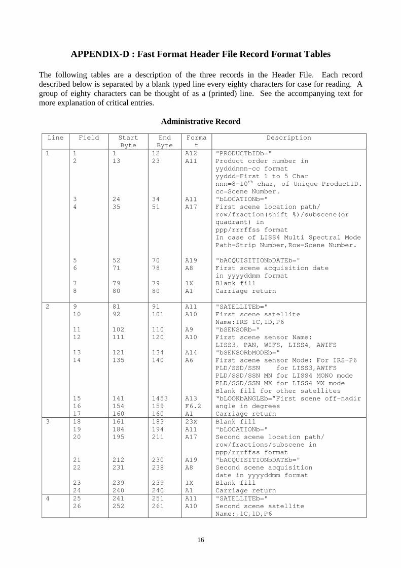
APPENDIX-D : Fast Format Header File Record Format Tables
The following tables are a description of the three records in the Header File. Each record described below is separated by a blank typed line every eighty characters for case for reading. A group of eighty characters can be thought of as a (printed) line. See the accompanying text for more explanation of critical entries.
Administrative Record
Line Field Start Byte
End Byte
Format
Description
1 1 2 3 4 5 6 7 8
1 13 24 35 52 71 79 80
12 23 34 51 70 78 79 80
A12 A11 A11 A17 A19 A8 1X A1
"PRODUCTbIDb=" Product order number in yydddnnn-cc format yyddd=First 1 to 5 Char nnn=8-10th char, of Unique ProductID.cc=Scene Number. "bLOCATIONb=" First scene location path/ row/fraction(shift %)/subscene(or quadrant) in ppp/rrrffss format In case of LISS4 Multi Spectral Mode Path=Strip Number,Row=Scene Number. "bACQUISITIONbDATEb=" First scene acquisition date in yyyyddmm format Blank fill Carriage return
2 9 10 11 12 13 14 15 16 17
81 92 102 111 121 135 141 154 160
91 101 110 120 134 140 1453 159 160
A11 A10 A9 A10 A14 A6 A13 F6.2 A1
"SATELLITEb=" First scene satellite Name:IRS 1C,1D,P6 "bSENSORb=" First scene sensor Name: LISS3, PAN, WIFS, LISS4, AWIFS "bSENSORbMODEb=" First scene sensor Mode: For IRS-P6 PLD/SSD/SSN for LISS3,AWIFS PLD/SSD/SSN MN for LISS4 MONO mode PLD/SSD/SSN MX for LISS4 MX mode Blank fill for other satellites “bLOOKbANGLEb=”First scene off-nadir angle in degrees Carriage return
3 18 19 20 21 22 23 24
161 184 195 212 231 239 240
183 194 211 230 238 239 240
23X A11 A17 A19 A8 1X A1
Blank fill "bLOCATIONb=" Second scene location path/ row/fractions/subscene in ppp/rrrffss format "bACQUISITIONbDATEb=" Second scene acquisition date in yyyyddmm format Blank fill Carriage return
4 25 26
241 252
251 261
A11 A10
"SATELLITEb=" Second scene satellite Name:,1C,1D,P6

17
27 28 29 30 31 32 33
262 271 281 295 301 314 320
270 280 294 30 313 319 320
A9 A10 A14 A6 A13 F6.2 A1
"bSENSORb=" Second scene sensor Name: PAN, WIFS,LISS4,AWIFS "bSENSORbMODEb=" Second scene sensor Mode "bLOOKbANGLEb=" Second scene off-nadir angle in deg. Carriage return
5 34 35 36 37 38 39 40
321 344 355 372 391 399 400
343 354 371 390 398 399 400
23X A11 A17 A19 A8 1X A1
Blankfill "bLOCATIONb=" Third scene location path/ row/fraction/subscene in ppp/rrrffss format "bACQUISITIONbDATEb=" Third scene acquisition date in yyyyddmm format Blank fill Carriage return
6 41 42 43 44 45 46 47 48 49
401 412 422 431 441 455 461 474 480
411 421 430 440 454 460 473 479 480
A11 A10 A9 A10 A14 A6 A13 F6.2 A1
"SATELLITEb=" Third scene satellite Name: 1C,1D,P6 "bSENSORb=" Third scene sensor Name: LISS3, PAN, WIFS,LISS4,AWIFS "bSENSORbMODEb=" Third scene sensor Mode "bLOOKbANGLEb=" Third scene off-nadir angle in degree Carriage return
7 50 51 52 53 54 55 56
481 504 515 532 551 559 560
503 514 531 550 558 559 560
23X A11 A17 A19 A8 1X A1
Blank fill “Blocationb=” Fourth scene location path/ Row/fraction/subscene in Ppp/rrrffss format "bACQUISITIONbDATEb=" Fourth scene acquisition date in yyyyddmm format Blank fill Carriage return
8 57 58 59 60 61 62 63 64 65
561 572 582 591 601 615 621 634 640
571 581 590 600 614 620 633 639 640
A11 A10 A9 A10 A14 A6 A13 F6.2 A1
"SATELLITEb=" Fourth scene satellite Name: 1C,1D,P6 "bSENSORb=" Fourth scene sensor Name: LISS3,PAN, WIFS, LISS4,AWIFS "bSENSORbMODEb=" Fourth scene sensor mode "bLOOKbANGLEb=" Fourth scene off-nadir angle In deg. Carriage return
9 66 641 654 A14 "PRODUCTbTYPEb="

18
67 68 69 70 71
655 673 688 698 720
672 687 697 719 720
A10 A15 A10 22X A1
Product type: MAPbORIENT0dbbbbbb'. 'ORBITbORIENTEDbbbb' "bPRODUCTbSIZEb=" Product size:'FULLbSCENE', 'SUBSCENEbb'. 'MAPbSHEETb'.,'QUADRANT'. blank fill carriage return
10 72 73 74 75 76 77
721 741 752 765 767 800
740 751 764 766 799 800
A20 A11 A13 A2 33X A1
"TYPEbOFbPROCESSINGb=" Type of processing used: 'SYSTEMATICb','PRECISIONbb', 'TERRAINbbbb','RADIOMETRIC", 'RAWbbbbbbbb' "bRESAMPLINGb=" Resampling algorithm used: 'CC','NN',’SI’,’KI’ Blank fill Carriage return
11 78 79 80 81 82 83 84 85 86 87 88 89
801 820 822 823 825 843 848 865 870 871 876 880
819 821 822 824 842 847 864 869 870 875 879 880
A19 I2 A1 I2 A18 I5 A17 I5 A1 I5 4X A1
'VOLUMEb#/#bINbSETb=" Tape volume number in tape set (for multi-volume image)"/" Number of volumes in tape set (for multi-volume image) “bPIXELSbPERLINEb=” Number of pixels per image Line “bLINESbPERb/BANDb=” Number of lines on this volume “/” Number of lines in the output Image Blank fill Carriage return
12 90 91 92 93 94 95 96 97 98
881 895 900 918 920 936 941 954 960
894 899 917 919 935 940 953 959 960
A14 I5 A18 I2 A16 I5 A13 F6.2 A1
"STARTbLINEb#b=" First image line number on this vloume (for multi-volume image) "bBLOCKINGbFACTORb=" Tape blocking Factor "bRECORDbLENGTHb=" Length of physical file record in bytes "bPIXELbSIZEb=" Pixel size in meters Carriage return
13 99 100 101 102 103 104
961 984 986 1012 1014 1040
983 985 1011 1013 1039 1040
A23 I2 A26 I2 26X A1
"OUTPUTbBITSbPERbPIXELb=" Output bits per pixel "bACQUIREDbBITSbPERbPIXELb=" Acquired bits per pixel Blank fills Carriage return
14
105 106 107 108
1041 1056 1088 1103
1055 1087 1102 1111
A15 A32 A14 A9
"BANDSbPRESENTb= Image bands present on this volume “PRODUCTbCODEb=” product code e.g. STPCD02AI ST : Two Char Product Type

19
109 110
1112 1120
1119 1120
8X A1
(e.g ST for STANDARD pathbased) P : 1 Char Projection Code (e.g. Polyconic) C : 1 Char Resampling Option (e.g. Cubic Convolution) D : 1 char Ellipsdoid Code ( e.g. Everest) 0 : Enhancement Code(Zero Always) I : Media Code(e.g. I for DAT, J for CDROM, Z for DISK)
15 111 112 113 114 115 116 117
1121 1133 1145 1153 1171 1183 1200
1132 1144 1152 1170 1182 1199 1200
A12 A12 8X A18 A12 17X A1
“VERSION NO =” DPS software version Blank fill “ACQUISITIONbTIMEb=” time in HH:MM:SS:mmm Blank fill Carriage return
16 118 119 120 121 122 123 124
1201 1221 1233 1236 1255 1265 1280
1220 1232 1235 1254 1264 1279 1280
A20 A12 3X A19 A10 15X A1
“GENERATINGbCOUNTRYb=” Generating Country Name Blank fill “GENERATINGbAGENCYb=” Generating Agency Name Blank Fill Carriage Return
17 125 126 127 128 129 130
1281 1302 1310 1326 1333 1360
1301 1309 1325 1332 1359 1360
A21 A8 A16 A7 27X A1
“GENERATINGbFACILITYb=” facility Name “PRODUCTbENDIANb=” Endian in which product has been generated. e.g. BIG : For product generated with MOTOROLA Architecture(MSB First) LITTLE : For product generated with INTEL Architecture(LSB First) Blank fill Carriage return
18
131 132
1361 1440
1439 1440
79X A1
Blank fill Carriage return
19 133 134
1441 1520
1519 1520
79X A1
Blank fill Carriage return
20 135 136
1521 1536
1535 1536
15X A
"REVbbbbbbbbbbbb" Format version code (A-Z). This document describes Version
20
Radiometric Record
Line Field Start Byte
End Byte
Format Description
1
1 2 3
1 51 80
50 79 80
A50
29X A1
"BIASESbANDbGAINSbINbTHE bBANDbORDERbASbONbTHISbTAPE" Blank fill Carriage return
2 4 5 6 7 8
81 105 106 130 160
104 105 129 159 160
D24.15 1X
D25.15 30X A1
Bias for first Band on this tape Blank fill Gain for first Band on this tape Blank fill Carriage return
3
9 10 11 12 13
161 185 186 210 240
184 185 209 239 240
D24.15 1X
D24.15 30X A1
Bias for Second Band on this tape Blank fill Gain for second band on this tape Blank fill Carriage return
4 14 15 16 17 18
241 265 266 290 320
264 265 289 319 320
D24.15 1X
D24.15 30X A1
Bias for Third Band on this tape Blank fill Gain for Third band on this tape Blank fill Carriage return
5 19 20 21 22 23
321 345 346 370 400
344 345 369 399 400
D24.15 1X
D24.15 30X A1
Bias Fourth Band on this tape Blank fill Gain for Fourth Band on this tape Blank fill Carriage Return
6 24 25 26 27 28
401 425 426 450 480
424 425 449 479 480
D24.15 1X
D24.15 30X A1
* Bias for Fifth Band on this tape Blank fill Gain for Fifth Band on this tape Blank fill Carriage return
7 29 30 31 32 33
481 505 506 530 560
504 505 529 559 560
D24.15 1X
D25.15 30X A1
Bias for Sixth Band on this tape Blank fill Gain for Sixth Band on this tape Blank fill Carriage return
8 34 35 36 37 38
561 585 586 610 640
584 585 609 639 640
D24.15 1X
D24.15 30X A1
Bias for Seventh Band on this tape Blank fill Gain for Seventh Band on this tape Blank fill Carriage return
9
39 40 41 42 43
641 665 666 690 720
664 665 689 719 720
D24.15 1X
D24.15 30X A1
Bias for Eighth Band on this tape Blank fill Gain for Eighth Band on this tape Blank fill Carriage return

21
10 44 45
721 800
799 800
79X A1
Blank fill Carriage return
11 46 47 48 49
801 520 852 880
819 851 879 880
A19 8*I4 28X A1
"SENSOR GAIN STATE=" bbbnbbbnbbbnbbbnbbbnbbbnbbbnbbbn Blank fill Carriage return
12 50 51A
51B 51C
881 895
903 960
894 902 959 960
14A A8
57X A1
"SENSORbSTATEB=" Correction Alogrithm Used 1:ORIG or 2:CORLTN or 3:1DCC for LISS-3 GOOD or DEGRADED for PAN Default is GOOD. Blank fill Carriage return
13 50 51
961 1040
1038 1040
79X A1
Blank fill Carriage return
14 52 53
1041 1120
1119 1120
79X A1
Blank fill Carriage return
15
54 55
1121 1200
1199 1200
79X A1
Blank fill Carriage return
16
56 57
1201 1280
1279 1280
79X A1
Blank fill Carriage return
17 58 59
1281 1360
1359 1360
79X A1
Blank fill Carriage return
18
60 61
1361 1440
1439 1440
79X A1
Blank fill Carriage return
19 62 63
1441 1520
1519 1520
79X A1
Blank fill Carriage return
20 64 65
1521 1536
1535 1536
15X A1
Blank fill Carriage return
* NOTE: - In IRS series only four bands are present so information
related to fifth to eighth band are filled with blank.

22
Geometric Record
Line Field Start Byte
End Byte
Format Description
1 1 2 3 4 5 6 7 8
1 15 32 36 48 66 74 80
14 31 35 47 65 73 79 80
A14 A17 A4
A12 A18 A8 A6 A1
"GEOMETRICbDATA" "bMAPbPROJECTIONb=" Map projection name (see Appendix A for list of mnemonies) "bELLIPSOIDb=" Earth Ellipsoid used (see Appendix B for list of mnemonies) "bDATUMb=" Datum name (see Appendix B for list of mnemonics) Carriage return
2 9 10 11 12 13 14 15
81 109 110
134 135
159 160
108 109 133
134 158
159 160
A28 1X
D24.15 1X
D24.15 1X A1
"USGSbPROJECTIONbPARAMETERSb=" Blank fill USGS projection parameter #1:Semimajor axis Blank fill USGS projection parameter #1:Semiminor axis Blank fill Carriage return
3 16 17 18 19 20 21 22
161 185 186 210 211 235 240
184 185 209 210 234 239 240
D24.15 1X
D24.15 1X
D24.15 5x A1
USGS projection parameter #3. Blank fill USGS projection parameter #4 Blank fill USGS projection parameter #5 Blank fill Carriage return
4 23 24 25 26 27 28 29
241 265 266 290 291 315 320
264 265 289 290 314 319 320
D24.15 1x
D24.15 1x
D24.15 5x A1
USGS projection parameter #6 Blank fill USGS projection parameter #7 Blank fill USGS projection parameter #8 Blank fill Carriage return
5 30 31 32 33 34 35 36
321 345 346 370 371 395 400
344 345 369 370 394 399 400
D24.15 1x
D24.15 1x
D24.15 5x A1
USGS projection parameter #9 Blank fill USGS projection parameter #10 Blank fill USGS projection parameter #11 Blank fill Carriage return
6 37 38 39 40 41 42 43
401 425 426 450 451 475 480
424 425 449 450 474 479 480
D24.15 1x
D24.15 1x
D24.15 5x A1
USGS projection parameter #12 Blank fill USGS projection parameter #13 Blank fill USGS projection parameter #14 Blank fill Carriage return

23
7 44 45 46
481 505 560
504 559 560
D24.15 55X A1
USGS projection parameter #15 Blank fill Carriage return
8
47 48 49 50 51 52 53 54 55 56 57
561 565 566
579 580
592 593
606 607
620 640
564 565 578
579 591
592 605
606 619
639 640
A4 1x A13 1x A12 1x
F13.3 1x
F13.3
20x A1
"ULb=" Blank fill Geodetic Longitude of Upper Left corner of image. As per FIPS PUB 70, longitude will be expressed as FIBSPUB degrees, minutes, seconds. Example: 5 degrees, 15 minutes, 13.2 seconds west of the prime meridian will be "0051513.2000W" Blank fill Geodetic latitude of Upper Left corner of image. As per FIPS PUB 70latitude Will be expressed as Degrees, minutes, Seconds. Example: 9 degrees,4 minutes, 24.2334 seconds expressed as PUB 70 Seconds north of the Equator will be "090424.2334N" Blank fill Easting of Upper corner of image in projection units Blank fill Northing of Upper corner of image in projection units Blank fill Carriage return
9
58 59 60 61 62 63 64 65 66 67 68
641 645 646
659 660
672 673
686 687
700 720
644 645 658
659 671
672 685
686 699
719 720
A4 1x A13 1x A12 1x
F13.3 1x
F13.3
20X A1
"URb=" Blank fill Geodetic Longitude of Upper Right corner of image Blank fill Geodetic Latitude of Upper Right corner of image Blank fill Easting of Upper Right corner Of image in projection units Blank fill Nothing of Upper Right corner Of image in projection units Blank fill Carriage return

24
10
69 70 71 72 73 74 75 76 77 78 79
721 725 726
739 740
752 753
766 767
780 800
724 725 738
739 750
752 765
766 779
799 800
A4 1x A13 1x A12 1x
F13.3 1x
F13.3
20X A1
"LRb=" Blank fill Geodetic Longitude of Lower Right corner of image Blank fill Geodetic Latitude of Lower Right corner of image Blank fill Easting of Lower Right Corner Of image in projection units Blank fill Northing of Lower Right corner Of image in projection units Blank fill Carriage return
11
80 81 82 83 84 85 86 87 88 89 90
801 805 806
819 820
832 833
846 847
860 880
804 805 818
819 831
832 845
846 859
879 880
A4 1x A13 1x A12 1x
F13.3 1x
F13.3
20X A1
"LLb" Blank fill Geodetic Longitude of Lower Corner of image Blank fill Geodetic Latitude of Lower Corner of image Blank fill Easting of Lower Left corner Of image in projection units Blank fill Northing of Lower Left corner of image in projection units Blank fill Carriage return
12
91 92 93 94 95 96 97 98 99
100 101
881 889 890
903 904
916 917
930 931
944 945
888 889 902
903 915
916 929
930 943
944 949
A8 1x A13 1x A12 1x
F13.3 1x
F13.3 1x I5
"CENTERb=" Blank fill Scene centre geodetic longitude expressed in degrees, as above. This is the true center of the full scene product image was made, and does not product image. Blank fill Scene center geodetic latitude expressed in degrees, minutes seconds as above. This is the true centre of the full scene from which the product image was made and does not necessarily fall inside product image. Blank fill Scene center Easting in Projection units Blank fill Scene center Northing in Projection units Blank fill Scene center pixel number measured from the product upper left corner, rounded to nearest

25
102 103
104 105
950 951
956 960
950 955
959 960
1x I5 4x A1
whole pixel (may be negative) Blank fill Scene center line number measured from the product upper left corner rounded to nearest whole pixel (may be negative) Blank fill Carriage return
13 106 107
108 109
110 111
961 969
975 995
1001 1040
968 974
994 1000
1039 1040
A8 I6
20A F6.2
39x A1
"OFFSETb=" Horizontal offset of the true scene center in units of whole pixels. (may be negative) "bORIENTATIONbANGLEb=" Orientation angle in degrees (may be negative) Blank fill Carriage return
14 112 113
114 115
116 117
118 119
1041 1062
1066 1086
1091 1102
1114 1120
1061 1065
1085 1090
1101 1113
1119 1120
21A F4.1
A20 F5.1
A11 F12.5
6X A1
"SUNbELEVATIONbANGLEb=" Sun elevation angle in Degrees at scene center "bSUNbAZIMUTHbANGLEb=" Sun azimuth in degrees at scene center “bALTITUDEb=” Altitude in Meters. Blank fill Carriage return
15 120 121
122
1121 1136
1150 1200
1135 1149
1199 1200
A15 F14.6
50X A1
“HEADINGbANGLEb= Satellite Heading Angle in degrees. Blank fill Carriage Return
16 123 124
1201 1280
1279 1280
79X A1
Blank fill Carriage return
17 125 126
1281 1360
1359 1360
79X A1
Blank fill Carriage Return
18 127 128
1361 1440
1439 1440
79X A1
Blank fill Carriage Return
19 129 130
1441 1520
1519 1520
79X A1
Blank fill Carriage Return
20 131 132
1521 1536
1535 1536
79X A1
Blank fill Carriage Return

26
APPENDIX-E : Fast Format Layout
Header File
< E O F >
< E O F >
< E O F >
< E O F > < E O F >
Administrative Record (1536 Bytes)
Image Data for First Band
Image Data for Second Band
Image Data for nth Band Where n = No. of Bands present
Radiometric Record (1536 Bytes)
Geometric Record (1536 Bytes)