[email protected] 021-46088862 Bolted Connection ...
15
1 م افزاردسی نرندبوک مهن ایران/ هونتور اینجمن انAUTODESK INVENTOR Autodesk Inventor Engineer s Handbook ایرانونتور اینجمن انwww.irinventor.com [email protected] Email: [email protected] Tel: 09352191813 & 021-46088862 ] یه مطالبدگان عزیر: کلنبل توجه خوان قاز سایت شرکت هندبوک ا اینAutodesk اری شده است. کپی برد[ م افزاردسی نرندبوک مهن هAutodesk Inventor Joints / Movable Joints Bolted Connection Generator
Transcript of [email protected] 021-46088862 Bolted Connection ...

1
AUTODESK INVENTORانجمن اینونتور ایران/ هندبوک مهندسی نرم افزار
Autodesk Inventor Engineer s Handbook
انجمن اینونتور ایران
www.irinventor.com
Tel: 09352191813 &
021-46088862
قابل توجه خوانندگان عزیر: کلیه مطالب [
Autodeskاین هندبوک از سایت شرکت
]کپی برداری شده است.
Autodesk Inventor هندبوک مهندسی نرم افزار
Joints / Movable Joints
Bolted Connection
Generator

2
AUTODESK INVENTORانجمن اینونتور ایران/ هندبوک مهندسی نرم افزار
Basic Calculation of Bolted Connection
Calculation of a bolted connection with prestress. Loading by axial or tangential force. The
calculation is carried out in metric or English units. With the ANSI standard set, the calculation
is performed in English units, with corresponding bolt dimensions also included.
Input Parameters
Ψ
Tightness factor - With a prestressed bolted connection, the distance between materials is
undesirable (due to the bad quality of surface, for example) and this safety factor is
introduced to prevent it. Tightness factor k = 1 + Ψ (additional tightness factorΨ = 0.5 - 1.5).
Recommended minimum value is 1.2.
F a maximum operation axial force
n force input factor
F t maximum operation tangential force
f joint friction factor (between the connected materials)
z number of bolts
d thread diameter
p thread pitch
d s mean bolt diameter
d
min minimum bolt diameter
S y Yield strength
k s safety factor (The value is selected according to the required safety level of the joint.)
p A allowable thread pressure (nut)
E 1 elasticity module of bolt
f 1 thread friction factor between the nut and the bolt
f 2 friction factor in the contact surface of the nut or bolt
L width of connected material
E 2 elasticity module of connected material
Calculated Parameters

3
AUTODESK INVENTORانجمن اینونتور ایران/ هندبوک مهندسی نرم افزار
According to the following calculation formulas, the program calculates geometric dimensions of
the bolt from the specified nominal bolt diameter:
Minimum diameter of the nut thread
D 1 = d - 1.082531 p
Pitch diameter of the thread
d 2 = d - 0.649519 p
Calculation of Bolted Connection:
Working force in the joint - determined by the axial force, has to secure the transfer of tangential
force by friction of connected materials. Also affected by the requirement on tightness expressed
by the factor of joint tightness.
Prestress force - based on the working force of the joint, takes into account the elastic yielding of
bolts and flanges by using the c n yielding constants.
where:
c 1 = c 10 + (1 - n) c 20
c 2 = n c 20
for steel a = 10
for cast iron a = 8
for aluminum and its alloys a = 6

4
AUTODESK INVENTORانجمن اینونتور ایران/ هندبوک مهندسی نرم افزار
Required tightening moment - determined by the prestress force and affected by the friction
factor in threads between the nut and bolt, and by the friction factor in the contact surface of the
nut or bolt.
Calculated tensile stress in the bolt
Calculated torsion stress in the bolt
Reduced stress in the bolt
Stress caused by maximum force loading the bolt
Calculated pressure in the thread
Calculation check - stress in the bolt during tightening the joint and during the operation
(respecting the specified joint safety), and the check of allowable pressure in threads.
σ red ≤ S y / k s and σ max ≤ S y / k s and p c ≤ p A

5
AUTODESK INVENTORانجمن اینونتور ایران/ هندبوک مهندسی نرم افزار
Diagram of prestress joint
where:
F operation force Ψ factor of joint tightness
F o prestress force
F max maximum operation force in the bolt
∆F 1 increasing of prestress in the bolt due to the operation force
∆F 2 reduction of clamping force in the joint due to the operating force
∆l 1 bolt elongation
∆l 2 compression of connected material
c 1 bolt spring constant
c 2 connected material spring constant

6
AUTODESK INVENTORانجمن اینونتور ایران/ هندبوک مهندسی نرم افزار
Friction factor
Material non-lubricated lubricated
steel - steel 0.8 0.16
steel - cast iron 0.4 0.21
steel - brass 0.35 0.19
steel - brass 0.13 0.16
cast iron - cast iron 1 0.15 - 0.20
cast iron - bronze 0.25 0.08
bronze - bronze 0.25 0.10
aluminum - aluminum 1.35 0.30
copper - copper 1 0.08
steel - plexiglas 0.4 - 0.5 0.4 - 0.5
plexiglas - plexiglas 0.8 0.8
7
AUTODESK INVENTORانجمن اینونتور ایران/ هندبوک مهندسی نرم افزار
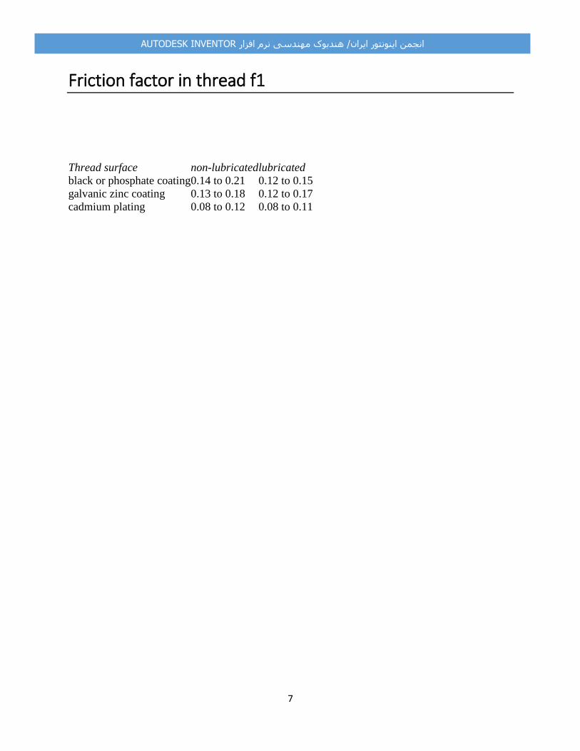
Friction factor in thread f1
Thread surface non-lubricated lubricated
black or phosphate coating 0.14 to 0.21 0.12 to 0.15
galvanic zinc coating 0.13 to 0.18 0.12 to 0.17
cadmium plating 0.08 to 0.12 0.08 to 0.11

8
AUTODESK INVENTORانجمن اینونتور ایران/ هندبوک مهندسی نرم افزار
Force input factor n
Examples of force loading
where: L F ... width of the material loaded by the operation force

9
AUTODESK INVENTORانجمن اینونتور ایران/ هندبوک مهندسی نرم افزار
Allowable pressure in threads
Allowable pressure in threads of connection bolts.
Nut material
Strength class of bolt material according to the CSN and ISO standards
4A 4D 4S 5D 5S 6S 6G 8G, 8E 10K, 10G 12K
3.6 4.6 4.8 5.6 5.8 6.8 6.9 8.8 10.9 12.9
pA [MPa]
steel 40 50 75 70 90 110 120 150 200 250K
gray cast iron 25 30 45 40 55 70 80 90 125 150
light alloys 18 20 30 27 35 45 50 60 80 90

10
AUTODESK INVENTORانجمن اینونتور ایران/ هندبوک مهندسی نرم افزار
Fatigue strength of bolted connection
Conventional check procedures at fatigue loaded bolted connection (based on the ultimate or
yield strength of material) do not provide sufficient guaranty of safe joint design. Consequently,
the fatigue strength of joint is used in check of fatigue loaded joints. The description of fatigue
loaded bolted connection joints checking follows. This description follows step by step the
implementation in the program:
1. Specifying an endurance limit
In the first step the calculation determines the endurance limit at constant strength σ C for the
specified type, design, loading, and material of bolted connection.
2. Specifying finite-life fatigue limit
The finite-life fatigue limit σ f is calculated for the specified joint life that is in the (N< 10 6
cycles) range of timed strength. Calculation continues with this finite-life fatigue limit.
3. Calculation of parameters of particular fatigue loadings
Mean values for given upper and lower cycle loadings are calculated their mean values according
to the following formulas. It is done for all specified loadings.
4. Effect of strokes
If strokes affect the joint besides the fatigue loading, their influence must be included into the
calculation. This is implemented by using the dynamic stroke factor in the formula for
determining the maximum calculated loading:
F max = F m + η F a
5. Calculation of actuating stress in the bolted connection joint
Mean cycle stress σ m and upper cycle stress σ h are calculated for the specified mean cycle
loading F m and maximum calculated loading F max with the formulas used in static calculation.
These stresses are used for calculation of cycle amplitude according to the formula:

11
AUTODESK INVENTORانجمن اینونتور ایران/ هندبوک مهندسی نرم افزار
σ a = σ h - σ m
6. Specifying fatigue strength of joint
For calculated stress and known endurance limit, the resulting strength of fatigue joint is easily
determined according to the selected fatigue curve. The procedure of fatigue strength
determination for both normal and shear stresses is obvious from the following pictures.
Haigh charts of normal stress for different σ a / σ m ratio (modified Godman fatigue curve is used):
Haigh charts of normal stress for different τ a / τ m ratio (modified Godman fatigue curve is used):
7. Joint check
In the last step, the program calculates the joint safety factor n C = σ A / σ a and compares it with
the required safety degree. For convenient bolted connection the condition n f ≤ n C must be
satisfied.

12
AUTODESK INVENTORانجمن اینونتور ایران/ هندبوک مهندسی نرم افزار
Bolted connection endurance limit determination
Corrected endurance limit at the constant strength σ e of the bolted connection is determined for
the selected type, design, material, and joint loading from the formula:
σ e = σ' e k e k f [MPa, psi]
where:
σ' e basic endurance limit of a test bar from the selected material [MPa, psi]
k e modified factor of stress concentration [-]
k f factor of miscellaneous effects [-]
1. Basic endurance limit σ' e
If you do not have available results of material tests of the selected bolted connection material
and do not know the exact value of basic endurance limit, its value can be estimated by the
program. In this case, the calculation designs the basic endurance limit according to the reversed
traction - pressure formula:
σ' e ≈ 0.4 S U - for reversed traction - pressure
S u ultimate tensile strength [MPa, psi]
2. Modified factor of stress concentration k e
High local stress concentrations originate in a joint when the bolted connection is fatigue loaded
because of bolted connection notch effect. These concentrations considerably reduce the joint
fatigue strength. Modified factor of stress concentration is determined from the ke = 1/K
formula, where the fatigue-strength reduction factor K depends on the bolted connection type,
shape, design, bolted connection quality, and the bolted connection loading.
3. Factor of miscellaneous effects k f
All other effects that can reduce or increase the fatigue strength of bolted connection (the
influence of corrosion, for example) are included in this factor.

13
AUTODESK INVENTORانجمن اینونتور ایران/ هندبوک مهندسی نرم افزار
afety factor of fatigue loaded bolted connection
The required minimum safety factor of bolted connection during fatigue loading nf represents a
ratio of fatigue loading and the calculated stress of bolted connection, that is, n f ≤σ A / σ a or n f ≤τ
A / τ a .
The recommended minimum value of safety factor at fatigue loading is indicated in the n f =
<1.5...3> range and it depends on the fatigue loading pattern. In general, the reversed loading is
less favorable than fluctuating loading when the fatigue loading of bolted connection is
considered.
The following picture displays the effect of loading course to bolted connection safety. The
range of recommended minimum values of safety factor, which depends on the value of cycle
asymmetry factor r = σ n / σ h , is hatched.
14
AUTODESK INVENTORانجمن اینونتور ایران/ هندبوک مهندسی نرم افزار
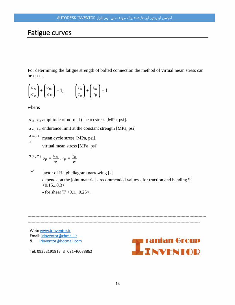
Fatigue curves
For determining the fatigue strength of bolted connection the method of virtual mean stress can
be used.
where:
σ a , τ a amplitude of normal (shear) stress [MPa, psi].
σ e , τ e endurance limit at the constant strength [MPa, psi]
σ m , τ
m mean cycle stress [MPa, psi].
σ F , τ F
virtual mean stress [MPa, psi]
Ψ factor of Haigh diagram narrowing [-]
depends on the joint material - recommended values - for traction and bending Ψ
<0.15...0.3> - for shear Ψ <0.1...0.25>.
------------------------------------------------------------------------------------------------------------------------------------------
-------------------------------------------------------------------------------------------------------------------------------------
Web: www.irinventor.ir Email: [email protected] & [email protected] Tel: 09352191813 & 021-46088862

15
AUTODESK INVENTORانجمن اینونتور ایران/ هندبوک مهندسی نرم افزار
![Bolted Connections[1]](https://static.fdocuments.in/doc/165x107/54e7f8c84a7959704f8b46b8/bolted-connections1.jpg)