IR868LR & IRUS915LR Infrared sensor Programming manual
52
FC0000-2-15-PIR_LoRa-00-DO-2.0 IR868LR & IRUS915LR programming manual PROGRAMMING MANUAL LoRaWAN™ SENSOR SERIES Revision 1.0 – Jun 2017 ©2017 ASCOEL S.r.l. Page 1 of 52 www.ascoel.it IR868LR & IRUS915LR Infrared sensor Programming manual
Transcript of IR868LR & IRUS915LR Infrared sensor Programming manual

FC0000-2-15-PIR_LoRa-00-DO-2.0
IR868LR & IRUS915LR programming manual
PROGRAMMING MANUAL LoRaWAN™ SENSOR SERIES
Revision 1.0 – Jun 2017 ©2017 ASCOEL S.r.l. Page 1 of 52 www.ascoel.it
IR868LR & IRUS915LR Infrared sensor
Programming manual

FC0000-2-15-PIR_LoRa-00-DO-2.0
IR868LR & IRUS915LR programming manual
PROGRAMMING MANUAL LoRaWAN™ SENSOR SERIES
Revision 1.0 – Jun 2017 ©2017 ASCOEL S.r.l. Page 2 of 52 www.ascoel.it
1 Sommario 2 Introduction 6
3 Installation 7
3.1 Sensor fixing 8
3.1.1 Installation without the mount bracket: 8
3.1.2 Installation with the mount bracket: 8
3.2 What to do and what don't to do 9
3.3 Battery replacement 10
4 How the sensor works 11
4.1 Confirmed an unconfirmed messages 11
4.2 Alive 11
4.3 MODE of operation 12
4.3.1 MODE 1 12
4.3.2 MODE 2 12
4.3.3 MODE 3 13
4.3.4 MODE 4 14
4.4 Transmitted information 15
4.4.1 Event flag status 15
4.4.2 Detection counter number 15
4.5 Device configuration flag 16
4.6 MODE configuration flag 17
5 Technical specification 18
6 Payload 19
6.1 Overview 19
6.2 Uplink message specification 21
6.2.1 Message on port 2. Last downlink sequence number received 21
6.2.2 Message on port 5. Presentation 21
6.2.3 Message on port 6. Serial Number 21
6.2.4 Message on port 7. FW release, library release, HW release 21
6.2.5 Message on port 8. Battery level 22
6.2.6 Message on port 9. Alive 22
6.3 Transmitted information 22
6.3.1 Message on port 10. Ack / Nack 23
6.3.2 Message on port 20. Alarm event 24
6.4 Downlink message specification 25
6.4.1 Message on port 2. Enquiry last downlink sequence number 25
6.4.2 Message on port 5. Enquiry model 26
6.4.3 Message on port 6. Enquiry Serial number of device 26
6.4.4 Message on port 7. Enquiry Firmware release, LoraWAN Lib release, HW revision 27
6.4.5 Message on port 8. Enquiry Battery level 28
6.4.6 Message on port 9. ALIVE setting interval value 28
6.4.7 Message on port 13. Device configuration flags 29
FC0000-2-15-PIR_LoRa-00-DO-2.0
IR868LR & IRUS915LR programming manual
PROGRAMMING MANUAL LoRaWAN™ SENSOR SERIES
Revision 1.0 – Jun 2017 ©2017 ASCOEL S.r.l. Page 3 of 52 www.ascoel.it
7 Uart Interface 30
8 Command Syntax 30
8.1 Command organization 30
9 Shell access level 31
10 General Command 31
11 MAC Command 32
11.1 DevEui Command 32
11.2 Devaddr Command 33
11.3 Appeui Command 33
11.4 NwkSkey Command 34
11.5 AppSkey Command 34
11.6 Appkey Command 35
11.7 Pwridx Command (in current FW revision this command is disabled) 35
11.8 Dr Command (in current FW revision this command is disabled) 36
11.9 Adr Command 36
11.10 Confirmed/unconfirmed port Command 37
11.11 Retry Command 38
11.12 Link Check Command 38
11.13 Rx delay1 Command 39
11.14 Rx2 frequency Command 39
11.15 Rx2 data rate Command 40
11.16 Duty cycle Command 41
11.17 OTAA Command 42
11.18 Class Command 42
11.19 Password Command 43
11.20 Default Command 44
11.21 Save Command 44
11.22 Reboot Command 44
11.23 Info Command 44
12 IR868LR specific shell command (DEV) 45
12.1 Alive interval Command 45
12.2 Device Flag Command 46
12.3 PIR sensor inhibition 46
12.4 MODE 1 47
12.5 MODE 2 47
12.6 MODE 3 47
12.7 MODE 4 48
12.8 Mode Command (get only) 49
12.9 Model Command (get only) 50
12.10 Production date Command (get only) 50
12.11 Serial number Command (get only) 50
12.12 Battery level Command (get only) 51

FC0000-2-15-PIR_LoRa-00-DO-2.0
IR868LR & IRUS915LR programming manual
PROGRAMMING MANUAL LoRaWAN™ SENSOR SERIES
Revision 1.0 – Jun 2017 ©2017 ASCOEL S.r.l. Page 4 of 52 www.ascoel.it

FC0000-2-15-PIR_LoRa-00-DO-2.0
IR868LR & IRUS915LR programming manual
PROGRAMMING MANUAL LoRaWAN™ SENSOR SERIES
Revision 1.0 – Jun 2017 ©2017 ASCOEL S.r.l. Page 5 of 52 www.ascoel.it
Document revision
Doc. Rev. FW rev Author Note / remarks Date
2.0 1.0.3 R&D laboratory GM Document created. First issue Jun, 2017

FC0000-2-15-PIR_LoRa-00-DO-2.0
IR868LR & IRUS915LR programming manual
PROGRAMMING MANUAL LoRaWAN™ SENSOR SERIES
Revision 1.0 – Jun 2017 ©2017 ASCOEL S.r.l. Page 6 of 52 www.ascoel.it
2 Introduction The IR868LR family is an infrared passive sensor for indoor application.
All objects with a temperature above absolute zero emit heat in the form of radiation. Usually this radiation
is not visible to the human eye it radiates at infrared wavelengths, but electronic devices designed for such
a purpose can detect it.
The term passive in this instance refers to the fact that PIR devices do not generate or radiate any energy
for detection purposes. They work entirely by detecting the energy given off by other objects.
PIR sensors don't detect or measure "heat"; instead they detect the infrared radiation emitted or reflected
from an object.
The PIR sensor integrates a dual element pyroelectric detector for the detection of body heat in order to
activate the alarm in case of intrusion. The sensor is suitable for apartments, offices, shops, buildings in
general this thanks to the possibility to adjust its sensitivity, even for small areas such as motor homes. It
has been designed to fit perfectly with any environment, aesthetically pleasing, compact and remarkably
robust.
The use of digital technology obtained by the use of the microcontroller, coupled to the Fresnel optics it
provides good accuracy in detecting (37 beams spread over 3 horizontal levels), immunity false alarms
and high reliability without reducing the sensitivity of the IR868LR.
The device is protected against tampering of the container; in case of tampering it transmits the code that
identifies this type of event.
It has a variable coverage from 8 to 20 meters adjustable with a trimmer with an aperture of 100° to adapt
to installation requirements and it has a temperature compensation and a white light filter to minimize false
alarms.
Of considerable importance is the low power consumption in stand-by mode that allows obtaining a
remarkable battery life, minimizing its replacement during operation.
Furthermore, the joint allows to easily obtaining the right inclination in order to cover optimally the desired
area.
IR868LR family is equipped with the radio module ACL868x that allows the device to connect to public or
private networks that support the protocol LoRaWAN 1.0.1
PIR sensor is configured as a node of class A
This wireless motion sensor includes the following features:
16mt coverage area
(37 beams on 3 horizontal planes, opening 100 °)
Adjustable sensitivity detection level
Adjustable inhibition time.
Default four minutes transmitter lockout time after an
alarm that helps to extend battery life
Cover-activated tamper
Supervisory signals transmitted every 50 minutes
(default value, it can be modified) to the receiver
system (ALIVE signal)
Sensor reports Low battery level (trouble) to the
receiver system
Buzzer for low battery indication
LoRaWAN 1.0.1 compliant radio module
Three beams
Three beams feature

FC0000-2-15-PIR_LoRa-00-DO-2.0
IR868LR & IRUS915LR programming manual
PROGRAMMING MANUAL LoRaWAN™ SENSOR SERIES
Revision 1.0 – Jun 2017 ©2017 ASCOEL S.r.l. Page 7 of 52 www.ascoel.it
3 Installation For obtain the maximum performance is mandatory follow few guidelines in installation procedures. Because the sensor is based on passive infrared element detector, the key factor is carry on the PIR
element the max level of infrared radiation. This is performed by the fresnel lens that focalize the IR on
pyroelectric device.
The next figure show as the lens focalize the IR on PIR element; the measure is performed with the sensor fixed at 2,1 meter height and perpendicular to the floor, or tilted by 6 degree with an special mount bracket.
Fig. 2 (sensor tilted down to 6 degrees)
Fig. 3 (sensor mounted perpendicular to the floor)

FC0000-2-15-PIR_LoRa-00-DO-2.0
IR868LR & IRUS915LR programming manual
PROGRAMMING MANUAL LoRaWAN™ SENSOR SERIES
Revision 1.0 – Jun 2017 ©2017 ASCOEL S.r.l. Page 8 of 52 www.ascoel.it
3.1 Sensor fixing
3.1.1 Installation without the mount bracket:
• Remove the front cover and then the card by pulling back the plastic
clip (M see Fig. 1 Bottom of the container).
• If necessary, hack the pre-printed holes in the box bottom, then drill
holes
• 6 mm fixing in the wall, and fasten the plastic bottom oriented with
the rounded part toward the
floor to a height of 210 cm.
• Replace the card with the battery and then secure the cover
previously removed.
3.1.2 Installation with the mount bracket:
• Fix the mount bracket at the bottom of the container using the two
self-tapping screws.
• Fix the mount bracket to the wall at a height of 210 cm from the floor
and then orient the sensor in
appropriate direction to cover the affected area, while maintaining
the sensor perpendicular to the floor or inclined towards the floor by
about 6 ° degree
• Fit the batteries and reassemble the cover.
Please remember that mount bracket is optional accessories and must be ordered separately.
Fig. 1 Bottom of the container

FC0000-2-15-PIR_LoRa-00-DO-2.0
IR868LR & IRUS915LR programming manual
PROGRAMMING MANUAL LoRaWAN™ SENSOR SERIES
Revision 1.0 – Jun 2017 ©2017 ASCOEL S.r.l. Page 9 of 52 www.ascoel.it
3.2 What to do and what don't to do
For proper installation and in order to avoid false alarms it is necessary to follow some rules for the sensor
positioning:
• Position the sensor on stable and non-vibrated surfaces
• Do not install near sources of heat or sunlight
• Do not install near air currents
• Do not install near electrical wiring
• Do not run toward glass walls
• Windows should be closed in any area which has an armed motion sensor
• Position the sensor to protect an area where an intruder would be most likely to walk across the
detection pattern
• Mount the sensor permanently on a flat wall or in a corner. Do not set it on a shelf.
FC0000-2-15-PIR_LoRa-00-DO-2.0
IR868LR & IRUS915LR programming manual
PROGRAMMING MANUAL LoRaWAN™ SENSOR SERIES
Revision 1.0 – Jun 2017 ©2017 ASCOEL S.r.l. Page 10 of 52 www.ascoel.it
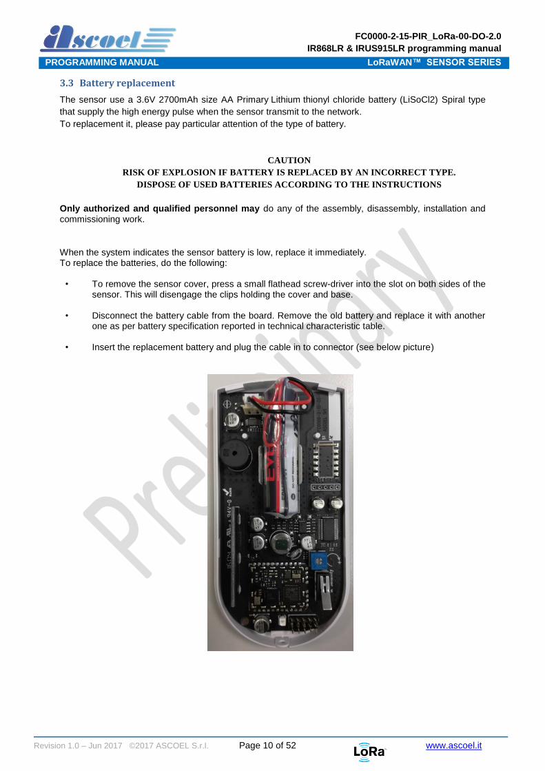
3.3 Battery replacement
The sensor use a 3.6V 2700mAh size AA Primary Lithium thionyl chloride battery (LiSoCl2) Spiral type
that supply the high energy pulse when the sensor transmit to the network.
To replacement it, please pay particular attention of the type of battery.
CAUTION
RISK OF EXPLOSION IF BATTERY IS REPLACED BY AN INCORRECT TYPE.
DISPOSE OF USED BATTERIES ACCORDING TO THE INSTRUCTIONS
Only authorized and qualified personnel may do any of the assembly, disassembly, installation and commissioning work.
When the system indicates the sensor battery is low, replace it immediately. To replace the batteries, do the following:
• To remove the sensor cover, press a small flathead screw-driver into the slot on both sides of the sensor. This will disengage the clips holding the cover and base.
• Disconnect the battery cable from the board. Remove the old battery and replace it with another one as per battery specification reported in technical characteristic table.
• Insert the replacement battery and plug the cable in to connector (see below picture)

FC0000-2-15-PIR_LoRa-00-DO-2.0
IR868LR & IRUS915LR programming manual
PROGRAMMING MANUAL LoRaWAN™ SENSOR SERIES
Revision 1.0 – Jun 2017 ©2017 ASCOEL S.r.l. Page 11 of 52 www.ascoel.it
4 How the sensor works
The IR868LR family is developed for indoor use only and can be operating in several mode for meet several
scenario request.
At the start-up time two message are transmits spontaneously for inform the server that sensor is power
on:
The first message is a string that representing the sensor model
(see chapter 6.2.2 Message on port 5. Presentation pag.21)
The second message is a string that report the version of the firmware, library and hardware
(see chapter 6.2.4 Message on port 7. FW release, library release, HW release pag.21)
4.1 Confirmed an unconfirmed messages
The LoRaWAN protocol permits to send to the network server, messages of type confirmed or
unconfirmed.
The difference is that unconfirmed messages are transmit one time only, and the sensor do not wait for
any type of response from the server. The unconfirmed messages are preferred type for information that
not have particular critical issues because is not guaranteed that messages are delivered to the destination.
Example of unconfirmed messages are ALIVE, LOW BATTERY and response from server Enquiry.
Differently, the confirmed messages are transmit several time (from 1 to 8 programmable) and the sensor
wait to receive an acknowledge by the server.
The confirmed type messages are preferred for alarm event where the chance that message is not
delivered is not permitted.
The programming of which messages are confirmed or not, is based on port.
Only by the shell in local mode is possible set which ports are confirmed type, with the appropriate
command.
Is possible set up to 10 ports there are treated as confirmed type.
4.2 Alive
For get a periodic signal from the sensor, is available the ALIVE concept.
The ALIVE is a periodic message transmit to the server for inform it that sensor is operating correctly, this
packet is transmitted on port 9 (see chapter 6.2.6 Message on port 9. Alive pag.22)
FC0000-2-15-PIR_LoRa-00-DO-2.0
IR868LR & IRUS915LR programming manual
PROGRAMMING MANUAL LoRaWAN™ SENSOR SERIES
Revision 1.0 – Jun 2017 ©2017 ASCOEL S.r.l. Page 12 of 52 www.ascoel.it
4.3 MODE of operation
The scenario where the sensor operate is called MODE and in this firmware revision four MODE are
available.
4.3.1 MODE 1
This is the basic function mode where PIR sensor act as a typical Passive Infrared Sensor for burglar
alarm.
When an intrusion is detected, the sensor send an immediate uplink message to the server reporting the
alarm event.
Due to the nature of this type of function, the message of the return in the idle state is not transmit to the
server (see the chapter MODE configuration flag4.4.1 Event flag pag.15)
When an intrusion transmission is performed, the sensor observe a period of transmit suspension called
“PIR inhibit time”. This period is programmable from the server or via serial shell, between 20 and 600
seconds.
This behavior is necessary because if the sensor is installed in place with a high tax of walking people, at
every detection will be generate a transmission to the network causing a consumption of battery energy
and an abnormal occupancy of the radio network.
No other setup flag is needed if this mode is programmed.
4.3.2 MODE 2
With this mode, the PIR can work as a counter.
PIR sensor will send message only when a specific number of detection is reached, this counter is called
Detection Counter Number.
You can set from the server or via serial shell, a specific Detection Counter Number including between
1 and 65535.
PIR sensors will deliver an uplink message to server only when the Detection Counter Number you set
is reach.
If desired, is possible reset the Detection Counter Number every time the transmission is performed.
If the Detection Counter Number is not reset, a total amount of detection counter is reported to the server.
For set this function refer to the chapter MODE configuration flag4.6 MODE configuration flag pag. 17
In MODE2 the “PIR inhibit time” delay is not applicable.
Example:
Detection Counter Number set to 15.
PIR will deliver an uplink message to server only when the detection of movement reach 15 counts.
It is totally independent by time: based on application and installation you can get this message in a
frequent time or also at several days distance.
For example PIR installed in a corridor with huge number of people passage during the day hours but no
passage in the night hours, PIR will deliver the message during the day time very frequency while during
the night hours PIR will not send any message.
At every detection, a fast blinking of led can be observed.
FC0000-2-15-PIR_LoRa-00-DO-2.0
IR868LR & IRUS915LR programming manual
PROGRAMMING MANUAL LoRaWAN™ SENSOR SERIES
Revision 1.0 – Jun 2017 ©2017 ASCOEL S.r.l. Page 13 of 52 www.ascoel.it
4.3.3 MODE 3
With this mode, the sensor send messages at regular intervals called Periodic Interval Time as
programmed from the server or via serial shell.
The Periodic Interval Time expressed in seconds, must be including between 15 and 864000 seconds
(10 days).
The PIR will deliver to the server an uplink message with the Detection Counter Number collected from
the sensor, when the specific interval time is elapsed.
If desired, is possible reset the Detection Counter Number every time the transmission is performed.
If the Detection Counter Number is not reset, a total amount of detection counter is reported to the
server.
For set this function refer to the chapter MODE configuration flag4.6 MODE configuration flag pag. 17
Another feature that you have available, is the possibility of transmit a message when a programmed
Detection Counter Number is reached, before the Periodic Interval Time is elapsed.
For do this, you set the appropriate flag in to the chapter MODE configuration flag4.6 MODE configuration
flag pag. 17
In MODE3 the “PIR inhibit time” delay is not applicable.
Example:
Periodic Interval Time set to 10 minutes
Detection Counter Number set to 15
Sensor PIR will deliver a message to server every 10 minutes reporting the Detection Counter Number
happened in this period of time.
Sensor will deliver to server a message reporting that the Detection Counter Number is 15 if this count
is reach before the Periodic Interval Time of 10 minutes is elapsed, and if enable flag is set (see the
chapter MODE configuration flag4.6 MODE configuration flag pag. 17)
At every detection, a fast blinking of led can be observed.
FC0000-2-15-PIR_LoRa-00-DO-2.0
IR868LR & IRUS915LR programming manual
PROGRAMMING MANUAL LoRaWAN™ SENSOR SERIES
Revision 1.0 – Jun 2017 ©2017 ASCOEL S.r.l. Page 14 of 52 www.ascoel.it
4.3.4 MODE 4
This mode was developed for working as a room or desk occupancy sensor.
You need to set a temporal interval called guard time, that must be including between from 30 and 7200
seconds (2 hours)
The guard time is the period that the sensor must be not detect movement in own field of view, for indicate
that room is empty.
Note that if the guard time is abnormally high, when the room is leaved from the last occupant, the sensor
will reporting the server the room empty message when guard time the is elapsed.
At the time=0, sensor will consider the space as empty. As soon as a movement is detected, PIR will send
a message to server for indicate that the room is occupied.
In that moment, PIR will activate the guard time and will start the countdown.
If during the guard time, the sensor will detect a new movement, the guard time will re-start the countdown
from the beginning. If during the guard time PIR will not detect any movement, PIR will deliver a new
message to server for indicate that the room is now empty.
In this mode, the sensor send the information as state and not as event as per mode 1.
In MODE4 the “PIR inhibit time” delay is not applicable.
At every detection, a fast blinking of led can be observed.
Example:
guard time set to 900 (15 minutes)
At the first detection, the sensor will deliver a message to server for indicate that the room is occupied
setting the bit 0 in the event flag (see the chapter MODE configuration flag4.4.1 Event flag pag.15)
At the same time, guard time will be activated and it will start the countdown.
If in these 15 minutes of guard time, the sensor PIR will detect new movements, guard time will restart
the countdown.
As soon as for 15 minutes (guard time set) sensor PIR will not detect any movement, a new message will
be sent to server for indicate the fact that now room is empty, clearing the bit 0 in the event flag (see the
chapter MODE configuration flag 4.4.1 Event flag pag.15)
If you have a room occupied for 2 hours, PIR will send 2 messages: first one at time 0 when the first people
got in the room, second one after 2 hours and 15 minutes after latest people left the room.
In this mode, you can also set a parameter called repetition time that ask to the PIR sensor to send
message at a specific interval you set where it will tell you that room is still occupied.
This time can be set from minimum 20 seconds up to maximum value minor then guard time.
You can choose if you want to have this repetition, function set or not. (see chapter MODE configuration
flag 54.6 MODE configuration flag pag. 17)
Looking at above example, if you activate also repetition time at 10 minutes, in the 2 hours of room
occupancy you will get:
First message as soon as the first people got in the room.
A message every 10 minutes that tell you that room is still occupied
A latest message after 2hrs and 15 minutes that tell you that the room is now free.
Be aware that repetition time send an uplink message to server and if it is set with short time it can reduce
battery life time and don’t respect the 1% duty cycle of LoRaWAN protocol.

FC0000-2-15-PIR_LoRa-00-DO-2.0
IR868LR & IRUS915LR programming manual
PROGRAMMING MANUAL LoRaWAN™ SENSOR SERIES
Revision 1.0 – Jun 2017 ©2017 ASCOEL S.r.l. Page 15 of 52 www.ascoel.it
4.4 Transmitted information
4.4.1 Event flag status
This byte is a mask bit flag that report the status of the sensor and is transmitted in several port and in
various scenario.
Event Flag byte
MSB 7 6 5 4 3 2 1 0 LSB
Bit value 0 0 0 0 0 x x x
[7:3] reserved
[2] Battery status
1 = low battery (below 25%)
0 = battery OK
[1] Tamper
1 = Tamper alarm
0 = No Tamper alarm
[0] Intrusion Alarm detected
1 = Intrusion alarm detected
0 = No Intrusion alarm detected
4.4.2 Detection counter number
This unsigned word (16 bits) report the number of the detection of the PIR sensor.
Detection counter number
MSB 15 14 13 12 11 10 9 8 LSB
Bit value 0 0 0 0 0 0 0 0
MSB 7 6 5 4 3 2 1 0 LSB
Bit value 0 0 0 0 0 0 0 0
[15:0] Number of detection
FC0000-2-15-PIR_LoRa-00-DO-2.0
IR868LR & IRUS915LR programming manual
PROGRAMMING MANUAL LoRaWAN™ SENSOR SERIES
Revision 1.0 – Jun 2017 ©2017 ASCOEL S.r.l. Page 16 of 52 www.ascoel.it
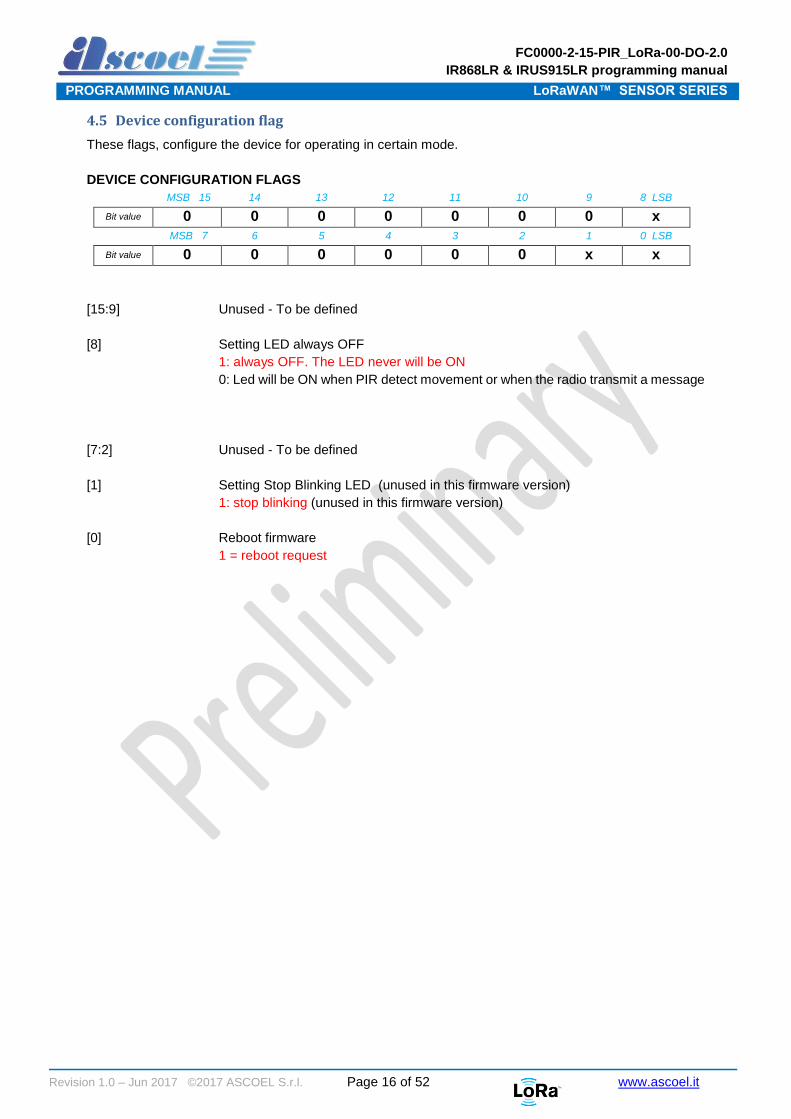
4.5 Device configuration flag
These flags, configure the device for operating in certain mode.
DEVICE CONFIGURATION FLAGS
MSB 15 14 13 12 11 10 9 8 LSB
Bit value 0 0 0 0 0 0 0 x
MSB 7 6 5 4 3 2 1 0 LSB
Bit value 0 0 0 0 0 0 x x
[15:9] Unused - To be defined
[8] Setting LED always OFF
1: always OFF. The LED never will be ON
0: Led will be ON when PIR detect movement or when the radio transmit a message
[7:2] Unused - To be defined
[1] Setting Stop Blinking LED (unused in this firmware version)
1: stop blinking (unused in this firmware version)
[0] Reboot firmware
1 = reboot request

FC0000-2-15-PIR_LoRa-00-DO-2.0
IR868LR & IRUS915LR programming manual
PROGRAMMING MANUAL LoRaWAN™ SENSOR SERIES
Revision 1.0 – Jun 2017 ©2017 ASCOEL S.r.l. Page 17 of 52 www.ascoel.it
4.6 MODE configuration flag
All the MODE, have associated some flags that configure the behaviour of function.
MODE configuration Flag
MSB 15 14 13 12 11 10 9 8 LSB
Bit value 0 0 0 0 0 0 0 0
MSB 7 6 5 4 3 2 1 0 LSB
Bit value 0 0 0 0 x x x x
[15:4] Unused
To be defined
[3] Transmit ‘room busy’ periodically at the repetition time interval (only for MODE 4)
1 = send a ‘Room occupied’ message periodically
0 = DO NOT sent (defaut value)
[2] TBD
1 = TBD
0 = TBD
[1] Transmit if Detection Counter Number if reached before Periodic Interval Time
is elapsed (only for MODE 3)
1 = send Detection Counter Number is reached
0 = send only if Periodic Interval Time is elapsed (default value)
[0] Detection Counter Number reset (MODE 2 and MODE 3)
1 = reset request
0 = Not reset (default value)

FC0000-2-15-PIR_LoRa-00-DO-2.0
IR868LR & IRUS915LR programming manual
PROGRAMMING MANUAL LoRaWAN™ SENSOR SERIES
Revision 1.0 – Jun 2017 ©2017 ASCOEL S.r.l. Page 18 of 52 www.ascoel.it
5 Technical specification
Specifications
Parameters Min Typ Max unit
Frequency band IR868LR - 867.1 < f < 868.5 - MHz.
IRUS915LR - 902 < f < 928 - MHz
RF power (EU868) 2 - 14 dBm EIRP
RF power (EN915) 2 18 dBm EIRP
Modulation LoRa ™
Protocol LoRaWan 1.0.1 Class A
RX sensivity -138 dBm
Battery 1pz AA 3.6V lithium-thionyl 2700mA
By EVE P/N ER14505V
Temperature range -20 +25 +55 °C
Antenna - PCB printed -
Power supply 2.8 3 3.6 Vdc
Consumption standby 13 15 17 uA
Consumption TX IR868LR 40 45 55 mA
Consumption TX IRUS915LR 60 70 80 mA
Alarm inhibit time 5 240 (default) 600 s
Dimension 120 x 60 x 45 mm
Reference standards EN 60950-1:2006 + A11:2009 + A1:2010 +
A12:2011 -
EN 62311:2008
EN 301 489-1 V1.9.2
EN 301 489-3 V1.6.1; Part 3
EN 300 220 V2.4.1

FC0000-2-15-PIR_LoRa-00-DO-2.0
IR868LR & IRUS915LR programming manual
PROGRAMMING MANUAL LoRaWAN™ SENSOR SERIES
Revision 1.0 – Jun 2017 ©2017 ASCOEL S.r.l. Page 19 of 52 www.ascoel.it
6 Payload
6.1 Overview
All the messages exchanged between sensors and server are reduced to the strictly necessary for
transport of the information requested. No other types of protocols are used for transport the information
on top the LoRaWAN protocol; this one is all the needed for ensure the correct relay of information.
All message are transmitted in RAW format.
The maximum length of any messages in uplink direction is limited to 11 bytes. This precautions is
necessary for don’t trespassing the maximum length of 11 bytes in US915 band at DR0.
The message from sensor node to the server (uplink direction) don’t expected any type of control how
message length, checksum or any other type of error correction.
The messages from server to the sensor node (downlink direction) are completed with length and
checksum control. This precaution is necessary for avoid that wrong messages transmitted from the server
may put the sensors in unpredictable state.
The messages received from the sensors, are confirmed to the server by sending ACK to inform him of
the correct receipt, or NACK in case of corrupted message. If nothing message is received from sensor,
this one no respond anything.
The information that the sensor is able to transmit, are organized on several port number.
This mechanism is used both for uplink that downlink messages.

FC0000-2-15-PIR_LoRa-00-DO-2.0
IR868LR & IRUS915LR programming manual
PROGRAMMING MANUAL LoRaWAN™ SENSOR SERIES
Revision 1.0 – Jun 2017 ©2017 ASCOEL S.r.l. Page 20 of 52 www.ascoel.it
Uplink message list:
Downlink message list:
From sensor to server (uplink)
Port # Example Payload raw (example)
Last sequence downlink 2 15 0000000F
Presentation 5 IR868LR 49523836384C52
Serial Number 6 Serial number of device AA112233445566FF
FW release, library release, HW release
7 Firmware release 1.11.2639 LoRaWan stack Release 4.3.15 Hardware release B
010B0A4F04030F42
Battery level 8 Level in percentage, 94% 5E
Alive 9 Level in percentage, 94% Event flag (tamper alarm)
5E02
ACK 10 Ack on port 9 41636b09
Event + counter 20 Event flag, number of detection counter (flag tamper+PIR) and 15 detection
03000F
From server to sensor (Downlink)
Port # From server Example Payload raw
Response from the sensor
Request last downlink counter sequence number
2 Enq 05456E715F The last SEQDN received
Request sensor model
5 Enq 05456E715F CM868LRCB
Request Serial Number
6 Enq 05456E715F Serial number
Request FW, lib & HW release
7 Enq 05456E715F Fw, lib & HW revision
Request Battery level 8 Enq 05456E715F Battery level in percentage
Alive interval setting 9 Set the alive interval to 2 hours (7200 seconds)
041C2038 Ack or Nack
PIR Inhibit time 11 Set the inhibition time for the PIR sensor
0400F0F4 Ack or Nack
Mode settings 12 Set the scenario Ack or Nack
Flag parameters settings 13 Set various flags 040F0803 Ack or Nack

FC0000-2-15-PIR_LoRa-00-DO-2.0
IR868LR & IRUS915LR programming manual
PROGRAMMING MANUAL LoRaWAN™ SENSOR SERIES
Revision 1.0 – Jun 2017 ©2017 ASCOEL S.r.l. Page 21 of 52 www.ascoel.it
6.2 Uplink message specification
In this chapter will be analyzed in detail the message transmit in specific port.
6.2.1 Message on port 2. Last downlink sequence number received
This message is basically a service message and report to the server the last downlink counter value
received from the sensor.
The downlink counter is part of authentication mechanism of LoRaWAN protocol and avoid that the
previously message can be reproduced and retransmit from the server to sensor in a typically man-in-the
middle attach.
If a duplicated downlink counter is received, a transmission on port 2 is generated with the current downlink
counter number. If the server is able to rebuild the message with the next counter number, the sensor will
accept the message.
The Last Downlink number message is provided also if the server send an “Enq” on port 2.
(ref. chapter 6.4.1)
6.2.2 Message on port 5. Presentation
The payload contains the sensor model string in ASCII format.
For this specific sensor, the string IR868LR is transmitted in HEX format 49523836384C52
The presentation message is sent ONLY every times the sensor performs a reboot.
The reboot is caused by power-on reset or by a server command.
The presentation message is provided also if the server send an “Enq” on port 5. (ref. chapter 6.4.2)
6.2.3 Message on port 6. Serial Number
The payload contains the serial number string in Hexadecimal format. 8 bytes length (e.g.
AA112233445566FF)
The Serial Number message is provided ONLY if the server send an “Enq” on port 6. (ref. chapter 6.4.3)
6.2.4 Message on port 7. FW release, library release, HW release
The payload contains the firmware release, the LoRaWAN Stack release and the Hardware revision.
This information is provided at the start-up of the sensor, and if the server send an “Enq” on port 7. (ref.
chapter 6.4.4)
The fields are not divided by separator char.
An example of message is: 010B0A4F04030F42
Where:
Value HEX Description width range meaning
01 Major release 1 byte Binary from 0 to 0xFF Hex Firmware release 1.11.2639
0B Minor release 1 byte Binary from 0 to 0xFF Hex
0A 4F Build 2 byte Binary from 0 to 0xFFFF Hex
04 Major rel. of LoRaWAN stack 1 byte Binary from 0 to 0xFF Hex LoRaWAN stack release 4.3.15
03 Minor rel. of LoRaWAN stack 1 byte Binary from 0 to 0xFF Hex
0F Build rel. of LoRaWAN stack 1 byte Binary from 0 to 0xFF Hex
42 Hardware revision 1 byte ASCII Format from A to Z HW rel. B

FC0000-2-15-PIR_LoRa-00-DO-2.0
IR868LR & IRUS915LR programming manual
PROGRAMMING MANUAL LoRaWAN™ SENSOR SERIES
Revision 1.0 – Jun 2017 ©2017 ASCOEL S.r.l. Page 22 of 52 www.ascoel.it
6.2.5 Message on port 8. Battery level
The payload contains the battery charge percentage level.
The battery Level message is sent spontaneously on port 8 if the battery charging level is below 25% or if
the server send an “Enq” on port 8. (ref. chapter 6.4.56.4.2)
This message is automatically repeated every 6 hours when the battery is below the 25% of charge
level.
An example of message is: 5E
Where:
Value HEX Description width range meaning
5E Percentage of battery charge 1 byte Binary from 0 to 0x64 hexadecimal Level battery from 0% to 100%
6.2.6 Message on port 9. Alive
The payload contains the ALIVE message.
This type of message is intended ONLY to verify if the sensor is operating, by sending a message at regular
interval.
The programmable interval is comprise from 15 to 172800 seconds (48 hours)
In this message, in the payload are reported other information useful for know the sensor state.
In this message is also present the battery percentage level charge and the flags of the status of the
sensor.
An example of message is: 5E03
Where:
Value HEX Description width range meaning
5E Percentage of battery charge 1 byte From 0 to 0x64 Hex Level battery from 0% to 100%
03
Event Flag (see chapter 4.4
6.3 Transmitted information
pag.15)
1 byte From 0 to 0x0F Hex Report the status of the device

FC0000-2-15-PIR_LoRa-00-DO-2.0
IR868LR & IRUS915LR programming manual
PROGRAMMING MANUAL LoRaWAN™ SENSOR SERIES
Revision 1.0 – Jun 2017 ©2017 ASCOEL S.r.l. Page 23 of 52 www.ascoel.it
6.3.1 Message on port 10. Ack / Nack
For inform the server that messages are received, the sensor confirm to it sending a message of ACK or
NACK, followed by the number of port where the message is incoming.
This mechanism is used ONLY for messages that not expected an explicit response with data from sensor.
For example, ALIVE setting interval, do not response with data, but confirm the reception with ACK or
NACK.
The messages that expected an explicit response from sensor, do not response with ACK/NACK but
directly with data. An example of that is the request of firmware revision.
ACK is transmitted if the received messages are correct in the length, checksum and semantic.
If the received message is corrupt, the sensor response is NACK; in either the cases ACK and NACK is
followed by the number of port where the message are incoming.
An example of message are: 41636b09 (Ack on port 9 for alive setting message ok)
4e61636b09 (Nack on port 9 for alive setting message corrupted)
Where:
Value HEX Description width range meaning
41636b 4e61636b
Ack Nack
3 or 4 bytes Not applicable Ack or Nack
09 Port 2 byte 0x01 to 0xDC Hex Port of incoming message

FC0000-2-15-PIR_LoRa-00-DO-2.0
IR868LR & IRUS915LR programming manual
PROGRAMMING MANUAL LoRaWAN™ SENSOR SERIES
Revision 1.0 – Jun 2017 ©2017 ASCOEL S.r.l. Page 24 of 52 www.ascoel.it
6.3.2 Message on port 20. Alarm event
The sensor, basically is a device that send alarm events when the the PIR sensor detect a presence.
The payload is in raw format (3 Bytes)
The sensor sends spontaneously a messages with the above structure to the server if :
- If the tamper switch change its status (from CLOSE to OPEN and vice versa)
- If the battery level reaches the 25% of the full charge.
- If MODE 1 has been programmed, the sensor send Detection Counter Number value to the server every time an intrusion is detected. Detection Counter Number is never reset.
- If MODE 2 has been programmed, the sensor send a message to the server if Detection Counter Number reach the programmed value.
- If MODE 3 has been programmed, the sensor send a message when Periodic Interval Time is elapsed or if Detection Counter Number reach the programmed value
- If MODE 4 has been programmed, the sensor send a message to the server when the room has been occupied, and when the last occupant leave the room and the guard time is elapsed.
Name Type Function
EVENT Unsigned char (8 bits) Event flag. See chapter 4.4.1 Event flag status pag.15
CONTER Unsigned int (16 bits BIG ENDIAN) Detection Counter Number

FC0000-2-15-PIR_LoRa-00-DO-2.0
IR868LR & IRUS915LR programming manual
PROGRAMMING MANUAL LoRaWAN™ SENSOR SERIES
Revision 1.0 – Jun 2017 ©2017 ASCOEL S.r.l. Page 25 of 52 www.ascoel.it
6.4 Downlink message specification
The sensor is fully configurable from application server.
The nature of LoraWAN class A permits to exchange messages only when the end-device transmits data
to the server (uplink).
After sending the data, the end-device enable two RX windows to receive packets from the server.
In these windows, the server has the opportunity to send the data at the end node using specifics
LoRaWAN protocol ports.
Downlink communications from the server at any other time different from the above mentioned RX
windows, will have to wait until the next scheduled uplink occurs.
In function on which port the message is received, the sensor perform different action; for example the
'Enq' message is the same for several request, but assume different role based on port this, which is
received.
Unlike upload messages, the downlink messages are completed with information as message length and
checksum control. This is a precaution from sensor side for to avoid that wrong messages from server,
cause unpredictable behaviour of the sensor.
Every message from server to sensor has 1 byte header that contains the total length of the message and
1 byte footer that contains the checksum.
The checksum is calculated doing a logical XOR of all the bytes on the message except the last one, which
is the checksum itself.
Refer to Message Builder tool to easily built and verify the correctness message to send to the sensor.
Refer to Message Builder tool to easily built and verify the correctness of the message to send to the
sensor.
6.4.1 Message on port 2. Enquiry last downlink sequence number
This message from server, request the last sequence counter received by device.
When the sensor receive an ‘Enq’ on port 2, the device reply with a message that contains a 32 bits word
with the last sequence counter received. The value is represented in BIG ENDIAN.
An example of message is: 05456E715F
Where:
Value HEX Description width range meaning
05 Message length 1 byte From 0 to 0xFF HEX Total length 5 bytes
456E71 Payload ‘Enq’ 3 bytes Enq Enquiry command
5F Message checksum (XOR) 1 byte From 0 to 0xFF HEX Checksum
The device replies with the last sequence counter received. (ref. chapter 6.2.1 pag.216.2.2)
Header (1 Byte) Total message length
Payload contain the data Footer (1 Byte) Checksum byte

FC0000-2-15-PIR_LoRa-00-DO-2.0
IR868LR & IRUS915LR programming manual
PROGRAMMING MANUAL LoRaWAN™ SENSOR SERIES
Revision 1.0 – Jun 2017 ©2017 ASCOEL S.r.l. Page 26 of 52 www.ascoel.it
6.4.2 Message on port 5. Enquiry model
This message from server, request the model of the sensor.
When the sensor receive an ‘Enq’ on port 5, the device reply with a message contains our model.
Example 49523836384C52 (IR868LR)
An example of message is: 05456E715F
Where:
Value HEX Description width range meaning
05 Message length 1 byte From 0 to 0xFF hexadecimal Total length 5 bytes
456E71 Payload ‘Enq’ 3 bytes Enq Enquiry command
5F Message checksum (XOR) 1 byte From 0 to 0xFF hexadecimal Checksum
The device replies with model string. (ref. chapter 6.2.2 pag. 21)
6.4.3 Message on port 6. Enquiry Serial number of device
This message from server, request the serial number of device.
When the sensor receive an ‘Enq’ on port 6, the device reply with a message contains our S/N.
Example AA112233445566FF
An example of message is: 05456E715F
Where:
Value HEX Description width range meaning
05 Message length 1 byte From 0 to 0xFF hexadecimal Total length 5 bytes
456E71 Payload ‘Enq’ 3 bytes Enq Enquiry command
5F Message checksum (XOR) 1 byte From 0 to 0xFF hexadecimal Checksum
The device replies with own serial number. (ref. chapter 6.2.3 pag.21)

FC0000-2-15-PIR_LoRa-00-DO-2.0
IR868LR & IRUS915LR programming manual
PROGRAMMING MANUAL LoRaWAN™ SENSOR SERIES
Revision 1.0 – Jun 2017 ©2017 ASCOEL S.r.l. Page 27 of 52 www.ascoel.it
6.4.4 Message on port 7. Enquiry Firmware release, LoraWAN Lib release, HW revision
This message from server, request the revision of device.
When the sensor receive, an ‘Enq’ on port 7, the device transmit a message that contains:
Firmware release
LoRaWAN Library release
Hardware revision
The Firmware release and LoRaWAN Library, are identified by the scheme, MAJOR, MINOR and BUILD.
The MAJOR and MINOR value, they will have value from 0 to 255 (0x0 to 0XFF); the BUILD will be a value
from 0 to 65535 (0x0 to 0xFFFF).
Hardware revision will be only literal value in the range A to Z.
For example:
Firmware release 1.11.2639, LoRaWan stack Release 4.3.15, Hardware release B
Will be reported to the server with the message 010B0A4F04030F42.
An example of message is: 05456E715F
Where:
Value HEX Description width range meaning
05 Message length 1 byte From 0 to 0xFF Hex Total length 5 bytes
456E71 Payload ‘Enq’ 3 bytes Enq Enquiry command
5F Message checksum (XOR) 1 byte From 0 to 0xFF Hex Checksum
The device replies with firmware, library and Hardware revision. (ref. to chapter 6.2.4 pag. 21)
FC0000-2-15-PIR_LoRa-00-DO-2.0
IR868LR & IRUS915LR programming manual
PROGRAMMING MANUAL LoRaWAN™ SENSOR SERIES
Revision 1.0 – Jun 2017 ©2017 ASCOEL S.r.l. Page 28 of 52 www.ascoel.it
6.4.5 Message on port 8. Enquiry Battery level
This message from server, request the battery level of device.
When the sensor receive an ‘Enq’ on port 8, the device reply with the value in percentage of the battery
level, the value is in the range 0 to 100%.
The percentage is transmitted in Hexadecimal format.
An example of message is: 05456E715F
Where:
Value HEX Description width range meaning
05 Message length 1 byte From 0 to 0xFF HEX Total length 5 bytes
456E71 Payload ‘Enq’ 3 bytes Enq Enquiry command
5F Message checksum (XOR) 1 byte From 0 to 0xFF HEX Checksum
The device replies with battery level in percentage.
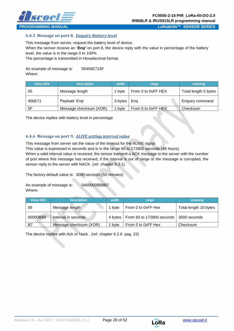
6.4.6 Message on port 9. ALIVE setting interval value
This message from server set the value of the timeout for the ALIVE signal.
This value is expressed in seconds and is in the range 60 to 172800 seconds (48 hours).
When a valid interval value is received, the sensor transmit a ACK message to the server with the number
of port where this message has received, if the interval is out of range or the message is corrupted, the
sensor reply to the server with NACK. (ref. chapter 6.3.1).
The factory default value is: 3000 seconds (50 minutes)
An example of message is: 0400000BB8B7
Where:
Value HEX Description width range meaning
06 Message length 1 byte From 0 to 0xFF Hex Total length 10 bytes
00000BB8 Interval in seconds 4 bytes From 60 to 172800 seconds 3000 seconds
B7 Message checksum (XOR) 1 byte From 0 to 0xFF Hex Checksum
The device replies with Ack or Nack. (ref. chapter 6.2.6 pag. 22)
FC0000-2-15-PIR_LoRa-00-DO-2.0
IR868LR & IRUS915LR programming manual
PROGRAMMING MANUAL LoRaWAN™ SENSOR SERIES
Revision 1.0 – Jun 2017 ©2017 ASCOEL S.r.l. Page 29 of 52 www.ascoel.it
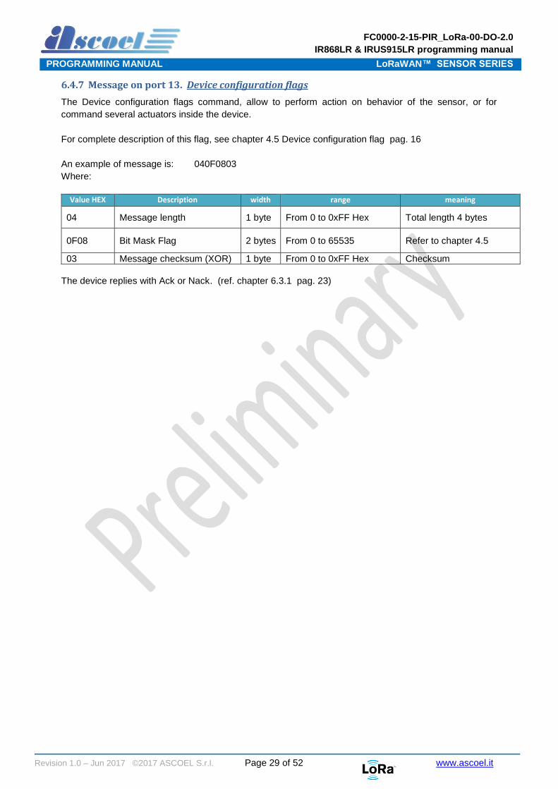
6.4.7 Message on port 13. Device configuration flags
The Device configuration flags command, allow to perform action on behavior of the sensor, or for
command several actuators inside the device.
For complete description of this flag, see chapter 4.5 Device configuration flag pag. 16
An example of message is: 040F0803
Where:
Value HEX Description width range meaning
04 Message length 1 byte From 0 to 0xFF Hex Total length 4 bytes
0F08 Bit Mask Flag 2 bytes From 0 to 65535 Refer to chapter 4.5
03 Message checksum (XOR) 1 byte From 0 to 0xFF Hex Checksum
The device replies with Ack or Nack. (ref. chapter 6.3.1 pag. 23)

FC0000-2-15-PIR_LoRa-00-DO-2.0
IR868LR & IRUS915LR programming manual
PROGRAMMING MANUAL LoRaWAN™ SENSOR SERIES
Revision 1.0 – Jun 2017 ©2017 ASCOEL S.r.l. Page 30 of 52 www.ascoel.it
7 Uart Interface
All of the module’s settings and commands are transmitted over UART using the ASCII interface.
All commands need to be terminated with <CR><LF> and any replies they generate will be terminated by
the same sequence.
The settings for the UART interface are 115200 bps, 8 bits, no parity, 1 Stop bit, no flow control. The baud
rate cannot be changed.
Because the sensor operate in CLASS A in low power state, the UART is put in idle mode for reduce the
consumption. For wake the processor is need send a break condition with length equal to 10mS.
The processor remain in wake condition until the UART continues to receive characters; if the UART don’t
receive data for above 15 seconds, the processor return in sleep mode and for wake it, is necessary send
again the break condition.ote
8 Command Syntax
To issue commands to the ACL868 module, the user sends keywords followed by optional parameters.
Commands and parameters are case insensitive. Hex input data can be uppercase or lowercase.
String text data, such as ON or OFF, is case-insensitive.
Depending on the command, the parameter may expect values in either decimal or hexadecimal form;
refer to the command description for the expected form. For example, when configuring the frequency, the
command expects a decimal value in Hertz such as 869525000 (869.525 MHz).
Alternatively, when configuring the LoRaWAN device address, the hex value is entered into the parameter
as aabbccdd. To enter a number in hex form, use the value directly. For example, the hex value 0xFF
would be entered as FF.
8.1 Command organization
There are four general command categories, as shown in Table 1 Command type
Command Keyword Description
General none Issues various type of command ‘general purpose’
LoRaWAN™ Protocol <mac> Issues LoRaWAN protocol network communication behaviours, actions and configurations commands.
Device <dev> Issues device specific configurations, directly accessing and updating the mode of function
Radio <rad> Issues radio specific configurations, directly accessing and updating the transceiver setup.
System <sys> Issues system level behaviour actions, gathers status information on the firmware and hardware version.
Table 1 Command type
All configuration must be save in the flash memory to avoid lost configuration on the next reboot or reset.
The MAC command, involve the communication behaviours in the LoRaWAN network.
For use the new configuration, the module must be reset with a reboot command or power-on cycle.

FC0000-2-15-PIR_LoRa-00-DO-2.0
IR868LR & IRUS915LR programming manual
PROGRAMMING MANUAL LoRaWAN™ SENSOR SERIES
Revision 1.0 – Jun 2017 ©2017 ASCOEL S.r.l. Page 31 of 52 www.ascoel.it
9 Shell access level
To gain the access to the shell, is mandatory supply the password.
The shell is protected by two password with different level of privileges, in this document the passwords
are named USER and SUPER-USER and are abbreviated with US(user) and SU(super-user) acronym.
The various shell prompt are:
> when no password is entered. In this state the actions are in very limited.
US> when the user password in entered. In this state the actions are partially limited.
SU> when the super user password in entered. In this state the actions are totally enabled.
The command for switch troughs the levels is pw followed by desired level. To gain access with user privileges enter: pw user followed by the password To gain access with super-user privileges enter: pw suser followed by the password The default passwords are different for any sensors and are supplied by ASCOEL. The passwords are modifiable by respective user or super-user.
10 General Command
General commands are used for execute action without supply parameters.
Command Password Description
info no Show various information about the sensor. The informations are depending of the device type.
reboot no Reboot the sensor immediately.
default super-user Load the default parameters. The parameters are depending of the device type
save no Store ALL parameters in flash memory.
pw yes To change password or gain access to the shell
Note
When the SAVE command is entered for store the parameters in flash memory, the access
level will be revoke and the prompt return to > automatically

FC0000-2-15-PIR_LoRa-00-DO-2.0
IR868LR & IRUS915LR programming manual
PROGRAMMING MANUAL LoRaWAN™ SENSOR SERIES
Revision 1.0 – Jun 2017 ©2017 ASCOEL S.r.l. Page 32 of 52 www.ascoel.it
11 MAC Command
MAC commands are common for all type of the sensors and define the access behaviour to the LoRaWAN
network.
Because the MAC commands are very important for the correct operating of the sensors, for varying the
parameters is mandatory accessing to the shell with the super-user password
For showing some parameters, the user level is sufficient.
For access to the shell in super-user mode:
>pw suser <suser password> The prompt will switch to SU>
SU>mac <action> <parameter> <value>
11.1 DevEui Command
Parameter action Password Description
deveui set locked This command sets the globally unique device identifier for the module. The module contains a pre-programmed unique EUI and can be retrieved using the mac get deveui command.
This command is not available for the user.
get User This command returns the globally unique end-device identifier,
as set in the module.
Default: 0000000000000000
Example: mac get deveui
Response example:
deveui 0E7E346401AB02CC
8-bytes hexadecimal number representing the device EUI.

FC0000-2-15-PIR_LoRa-00-DO-2.0
IR868LR & IRUS915LR programming manual
PROGRAMMING MANUAL LoRaWAN™ SENSOR SERIES
Revision 1.0 – Jun 2017 ©2017 ASCOEL S.r.l. Page 33 of 52 www.ascoel.it
11.2 Devaddr Command
Parameter action Password Description
devaddr set Super-user 4-byte hexadecimal number representing the device address, from
00000000 – FFFFFFFF.
The address must be unique in the current network and is used only
for ABP (activation by personalization) devices.
For OTAA (over-the-air activation) this parameter is useless.
Default: 0000000000000000
Example: mac set devaddr 01AB02CC
Response:
devaddr OK if address is valid
devaddr error: invalid value if address is out of range
get User This command will return the current end-device address of the
module.
Default: 00000000
Example: mac get devaddr
Response example:
devaddr 01AB02CC
4-bytes hexadecimal number representing the device address.
11.3 Appeui Command
Parameter action Password Description
appeui set Super-user 8-byte hexadecimal number representing the application EUI.
This command sets the application identifier for the module. The
application identifier should be used to identify device types (sensor
device, lighting device, etc.) within the network.
Default: 0000000000000000
Example: mac set appeui A456FFC199A123F5
Response:
appeui OK if value is valid
appeui error: invalid value if value is out of range
get User This command will return the current application EUI of the module.
Default: 0000000000000000
Example: mac get appeui
Response example:
appeui A456FFC199A123F5
8-bytes hexadecimal number representing the application EUI.

FC0000-2-15-PIR_LoRa-00-DO-2.0
IR868LR & IRUS915LR programming manual
PROGRAMMING MANUAL LoRaWAN™ SENSOR SERIES
Revision 1.0 – Jun 2017 ©2017 ASCOEL S.r.l. Page 34 of 52 www.ascoel.it
11.4 NwkSkey Command
Parameter action Password Description
nwkskey set Super-user 16-byte hexadecimal number representing the network session
key.
The key should remain the same until the communication session
between devices is terminated.
Default: 2B7E151628AED2A6ABF7158809CF4F3C
Example: mac set nwkskey A456FFC199A123F501FA1345CF34F516
Response:
nwkskey OK if value is valid
nwkskey error: invalid value if value is out of range
get Super-user This command will return the current network session key.
Default: 2B7E151628AED2A6ABF7158809CF4F3C
Example: mac get nwkskey
Response example:
nwkskey 2B7E151628AED2A6ABF7158809CF4F3C
16-bytes hexadecimal number representing the network session
key.
11.5 AppSkey Command
Parameter action Password Description
appskey set Super-user 16-byte hexadecimal number representing the application session
key.
This key is unique, created for each occurrence of communication,
when the network requests an action taken by the application
Default: 2B7E151628AED2A6ABF7158809CF4F3C
Example: mac set appskey A456FFC199A123F5
Response:
appskey OK if value is valid
appskey error: invalid value if value is out of range
get Super-user This command will return the current application session key.
Default: 2B7E151628AED2A6ABF7158809CF4F3C
Example: mac get appskey
Response example:
appskey 2B7E151628AED2A6ABF7158809CF4F3C
16-bytes hexadecimal number representing the application session
key.

FC0000-2-15-PIR_LoRa-00-DO-2.0
IR868LR & IRUS915LR programming manual
PROGRAMMING MANUAL LoRaWAN™ SENSOR SERIES
Revision 1.0 – Jun 2017 ©2017 ASCOEL S.r.l. Page 35 of 52 www.ascoel.it
11.6 Appkey Command
Parameter action Password Description
appkey set Super-user 16-byte hexadecimal number representing the application key.
The application key is used to identify a grouping over module units
which perform the same or similar task
Default: 2B7E151628AED2A6ABF7158809CF4F3C
Example: mac set appkey A456FFC199A123F5
Response:
appkey OK if value is valid
appkey error: invalid value if value is out of range
get Super-user This command will return the current application key.
Default: 2B7E151628AED2A6ABF7158809CF4F3C
Example: mac get appkey
Response example:
appkey 2B7E151628AED2A6ABF7158809CF4F3C
16-bytes hexadecimal number representing the application session
key.
11.7 Pwridx Command (in current FW revision this command is disabled)
Parameter action Password Description
pwridx set Super-user Decimal number representing the index value for the output power,
from 0 to 5 for 433 MHz frequency band and from 1 to 5 for 868
MHz frequency band.
Default: 5
Example: mac set pwridx 5
Response:
pwridx OK if value is valid
pwridx error: invalid value if value is out of range
get User This command will return the current application session key.
Default: 5
Example: mac get pwridx
Response example:
pwridx 5
1-bytes decimal number representing the RF power.

FC0000-2-15-PIR_LoRa-00-DO-2.0
IR868LR & IRUS915LR programming manual
PROGRAMMING MANUAL LoRaWAN™ SENSOR SERIES
Revision 1.0 – Jun 2017 ©2017 ASCOEL S.r.l. Page 36 of 52 www.ascoel.it
11.8 Dr Command (in current FW revision this command is disabled)
Parameter action Password Description
dr set Super-user Decimal number representing the data rate, from 0 and 7, but within
the limits of the data rate range for the defined channels.
This command sets the data rate to be used for the next
transmission. Please refer to the LoRaWAN™ Specification for the
description of data rates and the corresponding spreading factors
Default: 0
Example: mac set dr 3
Response:
dr OK if value is valid
dr error: invalid value if value is out of range
get User This command will return the current datarate.
Default: 0
Example: mac get dr
Response example:
dr 3
1-bytes decimal number representing the data rate.
11.9 Adr Command
Parameter action Password Description
adr set Super-user This command turn ON or OFF the adaptive data rate (ADR)
control. The server is informed about the status of the module’s
ADR in every uplink frame it receives from the ADR field in uplink
data packet. If ADR is enabled, the server will optimize the data rate
and the transmission power of the module based on the information
collected from the network.
Default: ON
Example: mac set adr ON
Response:
adr OK if value is valid
adr error: invalid value if value is out of range
get User This command will return the state of ADR control.
Default: ON
Example: mac get adr
Response example:
adr OFF
ON or OFF string.

FC0000-2-15-PIR_LoRa-00-DO-2.0
IR868LR & IRUS915LR programming manual
PROGRAMMING MANUAL LoRaWAN™ SENSOR SERIES
Revision 1.0 – Jun 2017 ©2017 ASCOEL S.r.l. Page 37 of 52 www.ascoel.it
11.10 Confirmed/unconfirmed port Command
Parameter action Password Description
confport set Super-user A confirmed message will expect an acknowledgment from the
server; otherwise, the message will be retransmitted by the number
indicated by the command mac set retry <value>, whereas
an unconfirmed message will not expect any acknowledgment
back from the server. Please refer to the LoRaWAN™ Specification
for further details.
The confport command, permit to set until 10 ports where the
message will be treated as confirmed type.
For example, if desired that message send on the port 20 will be
confirmed type, the command is mac confport 20.
Is possible set up to 10 ports for use as confirmed,
Every time that mac confport <port number> is entered, the
<port number> is added to the list. If the list is full or if the port
number is invalid or already present, the processor answer with
error message.
For delete all list, the command is: mac confport none
Default: 0 (no confirmed port)
Example: mac set confport 3
Response:
confport OK if value is valid
confport error: invalid value if value is out of range
get User This command will return the list of confirmed ports.
Default: 000 000 000 000 000 000 000 000 000 000
Example: mac get confport
Response example:
Confport 008 020 031 000 000 000 000 000 000 000
A list of decimal values of port number.

FC0000-2-15-PIR_LoRa-00-DO-2.0
IR868LR & IRUS915LR programming manual
PROGRAMMING MANUAL LoRaWAN™ SENSOR SERIES
Revision 1.0 – Jun 2017 ©2017 ASCOEL S.r.l. Page 38 of 52 www.ascoel.it
11.11 Retry Command
Parameter action Password Description
retry set Super-user Decimal number representing the number of retransmissions for an
uplink confirmed packet, from 1 to 8.
Default: 1
Example: mac set retry 3
Response:
retry OK if value is valid
retry error: invalid value if value is out of range
get User This command will return the current retry number.
Default: 0
Example: mac get retry
Response example:
retry 3
1-bytes decimal number representing the number of
retransmissions, from 1 to 8.
11.12 Link Check Command
Parameter action Password Description
linkchk set Super-user Decimal number that sets the time interval in seconds for the link
check process, from 0 to 65535.
This command sets the time interval for the link check process to
be triggered periodically. A <value> of ‘0’ will disable the link
check process. When the time interval expires, the next application
packet that will be sent to the server will include also a link check
MAC command. Please refer to the LoRaWAN™ Specification for
more information on the Link Check MAC command
Default: 0
Example: mac set linkchk 600
Response:
linkchk OK if value is valid
linkchk error: invalid value if value is out of range
get User This command will return the current link check interval.
Default: 0
Example: mac get linkchk
Response example:
linkchk 600
Decimal number representing the interval in seconds for the next
link check test.

FC0000-2-15-PIR_LoRa-00-DO-2.0
IR868LR & IRUS915LR programming manual
PROGRAMMING MANUAL LoRaWAN™ SENSOR SERIES
Revision 1.0 – Jun 2017 ©2017 ASCOEL S.r.l. Page 39 of 52 www.ascoel.it
11.13 Rx delay1 Command
Parameter action Password Description
rxdelay1 set Super-user Decimal number representing the delay between the transmission
and the first Reception window in milliseconds, from 0 to 65535.
This command will set the delay between the transmission and the
first Reception window to the <rxDelay> in milliseconds. The
delay between the transmission and the second Reception window
is calculated in software as the delay between the transmission and
the first Reception window + 1000 (ms).
Default: 1000
Example: mac set rxdelay1 1500
Response:
rxdelay1 OK if value is valid
rxdelay1 error: invalid value if value is out of range
get User This command will return the current RX1 delay.
Default: 0
Example: mac get rxdelay1
Response example:
rxdelay1 1500
Decimal number representing the RX1 delay in mS.
11.14 Rx2 frequency Command
Parameter action Password Description
rx2freq set Super-user Decimal number representing the frequency, from 863000000 to
870000000 Hz.
This command sets the frequency for the second Receive window.
The configuration of the Receive window parameters must be in
concordance with the server configuration
Default: 869525000
Example: mac set rx2freq 869525000
Response:
rx2freq OK if value is valid
rx2freq error: invalid value if value is out of range
get User This command will return the current second Receive window
frequency.
Default: 869525000
Example: mac get rx2freq
Response example:
rx2freq 869525000
Decimal number representing the frequency in Hz.

FC0000-2-15-PIR_LoRa-00-DO-2.0
IR868LR & IRUS915LR programming manual
PROGRAMMING MANUAL LoRaWAN™ SENSOR SERIES
Revision 1.0 – Jun 2017 ©2017 ASCOEL S.r.l. Page 40 of 52 www.ascoel.it
11.15 Rx2 data rate Command
Parameter action Password Description
rx2dr set Super-user Decimal number representing the data rate for RX2, from 0 to 7.
This command sets the data rate for the second Receive window.
The configuration of the Receive window parameters must be in
concordance with the server configuration
Value Spreading factor
0 SF12
1 SF11
2 SF10
3 SF9
4 SF8
5 SF7
6 FSK
7 TBD
Default: 0
Example: mac set rx2dr 3
Response:
rx2dr OK if value is valid
rx2dr error: invalid value if value is out of range
get User This command will return the current datarate in RX2 window.
Default: 0
Example: mac get rx2dr
Response example:
rx2dr 3
Decimal number representing spreading factor used in RX2
window.

FC0000-2-15-PIR_LoRa-00-DO-2.0
IR868LR & IRUS915LR programming manual
PROGRAMMING MANUAL LoRaWAN™ SENSOR SERIES
Revision 1.0 – Jun 2017 ©2017 ASCOEL S.r.l. Page 41 of 52 www.ascoel.it
11.16 Duty cycle Command
Parameter action Password Description
dutycycle set Super-user This command enable or disable the control of dutycycle.
The duty cycle of radio devices is often regulated by government.
If this is the case, the duty cycle is commonly set to 1%, but make
sure to check the regulations of your local government to be sure.
In Europe, duty cycles are regulated by section 7.2.3 of the ETSI
EN300.220 standard.
Please refer to the LoRaWAN™ Specification for further details.
The control should be turned OFF ONLY for test purpose.
Default: ON
Example: mac set dutycycle ON
Response:
dutycycle OK if value is valid
dutycycle error: invalid value if value is out of range
get User This command will return the state of Duty Cycle control.
Default: ON
Example: mac get dutycycle
Response example:
Dutycycle OFF
ON or OFF string.

FC0000-2-15-PIR_LoRa-00-DO-2.0
IR868LR & IRUS915LR programming manual
PROGRAMMING MANUAL LoRaWAN™ SENSOR SERIES
Revision 1.0 – Jun 2017 ©2017 ASCOEL S.r.l. Page 42 of 52 www.ascoel.it
11.17 OTAA Command
Parameter action Password Description
otaa set Super-user This command choice the method of provisioning the sensor on the
network server.
If OTAA is set to YES, automatically the ABP (Activation By
Personalization) is switched OFF.
Vice-versa if OTAA is set to NO, the ABP mode is enabled.
Please refer to the LoRaWAN™ Specification for further details.
Default: NO
Example: mac set otaa ON
Response:
otaa OK if value is valid
otaa error: invalid value if value is out of range
get User This command will return the state of OTAA.
Default: ON
Example: mac get otaa
Response example:
Otaa YES
YES or NO string.
11.18 Class Command
Parameter action Password Description
class set Super-user This command choice the class of operation of the device.
The available class are A or C.
Please refer to the LoRaWAN™ Specification for further details.
Default: A
Example: mac set class C
Response:
class OK if value is valid
class error: invalid value if value is out of range
get User This command will return the selected Class.
Default: ON
Example: mac get class
Response example:
class C
A or C string.

FC0000-2-15-PIR_LoRa-00-DO-2.0
IR868LR & IRUS915LR programming manual
PROGRAMMING MANUAL LoRaWAN™ SENSOR SERIES
Revision 1.0 – Jun 2017 ©2017 ASCOEL S.r.l. Page 43 of 52 www.ascoel.it
11.19 Password Command
Parameter action Password Description
pw none Super-user
or
User
This command allow to change the current password or to gain the
access to the shell.
Every sensors are shipped with a specific set of passwords; these
passwords are supplied by ASCOEL when the device is shipped.
The passwords are freely modifiable by the user or super-user in according with the own level access; for do this is mandatory enter the own level password for set the new password. The max length password is 16 characters. Example: The current user password is ‘user’ and the current super-user password is ‘suser’
For gain access to the shell in user level: pw user <current password>
pw user user
For gain access to the shell in super-user level: pw suser <current password>
pw suser suser
For change the user level password the command is: pw set user <current user pw> <new user pw>
pw set user user newpassword
For gain access to the shell in super-user level: pw set suser <current super pw> <new super pw>
pw set suser suser newpassword
Response:
user OK if value is valid
user error

FC0000-2-15-PIR_LoRa-00-DO-2.0
IR868LR & IRUS915LR programming manual
PROGRAMMING MANUAL LoRaWAN™ SENSOR SERIES
Revision 1.0 – Jun 2017 ©2017 ASCOEL S.r.l. Page 44 of 52 www.ascoel.it
11.20 Default Command
Parameter action Password Description
default none Super-user This command allow loading the factory default values for all
parameters.
This command is executed only with super-user privileges. Example: default
Response:
default OK if value is valid default error
11.21 Save Command
Parameter action Password Description
save none none This command store all parameters in non-volatile flash memory.
Example: save
Response:
save OK if value is valid save error
11.22 Reboot Command
Parameter action Password Description
reboot none none Performs a reboot of the sensors. Example: reboot
Response:
none
11.23 Info Command
Parameter action Password Description
info none none Show some data or parameters related to the sensor. The response format is not and vary between firmware releases and sensors type. Example: info
Response:
none

FC0000-2-15-PIR_LoRa-00-DO-2.0
IR868LR & IRUS915LR programming manual
PROGRAMMING MANUAL LoRaWAN™ SENSOR SERIES
Revision 1.0 – Jun 2017 ©2017 ASCOEL S.r.l. Page 45 of 52 www.ascoel.it
12 IR868LR specific shell command (DEV)
DEV commands are specific for every one type of the sensor and define the operating behaviour for which
sensors was developed.
Because the DEV commands allow setting some vital parameters, the shell level access can be of type
USER or SUPERUSER.
For showing only DEV parameters, the user level is sufficient.
For access to the shell in superuser mode:
>pw suser <suser password> The prompt will switch to SU>
For access to the shell in user mode:
>pw user <user password> The prompt will switch to US>
12.1 Alive interval Command
Parameter action Password Description
alive set Superuser The alive interval allows you to set a time expressed in seconds
that regularly transmits a data packet to the server.
For the contents of the packet, refer to the specific device manual.
Default: 3000 (min. 15 max 172800 seconds)
Example: dev set alive 5000
Response:
alive OK if value is valid
alive error: invalid value if value is out of range
get User This command will return the value of alive interval.
Default: 3000
Example: dev get alive
Response example:
alive 18000
A decimal values of alive interval, in seconds.
FC0000-2-15-PIR_LoRa-00-DO-2.0
IR868LR & IRUS915LR programming manual
PROGRAMMING MANUAL LoRaWAN™ SENSOR SERIES
Revision 1.0 – Jun 2017 ©2017 ASCOEL S.r.l. Page 46 of 52 www.ascoel.it
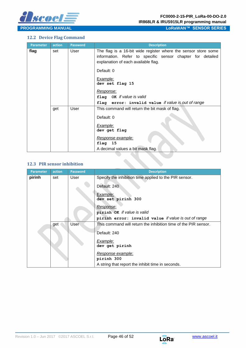
12.2 Device Flag Command
Parameter action Password Description
flag set User The flag is a 16-bit wide register where the sensor store some
information. Refer to specific sensor chapter for detailed
explanation of each available flag.
Default: 0
Example: dev set flag 15
Response:
flag OK if value is valid
flag error: invalid value if value is out of range
get User This command will return the bit mask of flag.
Default: 0
Example: dev get flag
Response example:
flag 15
A decimal values a bit mask flag.
12.3 PIR sensor inhibition
Parameter action Password Description
pirinh set User Specify the inhibition time applied to the PIR sensor.
Default: 240
Example: dev set pirinh 300
Response:
pirinh OK if value is valid
pirinh error: invalid value if value is out of range
get User This command will return the inhibition time of the PIR sensor.
Default: 240
Example: dev get pirinh
Response example:
pirinh 300
A string that report the inhibit time in seconds.

FC0000-2-15-PIR_LoRa-00-DO-2.0
IR868LR & IRUS915LR programming manual
PROGRAMMING MANUAL LoRaWAN™ SENSOR SERIES
Revision 1.0 – Jun 2017 ©2017 ASCOEL S.r.l. Page 47 of 52 www.ascoel.it
12.4 MODE 1
Parameter action Password Description
mode1 set User Setting of the mode1 of the functionally of the PIR sensor.
Syntax: mode1 (no parameter needed)
Default: nothing
Example: dev set mode1
Response:
mode1 OK if value is valid
mode1 error: invalid value if value is out of range
12.5 MODE 2
Parameter action Password Description
mode2 set User Setting of the mode2 of the functionally of the PIR sensor.
Syntax: mode2 <counter number> <flag>
Default: counter number 1
flag 0
Example: dev set mode2 20 1
Response:
mode2 OK if value is valid
mode2 error: invalid value if value is out of range
12.6 MODE 3
Parameter action Password Description
mode3 set User Setting of the mode3 of the functionally of the PIR sensor.
Syntax: mode3 <interval time> <counter number> <flag>
Default: interval time 15 seconds
counter number 1
flag 0
Example: dev set mode3 20 5 2
Response:
mode3 OK if value is valid
mode3 error: invalid value if value is out of range
FC0000-2-15-PIR_LoRa-00-DO-2.0
IR868LR & IRUS915LR programming manual
PROGRAMMING MANUAL LoRaWAN™ SENSOR SERIES
Revision 1.0 – Jun 2017 ©2017 ASCOEL S.r.l. Page 48 of 52 www.ascoel.it
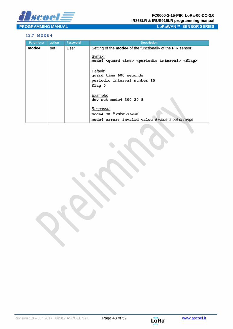
12.7 MODE 4
Parameter action Password Description
mode4 set User Setting of the mode4 of the functionally of the PIR sensor.
Syntax: mode4 <guard time> <periodic interval> <flag>
Default: guard time 600 seconds
periodic interval number 15
flag 0
Example: dev set mode4 300 20 8
Response:
mode4 OK if value is valid
mode4 error: invalid value if value is out of range

FC0000-2-15-PIR_LoRa-00-DO-2.0
IR868LR & IRUS915LR programming manual
PROGRAMMING MANUAL LoRaWAN™ SENSOR SERIES
Revision 1.0 – Jun 2017 ©2017 ASCOEL S.r.l. Page 49 of 52 www.ascoel.it
12.8 Mode Command (get only)
Parameter action Password Description
mode get User This command will return the MODE currently programmed.
Example: dev get mode
Response example for:
MODE1:
mode 1
MODE2:
Syntax: mode 2 <counter number> <flag>
Example: mode 2 15 2
MODE3:
Syntax: mode 3 <interval time> <counter number>
<flag>
Example: mode 3 300 20 2
MODE4:
Syntax: mode 4 <guard time> <periodic interval>
<flag>
Example: mode 3 600 60 8
FC0000-2-15-PIR_LoRa-00-DO-2.0
IR868LR & IRUS915LR programming manual
PROGRAMMING MANUAL LoRaWAN™ SENSOR SERIES
Revision 1.0 – Jun 2017 ©2017 ASCOEL S.r.l. Page 50 of 52 www.ascoel.it
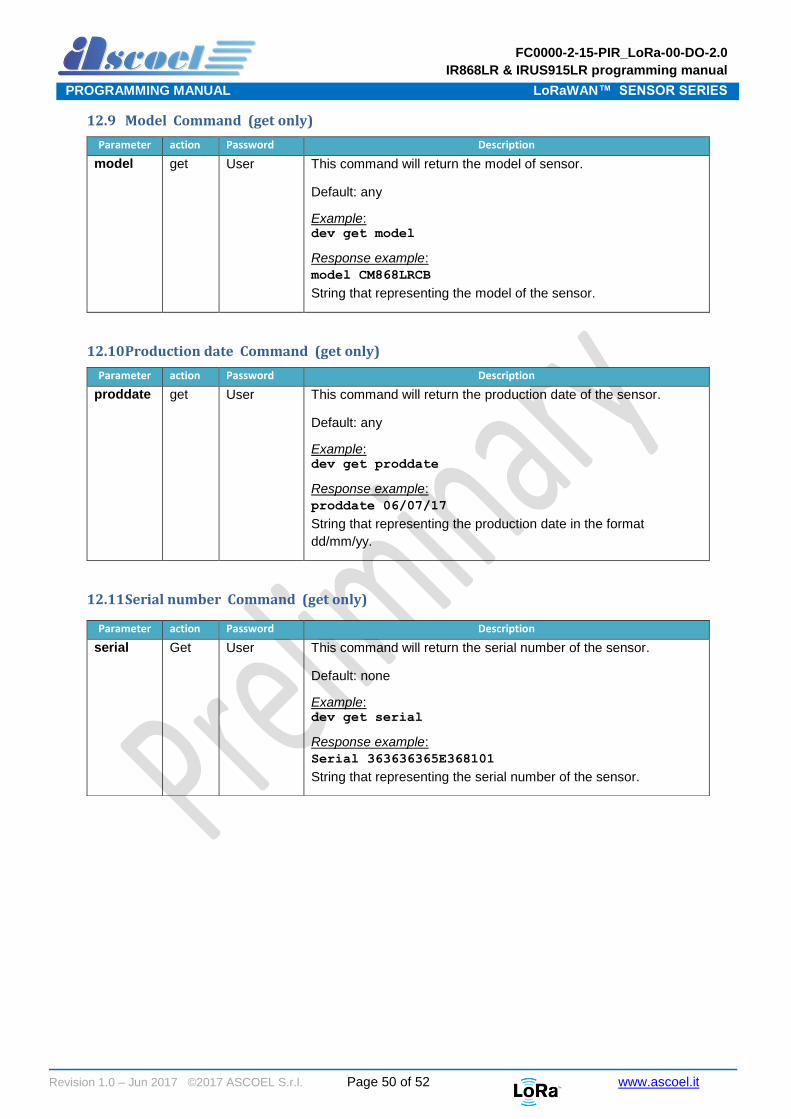
12.9 Model Command (get only)
Parameter action Password Description
model get User This command will return the model of sensor.
Default: any
Example: dev get model
Response example:
model CM868LRCB
String that representing the model of the sensor.
12.10 Production date Command (get only)
Parameter action Password Description
proddate get User This command will return the production date of the sensor.
Default: any
Example: dev get proddate
Response example:
proddate 06/07/17
String that representing the production date in the format
dd/mm/yy.
12.11 Serial number Command (get only)
Parameter action Password Description
serial Get
User This command will return the serial number of the sensor.
Default: none
Example: dev get serial
Response example:
Serial 363636365E368101
String that representing the serial number of the sensor.
FC0000-2-15-PIR_LoRa-00-DO-2.0
IR868LR & IRUS915LR programming manual
PROGRAMMING MANUAL LoRaWAN™ SENSOR SERIES
Revision 1.0 – Jun 2017 ©2017 ASCOEL S.r.l. Page 51 of 52 www.ascoel.it
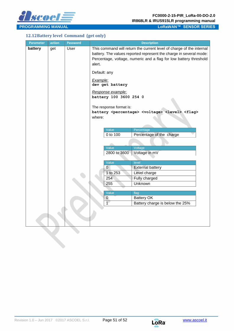
12.12 Battery level Command (get only)
Parameter action Password Description
battery get User This command will return the current level of charge of the internal
battery. The values reported represent the charge in several mode:
Percentage, voltage, numeric and a flag for low battery threshold
alert.
Default: any
Example: dev get battery
Response example:
battery 100 3600 254 0
The response format is:
battery <percentage> <voltage> <level> <flag>
where:
Value Percentage
0 to 100 Percentage of the charge
Value Voltage
2800 to 3600 Voltage in mV
Value level
0 External battery
1 to 253 Level charge
254 Fully charged
255 Unknown
Value flag
0 Battery OK
1 Battery charge is below the 25%

FC0000-2-15-PIR_LoRa-00-DO-2.0
IR868LR & IRUS915LR programming manual
PROGRAMMING MANUAL LoRaWAN™ SENSOR SERIES
Revision 1.0 – Jun 2017 ©2017 ASCOEL S.r.l. Page 52 of 52 www.ascoel.it
© Ascoel 2017 Reproduction in whole or in part is prohibited without the prior written consent of ASCOEL. The information presented in this document does not form part of any quotation or contract, is believed to be accurate and reliable and may be changed without notice. No liability will be accepted by the publisher for any consequence of its use. Publication thereof does not convey nor imply any license under patent or other industrial or intellectual property rights. ASCOEL assumes no responsibility or liability whatsoever for any failure or unexpected operation resulting from misuse.
Contact Information
ASCOEL Srl Via degli Artigiani 7 26025 Pandino -CR- ITALY Phone: (+39)0373 970473 E-mail: [email protected] Internet: http://www.ascoel.it