IPS-C-IN-160(1) - N.I.G.Cigs.nigc.ir/STANDS/IPS/C-IN-160.pdf · ISA (INSTRUMENT SOCIETY OF AMERICA)...
28
IPS-C-IN-160(1)
Transcript of IPS-C-IN-160(1) - N.I.G.Cigs.nigc.ir/STANDS/IPS/C-IN-160.pdf · ISA (INSTRUMENT SOCIETY OF AMERICA)...
IPS-C-IN-160(1)
FOREWORD
This Standard is intended to be used within and for Iranian Ministry of Petroleum (N.I.O.C, N.I.G.C, N.P.C., N.I.O.R.D.C. and other affiliate organizations and companies) and has been prepared on the basis of the recognized standards, scientific publications, technical documents, accumulated knowledge and experiences in petroleum industries at national and international levels.
Iranian Petroleum Standards are prepared by Iranian Petroleum Standards Organization reviewed and amended by the relevant technical standard committees to incorporate acceptable comments made by oil, gas and petrochemical experts.
Standards are finally approved by the “Standards High Council” of Iranian Ministry of Petroleum.
Iranian Petroleum Standards (IPS) are subject to amendment withdrawal, if required, thus the latest edition of IPS shall be applicable.
Any comment or recommendation submitted to the “Iranian Petroleum Standards Organization” will be evaluated in the relevant technical committee and will be considered in the next revision, upon approval.
GENERAL DEFINITIONS:
Throughout this Standard the following definitions shall apply.
“COMPANY” : Refers to one of the related and/or affiliated companies of the Iranian Ministry of Petroleum such as National Iranian Oil Company, National Iranian Gas Company, National Petrochemical Company etc.
“PURCHASER” : Means the “Company “ Where this standard is part of direct purchaser order by the “Company”, and the “Contractor” where this Standard is a part of contract documents.
“VENDOR” and “SUPPLIER” : Refers to firm or person who will supply and/or fabricate the equipment or material.
“WILL” : Is normally used in connection with the action by the “Company” rather than by a contractor, supplier or vendor.
“MAY” : Is used where a provision is completely discretionary.
“SHOULD” : Is used where a provision is advisory only.
“SHALL” : Is used where a provision is mandatory.
IRANIAN PETROLEUM STANDARDS.
No. 19, Street 14, North Kheradmand Karimkhan Avenue, Tehran, Iran. Tel. : 66153055 : 88810460 Fax. : 88810462
Aug. 2003
CONSTRUCTION AND INSTALLATION STANDARD
FOR
CONTROL VALVES
FIRST EDITION
AUGUST 2003
This Standard is the property of Iranian Ministry of Petroleum. All rights are reserved to the owner. Neither whole nor any part of this document may be disclosed to any third party, reproduced, stored in any retrieval system or transmitted in any form or by any means without the prior written consent of the Iranian Ministry of Petroleum.
Aug. 2003
IPS-C-IN-160(1)
1
CONTENTS : PAGE No.
1. SCOPE ............................................................................................................................................ 2
2. REFERENCES ................................................................................................................................ 2
3. UNITS .............................................................................................................................................. 2
4. CONTROL VALVE INSTALLATION (GENERAL) ......................................................................... 2
5. ACTUATOR INSTALLATION......................................................................................................... 4
5.1 Pneumatic Diaphragm Actuators .......................................................................................... 4
5.2 Motor-Operated Valve Actuators........................................................................................... 4
5.3 Electro-Pneumatic Converters (Transducers) ..................................................................... 4
5.4 Air Lock Devices ..................................................................................................................... 4
5.5 Solenoid-Operated Valves ..................................................................................................... 4
5.6 Pneumatic Cylinder Actuators............................................................................................... 6
5.7 Hydraulic Cylinder Actuators ................................................................................................ 6
6. BLOCK AND BYPASS VALVES.................................................................................................... 9
7. DIMENSIONS OF CONTROL VALVES ....................................................................................... 10
8. MANIFOLD PIPING ARRANGEMENT......................................................................................... 10
9. SUMMARY OF INSTALLATION PRACTICES ............................................................................ 23
10. CONTROL VALVE TEST REQUIREMENTS (GENERAL) ........................................................ 23
Aug. 2003
IPS-C-IN-160(1)
2
1. SCOPE
This Standard represents the minimum and general technical requirements for the installation of different types of control valves and their accessories, which are used in oil, gas and petrochemical industries. In any case, manufacturer’s installation instructions should be strictly followed.
Note: This is a revised version of the standard specification for control valves, which is issued as revision (1). Revision (0) of the said standard specification is withdrawn.
2. REFERENCES
Throughout this Standard the following dated and undated standards/codes are referred to. These referenced documents shall, to the extent specified herein, form a part of this standard. For dated references, the edition cited applies. The applicability of changes in dated references that occur after the cited date shall be mutually agreed upon by the Company and the Vendor. For undated references, the latest edition of the referenced documents (including any supplements and amendments) applies.
API (AMERICAN PETROLEUM INSTITUTE)
RP-550 "Manual on Installation of Refinery Instruments and Control system"
Part 1-Section 6 "Control Valve and Accessories", 1985
ANSI (AMERICAN NATIONAL STANDARD INSTITUTION)
B-16.34 "Valves, Flanged and Buttwelding End"
B-16.37 "Hydrostatic Testing of Control Valves", 1980
BSI (BRITISH STANDARDS INSTITUTION)
BS-5155 "Specification for Butterfly Valves", (1984)
ISA (INSTRUMENT SOCIETY OF AMERICA)
ISA-RP-75.06 "Control Valve Manifold Design"
IPS (IRANIAN PETROLEUM STANDARDS)
IPS-E-PR-230 “Engineering Standard for Piping and Instrumentation Diagram”
IPS-E-EL-110 “Electrical Area Classification”
IPS-E-IN-100 Part I Hazardous Area Classification
3. UNITS
This Standard is based on International System of Units (SI), except for temperature which is in degree C instead of kelvin, pipe and fitting threads which are in inches of NPT.
4. CONTROL VALVE INSTALLATION (GENERAL)
4.1 Control valves shall be installed so that they are readily accessible from grade or platforms. Wherever possible, they shall be located at grade for ease of maintenance.
4.2 Wherever possible control valves shall be installed with stems vertically above the body. Where line conditions prohibit this, suitable support must be provided for the valve top-works.
Aug. 2003
IPS-C-IN-160(1)
3
4.3 Where equipment must be observed, while on manual control, the control valve shall be installed adjacent to the equipment.
4.4 Clearance shall be provided above and below a control valve so that the bottom flange and plug or the top-works and plug may be removed with the valve body in the pipeline.
4.5 The valve body may swing around a selected bolt axis for maintenance access. However clearance still being provided to enable inspection of the valve plug without rotating the valve in the pipeline.
4.6 Control valves shall have removable trims and sufficient clearance shall be allowed for access and removal.
4.7 Clearance also shall be provided for hand wheel operation and positioner maintenance.
4.8 Control valves at fired heaters shall be located 15 m away from burners so that maintenance can be carried out without danger of flash-back.
4.9 Control valves for flammable and volatile fluids shall not be installed adjacent to hot pumps, lines or equipment.
4.10 Control valves shall be located so that diaphragms and electric or electronic components are not damaged by heat radiated from vessels, heaters and other equipment.
4.11 Where it is necessary to reduce from line size to control valve size, swaged reducers shall be used between the block valves and the control valve. Sufficient spacing between block valves shall allow for installation of larger size control valves.
4.12 The computed valve size should be at least one pipe size smaller than lines in which control valves are installed.
4.13 For toxic or other dangerous duties control valve stems shall be bellows sealed, with an independent gland seal, the enclosed space being monitored for bellows leakage.
4.14 When sealing is not possible a purging system that monitors flow failure shall be used.
4.15 Control valve vent and drain connections shall not be less than ¾ inch nominal bore.
4.16 Butterfly valves shall be installed with their shafts horizontal.
4.17 Where butterfly valves have to be installed in vertical lines, care shall be taken that the diaphragm actuator stays clear from the piping.
4.18 Control valves shall be installed in main lines but not in long straight runs. In the case of long straight runs, the control valves shall be offset from the main line so that they will not be subjected to line stresses caused. e.g. by thermal expansion and weight of unsupported lines.
4.19 Extra clearance shall be provided where extension bonnets or accessories are used. Clearance should also be provided on the side of the control valve for maintenance of positioners and other devices.
4.20 Long bolting used with flangeless valves can expand when exposed to fire and cause leakage. A fire deflection shield and/or insulation is recommended.
4.21 Certain rotary-motion control valve types utilize low-friction plastic lined bearings and as a result are susceptible to static electricity, shall be grounded. Manufacturer’s recommendations shall be followed.

Aug. 2003
IPS-C-IN-160(1)
4
5. ACTUATOR INSTALLATION
Electrically operated items such as motor actuators, solenoid valves, converters shall be approved for installation under the applicable hazardous area classifications. Refer to IPS-E-IN-100 Part I for hazardous area classification.
5.1 Pneumatic Diaphragm Actuators
5.1.1 Sliding stem spring loaded diaphragm actuators with air as the operating medium shall be installed vertically above the body, if piping condition prohibit this, manufacturer recommendation should be considered.
5.2 Motor-Operated Valve Actuators
5.2.1 The M.O.V. actuator shall be an integral unit suitable for direct mounting on the valve stem at any position. The unit shall be self centering and no special alignment should be required.
5.2.2 Electric-Motor driven actuators should be mounted so that the motor is above the gear box. This arrangement prevents gear oil from saturating the motor windings.
5.3 Electro-Pneumatic Converters (Transducers)
5.3.1 Electro-Pneumatic converters where required, shall be furnished and mounted independent of the control valve.
5.3.2 Standard mounting hardware shall be provided for mounting electro-pneumatic converter on a pipestand, or a panel.
5.3.3 Electro-pneumatic converters shall not be mounted on control valves. Sufficient capacity must be allowed in the pneumatic circuit to prevent interaction between converters and valve positions. Where there is no possibility of local vibration ruining the valve positioner, consideration shall be given to the use of valve mounted electropneumatic valve positioner.
5.3.4 Where two valves are used in the three-way service, one common controller and electro-pneumatic converter shall be used for both valves. Air supply to this converter shall be the same as the valve positioners and air locks.
5.4 Air Lock Devices
5.4.1 Air lock-up device shall be provided for all services requiring that the control valve remains in the position in which it was immediately before the air failure. On control valve with a positioner, the lock-up valve shall be installed between the positioner output and the actuator.
5.4.2 If air lock valves are specified, they shall be installed as close to the valve actuator as possible. However, any solenoid valves associated with protective system shall be installed between the air lock valve and the actuator. The air supply for the air lock shall be the same as for the valve positioner.
5.4.3 Valves with the air lock feature shall, in addition, have the following:
a) A pressure gage indicating actual diaphragm pressure, for diaphragm actuators.
b) A pressure gage indicating air volume reserve tank pressure, for piston actuators.
5.5 Solenoid-Operated Valves
5.5.1 Solenoid-operated valves are extremely versatile and are frequently used with the control valves in a variety of on-off or switching applications such as equipment override, fail-safe interlock with two valves, and switching from one instrument or pressure line to another.

Aug. 2003
IPS-C-IN-160(1)
5
5.5.2 A typical solenoid valve installation on a pneumatically operated control valve is shown in Fig. 1. The solenoid valve is normally open and allows the positioner output into the diaphragm case. Upon a power loss, the solenoid valve closes the port to the valve positioner and bleeds pressure
from the diaphragm case of the control valve.
TYPICAL INSTALLATION OF ASOLENOID VALVE Fig. 1
5.5.3 Where solenoid valves are installed in control air supplies to pneumatically operated valves to seal-in diaphragm pressure, in the event of an electrical failure, the solenoid valves should incorporate a time delay and hand re-set to prevent operation resulting from transient interruptions of the electrical supply.
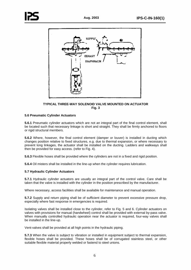
5.5.4 Various solenoid/actuator mounting arrangements are shown in (Fig. 2, 3) below.
TYPICAL FOUR-WAY SOLENOID VALVE MOUNTED ON ACTUATOR
Fig. 2
Aug. 2003
IPS-C-IN-160(1)
6
TYPICAL THREE-WAY SOLENOID VALVE MOUNTED ON ACTUATOR Fig. 3
5.6 Pneumatic Cylinder Actuators
5.6.1 Pneumatic cylinder actuators which are not an integral part of the final control element, shall be located such that necessary linkage is short and straight. They shall be firmly anchored to floors or rigid structural members.
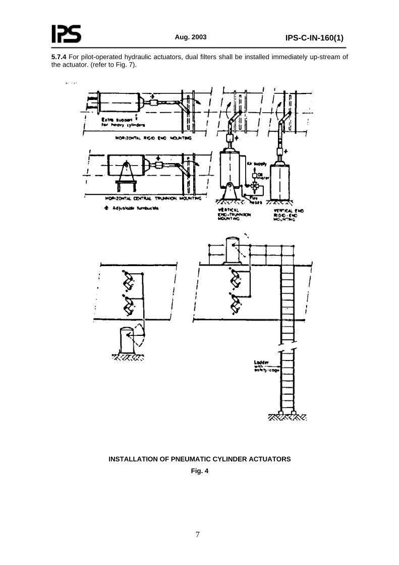
5.6.2 Where, however, the final control element (damper or louver) is installed in ducting which changes position relative to fixed structures, e.g. due to thermal expansion, or where necessary to prevent long linkages, the actuator shall be installed on the ducting. Ladders and walkways shall then be provided for easy access. (refer to Fig. 4).
5.6.3 Flexible hoses shall be provided where the cylinders are not in a fixed and rigid position.
5.6.4 Oil misters shall be installed in the line-up when the cylinder requires lubrication.
5.7 Hydraulic Cylinder Actuators
5.7.1 Hydraulic cylinder actuators are usually an integral part of the control valve. Care shall be taken that the valve is installed with the cylinder in the position prescribed by the manufacturer.
Where necessary, access facilities shall be available for maintenance and manual operation.
5.7.2 Supply and return piping shall be of sufficient diameter to prevent excessive pressure drop, especially where fast response in emergencies is required.
Isolating valves shall be installed close to the cylinder, refer to Fig. 5 and 6. Cylinder actuators on valves with provisions for manual (handwheel) control shall be provided with external by-pass valve. When manually controlled hydraulic operation near the actuator is required, four-way valves shall be installed in the line-up.
Vent-valves shall be provided at all high points in the hydraulic piping.
5.7.3 When the valve is subject to vibration or installed in equipment subject to thermal expansion, flexible hoses shall be provided. These hoses shall be of corrugated stainless steel, or other suitable flexible material properly welded or fastend to steel unions.
Aug. 2003
IPS-C-IN-160(1)
7
5.7.4 For pilot-operated hydraulic actuators, dual filters shall be installed immediately up-stream of the actuator. (refer to Fig. 7).
INSTALLATION OF PNEUMATIC CYLINDER ACTUATORS
Fig. 4

Aug. 2003
IPS-C-IN-160(1)
8
INSTALLATION OF HYDRAULIC CYLINDER ACTUATORS
Fig. 7

Aug. 2003
IPS-C-IN-160(1)
9
6. BLOCK AND BYPASS VALVES
6.1 A block and by-pass valve system may not be necessary where the process can be shut down to repair the control valve without significant economic loss, or where the process can not be feasibly operated on the by-pass.
6.2 The consequences of shutting down a process unit to perform a simple task (such as replacing control valve packing) should always be considered.
6.3 In cases where the block and by-pass valves are not used, some users require that the control valve be equipped with a handwheel or other operating device. A permanent side mounted hand wheel shall be fitted to the control valve.
Where the cost of the hand wheel is greater than the cost of block and by-pass valves, the latter shall be provided except on hydrogen service and protective service.
6.4 Where the greatest flexibility is to be provided for future expansion, the block valves upstream and downstream of the control valve shall be line size. In situations where the control valve is two or more sizes smaller than line size, the block valves may be one size smaller than line size.
6.5 A by-pass connection and valve shall be installed around each control valve unless other means are available for manual control when the control valve is out of service. The by-pass valve should be one size larger than the control valve but may, by specific agreement, be the same size as the control valve.
6.6 If control valves are installed without a valved by-pass, the piping layout shall be such that block and by-pass valves can easily be included later.
6.7 The layout of the manifold shall be such that a line size control valve can be installed later (with sufficient clearances).
6.8 The block valves on either side of the control valve shall be gate valves of a size equal to line size. When, however, the control valve is two or more nominal sizes smaller than the line size, the block valves shall be of intermediate size.
6.9 Block and by-pass valve assemblies shall be provided in the following instances:
a) Where a valve controls a service common to a number of plants.
b) Where valves are in continuous operation and there is not sufficient assurance of reliability over the anticipated period between plant overhauls, e.g. on erosive or corrosive service or where the temperature is below 0°C or above 180°C.
The cost of a failure shall also be taken into account.
c) Where failure of the control valve would necessitate continuous operator attention, e.g., on the fuel control to heaters.
6.10 Block and by-pass valve assemblies should be avoided in the following instances:
a) Around three-way valves.
b) Around self-acting steam pressure reducing valves.
c) Around control valves forming part of a protective system, unless agreed otherwise by the Company.
6.11 The CV factor of the by-pass valve shall be at least equal to and not more than twice the CV
Aug. 2003
IPS-C-IN-160(1)
10
factor of the control valve. The by-pass valve shall be a globe valve for sizes 4 inches and smaller, and a gate valve for sizes 6 inches and larger.
6.12 Provisions shall be made for draining and/or depressurizing of the control valve.
At least one drain valve shall be provided adjacent to the failed open control valve, either upstream or downstream , depending on the physical layout.
For failed closed (air to open) control valves two drain valves are recommended.
For hazardous, corrosive or toxic fluids more extensive provisions may be required.
6.13 Control valves with handwheels are generally installed in the piping without block valves or valved by-pass.
Block valves may, however, be required on long lines to prevent excessive loss of product or air pollution when the control valve is removed from the line.
6.14 For control valves without handwheels a manifold assembly comprising block valves and a valved by-pass shall be provided. However, no by-pass shall be provided for safety shut-off valves, depressurizing valves, and on some applications where solids suspended in the stream might collect and block the by-pass valve.
6.15 The provision of handwheels, by-passes etc., is governed almost entirely by operational considerations, the P and I diagrams shall therefore indicate the solution adopted for each application.
7. DIMENSIONS OF CONTROL VALVES
7.1 For the piping layout the dimensions of the complete control valve, including actuator diameter, and its distance to control valve body connections, shall be taken into account.
7.2 All dimensions can vary from application to application except for the face-to-face dimensions of 300 lbs ANSI flanged globe-type control valve bodies up to and including 8 inches size (which are standardized).
7.3 It is stressed that manufacturer’s certified drawings must be consulted for detailing the piping work. For instance, an otherwise normal type of control valve may have an oversize actuator; a top mounted handwheel or extension bonnet will considerably increase total height; angle-type control valves may have outlet connections not equal in size to the inlet, etc.
8. MANIFOLD PIPING ARRANGEMENT
8.1 The manifold piping should be arranged to provide flexibility for removing control valves, particularly where ring type joints are used.
Flexibility of piping is also necessary to keep excessive stresses from being induced in the body of the control valve.
8.2 Manifold arrangements illustrative of various typical situation are presented in a series of diagrams on the following pages. These may be quite suitable for use as shown, or may be made suitable for specific requirements by minor modifications.
8.3 Six control valve manifold types are presented in this recommendation with space estimates for various sizes. Each of these six types consists of a straight through globe control valve, isolating upstream block valves, and by-pass piping with a manually operated valve.
Aug. 2003
IPS-C-IN-160(1)
11
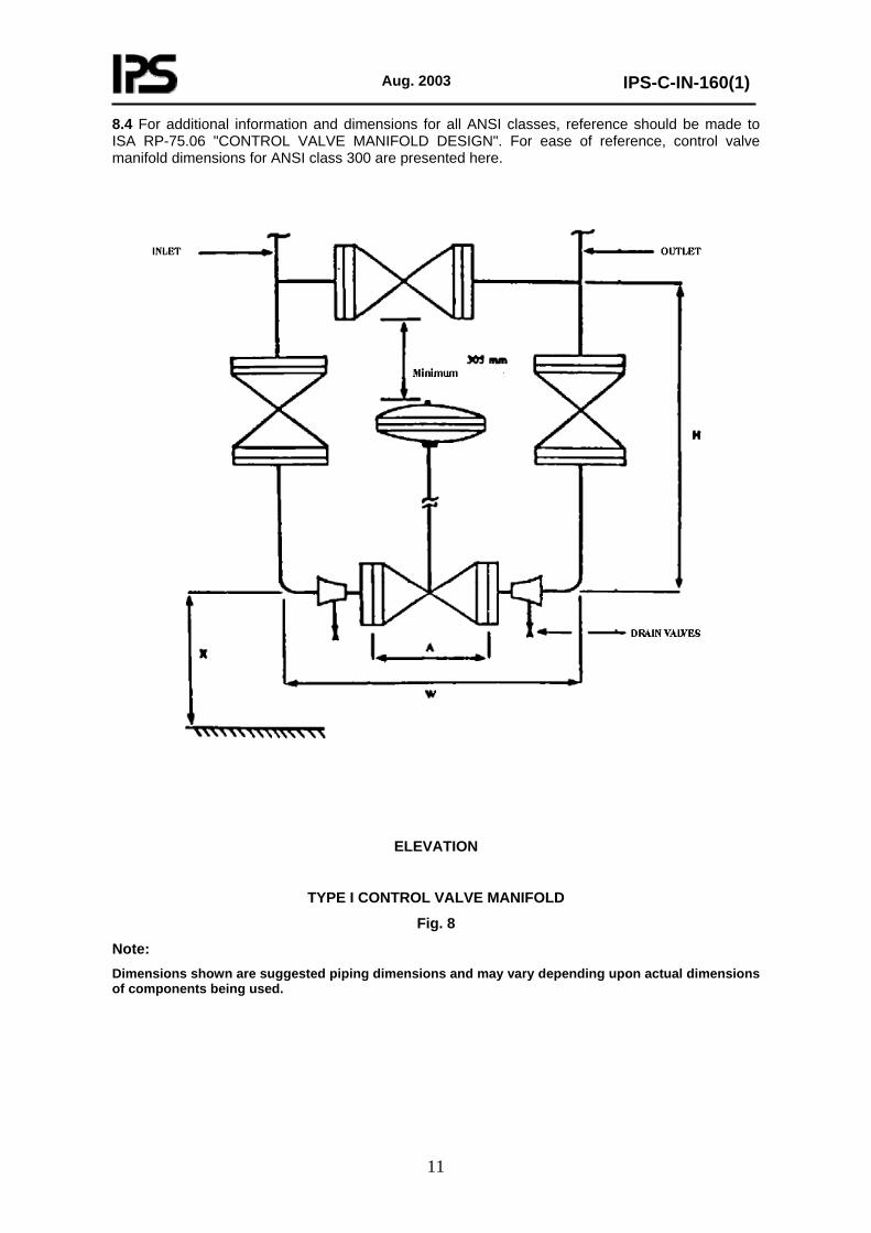
8.4 For additional information and dimensions for all ANSI classes, reference should be made to ISA RP-75.06 "CONTROL VALVE MANIFOLD DESIGN". For ease of reference, control valve manifold dimensions for ANSI class 300 are presented here.
ELEVATION
TYPE I CONTROL VALVE MANIFOLD
Fig. 8
Note: Dimensions shown are suggested piping dimensions and may vary depending upon actual dimensions of components being used.
Aug. 2003
IPS-C-IN-160(1)
12
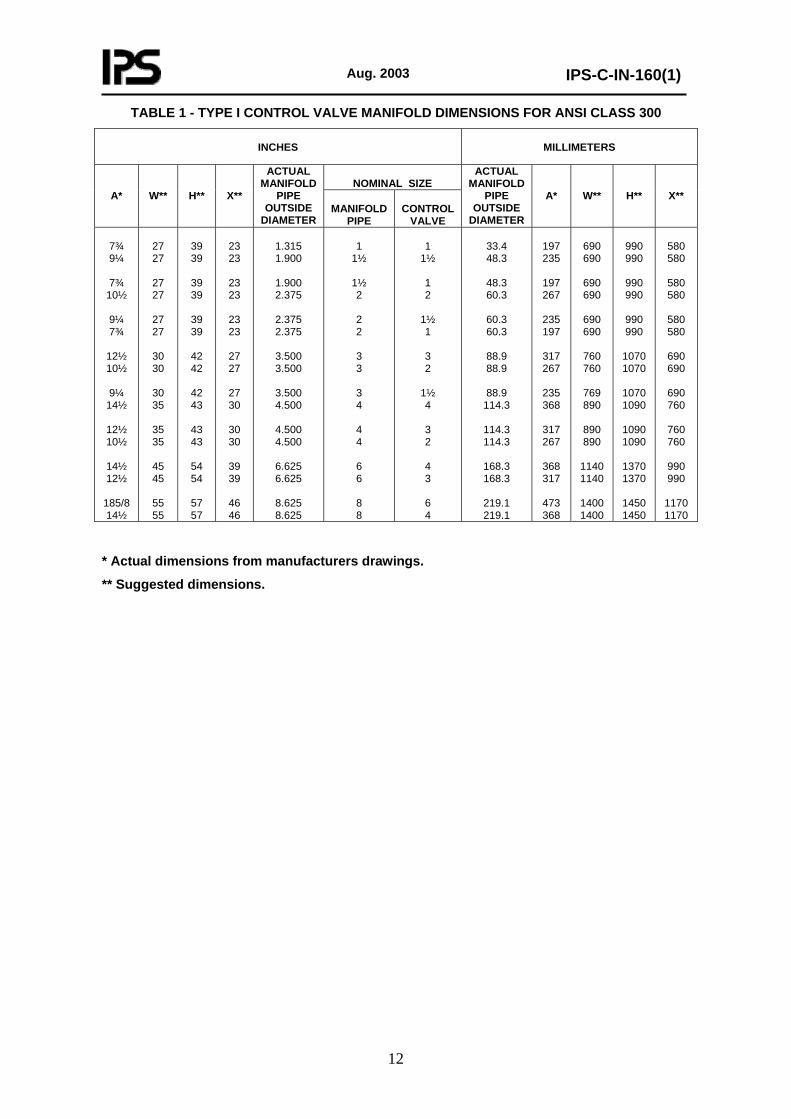
TABLE 1 - TYPE I CONTROL VALVE MANIFOLD DIMENSIONS FOR ANSI CLASS 300
INCHES
MILLIMETERS
NOMINAL SIZE
A*
W**
H**
X**
ACTUAL MANIFOLD
PIPE OUTSIDE
DIAMETER
MANIFOLD
PIPE
CONTROL
VALVE
ACTUAL MANIFOLD
PIPE OUTSIDE
DIAMETER
A*
W**
H**
X**
7¾ 9¼
7¾
10½
9¼ 7¾
12½ 10½
9¼
14½
12½ 10½
14½ 12½
185/8 14½
27 27
27 27
27 27
30 30
30 35
35 35
45 45
55 55
39 39
39 39
39 39
42 42
42 43
43 43
54 54
57 57
23 23
23 23
23 23
27 27
27 30
30 30
39 39
46 46
1.315 1.900
1.900 2.375
2.375 2.375
3.500 3.500
3.500 4.500
4.500 4.500
6.625 6.625
8.625 8.625
1
1½
1½ 2
2 2
3 3
3 4
4 4
6 6
8 8
1
1½
1 2
1½ 1
3 2
1½ 4
3 2
4 3
6 4
33.4 48.3
48.3 60.3
60.3 60.3
88.9 88.9
88.9
114.3
114.3 114.3
168.3 168.3
219.1 219.1
197 235
197 267
235 197
317 267
235 368
317 267
368 317
473 368
690 690
690 690
690 690
760 760
769 890
890 890
1140 1140
1400 1400
990 990
990 990
990 990
1070 1070
1070 1090
1090 1090
1370 1370
1450 1450
580 580
580 580
580 580
690 690
690 760
760 760
990 990
1170 1170
* Actual dimensions from manufacturers drawings.
** Suggested dimensions.

Aug. 2003
IPS-C-IN-160(1)
13
ELEVATION
TYPE II CONTROL VALVE MANIFOLD
Fig. 9
Note: Dimensions shown are suggested piping dimensions and may vary depending upon actual dimensions of components being used.

Aug. 2003
IPS-C-IN-160(1)
14
TABLE 2 - TYPE II CONTROL VALVE MANIFOLD DIMENSIONS FOR ANSI CLASS 300
INCHES
MILLIMETERS
NOMINAL SIZE
A*
W**
H**
X**
ACTUAL MANIFOLD
PIPE OUTSIDE
DIAMETER
MANIFOLD
PIPE
CONTROL
VALVE
ACTUAL MANIFOLD
PIPE OUTSIDE
DIAMETER
A*
W**
H**
X**
7¾ 9¼
7¾
10½
9¼ 7¾
12½ 10½
9¼
14½
12½ 10½
14½ 12½
185/8 14½
44 44
44 44
44 44
48 48
48 56
56 56
70 70
78 78
25 25
25 25
25 25
29 29
29 33
33 33
43 43
50 50
37 37
37 37
37 37
39 39
39 40
40 40
50 50
52 52
1.315 1.900
1.900 2.375
2.375 2.375
3.500 3.500
3.500 4.500
4.500 4.500
6.625 6.625
8.625 8.625
1 1½
1½ 2
2 2
3 3
3 4
4 4
6 6
8 8
1 1½
1 2
1½ 1
3 2
1½ 4
3 2
4 3
6 4
33.4 48.3
48.3 60.3
60.3 60.3
88.9 88.9
88.9
114.3
114.3 114.3
168.3 168.3
219.1 219.1
197 235
197 267
235 197
317 267
235 368
317 267
368 317
473 368
1120 1120
1120 1120
1120 1120
1220 1220
1220 1430
1430 1430
1780 1780
1990 1990
640 640
640 640
640 640
740 740
740 840
840 840
1090 1090
1270 1270
940 940
940 940
940 940
990 990
990
1020
1020 1020
1270 1270
1320 1320
* Actual dimensions from manufacturers drawings.
** Suggested dimensions.

Aug. 2003
IPS-C-IN-160(1)
15
ELEVATION
TYPE III CONTROL VALVE MANIFOLD
Fig. 10 Note:
Dimensions shown are suggested piping dimensions and may vary depending upon actual dimensions of components being used.
Aug. 2003
IPS-C-IN-160(1)
16
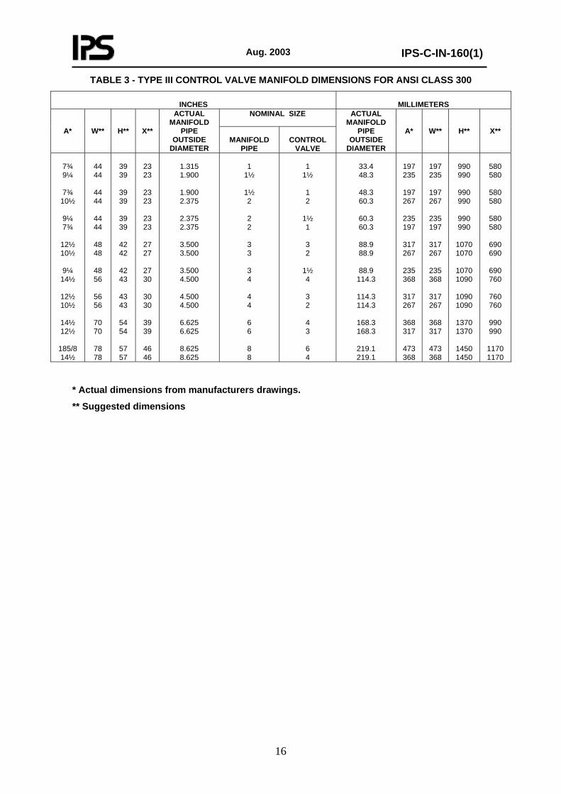
TABLE 3 - TYPE III CONTROL VALVE MANIFOLD DIMENSIONS FOR ANSI CLASS 300
INCHES
MILLIMETERS NOMINAL SIZE
A*
W**
H**
X**
ACTUAL MANIFOLD
PIPE OUTSIDE
DIAMETER
MANIFOLD
PIPE
CONTROL
VALVE
ACTUAL MANIFOLD
PIPE OUTSIDE
DIAMETER
A*
W**
H**
X**
7¾ 9¼
7¾
10½
9¼ 7¾
12½ 10½
9¼
14½
12½ 10½
14½ 12½
185/8 14½
44 44
44 44
44 44
48 48
48 56
56 56
70 70
78 78
39 39
39 39
39 39
42 42
42 43
43 43
54 54
57 57
23 23
23 23
23 23
27 27
27 30
30 30
39 39
46 46
1.315 1.900
1.900 2.375
2.375 2.375
3.500 3.500
3.500 4.500
4.500 4.500
6.625 6.625
8.625 8.625
1
1½
1½ 2
2 2
3 3
3 4
4 4
6 6
8 8
1
1½
1 2
1½ 1
3 2
1½ 4
3 2
4 3
6 4
33.4 48.3
48.3 60.3
60.3 60.3
88.9 88.9
88.9
114.3
114.3 114.3
168.3 168.3
219.1 219.1
197 235
197 267
235 197
317 267
235 368
317 267
368 317
473 368
197 235
197 267
235 197
317 267
235 368
317 267
368 317
473 368
990 990
990 990
990 990
1070 1070
1070 1090
1090 1090
1370 1370
1450 1450
580 580
580 580
580 580
690 690
690 760
760 760
990 990
1170 1170
* Actual dimensions from manufacturers drawings.
** Suggested dimensions

Aug. 2003
IPS-C-IN-160(1)
17
ELEVATION
TYPE IV CONTROL VALVE MANIFOLD
Fig. 11
Note: Dimensions shown are suggested piping dimensions and may vary depending upon actual dimensions of compenents being used.

Aug. 2003
IPS-C-IN-160(1)
18
TABLE 4 - TYPE IV CONTROL VALVE MANIFOLD DIMENSIONS
INCHES
MILLIMETERS
NOMINAL SIZE
A*
W**
H**
X**
ACTUAL MANIFOLD
PIPE OUTSIDE
DIAMETER
MANIFOLD
PIPE
CONTROL
VALVE
ACTUAL MANIFOLD
PIPE OUTSIDE
DIAMETER
A*
W**
H**
X**
7¾ 9¼
7¾
10½
9¼ 7¾
12½ 10½
9¼
14½
12½ 10½
14½ 12½
185/8 14½
58 58
58 58
58 58
67 67
67 74
74 74
97 97
109 109
39 39
39 39
39 39
42 42
42 43
43 43
54 54
57 57
23 23
23 23
23 23
27 27
27 30
30 30
39 39
46 46
1.315 1.900
1.900 2.375
2.375 2.375
3.500 3.500
3.500 4.500
4.500 4.500
6.625 6.625
8.625 8.625
1
1½
1½ 2
2 2
3 3
3 4
4 4
6 6
8 8
1
1½
1 2
1½ 1
3 2
1½ 4
3 2
4 3
6 4
33.4 48.3
48.3 60.3
60.3 60.3
88.9 88.9
88.9
114.3
114.3 114.3
168.3 168.3
219.1 219.1
197 235
197 267
235 197
317 267
235 368
317 267
368 317
473 368
1470 1470
1470 1470
1470 1470
1700 1700
1700 1880
1880 1880
2460 2460
2770 2770
990 990
990 990
990 990
1070 1070
1070 1090
1090 1090
1370 1370
1450 1450
580 580
580 580
580 580
690 690
690 760
760 760
990 990
1170 1170
* Actual dimensions from manufacturers drawings.
** Suggested dimensions.

Aug. 2003
IPS-C-IN-160(1)
19
LEVATION
TYPE V CONTROL VALVE MANIFOLD
Fig. 12
Note: Dimensions shown are suggested piping dimensions and may vary depending upon actual dimensions of components being used.

Aug. 2003
IPS-C-IN-160(1)
20
TABLE 5 - TYPE V CONTROL VALVE MANIFOLD DIMENSIONS FOR ANSI CLASS 300
INCHES
MILLIMETERS
NOMINAL SIZE
A*
W**
H**
X**
ACTUAL MANIFOLD
PIPE OUTSIDE
DIAMETER
MANIFOLD
PIPE
CONTROL
VALVE
ACTUAL MANIFOLD
PIPE OUTSIDE
DIAMETER
A*
W**
H**
X**
7¾ 9¼
7¾
10½
9¼ 7¾
12½ 10½
9¼
14½
12½ 10½
14½ 12½
185/8 14½
44 44
44 44
44 44
48 48
48 56
56 56
70 70
78 78
36 36
36 36
36 36
39 39
39 39
39 39
46 46
50 50
37 37
37 37
37 37
39 39
39 40
40 40
50 50
52 52
1.315 1.900
1.900 2.375
2.375 2.375
3.500 3.500
3.500 4.500
4.500 4.500
6.625 6.625
8.625 8.625
1
1½
1½ 2
2 2
3 3
3 4
4 4
6 6
8 8
1
1½
1 2
1½ 1
3 2
1½ 4
3 2
4 3
6 4
33.4 48.3
48.3 60.3
60.3 60.3
88.9 88.9
88.9
114.3
114.3 114.3
168.3 168.3
219.1 219.1
197 235
197 267
235 197
317 267
235 368
317 267
368 317
473 368
1120 1120
1120 1120
1120 1120
1220 1220
1220 1430
1430 1430
1780 1780
1990 1990
910 910
910 910
910 910
990 990
990 990
990 990
1170 1170
1270 1270
940 940
940 940
940 940
990 990
990
1020
1020 1020
1270 1270
1320 1320
* Actual dimensions from manufacturers drawings.
** Suggested dimensions.
Aug. 2003
IPS-C-IN-160(1)
21
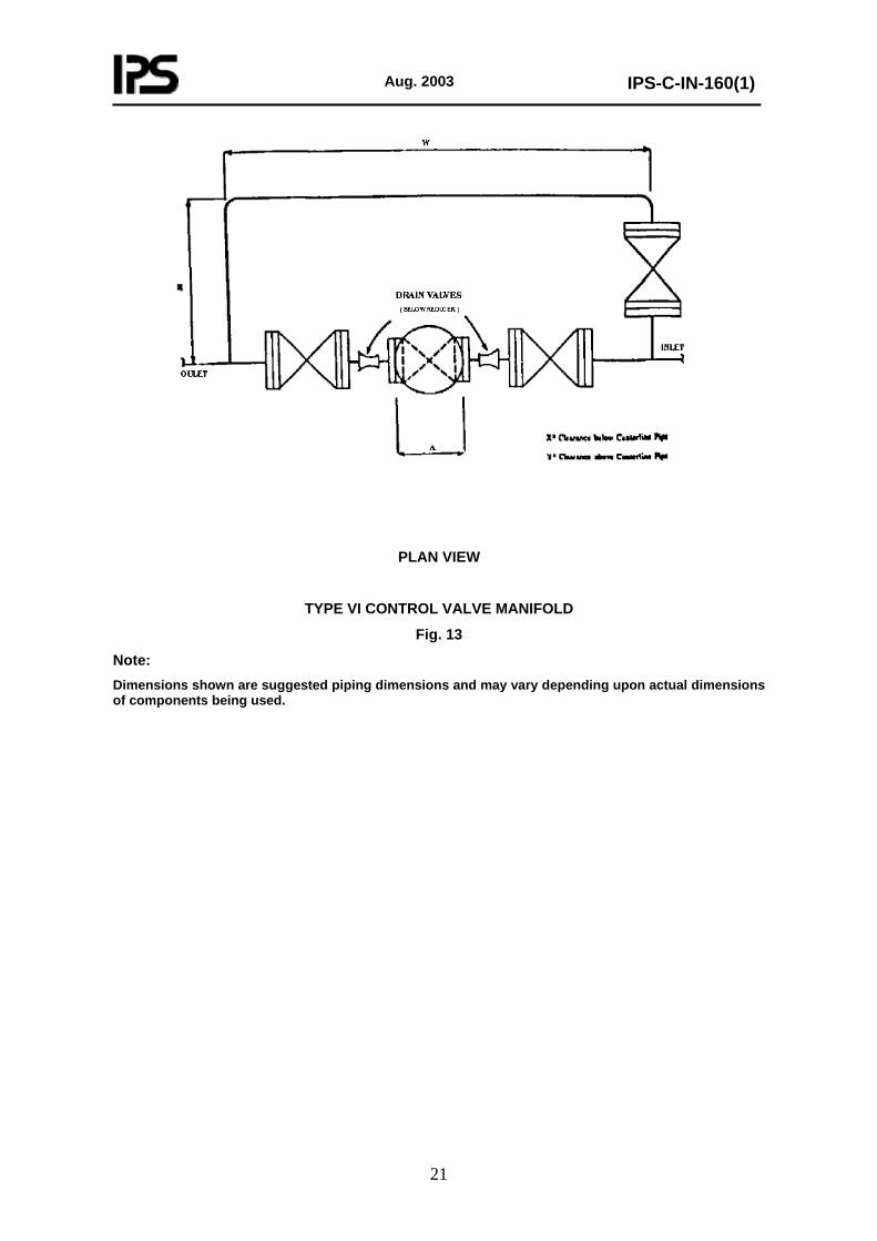
PLAN VIEW
TYPE VI CONTROL VALVE MANIFOLD
Fig. 13
Note: Dimensions shown are suggested piping dimensions and may vary depending upon actual dimensions of components being used.
Aug. 2003
IPS-C-IN-160(1)
22
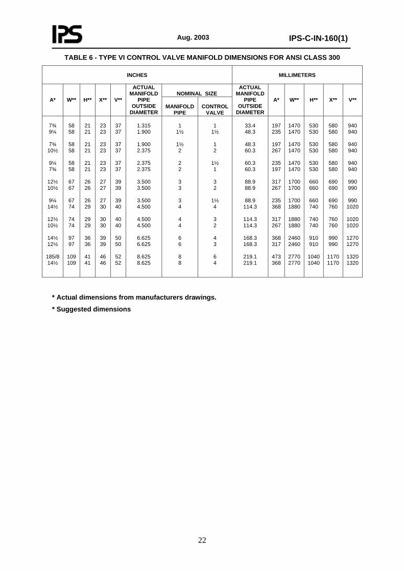
TABLE 6 - TYPE VI CONTROL VALVE MANIFOLD DIMENSIONS FOR ANSI CLASS 300
INCHES
MILLIMETERS
NOMINAL SIZE
A*
W**
H**
X**
V**
ACTUAL MANIFOLD
PIPE OUTSIDE
DIAMETER
MANIFOLD
PIPE
CONTROL
VALVE
ACTUAL MANIFOLD
PIPE OUTSIDE
DIAMETER
A*
W**
H**
X**
V**
7¾ 9¼
7¾
10½
9¼ 7¾
12½ 10½
9¼
14½
12½ 10½
14½ 12½
185/8 14½
58 58
58 58
58 58
67 67
67 74
74 74
97 97
109 109
21 21
21 21
21 21
26 26
26 29
29 29
36 36
41 41
23 23
23 23
23 23
27 27
27 30
30 30
39 39
46 46
37 37
37 37
37 37
39 39
39 40
40 40
50 50
52 52
1.315 1.900
1.900 2.375
2.375 2.375
3.500 3.500
3.500 4.500
4.500 4.500
6.625 6.625
8.625 8.625
1
1½
1½ 2
2 2
3 3
3 4
4 4
6 6
8 8
1
1½
1 2
1½ 1
3 2
1½ 4
3 2
4 3
6 4
33.4 48.3
48.3 60.3
60.3 60.3
88.9 88.9
88.9
114.3
114.3 114.3
168.3 168.3
219.1 219.1
197 235
197 267
235 197
317 267
235 368
317 267
368 317
473 368
1470 1470
1470 1470
1470 1470
1700 1700
1700 1880
1880 1880
2460 2460
2770 2770
530 530
530 530
530 530
660 660
660 740
740 740
910 910
1040 1040
580 580
580 580
580 580
690 690
690 760
760 760
990 990
1170 1170
940 940
940 940
940 940
990 990
990
1020
1020 1020
1270 1270
1320 1320
* Actual dimensions from manufacturers drawings.
* Suggested dimensions
Aug. 2003
IPS-C-IN-160(1)
23
9. SUMMARY OF INSTALLATION PRACTICES
The following detailed items are recommended for consideration in every installation:
9.1 The air supply used to operate pneumatic control valves should be free from oil and moisture.
9.2 Follow the manufacturer’s recommendations for the hydraulic system to power hydraulically driven control valves.
9.3 Follow the manufacturer’s recommendations for the electronic system for electrically or electro-hydraulically driven control valves.
9.4 Inlet piping to control valves with small passage-ways, should be fitted with appropriate filters to eliminate internal valve damage from foreign matter in the piping system.
9.5 Do not put excessive stress on valve bodies when installing in the system. This is particularly important for split body valves.
9.6 Before initial start-up and after a maintenance shut-down, install screens ahead of the control valve to collect pipe scale, rust, and other debris. Whenever possible, the piping system should be fitted with a spool piece and flushed out prior to control valve installation.
9.7 If the valve is to operate in a dusty atmosphere, install a rubber or plastic boot around the stem to protect its polished surface from damage.
9.8 Be sure to follow all of the manufacturer’s instructions for adjustments and switch positions for the accessories. For example, do not leave the valve positioner by-pass switch in the by-pass position.
9.9 If the control valve is to be removed from the system after installation be sure that all block valves are closed and tagged. If the control valve contains damaging fluids or contaminants, it should be tagged accordingly, for proper cleaning, prior to disassembly.
9.10 Be sure the valve is installed with the flow direction arrow in the proper direction. Cases have been reported where the manufacturer furnished a valve with the arrow pointing in the wrong direction.
9.11 Review all of the control valve manufacturer’s specific instructions prior to installation.
10. CONTROL VALVE TEST REQUIREMENTS (GENERAL)
10.1 For testing, all valves shall be completely assembled with packing box fully packed and made up handtight. The valve stem may be lightly lubricated. If the valve is equipped with a positioner, tests shall be performed with the positioner bypassed.
10.2 Control valves shall be checked for smooth stroking and correct input span. Attention shall be given to spring action, split-range operation, reverse-action positioners, etc.
10.3 Packing boxes of all control valves shall be inspected for presence of lantern ring and correct type of packing. Where packing is unsuitable for the intended service, or damaged during inspection, new packing shall be applied.
10.4 Operational Tests shall consist of measuring valve stem position for increasing and decreasing input signals with the positioner by-passed. Performance shall meet the following standards:
a) Stem position error shall not exceed ±5% of rated travel.
b) Hysteresis plus deadband shall not exceed 5% of rated travel.

Aug. 2003
IPS-C-IN-160(1)
24
10.5 Actuators for variable pitch fans on air-cooled heat exchangers shall be tested in situ.
Final adjustment shall be done when plant is in operation:
a) Minimum pitch (usually negative to compensate for heat conduction) shall cause zero air flow.
b) Maximum pitch shall coinside with maximum allowable motor current.
10.6 Cylinder actuators for dampers etc. shall be tested in situ for correct operation.
10.7 The following is considered the minimum inspection criteria for factory assembled control valves:
a) Visual examination, using the assembly drawing;
b) Hydrostatic test;
c) Leakage test;
d) Hysteresis check;
e) Valve-travel check by the operator;
f) Operational check of all accessories limit switches, vlave positioners, etc.
g) Electrical tests (Megger and multimeter) for electrical devices;
h) Packaging and shipping checks to specifications and procedures.
If these tests are properly performed at the factory the receipt inspection will only require visual examination. If these tests were not performed at the factory, or if there is reason to suspect problems, these tests should be performed on site, as required.
10.8 During the start up of any new facilities, care should be taken to keep scale, welding rods, and other foreign material from plugging or damaging control valves. One method is to remove the vlave and substitute a spool piece during flashing operation.

Note to Users
The IPS Standards reflect the views of the Iranian Ministry of Petroleum and are intended for use in the oil and gas production facilities, oil refineries, chemical and petrochemical plants, gas handling and processing installations and other such facilities.
IPS publications are based on internationally acceptable standards and include selections from the options stipulated in the referenced standards. They are also supplemented by additional requirements and/or modifications based on the experience acquired by the Iranian Petroleum Industry and the local market availability. The options which are not specified in the text of the standards are itemized in data sheet/s, so that, the user can select his appropriate preferences therein.
The IPS standards are therefore expected to be sufficiently flexible so that the users can adapt these standards to their requirements. However, they may not cover every requirement or diversity of conditions of each project or work.
For such cases, an addendum to IPS Standard shall be prepared by the user which elaborates the particular requirements of the user. This addendum together with the relevant IPS shall form the job specification for the specific project or work.
The users of IPS publications are therefore requested to send their views and comments, including any addendum prepared for particular cases to the Ministry of Petroleum, Standards and Research Organization. These comments and recommendations will be reviewed by the relevant technical committee and will be incorporated in the formal revision of the relevant IPS. The IPS publications are reviewed and revised approximately every five years.
IRANIAN PETROLEUM STANDARDS
No. 19, Street 14, North kheradmand Karimkhan Avenue, Tehran, Iran Tel: 66153055 88810460 Fax: 88810462 Email: [email protected]