IPMTB-GS - ONE.de · IPMTB-GS Motherboard Reference Guide 5 CPU Socket: Intel LGA1366 Supports:...
30
IPMTB-GS Motherboard Reference Guide
Transcript of IPMTB-GS - ONE.de · IPMTB-GS Motherboard Reference Guide 5 CPU Socket: Intel LGA1366 Supports:...
IPMTB-GSMotherboard Reference Guide
2 IPMTB-GS Motherboard Reference Guide
ContentsContents ....................................................................................2
Notices.......................................................................................3
Safety information ....................................................................4
Specifications summary ..........................................................5
Hardware Installation
1 Before you proceed ............................................................................... 6Package contents .........................................................................6
2 Motherboard layout ............................................................................... 7Top view .......................................................................................7Rear panel connectors .................................................................7
3 Central Processing Unit (CPU) ............................................................. 8Installling the CPU ........................................................................8Installling the CPU heatsink and fan ..........................................10Uninstalling the CPU heatsink and fan ....................................... 11
4 System memory ................................................................................... 12Memory types .............................................................................12Memory module rules and configurations ..................................12Installing a DIMM........................................................................14Removing a DIMM ......................................................................14
5 Expansion slots ................................................................................... 15Installing an expansion card .......................................................15
6 Selectors ............................................................................................... 16
7 Connectors ........................................................................................... 17
8 BIOS Setup reference .......................................................................... 23Main ............................................................................................23Advanced ...................................................................................24Power .........................................................................................25Security ......................................................................................26Boot ............................................................................................28Exit .............................................................................................29
IPMTB-GS Motherboard Reference Guide 3
NoticesFederal Communications Commission StatementThis device complies with Part 15 of the FCC Rules. Operation is subject to the following two conditions:
• This device may not cause harmful interference, and
• This device must accept any interference received including interference that may cause undesired operation.
This equipment has been tested and found to comply with the limits for a Class B digital device, pursuant to Part 15 of the FCC Rules. These limits are designed to provide reasonable protection against harmful interference in a residential installation. This equipment generates, uses and can radiate radio frequency energy and, if not installed and used in accordance with manufacturer’s instructions, may cause harmful interference to radio communications. However, there is no guarantee that interference will not occur in a particular installation. If this equipment does cause harmful interference to radio or television reception, which can be determined by turning the equipment off and on, the user is encouraged to try to correct the interference by one or more of the following measures:
• Reorient or relocate the receiving antenna.
• Increase the separation between the equipment and receiver.
• Connect the equipment to an outlet on a circuit different from that to which the receiver is connected.
• Consult the dealer or an experienced radio/TV technician for help.
NOTE: The use of shielded cables for connection of the monitor to the graphics card is required to assure compliance with FCC regulations. Changes or modifications to this unit not expressly approved by the party responsible for compliance could void the user’s authority to operate this equipment.
Canadian Department of Communications StatementThis digital apparatus does not exceed the Class B limits for radio noise emissions from digital apparatus set out in the Radio Interference Regulations of the Canadian Department of Communications.
This class B digital apparatus complies with Canadian ICES-003.

4 IPMTB-GS Motherboard Reference Guide
Safety informationElectrical safety• To prevent electrical shock hazard, disconnect the power cable from the
electrical outlet before relocating the system.
• When adding or removing devices to or from the system, ensure that the power cables for the devices are unplugged before the signal cables are connected. If possible, disconnect all power cables from the existing system before you add a device.
• Before connecting or removing signal cables from the motherboard, ensure that all power cables are unplugged.
• Seek professional assistance before using an adapter or extension cord. These devices could interrupt the grounding circuit.
• Make sure that your power supply is set to the correct voltage in your area. If you are not sure about the voltage of the electrical outlet you are using, contact your local power company.
• If the power supply is broken, do not try to fix it by yourself. Contact a qualified service technician or your retailer.
Operation safety• Before installing the motherboard and adding devices on it, carefully read all
the manuals that came with the package.
• Before using the product, make sure all cables are correctly connected and the power cables are not damaged. If you detect any damage, contact your dealer immediately.
• To avoid short circuits, keep paper clips, screws, and staples away from connectors, slots, sockets and circuitry.
• Avoid dust, humidity, and temperature extremes. Do not place the product in any area where it may become wet.
• Place the product on a stable surface.
• If you encounter technical problems with the product, contact a qualified service technician or your retailer.
IMPORTANT: This symbol of the crossed out wheeled bin indicates that the product (electrical and electronic equipment) should not be placed in municipal waste. Check local regulations for disposal of electronic products.
IPMTB-GS Motherboard Reference Guide 5
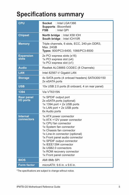
CPU Socket : Intel LGA1366 Supports : Bloomfield FSB : Intel QPI
Chipset North bridge : Intel X58 IOH South bridge : Intel ICH10R
Memory Triple channels, 6 slots, ECC, 240-pin DDR3, Max. 24GB Types: 800/PC3-6400, 1066/PC3-8500
Expansion slots
2x PCI express slots (x16) 1x PCI express slot (x4) 1x PCI express slot (x1)
Audio Realtek ALC888S CODEC (8 Channels)
LAN Intel 82567-V Gigabit LAN
Storage 4x SATA ports (4 onboad headers) SATA300/150 2x eSATA ports
USB 10x USB 2.0 ports (6 onboard, 4 on rear panel)
1394 Via VT6315N
Rear panel I/O ports
1x SPDIF output port 2x eSATA ports (optional) 1x 1394 port + 2x USB ports 1x LAN port + 2x USB ports 6x Audio ports
Internal connectors
1x ATX power connector 1x ATX +12V power connector 1x CPU fan connector 1x System fan connector 1x Chassis fan connector 1x Line-In connector (optional) 1x Front panel audio connector 1x SPDIF output connector 1x IEEE1394 connector 3x USB2.0 connectors 1x ROM recovery connector 1x Front panel connector
BIOS AMI 8Mb SPI
Form factor microATX: 9.6 in. x 9.6 in.
Specifications summary
*The specifications are subject to change without notice.
6 IPMTB-GS Motherboard Reference Guide
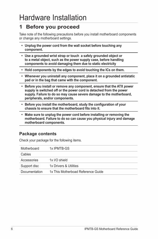
1 Before you proceedTake note of the following precautions before you install motherboard components or change any motherboard settings.
• Unplug the power cord from the wall socket before touching any component.
• Use a grounded wrist strap or touch a safely grounded object or to a metal object, such as the power supply case, before handling components to avoid damaging them due to static electricity
• Hold components by the edges to avoid touching the ICs on them.
• Whenever you uninstall any component, place it on a grounded antistatic pad or in the bag that came with the component.
• Before you install or remove any component, ensure that the ATX power supply is switched off or the power cord is detached from the power supply. Failure to do so may cause severe damage to the motherboard, peripherals, and/or components.
• Before you install the motherboard, study the configuration of your chassis to ensure that the motherboard fits into it.
• Make sure to unplug the power cord before installing or removing the motherboard. Failure to do so can cause you physical injury and damage motherboard components.
Package contents
Check your package for the following items.
Motherboard 1x IPMTB-GS
Cables
Accessories 1x I/O shield
Support disc 1x Drivers & Utilities
Documentation 1x This Motherboad Reference Guide
Hardware Installation
IPMTB-GS Motherboard Reference Guide 7
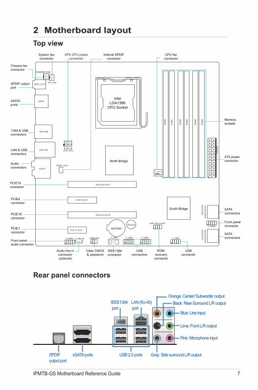
2 Motherboard layout
USBconnectors
Audioconnectors
SATAconnectors
ROM recovery
connector
Front panelconnector
Memorysockets
Front panelaudio connector
CPU fanconnector
PCIE1 connector
PCIE16connector
PCIE4connector
PCIE16connector
ATX powerconnector
ATX CPU powerconnector
ATX_CPU
CHASSIS_FAN
Chassis fanconnector
eSATAports
SPDIF_OUT1
eSATA
System fanconnector
SYS_FAN
1394 & USBconnectors
LAN & USBconnectors
LAN+USB
1394+USB
AUDIO
SPDIF_OUT2
CPU_FAN
F_AUDIO F_LINE_IN
BATTERY
BUZZER
USBconnector
CMOS+PW
IEEE1394connector
F_1394
intelLGA1366
CPU Socket
North Bridge
Clear CMOS& password
Audio line inconnector(optional)
ROM_RECOVERYF_PANEL
F_USB3 F_USB2F_USB4
SA
TA4
(top)
(top)
(bot
tom
)SA
TA3
SA
TA2
(bot
tom
)SA
TA1
ATX
PW
R
SATAconnectors
PCIE X16 SLOT1
PCIE X16 SLOT2
DIM
M2
DIM
M1
DIM
M4
DIM
M3
DIM
M6
DIM
M5
South Bridge
Internal SPDIFconnector
PCIE X1 SLOT
PCIE X4 SLOT
SPDIF outputport
Rear panel connectors
Top view
USB 2.0 ports
IEEE1394 port
SPDIF output port
LAN (RJ-45) port
eSATA ports
Blue: Line input
Black: Rear Surround L/R output
Orange: Center/ Subwoofer output
Lime: Front L/R output
Pink: Microphone input
Gray: Side surround L/R output
8 IPMTB-GS Motherboard Reference Guide
A
B
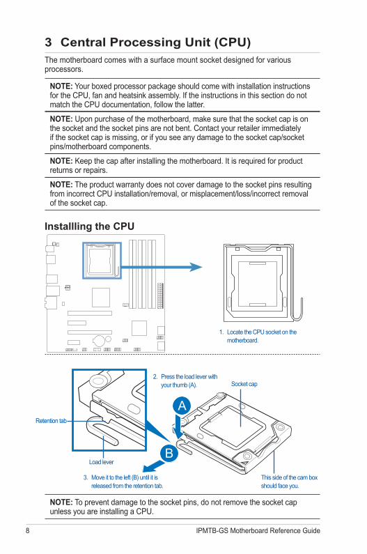
3 Central Processing Unit (CPU)The motherboard comes with a surface mount socket designed for various processors.
NOTE: Your boxed processor package should come with installation instructions for the CPU, fan and heatsink assembly. If the instructions in this section do not match the CPU documentation, follow the latter.
NOTE: Upon purchase of the motherboard, make sure that the socket cap is on the socket and the socket pins are not bent. Contact your retailer immediately if the socket cap is missing, or if you see any damage to the socket cap/socket pins/motherboard components.
NOTE: Keep the cap after installing the motherboard. It is required for product returns or repairs.
NOTE: The product warranty does not cover damage to the socket pins resulting from incorrect CPU installation/removal, or misplacement/loss/incorrect removal of the socket cap.
Installling the CPU
1. Locate the CPU socket on the motherboard.
NOTE: To prevent damage to the socket pins, do not remove the socket cap unless you are installing a CPU.
Socket cap
3. Move it to the left (B) until it is released from the retention tab.
This side of the cam box should face you.
Retention tab
Load lever
2. Press the load lever with your thumb (A).
IPMTB-GS Motherboard Reference Guide 9
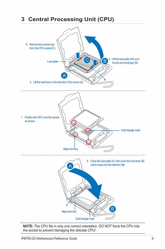
NOTE: The CPU fits in only one correct orientation. DO NOT force the CPU into the socket to prevent damaging the delicate CPU!
Alignment key
Gold triangle mark
7. Position the CPU over the socket as shown.
B
A8. Close the load plate (A), then push the load lever (B)
until it snaps into the retention tab.
Alignment key
Gold triangle mark
4. Lift the load lever in the direction of the arrow (A).
Load plate
A
BC 5. Lift the load plate with your thumb and forefinger (B).
6. Remove the socket cap from the CPU socket (C).
3 Central Processing Unit (CPU)
10 IPMTB-GS Motherboard Reference Guide
3 Central Processing Unit (CPU)
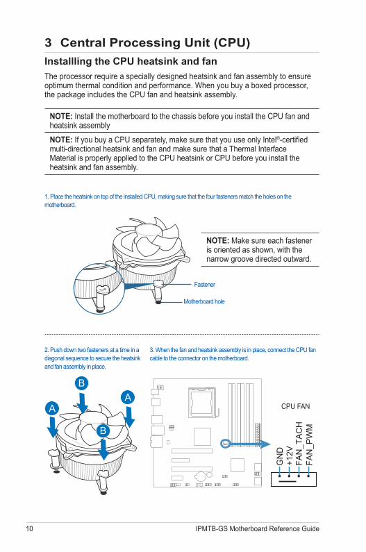
CPU FAN
Installling the CPU heatsink and fan
The processor require a specially designed heatsink and fan assembly to ensure optimum thermal condition and performance. When you buy a boxed processor, the package includes the CPU fan and heatsink assembly.
NOTE: Install the motherboard to the chassis before you install the CPU fan and heatsink assembly
NOTE: If you buy a CPU separately, make sure that you use only Intel®-certified multi-directional heatsink and fan and make sure that a Thermal Interface Material is properly applied to the CPU heatsink or CPU before you install the heatsink and fan assembly.
NOTE: Make sure each fastener is oriented as shown, with the narrow groove directed outward.
Fastener
Motherboard hole
3. When the fan and heatsink assembly is in place, connect the CPU fan cable to the connector on the motherboard.
2. Push down two fasteners at a time in a diagonal sequence to secure the heatsink and fan assembly in place.
A
B
B
A
1. Place the heatsink on top of the installed CPU, making sure that the four fasteners match the holes on the motherboard.
GN
D+1
2VFA
N_T
AC
HFA
N_P
WM
IPMTB-GS Motherboard Reference Guide 11
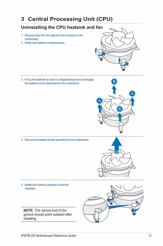
Uninstalling the CPU heatsink and fan
3. Pull up two fasteners at a time in a diagonal sequence to disengage the heatsink and fan assembly from the motherboard.
A
A
B
B
4. Remove the heatsink and fan assembly from the motherboard.
5. Rotate each fastener clockwise to reset the orientation.
NOTE: The narrow end of the groove should point outward after resetting.
1. Disconnect the CPU fan cable from the connector on the motherboard.
2. Rotate each fastener counterclockwise.
3 Central Processing Unit (CPU)
12 IPMTB-GS Motherboard Reference Guide
4 System memory
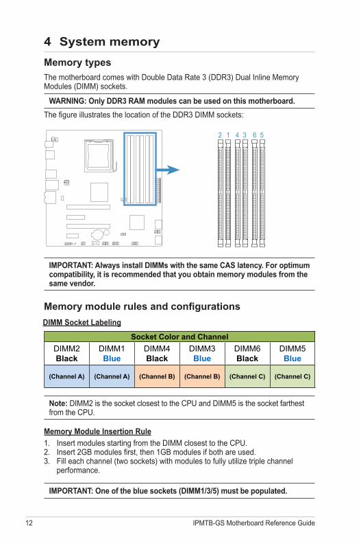
IMPORTANT: Always install DIMMs with the same CAS latency. For optimum compatibility, it is recommended that you obtain memory modules from the same vendor.
Memory types
The motherboard comes with Double Data Rate 3 (DDR3) Dual Inline Memory Modules (DIMM) sockets.
The figure illustrates the location of the DDR3 DIMM sockets:
2 1 4 3 6 5
WARNING: Only DDR3 RAM modules can be used on this motherboard.
Memory module rules and configurations
Note: DIMM2 is the socket closest to the CPU and DIMM5 is the socket farthest from the CPU.
Memory Module Insertion Rule
1. Insert modules starting from the DIMM closest to the CPU.2. Insert 2GB modules first, then 1GB modules if both are used.3. Fill each channel (two sockets) with modules to fully utilize triple channel
performance.
IMPORTANT: One of the blue sockets (DIMM1/3/5) must be populated.
DIMM Socket Labeling
Socket Color and Channel
DIMM2 Black
DIMM1 Blue
DIMM4 Black
DIMM3 Blue
DIMM6 Black
DIMM5 Blue
(Channel A) (Channel A) (Channel B) (Channel B) (Channel C) (Channel C)
IPMTB-GS Motherboard Reference Guide 13
4 System memory
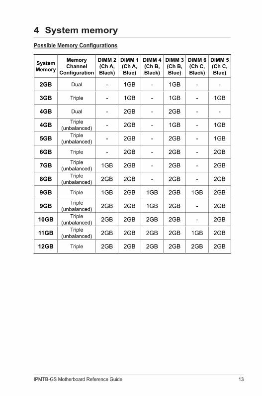
System Memory
Memory Channel
Configuration
DIMM 2 (Ch A, Black)
DIMM 1 (Ch A, Blue)
DIMM 4 (Ch B, Black)
DIMM 3 (Ch B, Blue)
DIMM 6 (Ch C, Black)
DIMM 5 (Ch C, Blue)
2GB Dual - 1GB - 1GB - -
3GB Triple - 1GB - 1GB - 1GB
4GB Dual - 2GB - 2GB - -
4GBTriple
(unbalanced) - 2GB - 1GB - 1GB
5GBTriple
(unbalanced) - 2GB - 2GB - 1GB
6GB Triple - 2GB - 2GB - 2GB
7GBTriple
(unbalanced) 1GB 2GB - 2GB - 2GB
8GBTriple
(unbalanced) 2GB 2GB - 2GB - 2GB
9GB Triple 1GB 2GB 1GB 2GB 1GB 2GB
9GBTriple
(unbalanced) 2GB 2GB 1GB 2GB - 2GB
10GBTriple
(unbalanced) 2GB 2GB 2GB 2GB - 2GB
11GBTriple
(unbalanced) 2GB 2GB 2GB 2GB 1GB 2GB
12GB Triple 2GB 2GB 2GB 2GB 2GB 2GB
Possible Memory Configurations
14 IPMTB-GS Motherboard Reference Guide
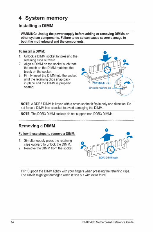
TIP: Support the DIMM lightly with your fingers when pressing the retaining clips. The DIMM might get damaged when it flips out with extra force.
Installing a DIMM
WARNING: Unplug the power supply before adding or removing DIMMs or other system components. Failure to do so can cause severe damage to both the motherboard and the components.
To install a DIMM:
1. Unlock a DIMM socket by pressing the retaining clips outward.
2. Align a DIMM on the socket such that the notch on the DIMM matches the break on the socket.
3. Firmly insert the DIMM into the socket until the retaining clips snap back in place and the DIMM is properly seated.
1. Simultaneously press the retaining clips outward to unlock the DIMM.
2. Remove the DIMM from the socket.
NOTE: A DDR3 DIMM is keyed with a notch so that it fits in only one direction. Do not force a DIMM into a socket to avoid damaging the DIMM.
NOTE: The DDR3 DIMM sockets do not support non-DDR3 DIMMs.
DDR3 DIMM notch
21
1
21
1
3
Unlocked retaining clip
DDR3 DIMM notch
Removing a DIMM
Follow these steps to remove a DIMM:
4 System memory
IPMTB-GS Motherboard Reference Guide 15
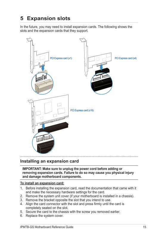
5 Expansion slots
In the future, you may need to install expansion cards. The following shows the slots and the expansion cards that they support.
Installing an expansion card
IMPORTANT: Make sure to unplug the power cord before adding or removing expansion cards. Failure to do so may cause you physical injury and damage motherboard components.
To install an expansion card:
1. Before installing the expansion card, read the documentation that came with it and make the necessary hardware settings for the card.
2. Remove the system unit cover (if your motherboard is installed in a chassis).3. Remove the bracket opposite the slot that you intend to use. 4. Align the card connector with the slot and press firmly until the card is
completely seated on the slot.5. Secure the card to the chassis with the screw you removed earlier.6. Replace the system cover.
PCI Express card (x1) PCI Express card (x4)
PCI Express card (x16)
16 IPMTB-GS Motherboard Reference Guide
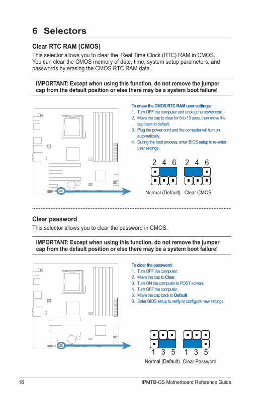
Clear passwordThis selector allows you to clear the password in CMOS.
IMPORTANT: Except when using this function, do not remove the jumper cap from the default position or else there may be a system boot failure!
6 Selectors
To clear the password:1. Turn OFF the computer.2. Move the cap to Clear.3. Turn ON the computer to POST screen.4. Turn OFF the computer.5. Move the cap back to Default.6. Enter BIOS setup to verify or configure new settings.
Clear RTC RAM (CMOS)This selector allows you to clear the Real Time Clock (RTC) RAM in CMOS. You can clear the CMOS memory of date, time, system setup parameters, and passwords by erasing the CMOS RTC RAM data.
IMPORTANT: Except when using this function, do not remove the jumper cap from the default position or else there may be a system boot failure!
To erase the CMOS RTC RAM user settings:1. Turn OFF the computer and unplug the power cord.2. Move the cap to clear for 5 to 10 secs, then move the
cap back to default.3. Plug the power cord and the computer will turn on
automatically.4. During the boot process, enter BIOS setup to re-enter
user settings.
Normal (Default)
Normal (Default)
2 4 6 2 4 6
Clear Password
Clear CMOS
1 3 5 1 3 5
IPMTB-GS Motherboard Reference Guide 17
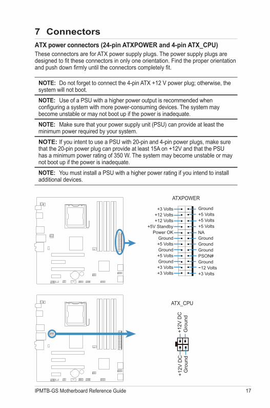
ATX power connectors (24-pin ATXPOWER and 4-pin ATX_CPU)These connectors are for ATX power supply plugs. The power supply plugs are designed to fit these connectors in only one orientation. Find the proper orientation and push down firmly until the connectors completely fit.
NOTE: Do not forget to connect the 4-pin ATX +12 V power plug; otherwise, the system will not boot.
NOTE: Use of a PSU with a higher power output is recommended when configuring a system with more power-consuming devices. The system may become unstable or may not boot up if the power is inadequate.
NOTE: Make sure that your power supply unit (PSU) can provide at least the minimum power required by your system.
NOTE: If you intent to use a PSU with 20-pin and 4-pin power plugs, make sure that the 20-pin power plug can provide at least 15A on +12V and that the PSU has a minimum power rating of 350 W. The system may become unstable or may not boot up if the power is inadequate.
NOTE: You must install a PSU with a higher power rating if you intend to install additional devices.
7 Connectors
ATXPOWER
+3 Volts
Power OKGround
Ground
Ground
Ground GroundGroundGround
GroundPSON#
+5 Volts+5 Volts
+5 VoltsNA
12 Volts
+3 Volts+12 Volts+12 Volts
+5V Standby
+5 Volts
+5 Volts
+3 Volts+3 Volts
ATX_CPU
+12V
DC
Gro
und
Gro
und
+12V
DC
18 IPMTB-GS Motherboard Reference Guide
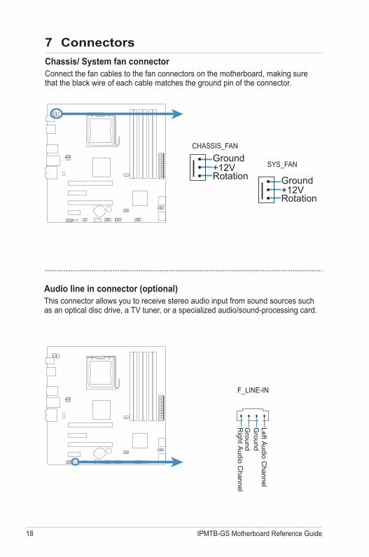
Chassis/ System fan connectorConnect the fan cables to the fan connectors on the motherboard, making sure that the black wire of each cable matches the ground pin of the connector.
7 Connectors
CHASSIS_FAN
Ground+12VRotation
SYS_FAN
Ground+12VRotation
Left Audio C
hannel
Ground
Right A
udio Channel
Ground
CD
F_LINE-IN
Audio line in connector (optional)This connector allows you to receive stereo audio input from sound sources such as an optical disc drive, a TV tuner, or a specialized audio/sound-processing card.
IPMTB-GS Motherboard Reference Guide 19
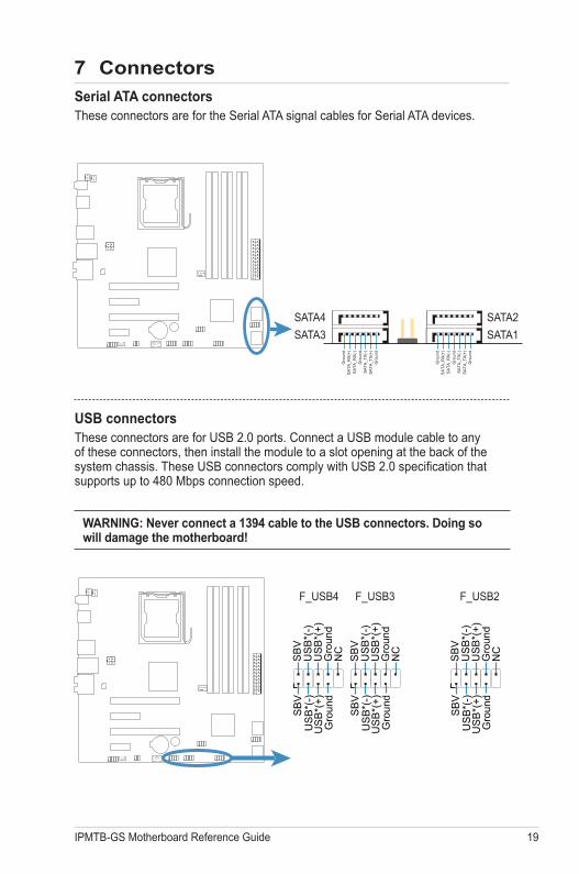
Serial ATA connectorsThese connectors are for the Serial ATA signal cables for Serial ATA devices.
SATA3
SATA4
Gro
und
Gro
und
Gro
und
SA
TA_R
X(+
)S
ATA
_RX
(-)
SA
TA_T
X(-
)S
ATA
_TX
(+)
Gro
und
Gro
und
Gro
und
SA
TA_R
X(+
)S
ATA
_RX
(-)
SA
TA_T
X(-
)S
ATA
_TX
(+)
7 Connectors
USB connectorsThese connectors are for USB 2.0 ports. Connect a USB module cable to any of these connectors, then install the module to a slot opening at the back of the system chassis. These USB connectors comply with USB 2.0 specification that supports up to 480 Mbps connection speed.
WARNING: Never connect a 1394 cable to the USB connectors. Doing so will damage the motherboard!
F_USB4 F_USB3 F_USB2
US
B*(
-)U
SB
*(+)
US
B*(
+)U
SB
*(-)
Gro
und
Gro
und
SB
VS
BV
NC
US
B*(
-)U
SB
*(+)
US
B*(
+)U
SB
*(-)
Gro
und
Gro
und
SB
VS
BV
NC
US
B*(
-)U
SB
*(+)
US
B*(
+)U
SB
*(-)
Gro
und
Gro
und
SB
VS
BV
NC
SATA1
SATA2
20 IPMTB-GS Motherboard Reference Guide
7 Connectors
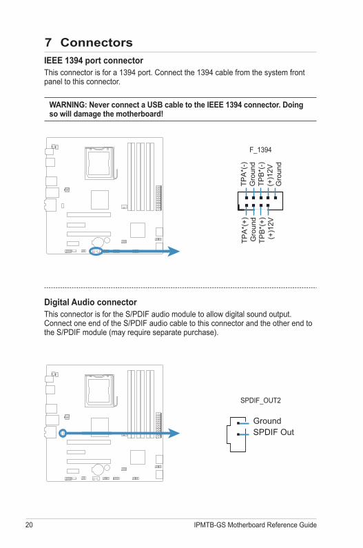
F_1394
IEEE 1394 port connectorThis connector is for a 1394 port. Connect the 1394 cable from the system front panel to this connector.
WARNING: Never connect a USB cable to the IEEE 1394 connector. Doing so will damage the motherboard!
TPA
*(-)
Gro
und
TPB
*(-)
(+)1
2VG
roun
d
TPA
*(+)
Gro
und
TPB
*(+)
(+)1
2V
Digital Audio connectorThis connector is for the S/PDIF audio module to allow digital sound output. Connect one end of the S/PDIF audio cable to this connector and the other end to the S/PDIF module (may require separate purchase).
SPDIF_OUT2
SPDIF OutGround
IPMTB-GS Motherboard Reference Guide 21
7 Connectors
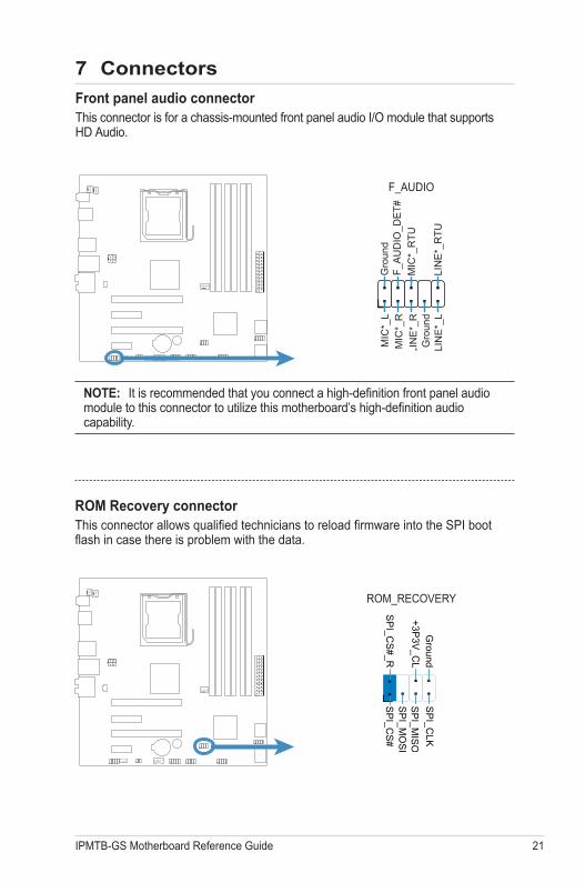
ROM Recovery connectorThis connector allows qualified technicians to reload firmware into the SPI boot flash in case there is problem with the data.
SP
I_CO
NG
round+3P
3V_C
L
SP
I_CS
#_RS
PI_C
S#
SP
I_MO
SI
SP
I_MIS
OS
PI_C
LK
ROM_RECOVERY
Front panel audio connectorThis connector is for a chassis-mounted front panel audio I/O module that supports HD Audio.
NOTE: It is recommended that you connect a high-definition front panel audio module to this connector to utilize this motherboard’s high-definition audio capability.
F_AUDIO
MIC
*_L
MIC
*_R
LIN
E*_
RG
roun
d
Gro
und
LIN
E*_
LLI
NE
*_R
TU
MIC
*_R
TUF_
AU
DIO
_DE
T#
F_AUDIO
22 IPMTB-GS Motherboard Reference Guide
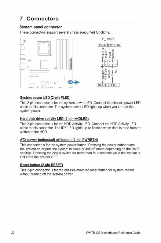
System panel connectorThese connectors support several chassis-mounted functions.
System power LED (2-pin PLED)
This 2-pin connector is for the system power LED. Connect the chassis power LED cable to this connector. The system power LED lights up when you turn on the system power.
Hard disk drive activity LED (2-pin +HDLED)
This 2-pin connector is for the HDD Activity LED. Connect the HDD Activity LED cable to this connector. The IDE LED lights up or flashes when data is read from or written to the HDD.
ATX power button/soft-off button (2-pin PWRBTN)
This connector is for the system power button. Pressing the power button turns the system on or puts the system in sleep or soft-off mode depending on the BIOS settings. Pressing the power switch for more than four seconds while the system is ON turns the system OFF.
Reset button (2-pin RESET)
This 2-pin connector is for the chassis-mounted reset button for system reboot without turning off the system power.
7 Connectors
F_PANEL
Gro
und
HD
LED
(+)
HD
LED
(-)
+HDLED RESET
PW
RG
roun
dR
eset NC
PWRBTNPLED
PLE
D(-
)P
LED
(+)
IPMTB-GS Motherboard Reference Guide 23
8 BIOS Setup reference
BIOS setup programJust when the computer first starts up (before entering your operating system), press and hold the <Del> key to enter the BIOS setup program. (Press <Ctrl+Alt+Delete> to restart if you missed the opportunity.)
NOTE: Default BIOS settings apply for most conditions to ensure optimum performance. If this system becomes unstable after changing any BIOS settings, load the default settings to ensure system compatibility and stability. Find the load default options under the Exit Menu.
IMPORTANT: The BIOS settings are subject to change without notice
BIOS SETUP UTILITY
Main
FieldField
AMIBIOS
Use [ENTER], [TAB]
or [SHIFT-TAB] to
select a field.
Use [+] or [-] to
configure system Time.
Select ScreenSelect ItemChangeSelectGeneral HelpF1Save and ExitF10ExitESC
Tab
Version :01.00
:02/19/09
:1016MB
Build Date
Size
System Overview
System Memory
System TimeSystem Date
[23:15:43][Thu 01/03/2002]
BootSecurity ExitPowerAdvanced
v02.61 (C) Copyright 1985-2008, American Megatrends, Inc.
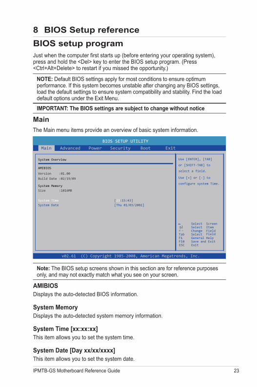
AMIBIOSDisplays the auto-detected BIOS information.
System MemoryDisplays the auto-detected system memory information.
System Time [xx:xx:xx]This item allows you to set the system time.
System Date [Day xx/xx/xxxx]This item allows you to set the system date.
Main
The Main menu items provide an overview of basic system information.
Note: The BIOS setup screens shown in this section are for reference purposes only, and may not exactly match what you see on your screen.
24 IPMTB-GS Motherboard Reference Guide
BIOS SETUP UTILITY
Advanced
F1
Configure CPU.
Select ScreenSelect ItemGo to Sub ScreenGeneral HelpSave and ExitF10ExitESC
Enter
Advanced Settings
Main
CPU ConfigurationSATA Configuration
Hardware Health ConfigurationSpread Spectrum Configuration
Onboard Device Settings
v02.61 (C) Copyright 1985-2008, American Megatrends, Inc.
BootSecurity ExitPower
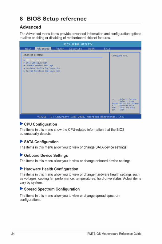
Advanced
The Advanced menu items provide advanced information and configuration options to allow enabling or disabling of motherboard chipset features.
CPU ConfigurationThe items in this menu show the CPU-related information that the BIOS automatically detects.
SATA ConfigurationThe items in this menu allow you to view or change SATA device settings.
Onboard Device SettingsThe items in this menu allow you to view or change onboard device settings.
Hardware Health ConfigurationThe items in this menu allow you to view or change hardware health settings such as voltages, cooling fan performance, temperatures, hard drive status. Actual items vary by system.
Spread Spectrum Configuration
The items in this menu allow you to view or change spread spectrum configurations.
8 BIOS Setup reference
IPMTB-GS Motherboard Reference Guide 25
BIOS SETUP UTILITY
Main BootPower Exit
Select the ACPI
state used for
System Suspend.
F1
Select ScreenSelect ItemGo to Sub ScreenGeneral HelpSave and ExitF10ExitESC
Enter
ACPI Configuration
Suspend mode [Auto]
AC Power Loss
Power On PME# [Disabled][Disabled]
[Power On]
Power On RTC Alarm
SecurityAdvanced
v02.61 (C) Copyright 1985-2008, American Megatrends, Inc.
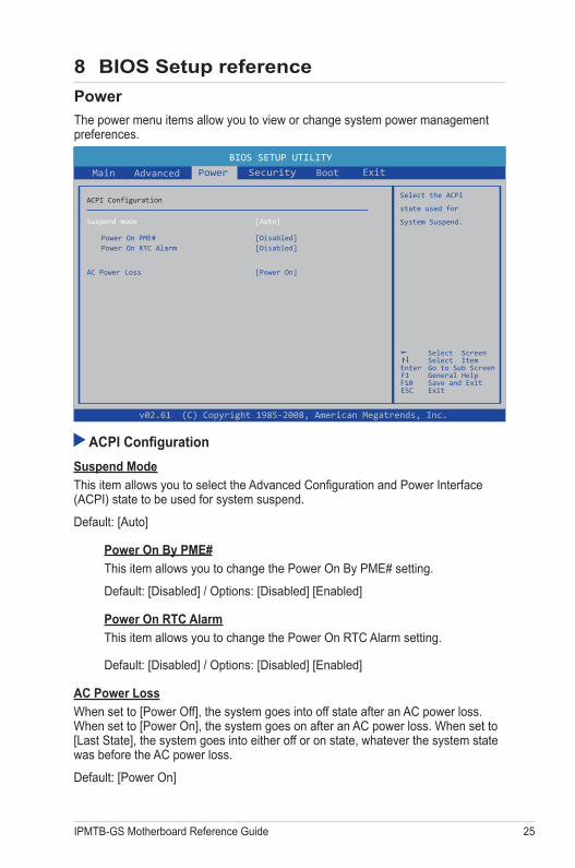
Power
The power menu items allow you to view or change system power management preferences.
ACPI Configuration
Suspend Mode
This item allows you to select the Advanced Configuration and Power Interface (ACPI) state to be used for system suspend.
Default: [Auto]
Power On By PME#
This item allows you to change the Power On By PME# setting.
Default: [Disabled] / Options: [Disabled] [Enabled]
Power On RTC Alarm
This item allows you to change the Power On RTC Alarm setting.
Default: [Disabled] / Options: [Disabled] [Enabled]
AC Power Loss
When set to [Power Off], the system goes into off state after an AC power loss. When set to [Power On], the system goes on after an AC power loss. When set to [Last State], the system goes into either off or on state, whatever the system state was before the AC power loss.
Default: [Power On]
8 BIOS Setup reference
26 IPMTB-GS Motherboard Reference Guide
BIOS SETUP UTILITY
Advanced
F1
Install or Change the
password.
Select ScreenSelect ItemChangeGeneral HelpSave and ExitF10ExitESC
Enter
Security Settings
Main
Supervisor Password
Change Supervisor Password
:Not Installed:Not InstalledUser Password
Change User Password
v02.61 (C) Copyright 1985-2008, American Megatrends, Inc.
Boot ExitPower Security
Security
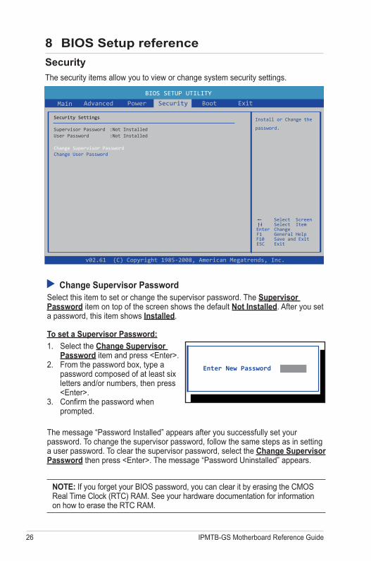
The security items allow you to view or change system security settings.
Enter New Password
Change Supervisor PasswordSelect this item to set or change the supervisor password. The Supervisor Password item on top of the screen shows the default Not Installed. After you set a password, this item shows Installed.
To set a Supervisor Password:
1. Select the Change Supervisor Password item and press <Enter>.
2. From the password box, type a password composed of at least six letters and/or numbers, then press <Enter>.
3. Confirm the password when prompted.
The message “Password Installed” appears after you successfully set your password. To change the supervisor password, follow the same steps as in setting a user password. To clear the supervisor password, select the Change Supervisor Password then press <Enter>. The message “Password Uninstalled” appears.
NOTE: If you forget your BIOS password, you can clear it by erasing the CMOS Real Time Clock (RTC) RAM. See your hardware documentation for information on how to erase the RTC RAM.
8 BIOS Setup reference
IPMTB-GS Motherboard Reference Guide 27
After you have set a supervisor password, the other items appear to allow you to change other security settings.
User Access LevelThis item allows you to select the access restriction to the Setup items. Configuration options: [No Access] [View Only] [Limited] [Full Access]
[No Access] prevents user access to the Setup utility.
[View Only] allows access but does not allow change to any field.
[Limited] allows changes only to selected fields, such as Date and Time.
[Full Access] allows viewing and changing all the fields in the Setup utility.
Change User PasswordSelect this item to set or change the user password. The User Password item on top of the screen shows the default Not Installed. After you set a password, this item shows Installed.
To set a User Password
1. Select the Change User Password item and press <Enter>.2. On the password box that appears, type a password composed of at least six
letters and/or numbers, then press <Enter>. 3. Confirm the password when prompted.
The message “Password Installed” appears after you set your password successfully. To change the user password, follow the same steps as in setting a user password.
Clear User Password
Select this item to clear the user password.
Password Check
When set to [Setup], BIOS checks for user password when accessing the Setup utility. When set to [Always], BIOS checks for user password both when accessing Setup and booting the system.
Default: [Setup] / Options: [Setup] [Always]
Security
8 BIOS Setup reference
28 IPMTB-GS Motherboard Reference Guide
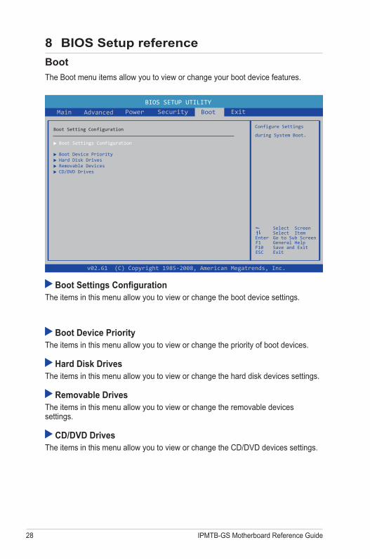
Boot
The Boot menu items allow you to view or change your boot device features.
BIOS SETUP UTILITY
Boot Settings Configuration
Main Boot Exit
Configure Settings
during System Boot.
F1
Select ScreenSelect ItemGo to Sub ScreenGeneral HelpSave and ExitF10ExitESC
Enter
Boot Setting Configuration
SecurityPowerAdvanced
v02.61 (C) Copyright 1985-2008, American Megatrends, Inc.
Boot Device PriorityHard Disk DrivesRemovable DevicesCD/DVD Drives
Boot Settings Configuration The items in this menu allow you to view or change the boot device settings.
Boot Device PriorityThe items in this menu allow you to view or change the priority of boot devices.
Hard Disk DrivesThe items in this menu allow you to view or change the hard disk devices settings.
Removable DrivesThe items in this menu allow you to view or change the removable devices settings.
CD/DVD DrivesThe items in this menu allow you to view or change the CD/DVD devices settings.
8 BIOS Setup reference
IPMTB-GS Motherboard Reference Guide 29
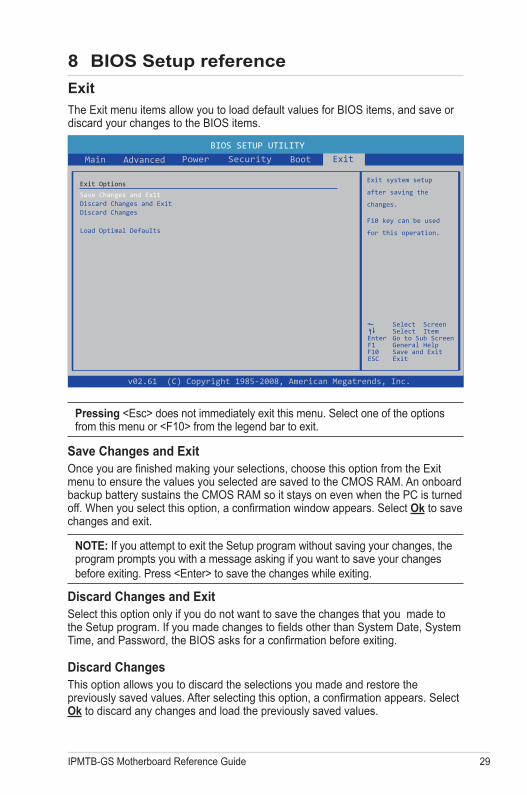
Pressing <Esc> does not immediately exit this menu. Select one of the options from this menu or <F10> from the legend bar to exit.
Save Changes and ExitOnce you are finished making your selections, choose this option from the Exit menu to ensure the values you selected are saved to the CMOS RAM. An onboard backup battery sustains the CMOS RAM so it stays on even when the PC is turned off. When you select this option, a confirmation window appears. Select Ok to save changes and exit.
NOTE: If you attempt to exit the Setup program without saving your changes, the program prompts you with a message asking if you want to save your changes before exiting. Press <Enter> to save the changes while exiting.
Discard Changes and ExitSelect this option only if you do not want to save the changes that you made to the Setup program. If you made changes to fields other than System Date, System Time, and Password, the BIOS asks for a confirmation before exiting.
Discard ChangesThis option allows you to discard the selections you made and restore the previously saved values. After selecting this option, a confirmation appears. Select Ok to discard any changes and load the previously saved values.
BIOS SETUP UTILITY
Main Boot Exit
Exit system setup
after saving the
changes.
F1
Select ScreenSelect ItemGo to Sub ScreenGeneral HelpSave and ExitF10ExitESC
Enter
Exit Options
Save Changes and ExitDiscard Changes and ExitDiscard Changes
Load Optimal DefaultsF10 key can be used
for this operation.
SecurityPowerAdvanced
v02.61 (C) Copyright 1985-2008, American Megatrends, Inc.
Exit
The Exit menu items allow you to load default values for BIOS items, and save or discard your changes to the BIOS items.
8 BIOS Setup reference
30 IPMTB-GS Motherboard Reference Guide
Load Optimal DefaultThis option allows you to load the optimal default values for each of the parameters on the Setup items. When you select this option, a confirmation window appears. Select Yes to load the optimal default values. Select Save Changes and Exit or make other changes before saving.
Exit
8 BIOS Setup reference