
Iowa Culvert Hydraulics Software Version 3 · Introduction: Iowa Culverts Hydraulics Software,...
82
Iowa Culvert Hydraulics Software Version 3.0 Software User’s Manual 2016
Transcript of Iowa Culvert Hydraulics Software Version 3 · Introduction: Iowa Culverts Hydraulics Software,...

Iowa Culvert Hydraulics Software
Version 3.0
Software User’s Manual
2016

2
You can click on an item in the Table of Contents to jump directly to that section.
Table of Contents Introduction: Iowa Culverts Hydraulics Software, Version 3.0 ..................................................................................... 3
Iowa DOT Culvert Program .......................................................................................................................................... 4
Site Identification .......................................................................................................................................................... 5
Design-Q’s ..................................................................................................................................................................... 5
The Iowa Runoff Chart .............................................................................................................................................. 5
Design-Q Table.......................................................................................................................................................... 6
Tailwater ........................................................................................................................................................................ 8
Channel Cross-Section............................................................................................................................................... 8
Rating Curve ............................................................................................................................................................ 11
Q-Depth ................................................................................................................................................................... 12
Culvert Design ............................................................................................................................................................. 13
IDOT Standard Design ............................................................................................................................................ 14
Tapered Inlet Design................................................................................................................................................ 15
Drop Inlet Design .................................................................................................................................................... 18
General Design ........................................................................................................................................................ 24
Erosion ......................................................................................................................................................................... 29
NE Scour Hole Design............................................................................................................................................. 29
NE Plunge Basin Design ......................................................................................................................................... 31
Hec-14 Riprap Basin ............................................................................................................................................... 36
Appendices .................................................................................................................................................................. 42
Appendix A: Hydraulic Design of Highway Culverts, HDS-5 .................................................................................... 42
Appendix B: Copying and Pasting Values .................................................................................................................. 42
Appendix C: The Iowa Runoff Chart .......................................................................................................................... 43
Appendix D: Tailwater Computations ......................................................................................................................... 46
Appendix E: Tapered Inlet Design .............................................................................................................................. 48
Appendix F: Tapered Inlet Calculations ...................................................................................................................... 54
Appendix G: Drop Inlet Design ................................................................................................................................... 56
Appendix H: General Design Inlets Nomenclature ..................................................................................................... 62
Appendix I: Inlet Control............................................................................................................................................. 63
Appendix J: Outlet Control .......................................................................................................................................... 65
Appendix K: Exit Velocity .......................................................................................................................................... 67
Appendix L: IDOT Standard Sizes .............................................................................................................................. 68
Appendix M: NE Scour Hole Design Methodology .................................................................................................... 75
Appendix N: NE Plunge Basin .................................................................................................................................... 77
Appendix O: Hec-14 Riprap Basin .............................................................................................................................. 78

3
Introduction: Iowa Culverts Hydraulics Software, Version 3.0
The Iowa Culvert Hydraulics Software was written to assist Consultants, City, County and State
Engineers with the hydraulic design of culverts in Iowa. The software implements the methods
and standards used by the Iowa Department of Transportation (IDOT) for the hydraulic design of
culverts.
This user manual covers version 3 of the software.
This user manual can be accessed as a pdf file from the software, from the menu item “Help”.
The software incorporates,
Runoff Estimation
Iowa Runoff Chart
Tailwater depth estimation from channel cross-section information
Iowa DOT design methodologies for
Standard designs
Taper Inlets
Drop Inlets
General Culvert Design calculations
The design of energy dissipators for outlet erosion control
NE Scour Hole Design
NE Plunge Basic Design
HEC-14 Riprap Basin Design
Hydraulic calculations are based on the methods in the Hydraulic Design of Highway Culverts,
Hydraulic Design Series 5, from the Federal Highway Administration, September 1985. See
Appendix A for information on how to obtain a copy.
This manual discusses how to use the software, and the assumptions and equations used to
perform the calculations. More detailed information on assumptions and equations are contained
in a series of Appendices.
This software user manual is not a culvert design manual. The software is intended to provide
assistance with the hydraulic design of culverts. Contact your appropriate city, county or IDOT
agency to obtain detailed information on culvert design requirements and methods.
For version 1 of the software there were two versions: one using U.S. units and one using S.I.
units. Generally, designs are done using one set of units or the other, but not both. You can
install both programs (U.S. Units and S.I. Units). They are installed as separate pieces of
software. This manual uses the U.S. units version of the software as the basis for discussion.

4
However, both versions function the same and this manual serves as the user manual for both
versions. Only the units are different, and the units required are prominently displayed. For
version 2.0 of the software only a version using U.S. Units in available.
Version 3.0 of the software uses only U.S. Units.
Iowa DOT Culvert Program
Version 3.0
Software Users Manual
2016
Acknowledgements
The Iowa Highway Research Board and the Iowa Department of Transportation funded the
development of version 1.0 of this software through Research Project TR-447, “A Computer
Program for the Hydraulic Design of Culverts”.
Version 2.0 was funded by the Iowa Highway Research Board and the Iowa Department of
Transportation through Research Project TR-504, “Extensions to the Iowa Culvert Hydraulics
Software – The Design of Energy Dissipators”.
Version 3.0 was funded by the Iowa Highway Research Board and the Iowa Department of
Transportation through Research Project TR-655, “Updating the Iowa Culvert Hydraulics and
Iowa Bridge Backwater Software”.
Dave Claman of the Iowa DOT Office of Bridge & Structures served as the project manager. The
project manager for Digital Control, Inc. was LaDon Jones.
The opinions, findings, and conclusions expressed in this publication are those of the author and
not necessarily those of the Iowa Department of Transportation.
Disclaimer:
Although the Iowa Culvert Hydraulics (Iowa DOT Culvert Program) software and user’s manual
have been carefully prepared and tested, the Iowa Department of Transportation and Digital
Control, Inc. makes no representation or warranty regarding the accuracy, correctness, or
completeness of the computer program or of the information contained in the user’s manual. The
Iowa Department of Transportation and Digital Control, Inc. shall not be liable for any direct,
indirect, consequential, or incidental damages resulting from the use of the software or the
information contained herein.

5
Site Identification
Click “Site” on the main menu, then “Identification”, to activate the “Site Identification” form.
Enter the information, as needed, in the text boxes on the form.
Three of the entries in this form will appear on all printouts from the software. If an entry exists
for “File Number” the information shown at the top of each printout is:
County
File Number
Structure Location (Station)
If an entry does not exist for “File Number” the information shown at the top of each printout is:
County
Project Number
Structure Location (Station)
The information is printed at the top of each printout to help ensure that the printouts can be
associated with the correct project.
When you start a new design project you should fill in the Site Identification information first.
Use the “Print” button to print a copy of the Site Identification information.
Design-Q’s
The Iowa Runoff Chart
Click “Design-Q’s” at the top of the main form, then “Iowa Runoff Chart” to display the “Iowa
Runoff Chart” form. Generally, the Iowa Runoff chart is used if the drainage area contributing to
the culvert inlet is less than two square miles (1280 acres).
For more details on the Iowa Runoff Chart see Appendix C.
Enter the “Drainage Area”, in acres, contributing to the culvert inlet. Again the Iowa Runoff
Chart should only be used for drainage areas of less than about 1280 acres (2 square miles). In
fact, the software limits the maximum Drainage Area value for which Q’s will be computed to
1280 acres.
There are two options for determining the Land Factor (LF). You can select previously defined
descriptions for Land Use and Slope, for which the LF factor has been specified, or you can enter
your own LF factor.

6
To use a specified LF factor select a “Land Use” and “Slope” from the drop-down menus (See
Appendix C for descriptions of Land Use and Slope). The LF factor is automatically set by the
software based on the Land Use and Slope. This would be the usual procedure.
To enter your own LF factor click the “Specify” option button. This will enable two text boxes
where you can enter a description for the Land Use and Slope and type in an LF value. The LF
value must be greater than 0 and 1.
After entering the drainage area and selecting a land use and slope (or entering an LF value)
click the “Compute Q’s” button. This will compute the estimated runoff (Q) for the return
periods shown in the table. The “Chart Q” is the Q from the Iowa Runoff Chart (Appendix C).
The “Chart Q” is not a design flowrate. The design Q’s are shown in the table for the range of
return periods defined for the Iowa Runoff Chart.
The Frequency Factors (FF) shown in the table are adjustment factors associated with the return
periods (see Appendix C).
You can copy a value or values from the table. To copy values, select the values you want to
copy in the table, then right click and select “Copy”.
Design-Q Table
If you are not using the Iowa Runoff Chart, for version 3 of the software you determine your Design
Q’s using methods not included in the software, then enter your design Q’s into the software. The values
entered in the Design Q Table can be copied to other parts of the software (General Culver Design) using
the “Copy Q’s” button on that form.
Click the “Design-Q’s” menu item at the top of the main form, then select “Design Q Table” in the
dropdown. If you have not opened the example problem, you will see the following.
7
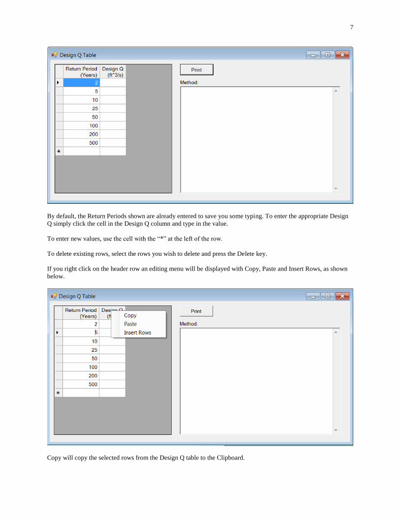
By default, the Return Periods shown are already entered to save you some typing. To enter the appropriate Design
Q simply click the cell in the Design Q column and type in the value.
To enter new values, use the cell with the “*” at the left of the row.
To delete existing rows, select the rows you wish to delete and press the Delete key.
If you right click on the header row an editing menu will be displayed with Copy, Paste and Insert Rows, as shown
below.
Copy will copy the selected rows from the Design Q table to the Clipboard.

8
Paste will paste values from the Clipboard into the table. You can, for example, copy values to the Clipboard using
Excel, then Paste them into the table using this command.
Insert Rows will bring up a dialog box where you can enter the number of empty rows to insert above the currently
selected row.
Tailwater
The tailwater sections of the software provide forms that can be used to estimate stage-discharge
information based on channel cross-section and slope. This is typically used to estimate the
tailwater depth at the culvert outlet due to the hydraulic characteristics of the channel
downstream of the culvert.
Clicking “Tailwater” on the main menu displays the drop-down menu with links to:
Channel Cross-Section
Rating Curve
Q – Depth
Channel Cross-Section
The tailwater sections of the software provide forms that can be used to estimate stage-discharge
information based on channel cross-section and slope. This is typically used to estimate the
tailwater depth at the culvert outlet from the hydraulic characteristics of the channel downstream
of the culvert.
Click “Tailwater”, then “Channel Cross-Section” to bring up the “Tailwater: Channel Cross-
Section” form. You use this form to enter the data describing the stream channel cross-section.
Channel Slope is the slope of the channel bottom in the direction of flow. Always enter the slope
as a positive (>0) value.
Station values must be entered in ascending (increasing) order, although the first station does not
need to be zero, and can be negative.
Elevation is the elevation of the channel bottom at the station.
The first station must have a Manning n value. Manning n values apply from the station they are
entered at until another Manning n value is entered. Hence, you do not need to enter Manning n
values for each station. You need to enter a Manning n for the first station, and then at each
station where there is a change in Manning n value.
Pop Up Edit Menu
If you click the right mouse button in the table a pop up edit menu will be display which allows
you to Copy, Paste, Insert Rows or Clear Values in Selected Cells. You first need to select the

9
area or row(s) in the grid you wish to perform the action on, then click the right mouse button
and select the desired action. To select cells, you press and hold down the left mouse button and
drag the mouse over the area you wish to select, then release the mouse button. If you need to
delete data from the grid, select the information you wish to delete, then press the Delete (Del)
key on your keyboard.
You can also use the keyboard to copy and/or paste data to the grid. To copy data, select the data
you wish to copy and press Ctrl-C. To paste data to the grid, select the area you want to paste the
data to and press Ctrl-V (or use the pop up menu).
See Appendix B for more information on copying and pasting.
Sort
The “Sort” button will sort the cross-section points, by Station value, from the lowest (smallest)
to highest (largest) value. The main value of this button is if you need to add additional data. For
example, if you accidentally left out a station or need to add an additional station, simply add the
information to the end of the information in the grid, then click the “Sort” button. You can also
right click on the grid and select Insert Rows to insert rows where you want to place the new
values.
Over Bank Stations
“Left Over Bank Station” and “Right Over Bank Station” affect the computations of flow area to
the left (Left Over Bank Station) and right (Right Over Bank Station) of the Over Bank Stations.
You are not required to enter over bank stations.
The effect of entering an Over Bank Station is illustrated below. If a left overbank station is
entered then areas to the left of the station (smaller station value) are not included in the flow
area until the water surface elevation is above the elevation at the over bank station. This is
illustrated in the “With Left Over Bank Station” figure. If there is not a left over bank station
then the flow area will be included whenever the water surface elevation is above the channel
bottom, as illustrated by “With No Left Over Bank Station”.
When the water surface elevation is above a high point then all the flow area is included,
regardless of whether or not there is an over bank station, as illustrated in the “Elevation above
over bank” figure below.
If a right over bank station is entered, then the area(s) to the right (higher station) of the right
over bank station are not included in the flow area until the water surface elevation exceeds the
elevation at the right over bank station.

10

11
Print the Cross-Section Data
To print the cross-section data table, click on “Print the Table”.
Plotting the Cross-Section
To plot the cross-section click the “Plot” button. The Manning n values and their range of
coverage are shown at the top of the plot. The channel bottom is shown with a red line. If you
have entered Over Bank Stations their locations are shown with a blue line, with a label of LOB
for Left Over Bank and ROB for Right Over Bank.
Printing the Cross Section: To send a copy of the cross-section to the printer click the “Print the
Plot” button. You need to “Plot” the Cross-Section before you can print it.
Rating Curve
Click “Tailwater”, then “Rating Curve” to bring up the “Tailwater Rating Curve” form. You can
use this form to generate a table and plot of flowrate versus water surface elevation (and depth).
The computations use the channel slope and channel cross-section information you have entered
in the “Tailwater: Channel Cross-Section” form.
The only information you need to enter in this form is the “Step Size”. The flowrates are
computed for elevations from the lowest elevation in the channel cross-section (depth = 0) to the
lowest bank elevation. To determine the lowest bank elevation the software compares the
elevation values at the first station and the last station. The flowrate is computed starting with the
lowest channel elevation and the elevation is incremented by the step size, with computations
continued until the lowest bank elevation is reached.
For example, if you enter a step size of 1 foot the flowrate (Q) will be computed at one-foot
elevation increments of the water surface, starting with the lowest channel elevation.
After entering a step size click the “Compute/Plot Rating Curve” button. This will fill the table
with the results of the computations and also plot flowrate (Q) versus water surface elevation and
water surface depth.
You can send a copy of the table to the printer using the “Print the Table” button, and print a
copy of the plot using the “Print the Plot” button.
To copy values from the table to the clipboard, select the values you want to copy, click the right
mouse button and select “Copy” from the pop up menu.
You can also “Export” the values in the table to a comma delimited text file, using the “Export”
button. This file can be opened in a text editor or imported into Excel.
The computations use the Manning Equation,
12
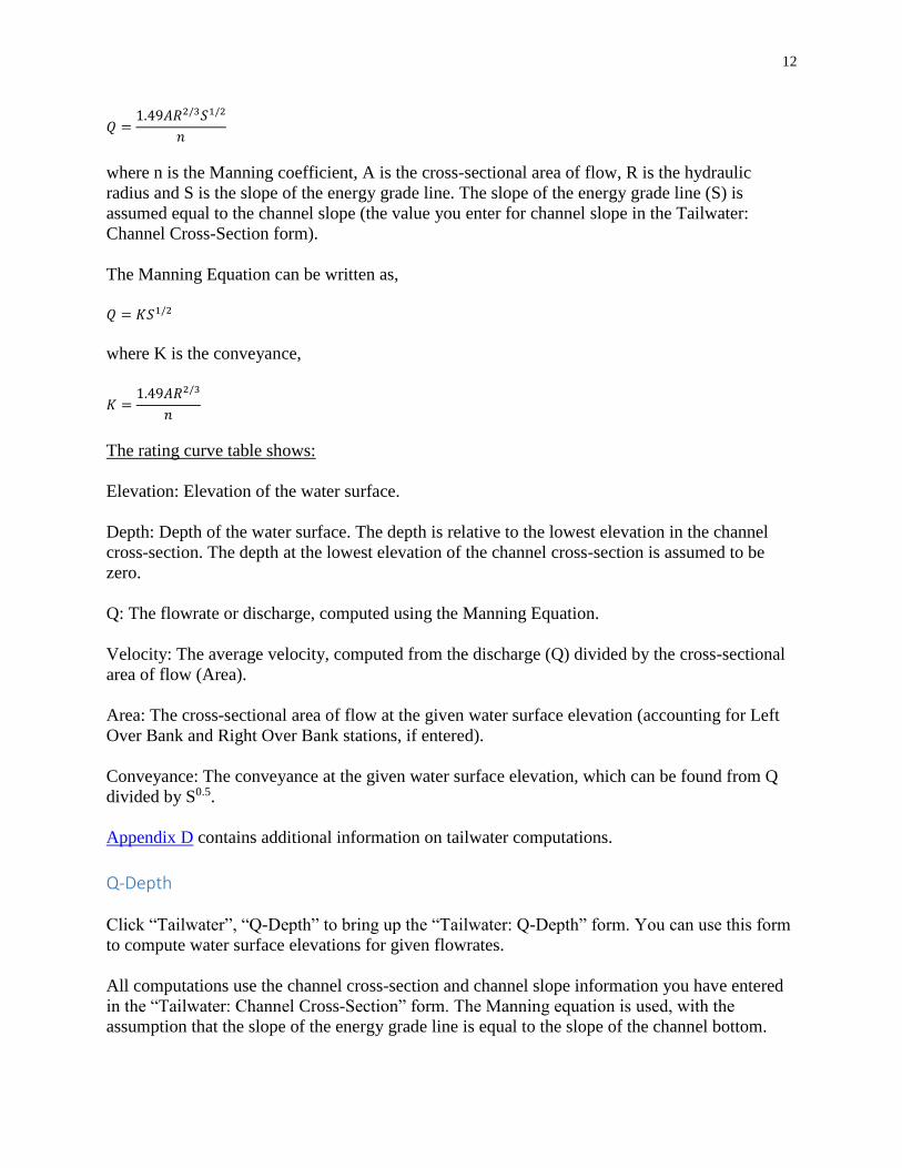
𝑄 =1.49𝐴𝑅2/3𝑆1/2
𝑛
where n is the Manning coefficient, A is the cross-sectional area of flow, R is the hydraulic
radius and S is the slope of the energy grade line. The slope of the energy grade line (S) is
assumed equal to the channel slope (the value you enter for channel slope in the Tailwater:
Channel Cross-Section form).
The Manning Equation can be written as,
𝑄 = 𝐾𝑆1/2
where K is the conveyance,
𝐾 =1.49𝐴𝑅2/3
𝑛
The rating curve table shows:
Elevation: Elevation of the water surface.
Depth: Depth of the water surface. The depth is relative to the lowest elevation in the channel
cross-section. The depth at the lowest elevation of the channel cross-section is assumed to be
zero.
Q: The flowrate or discharge, computed using the Manning Equation.
Velocity: The average velocity, computed from the discharge (Q) divided by the cross-sectional
area of flow (Area).
Area: The cross-sectional area of flow at the given water surface elevation (accounting for Left
Over Bank and Right Over Bank stations, if entered).
Conveyance: The conveyance at the given water surface elevation, which can be found from Q
divided by S0.5.
Appendix D contains additional information on tailwater computations.
Q-Depth
Click “Tailwater”, “Q-Depth” to bring up the “Tailwater: Q-Depth” form. You can use this form
to compute water surface elevations for given flowrates.
All computations use the channel cross-section and channel slope information you have entered
in the “Tailwater: Channel Cross-Section” form. The Manning equation is used, with the
assumption that the slope of the energy grade line is equal to the slope of the channel bottom.

13
Calculator Pad
The grid is a “calculator” pad you can use as needed.
For example, if you enter Q values in the “Q” column, set the option to “Given Q, Find Depth
and Elevation”, then click “Compute”, the software will compute the water surface depth and
elevation for the Q’s in the “Q” column, and display the computed Depths and Elevations in the
appropriate columns.
If the option is set to “Given Depth, Find Q and Elevation”, when “Compute” is clicked the
Depth values will be read from the table, and the computed Q’s and Elevation’s for the given
Depths will be displayed in the table.
If the option is set to “Given Elevation, Find Q and Depth”, , when “Compute” is clicked the
Elevation values will be read from the table, and the computed Q’s and Depths for the given
Elevations will be displayed in the table.
Culvert Design
The Culvert design sections of the software consist of 4 forms for design:
IDOT Standard Design
Tapered Inlet Design
Drop Inlet Design
General Design
These forms are accessed through the “Culvert” item in the main menu at the top of the form.

14
IDOT Standard Design
Click “Culvert”, then “IDOT Standard Design” to display the “IA DOT Standard Designs” form.
This form is used for hydraulic design of culverts, using IDOT standard design methods.
You need to input the design flowrate (Q) and the lower (H-Min.) and upper bound (H-Max.) for
H. H is a design criteria used by the Iowa DOT. H is the height of the headwater above the top of
the culvert at the inlet, as illustrated in the following figures.
Given the value you have input for Q and for the allowable range of H, the software will
compute the value of H for all standard size culverts, and display the culverts that meet the H
range criteria.
By default the software will assume only single barrels. If you wish the software to display the
multiple barrel culverts that meet the H criteria, click on the check box just to the left of “Include
Multiple Barrels”. If the box is not checked, only single barrels are evaluated.
Standard Culverts:
The culvert types and sizes evaluated are IDOT “standard culverts”. Appendix L lists the IDOT
standard sizes.

15
The standard culvert types included in the software are:
Concrete Pipe
Corrugated Metal Pipe
Reinforced Concrete Box
Concrete Pipe Arch
Steel Pipe Arch (2-2/3” by ½” corrugations)
Steel Pipe Arch (3” by 1” or 5” by 1” corrugations)
Inlet Control
The IDOT standard design method is based on evaluating the headwater assuming inlet control
only. That is, in the “IA DOT Standard Designs” form the H value is computed assuming inlet
control. If you wish to check the outlet control headwater elevation for a selected design you can
use the General Design form, discussed later.
The inlet configurations assumed for IA DOT Standard Designs are:
Culvert
Type
Inlet Edge
Description
Chart
No.
Nomograph
Scale
Concrete Box 18 to 33.7 wingwall flare, d=0.083D 9 2
Concrete Pipe Square edge with headwall 1 1
Concrete Pipe
Arch
Square edge with headwall 1 1
Metal Pipe Headwall 2 1
Steel Pipe Arch 90 headwall 34 1
The descriptions, chart numbers and Nomograph scales are from HDS-5. The details for inlet
control, taken from HDS-5, are shown in Appendix I.
Selected Design
Usually a number of possible solutions (culvert type and size) meet the design criteria. You can
identify a culvert type and size as your design using the “Selected Design” column in the tables.
If you click on a row in the “Selected Design” column the row toggle the check symbol in the
column. You can have one selected design for the form.
When you print the IA DOT Standard Designs results the selected design(s), will be indicated on
the printout with “>>>” in the column.
To send a copy of the results to the printer click the “Print” button on the form.
Tapered Inlet Design

16
Click “Culvert”, then “Tapered Inlet Design”. This will bring up the “Tapered Inlet Design”
form. Under inlet control the barrel can convey more flow than the inlet will accept. This
principle can be used to reduce the size of the barrel.
See Appendix E for a discussion of when Tapered Inlets might be used and the equations and
assumptions used to perform the calculations. Appendix F discusses how the software performs
the calculations.
Tapered inlet designs are computed for box culverts only. Inlet control is assumed, and the
following inlet type is assumed,
The inlet configuration assumed for Tapered Inlet Design is:
Culvert
Type
Inlet Edge
Description
Chart No.
Nomograph
Scale
Concrete Box 18 to 33.7 wingwall flare, d=0.083D 9 2
To use an example to illustrate the results, enter the following values:
Q (ft^3/s): 1000
H-Max (ft): 2
H-Min (ft): 0
Check the box to the left of “Include Multiple Barrels” to display feasible multiple barrel
solutions.
Click the “Compute” button. The software shows all the solutions that meet the H criteria for the
given Q.
The columns in the table are:
Number of Barrels: Number of barrels in the solution. The inlet and barrel section are assumed
to have the same number of barrels.
Inlet Width, Inlet Height: The width and height of the culvert inlet.
Inlet H: The height of the headwater at the inlet, measured relative to the top of the inlet (See
IDOT Standard Design for an illustration of H).
Barrel Width, Barrel Height: The width and height of the culvert barrel.
Minimum Z and Minimum L: The minimum drop and length between the culvert inlet and
culvert barrel. That is the Minimum Z and Minimum L for the taper between the inlet and the
barrel. See Appendix E for an illustration.
Barrel Depth (ft): The depth of flow expected in the barrel. The barrel depth is the normal depth
for the barrel, assuming the barrel slope is equal to the minimum barrel slope. The barrel depth is
by default set equal to 90% of the barrel height. However, if this depth exceeds 95% of critical

17
depth for the barrel, then the barrel depth is set equal to 95% of critical depth in order to maintain
super-critical flow in the barrel.
Minimum Barrel Slope: The minimum required barrel slope in order to have super-critical flow
in the barrel. A steeper slope can be used. At the minimum barrel slope the barrel depth is normal
depth.
Selected Design: You can click a row in the “Selected Design” column to identify one of
solutions as your selected design. The selected design is also highlighted on the Tapered Inlet
Design printout.
For the example problem ten possible solutions are shown. For example, you can use a 10 by 10
inlet with an 8 x 10 barrel.
Note that in some cases an inlet may have more than one possible barrel. For the example
problem a 12 foot wide by 8 foot high barrel can be used with either an 8 foot wide by 8 foot
high barrel or a 10 foot wide by 8 foot high barrel.
The example also shows that a twin 10 foot wide by 6 foot high inlet can be used with twin 8
foot wide by 6 foot high barrels.
Computational Procedure
The software computes the feasible solutions using the following procedures;
Possible Inlets: The inlets that meet the H criteria for the given Q are determined, using inlet
control computations (Appendix I). The inlets tested are IA DOT standard size single and twin
concrete box culverts (Appendix L).
Possible Barrels: For each possible inlet potentially feasible barrels are determined. For a barrel
size to be potentially feasible it must have the same height as the inlet and a width that is smaller
than the inlet width. Also, the barrel width must be at least 50% of the inlet width for single
boxes, and at least 60% of the inlet width for twin boxes.
For each possible inlet-barrel combination, the minimum Z-L that produces a depth at the barrel
inlet that does not exceed 90% of the barrel height is determined.
The Z-L combinations tested for single boxes are:
Z (ft) L(ft)
3 10
4 12
5 15
The Z-L combinations test for twin boxes are:
Z (ft) L(ft)
3 15

18
4 20
5 25
For twin boxes, if L = 4(B1-B2) is greater than the L value in the table, the computed L is used.
B1 is the inlet width (one box of the twin box) and B2 is the barrel width (one box of the twin
box). See Appendix E for more information.
All possible combinations may not be feasible with the Z-L combinations tested. For the
example problem a 6 x 8 barrel is possible with a 12 x 8 inlet, but it is not feasible for the
maximum Z value (5 feet). A Z of more than 5 feet would be required to use a 6 x 8 barrel with
the 12 x 8 inlet.
Drop Inlet Design
Select “Culvert”, then “Drop Inlet Design” to show the “Drop Inlet Design” form.
Drop inlets for pipe and box culverts can be beneficial solutions to some drainage and erosion
problems. Hydraulically they are useful when a culvert has limited available head upstream.
Also, they can be used to raise the flowline to create a pond or stop channel erosion upstream.
Appendix G contains additional information on drop inlet design.
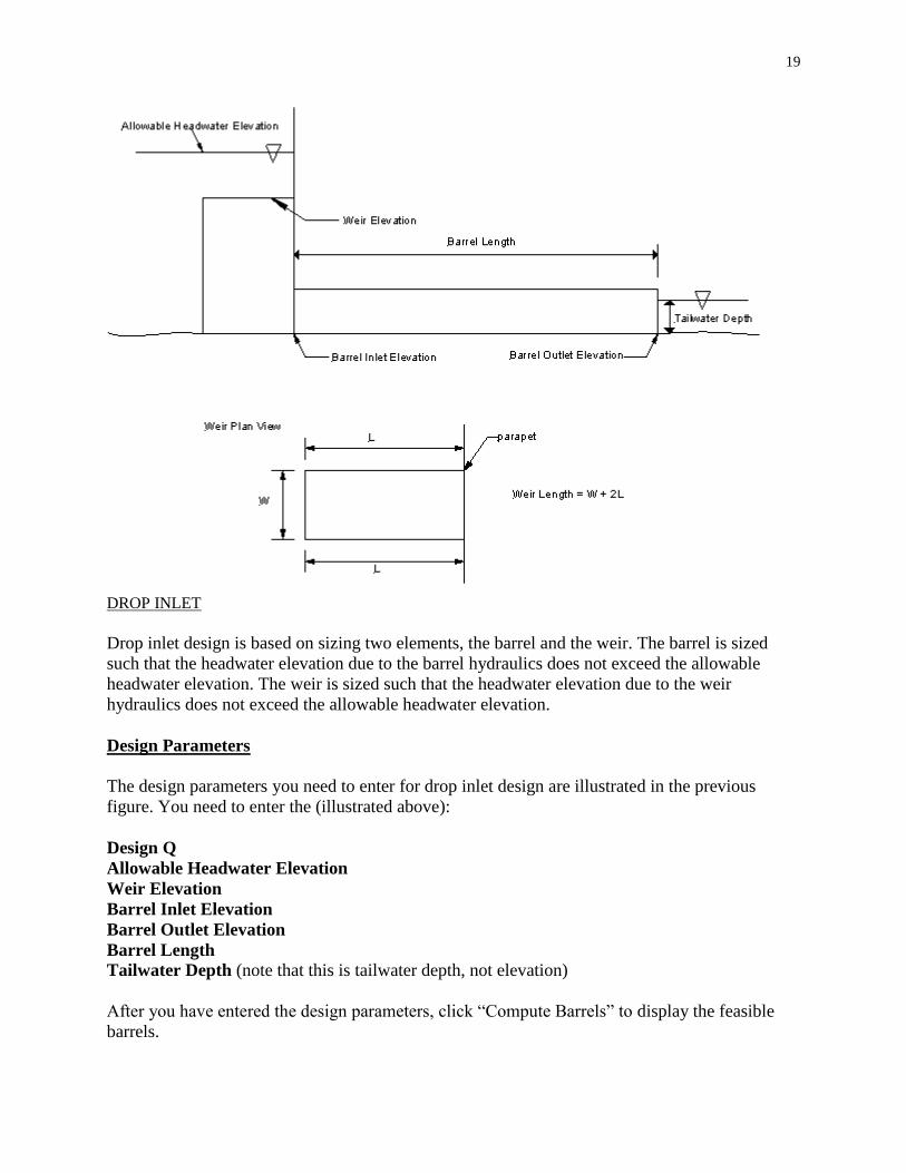
An illustration of a drop inlet is show below.
19
DROP INLET
Drop inlet design is based on sizing two elements, the barrel and the weir. The barrel is sized
such that the headwater elevation due to the barrel hydraulics does not exceed the allowable
headwater elevation. The weir is sized such that the headwater elevation due to the weir
hydraulics does not exceed the allowable headwater elevation.
Design Parameters
The design parameters you need to enter for drop inlet design are illustrated in the previous
figure. You need to enter the (illustrated above):
Design Q
Allowable Headwater Elevation
Weir Elevation
Barrel Inlet Elevation
Barrel Outlet Elevation
Barrel Length
Tailwater Depth (note that this is tailwater depth, not elevation)
After you have entered the design parameters, click “Compute Barrels” to display the feasible
barrels.

20
Barrel Sizing:
The barrel is sized so the headwater elevation due to the barrel hydraulics does not exceed the
allowable headwater elevation. Two barrel types are considered; Concrete Box and Concrete
Pipe. Multiple barrels can be evaluated for Concrete Box (“Include Multiple Barrels (RCB)”),
while only single barrels are evaluated for Concrete Pipe.
The assumed inlet condition for Concrete Box is:
Culvert
Type
Inlet Edge
Description
Chart No.
Nomograph
Scale
Concrete Box 18 to 33.7 wingwall flare, d=0.083D 9 2
The assumed inlet condition for Concrete Pipe is:
Culvert
Type
Inlet Edge
Description
Chart No.
Nomograph
Scale
Concrete Pipe Square edge with headwall 1 1
The columns for the barrel computations are:
The columns for the barrel computations are:
Headwater Elevation: The headwater elevation is the headwater at the inlet, due to the barrel
hydraulics. The headwater is found for inlet control and outlet control, and the maximum is
displayed. Inlet control calculations follow the procedures from HDS-5 (Appendix I). Outlet
control computations also follow the procedures from HDS-5. For outlet control, inlet losses are
assumed to be a combination of entrance losses and bend losses, with a combined coefficient of
1.0 (Appendix G and J).
Head Loss: Head loss is the head loss computed for outlet control, using HDS-5 methods. It
includes inlet losses, barrel friction losses and exit losses. See Appendix G, Appendix J or HDS-
5.
Weir Width: Weir Width is the width of the weir assumed for the culvert barrel. It is simply
assumed to be equal to the width of the culvert barrel (or twice the width of the culvert barrel for
twin barrels).
Weir Length: Using the assumed weir width, the weir length is the minimum length of weir
required in order for the weir to meet the allowable headwater elevation, based on the weir
elevation. The effective weir length is assumed to be,
𝐿𝑤 = 𝑊 + 2𝐿
where Lw is the total effective weir length, W is the width of the weir and L is the length of the
weir. The weir is assumed to have a head wall or parapet, so only three sides are used in
computing the total weir length (see previous Figure or Appendix G).

21
Barrel Sizes Evaluated
For concrete boxes the barrel sizes evaluated are standard IDOT sizes for single and twin barrels.
For concrete pipes the barrel sizes evaluated are standard IDOT sizes, single barrels only. See
Appendix N for a list of standard sizes.
For each size evaluated the headwater elevation, due to the barrel hydraulics, is computed. The
culvert size is included in the barrel table if,
The headwater elevation does not exceed the allowable headwater elevation, and
The headwater depth above the inlet invert is at least 75% of the barrel height.
The lower limit on headwater elevation (75% of barrel height) is included for two reasons. The
first is to not include in the tables sizes that are not likely to be of interest. The second is that the
HDS-5 approximate method is being used for outlet control computations, and HDS-5 notes that
adequate results are obtained down to a headwater of 0.75D, where D is the height of the culvert
barrel. Below a depth of 0.75D the approximate method may be not accurate.
Selected Design
You can designate a selected design(s) by clicking the row for your selected design(s) in the
“Selected Design” column. Selected design(s) will be identified by “>>>” in the printout for drop
inlet design.
Total Weir Length
When you click the “Compute Barrels” button the total length of weir required to meet the
allowable headwater elevation is computed and displayed as “Total Weir Length”. The “Total
Weir Length” is the minimum length of weir required to meet the allowable headwater elevation.
The weir length is computed from,
𝐿𝑤 =𝑄
𝐶𝐻1.5
where Lw is the total linear weir length required to meet the allowable headwater elevation, given
the design Q and Weir elevation. C is the weir coefficient (3.09, English units) and H is the
height of the water surface about the weir elevation. H is set equal to the difference between the
allowable headwater elevation and the weir elevation,
H = Allowable Headwater Elevation – Weir Elevation
The “Weir Length” Columns in the RCB and RCP barrel grids are computed using the “Total
Weir Length” value shown.
Assuming there are three effective sides (see the previous Figure or Appendix G) and the weir is
rectangular, it is assumed that,

22
𝑊 + 2𝐿 = 𝐿𝑤
Where W is the width of the weir and L is the length of the weir.
Solving for L,
𝐿 =𝐿𝑤 −𝑊
2
The computed L is shown in the “Weir Length” column for the barrels.
Rectangular Weir Calculations
In the tables showing the barrel results it is assumed the weir width is equal to the width of the
barrel(s). It may be that you want to determine the length of weir required when the weir width is
not equal to the barrel width.
The “Rectangular Weir Calculations” contains a calculator grid that you can use to determine the
dimensions required for the weir. Use of the weir calculator grid is optional. The Weir calculator
grid assumes a rectangular weir, with three effective sides (see the previous Figure or Appendix
G).
There are 3 computation options.
Option 1: Input Width and Length, Compute Headwater Elevation
This option computes the headwater elevation, given the weir width and length. Perhaps you
have picked a weir width of 6 feet and the minimum required length of weir is 9.67 feet.
However, you decide to use a weir with a width of 6 feet and a length of 10 feet. You can use
this option to estimate the headwater elevation due to the weir.
If you select this option, you need to enter a weir width and length, and the headwater due to the
weir will be computed when you click “Do Weir Computations”.
The computations done for this option are,
𝐿𝑤 = 𝑊 + 2𝐿
Lw is the total effective length of weir, W is the width of the weir (entered by you) and L is the
length (entered by you).
𝐻 = (𝑄
𝐶𝐿𝑤)
11.5
Headwater Elevation = Weir Elevation + H

23
Option 2: Input Width(s), Compute Minimum Weir Length(s)
If you use a weir width that is the same as the width of the barrel(s), this option will give you the
same results as the weir length shown in the tables for the barrels.
You can use this option to compute the minimum length of weir required (assuming a
rectangular weir) to meet the allowable headwater elevations. For example, suppose you are
using a single 6-foot wide box culvert, but the weir width will be 8 feet.
To use this option, click the option button, entered your desired width, then click “Do Weir
Computations”.
The computations for this option are,
H = Allowable Headwater Elevation – Weir Elevation
𝐿𝑤 =𝑄
𝐶𝐻1.5
𝐿 =𝐿𝑤 −𝑊
2
Option 3: Input Length(s), Compute Minimum Weir Width(s)
This option is the same as option 2, except you input a length, and the width of weir required to
meet the allowable headwater elevation is determined.
The computations for this option are,
H = Allowable Headwater Elevation – Weir Elevation
𝐿𝑤 =𝑄
𝐶𝐻1.5
𝑊 = 𝐿𝑤 − 2𝐿
Minimum Total Weir Length
When you click “Do Weir Computations”, the minimum weir length required is computed from,
𝐿𝑤 =𝑄
𝐶𝐻1.5

24
and shown as “Minimum Total Weir Length (ft)”. When you click “Do Weir Computations” the
current values of Q, Allowable Headwater Elevation and Weir Elevation shown in Design
Parameters are used, with
H = Allowable Headwater Elevation – Weir Elevation
This value is shown as a data check. If the barrel results and the weir results have been computed
using the same Q, Allowable Headwater Elevation and Weir Elevation, then the “Total Weir
Length” shown for the Barrels frame will equal the “Minimum Total Weir Length” shown for
the Rectangular Weir Calculations. If they do not match this means the values for Q, Allowable
Headwater Elevation or Weir Elevation used for “ Barrels” and “Do Weir Calculations” do not
match. This can happen, for example, if you changed the Weir elevation, clicked “Do Weir
Calculations” but did not click “Compute Barrels”.
Generally, if you change a design parameter you should click both “Compute Barrels” and “Do
Weir Calculations”. However, “Do Weir Calculations” is only affected by changes in Q,
Allowable Headwater Elevation or Weir Elevation, whereas the barrel computations are affected
by all the parameters.
Non-rectangular Weir
If you are using a non-rectangular weir you can still use the “Total Weir Length” to size your
weir, but you will need to account for the geometry of the weir.
Selected Design
If you wish to identify a particular result in the “Weir” calculator as your design(s) click the row
for your selection(s) in the “Selected Design” column. The selected design(s) will be identified
in the Drop Inlet Design print out by “>>>”.
To print out a copy of the results click the “Print” button.
General Design
Click “Culvert”, then “General Design” to go to the “General Culvert Design” form.
This form will compute the headwater elevation for a particular culvert size and inlet type, under
inlet and outlet control, for a range of Q values.
Design Qs and Tailwater Depth
The grid in the upper left in the “Design Q’s” frame is used to specify design Q’s and Tailwater
Depths. You have several options for entering the data.
Manual:

25
You can enter the values manually by typing them directly into the grid. The required values are
“Design Q” and “TW Depth”. “TW Depth” is the depth of the tailwater above the culvert outlet
invert elevation. If you leave the “TW Depth” blank the tailwater depth is assumed to be 0.
When you click the “Compute” button the culvert hydraulics will be computed for each row that
has “Use” selected (checked), using the Q in the “Design Q” column and the tailwater in the
“TW Depth” column.
If you have entered a channel cross-section and slope into the software (“Tailwater”, “Channel
Cross-Section”) you can have the software compute the tailwater depth. When you click
“Compute Tailwater Depths” the software will use each “Design Q” value to compute a tailwater
depth and insert the value into the grid. If you have not entered a channel cross-section you will
have to enter the tailwater depths manually.
You are not required to enter a return period in the “Return Period” column, but you should enter
a value if you want it to be shown in the results.
To toggle the check in the “Use” column click on a row in the column.
If you are using the Iowa Runoff Chart to estimate your design Q’s you can have the results of
the Iowa Runoff Chart automatically entered into the grid. When you click “Load Iowa Runoff
Chart Q’s” the results in the “Iowa Runoff Chart” form are copied from the “Iowa Runoff Chart”
form to the “Design Q’s” grid.
If you have entered Design Q values in the Design Q Table (“Design Q’s”, then “Design Q
Table” you can have these values copied into the Design Q grid. When you click “Load Design
Q Table Q’s” the values from the Design Q table will be copied to the “Design Q’s” grid. Note
that this is simply a copy operation and you need to entered values into the Design Q Table
before they can be copied.
Again, if you have input a “Channel Cross-Section” under “Tailwater” the tailwater depths for
the values in the “Design Q” column can be computed by clicking “Compute Tailwater Depths”.
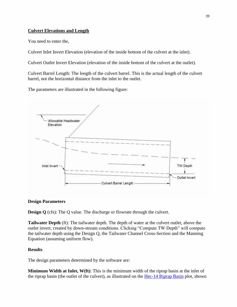
Culvert Elevations and Length
You need to enter the,
Culvert “Inlet Invert Elevation” (elevation of the inside bottom of the culvert at the inlet).
Culvert “Outlet Invert Elevation” (elevation of the inside bottom of the culvert at the outlet).
Culvert Barrel Length: The length of the culvert barrel. This is the actual length of the culvert
barrel, not the horizontal distance from the inlet to the outlet.
Allowable Headwater Elevation: The allowable headwater elevation for your design. This value
is optional. However, if you enter an allowable headwater elevation the computed headwater
elevation will be compared to the allowable headwater elevation and if the computed headwater
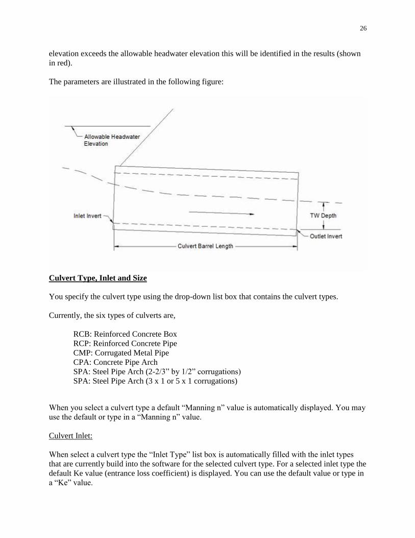
26
elevation exceeds the allowable headwater elevation this will be identified in the results (shown
in red).
The parameters are illustrated in the following figure:
Culvert Type, Inlet and Size
You specify the culvert type using the drop-down list box that contains the culvert types.
Currently, the six types of culverts are,
RCB: Reinforced Concrete Box
RCP: Reinforced Concrete Pipe
CMP: Corrugated Metal Pipe
CPA: Concrete Pipe Arch
SPA: Steel Pipe Arch (2-2/3” by 1/2” corrugations)
SPA: Steel Pipe Arch (3 x 1 or 5 x 1 corrugations)
When you select a culvert type a default “Manning n” value is automatically displayed. You may
use the default or type in a “Manning n” value.
Culvert Inlet:
When select a culvert type the “Inlet Type” list box is automatically filled with the inlet types
that are currently build into the software for the selected culvert type. For a selected inlet type the
default Ke value (entrance loss coefficient) is displayed. You can use the default value or type in
a “Ke” value.

27
Selecting a Size
You can specify the culvert size two ways; select a standard size or type in the dimensions.
Standard Size Selection
When you select a “Culvert Type” the available standard sizes are automatically displayed in the
drop-down list box beneath “IDOT Standard Sizes”. You can scroll the list box to select a size
and number of barrels.
Entering a Barrel Size
If you wish to enter a size, click the radio button to the left of “Enter Barrel Size”. This will
enable text boxes where you can type in the dimension(s) of the culvert barrel and select the
number of barrels.
Culvert Hydraulics
When you click “Compute” the software will compute and display the culvert hydraulic results
for the current design information. The results will be shown for each “Design Q” value that has
“Use” checked. When you click “Compute” the current settings for “Culvert Type”, “Inlet
Type”, “Manning n”, “Ke”, Size, etc., are used in the computations.
Important Note: If you change any design values or parameters you will need to click “Compute”
to update the results to reflect the current design parameters.
The columns in the “Culvert Hydraulics” grid contain the following information:
Return Period: This is simply a copy of the return period value in the “Design Q’s” table.
Q: The Q value. The discharge or flowrate through the culvert. Read from the “Design Q”
column in the “Design Q’s” table.
TW: The tailwater depth. The depth of water at the culvert outlet, above the outlet invert, created
by down-stream conditions. Read from the “TW Depth” column in the “Design Q’s” table.
HW Elev.: The headwater elevation at the culvert inlet. This is the larger of the headwater
elevations computed assuming inlet control and outlet control. If you have entered an allowable
headwater elevation and the computed headwater elevation is above the allowable headwater
elevation the value in this column is shown in red.
HW H: The height of the headwater above the top of the culvert, at the inlet. This is the larger of
the headwater H values from inlet control and outlet control.

28
Exit Velocity: An estimate of the velocity in the culvert barrel at the outlet. The exit velocity is
estimated for inlet control and outlet control and this is the larger of the two values.
I.C. HW: The inlet control headwater elevation. The headwater elevation at the culvert inlet
assuming the culvert is operating under inlet control. Appendix I describes the equations and
assumptions for inlet control.
I.C. H: The inlet control headwater H. The height of the headwater above the top of the culvert
barrel, at the inlet, assuming the culvert is operating under inlet control.
O.C. HW: The outlet control headwater elevation. The headwater elevation at the culvert inlet
assuming the culvert is operating under outlet control. Appendix J describes the equations and
assumptions for outlet control.
O.C. H: The outlet control headwater H. The height of the headwater above the top of the culvert
barrel, at the inlet, assuming the culvert is operating under outlet control.
Exit Velocity I.C.: An estimate of the velocity in the culvert barrel, at the outlet, assuming the
culvert is operating under inlet control. Under inlet control it is assumed the depth in the barrel at
the outlet is normal depth. See Appendix K for more information on exit velocity estimation.
Exit Velocity O.C.: An estimate of the velocity in the culvert barrel, at the outlet, assuming the
culvert is operating under outlet control. See Appendix K for more information on exit velocity
estimation.
Crit. Depth: The critical depth in the barrel, for the given Q, barrel size and barrel geometry. If
the computed critical depth is greater than the top of the culvert the critical depth is set equal to
the height of the culvert barrel.
Normal Depth: The normal depth for the culvert barrel. Computed using the Manning equation
and assuming the slope of the energy grade line is equal to the slope of the culvert barrel.
If the culvert is horizontal or has an adverse slope normal depth is not defined. In this situation
the normal depth is shown as “Undefined(1)”.
If the maximum Q that can by conveyed by the culvert under open channel flow conditions is
less than the Design Q this is shown as “Undefined(2)” in the normal depth column. In this
situation, normal depth does not exist for the Q, or the barrel would be flowing full (pressure
flow) at normal depth.
Hydraulic Slope: The hydraulic slope, as defined by steady open channel hydraulics.
Steep: normal depth < critical depth
Mild: normal depth > critical depth
Critical: normal depth = critical depth
Horizontal: Culvert barrel slope is zero. Inlet invert elevation = Outlet invert elevation
Adverse: Culvert barrel elevation increases from inlet to outlet.

29
Inlet invert elevation < Outlet invert elevation
Undefined: The slope is not horizontal or adverse, and normal depth is not defined.
To send a copy of the results to the printer, click the “Print” button.
Erosion
NE Scour Hole Design
Click “Erosion”, then “NE Scour Hole Design” to activate the “NE Scour Hole Design” form.
This form computes the dimensions and riprap size and thickness for erosion control using a
method from the Nebraska (NE) Department of Roads.
The Nebraska (NE) scour hole design methodology and the following discussion is taken from
the Nebraska Department of Roads, Roadway Design Manual, chapter Five: Erosion and
Sedimentation Control, with reference to 5.5.27.1 Scour Hole.
A scour hole is a preformed excavated hole or depression which is lined with riprap of a stable
size to prevent scouring. The depression provides both vertical and lateral expansion downstream
of the culvert outlet to permit dissipation of excessive energy. A significant reduction in the size
of the riprap stone is achieved by the excavation.
Two types of preformed scour holes can be constructed. The first type of scour hole is depressed
one-half of the culvert diameter (or span). The second type is depressed the full culvert diameter
(or span). The design of preformed scour holes is based upon research conducted by the U.S.
Army Corps of Engineers.
The empirical equations developed for the hydraulic design of preformed scour holes are
presented in Appendix M. Equations are applicable to both circular and rectangular culverts full
or partly full.
To use the form you need to enter the:
Design Q (cfs)
Tailwater Depth (ft):
The tailwater depth at the culvert outlet. Note that this is the depth
above the outlet invert.
Culvert Diameter or Span (ft):
For a circular culvert enter the diameter, otherwise enter the culvert span. The span to be
entered for multiple barrels is not covered in the Nebraska documentation, but it is

30
recommended you enter the total maximum span covered by the culverts. For example,
for twin 6 foot diameter circular pipes laid side by side, enter a value of 12 feet.
The “Compute TW Depth” button will compute the estimated tailwater depth using the Design
Q, the Tailwater Channel Cross-Section and the Manning Equation and insert the computed
value as the Tailwater Depth.
Click the “Compute” button to have the design values displayed. The results for 2 situations are
shown:
The dimensions and riprap size for a scour hole with a depression of ½ the culvert span, and the
dimensions and riprap size for a scour hole with a depression equal to the culvert span.
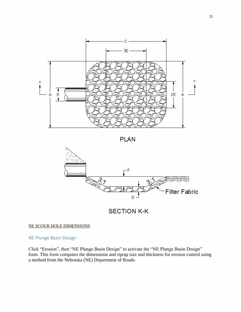
The dimensions, A, C, E and F, along with the riprap thickness, D, are illustrated on the NE
Scour Hole Plot, shown below.
Riprap Size
The “Calculated Riprap Size, D-50, (ft)” is the minimum average stone diameter required for the
scour hole. The “Recommended Riprap Size, D-50” is either Class E or Class B. If the
“Calculated Riprap Size, D-50, (ft)” is <= 1.2 feet, class E is recommended, otherwise Class B is
recommended.
Riprap Thickness
The “Calculated Riprap Thickness, D (ft)” is twice the “Calculated Riprap Size, D-50, (ft)”.
If the recommended riprap size is Class E, the “Recommended Riprap Thickness, D (ft)” is the
larger of the calculated riprap size or 2.0 feet. If the recommended riprap size is Class B, the
“Recommended Riprap Thickness, D (ft)” is the larger of the calculated riprap size or 3.0 feet.
31
NE SCOUR HOLE DIMENSIONS
NE Plunge Basin Design
Click “Erosion”, then “NE Plunge Basin Design” to activate the “NE Plunge Basin Design”
form. This form computes the dimensions and riprap size and thickness for erosion control using
a method from the Nebraska (NE) Department of Roads.

32
The Nebraska (NE) plunge hole design methodology and the following discussion is taken from
the Nebraska Department of Roads, Roadway Design Manual, chapter Five: Erosion and
Sedimentation Control, with reference to 5.5.27.2 Plunge Basin.
The dimensions and layout of the Plunge Basin are illustrated on the NE Plunge Basin Plot,
shown below. The plunge basin should only be used where flows issue from a freely discharging
pipe, and the water jet subsequently discharges into the air and then plunges downward into the
basin. If the angle of impart is too flat, the jet will ride across the surface of the basin at high
velocity causing waves and eddies in the side slopes. Exit velocities will subsequently be high. A
deflector bucket is typically constructed at the outlet of the culvert if a plunge basin will be
installed downstream.
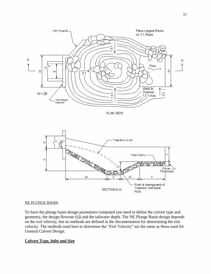
33
NE PLUNGE BASIN
To have the plunge basin design parameters computed you need to define the culvert type and
geometry, the design flowrate (Q) and the tailwater depth. The NE Plunge Basin design depends
on the exit velocity, but no methods are defined in the documentation for determining the exit
velocity. The methods used here to determine the “Exit Velocity” are the same as those used for
General Culvert Design.
Culvert Type, Inlet and Size

34
The “Culvert Type, Inlet and Size” frame is where you specify the culvert information. You
specify the culvert type using the drop-down list box to the right of “Culvert Type”.
Currently, the six types of culverts are,
RCB: Reinforced Concrete Box
RCP: Reinforced Concrete Pipe
CMP: Corrugated Metal Pipe
CPA: Concrete Pipe Arch
SPA: Steel Pipe Arch (2-2/3” by 1/2” corrugations)
SPA: Steel Pipe Arch (3 X 1 or 5 X 1 corrugations)
When you select a culvert type a default “Manning n” value is automatically displayed. You may
use the default or type in a “Manning n” value.
Culvert Inlet:
When you select a culvert type the “Inlet Type” list box is automatically filled with the inlet
types that are currently built into the software for the selected culvert type. For a selected inlet
type the default Ke value (entrance loss coefficient) is displayed. You can use the default value
or type in a “Ke” value.
Each culvert type – inlet combination has associated with it the coefficients used for inlet control
computations. These coefficients are stored internally and are not displayed on the form.
Appendix I contains a list of the inlet control coefficients.
Selecting a Size
You can specify the culvert size two ways; select a standard size or type in the dimensions.
Standard Size Selection
When you select a “Culvert Type” the available standard sizes are automatically displayed in the
drop-down list box beneath “IDOT Standard Sizes”. You can scroll the list box to select a size
and number of barrels.
Entering a Barrel Size
If you wish to enter a size click “Enter Barrel Size”, or click the radio button to the left of “Enter
Barrel Size”. This will enable text boxes where you can type in the dimension(s) of the culvert
barrel and select the number of barrels.
Culvert Elevations and Length
You need to enter the,

35
Culvert Inlet Invert Elevation (elevation of the inside bottom of the culvert at the inlet).
Culvert Outlet Invert Elevation (elevation of the inside bottom of the culvert at the outlet).
Culvert Barrel Length: The length of the culvert barrel. This is the actual length of the culvert
barrel, not the horizontal distance from the inlet to the outlet.
The parameters are illustrated in the following figure:
Design Parameters
Design Q (cfs): The Q value. The discharge or flowrate through the culvert.
Tailwater Depth (ft): The tailwater depth. The depth of water at the culvert outlet, above the
outlet invert, created by down-stream conditions. Clicking “Compute TW Depth” will compute
the tailwater depth using the Design Q, the Tailwater Channel Cross-Section and the Manning
Equation (assuming uniform flow).
Results
As mentioned the “Exit Velocity” is determined using the same methods as for General Culvert
Design. The basin parameters are based on the “Design Pipe Diameter” and the “Exit Velocity”,
using a table adapted from the Nebraska Department of Roads. The table is shown in Appendix
N.
As you can note in Appendix N, the table is for circular pipes of discrete sizes. The “Equivalent
Pipe Diameter” is the size of circular pipe that has the same cross-sectional area as the culvert
selected. The “Design Pipe Diameter” is the largest pipe diameter in the design table (Appendix

36
N) that is less than or equal to the “Equivalent Pipe Diameter”. Using these parameters the basin
dimension parameters A, C, E, T and F are determined from the table.
The basin parameters are defined by the NE Plunge Basin Plot, shown above. “Total Length” is
the total length of the basin in the direction of flow. “W” is the minimum width of the basin at
the culvert outlet.
The riprap size, “Riprap Size, D-50, (ft)” is the minimum average stone diameter and “Riprap
Thickness (ft)” is the vertical thickness of the basin bottom, as shown by the NE Plunge Basin
Plot.
Hec-14 Riprap Basin
Click “Erosion”, then “HEC-14 Riprap Basin Design” to display the “HEC-14 Riprap Basin
Design” form. The design methods used are based on methods from Hydraulic Engineering
Circular No. 14 (Hec-14), Hydraulic Design of Energy Dissipators for Culverts and Channels,
U.S. Department of Transportation, Federal Highway Administration, September 1983. You can
download a copy of the Hec-14 manual at http://www.fhwa.dot.gov/bridge/hydpub.htm.
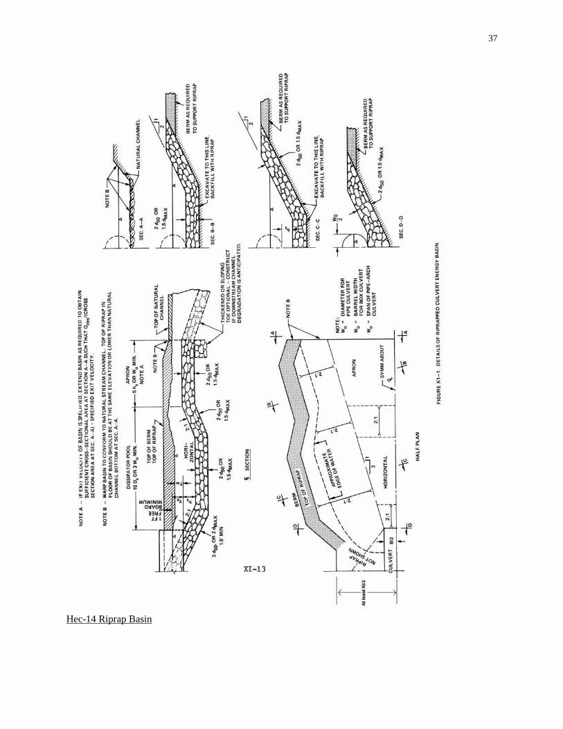
General details of the HEC-14 Riprap Basin are shown on the Hec-14 Riprap Basin Plot, shown
below. This figure is taken from the Hec-14 manual. Details on the calculation methodology are
in Appendix O: Hec-14 Riprap Basin.
To use the software you must first define the Culvert Type, Inlet and Size and the Design Q and
Tailwater Depth. With these parameters defined you then click the “Compute” button to have the
riprap basin parameters and dimensions determined and displayed.
37
Hec-14 Riprap Basin

38
The options for culvert type, inlet and size are the same as those for culvert general design.
Culvert Type, Inlet and Size
The “Culvert Type, Inlet and Size” frame is where you specify the culvert information. You
specify the culvert type using the drop-down list box to the right of “Culvert Type”.
Currently, the six types of culverts are,
RCB: Reinforced Concrete Box
RCP: Reinforced Concrete Pipe
CMP: Corrugated Metal Pipe
CPA: Concrete Pipe Arch
SPA: Steel Pipe Arch (2-2/3” by 1/2” corrugations)
SPA: Steel Pipe Arch (3” X 1” or 5” X 1” corrugations)
When you select a culvert type a default “Manning n” value is automatically displayed. You may
use the default or type in a “Manning n” value.
Culvert Inlet:
When you select a culvert type the “Inlet Type” list box is automatically filled with the inlet
types that are currently built into the software for the selected culvert type. For a selected inlet
type the default Ke value (entrance loss coefficient) is displayed. You can use the default value
or type in a “Ke” value.
Each culvert type – inlet combination has associated with it the coefficients used for inlet control
computations. These coefficients are stored internally and are not displayed on the form.
Appendix I contains a list of the inlet control coefficients.
Selecting a Size
You can specify the culvert size two ways; select a standard size or type in the dimensions.
Standard Size Selection
When you select a “Culvert Type” the available standard sizes are automatically displayed in the
drop-down list box beneath “IDOT Standard Sizes”. You can scroll the list box to select a size
and number of barrels.
Entering a Barrel Size
If you wish to enter a size click “Enter Barrel Size”, or click the option button to the left of
“Enter Barrel Size”. This will enable text boxes where you can type in the dimension(s) of the
culvert barrel and select the number of barrels.
39
Culvert Elevations and Length
You need to enter the,
Culvert Inlet Invert Elevation (elevation of the inside bottom of the culvert at the inlet).
Culvert Outlet Invert Elevation (elevation of the inside bottom of the culvert at the outlet).
Culvert Barrel Length: The length of the culvert barrel. This is the actual length of the culvert
barrel, not the horizontal distance from the inlet to the outlet.
The parameters are illustrated in the following figure:
Design Parameters
Design Q (cfs): The Q value. The discharge or flowrate through the culvert.
Tailwater Depth (ft): The tailwater depth. The depth of water at the culvert outlet, above the
outlet invert, created by down-stream conditions. Clicking “Compute TW Depth” will compute
the tailwater depth using the Design Q, the Tailwater Channel Cross-Section and the Manning
Equation (assuming uniform flow).
Results
The design parameters determined by the software are:
Minimum Width at Inlet, W(ft): This is the minimum width of the riprap basin at the inlet of
the riprap basin (the outlet of the culvert), as illustrated on the Hec-14 Riprap Basin plot, shown

40
above. This parameter is not part of Hec-14, but is recommended by the Iowa Department of
Transportation. This parameter is equal to twice the culvert(s) span.
Calculated Riprap Size, d-50 (ft): This is the minimum median size of rock to be used for the
riprap basin (Hec-14 Riprap Basin plot).
Recommended Riprap d-50: Based on the calculated riprap size, this is the recommended
riprap size if you wish to use Class E or Class B riprap. Class E is recommended if the calculated
riprap size is <= 1.2 feet, and Class B is recommended if the recommended riprap size is > 1.2
feet and <=2.0 feet. You may use the calculated riprap size for design in place of the
recommended riprap d-50.
APPROACH RIPRAP THICKNESS
The approach riprap location is the slope from the culvert outlet to the floor of the dissipator pool
(Hec-14 Riprap Basin plot). It is the location where the riprap thickness is shown as 3 d50.
Calculated Riprap Thickness (ft): This is the calculated riprap thickness to use for the
approach section. You can note on the figure that this is simply computed as 3 times the d-50.
Recommended Riprap Thickness (ft): This is the larger of the calculated riprap thickness, or 3
foot if the recommended riprap d-50 is Class E or 4.5 feet if the recommended riprap d-50 is
Class B.
BASIN/APRON RIPRAP THICKNESS
The basin/apron riprap thickness is the riprap thickness to be used for the remainder of the basin:
the dissipator pool (except for the approach) and the apron, or the locations on the Hec-14 Riprap
Basin plot where the riprap thickness is shown as 2 d50.
Calculated Riprap Thickness (ft): This is the calculated riprap thickness to use for the basin
and apron section. You can note on the figure that this is simply computed as 2 times the d-50.
Recommended Riprap Thickness (ft): This is the larger of the calculated riprap thickness, or
2.0 foot if the recommended riprap d-50 is Class E or 3.0 feet if the recommended riprap d-50 is
Class B.
Other Parameters:
The remaining parameters are listed in the table on the form. The only values discussed here are
the values relevant to the basin size. The parameters not covered here are discussed in Appendix
O: Hec-14 Riprap Basin.
Brink TW (ft): This is simply the tailwater depth: the depth above the culvert outlet invert.
hs (ft): This is an important parameter, as illustrated on the Hec-14 Riprap Basin plot above.
This is the depth of the dissipator pool below the culvert outlet invert. It is critically important

41
that the riprap basin pool bottom be placed at least this deep below the culvert outlet invert. The
design methodology is based on an estimate of scour depth, and the pool depth is based on this
scour estimate.
Basin Length (ft): This is the total length of riprap basin, from the culvert outlet to the end of
the apron. It is the sum of the dissipator pool length and the apron length.
Pool Length (ft): The length of the dissipator pool, from the culvert outlet to the start of the
apron.
Apron Length (ft): The length of the apron, from the end of the dissipator pool to the return to
natural channel conditions.
hs/d50: The Hec-14 manual states this parameter should be between 2 and 4. When you click
“Compute” the software automatically finds, if possible, a d-50 and corresponding hs such that
the ratio hs/d50 falls between 2 and 4.
TW/Yo: Ratio of tailwater depth (TW) to culvert outlet brink depth (Yo). If this ratio exceeds
0.75 the Hec-14 manual suggests that additional channel protection beyond the apron may be
needed. Please see the Hec-14 manual, chapter XI, for additional information.
Vo (ft/s): The estimated velocity at the culvert outlet.
See Appendix O: Hec-14 Riprap Basin for parameters not covered here, or for more details.

42
Appendices
Appendix A: Hydraulic Design of Highway Culverts, HDS-5
Most of the concepts, equations and coefficients used in this software for culvert hydraulic
calculations are taken from, Hydraulic Design of Highway Culverts, Hydraulic Design Series
No. 5, Report No. FHWA-IP-85-15, September 1985. This report is often referred to as HDS-5,
for Hydraulic Design Series, No. 5. The most recent version of this report is “Hydraulic Design
of Highway Culverts, Third Edition, April 2012”.
You can download a copy of the most recent report from the Internet. The download is in Adobe
Acrobat format, a PDF file. You can go directly to the pdf file for the latest version (2012) using
the URL: http://www.fhwa.dot.gov/engineering/hydraulics/pubs/12026/hif12026.pdf.
Appendix B: Copying and Pasting Values
When you right click on selected tables you either see the menu
Or
Copy
Selecting “Copy” will copy the selected items in the table to the clipboard. You can also use the
keyboard shortcut Ctrl-C to copy selected items to the clipboard. Note that values copied to the
clipboard can be pasted to other tables in the software or to other programs (such as Excel).
Paste
“Paste will paste the content in the clipboard above the currently selected top row, adding rows
as needed. Select the row you want to Paste content above before right clicking. Note that you
can use Paste to add values that have been added to the clipboard from other programs. For
example, if you copy values to the clipboard in Excel, you can then add them to the table using
Excel.

43
Insert Rows
“Insert Rows” will bring up the insert rows dialog,
Enter the Number of Rows to Insert, and that number of empty rows will be added above the
currently selected top row.
To delete rows, select the rows you wish to delete and press the “Delete” key.
Clear Values in Selected Cells
To erase the values in selected cells (without deleting the rows), select the items you wish to
erase, then right click and select “Clear Values in Selected Cells”.
Appendix C: The Iowa Runoff Chart
The following is taken from material prepared by the Iowa DOT.
In the 1950's, the Iowa State Highway Commission (now Iowa DOT} adapted Bureau of Public
Roads' Chart 1021.1, "Highway Drainage Manual", 1950. (BPR’s chart was adapted from
original work performed by W.D. Potter, "Surface Runoff from Small Agricultural Watersheds,"
Research Report No. 11-B, (Illinois) Highway Research Board, 1950.) The Iowa Runoff Chart
has been widely used by IDOT and the counties since then.
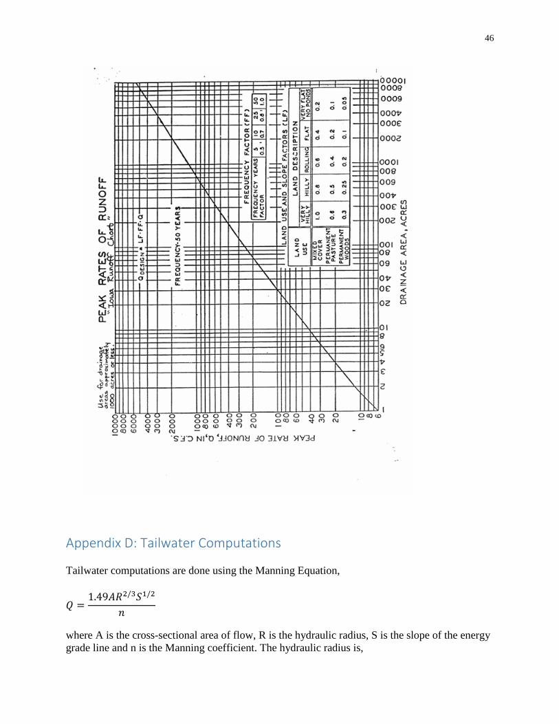
The chart is self-explanatory. However, its use does require the exercise of judgement in
selecting the land use and land slope factors. It can be used for rural watersheds draining up to
1000 acres.
The following is intended to aid that judgement:
Very Hilly Land-is best typified by the bluffs bordering the Mississippi and the Missouri
Rivers. This terrain is practically mountainous (for Iowa) in character. Small areas of very hilly
land can be found in all parts of the state. Typically, they can be found near the edge of the flood
plains of the major rivers.
44
Hilly Land-is best typified by the rolling hills of south central Iowa. Interstate 35 in Clarke and
Warren Counties traverses many hilly watersheds. Small areas of hilly land can be found in all
parts of the state.
Rolling Land-is best typified by the more gently rolling farm lands of central Iowa. Interstate 80
in Cass and Adair Counties traverses many rolling watersheds. Small areas of rolling land can be
found in all parts of the state.
Flat Land--is best typified by the farm lands of the north central part of the state. U.S. 69
traverses many flat watersheds in Hamilton and Wright Counties. Small areas of flat land can be
found in all areas of the state.
Very Flat Land-is best typified by the Missouri River flood plain. Interstate 29 is located on this
type of land for most of its length. Much of Dickinson, Emmet, Kossuth, Winnebago and Palo
Alto Counties are also in this classification. Small areas of very flat land can be found in all parts
of the state.
Use this chart only for rural watersheds and the limitations of drainage areas listed below. The
equations were developed by finding the best statistical fit to the curve on the Runoff Chart. At
the larger drainage areas (600 to 1000 acres), the equation overestimates Q taken from the Chart
by up to 7%. In most cases, however, this would not result in a larger culvert size. If the designer
questions the equation results, use the curve on the Chart. Be aware that error (overestimating or
underestimating) may also result from interpolating the Q from the curve.
English equation
For drainage areas, 2 < A < 1000 acres
Qdesign=LF x FF x Q
Where Q=8.124A0.739
Q is in ft3/s
A is in acres
Metric equation
For drainage areas, 1 < A < 400 hectares
Qdesign=LF x FF x Q
Where Q=0.446A0.740
Q is in m3/s
A is in hectares
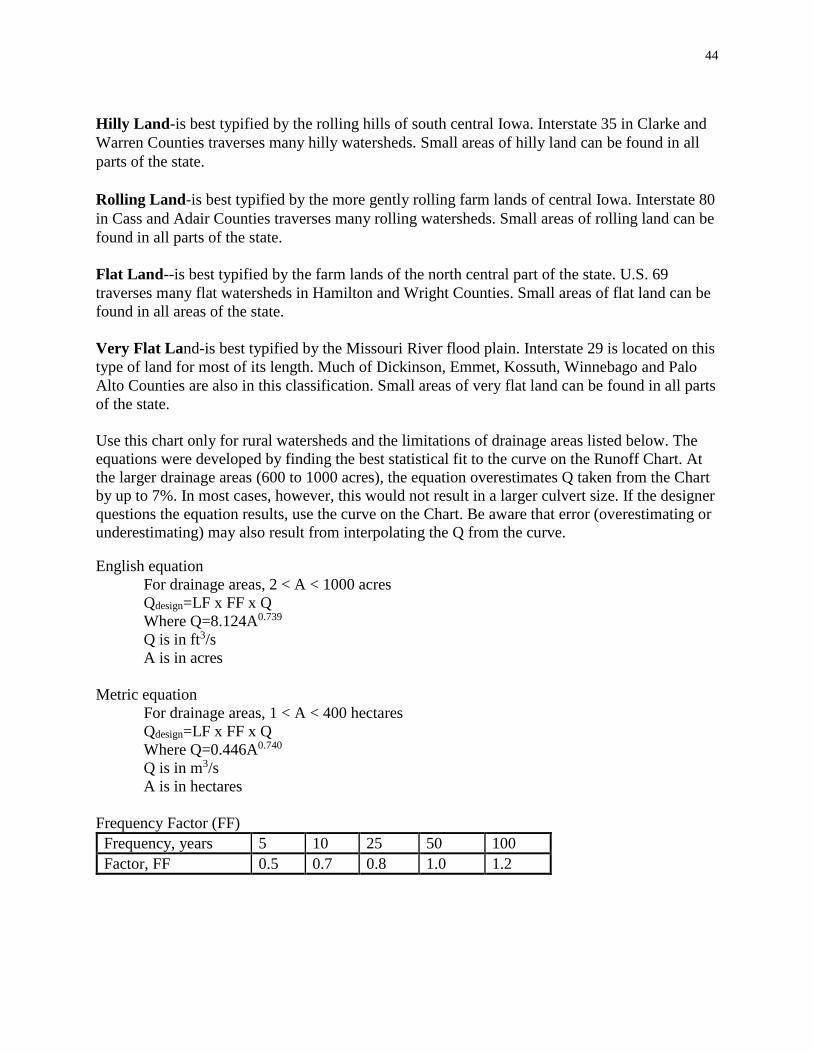
Frequency Factor (FF)
Frequency, years 5 10 25 50 100
Factor, FF 0.5 0.7 0.8 1.0 1.2
45
Land Use and Slope Description (LF) Very
Hilly
Very
Hilly/Hilly
Hilly Hilly/Rolling Rolling Rolling/Flat Flat Flat/Very
Flat
Very
Flat (no
ponds)
Mixed
Cover
1.0 0.9 0.8 0.7 0.6 0.5 0.4 0.3 0.2
Permanent
Pasture
0.6 0.55 0.5 0.45 0.4 0.3 0.2 0.15 0.1
Permanent
Woods
0.3 0.275 0.25 0.225 0.2 0.15 0.1 0.075 0.05
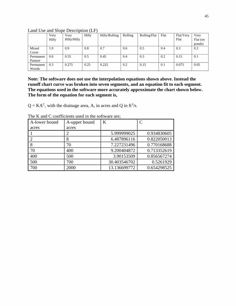
Note: The software does not use the interpolation equations shown above. Instead the
runoff chart curve was broken into seven segments, and an equation fit to each segment.
The equations used in the software more accurately approximate the chart shown below.
The form of the equation for each segment is,
Q = KAC, with the drainage area, A, in acres and Q in ft3/s.
The K and C coefficients used in the software are;
A-lower bound
acres
A-upper bound
acres
K C
1 2 5.999999025 0.934830605
2 8 6.487896116 0.822050013
8 70 7.227231496 0.770168688
70 400 9.200404872 0.713352619
400 500 3.90153509 0.856567274
500 700 30.403546702 0.5261929
700 2000 13.136699772 0.654298525
46
Appendix D: Tailwater Computations
Tailwater computations are done using the Manning Equation,
𝑄 =1.49𝐴𝑅2/3𝑆1/2
𝑛
where A is the cross-sectional area of flow, R is the hydraulic radius, S is the slope of the energy
grade line and n is the Manning coefficient. The hydraulic radius is,
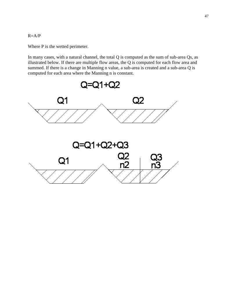
47
R=A/P
Where P is the wetted perimeter.
In many cases, with a natural channel, the total Q is computed as the sum of sub-area Qs, as
illustrated below. If there are multiple flow areas, the Q is computed for each flow area and
summed. If there is a change in Manning n value, a sub-area is created and a sub-area Q is
computed for each area where the Manning n is constant.

48
Appendix E: Tapered Inlet Design
The following information is taken from IDOT information on, Guidelines for Preliminary
Design of Bridges and Culverts. The methodology used in the software for designing tapered
inlets follows the general concepts, but the software actually computes the headloss, as discussed
in Appendix G: Tapered Inlet Calculations.
Design Guidelines for Slope Tapered Box Culverts
The purpose of slope tapered box culverts is to reduce construction costs by using a smaller
barrel but still providing acceptable hydraulic capacity and upstream headwater. These special
inlets have been used in Iowa and across the country since the 1950's or earlier. The design of
these inlets includes rigid hydraulic design and good construction practice.
The culvert site normally will meet two basic requirements to qualify for a tapered inlet. The first
is that the additional design costs are offset by the reduction in construction costs. The second is
that the site must have enough fall for the design to perform properly, typically at least six to
eight feet.
The culvert inlet is made large enough to keep the depth of water at the entrance within
allowable limits. The slope taper section funnels the water down a steep slope as the culvert
width decreases. The barrel section is designed to flow nearly full when carrying the design
discharge. Generally the outlet has a flume and basin for energy dissipation.
Design Steps
There are five basic steps for the hydraulic design of a box culvert with a slope tapered inlet.
1. Determine the design discharge. The Iowa Runoff Chart shall be used for rural watersheds
draining 1000 acres (400 hectares) or less.
2. Determine the allowable depth of water at the inlet. Typically, the Iowa DOT allows one
foot (0.3 m) of water above the top of the inlet.
3. Select an inlet size that results in a flow depth less than or equal to the allowable. Inlet
control nomographs from FHWA’s Hydraulic Design of Highway Culverts, HDS No. 5, can
be used for this.
4. Select a barrel size and slope that results in the barrel flowing less than full. The barrel
height should be the same as the inlet, while the barrel width should generally be no less than
50 to 60% of the inlet width. Select a slope steep enough to maintain supercritical
flow. Charts in FHWA’s Design Charts for Open-Channel Flow, HDS No. 3, have been
developed from Manning=s equation and can be used to select the appropriate slope.
5. Determine the drop and length of the slope tapered section. The minimum drop needed is the
specific energy at the inlet (H1) minus the specific energy at the barrel (H2) plus energy
losses (HL). Specific energy is the depth plus velocity head at a given location.
The following guidelines, charts and worksheets (English and metric units) are provided to assist
in the hydraulic design.

49
When the inlet will be raised significantly to create a pond, geotechnical concerns must be
considered to ensure that seepage through the embankment is not excessive.
General Guidelines 1. HW from inlet control charts for proposed inlet size, no greater than D + 2 ft. (D + 0.6 m.)
2. The height (D) of the structure does not change.
3. Calculated Z may be rounded to the next higher increment as described below.
Minimum Z = 3 ft. (0.9 m.)
4. Taper can be designed by using the RCB standard reinforced steel pattern of inlet size for the
entire length of the taper and varying the length of the transverse steel.
5. The barrel outlet flowline is usually set at least ½ (D) above streambed. This prevents the
barrel from “drowning out”.
6. The outlet usually has a flume with a basin that is buried 4 ft. to 6 ft. (1.2 m. to 1.8 m.) below
streambed, to help dissipate energy.
7. The barrel slope (So) should generally be 1.5% or steeper in order to maintain supercritical
flow and the maximum flow depth of 0.9D in the barrel. (See “Design Charts for Open
Channel flow”, HDS No. 3, FHWA, to determine specific flow depths for various slopes.)
8. An attempt should be made to design barrel sizes to conform with standard RCB sizes. This
may mean starting with a “wide” non-standard inlet.
9. Assume energy loss, HL = 0.2 ft. (0.1 m.) for all cases.
Guidelines for single RCBs
1. Use drop rate (L/Z) of approximately 3:1.
2. Ratio of barrel width to inlet width (B2/B1) should be 50% or greater.
3. For Z=3 ft., use L=10 ft. For Z=4 ft., use L=12 ft. For Z=5 ft., use L=15 ft.
(For Z=0.9 m., use L=3.0 m. For Z=1.2 m., use L=3.6 m. For Z=1.5 m., use L=4.5 m.)
Guidelines for Twin RCBs
1. Use drop rate (L/Z) of 5:1 (min.)
2. Ratio of barrel width to inlet width (B2/B1) should be 60% or greater.
3. L is determined either by (B1 - B2) x 4 or Z x 5, whichever is greater. This insures a
minimum side taper of 4:1. L should generally be in 5 ft. (1.5 m.) increments.
Definitions
HW -- Headwater from inlet control charts
H1 -- Specific energy head at inlet
H2 -- Specific energy head at barrel
B1 -- Width of inlet opening
B2 -- Width of barrel opening
D -- Height of opening
HL -- Energy loss
dc -- Critical depth
Z -- Drop in flowline required
L -- Length of taper section
So -- Slope of barrel
V2/2g -- Velocity head
N = L/Z = Slope of taper section
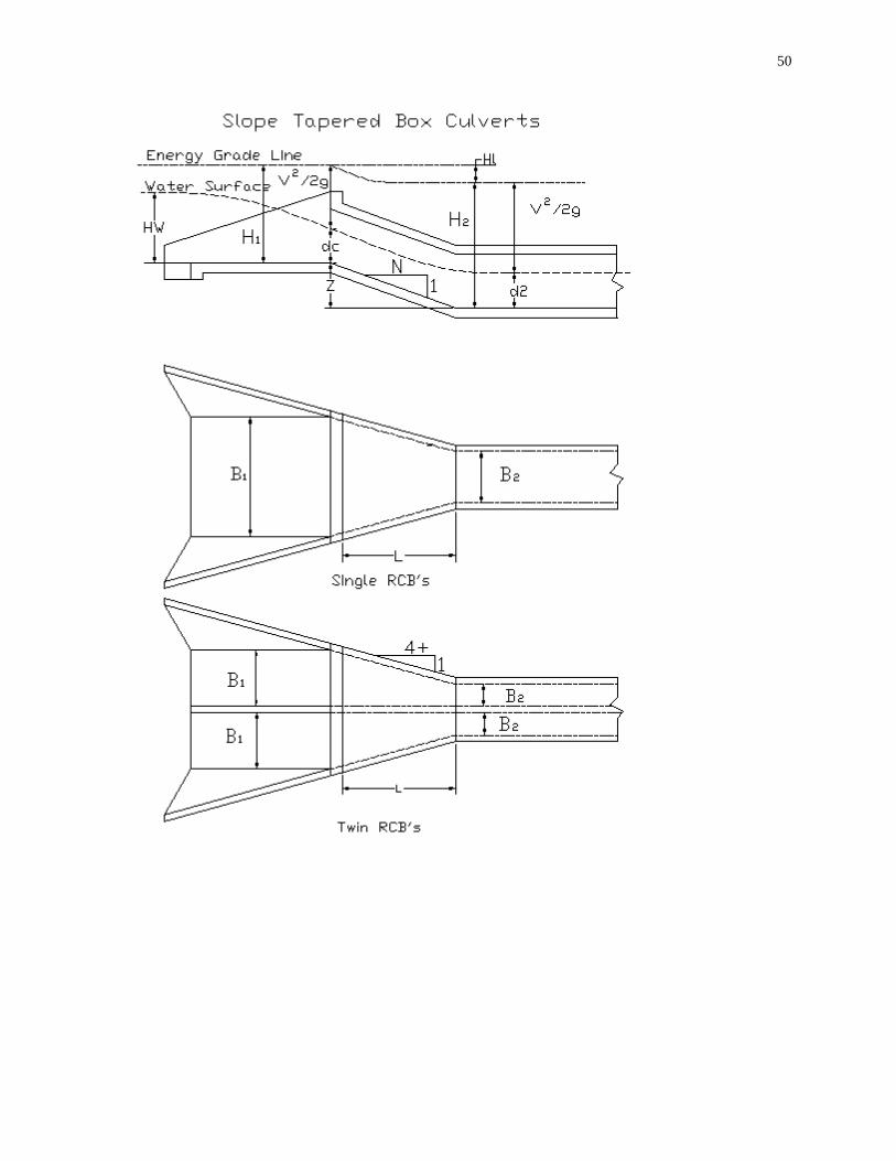
50
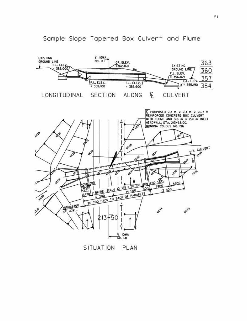
51
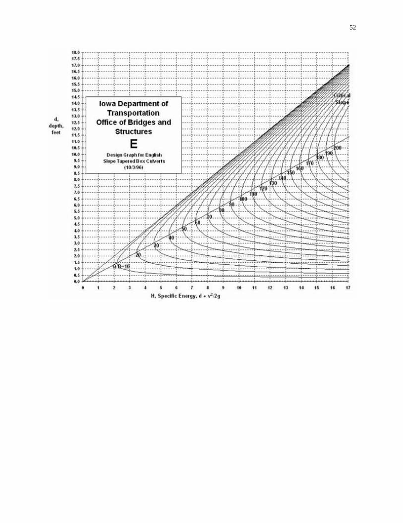
52
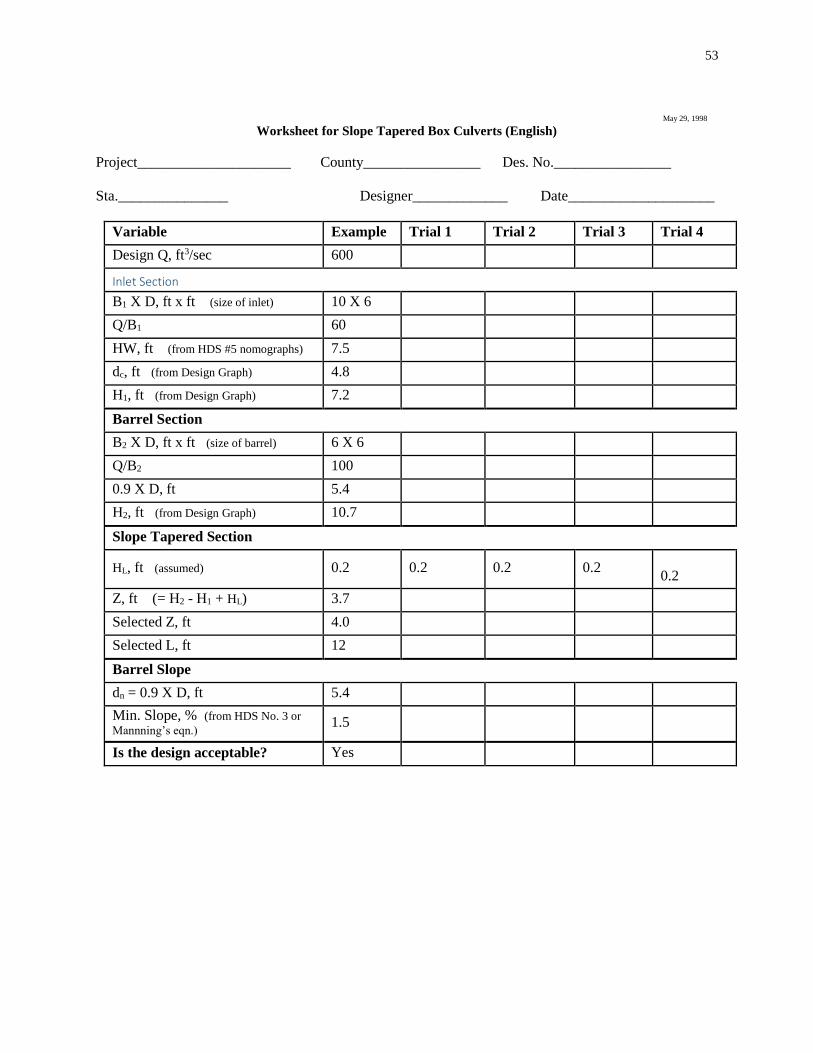
53
May 29, 1998
Worksheet for Slope Tapered Box Culverts (English)
Project_____________________ County________________ Des. No.________________
Sta._______________ Designer_____________ Date____________________
Variable Example Trial 1 Trial 2 Trial 3 Trial 4
Design Q, ft3/sec 600
Inlet Section
B1 X D, ft x ft (size of inlet) 10 X 6
Q/B1 60
HW, ft (from HDS #5 nomographs) 7.5
dc, ft (from Design Graph) 4.8
H1, ft (from Design Graph) 7.2
Barrel Section
B2 X D, ft x ft (size of barrel) 6 X 6
Q/B2 100
0.9 X D, ft 5.4
H2, ft (from Design Graph) 10.7
Slope Tapered Section
HL, ft (assumed) 0.2 0.2 0.2 0.2
0.2
Z, ft (= H2 - H1 + HL) 3.7
Selected Z, ft 4.0
Selected L, ft 12
Barrel Slope
dn = 0.9 X D, ft 5.4
Min. Slope, % (from HDS No. 3 or
Mannning’s eqn.) 1.5
Is the design acceptable? Yes
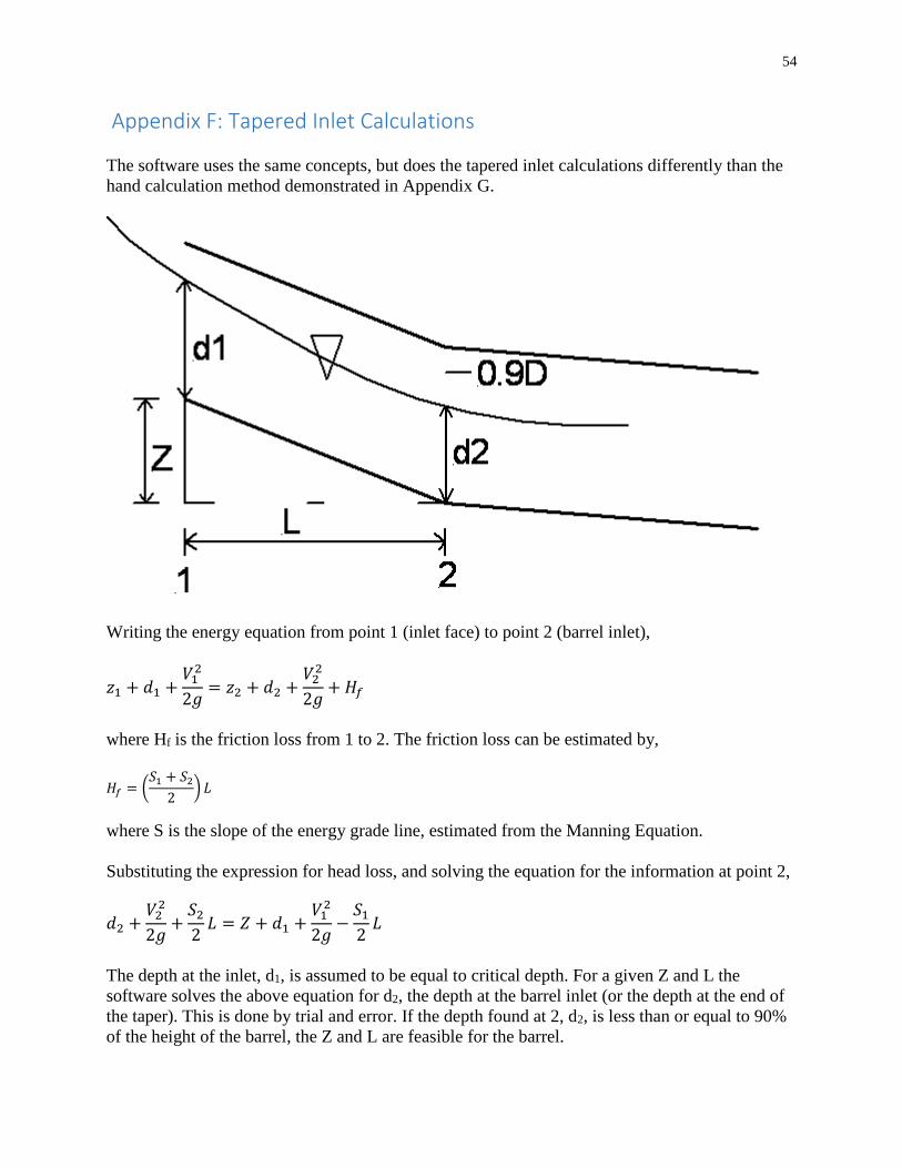
54
Appendix F: Tapered Inlet Calculations
The software uses the same concepts, but does the tapered inlet calculations differently than the
hand calculation method demonstrated in Appendix G.
Writing the energy equation from point 1 (inlet face) to point 2 (barrel inlet),
𝑧1 + 𝑑1 +𝑉12
2𝑔= 𝑧2 + 𝑑2 +
𝑉22
2𝑔+ 𝐻𝑓
where Hf is the friction loss from 1 to 2. The friction loss can be estimated by,
𝐻𝑓 = (𝑆1 + 𝑆2
2) 𝐿
where S is the slope of the energy grade line, estimated from the Manning Equation.
Substituting the expression for head loss, and solving the equation for the information at point 2,
𝑑2 +𝑉22
2𝑔+𝑆22𝐿 = 𝑍 + 𝑑1 +
𝑉12
2𝑔−𝑆12𝐿
The depth at the inlet, d1, is assumed to be equal to critical depth. For a given Z and L the
software solves the above equation for d2, the depth at the barrel inlet (or the depth at the end of
the taper). This is done by trial and error. If the depth found at 2, d2, is less than or equal to 90%
of the height of the barrel, the Z and L are feasible for the barrel.

55

56
Appendix G: Drop Inlet Design
The following information is taken from IDOT information on Guidelines for Preliminary
Design of Bridges and Culverts. The software uses the following equations and concepts, but
also does inlet control headwater computations and uses the larger of inlet control and outlet
control headwater to estimate the barrel headwater at the inlet.
Design Guidelines for Drop Inlet Culverts January 11, 1999
Drop inlets for pipe and box culverts can be beneficial solutions to some drainage and erosion
problems. Hydraulically, they are useful when a culvert has limited available head
upstream. Also, they can be used to raise the flowline to create a pond or stop channel erosion
upstream.
When evaluating the hydraulics of drop inlet culverts, two controls must be checked to determine
the design high water of the culvert. The first is barrel control using the orifice equation, also
known as the full-flow equation, taken from a U.S. Soil Conservation Service technical
memorandum for drop inlets. The equation is similar to the outlet control equation in FHWA’s
Hydraulic Design of Highway Culverts, HDS No. 5. The second is weir control, using the broad-
crested weir equation. The equation giving the highest water elevation is considered the
controlling headwater.
A trial and error solution is needed to determine what size of barrel and weir are needed. Start by
sizing the barrel and analyzing the hydraulics. When an acceptable size and headwater are
obtained, assume a drop inlet opening of 1.5 to 2.0 times the barrel opening. Then calculate the
head created by the weir and determine if a different size inlet is needed.
Worksheets (English and metric units) are attached to aid in the calculations.
Barrel (Full Flow) Equation
𝑄 = 𝐴 [2𝑔𝐻
1 + 𝐾𝑒 + 𝐾𝑏 + 𝐾𝑓𝐿𝑏]
0.5
where Q = discharge, ft3/sec (m3/sec)
A = area of culvert barrel, ft2 (m2)
g = acceleration due to gravity = 32.2 ft/sec2 (9.81 m/sec2)
H = head (energy) needed to pass the flow through the barrel, feet (m)
Ke = entrance loss coefficient
Kb = bend loss coefficient
Lb = length of barrel, ft
Kf = friction loss coefficient
= 29.16 n2 / R1.33 (English), or = 19.63n2 / R1.33 (metric)
n = roughness coefficient

57
R = hydraulic radius of barrel = area / wetted perimeter, ft (m)
Assume Ke + Kb = 1.0 for typical Iowa DOT drop inlet
n = 0.012 for smooth pipe, or 0.024 for corrugated metal
R = A/(2(W + H)) for RCBs or D/4 for round pipe barrels
ho = height of hydraulic grade line at outlet = TW or (dc + D)/2, whichever is greater, ft
(m)
(TW can be determined from the Manning’s equation using a downstream valley
section. dc can be found in Chart 4 or 14 in FHWA’s HDS No. 5. D is the height of the
barrel.)
This results in the following full flow equation, assuming English units and a smooth (e.g.,
concrete) barrel:
𝑄 = 𝐴 [64.4𝐻
2 + 0.0042 (𝐿𝑏𝑅1.33
)]
0.5
Or solving for H,
(Equation 1 – English)
𝐻 = [0.1246𝑄
𝐴]2
[2 +0.0042𝐿𝑏𝑅1.33
]
Equation 1 in metric units converts to the following:
(Equation 2 – Metric)
𝐻 = [0.226𝑄
𝐴]2
[2 +0.0028𝐿𝑏𝑅1.33
]
H is the head (energy loss) required to pass the flow through the barrel. To determine the
headwater (HW) elevation at the inlet, add H and ho to the outlet flowline elevation, where ho is
either tailwater (TW) depth or (dc + D)/2, whichever is greater. (See Chapter III of FHWA’s
“Hydraulic Design of Highway Culverts”, HDS No. 5, for a more detailed discussion of barrel
[outlet] control.)
Then compare the HW elevation to allowable head water (AHW) elevation. If HW > AHW, a
larger barrel is needed. If HW < AHW, either try a smaller barrel size or proceed with the weir
control calculations as described below.
Weir Equation
𝑄 = 𝐶𝐿𝑤𝐻1.5
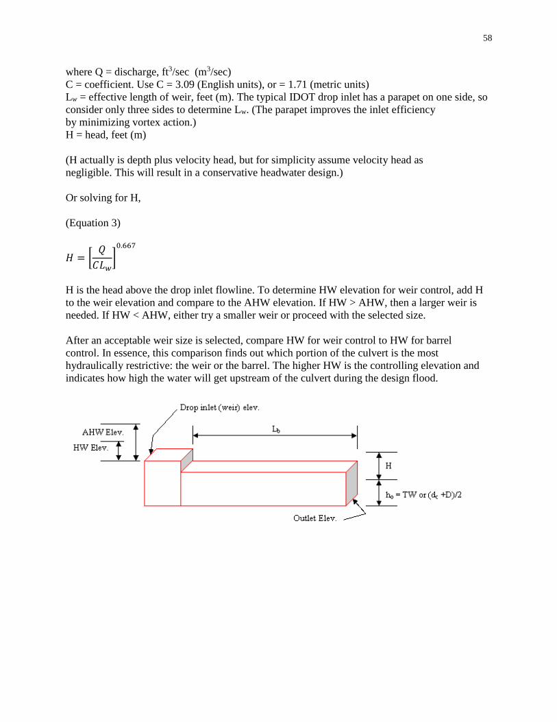
58
where Q = discharge, ft3/sec (m3/sec)
C = coefficient. Use C = 3.09 (English units), or = 1.71 (metric units)
Lw = effective length of weir, feet (m). The typical IDOT drop inlet has a parapet on one side, so
consider only three sides to determine Lw. (The parapet improves the inlet efficiency
by minimizing vortex action.)
H = head, feet (m)
(H actually is depth plus velocity head, but for simplicity assume velocity head as
negligible. This will result in a conservative headwater design.)
Or solving for H,
(Equation 3)
𝐻 = [𝑄
𝐶𝐿𝑤]0.667
H is the head above the drop inlet flowline. To determine HW elevation for weir control, add H
to the weir elevation and compare to the AHW elevation. If HW > AHW, then a larger weir is
needed. If HW < AHW, either try a smaller weir or proceed with the selected size.
After an acceptable weir size is selected, compare HW for weir control to HW for barrel
control. In essence, this comparison finds out which portion of the culvert is the most
hydraulically restrictive: the weir or the barrel. The higher HW is the controlling elevation and
indicates how high the water will get upstream of the culvert during the design flood.
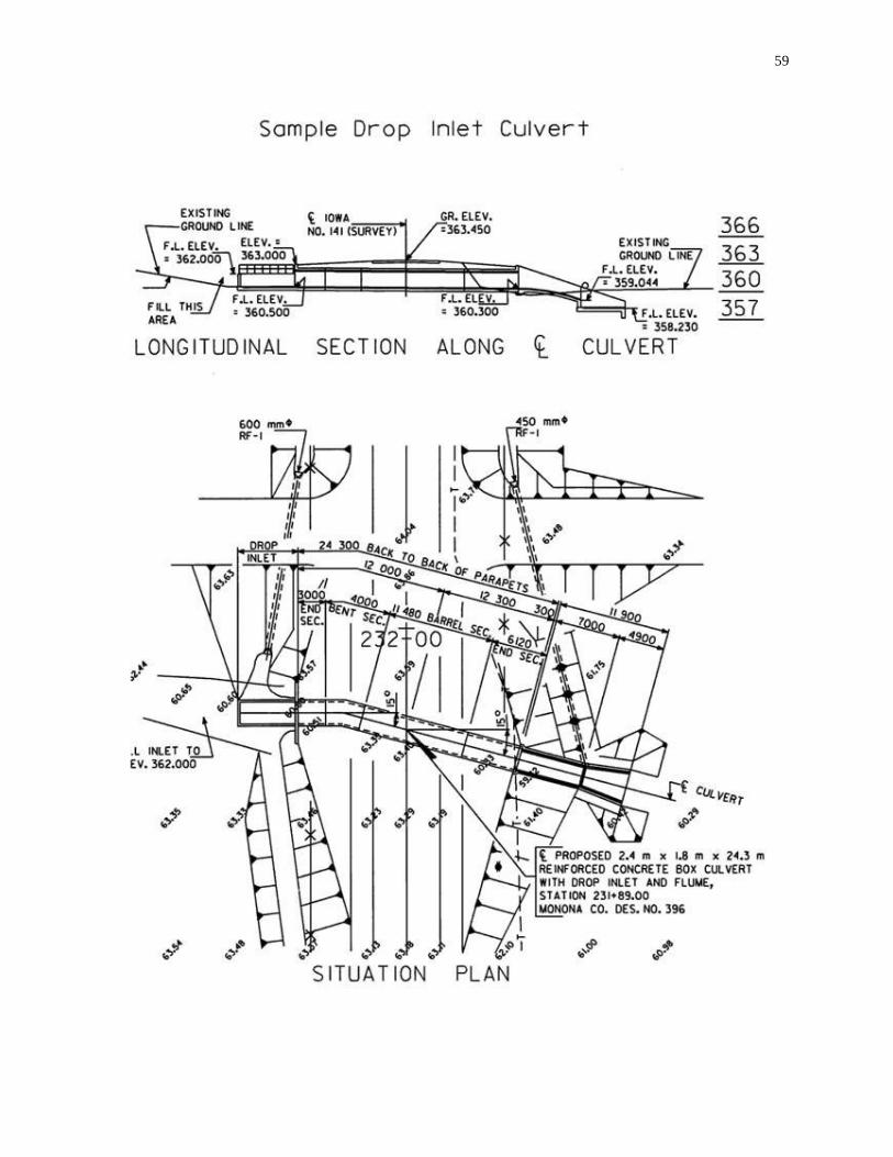
59
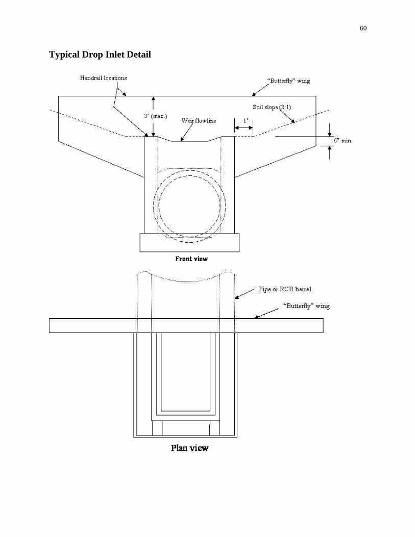
60
Typical Drop Inlet Detail
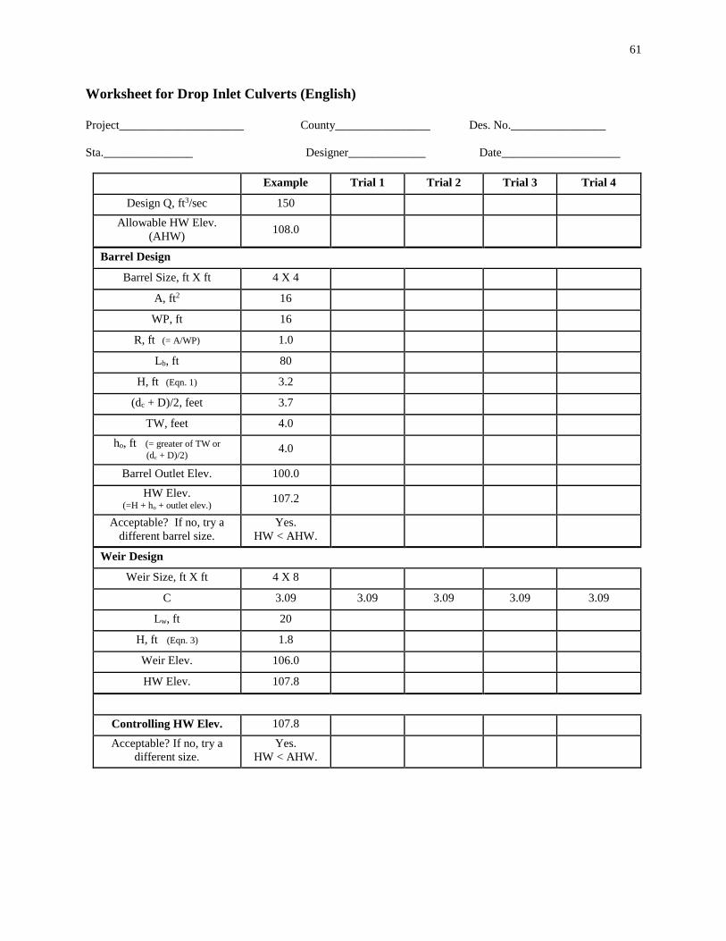
61
Worksheet for Drop Inlet Culverts (English)
Project_____________________ County________________ Des. No.________________
Sta._______________ Designer_____________ Date____________________
Example Trial 1 Trial 2 Trial 3 Trial 4
Design Q, ft3/sec 150
Allowable HW Elev.
(AHW) 108.0
Barrel Design
Barrel Size, ft X ft 4 X 4
A, ft2 16
WP, ft 16
R, ft (= A/WP) 1.0
Lb, ft 80
H, ft (Eqn. 1) 3.2
(dc + D)/2, feet 3.7
TW, feet 4.0
ho, ft (= greater of TW or (dc + D)/2)
4.0
Barrel Outlet Elev. 100.0
HW Elev. (=H + ho + outlet elev.)
107.2
Acceptable? If no, try a
different barrel size.
Yes.
HW < AHW.
Weir Design
Weir Size, ft X ft 4 X 8
C 3.09 3.09 3.09 3.09 3.09
Lw, ft 20
H, ft (Eqn. 3) 1.8
Weir Elev. 106.0
HW Elev. 107.8
Controlling HW Elev. 107.8
Acceptable? If no, try a
different size.
Yes.
HW < AHW.

62
Appendix H: General Design Inlets Nomenclature
The nomenclature used to describe the same inlet type varies between HY8 (the FHWA culvert
software program) and HDS-5. The following table lists the inlet types included in version 3.0 of
the software, for Design: General. This software follows the HDS-5 Description. * is used to
indicate degrees.
Culvert Type Software (HDS-5) Inlet
Description
HY-8 Inlet
Description
HDS-5
Chart-
Nomograph
Concrete Pipe Square edge with headwall Square edge with headwall 1-1
Concrete Pipe Groove end with headwall Grooved end in headwall 1-2
Concrete Pipe Groove end projecting Grooved end projection 1-3
Concrete Pipe Beveled ring, 45* Beveled Edge (1:1) 3-A
Concrete Pipe Beveled ring, 33.7* Beveled Edge (1.5:1) 3-B
Concrete Box 90* headwall, 3/4” chamfers Headwall, Square edge (90-45
DEG.)
10-1
Concrete Box 90* headwall, 33.7* bevels Headwall, 1.5:1 Bevel (90
DEG.)
10-3
Concrete Box 90* headwall, 45* bevels Headwall, 1:1 Bevel 10-2
Concrete Box 30* to 75* wingwall flares Wingwall, Square Edge (30-75
DEG. FLARE)
8-1
Concrete Box 90* and 15* wingwall flares Wingwall, Square Edge (90&15
DEG. FLARE
8-2
Concrete Box 0* wingwall flares Wingwall, Square Edge (DEG.
FLARE)
8-3
Concrete Box 18* to 33.7* wingwall flares,
d=.083D
Wingwall, 1.5:1 BEVEL (18-34
DEG. FLARE)
9-2
Concrete Box 45* wingwall flare, d=.043D Wingwall, 1:1 BEVEL (45
DEG. FLARE)
9-1
Metal Pipe Headwall Square edge with Headwall 2-1
Metal Pipe Mitered to slope Mitered to Conform to Slope 2-2
Metal Pipe Projecting Thin edge projecting 2-3
Concrete Pipe Arch Square edge with headwall Square edge with headwall 1-1
Concrete Pipe Arch Groove end with headwall Grooved end in headwall 1-2
Concrete Pipe Arch Groove end projecting Grooved end projection 1-3
Steel Pipe Arch 90* headwall Headwall 34-1
Steel Pipe Arch Mitered to slope Mitered 34-2
Steel Pipe Arch Projecting Projecting 34-3

63
Appendix I: Inlet Control
The equations and coefficients used for inlet control are taken from HDS-5 (Appendix A). The
following lists the inlet control equations and coefficients (HDS-5, Table 8 and Table 9, pages
146-148).
Unsubmerged Equations
Form (1)
𝐻𝑊𝑖
𝐷=𝐻𝑐
𝐷+ 𝐾 [
𝑄
𝐴𝐷0.5]𝑀
− 0.5𝑆
Form (2)
𝐻𝑊𝑖
𝐷= 𝐾 [
𝑄
𝐴𝐷0.5]𝑀
Submerged Equation
𝐻𝑊𝑖
𝐷= 𝑐 [
𝑄
𝐴𝐷0.5]2
+ 𝑌 − 0.5𝑆
Notes:
The unsubmerged equations apply up to about 𝑄
𝐴𝐷0.5 = 3.5 . The submerged equation applies
above about 𝑄
𝐴𝐷0.5 = 4.0.
For mitered inlets use +0.7S in place of –0.5S as the slope correction.
Definitions
HWi Headwater depth above inlet control section invert
D Interior height of the culvert barrel
Hc Specific head at critical depth (dc +Vc2/2g)
Q Discharge
A Full cross sectional area of culvert barrel
S Culvert barrel slope
K,M,c,Y Constants from table 9
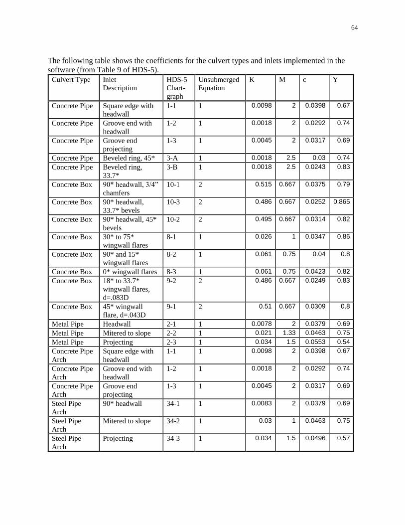
64
The following table shows the coefficients for the culvert types and inlets implemented in the
software (from Table 9 of HDS-5).
Culvert Type Inlet
Description
HDS-5
Chart-
graph
Unsubmerged
Equation
K M c Y
Concrete Pipe Square edge with
headwall
1-1 1 0.0098 2 0.0398 0.67
Concrete Pipe Groove end with
headwall
1-2 1 0.0018 2 0.0292 0.74
Concrete Pipe Groove end
projecting
1-3 1 0.0045 2 0.0317 0.69
Concrete Pipe Beveled ring, 45* 3-A 1 0.0018 2.5 0.03 0.74
Concrete Pipe Beveled ring,
33.7*
3-B 1 0.0018 2.5 0.0243 0.83
Concrete Box 90* headwall, 3/4”
chamfers
10-1 2 0.515 0.667 0.0375 0.79
Concrete Box 90* headwall,
33.7* bevels
10-3 2 0.486 0.667 0.0252 0.865
Concrete Box 90* headwall, 45*
bevels
10-2 2 0.495 0.667 0.0314 0.82
Concrete Box 30* to 75*
wingwall flares
8-1 1 0.026 1 0.0347 0.86
Concrete Box 90* and 15*
wingwall flares
8-2 1 0.061 0.75 0.04 0.8
Concrete Box 0* wingwall flares 8-3 1 0.061 0.75 0.0423 0.82
Concrete Box 18* to 33.7*
wingwall flares,
d=.083D
9-2 2 0.486 0.667 0.0249 0.83
Concrete Box 45* wingwall
flare, d=.043D
9-1 2 0.51 0.667 0.0309 0.8
Metal Pipe Headwall 2-1 1 0.0078 2 0.0379 0.69
Metal Pipe Mitered to slope 2-2 1 0.021 1.33 0.0463 0.75
Metal Pipe Projecting 2-3 1 0.034 1.5 0.0553 0.54
Concrete Pipe
Arch
Square edge with
headwall
1-1 1 0.0098 2 0.0398 0.67
Concrete Pipe
Arch
Groove end with
headwall
1-2 1 0.0018 2 0.0292 0.74
Concrete Pipe
Arch
Groove end
projecting
1-3 1 0.0045 2 0.0317 0.69
Steel Pipe
Arch
90* headwall 34-1 1 0.0083 2 0.0379 0.69
Steel Pipe
Arch
Mitered to slope 34-2 1 0.03 1 0.0463 0.75
Steel Pipe
Arch
Projecting 34-3 1 0.034 1.5 0.0496 0.57
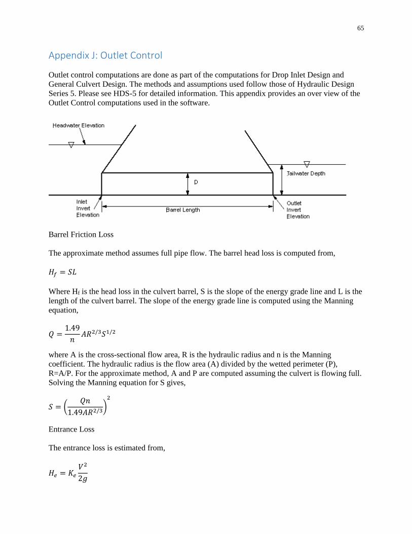
65
Appendix J: Outlet Control
Outlet control computations are done as part of the computations for Drop Inlet Design and
General Culvert Design. The methods and assumptions used follow those of Hydraulic Design
Series 5. Please see HDS-5 for detailed information. This appendix provides an over view of the
Outlet Control computations used in the software.
Barrel Friction Loss
The approximate method assumes full pipe flow. The barrel head loss is computed from,
𝐻𝑓 = 𝑆𝐿
Where Hf is the head loss in the culvert barrel, S is the slope of the energy grade line and L is the
length of the culvert barrel. The slope of the energy grade line is computed using the Manning
equation,
𝑄 =1.49
𝑛𝐴𝑅2/3𝑆1/2
where A is the cross-sectional flow area, R is the hydraulic radius and n is the Manning
coefficient. The hydraulic radius is the flow area (A) divided by the wetted perimeter (P),
R=A/P. For the approximate method, A and P are computed assuming the culvert is flowing full.
Solving the Manning equation for S gives,
𝑆 = (𝑄𝑛
1.49𝐴𝑅2/3)2
Entrance Loss
The entrance loss is estimated from,
𝐻𝑒 = 𝐾𝑒𝑉2
2𝑔

66
where Ke is the entrance loss coefficient, and V is the barrel velocity, assuming full culvert flow.
Exit Loss
The exit loss is estimated from,
𝐻𝑜 = 1.0 (𝑉2
2𝑔−𝑉𝑑2
2𝑔)
where Vd is the channel velocity downstream of the culvert. The downstream velocity is usually
neglected, so the exit loss is usually computed as,
𝐻𝑜 =𝑉2
2𝑔
Writing the energy equation from the inlet to the outlet,
𝐻𝑊 −𝐻𝑒 − 𝐻𝑓 − 𝐻𝑜 = 𝑇𝑊 + 𝑂𝑒
Where Oe is the outlet invert elevation, TW is the tailwater depth above the outlet invert, and
HW is the headwater elevation at the inlet.
In the approximate HDS-5 method, the elevation where the total head line crosses the outlet is
adjusted to account for partly full flow. The headwater elevation, under outlet control, is
computed from,
𝐻𝑊 = 𝑂𝑒 + ℎ𝑜 + 𝐻𝑒 + 𝐻𝑓 + 𝐻𝑜
where,
ℎ𝑜 =(𝑑𝑐+𝐷)
2 or TW (whichever is larger)
where dc is critical depth in the barrel and D is the inside height of the culvert barrel.
HDS-5 notes that the approximate method gives satisfactory results down to a headwater depth
of about 0.75D. For accurate results when the headwater depth at the inlet is less than 0.75D
water surface profile computations are required.
This software does not compute water surface profiles, but uses the HDS-5 approximate method
for computing the headwater elevation under outlet control.
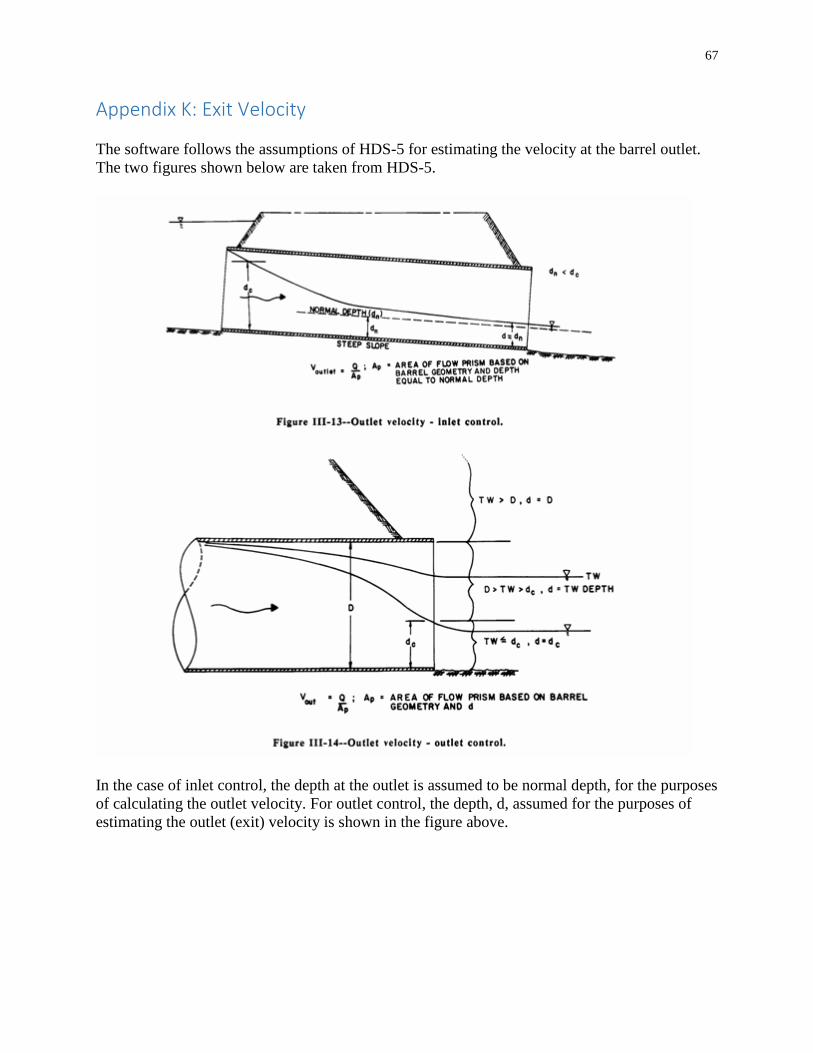
67
Appendix K: Exit Velocity
The software follows the assumptions of HDS-5 for estimating the velocity at the barrel outlet.
The two figures shown below are taken from HDS-5.
In the case of inlet control, the depth at the outlet is assumed to be normal depth, for the purposes
of calculating the outlet velocity. For outlet control, the depth, d, assumed for the purposes of
estimating the outlet (exit) velocity is shown in the figure above.

68
Appendix L: IDOT Standard Sizes
The following tables show the Iowa DOT standard sizes for selected culvert types, along with
some non-standard combinations (mainly for multiple barrels). All the sizes shown are evaluated
when the software determines acceptable culverts under “Culvert”, “IDOT Standard Design”.
The sizes shown are also displayed as “IDOT Standard Sizes” under “Culvert”, “General
Design”.
IA DOT Standard Sizes: Concrete Box
Standard Barrels Width (ft) Height (ft)
Yes Single 3 3
Yes Single 4 4 Yes Single 5 3
Yes Single 5 4
Yes Single 5 5 Yes Single 5 6
Yes Single 6 3 Yes Single 6 4
Yes Single 6 5
Yes Single 6 6 Yes Single 6 8
Yes Single 8 4 Yes Single 8 5
Yes Single 8 6 Yes Single 8 7
Yes Single 8 8
Yes Single 8 9
Yes Single 8 10
Yes Single 10 4 Yes Single 10 5
Yes Single 10 6 Yes Single 10 7
Yes Single 10 8
Yes Single 10 9
Yes Single 10 10
Yes Single 10 11
Yes Single 10 12
Yes Single 12 4
Yes Single 12 5
Yes Single 12 6
Yes Single 12 7
Yes Single 12 8
Yes Single 12 9
Yes Single 12 10
Yes Single 12 11
Yes Single 12 12 Yes Twin 8 4
Yes Twin 8 5
Yes Twin 8 6
Yes Twin 8 7
Yes Twin 8 8
Yes Twin 8 9
Yes Twin 8 10 Yes Twin 10 4
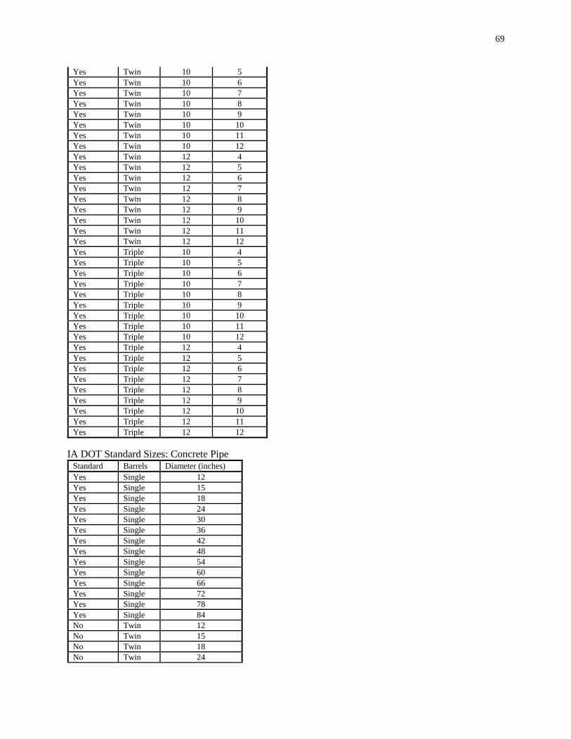
69
Yes Twin 10 5
Yes Twin 10 6 Yes Twin 10 7
Yes Twin 10 8 Yes Twin 10 9
Yes Twin 10 10 Yes Twin 10 11
Yes Twin 10 12
Yes Twin 12 4
Yes Twin 12 5
Yes Twin 12 6 Yes Twin 12 7
Yes Twin 12 8 Yes Twin 12 9
Yes Twin 12 10
Yes Twin 12 11
Yes Twin 12 12
Yes Triple 10 4
Yes Triple 10 5
Yes Triple 10 6
Yes Triple 10 7
Yes Triple 10 8
Yes Triple 10 9
Yes Triple 10 10
Yes Triple 10 11
Yes Triple 10 12
Yes Triple 12 4
Yes Triple 12 5
Yes Triple 12 6
Yes Triple 12 7
Yes Triple 12 8
Yes Triple 12 9
Yes Triple 12 10
Yes Triple 12 11
Yes Triple 12 12
IA DOT Standard Sizes: Concrete Pipe
Standard Barrels Diameter (inches)
Yes Single 12
Yes Single 15 Yes Single 18
Yes Single 24
Yes Single 30 Yes Single 36
Yes Single 42 Yes Single 48
Yes Single 54 Yes Single 60
Yes Single 66
Yes Single 72 Yes Single 78
Yes Single 84 No Twin 12
No Twin 15 No Twin 18
No Twin 24

70
No Twin 30
No Twin 36 No Twin 42
No Twin 48 No Twin 54
No Twin 60 No Twin 66
No Twin 72
No Twin 78 No Twin 84
No Triple 12 No Triple 15
No Triple 18 No Triple 24
No Triple 30
No Triple 36 No Triple 42
No Triple 48 No Triple 54
No Triple 60
No Triple 66 No Triple 72
No Triple 78 No Triple 84

71
IA DOT Standard Sizes: Corrugated Metal Pipe
Standard Barrels Diameter (inches)
Yes Single 12
Yes Single 15
Yes Single 18
Yes Single 24
Yes Single 30
Yes Single 36
Yes Single 42
Yes Single 48
Yes Single 54
Yes Single 60
Yes Single 66
Yes Single 72
Yes Single 78
Yes Single 84
No Twin 12
No Twin 15
No Twin 18
No Twin 24
No Twin 30
No Twin 36
No Twin 42
No Twin 48
No Twin 54
No Twin 60
No Twin 66
No Twin 72
No Twin 78
No Twin 84
No Triple 12
No Triple 15
No Triple 18
No Triple 24
No Triple 30
No Triple 36
No Triple 42
No Triple 48
No Triple 54
No Triple 60
No Triple 66
No Triple 72
No Triple 78
No Triple 84
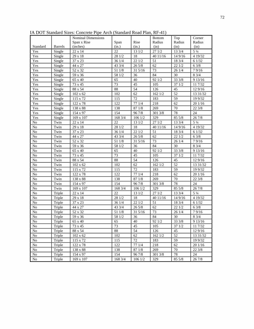
72
IA DOT Standard Sizes: Concrete Pipe Arch (Standard Road Plan, RF-41) Standard
Barrels
Nominal Dimensions Span x Rise (inches)
Span (in.)
Rise (in.)
Bottom Radius (in)
Top Radius (in)
Corner Radius (in)
Yes Single 22 x 14 22 13 1/2 27 1/2 13 3/4 5 ¼
Yes Single 29 x 18 28 1/2 18 40 11/16 14 9/16 4 19/32 Yes Single 37 x 23 36 1/4 22 1/2 51 18 3/4 6 1/32
Yes Single 44 x 27 43 3/4 26 5/8 62 22 1/2 6 3/8 Yes Single 52 x 32 51 1/8 31 5/16 73 26 1/4 7 9/16
Yes Single 59 x 36 58 1/2 36 84 30 8 3/4
Yes Single 65 x 40 65 40 92 1/2 33 3/8 9 13/16 Yes Single 73 x 45 73 45 105 37 1/2 11 7/32
Yes Single 88 x 54 88 54 126 45 12 9/16 Yes Single 102 x 62 102 62 162 1/2 52 13 31/32
Yes Single 115 x 72 115 72 183 59 19 9/32
Yes Single 122 x 78 122 77 1/4 218 62 20 1/16 Yes Single 138 x 88 138 87 1/8 269 70 22 3/8
Yes Single 154 x 97 154 96 7/8 301 3/8 78 24
Yes Single 169 x 107 168 3/4 106 1/2 329 85 5/8 26 7/8 No Twin 22 x 14 22 13 1/2 27 1/2 13 3/4 5 ¼
No Twin 29 x 18 28 1/2 18 40 11/16 14 9/16 4 19/32 No Twin 37 x 23 36 1/4 22 1/2 51 18 3/4 6 1/32
No Twin 44 x 27 43 3/4 26 5/8 62 22 1/2 6 3/8 No Twin 52 x 32 51 1/8 31 5/16 73 26 1/4 7 9/16
No Twin 59 x 36 58 1/2 36 84 30 8 3/4
No Twin 65 x 40 65 40 92 1/2 33 3/8 9 13/16 No Twin 73 x 45 73 45 105 37 1/2 11 7/32
No Twin 88 x 54 88 54 126 45 12 9/16 No Twin 102 x 62 102 62 162 1/2 52 13 31/32
No Twin 115 x 72 115 72 183 59 19 9/32 No Twin 122 x 78 122 77 1/4 218 62 20 1/16
No Twin 138 x 88 138 87 1/8 269 70 22 3/8
No Twin 154 x 97 154 96 7/8 301 3/8 78 24 No Twin 169 x 107 168 3/4 106 1/2 329 85 5/8 26 7/8
No Triple 22 x 14 22 13 1/2 27 1/2 13 3/4 5 ¼ No Triple 29 x 18 28 1/2 18 40 11/16 14 9/16 4 19/32
No Triple 37 x 23 36 1/4 22 1/2 51 18 3/4 6 1/32 No Triple 44 x 27 43 3/4 26 5/8 62 22 1/2 6 3/8
No Triple 52 x 32 51 1/8 31 5/16 73 26 1/4 7 9/16
No Triple 59 x 36 58 1/2 36 84 30 8 3/4 No Triple 65 x 40 65 40 92 1/2 33 3/8 9 13/16
No Triple 73 x 45 73 45 105 37 1/2 11 7/32 No Triple 88 x 54 88 54 126 45 12 9/16
No Triple 102 x 62 102 62 162 1/2 52 13 31/32
No Triple 115 x 72 115 72 183 59 19 9/32 No Triple 122 x 78 122 77 1/4 218 62 20 1/16
No Triple 138 x 88 138 87 1/8 269 70 22 3/8 No Triple 154 x 97 154 96 7/8 301 3/8 78 24
No Triple 169 x 107 168 3/4 106 1/2 329 85 5/8 26 7/8
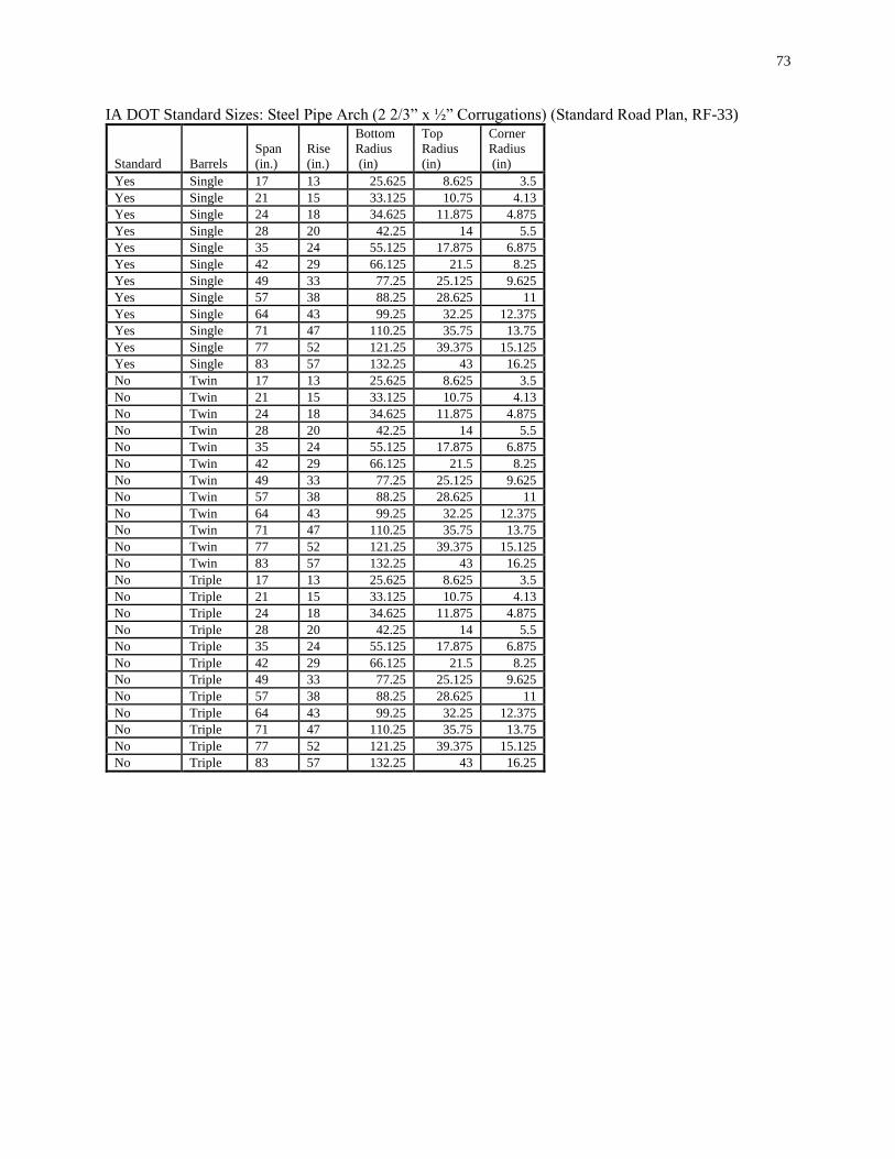
73
IA DOT Standard Sizes: Steel Pipe Arch (2 2/3” x ½” Corrugations) (Standard Road Plan, RF-33) Standard
Barrels
Span (in.)
Rise (in.)
Bottom Radius (in)
Top Radius (in)
Corner Radius (in)
Yes Single 17 13 25.625 8.625 3.5
Yes Single 21 15 33.125 10.75 4.13 Yes Single 24 18 34.625 11.875 4.875
Yes Single 28 20 42.25 14 5.5 Yes Single 35 24 55.125 17.875 6.875
Yes Single 42 29 66.125 21.5 8.25
Yes Single 49 33 77.25 25.125 9.625 Yes Single 57 38 88.25 28.625 11
Yes Single 64 43 99.25 32.25 12.375 Yes Single 71 47 110.25 35.75 13.75
Yes Single 77 52 121.25 39.375 15.125 Yes Single 83 57 132.25 43 16.25
No Twin 17 13 25.625 8.625 3.5
No Twin 21 15 33.125 10.75 4.13 No Twin 24 18 34.625 11.875 4.875
No Twin 28 20 42.25 14 5.5 No Twin 35 24 55.125 17.875 6.875
No Twin 42 29 66.125 21.5 8.25
No Twin 49 33 77.25 25.125 9.625 No Twin 57 38 88.25 28.625 11
No Twin 64 43 99.25 32.25 12.375 No Twin 71 47 110.25 35.75 13.75
No Twin 77 52 121.25 39.375 15.125 No Twin 83 57 132.25 43 16.25
No Triple 17 13 25.625 8.625 3.5
No Triple 21 15 33.125 10.75 4.13 No Triple 24 18 34.625 11.875 4.875
No Triple 28 20 42.25 14 5.5 No Triple 35 24 55.125 17.875 6.875
No Triple 42 29 66.125 21.5 8.25 No Triple 49 33 77.25 25.125 9.625
No Triple 57 38 88.25 28.625 11
No Triple 64 43 99.25 32.25 12.375 No Triple 71 47 110.25 35.75 13.75
No Triple 77 52 121.25 39.375 15.125 No Triple 83 57 132.25 43 16.25
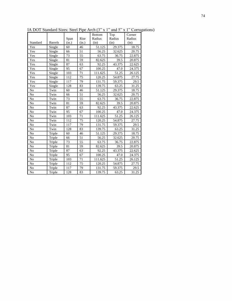
74
IA DOT Standard Sizes: Steel Pipe Arch (3” x 1” and 5” x 1” Corrugations) Standard
Barrels
Span (in.)
Rise (in.)
Bottom Radius (in)
Top Radius (in)
Corner Radius (in)
Yes Single 60 46 51.125 29.375 18.75
Yes Single 66 51 56.25 32.625 20.75 Yes Single 73 55 63.75 36.75 22.875
Yes Single 81 59 82.625 39.5 20.875 Yes Single 87 63 92.25 43.375 22.625
Yes Single 95 67 100.25 47.0 24.375
Yes Single 103 71 111.625 51.25 26.125 Yes Single 112 75 120.25 54.875 27.75
Yes Single 117 79 131.75 59.375 29.5 Yes Single 128 83 139.75 63.25 31.25
No Twin 60 46 51.125 29.375 18.75 No Twin 66 51 56.25 32.625 20.75
No Twin 73 55 63.75 36.75 22.875
No Twin 81 59 82.625 39.5 20.875 No Twin 87 63 92.25 43.375 22.625
No Twin 95 67 100.25 47.0 24.375 No Twin 103 71 111.625 51.25 26.125
No Twin 112 75 120.25 54.875 27.75
No Twin 117 79 131.75 59.375 29.5 No Twin 128 83 139.75 63.25 31.25
No Triple 60 46 51.125 29.375 18.75 No Triple 66 51 56.25 32.625 20.75
No Triple 73 55 63.75 36.75 22.875 No Triple 81 59 82.625 39.5 20.875
No Triple 87 63 92.25 43.375 22.625
No Triple 95 67 100.25 47.0 24.375 No Triple 103 71 111.625 51.25 26.125
No Triple 112 75 120.25 54.875 27.75 No Triple 117 79 131.75 59.375 29.5
No Triple 128 83 139.75 63.25 31.25

75
Appendix M: NE Scour Hole Design Methodology
The equations used to determine the basin size for the NE Scour Hole design are described
below.
The Nebraska (NE) scour hole design methodology and the following discussion is taken from
the Nebraska Department of Roads, Roadway Design Manual, chapter Five: Erosion and
Sedimentation Control, with reference to 5.5.27.1 Scour Hole.
A scour hole is a preformed excavated hole or depression which is lined with riprap of a stable
size to prevent scouring. The depression provides both vertical and lateral expansion downstream
of the culvert outlet to permit dissipation of excessive energy. A significant reduction in the size
of the riprap stone is achieved by the excavation.
Two types of preformed scour holes can be constructed. The first type of scour hole is depressed
one-half of the culvert diameter (or span). The second type is depressed the full culvert diameter
(or span). The design of preformed scour holes is based upon research conducted by the U.S.
Army Corps of Engineers.
Empirical equations developed for the hydraulic design of preformed scour holes are presented
below. Equations are applicable to both circular and rectangular culverts flowing full or partly
full. The software uses the equations shown to calculate the basin dimensions.
For a scour hole depressed ½ the culvert span:
𝐷50 = (0.0275𝐷𝑜
2
𝑇𝑊)(
𝑄
𝐷𝑜2.5)
4/3
in English units,
𝐷50 = (0.0125𝐷𝑜
2
𝑇𝑊)(
𝑄
𝐷𝑜2.5)
4/3
where:
D50 = Minimum average stone diameter required for scour holes depressed one-half the culvert
span, meter (ft)
D0 = culvert diameter or span, meter (ft)
TW = tail water depth above culvert invert, meter (ft)
Q = discharge, m3/s (ft3/s)

76
For a scour hole depressed the full culvert span use:
𝐷50 = (0.0181𝐷𝑜
2
𝑇𝑊)(
𝑄
𝐷𝑜2.5)
4/3
in English units:
𝐷50 = (0.0082𝐷𝑜
2
𝑇𝑊)(
𝑄
𝐷𝑜2.5)
4/3
where:
D50 = Minimum average stone diameter required for scour holes depressed the full culvert span,
meter (ft)
Dimensions for a scour hole basin are shown in the NE Scour Hole Plot, and are determined
from:
A = 2D0 + 6F
C = 3D0 + 6F
D = 2D50
E = D0
F = 0.5D0 or D0
Where:
A = basin inlet width and basin outlet width, meter (ft)
C = basin length, meter (ft)
D = thickness of riprap lining, meter (ft)
E = culvert diameter or span, meter (ft)
F = basin depression, meter (ft).

77
Appendix N: NE Plunge Basin The following table used for determining dimensions for the NE Plunge Basin is adapted from the Roadway Design
Manual, Nebraska Department of Roads, Chapter Five, Table 5.9 Plunge Basin Dimensions, page 5-43, December
1996.
Pipe Diameter
mm
(inches)
Basin Dimensions, m (ft)
V ≤ 5.5 m/s (18 fps) 5.5 m/s (18 fps) < V ≤
7.3 m/s (24 fps)
7.3 m/s (24 fps) < V ≤
9.1 m/s (30 fps)
A C E T F A C E T F A C E T F
600
(24)
1
(3)
0.5
(1.5)
1
(3)
0.5
(1.5)
1.2
(4)
1
(3)
0.5
(1.5)
1.5
(5)
0.5
(1.5)
1.2
(4)
1.2
(4)
0.6
(2)
2.1
(7)
0.5
(1.5)
1.2
(4)
750
(30)
1
(3)
0.5
(1.5)
1
(3)
0.6
(2)
1.2
(4)
1
(3)
0.5
(1.5)
1.5
(5)
0.6
(2)
1.2
(4)
1.2
(4)
0.6
(2)
2.1
(7)
0.6
(2)
1.2
(4)
900
(36)
1
(3)
0.5
(1.5)
1
(3)
0.8
(2.5)
1.5
(5)
1
(3)
0.5
(1.5)
1.5
(5)
0.8
(2.5)
1.5
(5)
1.2
(4)
0.6
(2)
2.1
(7)
0.8
(2.5)
1.5
(5)
1050
(42)
1
(3)
0.5
(1.5)
1
(3)
1
(3)
1.5
(5)
1
(3)
0.5
(1.5)
1.5
(5)
1
(3)
1.5
(5)
1.2
(4)
0.6
(2)
2.1
(7)
1
(3)
1.5
(5)
1200
(48)
1
(3)
0.5
(1.5)
1
(3)
1
(3)
1.8
(6)
1.2
(4)
0.6
(2)
1.5
(5)
1
(3)
1.8
(6)
1.5
(5)
0.8
(2.5)
2.1
(7)
1
(3)
1.8
(6)
1350
(54)
1
(3)
0.5
(1.5)
1
(3)
1.2
(4)
2.1
(7)
1.2
(4)
0.6
(2)
1.5
(5)
1.2
(4)
2.1
(7)
1.5
(5)
0.8
(2.5)
2.1
(7)
1.2
(4)
2.1
(7)
1500
(60)
1.2
(4)
0.6
(2)
1
(3)
1.2
(4)
2.4
(8)
1.2
(4)
0.6
(2)
1.5
(5)
1.2
(4)
2.4
(8)
1.8
(6)
1
(3)
2.1
(7)
1.2
(4)
2.4
(8)
1650
(66)
1.2
(4)
0.6
(2)
1
(3)
1.5
(5)
2.4
(8)
1.5
(5)
0.8
(2.5)
1.5
(5)
1.5
(5)
2.4
(8)
1.8
(6)
1
(3)
2.1
(7)
1.5
(5)
2.4
(8)
1800
(72)
1.2
(4)
0.6
(2)
1
(3)
1.5
(5)
2.7
(9)
1.5
(5)
0.8
(2.5)
1.5
(5)
1.5
(5)
2.7
(9)
1.8
(6)
1
(3)
2.1
(7)
1.5
(5)
2.7
(9)
2100
(84)
1.5
(5)
0.8
(2.5)
1
(3)
1.7
(5.5)
3.4
(11)
1.8
(6)
1
(3)
1.5
(5)
1.7
(5.5)
3.4
(11)
2.1
(7)
1.1
(3.5)
2.1
(7)
1.7
(5.5)
3.4
(11)
2400
(96)
1.8
(6)
1
(3)
1
(3)
1.8
(6)
3.7
(12)
2.1
(7)
1.1
(3.5)
1.5
(5)
1.8
(6)
3.7
(12)
2.4
(8)
1.2
(4)
2.1
(7)
1.8
(6)
3.7
(12)
Riprap Dimensions, mm (inches)
Riprap
Size
Riprap
Thickness
Riprap
Size
Riprap
Thickness
Riprap
Size
Riprap
Thickness
400
(16)
500
(16)
600
(24)
600
(24)
600
(24)
Class B
750
(30)
Values used by IA Culvert Software
(12)
Class E
(24) (18)
Class B
(36) (18)
Class B
(36)

78
Appendix O: Hec-14 Riprap Basin
The design methods used for the Hec-14 Riprap Basin are based on methods from Hydraulic
Engineering Circular No. 14 (Hec-14), Hydraulic Design of Energy Dissipators for Culvers and
Channels, U.S. Department of Transportation, Federal Highway Administration, September
1983. For details on the derivation of the methodology please see the above manual, in particular
Chapter XI. You can download a copy of the Hec-14 manual at
http://www.fhwa.dot.gov/bridge/hydpub.htm.
General details of the HEC-14 Riprap Basin are shown on the Hec-14 Riprap Basin Design Plot.
The general design approach used by the method is:
The critical depth and normal depth for the culvert are determined.
Brink depth: Yo
If the culvert flow conditions are hydraulically steep (supercritical flow), the brink depth (Yo) is
determined using normal depth, or the tailwater depth, whichever is larger. If the tailwater depth
exceeds the culvert rise, the brink depth is the culvert rise.
If the culvert flow is not hydraulically steep (subcritical flow), figure III-9 or III-10 from Hec-14
(shown below as Figures 1 and 2) are used to find Yo/D, where D is the culvert span. There is
not an equivalent figure in Hec 14 for arch pipes. For arch pipes, critical depth is used for Yo.
Brink Flow Area:
The brink flow area is determined from the culvert geometry and the brink depth.
Exit velocity: Vo
The exit velocity is the design Q divided by the Brink Flow area.
Equivalent Brink Depth: Ye
For rectangular culverts, Ye=Yo.
For non-rectangular culverts, Ye=(A/2)1/2, where A is the Brink Flow Area.
Froude Number
The Froude Number is determined as
Froude Number = 𝑉𝑜
√32.2𝑌𝑒

79
Finding d50
Using the value of Ye and the Froude Number, finding an acceptable combination of d50
(median riprap size) and hs (the depth of the riprap basin) is a trial and error process.
The process is:
Guess a d50 value. Compute d50/Ye. Using figure XI-2 of Hec 14 (shown as figure 3 below),
find the ratio of hs/Ye. Compute hs. Compute the ratio of hs/d50. If the ratio of hs/d50 is
between 2 and 4 the d50 is acceptable (according to Hec-14). If the ratio of hs/d50 is not between
2 and 4, try another value of d50.
The software automatically iterates through trial values of d50 to find a d50 such that hs/d50 is
between 2 and 4, if one exists. The software tries d50 values in 0.1 foot increments. If more than
one value of d50 results in a value of hs/d50 between 2 and 4, the d50 that results in hs/d50
closest to 3 is displayed as the solution.
Modification from Hec-14:
The software uses figure XI-2 from Hec-14 (Figure 3 below) in a modified manner. The lines on
the figure each apply to a range of d50/Ye, as shown. This can lead to a large change in the
hs/Ye value with a small change in d50/Ye (for example, d50/Ye of 0.3 versus 0.31). This can
also make it difficult to find a feasible hs/d50.
To address these problems, the software applies the midpoint of the range to each line on the
figure and uses linear interpolation to estimate values of hs/Ye.
For example:
the line for 0.21 ≤𝑑50
𝑌𝑒≤ 0.30 is assigned a value of d50/Ye=0.25
the line for 0.31 ≤𝑑50
𝑌𝑒≤ 0.40 is assigned a value of d50/Ye=0.35
For values of d50/Ye that fall between the values assigned to these 2 lines, vertical linear
interpolation is used to estimate the value of hs/Ye.
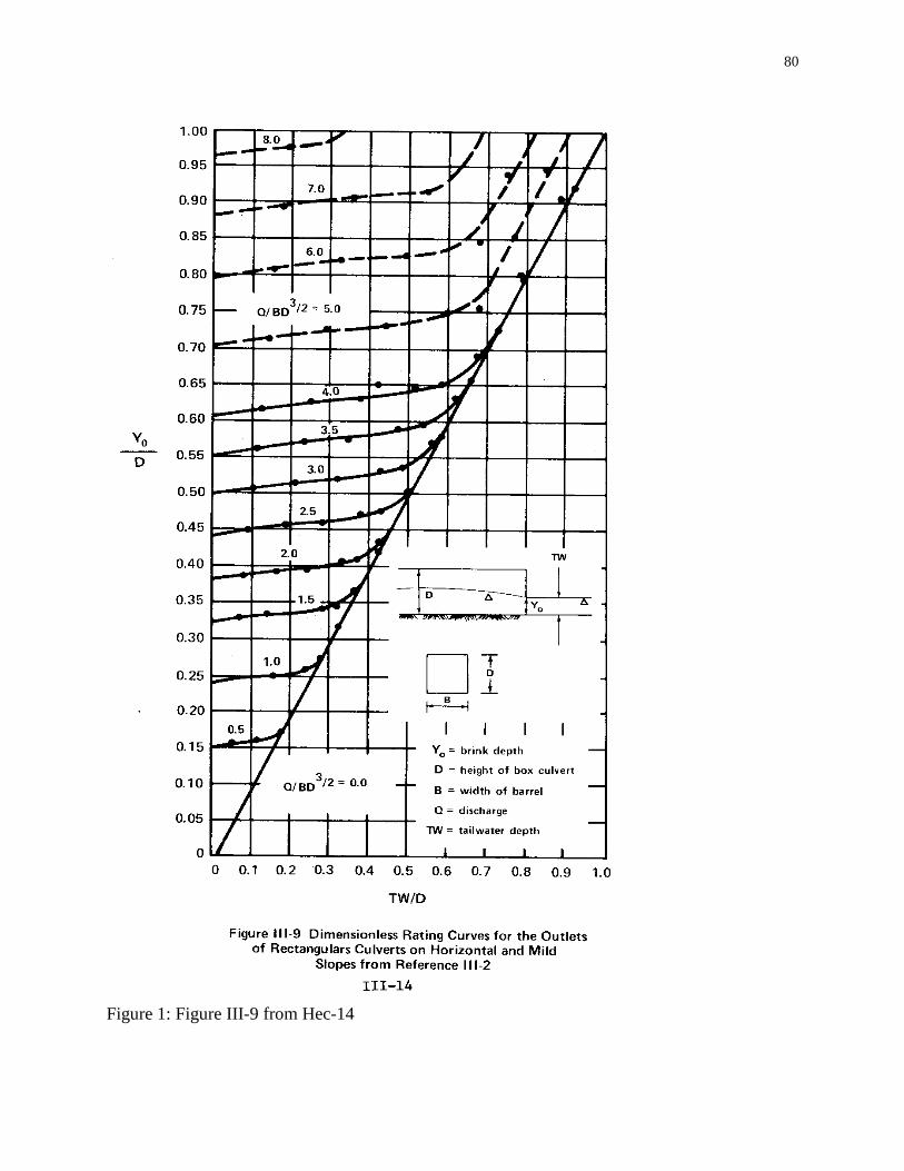
80
Figure 1: Figure III-9 from Hec-14
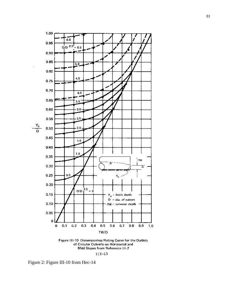
81
Figure 2: Figure III-10 from Hec-14
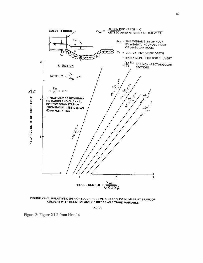
82
Figure 3: Figure XI-2 from Hec-14