ION ENERGY AND ANGULAR DISTRIBUTIONS INTO SMALL FEATURES IN PLASMA ETCHING REACTORS: THE WAFER-...
20
ION ENERGY AND ANGULAR DISTRIBUTIONS INTO SMALL FEATURES IN PLASMA ETCHING REACTORS: THE WAFER- FOCUS RING GAP* Natalia Yu. Babaeva and Mark J. Kushner Iowa State University Department of Electrical and Computer Engineering Ames, IA 50011, USA [email protected] [email protected] http://uigelz.ece.iastate.edu AVS 54 th International Symposium October 2007 * Work supported by Semiconductor Research Corp., Applied Materials and NSF AVS2007_Natalie_01
-
date post
21-Dec-2015 -
Category
Documents
-
view
219 -
download
2
Transcript of ION ENERGY AND ANGULAR DISTRIBUTIONS INTO SMALL FEATURES IN PLASMA ETCHING REACTORS: THE WAFER-...
ION ENERGY AND ANGULAR DISTRIBUTIONS INTO SMALL FEATURES IN PLASMA ETCHING
REACTORS:THE WAFER- FOCUS RING GAP*
Natalia Yu. Babaeva and Mark J. Kushner
Iowa State UniversityDepartment of Electrical and Computer Engineering
Ames, IA 50011, USA [email protected] [email protected]
http://uigelz.ece.iastate.edu
AVS 54th International Symposium
October 2007
* Work supported by Semiconductor Research Corp., Applied Materials and NSF
AVS2007_Natalie_01

Iowa State UniversityOptical and Discharge Physics
AGENDA
Wafer edge effects
Description of the model
Ion energy and angular distribution on different surfaces in wafer-focus ring gap for focus ring:
Capacitance Height Conductivity
Concluding remarks
AVS2007_Natalie_02

Iowa State UniversityOptical and Discharge Physics
Orientation of electric field and ion trajectories, energy and angular distributions depend on details of the geometry and materials.
AVS2007_Natalie_03
Gap (< 1 mm) between wafer and focus ring in plasma tools for mechanical clearance.
Beveled wafers allow for “under wafer” plasma-surface processes.
Penetration of plasma into gap can deposit of contaminating films.
PENETRATION OF PLASMA INTO WAFER-FOCUS RING GAP

Iowa State UniversityOptical and Discharge PhysicsAVS2007_Natalie_03
The ion energy and angular distributions (IEADs) into the wafer-focus ring gap are important;
Angular distribution determines erosion (e.g., maximum sputtering at 60o.
Time between replacement of consumable parts depends on erosion.
Spacing, materials (e.g., dielectric constant, conductivity) determine electric field in gap and so IEADS.
In this presentation, results from a computational investigation of IEADs onto surfaces in wafer-focus ring gap will be discussed.
Model: nonPDPSIM using unstructured meshes.
Goal: How does one control the IEADs?
INVESTIGATION OF IEADs INTO WAFER-FOCUS RING GAP

nonPDPSIM: BASIC EQUATIONS
Poisson equation: Electric potential
Transport of charged species j
Surface charge balance
Full momentum for ion fluxes
Neutral transport: Navier-Stokes equations.
Improvements to include Monte Carlo simulation of Ion Energy and Angular distributions (IEADs).
)( j
jj Nq
St
N j
materialj
j Sqt
iji
ijjj
jjj
jjj
j vvNM
ENqP
Mv
t
1
Iowa State UniversityOptical and Discharge PhysicsAVS2007_Natalie_04

MESHING TO RESOLVE FOCUS RING GAP
Iowa State UniversityOptical and Discharge PhysicsAVS2007_Natalie_05
2-dimensional model using an unstructured mesh to resolve wafer-focus ring gaps of < 1 mm.
Numbering indicates materials and locations on which IEADs are obtained.
Ar, 10 MHz, 100 mTorr, 300 V, 300 sccm

POTENTIAL, ELECTRIC FIELD, IONS
Iowa State UniversityOptical and Discharge PhysicsMIN MAX
E/N
Potential
[Ar+]
AVS2007_Natalie_06
Off-axis maximum in [Ar+] is due to electric field enhancement near focus ring and is uncorrelated to gap.
Ar, 10 MHz, 100 mTorr, 300 V
Gap: 1 mm

Iowa State UniversityOptical and Discharge Physics
POTENTIAL AND CHARGES (RF CYCLE)
1.0 mm Gap
Animation Slide
AVS2007_Natalie_07
-1.1 x 1011 cm-3
Highly conductive wafer with small capacitance charges and discharges rapidly.
Focus ring acquires larger negative surface charges. Large potential drop in focus ring.
MIN MAX Log scale
Surface Charges Cycle averaged potential
Powered Electrode Powered Electrode

Iowa State UniversityOptical and Discharge Physics
Directions of electric fields near surfaces evolve slowly during rf
cycle due to slowly changing surface charge.
Direction of ion fluxes changes during rf cycle from nearly vertical to perpendicular to surface with transients in electric field.
ION FLUX VECTORS (RF CYCLE)
AVS2007_Natalie_08
1.0 mm Gap
Animation Slide
Powered Electrode

Iowa State UniversityOptical and Discharge PhysicsAVS2007_Natalie_09
ION ENERGY AND ANGULAR DISTRIBUTIONS
Broad IEAD on top bevel due to ions arriving during positive and negative parts of rf cycle.
Grazing angles for ions striking vertical surfaces.
MIN MAX Log scale

Iowa State UniversityOptical and Discharge Physics
Cathodic cycle:
High energy ions at grazing incident on side wall.
Near vertical to bevel.
Anodic rf cycle:
Low energy ions near vertical on side wall.
High energy angles a large angle to bevel.
ION FLUXES AT DIFFERENT PHASE OF RF CYCLE
AVS2007_Natalie_10
1.0 mm Gap
9
9
MIN MAX Log scale
Cathodic rf cycle
5
5
Anodic rf cycle

Iowa State UniversityOptical and Discharge PhysicsMIN MAX
Log scale
Wafer charges quickly (almost anti-phase with focus ring).
More surface charges collected on focus ring with larger capacitance.
Ions penetrate into gap throughout rf cycle with larger capacitance.
AVS2007_Natalie_11
1.0 mm Gap
Ar+
0.5 mm GapAnimation Slide
-7.8 x 1010 cm-3
Ar+
/o= 4 /o= 20
CAPACITANCE OF FOCUS RING: ION DENSITY AND CHARGES
Powered electrode Powered electrode
Powered electrode Powered electrode
-1.2 x 1011 cm-3

Iowa State UniversityOptical and Discharge Physics
MIN MAX Log scale
AVS2007_Natalie_12
/o= 4
/o= 20
CAPACITANCE OF FOCUS RING: IEAD
Penetration of potential into focus ring with low capacitance produces lateral E-field.
IEAD on substrate is asymmetric.
Iowa State UniversityOptical and Discharge PhysicsMIN MAX
Log scale
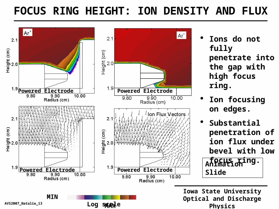
Ions do not fully penetrate into the gap with high focus ring.
Ion focusing on edges.
Substantial penetration of ion flux under bevel with low focus ring.
FOCUS RING HEIGHT: ION DENSITY AND FLUX
1.0 mm Gap
AVS2007_Natalie_13
Animation Slide
Powered Electrode Powered Electrode
Powered Electrode Powered Electrode

Iowa State UniversityOptical and Discharge Physics
1.0 mm Gap 0.25 mm Gap
AVS2007_Natalie_14
“Open” edge produces skewed IEADsMIN MAX
Log scale
FOCUS RING HEIGHT: IEAD

Iowa State UniversityOptical and Discharge Physics
Configuration of wafer-focus ring gap can be used to control IEADS.
Example: Extension of biased substrate under dielectric focus ring of differing conductivity.
DESIGN TO CONTROL IEADs
AVS2007_Natalie_15

Iowa State UniversityOptical and Discharge Physics
Same conductivity wafer and FR.
More uniform and symmetric sheath and plasma parameters.
0.1 Ohm-1 cm-1
MIN MAX Log scale
EXTENDED ELECTRODE : CHARGE, E-FIELD AND ION FLUX
Animation Slide
AVS2007_Natalie_16
Powered Electrode
Powered ElectrodePowered Electrode

Iowa State UniversityOptical and Discharge Physics
AVS2007_Natalie_17
On all surfaces more narrow and symmetric IEAD with uniform electrical boundary condition.
Wafer: 0.1 Ohm-1 cm-1
Ring: 10-8 Ohm-1 cm-1
Wafer and Ring: 0.1 Ohm-1 cm-1
EXTENDED ELECTRODE: IEAD
MIN MAX Log scale

Iowa State UniversityOptical and Discharge Physics
MIN MAX Log scale
Always broad and asymmetric IEAD on tilted surface.
FR Conductivity
BROADENING OF IEAD ON TOP BEVEL: EFFECT OF FR
/o= 4 /o= 20 High FR Low FR
AVS2007_Natalie_18

CONCLUDING REMARKS
Ion energy and angular distributions were investigated on surfaces inside wafer-focus ring gap.
Different regions of the IEADs are generated during different parts of the rf cycle. Even vertical surfaces receive some normal angle ion flux.
Narrow IEAD are obtained with
High focus ring
High focus ring capacitance
High focus ring conductivity.
Uniform electrical boundary conditions leads to more symmetric sheath over the gap and narrows IEADs.
On tilted surfaces broad and asymmetric IEADs are obtained for most conditions.
Iowa State UniversityOptical and Discharge Physics
AVS2006_Natalie_19