ion & Control Eng'g
106
Instrumentation engineering Instrumentation engineering Instrumentation engineering Instrumentation engineering is the is the engineering speci alization focused on the engineering speci alization focused on the principle and operation of measuring principle and operation of measuring instruments w hich are used in design and instruments w hich are used in design and configuration of automated sy stems in configuration of automated sy stems in electrical, pneuma tic domains etc. They electrical, pneuma tic domains etc. They typically work for industries with typically work for industries with automated automated processes, such as processes, such as chemical chemical or or manufacturing manufacturing plants, with the goal of plants, with the goal of improving system improving system productivity productivity, reliability, , reliability, safety, optimization, and stability. safety, optimization, and stability.
-
Upload
mark-de-guzman -
Category
Documents
-
view
230 -
download
0
Transcript of ion & Control Eng'g

8/3/2019 ion & Control Eng'g
http://slidepdf.com/reader/full/ion-control-engg 1/106
Instrumentation engineeringInstrumentation engineering
Instrumentation engineeringInstrumentation engineering is theis the
engineering specialization focused on theengineering specialization focused on the
principle and operation of measuringprinciple and operation of measuring
instruments which are used in design andinstruments which are used in design and
configuration of automated systems inconfiguration of automated systems inelectrical, pneumatic domains etc. Theyelectrical, pneumatic domains etc. They
typically work for industries withtypically work for industries with automatedautomated
processes, such asprocesses, such as chemicalchemical or or manufacturingmanufacturing plants, with the goal of plants, with the goal of
improving systemimproving system productivityproductivity, reliability,, reliability,
safety, optimization, and stability.safety, optimization, and stability.
8/3/2019 ion & Control Eng'g
http://slidepdf.com/reader/full/ion-control-engg 2/106
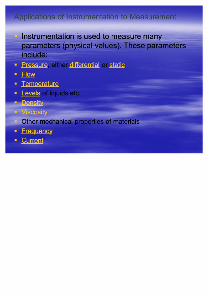
Applications of Instrumentation to Measurement Applications of Instrumentation to Measurement
Instrumentation is used to measure manyInstrumentation is used to measure manyparameters (physical values). These parametersparameters (physical values). These parameters
include:include:
PressurePressure, either , either differentialdifferential or or staticstatic
FlowFlow
TemperatureTemperature
LevelsLevels of liquids etc.of liquids etc.
DensityDensity
ViscosityViscosity
Other mechanical properties of materialsOther mechanical properties of materials
FrequencyFrequency
CurrentCurrent
8/3/2019 ion & Control Eng'g
http://slidepdf.com/reader/full/ion-control-engg 3/106
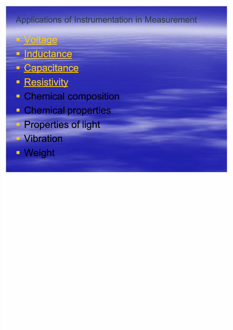
Applications of Instrumentation in Measurement Applications of Instrumentation in Measurement
VoltageVoltage InductanceInductance
CapacitanceCapacitance
ResistivityResistivity Chemical compositionChemical composition
Chemical propertiesChemical properties
Properties of lightProperties of light
VibrationVibration
WeightWeight
8/3/2019 ion & Control Eng'g
http://slidepdf.com/reader/full/ion-control-engg 4/106
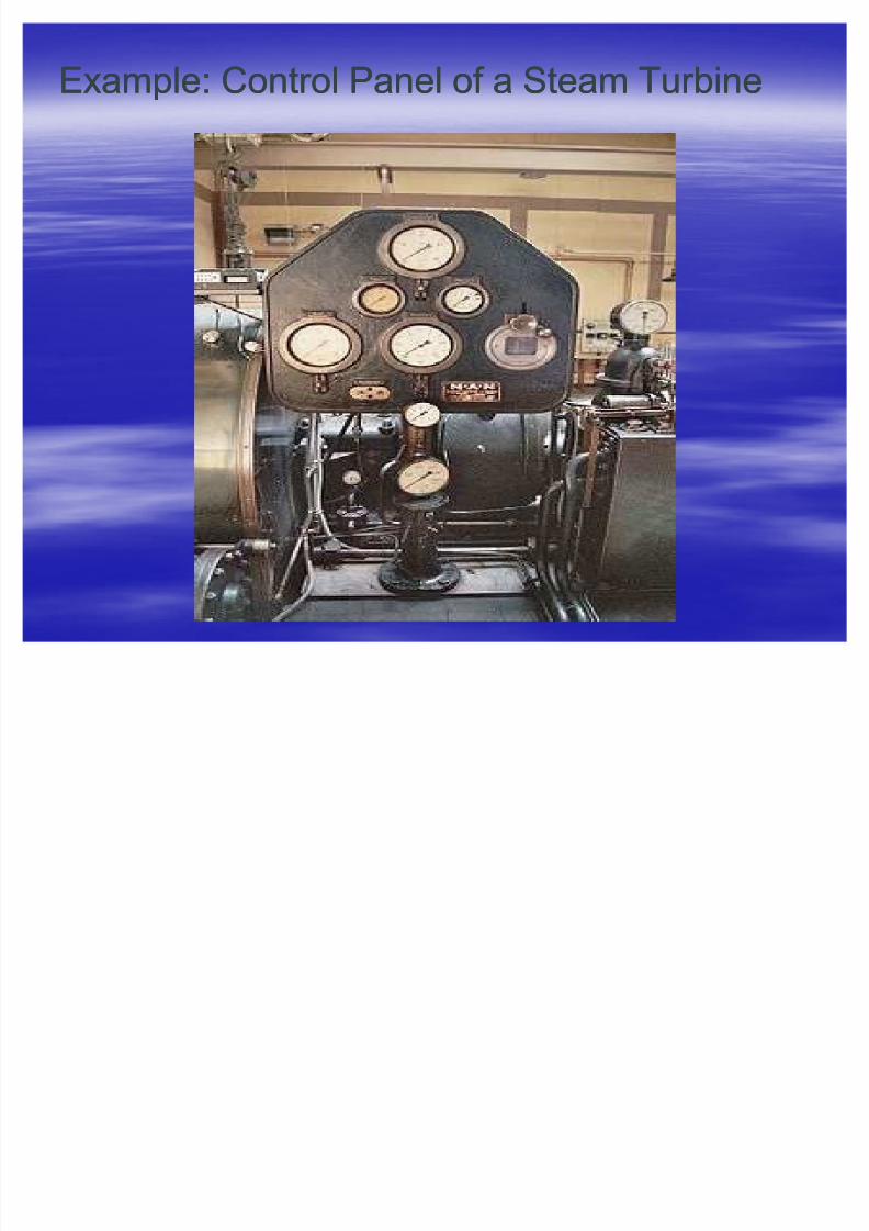
Example: Control Panel of a Steam TurbineExample: Control Panel of a Steam Turbine

8/3/2019 ion & Control Eng'g
http://slidepdf.com/reader/full/ion-control-engg 5/106
Instrumentation EngineeringInstrumentation Engineering
Instrumentation engineeringInstrumentation engineering deals with thedeals with thedesign of devices to measure physicaldesign of devices to measure physical
quantities such asquantities such as pressure, flow andpressure, flow and
temperaturetemperature. The design of such. The design of suchinstrumentation requires a goodinstrumentation requires a good
understanding of understanding of physicsphysics that often extendsthat often extends
beyondbeyond electromagnetic theoryelectromagnetic theory. For . For
example,example, thermocouplesthermocouples use theuse the Peltier Peltier--SeebeckSeebeck effecteffect to measure the temperatureto measure the temperature
difference between two points.difference between two points.

8/3/2019 ion & Control Eng'g
http://slidepdf.com/reader/full/ion-control-engg 6/106
Instrumentation EngineeringInstrumentation Engineering
Often instrumentation is not used by itself,Often instrumentation is not used by itself,
but instead as thebut instead as the sensorssensors of larger of larger
electrical systems. For example, aelectrical systems. For e
xample, athermocouple might be used to help ensurethermocouple might be used to help ensure
a furnace's temperature remains constant.a furnace's temperature remains constant.
For this reason, instrumentation engineeringFor this reason, instrumentation engineering
is often viewed as the counterpart of controlis often viewed as the counterpart of controlengineeringengineering

8/3/2019 ion & Control Eng'g
http://slidepdf.com/reader/full/ion-control-engg 7/106
Instrumentation engineeringInstrumentation engineering
An instrument is a device that measures An instrument is a device that measures
and/or regulates process variables such asand/or regulates process variables such as
flow, temperature, level, or pressure.flow, temperature, level, or pressure.Instruments include many variedInstruments include many varied
contrivances which can be as simple ascontrivances which can be as simple as
valvesvalves andand transmitterstransmitters, and as complex as, and as complex as
analyzersanalyzers. Instruments often comprise. Instruments often comprisecontrol systems of varied processes such ascontrol systems of varied processes such as
refineries, factories, and vehicles.refineries, factories, and vehicles.

8/3/2019 ion & Control Eng'g
http://slidepdf.com/reader/full/ion-control-engg 8/106
Instrumentation engineeringInstrumentation engineering
The control of processes is one of the mainThe control of processes is one of the main
branches of applied instrumentation.branches of applied instrumentation.
The control of the parameters in a processThe control of the parameters in a processor in a particular system, are made possibleor in a particular system, are made possible
by using devices such as microprocessors,by using devices such as microprocessors,
microcontrollers or PLCs, but their ultimatemicrocontrollers or PLCs, but their ultimate
aim is to control the parameters of a system.aim is to control the parameters of a system.

8/3/2019 ion & Control Eng'g
http://slidepdf.com/reader/full/ion-control-engg 9/106
Instrumentation engineeringInstrumentation engineering
Output instrumentation includes devices such asOutput instrumentation includes devices such assolenoidssolenoids,, valvesvalves,, regulatorsregulators,, circuit breakerscircuit breakers, and, and
relaysrelays. These devices control a desired output. These devices control a desired output
variable, and provide either remote or automatedvariable, and provide either remote or automated
control capabilities. These are often referred to ascontrol capabilities. These are often referred to asfinal control elements when controlled remotely or final control elements when controlled remotely or
by aby a control systemcontrol system..
Control Instrumentation plays a significant role inControl Instrumentation plays a significant role in
both gathering information from the field andboth gathering information from the field and
changing the field parameters, and as such are achanging the field parameters, and as such are a
key part of key part of control loopscontrol loops..
8/3/2019 ion & Control Eng'g
http://slidepdf.com/reader/full/ion-control-engg 10/106
Instrumentation engineeringInstrumentation engineering
TransmittersTransmitters are devices which produce an outputare devices which produce an outputsignal, often in the form of a 4signal, often in the form of a 4± ±2020 m Am A electricalelectrical
currentcurrent signal, although many other options usingsignal, although many other options using
voltagevoltage,, frequencyfrequency,, pressurepressure, or , or ethernetethernet areare
possible. This signal can be used for informationalpossible. This signal can be used for informationalpurposes, or it can be sent to apurposes, or it can be sent to a PLCPLC,, DCSDCS,, SC AD ASC AD A
system, or other type of computerized controller,system, or other type of computerized controller,
where it can be interpreted into readable values andwhere it can be interpreted into readable values and
used to control other devices and processes in theused to control other devices and processes in thesystem.system.
8/3/2019 ion & Control Eng'g
http://slidepdf.com/reader/full/ion-control-engg 11/106
Instrumentation engineeringInstrumentation engineering
A A programmable logic controller programmable logic controller ((PLCPLC) or ) or programmable controller programmable controller is ais a digital computer digital computer used for used for
automationautomation of of electromechanicalelectromechanical processes, such asprocesses, such as
control of machinery on factorycontrol of machinery on factory assembly linesassembly lines,,
amusement rides, or lighting fixtures. Unlike generalamusement rides, or lighting fixtures. Unlike general--
purpose computers, the PLC is designed for multiple inputspurpose computers, the PLC is designed for multiple inputs
and output arrangements, extended temperature ranges,and output arrangements, extended temperature ranges,
immunity to electrical noise, and resistance to vibration andimmunity to electrical noise, and resistance to vibration and
impact. Programs to control machine operation areimpact. Programs to control machine operation are
typically stored in batterytypically stored in battery--backed or backed or nonnon--volatile memoryvolatile memory. A . A PLC is an example of aPLC is an example of a real timereal time system since outputsystem since output
results must be produced in response to input conditionsresults must be produced in response to input conditions
within a bounded time, otherwise unintended operation willwithin a bounded time, otherwise unintended operation will
result.result.

8/3/2019 ion & Control Eng'g
http://slidepdf.com/reader/full/ion-control-engg 12/106
Instrumentation engineeringInstrumentation engineering
ProgrammingProgramming
PLC programs are typically written in aPLC programs are typically written in a
special application on a personal computer,special application on a personal computer,
then downloaded by a directthen downloaded by a direct--connectionconnectioncable or over a network to the PLC. Thecable or over a network to the PLC. The
program is stored in the PLC either inprogram is stored in the PLC either in
batterybattery--backedbacked--upup R AMR AM or some other nonor some other non--
volatilevolatile flash memoryflash memory. Often, a single PLC. Often, a single PLC
can be programmed to replace thousands of can be programmed to replace thousands of
relaysrelays..
8/3/2019 ion & Control Eng'g
http://slidepdf.com/reader/full/ion-control-engg 13/106
Instrumentation engineeringInstrumentation engineering
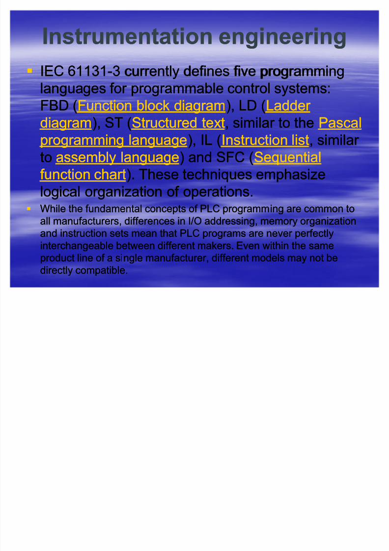
IEC 61131IEC 61131--3 currently defines five programming3 currently defines five programminglanguages for programmable control systems:languages for programmable control systems:
FBD (FBD (Function block diagramFunction block diagram), LD (), LD (Ladder Ladder
diagramdiagram), ST (), ST (Structured textStructured text, similar to the, similar to the PascalPascal
programming languageprogramming language), IL (), IL (Instruction listInstruction list, similar , similar toto assembly languageassembly language) and SFC () and SFC (SequentialSequential
function chartfunction chart). These techniques emphasize). These techniques emphasize
logical organization of operations.logical organization of operations. While the fundamental concepts of PLC programming are common toWhile the fundamental concepts of PLC programming are common to
all manufacturers, differences in I/O addressing, memory organizationall manufacturers, differences in I/O addressing, memory organization
and instruction sets mean that PLC programs are never perfectlyand instruction sets mean that PLC programs are never perfectly
interchangeable between different makers. Even within the sameinterchangeable between different makers. Even within the same
product line of a single manufacturer, different models may not beproduct line of a single manufacturer, different models may not be
directly compatible.directly compatible.
8/3/2019 ion & Control Eng'g
http://slidepdf.com/reader/full/ion-control-engg 14/106
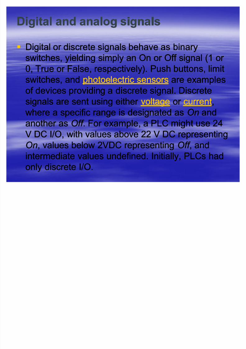
Digital andDigital and analoganalog signalssignals
Digital or discrete signals behave as binaryDigital or discrete signals behave as binaryswitches, yielding simply an On or Off signal (1 or switches, yielding simply an On or Off signal (1 or
0, True or False, respectively). Push buttons, limit0, True or False, respectively). Push buttons, limit
switches, andswitches, and photoelectric sensorsphotoelectric sensors are examplesare examples
of devices providing a discrete signal. Discreteof devices providing a discrete signal. Discrete
signals are sent using either signals are sent using either voltagevoltage or or currentcurrent,,
where a specific range is designated aswhere a specific range is designated as OnOn andand
another asanother as Off Off . For example, a PLC might use 24. For example, a PLC might use 24
V DC I/O, with values above 22 V DC representingV DC I/O, with values above 22 V DC representing
OnOn, values below 2VDC representing, values below 2VDC representing Off Off , and, and
intermediate values undefined. Initially, PLCs hadintermediate values undefined. Initially, PLCs had
only discrete I/O.only discrete I/O.

8/3/2019 ion & Control Eng'g
http://slidepdf.com/reader/full/ion-control-engg 15/106
Digital andDigital and analoganalog signalssignals
Analog Analog signals are like volume controls, with a range of signals are like volume controls, with a range of values between zero and fullvalues between zero and full--scale. These are typicallyscale. These are typically
interpreted as integer values (counts) by the PLC, withinterpreted as integer values (counts) by the PLC, with
various ranges of accuracy depending on the device andvarious ranges of accuracy depending on the device and
the number of bits available to store the data. As PLCsthe number of bits available to store the data. As PLCs
typically use 16typically use 16--bit signed binary processors, the integer bit signed binary processors, the integer
values are limited betweenvalues are limited between --32,768 and +32,767. Pressure,32,768 and +32,767. Pressure,
temperature, flow, and weight are often represented bytemperature, flow, and weight are often represented by
analoganalog signals.signals. Analog Analog signals can usesignals can use voltagevoltage or or currentcurrent
with a magnitude proportional to the value of the processwith a magnitude proportional to the value of the processsignal. For example, ansignal. For example, an analoganalog 00 -- 1010 V input or V input or 44--2020 m Am A
would bewould be convertedconverted into an integer value of 0into an integer value of 0 -- 32767.32767.

8/3/2019 ion & Control Eng'g
http://slidepdf.com/reader/full/ion-control-engg 16/106
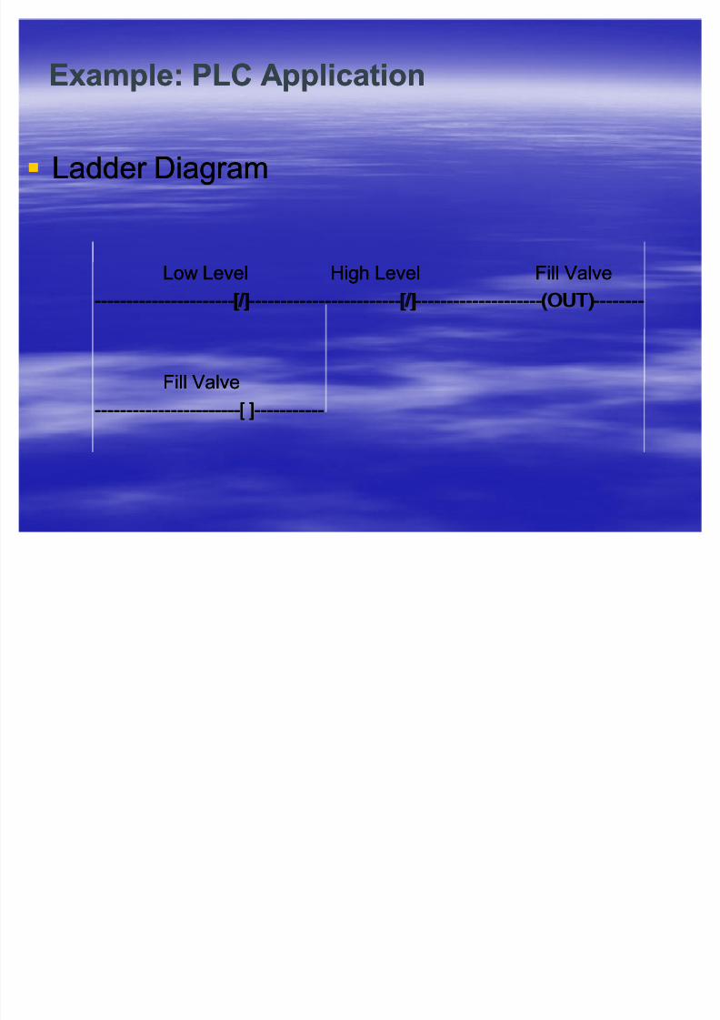
Example: PLC ApplicationExample: PLC Application
As an example, say a facility needs to store water As an example, say a facility needs to store water in a tank. The water is drawn from the tank byin a tank. The water is drawn from the tank by
another system, as needed, and our exampleanother system, as needed, and our example
system must manage the water level in the tank.system must manage the water level in the tank.
-- Using only digital signals, the PLC has two digitalUsing only digital signals, the PLC has two digitalinputs frominputs from float switchesfloat switches (Low Level and High(Low Level and High
Level). When the water level is above the switch itLevel). When the water level is above the switch it
closes a contact and passes a signal to an input.closes a contact and passes a signal to an input.
The PLC uses a digital output to open and closeThe PLC uses a digital output to open and closethe inletthe inlet valvevalve into the tank.into the tank.

8/3/2019 ion & Control Eng'g
http://slidepdf.com/reader/full/ion-control-engg 17/106
Example: PLC ApplicationExample: PLC Application
-- When the water level drops enough so thatWhen the water level drops enough so that
the Low Level float switch is off (down), thethe Low Level float switch is off (down), the
PLC will open the valve to let more water in.PLC will open the valve to let more water in.
Once the water level rises enough so thatOnce the water level rises enough so thatthe High Level switch is on (up), the PLC willthe High Level switch is on (up), the PLC will
shut the inlet to stop the water fromshut the inlet to stop the water from
overflowing. This rung is an example of overflowing. This rung is an example of sealseal--in (latching) logic. The output is sealedin (latching) logic. The output is sealed
in until some condition breaks the circuit.in until some condition breaks the circuit.
8/3/2019 ion & Control Eng'g
http://slidepdf.com/reader/full/ion-control-engg 18/106
Example: PLC ApplicationExample: PLC Application
Ladder DiagramLadder Diagram
Low LevelLow Level High Level Fill ValveHigh Level Fill Valve
--------------------------------------------[/][/]------------------------------------------------[/][/]----------------------------------------(OUT)(OUT)----------------
Fill ValveFill Valve
----------------------------------------------[ ][ ]----------------------

8/3/2019 ion & Control Eng'g
http://slidepdf.com/reader/full/ion-control-engg 19/106
Considerations:Considerations:
An An analoganalog system might use a water system might use a water pressure sensor pressure sensor or aor aload cellload cell, and an adjustable (throttling) dripping out of the, and an adjustable (throttling) dripping out of the
tank, the valve adjusts to slowly drip water back into the tank.tank, the valve adjusts to slowly drip water back into the tank.
In this system, to avoid 'flutter' adjustments that can wear outIn this system, to avoid 'flutter' adjustments that can wear out
the valve, many PLCs incorporate "the valve, many PLCs incorporate "hysteresishysteresis" which" whichessentially creates a "essentially creates a "deadbanddeadband" of activity. A technician" of activity. A technician
adjusts thisadjusts this deadbanddeadband so the valve moves only for aso the valve moves only for a
significant change in rate. This will in turn minimize the motionsignificant change in rate. This will in turn minimize the motion
of the valve, and reduce its wear.of the valve, and reduce its wear.
A real system might combine both approaches, using float A real system might combine both approaches, using floatswitches and simple valves to prevent spills, and a rateswitches and simple valves to prevent spills, and a rate
sensor and rate valve to optimize refill rates and preventsensor and rate valve to optimize refill rates and prevent
water hammer water hammer . Backup and maintenance methods can make. Backup and maintenance methods can make
a real system very complicated.a real system very complicated.

8/3/2019 ion & Control Eng'g
http://slidepdf.com/reader/full/ion-control-engg 20/106
Instrumentation engineeringInstrumentation engineering
A A distributed control systemdistributed control system (DCS) refers to a(DCS) refers to a controlcontrolsystemsystem usually of ausually of a manufacturing systemmanufacturing system,, processprocess or anyor any
kind of kind of dynamic systemdynamic system, in which the, in which the controller controller elementselements
are not central in location (like theare not central in location (like the brainbrain) but are distributed) but are distributed
throughout the system with each component subthroughout the system with each component sub--systemsystem
controlled by one or more controllers. The entire system of controlled by one or more controllers. The entire system of
controllers is connected by networks for communicationcontrollers is connected by networks for communication
and monitoring.and monitoring.
DCS is a very broad term used in a variety of industries, to monitor andDCS is a very broad term used in a variety of industries, to monitor and
control distributed equipment:control distributed equipment:E
lectrical power gridsE
lectrical power grids andand electricalelectricalgenerationgeneration plants, Environmental control systems,plants, Environmental control systems, Traffic signalsTraffic signals, radio, radio
signals, Water management systems, Oilsignals, Water management systems, Oil refiningrefining plants,plants, ChemicalChemical
plantsplants,, PharmaceuticalPharmaceutical manufacturing,manufacturing, Sensor networksSensor networks, Dry cargo and, Dry cargo and
bulk oil carrier bulk oil carrier shipsships

8/3/2019 ion & Control Eng'g
http://slidepdf.com/reader/full/ion-control-engg 21/106
Example: DCS applied to Building AutomationExample: DCS applied to Building Automation
8/3/2019 ion & Control Eng'g
http://slidepdf.com/reader/full/ion-control-engg 22/106
Instrumentation EngineeringInstrumentation Engineering
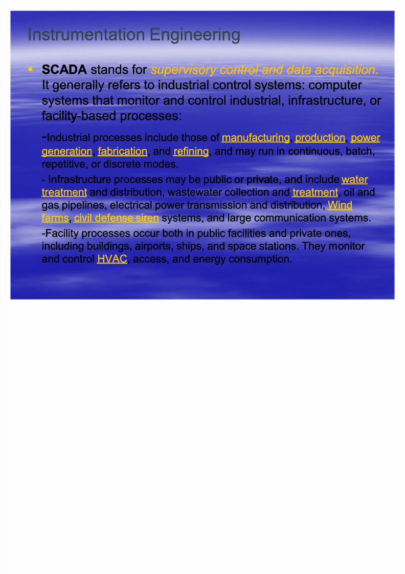
SCADASCADA stands for stands for supervisory cont rol and d at a acquisi t ionsupervisory cont rol and d at a acquisi t ion..It generally refers to industrial control systems: computer It generally refers to industrial control systems: computer
systems that monitor and control industrial, infrastructure, or systems that monitor and control industrial, infrastructure, or
facilityfacility--based processes:based processes:
--Industrial processes include those of Industrial processes include those of manufacturingmanufacturing,, productionproduction,, power power generationgeneration,, fabricationfabrication, and, and refiningrefining, and may run in continuous, batch,, and may run in continuous, batch,
repetitive, or discrete modes.repetitive, or discrete modes.
-- Infrastructure processes may be public or private, and includeInfrastructure processes may be public or private, and include water water
treatmenttreatment and distribution, wastewater collection andand distribution, wastewater collection and treatmenttreatment, oil and, oil and
gas pipelines, electrical power transmission and distribution,gas pipelines, electrical power transmission and distribution, WindWind
farmsfarms,, civilcivil defensedefense sirensiren systems, and large communication systems.systems, and large communication systems.
--Facility processes occur both in public facilities and private ones,Facility processes occur both in public facilities and private ones,
including buildings, airports, ships, and space stations. They monitor including buildings, airports, ships, and space stations. They monitor
and controland control HV ACHV AC, access, and energy consumption., access, and energy consumption.

8/3/2019 ion & Control Eng'g
http://slidepdf.com/reader/full/ion-control-engg 23/106
SCADA schematic overviewSCADA schematic overview

8/3/2019 ion & Control Eng'g
http://slidepdf.com/reader/full/ion-control-engg 24/106
What is Control Engineering?What is Control Engineering?
engineeringengineering discipline that focuses on thediscipline that focuses on themathemat ical mathemat ical mod eli ng mod eli ng systems of a diversesystems of a diverse
nature, analyzing their dynamic behavior,nature, analyzing their dynamic behavior,
and usingand using cont rol theory cont rol theory to make a controller to make a controller
that will cause the systems to behave in athat will cause the systems to behave in a
desired manner.desired manner.
Control engineering is closely related toControl engineering is closely related to
electrical engineeringelectrical engineering, as electronic circuits, as electronic circuitscan often be easily described using controlcan often be easily described using control
theory techniques.theory techniques.

8/3/2019 ion & Control Eng'g
http://slidepdf.com/reader/full/ion-control-engg 25/106
What is meant by Control?What is meant by Control?
ControlControl ± ± the process in a system in whichthe process in a system in which
one or several input variables influenceone or several input variables influence
other output variables as a result of the lawsother output variables as a result of the lawspertaining to the system. Controlling ispertaining to the system. Controlling is
characterized by thecharacterized by the openopen--looploop sequence of sequence of
actions via the single transfer element or theactions via the single transfer element or the
control chain.control chain. (accor d i ng t o DIN 19226)(accor d i ng t o DIN 19226)

8/3/2019 ion & Control Eng'g
http://slidepdf.com/reader/full/ion-control-engg 26/106
As shown in the As shown in the Fig.1Fig.1, the input variables, the input variables xe xe «..acting on«..acting on
this system are linked in a self this system are linked in a self-- contained box andcontained box and
issued as output variablesissued as output variables xa xa«.. and these variables«.. and these variables
now act on the energy flow or mass flow to be controlled.now act on the energy flow or mass flow to be controlled.Fig 1.1Fig 1.1
x x e1e1
x x e2e2 x x a1a1
x x e3e3 x x a2a2
In general:In general: xaxa = f (= f ( xexe ))
The term ³control´ is often applied to the complete systemThe term ³control´ is often applied to the complete systemin which controlling takes place, not only to the controlin which controlling takes place, not only to the control
operation itself.operation itself.

8/3/2019 ion & Control Eng'g
http://slidepdf.com/reader/full/ion-control-engg 27/106
What is meant by Control?What is meant by Control?
The field of control withinThe field of control within chemicalchemical
engineeringengineering is often known asis often known as processprocess
controlcontrol. It deals primarily with the control of . It deals primarily with the control of variables in a chemical process in a plant. Itvariables in a chemical process in a plant. It
employs many of the principles in controlemploys many of the principles in control
engineering, and is a wellengineering, and is a well--established fieldestablished field
in its own right.in its own right.
8/3/2019 ion & Control Eng'g
http://slidepdf.com/reader/full/ion-control-engg 28/106
Process ControlProcess Control (process control(process control
engineering):engineering):
an engineering discipline that deals withan engineering discipline that deals with
architecture, mechanisms, and algorithmsarchitecture, mechanisms, and algorithms
for controlling the output of a specificfor controlling the output of a specificprocess.process.
uses analog sensors to monitor realuses analog sensors to monitor real--worldworld
signals and digital computers to do thesignals and digital computers to do theanalysis and controlling; makes extensiveanalysis and controlling; makes extensive
use of analog/digital and digital/analoguse of analog/digital and digital/analog
conversion.conversion.
8/3/2019 ion & Control Eng'g
http://slidepdf.com/reader/full/ion-control-engg 29/106
In practice, process control systems can beIn practice, process control systems can be
characterized as one or more of the following forms:characterized as one or more of the following forms:
Discr eteDiscr ete ± ± Found in many manufacturing,Found in many manufacturing,
motion and packaging applications, discretemotion and packaging applications, discrete
process control systems use a device calledprocess control systems use a device calledaa progr ammable l ogic cont roller progr ammable l ogic cont roller (PLC) to(PLC) to
read a set of digital and analog inputs, applyread a set of digital and analog inputs, apply
a set of logic statements, and generate a seta set of logic statements, and generate a set
of outputs. Robotic assembly, such as thatof outputs. Robotic assembly, such as thatfound in automotive production, can also befound in automotive production, can also be
characterized as discrete process control.characterized as discrete process control.
8/3/2019 ion & Control Eng'g
http://slidepdf.com/reader/full/ion-control-engg 30/106
In practice, process control systems can beIn practice, process control systems can be
characterized as one or more of the following forms:characterized as one or more of the following forms:
Bat chBat ch ± ± Some applications require thatSome applications require that
specific quantities of raw materials bespecific quantities of raw materials be
combined in specific ways for particular combined in specific ways for particular duration to produce an intermediate or endduration to produce an intermediate or end
result. One example is the production of result. One example is the production of
adhesives and glues, which normally requireadhesives and glues, which normally require
the mixing of raw materials in a heatedthe mixing of raw materials in a heatedvessel for a period of time to form a quantityvessel for a period of time to form a quantity
of end product.of end product.
8/3/2019 ion & Control Eng'g
http://slidepdf.com/reader/full/ion-control-engg 31/106
In practice, process control systems can beIn practice, process control systems can be
characterized as one or more of the following forms:characterized as one or more of the following forms:
C ont inuousC ont inuous ± ± Often, a physical system isOften, a physical system is
represented though variables that arerepresented though variables that are
smooth and uninterrupted in time. Thesmooth and uninterrupted in time. Thecontrol of the water temperature in a heatingcontrol of the water temperature in a heating
jacket, for example, is an example of jacket, for example, is an example of
continuous process control.continuous process control.
Hy brid Hy brid -- applications having elements of applications having elements of
discrete, batch and continuous processdiscrete, batch and continuous process
controlcontrol

8/3/2019 ion & Control Eng'g
http://slidepdf.com/reader/full/ion-control-engg 32/106
W hat is a C ont rol S y stem? W hat is a C ont rol S y stem?
a device or set of devices that manage thea device or set of devices that manage thebehavior of other devices.behavior of other devices.
an interconnection of componentsan interconnection of components(mechanical, electrical, optical, thermal or (mechanical, electrical, optical, thermal or
hydraulic) connected or related in such ahydraulic) connected or related in such a
manner as to command, direct, or regulatemanner as to command, direct, or regulate
itself or another system to maintain aitself or another system to maintain a
desired output.desired output.

8/3/2019 ion & Control Eng'g
http://slidepdf.com/reader/full/ion-control-engg 33/106
W hat is a Cont roller?W hat is a Cont roller?
aa com ponent com ponent of aof a syst emsyst em that makesthat makes i t i t
operate within desired limits.operate within desired limits.
a device that attempts to control thea device that attempts to control the st at esst at esor or out put sout put s of aof a d y namic syst emd y namic syst em. Generally, it. Generally, it
accomplishes this usingaccomplishes this using f eedback f eedback to correctto correct
disturbances to the system; known asdisturbances to the system; known as
c l osed c l osed- - l oo pl oo p controlcontrol..
8/3/2019 ion & Control Eng'g
http://slidepdf.com/reader/full/ion-control-engg 34/106
Example 1.1:Example 1.1:If the output of an air compressor is controlled by the quantityIf the output of an air compressor is controlled by the quantity
drawn in, then:drawn in, then: The opening and closing of the valve is theThe opening and closing of the valve is the cont rol operat ioncont rol operat ion
The valve, whose setting affects the quantity drawn in, is theThe valve, whose setting affects the quantity drawn in, is thecont rol element cont rol element
The opening provided by the valve is theThe opening provided by the valve is the cont rolled variablecont rolled variabley.y.
TheThe handwheelhandwheel with which the valve is actuated is thewith which the valve is actuated is thecont rol d evicecont rol d evice..
The varying load on the compressed air system caused byThe varying load on the compressed air system caused by
the users that affects the control system is thethe users that affects the control system is the d ist ur banced ist ur bancez z . This also applies to speed fluctuations or variations in the. This also applies to speed fluctuations or variations in thedegree of efficiency caused by the compressor. On thedegree of efficiency caused by the compressor. On theaccount of the open action loop of the control system, it isaccount of the open action loop of the control system, it isnot possible to compensate for such disturbance variablnot possible to compensate for such disturbance variables.es.
8/3/2019 ion & Control Eng'g
http://slidepdf.com/reader/full/ion-control-engg 35/106
Types of control loops:Types of control loops:
openopen--loop loop controller controller does not usedoes not use feedbackfeedback toto
controlcontrol statesstates or or outputsoutputs of aof a dynamic systemdynamic system. Open. Open--
loop control is used for systems that are sufficientlyloop control is used for systems that are sufficiently
well characterized to predict whatwell characterized to predict what inputsinputs areare
necessary to achieve the desired states or outputs.necessary to achieve the desired states or outputs.
E.g. the velocity of aE.g. the velocity of a motor motor may be well characterizedmay be well characterized
for thefor the voltagevoltage fed into it, in which case feedback mayfed into it, in which case feedback may
not be necessary.not be necessary.
closedclosed--loop loop controller controller usesuses feedbackfeedback to controlto control
statesstates or or outputsoutputs of aof a dynamic systemdynamic system..

8/3/2019 ion & Control Eng'g
http://slidepdf.com/reader/full/ion-control-engg 36/106
Fig. 1.2 shows the block diagram representing an openFig. 1.2 shows the block diagram representing an open--
loop control itself together with the system to be controlled.loop control itself together with the system to be controlled.
Fig. 1.2Fig. 1.2
DisturbanceDisturbance z1z1
Energy/MassEnergy/Mass
FlowFlow
Controller OutputController Output
yy Sequence of ActionsSequence of Actions
( Action Loop)( Action Loop)
DisturbanceDisturbance z2z2
Controlled
System
Controller

8/3/2019 ion & Control Eng'g
http://slidepdf.com/reader/full/ion-control-engg 37/106
Controller
Sequence
of Actions
Controlled System
Controller Output
(Error) y
Energy/
Mass Flow
Command Variable w
Disturbance z2
Disturbance z1 Controlled
Variable x
Controller
Fig. 1.3 Closed-Loop Controller

8/3/2019 ion & Control Eng'g
http://slidepdf.com/reader/full/ion-control-engg 38/106
AutomaticAutomatic controlcontrol
ProcessProcess inin whichwhich thethe cont rolled cont rolled variablevariable isiscontinuouslycontinuously measuredmeasured andand comparedcompared withwith another another variable,variable, thethe command command variable,variable, thethe processprocess beingbeinginfluencedinfluenced accordingaccording toto thethe resultresult of of thisthis comparisoncomparisonbyby modifyingmodifying toto matchmatch thethe command command variablevariable..
TheThe sequencesequence of of actionsactions resultingresulting fromfrom thisthis takestakesplaceplace inin aa closedclosed loop,loop, thethe cont rol cont rol looploop.. TheThe purposepurposeof of thethe closed closed looploop controlcontrol isis toto matchmatch thethe valuevalue of of thethecontrolledcontrolled variablevariable toto thethe valuevalue specifiedspecified byby thethe
commandcommand variablevariable eveneven if if perfectperfect equalizationequalization isis notnotattainedattained under under thethe prevailingprevailing circumstancescircumstances.. (according(accordingtoto DINDIN 1922619226))

8/3/2019 ion & Control Eng'g
http://slidepdf.com/reader/full/ion-control-engg 39/106
Terms and Definitions:Terms and Definitions: Controlled SystemControlled System ± ± the part of the total system to bethe part of the total system to be
influenced.influenced.
Actuator Actuator ± ± element that acts on the mass flow or energyelement that acts on the mass flow or energy
flow to be controlled and is located at the input to theflow to be controlled and is located at the input to the
controlled system.controlled system.
Actuating pathActuating path ± ± path along which the actions determiningpath along which the actions determininga control operation are transmitted.a control operation are transmitted.
Controller Controller ± ± part of the actuating path causing thepart of the actuating path causing the
controlled system to be influenced by the actuator; thecontrolled system to be influenced by the actuator; the
control or automatic control proper whose elements link thecontrol or automatic control proper whose elements link theinput signals in accordance with the respective laws.input signals in accordance with the respective laws.
Disturbance pointDisturbance point -- point at which a factor acts that is notpoint at which a factor acts that is not
influenced by the system and which disturbs the conditioninfluenced by the system and which disturbs the condition
to be maintained.to be maintained.

8/3/2019 ion & Control Eng'g
http://slidepdf.com/reader/full/ion-control-engg 40/106
Variables and their ranges in the actuatingVariables and their ranges in the actuating
path:path:
Controller outputController output y y ± ± output from the controller andoutput from the controller and
at the same time input variable to the controlat the same time input variable to the control
system.system.
Controller output rangeController output range y y hh ± ± range within which therange within which theoutput maybe adjusted.output maybe adjusted.
Desired valueDesired value x x A A ± ± value to be acted upon by thevalue to be acted upon by the
controlcontrol
Control rangeControl range x x Ah Ah ± ± range within which the desiredrange within which the desiredvalue may be when the control is operatedvalue may be when the control is operated
properly.properly.

8/3/2019 ion & Control Eng'g
http://slidepdf.com/reader/full/ion-control-engg 41/106
Variables and their ranges in the actuatingVariables and their ranges in the actuating
path:path:
Command variableCommand variable w w ± ± value introduced from thevalue introduced from theoutside to the control chain or to the control loopoutside to the control chain or to the control loop
whose output value is to follow in a predeterminedwhose output value is to follow in a predetermined
manner (manner (ieie.. setpointsetpoint device in close loop control,device in close loop control,
input signal in open loop control.)input signal in open loop control.)w w hh ± ± range of command variablerange of command variable
Disturbance variableDisturbance variable z z ± ± variable acting from thevariable acting from the
outside that influences the intended action of theoutside that influences the intended action of the
control.control.
z z hh ± ± range within which the disturbance variable mayrange within which the disturbance variable may
be allowed without adversely affecting thebe allowed without adversely affecting the
operability of the control.operability of the control.
8/3/2019 ion & Control Eng'g
http://slidepdf.com/reader/full/ion-control-engg 42/106
Example 2: House heating/ Air Example 2: House heating/ Air--conditioning systemconditioning system
In this example:In this example:
TheThe ther
most at ther
most at acts as theacts as the cont roller cont roller which directswhich directsthe activities of the heater.the activities of the heater.
heater or the air heater or the air--conditioner is the processor thatconditioner is the processor that
warms or cools the air inside the house.warms or cools the air inside the house.
thethe air air comi ng comi ng into the heater or air into the heater or air--conditioner is theconditioner is thei n put i n put ..
thethe air g oi ng out air g oi ng out of the heater of the heater or air conditioner is itsor air conditioner is its
out put out put ..
thethe air air t em perat ure read i ng st em perat ure read i ng s inside the house are theinside the house are the
f eedback f eedback s.s.
and finally, theand finally, the househouse is theis the environment environment in which thein which the
heating/air heating/air--conditioning system operatesconditioning system operates

8/3/2019 ion & Control Eng'g
http://slidepdf.com/reader/full/ion-control-engg 43/106
W hat is feed back ? W hat is feed back ?
In cybernetics and control theory, feedback isIn cybernetics and control theory, feedback isa process whereby some proportion or ina process whereby some proportion or in
general, function, of the output signal of ageneral, function, of the output signal of a
system is passed (fed back) to the input.system is passed (fed back) to the input.
Often this is done intentionally, in order toOften this is done intentionally, in order to
control the dynamic behavior of the system.control the dynamic behavior of the system.
Feedback may be:Feedback may be:
neg at iveneg at ive, which tends to reduce output, or , which tends to reduce output, or
posi t ive posi t ive, which tends to increase output., which tends to increase output.

8/3/2019 ion & Control Eng'g
http://slidepdf.com/reader/full/ion-control-engg 44/106
Example 3Example 3P rocess:P rocess: cooling a roomcooling a room
Desired out come:Desired out come: reach/ maintain a definedreach/ maintain a definedtemperature constant over temperature constant over
time, say 20time, say 20 oo CC
Cont rolled variableCont rolled variable:: temperaturetemperature
I n put variable:I n put variable: temperature, since it is measuredtemperature, since it is measured
by a thermometer and is used toby a thermometer and is used to
decide whether to cool or notdecide whether to cool or not
Set poi nt Set poi nt :: 2020oo
CCManipulat ed variable:Manipulat ed variable: state of the cooler (the settingstate of the cooler (the setting
of the valve allowing chilled water to flow throughof the valve allowing chilled water to flow through
it)it)

8/3/2019 ion & Control Eng'g
http://slidepdf.com/reader/full/ion-control-engg 45/106
SignalsSignals
Signals represent information, theSignals represent information, the
representation may refer to the value or therepresentation may refer to the value or the
change in values of a physical dimensionchange in values of a physical dimension
and may refer to transmission, processing or and may refer to transmission, processing or
storage of information.storage of information.
In abstract considerations, signal refers toIn abstract considerations, signal refers to
values or change in value of mathematicalvalues or change in value of mathematicalquantities.quantities.

8/3/2019 ion & Control Eng'g
http://slidepdf.com/reader/full/ion-control-engg 46/106
Types of SignalsTypes of Signals
Analog Analog ± ± information is assigned continuouslyinformation is assigned continuously
point by point to a range of values.point by point to a range of values.
DigitalDigital ± ± the range to be considered is dividedthe range to be considered is divided
into a finite number of separate value ranges,into a finite number of separate value ranges,
and one specific item of information is assignedand one specific item of information is assigned
to each range of values.to each range of values.
The digital group includes theThe digital group includes the binary signalbinary signal,,also known as analso known as an onon--off signaloff signal, representing, representing
two items of information.two items of information.

8/3/2019 ion & Control Eng'g
http://slidepdf.com/reader/full/ion-control-engg 47/106
Types of SignalsTypes of Signals
Digital signals are used more frequently inDigital signals are used more frequently incontrol engineering and the digital signals arecontrol engineering and the digital signals are
mainly in the form of binary signals.mainly in the form of binary signals.
These binary signals are of considerableThese binary signals are of considerablesignificance for information processing becausesignificance for information processing because
they can easily be produced by equipment (e.g.they can easily be produced by equipment (e.g.
switches) and can also be processed simply.switches) and can also be processed simply.
In practice, it is essential to clearly define theIn practice, it is essential to clearly define the
relationship between range of values and signalrelationship between range of values and signal
in the case of binary signalsin the case of binary signals

8/3/2019 ion & Control Eng'g
http://slidepdf.com/reader/full/ion-control-engg 48/106
Analog Analog/Digital Signals illustrated/Digital Signals illustrated
If a continuously changeable pressure from 0If a continuously changeable pressure from 0
to 600kPa is considered, each intermediateto 600kPa is considered, each intermediate
value of the range maybe assigned a specificvalue of the range maybe assigned a specific
signal.signal. If the pressure is indicated on a BourdonIf the pressure is indicated on a Bourdon
pressure gauge, each intermediate valuepressure gauge, each intermediate value
corresponds to a specific position of thecorresponds to a specific position of thepointer. The position of the pointer representspointer. The position of the pointer represents
anan analoganalog signal.signal.

8/3/2019 ion & Control Eng'g
http://slidepdf.com/reader/full/ion-control-engg 49/106
Analog Analog/Digital Signals illustrated/Digital Signals illustrated
If the dial is now divided into separate valueIf the dial is now divided into separate valueranges, say in pressure steps of 50ranges, say in pressure steps of 50 kPakPa andand
if each range is assigned a specific item of if each range is assigned a specific item of
information:information:
50 . . .50 . . . 100100 kPakPa,, value =1value =1100 . . .100 . . . 150150 kPakPa,, value = 1.5value = 1.5
150 . . .150 . . . 200kPa,200kPa, value =2,value =2,
Then, we are dealing with digitalThen, we are dealing with digitalsignals!signals!

8/3/2019 ion & Control Eng'g
http://slidepdf.com/reader/full/ion-control-engg 50/106
Signal Flow DiagramSignal Flow Diagram
The Symbolic representation of theThe Symbolic representation of theeffective relationships between the signalseffective relationships between the signals
in a system.in a system. Block and line of actionBlock and line of action
XXe1e1
Linkage pointsLinkage points xxa1a1
XXe2e2
Branch pointsBranch points
X
X
X
X

8/3/2019 ion & Control Eng'g
http://slidepdf.com/reader/full/ion-control-engg 51/106
Representation of a closed loop in the signal flow diagram
Xe1
Xe2 = y
y
X
W
Xd = W - X
_
+

8/3/2019 ion & Control Eng'g
http://slidepdf.com/reader/full/ion-control-engg 52/106
Breakdown of the Control ChainBreakdown of the Control Chain
In the preceding sections, the controller hasIn the preceding sections, the controller hasbeen represented as a self been represented as a self--contained blockcontained block
which can be broken down even further. A which can be broken down even further. A
control can always be broken down by thecontrol can always be broken down by the
same method to show the arrangement of thesame method to show the arrangement of theindividual components; at the same timeindividual components; at the same time
showing the signal flow.showing the signal flow.
The control chain is thus characterized by aThe control chain is thus characterized by asignal flow from signal input via signalsignal flow from signal input via signal
processing to signal output/execution of processing to signal output/execution of
instruction.instruction.

8/3/2019 ion & Control Eng'g
http://slidepdf.com/reader/full/ion-control-engg 53/106
Breakdown of the control chain:
Actuating Device
Processing Element
Input Element
Signal output/ execution
of instruction
Signal Processing
Signal input
Hardware breakdown Signal Flow
H d tH d t

8/3/2019 ion & Control Eng'g
http://slidepdf.com/reader/full/ion-control-engg 54/106
Hardware terms:Hardware terms:
Actuating mechanism
Actuating mechanism ± ± element that has direct effect on aelement that has direct effect on acontrolled system, moves the final control element whencontrolled system, moves the final control element when
mechanically actuated.mechanically actuated.
Actuating device Actuating device ± ± consists of actuating mechanism and finalconsists of actuating mechanism and final
control element.control element.
Signal transducer Signal transducer ± ± device transform an input signal as clearlydevice transform an input signal as clearly
as possible into an associated output signal, where necessaryas possible into an associated output signal, where necessary
using auxiliary energy. Among others, this group of devicesusing auxiliary energy. Among others, this group of devices
includes amplifiers and signal converters.includes amplifiers and signal converters.
Signal amplifier Signal amplifier ± ± device using auxiliary energy for power device using auxiliary energy for power amplification.amplification.
Signal Converter Signal Converter ± ± devices in which input and output signalsdevices in which input and output signals
have different structurehave different structure
Examples of Hardware ElementsExamples of Hardware Elements

8/3/2019 ion & Control Eng'g
http://slidepdf.com/reader/full/ion-control-engg 55/106
Examples of Hardware ElementsExamples of Hardware Elements Signal elements:Signal elements: limit switch with cam and roller limit switch with cam and roller
operation, proximity switches,operation, proximity switches,light barriers, reflex sensors,light barriers, reflex sensors,
push buttons, manual switches,push buttons, manual switches,
etc.etc.
Processing elements:Processing elements: Electronic logic elements,Electronic logic elements,contactors, relays, valvescontactors, relays, valves
released by pneumatic logic, etc.released by pneumatic logic, etc.
Final control elements:Final control elements: Power contactors, pneumaticPower contactors, pneumatic
and hydraulic (directional control)and hydraulic (directional control)valves, etc.valves, etc.
Drive elements:Drive elements: Electric motors, pneumatic/Electric motors, pneumatic/
hydraulic motors, cylinders, etc.hydraulic motors, cylinders, etc.

8/3/2019 ion & Control Eng'g
http://slidepdf.com/reader/full/ion-control-engg 56/106
Types of controlsTypes of controls visvis aa visvis power requirement:power requirement:
Control without auxiliaryControl without auxiliary ± ± power requirement topower requirement to
adjust the final control element is provided by theadjust the final control element is provided by theinput element of the control.input element of the control.
Control with auxiliary energyControl with auxiliary energy ± ± power required topower required to
adjust the final control element is supplied entirely or adjust the final control element is supplied entirely or
in part through a source of auxiliary energy.in part through a source of auxiliary energy.
It is possible to operate with different levels of It is possible to operate with different levels of
energy within the control chain, thus it is necessaryenergy within the control chain, thus it is necessary
to distinguish theto distinguish the working energyworking energy ± ± the energythe energyrequired to operate the actuating device, from therequired to operate the actuating device, from the
control energycontrol energy that supplies the signal input andthat supplies the signal input and
signal processing.signal processing.
8/3/2019 ion & Control Eng'g
http://slidepdf.com/reader/full/ion-control-engg 57/106
Based on these considerations, an extended controlBased on these considerations, an extended control
chain can be drawn up as follows:chain can be drawn up as follows:
Input Element
Processing element
Transducer
Actuating
Device
Controlled System
Execution of
Instruction
Signal Output
Processing element
Signal element
Controller
Operative part
Examples of hardware used for Electrical and Pneumatic Systems

8/3/2019 ion & Control Eng'g
http://slidepdf.com/reader/full/ion-control-engg 58/106
Actuating Mechanism
Final Control Elements
Electric Motor
Solenoid
Linear motor
Power contactors
Pneumatic cylinder
Air motor
Directional control valves
Processing Elements Auxiliary Contactors
Relays
Directional control valves
Non-return valves
Pressure control valves
Flow Control valves
Input Elements Switches
Push buttons
Limit switches
Program generators
Proximity signallers
Switches
Push buttons
Limit switches
Program generators
Proximity signallers
Electrical Systems Pneumatic Systems
Examples of hardware used for Electrical and Pneumatic Systems
Ex Control with the same form of energy for theEx Control with the same form of energy for the
8/3/2019 ion & Control Eng'g
http://slidepdf.com/reader/full/ion-control-engg 59/106
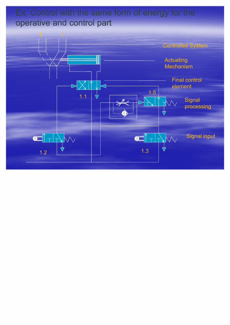
Ex. Control with the same form of energy for theEx. Control with the same form of energy for the
operative and control partoperative and control part
II I
Controlled System
Actuating
Mechanism
Final controlelement
Signal
processing
Signal input
1.31.2
1.51.1

8/3/2019 ion & Control Eng'g
http://slidepdf.com/reader/full/ion-control-engg 60/106
Types of energy for operative and control partTypes of energy for operative and control part
By means of suitable devices (signal transformers/By means of suitable devices (signal transformers/
transducers) it is possible to convert one type of transducers) it is possible to convert one type of energy into signals of another type of energyenergy into signals of another type of energy ± ± inin
control engineering, one can work within the controlledcontrol engineering, one can work within the controlled
system with different types of energy.system with different types of energy.
In practice however, it is not always easy to select theIn practice however, it is not always easy to select the
³right control system´. Apart from the immediate³right control system´. Apart from the immediate
requirements of the problem, therequirements of the problem, the auxiliaryauxiliary
requirementsrequirements in particular (place of installation,in particular (place of installation,
environmental influences, etc.) determine the solution.environmental influences, etc.) determine the solution.
These auxiliary often conflict with the simple solutionThese auxiliary often conflict with the simple solution
to the problem that can make project engineeringto the problem that can make project engineering
more difficult.more difficult.

8/3/2019 ion & Control Eng'g
http://slidepdf.com/reader/full/ion-control-engg 61/106
Types of energy for operative and control partTypes of energy for operative and control part
If a system uses different types of energy for theIf a system uses different types of energy for the
operative and control parts, one refers to aoperative and control parts, one refers to a mixedmixedtechnologytechnology ± ± which is being used to an increasingwhich is being used to an increasing
extent in control design.extent in control design.
Working Media:-Mechanical
-Electrical
-Hydraulics
-Pneumatics
Criteria for system selection:-Force
-Displacement
-Type of motion
-Speed-Physical size
-Life
-Sensitivity
-Working safety
Ch i i f ki diCh i i f ki di

8/3/2019 ion & Control Eng'g
http://slidepdf.com/reader/full/ion-control-engg 62/106
Characteristics of working media:Characteristics of working media:
Electrical:Electrical:
Energy storage difficult, transmission fast, costs low.Energy storage difficult, transmission fast, costs low.Creation of straight line motion complex andCreation of straight line motion complex and
expensive, as it is necessary either to convert byexpensive, as it is necessary either to convert by
mechanical means or short displacements possiblemechanical means or short displacements possible
with lifting magnets and only small forces possiblewith lifting magnets and only small forces possiblewith linear motors.with linear motors.
Creation of rotary motion at very high efficiency,Creation of rotary motion at very high efficiency,
large physical size, speed limited, speed torquelarge physical size, speed limited, speed torque
regulation difficult and elaborateregulation difficult and elaborate
Elements not overloadElements not overload--proof, not intrinsicallyproof, not intrinsically
explosionexplosion--proof.proof.
Characteristics of working media:Characteristics of working media:

8/3/2019 ion & Control Eng'g
http://slidepdf.com/reader/full/ion-control-engg 63/106
Characteristics of working media:Characteristics of working media:
HydraulicsHydraulics
Storage of energy only to a limited degree, limitedStorage of energy only to a limited degree, limitedand slow energy transmission, high energy cost.and slow energy transmission, high energy cost.
Creation of straight line motion is very simple,Creation of straight line motion is very simple,
working speed not too high (up to 0.5m/s max.), veryworking speed not too high (up to 0.5m/s max.), very
small dimensions, large to very large forces can besmall dimensions, large to very large forces can beachieved.achieved.
Creation of rotary motion is simple, however at notCreation of rotary motion is simple, however at not
very high speed, speeds constant even at lowvery high speed, speeds constant even at low
range, high efficiency, high torquerange, high efficiency, high torque
Elements are overloadElements are overload--proof, line installation difficultproof, line installation difficult
and expensive and must be insured that system isand expensive and must be insured that system is
completely sealed.completely sealed.
8/3/2019 ion & Control Eng'g
http://slidepdf.com/reader/full/ion-control-engg 64/106
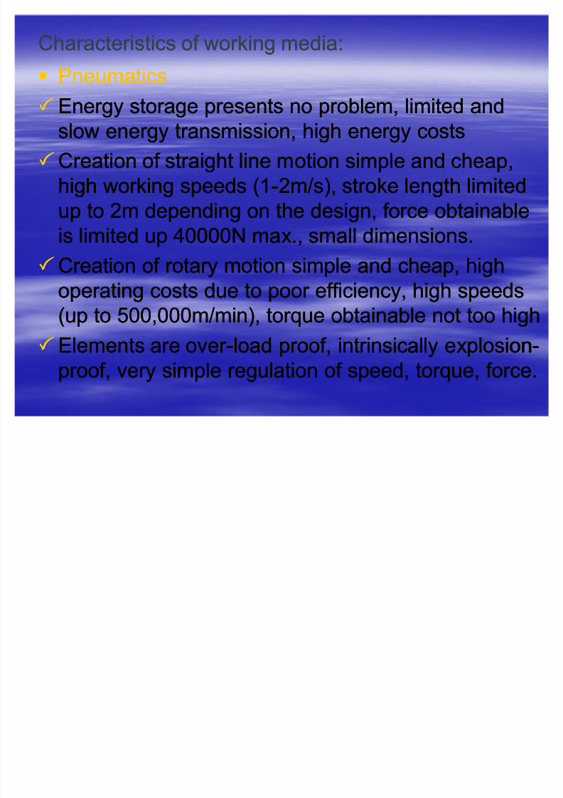
Characteristics of working media:Characteristics of working media:
PneumaticsPneumatics
Energy storage presents no problem, limited andEnergy storage presents no problem, limited andslow energy transmission, high energy costsslow energy transmission, high energy costs
Creation of straight line motion simple and cheap,Creation of straight line motion simple and cheap,
high working speeds (1high working speeds (1--2m/s), stroke length limited2m/s), stroke length limited
up to 2m depending on the design, force obtainableup to 2m depending on the design, force obtainableis limited up 40000N max., small dimensions.is limited up 40000N max., small dimensions.
Creation of rotary motion simple and cheap, highCreation of rotary motion simple and cheap, high
operating costs due to poor efficiency, high speedsoperating costs due to poor efficiency, high speeds
(up to 500,000m/min), torque obtainable not too high(up to 500,000m/min), torque obtainable not too high
Elements are over Elements are over--load proof, intrinsically explosionload proof, intrinsically explosion--
proof, very simple regulation of speed, torque, force.proof, very simple regulation of speed, torque, force.

8/3/2019 ion & Control Eng'g
http://slidepdf.com/reader/full/ion-control-engg 65/106
Types of energy for operative and control partTypes of energy for operative and control part
Control Media:Control Media: Criteria for system selection:Criteria for system selection:
-- MechanicalMechanical -- Signal speedSignal speed
-- ElectricalElectrical -- Switching times of Switching times of elementselements
-- ElectronicsElectronics -- Working safety of elementsWorking safety of elements
-- Low pressure pneumaticsLow pressure pneumatics -- LifeLife
-- Normal pressure pneumaticsNormal pressure pneumatics -- Sensitivity to environmentalSensitivity to environmental
influencesinfluences
-- HydraulicsHydraulics -- Space requirementSpace requirement
-- Ease of maintenanceEase of maintenance

8/3/2019 ion & Control Eng'g
http://slidepdf.com/reader/full/ion-control-engg 66/106
Electrical Electronics Normal-pressure
pneumatics
Low-pressure
pneumaticsSignal speed Very high,
approx speed of
sound
Very high,
approx speed of
sound
Approx 40-70 m/s 100-200m/s
normal, to some
extent speed of
light
Distance w/c can
be covered
Practically
unlimited
Practically
unlimited
Limited by speed of
signal
Limited by speed of
signalSwitching times
of elements
Greater than 10
ms
Less than 1 ms Greater than 10 ms Greater than 10 ms
Reliability Sensitive to envi
influences
Very sensitive to
envi influences
Insensitive to envi
influences
Insensitive to envi
influences
Space
requirement
large Very small Very large small
Main type of
signal processing
digital Digital, analog digital Digital, analog
Components Contactors,
relays
Electronic
valves,
transistors
Directional control
valves
Static, dynamic
elements
Characteristics of Control media:
Diff ti ti h t i ti f t lDiff ti ti h t i ti f t l

8/3/2019 ion & Control Eng'g
http://slidepdf.com/reader/full/ion-control-engg 67/106
Differentiating characteristics of controlsDifferentiating characteristics of controls
Controls can be classified according to:Controls can be classified according to: Control energy usedControl energy used
Mode of operation with respect to signal processingMode of operation with respect to signal processing
Combined controlsCombined controls ± ± a certain combination of a certain combination of input signals is always associated with ainput signals is always associated with a
combination of combination of output signals. These signalsoutput signals. These signals
operate without timeoperate without time behavior behavior..
Sequential controlsSequential controls ± ± controls containingcontrols containingelements with timeelements with time behavior behavior (e.g. Timing(e.g. Timing
elements, storage devices, etc.elements, storage devices, etc.
8/3/2019 ion & Control Eng'g
http://slidepdf.com/reader/full/ion-control-engg 68/106
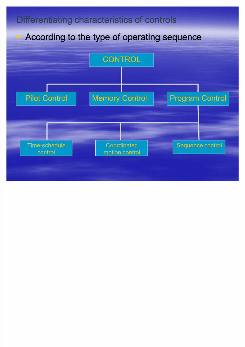
Differentiating characteristics of controlsDifferentiating characteristics of controls
According to the type of operating sequence According to the type of operating sequence
CONTROL
Pilot Control Memory Control Program Control
Time-schedule
control
Coordinated
motion control
Sequence control

8/3/2019 ion & Control Eng'g
http://slidepdf.com/reader/full/ion-control-engg 69/106
Differentiating characteristics of controlsDifferentiating characteristics of controls
Pilot ControlPilot Control ± ± establishes always a uniqueestablishes always a unique
relationship between the command variablerelationship between the command variable
and output variable.and output variable.
Examples:Examples:
1.1. Copying on machine toolsCopying on machine tools ± ± the movements of the movements of the tracer pin are uniquely related to thethe tracer pin are uniquely related to the
movement of the cutting toolmovement of the cutting tool
2.2. Brightness controlBrightness control ± ± the brightness of the lamp isthe brightness of the lamp is
at all times uniquely related to the position of theat all times uniquely related to the position of the
resistor or of the transformer.resistor or of the transformer.

8/3/2019 ion & Control Eng'g
http://slidepdf.com/reader/full/ion-control-engg 70/106
Differentiating characteristics of controlsDifferentiating characteristics of controls
Memory controlMemory control ± ± after removing or taking back theafter removing or taking back the
command variable, the value reached by the outputcommand variable, the value reached by the outputvariable is retained until an opposing signal isvariable is retained until an opposing signal is
presented.presented.
Example:Example: SwitchSwitch--on and switch off of an electric motor on and switch off of an electric motor
by means of a pressure switchby means of a pressure switchRo
³ OFF´ b2
³ON´ b1
c1
Mp
3 ± 380 V
RST
M

8/3/2019 ion & Control Eng'g
http://slidepdf.com/reader/full/ion-control-engg 71/106
1.31.2
1.1
Example: Controlling the advance and return movement of a double-
acting cylinder by manual switch.
Here, the condition obtained by the output variable is retained after the
command variable has been removed, until the opposing signal ispresented.
Diff ti ti h t i ti f t lDiff ti ti h t i ti f t l

8/3/2019 ion & Control Eng'g
http://slidepdf.com/reader/full/ion-control-engg 72/106
Differentiating characteristics of controlsDifferentiating characteristics of controls
TimeTime--schedule controlschedule control
Command variables are supplied by a timeCommand variables are supplied by a time--dependentdependentprogram transmitter (program storage device) and aprogram transmitter (program storage device) and a
timetime--dependent operating sequence of the program.dependent operating sequence of the program.
Centrally stored program; usually compactCentrally stored program; usually compact
constructionconstruction
TimeTime--constant program execution; executionconstant program execution; execution
insensitive to disturbing factors and independent/noinsensitive to disturbing factors and independent/no
check of operating sequence, hence no sequencecheck of operating sequence, hence no sequencereliability. Disturbances in the operating sequencereliability. Disturbances in the operating sequence
have no effect on program execution.have no effect on program execution.
Differentiating characteristics of controlsDifferentiating characteristics of controls

8/3/2019 ion & Control Eng'g
http://slidepdf.com/reader/full/ion-control-engg 73/106
Differentiating characteristics of controlsDifferentiating characteristics of controls
Coordinated motion controlCoordinated motion control
The command variables are provided by a programThe command variables are provided by a programtransmitter, the output variables of w/c aretransmitter, the output variables of w/c are
dependent on the distance covered (displacement or dependent on the distance covered (displacement or
position of a movable part of the controlled system.position of a movable part of the controlled system.
Program is defined by the arrangement of limitProgram is defined by the arrangement of limitswitches/ signal elements, hence the layout is notswitches/ signal elements, hence the layout is not
clearly arranged and is not easy to serviceclearly arranged and is not easy to service
Operating sequence reliability is provided byOperating sequence reliability is provided by
displacementdisplacement--dependent sequence, disturbances independent sequence, disturbances in
the operating sequence can be registered, programthe operating sequence can be registered, program
execution maybe interruptedexecution maybe interrupted
Diff ti ti h t i ti f t lDiff ti ti h t i ti f t l

8/3/2019 ion & Control Eng'g
http://slidepdf.com/reader/full/ion-control-engg 74/106
Differentiating characteristics of controlsDifferentiating characteristics of controls
A A program transmitter program transmitter maybe:maybe:
-- camshaft, cam disk, program belt, punchcamshaft, cam disk, program belt, punch
card/tape, etc.card/tape, etc.
Example: A piano displays the characteristicsExample: A piano displays the characteristics
of a timeof a time--schedule control. The program isschedule control. The program iscontained in a program transmitter, which incontained in a program transmitter, which in
this case maybe a drum and is run throughthis case maybe a drum and is run through
on a timeon a time--dependent basis (constant speeddependent basis (constant speedof program transmitter drive motor)of program transmitter drive motor)
Example ± Coordinated motion control

8/3/2019 ion & Control Eng'g
http://slidepdf.com/reader/full/ion-control-engg 75/106
Example Coordinated motion control
Movement of a double-acting pneumatic cylinder: The advance motion is
tripped by operating ST ART button 1.2, the return motion being effected by a
limit switch1.3 after a certain length of travel, depending on the position of LS
1.3
1.31.2
1.1
1.3 1.0
Differentiating characteristics of controlsDifferentiating characteristics of controls

8/3/2019 ion & Control Eng'g
http://slidepdf.com/reader/full/ion-control-engg 76/106
Differentiating characteristics of controlsDifferentiating characteristics of controls
Sequence controlSequence control
The operating sequence program is stored in aThe operating sequence program is stored in aprogram transmitter w/c runs through a ³stepprogram transmitter w/c runs through a ³step--byby--
step´ program in accordance w/ the conditionstep´ program in accordance w/ the condition
reached at any one time by the controlled system.reached at any one time by the controlled system.
Is identified by having a program transmitter and anIs identified by having a program transmitter and anequipment w/c is capable of ³interrogating´ theequipment w/c is capable of ³interrogating´ the
conditions prevailing in the system, has theconditions prevailing in the system, has the
advantage of ³check the momentary machineadvantage of ³check the momentary machine
status´ (operating sequence reliability and isstatus´ (operating sequence reliability and ispossible to advance the program transmitter steppossible to advance the program transmitter step--
byby--step (stepping motor).step (stepping motor).
M f ti tiM f ti ti

8/3/2019 ion & Control Eng'g
http://slidepdf.com/reader/full/ion-control-engg 77/106
Means of representing motionMeans of representing motion
sequences and switching conditions:sequences and switching conditions:
Movement sequences and switching conditionsMovement sequences and switching conditions
of working and control elements must beof working and control elements must be
represented in a clear fashion. As we mayberepresented in a clear fashion. As we maybe
confronted with a more difficult problem, theconfronted with a more difficult problem, therelationships can be identified quickly and withrelationships can be identified quickly and with
certainty only if a suitable form of certainty only if a suitable form of
representation can be selected.representation can be selected.Only neat representation allows largeOnly neat representation allows large--scalescale
projects to be understood clearly.projects to be understood clearly.
Means of representing motion sequences andMeans of representing motion sequences and

8/3/2019 ion & Control Eng'g
http://slidepdf.com/reader/full/ion-control-engg 78/106
Means of representing motion sequences andMeans of representing motion sequences and
switching conditions:switching conditions:
Writing down in chronological sequenceWriting down in chronological sequence
Tabular formTabular form
Vector diagramVector diagram
Graphical representation in graphical form,Graphical representation in graphical form,
commonly referred to ascommonly referred to as Function DiagramFunction Diagram,,consisting of:consisting of:
1.1. Motion DiagramMotion Diagram ± ± records conditions relating torecords conditions relating to
working elements and componentsworking elements and components2.2. Control DiagramControl Diagram ± ± provides informationprovides information
concerning the condition of individual controlconcerning the condition of individual control
elementselements

8/3/2019 ion & Control Eng'g
http://slidepdf.com/reader/full/ion-control-engg 79/106
Motion diagrams:Motion diagrams:
DisplacementDisplacement--step diagramstep diagram ± ± The operating sequenceThe operating sequence
of a working element is represented in a manner suchof a working element is represented in a manner suchthat the displacement is recorded in relation to thethat the displacement is recorded in relation to the
various steps or change in condition of anyvarious steps or change in condition of any
component. If a control has several working elements,component. If a control has several working elements,
each is represented in the same manner and each iseach is represented in the same manner and each is
drawn one beneath the other.drawn one beneath the other.
Displacement
Steps
Forward (1)
Rear (0)
1 2 3 4 5=1
Cylinder A
Recommendations for layout when drawingRecommendations for layout when drawing

8/3/2019 ion & Control Eng'g
http://slidepdf.com/reader/full/ion-control-engg 80/106
Recommendations for layout when drawingRecommendations for layout when drawing
displacementdisplacement--step diagram:step diagram:
The steps should be drawn (when possible) linearly andThe steps should be drawn (when possible) linearly andhorizontally.horizontally.
If possible, the displacement should not be drawn to scale, butIf possible, the displacement should not be drawn to scale, but
of equal size for all components.of equal size for all components.
If the condition of the system changes during motion,If the condition of the system changes during motion,intermediate steps maybe introduced.intermediate steps maybe introduced.
The steps may be numbered as required.The steps may be numbered as required.
The designation of the condition may be optional, binary digitsThe designation of the condition may be optional, binary digits
may be used, say 0 for rear end position and 1 for forward endmay be used, say 0 for rear end position and 1 for forward end
position.position.
The designation of the unit must be written on the left side of The designation of the unit must be written on the left side of
the diagram.the diagram.
M ti DiM ti Di
8/3/2019 ion & Control Eng'g
http://slidepdf.com/reader/full/ion-control-engg 81/106
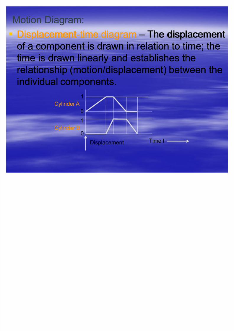
Motion Diagram:Motion Diagram:
DisplacementDisplacement--time diagramtime diagram ± ± The displacementThe displacement
of a component is drawn in relation to time; theof a component is drawn in relation to time; thetime is drawn linearly and establishes thetime is drawn linearly and establishes the
relationship (motion/displacement) between therelationship (motion/displacement) between the
individual components.individual components.
Displacement Time t
0
1
Cylinder A
1
0Cylinder B
Recommendations for layout when drawingRecommendations for layout when drawing

8/3/2019 ion & Control Eng'g
http://slidepdf.com/reader/full/ion-control-engg 82/106
Recommendations for layout when drawingRecommendations for layout when drawing
displacementdisplacement--step diagram:step diagram:
The rules for drawing the diagram are roughly the same asThe rules for drawing the diagram are roughly the same asfor the displacementfor the displacement--step diagram; the relationships to thestep diagram; the relationships to the
displacementdisplacement--step diagram are indicated by the broken linesstep diagram are indicated by the broken lines
(step lines), although the distance between them is not drawn(step lines), although the distance between them is not drawn
to scale.to scale.
Whereas the displaceWhereas the displace--step diagram allows the relationshipsstep diagram allows the relationships
to be seen more clearly, overlaps and varying speeds can beto be seen more clearly, overlaps and varying speeds can be
shown better in the displacementshown better in the displacement--time diagramtime diagram
In case of rotating elements, the changes in condition withIn case of rotating elements, the changes in condition with
respect to time are no longer accounted for, i.e. in therespect to time are no longer accounted for, i.e. in thedisplacementdisplacement--step diagram, a change in condition (e.g.step diagram, a change in condition (e.g.
Switching of an electric motor) does not extend over theSwitching of an electric motor) does not extend over the
whole step but is entered directly on the step linewhole step but is entered directly on the step line
Control DiagramControl Diagram

8/3/2019 ion & Control Eng'g
http://slidepdf.com/reader/full/ion-control-engg 83/106
Control DiagramControl Diagram
In the control diagram, the switching condition of In the control diagram, the switching condition of
control element is shown in relation to the steps or control element is shown in relation to the steps or the times, the switching time itself not beingthe times, the switching time itself not being
considered, for example the condition of a relayconsidered, for example the condition of a relay b1b1
being opened:being opened:
Note that relay b1 pulls up at step 2 and drops off Note that relay b1 pulls up at step 2 and drops off
again at step 5.again at step 5.
Condition
Steps
Open
Closed
b1
1 2 3 4 5 6=1
Function Diagram Example:

8/3/2019 ion & Control Eng'g
http://slidepdf.com/reader/full/ion-control-engg 84/106
Function Diagram, Example:
0
1 A
1
0B
1 2 3 4 5=1
1.1
2.1
2.2
The control diagram shows the conditions of the directional control valves 1.1
which controls cylinder A, 2.1 which controls cylinder B and limit switch 2.2
which is installed at the front end position of cylinder A.
Working out a control problemWorking out a control problem

8/3/2019 ion & Control Eng'g
http://slidepdf.com/reader/full/ion-control-engg 85/106
Working out a control problemWorking out a control problem
Step 1Step 1 -- Problem definition, determination of Problem definition, determination of
conditionsconditionsRight at the start, the problem and specifically theRight at the start, the problem and specifically the
objectives must be clearly defined. Also, it is veryobjectives must be clearly defined. Also, it is very
important to list theimportant to list the auxiliary conditionsauxiliary conditions withwith
respect to:respect to:
-- functional sequencefunctional sequence: as start conditions,: as start conditions,
setting up conditions, safety conditionssetting up conditions, safety conditions
-- auxiliary conditions for operating influencesauxiliary conditions for operating influences::environmental influences, place of environmental influences, place of
installation, supply, personnelinstallation, supply, personnel
-- reliability of performancereliability of performance
Working out a control problemWorking out a control problem
8/3/2019 ion & Control Eng'g
http://slidepdf.com/reader/full/ion-control-engg 86/106
Working out a control problemWorking out a control problem
Possible auxiliary conditions for the functionalPossible auxiliary conditions for the functional
sequence:sequence:Start and setting up conditions:Start and setting up conditions:
-- Automatic operation: Automatic operation: AUT AUT
-- Single cycleSingle cycle-- Continuous cyclingContinuous cycling
-- Jogging operationJogging operation
-- Manual operation:Manual operation: M ANM AN
Setting up: each element can be operated in anySetting up: each element can be operated in any
sequencesequence
Setting: by operating the ³set´ button, the system isSetting: by operating the ³set´ button, the system is
brought into a defined positionbrought into a defined position
Working out a control problemWorking out a control problem

8/3/2019 ion & Control Eng'g
http://slidepdf.com/reader/full/ion-control-engg 87/106
Working out a control problemWorking out a control problem
Possible auxiliary conditions for thePossible auxiliary conditions for the
functional sequence:functional sequence:
Safety conditions:Safety conditions:
EMERGENCY STOP: the position of theEMERGENCY STOP: the position of the
working elements assumed when this conditionworking elements assumed when this condition
applies must be clearly definedapplies must be clearly defined
EMERGENCY STOP unlocking: the system isEMERGENCY STOP unlocking: the system isagain released for reagain released for re--start and continuance of start and continuance of
operationoperation
Working out a control problemWorking out a control problem

8/3/2019 ion & Control Eng'g
http://slidepdf.com/reader/full/ion-control-engg 88/106
Working out a control problemWorking out a control problem
Step 2Step 2 ± ± Determination of the sequence of Determination of the sequence of
operationsoperationsStep 3Step 3 ± ± Selection of the type of control and controlSelection of the type of control and control
energyenergy
Step 4Step 4 ± ± Selection of the type of control and controlSelection of the type of control and control
energyenergy
Step 5Step 5 ± ± Draw the positional sketchDraw the positional sketch
Step 6Step 6 ± ± Draw the circuit diagramDraw the circuit diagram
What are the common types of control systems?
8/3/2019 ion & Control Eng'g
http://slidepdf.com/reader/full/ion-control-engg 89/106
W hat ar e t he common t y pes of cont rol sy stems?
The common types of controllers, with manyThe common types of controllers, with many
variations and/ or combinations of whichvariations and/ or combinations of which
are:are:
Logic controlsLogic controls
Pure logic controls were historicallyPure logic controls were historically
implemented by electricians with networksimplemented by electricians with networks
of relays, and designed with a notationof relays, and designed with a notation
calledcalled ladd er l ogic ladd er l ogic .. Nowadays, most suchNowadays, most suchsystems are constructed withsystems are constructed with prog rammable prog rammable
log ic cont rollerslog ic cont rollers..
L i C t llL i C t ll
8/3/2019 ion & Control Eng'g
http://slidepdf.com/reader/full/ion-control-engg 90/106
Logic ControllersLogic Controllers
Logic controllers usually respond toLogic controllers usually respond to
switches or photoelectric cells, and causeswitches or photoelectric cells, and cause
the machinery to perform some operation.the machinery to perform some operation.
Logic systems are great for sequencingLogic systems are great for sequencingmechanical operations in places likemechanical operations in places like
elevators and factories, but notably poor atelevators and factories, but notably poor at
managing continuous process controls inmanaging continuous process controls insuch places as oil refineries and steel mills.such places as oil refineries and steel mills.
L i C t llL i C t ll

8/3/2019 ion & Control Eng'g
http://slidepdf.com/reader/full/ion-control-engg 91/106
Logic ControllersLogic Controllers
Logic systems are quite easy to design, andLogic systems are quite easy to design, and
can handle very complex operations. Logiccan handle very complex operations. Logic
systems may be designed with a systemsystems may be designed with a system
similar tosimilar to Boolean log ic Boolean log ic .. ( ( Log ic Log ic gates thatgates that
are primarilyare primarily electronicallyelectronically--controlled butcontrolled but
can also be constructed fromcan also be constructed from
electromagneticelectromagnetic relaysrelays, electronic, electronic d iod esd iod es,,f lui d icsf lui d ics,, opt ical opt ical or evenor even mec hanical mec hanical
elements, are commonly employed.elements, are commonly employed.
Li f db k t lLi f db k t l

8/3/2019 ion & Control Eng'g
http://slidepdf.com/reader/full/ion-control-engg 92/106
Linear or feedback controlsLinear or feedback controls
Linear controls use negativeLinear controls use negative f eedback f eedback totokeep some desired process within ankeep some desired process within an
acceptable range. For example, aacceptable range. For example, a
thermostat is a simple negative feedbackthermostat is a simple negative feedback
control; when the temperature goes below acontrol; when the temperature goes below a
threshold, control starts. Systems thatthreshold, control starts. Systems that
include feedback are prone toinclude feedback are prone to hunt i ng hunt i ng ,,
which iswhich is oscillat ionoscillat ion of output resulting fromof output resulting fromimproperly tuned inputs of first positive thenimproperly tuned inputs of first positive then
negative feedback.negative feedback.
Li f db k t lLi f db k t l

8/3/2019 ion & Control Eng'g
http://slidepdf.com/reader/full/ion-control-engg 93/106
Linear or feedback controlsLinear or feedback controls
In the furnace example, the valve may open andIn the furnace example, the valve may open and
shut indefinitely in a cycle as the furnace heats, andshut indefinitely in a cycle as the furnace heats, and
then overruns the target temperature. This is badthen overruns the target temperature. This is bad
because it stresses the system. In a furnace, thebecause it stresses the system. In a furnace, theconstantly turning valve will quickly wear out. Moreconstantly turning valve will quickly wear out. More
expensively, the fluctuating temperature causesexpensively, the fluctuating temperature causes
expansion and contraction all through the furnace,expansion and contraction all through the furnace,
causing unnecessary, very expensive mechanicalcausing unnecessary, very expensive mechanicalwear. Most systems have similar problems.wear. Most systems have similar problems.
LiLi f db k t lf db k t l

8/3/2019 ion & Control Eng'g
http://slidepdf.com/reader/full/ion-control-engg 94/106
Linear or Linear or feedback controlsfeedback controls
Often, if the response of the system isOften, if the response of the system isslowed down enough to prevent oscillation,slowed down enough to prevent oscillation,
the system doesn't respond fast enough tothe system doesn't respond fast enough to
work in normal situations. To resolve thework in normal situations. To resolve theproblems, the most common feedback loopproblems, the most common feedback loop
scheme has mathematical extensions toscheme has mathematical extensions to
cope with the future and the past. This typecope with the future and the past. This type
of loop is called aof loop is called a P ropor t ional P ropor t ional --I nt eg ral I nt eg ral --Derivat ive LoopDerivat ive Loop, or , or P ID loopP ID loop..
Linear or feedback controlsLinear or feedback controls

8/3/2019 ion & Control Eng'g
http://slidepdf.com/reader/full/ion-control-engg 95/106
Linear or feedback controlsLinear or feedback controls
If the error curve is graphed over time, the past isIf the error curve is graphed over time, the past is
considered by adding a number proportional to theconsidered by adding a number proportional to thearea under the curve over a certain amount of timearea under the curve over a certain amount of time
in the past (this is the "integration" part). Thein the past (this is the "integration" part). The
future is considered by the adding a number future is considered by the adding a number
proportional to the slope of a line tangent to theproportional to the slope of a line tangent to theerror's curve at the present time (this is theerror's curve at the present time (this is the
"differential" part). A PID loop always adds its"differential" part). A PID loop always adds its
result to the current output, so that it effortlesslyresult to the current output, so that it effortlessly
floats to a new steady output level.floats to a new steady output level.
W hat is PI D? W hat is PI D?

8/3/2019 ion & Control Eng'g
http://slidepdf.com/reader/full/ion-control-engg 96/106
A A ProportionalProportional--IntegralIntegral--Derivative controller Derivative controller or or
PIDPID is a standardis a standard f eedback f eedback loop component inloop component ini nd ust rial cont rol applicat ionsi nd ust rial cont rol applicat ions. It measures an. It measures an
"output" of a process and controls an "input", with a"output" of a process and controls an "input", with a
goal of maintaining the output at a target value,goal of maintaining the output at a target value,
which is called the "which is called the "setpointsetpoint". A
n example of a PID".
An e
xample of a PIDapplication is the control of a process temperature,application is the control of a process temperature,
although it can be used to control any measurablealthough it can be used to control any measurable
variable which can be affected by manipulatingvariable which can be affected by manipulating
some other process variable. For example, it can besome other process variable. For example, it can beused to control pressure, flow rate, chemicalused to control pressure, flow rate, chemical
composition, force, speed or a number of other composition, force, speed or a number of other
variables.variables.
W hat is PI D? W hat is PI D?

8/3/2019 ion & Control Eng'g
http://slidepdf.com/reader/full/ion-control-engg 97/106
The basic idea is that the controller reads aThe basic idea is that the controller reads a sensor sensor ..
Then it subtracts the measurement from a desiredThen it subtracts the measurement from a desired
""setpointsetpoint" to determine an "error"." to determine an "error". The error is thenThe error is then
treated in three different ways simultaneously:treated in three different ways simultaneously:
ProportionalProportional -- To handle the present, the error is multiplied byTo handle the present, the error is multiplied by
a negative proportional constanta negative proportional constant PP, and sent to the output., and sent to the output. PP
represents the band over which a controller's output isrepresents the band over which a controller's output is
proportional to the error of the system. E.g. for a heater, aproportional to the error of the system. E.g. for a heater, a
controller with a proportional band of 10degC and acontroller with a proportional band of 10degC and a setpointsetpoint
of 20deg C would have an output of 100% at 10 deg C, 50%of 20deg C would have an output of 100% at 10 deg C, 50%
at 15 Deg C and 10% at 1.9 deg C. Adding the change to theat 15 Deg C and 10% at 1.9 deg C. Adding the change to theoutput makes the output self output makes the output self--adjusting. For example, if theadjusting. For example, if the
burner were to get dirty, decreasing the heater's efficiency,burner were to get dirty, decreasing the heater's efficiency,
the baseline output would just drift upwards a bit, and thenthe baseline output would just drift upwards a bit, and then
rere--stabilize.stabilize.
What is PID?What is PID?

8/3/2019 ion & Control Eng'g
http://slidepdf.com/reader/full/ion-control-engg 98/106
W hat is PI D? W hat is PI D?
I ntegr al I ntegr al -- To handle the past, the error is integratedTo handle the past, the error is integrated
(or averaged, or summed) over a period of time,(or averaged, or summed) over a period of time,
and then multiplied by a constantand then multiplied by a constant II, and added to, and added to
the proportional output.the proportional output. II represents the steadyrepresents the steady
state error of the system. Using the Proportionalstate error of the system. Using the Proportional
term alone it is not possible to reach a steady setterm alone it is not possible to reach a steady set
point temperature. Real world processes are notpoint temperature. Real world processes are not
perfect and are subject to a number of perfect and are subject to a number of
environmental variables. As these variables areenvironmental variables. As these variables are
often constant they, can be measured andoften constant they, can be measured and
compensated for.compensated for.
What is PID?What is PID?

8/3/2019 ion & Control Eng'g
http://slidepdf.com/reader/full/ion-control-engg 99/106
W hat is PI D? W hat is PI D?
Using the Proportional example above; at 19.9Using the Proportional example above; at 19.9deg C the controller output is 1%, at thisdeg C the controller output is 1%, at this
temperature environmental losses through heattemperature environmental losses through heat
transmission are 3%. In this scenario the systemtransmission are 3%. In this scenario the system
controller will never be able to reachcontroller will never be able to reach setpointsetpoint,,however it can be corrected by introducing anhowever it can be corrected by introducing an
Integral termIntegral term, which will attempt to remove errors, which will attempt to remove errors
that last for some time. In practice, the Integralthat last for some time. In practice, the Integral
term of a controller only considers a relativelyterm of a controller only considers a relativelyshort history of the controller.short history of the controller.
What is PID?What is PID?

8/3/2019 ion & Control Eng'g
http://slidepdf.com/reader/full/ion-control-engg 100/106
W hat is PI D? W hat is PI D?
Deriv at iv eDeriv at iv e -- To handle the future, the firstTo handle the future, the firstderivative of the error (its rate of change) isderivative of the error (its rate of change) is
calculated with respect to time, and multiplied bycalculated with respect to time, and multiplied by
another constantanother constant DD, and summed with the, and summed with the
proportional and integral terms. The derivativeproportional and integral terms. The derivativeterm is used to govern a controller's response to aterm is used to govern a controller's response to a
change in the system. The larger the derivativechange in the system. The larger the derivative
term the more rapidly the controller will respond toterm the more rapidly the controller will respond to
changes in the process value. This is a good thingchanges in the process value. This is a good thingto reduce when trying to dampen a controller'sto reduce when trying to dampen a controller's
response to short term changes.response to short term changes.
What is PID?What is PID?

8/3/2019 ion & Control Eng'g
http://slidepdf.com/reader/full/ion-control-engg 101/106
What is PID?What is PID?
The genericThe generic t ransf er f unc t iont ransf er f unc t ion for a PIDfor a PIDcontroller is:controller is:
H( s) = ( DsH( s) = ( Ds2 2 + P s + I )/ ( s + C ); + P s + I )/ ( s + C ); withwith C C being a constant (typically .01 or being a constant (typically .01 or
.001)..001).
Linear or feedback controlsLinear or feedback controls

8/3/2019 ion & Control Eng'g
http://slidepdf.com/reader/full/ion-control-engg 102/106
Linear or feedback controlsLinear or feedback controls
Most real feedback loops are concernedMost real feedback loops are concerned
about wearing out control machinery likeabout wearing out control machinery like
valves, by adjusting them many times per valves, by adjusting them many times per
second. Therefore, they often have asecond. Therefore, they often have ad ead band d ead band , a region around the current, a region around the current
value in which no control action occurs. Invalue in which no control action occurs. In
commercial controls, thecommercial controls, the deadbanddeadband isisprogrammable.programmable.
Linear or feedback controlsLinear or feedback controls

8/3/2019 ion & Control Eng'g
http://slidepdf.com/reader/full/ion-control-engg 103/106
Linear or feedback controlsLinear or feedback controls
Another common method is to Another common method is to f il t er f il t er thethe
feedback loop. A filter eliminatesfeedback loop. A filter eliminates
undesirable frequencies (cycles) from theundesirable frequencies (cycles) from the
system under control, which perfectlysystem under control, which perfectlyeliminates oscillations. Many systemseliminates oscillations. Many systems
oscillate at just one frequency. By filteringoscillate at just one frequency. By filtering
out that frequency, one can use very "stiff"out that frequency, one can use very "stiff"feedback and the system can be veryfeedback and the system can be very
responsive without shaking itself apart.responsive without shaking itself apart.
Linear or feedback controlsLinear or feedback controls

8/3/2019 ion & Control Eng'g
http://slidepdf.com/reader/full/ion-control-engg 104/106
Linear or feedback controlsLinear or feedback controls
Some feedback controls operate through complex Some feedback controls operate through complex
indirect effects. For example, in an airplane'sindirect effects. For example, in an airplane's
aut opilot aut opilot , the flight plan determines the desired, the flight plan determines the desired
numbers (where to move) that drives everything.numbers (where to move) that drives everything.Each mechanical control has aEach mechanical control has a d i ff erent ial d i ff erent ial
equat ionequat ion that takes the desired movement in six that takes the desired movement in six
different axes (roll, pitch, yaw, forward, back anddifferent axes (roll, pitch, yaw, forward, back and
up), and calculates the control's position. Usuallyup), and calculates the control's position. Usuallyeach input and output number is filtered for each input and output number is filtered for
particular oscillations of the aircraft or the controlparticular oscillations of the aircraft or the control
part.part.
Linear or feedback controlsLinear or feedback controls

8/3/2019 ion & Control Eng'g
http://slidepdf.com/reader/full/ion-control-engg 105/106
Linear or feedback controlsLinear or feedback controls
The most complex linear control systemsThe most complex linear control systems
developed to date are in oil refineries (developed to date are in oil refineries (Mod el Mod el
P red ic t ive Cont rol P red ic t ive Cont rol ). The chemical reaction paths). The chemical reaction paths
and control systems are normally designedand control systems are normally designed
together using specialized computer together using specialized computer--aidedaided--designdesignsoftware. When the automated controlsoftware. When the automated control--systemsystem
design techniques pioneered by oil refinerydesign techniques pioneered by oil refinery
controls were applied to aircraft control systems,controls were applied to aircraft control systems,
they caused a revolution, speeding design timesthey caused a revolution, speeding design timesby a hundredby a hundred--fold or more. Now, the core codes of fold or more. Now, the core codes of
many modern aircraft autopilots are actuallymany modern aircraft autopilots are actually
themselves coded by computer programs.themselves coded by computer programs.
Linear or feedback controlsLinear or feedback controls

8/3/2019 ion & Control Eng'g
http://slidepdf.com/reader/full/ion-control-engg 106/106
Linear or feedback controlsLinear or feedback controls
Feedback loops can be combined andFeedback loops can be combined and
modified in many ways. Usually if a systemmodified in many ways. Usually if a system
has several measurements to be controlled,has several measurements to be controlled,
a feedback loop will be present for each of a feedback loop will be present for each of them.them.