
IOM - CIP300-TWR RL Lighting, Inc., Hark & Orga Aviation B.V. ® are registered trademark names....
55
CIP300 TWR_RL - Installation & operation manual 10810 W LITTLE YORK RD. STE 130- HOUSTON TX 77041-4051 VOICE: 713-973-6905 - FAX: 713-973-9352 web: www.twrlighting.com IMPORTANT!!!! PLEASE TAKE THE TIME TO FILL OUT THE FORM COMPLETELY. FILE IN A SAFE PLACE. IN THE EVENT YOU EXPERIENCE PROBLEMS WITH OR HAVE QUESTIONS CONCERNING YOUR CONTROLLER, THE FOLLOWING INFORMATION IS NECESSARY TO OBTAIN PROPER SERVICE AND PARTS. MODEL # _____CIP300TWR Controller SERIAL # PURCHASE DATE PURCHASED FROM
Transcript of IOM - CIP300-TWR RL Lighting, Inc., Hark & Orga Aviation B.V. ® are registered trademark names....

CIP300 TWR_RL - Installation & operation manual
10810 W LITTLE YORK RD. STE 130- HOUSTON TX 77041-4051
VOICE: 713-973-6905 - FAX: 713-973-9352 web: www.twrlighting.com
IMPORTANT!!!!
PLEASE TAKE THE TIME TO FILL OUT THE FORM COMPLETELY. FILE IN A SAFE PLACE. IN THE EVENT YOU EXPERIENCE PROBLEMS WITH OR HAVE QUESTIONS CONCERNING YOUR CONTROLLER, THE FOLLOWING INFORMATION IS NECESSARY TO OBTAIN PROPER SERVICE AND PARTS.
MODEL # _____CIP300TWR Controller SERIAL # PURCHASE DATE PURCHASED FROM

MEDIUM INTENSITY LED
MODEL CIP300TWR
2 CIP300TWR_RL - Installation & operation manual
THIS PAGE IS INTENTIONALLY LEFT BLANK

MEDIUM INTENSITY LED
MODEL CIP300TWR
CIP300TWR_RL - Installation & operation manual 3
VOCABULARY
Base = the foot of the light fixture used for mounting and in which the internal is fitted and the lens/dome is placed on
CIP300 = Communication & Interface Processor for L450 OR L550 medium and low Intensity lights
CIPSF = Communication & Interface Processor Synchronized Flasher
Commissioning = check-up after installation, if correct, powering up to look for correct operation
Enclosure = box, cabinet
FAA = Federal Aviation Authority
Gasket = rubber seal
GPS020 = GPS synchronizer
ICAO = International Civil Aviation Organization
Junction box = box/enclosure to connect lights and other devices together
Latch = stainless steel clamp(s) that secure the lens/dome to the base
Light = complete light (= base + LED array + lens)
Sidelight = low intensity light, sometimes also called ‘marker light’
MLM26 = Marker Light Monitoring panel
PCB = Printed Circuit Board
RMA number = Return Material Authorization number
SLC = Strobeline cable
Station = low or medium intensity light or MLM26 etc
Strobcable-9 = connection cable with mains power and data wires

MEDIUM INTENSITY LED
MODEL CIP300TWR
4 CIP300TWR_RL - Installation & operation manual
TABLE OF CONTENTS
1 INTRODUCTION ...................................................................... 12
1.1 User Interface functions ................................................................... 16 1.2 Overvoltage protection ..................................................................... 16 1.3 Customer interface connections ........................................................ 16
2 SAFETY PRECAUTIONS ............................................................ 17
3 UNPACKING ............................................................................ 18
3.1 Receiving the equipment .................................................................. 18 3.2 Handling ........................................................................................... 18 3.3 Pre installation test .......................................................................... 18
4 INSTALLATION ....................................................................... 19
4.1 Mechanical installation ..................................................................... 19 4.2 Electrical installation ........................................................................ 19
4.2.1 Cables ................................................................................. 19 4.2.2 Client supplied cable .............................................................. 20
4.3 Connecting the cable and EMC gland................................................. 21 4.4 Fieldbus communication ................................................................... 24 4.5 Earthing of the system ...................................................................... 25 4.6 Commissioning procedure................................................................. 25
5 START UP THE SYSTEM ........................................................... 28
6 TROUBLESHOOTING ................................................................ 28
6.1 Missing Station due to no power at the light fixture ......................... 28 6.2 Missing Station due to no communication with the light ................... 29 6.3 Incorrect day/night mode operation ................................................ 30

MEDIUM INTENSITY LED
MODEL CIP300TWR
CIP300TWR_RL - Installation & operation manual 5
7 CIP300 DISPLAY INFORMATION ............................................. 31
8 MAINTENANCE ........................................................................ 44
9 COMPONENT AND SPARE PARTS LIST ..................................... 45
10 DRAWINGS / WIRING DIAGRAMS .......................................... 46

MEDIUM INTENSITY LED
MODEL CIP300TWR
6 CIP300TWR_RL - Installation & operation manual
NOTICE
This instruction manual provides information about installation, operation, and maintenance of the TWR Lighting, Inc. Aviation Obstacle Lights controller and their variations. The manual has been written for installation, user and first line maintenance personnel. For information about required adjustments or repair not instructed in this manual, please contact TWR Lighting, Inc.
TWR Lighting Inc. (for North, Central and South America) c/o /TWR Lighting, Inc. Telephone: 713 973-6905
10810 W Little York Rd. #130 Fax: 713 973-9352 Houston, Texas Toll Free: 800 661-8606 77041-4051 USA
E-mail: [email protected] The use of Non-original manufacturer parts which are not approved by TWR Lighting, Inc. may invalidate the warranty as well as compliance with requirements as published in the ICAO Annex 14 Volume 1 standards, FAA Advisory Circulars AC70/7460-1K, AC150/5345-43F and AC150/5345-1.
DISCLAIMER
While every effort has been made to provide a complete, up-to-date, accurate manual, no liability claims for damages resulting from any errors or omissions in this manual will be accepted by TWR Lighting, Inc.
COPYRIGHT
Copyright © 2011 TWR Lighting, Inc. All rights reserved. Reproduction or use of any part of this installation & operation manual is prohibited without express written permission from TWR Lighting, Inc.

MEDIUM INTENSITY LED
MODEL CIP300TWR
CIP300TWR_RL - Installation & operation manual 7
TRADEMARK ACKNOWLEDGEMENTS
TWR Lighting, Inc., Hark & Orga Aviation B.V. ® are registered trademark names. StrobelineTM and Orga and the Orga Aviation logo are all trademarks and property of Orga Aviation B.V. and are recognized and acknowledged as such by Orga Aviation B.V.
THE SUPPLIER
This equipment has been manufactured and sold to you by Orga/TWR Lighting, Inc.
WARNING! The WARNING! sign denotes a hazard. It calls attention to a procedure or practices which if not correctly performed or adhered to could result in injury or loss of life. Do
not proceed beyond a WARNING! sign until the indicated conditions are fully understood.
CAUTION! A CAUTION! sign denotes a hazard. It calls attention to a procedure or practices,
which if not correctly performed or adhered to, could result in damage or destruction of part or of all the equipment. Do not proceed beyond a CAUTION! sign until the
indicated conditions are fully understood and met.
NOTE! A NOTE! sign denotes an important piece of information to keep in mind.

MEDIUM INTENSITY LED
MODEL CIP300TWR
8 CIP300TWR_RL - Installation & operation manual
Warranty& Return Policy
TWR Lighting®, Inc. (“TWR®”) warrants its products (other than “LED Product”) against defects in design, material (excluding incandescent bulbs) and workmanship for a period ending on the earlier of two (2) years from the date of shipment or one (1) year from the date of installation. TWR Lighting®, Inc. (“TWR®”) warrants its “LED Product” against defects in design, material and workmanship for a period of five (5) years from the date of shipment. TWR®, at its sole option, will, itself, or through others, repair, replace or refund the purchase price paid for “LED Product” that TWR® verifies as being inoperable due to original design, material or workmanship. All warranty replacement “LED Product” is warranted only for the remainder of the original warranty of the “LED Product” replaced. Replacement “LED Product” will be equivalent in function, but not necessarily identical, to the replaced “LED Product.” TWR Lighting®, Inc. (“TWR®”) warrants its “LED Product” against light degradation for a period of five (5) years from the date of installation. TWR®, at its sole option, will, itself, or through others, repair, replace or refund the purchase price paid for “LED Product” that TWR® verifies as failing to meet 75% of the minimum intensity requirements as defined in the FAA Advisory Circular 150/5345-43G dated 09/26/12. All warranty replacement “LED Product” is warranted only for the remainder of the original warranty of the “LED Product” replaced. Replacement “LED Product” will be equivalent in function, but not necessarily identical, to the replaced “LED Product.” Replacement parts (other than “LED Product”) are warranted for 90 days from the date of shipment. Conditions not covered by this Warranty, or which might void this Warranty are as follows: x Improper Installation or Operation x Misuse x Abuse x Unauthorized or Improper Repair or Alteration x Accident or Negligence in Use, Storage, Transportation, or Handling x Any Acts of God or Nature x Non-OEM Parts The use of non-OEM parts or modifications to original equipment design will void the manufacturer warranty and could invalidate the assurance of complying with FAA requirements as published in Advisory Circular 150/5345-43. Field Service – Repairs are warranted for 90 days from the date of service, except where TWR® has made recommendations that were not adhered to that may cause premature failure on previous repairs. Labor, Travel, and Tower Climb are not covered under warranty. Customer shall be obligated to pay for all incurred charges not related to warranty. All warranty repairs are performed by trained TWR® personnel, or dispatched through an extensive network of certified and insured Service Representatives.

MEDIUM INTENSITY LED
MODEL CIP300TWR
CIP300TWR_RL - Installation & operation manual 9
Warranty& Return Policy (continued)
Return Terms – You must first contact our Customer Service Department at 713-973-6905 to acquire a Return Merchandise Authorization (RMA) number in order to return the product(s). Please have the following information available when requesting an RMA number: x The contact name and phone number of the tower owner x The contact name and phone number of the contractor x The site name and number x The part number(s) x The serial number(s) (if any) x A description of the problem x The billing information x The Ship To address This RMA number must be clearly visible on the outside of the box. If the RMA number is not clearly labeled on the outside of the box, your shipment will be refused. Please ensure the material you are returning is packaged carefully. The warranty is null and void if the product(s) are damaged in the return shipment. All RMAs must be received by TWR LIGHTING®, INC., 10810 W LITTLE YORK RD. #130, HOUSTON TX 77041-4, within 30 days of issuance. Upon full compliance with the Return Terms, TWR® will replace, repair and return, or credit product(s) returned by the customer. It is TWR®’s sole discretion to determine the disposition of the returned item(s). Replacements – Replacement part(s) will be shipped and billed to the customer for product(s) considered as Warranty, pending return of defective product(s). When available, a certified reconditioned part is shipped as warranty replacement with a Return Merchandise Authorization (RMA) number attached. Upon receipt of returned product(s), inspection, testing, and evaluation will be performed to determine the cause of defect. The customer is then notified of the determination of the testing. x Product(s) that is deemed defective and/or unrepairable and covered under warranty - a credit will be issued to the customer’s account. x Product(s) found to have no defect will be subject to a $75.00 per hour testing charge (1 hour minimum), which will be invoiced to the customer. At this time the customer may decide to have the tested part(s) returned and is responsible for the return charges. x Product(s) under warranty, which the customer does not wish returned, the customer will be issued a credit against the replacement invoice.

MEDIUM INTENSITY LED
MODEL CIP300TWR
10 CIP300TWR_RL - Installation & operation manual
Warranty& Return Policy (continued)
Repair & Return – A Return Merchandise Authorization (RMA) will be issued for all part(s) returned to TWR® for repair. Upon receipt of returned product(s), inspection, testing and evaluation will be performed to determine the cause of defect. The customer is then notified of the determination of the testing. If the returned part(s) is deemed unrepairable, or the returned part(s) is found to have no defect, the customer will be subject to a $75.00 per hour testing charge (1 hour minimum), which will be invoiced to the customer. Should the returned parts be determined to be repairable, a written estimated cost of repair will be sent to the customer for their written approval prior to any work being performed. In order to have the tested part(s) repaired and/or returned, the customer must issue a purchase order and is responsible for the return shipping charges. Return to Stock – Any order that is returned to TWR® for part(s) ordered incorrectly by the customer, or unneeded upon receipt, the customer is required to pay a 20% restocking fee. A credit will be issued once it is determined that the Return Terms are met. Credits – Credits are issued once it is determined that all of the Warranty and Return Terms are met. All credits are processed on Fridays. In the event a Friday falls on a Holiday, the credit will be issued on the following Friday. Freight – All warranty replacement part(s) will be shipped via ground delivery and paid for by TWR®. Delivery other than ground is the responsibility of the customer. REMEDIES UNDER THIS WARRANTY ARE LIMITED TO PROVISIONS OF REPLACEMENT PARTS AND REPAIRS AS SPECIFICALLY PROVIDED. IN NO EVENT SHALL TWR® BE LIABLE FOR ANY OTHER LOSSES, DAMAGES, COSTS OR EXPENSES INCURRED BY THE CUSTOMER, INCLUDING, BUT NOT LIMITED TO, LOSS FROM FAILURE OF THE PRODUCT(S) TO OPERATE FOR ANY TIME, AND ALL OTHER DIRECT, INDIRECT, SPECIAL, INCIDENTAL, OR CONSEQUENTIAL DAMAGES, INCLUDING ALL PERSONAL INJURY OR PROPERTY DAMAGE DUE TO ALLEGED NEGLIGENCE, OR ANY OTHER LEGAL THEORY WHATSOEVER. THIS WARRANTY IS MADE BY TWR® EXPRESSLY IN LIEU OF ALL OTHER WARRANTIES, WHETHER EXPRESSED OR IMPLIED. WITHOUT LIMITING THE GENERALITY OF THE FORGOING, TWR® MAKES NO WARRANTY OF MERCHANTABILITY OR FITNESS OF THE PRODUCT(S) FOR ANY PARTICULAR PURPOSE. TWR® EXPRESSLY DISCLAIMS ALL OTHER WARRANTIES.
MEDIUM INTENSITY LED
MODEL CIP300TWR
CIP300TWR_RL - Installation & operation manual 11
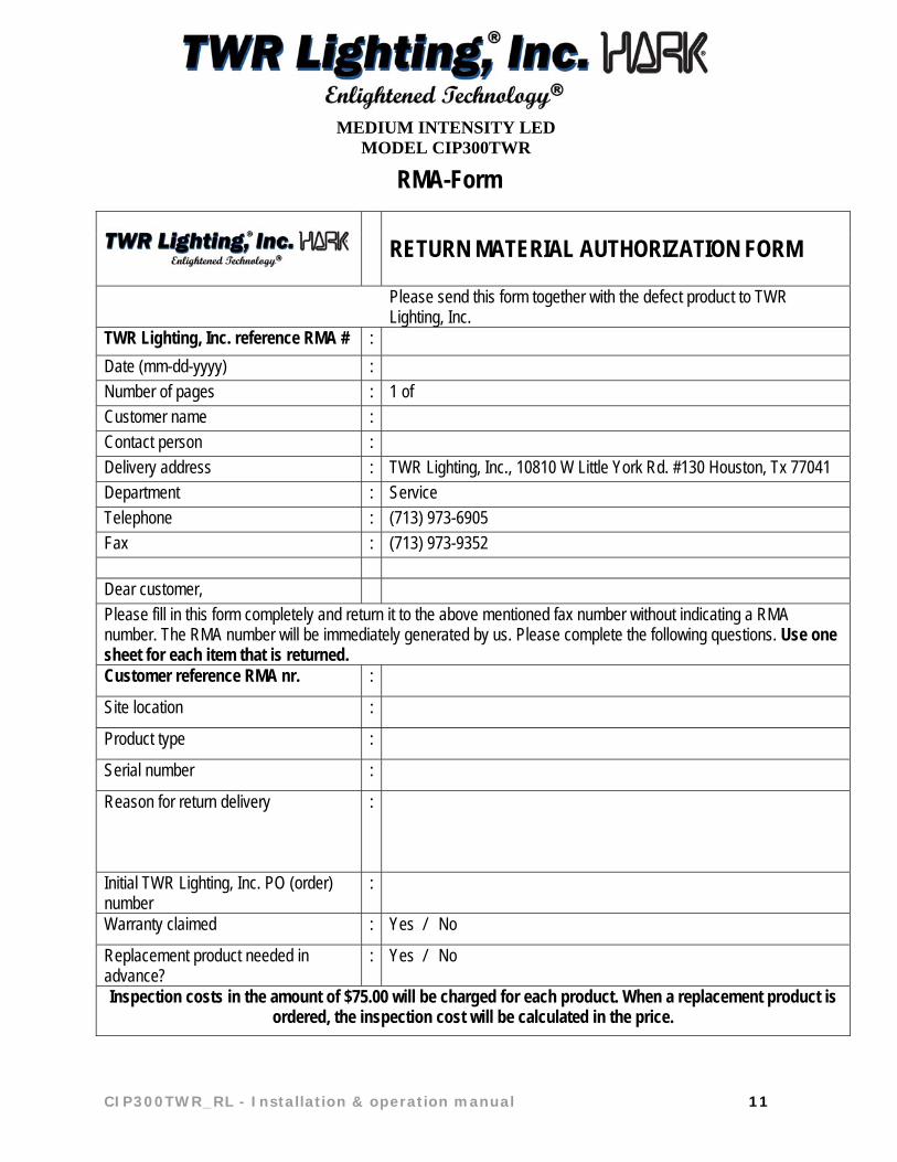
RMA-Form
RETURN MATERIAL AUTHORIZATION FORM
Please send this form together with the defect product to TWR Lighting, Inc.
TWR Lighting, Inc. reference RMA # :
Date (mm-dd-yyyy) :
Number of pages : 1 of Customer name :
Contact person :
Delivery address : TWR Lighting, Inc., 10810 W Little York Rd. #130 Houston, Tx 77041 Department : Service
Telephone : (713) 973-6905
Fax : (713) 973-9352 Dear customer,
Please fill in this form completely and return it to the above mentioned fax number without indicating a RMA number. The RMA number will be immediately generated by us. Please complete the following questions. Use one sheet for each item that is returned. Customer reference RMA nr. :
Site location :
Product type :
Serial number :
Reason for return delivery
:
Initial TWR Lighting, Inc. PO (order) number
:
Warranty claimed : Yes / No
Replacement product needed in advance?
: Yes / No
Inspection costs in the amount of $75.00 will be charged for each product. When a replacement product is ordered, the inspection cost will be calculated in the price.
MEDIUM INTENSITY LED
MODEL CIP300TWR
12 CIP300TWR_RL - Installation & operation manual
1 INTRODUCTION
The CIP300 is a control and monitoring unit for use in TWR Lighting, Inc. Aviation obstacle light systems. The CIP300 may be used in an obstacle light system that includes L450 or L550 medium intensity lights. The CIP300 uses digital data communication technology that allows all of the lights on the system to be connected via a single TWR Lighting, Inc. Strobcable-9 or Strobeline cable. These cables are a combined cable with power and control wires to simplify system installation. The CIP300 includes a simple user interface to allow at site interaction with the controller without the need for any additional equipment or tools. Full access to the facilities and functions of the CIP300 can be accessed by a TWR Lighting, Inc. service engineer. The CIP300 has separate power and control modules, the power module includes Class III over voltage protection devices. Each light has a unique system address which allows the CIP300 to control the operation and monitor the total system condition, and to indicate that real time status of the system including all FAIL conditions as prescribed and specified by FAA and ICAO that need to be advised to third party monitoring services. In addition to these critical FAIL condition alarms other ALARM conditions that indicate the system is operating with some non-critical status indicators outside of the normal mode are identified. All CIP300 system control connections are galvanically isolated.
MEDIUM INTENSITY LED
MODEL CIP300TWR
CIP300TWR_RL - Installation & operation manual 13
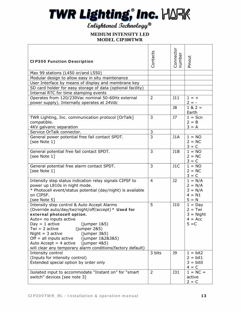
CIP300 Function Description
Con
tact
s
Con
nect
or
num
ber
Pino
ut
Max 99 stations (L450 or/and L550) Modular design to allow easy in situ maintenance User Interface by means of display and membrane key SD card holder for easy storage of data (optional facility) Internal RTC for time stamping events Operates from 120/230Vac nominal 50-60Hz external power supply). Internally operates at 24Vdc
2 J11 1 = + 2 = -
J8 1 & 2 = Earth
TWR Lighting, Inc. communication protocol [OrTalk] compatible. 4KV galvanic separation
3 J7 1 = Scn 2 = B 3 = A
Service OrTalk connector. 3 General power potential free fail contact SPDT. [see Note 1]
3 J1A 1 = NO 2 = NC 3 = C
General potential free fail contact SPDT. [see Note 1]
3 J1B 1 = NO 2 = NC 3 = C
General potential free alarm contact SPDT. [see Note 1]
3 J1C 1 = NO 2 = NC 3 = C
Intensity step status indication relay signals CIPSF to power up L810s in night mode. * Photocell event/status potential (day/night) is available on CIPSF. [see Note 5]
4 J2 1 = N/A 2 = N/A 3 = N/A 4 = N1 5 = N
Intensity step control & Auto Accept Alarms (Override auto/day/twi/night/off/accept) * Used for external photocell option. Auto= no inputs active Day = 1 active (jumper 1&5) Twi = 2 active (jumper 2&5) Night = 3 active (jumper 3&5) Off = all inputs active (jumper 1&2&3&5) Auto Accept = 4 active (jumper 4&5) will clear any temporary alarm conditions(factory default)
5 J10 1 = Day 2 = Twi 3 = Night 4 = Acc 5 =C
Intensity control (Inputs for intensity control) Extended special option by order only
3 bits J9 1 = bit2 2 = bit1 3 = bit0 4 = C
Isolated input to accommodate “Instant on” for “smart switch” devices [see note 3]
2 J31 1 = NC = active 2 = C

MEDIUM INTENSITY LED
MODEL CIP300TWR
14 CIP300TWR_RL - Installation & operation manual
CIP300 Function Description
cont
acts
Con
nect
or
num
ber
Pino
ut
CIPSF input to allow for L810 sync function with L450 or L550 Beacon [see Note 7]
5 J3 1 = +7V 2 = S+ 3 = S- 4 = 0V 5 = Earth
RS485 interface – for TWR Lighting, Inc. use only 3 J6 1 = Scn 2 = B 3 = A
RS232 interface to be used for TWR Lighting, Inc. OSAT (BTP)
3 J4 1 = s 2 = r 3 = gnd
Note 1 : Fail and Alarm indications (J1A / J1B / J1C)
The CIP300 has three relay outputs. These relay outputs are software controlled. During power up (bootmode) all relays are in de-energized state. After the CIP300 has booted properly the relays are set according to the state that the status of the CIP300 dictates. In “power off” and during “boot” all relays are de-energized.
Note 2 : Power fail (J1A) One relay (SPDT) indicating power status. This relay will be connected to the uC and will therefore indicate if the uC is running or not. It will also have a small delay because the uC will continue running for a number of mS after a power fail.
Note 3 : General fail (J1B)
One relay (SPDT) indicating general FAIL alarm status. Missing station Incorrect station compared to configuration parameters Flash fail Photocell fail (system wide) wrong intensity step
MEDIUM INTENSITY LED
MODEL CIP300TWR
CIP300TWR_RL - Installation & operation manual 15
Note 4 : General Alarm (J1C) One relay (SPDT) indicating General Alarm status. The General Alarm conditions are event/status messages that are not critical to correct system operation – but which indicate a system abnormality that should be investigated.
Note 5 : Intensity step status indication relay (J2)
This relay is used to indication mode changes (day and night) to the CIPSF only – DO NOT use to power any other devices. (Photocell event/status potential (day/night/common) is available on CIPSF.)
Note 6 : Smart Switch Devices (J31)
Normally the input will be not connected (= not active) and in that case the system will be set to ‘Instant ON’, which is normal operation, meaning that the system will follow the normal status based on photocell values or the override status (night & day). Activate the input (connected) will switch OFF this function, meaning all lights will be OFF (standby). Once the active input is removed then this might mean that the first flash will be after a maximum of 3 seconds in a 20fpm system and a maximum of 1.5 seconds in a 40fpm system. (Typically used for Radar detection - Instant On.) Regarding priority: 1. Local override = auto, day, twi and night = from key pad 2. Instant ON = auto and off = from J31 3. Remote override inputs = Auto, day, twi, night and off = from J10 Local override (manually with the user interface of the CIP2408) have the highest priority as this allows a technician to control the system independent of the inputs of the CIP300. This can be done either local or remote (OSAT). The next in line is the instant ON, which will allow a customer to force the system in hot-standby (no flashing but ready to go). The next is the remote override inputs (normally used for an external photocell or by a customer to force the system in a specific intensity step PROVIDED none of the other conditions are present).
Note 7 : CIPSF input (J3)
Used for the CIPSF to signal the CIP2408 the synchronization for L810s and L450 or L550s. External GPS or L450 & L550 GPS cannot be activated with the CIPSF feature.

MEDIUM INTENSITY LED
MODEL CIP300TWR
16 CIP300TWR_RL - Installation & operation manual
1.1 User Interface functions
Controls the day, twilight or night light intensity mode setting and the color of the lights in the system according to the ambient light conditions.
Real time clock.
1.2 Overvoltage protection
TWR Lighting, Inc. uses components to provide overvoltage protection on the power supply connections of its obstacle lighting systems. Each system component incorporates a dual protection overvoltage safety device with a combination of gas discharge tubes, metal oxide varistors with inductors in between. The device provides a Class III protection level.
1.3 Customer interface connections
The customer’s interfaces to the system are all protected by the use of opto coupler devices.
CAUTION! It is assumed that the incoming power supply is suitably protected at the site
distribution board.
NOTE! For installations where the light will be exposed to high radio frequency (RF) radiation
please consult TWR Lighting, Inc. prior to installation.

MEDIUM INTENSITY LED
MODEL CIP300TWR
CIP300TWR_RL - Installation & operation manual 17
2 SAFETY PRECAUTIONS
Although TWR Lighting, Inc. has incorporated practical safety precautions always exercise extreme caution when dealing with electrical equipment. The following general safety precautions must be observed during all phases of operation service and repair of this equipment. Failure to comply with these precautions or with specific warnings elsewhere in this manual violates safety standards of design, manufacture and intended use of this equipment. TWR Lighting, Inc. assumes no liability for the customers’ failure to comply with these requirements.
Do not look directly at the light at close range when it may flash or burn as the intensity of the light could result in permanent eye damage.
Do not touch the components of the electrical circuit while the system is in operation. Never adjust or change the settings while the system is "on".
Do not replace components with the power connected.
Always wait for at least 2 minutes after disconnecting the power source before opening or working on any part of the system because dangerous voltages can be stored in capacitors, even if the power is switched off. Observe the flashing power indication LED in the light.
To prevent fire or shock hazard, do not expose the device to rain or moisture while opened.
Should any solid objects or liquid fall into the device while opened, disconnect the system immediately and have it checked by qualified personnel before any further use.
Do not service or maintain the system when distracted or short of sleep.
Maintenance and repair of the opened device under voltage should be avoided if at all possible and when required should be carried out only by a skilled person who is aware of the hazards involved.
Do not install substitute parts or perform any unauthorized modification to the equipment.
WARNING: HIGH VOLTAGE! The device operates at voltage levels that constitute a personnel safety hazard.
Personnel must observe safety regulations at all times.

MEDIUM INTENSITY LED
MODEL CIP300TWR
18 CIP300TWR_RL - Installation & operation manual
3 UNPACKING
3.1 Receiving the equipment
Before unpacking, check if the packing shows any signs of damage. After opening, check the contents against the delivery slip. All items should be inspected separately for visible damage. Report any damage or loss claims immediately to the freight handler and take any necessary steps to protect your rights.
3.2 Handling
The device must always be handled with care.
Labels on the outside of the package show the top and bottom.
Do not change or remove any labels from the equipment.
3.3 Pre installation test
If possible it is recommended that the device is tested on site before it is installed on the site to confirm the correct operation. The device should only be tested under safe and dry conditions. The device can be tested by simply connecting a 120/230 VAC (±10 %), 50-60 Hz power supply to the connection terminals inside the device. The device should start to operate as soon as the power is supplied.
CAUTION! It is assumed that the incoming power supply is suitably protected at the site
distribution board.
MEDIUM INTENSITY LED
MODEL CIP300TWR
CIP300TWR_RL - Installation & operation manual 19
4 INSTALLATION
Read this manual in full before starting.
Check if all connections are tight.
Clean equipment externally and internally if necessary.
Start with the mechanical installation of the devices that are appropriate for your system. Detailed information concerning the mechanical installation of a certain piece of equipment is given in the sub-chapter "Mechanical installation" of that particular piece of equipment.
When deciding on the mounting location take care to ensure sufficient space for the cable entries and to allow the hinged front cover to be opened.
4.1 Mechanical installation
The control panel can be mounted inside or outside (shaded from direct sunlight) on a suitable secure vertical surface. Consideration must be given to accessibility regarding the door opening requirements.
Check after the mechanical installation that all bolts and nuts are fixed tight. Once the mechanical installation has been completed, the external cabling to the
different devices can be made. Make sure that the enclosure is correctly grounded.
4.2 Electrical installation
The TWR Lighting, Inc. medium intensity obstacle light system requires a supply voltage use of 120/230 VAC (±10 %), 50-60 Hz with a single cable run to interconnect the lights and the CIP300 controller.
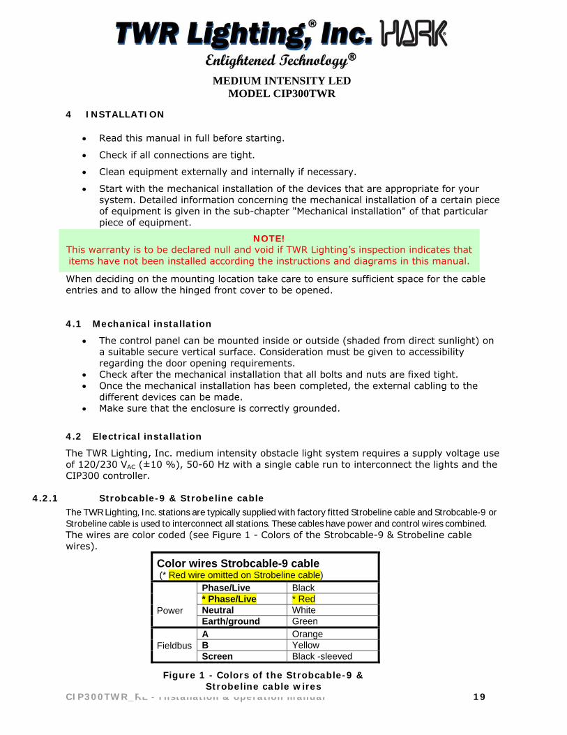
4.2.1 Strobcable-9 & Strobeline cable TheTWRLighting,Inc.stationsaretypicallysuppliedwithfactoryfittedStrobelinecableandStrobcable‐9 or Strobelinecableisusedtointerconnectallstations.Thesecableshavepowerandcontrolwirescombined.The wires are color coded (see Figure 1 - Colors of the Strobcable-9 & Strobeline cable wires).
Color wires Strobcable-9 cable (* Red wire omitted on Strobeline cable)
Power
Phase/Live Black * Phase/Live * Red Neutral White Earth/ground Green
Fieldbus
A Orange B Yellow Screen Black -sleeved
Figure 1 - Colors of the Strobcable-9 & Strobeline cable wires
NOTE! This warranty is to be declared null and void if TWR Lighting’s inspection indicates that items have not been installed according the instructions and diagrams in this manual.
MEDIUM INTENSITY LED
MODEL CIP300TWR
20 CIP300TWR_RL - Installation & operation manual
4.2.2 Client supplied cable In cases where a locally supplied system cable is to be used between the junction boxes and the CIP300 controller then it is probable that separate power and data cables will be used. It is important to use the correct data cable specifications (as Belden 9207 or 89207). The power supply cable core size should be calculated to ensure that the voltage drop does not exceed a difference of 5 % between the CIP300 controller and the farthest light in the system. For the nominal power consumption of each light, see the applicable light manual. Data cable recommended make: Belden 9207 or 89207
1 x twisted pair shielded twinax 100 Ω, 1 mm2 (AWG20), wrapped in aluminum polyester tape, which is covered by a tinned copper braid with an outer PVC (UL 2919) jacket. Operating Voltage: 300 V max Operating temperature: -55 to +85 °C Impedance: 100 Ω (±5 Ω) Capacitance between cores: <60 pF/m Capacitance between screen and core: <80 pF/m Attenuation at 100 MHz: <20 dB/100 m Velocity: 66 % Coverage of the twinax: >85 %
As soon as the mechanical installation has been completed, the external cabling into the controller panel and the other items can be carried out.
Connect the cable to the glands as shown in 4.3 below.
The cable wires shall be terminated to the terminal strip inside the junction box or CIP300 enclosure as appropriate
Check that all system wiring connections are correctly made and that the wires are securely connected on the terminals.
The cables should be tested and checked for earth fault prior to proceeding.
Make sure that the system does not contain two parts with the same station number.
Make a note of the position on the structure of each station number and leave this in the CIP300 enclosure to help with future service work.
The cables should be subjected to a high voltage test and checked for earth faults before applying any power to the system.
CAUTION! It is assumed that the incoming power supply is suitably protected at the site
distribution board.
MEDIUM INTENSITY LED
MODEL CIP300TWR
CIP300TWR_RL - Installation & operation manual 21
4.3 Connecting the Strobcable-9 and Strobeline cable with EMC gland
The screen of the cable, when used with the correct EMC cable glands, provides an effective equipotential bonding system between the system components. This ensures that the secondary lightning current (which there will always be in the event of a lightning discharge because of the impedance of a structure to earth will never be zero) will flow through a controlled path.
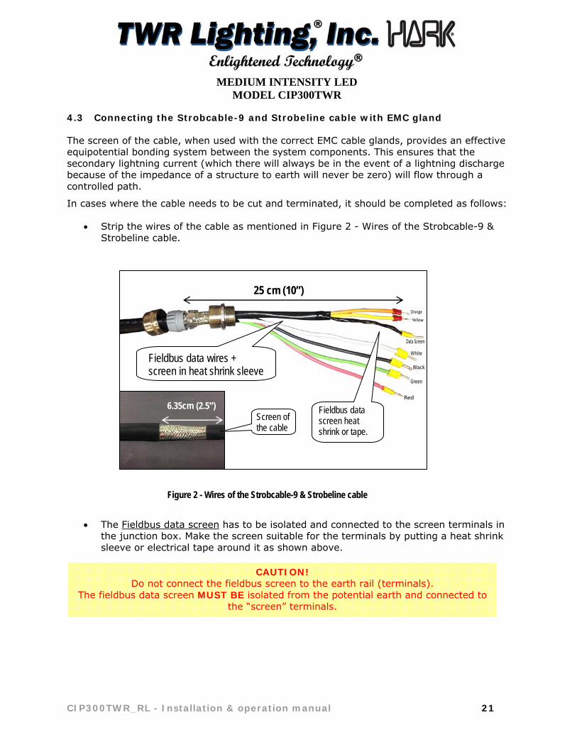
In cases where the cable needs to be cut and terminated, it should be completed as follows:
Strip the wires of the cable as mentioned in Figure 2 - Wires of the Strobcable-9 & Strobeline cable.
The Fieldbus data screen has to be isolated and connected to the screen terminals in
the junction box. Make the screen suitable for the terminals by putting a heat shrink sleeve or electrical tape around it as shown above.
CAUTION! Do not connect the fieldbus screen to the earth rail (terminals).
The fieldbus data screen MUST BE isolated from the potential earth and connected to the “screen” terminals.
Figure 2 - Wires of the Strobcable-9 & Strobeline cable
25 cm (10”)
Fieldbus data screen heat shrink or tape.
Fieldbus data wires + screen in heat shrink sleeve
6.35cm (2.5”) Screen of the cable

MEDIUM INTENSITY LED
MODEL CIP300TWR
22 CIP300TWR_RL - Installation & operation manual
Properly strip and prepare end of the wires. See Figure 3 - Wire Ends. The control wires of the Strobcable-9 and Strobeline cable have a separate screen to prevent signal corruption.
Use electrical tape to secure down 63.5mm (2.5”) end of outer screen. Put the EMC cable gland around the cable as shown in Figure 4 - EMC cable gland – outer screen. Put the metal ring around braided screen as shown.
Figure 3 - Wire ends
Figure 4 - EMC cable gland – outer screen
Phase (Black)
Neutral (White)
G or PE (earth)
Phase (Red) Note: Red wire omitted on
Strobeline cable
Fieldbus/ data wires
Fieldbus data screen must be Isolated (Not a ground!)
Metal ring must be in contact with outer screen
6.35cm (2.5”)
Electrical tape end
Outer screen of the cable
Align plastic grommet with end of cable PVC jacket.

MEDIUM INTENSITY LED
MODEL CIP300TWR
CIP300TWR_RL - Installation & operation manual 23
Make sure that the outer screen is in contact with the metal ring, this to ensure that the device is protected against the effects of lightning discharge electric emissions. See Figure 5 - Cable gland connected to the Strobcable-9 cable. The outer screen/armor is easily unraveled with a small screw driver (DO NOT CUT UNTIL DESIRED LENGTH HAS BEEN UNRAVELED). Leave approximately 2.5 inches of braided screen for cable gland connection and use electrical tape to secure.
Figure 5 - Cable gland connected to the Strobcable-9

MEDIUM INTENSITY LED
MODEL CIP300TWR
24 CIP300TWR_RL - Installation & operation manual
4.4 Fieldbus communication
The TWR Lighting, Inc. Strobcable-9 & Strobeline cable is provided with power and data wires. The orange, yellow and fieldbus screen wires of the cable are used for the fieldbus data communication. The maximum length of a copper fieldbus for reliable operation is 1200 meter (3937 feet) without the use of repeaters. Both ends of the fieldbus have to be terminated with a terminator (resistor of 150 Ω):
The maximum length from a T-junction to a station (light) is 5 meter (16 feet): When a light is installed further away from the fieldbus line on a T-junction of more than 5 meter (16 feet):, a loop via the light must be adopted so that the fieldbus to the light is now a part of the fieldbus line.
Figure 6 - Maximum length of the copper fieldbus
The fieldbus terminator (150 Ω resistor) is a factory fitted item attached to terminal block (see Figure 7 - Fieldbus terminator mounted on the Terminal block) and wired to the back of the (A) orange and (B) yellow terminals in the CIP300 controller and also must be mounted in the furthest junction box typically near the top light.
Figure 7 - Fieldbus terminator mounted on the Terminal block
Max. 1200 meter (3937 feet)
Max. 5 meter (16 feet)
A fieldbus terminator fitted to the A & B terminals
More than 5 meter (16 feet)
MEDIUM INTENSITY LED
MODEL CIP300TWR
CIP300TWR_RL - Installation & operation manual 25
4.5 Earthing of the system
The correct operation and protection of this TWR Lighting, Inc. obstacle light system depends on the system being correctly protected from overvoltage and electrostatic discharges by ensuring that the light system is correctly connected to the earth. The Strobcable-9 & Strobeline cable must be attached to the light fixture and other system enclosures using the provided cable glands according 4.3 above. All light fixtures, junction boxes and the CIP300 enclosure must be directly connected to an earth point with a minimum 6AWG wire. The mounting lug of the light fixture and enclosures may be used as the earth connection point. All mounting brackets in the system must be directly connected to an earth point with a minimum 6AWG wire. If the system is not correctly connected to the earth it may behave erratically, the system components may be damaged, the service life of the system components significantly reduced, and the warranty of the system invalidated.
4.6 Commissioning procedure
Follow the steps on the Commissioning Sheet No special spare parts are needed for the commissioning procedure. The warranty statement as written in this manual is applicable during the installation and commissioning procedure and daily operation. After installation, the system is ready for commissioning.
CAUTION! It is assumed that the incoming power supply is suitably protected at the site
distribution board.

MEDIUM INTENSITY LED
MODEL CIP300TWR
26 CIP300TWR_RL - Installation & operation manual
Obstacle light system commissioning sheet
Use this sheet together with the system diagrams and manuals
Installation Date Site Address
Commissioning Date
Installed by
Commissioned by TWR LIGHTING, INC. Order reference number
System Information Location on structure
Serial Number CIP Controller
Serial Number Light 1
Serial Number Light 2
Serial Number Light 3
Serial Number Light 4
Serial Number Light 5
Serial Number Light 6
Serial Number Light 7
Serial Number Light 8
Serial Number Light 9
Serial Number Light 10
Serial Number Light 11
Serial Number Light 12

MEDIUM INTENSITY LED
MODEL CIP300TWR
CIP300TWR_RL - Installation & operation manual 27
Visual Inspection
Check the lights to make sure that they have not been damaged during installation
Check that all installation terminal connection screws are tight and that the wires are connected according to the applicable interconnection diagrams (Take photos of wiring)
Check electrical connections are properly made (no stray wires and properly connected cable glands etc) “Outer shield grounded in cable gland and inner data shield terminated in junction box.” (Take photos)
Check the lights are installed horizontally - use the level indicator on the lights
Check the mechanical installation (nuts and bolts tight, cables properly secured etc)
Check electrical connections are properly made (no stray wires,
properly connected cable glands etc)
Check all of the system parts are properly grounded
Check that the System Terminators (Resistors) are installed in the right places in accordance with the diagrams. (Take photo)
*Measurements (with a multimeter) “Take photographs”
Check the resistance of the fieldbus is correct before power up the system! (Refer to 6.2 missing station, impedance measurements) Impedance must be within stated parameters. (A to B=80 Ohms, A & B to Screen/Shield must be in K Ohms and Screen/Shield to Line, Neutral and Ground must be in M Ohms If you have question about this important measurement call *TWR Installation Support 713-973-6905 Ext 6.
Check the incoming power supply is the correct voltage and has the correct protection level
Start up Connect the power supply to the system
1. Check that incoming power supply has the correct voltage and proper protection level?
3-phase 208VAC? ( ) Measure each line to Ground L1-( ) L2-( ) L3-( ) Single phase 120VAC? ( ) (Take photos) 2. Check Voltage at very top junction box L to L or N ( ) and L to Ground ( )
Turn on the power supply and allow the system to initialize (approx. 1 minute)
Refer to the system manual to resolve any system faults Contact TWR Lighting, Inc. for support on : Tel 713-973-6905 Installation Support
Figure 8 - Obstacle light system commissioning sheet
MEDIUM INTENSITY LED
MODEL CIP300TWR
28 CIP300TWR_RL - Installation & operation manual
5 START UP THE SYSTEM
Make sure that TWR Lighting, Inc. system components are correctly connected to the CIP300 and that the products are properly closed, before you first turn on the power supply. This will prevent the occurrence of system FAIL and ALARM messages created during the start up of a system that is not ready for operation.
Check the incoming power supply with the correct input power supply for all products connected to the system.
Turn on the power supply. The system will automatically start up. It may take up to 5 minutes for the system to initialize and start to operate correctly.
Initially the lights will start up individually (not synchronized). The lights in the system will then synchronize with each other and operate at the photocell determined ambient light level.
The system automatically checks itself. Check for any alarm messages on the CIP300 display. Check that the system operates correctly.
6 TROUBLESHOOTING 6.1 Missing Station due to no power at the light fixture
1. Check the connections of the Strobcable-9 & Strobeline cable at the light, the local junction box near the light and the CIP.
2. Check if the Strobcable-9 & Strobeline cable connections are correct.
3. Turn on the power supply.
4. If this does not resolve the problem it indicates that the internal power supply of the light is damaged, contact TWR Tel 713-973-6905 Installation Support

MEDIUM INTENSITY LED
MODEL CIP300TWR
CIP300TWR_RL - Installation & operation manual 29
6.2 Missing Station due to no communication with the light
If power is available at the light, check the fieldbus connections of the Strobcable-9 cable at the CIP300 (orange, yellow and screen wires). This can be done by checking the correct installation of the fieldbus by measuring the impedance between the fieldbus wires with the power turned off. The system is fitted with two (2) fieldbus terminators (150 Ω resistors). Take the measurements with the system fully connected to the CIP300 and power TURNED OFF. The values given below are indicative and should be considered as guidelines only. The MΩ fieldbus screen against potential earth measurements especially are subject to humidity levels.
When the fieldbus measurements are found to be correct, a “missing station” message indicates that the communication module of the light is damaged – contact TWR Tel 713-973-6905 Installation Support.
WARNING! The fieldbus shield must be isolated from the earth/ground
All values are indicative. They should be analyzed by using common sense. Especially the MΩ values are subject to external conditions like humidity and moisture.

MEDIUM INTENSITY LED
MODEL CIP300TWR
30 CIP300TWR_RL - Installation & operation manual
6.3 Incorrect day/night mode operation
The obstacle light system is not operating according to the ambient light conditions. The system cannot determine the correct day or night operating mode due to incorrect photocell information. Each light in the system contains a photocell and the CIP300 uses the information from all of these photocells to determine the correct operating mode. If a photocell is damaged then the CIP300 will disregard the information from this photocell and will base the system operation on the information from the remaining photocells. A system wide “photocell fail” is only initiated when there are no remaining operating photocells in the system. The photocells are inherently very reliable so a problem with the photocell part of the light is very unlikely. Check if the photocell has a clear view to be able to measure the ambient light conditions. Do not position the light were the photocell is closely located to an obstacle which can block ambient light conditions. Do not position the light where the photocell is affected by any other light source. Make sure that the photocell is not covered by dirt. Clean the photocell.
MEDIUM INTENSITY LED
MODEL CIP300TWR
CIP300TWR_RL - Installation & operation manual 31
7 CIP300 DISPLAY INFORMATION
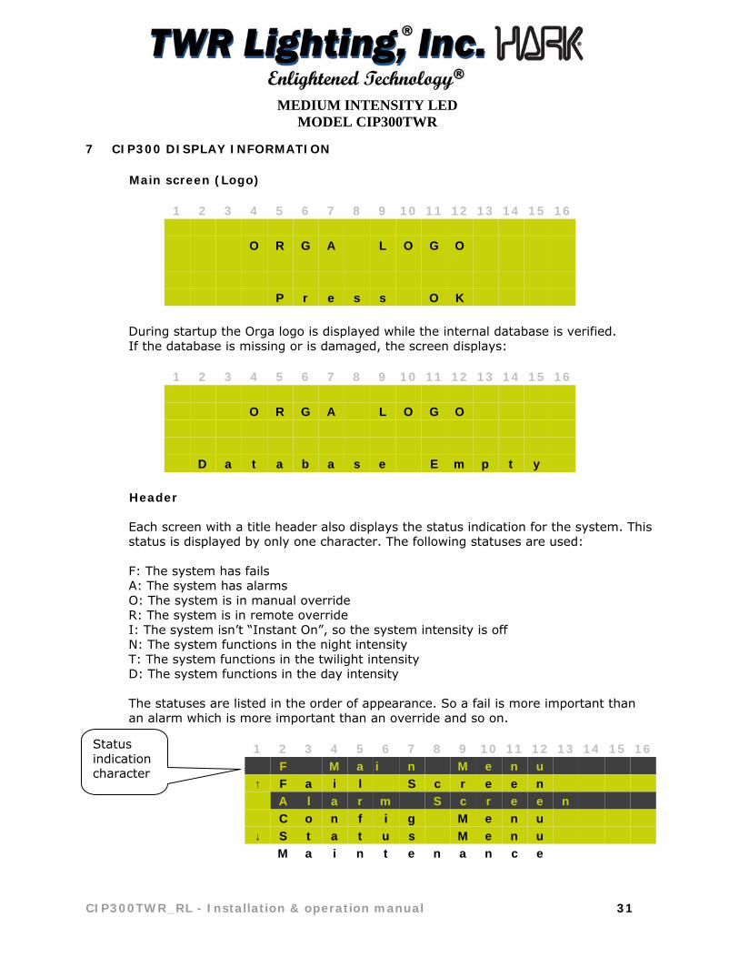
Main screen (Logo)
1 2 3 4 5 6 7 8 9 10 11 12 13 14 15 16 O R G A L O G O P r e s s O K
During startup the Orga logo is displayed while the internal database is verified. If the database is missing or is damaged, the screen displays:
1 2 3 4 5 6 7 8 9 10 11 12 13 14 15 16 O R G A L O G O D a t a b a s e E m p t y
Header
Each screen with a title header also displays the status indication for the system. This status is displayed by only one character. The following statuses are used: F: The system has fails A: The system has alarms O: The system is in manual override R: The system is in remote override I: The system isn’t “Instant On”, so the system intensity is off N: The system functions in the night intensity T: The system functions in the twilight intensity D: The system functions in the day intensity The statuses are listed in the order of appearance. So a fail is more important than an alarm which is more important than an override and so on.
1 2 3 4 5 6 7 8 9 10 11 12 13 14 15 16 F M a i n M e n u ↑ F a i l S c r e e n A l a r m S c r e e n C o n f i g M e n u ↓ S t a t u s M e n u M a i n t e n a n c e
Status indication character

MEDIUM INTENSITY LED
MODEL CIP300TWR
32 CIP300TWR_RL - Installation & operation manual
Main Menu
From the main menu all the functions of the CIP300 can be accessed. Use UP and DOWN to navigate through the menu and use OK to enter the function. If ESC is pressed in any screen, the display returns to the previous screen. The main screen looks like this:
1 2 3 4 5 6 7 8 9 10 11 12 13 14 15 16 F M a i n M e n u ↑ F a i l S c r e e n A l a r m S c r e e n C o n f i g M e n u ↓ S t a t u s M e n u M a i n t e n a n c e
FAIL Alarm screen 1 2 3 4 5 6 7 8 9 10 11 12 13 14 15 16 F F a i l S c r e e n ↑ S t 0 1 L E D F a i l S t 0 2 H i g h T e m p S t 0 4 M i s s i n g ↓ C i 0 1 T e m p ID Channel
To find out details for an individual FAIL / ALARM, use the up/down arrows to select the alarm with the selection bar and press OK.
1 2 3 4 5 6 7 8 9 10 11 12 13 14 15 16 F F a i l I n f o * L 4 5 0 - 6 3 A / 6 3 B - 4 0 - G C h x x H i g h T e m p 1 0 - 0 5 - 1 1 2 1 : 1 2 tag channel
The asterisk in front of the fail description has the following states:
* L 4 5 0 - -> Fail/Alarm is not resolved and not accepted
* L 4 5 0 - -> Fail/Alarm is not resolved and accepted
L 4 5 0 - -> Fail/Alarm is resolved but not accepted

MEDIUM INTENSITY LED
MODEL CIP300TWR
CIP300TWR_RL - Installation & operation manual 33
There are several different messages associated with a missing station: 1 2 3 4 5 6 7 8 9 10 11 12 13 14 15 16 F F a i l I n f o * L 4 5 0 - 6 3 A / 6 3 B - 4 0 - G M i s s i n g 1 0 - 0 5 - 1 1 2 1 : 1 2 tag s channel
In case of incorrect substation (Module type) in relation to the CIP300 configuration – i.e. type of light is present that the CIP300 is not programmed to expect to be in the system
1 2 3 4 5 6 7 8 9 10 11 12 13 14 15 16 F F a i l I n f o * L 4 5 0 - 6 3 A / 6 3 B - 4 0 - G W r o n g T y p e 1 0 - 0 5 - 1 1 2 1 : 1 2 tag s channel
In case of incorrect substation (Sub type) in relation to the CIP300 configuration – i.e. correct type of light (L450) but incorrect version or configuration of light
1 2 3 4 5 6 7 8 9 10 11 12 13 14 15 16 F F a i l I n f o * L 4 5 0 - 6 3 A / 6 3 B - 4 0 - G W r o n g S u b 1 0 - 0 5 - 1 1 2 1 : 1 2 tag s channel
In case of unknown substation (Module type) in relation to the CIP300 configuration – ie a type of light that the CIP300 does not recognize
1 2 3 4 5 6 7 8 9 10 11 12 13 14 15 16 F F a i l I n f o * L 4 5 0 - 6 3 A / 6 3 B - 4 0 - G U n k n . T y p e 1 0 - 0 5 - 1 1 2 1 : 1 2 tag s channel
MEDIUM INTENSITY LED
MODEL CIP300TWR
34 CIP300TWR_RL - Installation & operation manual
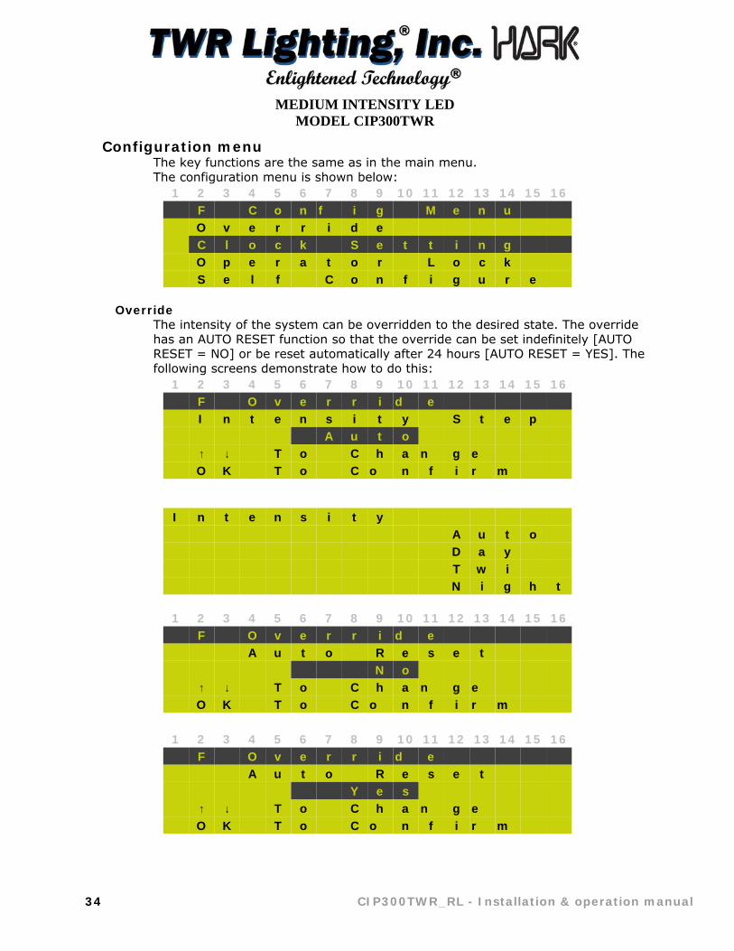
Configuration menu The key functions are the same as in the main menu. The configuration menu is shown below:
1 2 3 4 5 6 7 8 9 10 11 12 13 14 15 16 F C o n f i g M e n u O v e r r i d e C l o c k S e t t i n g O p e r a t o r L o c k S e l f C o n f i g u r e
Override The intensity of the system can be overridden to the desired state. The override has an AUTO RESET function so that the override can be set indefinitely [AUTO RESET = NO] or be reset automatically after 24 hours [AUTO RESET = YES]. The following screens demonstrate how to do this:
1 2 3 4 5 6 7 8 9 10 11 12 13 14 15 16 F O v e r r i d e I n t e n s i t y S t e p A u t o ↑ ↓ T o C h a n g e O K T o C o n f i r m
I n t e n s i t y A u t o D a y T w i N i g h t
1 2 3 4 5 6 7 8 9 10 11 12 13 14 15 16 F O v e r r i d e A u t o R e s e t N o ↑ ↓ T o C h a n g e O K T o C o n f i r m
1 2 3 4 5 6 7 8 9 10 11 12 13 14 15 16 F O v e r r i d e A u t o R e s e t Y e s ↑ ↓ T o C h a n g e O K T o C o n f i r m

MEDIUM INTENSITY LED
MODEL CIP300TWR
CIP300TWR_RL - Installation & operation manual 35
Clock Setting
1 2 3 4 5 6 7 8 9 10 11 12 13 14 15 16
F C L O C K S E T
D A T E ( D D - M M - Y Y )
2 1 - 0 2 - 0 8
↑ ↓ T O C H A N G E
O K T O C O N F I R M
1 2 3 4 5 6 7 8 9 10 11 12 13 14 15 16
F C L O C K S E T
T I M E ( H H : M M : S S )
0 9 : 0 1 : 3 0
↑ ↓ T O C H A N G E
O K T O C O N F I R M
1 2 3 4 5 6 7 8 9 10 11 12 13 14 15 16
F C L O C K S E T
D A Y L I G H T S A V I N G S
↑ ↓ T O C H A N G E
O K T O C O N F I R M
Note: To change the value press OK, if OK is pressed longer than 4 sec than the value increases in tenths. The update rate is 0.5s. Status Screen
The status of a substation or of the CIP300 can be displayed. The status screen is an option and this must be enabled to enter this screen. The screen looks like this:
1 2 3 4 5 6 7 8 9 10 11 12 13 14 15 16 F S t a t u s S c r e e n S t a t i o n N o 0 1 E n t e r i n g 0 0 W i l l S h o w T h e C I P 3 0 0 P r o p e r t i e s
By pressing UP or DOWN the station number can be changed. ESC returns to the Main Menu and OK is used to view the status of the requested station.

MEDIUM INTENSITY LED
MODEL CIP300TWR
36 CIP300TWR_RL - Installation & operation manual
For the CIP300 status the Station No “00” has to be entered, and all the other numbers are for the status of the substations starting at “01”. If a station isn’t present the next screen is displayed:
1 2 3 4 5 6 7 8 9 10 11 12 13 14 15 16 F S t a t u s S c r e e n S t a t i o n N o 0 1 S t a t i o n N o t P r e s e n t !
Substation Status Screen
The status of the substations is displayed by using three screens. By pressing UP or DOWN the pages are changed. To return to the selection screen the ESC key must be used. The initial screen contains the station number, the module type and subtype:
1 2 3 4 5 6 7 8 9 10 11 12 13 14 15 16 F S t a t u s S c r e e n S t a t i o n : 0 1 S t a t i o n T y p e : L 4 5 0 - ↓ 6 3 A / 6 3 B - 4 0 - G
If you press down, the next screen displays the software versions of the application and the bootROM, the hardware version and the hardware variation.
1 2 3 4 5 6 7 8 9 10 11 12 13 14 15 16 F S t a t u s S c r e e n ↑ A p p V e r : 1 . 0 5 B R O M V e r : 1 . 0 7 H W V e r : 1 1 . 2 ↓ H W V a r : 0 0
Note: The hardware version consists of the cardcode followed by a dot and the board revision.

MEDIUM INTENSITY LED
MODEL CIP300TWR
CIP300TWR_RL - Installation & operation manual 37
If the station is still in the bootROM status the application version can’t be displayed, so this text is replaced by the text “BootROM Mode”.
1 2 3 4 5 6 7 8 9 10 11 12 13 14 15 16 F S t a t u s S c r e e n ↑ A p p V e r s i o n : B o o t R O M M o d e B R o m V e r s i o n : ↓ 3 3 2 0 A 1 . 0 3
If you press page down again you enter the next screen with even more information. If the station has rotary switches the screen looks like this:
1 2 3 4 5 6 7 8 9 10 11 12 13 14 15 16 F S t a t u s S c r e e n ↑ R o t S W : 9 - 8 - 0 - 1 S N : 1 2 3 4 5 6 7 8 9 0 1 2 3 4 5 6 7 8
If the station doesn’t have rotary switches:
1 2 3 4 5 6 7 8 9 10 11 12 13 14 15 16 F S t a t u s S c r e e n ↑ S N : 1 2 3 4 5 6 7 8 9 0 1 2 3 4 5 6 7 8
Note: If the station only has a short serial number, the second line isn’t used and the first line contains the short serial number. If the system is in bootROM mode the serial number and the rotary switches can’t be read. The following is displayed:
1 2 3 4 5 6 7 8 9 10 11 12 13 14 15 16 F S t a t u s S c r e e n ↑ S N : x x x x x x x x x x x

MEDIUM INTENSITY LED
MODEL CIP300TWR
38 CIP300TWR_RL - Installation & operation manual
CIP Status Screen The status of the CIP300 is displayed by using four screens. By pressing UP or DOWN the pages are changed. To return to the selection screen the ESC key must be used.
1 2 3 4 5 6 7 8 9 10 11 12 13 14 15 16 F C I P 3 0 0 S t a t u s T y p e N a m e : C I P 3 0 0 - x x x A p p V e r s i o n : ↓ 1 . 0 5
Screen 1: This screen shows 15 characters of the Type Name (which contains 20 characters) and version of the application.
1 2 3 4 5 6 7 8 9 10 11 12 13 14 15 16 F C I P 3 0 0 S t a t u s ↑ B R o m V e r s i o n : 1 . 0 7 L a s t C o n f i g : ↓ 2 6 - 0 5 - 1 0
Screen 2: This screen displays the bootROM version and the last configuration date.
1 2 3 4 5 6 7 8 9 10 11 12 13 14 15 16 F C I P 3 0 0 S t a t u s ↑ C I P N u m b e r : 0 1 H W V e r : 2 3 . 2 D u a l L i g h t : O n ↓ M a i n S t a n d : O f f
Screen 3: The CIP station number, the hardware version, the dual-lighting state and the main-standby state are displayed here.
The last screen has two versions, depending on what serial number has been set:
1 2 3 4 5 6 7 8 9 10 11 12 13 14 15 16 F C I P 3 0 0 S t a t u s ↑ S e r i a l N u m b e r : A 0 0 0 0 0 1 2 3 D 4
Screen 4: This screen shows the short serial number of the CIP300.

MEDIUM INTENSITY LED
MODEL CIP300TWR
CIP300TWR_RL - Installation & operation manual 39
1 2 3 4 5 6 7 8 9 10 11 12 13 14 15 16 F C I P 3 0 0 S t a t u s ↑ S e r i a l N u m b e r : 1 2 3 4 5 6 7 8 9 0 1 2 3 4 5 6 7 8
Screen 4: This screen shows the long serial number of the CIP300.
Maintenance Screen
The key functions are the same as in the main menu (0). The maintenance menu is depicted below:
1 2 3 4 5 6 7 8 9 10 11 12 13 14 15 16 F M a i n t e n a n c e ↑ S h o w S t a t i o n s R e s e t S t a t i o n s S h o w S y s I n f o ↓ E x t e r n a l M e m o r y G P S S t n I n f o
Show Stations
1 2 3 4 5 6 7 8 9 10 11 12 13 14 15 16 F S h o w S t n ↑ C o n f i g u r e d * 1 0 1 0 2 0 4 0 6 0 7 0 8 0 9 9 8 ↓ N o t C o n f i g * 2 0 3 0 5 M a s t e r s 0 1 D u m m i e s 0 2 S e r v i c e T o o l s 0 1 U n d e f i n e d S u b s 0 2
MEDIUM INTENSITY LED
MODEL CIP300TWR
40 CIP300TWR_RL - Installation & operation manual
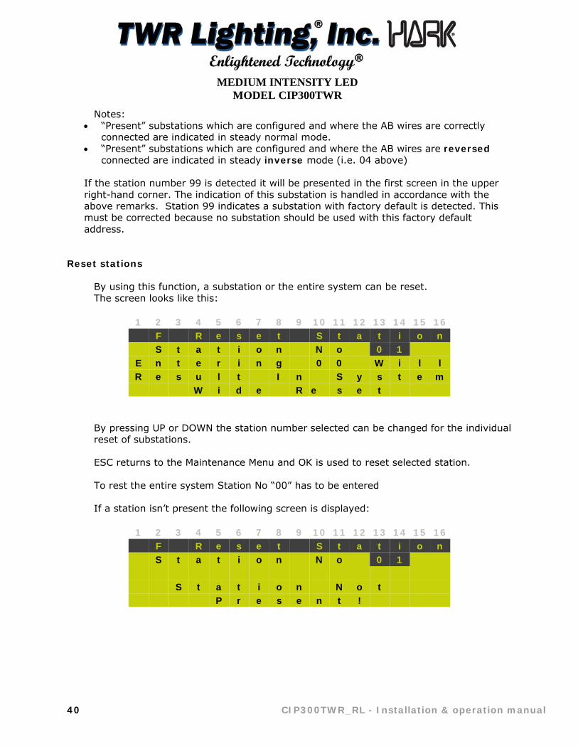
Notes: “Present” substations which are configured and where the AB wires are correctly
connected are indicated in steady normal mode. “Present” substations which are configured and where the AB wires are reversed
connected are indicated in steady inverse mode (i.e. 04 above)
If the station number 99 is detected it will be presented in the first screen in the upper right-hand corner. The indication of this substation is handled in accordance with the above remarks. Station 99 indicates a substation with factory default is detected. This must be corrected because no substation should be used with this factory default address.
Reset stations
By using this function, a substation or the entire system can be reset. The screen looks like this:
1 2 3 4 5 6 7 8 9 10 11 12 13 14 15 16 F R e s e t S t a t i o n S t a t i o n N o 0 1 E n t e r i n g 0 0 W i l l R e s u l t I n S y s t e m W i d e R e s e t
By pressing UP or DOWN the station number selected can be changed for the individual reset of substations. ESC returns to the Maintenance Menu and OK is used to reset selected station. To rest the entire system Station No “00” has to be entered If a station isn’t present the following screen is displayed:
1 2 3 4 5 6 7 8 9 10 11 12 13 14 15 16 F R e s e t S t a t i o n S t a t i o n N o 0 1 S t a t i o n N o t P r e s e n t !
MEDIUM INTENSITY LED
MODEL CIP300TWR
CIP300TWR_RL - Installation & operation manual 41
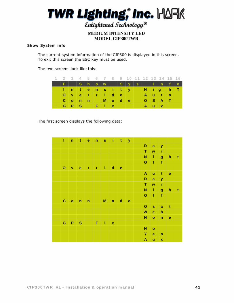
Show System info
The current system information of the CIP300 is displayed in this screen. To exit this screen the ESC key must be used. The two screens look like this:
1 2 3 4 5 6 7 8 9 10 11 12 13 14 15 16 F S h o w S y s I n f o I n t e n s i t y N i g h T O v e r r i d e A u t o C o n n M o d e O S A T ↓ G P S F i x A u x
The first screen displays the following data:
I n t e n s i t y D a y T w i N i g h t O f f O v e r r i d e A u t o D a y T w i N i g h t O f f C o n n M o d e O s a t W e b N o n e G P S F i x N o Y e s A u x

MEDIUM INTENSITY LED
MODEL CIP300TWR
42 CIP300TWR_RL - Installation & operation manual
The second screen shows the following variables: The auto acceptance state, the instant on state, the reduced intensity percentage and the type of sync message.
1 2 3 4 5 6 7 8 9 10 11 12 13 14 15 16 F S h o w S y s I n f o ↑ A u t o A c c . O f f I n s t a n t O n N o R e d u c e d % 1 0 0 S y n c M s g O l d
These are all the possible variations of the displayed data:
A u t o A c c . O n O f f I n s t a n t O n Y e s N o
R e d u c e d % 1 0 0 3 0 1 0 . . . S y n c M s g O l d N e w

MEDIUM INTENSITY LED
MODEL CIP300TWR
CIP300TWR_RL - Installation & operation manual 43
GPS Stations This screen is used for displayed the number of stations which can currently synchronize the system. If there aren’t any stations that can do that, the following screen is shown:
1 2 3 4 5 6 7 8 9 10 11 12 13 14 15 16 F G P S S t n I n f o
G P S S t a t i o n s : 0 0
If there is at least one station that can currently synchronize, the next screen is displayed:
1 2 3 4 5 6 7 8 9 10 11 12 13 14 15 16 F G P S S t n I n f o
G P S S t a t i o n s : 0 2 C u r r e n t G P S : 0 1 F i x T y p e : 3 d
The following variables are used:
F i x T y p e : A u x 2 d 3 d

MEDIUM INTENSITY LED
MODEL CIP300TWR
44 CIP300TWR_RL - Installation & operation manual
8 MAINTENANCE
The CIP300 is designed as a maintenance free device once the connections are properly and securely made and tested.
The power supply should be isolated prior to the execution of any maintenance work.
During service visits, it only needs to be checked that:
the unit is securely mounted to the structure;
there are no signs of mechanical damage to the enclosure;
the enclosure is securely closed;
the enclosure is connected to earth;
the device is being kept clean;
the inside shows no signs of water ingress (condensation, dry water marks etc). Clean it if necessary;
the ingress protection (cable and gland connections + door sealing: condition of the gasket and mounting hole and screws) is still present;
the breather (at the bottom of the enclosure) is open and free of dirt;
the printed circuit boards and electrical connections are checked for tightness, absence of corrosion and high-voltage damage. Clean or replace any device that shows dirt or marks of high-voltage damage;
the Strobcable-9 & Strobeline cable connection to the EMC gland is correct. The connection has to be tight and protective against dirt and moisture ingress. Ensure that the Strobcable-9 cable is securely fastened at & Strobeline short intervals to the structure or supporting parts;
the wire connections to the terminals are secure;
the locking screws are not severely corroded and move freely;
Close the enclosure.

MEDIUM INTENSITY LED
MODEL CIP300TWR
CIP300TWR_RL - Installation & operation manual 45
9 COMPONENT AND SPARE PARTS LIST
No spare parts are expected to be needed during the warranty period neither during the commissioning procedure. In case a site requires maintaining some spare parts at hand, the ‘SP’ marked parts can be bought in advance. The warranty statement as written in this manual is applicable during the installation and commissioning procedure and daily operation.
Qty. DESCRIPTION PART NUMBER SP PICTURE
2 1 AMP Fuse KTK-1 Y
2 3 AMP Fuse KTK-3 Y
2 5 AMP Fuse KTK-5 Y
2 10 AMP Fuse FNQ-10 Y
1 LED SIDELIGHT ALARM CURRENT SENSOR RM22JA31MR Y
1 SURGE PROTECTOR DTK-120HW Y
1 POWER SUPPLY MDR-20-24 N
1 CIP2408 MODULE 017572 N
1 CIP Synchronized Flasher CIPSF
6 END STOP 8WA1808 N
5 SINGLE POLE TERMINAL 8WA1204 N
3 FUSE HOLDER USM-1 N
1 RESISTOR 150 OHM .125W N
1 2 POSITION PLUG STT60043 N
2 5 POSITION PLUG STT60044 N
1 2 POSITION PLUG STT60045 N
1 3 POSITION PLUG STT60046 N
1 9 POSITION PLUG STT60047 N

MEDIUM INTENSITY LED
MODEL CIP300TWR
46 CIP300TWR_RL - Installation & operation manual
10 DRAWINGS / WIRING DIAGRAMS
* * * * *


1 1
2 2
3 3
4 4
AA
BB
DR
AWN
gseb
ekCH
ECKE
D
QA
MFG
APPR
OVE
D
8/18
/200
4
TITL
E
SIZE B
SCAL
E
DW
G N
O
1006
56i_
RCRE
V C
SHEE
T 1
OF
1
Part
s Li
stD
ESCR
IPTI
ON
PART
NU
MBE
RQ
TYIT
EML8
10 O
BSTR
UCT
ION
LIG
HT
OL1
VLED
21
1O
L 6L
ED B
ASE
PLAT
E10
0588
_RE
11.
1O
L 6L
ED S
TAR
DIS
K10
0591
11.
2O
L1/2
SER
IAL
# L
ABEL
1006
801
1.3
5/32
" ID
RU
BBER
GRO
MM
ETA1
0290
11.
4LE
D L
AMP
STD
0500
86
1.5
OL
GAS
KET
OLG
11.
6SI
DEL
IGH
T LE
NS
CLEA
R AC
YRLI
CAP
1008
461
1.7
LEN
S H
OLD
ER R
ING
106V
11.
8LE
D V
ERTI
CAL
PCB
STE0
1-04
76
1.9
1/8
X .4
5 SS
PO
P RI
VET
18PR
SS16
1.10
POW
ER S
UPP
LYPS
90-2
60/2
41
1.11
#20
AWG
RED
BEL
DO
N W
IRE
20RE
D1
1.12
BLU
E W
IRE
NU
TW
IREN
UTB
LU2
1.13
SID
ELIG
HT
LATC
HH
C255
SS2
21/
16 H
OL
7X7
S.S.
WIR
E7X
7SS
13
OL
LEN
S CL
IP12
V245
24
SIN
GLE
SID
ELIG
HT
BOD
Y10
5V1
58-
32 X
1/4
PH
SS
SLO
T SC
REW
832X
14PH
26
STAK
ON
CRI
MP
A1A
27
3/4"
CO
ND
UIT
LO
CKN
UT
GAL
V.A3
141
8
120-
240V
AC
BLACK
WHITE
-+
FIXT
URE
SCHEMATIC
* G
RO
UN
D W
IRE
MU
ST
BE
CO
NN
ECTE
D
TO P
RO
PE
RLY
PR
OTE
CT
PO
WER
SU
PP
LY.
FAIL
UR
E TO
GR
OU
ND
WIL
L VO
ID A
LLW
ARR
ANTI
ES
.
OL1
VLED
2 12
0-24
0VAC
FAA
-OL1
6LED
(L81
0 O
BSTR
UCT
ION
LIG
HT)
* =
ITE
MS
NO
T SH
OW
N
*
4.81
3
7.34
2
_En
light
ened
Tec
hnol
ogy
_
TWR
Lig
htin
g, In
c.
1
6 4 5 8
2
7 3
* * * * * * * * * * * *
1
1
2
2
3
3
4
4
A A
B B
Parts ListDESCRIPTIONPART NUMBERQTYITEM
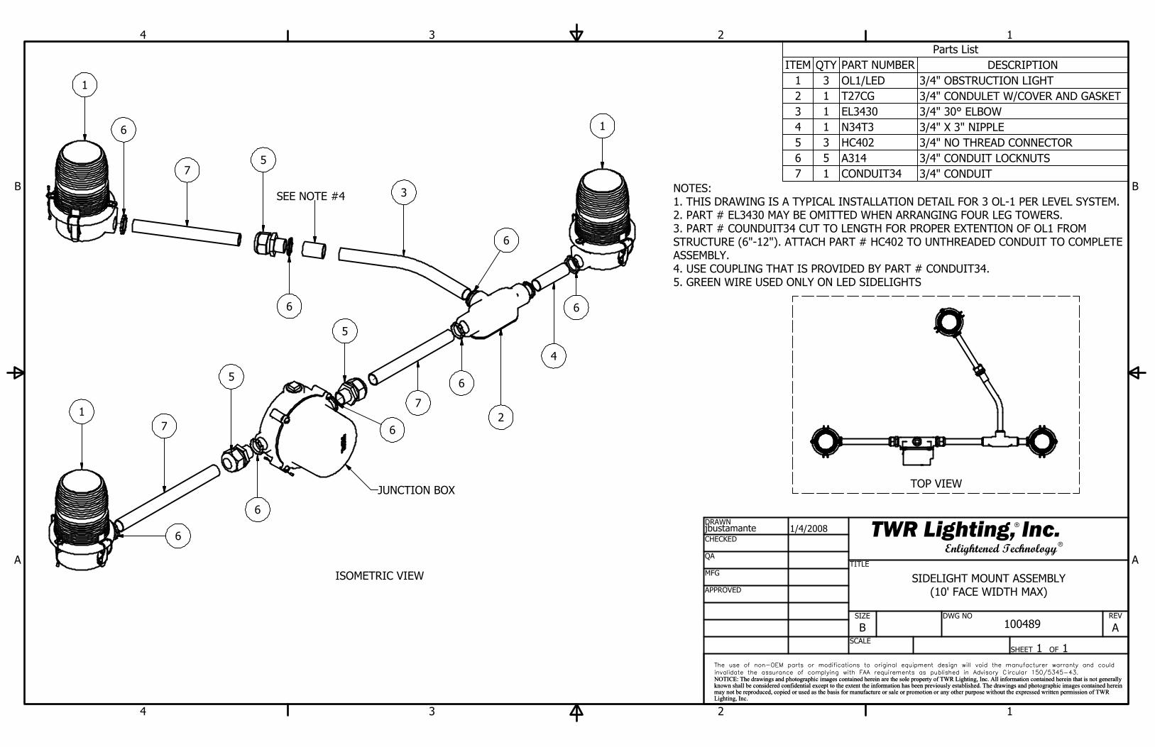
3/4" OBSTRUCTION LIGHTOL1/LED313/4" CONDULET W/COVER AND GASKETT27CG123/4" 30° ELBOWEL3430133/4" X 3" NIPPLEN34T3143/4" NO THREAD CONNECTORHC402353/4" CONDUIT LOCKNUTSA314563/4" CONDUITCONDUIT3417
DRAWNjbustamanteCHECKED
QA
MFG
APPROVED
1/4/2008
TITLE
SIZE
BSCALE
DWG NO
REV
SHEET 1 OF 1 The use of non-OEM parts or modifications to original equipment design will void the manufacturer warranty and could
invalidate the assurance of complying with FAA requirements as published in Advisory Circular 150/5345-43.
NOTICE: The drawings and photographic images contained herein are the sole property of TWR Lighting, Inc. All information contained herein that is not generally known shall be considered confidential except to the extent the information has been previously established. The drawings and photographic images contained hereinmay not be reproduced, copied or used as the basis for manufacture or sale or promotion or any other purpose without the expressed written permission of TWRLighting, Inc.
The use of non-OEM parts or modifications to original equipment design will void the manufacturer warranty and could
invalidate the assurance of complying with FAA requirements as published in Advisory Circular 150/5345-43.
NOTICE: The drawings and photographic images contained herein are the sole property of TWR Lighting, Inc. All information contained herein that is not generally known shall be considered confidential except to the extent the information has been previously established. The drawings and photographic images contained hereinmay not be reproduced, copied or used as the basis for manufacture or sale or promotion or any other purpose without the expressed written permission of TWRLighting, Inc.
Enlightened TechnologyTWR Lighting, Inc.
NOTES:1. THIS DRAWING IS A TYPICAL INSTALLATION DETAIL FOR 3 OL-1 PER LEVEL SYSTEM.2. PART # EL3430 MAY BE OMITTED WHEN ARRANGING FOUR LEG TOWERS.3. PART # COUNDUIT34 CUT TO LENGTH FOR PROPER EXTENTION OF OL1 FROM STRUCTURE (6"-12"). ATTACH PART # HC402 TO UNTHREADED CONDUIT TO COMPLETE ASSEMBLY.4. USE COUPLING THAT IS PROVIDED BY PART # CONDUIT34.5. GREEN WIRE USED ONLY ON LED SIDELIGHTS
TOP VIEW
ISOMETRIC VIEW SIDELIGHT MOUNT ASSEMBLY(10' FACE WIDTH MAX)
100489 A
1
6
75
6
3
6
1
6
4
27
6
5
7
5
6
6
1
6
JUNCTION BOX
SEE NOTE #4
_
_


![Hark Hark [E,134 bpm,6/8] - Brentwood Benson...Hark [G, 134 bpm, 6/8] [Hillsong Worship] Intro |G.\.|.Csus2.Cmaj9.|.Dsus.\.|.Em7..\.| Verse.1 Csus2.Cmaj9 Hark.the.herald.angels.sing](https://static.fdocuments.in/doc/165x107/60d22042ffbbf117fb1a77a3/hark-hark-e134-bpm68-brentwood-benson-hark-g-134-bpm-68-hillsong.jpg)

