Invitation to Bid (ITB) FM52102 D5 Chemical Storage ...
317
Invitation to Bid (ITB) FM52102 D5 Chemical Storage Building Remodel IDAHO TRANSPORTATION DEPARTMENT District 5 5151 South 5 th Ave. Pocatello, Idaho 83204 Date of Issuance: September 1, 2020
Transcript of Invitation to Bid (ITB) FM52102 D5 Chemical Storage ...
Invitation to Bid (ITB) FM52102
D5 Chemical Storage Building Remodel
IDAHO TRANSPORTATION DEPARTMENT
District 5 5151 South 5th Ave.
Pocatello, Idaho 83204
Date of Issuance: September 1, 2020
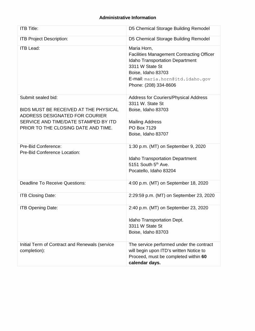
Administrative Information
ITB Title: D5 Chemical Storage Building Remodel
ITB Project Description: D5 Chemical Storage Building Remodel
ITB Lead:
Maria Horn, Facilities Management Contracting Officer Idaho Transportation Department 3311 W State St Boise, Idaho 83703 E-mail: [email protected] Phone: (208) 334-8606
Submit sealed bid: BIDS MUST BE RECEIVED AT THE PHYSICAL ADDRESS DESIGNATED FOR COURIER SERVICE AND TIME/DATE STAMPED BY ITD PRIOR TO THE CLOSING DATE AND TIME.
Address for Couriers/Physical Address 3311 W. State St Boise, Idaho 83703 Mailing Address PO Box 7129 Boise, Idaho 83707
Pre-Bid Conference: Pre-Bid Conference Location:
1:30 p.m. (MT) on September 9, 2020 Idaho Transportation Department 5151 South 5th Ave. Pocatello, Idaho 83204
Deadline To Receive Questions:
4:00 p.m. (MT) on September 18, 2020
ITB Closing Date:
2:29:59 p.m. (MT) on September 23, 2020
ITB Opening Date:
2:40 p.m. (MT) on September 23, 2020 Idaho Transportation Dept. 3311 W State St Boise, Idaho 83703
Initial Term of Contract and Renewals (service completion):
The service performed under the contract will begin upon ITD’s written Notice to Proceed, must be completed within 60 calendar days.
ADVERTISEMENT FOR BIDS AB - 1 BOILERPLT-2009 dbb.doc (rev. 06/03/19) FM52102 D5 Chemical Storage Building Remodel
CONTENTS ADVERTISEMENT FOR BIDS AB-1 INSTRUCTIONS TO BIDDERS ITB-1 – ITB-7 BID PROPOSAL BP-1 – BP-3 CONTRACTOR’S AFFIDAVIT CONCERNING ALCOHOL & DRUG-FREE WORKPLACE BP-4
BIDDER’S ACKNOWLEDGEMENT STATEMENT BP-5 – BP-6 AGREEMENT – FIXED PRICE CONSTRUCTION CONTRACT FPCC-1 EXHIBIT A – OWNER’S PROJECT IDENTIFICATION INFORMATION FPCC-2
EXHIBIT B – ADDRESSES AND AUTHORIZED REPRESENTATIVES FPCC-3
EXHIBIT C – LIST OF DRAWINGS AND SPECIFICATIONS FPCC-4
EXHIBIT D - CONTRACTOR'S AFFIDAVIT CONCERNING TAXES FPCC-5
EXHIBIT E – NAMED SUBCONTRACTORS FPCC-6
EXHIBIT F – NOTICE TO PROCEED FPCC-7
EXHIBIT G - CONTRACTOR’S REQUEST FOR TAX RELEASE FPCC-8
EXHIBIT H - RELEASE OF CLAIMS FPCC-9
EXHIBIT J – CONDITIONS PRECEDENT TO FINAL PAYMENT FPCC-10 EXHIBIT L – PROJECT FINALIZATION AND START FPCC-11 DIVISION 1 - GENERAL REQUIREMENTS
ADVERTISEMENT FOR BIDS AB - 2 BOILERPLT-2009 dbb.doc (rev. 06/03/19) FM52102 D5 Chemical Storage Building Remodel
LEGAL NOTICE - ADVERTISEMENT FOR BIDS In accordance with Idaho Code 67-5711, The Idaho Transportation Department will accept sealed bids for Project #FM52102, D5 Chemical Storage Building Remodel. Bids packets will be accepted at the Idaho Transportation Department at 3311 W State St, Boise, Idaho, 83703, until 2:29:59 p.m. (MST) on September 23, 2020 according to the Bid Package Schedule deadline. The Invitation to Bid package can be found at the following address: http://itd.idaho.gov “Other Solicitations” tab. A public bid opening will be held at the Idaho Transportation Department following the closing time for receipt of bids. Bidders and other properly interested parties are invited to be present at bid opening. A pre-bid site tour will be held at 1:30 p.m. on September 9, 2020 at 5151 South 5th Ave., Pocatello, Idaho. Attendance by bidders is STRONGLY RECOMMENDED. Failure to account for all subjects observed and discussed at the Pre-Bid Meeting will not be a cause for a change order. Each bid must be accompanied by a bid bond with a surety company licensed to do business in Idaho or a certified or cashier’s check drawn on an Idaho bank in an amount not less than 5% of the total bid made payable to Idaho Transportation Department. The bidder, in the event of failure to sign the contract or furnish the necessary 100% performance bond and the necessary 100% payment bond, will forfeit this surety. Bidders shall be properly registered in the State of Idaho, in accordance with the Department of Self Governing Agencies as a “Contractor” licensed in the State of Idaho, in accordance with provisions of an act known as “Public Works Contractor’s State License Law, Title 54, Chapter 19, Idaho Code Amended”. Bidders shall be registered with the Idaho Secretary of State’s office to do business in the State of Idaho. Before any contract is awarded for the work contemplated herein, Idaho Transportation Department shall conduct such investigation, as it deems necessary to determine the performance record and ability of the apparent low bidder to perform the type and size of project specified under this contract. Upon request, the bidder shall submit such information as deemed necessary for such evaluation.
INSTRUCTIONS TO BIDDERS ITB-1 BOILERPLT-2009 dbb.doc (rev. 06/03/19) FM52102 D5 Chemical Storage Building Remodel
INSTRUCTIONS TO BIDDERS GENERAL PROVISIONS DEFINITIONS: Capitalized terms used in these Instructions to Bidders (“Instructions”) shall have the meaning given to them in the Idaho Transportation Department’ Fixed Price Construction Contract Between Owner and Contractor.
HEADINGS: Headings used in these Instructions are for convenience only.
REJECTION OF BIDS, WAIVER OF INFORMALITIES OR CANCELLATION: Prior to the effective date of a contract, the Administrator of the Idaho Transportation Department shall have the right to accept or reject all bids, to waive any minor deviations/informalities or to cancel the bid. ORAL INFORMATION: Questions concerning a bid must be directed in writing to the designated Design Professional (architect or engineer) no less than ten (10) calendar days before bids are due unless provided otherwise via an addendum. Oral information is not binding and any reliance by a bidder on any oral information or representation is at the bidder’s sole risk. Any information given a prospective bidder in response to a written question will be provided to all prospective bidders by an addendum, if such information is necessary for purposes of submitting a bid or if failure to give such information would be prejudicial to uninformed bidders.
PUBLIC RECORDS: The Idaho Public Records Law, Title 74, Chapter 1, Idaho Code, allows the open inspection and copying of public records. Public records include any writing containing information relating to the conduct or administration of the public's business prepared, owned, used or retained by a State or local agency regardless of the physical form or character. Unless exempted by the Public Records Law, your bid will be a public record subject to disclosure under the Public Records Law. Any questions regarding the applicability of the Public Records Law should be addressed to your legal counsel prior to submission.
FORM OF AGREEMENT: Unless otherwise specified in the bid documents, the agreement between the successful bidder and the Owner (“State of Idaho”) shall be the Idaho Transportation Department’ Fixed Price Construction Contract between Owner and Contractor.
PERFORMANCE AND PAYMENT BONDS: A performance bond and payment bond are required for this Project, each in an amount of not less than one hundred percent (100%) of the Contract Price. The performance and payment bonds shall be AIA Document A312, 1984 or the most recent Edition, or a standard surety form certified approved to be the same as the AIA A312 form and shall be executed by a surety or sureties reasonably acceptable to the Owner and authorized to do business in the State of Idaho. Bonds must be provided within ten (10) calendar days following receipt of a Notice of Intent to Award. BID SUBMISSION PROCESS BID DOCUMENTS: The bid documents are available from the Design Professional or as provided in the Invitation to Bid or advertisement for bids. The responsibility is on the bidder to use a complete set of bid documents to prepare its bid and neither the Owner nor the Design Professional shall incur any liability for the bidder’s failure to do so. Bidders obtain no ownership interest or any use rights, except to use in preparation of their bid, by issuance of the bid documents.
INSTRUCTIONS TO BIDDERS ITB-2 BOILERPLT-2009 dbb.doc (rev. 06/03/19) FM52102 D5 Chemical Storage Building Remodel
Bidders and Sub-bidders shall field verify all dimensions pertaining to the Work and shall be responsible for the determination of all quantities of materials required for the completion of the Work. The bidder shall not rely on the scale drawings of the Bidding Documents in his determination of required materials quantities. No allowance shall be made for Bidder’s failure to field-verify dimensions. If a deposit is required, the deposit will be returned to a bidder returning the complete bid documents in good condition no more than twenty (20) days after a Notice of Intent is issued and the amount of any deposit returned may be reduced if the bid documents returned are not complete or are damaged. A bidder awarded a Contract may also keep the bid documents and any deposit will be returned. ADDENDA: In the event it becomes necessary to revise any part of the bid documents, addenda will be issued. Information given to one bidder will be available to all other bidders if such information is necessary for purposes of submitting a bid or if failure to give such information would be prejudicial to uninformed bidders. It is the bidder’s responsibility to check for addenda prior to submitting a bid. A bidder is required to acknowledge receipt of all addenda by identifying the addenda numbers in the space provided on the bid proposal form. Failure to do so may result in the bid being declared non-responsive. No addenda will be issued less than four (4) calendar days before the closing date unless the bid closing date is extended. REVIEW: It is the bidder’s responsibility to review the bid documents and compare them as needed, including with regard to any other work that is or may be under construction that might affect the bidder or its work, to examine the site and local conditions and to report, in writing, any questions, errors, inconsistencies or ambiguities to the Design Professional. BID FORM: Bids must be submitted on the bid proposal forms, or copies of forms, furnished by the Owner or the design professional. Bids submitted must contain all original signatures in ink on the following forms: Bid Proposal Form Contractor’s Affidavit Concerning Alcohol and Drug-Free Workplace Bidder’s Acknowledgment Statement Bid Bond (bid security) The person signing the Bid Proposal Form must initial any and all changes appearing on any of the bid forms. If the bidder is a corporation or other legal entity, the bid forms must be signed by an authorized designee. Oral, telephonic, telegraphic, facsimile or other electronically transmitted bid forms and/or signatures will not be considered. BID PRICES: The bid form may require bidders to submit bid prices for one (1) or more items on various bases, including lump sum base bid, lump sum bid alternate prices, unit prices or any combination thereof. Bid amounts shall be expressed in words and numbers. The amount in words shall prevail if there is a discrepancy.
ALTERNATES: If the solicitation includes alternate bid items or unit prices, failure to bid on the alternates or unit prices may disqualify the bid. If bidding on an alternate does not change the base bid, indicate by “No Change.” If bidding on all items is not required by the Contract Documents, bidders must affirmatively indicate that they are not bidding on those items.
INSTRUCTIONS TO BIDDERS ITB-3 BOILERPLT-2009 dbb.doc (rev. 06/03/19) FM52102 D5 Chemical Storage Building Remodel
TIME FOR SUBMISSION: Bids must be submitted on or before the time specified in the advertisement for bids. Any bid submitted late will be rejected. SEALED ENVELOPE: Bids shall be submitted in a sealed envelope with the following clearly printed on the outside of the envelope: the Project number and Project name; the name and address of the bidder; and a statement, such as “BID ENCLOSED” to indicate that it is a bid. MAILED BIDS: When bids are mailed or shipped, the sealed envelope containing the bid shall be enclosed in a separate mailing envelope with the notation “SEALED BID ENCLOSED” on the face thereof. If mailed, the mailing envelope shall be addressed as follows:
Idaho Transportation Department Maria Horn/BSM 3311 W State St Boise, Idaho, 83703
It is the bidder’s responsibility to ensure that its bid is delivered to the place designated for receipt on or before the specified closing time. The Owner assumes no responsibility for delays in the delivery of mail by the U.S. Post Office or private couriers. Bidders should be advised the intra-state mail system may increase delivery time from arrival at Central Postal to the place designated for receipt and should plan accordingly. LATE SUBMISSIONS WILL BE REJECTED, WILL NOT BE OPENED AND WILL BE RETURNED TO THE BIDDER. NO DEVIATIONS WILL BE ALLOWED. BID CLOSING DECLARED: Immediately prior to the bid opening, the Owner’s representative will declare the official bid closing. Any part of a bid not received prior to the bid closing declared by the designated representative will not be considered and will be returned to the bidder unopened. All bids shall be taken under advisement. DRUG-FREE WORKPLACE: Along with its bid, the bidder shall submit an affidavit certifying compliance with Title 72, Chapter 17, Idaho Code, requiring the Contractor and its subcontractors at the time of bid to provide a drug-free workplace program and to maintain such program throughout the duration of the Contract. The form of affidavit is attached. ILLEGAL ALIENS: Bidder shall warrant that the bidder does not knowingly hire or engage any illegal aliens or persons not authorized to work in the United States; bidder shall take steps to verify that it does not hire or engage any illegal aliens or persons not authorized to work in the United States; and that any misrepresentation in this regard or any employment of persons not authorized to work in the United States constitutes a material breach and shall be cause for the imposition of monetary penalties and/or termination of any Contract resulting from this bid. LEGAL RESIDENCY REQUIREMENT: By submitting a bid, the bidder attests, under penalty of perjury, that he (the bidder) is a United States citizen or legal permanent resident or that it is otherwise lawfully present in the United States pursuant to federal law. Prior to being issued a contract, the bidder will be required to submit proof of lawful presence in the United States in accordance with §67-7903, Idaho Code. BIDDER’S ACKNOWLEDGEMENT STATEMENT: The attached Bidder’s Acknowledgement Statement must be completed and included or the bid may be found non-responsive.
INSTRUCTIONS TO BIDDERS ITB-4 BOILERPLT-2009 dbb.doc (rev. 06/03/19) FM52102 D5 Chemical Storage Building Remodel
PUBLIC WORKS CONTRACTOR’S LICENSE: This Project is not financed in whole or in part by federal funds. Bids will be accepted from those Contractors only (prime contractors, subcontractors and/or specialty contractors) who, prior to the bid opening, hold current licenses as public works contractors in the State of Idaho. IDAHO PREFERENCE LAW: Section 67-2348, Idaho Code, requires the Idaho Transportation Department to apply a preference in determining which Contractor submitted the lowest responsible bid. If the Contractor who submitted the lowest dollar bid is domiciled in a state with a preference law that penalizes Idaho domiciled contractors, the Idaho Transportation Department must apply the preference law (percentage amount) of that domiciliary state to that Contractor’s bid. NAMING OF SUBCONTRACTORS: Section 67-2310, Idaho Code, requires general (prime) Contractors to include in their bid the name of the subcontractors who shall, in the event the Contractor secures the Contract, subcontract the plumbing, HVAC, and electrical work under the general (prime) Contract. Failure to name subcontractors as required by this section shall render any bid submitted by a general (prime) Contractor nonresponsive and void. Subcontractors named in accordance with the provisions of this section must possess an appropriate license or certificate of competency issued by the State of Idaho covering the Contractor work classification in which the subcontractor is named. The Idaho Transportation Department interprets Section 67-2310, Idaho Code, to mean three (3) separate areas of work: plumbing work, HVAC, and electrical work. The Idaho Transportation Department also requires that the general (prime) Contractor name the entity that will perform the Work, including if the entity is a subcontractor, a sub-subcontractor or the general (prime) Contractor submitting the bid. Failure to complete the Bid Proposal in full shall render a bid nonresponsive and void. With regard to possessing an appropriate license or certificate of competency, all subcontractors listed by the general (prime) Contractor must have at the time of the bid opening a current license in the appropriate category (class, type and specialty category) as issued by the Public Works Contractors State License Board. In addition, plumbing, HVAC and electrical subcontractors shall have at the time of the bid opening a valid plumbing contractor’s license, HVAC contractor’s license or electrical contractor’s license, respectively, as issued by the Idaho Division of Building Safety. In determining if the above listed subcontractors are required on the Project, the Idaho Transportation Department will refer to the plans and specifications. If doubt exists prior to bid closing, potential bidders should contact the Idaho Transportation Department and the Design Professional who prepared the plans and specifications will be requested to make the determination. If plumbing, HVAC or electrical work are not shown on the plans and specifications, but are discovered by the bidder prior to the date of bid opening, then the bidder must request clarification from the Design Professional. Absent such clarification, Work will be considered incidental and naming of a subcontractor will not be required. BID SECURITY AMOUNT AND FORM OF SECURITY: To be considered, bids must be accompanied by an acceptable bid security in an amount not less than five percent (5%) of the total amount of the bid, including additive alternates. The security may be in the form of a bond or a certified or cashier's check. A standard surety bid bond form meeting all the conditions of AIA Document A310 is acceptable and, if used, must include a certified and current copy of the power of attorney if the bond is executed by the attorney-in-fact on behalf of the surety.
INSTRUCTIONS TO BIDDERS ITB-5 BOILERPLT-2009 dbb.doc (rev. 06/03/19) FM52102 D5 Chemical Storage Building Remodel
FORFEITURE: A successful bidder who fails to sign the Contract for the Work or furnish the required bonds within ten (10) calendar days following the receipt of notice of intent to award a Contract is subject to forfeiture in accordance with Section 54-1904E, Idaho Code. RETENTION OF SECURITY: Bid security shall be retained for no more than forty-five (45) calendar days after the opening of bids, so long as the bidder has not been notified of the acceptance of the bid. BID WITHDRAWAL PRIOR TO BID CLOSING: If a bid has been submitted, it may be withdrawn in person by a bidder’s authorized representative before the opening of the bids. A bidder’s representative will be required to show identification and sign on a bid summary sheet before it will be released. After bid closing, no bid may be withdrawn except in strict accordance with these Instructions or applicable law. BID MODIFICATION PRIOR TO BID CLOSING: If a bid has been submitted, it may be modified by the submission of a written document contained in a separate sealed envelope marked “Bid Modification from [Name of Bidder] for ITD Project No: FM52102, D5 Chemical Storage Building Remodel.” THE DOCUMENT MODIFYING THE BID MUST BE SIGNED IN INK BY AN AUTHORIZED REPRESENTATIVE OF THE SUBMITTING BIDDER. THE IDAHO TRANSPORTATION DEPARTMENT RESERVES THE RIGHT TO REQUIRE PRESENTATION OF EVIDENCE SATISFACTORY TO IT TO ESTABLISH THE AUTHORITY TO ACT ON BEHALF OF THE SUBMITTING BIDDER. NO OTHER FORM OF MODIFICATION (INCLUDING TELEPHONE, FACSIMILE OR ELECTRONIC MAIL) WILL BE ACCEPTED. AFTER BID CLOSING, NO BID MAY BE MODIFIED EXCEPT IN STRICT ACCORDANCE WITH THESE INSTRUCTIONS OR APPLICABLE LAW. RELIEF FROM BIDS CONDITIONS FOR RELIEF: Relief from bids is subject to Sections 54-1904B through 54-1904E, Idaho Code. In the event a bidder discovers a mistake in its bid following the bid opening and wishes to withdraw its bid, the bidder shall establish to the satisfaction of the Owner, pursuant to Section 54-1904C, Idaho Code, that a clerical or mathematical mistake was made; the bidder gave the public entity (Owner) written notice within five (5) calendar days after the opening of the bid of the mistake, specifying in the notice in detail how the mistake occurred; and the mistake was material. DETERMINATION: If the Owner determines that the bidder has satisfied the requirements of Section 54-1904C, Idaho Code, to entitle it to relief from a bid because of a mistake, it shall prepare a report in writing to document the facts establishing the existence of each required element. The report shall be available for inspection as a public record and shall be filed with the public entity soliciting bids. A bidder claiming a mistake and satisfying all the required conditions of Section 54-1904C, Idaho Code, shall be entitled to relief from the bid and have any bid security returned by the Owner. Bidders not satisfying the conditions of Section 54-1904C, Idaho Code shall be subject to forfeiture in accordance with Section 54-1904B, Idaho Code. A bidder who claims a mistake or who forfeits its bid security shall be prohibited from participating in any re-bidding of that project on which the mistake was claimed or security forfeited and the Owner may award the Contract to the next lowest responsive and responsible bidder.
INSTRUCTIONS TO BIDDERS ITB-6 BOILERPLT-2009 dbb.doc (rev. 06/03/19) FM52102 D5 Chemical Storage Building Remodel
BIDDER’S REPRESENTATIONS REPRESENTATIONS UPON SUBMITTING A BID: By submitting its bid, a bidder represents and warrants the following:
1. The person signing the bid is authorized to bind the bidder; 2. It has all required licenses, permits or other authorizations necessary to submit its bid; 3. It has taken steps necessary to ascertain the nature and location of the Work and has
investigated and satisfied itself as to the general and local conditions which can affect the Work or its cost, including but not limited to: (i) conditions bearing upon transportation, disposal, handling and storage of materials; (ii) the availability of labor, water, natural gas, electric power and roads; (iii) uncertainties of weather, river stages or similar physical conditions at the site; (iv) the conformation and conditions of the ground; and (v) the character of equipment and facilities needed preliminary to and during the Work;
4. It has satisfied itself as to character, quality and quantity of surface and subsurface materials or obstacles to be encountered insofar as this information is reasonably ascertainable from an inspection of the site, including exploratory work done by the Owner as well as from the drawings and specifications provided as part of the bid package, and that any failure of the bidder to take such actions will not relieve the bidder from responsibility for estimating properly the difficulty and cost of successfully performing the Work;
5. It has received, read and reviewed the Contract, has submitted any questions in writing regarding the same and has received an answer to such questions;
6. Its bid is based upon the requirements of the Contract without exception; 7. It is in compliance with Title 72, Chapter 17, Idaho Code, regarding a drug-free workplace and
has included the required affidavit regarding the same; 8. Its bid is in compliance with employment of persons authorized to work in the United States; 9. It will retain bid security and hold and honor all base bid prices for forty-five (45) calendar days
from the date of bid opening, and cannot be withdrawn after the bid opening; 10. Its bid prices shown for each item on the bid proposal form include all labor, material, equipment,
overhead and compensation to complete all of the Work for that item; and 11. It has included in its bid amount Idaho sales and/or use taxes on all materials and equipment
and all other taxes imposed by law. BID AWARD AWARD METHOD: Public works construction contracts for the State of Idaho are awarded to the "lowest responsible and responsive bidder." The low bidder, for purposes of award, shall be the responsible and responsive bidder offering the low aggregate amount for the base bid item, plus any additive or deductive bid alternates selected by the Owner, and within funds available as determined by the Owner. Award is also subject to the requirements of Idaho Code, including without limitation: Title 67, Chapter 57; Title 67, Chapter 23; Title 54, Chapter 19; and Title 44, Chapter 10. It is the bidder's responsibility to conform to ALL applicable federal, state and local statutes or other applicable legal requirements. The information provided herein is intended to assist bidders in meeting applicable requirements but is not exhaustive and the Owner will not be responsible for any failure by any bidder to meet applicable requirements. DETERMINATION OF RESPONSIBILITY: The Owner reserves the right to make reasonable inquiry about or from the submitting bidder or from third parties to determine the responsibility of a submitting

INSTRUCTIONS TO BIDDERS ITB-7 BOILERPLT-2009 dbb.doc (rev. 06/03/19) FM52102 D5 Chemical Storage Building Remodel
bidder. Such inquiry may include, but not be limited to, inquiry regarding experience and expertise related to the Project, manpower and other resources, financial stability, credit ratings, references, potential subcontractors and past performance. The unreasonable failure of a submitting bidder to promptly supply any requested information may result in a finding of non-responsibility. NOTICE OF EFFECTIVENESS: No Contract is effective until the authorized Owner’s official has signed the Contract and the Notice to Proceed has been issued. The bidder shall not provide any goods or render services until the Contract has been signed by the Administrator of the Idaho Transportation Department and the Contract has become effective. Furthermore, the Owner is in no way responsible for reimbursing the bidder for goods provided or services rendered prior to the signature of the authorized Division of Public Work’s official and the arrival of the Notice to Proceed. INCURRING COSTS: The Owner is not liable for any cost incurred by bidders prior to the Notice to Proceed. PRIOR ACCEPTANCE OF DEFECTIVE BIDS OR PROPOSALS: The Owner generally will not completely review or analyze bids that appear to fail to comply with the requirements of the bid documents, nor will the Owner generally investigate the references or qualifications of those who submit such bids. Therefore, any acknowledgment that the selection is complete shall not operate as a representation by the Owner that an unsuccessful bid was responsive, complete, sufficient or lawful in any respect. POST-AWARD SUBMITTALS: Upon receipt of a Notice of Intent to Award, the apparent low responsive and responsible bidder shall provide documentation required in such Notice. Such Notice of Intent to Award shall generally require the bidder to return to the Owner, within ten (10) days of receipt, a signed Contract, all required bonds, proof of insurance and documentation required by the Idaho State Tax Commission (report and affidavit). OWNER’S RIGHT TO REJECT: Prior to execution of the Contract, the Owner or Design Professional shall provide written notice of any reasonable objection to any person or entity proposed by the bidder. Upon receipt of such notice, the bidder may withdraw its bid, without forfeiture, or propose a substitute and identify any change in any bid amount caused by such substitution. The Owner may accept or reject the substitution or the adjusted price. If the Owner rejects the substitution or the adjusted price, it will return the bidder’s bid guarantee. END OF INSTRUCTION
BID PROPOSAL BP-1 BOILERPLT-2009 dbb.doc (rev. 06/03/19) FM52102 D5 Chemical Storage Building Remodel
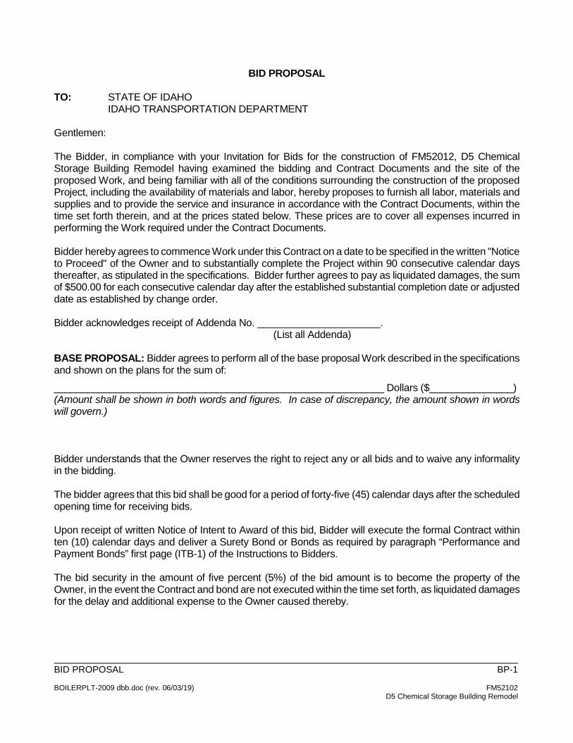
BID PROPOSAL TO: STATE OF IDAHO IDAHO TRANSPORTATION DEPARTMENT Gentlemen: The Bidder, in compliance with your Invitation for Bids for the construction of FM52012, D5 Chemical Storage Building Remodel having examined the bidding and Contract Documents and the site of the proposed Work, and being familiar with all of the conditions surrounding the construction of the proposed Project, including the availability of materials and labor, hereby proposes to furnish all labor, materials and supplies and to provide the service and insurance in accordance with the Contract Documents, within the time set forth therein, and at the prices stated below. These prices are to cover all expenses incurred in performing the Work required under the Contract Documents. Bidder hereby agrees to commence Work under this Contract on a date to be specified in the written "Notice to Proceed" of the Owner and to substantially complete the Project within 90 consecutive calendar days thereafter, as stipulated in the specifications. Bidder further agrees to pay as liquidated damages, the sum of $500.00 for each consecutive calendar day after the established substantial completion date or adjusted date as established by change order. Bidder acknowledges receipt of Addenda No. ______________________. (List all Addenda) BASE PROPOSAL: Bidder agrees to perform all of the base proposal Work described in the specifications and shown on the plans for the sum of: ___________________________________________________________ Dollars ($_______________) (Amount shall be shown in both words and figures. In case of discrepancy, the amount shown in words will govern.) Bidder understands that the Owner reserves the right to reject any or all bids and to waive any informality in the bidding. The bidder agrees that this bid shall be good for a period of forty-five (45) calendar days after the scheduled opening time for receiving bids. Upon receipt of written Notice of Intent to Award of this bid, Bidder will execute the formal Contract within ten (10) calendar days and deliver a Surety Bond or Bonds as required by paragraph “Performance and Payment Bonds” first page (ITB-1) of the Instructions to Bidders. The bid security in the amount of five percent (5%) of the bid amount is to become the property of the Owner, in the event the Contract and bond are not executed within the time set forth, as liquidated damages for the delay and additional expense to the Owner caused thereby.
BID PROPOSAL BP-2 BOILERPLT-2009 dbb.doc (rev. 06/03/19) FM52102 D5 Chemical Storage Building Remodel
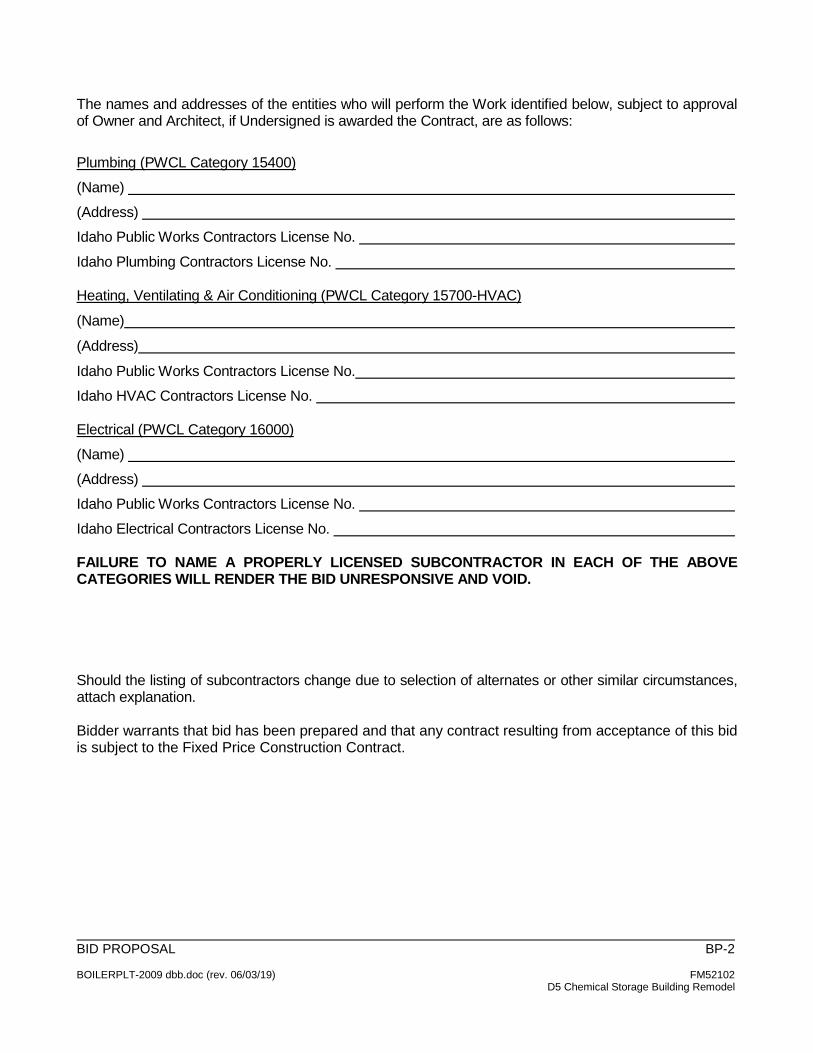
The names and addresses of the entities who will perform the Work identified below, subject to approval of Owner and Architect, if Undersigned is awarded the Contract, are as follows: Plumbing (PWCL Category 15400) (Name) (Address) Idaho Public Works Contractors License No. Idaho Plumbing Contractors License No. Heating, Ventilating & Air Conditioning (PWCL Category 15700-HVAC)
(Name)
(Address)
Idaho Public Works Contractors License No. Idaho HVAC Contractors License No. Electrical (PWCL Category 16000) (Name) (Address) Idaho Public Works Contractors License No. Idaho Electrical Contractors License No. FAILURE TO NAME A PROPERLY LICENSED SUBCONTRACTOR IN EACH OF THE ABOVE CATEGORIES WILL RENDER THE BID UNRESPONSIVE AND VOID. Should the listing of subcontractors change due to selection of alternates or other similar circumstances, attach explanation. Bidder warrants that bid has been prepared and that any contract resulting from acceptance of this bid is subject to the Fixed Price Construction Contract.

BID PROPOSAL BP-3 BOILERPLT-2009 dbb.doc (rev. 06/03/19) FM52102 D5 Chemical Storage Building Remodel
The undersigned notifies that it is of this date duly licensed as an Idaho Public Works Contractor and further that it possesses Idaho Public Works Contractor's License No. __________________________, or that it and its subcontractors shall have secured a Public Works Contractor’s License at or prior to award and execution of the Contract for construction and is domiciled in the State of _______________________. Dated this ________ day of_____________,_______. (date) (month) (year) Respectfully submitted by:
(Contractor’s Name- Typed) SEAL (Seal - if bid is by a corporation) (Street or PO Address) (City, State and zip code)
(Authorized Signature) (Title) (Telephone Number) (FAX Number) (Email Address) Have you remembered to include bid security (bid bond or a certified or cashier’s check), Contractor’s Affidavit Concerning Alcohol and Drug-Free Workplace and a signed copy of the Bidder’s Acknowledgment Statement with your bid? Execute and Submit with Bid
BID PROPOSAL BP-4 BOILERPLT-2009 dbb.doc (rev. 06/03/19) FM52102 D5 Chemical Storage Building Remodel
CONTRACTOR’S AFFIDAVIT CONCERNING ALCOHOL AND DRUG-FREE WORKPLACE
STATE OF COUNTY OF Pursuant to the Section 72-1717, Idaho Code, I, the undersigned, being duly sworn, depose and certify that _____________________________________ is in compliance with the provisions of Section 72-1717, Idaho Code; that _______________________________________ provides a drug-free workplace program that complies with the provisions of Title 72, Chapter 17, Idaho Code, and will maintain such program throughout the life of a state construction contract; and that ___________________________________ shall subcontract Work only to subcontractors meeting the requirements of Section 72-1717(1)(a), Idaho Code. Name of Contractor Address City and State By: (Signature) Subscribed and sworn to before me this ___________________ day of _________________, . NOTARY PUBLIC Residing at: Commission expires: FAILURE TO EXECUTE THIS AFFIDAVIT AND SUBMIT IT ALONG WITH YOUR BID SHALL MAKE YOUR BID NON-RESPONSIVE. Execute and Submit with Bid
BID PROPOSAL BP-5 BOILERPLT-2009 dbb.doc (rev. 06/03/19) FM52102 D5 Chemical Storage Building Remodel
BIDDER’S ACKNOWLEDGMENT STATEMENT
NOTE: THE INFORMATION CONTAINED HEREIN IS A SUMMARY OF VITAL CONTRACT PROVISIONS AND DOES NOT CHANGE THE CONTRACT DOCUMENTS THAT WILL GOVERN THIS PROJECT. Project number. FM52102, D5 Chemical Storage Building Remodel
By submitting a bid for this Project, the undersigned bidder agrees that, if awarded the Contract for construction, Contractor will conform to all conditions and requirements of the Contract, including but not limited to: • Contractor agrees to comply with conditions pertaining to Sections 44-1001 and 44-1002, Idaho
Code, requiring the employment of ninety-five percent (95%) bona fide Idaho residents and providing for a preference in the employment of bona fide Idaho residents and regarding the employment of persons not authorized to work in the United States.
• Contractor will substantially complete the Work within the time stated in the Contract Documents,
or as modified by Change Order(s). • If the Contractor fails to substantially complete the Project within the time stated in the Contract
Documents, or as modified by Change Order, the Contractor agrees that the Owner may deduct from the Contract amount liquidated damages in the amount per calendar day, indicated in the Contract Documents, times the number of calendar days until the Project is Substantially Complete, as defined in the Contract Documents and as determined by the Design Professional.
• The Contractor agrees that the amount allowed for overhead and profit on any Change Order is limited
to the amounts indicated in subparagraph 16.3.11 of the Fixed Price Construction Contract between Owner and Contractor. 1. For total changes the amount allowed for overhead, profit, bonds and insurance for the
Contractor and all subcontractors of any tier combined shall not exceed fifteen percent (15%) of direct costs; or
2. The Contractor will determine the amount of overhead and profit to be apportioned between the
Contractor and its subcontractor of allowable amounts of overhead, profit, bonds and insurance.
• The Contractor agrees that Change Orders are governed by the Fixed Price Construction Contract between Owner and Contractor General Conditions of the Contract for Construction including as follows: 1. By the execution of a Change Order, the Contractor agrees and acknowledges that it has had
sufficient time and opportunity to examine the change in Work which is the subject of the Change Order and that it has undertaken all reasonable efforts to discover and disclose any concealed or unknown conditions which may, to any extent, affect the Contractor’s ability to perform in accordance with the Change Order. Aside from those matters specifically set forth in the Change Order, the Owner shall not be obligated to make any adjustments to either the Contract Sum or Contract Time by reason of any conditions affecting the change in Work addressed by the
BID PROPOSAL BP-6 BOILERPLT-2009 dbb.doc (rev. 06/03/19) FM52102 D5 Chemical Storage Building Remodel
Change Order that could have reasonably been discovered or disclosed by the Contractor’s examination.
2. Any Change Order fully executed by the Owner, Contractor and Design Professional, including but not limited to, a Change Order arising by reason of the parties’ mutual agreement or by mediation, shall constitute a final and full settlement of all matters relating to or affected by the change in the Work, including but not limited to, all direct and consequential costs associated with such change and any and all adjustments to the Contract Price and Contract Time. In the event a Change Order increases the Contract Price, the Contractor shall include the Work covered by such Change Order in the Application for Payment as if such Work was originally part of the Project and Contract Documents.
FAILURE TO EXECUTE THIS ACKNOWLEDGMENT MAY MAKE YOUR BID NON-RESPONSIVE. I, _________________________________________________, being duly authorized to bind the (type or print name of individual) bidder, , does hereby certify that I have fully read (type or print name of company) and understand this document and that it highlights certain parts of the Contract that will be entered between the parties and that will govern this Project. Authorized Signature: _________________________________
Title: _______________________________________________
Date: _______________________________________________ END OF BIDDER’S ACKNOWLEDGMENT STATEMENT

BID PROPOSAL FPCC-1 BOILERPLT-2009 dbb.doc (rev. 06/03/19) FM52102 D5 Chemical Storage Building Remodel
IDAHO TRANSPORTATION DEPARTMENT FIXED PRICE CONSTRUCTION CONTRACT
BETWEEN OWNER AND CONTRACTOR
ITD PROJECT NO. FM52102 D5 Chemical Storage Building Remodel
Idaho Transportation Department 5151 South 5th Ave.
Pocatello, Idaho 83204
BID PROPOSAL FPCC-1 BOILERPLT-2009 dbb.doc (rev. 06/03/19) FM52102 D5 Chemical Storage Building Remodel
TABLE OF CONTENTS
ARTICLE 1 CONTRACT DOCUMENTS 2 REPRESENTATIONS AND WARRANTIES OF THE CONTRACTOR 3 INTENT AND INTERPRETATION
4 OWNERSHIP OF DOCUMENTS 5 CONTRACTOR'S PERFORMANCE 6 TIME FOR CONTRACTOR'S PERFORMANCE 7 FIXED PRICE AND CONTRACT PAYMENTS 8 INFORMATION AND MATERIAL SUPPLIED BY THE OWNER 9 STOP WORK ORDER 10 DUTIES, OBLIGATIONS AND RESPONSIBILITIES OF THE CONTRACTOR 11 INDEMNITY 12 THE DESIGN PROFESSIONAL 13 CLAIMS 14 RESOLUTION OF CLAIMS 15 SUBCONTRACTORS 16 CHANGES IN THE WORK 17 DISCOVERING AND CORRECTING DEFECTIVE OR INCOMPLETE WORK 18 TERMINATION BY THE CONTRACTOR 19 OWNER'S RIGHT TO SUSPEND CONTRACTOR'S PERFORMANCE 20 TERMINATION BY THE OWNER 21 CONTRACTOR'S LIABILITY INSURANCE 22 OWNER'S LIABILITY INSURANCE 23 PROPERTY INSURANCE 24 PERFORMANCE AND PAYMENT BONDS 25 PROJECT RECORDS 26 MISCELLANEOUS PROVISIONS 27 EQUAL OPPORTUNITY 28 SUCCESSORS AND ASSIGNS 29 SEVERABILITY 30 MEDIATION 31 WAIVER OF CONSEQUENTIAL DAMAGES
BID PROPOSAL FPCC-1 BOILERPLT-2009 dbb.doc (rev. 06/03/19) FM52102 D5 Chemical Storage Building Remodel
EXHIBITS A PROJECT IDENTIFICATION, ADDENDA, CONTRACT AMOUNT, CONTRACT TIME,
ACCEPTED ALTERNATES, LIQUIDATED DAMAGES AND SPECIAL CONDITIONS (IF ANY)
B ADDRESSES AND REPRESENTATIVES (INCLUDING LIMITATIONS) C LIST OF DRAWINGS AND SPECIFICATIONS D CONTRACTOR’S AFFIDAVIT CONCERNING TAXES E NAMED SUBCONTRACTORS F NOTICE TO PROCEED G REQUEST FOR TAX RELEASE H RELEASE OF CLAIMS J CONDITIONS PRECEDENT TO FINAL PAYMENT K TRAINING CONFIRMATION SIGN IN SHEET L PROJECT FINALIZATION AND START-UP

BID PROPOSAL FPCC-1 BOILERPLT-2009 dbb.doc (rev. 06/03/19) FM52102 D5 Chemical Storage Building Remodel
FIXED PRICE CONSTRUCTION CONTRACT BETWEEN OWNER AND CONTRACTOR
THIS FIXED PRICE CONSTRUCTION CONTRACT BETWEEN OWNER AND CONTRACTOR (the “Contract”) is by and between the State of Idaho, Idaho Transportation Department (“ITD” or the "Owner") and (insert name of contractor) (the "Contractor") and is for the construction of the project (the “Project”) identified as ITD Project No. FM52102 as more fully described in Exhibit A, and incorporated herein by reference. This Contract shall be effective on _______ (day) of ________ (month), 2020 (year), when executed by both parties. In consideration of the mutual promises, covenants, and agreements stated herein, and for other good and valuable consideration, the sufficiency of which is hereby acknowledged, the Owner and the Contractor agree:
ARTICLE 1 CONTRACT DOCUMENTS
1.1 The Contract Documents consist of this Contract, the drawings and specifications for the Project (the “Drawings and Specifications”) identified in Exhibit C and any Addenda thereto issued prior to execution of this Contract, written amendments signed by both the Owner and the Contractor, Change Orders signed by both the Owner and the Contractor, Construction Change Directives and any written orders by the Design Professional for minor changes in the Work (the “Contract Documents”). Documents not included or expressly contemplated in this Article 1 do not, and shall not, form any part of the Contract Documents. 1.2 The term “Work” means the construction and services required by the Contract Documents, whether completed or partially completed, and includes all other labor, materials, equipment and services provided or to be provided by the Contractor to fulfill the Contractor’s obligations.
ARTICLE 2 REPRESENTATIONS AND WARRANTIES OF THE CONTRACTOR
In order to induce the Owner to execute this Contract and recognizing that the Owner is relying thereon, the Contractor, by executing this Contract, makes the following express representations to the Owner: 2.1 The Contractor is fully qualified to act as the Contractor for the Project and has, and shall maintain, any and all licenses, permits or other authorizations necessary to act as the Contractor for, and to construct, the Project. 2.2 The Contractor has become familiar with the Project site and the local conditions under which the Project is to be constructed and operated particularly in correlation to the requirements of the Contract.
BID PROPOSAL FPCC-1 BOILERPLT-2009 dbb.doc (rev. 06/03/19) FM52102 D5 Chemical Storage Building Remodel
2.3 The Contractor has received, reviewed, compared, studied and carefully examined all of the documents which make up the Contract Documents, including the Drawings and Specifications, and any Addenda, and has found them in all respects to be complete, accurate, adequate, consistent, coordinated and sufficient for construction. Such review, comparison, study and examination shall be a warranty that the contractor believes that the documents are complete and the Project is buildable as described except as reported. 2.4 The Contractor warrants that the Contract Time is a reasonable period for performing the Work. 2.5 The Contractor warrants to the Owner and Design Professional that all labor furnished on this Project shall be competent to perform the tasks undertaken; materials and equipment furnished under the Contract will be new and of high quality unless otherwise required or permitted by the Contract Documents; that the Work will be complete, of high quality and free from defects not inherent in the quality required or permitted; and that the Work will strictly conform to the requirements of the Contract Documents. Any Work not strictly conforming to these requirements, including substitutions not properly approved and authorized, shall be considered defective. The Contractor’s warranty excludes remedy for damage or defect caused by abuse by Owner or its representatives, modifications not executed by the Contractor, improper or insufficient maintenance, improper operation, or normal wear and tear and normal usage. If required by the Owner, the Contractor shall furnish satisfactory evidence as to the kind and quality of materials and equipment. This warranty shall survive the completion of the Contract and final payment to the Contractor.
ARTICLE 3 INTENT AND INTERPRETATION
With respect to the intent and interpretation of this Contract, the Owner and the Contractor agree as follows: 3.1 This Contract constitutes the entire and exclusive agreement between the parties with reference to the Project, and supersedes any and all prior discussions, communications, representations, understandings, negotiations or agreements. This Contract also supersedes any bid documents. 3.2 The intent of the Contract is to include all items necessary for the proper execution and completion of the Project and anything that may be required, implied or inferred by the documents which make up this Contract, or any one or more of them, shall be provided by the Contractor for the Fixed Price Contract Amount. The Contract Documents are complementary, and what is required by one shall be as binding as if required by all. 3.3 Nothing contained in this Contract shall create, nor be interpreted to create, privity or any other relationship whatsoever between the Owner and any person or entity except the Contractor; provided, however, that the Design Professional is entitled to performance and enforcement of obligations under the Contract intended or necessary to facilitate its duties. Any reference to the Owner, the Contractor or the Design Professional shall be deemed to include authorized representatives.
BID PROPOSAL FPCC-1 BOILERPLT-2009 dbb.doc (rev. 06/03/19) FM52102 D5 Chemical Storage Building Remodel
3.4 When a word, term or phrase is used in this Contract, it shall be interpreted or construed first as defined herein; second, if not defined, according to its generally accepted meaning in the construction industry; and third, if there is no generally accepted meaning in the construction industry, according to its common and customary usage. 3.5 The words "include," "includes," or "including," as used in this Contract, shall be deemed to be followed by the phrase "without limitation." 3.6 The specification herein of any act, failure, refusal, omission, event, occurrence or condition as constituting a material breach of this Contract shall not imply that any other, non-specified act, failure, refusal, omission, event, occurrence or condition shall be deemed not to constitute a material breach of this Contract. 3.7 The Contractor shall have a continuing duty to read, examine, review, compare and contrast each of the documents which make up this Contract, shop drawings and other submittals, and shall give timely written notice to the Owner and the Design Professional of any conflict, ambiguity, error or omission which the Contractor may find with respect to these documents before proceeding with the affected Work. 3.8 The express or implied approval by the Owner or the Design Professional of any shop drawings or other submittals shall not relieve the Contractor of the continuing duties imposed hereby, nor shall any such approval be evidence of the Contractor's compliance with this Contract. The Owner has requested that the Design Professional prepare documents for the Project, including the Drawings and Specifications for the Project, which are accurate, adequate, consistent, coordinated and sufficient for construction. HOWEVER, THE OWNER MAKES NO REPRESENTATION OR WARRANTY OF ANY NATURE WHATSOEVER TO THE CONTRACTOR CONCERNING SUCH DOCUMENTS. The Contractor again hereby acknowledges and represents that it has received, reviewed and carefully examined such documents; has found them to be complete, accurate, adequate, consistent, coordinated and sufficient for construction; and that the Contractor has not, does not and will not rely upon any representations or warranties by the Owner concerning such documents, as no such representations or warranties have been or are hereby made. 3.9 In the event of any conflict among any of the documents which make up this Contract, the Design Professional shall interpret the documents, and the interpretation shall be binding on both the Owner and Contractor; provided, however, that this does not change the Owner’s right to make decisions regarding Claims in accordance with Article 13 and Article 14. If no interpretation is provided by the Design Professional, the most stringent requirement in the Contract Documents will apply.
ARTICLE 4 OWNERSHIP OF DOCUMENTS
4.1 Unless otherwise agreed by the Design Professional and its consultants, the party that prepared the drawings, specifications and other documents is the author of such with all copyright, common law, statutory and other reserved rights. The Contractor may retain one (1) record set of the Drawings and Specifications and other documents but shall not own or claim any copyright in them.
BID PROPOSAL FPCC-1 BOILERPLT-2009 dbb.doc (rev. 06/03/19) FM52102 D5 Chemical Storage Building Remodel
The Drawings and Specifications and other documents, and any copies, are to be used solely for this Project, and not on any other project, or additions to this Project outside this Contract, without written consent of the Owner, the Design Professional and the Design Professional’s consultants; provided, however, that copies may be made of applicable portions as necessary for completion of the Work. Such copies shall include any copyright notice on the Drawings and Specifications and other documents. Submission to or use by a regulatory body related to this Project is an acceptable use.
ARTICLE 5 CONTRACTOR'S PERFORMANCE
The Contractor shall perform all of the Work required, implied or reasonably inferable from this Contract, including the following: 5.1 Construction of the Project. 5.2 The furnishing of any required surety bonds and insurance. 5.3 The provision or furnishing, and prompt payment therefore, of labor, supervision, services, materials, supplies, equipment, fixtures, appliances, facilities, tools, transportation, storage, power, fuel, heat, light, cooling or other utilities required for construction and all necessary permits, including any required elevator permits, required for the construction of the Project. Construction projects for the State of Idaho require a building permit issued by the Division of Building Safety. 5.4 The creation and submission of a detailed and comprehensive set of marked up blue or black-lined record drawings. Said record drawings shall be submitted to and approved by the Design Professional as a condition precedent to final payment to the Contractor.
ARTICLE 6 TIME FOR CONTRACTOR'S PERFORMANCE
6.1 The Contractor shall commence the performance of this Contract in accordance with the "Notice to Proceed" (Exhibit F) issued by the Owner and shall diligently continue its performance to and until final completion of the Project. The Contractor shall accomplish Substantial Completion of the Project on or before the time indicated in Exhibit A. The period of time, including any adjustments made under this Contract, for the Contractor to reach Substantial Completion is the “Contract Time.” 6.2 The Contractor may be assessed by and be responsible to the Owner for the amount indicated in Exhibit A per day for each and every calendar day of unexcused delay in achieving Substantial Completion beyond the date set forth for Substantial Completion. Any sums owed hereunder by the Contractor shall be payable not as a penalty but as liquidated damages, representing an estimate of delay damages likely to be sustained by the Owner estimated at the time of this Contract. When the Owner reasonably believes that Substantial Completion will be inexcusably delayed, the Owner shall be entitled, but not required, to withhold from any
BID PROPOSAL FPCC-1 BOILERPLT-2009 dbb.doc (rev. 06/03/19) FM52102 D5 Chemical Storage Building Remodel
amounts otherwise due the Contractor an amount then believed by the Owner to be adequate to recover liquidated damages applicable to such delays. If and when the Contractor overcomes the delay in achieving Substantial Completion, or any part thereof, for which the Owner has withheld payment, the Owner shall promptly release to the Contractor those funds withheld, but no longer applicable, as liquidated damages. The Owner’s right to liquidated damages is not, and shall not be deemed to be, an exclusive remedy for delay and the Owner shall retain all remedies at law or in equity for delay or other breach. 6.3 The term "Substantial Completion," as used herein, shall mean that point at which, as certified in writing by the Design Professional, or if there is no Design Professional, as certified by the Owner, the entire Project is at a level of completion in strict compliance with the Contract Documents, such that the Owner or its designee can enjoy beneficial use or occupancy and can use or operate it in all respects for its intended purpose. If, in the reasonable determination of the Owner, receipt of operation and maintenance manuals or completion of training is necessary for such beneficial use or occupancy, then there shall be no Substantial Completion until such manuals are provided or such training is completed. Partial use or occupancy of the Project shall not result in the Project being deemed substantially complete, or accepted as substantially complete, and such partial use or occupancy shall not be evidence of Substantial Completion. The Project shall not be deemed accepted until it is finally complete. 6.4 Any request by the Contractor for an extension of the Contract Time must be made in accordance with, and is subject to, Article 13 and Article 14 related to Claims. 6.5 The Owner shall have no liability of any kind to the Contractor if a schedule or other document submitted by the Contractor shows an intention to complete the Work prior to the scheduled completion date and for any reason other than Owner caused delay, the Contractor is not able to achieve such early completion.
ARTICLE 7 FIXED PRICE AND CONTRACT PAYMENTS
7.1 The Owner shall pay, and the Contractor shall accept, as full and complete payment for the Contractor's timely performance of its obligations hereunder, the Fixed Price Contract Amount indicated in Exhibit A. The Fixed Price Contract Amount shall not be modified except as provided in this Contract. 7.2 Prior to approval of the contract, the Contractor shall prepare and present to the Owner and the Design Professional the Contractor's Schedule of Values apportioning the Fixed Price Contract Amount among the different elements of the Project for purposes of periodic and final payment. The Contractor's Schedule of Values shall be presented in the Owner’s web-based construction management software. The Contractor shall not imbalance it’s Schedule of Values nor artificially inflate any element thereof. The violation of this provision by the Contractor shall constitute a material breach of this Contract. The Contractor's Schedule of Values will be utilized for the Contractor's requests for payment but shall only be so utilized after it has been approved in writing by the Design Professional. 7.3 The Owner shall pay the Fixed Price Contract Amount to the Contractor in accordance with the procedures set forth in this Article. The Contractor shall submit a Contractor’s Request

BID PROPOSAL FPCC-1 BOILERPLT-2009 dbb.doc (rev. 06/03/19) FM52102 D5 Chemical Storage Building Remodel
for Payment, on or before the day of each month indicated in Exhibit A or otherwise agreed to, after commencement of performance, but no more frequently than once monthly. Said payment request shall be on made in the Owner’s web-based construction management software, and shall include whatever supporting information as may be required by the Design Professional, the Owner or both. Therein, the Contractor may request payment for one hundred percent (100%) of the Work satisfactorily completed to the date of the Contractor’s Request for Payment, less five percent (5%) retainage, based on the Fixed Price Contract Amount allocated on the Schedule of Values. The Contractor’s Request for Payment may include only: properly provided labor, materials or equipment properly incorporated into the Project, and time and materials or equipment necessary for the Project or that will be incorporated into the Project and are properly stored at the Project site (or elsewhere if off-site storage is approved in writing by the Owner). The Contractor’s Request for Payment must exclude the total amount of previous payments received from the Owner. Any payment on account of stored materials or equipment will be subject to the Contractor providing written proof that the Owner has title to such materials or equipment and that they are fully insured against loss or damage. Each such Contractor’s Request for Payment shall be signed by the Contractor and its submission shall constitute the Contractor's affirmative representation that the quantity of Work has reached the level for which payment is requested; that the Work has been properly installed or performed in strict compliance with the Contract; that all Work for which the Owner has previously paid is free and clear of any lien, claim or other encumbrance of any person whatsoever; and that the Contractor knows of no reason why payment should not be made as requested. As a condition precedent to payment, the Contractor shall, if required by the Owner, furnish to the Owner properly executed waivers or releases, in a form acceptable to the Owner, from all subcontractors, materialmen, suppliers or others having any claims or alleged claims, wherein said subcontractors, materialmen, suppliers or others shall acknowledge receipt of all sums due pursuant to all prior Contractor’s Requests for Payment, and waive and relinquish any rights or other claims relating to the Project or Project site. The submission by the Contractor of the Contractor’s Request for Payment also constitutes the Contractor’s affirmative representation that, upon payment of the Contractor’s Request for Payment submitted, title to all Work included in such payment shall be vested in the Owner. Thereafter, the Design Professional shall review the Contractor’s Request for Payment and may also review the Work at the Project site or elsewhere to determine whether the quantity and quality of the Work are as represented in the Contractor’s Request for Payment and as required by this Contract. The Design Professional shall approve in writing the amount which, in the opinion of the Design Professional, is properly owing to the Contractor and such approval is required before the Owner shall have any payment obligation. The Design Professional may withhold such approval, in whole or in part, as necessary to protect the Owner if it reasonably believes that the quantity or quality of the Work is not as represented in the Contractor’s Request for Payment or is not in strict conformance to the Contract Documents. 7.4 The Owner shall make payment to the Contractor no more than twenty-one (21) days following receipt by the Owner of the Design Professional's written approval of each Contractor’s Request for Payment. The amount of each such payment shall be the amount approved for payment by the Design Professional less such amounts, if any, otherwise owing by the Contractor to the Owner or which the Owner shall have the right to withhold as authorized by this Contract. The Design Professional's approval of the Contractor's Request for Payment shall
BID PROPOSAL FPCC-1 BOILERPLT-2009 dbb.doc (rev. 06/03/19) FM52102 D5 Chemical Storage Building Remodel
not preclude the Owner from the exercise of any of its rights it may have in this Contract, at law or in equity, as set forth in Paragraph 7.8 hereinafter. 7.5 Off-site storage will not be approved at locations more than thirty (30) miles from the Project site or outside the State of Idaho and any payment for any off-site storage is subject to the following:
.1 The Contractor must provide at least thirty (30) days’ advance written notice of its request to store off-site. Such notice must include a description of the type, quantities, locations and values of materials involved for the next billing cycle. All invoices must indicate the type, quantities and value of materials or equipment for which payment is requested;
.2 All materials stored off-site must be segregated and clearly marked with the DPW Project number and as being the “Property of the State of Idaho;”
.3 The Design Professional and/or the Owner’s Field Representative must have unrestricted access to the stored materials during all business hours and may physically inventory all invoiced materials and equipment and may physically inspect the storage conditions;
.4 The Contractor must provide written Consent of Surety to off-site storage of materials and equipment and to payment for such materials and equipment prior to incorporation in the Work. Consent must be from the Surety. Consent of local broker or agent is not acceptable;
.5 The Contractor must maintain and must provide to the Design Professional, upon request, a current log of stored materials and equipment, which reflects when materials and equipment are used or added; and
.6 The Contractor must obtain and maintain all risk property insurance at replacement cost, with the State of Idaho listed as loss payee on all materials and equipment stored off-site and in transit.
7.6 When payment is received from the Owner, the Contractor shall immediately pay all subcontractors, materialmen, laborer and suppliers the amounts they are due for the Work covered by such payment. The Contractor shall not withhold from a subcontractor or supplier more than the percentage withheld from a payment certificate for the subcontractor’s or supplier’s portion of the Work. In the event the Owner becomes informed that the Contractor has not paid a subcontractor, materialmen, laborer or supplier as provided herein, the Owner shall have the right, but not the duty, to issue future checks and payment to the Contractor of amounts otherwise due hereunder naming the Contractor and any such subcontractor, materialmen, laborer or supplier as joint payees. Such joint check procedure, if employed by the Owner, shall create no rights in favor of any person or entity beyond the right of the named payees to payment of the check and shall not be deemed to commit the Owner to repeat the procedure in the future. 7.7 Payment to the Contractor, utilization of the Project for any purpose by the Owner, or any other act or omission by the Owner shall not be interpreted or construed as an acceptance of any Work of the Contractor not strictly in compliance with this Contract.
BID PROPOSAL FPCC-1 BOILERPLT-2009 dbb.doc (rev. 06/03/19) FM52102 D5 Chemical Storage Building Remodel
7.8 The Owner shall have and be entitled to the right to refuse to make any payment, including by reducing payment under any Contractor’s Request for Payment, and, if necessary, may demand the return of a portion or all of an amount previously paid to the Contractor for reasons that include the following:
.1 The quality of the Contractor's work, in whole or part, is not in strict accordance with the requirements of this Contract or identified defective work, including punch list work, is not remedied as required by the Contract Documents;
.2 The quantity of the Contractor's work, in whole or in part, is not as represented in the Contractor's Request for Payment or otherwise;
.3 The Contractor's rate of progress is such that, in the Owner's opinion, Substantial Completion or final completion, or both, may be inexcusably delayed or that the Owner will incur additional costs or expense related to repeated Substantial Completion or final completion inspections through no fault of the Owner;
.4 The Owner reasonably believes that the Contractor has failed to use Contract funds, previously paid the Contractor by the Owner, to pay Contractor's project-related obligations, including subcontractors, laborers and material and equipment suppliers;
.5 There are claims made or it seems reasonably likely that claims will be made, against the Owner;
.6 The Contractor has caused a loss or damage to the Owner, the Design Professional or another contractor;
.7 The Owner reasonably believes that the Project cannot be completed for the unpaid balance of the Fixed Price Contract Amount or the Owner reasonably believes that the Project cannot be completed within the Contract Time and that the unpaid balance of the Fixed Price Contract Amount would be inadequate to cover the cost of actual or liquidated damages for the anticipated delay;
.8 The Contractor fails or refuses to perform any of its obligations to the Owner; or
.9 The Contractor fails to pay taxes as required by Title 63, Chapter 15, Idaho Code.
In the event that the Owner makes written demand upon the Contractor for amounts previously paid by the Owner as contemplated in Paragraph 7.8, the Contractor shall promptly comply with such demand. 7.9 If the Owner, without cause, fails to pay the Contractor any amounts due and payable thirty (30) days after those amounts are due pursuant to Paragraph 7.4, the Contractor shall have the right to cease the Work until receipt of proper payment. Contractor must first provide written notice to the Owner of the Contractor’s intent to cease the Work ten (10) days prior to stopping the Work under this Paragraph. If any amounts remain unpaid after fifty-one (51) days after the Design Professional approves the Contractor’s Request for Payment under Paragraph 7.4, interest at the rate of four percent (4%) per annum shall accrue on those unpaid amounts.
BID PROPOSAL FPCC-1 BOILERPLT-2009 dbb.doc (rev. 06/03/19) FM52102 D5 Chemical Storage Building Remodel
7.10 When Contractor considers Substantial Completion has been achieved, the Contractor shall notify the Owner and the Design Professional in writing and shall furnish to the Design Professional a listing of those matters yet to be finished. The Design Professional will thereupon conduct an inspection to confirm that the Work is, in fact, substantially complete. Upon its confirmation that the Contractor's work is substantially complete, the Design Professional will so notify the Owner and Contractor in writing and will therein set forth the date of Substantial Completion. The Owner and the Contractor must accept the date of Substantial Completion in writing. Guarantees and warranties required by this Contract shall commence on the date of Substantial Completion. At the Contractor’s Request for Payment following Substantial Completion, the Owner shall pay the Contractor an amount sufficient to increase total payments to the Contractor to ninety-five percent (95%) of the Fixed Price Contract Amount, less any liquidated damages, less the reasonable costs as determined by the Design Professional for completing all incomplete work, correcting and bringing into conformance all defective and nonconforming work, and handling any outstanding or potential claims. If the Design Professional determines that the Contractor has made or is making satisfactory progress on any uncompleted portions of the Work, the Owner may, at its discretion, release a portion of the retainage to the Contractor prior to the actual final completion of the conditions set forth in Paragraph 7.13. It is the intent of the parties that the Project will be accepted only in total (at Substantial Completion and final completion) and not in phases unless provided for in Exhibit A. Any acceptance other than in total shall require written agreement of Owner and Design Professional. 7.11 When Contractor considers the Project is at final completion, it shall notify the Owner and the Design Professional thereof in writing. Thereupon, the Design Professional will perform a final inspection of the Project. If the Design Professional confirms that the Project is complete in full accordance with the Contract Documents and that the Contractor has performed all of its obligations to the Owner, the Design Professional will furnish a final approval for payment to the Owner certifying to the Owner that the Project is complete and the Contractor is entitled to the remainder of the unpaid Fixed Price Contract Amount, less any amount withheld pursuant to this Contract. 7.12 If the Contractor fails to achieve final completion within a reasonable number of days as established by the Design Professional from the date of Substantial Completion, the Contractor may be assessed and be responsible to the Owner for fifty percent (50%) of the daily amount of liquidated damages as established pursuant to Paragraph 6.2 and Exhibit A, per day for each and every calendar day of unexcused delay in achieving final completion beyond the date established for final completion of the Work. Any sums due and payable hereunder by the Contractor shall be payable not as a penalty but as liquidated damages representing an estimate of delay damages likely to be sustained by the Owner, estimated at or before the time of executing this Contract. When the Owner reasonably believes that final completion will be inexcusably delayed, the Owner may withhold from any amounts otherwise due the Contractor an amount then believed by the Owner to be adequate to recover liquidated damages applicable to such delays. If and when the Contractor overcomes the delay in achieving final completion, or any part thereof, for which the Owner has withheld payment, the Owner shall promptly release to the Contractor those funds withheld, but no longer applicable, as liquidated damages. The Owner’s right to liquidated damages is not, and shall not be deemed to be, an exclusive remedy for delay and the Owner shall retain all remedies at law or in equity for delay or other breach.
BID PROPOSAL FPCC-1 BOILERPLT-2009 dbb.doc (rev. 06/03/19) FM52102 D5 Chemical Storage Building Remodel
7.13 As a condition precedent to final payment, the Contractor must furnish the Owner, in the form and manner required by Owner, and with a copy to the Design Professional of the following:
.1 An affidavit that all of the Contractor's obligations to subcontractors, laborers, equipment or material suppliers or other third parties in connection with the Project have been paid or otherwise satisfied;
.2 A release by the Contractor of all Claims it has or might have against the Owner or the Owner's property (DPW’s form, Exhibit H);
.3 Contractor’s Affidavit of Debts and Claims (AIA Document G706);
.4 Consent of Surety to final payment (AIA Document G707);
.5 Confirmation of all required training, product warranties, operating manuals, instruction manuals and other record documents, drawings and things customarily required of the Contractor; and
.6 A Public Works Contract Tax Release issued by the Idaho Tax Commission (See “Request for Tax Release” form, Exhibit G, to be submitted by Contractor to the Idaho Tax Commission).
7.14 The Owner shall, subject to its rights set forth in this Contract, make final payment of all sums due the Contractor within thirty (30) days of the Design Professional's execution of a final approval for payment and receipt of documentation required by Paragraph 7.13, whichever is received later.
ARTICLE 8 INFORMATION AND MATERIAL SUPPLIED BY THE OWNER
8.1 The ITD Facility Program Manager or his designee shall be the sole representative of the State of Idaho. The Design Professional shall have authority to bind Owner only as specifically set forth in this Contract. 8.2 The Owner will assign a Project Manager and a Field Representative to represent the Owner, identified in Exhibit B. The Owner’s Field Representative's duties, responsibilities and limitations of authority are in accordance with ITD’s policies and procedures. 8.3 The Owner shall furnish to the Contractor, prior to the execution of this Contract, any and all written and tangible material in its possession concerning conditions below ground at the site of the Project. Such written and tangible material is furnished to the Contractor only in order to make complete disclosure of such material as being in the possession of the Owner and for no other purpose. By furnishing such material, the Owner does not represent, warrant or guarantee its accuracy, either in whole in part, implicitly or explicitly. 8.4 The Owner will secure and pay for all required easements, the plan check fee required by the Division of Building Safety, conditional use permits and any other permits and fees specifically indicated in the Contract Documents to be secured and paid for by the Owner.
BID PROPOSAL FPCC-1 BOILERPLT-2009 dbb.doc (rev. 06/03/19) FM52102 D5 Chemical Storage Building Remodel
8.5 The Owner will provide the Contractor one (1) copy of this complete Contract and the number of sets of Drawings and Project Manuals (including Specifications) as indicated in Exhibit A. The Contractor may purchase additional copies, at its expense, from the Design Professional.
ARTICLE 9 STOP WORK ORDER
9.1 In the event the Contractor fails or refuses to perform the Work as required or fails or refuses to correct nonconforming Work, the Owner may instruct the Contractor to stop Work in whole or in part. Upon receipt of such instruction, the Contractor shall immediately stop as instructed by the Owner and shall not proceed further until the cause for the Owner's instructions has been corrected, no longer exists or the Owner instructs that the Work may resume. In the event the Owner issues such instructions to stop, and in the further event that the Contractor fails and refuses within seven (7) days of receipt of same to provide adequate assurance to the Owner that the cause of such instructions will be eliminated or corrected, then the Owner shall have the right, but not the obligation, to carry out the Work with its own forces or with the forces of another contractor, and the Contractor shall be fully responsible and liable for the costs of performing such Work by the Owner. Without limiting what else might constitute nonconforming Work, the existence of a gross safety violation or other situation or condition that creates, or could imminently create, a threat of serious harm to persons or property, shall constitute nonconforming Work and any order to stop the Work issued for such reason shall not be considered an interference with the Contractor’s performance of the Work or its means and methods. The rights set forth herein are in addition to, and without prejudice to, any other rights or remedies the Owner may have against the Contractor. 9.2 Any order to stop the Work issued pursuant to Paragraph 9.1 shall not be used to justify any Claim by the Contractor for additional time or money.
ARTICLE 10 DUTIES, OBLIGATIONS AND RESPONSIBILITIES OF THE CONTRACTOR
In addition to any and all other duties, obligations and responsibilities of the Contractor set forth in this Contract, the Contractor shall have and perform the following duties, obligations and responsibilities to the Owner: 10.1 The Contractor's continuing duties set forth in Paragraph 3.7 are by reference hereby incorporated in this Paragraph 10.1. The Contractor shall not perform Work without adequate plans and specifications or, as appropriate, approved shop drawings or other submittals. If the Contractor performs Work knowing or believing it involves an error, inconsistency or omission in the Contract without first providing written notice to the Design Professional and Owner, the Contractor shall be responsible for such Work and shall pay the cost of correcting same. 10.2 The Contractor shall take field measurements and verify field conditions and shall carefully compare such field measurements and conditions and other information known to the Contractor with the Contract Documents before commencing Work. Errors, inconsistencies or omissions discovered shall be reported to the Design Professional, the Owner and the Owner's Field Representative immediately. Such examination, review and comparison shall be a
BID PROPOSAL FPCC-1 BOILERPLT-2009 dbb.doc (rev. 06/03/19) FM52102 D5 Chemical Storage Building Remodel
warranty that the Contract Documents are complete and the Project is buildable as described except as reported. Reported errors, inconsistencies or omissions will constitute a request for an interpretation by the Design Professional and may constitute a claim pursuant to Article 13 hereof where appropriate. 10.3 The Contractor shall ensure that all Work shall strictly conform to the requirements of this Contract. 10.4 The Work shall be strictly supervised, the Contractor bearing full responsibility for any and all acts or omissions of those engaged in the Work on behalf of the Contractor. 10.5 All labor furnished on this Project shall be competent to perform the tasks undertaken; materials and equipment furnished under the Contract will be new and of high quality unless otherwise required or permitted by the Contract Documents; the Work will be complete, of high quality and free from defects not inherent in the quality required or permitted; and the Work will strictly conform to the requirements of the Contract Documents. Any Work not strictly conforming to these requirements, including substitutions not properly approved and authorized, shall be considered defective. 10.6 Except as provided in Paragraph 8.4, the Contractor shall secure or provide and pay for all licenses, permits required by the Idaho Division of Building Safety, governmental approvals and inspections, connections for outside services for the use of municipal or private property for storage of materials, parking, utility services, temporary obstructions, enclosures or opening and patching of streets, and for all other facilities and services necessary for proper execution and completion of the Project. 10.7 The Contractor shall comply with and give notices required by laws, ordinances, rules, regulations and lawful orders of public authorities bearing on performance of the Work. 10.8 The Contractor shall employ and maintain at the Project site only competent supervisory personnel. Key supervisory personnel assigned by the Contractor to this Project are as listed in Exhibit B. 10.9 The Contractor shall employ a competent superintendent and necessary assistants, as needed, to oversee execution of the Work. The superintendent shall be in attendance at the Project site during the progress of the Work. The superintendent and any project manager, if the Contractor utilizes a project manager, shall be reviewed and must be approved by the Design Professional and Owner, and neither shall be changed except with the consent of the Design Professional and Owner, unless the superintendent and/or project manager cease to be employed by the Contractor. Under this circumstance, any new superintendent or new project manager must be satisfactory to the Design Professional and Owner. Such approval shall not be unreasonably withheld. The superintendent and any project manager shall represent the Contractor and all communications given to the superintendent or project manager are deemed given to the Contractor. 10.10 So long as the individuals named above remain actively employed or retained by the Contractor, they shall perform the functions indicated next to their names unless the Owner agrees to the contrary in writing. In the event one or more individuals not listed in Paragraph
BID PROPOSAL FPCC-1 BOILERPLT-2009 dbb.doc (rev. 06/03/19) FM52102 D5 Chemical Storage Building Remodel
10.9 subsequently assumes one or more of those functions listed in Paragraph 10.9, the Contractor shall be bound by the provisions of this paragraph as though such individuals had been listed in Paragraph 10.9. 10.11 The Contractor shall provide to the Owner and the Design Professional a milestone schedule for completing the Work within the Contract Time. Such schedule shall be in a form specified in Division 1 of the Specifications and be acceptable to the Owner and to the Design Professional. The schedule must be submitted to and accepted by the Design Professional prior to the first request for payment unless required earlier by Division 1 of the Specifications. The Contractor's milestone schedule must be updated as required by the Design Professional and/or the Owner to reflect conditions encountered and shall apply to the total Project. The Contractor's revisions to the schedule shall not constitute a waiver of the requirement to complete the Project in the time allowed by the Contract, unless additional time for performance has been allowed pursuant to a Change Order. Any changes in milestone begin or end dates must be furnished to the Owner and the Design Professional. Strict compliance with the requirements of this Paragraph shall be a condition precedent to the payment to the Contractor and failure by the Contractor to strictly comply with said requirements shall constitute a material breach of this Contract. 10.12 Unless otherwise provided in the Construction Documents, on all projects where the Fixed Price Contract Amount is over $1,000,000, the Contractor shall schedule and perform the Work in accordance with a Critical Path Method (“CPM”) to indicate the rate of progress and practical order of the Project. The purpose of this scheduling requirement is to assure adequate planning, coordination and execution of the Work. The schedule shall indicate the dates for starting and completing major work activities, project events, major equipment, material and equipment submittals and delivery of major items. Project activities having critical time restraints on action, required by the Owner, shall be shown as scheduled milestones. The Contractor's schedule shall demonstrate the order, interdependence and sequence of activities. Critical paths shall be highlighted or distinguished. The schedule shall include all the dates specified in the Contract for Substantial Completion and final completion of the Work. The time limit set forth in the Contract for Substantial Completion and final completion must govern; the schedule must be adjusted to meet these dates. Schedule float shall belong to the Project. The Contractor shall submit to the Owner and Design Professional a CPM schedule within three (3) weeks after award of the Contract and maintain such schedule on a current basis in accordance with the Contract Documents. 10.13 Once a month, or at intervals as required by the Design Professional, the Contractor shall advise the Owner and the Design Professional of the status of the Work (in duplicate) on the current milestone schedule. If any project milestone dates are not met on schedule, the Contractor shall immediately advise the Owner and Design Professional in writing of the proposed action to bring the Work on schedule. The Contractor shall also submit a detailed short term schedule, as required by Division 1 of the Specifications, each month. This short term schedule shall include a description of current and anticipated problem areas, delaying factors and their impact, and explanation of corrective action taken or proposed. If the Work is behind schedule, the Contractor shall indicate what measures it will take to put the Work back on schedule.
BID PROPOSAL FPCC-1 BOILERPLT-2009 dbb.doc (rev. 06/03/19) FM52102 D5 Chemical Storage Building Remodel
10.14 If the Work is not progressing through no fault of the Owner or the Design Professional, as shown on the milestone schedule, as determined by the Design Professional, and the Owner and the Design Professional do not believe the Contractor's proposed action to bring the Work on schedule is adequate, then the Contractor shall be deemed in default under this Contract and the progress of the Work shall be deemed unsatisfactory. In such event, the Owner, at its discretion, may require the Contractor to work such additional time over regular hours, including Saturdays, Sundays and holidays, without additional cost to the Owner to bring the Work on schedule. 10.15 The Contractor shall keep an updated copy of the Drawings and Project Manual (including Specifications) and Addenda at the site. Additionally, the Contractor shall keep a current submittal schedule and a copy of approved shop drawings and other submittals. All of these items shall be available to the Owner and the Design Professional at all regular business hours. Upon final completion of the Work, all of these items must be updated by the Contractor and provided to the Design Professional and shall become the property of the Owner. 10.16 The Contractor shall carefully review and inspect for compliance with the Contract Documents, the shop drawings and other submittals (including product data and samples) required by the Contract Documents and shall submit to the Design Professional only submittals approved in accordance with this section. Such review and submittal shall be done promptly and in a sequence that will not delay its Work under this Contract or the activities of the Owner or of separate contractors. Shop drawings and other submittals from the Contractor do not constitute a part of the Contract. The Contractor shall not do any work requiring shop drawings or other submittals unless the Design Professional has verified compliance in writing. All Work requiring verified shop drawings or other submittals shall be done in strict compliance with such approved documents. However, verification of compliance by the Design Professional shall not be evidence that Work installed pursuant thereto conforms with the requirements of this Contract. The Design Professional shall have no duty to review submittals that are not Contractor approved, partial submittals or incomplete submittals. The Contractor shall maintain a submittal log which shall include, at a minimum, the date of each submittal, the date of any re-submittal, the date of any approval or rejection and the reason for any rejection. 10.17 The Contractor shall maintain the Project site in a reasonably clean condition during performance of the Work. Upon final completion, the Contractor shall thoroughly clean the Project site of all debris, trash and excess materials or equipment. 10.18 At all times relevant to this Contract, the Owner and the Design Professional shall have a right to enter the Project site and the Contractor shall allow the Owner and/or the Design Professional to review or inspect the work without formality or other procedure. 10.19 The presence or duties of the Design Professional’s or the Owner's personnel or representatives at the construction site, does not make any of them responsible for those duties that belong to the Contractor or other entities and does not relieve the Contractor or any other entities of their obligations, duties and responsibilities, including any obligation or requirement to have or to implement any health or safety plans or precautions. Except as provided in Paragraph 10.9, Design Professional's and Owner's personnel have no authority to exercise any control over any Contractor or other entities or their employees in connection with their work or any health or safety precautions and have no duty for inspecting, noting, observing, correcting
BID PROPOSAL FPCC-1 BOILERPLT-2009 dbb.doc (rev. 06/03/19) FM52102 D5 Chemical Storage Building Remodel
or reporting on health or safety deficiencies of the Contractor or other entities or any other persons at the site except their own personnel. The presence of Design Professional’s or Owner's personnel at a construction site is for the purpose of providing to Owner a greater degree of confidence that the completed Work will conform to the Contract Documents and that the integrity of the design concept as reflected in the Contract Documents has been implemented and preserved by the Contractor. For this Contract only, construction sites include places of manufacture for materials incorporated into the construction Work and Contractor includes manufacturers of materials incorporated into the construction Work.
ARTICLE 11 INDEMNITY
11.1 The Contractor shall defend, indemnify and hold harmless the Owner, Design Professional, [and the Idaho State Building Authority] and their employees, officers and agents harmless from any and all claims, liabilities, damages, losses, costs and expenses of every type whatsoever, including attorney fees and expenses, arising out of or resulting from the Contractor's work, acts or omissions under or related to the Contract Documents, to the extent caused by the Contractor, or anyone for whose acts the Contractor may be liable, regardless of whether such liability, claim, damage, loss, cost or expense is caused in part by the Owner. 11.2 The limits of any insurance of the Contractor shall not be, and shall not be deemed to be, a limitation of the Contractor’s defense and indemnity obligations contained in this Article. 11.3 In claims against any person or entity indemnified under this Article by an employee of the Contractor, a subcontractor, anyone directly or indirectly employed by them, or anyone for whose acts they may be liable, the indemnification obligation under this Article shall not be limited by a limitation on amount or type of damages, compensation or benefits payable by or for the Contractor or a subcontractor under workers' or workmen's compensation acts, disability benefit acts or other employee benefit acts.
ARTICLE 12 THE DESIGN PROFESSIONAL
The Design Professional for this Project is identified in Exhibit B, incorporated herein by reference, along with any authorized representatives and any limitations of responsibility. For the purpose of this Contract, the ”Design Professional” means the properly licensed architect, properly registered professional engineer or other professional licensed in the State of Idaho who prepared the Drawings and Specifications for this Project. If the employment of the Design Professional is terminated, the Owner may retain a replacement professional and the role of the replacement professional shall be the same as the role of the Design Professional. Unless otherwise directed by the Owner in writing, the Design Professional will perform those duties and discharge those responsibilities allocated to the Design Professional in this Contract. The duties, obligations and responsibilities of the Design Professional shall be for contract administration and include the following: 12.1 Unless otherwise directed by the Owner in writing, the Design Professional shall not act as the Owner's agent.
BID PROPOSAL FPCC-1 BOILERPLT-2009 dbb.doc (rev. 06/03/19) FM52102 D5 Chemical Storage Building Remodel
12.2 Unless otherwise directed by the Owner in writing, the Owner and the Contractor shall communicate with each other through the Design Professional. 12.3 When requested by the Owner or Contractor in writing, the Design Professional shall within seven (7) days render written interpretations necessary for the proper execution or progress of the Work or shall provide a written explanation as to why more time is needed and provide a date by which it will be provided. 12.4 The Design Professional shall draft proposed change authorization(s). 12.5 The Design Professional shall review and verify compliance or respond otherwise as necessary concerning shop drawings or other submittals received from the Contractor. 12.6 The Design Professional shall be authorized to refuse to accept Work that is defective or otherwise fails to comply with the requirements of this Contract. If the Design Professional deems it appropriate, the Design Professional may, with the Owner’s consent, require extra inspections or testing of the Work for compliance with the requirements of this Contract. 12.7 The Design Professional shall review the Contractor's Request for Payment and shall verify in writing those amounts which, in the opinion of the Design Professional, are properly owing to the Contractor as provided in this Contract. 12.8 The Design Professional shall, upon written request from the Contractor, perform Substantial Completion and final completion inspections contemplated by Article 6. 12.9 The Design Professional may require the Contractor to make changes which do not involve a change in the Fixed Price Contract Amount or in the Contract Time consistent with the intent of this Contract. Such changes shall be given to the Contractor in writing under signature of the Design Professional, with a copy to the Owner, and may be in the form of a supplemental instruction. 12.10 The Design Professional shall review and evaluate Claims and take other actions related to Claims in accordance with Articles 13 and 14. 12.11 The duties, obligations and responsibilities of the Contractor under this Contract shall in no manner whatsoever be changed, altered, discharged, released or satisfied by any duty, obligation or responsibility of the Design Professional. The Contractor is not a third-party beneficiary of any Contract by and between the Owner and the Design Professional. It is expressly acknowledged and agreed that the duties of the Contractor to the Owner are independent of, and are not diminished by, any duties of the Design Professional to the Owner.
ARTICLE 13 CLAIMS
13.1 For purposes of this Contract, a “Claim” means a demand by the Contractor to the Owner, or by the Owner to the Contractor, for a change in the Fixed Price Contract Amount, an extension of the Contract Time, an adjustment to or interpretation of the Contract terms, or other relief with respect to the terms of the Contract, which demand the Contractor or Owner asserts
BID PROPOSAL FPCC-1 BOILERPLT-2009 dbb.doc (rev. 06/03/19) FM52102 D5 Chemical Storage Building Remodel
is required or allowed under the Contract Documents and which the Contractor and the Owner have previously discussed and failed to agree upon. 13.2 For the Claim to be considered, it must meet the following requirements:
.1 The Claim must be in writing;
.2 The Claim by the Contractor must be signed by an authorized representative of the Contractor, and the Claim by the Owner must be signed by an authorized representative of the Owner;
.3 The Claim by the Contractor must be provided to the Owner and to the Design Professional and the Claim by the Owner must be provided to the Contractor and to the Design Professional;
.4 The Claim must be made no later than ten (10) days after the event or first appearance of the circumstance giving rise to the Claim;
.5 The Claim must describe in detail all known facts and circumstances that the Contractor or Owner asserts support the Claim;
.6 The Claim must refer to the provision(s) of the Contract Documents that the Contractor or Owner asserts support the Claim;
.7 The Contractor or Owner must provide all documentation or other information to substantiate the Claim; and
.8 The Contractor or Owner must continue its performance under this Contract pending the resolution of any Claim; provided, however, that the Contractor shall not perform any additional or changed work not otherwise authorized in accordance with the Contract Documents.
13.3 The failure by the Contractor to meet any of the requirements of Paragraph 13.2 shall constitute a complete waiver by the Contractor of any rights arising from or related to the Claim. Similarly, the failure by the Owner to meet any of the requirements of Paragraph 13.2 shall constitute a complete waiver by the Owner of any rights arising from or related to the Claim. 13.4 If the Claim is made based on concealed or unknown site conditions, the following shall apply in addition to all other provisions applicable to the Claim:
.1 The condition must have been previously concealed and unknown or of a type not ordinarily encountered in the general geographic location of the Project and must not have been reasonably susceptible to discovery; and
.2 The Contractor shall notify the Design Professional and the Owner of the condition and shall not disturb the condition until the Design Professional and Owner have observed it or have waived in writing the right to observe it.
13.5 If the Claim by the Contractor is for an increase in the Fixed Price Contract Amount, the following shall apply in addition to all other provisions applicable to the Claim:
BID PROPOSAL FPCC-1 BOILERPLT-2009 dbb.doc (rev. 06/03/19) FM52102 D5 Chemical Storage Building Remodel
.1 Any increase in the Fixed Price Contract Amount shall be strictly limited to the direct costs incurred by the Contractor and shall not include any other costs, indirect or other, including any costs for or related to lost productivity, profit, home office overhead and any other overhead, legal fees, claim preparation, any matter previously resolved by a change order, equipment costs, costs related to the services of a project manager unless the project manager was required full time by the Owner or the Contract Documents, any costs associated with the failure to complete the Work early or in advance of the date required by the Contract Documents, it being specifically agreed to by the parties that there is no intention to have the Eichleay or other similar formula applicable to this Contract nor shall this Contract be deemed to be subject to any such formula; and
.2 The Owner shall have no liability for, and the Fixed Price Contract Amount shall not be increased related to, any claims of third parties, including subcontractors, unless and until the liability of the Contractor for such has been established in a court of competent jurisdiction and any such liability of the Owner shall be limited in the same manner as described in subparagraph 13.5.1.
13.6 If the Claim by the Owner is for a change in the Fixed Price Contract Amount, all other applicable provisions to the Claim apply.
13.7 If the Claim by the Contractor is for an extension of the Contract Time, the following shall apply in addition to all other provisions applicable to the Claim:
.1 The Contractor has been delayed in its performance by an act or omission of the Owner and through no fault of the Contractor;
.2 The Contractor has been delayed in its performance by unusually severe weather that could not reasonably have been anticipated or by another event not within its reasonable control;
.3 At the time it occurs or during its occurrence, the delay will preclude completion of the Project in the time required by the Contract Documents; and
.4 Any extension of the Contract Time shall be the Contractor’s sole and exclusive remedy for any delay except a delay caused by the active interference of the Owner with the Contractor’s performance which active interference continues after written notice to the Owner. The Owner’s exercise of any of its rights or remedies under this Contract, including ordering changes in the Work, directing suspension, rescheduling or correction of the Work, do not constitute active interference.
13.8 If a Claim is made based on an error, inconsistency or omission in the Contract that was reasonably susceptible to discovery by the Contractor and was not reported in accordance with Paragraph 2.3, that Claim shall be denied.
BID PROPOSAL FPCC-1 BOILERPLT-2009 dbb.doc (rev. 06/03/19) FM52102 D5 Chemical Storage Building Remodel
ARTICLE 14 RESOLUTION OF CLAIMS
14.1 All Claims made in accordance with Article 13 shall be reviewed and evaluated by the Design Professional. If the Claim is not made in strict accordance with Article 13, it shall be rejected as waived. Any failure by the Design Professional to reject the Claim for failure to meet the requirements of Article 13 is not binding on the Owner and the Owner may reject the Claim for such failure. 14.2 No later than seven (7) days from receipt of the Claim by the Design Professional, it shall:
.1 Make a written request to the Contractor or Owner for more data to support the Claim;
.2 Attempt to facilitate resolution of the Claim through informal negotiations; or
.3 If the Claim is by the Contractor, make a written recommendation to the Owner, with a copy to the Contractor, that the Owner reject or approve all or part of the Claim and state the reasons for the Design Professional’s recommendation. If the Claim is by the Owner, make a written recommendation to the Contractor, with a copy to the Owner, that the Contractor reject or approve all or part of the Claim and state the reasons for the Design Professional’s recommendation.
14.3 If the Design Professional requests more data from the Contractor or the Owner under subparagraph 14.2.1, the Contractor or Owner shall respond no later than seven (7) days from receipt of such request, and provide additional data, provide a date certain by which additional data will be provided, or state that it will not provide additional data. Upon receipt of data, if any, in accordance with this section, the Design Professional will complete the evaluation of the Claim. Failure to respond at all or failure to provide data by the date specified in the response to the request shall result in the Claim being evaluated based on the information in the Design Professional’s possession. 14.4 In evaluating the Claim, the Design Professional may consult with the Contractor, the Owner or other persons with knowledge or expertise that may assist the Design Professional in its evaluation. 14.5 No later than fourteen (14) days after receipt by the Owner of the Design Professional’s recommendation regarding the Contractor’s Claim, the Owner shall, in writing, notify the Contractor and the Design Professional of its decision regarding the Claim. No later than fourteen (14) days after receipt by the Contractor of the Design Professional’s recommendation regarding the Owner’s Claim, the Contractor shall, in writing, notify the Owner and the Design Professional of its decision regarding the Claim. 14.6 The Owner’s decision regarding the Contractor’s Claim is binding on the Owner and the Contractor but is subject to mediation in accordance with this Contract, and the Contractor’s decision regarding the Owner’s Claim is binding on the Owner and the Contractor but is subject to mediation in accordance with this Contract.
BID PROPOSAL FPCC-1 BOILERPLT-2009 dbb.doc (rev. 06/03/19) FM52102 D5 Chemical Storage Building Remodel
ARTICLE 15 SUBCONTRACTORS
15.1 A document in the form of Exhibit E shall be completed and submitted upon execution of this Contract and those subcontractors named therein shall match those subcontractors named in the Contractor’s bid unless otherwise agreed to in writing by the Owner. Also upon execution of this Contract by the Contractor, the Contractor shall identify to the Owner and the Design Professional, in writing, those parties intended as subcontractors on the Project not otherwise named in Exhibit E. The Owner shall, in writing, state any objections the Owner may have to one or more of such subcontractors. The Contractor shall not enter into a subcontract with an intended subcontractor with reference to whom the Owner objects. All subcontracts shall afford the Contractor rights against the subcontractor which correspond to those rights afforded to the Owner against the Contractor herein, including those rights of Contract Termination as set forth in this Contract. All subcontractors shall, throughout the duration of this Contract, be properly licensed as Idaho Public Works Contractors. 15.2 The Contractor conditionally assigns each of its subcontracts related to the Project to the Owner. All subcontracts between the Contractor and the subcontractors shall obligate the subcontractor to such conditional assignment. Upon a Termination by the Owner for cause under Paragraph 20.1, the Owner may accept such conditional assignment by written notification to the applicable subcontractor and to the Contractor. Such acceptance is subject to the rights of the Surety, if any, relating to the Contract.
ARTICLE 16 CHANGES IN THE WORK
16.1 General
.1 Changes in the Work may be accomplished after execution of the Contract, and without invalidating the Contract, by Change Order, Construction Change Directive or order for a minor change in the Work, subject to the limitations stated in this Article and elsewhere in the Contract Documents; and
.2 Changes in the Work shall be performed under applicable provisions of the Contract Documents and the Contractor shall proceed promptly, unless otherwise provided in the Change Order, Construction Change Directive or order for a minor change in the Work.
16.2 Change Orders
.1 A “Change Order” is a written instrument prepared by the Design Professional and signed by the Owner, Contractor and Design Professional, stating their agreement upon: a change in the work, any adjustment in the Fixed Price Contract Amount and any adjustment in the Contract Time;
.2 Methods used in determining adjustments to the Fixed Price Contract Amount may include those listed in subparagraph 16.3.4;
BID PROPOSAL FPCC-1 BOILERPLT-2009 dbb.doc (rev. 06/03/19) FM52102 D5 Chemical Storage Building Remodel
.3 The amount allowed for overhead and profit on any Change Order is limited to the amounts indicated in subparagraph 16.3.11;
.4 Any Change Order prepared, including those arising by reason of the parties’ mutual agreement or by mediation, shall constitute a final and full settlement of all matters relating to or affected by the change in the Work, including all direct, indirect and consequential costs associated with such change and any and all adjustments to the Fixed Price Contract Amount and Contract Time. In the event a Change Order increases the Fixed Price Contract Amount, the Contractor shall include the Work covered by such Change Order in the Contractor’s Request for Payment as if such Work were originally part of the Project and Contract Documents; and
.5 By the execution of a Change Order, the Contractor agrees and acknowledges that it has had sufficient time and opportunity to examine the change in Work which is the subject of the Change Order and that it has undertaken all reasonable efforts to discover and disclose any concealed or unknown conditions which may to any extent affect the Contractor’s ability to perform in accordance with the Change Order. Aside from those matters specifically set forth in the Change Order, the Owner shall not be obligated to make any adjustments to either the Fixed Price Contract Amount or Contract Time by reason of any conditions affecting the change in Work addressed by the Change Order, which could have reasonably been discovered or disclosed by the Contractor’s examination.
16.3 Construction Change Directive (CCD)
.1 A “Construction Change Directive” is a written order prepared by the Design Professional and signed by the Owner and Design Professional directing a change in the Work prior to agreement on adjustment, if any, in the Fixed Price Contract Amount or Contract Time or both. The Owner may by Construction Change Directive, without invalidating the Contract, order changes in the Work within the general scope of the Contract, consisting of additions, deletions or other revisions, the Fixed Price Contract Amount and Contract Time being adjusted accordingly;
.2 A Construction Change Directive, within limitations, may also be used to incorporate minor changes in the Work agreed to by the Design Professional’s representative, the Owner’s Field Representative and the Contractor’s superintendent or project manager. The limits of these representatives’ authority with regard to Construction Change Directives shall be documented in writing by the Design Professional, Owner and Contractor;
.3 A Construction Change Directive shall be used in the absence of total agreement on the terms of a Change Order;
.4 If the Construction Change Directive provides for an adjustment to the Fixed Price Contract Amount, the adjustment shall be based on one (1) of the following methods:
.1 Mutual acceptance of a lump sum properly itemized and supported by sufficient substantiating data to permit evaluation;
BID PROPOSAL FPCC-1 BOILERPLT-2009 dbb.doc (rev. 06/03/19) FM52102 D5 Chemical Storage Building Remodel
.2 Unit prices stated in the Contract Documents or subsequently agreed upon;
.3 Cost to be determined in a manner agreed upon by the parties and a mutually acceptable fixed or percentage fee; or
.4 As provided in subparagraph 16.3.7;
.5 Upon receipt of a Construction Change Directive, the Contractor shall promptly proceed with the change in the Work involved and advise the Design Professional in writing within forty-eight (48) hours of the Contractor’s agreement or disagreement with the method, if any, provided in the Construction Change Directive for determining the proposed adjustment in the Fixed Price Contract Amount or Contract Time;
.6 A Construction Change Directive signed by the Contractor indicates the agreement of the Contractor therewith, including adjustment in Fixed Price Contract Amount and Contract Time or the method for determining them. Such agreement shall be effective immediately and shall be incorporated into a future Change Order;
.7 If the Contractor does not respond promptly or disagrees with the method for adjustments in the Fixed Price Contract Amount or Contract Time, the method and the adjustment shall be determined by the Design Professional on the basis of reasonable expenditures and savings of those performing the Work attributable to the change, including, in case of an increase in the Fixed Price Contract Amount, an allowance for overhead and profit in accordance with subparagraph 16.3.11. In such case of an increase in Fixed Price Contract Amount, and also under subparagraph 16.3.4, the Contractor shall keep and present, in such form as the Design Professional may prescribe, an itemized accounting together with appropriate supporting data. Unless otherwise provided in the Contract Documents, costs for the purposes of this subsection shall be limited to the following:
.1 Costs of labor, including social security, old age and unemployment insurance, fringe benefits required by agreement or custom and workers’ compensation insurance;
.2 Costs of materials, supplies and equipment, including cost of transportation, whether incorporated or consumed;
.3 Rental costs of machinery and equipment, exclusive of hand tools, whether rented from the Contractor or others;
.4 Costs of permit fees and sales, use or similar taxes related to the Work; and
.5 Additional costs of supervision and field office personnel directly attributable to the change;
.8 The amount of credit to be allowed by the Contractor to the Owner for a deletion or change which results in a net decrease in the Fixed Price Contract Amount shall be for the actual net cost of the decrease, confirmed by the Design Professional. When both additions and credits covering related Work or substitutions are involved in a

BID PROPOSAL FPCC-1 BOILERPLT-2009 dbb.doc (rev. 06/03/19) FM52102 D5 Chemical Storage Building Remodel
change, the allowance for overhead and profit shall be figured on the basis of net increase, if any, with respect to that change;
.9 Pending final determination of the total cost of a Construction Change Directive to the Owner, amounts not in dispute for such changes in the Work shall be included in the Contractor’s Request for Payment accompanied by a Change Order indicating the parties’ agreement with part or all of such costs;
.10 When the Owner and Contractor agree with the determination by the Design Professional concerning the adjustments in the Fixed Price Contract Amount and Contract Time, or otherwise reach agreement upon the adjustments, such agreement shall be effective immediately and shall be recorded by preparation and execution of an appropriate Change Order; and
.11 For purposes of subparagraphs 16.2.3 and 16.3.7, the allowance for combined overhead, profit, bonds and insurance shall be limited as follows, unless otherwise provided in the Contract Documents:
.1 For changes, the amount allowed for overhead, profit, bonds and insurance for the Contractor and all subcontractors of any tier combined shall not exceed fifteen percent (15%) of direct costs; or
.2 The Contractor will determine the apportionment between the Contractor and its subcontractors of allowable amounts of overhead, profit, bonds and insurance.
16.4 The Design Professional will have authority to order minor changes in the Work not involving adjustment in the Fixed Price Contract Amount or extension of the Contract Time and not inconsistent with the intent of the Contract Documents. Such changes shall be effected by written order and shall be binding on the Owner and Contractor. The Contractor shall carry out such written orders promptly.
ARTICLE 17 DISCOVERING AND CORRECTING DEFECTIVE OR INCOMPLETE WORK
17.1 If the Contractor covers, conceals or obscures its Work in violation of this Contract or in violation of a directive or request from the Owner or the Design Professional, such Work shall be uncovered and displayed for the Owner's or Design Professional's inspection upon request and shall be reworked at no cost in time or money to the Owner. 17.2 If any of the Work is covered, concealed or obscured in a manner not addressed by Paragraph 17.1, it shall, if directed by the Owner or the Design Professional, be uncovered and displayed for the Owner's or Design Professional's inspection. If the uncovered Work conforms strictly with this Contract, the costs incurred by the Contractor to uncover and subsequently replace such Work shall be borne by the Owner. Otherwise, such costs shall be borne by the Contractor. 17.3 The Contractor shall, at no cost in time or money to the Owner, promptly correct Work (fabricated, installed or completed) rejected by the Owner or by the Design Professional as defective or that fails to conform to this Contract whether discovered before or after Substantial
BID PROPOSAL FPCC-1 BOILERPLT-2009 dbb.doc (rev. 06/03/19) FM52102 D5 Chemical Storage Building Remodel
Completion. Additionally, the Contractor shall reimburse the Owner for all testing, inspections and other expenses incurred as a result thereof. 17.4 In addition to any other warranty obligations in this Contract, the Contractor shall be specifically obligated to correct, upon written direction from the Owner, any and all defective or nonconforming Work for a period of twelve (12) months following Substantial Completion. 17.5 The Owner may, but shall in no event be required to, choose to accept defective or nonconforming Work. In such event, the Fixed Price Contract Amount shall be reduced by the lesser of: (i) the reasonable costs of removing and correcting the defective or nonconforming Work; or (ii) the difference between the fair market value of the Project as constructed and the fair market value of the Project had it not been constructed in such a manner as to include defective or nonconforming Work. If the remaining portion of the unpaid Fixed Price Contract Amount, if any, is insufficient to compensate the Owner for the acceptance of defective or nonconforming Work, the Contractor shall, upon written demand from the Owner, pay the Owner such remaining compensation for accepting defective or nonconforming work.
ARTICLE 18 TERMINATION BY THE CONTRACTOR
18.1 The Contractor may terminate the Contract if the Work is stopped for a period of ninety (90) consecutive days through no act or fault of the Contractor or a subcontractor, sub-subcontractor or their agents or employees or any other persons or entities performing portions of the Work under direct or indirect contract with the Contractor, for any of the following reasons:
.1 Issuance of an order by a court or by another public authority having jurisdiction and authority which requires all Work to be stopped; or
.2 An act of government, such as a declaration of national emergency, which requires all Work to be stopped.
18.2 In such event, the Contractor shall be entitled to recover from the Owner as though the Owner had terminated the Contractor's performance under this Contract pursuant to Paragraph 20.3.
ARTICLE 19 OWNER'S RIGHT TO SUSPEND CONTRACTOR'S PERFORMANCE
19.1 The Owner may, at any time and without cause, order the Contractor, in writing, to suspend, delay or interrupt the Work in whole or in part for such period of time as the Owner may determine. If the Owner directs any such suspension, the Contractor must immediately comply with same. 19.2 In the event the Owner directs a suspension of performance under this Article, and such suspension is through no fault of the Contractor, the Fixed Price Contract Amount and Contract Time shall be adjusted for increases in the cost and time caused by such suspension, delay or interruption to cover the Contractor's reasonable costs, actually incurred and paid, of:
BID PROPOSAL FPCC-1 BOILERPLT-2009 dbb.doc (rev. 06/03/19) FM52102 D5 Chemical Storage Building Remodel
.1 Demobilization and remobilization, including such costs paid to subcontractors;
.2 Preserving and protecting Work in place;
.3 Storage of materials or equipment purchased for the Project, including insurance thereon; and
.4 Performing in a later, or during a longer, time frame than that provided by this Contract.
19.3 The adjustment of the Fixed Price Contract Amount shall include an amount for a reasonable profit. The adjustment of the Fixed Price Contract Amount shall not include any amount not otherwise allowed under this Contract, including any limitations applicable to Claims. The Contractor shall provide supporting documentation related to any increase upon request of the Owner. No adjustment shall be made to the extent:
.1 That performance is, was or would have been so suspended, delayed or interrupted by another cause for which the Contractor is responsible; or
.2 That an equitable adjustment is made or denied under another provision of the Contract.
ARTICLE 20 TERMINATION BY THE OWNER
The Owner may terminate this Contract in accordance with the following terms and conditions: 20.1 If the Contractor does not perform the Work, or any part thereof, in accordance with the Contract Documents, or in a timely manner; does not supply adequate labor, supervisory personnel, or proper equipment or materials; fails to pay subcontractors; fails to timely discharge its obligations for labor, equipment, and materials; proceeds to disobey applicable law; or otherwise breaches this Contract, then the Owner, in addition to any other rights it may have against the Contractor, may terminate the Contract and assume control of the Project site and of all materials and equipment at the site and may complete the Work. In such case, the Contractor shall not be paid further until the Work is complete. Upon such Termination, the Owner may, subject to any superior rights of the Surety, take possession of the site and of all materials, equipment, tools and construction equipment and machinery thereon owned by the Contractor; accept assignment of those subcontracts conditionally assigned under Paragraph 15.2; and finish the Work by whatever reasonable method the Owner may deem expedient. 20.2 When the Owner terminates the Contract for cause as provided in Paragraph 20.1, the Contractor shall not be entitled to receive further payment until the Work is finished and shall only be entitled to payment for Work satisfactorily performed by the Contractor in accordance with the Contract Documents. If the costs of finishing the Work, including compensation for the Design Professional’s services and expenses made necessary thereby, exceed the unpaid balance, the Contractor shall pay the difference to the Owner. This obligation for payment shall survive termination of the Contract. The Contractor shall also terminate outstanding orders and subcontracts. The Contractor shall settle the liabilities and claims arising out of the termination
BID PROPOSAL FPCC-1 BOILERPLT-2009 dbb.doc (rev. 06/03/19) FM52102 D5 Chemical Storage Building Remodel
of subcontracts and orders. In the event the employment of the Contractor is terminated by the Owner for cause pursuant to Paragraph 20.1 and it is subsequently determined by a court of competent jurisdiction that such termination was without cause, such termination shall thereupon be deemed a Termination under Paragraph 20.3 and the provisions of Paragraph 20.3 shall apply.
20.3 The Owner may, at any time and for any reason, terminate this Contract. The Owner shall give no less than seven (7) days’ written notice of such Termination to the Contractor specifying when termination becomes effective. The Contractor shall incur no further obligations in connection with the Work and the Contractor shall stop Work when such Termination becomes effective. The Contractor shall also terminate outstanding orders and subcontracts. The Contractor shall settle the liabilities and claims arising out of the termination of subcontracts and orders. The Owner may direct the Contractor to assign the Contractor's right, title and interest under termination orders or subcontracts to the Owner or its designee. The Contractor shall transfer title and deliver to the Owner such completed or partially completed Work and materials, equipment, parts, fixtures, information and Contract rights as the Contractor has. When terminated pursuant to this section, the following shall apply:
.1 The Contractor shall submit a Termination Claim to the Owner and the Design Professional specifying the amounts claimed due because of the Termination, together with costs, pricing or other supporting data required by the Owner or the Design Professional. Failure by the Contractor to file a Termination Claim within ninety (90) days from the effective date of termination shall be deemed a complete waiver by the Contractor of any right to any payment;
.2 Before or after receipt of the Termination Claim, the Owner and the Contractor may agree to the compensation, if any, due to the Contractor hereunder; and
.3 If the Contractor has filed the Termination Claim but the Contractor and the Owner do not agree on an amount due to the Contractor, the Owner shall pay the Contractor the following amounts:
.1 Unpaid Contract prices for labor, materials, equipment and other services provided or perfected prior to termination and acceptable to or accepted by the Owner;
.2 Reasonable costs incurred in preparing to perform the terminated portion of the Work, and in terminating the Contractor's performance, plus a fair and reasonable allowance for direct job-site overhead and profit related to such preparation (such profit shall not include anticipated profit or consequential damages); provided, however, that if it appears that the Contractor would have not profited or would have sustained a loss if the entire Contract would have been completed, no profit shall be allowed or included and the amount of compensation shall be reduced to reflect the anticipated loss, if any; and
.3 Reasonable costs of settling and paying claims arising out of the Termination of subcontracts or orders pursuant to this Paragraph 20.3.
20.4 Costs described in subparagraphs 20.3.3.2 or 20.3.3.3 above shall not include amounts paid in accordance with other provisions hereof. In no event shall the total sum to be paid the
BID PROPOSAL FPCC-1 BOILERPLT-2009 dbb.doc (rev. 06/03/19) FM52102 D5 Chemical Storage Building Remodel
Contractor under subparagraph 20.3.3 exceed the total Fixed Price Contract Amount, as properly adjusted, reduced by the amount of payments previously or otherwise made and by any other deductions permitted under this Contract and shall in no event include duplication of payment.
ARTICLE 21 CONTRACTOR'S LIABILITY INSURANCE
21.1 The Contractor, subcontractor and sub-subcontractor shall purchase and maintain in full force and effect from a company or companies lawfully authorized to do business in the State of Idaho such insurance as will protect the Contractor, subcontractor and sub-subcontractor from claims set forth below which may arise out of or result from the Contractor's or subcontractor’s operations under the Contract and for which the Contractor may be legally liable, whether such operations be by the Contractor or by a subcontractor or by anyone directly or indirectly employed by any of them or by anyone for whose acts any of them may be liable:
.1 Claims under workers' or workmen's compensation, disability benefits and other similar employee benefit acts which are applicable to the work to be performed;
.2 Claims for damages because of bodily injury, occupational sickness or disease or death of the Contractor's employees;
.3 Claims for damages because of bodily injury, sickness or disease or death of any person other than the Contractor's employees;
.4 Claims for damages insured by usual personal injury liability coverage which are sustained: (i) by a person as a result of an offense directly or indirectly related to employment of such person by the Contractor; or (ii) by another person;
.5 Claims for damages, other than to the Work itself, because of injury to or destruction of tangible property, including loss of use resulting there from;
.6 Claims for damages because of bodily injury, death of a person or property damage arising out of ownership, maintenance or use of a motor vehicle;
.7 Claims for bodily injury or property damage arising out of completed operations; and
.8 Claims involving contractual liability insurance applicable to the Contractor's obligations under Article 11.
21.2 The insurance required by Paragraph 21.1 above shall be written for not less than limits of liability specified in this Contract or as required by law, whichever is greater. Coverages, whether written on an occurrence or claims-made basis, shall be maintained without interruption from date of commencement of the Work until date of final payment and termination of any coverage required to be maintained after final payment. In addition, for any insurance required that is obtained on a claims-made basis, “tail coverage” is required at the completion of the Work for twenty-four (24) months. Continuous claims-made coverage will be acceptable in lieu of “tail coverage” provided the retroactive date is on or before the effective date of this Contract or twenty-four (24) months “prior acts” coverage is provided.
BID PROPOSAL FPCC-1 BOILERPLT-2009 dbb.doc (rev. 06/03/19) FM52102 D5 Chemical Storage Building Remodel
.1 The insurance required by Paragraph 21.1 above shall be written for not less than the following limits:
.1 Workers' Compensation and Employer’s Liability
(a) State Workers Compensation: Statutory
(b) Employer's Liability: $100,000 per Accident
$500,000 Disease, Policy Limit
$100,000 Disease, Each Employee
.2 Comprehensive Commercial General Liability and Umbrella Liability Insurance. Contractor shall maintain Commercial General Liability (“CGL”) and, if necessary, commercial umbrella insurance with a limit of not less than $1,000,000 each occurrence. If such CGL insurance contains a general aggregate limit, it shall apply separately to this project location;
CGL insurance shall be written on Insurance Services Office (“ISO”) occurrence form CG 00 01 12 04 (or a substitute form providing equivalent coverage) and shall cover liability arising from premises, operation, independent contractors, products-completed operations, personal (including employee acts) and advertising injury and liability assumed under an insured contract (including the tort liability of another assumed in a business contract). As applicable, coverage must also include a broad form CGL endorsement if the substitute insurance is a 1973 edition CGL or its equivalent;
Owner shall be included as an additional insured under the CGL, using
ISO additional insured endorsement CG 20 10 and CG 20 37 or their equivalent, which endorsement shall include coverage for the Owner with respect to liability arising out of the Work, including completed operations of Contractor, and which coverage shall be maintained in effect for the benefit of Owner for a period of two (2) years following the completion of the work specified in this Contract. Additional insured coverage as required in this subparagraph shall apply as primary insurance with respect to any other insurance or self-insurance programs afforded to the Owner;
(a) For the hazards of explosion, collapse, and damage to underground property, commonly referred to as XCU, coverage shall be required if the exposures exist; and
This coverage may be provided by the subcontractor if the Owner and prime Contractor are named as additional insureds;
.3 Business Auto and Umbrella Liability Insurance: Contractor shall maintain business, auto liability and, if necessary, commercial umbrella liability insurance with a limit of not less than $1,000,000 each accident;
BID PROPOSAL FPCC-1 BOILERPLT-2009 dbb.doc (rev. 06/03/19) FM52102 D5 Chemical Storage Building Remodel
Such insurance shall cover liability arising out of any auto (including owned, hired, and non-owned autos);
Business auto coverage shall be written on ISO form CA 00 01, CA 00 05, CA 00 12, CA 00 20 or a substitute form providing equivalent liability coverage. If necessary, the policy shall be endorsed to provide contractual liability coverage equivalent to that provided in the 1990 and later editions of CA 00 01;
If hazardous waste will be hauled, Contractor shall obtain pollution liability coverage equivalent to that provided under the ISO pollution liability-broadened coverage for covered autos endorsement (CA 99 48) and the Motor Carrier Act endorsement (MCS 90) shall be attached;
.4 If the General Liability coverages are provided by Commercial Liability policies the:
.1 General Aggregate shall be not less than $2,000,000; and
.2 Fire legal liability shall be provided in an amount not less than $100,000 per occurrence; and
.5 Umbrella Excess Liability. An umbrella policy may be used in combination with other policies to provide the required coverage.
21.4 The Contractor may include all subcontractors as insureds under the Contractor’s policies in lieu of separate policies by each subcontractor. The Contractor must furnish the State of Idaho, Idaho Transportation Department, with the required endorsements or certificates of insurance from each subcontractor which names the subcontractor, its officials, employees and volunteers as insureds. 21.5 Certificates of Insurance for Workers’ Compensation shall be on the standard form. Certificates of Insurance for Commercial or Comprehensive General Liability shall be the most current ACORD Form 25 or 28, must be acceptable to the Owner and shall be filed with the Owner prior to commencement of the Work. The Owner may require proof of coverage by an endorsement. If any of the foregoing insurance coverages are required to remain in force after final payment and are reasonably available, an additional certificate evidencing continuation of such coverage shall be submitted with the final Contractor’s Request for Payment as required by Article 7. Information concerning reduction of coverage shall be furnished by the Contractor with reasonable promptness in accordance with the Contractor's information and belief.
ARTICLE 22 OWNER'S LIABILITY INSURANCE
The Owner, at its option, may purchase or maintain insurance for protection against claims which may arise from operations under the Contract.
ARTICLE 23 PROPERTY INSURANCE
BID PROPOSAL FPCC-1 BOILERPLT-2009 dbb.doc (rev. 06/03/19) FM52102 D5 Chemical Storage Building Remodel
23.1 Unless otherwise provided, the Owner shall purchase or maintain, from a company or companies lawfully authorized to do business in the State of Idaho, property insurance written on a builders risk "all-risk" or equivalent policy form in an amount not less than the initial Fixed Price Contract Amount. Such property insurance shall be maintained until final payment to the Contractor has been made. This insurance shall include interests of the Owner, the Contractor, subcontractors and sub-subcontractors. 23.2 Property insurance shall be on an "all-risk" or equivalent policy form and shall include, but not necessarily be limited to insurance against the perils of fire (with extended coverage) and mischief, collapse, earthquake, flood, windstorm, temporary buildings and debris removal, including demolition occasioned by enforcement of any applicable legal requirements, and shall cover necessary and reasonable expenses for the Design Professional's expenses required as a result of such insured loss. 23.3 If the property insurance requires deductibles, the Owner shall pay costs of such deductibles. 23.4 Boiler and Machinery Insurance. The Owner will purchase and maintain boiler and machinery insurance, which shall specifically cover such insured objects during installation and testing. 23.5 Loss of Use Insurance. The Owner, at the Owner’s option, may purchase and maintain such insurance as will insure the Owner against loss of the Owner’s property due to fire or other hazards, however caused. 23.6 Waivers of Subrogation. The Owner and Contractor waive all rights against: (i) each other and any of their subcontractors, sub-subcontractors, agents and employees, each of the other; and (ii) the Design Professional, Design Professional’s consultants, separate contractors, if any, and any of their subcontractors, sub-subcontractors, agents and employees, for damages to the Work caused by fire or other causes of loss to the extent covered by property insurance obtained pursuant to this Article or other property insurance applicable to the Work, except such rights as they have to proceeds of such insurance held by the Owner. The Owner or Contractor, as appropriate, shall require of the Design Professional, Design Professional’s consultants, separate contractors, if any, and the subcontractors, sub-subcontractors, agents and employees of any of them, by appropriate agreements, written where legally required for validity, similar waivers each in favor of other parties enumerated herein. The policies shall provide such waivers of subrogation by endorsement. A waiver of subrogation shall be effective as to a person or entity even though that person or entity would otherwise have a duty of indemnification, contractual or otherwise, did not pay the insurance premium directly or indirectly, and whether or not the person or entity had an insurable interest in the property damaged. The Owner does not waive its subrogation rights to the extent of its property insurance on structures or portions of structures that do not comprise the Work. 23.7 The Contractor authorizes the Owner to negotiate and agree on the value and extent of, and to collect the proceeds payable with respect to, any loss under a policy of insurance carried by the Owner pursuant to any of the provisions of this Article. The Owner shall have full right and authority to compromise any claim, or to enforce any claim by legal action or otherwise, or
BID PROPOSAL FPCC-1 BOILERPLT-2009 dbb.doc (rev. 06/03/19) FM52102 D5 Chemical Storage Building Remodel
to release and discharge any insurer, by and on behalf of the Owner and Contractor. The Owner shall provide written notice to Contractor of: (i) its having reached any such settlement or adjustment with an insurer; and (ii) the receipt of any funds pursuant to this Article. Any objection by the Contractor to a settlement or adjustment made under this Article must be made in writing to the Owner within five (5) business days of the notice from the Owner. The Owner and the Contractor agree to attempt to resolve the dispute by mutual agreement. 23.8 A loss under the Owner’s property insurance shall be adjusted by the Owner and made payable to the Owner for the insureds, as their interests may appear, subject to requirements of any applicable mortgagee clause. 23.9 The Owner shall deposit proceeds so received, in a manner in which such proceeds can be separately accounted for, which proceeds the Owner shall distribute in accordance with such agreement as the parties in interest may reach. If after such loss no other special agreement is made and unless the Owner terminates the Contract pursuant to Article 20, replacement of damaged property shall be performed by the Contractor after notification of a Change in the Work in accordance with Article 16. 23.10 The Contractor shall pay subcontractors their shares of the insurance proceeds received by the Contractor, and by appropriate agreements, written where legally required for validity, shall require subcontractors to acknowledge the Owner’s authority under this Article 23 and make payments to their sub-subcontractors in similar manner. 23.11 Nothing contained in this Article 23 shall preclude the Contractor from obtaining, solely at its own expense, additional insurance not otherwise required.
ARTICLE 24 PERFORMANCE AND PAYMENT BONDS
24.1 The Contractor shall furnish separate performance and payment bonds to the Owner. Each bond shall set forth a penal sum in an amount not less than the Fixed Price Contract Amount and shall include a power of attorney attached to each bond. The signature of both the Contractor (principal) and the Surety are required. If the Surety is incorporated, both bonds must have the corporate seal. Each bond furnished by the Contractor shall incorporate by reference the terms of this Contract as fully as though they were set forth verbatim in such bonds. In the event the Fixed Price Contract Amount is adjusted by Change Order executed by the Contractor, the penal sum of both the performance bond and the payment bond shall be deemed increased by like amount. The performance and payment bonds furnished by the Contractor shall be AIA Document A312, or a standard surety form certified approved to be the same as the AIA Document A312, and shall be executed by a Surety, or Sureties, reasonably acceptable to the Owner and authorized to do business in the State of Idaho. 24.2 Upon the request of any person or entity appearing to be a potential beneficiary of bonds covering payment of obligations arising under the Contract, the Contractor shall promptly furnish a copy of the bonds or shall permit a copy to be made.
BID PROPOSAL FPCC-1 BOILERPLT-2009 dbb.doc (rev. 06/03/19) FM52102 D5 Chemical Storage Building Remodel
24.3 It is the Contractor's obligation to notify the Surety in the event of changes in the Contract Documents, which in the absence of notification might serve to discharge the Surety's obligations, duties or liability under bonds or the Contract.
ARTICLE 25 PROJECT RECORDS
25.1 All documents relating in any manner whatsoever to the Project, or any designated portion thereof, which are in the possession of the Contractor or any subcontractor of the Contractor, shall be made available to the Owner or the Design Professional for inspection and copying upon written request. Furthermore, said documents shall be made available, upon request by the Owner, to any state, federal or other regulatory authority and any such authority may review, inspect and copy such records. Said records include all drawings, plans, specifications, submittals, correspondence, minutes, memoranda, tape recordings, videos or other writings or things which document the Project, its design and its construction. Said records expressly include those documents reflecting the cost of construction to the Contractor. The Contractor shall maintain and protect these documents for no less than four (4) years after final completion or termination of the Contract or for any longer period of time as may be required by law or good construction practice.
ARTICLE 26 MISCELLANEOUS PROVISIONS
26.1 The law is hereby agreed to be the law of the State of Idaho. The parties further agree that venue for any proceeding related to this Contract shall be in Boise, Ada County, Idaho, unless otherwise mutually agreed by the parties. 26.2 Pursuant to Section 54-1904A, Idaho Code, within thirty (30) days after award of this Contract, the Contractor shall file with the Idaho State Tax Commission, with a copy to the Owner, a signed statement showing the date of Contract award, the names and addresses of the home offices of contracting parties, including all subcontractors, the state of incorporation, the Project Number and a general description of the type and location of the Work, the amount of the prime contracts and all subcontracts and all other relevant information which may be required on forms which may be prescribed by the Idaho State Tax Commission. 26.3 The Contractor, in consideration of securing the business of erecting or constructing public works in the State of Idaho, recognizing that the business in which it is engaged is of a transitory character, and that in the pursuit thereof, its property used therein may be without the state when taxes, excises or license fees to which it is liable become payable, agrees:
.1 To pay promptly when due all taxes (other than on real property), excises and license fees due to the State of Idaho, its sub-divisions, and municipal and quasi-municipal corporations therein, accrued or accruing during the term of this Contract, whether or not the same shall be payable at the end of such term;
BID PROPOSAL FPCC-1 BOILERPLT-2009 dbb.doc (rev. 06/03/19) FM52102 D5 Chemical Storage Building Remodel
.2 That if the said taxes, excises and license fees are not payable at the end of said term, but liability for the payment thereof exists even though the same constitute liens upon its property, to secure the same to the satisfaction of the respective officers charged with the collection thereof; and
.3 That, in the event of its default in the payment or securing of such taxes, excises and license fees, to consent that the department, officer, board or taxing unit entering into this Contract may withhold from any payment due it hereunder the estimated amount of such accrued and accruing taxes, excises and license fees for the benefit of all taxing units to which said Contractor is liable.
26.4 Before entering into a Contract, the Contractor shall be authorized to do business in the State of Idaho and shall submit a properly executed Contractor's Affidavit Concerning Taxes (Exhibit D). 26.5 Pursuant to Section 44-1002, Idaho Code, it is provided that each Contractor "must employ ninety-five percent (95%) bona fide Idaho residents as employees on any job under any such contract except where under such contracts fifty (50) or less persons are employed the contractor may employ ten percent (10%) nonresidents, provided, however, in all cases employers must give preference to the employment of bona fide residents in the performance of said work, and no contract shall be let to any person, firm, association, or corporation refusing to execute an agreement with the above mentioned provisions in it; provided, that, in contracts involving the expenditure of federal aid funds this act shall not be enforced in such a manner as to conflict with or be contrary to the federal statutes prescribing a labor preference to honorably discharged soldiers, sailors, and marines, prohibiting as unlawful any other preference or discrimination among citizens of the United States." (Ref. Section 44-1001, Idaho Code) 26.6 The Contractor shall maintain, in compliance with Title 72, Chapter 17, Idaho Code, a drug-free workplace program throughout the duration of this Contract and shall only subcontract work to subcontractors who have programs that comply with Title 72, Chapter 17, Idaho Code. 26.7 As between the Owner and Contractor as to acts or failures to act, any applicable statute of limitations shall commence to run and any legal cause of action shall be deemed to have accrued in any and all events in accordance with Idaho law. 26.8 The Contractor and its subcontractors and sub-subcontractors shall comply with all applicable Idaho statutes with specific reference to Idaho Public Works Contractors’ licensing laws in the State of Idaho, Title 54, Chapter 19, Idaho Code, as amended. 26.9 The Contractor shall not knowingly hire or engage any illegal aliens or persons not authorized to work in the United States and take steps to verify that it does not hire or engage any illegal aliens or persons not authorized to work in the United States. Any misrepresentation in this regard or any employment of persons not authorized to work in the United States constitutes a material breach and shall be cause for the imposition of monetary penalties not to exceed five percent (5%) of the Fixed Price Contract Amount per violation and/or Termination of this Contract. The Contractor also acknowledges that, if it is a natural person, it is subject to Title 67, Chapter 79, Idaho Code regarding verification of lawful presence in the United States.
ARTICLE 27
BID PROPOSAL FPCC-1 BOILERPLT-2009 dbb.doc (rev. 06/03/19) FM52102 D5 Chemical Storage Building Remodel
EQUAL OPPORTUNITY
The Contractor shall maintain policies of employment as follows: 27.1 The Contractor and the Contractor's subcontractors shall not discriminate against any employee or applicant for employment because of race, religion, color, sex, age or national origin. The Contractor shall take affirmative action to insure that applicants are employed, and that employees are treated during employment, without regard to their race, religion, color, sex, age or national origin. Such action shall include the following: employment, upgrading, demotion or transfer; recruitment or recruitment advertising; layoff or termination; rates of pay or other forms of compensation; and selection for training, including apprenticeship. The Contractor agrees to post in conspicuous places, available to employees and applicants for employment, notices setting forth the policies of non-discrimination. 27.2 The Contractor and the Contractor's subcontractors shall, in all solicitation or advertisements for employees placed by them or on their behalf; state that all qualified applicants will receive consideration for employment without regard to race, religion, color, sex, age or national origin.
ARTICLE 28 SUCCESSORS AND ASSIGNS
28.1 Each party binds itself, its successors, assigns, executors, administrators or other representatives to the other party hereto and to successors, assigns, executors, administrators or other representatives of such other party in connection with all terms and conditions of this Contract. The Contractor shall not assign this Contract or any part of it or right or obligation pursuant to it without prior written consent of the Owner. If Contractor attempts to make assignment without consent of Owner, Contractor shall remain legally responsible for all obligations under this Contract.
ARTICLE 29 SEVERABILITY
29.1 In the event any provision or section of this Contract conflicts with applicable law or is otherwise held to be unenforceable, the remaining provisions shall nevertheless be enforceable and shall be carried into effect.
ARTICLE 30 MEDIATION
30.1 Contractor Claims for additional cost or time are subject to Article 13, shall be reviewed as provided in accordance with that Article and, as a condition precedent to litigation, are subject to dispute resolution attempts and mediation in accordance with this Article. All other issues and disputes arising from this contract are also subject to dispute resolution attempts & mediation in accordance with this Article, as a condition precedent to litigation. 30.2 The parties agree that resolution of any dispute or disagreement without formal legal proceedings is to their mutual benefit and to the benefit of the Project.
BID PROPOSAL FPCC-1 BOILERPLT-2009 dbb.doc (rev. 06/03/19) FM52102 D5 Chemical Storage Building Remodel
30.3 The parties agree to make every reasonable attempt to resolve any issues or disputes informally. The parties further agree that prior to the institution by either of legal or equitable proceedings of any kind, and as a condition precedent thereto, any dispute between the Contractor and the Owner related to the Contract, including a dispute over the Owner’s decision regarding a Claim, shall be subject to mediation as follows:
.1 If the issue to be mediated involves only a dispute regarding the Contract Time, no request to mediate shall be made unless liquidated damages have been assessed by the Owner. If the issue to be mediated involves a Claim or other financial dispute, no request to mediate shall be made unless the amount is $50,000 or more or until there are cumulative Claims or disputes amounting to $50,000 or more; provided, however, that a mediation request can be made as to any Claim or financial matter at any time after Substantial Completion;
.2 The party seeking mediation shall notify the other party in writing of its mediation request. In such written request, the requesting party must clearly describe the issues it believes are subject to mediation;
.3 Within fifteen (15) days of receipt of the mediation request, the non-requesting party shall respond in writing to the request;
.4 Unless the Owner and the Contractor agree to other rules for mediation, mediation shall be in accordance with the Construction Industry Rules of Arbitration and Mediation Procedures in effect at the time of the mediation;
.5 The parties shall share the mediator’s fee and any filing fees equally; provided, however, that if a party makes a written request to the mediator without satisfying the requirements of this section and by doing so incurs any costs or fees, that party shall be solely responsible for the costs or fees;
.6 Unless otherwise mutually agreed to by the parties, the mediation shall be in Boise, Ada County, Idaho;
.7 The parties shall cooperate in arranging the other details of mediation, such as selection of the mediator, mediation dates and times;
.8 The parties agree that all parties necessary to resolve the matter shall be parties to the same mediation proceeding; provided, however, that no subcontractor or sub-subcontractor shall attend the mediation absent advance notice and consent from the Owner;
.9 Agreements reached in mediation shall be enforceable as settlement agreements in any court having proper jurisdiction; and
.10 Unless otherwise agreed in writing, the Contractor shall continue the Work and maintain the approved schedules during any mediation proceedings. If the Contractor continues to perform, the Owner shall continue to make payments in accordance with the Contract Documents.

BID PROPOSAL FPCC-1 BOILERPLT-2009 dbb.doc (rev. 06/03/19) FM52102 D5 Chemical Storage Building Remodel
30.4 If mediation fails to resolve the dispute, either party may file an action in the courts of Idaho in accordance with the venue provision contained in this Contract.
ARTICLE 31 WAIVER OF CONSEQUENTIAL DAMAGES
31.1 The Contractor and Owner waive claims against each other for consequential damages arising out of or relating to this Contract. This mutual waiver includes:
.1 Damages incurred by the Owner for rental expenses, for losses of use, income, profit, financing, business and reputation and for loss of management or employee productivity or of the services of such persons.
.2 Damages incurred by the Contractor for principal office expenses, including the compensation of personnel stationed there; for losses of income, financing, business and reputation; loss of management or employee productivity or of the services of such persons; and for loss of profit except profit arising directly from the Work.

BID PROPOSAL FPCC-1 BOILERPLT-2009 dbb.doc (rev. 06/03/19) FM52102 D5 Chemical Storage Building Remodel
31.2 This mutual waiver is applicable, without limitation, to all consequential damages due to either party’s termination in accordance with Articles 18 and 20. Nothing contained in this paragraph shall be deemed to preclude an award of the assessment of liquidated damages, when applicable, in accordance with the requirements of the Contract Documents. IN WITNESS WHEREOF, the parties have executed this Contract on the dates set forth below.
OWNER State of Idaho Idaho Transportation Department
By: Date Executed Maria Horn, Facilities Management Contracting Officer
CONTRACTOR Contractor’s Name- Typed
SEAL
By: Date Executed Signature
Printed Name
Title
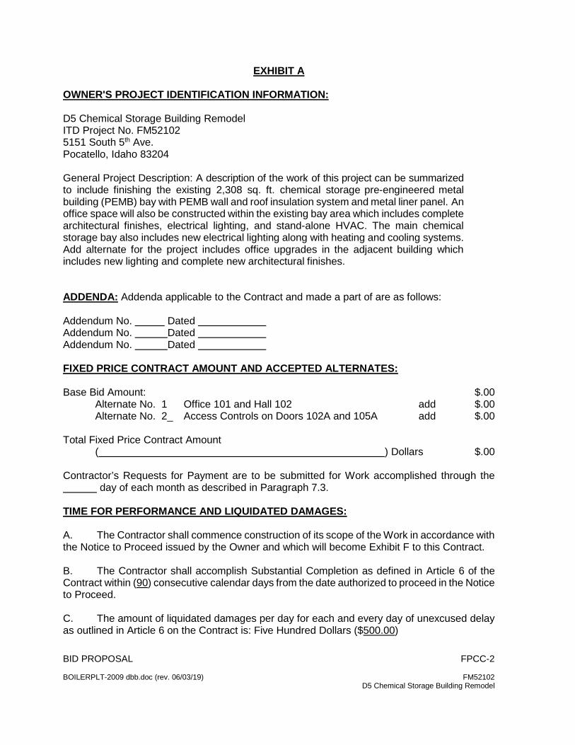
BID PROPOSAL FPCC-2 BOILERPLT-2009 dbb.doc (rev. 06/03/19) FM52102 D5 Chemical Storage Building Remodel
EXHIBIT A OWNER'S PROJECT IDENTIFICATION INFORMATION: D5 Chemical Storage Building Remodel ITD Project No. FM52102 5151 South 5th Ave. Pocatello, Idaho 83204 General Project Description: A description of the work of this project can be summarized to include finishing the existing 2,308 sq. ft. chemical storage pre-engineered metal building (PEMB) bay with PEMB wall and roof insulation system and metal liner panel. An office space will also be constructed within the existing bay area which includes complete architectural finishes, electrical lighting, and stand-alone HVAC. The main chemical storage bay also includes new electrical lighting along with heating and cooling systems. Add alternate for the project includes office upgrades in the adjacent building which includes new lighting and complete new architectural finishes. ADDENDA: Addenda applicable to the Contract and made a part of are as follows: Addendum No. Dated Addendum No. Dated Addendum No. Dated FIXED PRICE CONTRACT AMOUNT AND ACCEPTED ALTERNATES: Base Bid Amount: $.00 Alternate No. 1 Office 101 and Hall 102 add $.00 Alternate No. 2_ Access Controls on Doors 102A and 105A add $.00 Total Fixed Price Contract Amount ( ) Dollars $.00 Contractor’s Requests for Payment are to be submitted for Work accomplished through the day of each month as described in Paragraph 7.3. TIME FOR PERFORMANCE AND LIQUIDATED DAMAGES: A. The Contractor shall commence construction of its scope of the Work in accordance with the Notice to Proceed issued by the Owner and which will become Exhibit F to this Contract. B. The Contractor shall accomplish Substantial Completion as defined in Article 6 of the Contract within (90) consecutive calendar days from the date authorized to proceed in the Notice to Proceed. C. The amount of liquidated damages per day for each and every day of unexcused delay as outlined in Article 6 on the Contract is: Five Hundred Dollars ($500.00)
BID PROPOSAL FPCC-2 BOILERPLT-2009 dbb.doc (rev. 06/03/19) FM52102 D5 Chemical Storage Building Remodel
DRAWINGS AND SPECIFICATIONS The Owner shall furnish the Contractor 1 set of Drawings and Project Manuals SPECIAL CONDITIONS A. In Article 21, Paragraph 21.3, add the Idaho State Building Authority to be named as an additional insured. B. In Article 21, Paragraph 21.5, also provide a separate certificate issued to the Idaho State Building Authority showing the Idaho State Building Authority as an additional insured.
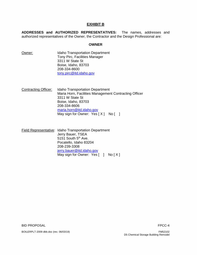
BID PROPOSAL FPCC-4 BOILERPLT-2009 dbb.doc (rev. 06/03/19) FM52102 D5 Chemical Storage Building Remodel
EXHIBIT B ADDRESSES and AUTHORIZED REPRESENTATIVES: The names, addresses and authorized representatives of the Owner, the Contractor and the Design Professional are:
OWNER Owner: Idaho Transportation Department Tony Pirc, Facilities Manager 3311 W State St Boise, Idaho, 83703 208-334-8600 [email protected] Contracting Officer: Idaho Transportation Department Maria Horn, Facilities Management Contracting Officer 3311 W State St Boise, Idaho, 83703 208-334-8606 [email protected]
May sign for Owner: Yes [ X ] No [ ]
Field Representative: Idaho Transportation Department Jerry Bauer, TSEA 5151 South 5th Ave. Pocatello, Idaho 83204 208-239-3308 [email protected] May sign for Owner: Yes [ ] No [ X ]
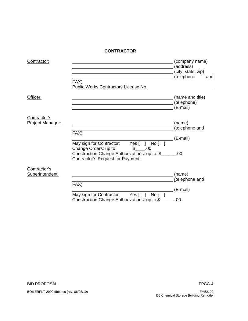
BID PROPOSAL FPCC-4 BOILERPLT-2009 dbb.doc (rev. 06/03/19) FM52102 D5 Chemical Storage Building Remodel
CONTRACTOR Contractor: (company name)
(address) (city, state, zip) (telephone and FAX) Public Works Contractors License No.
Officer: (name and title)
(telephone) (E-mail)
Contractor’s Project Manager: (name)
(telephone and FAX) (E-mail) May sign for Contractor: Yes [ ] No [ ] Change Orders: up to: $____.00 Construction Change Authorizations: up to: $______.00 Contractor’s Request for Payment
Contractor’s Superintendent: (name)
(telephone and FAX) (E-mail) May sign for Contractor: Yes [ ] No [ ] Construction Change Authorizations: up to $______.00
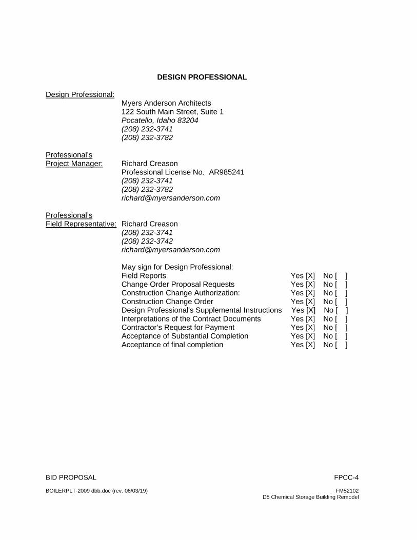
BID PROPOSAL FPCC-4 BOILERPLT-2009 dbb.doc (rev. 06/03/19) FM52102 D5 Chemical Storage Building Remodel
DESIGN PROFESSIONAL
Design Professional:
Myers Anderson Architects 122 South Main Street, Suite 1 Pocatello, Idaho 83204 (208) 232-3741 (208) 232-3782
Professional’s Project Manager: Richard Creason
Professional License No. AR985241 (208) 232-3741 (208) 232-3782 [email protected]
Professional’s Field Representative: Richard Creason
(208) 232-3741 (208) 232-3742 [email protected] May sign for Design Professional: Field Reports Yes [X] No [ ] Change Order Proposal Requests Yes [X] No [ ] Construction Change Authorization: Yes [X] No [ ] Construction Change Order Yes [X] No [ ] Design Professional's Supplemental Instructions Yes [X] No [ ] Interpretations of the Contract Documents Yes [X] No [ ] Contractor’s Request for Payment Yes [X] No [ ] Acceptance of Substantial Completion Yes [X] No [ ] Acceptance of final completion Yes [X] No [ ]
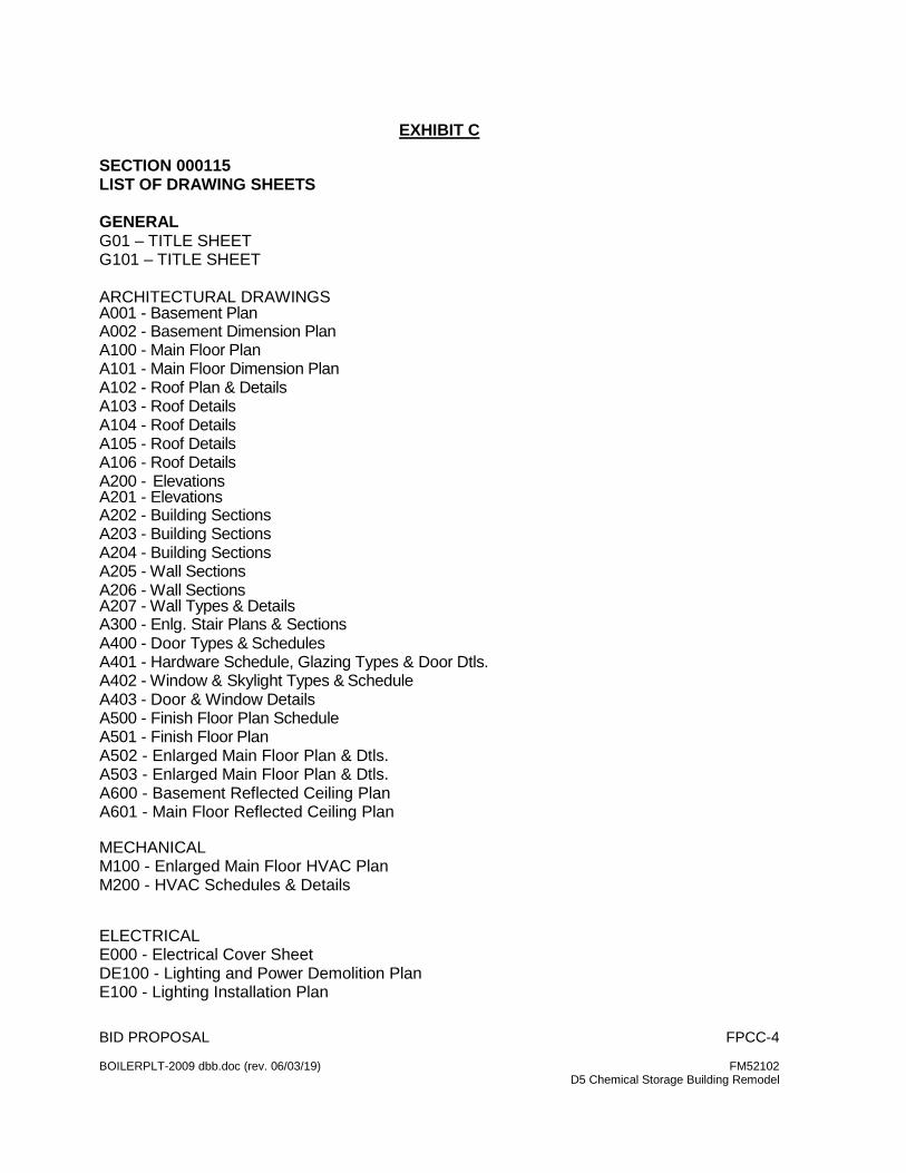
BID PROPOSAL FPCC-4 BOILERPLT-2009 dbb.doc (rev. 06/03/19) FM52102 D5 Chemical Storage Building Remodel
EXHIBIT C
SECTION 000115 LIST OF DRAWING SHEETS GENERAL G01 – TITLE SHEET G101 – TITLE SHEET ARCHITECTURAL DRAWINGS A001 - Basement Plan A002 - Basement Dimension Plan A100 - Main Floor Plan A101 - Main Floor Dimension Plan A102 - Roof Plan & Details A103 - Roof Details A104 - Roof Details A105 - Roof Details A106 - Roof Details A200 - Elevations A201 - Elevations A202 - Building Sections A203 - Building Sections A204 - Building Sections A205 - Wall Sections A206 - Wall Sections A207 - Wall Types & Details A300 - Enlg. Stair Plans & Sections A400 - Door Types & Schedules A401 - Hardware Schedule, Glazing Types & Door Dtls. A402 - Window & Skylight Types & Schedule A403 - Door & Window Details A500 - Finish Floor Plan Schedule A501 - Finish Floor Plan A502 - Enlarged Main Floor Plan & Dtls. A503 - Enlarged Main Floor Plan & Dtls. A600 - Basement Reflected Ceiling Plan A601 - Main Floor Reflected Ceiling Plan MECHANICAL M100 - Enlarged Main Floor HVAC Plan M200 - HVAC Schedules & Details ELECTRICAL E000 - Electrical Cover Sheet DE100 - Lighting and Power Demolition Plan E100 - Lighting Installation Plan
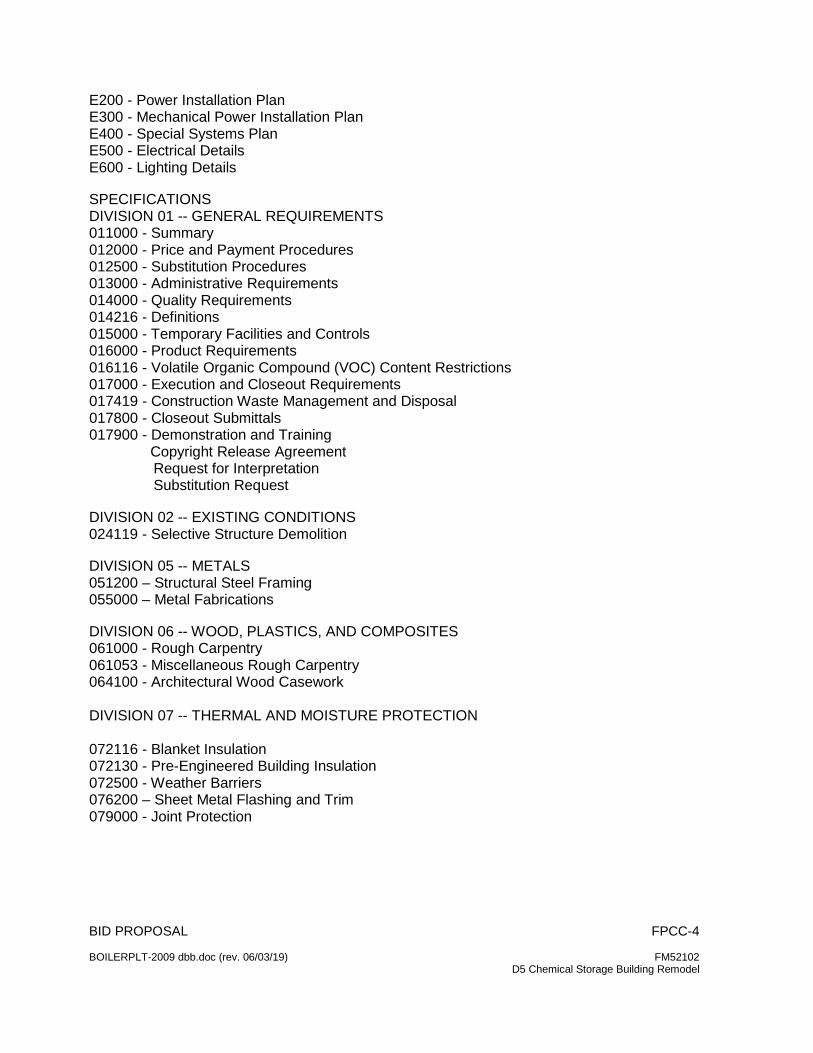
BID PROPOSAL FPCC-4 BOILERPLT-2009 dbb.doc (rev. 06/03/19) FM52102 D5 Chemical Storage Building Remodel
E200 - Power Installation Plan E300 - Mechanical Power Installation Plan E400 - Special Systems Plan E500 - Electrical Details E600 - Lighting Details SPECIFICATIONS DIVISION 01 -- GENERAL REQUIREMENTS 011000 - Summary 012000 - Price and Payment Procedures 012500 - Substitution Procedures 013000 - Administrative Requirements 014000 - Quality Requirements 014216 - Definitions 015000 - Temporary Facilities and Controls 016000 - Product Requirements 016116 - Volatile Organic Compound (VOC) Content Restrictions 017000 - Execution and Closeout Requirements 017419 - Construction Waste Management and Disposal 017800 - Closeout Submittals 017900 - Demonstration and Training Copyright Release Agreement Request for Interpretation Substitution Request DIVISION 02 -- EXISTING CONDITIONS 024119 - Selective Structure Demolition DIVISION 05 -- METALS 051200 – Structural Steel Framing 055000 – Metal Fabrications DIVISION 06 -- WOOD, PLASTICS, AND COMPOSITES 061000 - Rough Carpentry 061053 - Miscellaneous Rough Carpentry 064100 - Architectural Wood Casework DIVISION 07 -- THERMAL AND MOISTURE PROTECTION 072116 - Blanket Insulation 072130 - Pre-Engineered Building Insulation 072500 - Weather Barriers 076200 – Sheet Metal Flashing and Trim 079000 - Joint Protection
BID PROPOSAL FPCC-4 BOILERPLT-2009 dbb.doc (rev. 06/03/19) FM52102 D5 Chemical Storage Building Remodel
DIVISION 08 -- OPENINGS 081214 – Standard Steel Frames 081314 – Standard Steel Doors 081416 - Flush Wood Doors 087100 - Door Hardware 088000 - Glazing DIVISION 09 -- FINISHES 092216 - Non-Structural Metal Framing 096500 – Resilient Flooring DIVISION 10 -- SPECIALTIES 104400 – Fire Protection Specialties DIVISION 13 -- SPECIAL CONSTRUCTION 133419 – Metal Building Systems MECANICAL SPECIFICATIONS DIVISION 23 HEATING, VENTILATING AND AIR CONDITIONING 230500 – Common Work Results for HVAC 230548 – Vibration and Seismic Controls for HVAC Piping and Equipment 231123 – Facility Natural Gas Systems 233423 – HVAC Power Ventilators 233713 – Diffusers, Registers, and Grilles 238113 – Packaged Terminal Air-Conditioners 238239 – High Intensity Space Heaters SITE AND INFRASTRUCTURE DIVISION 32 EXERIOR IMPROVEMENTS 323113 – Chain Link Fences and Gates END OF SECTION 000110
BID PROPOSAL FPCC-5 BOILERPLT-2009 dbb.doc (rev. 06/03/19) FM52102 D5 Chemical Storage Building Remodel
EXHIBIT D
CONTRACTOR’S AFFIDAVIT CONCERNING TAXES
STATE OF ___________________) COUNTY OF _________________) Pursuant to the Title 63, Chapter 15, Idaho Code I, the undersigned, being duly sworn, depose and certify that all taxes, excises and license fees due to the State or its taxing units, for which I or my property is liable then due or delinquent, has been paid, or arrangements have been made, before entering into a Contract for construction of any public works in the State of Idaho. SEAL Name of Contractor Address City and State By: (Signature) Subscribed and sworn to before me this ___________________ day of _________________, . NOTARY PUBLIC Residing at: Commission expires:
BID PROPOSAL FPCC-6 BOILERPLT-2009 dbb.doc (rev. 06/03/19) FM52102 D5 Chemical Storage Building Remodel
EXHIBIT E NAMED SUBCONTRACTORS: Pursuant to Section 67-2310, Idaho Code, commonly known as the naming law, the names and addresses of the entities who will perform the plumbing, heating and air conditioning and electrical work were named in the bid and are as follows: Plumbing (PWCL Category 15400) (Name) (Address) Idaho Public Works Contractors License No. Idaho Plumbing Contractors License No. Heating Ventilating & Air Conditioning (PWCL Category 15700-HVAC)
(Name) (Address) Idaho Public Works Contractors License No.
Idaho HVAC Contractors License No. Electrical (PWCL Category 1600) (Name) (Address) Idaho Public Works Contractors License No. Idaho Electrical Contractors License No.
BID PROPOSAL FPCC-7 BOILERPLT-2009 dbb.doc (rev. 06/03/19) FM52102 D5 Chemical Storage Building Remodel
EXHIBIT F DATE COMPANY NAME Attn: NAME ADDRESS CITY STATE ZIP RE: ITD FM_____ - CONTRACT NOTICE TO PROCEED Dear Mr. ____________________: Attached is the executed contract, number FM_____, between the Idaho Transportation Department and _______________________________ for the ____________________ services at our ______________________________ location. Please make contact with ____________________________ to initiate the work as outlined in the attached document. His contact information is: NAME EMAIL 208- ___-____ We thank you for your interest to work with the Idaho Department of Transportation and hope that you will consider future opportunities. Please contact me at 208-334-8606 if you have any questions, Maria Horn Facility Management Contracting Officer Idaho Transportation Department Attachment
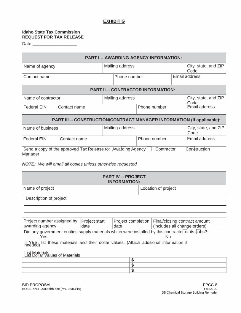
BID PROPOSAL FPCC-8 BOILERPLT-2009 dbb.doc (rev. 06/03/19) FM52102 D5 Chemical Storage Building Remodel
EXHIBIT G
Idaho State Tax Commission REQUEST FOR TAX RELEASE Date:
PART I -- AWARDING AGENCY INFORMATION:
Name of agency Mailing address City, state, and ZIP Code
Contact name Phone number Email address
PART II -- CONTRACTOR INFORMATION:
Name of contractor Mailing address City, state, and ZIP Code
Federal EIN Contact name Phone number Email address
PART III -- CONSTRUCTION/CONTRACT MANAGER INFORMATION (if applicable):
Name of business Mailing address City, state, and ZIP Code
Federal EIN Contact name Phone number Email address
Send a copy of the approved Tax Release to: Awarding Agency Contractor Construction Manager NOTE: We will email all copies unless otherwise requested
PART IV -- PROJECT INFORMATION:
Name of project Location of project
Description of project
Project number assigned by awarding agency
Project start date
Project completion date
Final/closing contract amount (includes all change orders)
Did any government entities supply materials which were installed by this contractor or its subs?: ______ Yes _______________________________________________ No If YES, list these materials and their dollar values. (Attach additional information if needed) List Materials List Dollar Values of Materials $ $ $
1
BID PROPOSAL FPCC-8 BOILERPLT-2009 dbb.doc (rev. 06/03/19) FM52102 D5 Chemical Storage Building Remodel
Send to: Contract Desk/Sales Tax Audit Idaho State Tax Commission PO Box 36 Boise ID 83722-0410
Phone: (208) 334-7618 • Fax: (208) 332-6619 • Email: [email protected] NOTE: Please allow 30 days to process a Tax Release Request. You must send a complete, signed
Form WH-5 Public Works Contract Report to the Idaho State Tax Commission to complete this request.
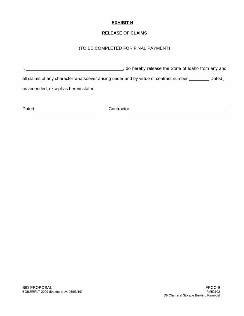
BID PROPOSAL FPCC-9 BOILERPLT-2009 dbb.doc (rev. 06/03/19) FM52102 D5 Chemical Storage Building Remodel
EXHIBIT H
RELEASE OF CLAIMS
(TO BE COMPLETED FOR FINAL PAYMENT)
I, , do hereby release the State of Idaho from any and
all claims of any character whatsoever arising under and by virtue of contract number Dated
as amended, except as herein stated.
Dated Contractor
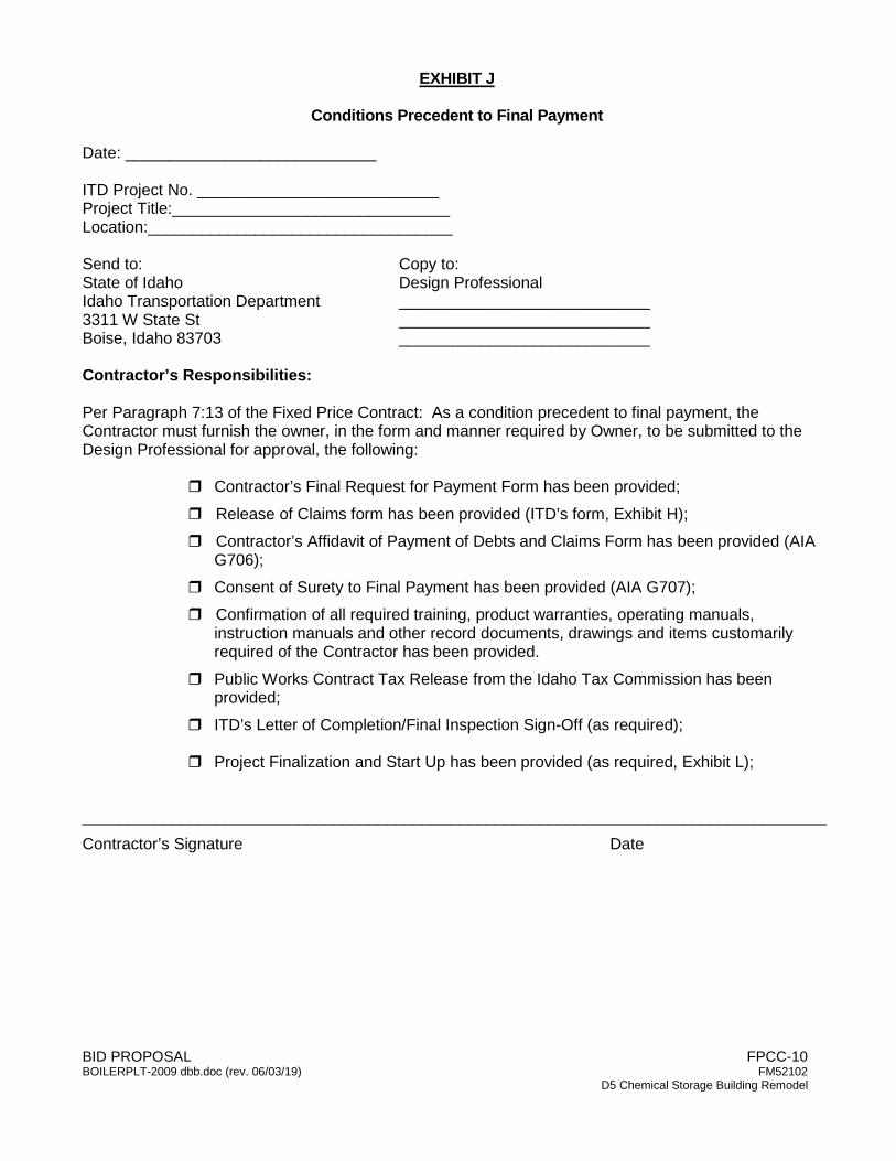
BID PROPOSAL FPCC-10 BOILERPLT-2009 dbb.doc (rev. 06/03/19) FM52102 D5 Chemical Storage Building Remodel
EXHIBIT J
Conditions Precedent to Final Payment Date: ____________________________ ITD Project No. ___________________________ Project Title:_______________________________ Location:__________________________________ Send to: Copy to: State of Idaho Design Professional Idaho Transportation Department ____________________________ 3311 W State St ____________________________ Boise, Idaho 83703 ____________________________ Contractor’s Responsibilities: Per Paragraph 7:13 of the Fixed Price Contract: As a condition precedent to final payment, the Contractor must furnish the owner, in the form and manner required by Owner, to be submitted to the Design Professional for approval, the following:
Contractor’s Final Request for Payment Form has been provided; Release of Claims form has been provided (ITD’s form, Exhibit H); Contractor’s Affidavit of Payment of Debts and Claims Form has been provided (AIA
G706); Consent of Surety to Final Payment has been provided (AIA G707); Confirmation of all required training, product warranties, operating manuals,
instruction manuals and other record documents, drawings and items customarily required of the Contractor has been provided.
Public Works Contract Tax Release from the Idaho Tax Commission has been provided;
ITD’s Letter of Completion/Final Inspection Sign-Off (as required);
Project Finalization and Start Up has been provided (as required, Exhibit L); ___________________________________________________________________________________ Contractor’s Signature Date
BID PROPOSAL FPCC-10 BOILERPLT-2009 dbb.doc (rev. 06/03/19) FM52102 D5 Chemical Storage Building Remodel
Design Professional’s Approval for Payment: All Documents Required per Paragraph 7.13 of the Fixed Price Contract All Warranties, Guarantees, etc. have been received, approved and have been
provided. As-Built Drawings have been received, reviewed and approved. Record Drawings have been completed. All of the required copies of the Record
Documents and electronic media are attached and/or uploaded to OMS. All punch list items have been verified and signed off as complete. To the best of my knowledge, information, and belief, and on the basis of my observations and inspections, I certify the Work has been completed in accordance with the terms and conditions of the Contract Documents and that the required documentation required by Paragraph 7.13 of the fixed priced contract has been received. The entire balance, as shown on the attached Final Request for Payment, is due and payable. ___________________________________________________________________________________ Design Professional’s Signature Date
BID PROPOSAL FPCC-11 BOILERPLT-2009 dbb.doc (rev. 06/03/19) FM52102 D5 Chemical Storage Building Remodel
EXHIBIT L
PROJECT FINALIZATION AND START-UP Upon completion of the equipment and systems installation and connections, the contractor shall assemble all equipment factory representative and subcontractors together for system start-up. These people shall assist in start-up and check out their system(s) and remain at the site until the total system operation is acceptable and understood by the agency’s representative(s). The factory representative and system subcontractor shall also give instructions on operation and maintenance of their equipment to the agency’s maintenance and/or operation personnel. To prove acceptance of operation and instruction by the agency’s representative(s), this written statement of acceptance shall be signed below.
“I, the Contractor, associated factory representative and subcontractors, have started each system and the total system; and have proven their normal operation to the agency’s representative(s) and maintenance/operation personnel and have instructed him/them in the operation and maintenance thereof.” Agency’s Representative Contractor Signature Signature Date Date
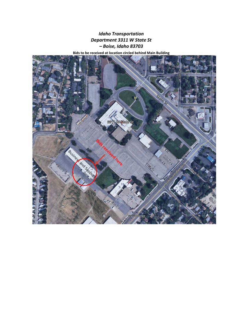
Idaho Transportation Department 3311 W State St
– Boise, Idaho 83703 Bids to be received at location circled behind Main Building

ITD Chemical Storage Building
01 10 00
DIVISION 01 GENERAL CONDITIONS
SECTION 01 10 00
SUMMARY
PART 1 - GENERAL
1.1 SUMMARY
A. Section Includes: 1. Contract description. 2. Work by Owner or Others 3. Contractor's use of Site and premises. 4. Work sequence. 5. Owner occupancy. 6. Permits. 7. Specification conventions. 8. Specification and Drawing Coordination.
1.2 CONTRACT DESCRIPTION
A. A description of the work of this project can be summarized to include finishing the existing
2,308 sq. ft. chemical storage pre-engineered metal building (PEMB) bay with PEMB wall and roof insulation system and metal liner panel. An office space will also be constructed within the existing bay area which includes complete architectural finishes, electrical lighting, and stand-alone HVAC. The main chemical storage bay also includes new electrical lighting along with heating and cooling systems. Add alternate for the project includes office upgrades in the adjacent building which includes new lighting and complete new architectural finishes.
B. Perform Work of Contract under fixed cost Contract with Owner according to
Conditions of Contract.
1.3 WORK BY OWNER OR OTHERS
A. If Owner-awarded contracts interfere with this contract due to work being performed at the same time or at the same Site, Owner will determine the sequence of work under all contracts according to "Work Sequence" and "Contractor's Use of Site and Premises" Articles in this Section.
B. Coordinate Work with utilities of Owner and public or private agencies.
C. Items noted NIC (Not in Contract), will be furnished and installed by Owner.
1.4 CONTRACTOR'S USE OF SITE AND PREMISES
A. Limit use of Site and premises to allow:
1. Owner occupancy. 2. Work by Owner.
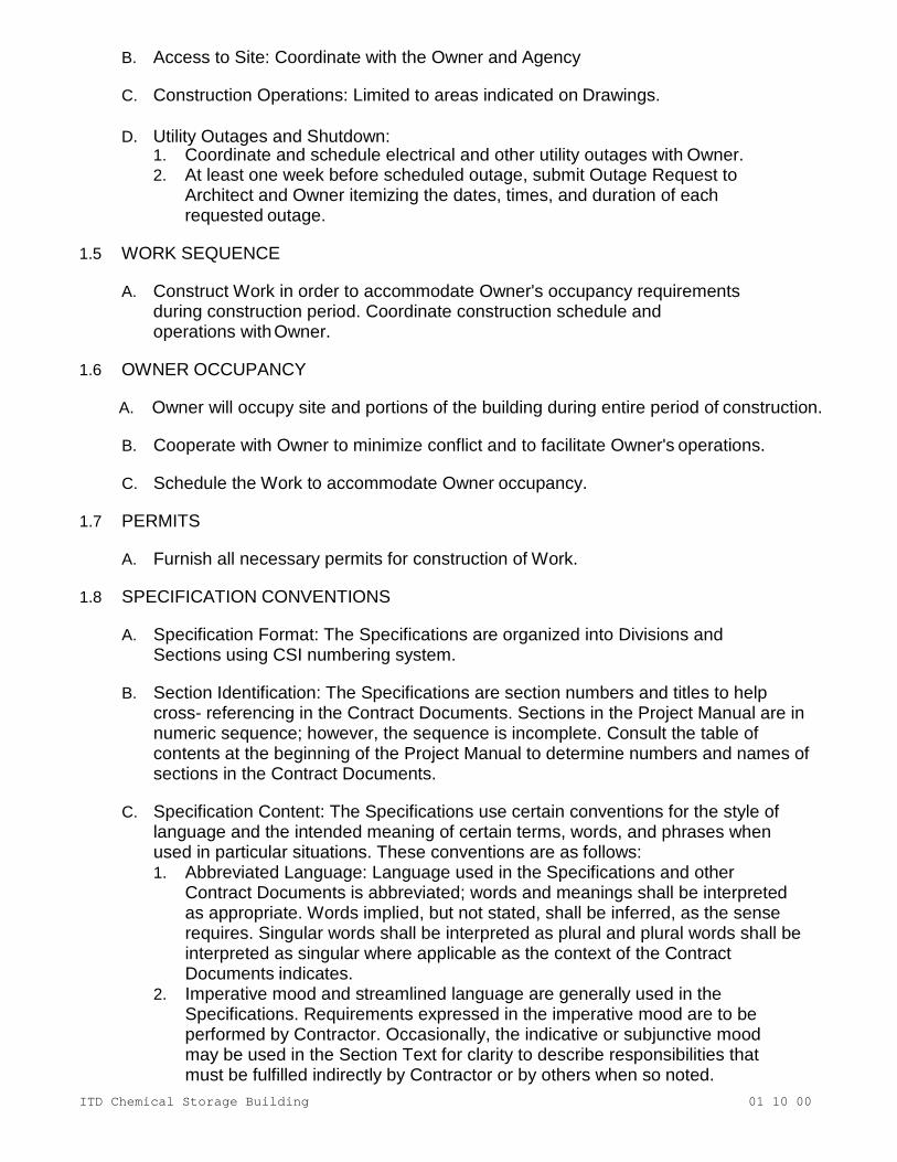
ITD Chemical Storage Building
01 10 00
B. Access to Site: Coordinate with the Owner and Agency
C. Construction Operations: Limited to areas indicated on Drawings.
D. Utility Outages and Shutdown: 1. Coordinate and schedule electrical and other utility outages with Owner. 2. At least one week before scheduled outage, submit Outage Request to
Architect and Owner itemizing the dates, times, and duration of each requested outage.
1.5 WORK SEQUENCE
A. Construct Work in order to accommodate Owner's occupancy requirements
during construction period. Coordinate construction schedule and operations with Owner.
1.6 OWNER OCCUPANCY
A. Owner will occupy site and portions of the building during entire period of construction.
B. Cooperate with Owner to minimize conflict and to facilitate Owner's operations.
C. Schedule the Work to accommodate Owner occupancy.
1.7 PERMITS
A. Furnish all necessary permits for construction of Work.
1.8 SPECIFICATION CONVENTIONS
A. Specification Format: The Specifications are organized into Divisions and
Sections using CSI numbering system.
B. Section Identification: The Specifications are section numbers and titles to help cross- referencing in the Contract Documents. Sections in the Project Manual are in numeric sequence; however, the sequence is incomplete. Consult the table of contents at the beginning of the Project Manual to determine numbers and names of sections in the Contract Documents.
C. Specification Content: The Specifications use certain conventions for the style of
language and the intended meaning of certain terms, words, and phrases when used in particular situations. These conventions are as follows: 1. Abbreviated Language: Language used in the Specifications and other
Contract Documents is abbreviated; words and meanings shall be interpreted as appropriate. Words implied, but not stated, shall be inferred, as the sense requires. Singular words shall be interpreted as plural and plural words shall be interpreted as singular where applicable as the context of the Contract Documents indicates.
2. Imperative mood and streamlined language are generally used in the Specifications. Requirements expressed in the imperative mood are to be performed by Contractor. Occasionally, the indicative or subjunctive mood may be used in the Section Text for clarity to describe responsibilities that must be fulfilled indirectly by Contractor or by others when so noted.
ITD Chemical Storage Building
01 10 00
a. The words “shall,” “shall be,” or “shall comply with,” depending on the context, are implied where a colon (:) is used within a sentence or phrase.
1.9 SPECIFICATION AND DRAWING COORDINATION
A. The specifications and drawings are complementary to each other with neither one
has precedence over the other. Should there be a conflict between specifications and drawings, request clarification from the Architects before proceeding.
B. The drawings within the construction documents are complimentary to each other with no drawing, note or schedule have precedence over the other. Should there be a conflict between drawings notes and schedules, request clarification from the Architects before proceeding.
PART 2 - PRODUCTS - Not
Used PART 3 - EXECUTION -
Not Used END OF SECTION
ITD Chemical Storage Building
01 20 00
SECTION 01 20 00
PRICE AND PAYMENT PROCEDURES
PART 1 - GENERAL
1.1 SECTION INCLUDES A. Schedule of Values B. Application for Payment C. Change procedures D. Defect assessment
1.2 SCHEDULE OF VALUES
A. Submit printed schedule on AIA G703 - Continuation Sheet for G702 or Contractor's standard similar form or electronic media printout will be considered for this use
B. Submit Schedule of Values in duplicate within 15 days after date of Owner-Contractor Agreement
C. Format: 1. Use Table of Contents of this Project Manual
a. Identify each line item with number and title of major Specification Section b. Identify line item for site mobilization, bonds and insurance, and
project closeout 2. Include the following Project identification of the Schedule of Values:
a. Project name and location b. Name of General Contractor c. Name of Architect d. Owner’s project number e. Date of submittal
3. Arrange the Schedule of Values in tabular form with separate columns to indicate the following for each item listed: a. Related Specification Section or Division b. Description of the Work c. Change Orders (numbers) that affect value. d. Dollar value
4. Provide a breakdown of the Contract Sum in enough detail to facilitate continued evaluations of Applications of Payment and progress reports. a. Coordinate with the Project Manual table of contents b. Provide several line items for principal subcontract amounts,
where appropriate c. Round amounts to nearest whole dollar d. Total shall equal the Contract amount
5. Provide a separate line item in the Schedule of Values for each part of the Work where Applications for Payment may include materials or equipment purchased or fabricated and stored, but not installed. a. Differentiate between items stored on-site and items stored off-site
1) Include evidence of insurance or bonded warehousing if required. 6. Provide separate line items in the Schedule of Values for initial cost of
materials, for each subsequent stage of completion, and for total installed value of that part of the Work
ITD Chemical Storage Building
01 20 00
7. Each item in the Schedule of Values and Applications for Payment shall be complete
a. Include total cost and proportionate share of general overhead and profit for each item.
8. Temporary facilities and other major cost items that are not direct cost of actual work-in-place may be shown as separate line items in the Schedule of Values or distributed as general overhead expense, at Contractor’s option
D. Include within each line item, direct proportional amount of Contractor's overhead and profit
E. Revise schedule to list approved Change Orders with each Application for Payment
1.3 APPLICATION FOR PAYMENT A. Submit one copies of each Application for Payment on AIA G702 -
Application and Certificate for Payment and AIA G703 - Continuation Sheet for G702.
B. Content and Format: 1. Use Schedule of Values for listing items in Application for Payment
C. Complete every entry on form D. Execute by a person authorized to sign legal documents on behalf of Contractor
1. Architect will return incomplete applications without action. 2. Entries shall match data on the Schedule of Values 3. Include amounts of Change Orders approved before last day of construction
period covered by application E. Each Application for Payment shall be consistent with previous applications and
payments as certified by Architect and paid for by Owner F. Payment Application Times:
1. The date for each progress payment is indicated in the Agreement between Owner and Contractor
2. The period of construction work covered by each Application of Payment is the period indicated in the Agreement
G. Administrative actions and submittals that must precede or coincide with submittal of first Application of Payment include the following: 1. List of subcontractors (if applicable) 2. Schedule of Values 3. Submittals Schedule (preliminary if not final) 4. List of Contractor’s staff assignments 5. Copies of permits (if applicable) 6. Copies of authorizations and licenses form authorities having
jurisdiction for performance of the Work 7. Initial progress report
H. Submit with transmittal letter as specified for Submittals in Section 01 33 00 - Submittal Procedures 1. One signed original copy of Application for Payment to the Architect
I. Submit updated construction schedule with each Application for Payment J. After issuing the Certificate of Substantial Completion, submit an Application of
ITD Chemical Storage Building
01 20 00
Payment showing 95 percent completion of portion of the Work claimed as substantially complete 1. Include documentation supporting claim that the Work is substantially
complete and a statement showing an accounting of changes to the Contract Sum
K. Submit final Application for Payment showing 100 percent completion with releases and supporting documentation not previously submitted and accepted, including, but not limited, to the following: 1. As-Built Drawings 2. Operation and Maintenance Manual 3. All Warranties and Guarantees 4. Insurance certificates for products and completed operations where
required and proof that taxes, fees, and similar obligations were paid 5. AIA Document G706, “Contractor’s Affidavit of Payment of Debts and Claims” 6. AIA Document G707, “Consent of Surety to Final Payment” 7. Letter stating all punch list items are completed and accepted 8. Release of Claims form. 9. Tax Release from the Idaho Tax Commission – Submit Exhibit G FPCC-47
to Idaho Tax Commission to obtain Tax Release. 10. Project Finalization and Start-Up Form
1.4 CHANGE PROCEDURES
A. Submittals: 1. Submit name of individual who is authorized to receive change
documents and is responsible for informing others in Contractor's employ or Subcontractors of changes to the Work
B. Requests for Interpretation (RFI) and Clarifications: 1. Allot time in construction scheduling for liaison with Architect; establish
procedures for handling queries and clarifications a. Use the accompanying Request for Interpretation form or similar
form for requesting interpretations 2. Architect may respond with a direct answer on the Request for
Interpretation form, or a written clarification, AIA G710 - Architect's Supplemental Instruction, or Proposal Request
C. Minor changes in work: 1. The Architect may use Architect Supplemental Instructions(ASI) to order
minor changes in the Work not involving adjustment to Contract Sum/Price or Contract Time
2. If the Contractor believes a cost is involved, he must inform the Architect in writing of his related costs within ten (10) days
D. Proposal Request: 1. The Architect may issue a Proposal Request including a detailed
description of proposed change with supplementary or revised Drawings and specifications, and change in Contract Time for executing the change a. Within seven (7) days after receipt of Proposal Request, The
Contractor shall submit a quotation proposing cost adjustments to the Contract Sum and the Contract Schedule necessary to execute the change 1) Include a list of quantities of products required or eliminated
and unit costs, with total amount of purchases and credits to
ITD Chemical Storage Building
01 20 00
be made a) If requested, furnish survey data to substantiate quantities.
2) Indicate applicable taxes, delivery charges, equipment rental, and amounts of trade discounts
3) Include a Schedule that indicates the effect of the change, including, but not limited to, changes in activity duration, start and finish times, and activity relationship
2. Contractor may propose changes by submitting a request for change to Architect, describing proposed change and its full effect on the Work a. Include a statement describing reason for the change, and effect on
Contract Sum and Contract Time with full documentation and a statement describing effect on Work by separate or other Contractors 1) Include a list of quantities of products required or eliminated
and unit costs, with total amount of purchases and credits to be made a) If requested, furnish survey data to substantiate quantities
b. Indicate applicable taxes, delivery charges, equipment rental, and amounts of trade discounts
c. Include a Schedule that indicates the effect of the change, including, but not limited to, changes in activity duration, start and finish times, and activity relationship
d. Document requested substitutions in accordance with Section 01 60 00 - Product Requirements
E. Change Order Procedures 1. Construction Change Directive: Architect may issue AIA G714 - Construction
Change Directive signed by Owner, instructing Contractor to proceed with change in the Work, for subsequent inclusion in a Change Order a. Document will describe changes in the Work, and designate
method of determining any change in Contract Sum or Contract Time 1) Promptly execute change.
b. Documentation: 1) Maintain detailed records of change in cost and/or time with
sufficient data as the Architect may prescribe for the work required by the Construction Change Directive
c. After completion of change, submit an itemized account and supporting data necessary to substantiate cost and time adjustments to the Contract
2. Execution of Change Orders: Architect will issue Change Orders using AIA G701 - Change Order for signatures of parties as provided in Conditions of the Contract
3. Correlation Of Contractor Submittals: a. Promptly revise Schedule of Values and Application for Payment
forms to record each authorized Change Order as separate line item and adjust Contract Sum/Price
b. Promptly revise progress schedules to reflect change in Contract Time, revise sub-schedules to adjust times for other items of work affected by the change, and resubmit
c. Promptly enter changes in Project Record Documents
ITD Chemical Storage Building
01 20 00
1.5 DEFECT ASSESSMENT A. Replace the Work, or portions of the Work, not conforming to specified requirements B. If, in the opinion of Architect, it is not practical to remove and replace the Work,
Architect will direct appropriate remedy or adjustment to the contract amount C. The defective Work to remain, the contract amount may be adjusted to new
amount at discretion of Architect and Owner D. Defective Work partially repaired according to instructions of Architect and
Owner, the contract amount may be adjusted to new amount at discretion of Architect and Owner.
E. Authority of Architect on behalf of the Owner to assess defects and identify payment adjustments is final.
F. Nonpayment for Rejected Products: 1. Payment will not be made for rejected products for any of the following reasons:
a. Products wasted or disposed of in a manner that is not acceptable b. Products determined as unacceptable before or after placement c. Products not completely unloaded from transporting vehicle d. Products placed beyond lines and levels of the required Work e. Products remaining on hand after completion of the Work f. Loading, hauling, and disposing of rejected products
PART 2 - PRODUCTS - Not
Used PART 3 - EXECUTION
- Not Used END OF
SECTION

ITD Chemical Storage Building
01 23 00
SECTION 01 23
00 ALTERNATES
PART 1 - GENERAL
1.1 SUMMARY
A. Section includes administrative and procedural requirements for alternates.
1.2 DEFINITIONS
A. Alternate: An amount proposed by bidders and stated on the Bid Form for certain work defined in the bidding requirements that may be added to the base bid amount if the Owner decides to accept a corresponding change either in the amount of construction to be completed or in the products, materials, equipment, systems, or installation methods described in the Contract Documents. 1. Alternates described in this Section are part of the Work only if enumerated in the
Agreement. 2. The cost or credit for each alternate is the net addition to or deduction from the
Contract Sum to incorporate alternates into the Work. No other adjustments are made to the Contract Sum.
1.3 PROCEDURES
A. Coordination: Revise or adjust affected adjacent work as necessary to completely integrate work of the alternate into Project.
1. Include as part of each alternate, miscellaneous devices, accessory objects, and
similar items incidental to or required for a complete installation whether or not indicated as part of alternate.
2. Additive Alternates should be kept to a minimum and must be clear, precise and
independent of other additive alternates.
B. Execute accepted alternates under the same conditions as other work of the Contract.
C. Schedule: A schedule of alternates is included at the end of this Section. Specification Sections referenced in schedule contain requirements for materials necessary to achieve the work described under each alternate.
PART 2 - PRODUCTS
(Not Used) PART 3 -
EXECUTION

ITD Chemical Storage Building
01 23 00
3.1 SCHEDULE OF ALTERNATES
A. Alternate No. 1: Office 101 and Hall 102
1. Base Bid: All work associated with insulating and installing metal liner panel throughout the existing Dry Storage 104. Base bid also includes all work associated with constructing new Office 100. Base bid includes complete interior finishes along with full electrical, HVAC, and gas piping in Office 100 and Dry Storage 104. Base bid also includes repair of existing overhead door 104A, repair of existing damaged metal building above overhead door 104A, Infill of existing overhead door between dry storage 104 and Maintenance 103, and replacement of existing door 104B with new door and access control device.
2. Add Alternate: All work associated with office 101 and Hall 102 as indicated on the drawings and in the specifications.
B. Alternate No. 2: Access Control on Doors 102A and 105A
1. Base Bid: Existing doors 102A and 105A shall remain as is, preserve and protect. Paint existing door and frame 102A on both interior and exterior sides as part of add alternate #1.
2. Add Alternate: All work associated with replacing doors 102A and 105A including providing new access control and door hardware. Alternate includes all electrical wiring and raceways associated with new access control for these two doors as indicated on the electrical drawings.
END OF SECTION

ITD Chemical Storage Building
01 25 00
SECTION 01 25 00
SUBSTITUTION
PROCEDURES
PART 1 - GENERAL
1.1 SECTION INCLUDES A. Quality assurance B. Product options C. Product Substitutions Prior to Bidding D. Product Substitution During Construction
1.2 QUALITY ASSURANCE
A. Contract is based on products and standards established in Contract Documents without consideration of proposed substitutions
B. Products specified define standard of quality, type, function, dimension, appearance, and performance required
C. Substitution Proposals: Permitted for specified products except where specified otherwise
D. Do not substitute products unless substitution has been accepted and approved in writing by Architect
1.3 PRODUCT OPTIONS
A. See Section 01 60 00 - Product Requirements
1.4 PRODUCT SUBSTITUTIONS PRIOR TO BIDDING A. Instructions to Bidders specify time restrictions and requirement for submitting
Requests for Substitutions during bidding period 1. Requests received after that time may be considered or rejected at
discretion of Architect B. Architect will consider requests for substitution as applicable to Owner’s requirements C. Architect will consider Contractor’s request for substitution when all of the
following conditions are satisfied 1. Substitution request is fully documented and properly submitted 2. Requested substitution is compatible with other portions of the Work 3. Requested substitution is consistent with the Contract Documents and will
produce indicated results 4. Requested substitution does not require extensive revisions to the
Contract Documents 5. If requested substitution involves more than one contractor, requested
substitution has been coordinated with other portions of the Work, is uniform and consistent, is compatible with other products, and is acceptable to all contractors involved
D. A request substitution constitutes a representation that Bidder:
ITD Chemical Storage Building
01 25 00
1. Has investigated proposed product and determined that it meets or exceeds quality level of specified product.
2. Waives claims for additional costs or time extension, which may subsequently become apparent
3. Requested substitution will not adversely affect Project Construction Schedule 4. Requested substitution has received necessary approvals of authorities having
jurisdiction 5. Requested substitution has been coordinated with other portions of the Work 6. Requested substitution will provide same warranty as the specified product 7. Will reimburse Owner and Architect for review or redesign services
associated with re-approval by authorities having jurisdiction 8. Will coordinate installation and make changes to other Work, which may be
required for the Work to be complete with no additional cost to Owner E. Document each request with complete data substantiating compliance of
proposed Substitution with Contract Document. F. All substitution require written request Substitution Submittal Procedure:
1. Submit one copy of request for Substitution for consideration a. Limit each request to one proposed Substitution
2. Submit Shop Drawings, Product Data, and certified test results attesting to proposed product equivalence. a. Burden of proof is on proposer
3. The Architect/Engineer will list approved substitutions in the addendums G. If the above conditions are not satisfied, Architect will retain requests without action
1.5 PRODUCT SUBSTITUTION DURING CONSTRUCTION
A. Substitutions will NOT be considered: 1. Without approval prior to bidding 2. When they are indicated or implied on Shop Drawing/Product Data submittals 3. When acceptance will require revision to Contract Documents
B. Written Request for Substitutions may be considered when a product becomes unavailable or the delivery time will delay completion of the project within the require completion time through no fault of Contractor. 1. Contractor shall provide written support data form product
supplier/manufacturer that product is no longer available and /or delivery schedule will delay completion of the project.
C. Document each request with complete data substantiating compliance of proposed Substitution with Contract Document
D. A substitution request constitutes a representation that Contractor: 1. Has investigated that the specified product is indeed unavailable or the
delivery time will not delay completion of the project within the require completion time
2. Has investigated proposed product and determined that it meets or exceeds quality level of specified product
3. Will provide same warranty as the specified product 4. Will coordinate installation and make changes to other Work, which may be
required for the Work to be complete with no additional cost to Owner. 5. Waives claims for additional costs or time extension, which may
subsequently become apparent. 6. Will reimburse Owner and Architect/Engineer for review or redesign

ITD Chemical Storage Building
01 25 00
services associated with re-approval by authorities having jurisdiction. E. Substitution Submittal Procedure:
1. Submit one copy of request for Substitution for consideration a. Limit each request to one proposed Substitution
2. Submit Shop Drawings, Product Data, and certified test results attesting to proposed product equivalence a. Burden of proof is on proposer
3. Architect/Engineer will notify Contractor in writing of decision to accept or reject the substitution
PART 2 - PRODUCTS - Not
Used PART 3 - EXECUTION
- Not Used END OF
SECTION
ITD Chemical Storage Building
01 30 00
SECTION 01 30 00 ADMINISTRATIVE
REQUIREMENTS
PART 1 - GENERAL
1.1 SECTION INCLUDES A. Coordination and Project conditions B. Pre-construction meeting C. Progress meetings D. Pre-installation meetings E. Closeout meeting
1.2 COORDINATION AND PROJECT CONDITIONS
A. Contractor shall provide a full time Superintendent, on site throughout the course of the work to facilitate the coordination of the work.
1. The General Contractor’s Superintendent shall be present on site any time work is being performed by either the contractor or any subcontractor
2. Project Superintendent shall have five (5) years minimum experience as a Superintendent. a. Contractor shall provide experience verification to the Architect prior to
start of work. 3. Changing of the Superintendent during the course of the work shall be
approval by the Architect and Owner is required prior to the change B. Coordinate scheduling, submittals, and Work of various Sections of Project
Manual to ensure efficient and orderly sequence of installation of interdependent construction elements
1. Schedule construction operations in sequence required to obtain the best results where installation of one part of the Work depends on installation of other components, before or after its own installation
2. Coordinate installation of different components with other contracts to ensure maximum accessibility for required maintenance, service, and repair
3. Make adequate provisions to accommodate items scheduled for later installation 4. If necessary, prepare memoranda for distribution to each party involved,
outlining special procedures required for coordination C. Coordinate construction activities to ensure that operations are carried
out with consideration given to conservation of energy, water, and materials.
D. Verify that utility requirements and characteristics of operating equipment are compatible with building utilities 1. Coordinate Work of various Sections having interdependent
responsibilities for installing, connecting to, and placing operating equipment in service
E. Coordinate space requirements, supports, and installation of mechanical and electrical Work indicated diagrammatically on Drawings 1. Follow routing shown for pipes, ducts, and conduit as closely as
ITD Chemical Storage Building
01 30 00
practical; place runs parallel with lines of building 2. Use spaces efficiently to maximize accessibility for other installations,
maintenance, and repairs. 3. Coordination Drawings:
a. Prepare as required to coordinate all portions of Work b. Show relationship and integration of different construction elements that c. require coordination during fabrication or installation to fit in space provided
or to function as intended d. Indicate locations where space is limited for installation and access and
where sequencing and coordination of installations are important F. Coordination Meetings:
1. In addition to other meetings specified in this Section, hold coordination meetings with personnel and Subcontractors to ensure coordination of Work.
G. In finished areas except as otherwise indicated, conceal pipes, ducts, and wiring within construction 1. Coordinate locations of fixtures and outlets with finish elements
H. Coordinate completion and the clean-up of Work of separate Sections in preparation for Substantial Completion and for portions of Work designated for Owner's occupancy
I. After Owner's occupancy of premises, coordinate access to Site for correction of defective Work and Work not complying with Contract Documents, to minimize disruption of Owner's activities
1.3 PRE-CONSTRUCTION MEETING
A. Architect will schedule and preside over meeting after Notice of Award. B. Attendance Required:
1. Architect 2. Owner’s Project Representative 3. Contractor 4. Major Subcontractors
C. Minimum Agenda: 1. Distribution of Owner-Contractor Agreement 2. Submission of executed bonds and insurance certificates 3. Distribution of Contract Documents 4. Submission of list of Subcontractors, list of products, schedule of
values, and Progress Schedule 5. Designation of personnel representing parties in Contract, Owner, and Architect 6. Communication procedures 7. Procedures and processing of requests for interpretations, field
decisions, field orders, submittals, substitutions, Applications for Payments, proposal request, Change Orders, and Contract closeout procedures
8. Scheduling 9. Critical Work sequencing 10. Scheduling activities of Testing Company
D. Architect will record minutes and distribute copies within five days after meeting to participants, with one copy to Contractor, Consulting Engineers, Owner, and those affected by decisions made
ITD Chemical Storage Building
01 30 00
1.4 PROGRESS MEETINGS A. The Architect will schedule and administer Monthly progress meetings
throughout progress of the Work B. Contractor will coordinate meeting space at Project Site C. Architect will prepare agenda with copies for participants and preside at meetings. D. Attendance Required:
1. Job superintendent, 2. Major Subcontractors and suppliers as appropriate to agenda topics
for each meeting 3. Architect 4. Owner
E. Minimum Agenda: 1. Review minutes of previous meetings 2. Review of Work progress 3. Field observations, problems, and decisions 4. Identification of problems impeding planned progress 5. Review of submittal schedule and status of submittals 6. Review of off-Site fabrication and delivery schedules 7. Maintenance of Progress Schedule 8. Corrective measures to regain projected schedules 9. Planned progress during succeeding work period 10. Coordination of projected progress 11. Maintenance of quality and work standards 12. Effect of proposed changes on Progress Schedule and coordination 13. Other business relating to Work
F. Architect will record minutes and distribute copies within five days after meeting to participants, with copies to Contractor, Consulting Engineer, Owner, and those affected by decisions made
1.5 PRE-INSTALLATION MEETINGS
A. When required in individual Specification Sections, Contractor shall convene pre- installation meetings at Project Site before starting Work of specific Section
B. Require attendance of parties directly affecting, or affected by, Work of specific Section C. Notify Architect seven days in advance of meeting date D. Prepare agenda and preside over meeting:
1. Review conditions of installation, preparation, and installation procedures 2. Review coordination with related Work
E. Record minutes and distribute copies to participants within seven days after meeting, with one copy each to Architect, Owner, and those affected by decisions made
1.6 CLOSEOUT MEETING
A. Contractor shall schedule Project Close-out meeting with sufficient time to prepare for requesting Substantial Completion
1. Architect shall preside over meeting and be responsible for minutes. B. Attendance Required:
ITD Chemical Storage Building
01 30 00
1. Contractor 2. Major Subcontractors 3. Architect 4. Consulting Engineer 5. Owner 6. Others appropriate to agenda.
C. Notify Architect seven days in advance of meeting date. D. Minimum Agenda:
1. Start-up of facilities and systems 2. Operations and maintenance manuals 3. Testing, adjusting, and balancing 4. System demonstration and observation 5. Operation and maintenance instructions for Owner's personnel 6. 7. Contractor's inspection of Work 8. Contractor's preparation of an initial "punch list" 9. Procedure to request Architect and Engineers inspection to determine
date of Substantial Completion 10. Completion time for correcting deficiencies 11. Inspections by authorities having jurisdiction 12. Certificate of Occupancy and transfer of insurance responsibilities 13. Partial release of retainage 14. Final cleaning 15. Preparation for final inspection 16. Closeout Submittals:
a. Project record documents b. Operating and maintenance documents c. Operating and maintenance materials d. Affidavits
17. Final Application for Payment 18. Contractor's demobilization of Site 19. Maintenance
E. Record minutes and distribute copies to participants within seven days after meeting, with one copy each to Architect, Owner, and those affected by decisions made
PART 2 - PRODUCTS - Not
Used PART 3 - EXECUTION
– Not Used END OF
SECTION
ITD Chemical Storage Building
01 33 00
SECTION 01 33 00
SUBMITTAL PROCEDURES
PART 1 - GENERAL
1.1 SECTION INCLUDES A. Submittal procedures B. Electronic Submittal Procedures C. Construction progress schedules D. Use of electronic CAD files of Project Drawings E. Product data F. Shop Drawings G. Samples H. Design data I. Test reports J. Certificates K. Manufacturer's instructions L. Contractor review M. Architect review
1.2 SUBMITTAL PROCEDURES
A. Transmit each submittal with AIA G810 - Transmittal Letter or Contractor similar form B. Sequentially number transmittal forms. Mark revised submittals with original
number and sequential alphabetic suffix C. Place a permanent label or title block on each submittal for identification
1. Indicate name of firm or entity that prepared each submittal on label or title block 2. Provide a space approximately 4 by 5 inches on label or beside title block to
record Contractor’s review and approval markings and action taken by Architect
3. Include the following information on label for processing and recording action taken: a. Project name b. Owner’s Project Number c. Date d. Name and address of Architect e. Name and address of Contractor f. Name and address of subcontractor, if any g. Name and address of supplier h. Name and address of Manufacturer i. Unique identifier, including revision number j. Number and title of appropriate Specification Section k. Drawing number and detail references, as appropriate l. Other necessary identification
D. Apply Contractor's stamp, signed or initialed, certifying that review, approval, verification of products required, field dimensions, adjacent construction Work,
ITD Chemical Storage Building
01 33 00
and coordination of information is according to requirements of the Work and Contract Documents
E. Transmit each package with transmittal form individually and appropriately for transmittal and handling 1. On an attached separate sheet, prepared on Contractor’s letterhead, record
relevant information, requests for data, revisions other than those requested by Architect on previous submittals, and deviations from requirements of the Contract Documents, including minor variations and limitations a. Include the same label information as the related submittal.
2. Include Contractor’s certification stating that information submitted complies with requirements of the Contract Documents
3. Provide locations on transmittal form for the following information. a. Project Name b. Owner’s Project Number c. Date d. Destination (To :) e. Source (From :) f. Names of subcontractor, manufacturer, and supplier g. Category and type of submittal h. Submittal purpose and description i. Submittal and transmittal distribution record j. Remarks k. Signature of transmitter
F. Schedule submittals to expedite Project and deliver to Architect at business address. Coordinate submission of related items 1. For each submittal for review, allow 10 days excluding delivery time to
and from Contractor G. Identify variations in Contract Documents and product or system limitations that
may be detrimental to successful performance of completed Work H. Allow space on submittals for Contractor and Architect review stamps I. When revised for resubmission, identify changes made since previous submission J. Distribute copies of reviewed submittals as appropriate
1. Instruct parties to promptly report inability to comply with requirements K. Submittals not requested will not be recognized nor processed L. Complete submittals for each item are required M. Incomplete Submittals:
1. Architect/Engineer will not review 2. Delays resulting from incomplete submittals are not the responsibility of Architect
N. Architect will not review submittal: 1. Received from sources other than General Contractor 2. Without General Contractor’s reviewed stamp 3. Without a completed transmittal form 4. Instruct parties to promptly report inability to comply with requirements
O. Use only final submittals with mark indicating action taken by Architect in connection with construction
1.3 ELECTRONIC SUBMITTAL PROCEDURES
A. At Contractor’s written request, the use of electronic submittals may be
ITD Chemical Storage Building
01 33 00
approved by the architect B. Submitted each submittal in PDF format by the General Contractor only C. Transmit each submittal with electronic equivalent of AIA Form G810
1. Allow space on submittals for Contractor’s review and approval markings 2. Allow space on submittals for Contractor and Architect/Engineer review stamps 3. Include the following information for processing and recording action:
a. Name and address of General Contractor b. Project name c. Owner’s/Architects Project Number d. Date e. Name and address of Architect f. Name and address of Contractor g. Name and address of subcontractor, if any h. Name and address of supplier i. Name and address of Manufacturer j. Unique identifier, including revision number k. Number and title of appropriate Specification Section l. Drawing number and detail references, as appropriate m. Other necessary identification n. Indicate name of firm or entity that prepared each submittal.
D. Email all electronic submittals to [email protected] E. Apply Contractor's stamp, signed or initialed certifying that review, approval,
verification of products required, field dimensions, adjacent construction Work, and coordination of information is in accordance with requirements of the Work and Contract Documents.
F. Transmit each package with transmittal form individually and appropriately for transmittal and handling.
G. Complete submittals for each item are required H. Incomplete Submittals:
1. Architect/Engineer will not review 2. Delays resulting from incomplete submittals are not the responsibility of Architect
I. Use only final submittals with mark indicating action taken by Architect in connection with construction
J. Architect will not review submittal: 1. Received from sources other than General Contractor 2. Without General Contractor’s reviewed stamp 3. Without a completed transmittal form 4. Not in PDF format
K. Schedule submittals to expedite Project, and deliver to Architect at business address. Coordinate submission of related items 1. For each submittal for review, allow 10 days
L. Identify variations from Contract Documents and product or system limitations which may be detrimental to successful performance of completed Work
M. When revised for resubmission, identify changes made since previous submission N. Distribute copies of reviewed submittals as appropriate
1. Instruct parties to promptly report inability to comply with requirements O. Submittals not requested will not be recognized or processed
ITD Chemical Storage Building
01 33 00
P. Use only final submittals with mark indicating action taken by Architect in connection with construction
Q. Electronic submittals shall comply with the same requirements contain elsewhere in this section for paper submittals
1.4 CONSTRUCTION PROGRESS SCHEDULES
A. Submit initial schedules within 7 days after date established in Notice to Proceed 1. After review, resubmit required revised data within ten days
B. Submit revised Progress Schedules with each Application for Payment C. Distribute copies of reviewed schedules to Project site file, subcontractors,
suppliers, and other concerned parties D. Instruct recipients to promptly report, in writing, problems anticipated by
projections indicated in schedules E. Submit computer generated horizontal bar chart with separate line for each
section of Work, identifying first workday of each week 1. Show complete sequence of construction by activity, identifying Work of
separate stages and other logically grouped activities. Indicate early and late start, early and late finish, float dates, and duration
F. Indicate estimated percentage of completion for each item of Work at each submission G. Submit separate schedule of submittal dates for shop drawings, product
data, and samples, including, and dates reviewed submittals will be required from Architect 1. Indicate decision dates for selection of finishes.
H. Indicate delivery dates for Owner furnished products I. Revisions To Schedules:
1. Indicate progress of each activity to date of submittal, and projected completion date of each activity
2. Identify activities modified since previous submittal, major changes in scope, and other identifiable changes
3. Prepare narrative report to define problem areas, anticipated delays, and impact on Schedule a. Report corrective action taken, or proposed, and its effect
1.5 CONTRACTOR’S USE OF ARCHITECT’S ELECTRONIC CAD FILES
A. At General Contractor’s written request, copies of Architect’s Electronic CAD files may be provided to General Contractor for use in connection with this Project, subject to the following conditions: 1. The General Contractor has provide completed and signed Copy Right
Release Agreement and payment of fee for prepared Electronic CAD Files
2. Electronic CAD Files of Project Drawings may only be used to expedite production of Shop Drawings for the Project a. Use for other Projects or purposes is not allowed
3. The drawings cannot be used for any other project 4. The Architect’s title block must be removed by the Contractor
a. The Contractor becomes responsible for the content of the drawings. 1) User is responsible for removing information not normally
ITD Chemical Storage Building
01 33 00
provided on Shop Drawings and removing references to Contract Documents
2) Shop Drawings submitted with information associated with other trades or with references to Contract Documents will not be reviewed and will be immediately returned
5. Use of files is solely at receiver's risk a. Architect does not warrant accuracy of files b. Receiving files in electronic form does not relieve receiver of
responsibilities for measurements, dimensions, and quantities set forth in Contract Documents
c. In the event of ambiguity, discrepancy, or conflict between information on electronic media and that in Contract Documents, notify Architect of discrepancy and use information in hard-copy Drawings and Specifications
6. CAD files may not necessarily represent the latest Contract Documents, existing conditions, and as-built conditions
7. Receiver is responsible for determining and complying with these conditions and for incorporating addenda and modifications
8. Receiver shall not hold Architect responsible for data or file clean-up required to make files usable, nor for error or malfunction in translation, interpretation, or use of this electronic information
9. Receiver shall understand that even though Architect has computer virus scanning software to detect presence of computer viruses, there is no guarantee that computer viruses are not present in files or in electronic media. a. Receiver shall not hold Architect responsible for such viruses or
their consequences, and shall hold Architect harmless against costs, losses, or damage caused by presence of computer virus in files or media.
B. A charge of $50.00 will be required to cover the time required to compile the electronic files and transmit them to the Contractor 1. Only Complete sets of Electronic CAD files will be provided
1.6 PRODUCT DATA
A. Product Data: Submit to Architect for review for assessing conformance with information given and design concept expressed in Contract Documents
B. Submit number of copies Contractor requires, plus two copies Architect/Engineer will retain 1. Include the following information, as applicable:
a. Manufacturer’s written recommendations b. Manufacturer’s product specifications c. Manufacturer’s installation instructions d. Requested color charts indicating full-range selections available e. Manufacturer’s catalog cuts f. Wiring diagrams showing factory-installed wiring g. Printed performance curves h. Operational range diagrams i. Standard product operating and maintenance manuals j. Compliance with recognized trade association standards k. Compliance with recognized testing agency standards l. Application of testing agency labels and seals
ITD Chemical Storage Building
01 33 00
m. Notation of coordination requirements C. Mark each copy to identify applicable products, models, options, and other data
1. Supplement manufacturers' standard data to provide information specific to this Project
D. Indicate product utility and electrical characteristics, utility connection requirements, and location of utility outlets for service for functional equipment and appliances
E. After review, produce copies and distribute according to "Submittal Procedures" Article and for record documents described in Section 01 70 00 - Execution and Closeout Requirements
1.7 SHOP DRAWINGS
A. Shop Drawings: Submit to Architect/Engineer for assessing conformance with information given and design concept expressed in Contract Documents 1. Include the following information, as applicable:
a. Dimensions b. Identification of products c. Fabrication and installation drawings d. Roughing-in and setting diagrams e. Wiring diagrams showing field-installed wiring, including power, signal, and
control wiring f. Shop work manufacturing instructions g. Templates and patterns h. Schedules i. Design calculations j. Compliance with specified standards k. Notation of coordination requirements l. Notation of dimensions established by field measurement
2. Wiring Diagrams: Differentiate between manufacturer-installed and field-installed wiring
3. Sheet Size: Except for templates, patterns, and similar full-size drawings, submit Shop Drawings on sheets at least 8-1/2 by 11 inches but not larger than 30 by 40 inches
B. Architect and Consultants will retain one print each 1. One print must be maintained as required as a Project Record Drawing
C. Indicate special utility and electrical characteristics, utility connection requirements, and location of utility outlets for service for functional equipment and appliances
D. When required by individual Specification Sections, provide Shop Drawings signed and sealed by a professional Engineer responsible for designing components shown on Shop Drawings 1. Include signed and sealed calculations to support design 2. Submit Shop Drawings and calculations in form suitable for submission
to and approval by authorities having jurisdiction 3. Make revisions and provide additional information when required by
authorities having jurisdiction E. Submit number of opaque reproductions Contractor requires, plus two
copies Architect/Engineer will retain F. After review, produce copies and distribute according to "Submittal
ITD Chemical Storage Building
01 33 00
Procedures" Article and for record documents described in Section 01 70 00 - Execution and Closeout Requirements
1.8 SAMPLES
A. Samples: Submit to Architect for assessing conformance with information given and design concept expressed in Contract Documents
B. Samples for Selection as Specified in Product Sections: 1. Submit to Architect/Engineer for aesthetic, color, and finish selection 2. Submit Samples of finishes, textures, and patterns for Architect/Engineer selection
C. Submit Samples to illustrate functional and aesthetic characteristics of products, with integral parts and attachment devices 1. Coordinate Sample submittals for interfacing work
D. Include identification on each Sample, with full Project information E. Submit number of Samples specified in individual Specification Sections;
Architect will retain one Sample F. Reviewed Samples that may be used in the Work indicated in individual
Specification Sections G. Samples will not be used for testing purposes unless specifically stated in
Specification Section H. After review, produce copies and distribute according to "Submittal Procedures" Article
and for record documents described in Section 01 70 00 - Execution and Closeout Requirements
1.9 DESIGN DATA A. When specified in individual specification sections, submit for Architect's
knowledge as contract administrator for Owner B. Submit for information for limited purpose of assessing conformance with
information given and design concept expressed in Contract Documents
1.10 TEST REPORTS A. When specified in individual specification sections, submit reports for
Architect's knowledge as Contract administrator for Owner B. Submit test reports for information for assessing conformance with information
given and design concept expressed in Contract Documents
1.11 CERTIFICATES A. When specified in individual specification sections, submit certification by
manufacturer, installation/application Subcontractor, or Contractor to Architect in quantities specified for Product Data
B. Indicate material or product conforms to or exceeds specified requirements 1. Submit supporting reference data, affidavits, and certifications as appropriate
C. Certificates may be recent or previous test results on material or product but must be acceptable to Architect
1.12 MANUFACTURER'S INSTRUCTIONS
A. When specified in individual specification sections, submit manufacturer's
ITD Chemical Storage Building
01 33 00
installation instructions for Architect's knowledge as Contract administrator B. Submit printed instructions for delivery, storage, assembly, installation, startup,
adjusting, and finishing, to Architect in quantities specified for Product Data C. Indicate special procedures, perimeter conditions requiring special attention, and
special environmental criteria required for application or installation
1.13 CONTRACTOR REVIEW A. Review for compliance with Contract Documents and approve submittals
before transmitting to Architect B. Contractor: Responsible for:
1. Determination and verification of materials including manufacturer's catalog numbers
2. Determination and verification of field measurements and field construction criteria 3. Checking and coordinating information in submittal with requirements of
Work and of Contract Documents 4. Determination of accuracy and completeness of dimensions and quantities 5. Confirmation and coordination of dimensions and field conditions at Site 6. Construction means, techniques, sequences, and procedures 7. Safety precautions 8. Coordination and performance of Work of all trades
C. Stamp, sign or initial, and date each submittal to certify compliance with requirements of Contract Documents
D. Do not fabricate products or begin Work for which submittals are required until approved submittals have been received from Architect
1.14 ARCHITECT/ENGINEER REVIEW
A. Do not make "mass submittals" to Architect 1. "Mass submittals" are defined as six or more submittals or items in one day
or 15 or more submittals or items in one week 2. If "mass submittals" are received, Architect's review time stated above
will be extended as necessary to perform proper review 3. Architect will review "mass submittals" based on priority determined by
Architect after consultation with Owner and Contractor B. Architect will review each submittal, make marks to indicate corrections or
modifications required, and return it 1. Architect will stamp each submittal with an action stamp and will mark
stamp appropriately to indicate action taken C. Informational submittals and other similar data are for Architect information, do not
require Architect responsive action, and will not be reviewed or returned with comment
D. Submittals made by Contractor that are not required by Contract Documents will not be reviewed and may be discarded
E. Submittal approval does not authorize changes to Contract requirements unless accompanied by Change Order or Architect's Supplemental Instruction
F. Architect will review submittals twice 1. All additional reviews shall be paid for by the Contractor at an established fee
ITD Chemical Storage Building
01 33 00
2. Owner may withhold monies due to Contractor to cover additional costs beyond the second submittal review
PART 2 - PRODUCTS - Not
Used PART 3 - EXECUTION
- Not Used END OF
SECTION
ITD Chemical Storage Building
01 50 00
SECTION 01 50 00
TEMPORARY FACILITIES AND CONTROLS
PART 1 - GENERAL
1.1 SUMMARY
A. Section includes requirements for temporary utilities, support facilities, and security and protection facilities.
B. Related Requirements:
1. Section 01 10 00 "Summary" for work restrictions and limitations on utility interruptions.
1.2 USE CHARGES
A. General: Installation and removal of and use charges for temporary facilities shall be included in the Contract Sum unless otherwise indicated. Allow other entities engaged in the Project to use temporary services and facilities without cost, including, but not limited to, Owner's construction forces, Architect, occupants of Project, testing agencies, and authorities having jurisdiction.
B. Sewer Service: Owner will pay sewer-service use charges for sewer usage by all entities
for construction operations.
C. Water Service: Owner will pay water-service use charges for water used by all entities for construction operations.
D. Electric Power Service: Owner will pay electric-power-service use charges for electricity
used by all entities for construction operations.
E. Water and Sewer Service from Existing System: Water from Owner's existing water system is available for use without metering and without payment of use charges. Provide connections and extensions of services as required for construction operations.
F. Electric Power Service from Existing System: Electric power from Owner's existing
system is available for use without metering and without payment of use charges. Provide connections and extensions of services as required for construction operations.
1.3 INFORMATIONAL SUBMITTALS
A. Site Utilization Plan: Show temporary facilities, temporary utility lines and connections, staging areas, construction site entrances, vehicle circulation, and parking areas for construction personnel.
B. Project Identification and Temporary Signs: Show fabrication and installation details,
including plans, elevations, details, layouts, typestyles, graphic elements, and message content.
ITD Chemical Storage Building
01 50 00
C. Fire-Safety Program: Show compliance with requirements of NFPA 241 and authorities having jurisdiction. Indicate Contractor personnel responsible for management of fire-prevention program.
D. Moisture-and Mold-Protection Plan: Describe procedures and controls for protecting materials and construction from water absorption and damage and mold. 1. Describe delivery, handling, and storage provisions for materials subject to water
absorption or water damage. 2. Indicate procedures for discarding water-damaged materials, protocols for
mitigating water intrusion into completed Work, and replacing water-damaged Work.
3. Indicate sequencing of work that requires water, such as sprayed fire-resistive materials, plastering, and terrazzo grinding, and describe plans for dealing with water from these operations. Show procedures for verifying that wet construction has dried sufficiently to permit installation of finish materials.
E. Dust- and HVAC-Control Plan: Submit coordination drawing and narrative that indicates
the dust- and HVAC-control measures proposed for use, proposed locations, and proposed time frame for their operation. Include the following: 1. Locations of dust-control partitions at each phase of work. 2. HVAC system isolation schematic drawing. 3. Location of proposed air-filtration system discharge. 4. Waste-handling procedures. 5. Other dust-control measures. 6. Noise control measures.
1.4 QUALITY ASSURANCE
A. Electric Service: Comply with NECA, NEMA, and UL standards and regulations for temporary electric service. Install service to comply with NFPA 70.
B. Tests and Inspections: Arrange for authorities having jurisdiction to test and inspect each
temporary utility before use. Obtain required certifications and permits.
C. Accessible Temporary Egress: Comply with applicable provisions in the United States Access Board's ADA-ABA Accessibility Guidelines and ICC/ANSI A117.1.
1.5 PROJECT CONDITIONS
A. Temporary Use of Permanent Facilities: Engage Installer of each permanent service to assume responsibility for operation, maintenance, and protection of each permanent service during its use as a construction facility before Owner's acceptance, regardless of previously assigned responsibilities.
PART 2 - PRODUCTS
2.1 EQUIPMENT
A. Fire Extinguishers: Portable, UL rated; with class and extinguishing agent as required by locations and classes of fire exposures.

ITD Chemical Storage Building
01 50 00
PART 3 - EXECUTION
3.1 TEMPORARY FACILITIES, GENERAL
A. Conservation: Coordinate construction and use of temporary facilities with consideration given to conservation of energy, water, and materials. Coordinate use of temporary utilities to minimize waste. 1. Salvage materials and equipment involved in performance of, but not actually
incorporated into, the Work. See other Sections for disposition of salvaged materials that are designated as Owner's property.
3.2 INSTALLATION, GENERAL
A. Locate facilities where they will serve Project adequately and result in minimum interference with performance of the Work. Relocate and modify facilities as required by progress of the Work.
B. Provide each facility ready for use when needed to avoid delay. Do not remove until
facilities are no longer needed or are replaced by authorized use of completed permanent facilities.
3.3 TEMPORARY UTILITY INSTALLATION
A. General: Install temporary service or connect to existing service. 1. Arrange with utility company, Owner, and existing users for time when service can
be interrupted, if necessary, to make connections for temporary services.
B. Sewers and Drainage: Provide temporary utilities to remove effluent lawfully. 1. Connect temporary sewers to municipal system as directed by authorities having
jurisdiction.
C. Water Service: Install water service and distribution piping in sizes and pressures adequate for construction.
D. Sanitary Facilities: Provide temporary toilets, wash facilities, and drinking water for use
of construction personnel. Comply with requirements of authorities having jurisdiction for type, number, location, operation, and maintenance of fixtures and facilities. 1. Toilets: Use of Owner's existing toilet facilities may be permitted, if authorized, as
long as facilities are cleaned and maintained in a condition acceptable to Owner. At Substantial Completion, restore these facilities to condition existing before initial use.
E. Temporary Heating and Cooling: Provide temporary heating and cooling required by
construction activities for curing or drying of completed installations or for protecting installed construction from adverse effects of low temperatures or high humidity. Select equipment that will not have a harmful effect on completed installations or elements being installed. 1. Provide temporary dehumidification systems when required to reduce ambient and
substrate moisture levels to level required to allow installation or application of
ITD Chemical Storage Building
01 50 00
finishes and their proper curing or drying.
F. Isolation of Work Areas in Occupied Facilities: Prevent dust, fumes, and odors from entering occupied areas. 1. Prior to commencing work, isolate the HVAC system in area where work is to be
performed according to coordination drawings.
a. Disconnect supply and return ductwork in work area from HVAC systems servicing occupied areas.
b. Maintain negative air pressure within work area using HEPA-equipped air-filtration units, starting with commencement of temporary partition construction, and continuing until removal of temporary partitions is complete.
2. Maintain dust partitions during the Work. Use vacuum collection attachments on dust- producing equipment. Isolate limited work within occupied areas using portable dust- containment devices.
3. Perform daily construction cleanup and final cleanup using approved, HEPA-filter- equipped vacuum equipment.
G. Electric Power Service: Provide electric power service and distribution system of
sufficient size, capacity, and power characteristics required for construction operations. 1. Install electric power service overhead unless otherwise indicated.
H. Lighting: Provide temporary lighting with local switching that provides adequate
illumination for construction operations, observations, inspections, and traffic conditions. 1. Install and operate temporary lighting that fulfills security and protection
requirements without operating entire system.
I. Telephone Service: Provide temporary telephone service in common-use facilities for use by all construction personnel.
3.4 SUPPORT FACILITIES INSTALLATION
A. Traffic Controls: Comply with requirements of authorities having jurisdiction. 1. Protect existing site improvements to remain including curbs, pavement, and utilities. 2. Maintain access for fire-fighting equipment and access to fire hydrants.
B. Parking: Use designated areas of Owner's existing parking areas for construction
personnel.
C. Project Signs: Provide Project signs as indicated. Unauthorized signs are not permitted. 1. Identification Signs: Provide Project identification signs as indicated on Drawings. 2. Temporary Signs: Provide other signs as indicated and as required to inform
public and individuals seeking entrance to Project. a. Provide temporary, directional signs for construction personnel and visitors.
3. Maintain and touch up signs so they are legible at all times.
D. Waste Disposal Facilities: Comply with requirements specified in Section 017419 "Construction Waste Management and Disposal."
E. Waste Disposal Facilities: Provide waste-collection containers in sizes adequate to
handle waste from construction operations. Comply with requirements of authorities having jurisdiction. Comply with progress cleaning requirements in Section 017300
ITD Chemical Storage Building
01 50 00
"Execution."
F. Lifts and Hoists: Provide facilities necessary for hoisting materials and personnel. 1. Truck cranes and similar devices used for hoisting materials are considered
"tools and equipment" and not temporary facilities.
3.5 SECURITY AND PROTECTION FACILITIES INSTALLATION
A. Protection of Existing Facilities: Protect existing vegetation, equipment, structures, utilities, and other improvements at Project site and on adjacent properties, except those indicated to be removed or altered. Repair damage to existing facilities.
1. Where access to adjacent properties is required in order to affect protection of existing facilities, obtain written permission from adjacent property owner to access property for that purpose.
B. Environmental Protection: Provide protection, operate temporary facilities, and conduct
construction as required to comply with environmental regulations and that minimize possible air, waterway, and subsoil contamination or pollution or other undesirable effects.
C. Temporary Erosion and Sedimentation Control: Comply with requirements of EPA
Construction General Permit or authorities having jurisdiction, whichever is more stringent.
D. Barricades, Warning Signs, and Lights: Comply with requirements of authorities having
jurisdiction for erecting structurally adequate barricades, including warning signs and lighting.
E. Temporary Egress: Maintain temporary egress from existing occupied facilities as
indicated and as required by authorities having jurisdiction.
F. Temporary Fire Protection: Install and maintain temporary fire-protection facilities of types needed to protect against reasonably predictable and controllable fire losses. Comply with NFPA 241; manage fire-prevention program. 1. Prohibit smoking in construction areas. Comply with additional limits on smoking
specified in other Sections. 2. Supervise welding operations, combustion-type temporary heating units, and
similar sources of fire ignition according to requirements of authorities having jurisdiction.
3. Develop and supervise an overall fire-prevention and -protection program for personnel at Project site. Review needs with local fire department and establish procedures to be followed. Instruct personnel in methods and procedures. Post warnings and information.
4. Provide temporary standpipes and hoses for fire protection. Hang hoses with a warning sign stating that hoses are for fire-protection purposes only and are not to be removed. Match hose size with outlet size and equip with suitable nozzles.
3.6 MOISTURE AND MOLD CONTROL
A. Contractor's Moisture-Protection Plan: Describe delivery, handling, storage, installation,
ITD Chemical Storage Building
01 50 00
and protection provisions for materials subject to water absorption or water damage. 1. Indicate procedures for discarding water-damaged materials, protocols for
mitigating water intrusion into completed Work, and replacing water-damaged Work.
2. Indicate sequencing of work that requires water, such as sprayed fire-resistive materials, plastering, and terrazzo grinding, and describe plans for dealing with water from these operations. Show procedures for verifying that wet construction has dried sufficiently to permit installation of finish materials.
3. Indicate methods to be used to avoid trapping water in finished work.
B. Exposed Construction Period: Before installation of weather barriers, when materials are subject to wetting and exposure and to airborne mold spores, protect as follows: 1. Protect porous materials from water damage. 2. Protect stored and installed material from flowing or standing water. 3. Keep porous and organic materials from coming into prolonged contact with concrete. 4. Remove standing water from decks. 5. Keep deck openings covered or dammed.
C. Partially Enclosed Construction Period: After installation of weather barriers but before
full enclosure and conditioning of building, when installed materials are still subject to infiltration of moisture and ambient mold spores, protect as follows:
1. Do not load or install drywall or other porous materials or components, or items with high organic content, into partially enclosed building.
2. Keep interior spaces reasonably clean and protected from water damage. 3. Periodically collect and remove waste containing cellulose or other organic matter. 4. Discard or replace water-damaged material. 5. Do not install material that is wet. 6. Discard and replace stored or installed material that begins to grow mold. 7. Perform work in a sequence that allows wet materials adequate time to dry
before enclosing the material in gypsum board or other interior finishes.
D. Controlled Construction Period: After completing and sealing of the building enclosure but prior to the full operation of permanent HVAC systems, maintain as follows: 1. Control moisture and humidity inside building by maintaining effective dry-in
conditions. 2. Use temporary or permanent HVAC system to control humidity within ranges
specified for installed and stored materials. 3. Comply with manufacturer's written instructions for temperature, relative
humidity, and exposure to water limits.
3.7 OPERATION, TERMINATION, AND REMOVAL
A. Supervision: Enforce strict discipline in use of temporary facilities. To minimize waste and abuse, limit availability of temporary facilities to essential and intended uses.
B. Termination and Removal: Remove each temporary facility when need for its service has
ended, when it has been replaced by authorized use of a permanent facility, or no later than Substantial Completion. Complete or, if necessary, restore permanent construction that may have been delayed because of interference with temporary facility. Repair damaged Work, clean exposed surfaces, and replace construction that cannot be satisfactorily repaired.
ITD Chemical Storage Building
01 50 00
1. Materials and facilities that constitute temporary facilities are property of Contractor. Owner reserves right to take possession of Project identification signs.
2. Remove temporary roads and paved areas not intended for or acceptable for integration into permanent construction. Where area is intended for landscape development, remove soil and aggregate fill that do not comply with requirements for fill or subsoil. Remove materials contaminated with road oil, asphalt and other petrochemical compounds, and other substances that might impair growth of plant materials or lawns. Repair or replace street paving, curbs, and sidewalks at temporary entrances, as required by authorities having jurisdiction.
3. At Substantial Completion, repair, renovate, and clean permanent facilities used during construction period. Comply with final cleaning requirements specified in Section 01 77 00 "Closeout Procedures."
END OF SECTION

ITD Chemical Storage Building
01 60 00
SECTION 01 60 00
PRODUCT REQUIREMENTS
PART 1 - GENERAL
1.1 SUMMARY
A. Section includes administrative and procedural requirements for selection of products for use in Project; product delivery, storage, and handling; manufacturers' standard warranties on products; special warranties; and comparable products.
B. Related Requirements:
1. Section 01 25 00 "Substitution Procedures" for requests for substitutions.
1.2 DEFINITIONS
A. Products: Items obtained for incorporating into the Work, whether purchased for Project or taken from previously purchased stock. The term "product" includes the terms "material," "equipment," "system," and terms of similar intent.
1. Named Products: Items identified by manufacturer's product name, including make
or model number or other designation shown or listed in manufacturer's published product literature that is current as of date of the Contract Documents.
2. New Products: Items that have not previously been incorporated into another project or facility. Products salvaged or recycled from other projects are not considered new products.
3. Comparable Product: Product that is demonstrated and approved by Architect through submittal process to have the indicated qualities related to type, function, dimension, in- service performance, physical properties, appearance, and other characteristics that equal or exceed those of specified product.
B. Basis-of-Design Product Specification: A specification in which a single manufacturer's
product is named and accompanied by the words "basis-of-design product," including make or model number or other designation. In addition to the basis-of-design product description, product attributes and characteristics may be listed to establish the significant qualities related to type, function, in-service performance and physical properties, weight, dimension, durability, visual characteristics, and other special features and requirements for purposes of evaluating comparable products of additional manufacturers named in the specification.
1.3 ACTION SUBMITTALS
A. Comparable Product Request Submittal: Submit request for consideration of each comparable product. Identify basis-of-design product or fabrication or installation method to be replaced. Include Specification Section number and title and Drawing numbers and titles.

ITD Chemical Storage Building
01 60 00
1. Include data to indicate compliance with the requirements specified in "Comparable Products" Article.
2. Architect's Action: If necessary, Architect will request additional information or documentation for evaluation within seven (7) days of receipt of a comparable product request. Architect will notify Contractor of approval or rejection of proposed comparable product request within seven (7) days of receipt of request, or seven (7) days of receipt of additional information or documentation, whichever is later.
a. Form of Architect's Approval of Submittal: As specified in Section 013300
"Submittal Procedures." b. Use product specified if Architect does not issue a decision on use of a
comparable product request within time allocated.
B. Basis-of-Design Product Specification Submittal: Comply with requirements in Section 013300 "Submittal Procedures." Show compliance with requirements.
1.4 QUALITY ASSURANCE
A. Compatibility of Options: If Contractor is given option of selecting between two or more products for use on Project, select product compatible with products previously selected, even if previously selected products were also options.
1.5 PRODUCT DELIVERY, STORAGE, AND HANDLING
A. Deliver, store, and handle products using means and methods that will prevent damage, deterioration, and loss, including theft and vandalism. Comply with manufacturer's written instructions.
B. Delivery and Handling:
1. Schedule delivery to minimize long-term storage at Project site and to prevent
overcrowding of construction spaces. 2. Coordinate delivery with installation time to ensure minimum holding time for items
that are flammable, hazardous, easily damaged, or sensitive to deterioration, theft, and other losses.
3. Deliver products to Project site in an undamaged condition in manufacturer's original sealed container or other packaging system, complete with labels and instructions for handling, storing, unpacking, protecting, and installing.
4. Inspect products on delivery to determine compliance with the Contract Documents and to determine that products are undamaged and properly protected.
C. Storage:
1. Store products to allow for inspection and measurement of quantity or counting of
units. 2. Store materials in a manner that will not endanger Project structure. 3. Store products that are subject to damage by the elements, under cover in a
weathertight enclosure above ground, with ventilation adequate to prevent condensation.
ITD Chemical Storage Building
01 60 00
4. Protect foam plastic from exposure to sunlight, except to extent necessary for period of installation and concealment.
5. Comply with product manufacturer's written instructions for temperature, humidity, ventilation, and weather-protection requirements for storage.
6. Protect stored products from damage and liquids from freezing.
1.6 PRODUCT WARRANTIES
A. Warranties specified in other Sections shall be in addition to, and run concurrent with, other warranties required by the Contract Documents. Manufacturer's disclaimers and limitations on product warranties do not relieve Contractor of obligations under requirements of the Contract Documents.
1. Manufacturer's Warranty: Written warranty furnished by individual manufacturer
for a particular product and specifically endorsed by manufacturer to Owner. 2. Special Warranty: Written warranty required by the Contract Documents to provide
specific rights for Owner.
B. Special Warranties: Prepare a written document that contains appropriate terms and identification, ready for execution.
1. Manufacturer's Standard Form: Modified to include Project-specific information
and properly executed. 2. Specified Form: When specified forms are included with the Specifications,
prepare a written document using indicated form properly executed. 3. See other Sections for specific content requirements and particular requirements
for submitting special warranties.
PART 2 - PRODUCTS
2.1 PRODUCT SELECTION PROCEDURES
A. General Product Requirements: Provide products that comply with the Contract Documents, are undamaged and, unless otherwise indicated, are new at time of installation.
1. Provide products complete with accessories, trim, finish, fasteners, and other items
needed for a complete installation and indicated use and effect. 2. Standard Products: If available, and unless custom products or nonstandard
options are specified, provide standard products of types that have been produced and used successfully in similar situations on other projects.
3. Owner reserves the right to limit selection to products with warranties meeting requirements of the Contract Documents.
4. Where products are accompanied by the term "as selected," Architect will make selection.
5. Descriptive, performance, and reference standard requirements in the Specifications establish salient characteristics of products.
B. Product Selection Procedures:
ITD Chemical Storage Building
01 60 00
1. Sole Product: Where Specifications name a single manufacturer and product, provide the named product that complies with requirements. Comparable products or substitutions for Contractor's convenience will not be considered.
a. Sole product may be indicated by the phrase: "Subject to compliance with
requirements, provide the following: …"
2. Sole Manufacturer/Source: Where Specifications name a single manufacturer or source, provide a product by the named manufacturer or source that complies with requirements. Comparable products or substitutions for Contractor's convenience will not be considered.
a. Sole manufacturer/source may be indicated by the phrase: "Subject to
compliance with requirements, provide products by the following: …"
3. Limited List of Products: Where Specifications include a list of names of both manufacturers and products, provide one of the products listed that complies with requirements. Comparable products or substitutions for Contractor's convenience will not be considered unless otherwise indicated.
a. Limited list of products may be indicated by the phrase: "Subject to
compliance with requirements, provide one of the following: …"
4. Non-Limited List of Products: Where Specifications include a list of names of both available manufacturers and products, provide one of the products listed, or an unnamed product, which complies with requirements.
a. Non-limited list of products is indicated by the phrase: "Subject to compliance
with requirements, available products that may be incorporated in the Work include, but are not limited to, the following: …"
5. Limited List of Manufacturers: Where Specifications include a list of manufacturers'
names, provide a product by one of the manufacturers listed that complies with requirements. Comparable products or substitutions for Contractor's convenience will not be considered unless otherwise indicated.
a. Limited list of manufacturers is indicated by the phrase: "Subject to
compliance with requirements, provide products by one of the following: …"
6. Non-Limited List of Manufacturers: Where Specifications include a list of available manufacturers, provide a product by one of the manufacturers listed, or a product by an unnamed manufacturer, which complies with requirements.
a. Non-limited list of manufacturers is indicated by the phrase: "Subject to
compliance with requirements, available manufacturers whose products may be incorporated in the Work include, but are not limited to, the following: …"
7. Basis-of-Design Product: Where Specifications name a product, or refer to a
product indicated on Drawings, and include a list of manufacturers, provide the specified or indicated product or a comparable product by one of the other named manufacturers. Drawings and Specifications indicate sizes, profiles, dimensions, and other characteristics that are based on the product named. Comply with requirements in "Comparable Products" Article for consideration of an unnamed
ITD Chemical Storage Building
01 60 00
product by one of the other named manufacturers.
a. For approval of products by unnamed manufacturers, comply with requirements in Section 012500 "Substitution Procedures" for substitutions for convenience.
C. Visual Matching Specification: Where Specifications require "match Architect's sample,"
provide a product that complies with requirements and matches Architect's sample. Architect's decision will be final on whether a proposed product matches.
1. If no product available within specified category matches and complies with other
specified requirements, comply with requirements in Section 012500 "Substitution Procedures" for proposal of product.
D. Visual Selection Specification: Where Specifications include the phrase "as selected by
Architect from manufacturer's full range" or similar phrase, select a product that complies with requirements. Architect will select color, gloss, pattern, density, or texture from manufacturer's product line that includes both standard and premium items.
2.2 COMPARABLE PRODUCTS
A. Conditions for Consideration of Comparable Products: Architect will consider Contractor's request for comparable product when the following conditions are satisfied. If the following conditions are not satisfied, Architect may return requests without action, except to record noncompliance with these requirements:
1. Evidence that proposed product does not require revisions to the Contract
Documents, is consistent with the Contract Documents, will produce the indicated results, and is compatible with other portions of the Work. Detailed comparison of significant qualities of proposed product with those named in the Specifications. Significant product qualities include attributes such as type, function, in-service performance and physical properties, weight, dimension, durability, visual characteristics, and other specific features and requirements.
2. Evidence that proposed product provides specified warranty. 3. List of similar installations for completed projects with project names and
addresses and names and addresses of architects and owners, if requested. 4. Samples, if requested.
PART 3 - EXECUTION (Not Used)
END OF SECTION

ITD Chemical Storage Building
01 73 00
SECTION 01 73
00 EXECUTION
PART 1 - GENERAL
1.1 SUMMARY
A. Section includes general administrative and procedural requirements governing execution of the Work including, but not limited to, the following: 1. Construction layout. 2. Field engineering and surveying. 3. Installation of the Work. 4. Cutting and patching. 5. Progress cleaning. 6. Starting and adjusting. 7. Protection of installed construction.
B. Related Requirements:
1. Section 01 10 00 "Summary" for limits on use of Project site. 2. Section 01 77 00 "Closeout Procedures" for submitting final property survey with
Project Record Documents, recording of Owner-accepted deviations from indicated lines and levels, replacing defective work, and final cleaning.
1.2 QUALITY ASSURANCE
A. Cutting and Patching: Comply with requirements for and limitations on cutting and patching of construction elements. 1. Structural Elements: When cutting and patching structural elements, notify
Architect of locations and details of cutting and await directions from Architect before proceeding. Shore, brace, and support structural elements during cutting and patching. Do not cut and patch structural elements in a manner that could change their load-carrying capacity or increase deflection.
2. Operational Elements: Do not cut and patch operating elements and related components in a manner that results in reducing their capacity to perform as intended or that results in increased maintenance or decreased operational life or safety.
3. Other Construction Elements: Do not cut and patch other construction elements or components in a manner that could change their load-carrying capacity, that results in reducing their capacity to perform as intended, or that results in increased maintenance or decreased operational life or safety. Other construction elements include but are not limited to the following: a. Water, moisture, or vapor barriers. b. Membranes and flashings. c. Exterior curtain-wall construction. d. Sprayed fire-resistive material. e. Equipment supports. f. Piping, ductwork, vessels, and equipment. g. Noise- and vibration-control elements and systems.
4. Visual Elements: Do not cut and patch construction in a manner that results in
ITD Chemical Storage Building
01 73 00
visual evidence of cutting and patching. Do not cut and patch exposed construction in a manner that would, in Architect's opinion, reduce the building's aesthetic qualities. Remove and replace construction that has been cut and patched in a visually unsatisfactory manner.
5. Utilities and Mechanical and Electrical Systems: List services and systems that cutting and patching procedures will disturb or affect. List services and systems that will be relocated and those that will be temporarily out of service. Indicate length of time permanent services and systems will be disrupted. a. Include description of provisions for temporary services and systems during
interruption of permanent services and systems. 6. Dates: Indicate on the contractor’s schedule when cutting and patching will be
performed.
B. Cutting and Patching Conference: Before proceeding, meet at Project site with parties involved in cutting and patching, including mechanical and electrical trades. Review areas of potential interference and conflict. Coordinate procedures and resolve potential conflicts before proceeding.
C. Manufacturer's Installation Instructions: Obtain and maintain on-site manufacturer's
written recommendations and instructions for installation of products and equipment.
PART 2 - PRODUCTS
2.1 MATERIALS
A. General: Comply with requirements specified in other Sections.
B. In-Place Materials: Use materials for patching identical to in-place materials. For exposed surfaces, use materials that visually match in-place adjacent surfaces to the fullest extent possible. 1. If identical materials are unavailable or cannot be used, use materials that, when
installed, will provide a match acceptable to Architect for the visual and functional performance of in-place materials.
PART 3 - EXECUTION
3.1 EXAMINATION
A. Existing Conditions: The existence and location of underground and other utilities and construction indicated as existing are not guaranteed. Before beginning sitework, investigate and verify the existence and location of underground utilities, mechanical and electrical systems, and other construction affecting the Work. 1. Before construction, verify the location and invert elevation at points of connection
of sanitary sewer, storm sewer, and water-service piping; underground electrical services; and other utilities.
2. Furnish location data for work related to Project that must be performed by public utilities serving Project site.
ITD Chemical Storage Building
01 73 00
B. Examination and Acceptance of Conditions: Before proceeding with each component of the Work, examine substrates, areas, and conditions, with Installer or Applicator present where indicated, for compliance with requirements for installation tolerances and other conditions affecting performance. Record observations. 1. Examine roughing-in for mechanical and electrical systems to verify actual
locations of connections before equipment and fixture installation. 2. Examine walls, floors, and roofs for suitable conditions where products and
systems are to be installed.
3. Verify compatibility with and suitability of substrates, including compatibility with existing finishes or primers.
C. Proceed with installation only after unsatisfactory conditions have been corrected.
Proceeding with the Work indicates acceptance of surfaces and conditions.
3.2 PREPARATION
A. Existing Utility Information: Furnish information to local utility that is necessary to adjust, move, or relocate existing utility structures, utility poles, lines, services, or other utility appurtenances located in or affected by construction. Coordinate with authorities having jurisdiction.
B. Field Measurements: Take field measurements as required to fit the Work properly.
Recheck measurements before installing each product. Where portions of the Work are indicated to fit to other construction, verify dimensions of other construction by field measurements before fabrication. Coordinate fabrication schedule with construction progress to avoid delaying the Work.
C. Space Requirements: Verify space requirements and dimensions of items shown
diagrammatically on Drawings.
D. Review of Contract Documents and Field Conditions: Immediately on discovery of the need for clarification of the Contract Documents caused by differing field conditions outside the control of Contractor, submit a request for information to Architect according to requirements in Section 013100 "Project Management and Coordination."
3.3 CONSTRUCTION LAYOUT
A. Verification: Before proceeding to lay out the Work, verify layout information shown on Drawings, in relation to the property survey and existing benchmarks. If discrepancies are discovered, notify Architect promptly.
B. Building Lines and Levels: Locate and lay out control lines and levels for structures,
building foundations, column grids, and floor levels, including those required for mechanical and electrical work. Transfer survey markings and elevations for use with control lines and levels. Level foundations and piers from two or more locations.
C. Record Log: Maintain a log of layout control work. Record deviations from required lines
and levels. Include beginning and ending dates and times of surveys, weather conditions, name and duty of each survey party member, and types of instruments and tapes used. Make the log available for reference by Architect.

ITD Chemical Storage Building
01 73 00
3.4 INSTALLATION
A. General: Locate the Work and components of the Work accurately, in correct alignment and elevation, as indicated. 1. Make vertical work plumb and make horizontal work level. 2. Where space is limited, install components to maximize space available for
maintenance and ease of removal for replacement. 3. Conceal pipes, ducts, and wiring in finished areas unless otherwise indicated. 4. Maintain minimum headroom clearance of in occupied spaces and in unoccupied
spaces, or as required by authorities having jurisdiction.
B. Comply with manufacturer's written instructions and recommendations for installing products in applications indicated.
C. Install products at the time and under conditions that will ensure the best possible
results. Maintain conditions required for product performance until Substantial Completion.
D. Conduct construction operations so no part of the Work is subjected to damaging
operations or loading in excess of that expected during normal conditions of occupancy.
E. Sequence the Work and allow adequate clearances to accommodate movement of construction items on site and placement in permanent locations.
F. Tools and Equipment: Where possible, select tools or equipment that minimize
production of excessive noise levels.
G. Templates: Obtain and distribute to the parties involved templates for work specified to be factory prepared and field installed. Check Shop Drawings of other portions of the Work to confirm that adequate provisions are made for locating and installing products to comply with indicated requirements.
H. Attachment: Provide blocking and attachment plates and anchors and fasteners of
adequate size and number to securely anchor each component in place, accurately located and aligned with other portions of the Work. Where size and type of attachments are not indicated, verify size and type required for load conditions. 1. Mounting Heights: Where mounting heights are not indicated, mount components
at heights directed by Architect. 2. Allow for building movement, including thermal expansion and contraction. 3. Coordinate installation of anchorages. Furnish setting drawings, templates, and
directions for installing anchorages, including sleeves, concrete inserts, anchor bolts, and items with integral anchors, that are to be embedded in concrete or masonry. Deliver such items to Project site in time for installation.
I. Joints: Make joints of uniform width. Where joint locations in exposed work are not
indicated, arrange joints for the best visual effect. Fit exposed connections together to form hairline joints.
J. Remove and replace damaged, defective, or non-conforming Work.
ITD Chemical Storage Building
01 73 00
3.5 CUTTING AND PATCHING
A. Cutting and Patching, General: Employ skilled workers to perform cutting and patching. Proceed with cutting and patching at the earliest feasible time, and complete without delay. 1. Cut in-place construction to provide for installation of other components or
performance of other construction, and subsequently patch as required to restore surfaces to their original condition.
B. Existing Warranties: Remove, replace, patch, and repair materials and surfaces cut or
damaged during installation or cutting and patching operations, by methods and with materials so as not to void existing warranties.
C. Temporary Support: Provide temporary support of work to be cut.
D. Protection: Protect in-place construction during cutting and patching to prevent damage.
Provide protection from adverse weather conditions for portions of Project that might be exposed during cutting and patching operations.
E. Adjacent Occupied Areas: Where interference with use of adjoining areas or interruption of free passage to adjoining areas is unavoidable, coordinate cutting and patching according to requirements in Section 011000 "Summary."
F. Existing Utility Services and Mechanical/Electrical Systems: Where existing
services/systems are required to be removed, relocated, or abandoned, bypass such services/systems before cutting to minimize interruption to occupied areas.
G. Cutting: Cut in-place construction by sawing, drilling, breaking, chipping, grinding, and
similar operations, including excavation, using methods least likely to damage elements retained or adjoining construction. If possible, review proposed procedures with original Installer; comply with original Installer's written recommendations. 1. In general, use hand or small power tools designed for sawing and grinding, not
hammering and chopping. Cut holes and slots neatly to minimum size required, and with minimum disturbance of adjacent surfaces. Temporarily cover openings when not in use.
2. Finished Surfaces: Cut or drill from the exposed or finished side into concealed surfaces.
3. Concrete and Masonry: Cut using a cutting machine, such as an abrasive saw or a diamond-core drill.
4. Excavating and Backfilling: Comply with requirements in applicable Sections where required by cutting and patching operations.
5. Mechanical and Electrical Services: Cut off pipe or conduit in walls or partitions to be removed. Cap, valve, or plug and seal remaining portion of pipe or conduit to prevent entrance of moisture or other foreign matter after cutting.
6. Proceed with patching after construction operations requiring cutting are complete.
H. Patching: Patch construction by filling, repairing, refinishing, closing up, and similar operations following performance of other work. Patch with durable seams that are as invisible as practicable. Provide materials and comply with installation requirements specified in other Sections, where applicable. 1. Inspection: Where feasible, test and inspect patched areas after completion to
demonstrate physical integrity of installation.
ITD Chemical Storage Building
01 73 00
2. Exposed Finishes: Restore exposed finishes of patched areas and extend finish restoration into retained adjoining construction in a manner that will minimize evidence of patching and refinishing. a. Clean piping, conduit, and similar features before applying paint or other
finishing materials. b. Restore damaged pipe covering to its original condition.
3. Floors and Walls: Where walls or partitions that are removed extend one finished area into another, patch and repair floor and wall surfaces in the new space. Provide an even surface of uniform finish, color, texture, and appearance. Remove in-place floor and wall coverings and replace with new materials, if necessary, to achieve uniform color and appearance. a. Where patching occurs in a painted surface, prepare substrate and apply
primer and intermediate paint coats appropriate for substrate over the patch, and apply final paint coat over entire unbroken surface containing the patch. Provide additional coats until patch blends with adjacent surfaces.
4. Ceilings: Patch, repair, or rehang in-place ceilings as necessary to provide an even-plane surface of uniform appearance.
5. Exterior Building Enclosure: Patch components in a manner that restores enclosure to a weathertight condition and ensures thermal and moisture integrity of building enclosure.
I. Cleaning: Clean areas and spaces where cutting and patching are performed. Remove
paint, mortar, oils, putty, and similar materials from adjacent finished surfaces.
3.6 AGENCY-INSTALLED PRODUCTS
A. Site Access: Provide access to Project site for Owner’s and Agency construction personnel.
B. Coordination: Coordinate construction and operations of the Work with work performed by Owner and Agency construction personnel. 1. Construction Schedule: Inform Owner/Agency of Contractor's preferred
construction schedule for Owner/Agency portion of the Work. Adjust construction schedule based on a mutually agreeable timetable. Notify Owner/Agency in a timely manner if changes to schedule are required due to differences in actual construction progress.
2. Preinstallation Conferences: Include Owner/Agency construction personnel at preinstallation conferences covering portions of the Work that are to receive Owner/Agency work. Attend preinstallation conferences conducted by Owner/Agency construction personnel if portions of the Work depend on Owner's construction.
3.7 PROGRESS CLEANING
A. General: Clean Project site and work areas daily, including common areas. Enforce requirements strictly. Dispose of materials lawfully. 1. Comply with requirements in NFPA 241 for removal of combustible waste materials
and debris. 2. Do not hold waste materials more than seven days during normal weather or three
days if the temperature is expected to rise above 80 deg F. 3. Containerize hazardous and unsanitary waste materials separately from other
waste. Mark containers appropriately and dispose of legally, according to
ITD Chemical Storage Building
01 73 00
regulations. a. Use containers intended for holding waste materials of type to be stored.
4. Coordinate progress cleaning for joint-use areas where Contractor and other contractors are working concurrently.
B. Site: Maintain Project site free of waste materials and debris.
C. Work Areas: Clean areas where work is in progress to the level of cleanliness necessary
for proper execution of the Work. 1. Remove liquid spills promptly. 2. Where dust would impair proper execution of the Work, broom-clean or vacuum the
entire work area, as appropriate.
D. Installed Work: Keep installed work clean. Clean installed surfaces according to written instructions of manufacturer or fabricator of product installed, using only cleaning materials specifically recommended. If specific cleaning materials are not recommended, use cleaning materials that are not hazardous to health or property and that will not damage exposed surfaces.
E. Concealed Spaces: Remove debris from concealed spaces before enclosing the space.
F. Exposed Surfaces in Finished Areas: Clean exposed surfaces and protect as necessary
to ensure freedom from damage and deterioration at time of Substantial Completion.
G. Waste Disposal: Do not bury or burn waste materials on-site. Do not wash waste materials down sewers or into waterways. Comply with waste disposal requirements in Section 01 50 00 "Temporary Facilities and Controls.”
H. During handling and installation, clean and protect construction in progress and
adjoining materials already in place. Apply protective covering where required to ensure protection from damage or deterioration at Substantial Completion.
I. Clean and provide maintenance on completed construction as frequently as necessary through the remainder of the construction period. Adjust and lubricate operable components to ensure operability without damaging effects.
J. Limiting Exposures: Supervise construction operations to ensure that no part of the
construction, completed or in progress, is subject to harmful, dangerous, damaging, or otherwise deleterious exposure during the construction period.
3.8 STARTING AND ADJUSTING
A. Start equipment and operating components to confirm proper operation. Remove malfunctioning units, replace with new units, and retest.
B. Adjust equipment for proper operation. Adjust operating components for proper
operation without binding.
C. Test each piece of equipment to verify proper operation. Test and adjust controls and safeties. Replace damaged and malfunctioning controls and equipment.
D. Manufacturer's Field Service: Comply with qualification requirements in Section 01 40
ITD Chemical Storage Building
01 73 00
00 "Quality Requirements."
3.9 PROTECTION OF INSTALLED CONSTRUCTION
A. Provide final protection and maintain conditions that ensure installed Work is without damage or deterioration at time of Substantial Completion.
B. Protection of Existing Items: Provide protection and ensure that existing items to remain
undisturbed by construction are maintained in condition that existed at commencement of the Work.
C. Comply with manufacturer's written instructions for temperature and relative humidity.
END OF SECTION
ITD Chemical Storage Building
01 77 00
SECTION 01 77 00
CLOSEOUT PROCEDURES
PART 1 - GENERAL
1.1 SUMMARY
A. Drawings and general provisions of the Contract, including Fixed Price Construction Contract and other Division 01 Specification Sections, apply to this Section.
B. Section includes administrative and procedural requirements for contract closeout,
including, but not limited to, the following: 1. Substantial Completion procedures. 2. Final completion procedures. 3. Warranties. 4. Final cleaning. 5. Repair of the Work.
C. Related Requirements:
1. Section 01 78 23 "Operation and Maintenance Data" for additional operation and maintenance manual requirements.
2. Section 01 78 39 "Project Record Documents" for submitting Record Drawings, Record Specifications, and Record Product Data.
3. Section 01 79 00 "Demonstration and Training" for requirements to train the Owner's maintenance personnel to adjust, operate, and maintain products, equipment, and systems.
1.2 ACTION SUBMITTALS
A. Product Data: For each type of cleaning agent.
B. Contractor's List of Incomplete Items: Initial submittal at Substantial Completion.
C. Certified List of Incomplete Items: Final submittal at final completion.
1.3 CLOSEOUT SUBMITTALS
A. Certificates of Release: From authorities having jurisdiction.
B. Idaho Division of Public Works Close-Out requirements, including “Conditions Precedent to Final Payment” list. The “Project Finalization” form is required unless specifications indicate otherwise.
1.4 SUBSTANTIAL COMPLETION PROCEDURES
A. Contractor's List of Incomplete Items: Prepare and submit a list of items to be completed and corrected (Contractor's punch list), indicating the value of each item on the list and reasons why the Work is incomplete.
ITD Chemical Storage Building
01 77 00
B. Submittals Prior to Substantial Completion: Complete the following a minimum of seven (7) days prior to requesting inspection for determining date of Substantial Completion. List items below that are incomplete at time of request. 1. Certificates of Release: Obtain and submit releases from authorities having
jurisdiction permitting Owner unrestricted use of the Work and access to services and utilities. Include occupancy permits, operating certificates, and similar releases.
2. Submit closeout submittals specified in other Division 01 Sections, including project record documents, operation and maintenance manuals, damage or settlement surveys, property surveys, and similar final record information.
3. Submit closeout submittals specified in individual Sections, including specific warranties, workmanship bonds, maintenance service agreements, final certifications, and similar documents.
4. Submit maintenance material submittals specified in individual Sections, including tools, spare parts, extra materials, and similar items, and deliver to location designated by Architect. Label with manufacturer's name and model number.
5. Submit sustainable design submittals not previously submitted. 6. Submit changeover information related to Owner's occupancy, use, operation, and
maintenance. 7. A final report of Special Inspections to be attached to the Substantial Completion.
If no Special Inspections are required, Design Professional can initial as such on the Substantial Completion form.
8. Submit O&M Manuals for compliance with the contract documents.
C. Procedures Prior to Substantial Completion: Complete the following a minimum of seven (7) days prior to requesting inspection for determining date of Substantial Completion. List items below that are incomplete at time of request. 1. Advise Owner of pending insurance changeover requirements. 2. Make final changeover of permanent locks and deliver keys to Owner. Advise
Owner's personnel of changeover in security provisions. 3. Complete startup and testing of systems and equipment. 4. Perform preventive maintenance on equipment used prior to Substantial Completion. 5. Instruct Owner's personnel in operation, adjustment, and maintenance of products,
equipment, and systems. Submit demonstration and training video recordings specified in Section 017900 "Demonstration and Training."
6. Advise Owner of changeover in utility services. 7. Participate with Owner in conducting inspection and walkthrough with local
emergency responders. 8. Terminate and remove temporary facilities from Project site, along with mockups,
construction tools, and similar elements. 9. Complete final cleaning requirements. 10. Touch up paint and otherwise repair and restore marred exposed finishes to
eliminate visual defects.
D. Inspection: Submit a written request for inspection to determine Substantial Completion a minimum of ten (10) days prior to date the Work will be completed and ready for final inspection and tests. On receipt of request, Architect will either proceed with inspection or notify Contractor of unfulfilled requirements. Architect will prepare the Certificate of Substantial Completion after inspection or will notify Contractor of items, either on Contractor's list or additional items identified by Architect, that must be completed or corrected before certificate will be issued. 1. Reinspection: Request reinspection when the Work identified in previous
ITD Chemical Storage Building
01 77 00
inspections as incomplete is completed or corrected. 2. Results of completed inspection will form the basis of requirements for final
completion.
1.5 FINAL COMPLETION PROCEDURES
A. Submittals Prior to Final Completion: Before requesting final inspection for determining final completion, complete the following: 1. Upload a final Application for Payment according to Section 012900 "Payment
Procedures” to DPW’s Construction Management Portal. 2. Certified List of Incomplete Items: Submit certified copy of Architect's Substantial
Completion inspection list of items to be completed or corrected (punch list), endorsed and dated by Architect. Certified copy of the list shall state that each item has been completed or otherwise resolved for acceptance.
3. Idaho Division of Public Works Close-Out requirements.
B. Inspection: Submit a written request for final inspection to determine acceptance a minimum of 10 days prior to date the work will be completed and ready for final inspection and tests. On receipt of request, Architect will either proceed with inspection or notify Contractor of unfulfilled requirements. Architect will approve/initial punch list after inspection or will notify Contractor of construction that must be completed or corrected before final documents will be signed.
1.6 LIST OF INCOMPLETE ITEMS (PUNCH LIST)
A. Organization of List: Include name and identification of each space and area affected by construction operations for incomplete items and items needing correction including, if necessary, areas disturbed by Contractor that are outside the limits of construction. 1. Organize list of spaces in sequential order. 2. Retain the subparagraph below if default submittal format in Section 01 33 00
"Submittal Procedures" is not appropriate. 3. Submit list of incomplete items in the following format:
a. MS Excel electronic file. Architect will return annotated file. b. PDF electronic file. Architect will return annotated file. c. Web-based project software upload. Utilize software feature for creating
and updating list of incomplete items (punch list).
1.7 SUBMITTAL OF PROJECT WARRANTIES
A. Time of Submittal: Submit written warranties on request of Architect for designated portions of the Work where warranties are indicated to commence on dates other than date of Substantial Completion, or when delay in submittal of warranties might limit Owner's rights under warranty.
B. Partial Occupancy: Submit properly executed warranties within ten (10) days of
completion of designated portions of the Work that are completed and occupied or used by Owner during construction period by separate agreement with Contractor.
C. Organize warranty documents into an orderly sequence based on the table of contents of
Project Manual.
ITD Chemical Storage Building
01 77 00
D. Warranty Electronic File: Provide warranties and bonds in PDF format. Assemble complete warranty and bond submittal package into a single electronic PDF file with bookmarks enabling navigation to each item. Provide bookmarked table of contents at beginning of document. 1. Submit on digital media acceptable to Architect.
E. Warranties in Paper Form:
1. Bind warranties and bonds in heavy-duty, three-ring, vinyl-covered, loose-leaf binders, thickness as necessary to accommodate contents, and sized to receive 8-1/2-by-11-inch paper.
2. Provide heavy paper dividers with plastic-covered tabs for each separate warranty. Mark tab to identify the product or installation. Provide a typed description of the product or installation, including the name of the product and the name, address, and telephone number of Installer.
3. Identify each binder on the front and spine with the typed or printed title "WARRANTIES," Project name, and name of Contractor.
4. Warranty Electronic File: Scan warranties and bonds and assemble complete warranty and bond submittal package into a single indexed electronic PDF file with links enabling navigation to each item. Provide bookmarked table of contents at beginning of document.
F. Provide additional copies of each warranty to include in operation and maintenance
manuals.
PART 2 - PRODUCTS
2.1 MATERIALS
A. Cleaning Agents: Use cleaning materials and agents recommended by manufacturer or fabricator of the surface to be cleaned. Do not use cleaning agents that are potentially hazardous to health or property or that might damage finished surfaces.
PART 3 - EXECUTION
3.1 FINAL CLEANING
A. General: Perform final cleaning. Conduct cleaning and waste-removal operations to comply with local laws and ordinances and Federal and local environmental and antipollution regulations.
B. Cleaning: Employ experienced workers or professional cleaners for final cleaning. Clean
each surface or unit to condition expected in an average commercial building cleaning and maintenance program. Comply with manufacturer's written instructions. 1. Complete the following cleaning operations before requesting inspection for
certification of Substantial Completion for entire Project or for a designated portion of Project: a. Clean Project site, yard, and grounds, in areas disturbed by construction
ITD Chemical Storage Building
01 77 00
activities, including landscape development areas, of rubbish, waste material, litter, and other foreign substances.
b. Sweep paved areas broom clean. Remove petrochemical spills, stains, and other foreign deposits.
c. Rake grounds that are neither planted nor paved to a smooth, even-textured surface.
d. Remove tools, construction equipment, machinery, and surplus material from Project site.
e. Remove snow and ice to provide safe access to building. f. Clean exposed exterior and interior hard-surfaced finishes to a dirt-free
condition, free of stains, films, and similar foreign substances. Avoid disturbing natural weathering of exterior surfaces. Restore reflective surfaces to their original condition.
g. Remove debris and surface dust from limited access spaces, including roofs, plenums, shafts, trenches, equipment vaults, manholes, attics, and similar spaces.
h. Sweep concrete floors broom clean in unoccupied spaces. i. Vacuum carpet and similar soft surfaces, removing debris and excess nap;
clean according to manufacturer's recommendations if visible soil or stains remain.
j. Clean transparent materials, including mirrors and glass in doors and windows. Remove glazing compounds and other noticeable, vision-obscuring materials. Polish mirrors and glass, taking care not to scratch surfaces.
k. Remove labels that are not permanent. l. Wipe surfaces of mechanical and electrical equipment and similar
equipment. Remove excess lubrication, paint and mortar droppings, and other foreign substances
m. Clean plumbing fixtures to a sanitary condition, free of stains, including stains resulting from water exposure.
n. Replace disposable air filters and clean permanent air filters. Clean exposed surfaces of diffusers, registers, and grills.
o. Clean ducts, blowers, and coils if units were operated without filters during construction or that display contamination with particulate matter on inspection. 1) Clean HVAC system in compliance with NADCA Standard 1992-01.
Provide written report on completion of cleaning. p. Clean light fixtures, lamps, globes, and reflectors to function with full efficiency. q. Leave Project clean and ready for occupancy.
C. Construction Waste Disposal: Comply with waste disposal requirements in Section 01
50 00 "Temporary Facilities and Controls.”
3.2 REPAIR OF THE WORK
A. Complete repair and restoration operations, as well as any damage to surrounding areas. Repair includes replacing defective parts, refinishing damaged surfaces, touching up with matching materials, and properly adjusting operating equipment. Where damaged or worn items cannot be repaired or restored, provide replacements. Remove and replace operating components that cannot be repaired. Restore damaged construction and permanent facilities used during construction to specified condition before
ITD Chemical Storage Building
01 77 00
requesting inspection for determination of Substantial Completion. 1. Remove and replace chipped, scratched, and broken glass, reflective surfaces, and
other damaged transparent materials. 2. Touch up and otherwise repair and restore marred or exposed finishes and
surfaces. Replace finishes and surfaces that that already show evidence of repair or restoration. a. Do not paint over "UL" and other required labels and identification, including
mechanical and electrical nameplates. Remove paint applied to required labels and identification.
3. Replace parts subject to operating conditions during construction that may impede operation or reduce longevity.
4. Replace burned-out bulbs, bulbs noticeably dimmed by hours of use, and defective and noisy starters in fluorescent and mercury vapor fixtures to comply with requirements for new fixtures.
B. Repair, or remove and replace, defective construction.
END OF SECTION
ITD Chemical Storage Building
01 78 23
SECTION 01 78 23
OPERATION AND MAINTENANCE DATA
PART 1 - GENERAL
1.1 SUMMARY
A. Section includes administrative and procedural requirements for preparing operation and maintenance manuals, including the following: 1. Operation and maintenance documentation directory manuals. 2. Emergency manuals. 3. Systems and equipment operation manuals. 4. Systems and equipment maintenance manuals. 5. Product maintenance manuals.
1.2 CLOSEOUT SUBMITTALS
A. Submit operation and maintenance manuals indicated. Provide content for each manual as specified in individual Specification Sections, and as reviewed and approved at the time of Section submittals. Submit reviewed manual content formatted and organized as required by this Section. 1. Architect and Owner will comment on whether content of operation and
maintenance submittals is acceptable. 2. Where applicable, clarify and update reviewed manual content to correspond to
revisions and field conditions.
B. Format: Submit operation and maintenance manuals in the following format: 1. Submit on digital media acceptable to Architect or by uploading to web-based
project software site. Enable reviewer comments on draft submittals. 2. Submit three paper copies. Architect will return two copies.
C. Final Manual Submittal: Submit each manual in final form prior to requesting inspection
for Substantial Completion and at least 7 (seven) days before commencing demonstration and training. Architect will return copy with comments. 1. Correct or revise each manual to comply with Architect's comments. Submit copies
of each corrected manual within 15 days of receipt of Architect's comments and prior to commencing demonstration and training.
D. Comply with Section 01 77 00 "Closeout Procedures" for schedule for submitting
operation and maintenance documentation.
1.3 FORMAT OF OPERATION AND MAINTENANCE MANUALS
A. Manuals, Electronic Files: Submit manuals in the form of a multiple file composite electronic PDF file for each manual type required. 1. Electronic Files: Use electronic files prepared by manufacturer where available.
Where scanning of paper documents is required, configure scanned file for minimum readable file size.
2. File Names and Bookmarks: Bookmark individual documents based on file
ITD Chemical Storage Building
01 78 23
names. Name document files to correspond to system, subsystem, and equipment names used in manual directory and table of contents. Group documents for each system and subsystem into individual composite bookmarked files, then create composite manual, so that resulting bookmarks reflect the system, subsystem, and equipment names in a readily navigated file tree. Configure electronic manual to display bookmark panel on opening file.
B. Manuals, Paper Copy: Submit manuals in the form of hard-copy, bound and labeled
volumes. 1. Binders: Heavy-duty, three-ring, vinyl-covered, loose-leaf binders, in thickness
necessary to accommodate contents, sized to hold 8-1/2-by-11-inch paper; with clear plastic sleeve on spine to hold label describing contents and with pockets inside covers to hold folded oversize sheets.
2. Drawings: Attach reinforced, punched binder tabs on drawings and bind with text. a. If oversize drawings are necessary, fold drawings to same size as text pages
and use as foldouts. b. If drawings are too large to be used as foldouts, fold and place drawings in
labeled envelopes and bind envelopes in rear of manual. At appropriate locations in manual, insert typewritten pages indicating drawing titles, descriptions of contents, and drawing locations.
1.4 REQUIREMENTS FOR EMERGENCY, OPERATION, AND MAINTENANCE MANUALS
A. Organization of Manuals: Unless otherwise indicated, organize each manual into a separate section for each system and subsystem, and a separate section for each piece of equipment not part of a system. Each manual shall contain the following materials, in the order listed: 1. Title page. 2. Table of contents. 3. Manual contents.
B. Title Page: Include the following information:
1. Subject matter included in manual. 2. Name and address of Project. 3. Name and address of Owner. 4. Date of submittal. 5. Name and contact information for Contractor. 6. Name and contact information for Construction Manager. 7. Name and contact information for Architect. 8. Name and contact information for Commissioning Authority. 9. Names and contact information for major consultants to the Architect that
designed the systems contained in the manuals. 10. Cross-reference to related systems in other operation and maintenance manuals.
C. Table of Contents: List each product included in manual, identified by product name,
indexed to the content of the volume, and cross-referenced to Specification Section number in Project Manual.
D. Manual Contents: Organize into sets of manageable size. Arrange contents
alphabetically by system, subsystem, and equipment. If possible, assemble instructions for subsystems, equipment, and components of one system into a single binder.
ITD Chemical Storage Building
01 78 23
E. Identification: In the documentation directory and in each operation and maintenance manual, identify each system, subsystem, and piece of equipment with same designation used in the Contract Documents. If no designation exists, assign a designation according to ASHRAE Guideline 4, "Preparation of Operating and Maintenance Documentation for Building Systems."
1.5 EMERGENCY MANUALS
A. Emergency Manual: Assemble a complete set of emergency information indicating procedures for use by emergency personnel and by Owner's operating personnel for types of emergencies indicated.
B. Content: Organize manual into a separate section for each of the following:
1. Type of emergency. 2. Emergency instructions. 3. Emergency procedures.
C. Type of Emergency: Where applicable for each type of emergency indicated below,
include instructions and procedures for each system, subsystem, piece of equipment, and component: 1. Fire. 2. Flood. 3. Gas leak. 4. Water leak. 5. Power failure. 6. Water outage. 7. System, subsystem, or equipment failure. 8. Chemical release or spill.
D. Emergency Instructions: Describe and explain warnings, trouble indications, error
messages, and similar codes and signals. Include responsibilities of Owner's operating personnel for notification of Installer, supplier, and manufacturer to maintain warranties.
E. Emergency Procedures: Include the following, as applicable:
1. Instructions on stopping. 2. Shutdown instructions for each type of emergency. 3. Operating instructions for conditions outside normal operating limits. 4. Required sequences for electric or electronic systems. 5. Special operating instructions and procedures.
1.6 SYSTEMS AND EQUIPMENT OPERATION MANUALS
A. Systems and Equipment Operation Manual: Assemble a complete set of data indicating operation of each system, subsystem, and piece of equipment not part of a system. Include information required for daily operation and management, operating standards, and routine and special operating procedures.
B. Content: In addition to requirements in this Section, include operation data required in
individual Specification Sections and the following information: 1. System, subsystem, and equipment descriptions. Use designations for systems
and equipment indicated on Contract Documents. 2. Performance and design criteria if Contractor has delegated design responsibility. 3. Operating standards.
ITD Chemical Storage Building
01 78 23
4. Operating procedures. 5. Operating logs. 6. Wiring diagrams. 7. Control diagrams. 8. Piped system diagrams. 9. Precautions against improper use. 10. License requirements including inspection and renewal dates.
C. Descriptions: Include the following:
1. Product name and model number. Use designations for products indicated on Contract Documents.
2. Manufacturer's name. 3. Equipment identification with serial number of each component. 4. Equipment function. 5. Operating characteristics. 6. Limiting conditions. 7. Performance curves. 8. Engineering data and tests. 9. Complete nomenclature and number of replacement parts.
D. Operating Procedures: Include the following, as applicable:
1. Startup procedures. 2. Equipment or system break-in procedures. 3. Routine and normal operating instructions. 4. Regulation and control procedures. 5. Instructions on stopping. 6. Normal shutdown instructions. 7. Seasonal and weekend operating instructions. 8. Required sequences for electric or electronic systems. 9. Special operating instructions and procedures.
E. Systems and Equipment Controls: Describe the sequence of operation, and diagram
controls as installed.
F. Piped Systems: Diagram piping as installed and identify color coding where required for identification.
1.7 SYSTEMS AND EQUIPMENT MAINTENANCE MANUALS
A. Systems and Equipment Maintenance Manuals: Assemble a complete set of data indicating maintenance of each system, subsystem, and piece of equipment not part of a system. Include manufacturers' maintenance documentation, preventive maintenance procedures and frequency, repair procedures, wiring and systems diagrams, lists of spare parts, and warranty information.
B. Content: For each system, subsystem, and piece of equipment not part of a system,
include source information, manufacturers' maintenance documentation, maintenance procedures, maintenance and service schedules, spare parts list and source information, maintenance service contracts, and warranties and bonds, as described below.
C. Manufacturers' Maintenance Documentation: Include the following information for each
ITD Chemical Storage Building
01 78 23
component part or piece of equipment: 1. Standard maintenance instructions and bulletins; include only sheets pertinent to
product or component installed. Mark each sheet to identify each product or component incorporated into the Work. If data include more than one item in a tabular format, identify each item using appropriate references from the Contract Documents. Identify data applicable to the Work and delete references to information not applicable. a. Prepare supplementary text if manufacturers' standard printed data are not
available and where the information is necessary for proper operation and maintenance of equipment or systems.
2. Drawings, diagrams, and instructions required for maintenance, including disassembly and component removal, replacement, and assembly.
3. Identification and nomenclature of parts and components. 4. List of items recommended to be stocked as spare parts.
D. Maintenance Procedures: Include the following information and items that detail essential maintenance procedures: 1. Test and inspection instructions. 2. Troubleshooting guide. 3. Precautions against improper maintenance. 4. Disassembly; component removal, repair, and replacement; and reassembly
instructions. 5. Aligning, adjusting, and checking instructions. 6. Demonstration and training video recording, if available.
E. Maintenance and Service Schedules: Include service and lubrication requirements, list
of required lubricants for equipment, and separate schedules for preventive and routine maintenance and service with standard time allotment.
F. Spare Parts List and Source Information: Include lists of replacement and repair parts,
with parts identified and cross-referenced to manufacturers' maintenance documentation and local sources of maintenance materials and related services.
G. Warranties and Bonds: Include copies of warranties and bonds and lists of
circumstances and conditions that would affect validity of warranties or bonds. 1. Include procedures to follow and required notifications for warranty claims.
H. Drawings: Prepare drawings supplementing manufacturers' printed data to illustrate the
relationship of component parts of equipment and systems and to illustrate control sequence and flow diagrams. Coordinate these drawings with information contained in record Drawings to ensure correct illustration of completed installation.
1.8 PRODUCT MAINTENANCE MANUALS
A. Product Maintenance Manual: Assemble a complete set of maintenance data indicating care and maintenance of each product, material, and finish incorporated into the Work.
B. Content: Organize manual into a separate section for each product, material, and finish.
Include source information, product information, maintenance procedures, repair materials and sources, and warranties and bonds, as described below.
C. Product Information: Include the following, as applicable:
ITD Chemical Storage Building
01 78 23
1. Product name and model number. 2. Manufacturer's name. 3. Color, pattern, and texture. 4. Material and chemical composition. 5. Reordering information for specially manufactured products.
D. Maintenance Procedures: Include manufacturer's written recommendations and the
following: 1. Inspection procedures. 2. Types of cleaning agents to be used and methods of cleaning. 3. List of cleaning agents and methods of cleaning detrimental to product. 4. Schedule for routine cleaning and maintenance. 5. Repair instructions.
E. Repair Materials and Sources: Include lists of materials and local sources of materials
and related services.
F. Warranties and Bonds: Include copies of warranties and bonds and lists of circumstances and conditions that would affect validity of warranties or bonds. 1. Include procedures to follow and required notifications for warranty claims.
PART 2 - PRODUCTS (Not
Used) PART 3 -
EXECUTION (Not Used)
END OF SECTION

ITD Chemical Storage Building
01 79 00
SECTION 01 79 00 DEMONSTRATION
AND TRAINING
PART 1 - GENERAL
1.1 SUMMARY
A. Section includes administrative and procedural requirements for instructing Owner's personnel, including the following: 1. Instruction in operation and maintenance of systems, subsystems, and equipment. 2. Demonstration and training video recordings.
1.2 INFORMATIONAL SUBMITTALS
A. Instruction Program: Submit outline of instructional program for demonstration and training, including a list of training modules and a schedule of proposed dates, times, length of instruction time, and instructors' names for each training module. Include learning objective and outline for each training module. 1. Indicate proposed training modules using manufacturer-produced demonstration
and training video recordings for systems, equipment, and products in lieu of video recording of live instructional module.
1.3 CLOSEOUT SUBMITTALS
A. Demonstration and Training Video Recordings: Submit one copy (1) within seven (7) days of end of each training module. 1. At completion of training, submit complete training manual(s) for Owner's use
prepared in same format required for operation and maintenance manuals specified in Section 01 78 23 "Operation and Maintenance Data."
1.4 QUALITY ASSURANCE
A. Facilitator Qualifications: A firm or individual experienced in training or educating maintenance personnel in a training program similar in content and extent to that indicated for this Project, and whose work has resulted in training or education with a record of successful learning performance.
B. Instructor Qualifications: A factory-authorized service representative, complying with
requirements in Section 01 40 00 "Quality Requirements," experienced in operation and maintenance procedures and training.
C. Preinstruction Conference: Conduct conference at Project site to comply with
requirements in Section 013100 "Project Management and Coordination."
ITD Chemical Storage Building
01 79 00
1.5 COORDINATION
A. Coordinate instruction schedule with Owner's operations. Adjust schedule as required to minimize disrupting Owner's operations and to ensure availability of Owner's personnel.
B. Coordinate instructors, including providing notification of dates, times, length of
instruction time, and course content.
C. Coordinate content of training modules with content of approved emergency, operation, and maintenance manuals. Do not submit instruction program until operation and maintenance data have been reviewed and approved by Architect.
1.6 INSTRUCTION PROGRAM
A. Program Structure: Develop an instruction program that includes individual training modules for each system and for equipment not part of a system, as required by individual Specification Sections.
B. Training Modules: Develop a learning objective and teaching outline for each module.
Include a description of specific skills and knowledge that participant is expected to master. For each module, include instruction for the following as applicable to the system, equipment, or component: 1. Basis of System Design, Operational Requirements, and Criteria: Include the
following: a. System, subsystem, and equipment descriptions. b. Performance and design criteria if Contractor is delegated design responsibility. c. Operating standards. d. Regulatory requirements. e. Equipment function. f. Operating characteristics. g. Limiting conditions. h. Performance curves.
2. Documentation: Review the following items in detail: a. Emergency manuals. b. Systems and equipment operation manuals. c. Systems and equipment maintenance manuals. d. Product maintenance manuals. e. Project Record Documents. f. Identification systems. g. Warranties and bonds. h. Maintenance service agreements and similar continuing commitments.
3. Emergencies: Include the following, as applicable: a. Instructions on meaning of warnings, trouble indications, and error messages. b. Instructions on stopping. c. Shutdown instructions for each type of emergency. d. Operating instructions for conditions outside of normal operating limits. e. Sequences for electric or electronic systems. f. Special operating instructions and procedures.
4. Operations: Include the following, as applicable: a. Startup procedures. b. Equipment or system break-in procedures. c. Routine and normal operating instructions. d. Regulation and control procedures.

ITD Chemical Storage Building
01 79 00
e. Control sequences. f. Safety procedures. g. Instructions on stopping. h. Normal shutdown instructions. i. Operating procedures for emergencies. j. Operating procedures for system, subsystem, or equipment failure. k. Seasonal and weekend operating instructions. l. Required sequences for electric or electronic systems. m. Special operating instructions and procedures.
5. Adjustments: Include the following: a. Alignments. b. Checking adjustments. c. Noise and vibration adjustments. d. Economy and efficiency adjustments.
6. Troubleshooting: Include the following: a. Diagnostic instructions. b. Test and inspection procedures.
7. Maintenance: Include the following: a. Inspection procedures. b. Types of cleaning agents to be used and methods of cleaning. c. List of cleaning agents and methods of cleaning detrimental to product. d. Procedures for routine cleaning. e. Procedures for preventive maintenance. f. Procedures for routine maintenance. g. Instruction on use of special tools.
8. Repairs: Include the following: a. Diagnosis instructions. b. Repair instructions. c. Disassembly; component removal, repair, and replacement; and
reassembly instructions. d. Instructions for identifying parts and components. e. Review of spare parts needed for operation and maintenance.
1.7 PREPARATION
A. Assemble educational materials necessary for instruction, including documentation and training module. Assemble training modules into a training manual organized in coordination with requirements in Section 01 78 23 "Operation and Maintenance Data."
B. Set up instructional equipment at instruction location.
1.8 INSTRUCTION
A. Facilitator: Engage a qualified facilitator to prepare instruction program and training modules, to coordinate instructors, and to coordinate between Contractor and Owner for number of participants, instruction times, and location.
B. Engage qualified instructors to instruct Owner's personnel to adjust, operate, and
maintain systems, subsystems, and equipment not part of a system.
C. Scheduling: Provide instruction at mutually agreed-on times. For equipment that requires seasonal operation, provide similar instruction at start of each season. 1. Schedule training with Owner with at least ten (10) days' advance notice.
ITD Chemical Storage Building
01 79 00
D. Training Location and Reference Material: Conduct training on-site in the completed and
fully operational facility using the actual equipment in-place. Conduct training using final operation and maintenance data submittals.
E. Cleanup: Collect used and leftover educational materials and remove from Project. Remove instructional equipment. Restore systems and equipment to condition existing before initial training use.
1.9 DEMONSTRATION AND TRAINING VIDEO RECORDINGS
A. General: Record each training module separately. Include classroom instructions and demonstrations, board diagrams, and other visual aids, but not student practice. 1. At beginning of each training module, record each chart containing learning
objective and lesson outline.
B. Digital Video Recordings: Provide high-resolution, digital video. 1. Submit video recordings on USB thumb drive.
C. Recording: Display continuous running time.
D. Preproduced Video Recordings: Provide video recordings used as a component of
training modules in same format as recordings of live training.
PART 2 - PRODUCTS
PART 3 - EXECUTION
END OF DIVISION
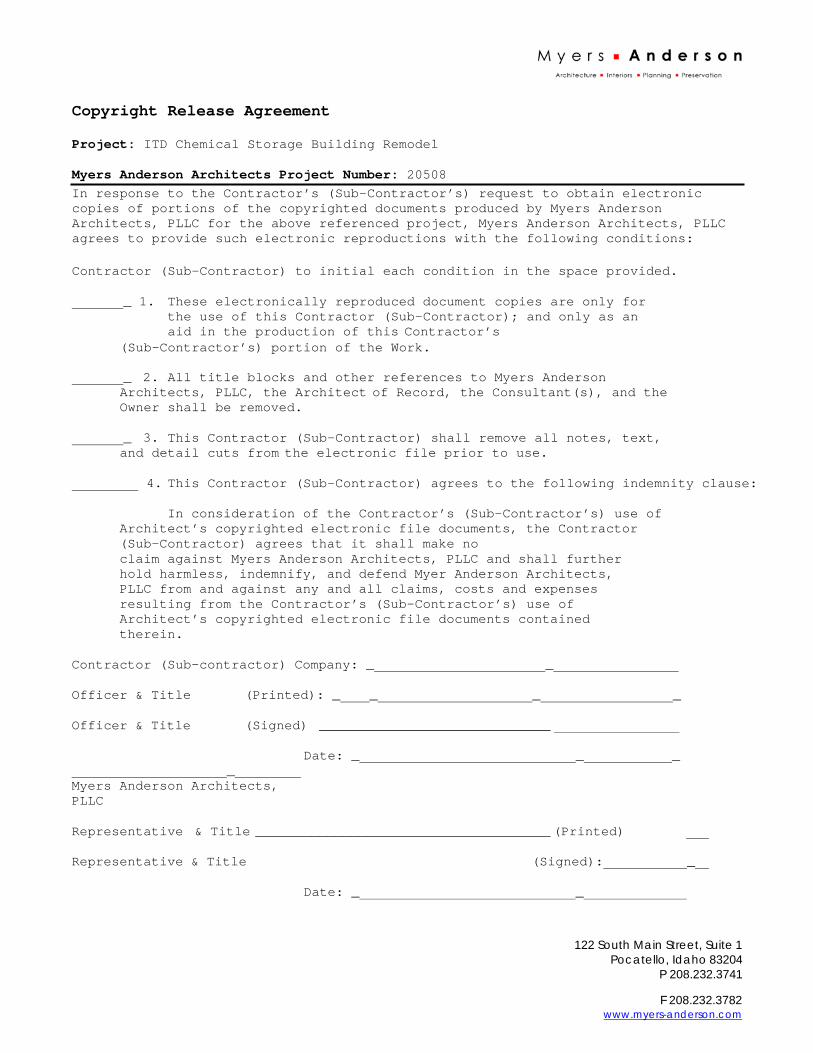
F 208.232.3782 www.myers-anderson.com
Copyright Release Agreement
Project: ITD Chemical Storage Building Remodel
Myers Anderson Architects Project Number: 20508
In response to the Contractor’s (Sub-Contractor’s) request to obtain electronic copies of portions of the copyrighted documents produced by Myers Anderson Architects, PLLC for the above referenced project, Myers Anderson Architects, PLLC agrees to provide such electronic reproductions with the following conditions:
Contractor (Sub-Contractor) to initial each condition in the space provided.
_ 1. These electronically reproduced document copies are only for the use of this Contractor (Sub-Contractor); and only as an aid in the production of this Contractor’s
(Sub-Contractor’s) portion of the Work.
_ 2. All title blocks and other references to Myers Anderson Architects, PLLC, the Architect of Record, the Consultant(s), and the Owner shall be removed.
_ 3. This Contractor (Sub-Contractor) shall remove all notes, text, and detail cuts from the electronic file prior to use.
4. This Contractor (Sub-Contractor) agrees to the following indemnity clause:
In consideration of the Contractor’s (Sub-Contractor’s) use of Architect’s copyrighted electronic file documents, the Contractor (Sub-Contractor) agrees that it shall make no claim against Myers Anderson Architects, PLLC and shall further hold harmless, indemnify, and defend Myer Anderson Architects, PLLC from and against any and all claims, costs and expenses resulting from the Contractor’s (Sub-Contractor’s) use of Architect’s copyrighted electronic file documents contained therein.
Contractor (Sub-contractor) Company: _ _
Officer & Title (Printed): _ _ _ _
Officer & Title (Signed) _____________________________
Date: _ _ _ _ Myers Anderson Architects, PLLC
Representative & Title _____________________________________ (Printed)
Representative & Title (Signed): _
Date: _ _
122 South Main Street, Suite 1 Pocatello, Idaho 83204
P 208.232.3741
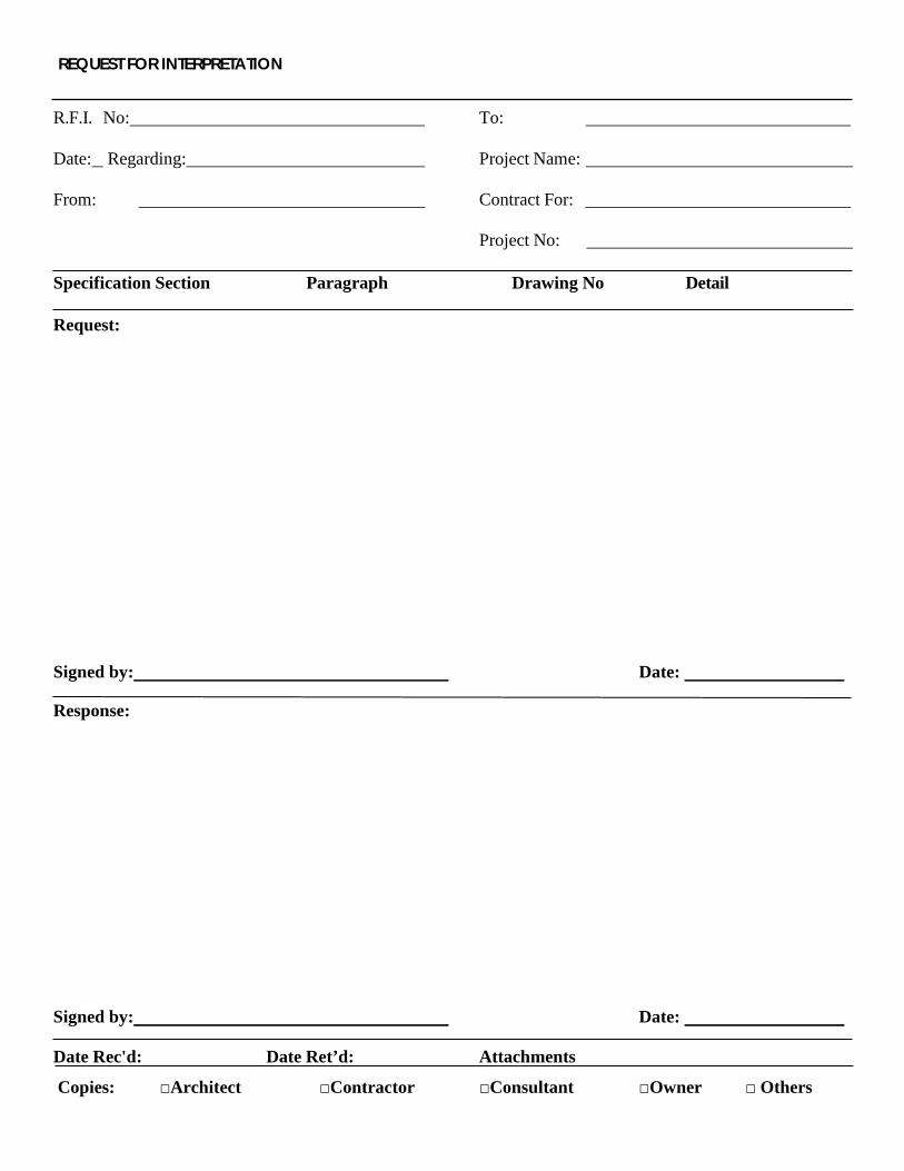
REQUEST FOR INTERPRETATION
R.F.I. No:
Date: Regarding:
From:
To:
Project Name:
Contract For:
Project No:
Specification Section Paragraph Drawing No Detail
Request:
Signed by: Date:
Response:
Signed by: Date:
Date Rec'd: Date Ret’d: Attachments
Copies: □Architect □Contractor □Consultant □Owner □ Others

□
SUBSTITUTION REQUEST (During the Bidding Phase)
Project:
To:
Re:
Substitution Request Number:
From:
Date:
A/E Project Number:
Contract For:
Specification Title: Description:
Section: Page: Article/Paragraph:
Proposed Substitution:
Manufacturer: Address: Phone:
Trade Name: Model No.: Attached data includes product description, specifications, drawings, photographs, and performance and test data adequate for evaluation of the request; applicable portions of the data are clearly identified.
Attached data also includes a description of changes to the Contract Documents that the proposed substitution will require for its proper installation.
The Undersigned certifies:
• Proposed substitution has been fully investigated and determined to be equal or superior in all respects to specified product. • Same warranty will be furnished for proposed substitution as for specified product. • Same maintenance service and source of replacement parts, as applicable, is available. • Proposed substitution will have no adverse effect on other trades and will not affect or delay progress schedule. • Proposed substitution does not affect dimensions and functional clearances. • Payment will be made for changes to building design, including A/E design, detailing, and construction costs caused by the substitution.
Submitted by:
Signed by:
Firm:
Address:
Telephone:
A/E’s REVIEW AND ACTION
Substitution approved - Make submittals in accordance with Specification Section 01 33 00.
Substitution approved as noted - Make submittals in accordance with Specification Section 01 33 00.
Substitution rejected - Use specified materials.
Substitution Request received too late - Use specified materials.
Signed by: Date:
Supporting Data Attached □ Drawings □Product Data □ Samples □ Tests □Reports □
Page 1 of 1
□ □ □
ITD Chemical Storage Building
02 41 19
DIVISION 2 EXISTING CONDITIONS
SECTION 02 41 19
SELECTIVE STRUCTURE DEMOLITION
PART 1 GENERAL
1.1 SUMMARY A. Section Includes:
1. Demolishing designated building equipment and fixtures. 2. Demolishing designated construction. 3. Cutting and alterations for completion of the Work. 4. Removing designated items for reuse and Owner’s retention. 5. Protecting items designated to remain. 6. Removing demolished materials.
1.2 SUBMITTALS
A. Section 01 33 00 - Submittal Procedures: Requirements for submittals. B. Demolition Schedule: Indicate overall schedule and interruptions required for
utility and building services. C. Shop Drawings:
1. Indicate demolition and removal sequence. 2. Indicate location of items designated for reuse and Owner’s retention. 3. Indicate location and construction of temporary work.
1.3 CLOSEOUT SUBMITTALS
A. Section 01 70 00 - Execution and Closeout Requirements: Requirements for submittals.
B. Project Record Documents: Accurately record actual locations of capped utilities, concealed utilities discovered during demolition, and subsurface obstructions.
1.4 QUALITY ASSURANCE
A. Conform to applicable code for demolition work, dust control, products requiring electrical disconnection and re-connection.
B. Conform to applicable code for procedures when hazardous or contaminated materials are discovered.
C. Obtain required permits from authorities having jurisdiction.
1.5 PRE-INSTALLATION MEETINGS A. Section 01 30 00 - Administrative Requirements: Pre-installation meeting. B. Convene minimum one week prior to commencing work of this section.
1.6 SEQUENCING
A. Section 01 10 00 - Summary: Requirements for sequencing.

ITD Chemical Storage Building
02 41 19
B. Owner will conduct salvage operations before demolition begins to remove materials Owner chooses to retain.
1.7 SCHEDULING A. Section 01 30 00 - Administrative Requirements: Requirements for scheduling.
B. Schedule Work to coincide with new construction. C. Cooperate with Owner in scheduling noisy operations and waste removal
that may impact Owners operation and in adjoining spaces. D. Perform noisy work:
1. Between hours of 8:00 am and 5:00 pm. 2. On following days: Monday through Saturday.
E. Coordinate utility and building service interruptions with Owner. 1. Do not disable or disrupt building fire or life safety systems without
three days prior written notice to Owner. 2. Schedule tie-ins to existing systems to minimize disruption. 3. Coordinate Work to ensure fire sprinklers, fire alarms, smoke
detectors, emergency lighting, exit signs and other life safety systems remain in full operation in occupied areas.
1.8 PROJECT CONDITIONS
A. Conduct demolition to minimize interference with adjacent and occupied building areas.
B. Cease operations immediately if structure appears to be in danger and notify Architect/Engineer. Do not resume operations until directed.
PART 2 PRODUCTS Not Used.
PART 3 EXECUTION
3.1 PREPARATION A. Notify affected utility companies before starting work and comply with their
requirements. B. Mark location and termination of utilities. C. Erect, and maintain temporary barriers and security devices, including warning
signs and lights, and similar measures, for protection of the public, Owner, and existing improvements indicated to remain.
D. Erect and maintain weatherproof closures for exterior openings. E. Erect and maintain temporary partitions to prevent spread of dust, odors, and
noise to permit continued Owner occupancy. F. Prevent movement of structure; provide temporary bracing and shoring
required to ensure safety of existing structure. G. Provide appropriate temporary signage including signage for exit or building egress. H. Do not close or obstruct building egress path.
ITD Chemical Storage Building
02 41 19
I. Do not disable or disrupt building fire or life safety systems without 3 days prior written notice to Owner.
3.2 SALVAGE REQUIREMENTS
A. Coordinate with Owner to identify building components and equipment required to be removed and delivered to Owner.
B. Tag components and equipment Owner designates for salvage. C. Protect designated salvage items from demolition operations until items
can be removed. D. Carefully remove building components and equipment indicated to be salvaged. E. Disassemble as required to permit removal from building. F. Package small and loose parts to avoid loss. G. Mark equipment and packaged parts to permit identification and
consolidation of components of each salvaged item. H. Prepare assembly instructions consistent with disassembled parts. Package
assembly instructions in protective envelope and securely attach to each disassembled salvaged item.
I. Deliver salvaged items to Owner. Obtain signed receipt from Owner.
3.3 DEMOLITION A. Conduct demolition to minimize interference with adjacent and occupied building
areas. B. Maintain protected egress from and access to adjacent existing buildings at all times. C. Do not close or obstruct roadways and sidewalks without permits. D. Cease operations immediately when structure appears to be in danger
and notify Architect. E. Disconnect and remove designated utilities within demolition areas. F. Cap and identify abandoned utilities at termination points when utility is not
completely removed. Annotate Record Drawings indicating location and type of service for capped utilities remaining after demolition.
G. Demolish in orderly and careful manner. Protect existing improvements, supporting structural members.
H. Carefully remove building components indicated to be reused. 1. Disassemble components as required to permit removal. 2. Package small and loose parts to avoid loss. 3. Mark components and packaged parts to permit reinstallation. 4. Store components, protected from construction operations, until reinstalled.
I. Remove demolished materials from site except where specifically noted otherwise. Do not burn or bury materials on site.
J. Remove materials as Work progresses. Upon completion of Work, leave areas in clean condition.
K. Remove temporary Work. L. Patch back and repair any existing surfaces called out to remain as if
ITD Chemical Storage Building
02 41 19
damaged during demolition. M. Patch back and tie into existing surfaces to match adjacent surfaces.
END OF DIVISION
ITD Chemical Storage Building
05 12 00
DIVISON 5 METALS
SECTION 05 12 00 STRUCTURAL
STEEL FRAMING
PART 1 GENERAL
1.1 SUMMARY A. Section Includes:
1. Structural shapes. 2. Channels and angles. 3. Hollow structural sections. 4. Structural plates and bars. 5. Fasteners, connectors, and anchors. 6. Grout.
B. Related Sections: 1. Section 05 50 00 - Metal Fabrications: Steel fabrications affecting
structural steel work.
1.2 REFERENCES A. American Institute of Steel Construction:
1. AISC 303 - Code of Standard Practice for Steel Buildings and Bridges. 2. AISC 341 - Seismic Provisions for Structural Steel Buildings. 3. AISC 360 - Specification for Structural Steel Buildings.
B. ASTM International: 1. ASTM A36/A36M - Standard Specification for Carbon Structural Steel. 2. ASTM A108 - Standard Specification for Steel Bar, Carbon and
Alloy, Cold- Finished. 3. ASTM A325 - Standard Specification for Structural Bolts, Steel, Heat
Treated, 120/105 ksi Minimum Tensile Strength. 4. ASTM A992/A992M - Standard Specification for Structural Steel Shapes. 5. ASTM F1554 - Standard Specification for Anchor Bolts, Steel, 36, 55,
and 105- ksi Yield Strength. C. American Welding Society:
1. AWS A2.4 - Standard Symbols for Welding, Brazing, and Nondestructive Examination.
2. AWS D1.1 - Structural Welding Code - Steel. D. Research Council on Structural Connections:
1. RCSC - Specification for Structural Joints Using ASTM A325 or ASTM A490 Bolts.
E. SSPC: The Society for Protective Coatings: 1. SSPC - Steel Structures Painting Manual. 2. SSPC Paint 20 - Zinc-Rich Primers (Type I - Inorganic and Type II - Organic). 3. SSPC SP 3 - Power Tool Cleaning.
1.3 SUBMITTALS
A. Section 01 33 00 - Submittal Procedures: Requirements for submittals. B. Shop Drawings:

ITD Chemical Storage Building
05 12 00
1. Indicate profiles, sizes, spacing, and locations of structural members, openings, attachments, and fasteners.
2. Connections and Connections not detailed. 3. Cambers and loads. 4. Indicate welded connections with AWS A2.4 welding symbols. Indicate
net weld lengths. C. Manufacturer's Mill Certificate: Certify products meet or exceed specified
requirements. D. Welders Certificates: Certify welders employed on the Work, verifying AWS
qualification within previous 12 months.
1.4 QUALITY ASSURANCE A. Perform Work in accordance with the following:
1. Structural Steel: Applicable AISC Specifications. 2. High Strength Bolted Connections: RCSC Specification for Structural
Joints Using ASTM A 325 or A 490 Bolts.
1.5 QUALIFICATIONS A. Fabricator: Company specializing in performing Work of this section with
minimum ten years documented experience B. Erector: Company specializing in performing Work of this section with
minimum ten years documented experience C. Shop Painter: Company specializing in performing Work of this section with
minimum ten years documented experience D. Welders and Welding Procedures: AWS D1.1 qualified within previous 12 months.
1.6 COORDINATION
A. Section 01 30 00 - Administrative Requirements: Requirements for coordination.
PART 2 PRODUCTS
2.1 STRUCTURAL STEEL A. Structural W-Shapes: ASTM A992 B. Structural M-Shapes: ASTM A36. C. Structural T-Shapes: Cut from structural W-shapes. D. Channels and Angles: ASTM A36 E. Square and Rectangular Hollow Structural Sections: ASTM A500/A500M, Grade B. F. Structural Plates and Bars: ASTM A36/A36M. Floor Plates: ASTM A786/A786M.
2.2 FASTENERS, CONNECTORS, AND ANCHORS
A. Bolts: ASTM A307: Grade A or B. 1. Finish: Unfinished.
B. High Strength Bolts: ASTM A325; Type 1. 1. Finish: Unfinished.

ITD Chemical Storage Building
05 12 00
C. Nuts: ASTM A563 heavy hex type. 1. Finish: Unfinished.
D. Washers: ASTM F436; Type 1, circular. 1. Finish: Unfinished.
2.3 WELDING MATERIALS A. Welding Materials: AWS D1.1; type required for materials being welded.
2.4 ACCESSORIES
A. Grout: Non-shrink type, as specified in Section 03 60 00. B. Shop Primer: SSPC Paint 15, Type 1, red oxide. C. Touch-Up Primer: Match shop primer.
2.5 FABRICATION
A. Continuously seal joined members by continuous welds. Grind exposed welds smooth.
B. Fabricate connections for bolt, nut, and washer connectors. C. Develop required camber for members.
2.6 FINISH
A. Prepare structural component surfaces in accordance with SSPC SP 3. B. Shop prime structural steel members. Do not prime surfaces that will be field
welded or in contact with concrete, Galvanizing for Fasteners, Connectors, and Anchors: 1. Hot-Dipped Galvanizing: ASTM A153/A153M. 2. Mechanical Galvanizing: ASTM B695; Class 50 minimum.
2.7 SOURCE QUALITY CONTROL AND TESTS
A. Section 01 40 00 - Quality Requirements: Testing, inspection and analysis requirements.
B. Shop test bolted and welded connections as specified for field quality control tests.
PART 3 EXECUTION
3.1 EXAMINATION A. Section 01 30 00 - Administrative Requirements: Verification of existing
conditions before starting work. B. Verify bearing surfaces are at correct elevation. C. Verify anchors rods are set in correct locations and arrangements with correct
exposure for steel attachment.
3.2 PREPARATION A. Furnish templates for installation of anchor rods and embedments in
concrete and masonry work.
ITD Chemical Storage Building
05 12 00
3.3 ERECTION
A. Allow for erection loads, and for sufficient temporary bracing to maintain structure safe, plumb, and in alignment until completion of erection and installation of permanent bracing.
B. Field weld components and shear connectors indicated on Drawings. C. Field connect members with threaded fasteners; torque to required resistance. D. Do not field cut or alter structural members without approval of Architect/Engineer. E. After erection, touch up welds and abrasions to match shop finishes.
3.4 GROUT INSTALLATION A. Grout under base plates in accordance with Section 03 60 00. B. Fill void under bearing surface with grout. Install and pack grout to remove air
pockets. C. Moist cure grout. D. Remove forms after grout is set. Trim grout edges to from smooth surface,
splayed 45 degrees. E. Tighten anchor bolts after grout has cured for a minimum of 3 days.
3.5 ERECTION TOLERANCES
A. Section 01 40 00 - Quality Requirements: Tolerances. B. Maximum Variation From Plumb: 1/4 inch per story, non-cumulative. C. Maximum Offset From Alignment: 1/4 inch.
3.6 FIELD QUALITY CONTROL
A. Section 01 40 00 - Quality Requirements: Field inspecting, testing, adjusting, and balancing.
B. Bolted Connections: Inspect in accordance with AISC 303. 1. Visually inspect all bolted connections. 2. For Direct Tension Indicators, comply with requirements of ASTM
F959. Verify that gaps are less than gaps specified in Table 2. C. Welding: Inspect welds in accordance with AWS D1.1.
1. Certify welders and conduct inspections and tests as required. Record types and locations of defects found in work. Record work required and performed to correct deficiencies.
2. Visually inspect all welds. 3. Ultrasonic Inspection: ASTM E164; perform on all full penetration welds. 4. Liquid Penetrate Inspection: ASTM E165. 5. Magnetic Particle Inspection: ASTM E709; performed on elements as
indicated on structural drawings. 6. Radiographic Inspection: ASTM E94; performed on as indicated on
structural drawings. D. Correct defective bolted connections and welds.
END OF SECTION
ITD Chemical Storage Building
05 50 00
SECTION 05 50 00
METAL FABRICATIONS
PART 1 GENERAL
1.1 SUMMARY A. Section includes shop fabricated metal items. B. Related Sections:
1. Section 05 12 00 - Structural Steel Framing: Structural steel anchor bolts.
1.2 REFERENCES A. ASTM International:
1. ASTM A36/A36M - Standard Specification for Carbon Structural Steel. 2. ASTM A53/A53M - Standard Specification for Pipe, Steel, Black and Hot-
Dipped, Zinc-Coated, Welded and Seamless. 3. ASTM A276 - Standard Specification for Stainless Steel Bars and Shapes. 4. ASTM A307 - Standard Specification for Carbon Steel Bolts and Studs,
60 000 PSI Tensile Strength. 5. ASTM A500/A500M - Standard Specification for Cold-Formed
Welded and Seamless Carbon Steel Structural Tubing in Rounds and Shapes.
6. ASTM A501 - Standard Specification for Hot-Formed Welded and Seamless Carbon Steel Structural Tubing.
7. ASTM A563 - Standard Specification for Carbon and Alloy Steel Nuts. 8. ASTM B695 - Standard Specification for Coatings of Zinc
Mechanically Deposited on Iron and Steel. 9. ASTM F436 - Standard Specification for Hardened Steel Washers. 10. ASTM F1554 - Standard Specification for Anchor Bolts, Steel, 36, 55,
and 105- ksi Yield Strength. B. American Welding Society:
1. AWS A2.4 - Standard Symbols for Welding, Brazing, and Nondestructive Examination.
2. AWS D1.1 - Structural Welding Code - Steel. C. National Ornamental & Miscellaneous Metals Association:
1. NOMMA Guideline 1 - Joint Finishes. D. SSPC: The Society for Protective Coatings:
1. SSPC - Steel Structures Painting Manual.
1.3 SUBMITTALS A. Section 01 33 00 - Submittal Procedures: Submittal requirements. B. Shop Drawings: Indicate profiles, sizes, connection attachments, reinforcing,
anchorage, size and type of fasteners, and accessories. Include erection drawings, elevations, and details where applicable. Indicate welded connections using standard AWS A2.0 welding symbols. Indicate net weld lengths.
C. Welders Certificates: Certify welders employed on the Work, verifying AWS qualification within previous 12 months.

ITD Chemical Storage Building
05 50 00
1.4 QUALITY ASSURANCE
A. Finish joints in accordance with NOMMA Guideline 1.
1.5 QUALIFICATIONS A. Design under direct supervision of Professional Engineer experienced in
design of this Work and licensed at Project location.
1.6 DELIVERY, STORAGE, AND HANDLING A. Section 01 60 00 - Product Requirements: Product storage and handling
requirements. B. Accept metal fabrications on site in labeled shipments. Inspect for damage. C. Protect metal fabrications from damage by exposure to weather.
1.7 FIELD MEASUREMENTS
A. Verify field measurements are as indicated drawings.
PART 2 PRODUCTS
2.1 MATERIALS - STEEL A. Structural Shapes: STM A36/A36M. B. Steel Plate: ASTM A36/A36M. C. Hollow Structural Sections: ASTM A500/A500M, Grade B. D. Sheet Steel: ASTM A653/A653M, Grade 33 Structural Quality. E. Bolts: ASTM A325; Type 1.
1. Finish: Mechanically galvanized. F. Nuts: ASTM A563 heavy hex type.
1. Finish: Mechanically galvanized. G. Washers: ASTM F436; Type 1.
1. Finish: Mechanically galvanized. H. Welding Materials: AWS D1.1; type required for materials being welded. I. Shop Primer: SSPC Paint 15, Type 1, red oxide. J. Touch-Up Primer: Match shop primer.
2.2 STRUCTURAL SUPPORTS
A. Other Structural Supports: Steel sections, shape and size as indicated on Drawings ; prime paint, one coat .
2.3 DOOR FRAMES
A. Door Frames: Steel channel sections, size indicated on Drawings, with jamb
anchors suitable for building into masonry, attachment to concrete, and, minimum 4 anchors per jamb; prime paint, one coat

ITD Chemical Storage Building
05 50 00
2.4 BOLLARDS
A. Bollards: Steel pipe, concrete filled, crowned cap, 6 in diameter, length as indicated on Drawings; prime paint, one coat
B. Concrete Fill: 3,000 psi as specified in Section 03 30 00 - Cast-in-Place Concrete
C. Anchors: Concealed type as indicated on Drawings
2.5 FABRICATED ARCHITECTURAL TRIM
A. Steel sections, size and configuration as indicated on Drawings
B. Exterior Locations: Prime paint, one coat
2.6 ANCHORS
A. Anchor Rods: ASTM A307; Grade A 1. Shape: Hooked and Straight 2. Furnish with nut and washer; unfinished
B. Epoxy Adhesive Anchors:
1. Manufacturer List: a. Cobra Anchors b. Hilti, Inc c. Simpson Strong-Tie Co., Inc d. Substitutions: Section 01 60 00 - Product Requirements
C. Grout: According to Section 03 60 00 - Grouting
D. Threaded Rod: As shown on the drawings or as approved by Architect
2.7 ANCHOR BOLTS
A. Anchor Rods: ASTM F1554; Grade 55, wieldable. 1. Shape: Hooked. 2. Furnish with nut and washer; unfinished.
2.8 FABRICATION
A. Fit and shop assemble items in largest practical sections, for delivery to site. B. Fabricate items with joints tightly fitted and secured. C. Continuously seal joined members by continuous welds. D. Grind exposed joints flush and smooth with adjacent finish surface. Make
exposed joints butt tight, flush, and hairline. Ease exposed edges to small uniform radius.
E. Exposed Mechanical Fastenings: Flush countersunk screws or bolts; unobtrusively located; consistent with design of component, except where specifically noted otherwise.
F. Supply components required for anchorage of fabrications. Fabricate anchors and related components of same material and finish as fabrication, except where specifically noted otherwise.
ITD Chemical Storage Building
05 50 00
2.9 FACTORY APPLIED FINISHES - STEEL A. Clean surfaces of rust, scale, grease, and foreign matter prior to finishing. B. Do not prime surfaces in direct contact with concrete or where field welding is
required. C. Prime paint items with two coats except where galvanizing is specified. D. Galvanizing: ASTM A123/A123M; hot dip galvanize after fabrication. E. Chrome Plating: ASTM B177, weight, nickel-chromium alloy, polished finish.
2.10 FABRICATION TOLERANCES
A. Squareness: 1/8 inch maximum difference in diagonal measurements. B. Maximum Offset Between Faces: 1/16 inch.
C. Maximum Misalignment of Adjacent Members: 1/16 inch. D. Maximum Bow: 1/8 inch in 48 inches. E. Maximum Deviation From Plane: 1/16 inch in 48 inches.
PART 3 EXECUTION
3.1 EXAMINATION A. Section 01 30 00 - Administrative Requirements: Coordination and project conditions. B. Verify field conditions are acceptable and are ready to receive Work.
3.2 PREPARATION
A. Clean and strip primed steel items to bare metal and aluminum where site welding is required.
B. Supply steel items required to be cast into concrete or embedded in masonry with setting templates to appropriate sections.
3.3 INSTALLATION
A. Install items plumb and level, accurately fitted, free from distortion or defects. B. Make provisions for erection stresses. Install temporary bracing to maintain
alignment, until permanent bracing and attachments are installed. C. Field weld components indicated on Drawings. D. Perform field welding in accordance with AWS D1.1. E. Obtain approval of Architect/Engineer prior to site cutting or making
adjustments not scheduled. F. After erection, touch up welds, abrasions, and damaged finishes with prime
paint or galvanizing repair paint to match shop finishes.
3.4 ERECTION TOLERANCES A. Section 01 40 00 - Quality Requirements: Tolerances. B. Maximum Variation From Plumb: 1/4 inch per story or for every 12 ft in height
ITD Chemical Storage Building
05 50 00
whichever is greater, non-cumulative. C. Maximum Offset From Alignment: 1/4 inch. D. Maximum Out-of-Position: 1/4 inch.
3.5 FIELD QUALITY CONTROL
A. Welding: Inspect welds in accordance with AWS D1.1.
END OF DIVISION
ITD Chemical Storage Building
06 10 00
DIVISION 6 WOOD, PLASTICS, AND COMPOSITES
SECTION 06 10 00
ROUGH CARPENTRY
PART 1 GENERAL
1.1 SUMMARY A. Section includes structural wall and roof framing; built-up structural beams and
columns; wall, and roof sheathing; sill gaskets; and miscellaneous framing and sheathing.
B. Related Sections: 1. Section 06 10 53: Miscellaneous Rough Carpentry.
1.2 REFERENCES
A. American National Standards Institute: 1. ANSI A135.4 - Basic Hardboard. 2. ANSI A208.1 - Mat-Formed Wood Particleboard.
B. American Wood-Preservers’ Association: 1. AWPA M4 - Standard for the Care of Preservative-Treated Wood Products.
C. AWPA ASTM International: 1. ASTM A153/A153M - Standard Specification for Zinc Coating (Hot-Dip)
on Iron and Steel Hardware. 2. ASTM F1667 - Standard Specification for Driven Fasteners: Nails,
Spikes, and Staples. D. The Redwood Inspection Service:
1. RIS - Standard Specifications for Grades of California Redwood Lumber. E. Southern Pine Inspection Bureau:
1. SPIB - Standard Grading Rules for Southern Pine Lumber. F. U.S. Department of Commerce National Institute of Standards and Technology:
1. DOC PS 1 - Construction and Industrial Plywood. 2. DOC PS 2 - Performance Standard for Wood-Based Structural-Use Panels. 3. DOC PS 20 - American Softwood Lumber Standard.
G. West Coast Lumber Inspection Bureau: 1. WCLIB - Standard Grading Rules for West Coast Lumber.
H. Western Wood Products Association: 1. WWPA G-5 - Western Lumber Grading Rules.
1.3 QUALITY ASSURANCE
A. Perform Work in accordance with the following: 1. Lumber Grading Agency: Certified by DOC PS 20. 2. Lumber: DOC PS 2 Apply label from agency approved by authority
having jurisdiction to identify each preservative treated material.
1.4 DELIVERY, STORAGE, AND HANDLING A. Section 01 60 00 - Product Requirements: Product storage and handling
requirements.
ITD Chemical Storage Building
06 10 00
B. Protect trusses from warping or other distortion by stacking in vertical position, braced to resist movement.
PART 2 PRODUCTS
2.1 LUMBER MATERIALS A. Lumber Grading Rules: NLGA RIS SPIB WCLIB WWPA or NELMA. B. Beam Framing: Douglas Fir - Larch grade, No 2 or better, 19 percent maximum
moisture content. C. Parallel Strand Lumber (PSL) – Weyerhaeuser 2.0E Parallam. D. Joist Framing: Douglas Fir - Larch grade, No 2 or better, 19 percent maximum
moisture content. E. Non-structural Light Framing: Douglas Fir - Larch grade, No 2 or better, 19
percent maximum moisture content. F. Studding: Douglas Fir - Larch grade, No 2 or better, 19 percent maximum
moisture content. G. Miscellaneous Framing: Douglas Fir - Larch grade, No 2 or better, 19 percent
maximum moisture content, pressure preservative treat where required by code.
2.2 SHEATHING MATERIALS A. Wood Structural Panel Roof Sheathing: EWA Rated Sheathing; Plywood
Oriented Strand Board Span Rating as noted on structural drawings; Exposure Durability 1 exterior; unsanded.
B. Particleboard Roof Sheathing: ANSI A208.1 Waferboard Structural Particleboard; wood chips shavings flakes set with waterproof resin binder; grade as noted on structural drawings; unsanded faces.
C. Wood Structural Panel Wall Sheathing: EWA Rated Sheathing, Plywood Oriented Strand Board; Span Rating as noted on structural drawings; Exposure Durability 1 Exterior; unsanded.
D. Particleboard Wall Sheathing: ANSI A208.1 EWA Waferboard Structural Particleboard; wood chips, shavings, and flakes set with waterproof resin binder; grade as noted on structural drawings; unsanded faces.
2.3 SHEATHING AND UNDERLAYMENT LOCATIONS
A. Sloped Roof Sheathing: 19/32 inches thick; Span Rating: 40/20; 48 x 96 inch sized sheets, square edges.
B. Wall Sheathing: 7/16 inch thick, Span Rating 32/16, 48 x 96 inch sized sheets,
square edges.
C. Floor Sheathing: 3/4 inch thick, Span Rating 40/20, 48 x 96 inch sized sheets, square edges.
D. Underlayment: 3/8 inch thick, type recommended by flooring manufacturer
2.4 FIREBLOCKING AND DRAFTSTOPPING
ITD Chemical Storage Building
06 10 00
A. Fireblocking: Solid lumber, structural wood panel, or particleboard. 1. Solid lumber nominal 2 inches thick. 2. Two layers of solid lumber nominal 1 inch thick with broken lapped joints. 3. Structural wood panel 23/32 inch thick with joints backed by
structural wood panel. 4. Particleboard 3/4 inch thick with joints backed by particleboard.
2.5 ACCESSORIES A. Fasteners and Anchors:
1. Fasteners: ASTM A153/A153M, hot dipped galvanized steel for high humidity and treated wood locations, unfinished steel elsewhere.
2. Nails and Staples: ASTM F1667. 3. Drywall Screws: Bugle head, hardened steel, power driven type,
length to achieve full penetration of sheathing substrate. 4. Anchors: Toggle bolt type for anchorage to hollow masonry. Expansion
shield and lag bolt type for anchorage to solid masonry or concrete. Bolt or ballistic fastener for anchorages to steel.
B. Die Stamped Connectors: inch thick, hot dipped galvanized steel. C. Structural Framing Connectors: Hot dipped galvanized steel, sized to suit
framing conditions. D. Sill Gasket on Top of Foundation Wall: 1/4 inch thick, plate width, glass fiber strip. E. Subfloor Glue: EWA AFG-01, waterproof of water base, air cure type, and
cartridge dispensed. F. Building Paper: ASTM D226; Type I, No. 15 unperforated asphalt felt.
PART 3 EXECUTION
3.1 FRAMING A. Set structural members level and plumb, in correct position. B. Make provisions for erection loads, for sufficient temporary bracing to maintain
structure safe, plumb, and in alignment until completion of erection and installation of permanent bracing.
C. Place horizontal members, crown side up. D. Construct load bearing framing and curb members full length without splices. E. Double members at openings over inches wide. Space short studs over
and under opening to stud spacing. F. Construct double joist headers at floor and ceiling openings and under
wall stud partitions parallel to floor joists. Frame rigidly into joists. G. Bridge joists at mid-span. Fit solid blocking at ends of members. H. Place sill gasket directly on cementitious foundation. Puncture gasket clean and
fit tight to protruding foundation anchor bolts. I. Coordinate installation of glue laminated structural units, prefabricated wood
trusses, and wood “I” joists. J. Coordinate curb installation with installation of roof sheathing roofing

ITD Chemical Storage Building
06 10 00
and vapor retardant.
3.2 SHEATHING A. Secure roof sheathing with longer edge (strength axis) perpendicular to
framing members and with ends staggered and sheet ends over bearing. B. Use sheathing clips between sheets between roof framing members. Install
solid edge blocking between sheets.
C. Secure wall sheathing with long dimension perpendicular to wall studs, with ends over firm bearing and staggered. Place building air barrier over wall sheathing; weather lap edges and ends.
D. Install plywood to simple span.
3.3 FIREBLOCKING AND DRAFTSTOPPING A. Install fireblocking to cut off concealed draft openings.
1. Concealed Framed Wall and Furred Spaces: Install fireblocking vertically at floor and ceiling levels and horizontally at maximum 10 feet on center.
2. Connections Between Horizontal and Vertical Spaces: Install fireblocking between vertical walls and partitions and the following: a. Horizontal roof framing. b. Soffits, dropped ceilings, cove ceilings and other horizontal
concealed spaces. 3. Exterior Combustible Architectural Trim: Install fireblocking at maximum
20 feet on center
3.4 TOLERANCES A. Section 01 40 00 - Quality Requirements: Tolerances B. Framing Members: 1/4 inch from indicated position, maximum. C. Surface Flatness of Floor: 1/4 inch in 10 feet maximum, and 1/2 inch in
30 feet maximum.
END OF SECTION
ITD Chemical Storage Building
06 10 53
SECTION 06 10 53
MISCELLANEOUS ROUGH CARPENTRY
PART 1 GENERAL
1.1 SUMMARY A. Section includes roof curbs, and perimeter nailers; blocking in wall and roof
openings; wood furring and grounds; wall cabinets, wood trim; telephone and electrical panel back boards; and concealed wood blocking for support.
1.2 REFERENCES
A. American National Standards Institute: 1. ANSI A208.1 - Mat-Formed Wood Particleboard.
B. American Wood-Preservers’ Association: 1. AWPA M4 - Standard for the Care of Preservative-Treated Wood Products.
C. ASTM International: 1. ASTM A153/A153M - Standard Specification for Zinc Coating (Hot-Dip)
on Iron and Steel Hardware. 2. ASTM F1667 - Standard Specification for Driven Fasteners: Nails,
Spikes, and Staples. D. The Redwood Inspection Service:
1. RIS - Standard Specifications for Grades of California Redwood Lumber. E. Southern Pine Inspection Bureau:
1. SPIB - Standard Grading Rules for Southern Pine Lumber. F. U.S. Department of Commerce National Institute of Standards and Technology:
1. DOC PS 1 - Construction and Industrial Plywood. 2. DOC PS 20 - American Softwood Lumber Standard.
G. West Coast Lumber Inspection Bureau: 1. WCLIB - Standard Grading Rules for West Coast Lumber.
H. Western Wood Products Association: 1. WWPA G-5 - Western Lumber Grading Rules.
1.3 QUALITY ASSURANCE
A. Perform Work in accordance with the following: 1. Lumber Grading Agency: Certified by DOC PS 20. 2. Lumber: DOC PS 20.
PART 2 PRODUCTS
2.1 MATERIALS A. Lumber Grading Rules: NLGA RIS SPIB WCLIB WWPA or NELMA. B. Miscellaneous Framing: Douglas Fir - Larch grade, No 2 or better, 19 percent
maximum moisture content. C. Plywood: EWA Rated Sheathing; Plywood Oriented Strand Board Span Rating
as noted on structural drawings; Exposure Durability 1 exterior; unsanded.
ITD Chemical Storage Building
06 10 53
D. Particleboard: ANSI A208.1 Waferboard Structural Particleboard; wood chips shavings flakes set with waterproof resin binder; grade as noted on structural drawings; unsanded faces.
2.2 ACCESSORIES
A. Fasteners and Anchors: 1. Fasteners: ASTM A153/A153M, hot dipped galvanized steel for high
humidity and treated wood locations, unfinished steel elsewhere. 2. Nails and Staples: ASTM F1667. 3. Drywall Screws: Bugle head, hardened steel, power driven type,
length to achieve full penetration of sheathing substrate. 4. Anchors: Toggle bolt type for anchorage to hollow masonry. Expansion
shield and lag bolt type for anchorage to solid masonry or concrete. Bolt or ballistic fastener for anchorages to steel.
2.3 FACTORY WOOD TREATMENT
A. Wood Preservative (Pressure Treatment): AWPA U1, Commodity Specification A-Sawn Products or F-Wood Composites using water-borne preservative.
B. Wood Preservative (Surface Application): Clear, Fire Retardant Treatment: Chemically treated and pressure impregnated, having flame spread of 25 or less when tested in accordance with ASTM E 84 and showing no evidence of significant progressive combustion when test is continued for an additional 20 minute period, Interior Type.
C. Moisture Content after Treatment: Kiln dried (KDAT). 1. Lumber: Maximum 19 percent. 2. Structural Panels: Maximum 15 percent.
PART 3 EXECUTION
3.1 EXAMINATION A. Section 01 30 00 - Administrative Requirements: Verification of existing
conditions before starting work. B. Verify substrate conditions are ready to receive blocking, curbing and framing.
3.2 PREPARATION
A. Coordinate placement of blocking, curbing and framing items.
3.3 INSTALLATION A. Set members level and plumb, in correct position. B. Place horizontal members, crown side up. C. Construct curb members of solid wood sections. D. Curb roof openings except where prefabricated curbs are provided. Form
corners by alternating lapping side members. E. Coordinate curb installation with installation of decking and support of deck
openings, and roofing vapor retardant. F. Space framing and furring 16 inches oc.
ITD Chemical Storage Building
06 10 53
G. Secure sheathing to framing members with ends over firm bearing and staggered. H. Install telephone and electrical panel back boards with plywood sheathing
material where required. Size back boards 12 inches beyond size of electrical and telephone panel.
END OF SECTION
ITD Chemical Storage Building
06 41 00
SECTION 06 41 00
ARCHITECTURAL WOODWORK
PART 1 - GENERAL
1.1 SUMMARY
A. Section Includes: 1. Custom casework.
a. Plastic laminate finished casework. 2. Counter tops.
a. Plastic laminate finished counter tops. b. Synthetic surfacing counter tops c. Metal Finished Counter Tops
3. Cabinet hardware. B. Related Requirements:
1. Section 06 10 53 - Miscellaneous Rough Carpentry: Grounds and support framing.
1.2 REFERENCE STANDARDS
A. American National Standards Institute: 1. ANSI A135.4 - Basic Hardboard. 2. ANSI A156.9 - Cabinet Hardware.
B. APA - The Engineered Wood Association: 1. APA/EWA PS 1 - Voluntary Product Standard for Construction and Industrial Plywood.
C. Architectural Woodwork Institute, Woodwork Institute: 1. AWS - Architectural Woodwork Standards. 2. Supplemented with The WI Approach.
D. ASTM International: 1. ASTM A153 - Standard Specification for Zinc Coating (Hot-Dip) on Iron
and Steel Hardware. 2. ASTM D1037 - Standard Test Methods for Evaluating Properties of Wood
Base Fiber and Particle Panel Materials. 3. ASTM E84 - Standard Test Method for Surface Burning Characteristics of
Building Materials. 4. ASTM F1667 - Standard Specification for Driven Fasteners: Nails, Spikes, and
Staples. E. Hardwood Plywood and Veneer Association:
1. HPVA HP-1 - American National Standard for Hardwood and Decorative Plywood. F. National Electrical Manufacturers Association:
1. NEMA LD 3 - High-Pressure Decorative Laminates. G. National Fire Protection Association:
1. NFPA 286 - Standard Methods of Fire Tests for Evaluating Contribution of Wall and Ceiling Interior Finish to Room Fire Growth.
H. U.S. Department of Commerce National Institute of Standards and Technology: 1. DOC PS 20 - American Softwood Lumber Standard.
I. Western Red Cedar Association: 1. WRCA - Lumber Grades and Standards.
ITD Chemical Storage Building
06 41 00
J. Window and Door Manufacturers Association: 1. WDMA I.S.4 - Water-Repellent Treatment for Millwork.
1.3 SUBMITTALS
A. Section 01 33 00 - Submittal Procedures: Requirements for submittals, including AWS Section 1.
B. Product Data: Submit data on: 1. High-pressure decorative laminates. 2. Hardware accessories.
C. Shop Drawings:
1. Indicate materials, component profiles and elevations, assembly methods, joint details, fastening methods, accessory listings, hardware location, schedule of finishes, and Certified Compliance Label on each set.
D. Samples:
1. Submit two, 6 x 6 in samples, illustrating cabinet finish. 2. Submit two, 6 x 6 in samples, illustrating counter top finish.
E. Qualification Statements:
1. Submit qualifications for fabricator.
1.4 QUALITY ASSURANCE
A. Perform Work according to Architectural Woodwork Institute, Woodwork Institute; premium grade.
1.5 QUALIFICATIONS
A. Fabricator: Company specializing in fabricating products specified in this
Section with minimum five years' documented production experience similar to this Project.
1.6 DELIVERY, STORAGE, AND HANDLING
A. Section 01 60 00 - Product Requirements: Requirements for transporting, handling,
storing, and protecting products. B. Protect units from moisture damage.
1.7 AMBIENT CONDITIONS
A. Section 01 50 00 - Temporary Facilities and Controls: Requirements for ambient
conditions control facilities for product storage and installation. B. Maintain storage space relative humidity within ranges indicated in AWS Section 2. C. Subsequent Conditions: Maintain same temperature and humidity conditions in
building spaces as will occur after occupancy during and after installation of Work of this Section.
1.8 EXISTING CONDITIONS
A. Field Measurements: Verify field measurements prior to fabrication.
ITD Chemical Storage Building
06 41 00
Indicate field measurements on Shop Drawings.
PART 2 - PRODUCTS
2.1 CUSTOM CASEWORK A. Plastic-Laminate-Finished Custom Casework:
1. Face-framed construction. 2. Style: Flush overlay. 3. AWS Section 10. 4. Premium grade. 5. Exterior and Interior Exposed Surfaces: Compacted laminate panel. 6. Semi-Exposed Surfaces: Compacted laminate panel.
B. Casework Construction Details: 1. Drawer Side Joinery: Doweled. 2. Drawer and Door Edge Profile: Square with thin, applied vinyl band. 3. Toe Base Finish: As indicated on the drawings.
C. Plastic Laminate Finished Counter Tops: AWS Section 11; premium grade. 1. Core: Particleboard.
a. Core at Sink Tops: Exterior or exterior glue type panels. 2. Splash Top Profile: Square with scribe. 3. Deck at Splash Joint Type: Vertical butt. 4. Front Edge: Synthetic Surfacing. 5. Splash Assembly: Field assembled.
D. Synthetic Surfacing Counter Tops: AWS Section 11; premium grade. 1. Nominal sheet thickness: Indicated on Drawings. 2. Splash Top Profile: Square with scribe. 3. Deck at Splash Joint Type: Vertical butt. 4. Front Edge: Match counter top. 5. Splash Assembly: Field assembled.
E. Metal Finished Counter Tops
1. Nominal sheet thickness: 24 gauge sheet metal. 2. Core: ¾ inch Plywood or Particleboard.
a. Core at Sink Tops: Exterior or exterior glue type panels. 3. Splash Top Profile: Square with scribe. 4. Deck at Splash Joint Type: Vertical butt. 5. Front Edge: Hemmed edges sheet metal. 6. Splash Assembly: Field assembled.
2.2 INTERIOR FINISH CARPENTRY
A. Shelving: Softwood lumber.
1. Melamine Coated Particleboard Shelving. a. Edging: Applied Vinyl thin band b. Band Width: Match Shelf thickness
2.3 CASEWORK MATERIALS
A. Softwood Lumber: DOC PS 20; WI Custom maximum moisture content of 6-8 percent
1. Species: Douglas fir - Larch or Pine. 2. Cut: Plain sawn.
ITD Chemical Storage Building
06 41 00
B. Hardwood Lumber: DOC PS 20. WI Premium Grade; maximum moisture content of 6-8 percent. 1. Species:
a. Stained finish – Red Oak b. Painted finish - Poplar
2. Cut: Plain sawn. C. Softwood Plywood: APA/EWA PS 1 softwood plywood with lumber core and the following:
1. Grade: C-D 2. Face Veneer: Douglas Fir 3. Veneer Slicing: Rotary. 4. Matching of Individual Leaves to Each Other: Book matching. 5. Matching Across Panel Face: Center balanced matching. 6. Matching or Relationship of Panels to Each Other: Sequence-matched,
uniform-size sets matching. D. Hardwood Plywood: AWI Grade AA veneer; WI Premium veneer; with lumber core;
and the following: 1. Grade: A-A 2. Face Veneer: Red Oak 3. Veneer Slicing: Rotary. 4. Matching of Individual Leaves to Each Other: Book matching. 5. Matching Across Panel Face: Center balanced matching. 6. Matching or Relationship of Panels to Each Other: Sequence-matched,
uniform-size sets matching. E. Compacted Laminate Panel: Laboratory Grade, Double Faced, NEMA LD3-
2005, Grade CGS, Thickness as indicated on drawings F. Medium-Density Fiberboard: ANSI A208.2, composed of wood fibers, medium density. G. Medium-Density Overlay: APA/EWA PS 1; softwood plywood, exterior type, with
paper face suitable for opaque finish. H. Hardboard: AHA A135.4; pressed wood fiber with resin binder, tempered grade, 1/4
in thick, smooth one side. I. High-Pressure Decorative Laminate (HPDL): NEMA LD 3; color, pattern, and
surface texture as selected or as specified on Drawings. 1. Horizontal Surfaces: HGS; 0.048 in thick. 2. Vertical Surfaces: VGS; 0.028 in thick. 3. Cabinet Liner: CLS; 0.020 in thick. 4. Backing Sheet: BKL; 0.020 in thick.
J. Sheet Metal Components: Stainless steel, Type 304 with No. 4 satin finish; 20 gauge. K. Synthetic Surfacing: Synthetic marble of polyester or proprietary resins, with
integral color and design, stain resistant to domestic chemicals and cleaners. 1. Manufacturers
a. Wilsonart International. b. Gibraltar® Solid Surface. c. DuPont Company: Corian. d. Substitutions: Section 01 60 00 - Product Requirements.
2.4 FABRICATION
A. Fabricate casework to AWS Section 10 premium grade. B. Fabricate counter tops to AWS Section 11 premium grade.
ITD Chemical Storage Building
06 41 00
C. Shop-assemble casework for delivery to Site in units easily handled and to permit passage through building openings.
D. Fit exposed plywood edges with PVC plastic edging. Use one piece for full length only. E. Cap exposed high-pressure decorative laminate finish edges with PVC plastic trim. F. Door and Drawer Fronts: 3/4 in thick. G. When necessary to cut and fit on-Site, fabricate materials with ample allowance for
cutting. Furnish trim for scribing and Site cutting.
H. Apply high-pressure decorative laminate finish in full, uninterrupted sheets consistent with manufactured sizes. Fit corners and joints hairline; secure with concealed fasteners. Locate plastic laminate joints minimum 18 in from sink cutouts.
I. Apply laminate backing sheet to reverse side of plastic- laminate-finished surfaces where required by AWS for specified grade.
J. Fabricate metal counter top surfaces pressure glued to plywood or particle board core backing without visible joints.
K. Fabricate cabinets and counter tops with cutouts for plumbing fixtures, inserts, outlet boxes, fixtures, and fittings. Verify locations of cutouts from on-Site dimensions. Seal cut edges.
2.5 FINISHES
A. Sand Work smooth and set exposed nails and screws. B. Apply wood filler in exposed nail and screw indentations. C. On items to receive transparent finishes, use wood filler matching surrounding
surfaces and types recommended for applied finishes. D. Prime paint or seal surfaces in contact with cementitious materials. E. Finish according to Section 09 90 00 - Painting and Coating.
2.6 ACCESSORIES
A. Adhesive for High-Pressure Decorative Laminates: Type recommended by
laminate manufacturer to suit application. B. Fasteners and Anchors:
1. Fasteners: ASTM B695, Class 55 mechanically galvanized steel for high-humidity and treated wood locations, unfinished steel elsewhere.
2. Nails and Staples: ASTM F1667. C. Bolts, Nuts, Washers, Lags, Pins, and Screws: Of size and type to suit application;
chrome finish in concealed locations and chrome finish in exposed locations. D. Concealed Joint Fasteners: Threaded steel. E. Grommets: Plastic material for cut-outs.
1. Size: As shown on the drawings F. Plastic Edge Trim: AWS; standard PVC; color as selected. G. Glass: Type as specified in Section 08 80 00 - Glazing.
ITD Chemical Storage Building
06 41 00
2.7 HARDWARE
A. Cabinet Adjustable Shelf Supports: In-line bored holes 1-3/8 in o.c., to within 6 in of top and bottom of opening with four support pins for each shelf. 1. Vinyl coated steel, pin size 4.7 mm x 5/16”. 2. Quality Standard – Knape & Vogt 348
B. Shelf Standards and Rests: Formed steel channels and rests, cut for fitted rests spaced as shown on drawings; 1. Finish: as selected 2. Quality Standard – Knape & Vogt 255 and 256.
C. Shelf Brackets: Formed steel brackets, formed for attachment with lugs; 1. Size: As shown on the drawings. 2. Finish: Chrome. 3. Quality Standard – Knape & Vogt Super duty standard and brackets.
D. Drawer and Door Pulls: 1. Type: U-shaped pull. 2. Size and Spacing: 4 inch centers. 3. Finish: Solid stainless steel with satin finish.
E. Cabinet Locks: 1. Type: Pin tumbler type suitable for location. 2. Keying: Key locks separately. Stamp keys consecutively beginning with “1”.
Key to facility master key. 3. Quality Standard: Schlage CL-series.
F. Catches: 1. Plastic case, magnet type. 2. Quality Standard – Hafele 246.50.708.
G. Drawer Slides: Self-closing, galvanized steel construction, ball bearings separating tracks, rail mounted full extension type. 1. Load Rating: 100lb for standard drawers, 150lbs for lateral file. 2. Quality Standards –
a. Standard Drawers – Accuride 3832. b. Lateral Files – Accuride 4005.
H. Hinges: 1. European style, free swinging 2. Quality Standard – Grass 2-Dimensional Series.
I. Lockable LCD Display Support System with keyboard tray: 1. Quality Standard – CBT Supply Inc , Model: FlipIt
a. Dual Screen FIK -36 b. Single Screen FIK – 23
J. Counter Top Supports Brackets: Powdercoated 1008 Cold Rolled Steel. 1. Size 20 inches x 20 inches 2. Load Rating: 1000 pounds per a pair based 16 inches on center. 3. Quality Standard: Federal Brace 326
PART 3 - EXECUTION
3.1 EXAMINATION
ITD Chemical Storage Building
06 41 00
A. Section 01 70 00 - Execution and Closeout Requirements: Requirements for installation examination.
B. Verify adequacy of backing and support framing. C. Verify location and sizes of utility rough-in associated with Work of this Section.
3.2 PREPARATION
A. Section 01 70 00 - Execution and Closeout Requirements: Requirements for
installation preparation.
3.3 INSTALLATION
A. Install casework according to AWS Section 10 premium grade. B. Install counter tops according to AWS Section 11 premium grade. C. Caulk all joints between backsplash and counter top. Color to match counter top. D. Caulk all joints between backsplash, counter top and walls. Color to match counter top.
E. Set and secure casework, interior finish carpentry, and counter tops in place; rigid, plumb, and level.
F. Use fixture attachments in concealed locations for wall-mounted components. G. Use concealed joint fasteners to align and secure adjoining cabinet units and counter
tops. H. Carefully scribe casework abutting other components, with maximum gaps of
1/32 in. use additional overlay trim for this purpose. I. Secure woodwork cabinet and counter bases to floor using appropriate
angles and anchorages. J. Countersink anchorage devices at exposed locations. Conceal with solid wood
plugs of species to match surrounding wood; finish flush with surrounding surfaces.
K. Site glaze glass materials using interior dry method specified in Section 08 80 00 - Glazing.
3.4 TOLERANCES
A. Section 01 40 00 - Quality Requirements: Requirements for tolerances. B. Maximum Variation from Indicated Position: 1/16 in. C. Maximum Offset from Alignment with Abutting Materials: 1/32 in.
3.5 ADJUSTING
A. Section 01 70 00 - Execution and Closeout Requirements: Requirements for
starting and adjusting. B. Adjust moving or operating parts to function smoothly and correctly.
3.6 CLEANING
ITD Chemical Storage Building
06 41 00
A. Section 01 70 00 - Execution and Closeout Requirements: Requirements for cleaning. B. Clean casework, counters, shelves, hardware, fittings, and fixtures.
END OF DIVISION
ITD Chemical Storage Building
07 21 16
DIVISION 7 THERMAL AND MOISTURE PROTECTION
SECTION 07 21 16
BLANKET INSULATION
PART 1 GENERAL
1.1 SUMMARY A. Section includes batt insulation in exterior wall and roof construction and
for filling perimeter window and door shim spaces, and crevices in exterior wall.
B. Related Sections: 1. Section 06 10 00 – Rough Carpentry; Wood stud framing 2. Section 07 21 13 - Board Insulation. 3. Section 07 25 00 - Weather Barriers: Air barrier materials adjacent to insulation. 4. Section 09 21 16 - Gypsum Board Assemblies: Acoustic batt insulation
within metal stud wall.
1.2 REFERENCES A. ASTM International:
1. ASTM C665 - Standard Specification for Mineral-Fiber Blanket Thermal Insulation for Light Frame Construction and Manufactured Housing.
2. ASTM E84 - Standard Test Method for Surface Burning Characteristics of Building Materials.
3. ASTM E96/E96M - Standard Test Methods for Water Vapor Transmission of Materials.
1.3 SYSTEM DESCRIPTION
A. Materials of This Section: Provide continuity of thermal barrier at building enclosure elements.
1.4 PERFORMANCE REQUIREMENTS
A. Vapor Retarder Permeance: Maximum 1 perm when tested in accordance with ASTM E96/E96M.
1.5 SUBMITTALS
A. Section 01 33 00 - Submittal Procedures: Submittal procedures. B. Product Data: Submit data on product characteristics, performance criteria, limitations.
1.6 QUALITY ASSURANCE
A. Insulation Installed in Concealed Locations Surface Burning Characteristics: 1. Batt Insulation: Maximum 25/450 flame spread/smoke developed
index when tested in accordance with ASTM E84.
1.7 COORDINATION A. Section 01 30 00 - Administrative Requirements: Coordination and project conditions.
ITD Chemical Storage Building
07 21 16
PART 2 PRODUCTS
2.1 BATT INSULATION
A. Manufacturers: 1. CertainTeed Insulation 2. Johns Manville. 3. Knauf Fiber Glass. 4. Owens Corning Fiberglas. 5. U.S. Gypsum Co. Thermafiber LLC. 6. Substitutions: Section 01 60 00 - Product Requirements.
2.2 COMPONENTS
A. Wall Insulation: Batt Insulation: ASTM C665; preformed glass mineral fiber
batt, roll, or blanket; conforming to the following: 1. Interior Walls 2 x 6:
a. Minimum Thermal Resistance: R of 19. b. Roll Size: 16 inch. c. Thickness: Full depth of the girts and studs b. Facing: friction fit, unfaced
2. Interior Walls 2 x 4: a. Minimum Thermal Resistance: R of 13. b. Roll Size: 16 inch. c. Thickness: Full depth of studs d. Facing: Friction fit, unfaced.
B. Staples: Steel wire; type and size to suit application. C. Tape: Polyethylene self-adhering type, mesh reinforced, 2 inch wide.
PART 3 EXECUTION
3.1 EXAMINATION A. Section 01 30 00 - Administrative Requirements: Coordination and project conditions. B. Verify substrate, adjacent materials, and insulation are dry and ready to
receive insulation.
3.2 INSTALLATION A. Install in interior and exterior walls and roof spaces without gaps or voids.
Do not compress insulation. B. Trim insulation neatly to fit spaces. Insulate miscellaneous gaps and voids. C. Fit insulation tight in spaces and tight to exterior side of mechanical and
electrical services within plane of insulation. D. Staple or nail facing flanges in place at maximum 6 inches oc. E. Tape seal butt ends, lapped flanges, and tears or cuts in membrane. F. Wood Framing: Place vapor retarder on warm side of insulation by stapling at 6
inches oc. Lap and seal sheet retarder joints over member face.
ITD Chemical Storage Building
07 21 16
G. Coordinate Work of this section with construction of air barrier seal specified in Section 07 25 00.
END OF SECTION

ITD Chemical Storage Building
07 21 30
SECTION 07 21 30
PRE-ENGINEERED BUILDING INSULATION
PART 1 GENERAL
1.1 SECTION INCLUDES
A. Pre-Engineered Building Insulation.
1.2 RELATED SECTIONS
A. Section 13 34 19 - Pre-Engineered Metal Buildings.
1.3 REFERENCES
A. ASTM International: 1. ASTM E 84 - Standard Test Method for Surface Burning
Characteristics of Building Materials. 2. ASTM E 96 - Standard Test Method for Water Vapor Transmission of
Materials in Sheet Form (Procedure B). 3. ASTM C 665 - Standard Specification for Mineral-Fiber Blanket
Thermal Insulation for Light Frame Construction and Manufactured Housing.
4. ASTM C 1136 - Standard Specification for Flexible, Low Permeance Vapor Retarders for Thermal Insulation.
B. NFPA 255 - Standard Method of Test of Surface Burning Characteristics of
Building Materials.
C. UL 723 - Tests for Surface Burning Characteristics of Building Materials.
1.4 DESIGN REQUIREMENTS
A. Materials of This Section: Provide continuity of thermal barrier at building enclosure elements.
B. Insulating system shall have a continuous vapor barrier inside of building purlins, girts, and insulation to provide complete isolation from inside conditioned air.
1.5 SUBMITTALS
A. Section 01 33 00 - Submittal Procedures: Requirements for submittals. B. Product Data: Manufacturer's data sheets on each product to be used, including:
1. Preparation instructions and recommendations. 2. Storage and handling requirements and recommendations. 3. Installation instructions.
C. Shop Drawings: Indicate locations of connections and attachments, general details, anchorages and method of anchorage and installation.
D. Verification Samples: For each finish product specified, two samples, minimum
ITD Chemical Storage Building
07 21 30
size 6 inches square or long, representing actual products required for this project.
E. Manufacturer's Certificate: Certify products meet or exceed specified requirements.
1.6 CLOSEOUT SUBMITTALS
A. Section 01 70 00 - Execution and Closeout Requirements: Requirements for submittals.
1.7 QUALIFICATIONS
A. Manufacturer Qualifications: Company specializing in manufacturing product
systems specified in this section with minimum five years documented experience.
B. Installer: Company specializing in performing work of this section with minimum three years experience approved by manufacturer.
1.8 DELIVERY, STORAGE, AND HANDLING
A. Section 01 60 00 - Product Requirements: Requirements for transporting,
handling, storing, and protecting products. B. Store products in manufacturer's unopened packaging until ready for installation. C. Store products indoors and protect from moisture, construction traffic, and damage.
1.9 ENVIRONMENTAL REQUIREMENTS
A. Section 01 60 00 - Product Requirements: Environmental conditions affecting
products on site B. Maintain environmental conditions (temperature, humidity, and ventilation)
within limits recommended by manufacturer for optimum results. Do not install products under environmental conditions outside manufacturer's absolute limits.
1.10 WARRANTY
A. Section 01 70 00 - Execution and Closeout Requirements: Requirements for
warranties. B. Furnish ten-year limited year manufacturer’s material warranty.
PART 2 PRODUCTS
2.1 INSULATION SYSTEM
A. Manufacturer: 1. HIGH-R, Inc., Banded Solution 2. Thermal Design, Inc., Simple Saver System. 3. Substitutions: Section 01 60 00 - Product Requirements.
2.2 MATERIALS

ITD Chemical Storage Building
07 21 30
A. System consists of Batt Insulation, Roof Insulation, Wall Insulation, Vapor Barrier
Liner Fabric, Thermal Breaks, Straps, and other devices and components in insulation system as follows: 1. Batt Insulation: ASTM C 991 Type 1; preformed formaldehyde-free
glass fiber batt conforming to the following: a. Batt Size: Equal to purlin/girt spacing by manufacturer's standard
lengths. b. Facing: Unfaced.
2.3 COMPONENTS
A. Roof Insulation: Formaldehyde-free fiberglass batt or fiberglass blanket complying with ASTM C 991 Type 1 and ASTM E 84 with a thermal resistance and thickness as follows: 1. Minimum R- Value: R-30; 9-1/2 inches
B. Wall Insulation: Formaldehyde-free fiberglass blanket or batt complying with
ASTM C 991 Type 1, ASTM E 136 and ASTM E 84 with a thermal resistance and thickness as follows: 1. Minimum R- Value: R-25; 8 inches.
C. Vapor Barrier Liner Fabric: Syseal® type woven, reinforced, high-density polyethylene yarns coated on both sides with a continuous white or colored polyethylene coatings, as follows: 1. Product complies with ASTM C 1136, Types I through Type VI. 2. Perm rating: 0.02 for fabric and for seams in accordance with ASTM E 96. 3. Flame/Smoke Properties:25/50 in accordance with ASTM E 84. 4. Self-extinguishes with field test using matches or butane lighter. 5. Ultra violet radiation inhibitor to minimum UVMAX® rating of 8. 6. Size and seaming: Manufactured in large custom pieces by extrusion
welding from roll goods, and fabricated to substantially fit defined building area with minimum practicable job site sealing.
7. Provide with factory triple, extrusion welded seams. Stapled seams or heat- melted seams are not acceptable due to degradation of fabric.
8. Factory-folded to allow for rapid installation. 9. Color: White. 10. Vapor Barrier Lap Sealant: Solvent-based, Simple Saver polyethylene
fabric adhesive.
D. Vapor Barrier Tape: Double-sided sealant tape 3/4 inch wide by 1/32 inch thick.
E. Vapor Barrier Patch Tape: Single-sided, adhesive backed sealant tape 3 inches wide made from same material as Syseal® type liner fabric.
F. Thermal Breaks: 1. 3/16 inch thick by 3 inch wide white, closed-cell polyethylene foam
with pre- applied adhesive film and peel-off backing. 2. Polystyrene Snap-R snap-on thermal blocks.
G. Straps: 1. 100 KSI minimum yield tempered, high-tensile-strength steel. 2. Size: Not less than 0.020 inch thick by 1 inch by continuous length. 3. Galvanized, primed, and painted to match specified finish color on the
ITD Chemical Storage Building
07 21 30
exposed side. 4. Color: White.
2.4 ACCESSORIES
A. Fasteners: a. For light gage steel: #12 by 3/4 (19 mm) inch plated Tek 2 type
screws with sealing washer, painted to match specified color. b. For heavy gage steel: #12 by 1-1/2 inch (38 mm) plated Tek 4 type
screws with sealing washer, painted to match specified color. B. Wall Insulation Hangers: Preformed rigid hangers, 32 inches long galvanized
steel strips with barbed arrows every 8 inches along its length.
PART 3 EXECUTION
3.1 EXAMINATION
A. Section 01 30 00 - Administrative Requirements: Verification of existing conditions before starting work.
B. Verify that building structure including all bracing and any concealed building systems are completed and approved prior to installing liner system and insulation in the structure.
C. Correct any unsatisfactory conditions before proceeding. D. If conditions are the responsibility of another installer, notify Architect of
unsatisfactory preparation before proceeding.
3.2 INSTALLATION - GENERAL
A. Install pre-engineered building insulation system in accordance with manufacturer's installation instructions and the approved shop drawings.
B. Prepare surfaces using the methods recommended by the manufacturer for achieving the best result for the substrate under the project conditions.
C. Install in exterior spaces without gaps or voids. Do not compress insulation. D. Trim insulation neatly to fit spaces. Insulate miscellaneous gaps and voids. E. Fit insulation tight in spaces and tight to exterior side of the sealed liner
fabric and around mechanical and electrical services within plane of insulation.
3.3 ROOF INSULATION INSTALLATION
A. Straps:
1. Cut straps to length and install in the pattern and spacings indicated on shop drawings.
2. Tension straps to required value. B. Vapor Barrier Fabric:
1. Install vapor barrier fabric in large one-piece custom fabricated pieces to substantially fit defined building areas with minimum practicable job site sealing.
2. Position pre-folded fabric on the strap platform along one eave purlin.
ITD Chemical Storage Building
07 21 30
3. Clamp the two bottom corners at the eave and also centered on the bay. 4. Pull the other end of the pleat-folded fabric across the building width on
the strap platform, pausing only at the ridge to fasten the straps and fabric in position where plane of roof changes and to release temporary fasteners on the opposite ridge purlins.
5. Once positioned, install fasteners from the bottom side at each strap/purlins intersection.
6. Trim edges and seal along the rafters. 7. All seams must be completely sealed and stapled seams not acceptable.
C. Insulation: 1. Unpack, and shake to a thickness exceeding the specified thickness. 2. Ensure that cavities are filled completely with insulation. 3. Place on the vapor barrier liner fabric without voids or gaps. 4. Place top layer of insulation over and perpendicular to the purlins without
voids or gaps, as roof sheathing is applied. 5. Place thermal block on top of purlins or bottom of purlins for retrofit
work, if no other thermal break exists. 6. Place insulation between purlins at the required thickness for the
R-value specified. D. Seal vapor barrier fabric to the wall fabric and elsewhere as required to
provide a continuous vapor barrier.
3.4 WALL INSULATION INSTALLATION
A. Insulation: 2. Install thermal break to exterior surface of girts as wall sheathing is applied. 3. (Optional) Install self-sticking foam thermal break to interior surface of girts
prior to installation of insulation. 4. Position and secure hangers to girts on the inside face of the wall sheathing. 5. Cut insulation to required lengths to fit vertically between girts. 6. Fluff the insulation to the full-specified thickness. 7. Neatly position in place and secure to hangers. 8. Ensure that cavities are filled completely with insulation.
B. Vapor Barrier Fabric: 1. Install vapor barrier fabric in large one-piece custom fabricated pieces to
substantially fit defined building areas with minimum practicable job site sealing.
2. Apply the vapor barrier fabric by clamping it in position over eave strap and installing fasteners through the eave strap into each roof strap, permanently clamping the wall fabric between them.
3. Once in position, draw the vapor barrier fabric down over the column flanges to the base angle and install vertical straps along each column and 5 feet 0 inches on center, maximum, fastening to each girt to retain system permanently in place.
4. All seams must be completely sealed and stapled seams not acceptable. C. Seal wall fabric to the roof fabric, to the base angle and up the columns to
provide a continuous vapor barrier.
3.5 CLEANING
ITD Chemical Storage Building
07 21 30
A. Section 01 70 00 - Execution and Closeout Requirements: Requirements for cleaning. B. Clean dirt or exposed sealant from the exposed vapor barrier fabric. C. Remove scraps and debris from the site.
3.6 PROTECTION
A. Section 01 70 00 - Execution and Closeout Requirements: Requirements for protecting finished Work.
B. Protect system products until completion of installation. C. Repair or replace damaged products before completion of insulation system
installation.
3.7 SCHEDULE
A. Roof Insulation: R-30. B. Wall Insulation: R-25.
END OF SECTION
ITD Chemical Storage Building
07 25 00
SECTION 07 25 00
WEATHER BARRIERS
PART 1 - GENERAL
1.1 SUMMARY A. Section includes:
1. Weather barrier membrane 2. Seam Tape 3. Flashing 4. Fasteners
B. Related Sections: 1. Section 07 90 00 - Joint Protection: Sealant materials and installation techniques.
1.2 REFERENCES
A. ASTM International: 1. ASTM C920; Standard Specification for Elastomeric Joint Sealants 2. ASTM C1193; Standard Guide for Use of Joint Sealants 3. ASTM D882; Test Method for Tensile Properties of Thin Plastic Sheeting 4. ASTM D1117; Standard Guide for Evaluating Non-woven Fabrics 5. ASTM E84; Test Method for Surface Burning Characteristics of Building Materials 6. ASTM E96; Test Method for Water Vapor Transmission of Materials 7. ASTM E1677; Specification for Air Retarder Material or System for Framed
Building Walls 8. ASTM E2178; Test Method for Air Permeance of Building Materials 9. ASTM E2357; Standard Test Method for Determining Air Leakage of Air
Barrier Assemblies B. AATCC – American Association of Textile Chemists and Colorists
1. Test Method 127 Water Resistance: Hydrostatic Pressure Test C. TAPPI
1. Test Method T-410; Grams of Paper and Paperboard (Weight per Unit Area) 2. Test Method T-460; Air Resistance (Gurley Hill Method)
1.3 PERFORMANCE REQUIREMENTS
A. Provide continuity of air seal materials and assemblies in conjunction with materials described in other Sections
1.4 SUBMITTALS
A. Section 01 33 00 - Submittal Procedures: Submittal procedures B. Product Data: Submit data on material characteristics, performance criteria, and
limitations 1. Design Data, Test Reports: Provide manufacturer test reports indicating
product compliance with indicated requirements C. Weather Barrier Warranty: Manufacturer’s executed warranty form with
authorized signatures and endorsements indicating date of Substantial Completion
1.5 QUALIFICATIONS
ITD Chemical Storage Building
07 25 00
A. Fabricator: Company specializing in fabricating products specified in this Section with minimum five years' documented production experience similar to this Project
1.6 DELIVERY, STORAGE, AND HANDLING A. Section 01 60 00 - Product Requirements: Requirements for transporting, handling,
storing, and protecting products B. Deliver weather barrier materials and components in manufacturer’s original,
unopened, undamaged containers with identification labels intact C. Store weather barrier materials as recommended by weather barrier manufacturer
1.7 ENVIRONMENTAL REQUIREMENTS
A. Section 01 60 00 - Product Requirements B. Maintain temperature and humidity recommended by materials manufacturers
before, during and after installation
1.8 SEQUENCING A. Section 01 10 00 - Summary: Work sequence. B. Review requirements for sequencing of installation of weather barrier
assembly with installation of windows, doors, louvers and flashings to provide a weather-tight barrier assembly
C. Schedule installation of weather barrier materials and exterior cladding within nine months of weather barrier assembly installation
1.9 COORDINATION
A. Section 01 30 00 - Administrative Requirements: Coordination and project conditions B. Coordinate the Work of this section with sections referencing this section
1.10 WARRANTY
A. Section 01 70 00 - Execution and Closeout Requirements: Requirements for warranties B. Furnish ten (10) years manufacturer warranty for weather barrier from date of final
weather barrier installation
PART 2 - PRODUCTS
2.1 WEATHER BARRIERS A. Manufacturers:
1. DuPont (Tyvek) 2. Grace Construction Products 3. Rubber Polymer Corporation, Inc 4. Substitutions: Section 01 60 00 - Product Requirements
2.2 COMPONENTS
A. Sheet: Spun-bonded polyolefin, non-woven, non-perforated 1. Performance Characteristics:
a. Air Penetration:
ITD Chemical Storage Building
07 25 00
1) 0.001 cfm/ft2 at 75 Pa, when tested in accordance with ASTM E2178 2) Type I per ASTM E1677 3) ≤0.04 cfm/ft2 at 75 Pa, when tested in accordance with ASTM E2357
b. Water Vapor Transmission: 28 perms, when tested in accordance with ASTM E96, Method B
c. Water Penetration Resistance: Minimum 280 cm when tested in accordance with AATCC Test Method 127
d. Basis Weight: Minimum 2.7 oz/yd2, when tested in accordance with TAPPI Test Method T-410
e. Air Resistance: Air infiltration at >1500 seconds, when tested in accordance with TAPPI Test Method T-460
f. Tensile Strength: Minimum 38/35 lbs/in., when tested in accordance with ASTM D882, Method A
g. Tear Resistance: 12/10 lbs., when tested in accordance with ASTM D1117 h. Surface Burning Characteristics: Class A, when tested in
accordance with ASTM E84. Flame Spread: 10, Smoke Developed: 10
2.3 ACCESSORIES A. Seam Tape: As recommended by the weather barrier manufacturer B. Fasteners:
1. 1-5/8 inch rust resistant screw with 2-inch diameter plastic cap or manufacturer approved 1-1/4” or 2” metal gasketed washer
C. Sealants: Recommended by the weather barrier manufacturer D. Adhesives:
1. Provide adhesive recommended by weather barrier manufacturer 2. Products: Adhesives recommend by the weather barrier manufacturer
E. Primers: 1. Provide flashing manufacturer recommended primer to assist in adhesion
between substrate and flashing 2. Products: Primers recommended by the flashing manufacturer
F. Flashing 1. Flexible membrane flashing materials for window openings and
penetrations recommended by manufacturer 2. Straight flashing membrane materials for flashing windows and doors and
sealing penetrations such as masonry ties, etc. recommended by manufacturer
3. Thru-Wall flashing membrane materials for flashing at changes in direction or elevation (shelf angles, foundations, etc.) and at transitions between different assembly materials
4. Preformed Inside and Outside Corners and End Dams: Preformed three-dimensional shapes to complete the flashing system used in conjunction with Thru-Wall Flashing
PART 3 - EXECUTION
3.1 EXAMINATION A. Section 01 30 00 - Administrative Requirements: Coordination and project conditions
ITD Chemical Storage Building
07 25 00
B. Verify substrate and surface conditions are in accordance with weather barrier manufacturer recommended tolerances prior to installation of weather barrier and accessories
3.2 INSTALLATION
A. Weather Barrier 1. Install weather barrier over exterior face of exterior wall substrate in
accordance with manufacturer recommendations 2. Install weather barrier prior to installation of windows and doors 3. Start weather barrier installation at a building corner, leaving 6-12 inches of
weather barrier extended beyond corner to overlap 4. Install weather barrier in a horizontal manner starting at the lower portion of
the wall surface with subsequent layers installed in a shingling manner to overlap lower layers. Maintain weather barrier plumb and level
5. Sill Plate Interface: Extend lower edge of weather barrier over sill plate interface 3-6 inches. Secure to foundation with elastomeric sealant as recommended by weather barrier manufacturer
6. Window and Door Openings: Extend weather barrier completely over openings. 7. Overlap weather barrier
a. Exterior corners: minimum 12 inches b. Seams: minimum 6 inches
8. Weather Barrier Attachment: a. Attach weather barrier to studs through exterior sheathing.
1) Secure using weather barrier manufacturer recommend fasteners, space 12-18 inches vertically on center along stud line, and 24 inch on center, maximum horizontally
9. Apply flashing to weather barrier membrane prior to installing cladding anchors B. Seaming
1. Seal seams of weather barrier with seam tape at all vertical and horizontal overlapping seams
2. Seal any tears or cuts as recommended by weather barrier manufacturer C. Window Flashing
1. Preparation a. Flush cut weather barrier at edge of sheathing around full perimeter of
opening. b. Cut a head flap at 45-degree angle in the weather barrier at window
head to expose 8 inches of sheathing 1) Temporarily secure weather barrier flap away from sheathing with tape
2. Flashing a. Cut flexible flashing a minimum of 12 inches longer than width of sill
rough opening b. Cover horizontal sill by aligning flexible flashing edge with inside edge of sill
1) Adhere to rough opening across sill and up jambs a minimum of 6 inches
2) Secure flashing tightly into corners by working in along the sill before adhering up the jambs
c. Fan flexible flashing at bottom corners onto face of wall 1) Firmly press in place. Mechanically fasten fanned edges
d. Apply 9-inch wide strips of flashing at jambs. Align flashing with interior edge of jamb framing 1) Start flashing at head of opening and lap sill flashing down to the sill
e. Spray-apply primer to top 6 inches of jambs and exposed sheathing
ITD Chemical Storage Building
07 25 00
f. Install flexible flashing at opening head using same installation procedures used at sill 1) Overlap jamb flashing a minimum of 2 inches
g. Coordinate flashing with window installation h. On exterior, install backer-rod in joint between window frame and
flashed rough framing 1) Apply sealant at jambs and head, leaving sill unsealed 2) Apply sealants in accordance with sealant manufacturer’s
instructions and ASTM C1193 i. Position weather barrier head flap across head flashing
1) Adhere using flashing over the 45-degree seams j. Tape top of window in accordance with manufacturer recommendations k. On interior, install backer rod in joint between frame of window and
flashed rough framing 1) Apply sealant around entire window to create air seal. 2) Apply sealant in accordance with sealant manufacturer’s
instructions and ASTM C1193 D. Thru – Wall Flashing at window head
1. Cut flap in weather barrier at window head 2. Prime exposed sheathing 3. Install lintel as required. Verify end dams extend 4 inches minimum beyond
opening 4. Install end dams bedded in sealant 5. Adhere 2 inches minimum thru-wall flashing to wall sheathing
a. Overlap lintel with thru-wall flashing and extend ¼ inch minimum beyond outside edge of lintel to form drip edge
6. Apply sealant along thru-wall flashing edges 7. Fold weather barrier flap back into place and tape bottom edge to thru-wall flashing 8. Tape diagonal cuts of weather barrier 9. Secure weather barrier flap with fasteners
E. Thru – Wall Flashing 1. Apply primer per manufacturer’s written instructions 2. Install preformed corners and end dams bedded in sealant in appropriate
locations along wall 3. Starting at a corner, remove release sheet and apply membrane to primed
surfaces in lengths of 8 to 10 feet 4. Extend membrane through wall and leave ¼ inch minimum exposed to form drip
edge 5. Roll flashing into place ensuring continuous and direct contact with substrate 6. Lap ends and overlap preformed corners 4 inches minimum. Seal all laps with
sealant 7. Terminate membrane on vertical wall 8. Apply sealant bead at each termination
3.3 PROTECTION OF INSTALLED CONSTRUCTION
A. Section 01 70 00 - Execution and Closeout Requirements: Protecting installed construction
B. Do not permit adjacent work to damage work of this
section END OF SECTION
ITD Chemical Storage Building
07 62 00
SECTION 07 62 00
SHEET METAL FLASHING AND TRIM
PART 1 - GENERAL
1.1 SUMMARY A. Section includes:
1. Flashings and counterflashings 2. Fabricated sheet metal items 3. Reglets and accessories
B. Related Sections: 1. Section 07 90 00 - Joint Protection
1.2 REFERENCES
A. American Architectural Manufacturers Association: 1. AAMA 611 - Voluntary Specification for Anodized Architectural Aluminum 2. AAMA 2603 - Voluntary Specification, Performance Requirements and
Test Procedures for Pigmented Organic Coatings on Aluminum Extrusions and Panels
3. AAMA 2604 - Voluntary specification, Performance Requirements and Test Procedures for High Performance Organic Coatings on Aluminum Extrusions and Panels
4. AAMA 2605 - Voluntary Specification, Performance Requirements and Test Procedures for Superior Performing Organic Coatings on Aluminum Extrusions and Panels
B. ASTM International: 1. ASTM A625/A625M - Standard Specification for Tin Mill Products,
Black Plate, Single Reduced 2. ASTM A653/A653M - Standard Specification for Steel Sheet, Zinc-
Coated (Galvanized) or Zinc-Iron Alloy-Coated (Galvannealed) by the Hot-Dip Process
3. ASTM A755/A755M - Standard Specification for Steel Sheet, Metallic Coated by the Hot-Dip Process and Pre-painted by the Coil-Coating Process for Exterior Exposed Building Products
4. ASTM B32 - Standard Specification for Solder Metal 5. ASTM B209 - Standard Specification for Aluminum and Aluminum-Alloy
Sheet and Plate 6. ASTM B749 - Standard Specification for Lead and Lead Alloy Strip,
Sheet, and Plate Products 7. ASTM D226 - Standard Specification for Asphalt-Saturated Organic Felt
Used in Roofing and Waterproofing 8. ASTM D4586 - Standard Specification for Asphalt Roof Cement, Asbestos-Free
C. FM Global: 1. FM DS 1-28 - Wind Loads to Roof Systems and Roof Deck Securement. 2. FM 4435 - Edge Systems Used with Low Slope Roofing Systems 3. FM 4470 - Approval Standard for Single-Ply, Polymer-Modified Bitumen
Sheet, Built-Up Roof (BUR) and Liquid Applied roof Assemblies for use in Class 1 and Noncombustible Roofs Deck Construction

ITD Chemical Storage Building
07 62 00
D. Federal Specification Unit: 1. FS TT-C-494 - Coating Compound, Bituminous, Solvent Type, Acid Resistant
E. Sheet Metal and Air Conditioning Contractors: 1. SMACNA - Architectural Sheet Metal Manual
1.3 DESIGN REQUIREMENTS A. Sheet Metal Flashings: Conform to the following criteria of SMACNA
"Architectural Sheet Metal Manual" B. Gutter and Downspout Components: Conform to SMACNA Manual for sizing
components for rainfall intensity determined by storm occurrence of 1 in 5 years
1.4 SUBMITTALS A. Section 01 33 00 - Submittal Procedures: Submittal procedures B. Shop Drawings: Indicate material profile, jointing pattern, jointing details,
fastening methods, flashings, terminations, and installation details C. Product Data: Submit data on manufactured components metal types,
finishes, and characteristics D. Samples:
1. Submit two samples illustrating metal finish color
1.5 QUALIFICATIONS A. Fabricator and Installer: Company specializing in sheet metal work with
minimum three years documented experience
1.6 DELIVERY, STORAGE, AND HANDLING A. Section 01 60 00 - Product Requirements: Product storage and handling requirements. B. Stack material to prevent twisting, bending, and abrasion, and to provide ventilation
1. Slope metal sheets to ensure drainage C. Prevent contact with materials causing discoloration or staining
1.7 COORDINATION
A. Section 01 30 00 - Administrative Requirements: Coordination and project conditions B. Coordinate with Work of Section 04 20 16 for installing recessed flashing reglets
PART 2 - PRODUCTS
2.1 SHEET METAL FLASHING AND TRIM
A. Galvanized Steel: ASTM A653/A653M; structural steel sheet, G90 zinc coating; 0.024 inch thick steel
B. Pre-Finished Galvanized Steel Sheet: ASTM A755/A755M; structural steel sheet, G90 zinc coating; 0.024 inch thick core steel, shop pre-coated with silicone polyester or two coat fluoropolymer top coat; color as selected from manufacturer's standard color as selected
2.2 ACCESSORIES

ITD Chemical Storage Building
07 62 00
A. Fasteners: Same material and finish as flashing metal, with soft neoprene washers B. Primer: Zinc molybdate or type C. Protective Backing Paint: Zinc molybdate alkyd or FS TT-C-494, Bituminous D. Sealant: Compatible with flashing and metal trim materials E. Plastic Cement: ASTM D4586, Type I F. Reglets: Recessed type, galvanized steel or rigid extruded PVC; face and ends covered
with plastic tape G. Solder: ASTM B32; type suitable for application and material being soldered
2.3 FABRICATION
A. Form sections shape indicated on Drawings, accurate in size, square, and free from distortion or defects
B. Fabricate cleats of same material as sheet metal, interlocking with sheet C. Form pieces in longest possible lengths D. Hem exposed edges on underside 1/2 inch; miter and seam corners E. Form material with flat lock seams, except where otherwise indicated
1. At moving joints, use sealed lapped, bayonet-type or interlocking hooked seams F. Fabricate corners from one piece with minimum 18 inch long legs; seam for
rigidity, seal with sealant G. Fabricate vertical faces with bottom edge formed outward 1/4 inch and hemmed
to form drip H. Fabricate flashings to allow toe to extend 2 inches over roofing I. Return and brake edges J. Seal metal joints
PART 3 - EXECUTION
3.1 EXAMINATION
A. Section 01 30 00 - Administrative Requirements: Coordination and project conditions B. Verify roof openings, curbs, pipes, sleeves, ducts, and vents through roof are
solidly set, reglets in place, and nailing strips located C. Verify roofing termination and base flashings are in place, sealed, and secure
3.2 PREPARATION
A. Install starter and edge strips, and cleats before starting installation B. Install surface mounted reglets to lines and levels indicated on Drawings
1. Seal top of reglets with sealant C. Paint concealed metal surfaces with protective backing paint to minimum
dry film thickness of 15 mil
ITD Chemical Storage Building
07 62 00
3.3 INSTALLATION A. Insert flashings into reglets to form tight fit
1. Secure in place with lead or plastic wedges 2. Seal flashings into reglets with sealant
B. Secure flashings in place using concealed fasteners 1. Use exposed fasteners only where permitted
C. Apply plastic cement compound between metal flashings and felt flashings D. Fit flashings tight in place
1. Make corners square, surfaces true and straight in planes, and lines accurate to profiles
E. Seal metal joints watertight
3.4 FIELD QUALITY CONTROL A. Section 01 40 00 - Quality Requirements: Field inspecting, testing,
adjusting, and balancing B. Inspection will involve surveillance of Work during installation to ascertain
compliance with specified requirements
END OF SECTION
ITD Chemical Storage Building
07 90 00
SECTION 07 90 00
JOINT PROTECTION
PART 1 GENERAL
1.1 SUMMARY A. Section includes sealants and joint backing, precompressed foam sealers,
hollow gaskets, and accessories. B. Related Sections:
1. Section 08 80 00 - Glazing: Glazing sealants and accessories.
1.2 REFERENCES A. ASTM International:
1. ASTM C834 - Standard Specification for Latex Sealants. 2. ASTM C919 - Standard Practice for Use of Sealants in Acoustical Applications. 3. ASTM C920 - Standard Specification for Elastomeric Joint Sealants. 4. ASTM C1193 - Standard Guide for Use of Joint Sealants. 5. ASTM D1056 - Standard Specification for Flexible Cellular Materials-
Sponge or Expanded Rubber. 6. ASTM D1667 - Standard Specification for Flexible Cellular
Materials-Vinyl Chloride Polymers and Copolymers (Closed-Cell Foam).
7. ASTM D2628 - Standard Specification for Preformed Polychloroprene Elastomeric Joint Seals for Concrete Pavements.
1.3 SUBMITTALS A. Section 01 33 00 - Submittal Procedures: Submittal procedures. B. Product Data: Submit data indicating sealant chemical characteristics,
performance criteria, substrate preparation, limitations, and color availability.
1.4 QUALIFICATIONS A. Manufacturer: Company specializing in manufacturing products specified in this
section with minimum three years documented experience. B. Applicator: Company specializing in performing Work of this section with
minimum three years experience.
1.5 ENVIRONMENTAL REQUIREMENTS A. Section 01 60 00 - Product Requirements. B. Maintain temperature and humidity recommended by sealant manufacturer
during and after installation.
1.6 COORDINATION A. Section 01 30 00 - Administrative Requirements: Coordination and project conditions. B. Coordinate Work with sections referencing this section.
ITD Chemical Storage Building
07 90 00
PART 2 PRODUCTS
2.1 JOINT SEALERS A. Manufacturers:
1. Dow Corning Corp. 2. GE Silicones. 3. Pecora Corp. 4. Sika Corp. 5. Tremco Sealants & Waterproofing. 6. Substitutions: Section 01 60 00 - Product Requirements Not Permitted.
B. Products Description: 1. High Performance General Purpose Exterior (Non-traffic) Sealant:
Silicone, Polyurethane, or Polysulfide; ASTM C920, Grade NS, Class 25, Uses M, G, and A; single or multi- component. a. Color: Colors as selected. b. Applications: Use for:
1) Control, expansion, and soft joints in masonry. 2) Joints between concrete and other materials. 3) Joints between metal frames and other materials.
c. Other exterior non-traffic joints for which no other sealant is indicated. 2. Exterior Foam Expansion Joint Sealer: Pre-compressed foam sealer;
Polyurethane with water-repellent a. Color: Face color as selected. b. Size: As required to provide weathertight and watertight seal
when installed. c. Applications: Use for exterior wall expansion joints
3. Exterior Compressible Gasket Expansion Joint Sealer: ASTM D2628, hollow neoprene (polychloroprene) compression gasket. a. Color: Black color. b. Size and Shape: As indicated on Drawings. c. Applications: Use for exterior wall expansion joints.
4. Exterior Metal Lap Joint Sealant: Butyl or polyisobutylene, non-drying, non- skinning, non-curing. a. Applications: Use for concealed sealant bead in sheet metal
work and concealed sealant bead in siding overlaps. 5. General Purpose Interior Sealant: Acrylic emulsion latex; ASTM C834,
single component, paintable. a. Color: Colors as selected. b. Applications: Use for interior wall and ceiling control joints, joints
between door and window frames and wall surfaces, and other interior joints for which no other type of sealant is indicated.
c. Interior Sealants and Sealant Primers: Maximum volatile organic compound content in accordance with SCAQMD Rule 1168.
6. Bathtub/Tile Sealant: White silicone; ASTM C920, Uses M and A; single component, mildew resistant. a. Applications: Use for joints between plumbing fixtures and floor
and wall surfaces, and joints between kitchen and toilet room counter tops and wall surfaces.
b. Interior Sealants and Sealant Primers: Maximum volatile
ITD Chemical Storage Building
07 90 00
organic compound content in accordance with SCAQMD Rule 1168.
2.2 ACCESSORIES
A. Primer: Non-staining type, recommended by sealant manufacturer to suit application. 1. Interior Sealants and Sealant Primers: Maximum volatile organic
compound content in accordance with SCAQMD Rule 1168. B. Joint Cleaner: Non-corrosive and non-staining type, recommended by sealant
manufacturer; compatible with joint forming materials. C. Joint Backing: Round foam rod compatible with sealant; ASTM D1056,
sponge or expanded rubber; oversized 30 to 50 percent larger than joint width.
D. Bond Breaker: Pressure sensitive tape recommended by sealant manufacturer to suit application.
PART 3 EXECUTION
3.1 EXAMINATION A. Section 01 30 00 - Administrative Requirements: Coordination and project conditions. B. Verify substrate surfaces and joint openings are ready to receive work. C. Verify joint backing and release tapes are compatible with sealant.
3.2 PREPARATION
A. Remove loose materials and foreign matter impairing adhesion of sealant. B. Clean and prime joints. C. Perform preparation in accordance with ASTM C1193. D. Protect elements surrounding Work of this section from damage or disfiguration.
3.3 INSTALLATION
A. Perform installation in accordance with ASTM C1193. B. Perform acoustical sealant application work in accordance with ASTM C919. C. Measure joint dimensions and size joint backers to achieve width-to-depth
ratio, neck dimension, and surface bond area as recommended by manufacturer.
D. Install bond breaker where joint backing is not used. E. Install sealant free of air pockets, foreign embedded matter, ridges, and sags. F. Apply sealant within recommended application temperature ranges.
Consult manufacturer when sealant cannot be applied within these temperature ranges.
G. Tool joints concave.
3.4 CLEANING
ITD Chemical Storage Building
07 90 00
A. Section 01 70 00 - Execution and Closeout Requirements: Final cleaning. B. Clean adjacent soiled surfaces.
3.5 PROTECTION OF INSTALLED CONSTRUCTION
A. Section 01 70 00 - Execution and Closeout Requirements: Protecting installed construction.
B. Protect sealants until cured.
END OF DIVISION
ITD Chemical Storage Building
08 12 14
DIVISION 08 OPENINGS
SECTION 08 12 14 STANDARD
STEEL FRAMES
PART 1 GENERAL
1.1 SUMMARY
A. Section includes fire rated non-rated steel frames. B. Related Sections:
1. Section 08 13 14 - Standard Steel Doors. 2. Section 08 14 16 - Flush Wood Doors. 3. Section 08 71 00 - Door Hardware: Hardware, silencers, and weatherstripping. 4. Section 08 80 00 - Glazing.
1.2 REFERENCES
A. American National Standards Institute:
1. ANSI A250.8 - Recommended Specifications for Standard Steel Doors and Frames.
B. ASTM International: 1. ASTM A653/A653M - Standard Specification for Steel Sheet, Zinc-
Coated (Galvanized) or Zinc-Iron Alloy-Coated (Galvannealed) by the Hot-Dip Process.
C. National Fire Protection Association: 1. NFPA 80 - Standard for Fire Doors, Fire Windows. 2. NFPA 105 - Standard for the Installation of Smoke Door Assemblies
and other Opening Protectives. 3. NFPA 252 - Standard Methods of Fire Tests of Door Assemblies.
D. Underwriters Laboratories Inc.: 1. UL 10B - Fire Tests of Door Assemblies. 2. UL 10C - Positive Pressure Fire Tests of Door Assemblies. 3. UL 1784 - Air Leakage Tests of Door Assemblies.
1.3 SUBMITTALS
A. Section 01 33 00 - Submittal Procedures: Submittal procedures.
B. Shop Drawings: Indicate frame elevations, reinforcement, anchor types and spacing, location of cut-outs for hardware, and finish.
C. Product Data: Submit frame configuration and finishes.
1.4 QUALITY ASSURANCE
A. Conform to requirements of ANSI A250.8.
B. Fire Rated Frame Construction: Conform to NFPA 252.
C. Installed Fire Rated Frame Assembly: Conform to NFPA 80 for fire rated class same as fire door. 1. Air Leakage: Maximum 3.0 cfm/sf of door opening with 0.10 inch water gage
pressure differential.
ITD Chemical Storage Building
08 12 14
D. Attach label from agency approved by authority having jurisdiction to identify each fire rated door frame.
1.5 QUALIFICATIONS
A. Manufacturer: Company specializing in manufacturing products specified in this
section with minimum three years documented experience.
1.6 DELIVERY, STORAGE, AND HANDLING
A. Section 01 60 00 - Product Requirements: Product storage and handling requirements.
B. Accept frames on site in manufacturer's packaging. Inspect for damage. C. Break seal on-site to permit ventilation.
1.7 COORDINATION
A. Section 01 30 00 - Administrative Requirements: Coordination and project conditions. B. Coordinate Work with frame opening construction, door, and hardware installation. C. Sequence installation to accommodate required door hardware
electric wire connections.
PART 2 PRODUCTS
2.1 STANDARD STEEL FRAMES
A. Manufacturers: 1. Amweld Building Products, Inc. 2. Ceco Door Products Model. 3. Republic Builders Products. 4. Steelcraft. 5. Substitutions: Section 01 60 00 - Product Requirement.
B. Product Description: Standard shop fabricated steel frames, fire rated and non-rated types. 1. Frames: To suit ANSI A250.8 Grade and Model of door specified in
Section 08 13 14 and 08 14 16. 2. Exterior Frames:
a. Level 3 for Door Models 1, nominal 16 gage/0.053 inch thick material, base metal thickness.
3. Interior Frames: a. Level 3 for Door Models 1, nominal 16 gage/0.053 inch thick
material, base metal thickness.
2.2 ACCESSORIES
A. Bituminous Coating: Non-asbestos fibered asphalt emulsion. B. Primer: ANSI A250.10 rust inhibitive type. C. Silencers: Resilient rubber set in steel fitted into drilled hole.

ITD Chemical Storage Building
08 12 14
D. Weatherstripping: Specified in Section 08 71 00.
2.3 FABRICATION
A. Fabricate frames as welded unit for gypsum board slip on type, except for exterior.
B. Fabricate frames with hardware reinforcement plates welded in place. C. Reinforce frames wider than 48 inches with roll formed steel channels fitted
tightly into frame head, flush with top. D. Prepare frames for silencers. Provide three single silencers for single doors
on strike side. Provide two single silencers on frame head at double doors without mullions.
E. Attach fire rated label to each fire rated frame.
2.4 SHOP FINISHING
A. Steel Sheet: Galvanized to ASTM A653/A653M A60. B. Primer: Baked.
PART 3 EXECUTION
3.1 EXAMINATION
A. Section 01 30 00 - Administrative Requirements: Coordination and project conditions. B. Verify opening sizes and tolerances are acceptable.
3.2 INSTALLATION
A. Install frames in accordance with ANSI A250.8. B. Coordinate with gypsum board wall construction for anchor placement. C. Coordinate installation of glass and glazing specified in Section 08 80 00. D. Coordinate installation of frames with installation of hardware specified in
Section 08 71 00 and doors in Section 08 13 14 and 08 14 16.
3.3 ERECTION TOLERANCES
A. Section 01 40 00 - Quality Requirements: Tolerances. B. Maximum Diagonal Distortion: 1/16 inch measured with straight edges,
crossed corner to corner.
3.4 SCHEDULE
A. Refer to Door Schedule.
END OF SECTION
ITD Chemical Storage Building
08 13 14
SECTION 08 13 14
STANDARD STEEL DOORS
PART 1 GENERAL
1.1 SUMMARY
A. Section includes non-rated and thermally insulated steel doors. B. Related Sections:
1. Section 08 12 14 - Standard Steel Frames. 2. Section 08 71 00 - Door Hardware. 3. Section 09 90 00 - Painting and Coating: Field painting of doors.
1.2 REFERENCES
A. American National Standards Institute:
1. ANSI A250.8 - Recommended Specifications for Standard Steel Doors and Frames.
B. ASTM International: 1. ASTM A653/A653M - Standard Specification for Steel Sheet, Zinc-
Coated (Galvanized) or Zinc-Iron Alloy-Coated (Galvannealed) by the Hot-Dip Process.
2. ASTM C1363 - Standard Test Method for the Thermal Performance of Building Assemblies by Means of a Hot Box Apparatus.
C. Hollow Metal Manufacturers Association: 1. HMMA 810 - Hollow Metal Doors.
D. Steel Door Institute: 1. SDI 108 - Recommended Selection and Usage Guide for Standard Steel
Doors.
1.3 SUBMITTALS
A. Section 01 33 00 - Submittal Procedures: Requirements for submittals. B. Shop Drawings: Indicate door elevations, internal reinforcement, closure
method, and cut-outs for glazing, and finishes. C. Product Data: Submit door configurations, location of cut-outs for
hardware reinforcement. D. Manufacturer's Installation Instructions: Submit special installation instructions.
1.4 QUALITY ASSURANCE
A. Perform Work in accordance with ANSI A250.8. B. NFPA 252; with neutral pressure level at 40 inches maximum above sill at 5
minutes into tesAir Leakage: Maximum 3.0 cfm/sf of door opening with 0.10 inch water gage pressure differential.
1.5 QUALIFICATIONS
ITD Chemical Storage Building
08 13 14
A. Manufacturer: Company specializing in manufacturing Products specified in this
section with minimum three years documented experience.
1.6 DELIVERY, STORAGE, AND HANDLING
A. Section 01 60 00 - Product Requirements: Requirements for transporting, handling, storing, and protecting products.
B. Accept doors on site in manufacturer's packaging. Inspect for damage. C. Break seal on site to permit ventilation.
1.7 COORDINATION
A. Section 01 30 00 - Administrative Requirements: Requirements for coordination. B. Coordinate Work with door opening construction, door frame, and door
hardware installation.
PART 2 PRODUCTS
2.1 STANDARD STEEL DOORS
A. Manufacturers: 1. Amweld Building Products, Inc. 2. Ceco Door Products. 3. Republic Builders Products. 4. Steelcraft. 5. Substitutions: Section 01 60 00 - Product Requirements.
B. Product Description: 1. Exterior Doors (Insulated): ANSI A250.8, SDI 108, 1-3/4 inch thick.
a. Level 3 - Extra heavy Duty, Model 1, full flush design.
2.2 COMPONENTS
A. Face: Steel sheet in accordance with ANSI A250. SDI 108. B. End Closure: Channel, 0.04 inches thick, flush. C. Core:
1. Exterior doors: polyurethane and vertical steel stiffeners. D. Thermal Insulated Door: Total insulation R-Value of 14, measured in
accordance with ASTM C1363.
2.3 ACCESSORIES
A. Astragals for Double Doors: Steel, T shaped, specifically for double doors. B. Primer: ANSI A250.10 rust inhibitive type.
2.4 FABRICATION
A. Fabricate doors with hardware reinforcement welded in place. B. Attach astragal to one leaf of pairs of doors.

ITD Chemical Storage Building
08 13 14
2.5 SHOP FINISHING
A. Steel Sheet: Galvanized to ASTM A653/A653M A60. B. Primer: Baked.
PART 3 EXECUTION
3.1 EXAMINATION
A. Section 01 30 00 - Administrative Requirements: Verification of existing conditions before starting work.
B. Verify opening sizes and tolerances are acceptable.
3.2 INSTALLATION
A. Install doors in accordance with ANSI A250.8. B. Install door louvers, plumb and level. C. Coordinate installation of glass and glazing specified in Section 08 80 00. D. Coordinate installation of doors with installation of frames specified in Section
08 12 14 and hardware specified in Section 08 71 00. E. Touch-up damaged shop finishes.
3.3 ERECTION TOLERANCES
A. Section 01 40 00 - Quality Requirements: Tolerances. B. Maximum Diagonal Distortion: 1/16 inch measured with straight edge, corner to
corner.
3.4 ADJUSTING
A. Section 01 70 00 - Execution and Closeout Requirements: Requirements for adjusting.
B. Adjust door for smooth and balanced door movement.
3.5 SCHEDULE
A. Refer to Door Schedule.
END OF SECTION
ITD Chemical Storage Building
08 14 16
SECTION 08 14 16
FLUSH WOOD DOORS
PART 1 GENERAL
1.1 SUMMARY A. Section includes flush wood doors; flush and flush glazed configuration; non-rated. B. Related Sections:
1. Section 08 12 14 - Standard Steel Frames. 2. Section 08 71 00 - Door Hardware. 3. Section 08 80 00 - Glazing.
1.2 REFERENCES
A. Architectural Woodwork Institute: 1. AWI - Quality Standards Illustrated.
B. Hardwood Plywood and Veneer Association: 1. HPVA HP-1 - American National Standard for Hardwood and
Decorative Plywood.
1.3 SUBMITTALS A. Section 01 33 00 - Submittal Procedures: Submittal procedures. B. Shop Drawings: Illustrate door opening criteria, elevations, sizes, types,
swings, undercuts required, special beveling, and special blocking for hardware, factory machining criteria, identify cutouts for glazing.
C. Product Data: Submit information on door core materials and construction, and on veneer species, type and characteristics. 1. Submit two samples of door veneer, 6 x 6 inch in size illustrating
wood grain, stain color, and sheen. D. Manufacturer's Installation Instructions: Submit special installation instructions.
1.4 QUALITY ASSURANCE
A. Perform Work in accordance with AWI Quality Standard Section 1300, Premium Grade. Finish doors in accordance with AWI Quality Standard Section 1500.
1.5 QUALIFICATIONS
A. Manufacturer: Company specializing in manufacturing products specified in this section with minimum three years documented experience.
1.6 DELIVERY, STORAGE, AND HANDLING
A. Section 01 60 00 - Product Requirements: Product storage and handling requirements.
B. Accept doors on site in manufacturer's packaging. Inspect for damage. C. Protect doors with resilient packaging sealed with heat shrunk plastic. Do not
store in damp or wet areas; or in areas where sunlight might bleach veneer. Seal top and bottom edges when stored more than one week. 1. Break seal on site to permit ventilation.
ITD Chemical Storage Building
08 14 16
1.7 COORDINATION
A. Section 01 30 00 - Administrative Requirements: Coordination and project conditions.
B. Coordinate Work with door opening construction, door frame and door hardware installation.
1.8 WARRANTY
A. Section 01 70 00 - Execution and Closeout Requirements: Product warranties and product bonds.
B. Include coverage for delamination of veneer, warping beyond specified installation tolerances, defective materials, and telegraphing core construction.
C. Furnish manufacturer’s “Life of Installation” warranty for interior doors.
PART 2 PRODUCTS
2.1 FLUSH WOOD DOORS A. Manufacturers:
1. Algoma Hardwoods Inc. 2. Eggers Industries. 3. Marshfield Door Systems. 4. Masonite. 5. Mohawk Flush Doors, Inc. 6. Oshkosh Architectural Door Co. 7. Substitutions: Section 01 60 00 - Product Requirements.
B. Product Description: Solid core flush wood doors; wood veneer facing material; fire rated and non-rated types; flush glazed design; site finished wood doors. 1. Flush Interior Doors: 1-3/4 inches thick; solid core, seven ply
construction, fire rated as indicated on Drawings.
2.2 COMPONENTS A. Solid Core, Non-Rated: AWI Section 1300, SCL Structural Composite Lumber. B. Interior Veneer Facing: AWI Custom quality wood, rotary cut, with center
balanced match book matched grain, for transparent finish. Pair match multiple door leaves in single opening. 1. Wood: Birch.
C. Facing Adhesive: Type II - water resistant.
2.3 ACCESSORIES A. Glazing Stops: Wood, of same species as door facing, mitered corners;
prepared for countersink style screws.
2.4 FABRICATION A. Fabricate doors in accordance with AWI Quality Standards requirements. B. Astragals for Double Doors: Treated wood, T shaped, overlapping and recessed
ITD Chemical Storage Building
08 14 16
at face edge, specifically for double doors. C. Furnish lock blocks at lock edge and top of door for closer for hardware reinforcement. D. Vertical Exposed Edge of Stiles: Of same species as veneer facing. E. Fit door edge trim to edge of stiles after applying veneer facing. F. Bond edge banding to cores. G. Factory machine doors for finish hardware in accordance with hardware
requirements and dimensions. Do not machine for surface hardware. Furnish solid blocking for through bolted hardware.
H. Cut and configure exterior door edge to receive recessed smoke seals devices. I. Provide edge clearances in accordance with AWI 1300. J. Factory finish wood doors.
PART 3 EXECUTION
3.1 EXAMINATION A. Section 01 30 00 - Administrative Requirements: Coordination and project conditions. B. Verify opening sizes and tolerances are acceptable. C. Do not install doors in frame openings that are not plumb or are out-of-tolerance
for size or alignment. 3.2 INSTALLATION
A. Install doors in accordance with AWI Quality Standards requirements. B. Trim non-rated door width by cutting equally on both jamb edges. C. Trim door height by cutting bottom edges to maximum of 3/4 inch. D. Machine cut doors for hardware installation. E. Coordinate installation of doors with installation of frames specified in Section
08 12 14 and hardware specified in Section 08 71 00. F. Install door louvers plumb and level. G. Coordinate installation of glass and glazing specified in Section 08 80 00. H. Site finish doors in accordance with Section 09 90 00.
3.3 INSTALLATION TOLERANCES A. Section 01 40 00 - Quality Requirements: Tolerances. B. Conform to AWI requirements for fit and clearance tolerances. C. Maximum Diagonal Distortion (Warp): 1/8 inch measured with straight edge
or taut string, corner to corner, over imaginary 36 x 84 inches surface area. D. Maximum Vertical Distortion (Bow): 1/8 inch measured with straight edge or
taut string, top to bottom, over imaginary 36 x 84 inches surface area. E. Maximum Width Distortion (Cup): 1/8 inch measured with straight edge or
taut string, edge to edge, over imaginary 36 x 84 inches surface area. 3.4 ADJUSTING
ITD Chemical Storage Building
08 14 16
A. Section 01 70 00 - Execution and Closeout Requirements: Testing, adjusting, and balancing.
B. Adjust door for smooth and balanced door movement. C. Adjust closer for full closure.
3.5 SCHEDULE A. Refer to Door Schedule on Drawings.
END OF SECTION
ITD Chemical Storage Building
08 71 00
SECTION 08 71 00
DOOR HARDWARE
PART 1 GENERAL
1.1 SUMMARY A. Section includes hardware for wood and steel doors.
1. Provide door gaskets, including weatherstripping and seals, and thresholds. B. Related Sections:
1. Section 08 13 14 - Standard Steel Doors. 2. Section 08 14 16 - Flush Wood Doors.
1.2 REFERENCES
A. American National Standards Institute: 1. ANSI A156.1 - Butts and Hinges. 2. ANSI A156.2 - Bored and Preassembled Locks and Latches. 3. ANSI A156.3 - Exit Devices. 4. ANSI A156.4 - Door Controls - Closures. 5. ANSI A156.5 - Auxiliary Locks and Associated Products. 6. ANSI A156.6 - Architectural Door Trim. 7. ANSI A156.7 - Template Hinge Dimensions. 8. ANSI A156.12 - Interconnected Locks and Latches. 9. ANSI A156.16 - Auxiliary Hardware. 10. ANSI A156.18 - Materials and Finishes.
B. Builders Hardware Manufacturers Association: 1. BHMA Directory of Certified Products.
1.3 SUBMITTALS
A. Section 01 33 00 - Submittal Procedures: Submittal procedures. B. Shop Drawings:
1. Indicate locations and mounting heights of each type of hardware, schedules, and catalog cuts.
1.4 CLOSEOUT SUBMITTALS
A. Section 01 70 00 - Execution and Closeout Requirements: Closeout procedures. B. Project Record Documents: Record actual locations of installed cylinders
and their master key code. C. Operation and Maintenance Data: Submit data on operating hardware,
lubrication requirements, and inspection procedures related to preventative maintenance.
D. Keys: Deliver with identifying tags to Owner by security shipment direct from hardware supplier.
1.5 QUALITY ASSURANCE
A. Perform Work in accordance with the following requirements: 1. ANSI A156 series. 2. NFPA 80.
ITD Chemical Storage Building
08 71 00
3. UL 305.
B. Furnish hardware marked and listed in BHMA Directory of Certified Products.
1.6 QUALIFICATIONS A. Manufacturer: Company specializing in manufacturing products specified in this
section with minimum three years documented experience. B. Hardware Supplier: Company specializing in supplying commercial door
hardware with minimum three years documented experience. Approved by primary hardware manufacturer Hardware Supplier Personnel: Employ Architectural Hardware Consultant (AHC) qualified person to assist in work of this section.
1.7 DELIVERY, STORAGE, AND HANDLING
A. Section 01 60 00 - Product Requirements: Product storage and handling requirements.
B. Package hardware items individually with necessary fasteners, instructions, and installation templates, when necessary; label and identify each package with door opening code to match hardware schedule.
1.8 COORDINATION
A. Section 01 30 00 - Administrative Requirements: Coordination and project conditions. B. Coordinate Work with other directly affected sections involving
manufacture or fabrication of internal reinforcement for door hardware and recessed items. 1. Provide templates or actual hardware as required to ensure proper
preparation of doors and frames.
1.9 WARRANTY A. Section 01 70 00 - Execution and Closeout Requirements: Product
warranties and product bonds. B. Furnish five year manufacturer warranty for locksets and door closers.
1.10 MAINTENANCE MATERIALS
A. Section 01 70 00 - Execution and Closeout Requirements: Maintenance materials. B. Furnish special wrenches and tools applicable for each different and for each
special hardware component. C. Furnish maintenance tools and accessories supplied by hardware
component manufacturer.
1.11 EXTRA MATERIALS A. Section 01 70 00 - Execution and Closeout Requirements: Spare parts and
maintenance products. B. Furnish two extra key for each master keyed group.
PART 2 PRODUCTS

ITD Chemical Storage Building
08 71 00
2.1 DOOR HARDWARE A. Hinge Manufacturers:
1. Hager Companies. 2. McKenney. 3. Stanley Hardware. 4. Substitutions: Section 01 60 00 - Product Requirements.
B. Lockset , Latch Set , and Cylinder Manufacturers: 1. Best Access Systems. 2. Substitutions: Section 01 60 00 - Product Requirements.
C. Exit Device Manufacturers: 1. Hager Companies. 2. Sargent Manufacturing Company. 3. Von Duprin, Inc. 4. Yale Commercial Locks and Hardware. 5. Substitutions: Section 01 60 00 - Product Requirements.
D. Cylinder Manufacturers: 1. Best Access Systems. 2. Substitutions: Section 01 60 00 - Product Requirements.
E. Controlled Access 1. As called out on drawings. 2. No substitutions permitted
F. Closers Manufacturers: 1. Corbin Russwin Architectural Hardware, Inc. 2. Hager Companies 3. LCN Closers. 4. Norton Door Control. 5. Substitutions: Section 01 60 00 - Product Requirements.
G. Push/Pulls, Manual and Automatic Bolts, Protection Plates, Gaskets, Thresholds, and Trim Manufacturers: 1. Hager Companies. 2. Ives Commercial Hardware. 3. National Guard Products. 4. Pemko Manufacturing Co. 5. Zero International, Inc. 6. Substitutions: Section 01 60 00 - Product Requirements.
2.2 COMPONENTS
A. General Hardware Requirements: Where not specifically indicated, comply with applicable ANSI A156 standard for type of hardware required. Furnish each type of hardware with accessories as required for applications indicated and for complete, finished, operational doors. 1. Templates: Furnish templates or physical hardware items to door and
frame manufacturers sufficiently in advance to avoid delay in Work. 2. Reinforcing Units: Furnished by door and frame manufacturers;
coordinated by hardware supplier or hardware manufacturer. 3. Fasteners: Furnish as recommended by hardware manufacturer and as
required to secure hardware. a. Finish: Match hardware item being fastened.
B. Hinges: ANSI A156.1, full mortise type complying with following general
ITD Chemical Storage Building
08 71 00
requirements unless otherwise scheduled. 1. Widths: Sufficient to clear trim projection when door swings 180 degrees. 2. Number: Furnish minimum three hinges to 90 inches high, four hinges
to 120 inches high for each door leaf. a. Fire Rated Doors to 86 inches High: Minimum three hinges. b. Doors over 40 inches Wide: Extra heavy weight ball or oilite
bearing hinges. c. Doors 1-3/4 inch Thick: 4 inch size. d. Doors 2 inch Thick: 5 inch extra heavy weight ball or oilite bearing. e. Doors over 48 inches Wide: 5 inch extra heavy weight ball
or oilite bearing. 3. Pins: Furnish nonferrous hinges with non-removable pins (NRP) at
exterior and locked out swinging doors, non-rising pins at interior doors. 4. Tips: Flat button tips with matching plug.
C. Locksets: Furnish locksets compatible with specified cylinders. Typical 2-3/4 inch backset. Furnish standard strikes with extended lips to protect trim from being marred by latch bolt verify type of cutouts provided in metal frames. 1. Cores: 7 pin IC
D. Key Pad Access Control Devices: Furnish fully operational exit rim and cylindrical key pad locks. 1. Best Access: EZ Series
a. Variable pin length 3-6 digits b. Keying 7 pin IC c. Maximum 50 users d. Programming performed through key pad
E. Latch Sets: Match locksets. Typical 2-3/4 inch backset. Furnish standard strikes with extended lips to protect trim from being marred by latch bolt verify type of cutouts provided in metal frames.
F. Exit Devices: ANSI A156.3, Grade 1 rim type, with cross bar, unless otherwise indicated. Furnish standard strikes with extended lips to protect trim from being marred by latch bolt verify type of cutouts provided in metal frames, 1. Types: Suitable for doors requiring exit devices.
G. Cylinders: ANSI A156.5, Grade 1, interchangeable core type cylinders. 1. Keying: 7 Pin IC. 2. Include construction keying. 3. Keys: Nickel silver. Stamp keys with “DO NOT DUPLICATE”. 4. Supply keys in the following minimum quantities:
a. 5 master keys. b. 3 grand master keys. c. 3 great grand master keys. d. 3 construction keys. e. 3 control keys and 3 extra cylinder cores. f. 2 change keys for each lock.
H. Closers: ANSI A156.4 modern type with cover, surface mounted closers; full rack and pinion type with steel spring and non-freezing hydraulic fluid; closers required for fire rated doors unless otherwise indicated. 1. Adjustability: Furnish controls for regulating closing, latching, speeds,
and back checking. 2. Arms: Type to suit individual condition; parallel-arm closers at
reverse bevel doors and where doors swing full 180 degrees.
ITD Chemical Storage Building
08 71 00
3. Location: Mount closers on inside of exterior doors, room side of interior doors typical; mount on pull side of other doors.
4. Operating Pressure: Maximum operating pressure as follows. a. Interior Doors: Maximum 5 pounds. b. Exterior Doors: Maximum 8.5 pound. c. Fire Rated Doors: As required for fire rating, maximum 15 pounds.
I. Push/Pulls, Manual Bolts, Protection Plates, Gaskets, Thresholds, and Trim: Furnish as indicated in Schedule, with accessories as required for complete operational door installations. 1. Push/Pulls: ANSI A156.6; push plates minimum 0.050 inch thick. Furnish
straight push-pull type pulls with bolts to secure from opposite door face; furnish with minimum 0.050 inch pull plates unless otherwise indicated.
2. Manual Bolts: ANSI A156.16 Grade 1 top and bottom surface bolts, with dust- proof floor strike, unless otherwise indicated.
3. Kickplates: ANSI A156.6, metal; height indicated in Schedule by 2 inch less than door width; minimum 0.050 inch thick stainless steel.
4. Weatherstripping: Furnish continuous weatherstripping at top and sides of exterior doors.
5. Thresholds: Maximum 1/2 inch height. 6. Wall Stops: ANSI A156.1, Grade 1, concave pad wall stop with no visible
screws.
2.3 ACCESSORIES A. Lock Trim: Furnish levers with as selected from manufacturer’s full range of
levers and roses. 1. Do not permit through bolts on solid wood core doors.
B. Through Bolts: Do not permit through bolts and grommet nuts on door faces in occupied areas unless no alternative is possible. 1. Do not uses through bolts on solid wood core doors.
2.4 FINISHING
A. Finishes: ANSI A156.18; furnish following finishes except where otherwise indicated in Schedule at end of section. 1. Hinges:
a. As indicated on Drawings 2. Typical Exterior Exposed and High Use Interior Door Hardware:
a. As indicated on Drawings 3. Typical Interior Door Hardware: 4. Match Existing Hardware Closers: Finish appearance to match door
hardware on same face of door. a. As indicated on Drawings
5. Thresholds: Finish appearance to match door hardware on exterior face of door. a. As indicated on Drawings
6. Other Items: Furnish manufacturer’s standard finishes to match similar hardware types on same door, and maintain acceptable finish considering anticipated use and BHMA category of finish.
PART 3 EXECUTION

ITD Chemical Storage Building
08 71 00
3.1 EXAMINATION A. Section 01 30 00 - Administrative Requirements: Coordination and project conditions. B. Verify doors and frames are ready to receive door hardware and dimensions
are as indicated on shop drawings.
3.2 INSTALLATION A. Coordinate mounting heights with door and frame manufacturers. Use
templates provided by hardware item manufacturer. B. Mounting Heights from Finished Floor to Center Line of Hardware Item:
Comply with manufacturer recommendations and applicable codes where not otherwise indicated. 1. Locksets: 38 inch. 2. Push/Pulls: 42 inch. 3. Dead Locks: 48 inch. 4. Cross Bar Type Exit Devices: 38 inch. 5. Top Hinge: Jamb manufacturer’s standard, but not greater than 10
inches from head of frame to center line of hinge. 6. Bottom Hinge: Jamb manufacturer’s standard, but not greater than 12-1/2
inches from floor to center line of hinge. 7. Intermediate Hinges: Equally spaced between top and bottom hinges
and from each other.
3.3 FIELD QUALITY CONTROL A. Section 01 40 00 - Quality Requirements: Field inspecting, testing,
adjusting, and balancing.
3.4 ADJUSTING A. Section 01 70 00 - Execution and Closeout Requirements: Testing,
adjusting, and balancing. B. Adjust hardware for smooth operation.
3.5 PROTECTION OF INSTALLED CONSTRUCTION
A. Section 01 70 00 - Execution and Closeout Requirements: Protecting installed construction.
B. Do not permit adjacent work to damage hardware or hardware finish.
3.6 SCHEDULES A. Refer to Door Schedule in
Drawings END OF SECTION
ITD Chemical Storage Building
08 80 00
SECTION 08 80
00 GLAZING
PART 1 GENERAL
1.1 SUMMARY A. Section Includes:
1. Glass glazing for metal frames, doors, windows, and glazed walls. B. Related Sections:
1. Section 07 90 00 - Joint Protection: Sealant and back-up material other than glazing sealants.
2. Section 08 13 14 - Standard Steel Doors. 3. Section 08 14 16 - Flush Wood Doors: Glazed doors.
1.2 REFERENCES
A. American National Standards Institute: 1. ANSI Z97.1 - Safety Glazing Materials Used in Buildings Safety.
B. ASTM International: 1. ASTM C864 - Standard Specification for Dense Elastomeric
Compression Seal Gaskets, Setting Blocks, and Spacers. 2. ASTM C920 - Standard Specification for Elastomeric Joint Sealants. 3. ASTM C1036 - Standard Specification for Flat Glass. 4. ASTM C1193 - Standard Guide for Use of Joint Sealants. 5. ASTM E90 - Standard Test Method for Laboratory Measurement of
Airborne Sound Transmission Loss of Building Partitions and Elements.
6. ASTM E119 - Standard Test Methods for Fire Tests of Building Construction and Materials.
7. ASTM E2190 - Standard Specification for Insulating Glass Unit Performance and Evaluation.
8. ASTM E1886 - Standard Test Method for Performance of Exterior Windows, Curtain Walls, Doors, and Impact Protective Systems Impacted by Missile(s) and Exposed to Cyclic Pressure Differentials.
C. Consumer Products Safety Commission: 1. CPSC 16 CFR 1201 - Safety Standard for Architectural Glazing.
D. Glass Association of North America: 1. GANA - Sealant Manual. 2. GANA - Glazing Manual. 3. GANA - Laminated Glass Design Guide.
E. National Fenestration Rating Council Incorporated: 1. NFRC 100 - Procedures for Determining Fenestration Product U-Factors. 2. NFRC 200 - Procedure for Determining Fenestration Product Solar
Heat Gain Coefficient and Visible Transmittance at Normal Incidence. F. NFRC 300 - Test Method for Determining the Solar Optical Properties of
Glazing Materials and Systems.
1.3 PERFORMANCE REQUIREMENTS A. Provide glass and glazing materials for continuity of building enclosure vapor

ITD Chemical Storage Building
08 80 00
retarder and air barrier: 1. In conjunction with materials described in Section 07 27 00 and 07 90 00. 2. To utilize inner pane of multiple pane sealed units for continuity of air
barrier and vapor retarder seal. 3. To maintain continuous air barrier and vapor retarder throughout glazed
assembly from glass pane to heel bead of glazing sealant. Structural Design: Design in accordance with applicable code for most critical combination of wind, snow, seismic, and dead loads.
B. Wind Loads: Design and size glass to withstand positive and negative wind loads acting normal to plane of wall, including increased loads at building corners.
C. Seismic Loads: Design and size components to withstand seismic loads and sway displacement as calculated in accordance with applicable code.
D. Exterior Glass Deflection: Maximum of 1/175 of glass edge length or 3/4 inch, whichever is less with full recovery of glazing materials.
E. Interior Glass Deflection: Maximum differential deflection for two adjacent unsupported edges when 50 plf forces is applied to one panel at any point up to 42 inches above finished floor less than thickness of glass.
F. Thermal and Solar Optical Performance: Measured or calculated in accordance with the following: 1. Maximum U-Values: Comply with ICC IEEC for climate zone in which
project is located. Measure in accordance with NFRC 100. 2. Maximum SHGC: Comply with ICC IEEC for climate zone in which
project is located. Measure in accordance with NFRC 200. 3. Solar Optical Properties: NFRC 300.
1.4 SUBMITTALS
A. Section 01 33 00 - Submittal Procedures: Submittal procedures. B. Product Data:
1. Glass: Provide structural, physical, and thermal and solar optical performance characteristics, size limitations, and special handling or installation requirements.
2. Glazing Sealants, Compounds and Accessories: Provide chemical, functional, and environmental characteristics, limitations, special application requirements. Identify available colors were exposed.
C. Samples: 1. Glass: Submit two samples 6 x 6 inch in size, illustrating each
glass units, coloration and design. D. Manufacturer's Certificate: Certify sealed insulating glass, meets or exceeds
specified requirements. E. Installer's Certificate: Certify glass furnished without identification label is
installed in accordance with Construction Documents and applicable code.
1.5 QUALITY ASSURANCE A. Perform Work in accordance with GANA Glazing Manual, GANA Sealant
Manual, and GANA Laminated Glass Design Guide for glazing installation methods.
ITD Chemical Storage Building
08 80 00
1.6 QUALIFICATIONS
A. Installer: Company specializing in performing Work of this section with minimum three years experience approved by manufacturer.
1.7 ENVIRONMENTAL REQUIREMENTS
A. Section 01 60 00 - Product Requirements. B. Do not install glazing when ambient temperature is less than 50 degrees F.
C. Maintain minimum ambient temperature before, during and 24 hours after installation of glazing compounds.
1.8 WARRANTY
A. Section 01 70 00 - Execution and Closeout Requirements: Product warranties and product bonds.
B. Furnish ten year warranty to include coverage for sealed glass units from seal failure, interpane dusting or misting, and replacement of same.
PART 2 PRODUCTS
2.1 MANUFACTURERS A. Glass
1. ACH Glass Operations. 2. AFG Industries, Inc. 3. Guardian Industries Corp. 4. PPG Industries. 5. Pilkington North America, Inc. 6. Substitutions: Section 01 60 00 - Product Requirements.
2.2 FLOAT GLASS MATERIALS
A. Annealed Glass: ASTM C1036, Type 1 transparent flat, Quality Q3, float glass. 1. Furnish annealed glass except where heat strengthened or tempered
glass is required to meet specified performance requirements. B. Tempered Glass: ASTM C1048, Type 1 transparent flat, Quality Q3, Kind
FT fully tempered, Condition an uncoated, float glass with horizontal tempering. 1. Furnish tempered glass conforming to CPSC 16 CFR 1201
Category II at locations where safety glass is required by applicable code.
2.3 FLOAT GLASS PRODUCTS
A. Clear Glass: Annealed and Tempered float glass as specified; Class 1 clear. 1. Clear annealed glass. 2. Clear tempered glass. 3. Minimum Thickness: 1/4 inch. 4. Visible Light Transmittance: 91percent minimum. 5. Solar Heat Gain Coefficient: .89 maximum. 6. Minimum Thickness: 1/4 inch.
ITD Chemical Storage Building
08 80 00
B. Low E Glass: Annealed and Tempered float glass as specified; Class 1 clear. 1. Clear Low E annealed glass. 2. Clear Low E tempered glass. 3. Minimum Thickness: 1/4 inch. 4. Coating: ASTM C1376; pyrolytic.
2.4 INSULATING GLASS PRODUCTS
A. Insulating Glass: ASTM E2190; with glass elastomer glass to mastic silicone sealant edge seal; place reflective film within unit; purge interpane space with dry hermetic air. 1. Total Unit Thickness: 1 inch. 2. Insulating Glass Unit Edge Seal Construction: Aluminum, or
Stainless steel, thermally broken, bent and soldered mitered and spigot corners.
3. Insulating Glass Unit Edge Seal Material: clear color. B. Double Pane Insulating Vision Glass:
1. Outer Pane: Clear Low E annealed glass. 2. Inner Pane: Clear annealed glass. 3. U-Factor Winter Nighttime: .35 maximum. 4. U-Factor Summer: .35 maximum. 5. Solar Energy Transmittance: 52 percent minimum. 6. Visible Light Transmittance: 74 percent minimum. 7. Solar Heat Gain Coefficient: .62 maximum. 8.
C. GLAZING SEALANTS D. Elastomeric Glazing Sealants: Materials compatible with adjacent materials
including glass, insulating glass seals, and glazing channels. 1. Glazing Compounds: As recommended by manufacturer.
2.5 GLAZING ACCESSORIES
A. Setting Blocks: As recommended by manufacturer. B. Spacer Shims: As recommended by manufacturer. C. Glazing Clips: Manufacturer's standard type.
PART 3 EXECUTION
3.1 EXAMINATION A. Section 01 30 00 - Administrative Requirements: Coordination and project conditions. B. Verify openings for glazing are correctly sized and within acceptable tolerance. C. Verify surfaces of glazing channels or recesses are clean, free of obstructions
impeding moisture movement; weeps are clear, and ready to receive glazing.
3.2 PREPARATION A. Clean contact surfaces with solvent and wipe dry. B. Seal porous glazing channels or recesses with substrate compatible primer or sealer. C. Prime surfaces scheduled to receive sealant.
ITD Chemical Storage Building
08 80 00
3.3 INSTALLATION
A. Perform installation in accordance with GANA Glazing Manual. 1. Glazing Sealants: Comply with ASTM C119Interior Dry Method (Tape
and Tape) Installation: 2. Cut glazing tape to length and set against permanent stops, projecting
1/16 inch above sight line. 3. Place setting blocks at ¼ points with edge block no more than 6
inches from corners. 4. Rest glazing on setting blocks and push against tape for full contact at
perimeter of pane or unit. 5. Place glazing tape on free perimeter of glazing in same manner described
above. 6. Install removable stop without displacement of tape. Exert pressure on
tape for full continuous contact. 7. Knife trim protruding tap.
3.4 CLEANING
A. Section 01 70 00 - Execution and Closeout Requirements: Final cleaning. B. Remove glazing materials from finish surfaces. C. Remove labels after Work is complete. D. Clean glass and adjacent surfaces.
3.5 PROTECTION OF INSTALLED CONSTRUCTION
A. Section 01 70 00 - Execution and Closeout Requirements: Protecting installed construction.
B. After installation, mark pane with an 'X' by using removable plastic tape or paste. Do not mark heat absorbing or reflective glass units.
END OF DIVISION
ITD Chemical Storage Building
09 22 16
SECTION 09 22 16
NON-STRUCTURAL METAL FRAMING
PART 1 - GENERAL
1.1 SUMMARY
A. Section includes metal stud framing and accessories at interior locations B. Related Sections:
1. Section 06 10 53 - Miscellaneous Rough Carpentry: Rough wood blocking within stud framing
2. Section 07 21 16 - Blanket Insulation: Insulation between framing members
1.2 REFERENCES
A. ASTM International: 1. ASTM A653/A653M - Standard Specification for Steel Sheet, Zinc-Coated
(Galvanized) or Zinc-Iron Alloy-Coated (Galvannealed) by the Hot-Dip Process 2. ASTM C645 - Standard Specification for Nonstructural Steel Framing Members 3. ASTM C754 - Standard Specification for Installation of Steel Framing
Members to Receive Screw-Attached Gypsum Panel Products 4. ASTM C1002 - Standard Specification for Steel Drill Screws for the
Application of Gypsum Panel Products or Metal Plaster Bases B. National Association of Architectural Metal Manufacturers:
1. NAAMM ML/SFA 540 - Lightweight Steel Framing Systems Manual
1.3 SYSTEM DESCRIPTION
A. Interior Walls: Metal stud framing system with batt type acoustic insulation specified in Section 09 21 16, interior gypsum board specified in Section 09 21 16
B. Maximum Allowable Deflection: 1: 600 span C. Wall System:
1. Design to provide for movement of components without damage, failure of joint seals, undue stress on fasteners, or other detrimental effects when subject to seasonal or cyclic day/night temperature ranges
2. Design system to accommodate construction tolerances, deflection of building structural members, and clearances of intended openings
1.4 PERFORMANCE REQUIREMENTS
A. Select stud thickness to resist minimum 5 psf uniform load and maximum 1/360 deflection
1.5 SUBMITTALS
A. Section 01 33 00 - Submittal Procedures: Submittal procedures B. Product Data: Submit data describing standard framing member materials and finish,
product criteria, load charts, and limitations
ITD Chemical Storage Building
09 22 16
1.6 QUALITY ASSURANCE
A. Perform Work in accordance with ASTM C754 or NAAMM ML/SFA 540
B. Form, fabricate, install, and connect components in accordance with NAAMM ML/SFA 540
C. Furnish framing materials in accordance with SSMA - Product Technical Information
1.7 QUALIFICATIONS
A. Manufacturer: Company specializing in manufacturing products specified in this section with minimum three years documented experience 1. Framing Manufacturer: Current member of Steel Stud Manufacturers Association
B. Installer: Company specializing in performing Work of this section with minimum three years documented experience
1.8 COORDINATION
A. Section 01 30 00 - Administrative Requirements: Coordination and project conditions B. Coordinate placement of components within stud framing system specified in Sections
PART 2 - PRODUCTS
2.1 METAL FRAMING SYSTEM
A. Manufacturers: 1. Clark Steel Framing Systems 2. Dietrich Industries, Inc. 3. Harrison Manufacturing Co. 4. Marino/Ware 5. Unimast Incorporated 6. Substitutions: Section 01 60 00 - Product Requirements
2.2 COMPONENTS
A. Studs: ASTM A653/A653M, non-load bearing rolled steel, channel shaped,
punched for utility access, as follows: 1. Depth: As shown on the drawings 2. Thickness:
a. Interior Walls: 25 gauge with 22 gauge at jambs of all openings. B. Tracks and Headers: Same material and thickness as studs, bent leg retainer
notched to receive studs 1. Ceiling Runners: With extended leg retainer
C. Furring and Bracing Members: Of same material as studs; thickness to suit purpose D. Fasteners: ASTM C1002; Type S; length to suit application E. Sheet Metal Backing: 20 gauge galvanized steel for reinforcement of F. Anchorage Devices: Power actuated G. Shaft Wall Studs: 20 gauge CT studs and J-tabbed track, 4” overall depth,
ITD Chemical Storage Building
09 22 16
designed for use with 1” thick gypsum panels.
PART 3 - EXECUTION
3.1 EXAMINATION
A. Section 01 30 00 - Administrative Requirements: Coordination and project conditions B. Verify rough-in utilities are in proper location
3.2 INSTALLATION
A. Align and secure top and bottom runners at 24 inches oc B. Place one beads of acoustic sealant between runners and substrate, studs and
adjacent construction to achieve acoustic seal C. Fit runners under and above openings; secure intermediate studs to same spacing
as wall studs D. Install studs vertically at 16 inches oc E. Align stud web openings horizontally F. Secure studs to tracks using fastener method
1. Do not weld G. Stud splicing not permissible H. Fabricate corners using minimum of three studs I. Double stud at wall openings, door and window jambs, not more than 2 inches
from each side of openings J. Brace stud framing system rigid K. Coordinate erection of studs with requirements of door frames and window
frames; install supports and attachments L. Coordinate installation of wood bucks, anchors, and wood blocking with
electrical and mechanical work to be placed within or behind stud framing M. Backing: Install backing for support of plumbing fixtures, wall cabinets, toilet
accessories, hardware, and opening frames 1. Secure 20 gauge fat strapping width as required with minimum of 6″ width
N. Extend stud framing to ceiling only. Attach ceiling runner securely to ceiling framing in accordance with details indicated
O. Coordinate placement of insulation in stud spaces after stud frame erection
3.3 ERECTION TOLERANCES
A. Section 01 40 00 - Quality Requirements: Tolerances B. Maximum Variation From Indicated Position: 1/8 inch in 10 feet C. Maximum Variation From Plumb: 1/8 inch in 10
feet END OF SECTION
ITD Chemical Storage Building
09 65 00
SECTION 09 65 00
RESILIENT FLOORING
PART 1 - GENERAL
1.1 SUMMARY
A. Section includes: 1. Resilient sheet flooring 2. Resilient tile flooring 3. Resilient base
B. Related Sections
1. Section 06 41 00 – Architectural Wood Casework
1.2 REFERENCES
A. ASTM International: 1. ASTM F1066 - Standard Specification for Vinyl Composition Floor Tile 2. ASTM F1303 - Standard Specification for Sheet Vinyl Floor Covering with Backing 3. ASTM F1700 - Standard Specification for Solid Vinyl Floor Tile 4. ASTM F1861 - Standard Specification for Resilient Wall Base
B. Federal Specification Unit: 1. FS L-F-475 - Floor Covering Vinyl, Surface (Tile and Roll), with Backing 2. FS RR-T-650 - Treads, Metallic and Nonmetallic, Skid Resistant
C. National Fire Protection Association: 1. NFPA 253 - Standard Method of Test for Critical Radiant Flux for Floor
Covering Systems Using a Radiant Heat Energy Source
1.3 SUBMITTALS
A. Section 01 33 00 - Submittal Procedures: Submittal procedures B. Shop Drawings: Indicate seaming plan, custom patterns and inlay designs C. Product Data: Submit data describing physical and performance characteristics;
including sizes, patterns and colors available; and installation instructions D. Samples:
1. Submit manufacturer's complete set of color samples for initial selection 2. Submit two samples illustrating color and pattern for each resilient flooring
product specified
1.4 CLOSEOUT SUBMITTALS
A. Section 01 70 00 - Execution and Closeout Requirements: Closeout procedures B. Operation and Maintenance Data: Submit maintenance procedures,
recommended maintenance materials, and suggested schedule for cleaning, stripping, and re-waxing
1.5 QUALIFICATIONS

ITD Chemical Storage Building
09 65 00
A. Manufacturer: Company specializing in manufacturing products specified in this section with minimum three years documented experience
B. Installer: Company specializing in performing Work of this section with minimum three years documented experience
1.6 DELIVERY, STORAGE, AND HANDLING
A. Section 01 60 00 - Product Requirements: Product storage and handling requirements B. Protect roll materials from damage by storing on end
1.7 ENVIRONMENTAL REQUIREMENTS
A. Section 01 60 00 - Product Requirements B. Maintain temperature in storage area between 55 degrees F and 90 degrees F C. Store materials for not less than 48 hours prior to installation in area of
installation at temperature of 70 degrees F to achieve temperature stability 1. Thereafter, maintain conditions above 55 degrees F
1.8 EXTRA MATERIALS
A. Section 01 70 00 - Execution and Closeout Requirements: Spare parts and
maintenance products B. Furnish:
1. Flooring: 25 sq ft of each type and color specified 2. Base: 25 lineal feet of each type and color specified
PART 2 - PRODUCTS
2.1 TILE FLOORING
A. Manufacturers: 1. Shaw Industries Group, Inc. 2. Mannington Mills, Inc 3. Johnsonite 4. Armstrong World Industries 5. Substitutions: Not permitted
B. Products, colors and patterns as indicated in Drawings.
2.2 RESILIENT BASE
A. Manufacturers:
1. Johnsonite 2. Substitutions: Section 01 60 00 - Product Requirements
B. Products:
1. Color and profile as indicated in Drawings.
2.3 ACCESSORIES
A. Subfloor Filler: Type recommended by adhesive material manufacturer
ITD Chemical Storage Building
09 65 00
B. Primers and Adhesives: Waterproof; types recommended by flooring manufacturer C. Moldings and Edge Strips: Rubber or Vinyl. D. Filler for Coved Base: Plastic
E. Sealer and Wax: Types recommended by flooring manufacturer
PART 3 - EXECUTION
3.1 EXAMINATION
A. Section 01 30 00 - Administrative Requirements: Verification of existing conditions before starting work
B. Verify concrete floors are dry to maximum moisture content as recommended by manufacturer, and exhibit negative alkalinity, carbonization, and dusting
C. Verify floor and lower wall surfaces are free of substances capable of impairing adhesion of new adhesive and finish materials
3.2 PREPARATION
A. Remove sub-floor ridges and bumps B. Fill minor low spots, cracks, joints, holes, and other defects with sub-floor filler to
achieve smooth, flat, hard surface C. Prohibit traffic until filler is cured D. Clean substrate E. Apply primer as required to prevent "bleed-thru" or interference with
adhesion by substances that cannot be removed.
3.3 INSTALLATION - SHEET FLOORING
A. Lay flooring with joints and seams parallel to longer room dimensions, to produce minimum number of seams 1. Lay out seams to avoid widths less than 1/3 of roll width; match patterns
carefully at seams B. Double cut sheet; provide chemically bonded seams. C. Where floor finishes are different on opposite sides of door, terminate
flooring under centerline of door D. Install edge strips at unprotected or exposed edges, where flooring
terminates, and where indicated 1. Secure resilient strips by adhesive
E. Install coved base as detailed on drawings, using coved base filler as backing at floor to wall junction 1. Extend sheet flooring vertically to height indicated , and cover top edge
with metal cap strip F. Scribe flooring to walls, columns, cabinets, floor outlets, and other
ITD Chemical Storage Building
09 65 00
appurtenances to produce tight joints
3.4 INSTALLATION - TILE FLOORING
A. Mix tile from container to ensure shade variations are consistent when tile is placed B. Lay flooring with joints and seams parallel to building lines to produce
symmetrical tile pattern C. Install tile to monolith pattern
1. Allow minimum 1/2 full size tile width at room or area perimeter D. Scribe flooring to walls, columns, cabinets, floor outlets, and other
appurtenances to produce tight joints E. Where floor finishes are different on opposite sides of door, terminate
flooring under centerline of door F. Install edge strips at unprotected or exposed edges, where flooring
terminates, and where indicated
3.5 INSTALLATION - BASE
A. Fit joints tightly and make vertical. Maintain minimum dimension of 18 inches between joints
B. Miter internal corners. At external corners, use pre-molded units. At exposed ends, use pre-molded units
C. Install base on solid backing 1. Bond tightly to wall and floor surfaces
D. Scribe and fit to door frames and other interruptions
3.6 CLEANING
A. Section 01 70 00 - Execution and Closeout Requirements: Final cleaning B. Remove excess adhesive from floor, base, and wall surfaces without damage C. Clean, seal, and maintain resilient flooring products
3.7 PROTECTION OF INSTALLED CONSTRUCTION
A. Section 01 70 00 - Execution and Closeout Requirements: Protecting
installed construction B. Prohibit traffic on resilient flooring for 48 hours after installation
3.8 SCHEDULE
A. Refer to Room Finish Schedule and Floor Finishes
Plan END OF SECTION
ITD Chemical Storage Building
10 44 00
DIVISION 10 SPECIALTIES
SECTION 10 44 00
FIRE PROTECTION SPECIALTIES
PART 1 GENERAL
1.1 SUMMARY
A. Section includes fire extinguishers and fire extinguisher cabinets.
B. Related Sections: 1. Section 06 10 53 - Miscellaneous Rough Carpentry: Wood blocking and shims. 2. Section 06 10 00 – Rough Carpentry: Roughed-in wall openings;
Execution requirements for placement of rough-in frame for cabinets.
1.2 REFERENCES
A. National Fire Protection Association: 1. NFPA 10 - Standard for Portable Fire Extinguishers.
B. Underwriters Laboratories Inc.:
1. UL - Fire Protection Equipment Directory.
1.3 PERFORMANCE REQUIREMENTS
A. Conform to NFPA 10 applicable code.
B. Provide extinguishers classified and labeled by Underwriters Laboratories Inc. for purpose specified and indicated.
C. Provide fire extinguisher cabinets classified and labeled by Underwriters
Laboratories Inc. for purpose specified and indicated.
1.4 SUBMITTALS
A. Section 01 33 00 - Submittal Procedures: Submittal procedures.
B. Shop Drawings: Indicate cabinet physical dimensions, rough-in measurements for recessed cabinets, wall bracket mounted measurements, location, and fire ratings, .
C. Product Data: Submit extinguisher operational features, color and finish, and
anchorage details.
D. Manufacturer's Installation Instructions: Submit special criteria and wall opening coordination requirements.
1.5 CLOSEOUT SUBMITTALS
A. Section 01 70 00 - Execution and Closeout Requirements: Closeout procedures.
B. Operation and Maintenance Data: Submit test, refill or recharge schedules
ITD Chemical Storage Building
10 44 00
and re- certification requirements.
1.6 ENVIRONMENTAL REQUIREMENTS
A. Section 01 60 00 - Product Requirements: Environmental conditions affecting products on site.
B. Do not install extinguishers when ambient temperature are capable of
freezing extinguisher ingredients.
PART 2 PRODUCTS
2.1 FIRE EXTINGUISHERS AND CABINETS
A. Manufacturers: 1. JL Industries 2. Larsen’s Manufacturing Co. 3. Nystrom Products Co. 4. Potter Roemer. 5. Substitutions: Section 01 60 00 - Product Requirements.
2.2 FIRE EXTINGUISHERS
A. Dry Chemical Type: Cast steel tank, with pressure gage; Class A, B, C, Size 10.
B. Extinguisher Finish: Steel, enamel to red color.
2.3 ACCESSORIES
A. Extinguisher Brackets: galvanized finish.
PART 3 EXECUTION
3.1 EXAMINATION
A. Section 01 30 00 - Administrative Requirements: Coordination and project conditions.
3.2 INSTALLATION
A. Install wall brackets, maximum 48 inches from finished floor to top of extinguisher handle.
B. Secure rigidly in place.
C. Place extinguishers in cabinets.
3.3 SCHEDULES
A. Fire Extinguisher location shown on the Drawings.
END OF DIVISION

ITD Chemical Storage Building
13 34 19
DIVISION 13 SPECIAL CONSTRUCTION
SECTION 13 34 19
METAL BUILDING SYSTEMS
PART 1 GENERAL
1.1 SUMMARY
A. Section includes pre-engineered, shop fabricated structural steel building frame; metal wall and single sloped roof system including trimmed openings, forming weather tight, durable, and easily erected metal building system.
B. Related Sections: 1. Section 07 90 00 - Joint Protection.
1.2 REFERENCES
A. American Institute of Steel Construction:
1. AISC S335 - Specification for Structural Steel Buildings Allowable Stress Design, and Plastic Design.
2. AISC S342L - Load and Resistance Factor Design Specification for Structural Steel Buildings.
B. ASTM International: 1. ASTM A36/A36M - Standard Specification for Carbon Structural Steel. 2. ASTM A123/A123M - Standard Specification for Zinc (Hot-Dip Galvanized)
Coatings on Iron and Steel Products. 3. ASTM A153/A153M - Standard Specification for Zinc Coating (Hot-Dip) on
Iron and Steel Hardware. 4. ASTM A307 - Standard Specification for Carbon Steel Bolts and Studs, 60
000 PSI Tensile Strength. 5. ASTM A325 - Standard Specification for Structural Bolts, Steel, Heat Treated,
120/105 ksi Minimum Tensile Strength. 6. ASTM A490 - Standard Specification for Heat-Treated Steel Structural Bolts,
150 ksi Minimum Tensile Strength. 7. ASTM A500/A500M - Standard Specification for Cold-Formed Welded and
Seamless Carbon Steel Structural Tubing in Rounds and Shapes. 8. ASTM A501 - Standard Specification for Hot-Formed Welded and Seamless
Carbon Steel Structural Tubing. 9. ASTM A529/A529M - Standard Specification for High-Strength Carbon-
Manganese Steel of Structural Quality. 10. ASTM A572/A572M - Standard Specification for High-Strength Low-Alloy
Columbium- Vanadium Structural Steel. 11. ASTM A653/A653M - Standard Specification for Steel Sheet, Zinc-Coated
(Galvanized) or Zinc-Iron Alloy-Coated (Galvannealed) by the Hot-Dip Process. 12. ASTM A792/A792M - Standard Specification for Steel Sheet, 55% Aluminum-
Zinc Alloy- Coated by the Hot-Dip Process. 13. ASTM C1107/C1107M - Standard Specification for Packaged Dry, Hydraulic-
Cement Grout (Nonshrink). C. American Welding Society:
1. AWS A2.4 - Standard Symbols for Welding, Brazing, and Nondestructive
ITD Chemical Storage Building
13 34 19
Examination. 2. AWS D1.1 - Structural Welding Code - Steel.
D. Metal Building Manufacturers Association: 1. MBMA - Low Rise Building Systems Manual.
E. SSPC: The Society for Protective Coatings: 1. SSPC - Steel Structures Painting Manual. 2. SSPC Paint 20 - Zinc-Rich Primers (Type I - Inorganic and Type II - Organic).
F. Underwriters Laboratories Inc.: 1. UL - Building Materials Directory.
1.3 SYSTEM DESCRIPTION
A. Single span rigid frame. B. Bay Spacing: 20’-1” C. Primary Framing: Rigid frame of rafter beams and columns, expendable end walls
(full end wall frames) and wind bracing. D. Secondary Framing: purlins, girts, eave struts, flange bracing, clips, and
other items detailed. E. Wall System: Preformed metal panels of vertical and horizontal profile as
indicated on drawings, with sub-girt framing/anchorage assembly, and accessory components.
F. Roof System #1: Preformed metal decking, with sub-girt framing/anchorage assembly, and accessory components, with 6 inches rigid insulation and single ply roof membrane by others.
G. Roof System #2: Preformed metal panels of upslope profile, with sub framing/anchorage assembly, and accessory components at Entry Vestibule.
H. Roof Slope: As indicated on Drawings.
1.4 DESIGN REQUIREMENTS
A. Design members to withstand dead load, applicable snow load, vertical and horizontal seismic loads, and design loads due to pressure and suction of wind calculated in accordance with applicable code.
B. Design members to support mechanical and electrical equipment. C. Maximum allowable deflection: 1/180 of span with imposed loads for exterior wall
and roof system. D. Provide drainage to exterior for water entering or condensation occurring within wall
or roof system. E. Permit movement of components without buckling, failure of joint seals, undue
stress on fasteners or other detrimental effects, when subject to temperature range of 180 degrees F.
F. Size and fabricate wall and roof systems free of distortion or defects detrimental to appearance or performance.
1.5 PERFORMANCE REQUIREMENTS

ITD Chemical Storage Building
13 34 19
A. Conform to applicable code for submission of design calculations, reviewed shop and erection drawings, and as required for acquiring permits.
B. Cooperate with regulatory agency or authority and provide data as requested authority having jurisdiction.
C. Provide components of each type from one manufacturer compatible with adjacent materials.
1.6 SUBMITTALS
A. Section 01 33 00 - Submittal Procedures: Submittal procedures. B. Shop Drawings: Indicate assembly dimensions, locations of structural members,
connections, attachments, openings, cambers, loads,; wall and roof system dimensions, panel layout, general construction details, anchorages and method of anchorage, method or installation; framing anchor bolt settings, sizes, and locations from datum, and foundation loads; indicate welded connections with AWS A2.4 welding symbols; indicate net weld lengths; provide professional seal and signature.
C. Product Data: Submit data on profiles, component dimensions, fasteners and performance characteristics.
D. Samples: Submit two samples of pre-coated metal panels for each color selected, 12” by full panel width in size illustrating color and texture of finish.
E. Manufacturer's Instructions: Submit preparation requirements, anchor bolt placement, and size.
F. Erection Drawings: Indicate members by label, assembly sequence, and temporary erection bracing.
1.7 CLOSEOUT SUBMITTALS
A. Section 01 70 00 - Execution and Closeout Requirements: Closeout procedures. B. Project Record Documents: Record actual locations of concealed components and
utilities.
1.8 QUALITY ASSURANCE
A. Perform Work in accordance with AISC S335, AISC S342L, and MBMA Low Rise Building Systems Manual.
1.9 QUALIFICATIONS
A. Manufacturer: Company specializing in manufacturing products specified in this section with minimum five years documented experience and a member of the Metal Building Manufacturers Association.
B. Erector: Company specializing in performing Work of this section with minimum five years documented experience and approved by manufacturer.
C. Design structural components, develop shop drawings, and perform shop and site work under direct supervision of Professional Engineer experienced in design of this Work and licensed in State of Idaho.
1.10 WARRANTY
ITD Chemical Storage Building
13 34 19
A. Section 01 70 00 - Execution and Closeout Requirements: Product warranties and
product bonds. B. Furnish five year manufacturer warranty for pre-engineered building
systems and components. C. Furnish twenty year warranty to include coverage for exterior pre-finished surfaces
color coat against chipping, cracking or crazing, blistering, peeling, chalking, or fading. Include coverage for weather tightness of building enclosure elements after installation.
PART 2 PRODUCTS
2.1 PRE-ENGINEERED BUILDINGS
A. Manufacturers: 1. Butler Manufacturing Co. 2. Behlen Building Systems 3. Nucor Building Systems. 4. Varco-Pruden Buildings. 5. R&M Steel Company 6. Substitutions: Section 01 60 00 - Product Requirements.
2.2 COMPONENTS - FRAMING
A. Structural Steel Members: ASTM A36/A36M, A529/A529M Grade 50 and
A572/A572M, Grade 50. B. Structural Tubing: ASTM A500/A500M, Grade B or A501. C. Plate or Bar Stock: ASTM A529/A529M Grade 50. D. Anchor Bolts: ASTM A307 Grade A, galvanized. E. Bolts, Nuts, and Washers: ASTM A325 and ASTM A490. F. Welding Materials: AWS D1.1; type required for materials being welded. G. Primer: SSPC Paint 20, Grey. H. Non-Shrink Grout: ASTM C1107/C1107M; premixed compound consisting of non-
metallic aggregate, cement, water reducing and plasticizing agents; capable of developing minimum compressive strength of 2,400 psi in 48 hours and 7,000 psi in 28 days.
2.3 COMPONENTS - WALL AND ROOF SYSTEM
A. Sheet Steel: ASTM A653/A653M; G90 zinc coating. B. Insulation per Section 07 21 16. C. Joint Seal Gaskets: Manufacturer's standard type. D. Fasteners: Manufacturer's standard type, galvanized or high performance organic
coating, finish to match adjacent surfaces when exterior exposed. E. Sealant: Manufacturer's standard type, non-staining, elastomeric, skinning. F. Trim, Closure Pieces, Caps, Flashings, Facias and Infills: Same material,
ITD Chemical Storage Building
13 34 19
thickness and finish as exterior sheets; brake formed to required profiles. G. Bituminous Paint: Asphaltic type. H. Roof Curbs: Insulated metal pre-formed to roof profile, designed for imposed
equipment loads, anchor fasteners to equipment, counterflashed to metal roof system.
2.4 COMPONENTS - METAL DOORS AND FRAMES
A. Doors: Specified in Section 08 13 14.
B. Frames: Specified in Section 08 12 14.
2.5 COMPONENTS - OVERHEAD DOORS
A. Overhead Doors: Specified in Section 08 36 13. B. Overhead Door Frame: Formed steel sections braced to building frame by
building manufacturer
2.6 COMPONENTS - WINDOWS
A. Windows: Specified in Section 08 51 13.
2.7 FABRICATION - FRAMING
A. Fabricate members in accordance with AISC Specification for plate, bar, tube, or rolled structural shapes.
B. Anchor Bolts: Formed with straight shank, bottom nut and washer assembled with template for casting into concrete.
C. Girts/Purlins: Rolled formed structural shape to receive siding, roofing sheet.
D. Provide framing for door, window, louver, ventilator, and other openings
2.8 FABRICATION - WALL AND ROOF SYSTEMS
A. Siding: Minimum 24 gauge metal thickness, architectural profile, 1 1/4 to 1 ½ inch deep, lapped male/female edges. 1. Coverage Width: 36 inches 2. Panel Length: Full height of the wall without horizontal joints
B. Roofing: Minimum 24 gauge metal thickness, architectural profile, lapped male/female edges fitted with continuous gaskets, galvalume.
C. Steel Roof Decking: 1. Shop Primer: manufacturer’s standard 2. Sheet Width: 36 inches 3. Side Joint: lock seam
D. Liner: Minimum 26 gauge metal thickness, male/female edges E. Internal and External Corners: Same material thickness and finish as adjacent
material, profile brake formed shop cut and factory mitered to required angles. Back brace mitered internal corners.
F. Flashings, Closure Pieces, Fascia, Infills and Caps: Same material and finish as
ITD Chemical Storage Building
13 34 19
adjacent material, profile to suit system. G. Fasteners: To maintain load requirements and weather tight installation, same
finish as cladding, non-corrosive type finish.
2.9 FACTORY FINISHING
A. Framing Members: Clean, prepare, and prime to SSPC Manual requirements. B. Galvanizing for Nuts, Bolts and Washers: ASTM A153/A153M. C. Interior Surfaces of Wall Roof Components and Accessories: Precoated enamel
on steel finish, color as selected from manufacturer's standard range. D. Exterior Surfaces of Wall and Roof Components and Accessories: Precoated
enamel on steel of Kynar 500 or Hylar 5000 finish, color as selected from manufacturer's standard range.
PART 3 EXECUTION
3.1 EXAMINATION
A. Section 01 30 00 - Administrative Requirements: Coordination and project conditions. B. Verify foundation, floor slab, mechanical and electrical utilities, and placed
anchors are in correct position.
3.2 ERECTION - FRAMING
A. Erect framing in accordance with AISC Specification. B. Provide for erection and wind loads. Provide temporary bracing to maintain
structure plumb and in alignment until completion of erection and installation of permanent bracing.
C. Set column base plates with non-shrink grout to achieve full plate bearing. D. Do not field cut or alter structural members without approval of Architect/Engineer. E. After erection, prime welds, abrasions, and surfaces not shop primed.
3.3 ERECTION - WALL AND ROOFING SYSTEMS
A. Exercise care when cutting prefinished material to ensure cuttings do not remain
on finish surface. B. Fasten cladding system to structural supports, aligned level and plumb. C. Locate end laps over supports. End laps minimum 2 inches. Place side laps over bearing. D. Use exposed fasteners. E. Install insulation and vapor retarder utilizing manufacturer standard method for
attachment. F. Install sealant and gaskets to prevent weather penetration.
3.4 ERECTION - ACCESSORIES
A. Seal wall and roof accessories watertight and weather tight with sealant.

ITD Chemical Storage Building
13 34 19
3.5 ERECTION TOLERANCES
A. Section 01 40 00 - Quality Requirements: Tolerances. B. Framing Members: 1/4 inch from level; 1/8 inch from plumb. C. Siding and Roofing: 1/8 inch from indicated position.
END OF DIVISION
ITD Chemical Storage Building
23 05 00
SECTION 23 05 00 COMMON WORK RESULTS FOR HVAC
PART 1 - GENERAL
1.1 SECTION REQUIREMENTS
A. Submittals:
1. Product Data: For each type of product indicated.
PART 2 - PRODUCTS
2.1 PERFORMANCE REQUIREMENTS
A. Hangers and Supports for Plumbing Piping Equipment:
1. Structural Performance: Hangers and supports shall withstand the effects of gravity loads and stresses within limits and under conditions indicated according to ASCE/SEI 7.
a. Design supports for multiple pipes capable of supporting combined
weight of supported systems, and system contents. b. Design equipment supports capable of supporting combined
operating weight of supported equipment and connected systems and components.
c. Design seismic-restraint hangers and supports for piping and equipment and obtain approval from authorities having jurisdiction.
2.2 SLEEVES AND SLEEVE SEALS
A. Galvanized-Steel Pipe Sleeves: ASTM A 53, Type E, Grade B, Schedule 40, galvanized, plain ends.
B. PVC Pipe: ASTM D 1785, Schedule 40.
C. Galvanized-Steel Sheet: 0.0239-inch (0.6-mm) minimum thickness; round tube
closed with welded longitudinal joint.
D. Modular rubber sealing element unit, designed for field assembly, to fill annular space between pipe and sleeve.
1. Sealing Elements: EPDM-rubber interlocking links shaped to fit surface of
pipe. Include type and number required for pipe material and size of pipe. 2. Pressure Plates: Carbon steel.
ITD Chemical Storage Building
23 05 00
3. Connecting Bolts and Nuts: Carbon steel, with corrosion-resistant coating of length required to secure pressure plates to sealing elements.
E. Stack-Seal Fitting: Manufactured, cast-iron sleeve with integral clamping flange.
Include clamping ring, bolts, and nuts for membrane flashing.
1. Underdeck Clamp: Clamping ring with setscrews.
2.3 GROUT
A. Description: ASTM C 1107, Grade B, nonshrink and nonmetallic, dry hydraulic-cement grout.
2.4 ESCUTCHEONS AND FLOOR PLATES
A. One-Piece, Deep-Pattern Type: Deep-drawn, box-shaped brass with chrome-plated finish and spring-clip fasteners.
B. One-Piece, Stamped-Steel Type: With chrome-plated finish and spring-clip
fasteners.
C. One-Piece Floor Plates: Cast-iron flange with holes for fasteners.
2.5 HANGERS AND SUPPORTS FOR HVAC
A. Carbon-Steel Pipe Hangers and Supports:
1. Description: MSS SP-58, Types 1 through 58, factory-fabricated components.
2. Galvanized Metallic Coatings: Pregalvanized or hot dipped. 3. Nonmetallic Coatings: Plastic coating, jacket, or liner. 4. Padded Hangers: Hanger with fiberglass or other pipe insulation pad or
cushion to support bearing surface of piping. 5. Hanger Rods: Continuous-thread rod, nuts, and washer made of carbon
steel.
B. Copper Pipe Hangers:
1. Description: MSS SP-58, Types 1 through 58, copper-coated-steel, factory- fabricated components.
2. Hanger Rods: Continuous-thread rod, nuts, and washer made of copper.
C. Fastener Systems:
1. Verify suitability of fasteners in this article for use in lightweight concrete or concrete slabs less than 4 inches (100 mm) thick.
2. Powder-Actuated Fasteners: Threaded-steel stud, for use in hardened

ITD Chemical Storage Building
23 05 00
portland cement concrete with pull-out, tension, and shear capacities appropriate for supported loads and building materials where used.
3. Mechanical-Expansion Anchors: Insert-wedge-type, zinc-coated steel anchors, for use in hardened portland cement concrete; with pull-out, tension, and shear capacities appropriate for supported loads and building materials where used.
D. Miscellaneous Materials:
1. Structural Steel: ASTM A 36/A 36M, carbon-steel plates, shapes, and bars; black and galvanized.
2. Grout: ASTM C 1107, factory-mixed and -packaged, dry, hydraulic-cement, nonshrink and nonmetallic grout; suitable for interior and exterior applications.
a. Properties: Nonstaining, noncorrosive, and nongaseous. b. Design Mix: 5000-psi (34.5-MPa), 28-day compressive strength.
PART 3 - EXECUTION
3.1 GENERAL PIPING INSTALLATIONS
A. Install piping free of sags and bends.
B. Install fittings for changes in direction and branch connections.
C. Sleeves:
1. Install sleeves for piping passing through penetrations in floors, partitions, roofs, and walls.
2. Install sleeves in concrete floors, concrete roof slabs, and concrete walls as new slabs and walls are constructed.
a. Using grout, seal the space outside of sleeves in slabs and walls
without sleeve-seal system.
3. Install stack-sleeve fittings in new slabs as slabs are constructed. 4. Exterior Wall, Pipe Penetrations: Mechanical sleeve seals installed in steel
or cast- iron pipes for wall sleeves. 5. Fire-Barrier Penetrations: Maintain indicated fire rating of walls, partitions,
ceilings, and floors at pipe penetrations. Seal pipe penetrations with firestop materials. Comply with requirements for firestopping specified in Section 078446 "Penetration Firestopping."
D. Sleeve-Seal-System Installation:
1. Install sleeve-seal systems in sleeves in exterior concrete walls and slabs-
on- grade at service piping entries into building.
ITD Chemical Storage Building
23 05 00
2. Select type, size, and number of sealing elements required for piping material and size and for sleeve ID or hole size. Position piping in center of sleeve. Center piping in penetration, assemble sleeve-seal system components, and install in annular space between piping and sleeve. Tighten bolts against pressure plates that cause sealing elements to expand and make a watertight seal.
E. Escutcheons & Floor Plates:
1. Install escutcheons for piping penetrations of walls, ceilings, and finished
floors. 2. Install escutcheons with ID to closely fit around pipe, tube, and insulation of
piping and with OD that completely covers opening. 3. Install floor plates for piping penetrations of equipment-room floors. 4. Install floor plates with ID to closely fit around pipe, tube, and insulation of
piping and with OD that completely covers opening.
F. Install unions at final connection to each piece of equipment.
G. Install dielectric unions and flanges to connect piping materials of dissimilar metals in gas piping.
H. Install dielectric coupling and nipple fittings to connect piping materials of
dissimilar metals in water piping.
3.2 HANGERS AND SUPPORTS
A. Comply with MSS SP-69 and MSS SP-89. Install building attachments within concrete or to structural steel.
B. Install hangers and supports to allow controlled thermal and seismic movement of
piping systems.
C. Install powder-actuated fasteners and mechanical-expansion anchors in concrete after concrete is cured. Do not use in lightweight concrete or in slabs less than 4 inches (100 mm) thick.
D. Load Distribution: Install hangers and supports so piping live and dead loading
and stresses from movement will not be transmitted to connected equipment.
E. Horizontal-Piping Hangers and Supports: Unless otherwise indicated and except as specified in piping system Specification Sections, install the following types:
1. Adjustable Steel Clevis Hangers (MSS Type 1): For suspension of
noninsulated or insulated stationary pipes, NPS 1/2 to NPS 30 (DN 15 to DN 750).
2. Pipe Hangers (MSS Type 5): For suspension of pipes, NPS 1/2 to NPS 4 (DN 15 to DN 100), to allow off-center closure for hanger installation before pipe erection.
ITD Chemical Storage Building
23 05 00
3. Adjustable Steel Band Hangers (MSS Type 7): For suspension of noninsulated stationary pipes, NPS 1/2 to NPS 8 (DN 15 to DN 200).
4. Adjustable Band Hangers (MSS Type 9): For suspension of noninsulated stationary pipes, NPS 1/2 to NPS 8 (DN 15 to DN 200).
5. Adjustable Swivel-Ring Band Hangers (MSS Type 10): For suspension of noninsulated stationary pipes, NPS 1/2 to NPS 2 (DN 15 to DN 50).
F. Vertical-Piping Clamps: Unless otherwise indicated and except as specified in
piping system Specification Sections, install the following types:
1. Extension Pipe or Riser Clamps (MSS Type 8): For support of pipe risers, NPS 3/4 to NPS 20 (DN 20 to DN 500).
2. Carbon- or Alloy-Steel Riser Clamps (MSS Type 42): For support of pipe risers, NPS 3/4 to NPS 20 (DN 20 to DN 500), if longer ends are required for riser clamps.
3.3 GENERAL EQUIPMENT INSTALLATIONS
A. Install equipment to allow maximum possible headroom unless specific mounting heights are not indicated.
B. Install equipment level and plumb, parallel and perpendicular to other building
systems and components, unless otherwise indicated.
C. Install mechanical equipment to facilitate service, maintenance, and repair or replacement of components. Connect equipment for ease of disconnecting, with minimum interference to other installations. Extend grease fittings to accessible locations.
D. Install equipment to allow right of way for piping installed at required slope.
E. Mix and install grout for pump and other equipment base plates, and anchors.
Place grout, completely filling equipment bases.
END OF SECTION 23 05 00
ITD Chemical Storage Building
23 05 48
SECTION 23 05 48 VIBRATION AND SEISMIC CONTROLS FOR HVAC PIPING AND EQUIPMENT
PART 1 - GENERAL
1.1 SECTION REQUIREMENTS
A. Submittals:
1. Product Data: For each product indicated. 2. Delegated-Design Submittal: For vibration isolation and seismic-restraint
calculations and details indicated to comply with performance requirements and design criteria, including analysis data signed and sealed by the qualified professional engineer responsible for their preparation.
3. Welding certificates.
PART 2 - PRODUCTS
2.1 PERFORMANCE REQUIREMENTS
A. Wind-Restraint Loading:
1. Basic Wind Speed: 50 MPH. 2. Building Classification Category: I. 3. Minimum 10 lb/sq. ft. (48.8 kg/sq. m) multiplied by the maximum area of the
HVAC component projected on a vertical plane that is normal to the wind direction, and 45 degrees either side of normal.
B. Comply with seismic-restraint requirements in the IBC unless requirements in
this Section are more stringent.
C. Seismic-Restraint Loading:
1. Site Class as Defined in the IBC: A. 2. Assigned Seismic Use Group or Building Category as Defined in the IBC:
[I] [II] [III].
a. Component Importance Factor: 1.0. b. Component Response Modification Factor: 1.5. c. Component Amplification Factor: 1.0.
3. Design Spectral Response Acceleration at Short Periods (0.2 Second):
20%. 4. Design Spectral Response Acceleration at 1-Second Period: 20%.
D. Welding: Qualify procedures and personnel according to AWS D1.1/D1.1M,
ITD Chemical Storage Building
23 05 48
"Structural Welding Code - Steel."
2.2 VIBRATION ISOLATORS
A. Pads: Arranged in single or multiple layers of sufficient stiffness for uniform loading over pad area, molded with a nonslip pattern and galvanized-steel baseplates, and factory cut to sizes that match requirements of supported equipment.
1. Resilient Material: Oil- and water-resistant rubber.
B. Mounts: Double-deflection type, with molded, oil-resistant rubber, hermetically
sealed compressed fiberglass, or neoprene isolator elements with factory-drilled, encapsulated top plate for bolting to equipment and with baseplate for bolting to structure. Color-code or otherwise identify to indicate capacity range.
1. Materials: Cast-ductile-iron or welded steel housing containing two separate
and opposing, oil-resistant rubber or neoprene elements that prevent central threaded element and attachment hardware from contacting the housing during normal operation.
2. Neoprene: Shock-absorbing materials compounded according to the standard for bridge-bearing neoprene as defined by AASHTO.
C. Restrained Mounts: All-directional mountings with seismic restraint.
1. Materials: Cast-ductile-iron or welded steel housing containing two separate
and opposing, oil-resistant rubber or neoprene elements that prevent central threaded element and attachment hardware from contacting the housing during normal operation.
2. Neoprene: Shock-absorbing materials compounded according to the standard for bridge-bearing neoprene as defined by AASHTO.
D. Spring Isolators: Freestanding, laterally stable, open-spring isolators.
1. Outside Spring Diameter: Not less than 80 percent of the compressed
height of the spring at rated load. 2. Minimum Additional Travel: 50 percent of the required deflection at rated
load. 3. Lateral Stiffness: More than 80 percent of rated vertical stiffness. 4. Overload Capacity: Support 200 percent of rated load, fully compressed,
without deformation or failure. 5. Baseplates: Factory drilled for bolting to structure and bonded to 1/4-inch-
(6-mm- ) thick, rubber isolator pad attached to baseplate underside. Baseplates shall limit floor load to 500 psig (3447 kPa).
6. Top Plate and Adjustment Bolt: Threaded top plate with adjustment bolt and cap screw to fasten and level equipment.
E. Restrained Spring Isolators: Freestanding, steel, open-spring isolators with
seismic or limit-stop restraint.
ITD Chemical Storage Building
23 05 48
1. Housing: Steel with resilient vertical-limit stops to prevent spring extension
due to weight being removed; factory-drilled baseplate bonded to 1/4-inch- (6-mm-) thick, neoprene or rubber isolator pad attached to baseplate underside; and adjustable equipment mounting and leveling bolt that acts as blocking during installation.
2. Restraint: Seismic or limit stop as required for equipment and authorities having jurisdiction.
3. Outside Spring Diameter: Not less than 80 percent of the compressed height of the spring at rated load.
4. Minimum Additional Travel: 50 percent of the required deflection at rated load.
5. Lateral Stiffness: More than 80 percent of rated vertical stiffness. 6. Overload Capacity: Support 200 percent of rated load, fully compressed,
without deformation or failure.
F. Elastomeric Hangers: Single or double-deflection type, fitted with molded, oil-resistant elastomeric isolator elements bonded to steel housings with threaded connections for hanger rods. Color-code or otherwise identify to indicate capacity range.
G. Spring Hangers: Combination coil-spring and elastomeric-insert hanger with
spring and insert in compression.
1. Frame: Steel, fabricated for connection to threaded hanger rods and to allow for a maximum of 30 degrees of angular hanger-rod misalignment without binding or reducing isolation efficiency.
2. Outside Spring Diameter: Not less than 80 percent of the compressed height of the spring at rated load.
3. Minimum Additional Travel: 50 percent of the required deflection at rated load.
4. Lateral Stiffness: More than 80 percent of rated vertical stiffness. 5. Overload Capacity: Support 200 percent of rated load, fully compressed,
without deformation or failure. 6. Elastomeric Element: Molded, oil-resistant rubber or neoprene. Steel-
washer- reinforced cup to support spring and bushing projecting through bottom of frame.
7. Self-centering hanger rod cap to ensure concentricity between hanger rod and support spring coil.
H. Pipe Riser Resilient Support: All-directional, acoustical pipe anchor consisting of
two steel tubes separated by a minimum of 1/2-inch- (13-mm-) thick neoprene. Include steel and neoprene vertical-limit stops arranged to prevent vertical travel in both directions. Design support for a maximum load on the isolation material of 500 psig (3.45 MPa) and for equal resistance in all directions.
2.3 SEISMIC-RESTRAINT DEVICES
A. General Requirements for Restraint Components: Rated strengths, features, and
ITD Chemical Storage Building
23 05 48
applications shall be as defined in reports by an agency acceptable to authorities having jurisdiction.
1. Structural Safety Factor: Allowable strength in tension, shear, and pullout
force of components shall be at least four times the maximum seismic forces to which they will be subjected.
B. Channel Support System: MFMA-3, shop- or field-fabricated support assembly
made of slotted steel channels with accessories for attachment to braced component at one end and to building structure at the other end and other matching components and with corrosion-resistant coating; and rated in tension, compression, and torsion forces.
C. Restraint Cables: ASTM A 603 galvanized- steel cables with end connections made of steel assemblies with thimbles, brackets, swivel, and bolts designed for restraining cable service; and with a minimum of two clamping bolts for cable engagement.
D. Bushings for Floor-Mounted Equipment Anchor Bolts: Neoprene bushings
designed for rigid equipment mountings, and matched to type and size of anchor bolts and studs.
E. Resilient Isolation Washers and Bushings: One-piece, molded, oil- and water-
resistant neoprene, with a flat washer face.
F. Mechanical Anchor Bolts: Drilled-in and stud-wedge or female-wedge type in zinc- coated steel for interior applications and stainless steel for exterior applications. Select anchor bolts with strength required for anchor and as tested according to ASTM E 488. Minimum length of eight times diameter.
PART 3 - EXECUTION
3.1 VIBRATION-CONTROL AND SEISMIC-RESTRAINTDEVICE INSTALLATION
A. Equipment Restraints:
1. Install resilient bolt isolation washers on equipment anchor bolts where
clearance between anchor and adjacent surface exceeds 0.125 inch (3.2 mm).
2. Install seismic-restraint devices using methods approved by an agency acceptable to authorities having jurisdiction providing required submittals for component.
B. Piping Restraints:
1. Comply with requirements in MSS SP-127.
C. Install cables so they do not bend across edges of adjacent equipment or
ITD Chemical Storage Building
23 05 48
building structure.
D. Install bushing assemblies for anchor bolts for floor-mounted equipment, arranged to provide resilient media between anchor bolt and mounting hole in concrete base.
E. Attachment to Structure: If specific attachment is not indicated, anchor bracing
to structure at flanges of beams, at upper truss chords of bar joists, or at concrete members.
F. Drilled-in Anchors:
1. Identify position of reinforcing steel and other embedded items prior to drilling
holes for anchors. Do not damage existing reinforcing or embedded items during coring or drilling. Notify the structural engineer if reinforcing steel or other embedded items are encountered during drilling. Locate and avoid prestressed tendons, electrical and telecommunications conduit, and gas lines.
2. Do not drill holes in concrete or masonry until concrete, mortar, or grout has achieved full design strength.
3. Wedge Anchors: Protect threads from damage during anchor installation. Heavy- duty sleeve anchors shall be installed with sleeve fully engaged in the structural element to which anchor is to be fastened.
4. Set anchors to manufacturer's recommended torque, using a torque wrench.
5. Install zinc-coated steel anchors for interior and stainless-steel anchors for exterior applications.
3.2 FIELD QUALITY CONTROL
A. Perform tests and inspections.
B. Remove and replace malfunctioning units and retest as specified above.
C. Prepare test and inspection reports.
3.3 ADJUSTING
A. Adjust isolators after piping system is at operating weight.
B. Adjust limit stops on restrained spring isolators to mount equipment at normal operating height. After equipment installation is complete, adjust limit stops so they are out of contact during normal operation.
C. Adjust active height of spring isolators.
D. Adjust restraints to permit free movement of equipment within normal mode of
operation.
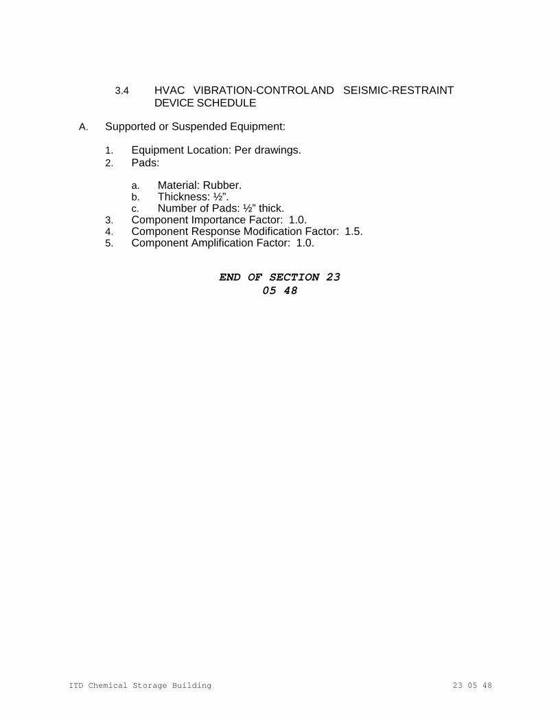
ITD Chemical Storage Building
23 05 48
3.4 HVAC VIBRATION-CONTROL AND SEISMIC-RESTRAINTDEVICE SCHEDULE
A. Supported or Suspended Equipment:
1. Equipment Location: Per drawings. 2. Pads:
a. Material: Rubber. b. Thickness: ½”. c. Number of Pads: ½” thick.
3. Component Importance Factor: 1.0. 4. Component Response Modification Factor: 1.5. 5. Component Amplification Factor: 1.0.
END OF SECTION 23 05 48
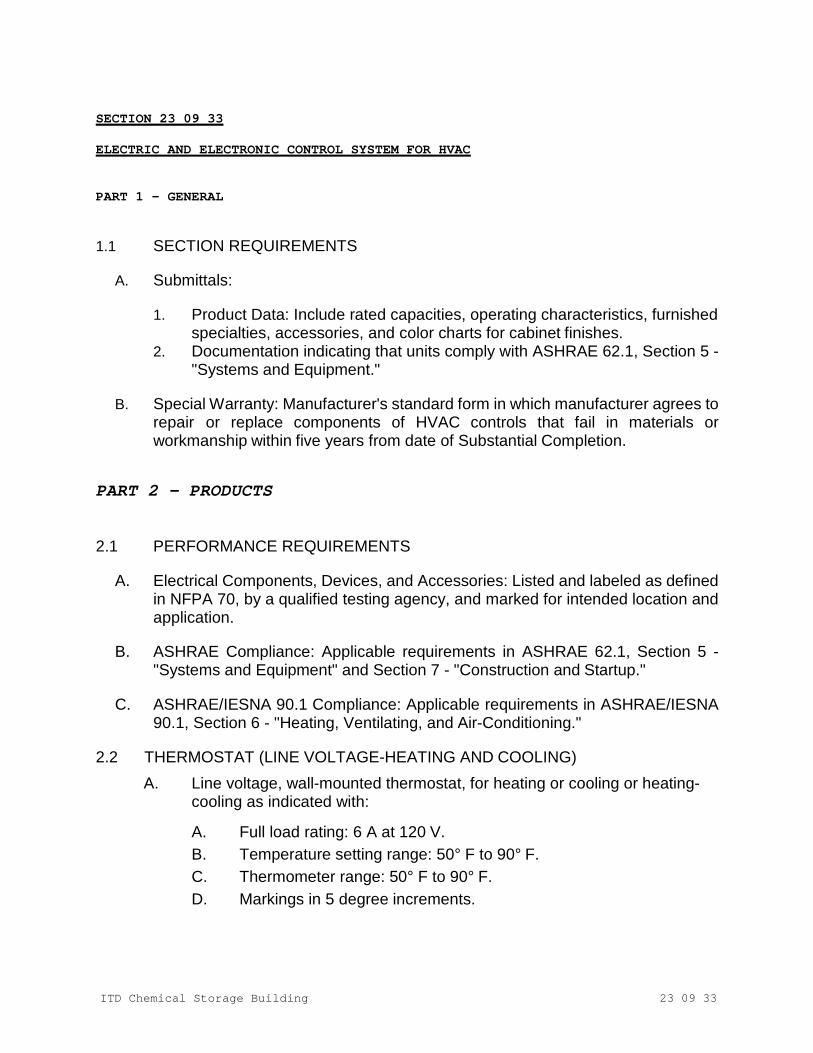
ITD Chemical Storage Building
23 09 33
SECTION 23 09 33 ELECTRIC AND ELECTRONIC CONTROL SYSTEM FOR HVAC
PART 1 - GENERAL
1.1 SECTION REQUIREMENTS
A. Submittals:
1. Product Data: Include rated capacities, operating characteristics, furnished specialties, accessories, and color charts for cabinet finishes.
2. Documentation indicating that units comply with ASHRAE 62.1, Section 5 - "Systems and Equipment."
B. Special Warranty: Manufacturer's standard form in which manufacturer agrees to
repair or replace components of HVAC controls that fail in materials or workmanship within five years from date of Substantial Completion.
PART 2 - PRODUCTS
2.1 PERFORMANCE REQUIREMENTS
A. Electrical Components, Devices, and Accessories: Listed and labeled as defined in NFPA 70, by a qualified testing agency, and marked for intended location and application.
B. ASHRAE Compliance: Applicable requirements in ASHRAE 62.1, Section 5 -
"Systems and Equipment" and Section 7 - "Construction and Startup."
C. ASHRAE/IESNA 90.1 Compliance: Applicable requirements in ASHRAE/IESNA 90.1, Section 6 - "Heating, Ventilating, and Air-Conditioning."
2.2 THERMOSTAT (LINE VOLTAGE-HEATING AND COOLING)
A. Line voltage, wall-mounted thermostat, for heating or cooling or heating-cooling as indicated with:
A. Full load rating: 6 A at 120 V. B. Temperature setting range: 50° F to 90° F. C. Thermometer range: 50° F to 90° F. D. Markings in 5 degree increments.
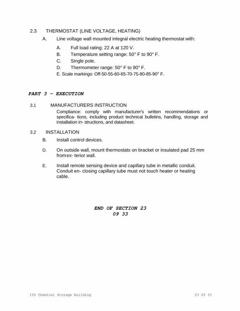
ITD Chemical Storage Building
23 09 33
2.3 THERMOSTAT (LINE VOLTAGE, HEATING) A. Line voltage wall mounted integral electric heating thermostat with:
A. Full load rating: 22 A at 120 V. B. Temperature setting range: 50° F to 90° F. C. Single pole. D. Thermometer range: 50° F to 90° F. E. Scale markings: Off-50-55-60-65-70-75-80-85-90° F.
PART 3 - EXECUTION
3.1 MANUFACTURERS INSTRUCTION Compliance: comply with manufacturer's written recommendations or specifica- tions, including product technical bulletins, handling, storage and installation in- structions, and datasheet.
3.2 INSTALLATION
B. Install control devices.
D. On outside wall, mount thermostats on bracket or insulated pad 25 mm from ex- terior wall.
E. Install remote sensing device and capillary tube in metallic conduit.
Conduit en- closing capillary tube must not touch heater or heating cable.
END OF SECTION 23 09 33
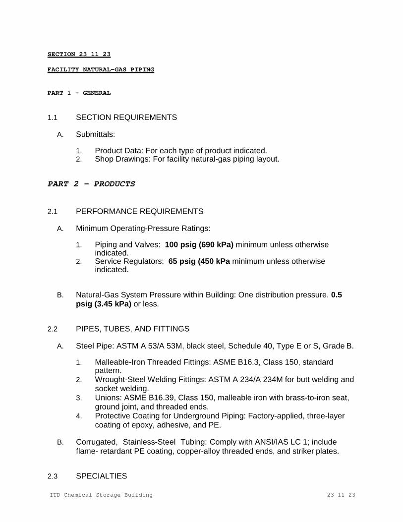
ITD Chemical Storage Building
23 11 23
SECTION 23 11 23 FACILITY NATURAL-GAS PIPING
PART 1 - GENERAL
1.1 SECTION REQUIREMENTS
A. Submittals:
1. Product Data: For each type of product indicated. 2. Shop Drawings: For facility natural-gas piping layout.
PART 2 - PRODUCTS
2.1 PERFORMANCE REQUIREMENTS
A. Minimum Operating-Pressure Ratings:
1. Piping and Valves: 100 psig (690 kPa) minimum unless otherwise indicated.
2. Service Regulators: 65 psig (450 kPa minimum unless otherwise indicated.
B. Natural-Gas System Pressure within Building: One distribution pressure. 0.5 psig (3.45 kPa) or less.
2.2 PIPES, TUBES, AND FITTINGS
A. Steel Pipe: ASTM A 53/A 53M, black steel, Schedule 40, Type E or S, Grade B.
1. Malleable-Iron Threaded Fittings: ASME B16.3, Class 150, standard pattern.
2. Wrought-Steel Welding Fittings: ASTM A 234/A 234M for butt welding and socket welding.
3. Unions: ASME B16.39, Class 150, malleable iron with brass-to-iron seat, ground joint, and threaded ends.
4. Protective Coating for Underground Piping: Factory-applied, three-layer coating of epoxy, adhesive, and PE.
B. Corrugated, Stainless-Steel Tubing: Comply with ANSI/IAS LC 1; include
flame- retardant PE coating, copper-alloy threaded ends, and striker plates.
2.3 SPECIALTIES
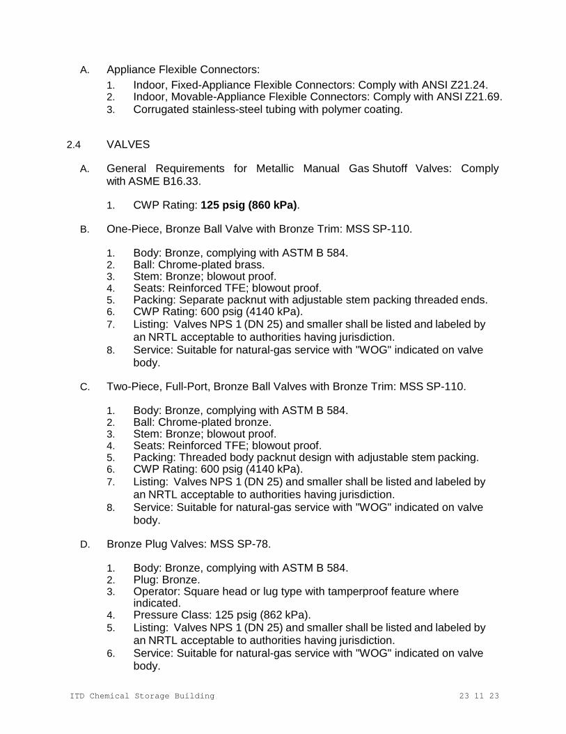
ITD Chemical Storage Building
23 11 23
A. Appliance Flexible Connectors: 1. Indoor, Fixed-Appliance Flexible Connectors: Comply with ANSI Z21.24. 2. Indoor, Movable-Appliance Flexible Connectors: Comply with ANSI Z21.69. 3. Corrugated stainless-steel tubing with polymer coating.
2.4 VALVES
A. General Requirements for Metallic Manual Gas Shutoff Valves: Comply with ASME B16.33.
1. CWP Rating: 125 psig (860 kPa).
B. One-Piece, Bronze Ball Valve with Bronze Trim: MSS SP-110.
1. Body: Bronze, complying with ASTM B 584. 2. Ball: Chrome-plated brass. 3. Stem: Bronze; blowout proof. 4. Seats: Reinforced TFE; blowout proof. 5. Packing: Separate packnut with adjustable stem packing threaded ends. 6. CWP Rating: 600 psig (4140 kPa). 7. Listing: Valves NPS 1 (DN 25) and smaller shall be listed and labeled by
an NRTL acceptable to authorities having jurisdiction. 8. Service: Suitable for natural-gas service with "WOG" indicated on valve
body.
C. Two-Piece, Full-Port, Bronze Ball Valves with Bronze Trim: MSS SP-110.
1. Body: Bronze, complying with ASTM B 584. 2. Ball: Chrome-plated bronze. 3. Stem: Bronze; blowout proof. 4. Seats: Reinforced TFE; blowout proof. 5. Packing: Threaded body packnut design with adjustable stem packing. 6. CWP Rating: 600 psig (4140 kPa). 7. Listing: Valves NPS 1 (DN 25) and smaller shall be listed and labeled by
an NRTL acceptable to authorities having jurisdiction. 8. Service: Suitable for natural-gas service with "WOG" indicated on valve
body.
D. Bronze Plug Valves: MSS SP-78.
1. Body: Bronze, complying with ASTM B 584. 2. Plug: Bronze. 3. Operator: Square head or lug type with tamperproof feature where
indicated. 4. Pressure Class: 125 psig (862 kPa). 5. Listing: Valves NPS 1 (DN 25) and smaller shall be listed and labeled by
an NRTL acceptable to authorities having jurisdiction. 6. Service: Suitable for natural-gas service with "WOG" indicated on valve
body.
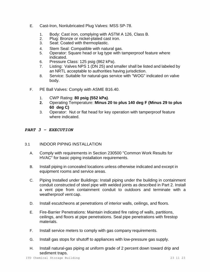
ITD Chemical Storage Building
23 11 23
E. Cast-Iron, Nonlubricated Plug Valves: MSS SP-78.
1. Body: Cast iron, complying with ASTM A 126, Class B. 2. Plug: Bronze or nickel-plated cast iron. 3. Seat: Coated with thermoplastic. 4. Stem Seal: Compatible with natural gas. 5. Operator: Square head or lug type with tamperproof feature where
indicated. 6. Pressure Class: 125 psig (862 kPa). 7. Listing: Valves NPS 1 (DN 25) and smaller shall be listed and labeled by
an NRTL acceptable to authorities having jurisdiction. 8. Service: Suitable for natural-gas service with "WOG" indicated on valve
body.
F. PE Ball Valves: Comply with ASME B16.40.
1. CWP Rating: 80 psig (552 kPa). 2. Operating Temperature: Minus 20 to plus 140 deg F (Minus 29 to plus
60 deg C) 3. Operator: Nut or flat head for key operation with tamperproof feature
where indicated.
PART 3 - EXECUTION
3.1 INDOOR PIPING INSTALLATION
A. Comply with requirements in Section 230500 "Common Work Results for HVAC" for basic piping installation requirements.
B. Install piping in concealed locations unless otherwise indicated and except in
equipment rooms and service areas.
C. Piping Installed under Buildings: Install piping under the building in containment conduit constructed of steel pipe with welded joints as described in Part 2. Install a vent pipe from containment conduit to outdoors and terminate with a weatherproof vent cap.
D. Install escutcheons at penetrations of interior walls, ceilings, and floors.
E. Fire-Barrier Penetrations: Maintain indicated fire rating of walls, partitions,
ceilings, and floors at pipe penetrations. Seal pipe penetrations with firestop materials.
F. Install service meters to comply with gas company requirements.
G. Install gas stops for shutoff to appliances with low-pressure gas supply.
H. Install natural-gas piping at uniform grade of 2 percent down toward drip and
sediment traps.

ITD Chemical Storage Building
23 11 23
I. Use eccentric reducer fittings to make reductions in pipe sizes. Install fittings
with level side down.
J. Connect branch piping from top or side of horizontal piping.
K. Install unions in pipes NPS 2 (DN 50) and smaller, adjacent to each valve, at final connection to each piece of equipment. Unions are not required at flanged connections.
3.2 PIPING JOINT CONSTRUCTION
A. Threaded Joints: Thread pipe with tapered pipe threads complying with ASME B1.20.1.
B. Welded Joints: Construct joints according to AWS D10.12M/D10.12, using
qualified processes and welding operators.
C. Joints in Steel Piping with Protective Coating: Apply joint cover kits to pipe after joining to cover, seal, and protect joints.
D. Brazed Joints: Construct joints according to AWS's "Brazing Handbook," "Pipe
and Tube" Chapter.
E. Flanged Joints: Install gasket material, size, type, and thickness appropriate for natural- gas service. Install gasket concentrically positioned.
F. Flared Joints: Cut tubing with roll cutting tool. Flare tube end with tool to result in
flare dimensions conforming to SAE J513. Tighten finger tight then using wrench. Do not overtighten.
G. PE Piping Heat-Fusion Joints: Clean and dry joining surfaces by wiping with
clean cloth or paper towels. Join according to ASTM D 2657.
1. Plain-End Pipe and Fittings: Use butt fusion. 2. Plain-End Pipe and Socket Fittings: Use socket fusion.
3.3 VALVE INSTALLATION
A. Install manual gas shutoff valve for each gas appliance ahead of corrugated stainless- steel tubing, aluminum, or copper connector.
3.4 INDOOR PIPING SCHEDULE FOR SYSTEM PRESSURES LESS THAN 0.5 PSIG (3.45 kPa)
A. Aboveground, branch piping NPS 1 (DN 25) and smaller shall be one of the
following:
1. Corrugated stainless-steel tubing with mechanical fittings having socket or
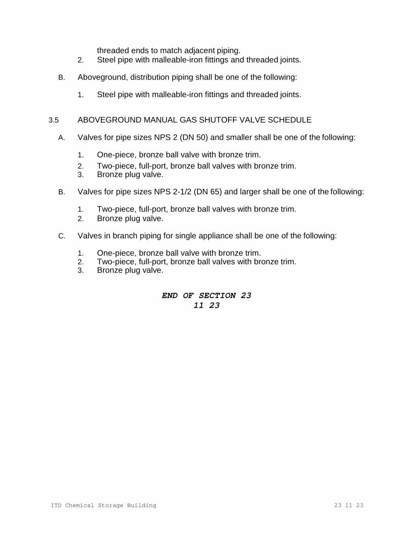
ITD Chemical Storage Building
23 11 23
threaded ends to match adjacent piping. 2. Steel pipe with malleable-iron fittings and threaded joints.
B. Aboveground, distribution piping shall be one of the following:
1. Steel pipe with malleable-iron fittings and threaded joints.
3.5 ABOVEGROUND MANUAL GAS SHUTOFF VALVE SCHEDULE
A. Valves for pipe sizes NPS 2 (DN 50) and smaller shall be one of the following:
1. One-piece, bronze ball valve with bronze trim. 2. Two-piece, full-port, bronze ball valves with bronze trim. 3. Bronze plug valve.
B. Valves for pipe sizes NPS 2-1/2 (DN 65) and larger shall be one of the following:
1. Two-piece, full-port, bronze ball valves with bronze trim. 2. Bronze plug valve.
C. Valves in branch piping for single appliance shall be one of the following:
1. One-piece, bronze ball valve with bronze trim. 2. Two-piece, full-port, bronze ball valves with bronze trim. 3. Bronze plug valve.
END OF SECTION 23 11 23
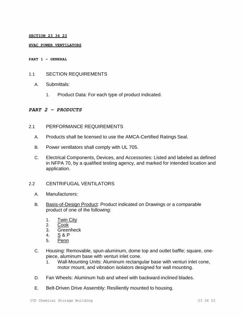
ITD Chemical Storage Building
23 34 23
SECTION 23 34 23 HVAC POWER VENTILATORS
PART 1 - GENERAL
1.1 SECTION REQUIREMENTS
A. Submittals:
1. Product Data: For each type of product indicated.
PART 2 - PRODUCTS
2.1 PERFORMANCE REQUIREMENTS
A. Products shall be licensed to use the AMCA-Certified Ratings Seal.
B. Power ventilators shall comply with UL 705.
C. Electrical Components, Devices, and Accessories: Listed and labeled as defined in NFPA 70, by a qualified testing agency, and marked for intended location and application.
2.2 CENTRIFUGAL VENTILATORS
A. Manufacturers:
B. Basis-of-Design Product: Product indicated on Drawings or a comparable product of one of the following:
1. Twin City 2. Cook 3. Greenheck 4. S & P 5. Penn
C. Housing: Removable, spun-aluminum, dome top and outlet baffle; square, one-
piece, aluminum base with venturi inlet cone. 1. Wall-Mounting Units: Aluminum rectangular base with venturi inlet cone,
motor mount, and vibration isolators designed for wall mounting.
D. Fan Wheels: Aluminum hub and wheel with backward-inclined blades.
E. Belt-Driven Drive Assembly: Resiliently mounted to housing.

ITD Chemical Storage Building
23 34 23
1. Fan Shaft: Turned, ground, and polished steel; keyed to wheel hub. 2. Shaft Bearings: Permanently lubricated, permanently sealed, self-aligning
ball bearings. 3. Pulleys: Cast-iron, adjustable-pitch motor pulley. 4. Fan and motor isolated from exhaust airstream.
F. Accessories:
1. Bird Screens: Removable, 1/2-inch (13-mm) mesh, aluminum or brass wire. 2. Dampers: Counterbalanced, parallel-blade, backdraft dampers mounted in
curb base; factory set to close when fan stops. 3. Motorized Dampers: Parallel-blade dampers mounted in curb base with
electric actuator; wired to close when fan stops.
PART 3 - EXECUTION
3.1 INSTALLATION
A. Install units with clearances for service and maintenance.
B. Wall-Mounted Units: Install in wall structure, according to ARI Guideline B. In-Line
C. Ground power ventilators.
END OF SECTION 23 34 23
ITD Chemical Storage Building
23 37 13
SECTION 23 37 13 DIFFUSERS, REGISTERS, AND GRILLES
PART 1 - GENERAL
1.1 SECTION REQUIREMENTS
A. Submittals:
1. Product Data: For each type of product indicated, including color charts for factory finishes.
PART 2 - PRODUCTS
2.1 OUTLETS
A. Diffusers:
1. Manufacturers: 2. Basis-of-Design Product: Product indicated on Drawings or a comparable
product of one of the following: a. Carnes. b. Price Industries. c. Titus. d. Tuttle & Bailey.
3. Material: Steel 4. Finish: Baked enamel, white 5. Mounting: Duct connection.
B. Wall Louver:
1. Manufacturers:
2. Basis-of-Design Product: Product indicated on Drawings or a comparable
product of one of the following:
3. a. Dayton b. Greenheck
4. Material: Aluminum. 5. Finish: Baked enamel, color selected by Architect.
ITD Chemical Storage Building
23 37 13
PART 3 - EXECUTION
3.1 INSTALLATION
A. Install diffusers, registers, and grilles level and plumb.
B. Ceiling-Mounted Outlets: Drawings indicate general arrangement of ducts, fittings, and accessories. Make final locations where indicated, as much as practical. For units installed in lay-in ceiling panels, locate units in the center of panel unless otherwise indicated. Where architectural features or other items conflict with installation, notify Architect for a determination of final location.
C. After installation, adjust diffusers, registers, and grilles to air patterns indicated,
or as directed, before starting air balancing.
END OF SECTION 23 37 13
ITD Chemical Storage Building
23 81 13
SECTION 23 81 13 PACKAGED TERMINAL AIR-CONDITIONERS
PART 1 - GENERAL
1.1 SECTION REQUIREMENTS
A. Submittals:
1. Product Data: For each type of product indicated.
a. Include color charts for cabinet finishes.
2. Shop Drawings: Including wall penetrations, seismic bracing, and attachments to other work.
PART 2 - PRODUCTS
2.1 PERFORMANCE REQUIREMENTS
A. Electrical Components, Devices, and Accessories: Listed and labeled as defined in NFPA 70, by a qualified testing agency, and marked for intended location and application.
B. ASHRAE Compliance: Applicable requirements in ASHRAE 62.1, Section 4 -
"Outdoor Air Quality," Section 5 - "Systems and Equipment," Section 6 - "Ventilation Rate Procedures," and Section 7 - "Construction and Startup."
C. ASHRAE/IESNA Compliance: Applicable requirements in ASHRAE/IESNA 90.1.
D. Warranties: Submit a written warranty signed by manufacturer agreeing to repair
or replace components that fail within five years after Substantial Completion.
2.2 PACKAGED UNITS
A. Manufacturers:
B. Basis-of-Design Product: Product indicated on Drawings or a comparable product of one of the following:
1. Carrier Corporation; a United Technologies company. 2. Friedrich Air Conditioning Co. 3. Amana. 4. Trane. 5. LG.
ITD Chemical Storage Building
23 81 13
C. Factory-assembled and -tested, self-contained, through-the-wall terminal units, with room cabinet, electric refrigeration system,heating, and temperature controls; fully charged with refrigerant and filled with oil; with cord-connected chassis.
D. Cabinet: Galvanized steel for wall with wall sleeve mounting; baked-enamel
finish in standard color.
1. Discharge Grille and Access Door: Punched-louver discharge grille allowing four- way, discharge-air pattern, with hinged door in top of cabinet for access to controls.
2. Louvers: Extruded aluminum with enamel finish. 3. Subbase: Enameled steel with adjustable leveling feet and adjustable end
plates. 4. Wall Sleeves: Galvanized steel with polyester finish.
E. Refrigeration System: Direct-expansion indoor coil with capillary restrictor,
hermetically sealed scroll compressor with vibration isolation and overload protection. Include the following:
1. Outdoor coil and fan. 2. Accumulator. 3. Constant-pressure expansion valve. 4. Reversing valve.
F. Indoor Fan: Forward curved, centrifugal, with positive-pressure ventilation
damper with operator.
G. Fan Motors: Permanent-split-capacitor motors.
H. Filters: Washable polyurethane in molded plastic frame.
I. Electric-Resistance Heating Coil: Nickel-chromium-wire, electric-resistance heating elements with contactor and high-temperature-limit switch.
J. Condensate Drain: Drain pan to direct condensate to outdoor coil for re-
evaporation.
K. Controls: Unit-mounted, adjustable thermostat with heat anticipator, off-heat-auto-cool switch, and high-low fan switch. Include the following features:
1. Low Ambient Lockout Control: Prevents cooling-cycle operation below 40
deg F (5 deg C) outdoor air temperature. 2. Heat-Pump Ambient Control: Field-adjustable switch changes to heat-pump
heating operation above 40 deg F (5 deg C) and to supplemental heating below plus 25 deg F (minus 4 deg C).
3. Reverse-Cycle Defrost: Solid-state sensor monitors frost buildup on indoor coil and reverses unit to melt frost.
ITD Chemical Storage Building
23 81 13
2.3 SOURCE QUALITY CONTROL
A. Sound-Power Level Ratings: Factory test to comply with ARI 300, "Sound Rating and Sound Transmission Loss of Packaged Terminal Equipment."
B. Unit Performance Ratings: Factory test to comply with ARI 310/380/CSA C744, "Packaged Terminal Air-Conditioners and Heat Pumps."
PART 3 - EXECUTION
3.1 INSTALLATION
A. Set wall sleeve level and plumb in exterior wall. Coordinate installation with exterior wall construction.
B. Install units level and plumb, and anchor.
C. Connect units to wiring systems and to ground.
END OF SECTION 23 81 13

ITD Chemical Storage Building
23 82 39
SECTION 23 82 39 HIGH INTENSITY SPACE HEATERS
PART 1 - GENERAL
1.1 SECTION REQUIREMENTS
A. Submittals:
1. Product Data: Include rated capacities, operating characteristics, furnished specialties, accessories, and color charts for cabinet finishes.
2. Documentation indicating that units comply with ASHRAE 62.1, Section 5 - "Systems and Equipment."
B. Special Warranty: Manufacturer's standard form in which manufacturer agrees to
repair or replace components of unit heaters that fail in materials or workmanship within five years from date of Substantial Completion.
PART 2 - PRODUCTS
2.1 PERFORMANCE REQUIREMENTS
A. Electrical Components, Devices, and Accessories: Listed and labeled as defined in NFPA 70, by a qualified testing agency, and marked for intended location and application.
B. ASHRAE Compliance: Applicable requirements in ASHRAE 62.1, Section 5 -
"Systems and Equipment" and Section 7 - "Construction and Startup."
C. ASHRAE/IESNA 90.1 Compliance: Applicable requirements in ASHRAE/IESNA 90.1, Section 6 - "Heating, Ventilating, and Air-Conditioning."
2.2 HI SPACE HEATERS
A. Manufacturers:
B. Basis-of-Design Product: Product indicated on Drawings or a comparable product of one of the following:
1. Reznor. 2. Modine. 3. Sterling.
C. Factory-assembled and -tested units complying with Designed Certified by CSA.
ITD Chemical Storage Building
23 82 39
1. Airstream Surfaces: Surfaces in contact with the airstream shall comply with requirements in ASHRAE 62.1.
D. Cabinet:
1. Surface, ceiling mounting.
PART 3 - EXECUTION
3.1 INSTALLATION
A. Install space heaters to comply with NFPA 90A and manufacturer mounting heights.
B. Install units level and plumb and firmly anchored.
C. Connect units to wiring systems and to ground.
END OF SECTION 23 82 39
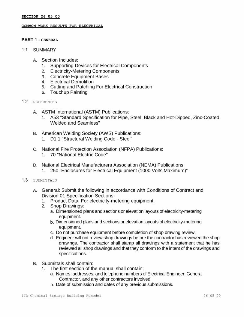
ITD Chemical Storage Building Remodel,
26 05 00
SECTION 26 05 00
COMMON WORK RESULTS FOR ELECTRICAL
GENERAL
SUMMARY
A. Section Includes: 1. Supporting Devices for Electrical Components 2. Electricity-Metering Components 3. Concrete Equipment Bases 4. Electrical Demolition 5. Cutting and Patching For Electrical Construction 6. Touchup Painting
REFERENCES
A. ASTM International (ASTM) Publications: 1. A53 "Standard Specification for Pipe, Steel, Black and Hot-Dipped, Zinc-Coated,
Welded and Seamless"
B. American Welding Society (AWS) Publications: 1. D1.1 "Structural Welding Code - Steel"
C. National Fire Protection Association (NFPA) Publications:
1. 70 "National Electric Code"
D. National Electrical Manufacturers Association (NEMA) Publications: 1. 250 “Enclosures for Electrical Equipment (1000 Volts Maximum)”
SUBMITTALS
A. General: Submit the following in accordance with Conditions of Contract and Division 01 Specification Sections: 1. Product Data: For electricity-metering equipment. 2. Shop Drawings:
Dimensioned plans and sections or elevation layouts of electricity-metering equipment.
Dimensioned plans and sections or elevation layouts of electricity-metering equipment.
Do not purchase equipment before completion of shop drawing review. Engineer will not review shop drawings before the contractor has reviewed the shop
drawings. The contractor shall stamp all drawings with a statement that he has reviewed all shop drawings and that they conform to the intent of the drawings and specifications.
B. Submittals shall contain:
1. The first section of the manual shall contain: Names, addresses, and telephone numbers of Electrical Engineer, General
Contractor, and any other contractors involved. Date of submission and dates of any previous submissions.
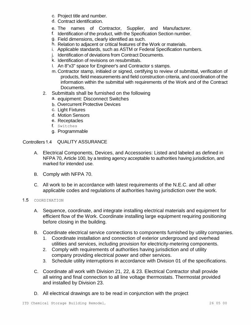
ITD Chemical Storage Building Remodel,
26 05 00
Project title and number. Contract identification. The names of Contractor, Supplier, and Manufacturer. Identification of the product, with the Specification Section number. Field dimensions, clearly identified as such. Relation to adjacent or critical features of the Work or materials.
Applicable standards, such as ASTM or Federal Specification numbers. Identification of deviations from Contract Documents. Identification of revisions on resubmittals. An 8"x3" space for Engineer's and Contractor s stamps. Contractor stamp, initialed or signed, certifying to review of submittal, verification of
products, field measurements and field construction criteria, and coordination of the information within the submittal with requirements of the Work and of the Contract Documents.
2. Submittals shall be furnished on the following equipment: Disconnect Switches
Overcurrent Protective Devices Light Fixtures Motion Sensors Receptacles
Switches Programmable
Controllers QUALITY ASSURANCE
A. Electrical Components, Devices, and Accessories: Listed and labeled as defined in NFPA 70, Article 100, by a testing agency acceptable to authorities having jurisdiction, and marked for intended use.
B. Comply with NFPA 70.
C. All work to be in accordance with latest requirements of the N.E.C. and all other
applicable codes and regulations of authorities having jurisdiction over the work.
COORDINATION
A. Sequence, coordinate, and integrate installing electrical materials and equipment for efficient flow of the Work. Coordinate installing large equipment requiring positioning before closing in the building.
B. Coordinate electrical service connections to components furnished by utility companies.
1. Coordinate installation and connection of exterior underground and overhead utilities and services, including provision for electricity-metering components.
2. Comply with requirements of authorities having jurisdiction and of utility company providing electrical power and other services.
3. Schedule utility interruptions in accordance with Division 01 of the specifications.
C. Coordinate all work with Division 21, 22, & 23. Electrical Contractor shall provide all wiring and final connection to all line voltage thermostats. Thermostat provided and installed by Division 23.
D. All electrical drawings are to be read in conjunction with the project
ITD Chemical Storage Building Remodel,
26 05 00
specifications and all other related contract drawings.
E. The contractor shall examine the site and observe the conditions under which the work will be done or other circumstances which will affect the contemplated work. No allowance will be made subsequently in the connection for any error or negligence on the contractor’s part.
F. The contractor shall verify exact location, size and extent of all existing utilities, obstructions and/or other conditions which may affect the proposed work under the project. The contractor shall take every precaution to prevent damage to existing work and shall repair any damage as a result of this work.
G. The contractor shall verify all door swings in the field and mount switches on
knob side of doors or as approved by the engineer.
H. The contractor shall carefully examine all contract drawings/specifications and be responsible for the proper fittings of materials and equipment at each location as indicated without substantial alteration. The drawings are generally diagrammatic and because of the small scale of the drawings, it is not possible to indicate all offsets, fittings and accessories which may be required. Furnishing such fittings that are required to meet such conditions shall be furnished and installed at no cost.
PRODUCTS
SUPPORTING DEVICES
A. Material: Cold-formed steel, with corrosion-resistant coating acceptable to authorities having jurisdiction.
B. Metal Items for Use Outdoors or in Damp Locations: Hot-dip galvanized steel.
C. Slotted-Steel Channel Supports: Flange edges turned toward web, and 9/16-inch
diameter slotted holes at a maximum of 2 inches o.c., in webs. 1. Channel Thickness: Selected to suit structural loading. 2. Fittings and Accessories: Products of the same manufacturer as channel supports.
D. Raceway and Cable Supports: Manufactured clevis hangers, riser clamps, straps,
threaded C-clamps with retainers, ceiling trapeze hangers, wall brackets, and spring-steel clamps or click-type hangers.
E. Pipe Sleeves: ASTM A53, Type E, Grade A, Schedule 40, galvanized steel, plain ends.
F. Cable Supports for Vertical Conduit: Factory-fabricated assembly consisting of
threaded body and insulating wedging plug for nonarmored electrical cables in riser conduits. Plugs have number and size of conductor gripping holes as required to suit individual risers. Body constructed of malleable-iron casting with hot-dip galvanized finish.
G. Expansion Anchors: Carbon-steel wedge or sleeve type.
H. Toggle Bolts: All-steel springhead type.
ITD Chemical Storage Building Remodel,
26 05 00
TOUCHUP PAINT
A. For Equipment: Equipment manufacturer's paint selected to match installed equipment finish.
B. Galvanized Surfaces: Zinc-rich paint recommended by item manufacturer.
EXECUTION
ELECTRICAL EQUIPMENT INSTALLATION
A. Headroom Maintenance: If mounting heights or other location criteria are not indicated, arrange and install components and equipment to provide the maximum possible headroom.
B. Materials and Components: Install level, plumb, and parallel and perpendicular
to other building systems and components, unless otherwise indicated.
C. Equipment: Install to facilitate service, maintenance, and repair or replacement of components. Connect for ease of disconnecting, with minimum interference with other installations.
D. Right of Way: Give to raceways and piping systems installed at a required slope.
E. Coordinate work with other trades and install conduit and boxes to clear
embedded ducts, openings, etc. and all structural features.
F. Unless otherwise noted, mounting heights, as shown, are from finished floor to top of panelboard and to centerline of other equipment. Coordinate all mounting heights with contract drawings, local code requirements, and all A.D.A. requirements. 1. Toggle (snap) switch: 4’-0”. 2. Enclosed circuit breaker: 5’-0” 3. Disconnect (safety) switch: 5’-0”. 4. Motor starter: 5’-0”. 5. Panelboard: 6’-6”.
ELECTRICAL SUPPORTING DEVICE APPLICATION
A. Damp Locations, Pool Equipment Rooms, Storage Rooms and Outdoors: Hot-dip galvanized materials or nonmetallic, U-channel system components.
B. Dry Locations: Steel materials.
C. Support Clamps for PVC Raceways: Click-type clamp system.
D. Selection of Supports: Comply with manufacturer's written instructions.
E. Strength of Supports: Adequate to carry present and future loads, times a safety
factor of at least four; minimum of 200-lb design load.
ITD Chemical Storage Building Remodel,
26 05 00
SUPPORT INSTALLATION
A. Install support devices to securely and permanently fasten and support electrical components.
B. Install individual and multiple raceway hangers and riser clamps to support
raceways. Provide U-bolts, clamps, attachments, and other hardware necessary for hanger assemblies and for securing hanger rods and conduits.
C. Support parallel runs of horizontal raceways together on trapeze- or bracket-type
hangers.
D. Size supports for multiple raceway installations so capacity can be increased by a 25 percent minimum in the future.
E. Support individual horizontal raceways with separate, malleable-iron pipe hangers or clamps.
F. Install 1/4-inch- diameter or larger threaded steel hanger rods, unless otherwise
indicated.
G. Spring-steel fasteners specifically designed for supporting single conduits or tubing may be used instead of malleable-iron hangers for 1-1/2-inch and smaller raceways serving lighting and receptacle branch circuits above suspended ceilings and for fastening raceways to slotted channel and angle supports.
H. Arrange supports in vertical runs so the weight of raceways and enclosed
conductors is carried entirely by raceway supports, with no weight load on raceway terminals.
I. Simultaneously install vertical conductor supports with conductors.
J. Separately support cast boxes that are threaded to raceways and used for fixture
support. Support sheet-metal boxes directly from the building structure or by bar hangers. If bar hangers are used, attach bar to raceways on opposite sides of the box and support the raceway with an approved fastener not more than 24 inches from the box.
K. Install metal channel racks for mounting cabinets, panelboards, disconnect switches,
control enclosures, pull and junction boxes, transformers, and other devices unless components are mounted directly to structural elements of adequate strength.
L. Install sleeves for cable and raceway penetrations of concrete slabs and walls
unless core- drilled holes are used. Install sleeves for cable and raceway penetrations of masonry and fire-rated gypsum walls and of all other fire-rated floor and wall assemblies. Install sleeves during erection of concrete and masonry walls.
M. Securely fasten electrical items and their supports to the building structure, unless
otherwise indicated. Perform fastening according to the following unless other fastening methods are indicated: 1. Wood: Fasten with wood screws or screw-type nails. 2. Masonry: Toggle bolts on hollow masonry units and expansion bolts on solid
ITD Chemical Storage Building Remodel,
26 05 00
masonry units. 3. New Concrete: Concrete inserts with machine screws and bolts. 4. Existing Concrete: Expansion bolts. 5. Steel: Welded threaded studs or spring-tension clamps on
steel. Field Welding: Comply with AWS D1.1. 6. Welding to steel structure may be used only for threaded studs, not for
conduits, pipe straps, or other items. 7. Light Steel: Sheet-metal screws. 8. Fasteners: Select so the load applied to each fastener does not exceed 25
percent of its proof-test load.
FIRESTOPPING
A. Apply firestopping to cable and raceway penetrations of fire-rated floor and wall assemblies to achieve fire-resistance rating of the assembly.
CUTTING AND PATCHING
A. Cut, channel, chase, and drill floors, walls, partitions, ceilings, and other surfaces required to permit electrical installations. Perform cutting by skilled mechanics of trades involved.
B. Repair and refinish disturbed finish materials and other surfaces to match adjacent
undisturbed surfaces. Install new fireproofing where existing firestopping has been disturbed. Repair and refinish materials and other surfaces by skilled mechanics of trades involved.
FIELD QUALITY CONTROL
A. Inspect installed components for damage and faulty work, including the following: 1. Supporting devices for electrical components. 2. Electrical demolition. 3. Cutting and patching for electrical construction. 4. Touchup painting.
REFINISHING AND TOUCHUP PAINTING
A. Refinish and touch up paint. Paint materials and application requirements are specified in Section 09 90 00 - "Painting."
CLEANING AND PROTECTION
A. On completion of installation, including outlets, fittings, and devices, inspect exposed finish. Remove burrs, dirt, paint spots, and construction debris.
B. Protect equipment and installations and maintain conditions to ensure that coatings,
finishes, and cabinets are without damage or deterioration at time of Substantial Completion.
END OF SECTION

ITD Chemical Storage Building Remodel,
26 05 19
SECTION 26 05 19
LOW-VOLTAGE ELECTRICAL POWER CONDUCTORS AND CABLES
GENERAL
SUMMARY
A. Section Includes: 1. Building wires and cables and associated connectors, splices, and
terminations for wiring systems rated 600 V and less.
REFERENCES
A. National Electrical Manufacturer’s Association (NEMA) Publications: 1. WC 26 “Binational Wire and Cable Packaging Standard” 2. WC 70 “Nonshielded Power Cables Rated 2000 Volts or less for the
Distribution of Electrical Energy”
B. National Fire Protection Association (NFPA) Publications: 1. 70 "National Electric Code"
C. Underwriter's Laboratories, Inc. (UL) Publications:
1. 486A “Standard For Wire Connectors and Soldering Lugs for Use with Copper Conductors”
2. 486B “Standard for Wire Connectors for Use With Aluminum Conductors”
SUBMITTALS
A. General: Submit the following in accordance with Conditions of Contract and Division 01 Specification Sections: 1. Field Test Reports: Indicate and interpret test results for compliance with
performance requirements.
QUALITY ASSURANCE
A. Listing and Labeling: Provide wires and cables specified in this Section that are listed and labeled. 1. The Terms "Listed" and "Labeled": As defined in NFPA 70, Article 100. 2. Listing and Labeling Agency Qualifications: A "Nationally Recognized
Testing Laboratory" as defined in OSHA Regulation 1910.7.
B. Comply with NFPA 70.
DELIVERY, STORAGE, AND HANDLING
A. Deliver wires and cables according to NEMA WC 26.
COORDINATION
A. Coordinate layout and installation of cables with other installations.
B. Revise locations and elevations from those indicated, as required to suit field
ITD Chemical Storage Building Remodel,
26 05 19
conditions and as approved by Owner's Representative.
PRODUCTS
BUILDING WIRES AND CABLES
A. Approved Manufacturers: 1. American Insulated Wire Corp.; Leviton Manufacturing Co. (800-366-2492) 2. Carol Cable Co., Inc. (401-728-7000) 3. Southwire Company (800-444-1700) 4. Alcan Cable Division of Alcan Aluminum Corporation (770-392-2368)
B. UL-listed building wires and cables with conductor material, insulation type,
cable construction, and rating as specified in Part 3 "Wire and Insulation Applications" Article.
C. Rubber Insulation Material: Comply with NEMA WC 70.
D. Thermoplastic Insulation Material: Comply with NEMA WC 70.
E. Cross-Linked Polyethylene Insulation Material: Comply with NEMA WC 70.
F. Ethylene Propylene Rubber Insulation Material: Comply with NEMA WC 70.
G. Conductor Material: Copper
1. Feeders 100 ampere or greater may be aluminum "Alcan Stabiloy #8000", or approved substitution by listed manufacturers. Upsize conduit and wire as required.
2. All aluminum conductors shall include Burndy Hyplug connectors at each end of cable.
H. Stranding: Solid conductor for No. 10 AWG and smaller; stranded conductor for
larger than No. 10 AWG.
CONNECTORS AND SPLICES
A. Approved Manufacturers: 1. AMP Incorporated (800-522-6752) 2. General Signal; O-Z/Gedney Unit (203-584-0571) 3. Square D Co.; a Division of Groupe Schneider (888-778-2733) 4. Alcan Cable Division of Alcan Aluminum Corporation (770-392-2368)
B. UL-listed, factory-fabricated wiring connectors of size, ampacity rating, material,
type, and class for application and service indicated. Comply with Project's installation requirements and as specified in Part 3 "Wire and Insulation Applications" Article.
EXECUTION
EXAMINATION
ITD Chemical Storage Building Remodel,
26 05 19
A. Examine raceways and building finishes to receive wires and cables for compliance with requirements for installation tolerances and other conditions affecting performance of wires and cables. Do not proceed with installation until unsatisfactory conditions have been corrected.
WIRE AND INSULATION APPLICATIONS
A. Service Entrance: Type RHW or THWN, in raceway
B. Horizontal Feeders: Type THHN/THWN, in raceway
C. Vertical Feeders: Type THHN/THWW in raceway
D. Horizontal Branch Circuits: Type THHN/THWN, in raceway
E. Vertical Branch Circuits: Type THNN/THWW in raceway
INSTALLATION
A. Install wires and cables as indicated, according to manufacturer's written instructions and NECA's "Standard of Installation."
B. Pull Conductors: Use manufacturer-approved pulling compound or lubricant
where necessary; compound used must not deteriorate conductor or insulation. Do not exceed manufacturer's recommended maximum pulling tensions and sidewall pressure values.
C. Use pulling means, including fish tape, cable, rope, and basket-weave wire/cable
grips, that will not damage cables or raceway.
D. Install exposed cables, parallel and perpendicular to surfaces of exposed structural members, and follow surface contours where possible.
E. Support cables according to Section 26 05 00 - "Common Work Results for Electrical."
F. Identify wires and cables according to Section 26 05 53 "Identification for Electrical
Systems."
CONNECTIONS
A. Conductor Splices: Keep to minimum.
B. Install splices and tapes that possess equivalent or better mechanical strength and insulation ratings than conductors being spliced.
C. Use splice and tap connectors compatible with conductor material.
D. Use oxide inhibitor in each splice and tap connector for aluminum conductors.
E. Wiring at Outlets: Install conductor at each outlet, with at least 12 inches of slack.
F. Connect outlets and components to wiring and to ground as indicated and
instructed by manufacturer.
ITD Chemical Storage Building Remodel,
26 05 19
G. Tighten electrical connectors and terminals according to manufacturer's published torque- tightening values. If manufacturer's torque values are not indicated, use those specified in UL 486A and UL 486B.
FIELD QUALITY CONTROL
A. Testing: On installation of wires and cables and before electrical circuitry has been energized, demonstrate product capability and compliance with requirements. 1. Perform meggar and continuity tests on all conductors.
B. Correct malfunctioning conductors and cables at Project site, where possible, and
retest to demonstrate compliance; otherwise, remove and replace with new units and retest.
END OF SECTION
ITD Chemical Storage Building Remodel,
26 05 26
SECTION 26 05 26
GROUNDING AND BONDING FOR ELECTRICAL SYSTEMS
GENERAL
SUMMARY
Section Includes: 1. Grounding of Electrical Systems and Equipment.
Grounding requirements specified in this Section may be supplemented by special requirements of systems described in other Sections.
REFERENCES
ASTM International (ASTM) Publications: 1. B3 “Standard Specification for Soft or Annealed Copper Wire” 2. B8 “Standard Specification for Concentric-Lay-Stranded Copper
Conductors, Hard, Medium-Hard, or Soft” 3. B33 “Standard Specification for Tinned Soft or Annealed Copper Wire for
Electrical Purposes”
Institute of Electrical and Electronics Engineers, Inc. (IEEE) Publications: 1. C2 “ASC C2 Eighth Interim Collection of the National Electrical Safety Code ®” 2. 81 “Instrumentation and Measurement” 3. 837 “Substations”
National Fire Protection Association (NFPA) Publications: 1. 70 "National Electric Code" 2. 780 “Standard for the Installation of Lightning Protection Systems”
Underwriter's Laboratories, Inc. (UL) Publications: 1. 96 “Standard for Safety for Lightning Protection Components” 2. 467 “Grounding and Bonding Equipment” 3. 486A “Standard For Wire Connectors and Soldering Lugs for Use with
Copper Conductors”
QUALITY ASSURANCE
Electrical Components, Devices, and Accessories: Listed and labeled as defined in NFPA 70, Article 100, by a testing agency acceptable to authorities having jurisdiction, and marked for intended use. 1. Comply with UL 467.
Comply with NFPA 70; for overhead-line construction and medium-voltage underground construction, comply with IEEE C2.
Comply with NFPA 780 and UL 96 when interconnecting with lightning protection system.
PRODUCTS
ITD Chemical Storage Building Remodel,
26 05 26
MANUFACTURERS
Approved Manufacturers: 1. Grounding Conductors, Cables, Connectors, and
Rods: Chance/Hubbell (573-682-5521) Copperweld Corp. (931-433-7177) Thomas & Betts, Electrical (800-816-7809)
GROUNDING CONDUCTORS
For insulated conductors, comply with Section 26 05 19 - "Low-Voltage Electrical Power Conductors and Cables."
Material: Copper.
Equipment Grounding Conductors: Insulated with green-colored insulation.
Bare Copper Conductors: Comply with the following: 1. Solid Conductors: ASTM B3. 2. Assembly of Stranded Conductors: ASTM B8. 3. Tinned Conductors: ASTM B33.
Copper Bonding Conductors: As follows: 1. Bonding Cable: 28 kcmil, 14 strands of No. 17 AWG copper conductor, 1/4
inch in diameter. 2. Bonding Conductor: No. 4 or No. 6 AWG, stranded copper conductor. 3. Bonding Jumper: Bare copper tape, braided bare copper conductors,
terminated with copper ferrules; 1-5/8 inches wide and 1/16 inch thick. 4. Tinned Bonding Jumper: Tinned-copper tape, braided copper conductors,
terminated with copper ferrules; 1-5/8 inches wide and 1/16 inch thick.
Grounding Bus: Bare, annealed copper bars of rectangular cross section, with insulators.
Equipment Ground Conductor (Green) shall be included with all circuit conductors where shown. In addition, provide a neutral conductor where applicable.
CONNECTOR PRODUCTS
Comply with IEEE 837 and UL 467; listed for use for specific types, sizes, and combinations of conductors and connected items.
Bolted Connectors: Bolted-pressure-type connectors, or compression type.
Welded Connectors: Exothermic-welded type, in kit form, and selected per manufacturer's written instructions.
EXECUTION
APPLICATION
Use only copper conductors for both insulated and bare grounding conductors in direct contact with earth, concrete, masonry, crushed stone, and similar materials.
ITD Chemical Storage Building Remodel,
26 05 26
In raceways, use insulated equipment grounding conductors.
Exothermic-Welded Connections: Use for connections to structural steel and for underground connections, except those at test wells.
Equipment Grounding Conductor Terminations: Use bolted pressure clamps.
Grounding Bus: Install in electrical and telephone equipment rooms, in rooms housing service equipment, and elsewhere as indicated. 1. Use insulated spacer; space 1 inch from wall and support from wall 6
inches above finished floor, unless otherwise indicated. 2. At doors, route the bus up to the top of the door frame, across the top of the
doorway, and down to the specified height above the floor.
EQUIPMENT GROUNDING CONDUCTORS
Comply with NFPA 70, Article 250, for types, sizes, and quantities of equipment grounding conductors, unless specific types, larger sizes, or more conductors than required by NFPA 70 are indicated.
Install equipment grounding conductors in all feeders and circuits.
Signal and Communication Systems: For telephone, alarm, voice and data, and other communication systems, provide No. 4 AWG minimum insulated grounding conductor in raceway from grounding electrode system to each service location, terminal cabinet, wiring closet, and central equipment location. 1. Service and Central Equipment Locations and Wiring Closets: Terminate
grounding conductor on a 1/4-by-2-by-12-inch grounding bus. 2. Terminal Cabinets: Terminate grounding conductor on cabinet grounding terminal.
INSTALLATION
Grounding Conductors: Route along shortest and straightest paths possible, unless otherwise indicated. Avoid obstructing access or placing conductors where they may be subjected to strain, impact, or damage.
Bonding Straps and Jumpers: Install so vibration by equipment mounted on vibration isolation hangers and supports is not transmitted to rigidly mounted equipment. Use exothermic-welded connectors for outdoor locations, unless a disconnect-type connection is required; then, use a bolted clamp. Bond straps directly to the basic structure taking care not to penetrate any adjacent parts. Install straps only in locations accessible for maintenance.
CONNECTIONS
General: Make connections so galvanic action or electrolysis possibility is minimized. Select connectors, connection hardware, conductors, and connection methods so metals in direct contact will be galvanically compatible. 1. Use electroplated or hot-tin-coated materials to ensure high conductivity and
to make contact points closer to order of galvanic series. 2. Make connections with clean, bare metal at points of contact. 3. Coat and seal connections having dissimilar metals with inert material to
prevent future penetration of moisture to contact surfaces.
ITD Chemical Storage Building Remodel,
26 05 26
Exothermic-Welded Connections: Comply with manufacturer's written instructions. Welds that are puffed up or that show convex surfaces indicating improper cleaning are not acceptable.
Equipment Grounding Conductor Terminations: For No. 8 AWG and larger, use pressure- type grounding lugs. No. 10 AWG and smaller grounding conductors may be terminated with winged pressure-type connectors.
Tighten screws and bolts for grounding and bonding connectors and terminals according to manufacturer's published torque-tightening values. If manufacturer's torque values are not indicated, use those specified in UL 486A .
Compression-Type Connections: Use hydraulic compression tools to provide correct circumferential pressure for compression connectors. Use tools and dies recommended by connector manufacturer. Provide embossing die code or other standard method to make a visible indication that a connector has been adequately compressed on grounding conductor.
END OF SECTION
ITD Chemical Storage Building Remodel,
26 05 33
SECTION 26 05 33
RACEWAYS AND BOXES FOR ELECTRICAL SYSTEMS
GENERAL
SUMMARY
A. Section Includes: 1. Raceways include the
following: RMC PVC, schedule 40 or 80 EMT
FMC LFMC LFNC RNC Wireways
Surface raceways 2. Boxes, enclosures, and cabinets include the
following: Device boxes Outlet boxes Pull and junction boxes
Cabinets and hinged-cover enclosures
REFERENCES
A. National Electrical Contractors Association (NECA) Publications: 1. 111 “Standard for Installing Nonmetallic Raceways (RNC, ENT, LFNC) (ANSI)”
B. National Electrical Manufacturer’s Association (NEMA) Publications:
1. 250 “Enclosures for Electrical Equipment (1000 Volts Maximum)” 2. ANSI/NEMA FB 1 “Fittings, Cast Metal Boxes, and Conduit Bodies for Conduit,
Electrical Metallic Tubing, and Cable” 3. ANSI/NEMA OS 1 “Sheet-Steel Outlet Boxes, Device Boxes, Covers,
and Box Supports” 4. RN 1 “Polyvinyl Chloride (PVC) Externally Coated Galvanized Rigid Steel
Conduit and Intermediate Metal Conduit” 5. TC 2 “Electrical Polyvinyl Chloride (PVC) Tubing and Conduit” 6. TC 3 “Polyvinyl Chloride (PVC) Fittings for Use with Rigid PVC Conduit and Tubing”
C. National Fire Protection Association (NFPA) Publications:
1. 70 "National Electric Code"
D. Underwriter's Laboratories, Inc. (UL) Publications: 1. 1660 “Liquid-Tight Flexible Nonmetallic Conduit”
DEFINITIONS
A. EMT: Electrical metallic tubing.
B. FMC: Flexible metal conduit.
ITD Chemical Storage Building Remodel,
26 05 33
C. IMC: Intermediate metal conduit. D. LFMC: Liquidtight flexible metal conduit.
E. LFNC: Liquidtight flexible nonmetallic conduit.
F. RMC: Rigid metal conduit.
G. RNC: Rigid nonmetallic conduit.
SUBMITTALS
A. General: Submit the following in accordance with Conditions of Contract and Division 01 Specification Sections: 1. Product Data: For surface raceways, wireways and fittings, floor boxes,
hinged-cover enclosures, and cabinets.
PRIOR APPROVAL
A. General: 1. Catalog and manufacturer's numbers are for the purpose of establishing
standards of quality and types of materials to be used. Products of other manufacturers may be used if equal in quality and design in the opinion of the Engineer and are specifically approved by the Engineer, in writing, 10 days prior to close of bidding.
2. Any conflict arising from the use of substituted equipment shall be the responsibility of the supplier of that equipment. The contractor and his supplier shall bear all costs required to make equipment comply with the intent of the plans and specifications.
QUALITY ASSURANCE
A. Listing and Labeling: Provide raceways and boxes specified in this Section that are listed and labeled. 1. The Terms "Listed" and "Labeled": As defined in NFPA 70, Article 100. 2. Listing and Labeling Agency Qualifications: A "Nationally Recognized
Testing Laboratory" as defined in OSHA Regulation 1910.7.
B. Comply with NECA's "Standard for Installing Nonmetallic Raceways (RNC, ENT, LFNC) (ANSI).”
C. Comply with NFPA 70.
COORDINATION
A. Coordinate layout and installation of raceways and boxes with other construction elements to ensure adequate headroom, working clearance, and access.
PRODUCTS
MANUFACTURERS
ITD Chemical Storage Building Remodel,
26 05 33
A. Approved Manufacturers:
1. Metal Conduit and Tubing: Anixter Brothers, Inc. (800-323-
8166) Carol Cable Co., Inc. (401-728-7000) Wheatland Tube Co. (800-
257-8128) 2. Flexible Conduit:
Carol Cable Co., Inc. (401-728-7000)
Electri-Flex Co. (800-323-6174) 3. Nonmetallic Conduit and Tubing:
Hubbell, Inc.; Raco, Inc. (800-722-6437) Lamson & Sessions; Carlon Electrical Products (800-322-7566) Thomas & Betts Corp. (800-816-7809)
4. Conduit Bodies and Fittings: Emerson Electric Co.; Appleton Electric Co. (800-727-5102) Hubbell, Inc.; Killark Electric Manufacturing Co. (314-531-0460) Lamson & Sessions; Carlon Electrical Products (800-322-7566)
METAL CONDUIT AND TUBING
A. Rigid Steel Conduit: ANSI C80.1.
B. Plastic-Coated Steel Conduit and Fittings: NEMA RN 1.
C. EMT and Fittings: ANSI C80.3. 1. Fittings: Set-screw or compression type.
D. FMC: Zinc-coated steel.
E. LFMC: Flexible steel conduit with PVC jacket.
F. Fittings: NEMA FB 1; compatible with conduit/tubing materials.
NONMETALLIC CONDUIT AND TUBING
A. RNC: NEMA TC 2, Schedule 40 or 80 PVC.
B. RNC Fittings: NEMA TC 3; match to conduit or conduit/tubing type and material.
C. LFNC: UL 1660.
OUTLET AND DEVICE BOXES
A. Sheet Metal Boxes: NEMA OS 1.
PULL AND JUNCTION BOXES
A. Small Sheet Metal Boxes: NEMA OS 1.
B. Cast-Metal Boxes: NEMA FB 1, cast aluminum with gasketed cover.
ITD Chemical Storage Building Remodel,
26 05 33
EXECUTION
EXAMINATION
A. Examine surfaces to receive raceways, boxes, enclosures, and cabinets for compliance with installation tolerances and other conditions affecting performance of raceway installation. Do not proceed with installation until unsatisfactory conditions have been corrected.
WIRING METHODS
A. Indoors: Use the following wiring methods: 1. Exposed on ceilings and wall in Mechanical Equipment Rooms galvanized
rigid steel conduit. 2. Concealed in spaces above hung ceiling and wall: Electrical Metallic Tubing (EMT). 3. Connection to Vibrating Equipment (Including Transformers and Hydraulic,
Pneumatic, Electric Solenoid, or Motor-Driven Equipment): FMC; except in wet or damp locations, use LFMC.
4. Damp or Wet Locations: Rigid steel conduit. 5. Boxes and Enclosures: NEMA 250, Type 1, except as
follows: Damp or Wet Locations: NEMA 250, Type 4, stainless steel.
INSTALLATION
A. Install raceways, boxes, enclosures, and cabinets as indicated, according to manufacturer's written instructions.
B. Minimum Raceway Size: 3/4-inch trade size (DN21).
C. Conceal conduit and EMT, unless otherwise indicated, within finished walls,
ceilings, and floors.
D. Keep raceways at least 6 inches away from parallel runs of flues and steam or hot-water pipes. Install horizontal raceway runs above water and steam piping.
E. Install raceways level and square and at proper elevations. Provide adequate headroom.
F. Complete raceway installation before starting conductor installation.
G. Support raceways as specified in Section 26 05 00 - "Common Work Results for
Electrical."
H. Use temporary closures to prevent foreign matter from entering raceways.
I. Protect stub-ups from damage where conduits rise through floor slabs. Arrange so curved portion of bends is not visible above the finished slab.
J. Make bends and offsets so ID is not reduced. Keep legs of bends in the same
plane and straight legs of offsets parallel, unless otherwise indicated.
K. Use raceway fittings compatible with raceways and suitable for use and location. For intermediate steel conduit, use threaded rigid steel conduit fittings, unless otherwise indicated.
ITD Chemical Storage Building Remodel,
26 05 33
L. Run concealed raceways, with a minimum of bends, in the shortest practical
distance considering the type of building construction and obstructions, unless otherwise indicated.
M. Install exposed raceways parallel to or at right angles to nearby surfaces or
structural members, and follow the surface contours as much as practical. 1. Run parallel or banked raceways together, on common supports where practical. 2. Make bends in parallel or banked runs from same centerline to make bends
parallel. Use factory elbows only where elbows can be installed parallel; otherwise, provide field bends for parallel raceways.
N. Join raceways with fittings designed and approved for the purpose and make joints tight.
1. Make raceway terminations tight. Use bonding bushings or wedges at connections subject to vibration. Use bonding jumpers where joints cannot be made tight.
2. Use insulating bushings to protect conductors.
O. Tighten set screws of threadless fittings with suitable tools.
P. Terminations: Where raceways are terminated with locknuts and bushings, align raceways to enter squarely and install locknuts with dished part against the box. Where terminations are not secure with one locknut, use two locknuts: one inside and one outside the box.
Q. Where raceways are terminated with threaded hubs, screw raceways or fittings
tightly into the hub so the end bears against the wire protection shoulder. Where chase nipples are used, align raceways so the coupling is square to the box and tighten the chase nipple so no threads are exposed.
R. Install pull wires in empty raceways. Use No. 14 AWG zinc-coated steel or
monofilament plastic line with not less than 200-lb tensile strength. Leave at least 12 inches (300 mm) of slack at each end of the pull wire.
S. Telephone and Signal System Raceways, 2-Inch Trade Size (DN53) and Smaller: In
addition to the above requirements, install raceways in maximum lengths of 150 feet and with a maximum of two 90-degree bends or equivalent. Separate lengths with pull or junction boxes where necessary to comply with these requirements.
T. Install raceway sealing fittings according to manufacturer's written instructions.
Locate fittings at suitable, approved, and accessible locations and fill them with UL-listed sealing compound. For concealed raceways, install each fitting in a flush steel box with a blank cover plate having a finish similar to that of adjacent plates or surfaces. Install raceway sealing fittings at the following points: 1. Where conduits pass from warm to cold locations, such as the boundaries of
refrigerated spaces. 2. Where otherwise required by NFPA 70.
U. Flexible Connections: Use maximum of 6 feet of flexible conduit for recessed
and semirecessed lighting fixtures; for equipment subject to vibration, noise transmission, or movement; and for all motors. Use liquidtight flexible conduit in wet or damp locations. Install separate ground conductor across flexible
ITD Chemical Storage Building Remodel,
26 05 33
connections.
V. PVC Externally Coated, Rigid Steel Conduits: Use only fittings approved for use with that material. Patch all nicks and scrapes in PVC coating after installing conduits.
W. Surface Raceways: Install a separate, green, ground conductor in raceways from
junction box supplying the raceways to receptacle or fixture ground terminals. 1. Select each surface raceway outlet box, to which a lighting fixture is
attached, of sufficient diameter to provide a seat for the fixture canopy. 2. Where a surface raceway is used to supply a fluorescent lighting fixture having
central- stem suspension with a backplate and a canopy (with or without extension ring), no separate outlet box is required.
3. Provide surface metal raceway outlet box, and the backplate and canopy, at the feed-in location of each fluorescent lighting fixture having end-stem suspension.
4. Where a surface metal raceway extension is made from an existing outlet box on which a lighting fixture is installed, no additional surface-mounted outlet box is required. Provide a backplate slightly smaller than the fixture canopy.
X. Install hinged-cover enclosures and cabinets plumb. Support at each corner.
Y. Size all conduits supplying motors and associated control equipment to include equipment grounding conductor sized per NFPA 70 whether or not shown on the drawings or specified.
Z. Unless otherwise noted, terminate all conduits stubbing up inside rooms or roof as
follows: 1. Conduits for AC power: Stub up 6” above finished floor and provide
concrete sill to protect stub-ups. 2. On PVC conduit for AC power and control cable, provide PVC to galvanized
steel rigid conduit adaptor. 3. Plug or cap all conduits during construction or until permanent conductors are
installed. Taped ends will not be allowed.
AA. In exposed conduit runs longer than 300 feet, expansion fittings shall be installed. Where embedded conduit crosses a structural expansion joint, expansion and deflection fitting shall be installed.
PROTECTION
A. Provide final protection and maintain conditions, in a manner acceptable to manufacturer and Installer that ensure coatings, finishes, and cabinets are without damage or deterioration at the time of Substantial Completion. 1. Repair damage to galvanized finishes with zinc-rich paint
recommended by manufacturer. 2. Repair damage to PVC or paint finishes with matching touchup coating
recommended by manufacturer.
CLEANING
ITD Chemical Storage Building Remodel,
26 05 33
A. On completion of installation, including outlet fittings and devices, inspect exposed finish. Remove burrs, dirt, and construction debris and repair damaged finish, including chips, scratches, and abrasions.
END OF SECTION

ITD Chemical Storage Building Remodel,
26 05 53
SECTION 26 05 53
IDENTIFICATION FOR ELECTRICAL SYSTEMS
GENERAL
SUMMARY
A. Section Includes: 1. Electrical identification materials and devices required to comply with
ANSI C2, NFPA 70, OSHA standards, and authorities having jurisdiction.
REFERENCES
A. American National Standards Institute (ANSI) Publications:
B. National Fire Protection Association (NFPA) Publications: 1. 70 "National Electric Code"
SUBMITTALS
A. General: Submit the following in accordance with Conditions of Contract and Division 01 Specification Sections: 1. Product Data: For each electrical identification product indicated.
QUALITY ASSURANCE
A. Comply with ANSI C2.
B. Comply with NFPA 70.
C. Comply with ANSI A13.1 and NFPA 70 for color-coding.
PRODUCTS
MANUFACTURERS
A. Approved Manufacturers: 1. Brady USA, Inc. (800-541-1686) 2. Panduit corp. (800-777-3300) 3. Seton Identification Products (800-571-2596)
RACEWAY AND CABLE LABELS
A. Comply with ANSI A13.1, Table 3, for minimum size of letters for legend and for minimum length of color field for each raceway and cable size. 1. Color: Black letters on orange field. 2. Legend: Indicates voltage
B. Pretensioned, Wraparound Plastic Sleeves: Flexible, preprinted, color-coded,

ITD Chemical Storage Building Remodel,
26 05 53
acrylic band sized to suit the diameter of the line it identifies and arranged to stay in place by pretensioned gripping action when placed in position.
C. Colored Adhesive Tape: Self-adhesive vinyl tape not less than 3 mils thick by 1 to 2
inches wide.
D. Underground-Line Warning Tape: Permanent, bright-colored, continuous-printed, vinyl tape. 1. Not less than 6 inches wide by 4 mils thick. 2. Compounded for permanent direct-burial service. 3. Embedded continuous metallic strip or core. 4. Printed legend indicating type of underground line.
E. Tape Markers: Vinyl or vinyl-cloth, self-adhesive, wraparound type with preprinted
numbers and letters.
F. Aluminum, Wraparound Marker Bands: Bands cut from 0.014-inch thick aluminum sheet, with stamped or embossed legend, and fitted with slots or ears for permanently securing around wire or cable jacket or around groups of conductors.
G. Plasticized Card-Stock Tags: Vinyl cloth with preprinted and field-printed legends.
Orange background, unless otherwise indicated, with eyelet for fastener.
H. Aluminum-Faced, Card-Stock Tags: Weather-resistant, 18-point minimum card stock faced on both sides with embossable aluminum sheet, 0.002 inch thick, laminated with moisture- resistant acrylic adhesive, punched for fasteners, and preprinted with legends to suit each application.
NAMEPLATES AND SIGNS
A. Safety Signs: Comply with 29 CFR, Chapter XVII, Part 1910.145.
B. Engraved Plastic Nameplates and Signs: Engraving stock, melamine plastic laminate, minimum 1/16 inch thick for signs up to 20 sq. in. and 1/8 inch thick for larger sizes. 1. Engraved legend with black letters on white face. 2. Punched or drilled for mechanical fasteners.
C. Baked-Enamel Signs for Interior Use: Preprinted aluminum signs, punched or
drilled for fasteners, with colors, legend, and size required for the application. 1/4-inch grommets in corners for mounting.
D. Exterior, Metal-Backed, Butyrate Signs: Weather-resistant, nonfading, preprinted,
cellulose- acetate butyrate signs with 0.0396-inch galvanized-steel backing; and with colors, legend, and size required for the application. 1/4-inch grommets in corners for mounting.
E. Fasteners for Nameplates and Signs: Self-tapping, stainless-steel screws or No.
10/32, stainless-steel machine screws with nuts and flat and lock washers.
MISCELLANEOUS IDENTIFICATION PRODUCTS
ITD Chemical Storage Building Remodel,
26 05 53
A. Cable Ties: Fungus-inert, self-extinguishing, one-piece, self-locking, Type 6/6 nylon cable ties. 1. Minimum Width: 3/16 inch. 2. Tensile Strength: 50 lb minimum. 3. Temperature Range: Minus 40 to plus 185 deg F. 4. Color: According to color-coding.
EXECUTION
INSTALLATION
A. Identification Materials and Devices: Install at locations for most convenient viewing without interference with operation and maintenance of equipment.
B. Lettering, Colors, and Graphics: Coordinate names, abbreviations, colors, and
other designations with corresponding designations in the Contract Documents or with those required by codes and standards. Use consistent designations throughout Project.
C. Sequence of Work: If identification is applied to surfaces that require finish,
install identification after completing finish work.
D. Self-Adhesive Identification Products: Clean surfaces before applying.
E. Caution Labels for Indoor Boxes and Enclosures for Power and Lighting: Install pressure- sensitive, self-adhesive labels identifying system voltage with black letters on orange background. Install on exterior of door or cover.
F. Circuit Identification Labels on Boxes: Install labels externally.
1. Exposed Boxes: Pressure-sensitive, self-adhesive plastic label on cover. 2. Concealed Boxes: Plasticized card-stock tags. 3. Labeling Legend: Permanent, waterproof listing of panel and circuit
number or equivalent.
G. Paths of Underground Electrical Lines: During trench backfilling, for exterior underground power, control, signal, and communication lines, install continuous underground plastic line marker located directly above line at 6 to 8 inches below finished grade. Where width of multiple lines installed in a common trench or concrete envelope does not exceed 16 inches overall, use a single line marker. Install line marker for underground wiring, both direct-buried cables and cables in raceway.
H. Secondary Service, Feeder, and Branch-Circuit Conductors: Color-code
throughout the secondary electrical system. 1. Wire color code:
Color code for 240/120V system shall be as follows: 1) Phase A: Black 2) Phase B: Red 3) Neutral: White 4) Ground: Green
Color-code for 208/120V system shall be as follows:
ITD Chemical Storage Building Remodel,
26 05 53
1) Phase A: Black 2) Phase B: Red 3) Phase C: Blue 4) Neutral: White 5) Ground: Green
2. Factory apply color the entire length of conductors, except the following field-applied, color-coding methods may be used instead of factory-coded wire for sizes larger than No. 10 AWG:
Colored, pressure-sensitive plastic tape in half-lapped turns for a distance of 6 inches from terminal points and in boxes where splices or taps are made. Apply last two turns of tape with no tension to prevent possible unwinding. Use 1-inch wide tape in colors specified. Adjust tape bands to avoid obscuring cable identification markings.
Colored cable ties applied in groups of three ties of specified color to each wire at each terminal or splice point starting 3 inches from the terminal and spaced 3 inches apart. Apply with a special tool or pliers, tighten to a snug fit, and cut off excess length.
I. Power-Circuit Identification: Metal tags or aluminum, wraparound marker bands for
cables, feeders, and power circuits in vaults, pull and junction boxes, manholes, and switchboard rooms. 1. Legend: 1/4-inch steel letter and number stamping or embossing with
legend corresponding to indicated circuit designations. 2. Tag Fasteners: Nylon cable ties. 3. Band Fasteners: Integral ears.
J. Apply identification to conductors as follows:
1. Conductors to Be Extended in the Future: Indicate source and circuit numbers. 2. Multiple Power or Lighting Circuits in the Same Enclosure: Identify each conductor
with source, voltage, circuit number, and phase. Use color-coding to identify circuits' voltage and phase.
3. Multiple Control and Communication Circuits in the Same Enclosure: Identify each conductor by its system and circuit designation. Use a consistent system of tags, color- coding, or cable marking tape.
K. Apply warning, caution, and instruction signs as follows:
1. Warnings, Cautions, and Instructions: Install to ensure safe operation and maintenance of electrical systems and of items to which they connect. Install engraved plastic- laminated instruction signs with approved legend where instructions are needed for system or equipment operation. Install metal-backed butyrate signs for outdoor items.
2. Emergency Operation: Install engraved laminated signs with white legend on red background with minimum 3/8-inch high lettering for emergency instructions on power transfer, load shedding, and other emergency operations.
L. Equipment Identification Labels: Engraved plastic laminate. Install on each unit of
equipment, including central or master unit of each system. This includes power, lighting, communication, signal, and alarm systems, unless units are specified with their own self- explanatory identification. Unless otherwise indicated, provide a single line of text with 1/2- inch high lettering on 1-1/2-inch high label; where two lines of text are required, use labels 2 inches high. Use white lettering on black field.
ITD Chemical Storage Building Remodel,
26 05 53
Apply labels for each unit of the following categories of equipment using mechanical fasteners: 1. Emergency system boxes and enclosures. 2. Disconnect switches. 3. Enclosed circuit breakers. 4. Motor starters. 5. Telephone switching equipment. 6. Label inside of all switch plates and cover plates with panel and circuit numbers. 7. Label all disconnect switches with circuit number and equipment server
inside disconnect switch as well as outside of switch.
END OF SECTION
ITD Chemical Storage Building Remodel,
26 27 260
SECTION 26 27 26
WIRING DEVICES
GENERAL
SUMMARY
A. Section Includes: 1. Receptacles, Connectors, Switches, and Finish Plates.
B. Related Sections:
1. Section 26 05 53 - Identification for Electrical Systems.
DEFINITIONS
A. GFCI: Ground-fault circuit interrupter.
PRIOR APPROVAL
A. General: 1. Catalog and manufacturer's numbers are for the purpose of establishing
standards of quality and types of materials to be used. Products of other manufacturers may be used if equal in quality and design in the opinion of the Engineer and are specifically approved by the Engineer, in writing, 10 days prior to close of bidding.
2. Any conflict arising from the use of substituted equipment shall be the responsibility of the supplier of that equipment. The contractor and his supplier shall bear all costs required to make equipment comply with the intent of the plans and specifications.
SUBMITTALS
A. General: Submit the following in accordance with Conditions of Contract and Division 01 Specification Sections: 1. Prior approval
Catalog and manufacturer's numbers are for the purpose of establishing standards of quality and types of materials to be used. Products of other manufacturers may be used if equal in quality and design in the opinion of the Engineer and are specifically approved by the Engineer, in writing, 10 days prior to close of bidding.
Any conflict arising from the use of substituted equipment shall be the responsibility of the supplier of that equipment. The contractor and his supplier shall bear all costs required to make equipment comply with the intent of the plans and specifications.
2. Product Data: For each electrical product indicated. 3. Shop Drawings:
Product Data: Submit manufacturer's catalog information showing dimensions, colors, and configurations.
Do not purchase equipment before completion of shop drawing review. Engineer will not review shop drawings before the contractor has reviewed the shop
drawings. The contractor shall stamp all drawings with a statement that he has reviewed all shop drawings and that they conform to the intent of the drawings and specifications.
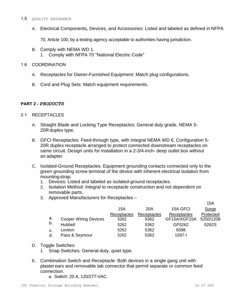
ITD Chemical Storage Building Remodel,
26 27 260
QUALITY ASSURANCE
A. Electrical Components, Devices, and Accessories: Listed and labeled as defined in NFPA
70, Article 100, by a testing agency acceptable to authorities having jurisdiction.
B. Comply with NEMA WD 1. 1. Comply with NFPA 70 "National Electric Code"
COORDINATION
A. Receptacles for Owner-Furnished Equipment: Match plug configurations.
B. Cord and Plug Sets: Match equipment requirements.
PRODUCTS
RECEPTACLES
A. Straight Blade and Locking Type Receptacles: General duty grade, NEMA 5-20R duplex type.
B. GFCI Receptacles: Feed-through type, with integral NEMA WD 6, Configuration 5-
20R duplex receptacle arranged to protect connected downstream receptacles on same circuit. Design units for installation in a 2-3/4-inch- deep outlet box without an adapter.
C. Isolated-Ground Receptacles: Equipment grounding contacts connected only to the
green grounding screw terminal of the device with inherent electrical isolation from mounting strap. 1. Devices: Listed and labeled as isolated-ground receptacles. 2. Isolation Method: Integral to receptacle construction and not dependent on
removable parts. 3. Approved Manufacturers for Receptacles –
15A 15A
Receptacles 20A
Receptacles 15A GFCI
Receptacles Surge
Protected Cooper Wiring Devices 5262 5362 GF15A/XGF15A 5250/1208 Hubbell 5262 5362 GF5262 5262S Leviton 5262 5362 6598 Pass & Seymour 5262 5362 1597-I
D. Toggle Switches:
1. Snap Switches: General-duty, quiet type.
E. Combination Switch and Receptacle: Both devices in a single gang unit with plaster ears and removable tab connector that permit separate or common feed connection.
Switch: 20 A, 120/277-VAC.

ITD Chemical Storage Building Remodel,
26 27 260
Receptacle: NEMA WD 6, Configuration 5-15R. 2. Where more than one switch occurs at the same location, they shall be
ganged under one plate. Where space does not permit horizontal ganging, interchangeable type switches may be used, only with approval of the Owner’s Representative.
3. Approved Manufacturers for Switches - 15A
15A Switches
20A Switches
Three-Way Switches
Cooper Wiring Devices 1201 AH1221 1203 Hubbell HBL1201 HBL1221 HBL1203 Leviton 1201 1202 1203 Pass & Seymour 15AC-1 20AC-1 15AC-3
ITD Chemical Storage Building Remodel,
26 27 260
WALL PLATES
A. Single and combination types match corresponding wiring devices. 1. Plate-Securing Screws: Metal with head color to match plate finish. 2. Provide plates for all devices and outlets with opening configuration suitable for
devices to be covered. 3. Plates shall be smooth urea plastic secured in place with screws finished to
match the plates. Back of the house areas, such as equipment spaces, shall have steel plates. Stainless steel plates shall be used in kitchens. In use rated weatherproof plates shall be used where exposed to the weather.
4. Color: White
Color of devices shall match cover plates.
EXECUTION
INSTALLATION
A. Install devices and assemblies plumb and secure.
B. Protect devices and assemblies during painting. Install wall plates when painting is complete.
C. Install wall dimmers to achieve indicated rating after derating for ganging as
instructed by manufacturer.
D. Do not share neutral conductor on load side of dimmers.
E. Arrangement of Devices: Unless otherwise indicated, mount flush, with long dimension vertical, and grounding terminal of receptacles on top. Group adjacent switches under single, multi-gang wall plates.
F. Adjust locations at which floor service outlets and telephone/power service
poles are installed to suit arrangement of partitions and furnishings.
IDENTIFICATION
A. Comply with Section 26 05 53 "Identification for Electrical Systems." 1. Switches: Where three or more switches are ganged, and elsewhere as
indicated, identify each switch with approved legend engraved on wall plate.
2. Receptacles: Identify panelboard and circuit number from which served. Use machine- printed, pressure-sensitive, abrasion-resistant label tape on face of plate and durable wire markers or tags within outlet boxes.
CONNECTIONS
A. Connect wiring device grounding terminal to branch-circuit equipment grounding conductor.
ITD Chemical Storage Building Remodel,
26 27 260
B. Isolated-Ground Receptacles: Connect to isolated-ground conductor routed to designated isolated equipment ground terminal of electrical system.
C. Tighten electrical connectors and terminals according to manufacturer’s published
torque-tightening values. If manufacturers torque values are not indicated, use those specified in UL 486A and UL 486B.
FIELD QUALITY CONTROL
A. Test wiring devices for proper polarity and ground continuity. Operate each device at least six times.
B. Check TVSS receptacle indicating lights for normal indication.
C. Test GFCI operation with both local and remote fault simulations according to
manufacturer's written instructions.
D. Replace damaged or defective components.
CLEANING
A. Internally clean devices, device outlet boxes, and enclosures. Replace stained or improperly painted wall plates or devices.
END OF SECTION
ITD Chemical Storage Building Remodel,
26 51 00
SECTION 26 51 00
INTERIOR LIGHTING
GENERAL
SUMMARY
A. Section Includes: 1. Interior Lighting Fixtures 2. Exit Signs 3. Emergency Lighting Units 4. Accessories
REFERENCES
A. American National Standards Institute (ANSI) Publications: 1. C82.4 “Ballasts for High – Intensity – Discharge and Low Pressure Sodium
Lamps (Multiple-Supply Type)”
B. Institute of Electrical and Electronics Engineers, Inc. (IEEE) Publications: 1. C62.41 “Surge Voltages in Low-Voltage AC Power Circuits”
C. National Fire Protection Association (NFPA) Publications:
1. NFPA 70 "National Electric Code" 2. NFPA 101 “Life Safety Code®”
D. Underwriter's Laboratories, Inc. (UL) Publications:
1. 486A “Standard For Wire Connectors and Soldering Lugs for Use with Copper Conductors”
2. 486B “Standard for Wire Connectors for Use with Aluminum Conductors” 3. 924 “Emergency Lighting and Power Equipment”
PRIOR APPROVAL
A. General: 1. Catalog and manufacturer's numbers are for the purpose of establishing
standards of quality and types of materials to be used. Products of other manufacturers may be used if equal in quality and design in the opinion of the Engineer and are specifically approved by the Engineer, in writing, 10 days prior to close of bidding.
2. Any conflict arising from the use of substituted equipment shall be the responsibility of the supplier of that equipment. The contractor and his supplier shall bear all costs required to make equipment comply with the intent of the plans and specifications.
SUBMITTALS
A. General: Submit the following in accordance with Conditions of Contract and Division 01 Specification Sections: 1. For each type of lighting fixture indicated, arranged in order of fixture
designation. Include data on features, accessories, and the following:
ITD Chemical Storage Building Remodel,
26 51 00
Dimensions of fixtures. Certified results of laboratory tests for fixtures and lamps for photometric
performance. Emergency lighting unit battery and charger. Photometric data.
2. Field Test Reports: Indicate and interpret test results for compliance with performance requirements.
3. Maintenance Data: For lighting fixtures to include in maintenance manuals specified in Division 01.
QUALITY ASSURANCE
A. Fixtures, Emergency Lighting Units, and Accessories: Listed and labeled as defined in NFPA 70, Article 100, by a testing agency acceptable to authorities having jurisdiction.
B. Comply with NFPA 70.
C. NFPA 101 Compliance: Comply with visibility and luminance requirements for exit signs.
COORDINATION
A. Fixtures, Mounting Hardware, and Trim: Coordinate layout and installation of lighting fixtures with ceiling system and other construction.
EXTRA MATERIALS
A. Deliver extra materials to Owner. Furnish extra materials described in Division 01 Section that match products installed, are packaged with protective covering for storage, and are identified with labels describing contents.
PRODUCTS
FIXTURES AND FIXTURE COMPONENTS, GENERAL
A. Approved Manufacturers: 1. Subject to compliance with requirements, provide the products indicated
for each designation in Lighting Fixture Schedule as shown on drawings. 2. All alternate light fixture packages shall be submitted a minimum of 10 days
prior to bid for approval.
B. Metal Parts: Free from burrs, sharp corners, and edges.
C. Sheet Metal Components: Steel, unless otherwise indicated. Form and support to prevent warping and sagging.
D. Doors, Frames, and Other Internal Access: Smooth operating, free from light leakage
under operating conditions, and arranged to permit relamping without use of tools. Arrange doors, frames, lenses, diffusers, and other pieces to prevent accidental falling during relamping and when secured in operating position.
E. Reflecting Surfaces: Minimum reflectance as follows, unless otherwise indicated:
ITD Chemical Storage Building Remodel,
26 51 00
1. White Surfaces: 85 percent. 2. Specular Surfaces: 83 percent. 3. Diffusing Specular Surfaces: 75 percent. 4. Laminated Silver Metallized Film: 90 percent.
F. Lenses, Diffusers, Covers, and Globes: 100 percent virgin acrylic plastic or annealed
crystal glass, unless otherwise indicated. 1. Plastic: High resistance to yellowing and other changes due to aging, exposure
to heat, and ultraviolet radiation. 2. Lens Thickness: 0.125 inch minimum, unless greater thickness is indicated.
LED LIGHTING FIXTURES
A. General Requirements: 1. See lighting fixtures schedule for specifications.
EXIT SIGNS
A. General Requirements: Comply with UL 924 and the following: 1. Sign Colors and Lettering Size: Comply with authorities having jurisdiction.
B. Internally Lighted Signs: As follows:
1. Lamps for AC Operation: Light-emitting diodes, 70,000 hours minimum rated lamp life.
C. Self-Powered Exit Signs (Battery Type): Integral automatic charger in a self-
contained power pack. 1. Battery: Sealed, maintenance-free, nickel-cadmium type with special warranty. 2. Charger: Fully automatic, solid-state type with sealed transfer relay. 3. Operation: Relay automatically energizes lamp from unit when circuit voltage
drops to 80 percent of nominal or below. When normal voltage is restored, relay disconnects lamps, and battery is automatically recharged and floated on charger.
EMERGENCY LIGHTING UNITS
A. General Requirements: Self-contained units. Comply with UL 924. Units include the following features: 1. Battery: Sealed, maintenance-free, lead-acid type with minimum 10-year
nominal life and special warranty. 2. Charger: Fully automatic, solid-state type with sealed transfer relay. 3. Operation: Relay automatically turns lamp on when supply circuit voltage drops
to 80 percent of nominal voltage or below. Lamp automatically disconnects from battery when voltage approaches deep-discharge level. When normal voltage is restored, relay disconnects lamps, and battery is automatically recharged and floated on charger.
4. Integral Time-Delay Relay: Arranged to hold unit on for fixed interval after restoring power after an outage. Provides adequate time delay to permit high-intensity-discharge lamps to restrike and develop adequate output.
FIXTURE SUPPORT COMPONENTS
A. Comply with Section 26 05 00 "Common Work Results for Electrical”.
ITD Chemical Storage Building Remodel,
26 51 00
B. Single-Stem Hangers: 1/2-inch steel tubing with swivel ball fitting and ceiling canopy.
Finish same as fixture.
C. Twin-Stem Hangers: Two, 1/2-inch steel tubes with single canopy arranged to mount a single fixture. Finish same as fixture.
D. Rod Hangers: 3/16-inch- minimum diameter, cadmium-plated, threaded steel rod.
E. Hook Hangers: Integrated assembly matched to fixture and line voltage and
equipped with threaded attachment, cord, and locking-type plug.
F. Aircraft Cable Support: Use cable, anchorages, and intermediate supports recommended by fixture manufacturer.
FINISHES
A. Fixtures: Manufacturer's standard, unless otherwise indicated. 1. Paint Finish: Applied over corrosion-resistant treatment or primer, free of defects. 2. Metallic Finish: Corrosion resistant. 3. Colors as indicated in Light Fixture Schedule.
LAMPS
A. Approved Manufacturers: 1. LED:
See lighting fixture Schedule
B. Color Temperature and Minimum Color-Rendering Index: 4000 K and 85 CRI, unless otherwise indicated.
EXECUTION
INSTALLATION
A. Fixtures: Set level, plumb, and square with ceiling and walls, and secure according to manufacturer's written instructions and approved submittal materials. Install lamps in each fixture.
B. Support for Fixtures in or on Grid-Type Suspended Ceilings:
1. Recessed lighting fixtures shall be supported independently from the suspended ceiling system. Number 8 gauge galvanized steel wire or approved type hangers from the overhead building structures shall be provided for fixture support.
LIGHT FIXTURE ATTACHMENT:
A. Light fixtures (all types) shall be mechanically attached to grid per NEC 410-16 (two per fixture unless independently supported). 1. Surface-mounted fixtures shall be attached to grid. 2. Pendant-hung fixtures shall be directly supported from structure with 9-gauge
wire (or approved alternative).
ITD Chemical Storage Building Remodel,
26 51 00
3. Rigid lay-in or can light fixtures: <10 lbs. - one wire to structure (may be slack). 11 to 56 lbs. - two wires from housing to structure (may be
slack). >57 lbs. - supported directly to structure by approved method.
CONNECTIONS
A. Ground Equipment: 1. Tighten electrical connectors and terminals according to manufacturer's
published torque-tightening values. If manufacturer's torque values are not indicated, use those specified in UL 486A and UL 486B.
FIELD QUALITY CONTROL
A. Inspect each installed fixture for damage. Replace damaged fixtures and components.
B. Advance Notice: Give dates and times for field tests.
C. Provide instruments to make and record test results.
D. Tests: As follows: 1. Verify normal operation of each fixture after installation. 2. Emergency Lighting: Interrupt electrical supply to demonstrate proper operation. 3. Verify normal transfer to battery source and retransfer to normal. 4. Report results in writing.
E. Malfunctioning Fixtures and Components: Replace or repair, then retest. Repeat
procedure until units operate properly.
F. Corrosive Fixtures: Replace during warranty period.
CLEANING AND ADJUSTING
A. Clean fixtures internally and externally after installation. Use methods and materials recommended by manufacturer.
END OF SECTION
ITD Chemical Storage Building Remodel,
27 05 33
SECTION 27 05 33
CONDUITS AND BACKBOXES FOR COMMUNICATIONS SYSTEMS
GENERAL
SUMMARY
A. Section includes conduit and tubing, surface raceways, wire ways, outlet boxes, pull and junction boxes, and hand holes.
REFERENCES
A. American National Standards Institute: 1. ANSI C80.1 - Rigid Steel Conduit, Zinc Coated 2. ANSI C80.3 - Specification for Electrical Metallic Tubing, Zinc Coated
B. National Electrical Manufacturers Association:
1. NEMA 250 - Enclosures for Electrical Equipment (1000 Volts Maximum) 2. NEMA FB 1 - Fittings, Cast Metal Boxes, and Conduit Bodies for Conduit
and Cable Assemblies 3. NEMA OS 1 - Sheet Steel Outlet Boxes, Device Boxes, Covers, and Box Supports 4. NEMA OS 2 - Nonmetallic Outlet Boxes, Device Boxes, Covers, and Box Supports
SYSTEM DESCRIPTION
A. Raceway and boxes located as indicated on Drawings, and at other locations required for splices, taps, wire pulling, equipment connections, and compliance with regulatory requirements. Raceway and boxes are shown in approximate locations unless dimensioned. Provide raceway to complete wiring system.
B. Concealed Dry Locations: Provide electrical metallic tubing and nonmetallic
conduit. Provide sheet-metal boxes. Provide flush mounting outlet box in finished areas.
C. Exposed Dry Locations: Provide electrical metallic tubing and nonmetallic conduit.
Provide sheet-metal boxes. Provide flush mounting outlet box in finished areas.
DESIGN REQUIREMENTS
A. Minimum Raceway Size: 3/4 inch unless otherwise specified.
PRIOR APPROVAL
A. General: 1. Catalog and manufacturer's numbers are for the purpose of establishing
standards of quality and types of materials to be used. Products of other manufacturers may be used if equal in quality and design in the opinion of the Engineer and are specifically approved by the Engineer, in writing, 10 days prior to close of bidding.
2. Any conflict arising from the use of substituted equipment shall be the responsibility of the supplier of that equipment. The contractor and his supplier shall bear all costs required to make equipment comply with the intent of the

ITD Chemical Storage Building Remodel,
27 05 33
plans and specifications.
SUBMITTALS
A. Section 01 33 00 - Submittal Procedures: Submittal procedures. B. Product Data: Submit for the following:
1. Electrical metallic tubing 2. Surface raceway
C. Manufacturer's Installation Instructions: Submit application conditions and
limitations of use stipulated by Product testing agency specified under Regulatory Requirements. Include instructions for storage, handling, protection, examination, preparation, and installation of Product.
CLOSEOUT SUBMITTALS
A. Section 01 70 00 - Execution and Closeout Requirements: Requirements for submittals.
B. Project Record Documents: 1. Record actual locations and mounting heights of outlet, pull, and junction boxes.
DELIVERY, STORAGE, AND HANDLING
A. Section 01 60 00 - Product Requirements: Product storage and handling requirements.
B. Protect conduit from corrosion and entrance of debris by storing above grade. Provide appropriate covering.
COORDINATION
A. Section 01 30 00 - Administrative Requirements: Coordination and project conditions.
B. Coordinate installation of outlet boxes for equipment connected under Section 26 05 33.
C. Coordinate mounting heights, orientation and locations of outlets mounted above counters, benches, and backsplashes.
PRODUCTS
ELECTRICAL METALLIC TUBING (EMT)
A. Product Description: ANSI C80.3; galvanized tubing.
B. Fittings and Conduit Bodies: NEMA FB 1; steel compression type.
SURFACE METAL RACEWAY
A. Manufacturers: 1. Carlon Electrical Products 2. Hubbell Wiring Devices 3. Thomas & Betts Corp. 4. Walker Systems Inc.
ITD Chemical Storage Building Remodel,
27 05 33
5. The Wiremold Co.
B. Product Description: Sheet metal channel with fitted cover, suitable for use as surface metal raceway.
SURFACE NONMETAL RACEWAY
A. Manufacturers: 1. Carlon Electrical Products 2. Hubbell Wiring Devices 3. Thomas & Betts Corp. 4. Walker Systems Inc. 5. The Wiremold Co.
B. Product Description: Fiberglass channel with fitted cover, suitable for use as
surface raceway.
C. Finish: Ivory
D. Fittings, Boxes, and Extension Rings: Furnish manufacturer's standard accessories, finish to match raceway.
OUTLET BOXES
A. Sheet Metal Outlet Boxes: NEMA OS 1, galvanized steel. 1. Luminaire and Equipment Supporting Boxes: Rated for weight of equipment
supported; furnish 1/2 inch male fixture studs where required. 2. Concrete Ceiling Boxes: Concrete type.
B. Wall Plates for Finished Areas: As specified in Section 26 27 26.
EXECUTION
EXAMINATION
A. Section 01 30 00 - Administrative Requirements: Coordination and project conditions.
B. Verify outlet locations and routing and termination locations of raceway prior to rough-in.
EXISTING WORK
A. Remove exposed abandoned raceway. Cut raceway flush with walls and floors, and patch surfaces.
B. Remove concealed abandoned raceway to its source.
C. Disconnect abandoned outlets and remove devices. Remove abandoned outlets
when raceway is abandoned and removed. Install blank cover for abandoned outlets not removed.
D. Maintain access to existing boxes and other installations remaining active and
requiring access. Modify installation or provide access panel.
ITD Chemical Storage Building Remodel,
27 05 33
E. Extend existing raceway and box installations using materials and methods as specified.
F. Clean and repair existing raceway and boxes to remain or to be reinstalled.
INSTALLATION
A. Install Work in accordance with standards.
B. Identify raceway and boxes in accordance with Section 26 05 53.
C. Arrange raceway and boxes to maintain headroom and present neat appearance. INSTALLATION - RACEWAY
A. Raceway routing is shown in approximate locations unless dimensioned. Route to
complete wiring system.
B. Arrange raceway supports to prevent misalignment during wiring installation.
C. Support raceway using coated steel or malleable iron straps, lay-in adjustable hangers, clevis hangers, and split hangers.
D. Do not support raceway with wire or perforated pipe straps. Remove wire
used for temporary supports
E. Do not attach raceway to ceiling support wires or other piping systems.
F. Construct wire way supports from steel channel specified in Section 26 05 29.
G. Route exposed raceway parallel and perpendicular to walls.
H. Route raceway installed above accessible ceilings parallel and perpendicular to walls.
I. Maintain clearance between raceway and piping for maintenance purposes.
J. Maintain 12-inch clearance between raceway and surfaces with temperatures exceeding 104 degrees F.
K. Cut conduit square using saw or pipe cutter; de-burr cut ends.
L. Bring conduit to shoulder of fittings; fasten securely.
M. Install no more than equivalent of three 90-degree bends between boxes. Install
conduit bodies to make sharp changes in direction, as around beams.
INSTALLATION - BOXES
A. Owner to install all rough-in boxes for data cabling.
INTERFACE WITH OTHER PRODUCTS
A. Install conduit to preserve fire resistance rating of partitions and other elements.
CLEANING
ITD Chemical Storage Building Remodel,
27 05 33
A. Clean interior of boxes to remove dust, debris, and other material.
B. Clean exposed surfaces and restore finish.
END OF SECTION
ITD Chemical Storage Building Remodel,
27 10 00 -
SECTION 27 10 00
TELECOMMUNICATIONS STRUCTURED CABLING
GENERAL
RELATED DOCUMENTS
A. Drawings and general provisions of the Contract, including General and Supplementary Conditions and Division 1 Specification Sections, apply to this Section.
SUMMARY
A. Section Includes: 1. UTP cabling. 2. 8.3/125-micrometer optical fiber cabling. 3. Cable connecting hardware, patch panels, and cross-connects. 4. Telecommunications outlet/connectors. 5. Cable management system. 6. Cabling identification products. 7. Backboards. 8. Telecommunications equipment racks and cabinets. 9. Grounding. 10. Pathways. 11. Telecommunications mounting elements.
B. Related Sections:
1. Division 26 05 26 “Grounding and Bonding for Communications Systems for voice and data cabling associated with system panels and devices.
C. Bidding Requirements:
1. Bidder shall submit complete detailed proposals with line item cost representation for components and associated installation labor. Lump sum bids will not be accepted.
2. Bidders shall include as part of the bid response the following items: Installation schedule with proposed manpower assignments. Resumes for project manager and lead technician for this project. BICSI RCDD certificate and registration number.
3. Bidders shall review associated electrical, telecommunications infrastructure drawings to verify that necessary conduit and floor boxes will be provided by others. Bidders shall understand and coordinate shared infrastructure locations for telecommunications outlets. The Owner will provide no additional infrastructure to support the telecommunications cabling systems Inside Plant (ISP) and Outside Plant (OSP). Any discrepancies with the identified infrastructure to support these systems should be questioned in the form of a request for information (RFI) during the bidding process. Be responsible for any additional infrastructure requirements after receipt of contract for this project. Unless specifically stated, no wiremold-style or surface mounted raceways shall be approved on this project.
4. Unspecified Equipment and Material: Any item of equipment or material not specifically addressed on the drawings or in this document and required to

ITD Chemical Storage Building Remodel,
27 10 00 -
provide complete and functional Structured Cabling System shall be provided in a level of quality consistent with other specified items.
ABBREVIATIONS USED
A. B.
10G 10GPON
10-Gigabit Ethernet 10-Gigabit Symmetrical Passive Optical Network
C. A/V Audio Visual
D. AC Alternating Current
E. ADN Area Distribution Node
F. APC Angled Physical Contact
G. BICSI Building Industry Consulting Services International
H. DC Direct Current
I. EF Entrance Facility
J. EUB End User Building
K. ER Equipment Room
L. Gbe Gigabit Ethernet
M. GPON Gigabit Passive Optical Network
N. IDC Insulation Displacement Connector
O. IDF Intermediate Distribution Frame
P. ITU International Telecommunications Union
Q. ISP Inside Plant Wiring
R. JHA Jurisdiction Having Authority
S. LAN Local Area Network
T. MCN Main Core Node
U. MDF Main Distribution Frame
ITD Chemical Storage Building Remodel,
27 10 00 -
V. NMCI Navy Marine Corps Intranet
W. ODN Optical Distribution Network
X. OLT Optical Line Terminal
Y. ONT Optical Network Terminal
Z. OSP Outside Plant Wiring
AA. PDS Protective Distribution System
BB. PDU Power Distribution Unit (ONT Remote Powering)
ITD Chemical Storage Building Remodel,
27 10 00 -
CC. PoE Power over Ethernet, 15.4W
DD. PoE+ Power over Ethernet Plus; 25.5W
EE. POL Passive Optical LAN
FF. RCDD Registered Communications Distribution
Designer GG. RU Rack Unit
HH. SFP Small Form Pluggable
II. SMF Single Mode Fiber
JJ. TDMM BICSI Telecommunications Distribution Methods
Manual KK. UPC Ultra Physical Contact
LL. TR Telecommunications
Room MM.WAO
Work Area Outlet
SYSTEM DESCRIPTION
A. Provide a complete and functioning structured cabling system inclusive of all hardware, software and training to meet or exceed the performance features outlined in this document.
B. Horizontal cable and its connecting hardware provide the means of transporting
signals between the telecommunications outlet/connector and the horizontal cross-connect located in the communications equipment room. This cabling and its connecting hardware are called "permanent link," a term that is used in the testing protocols. 1. TIA/EIA-568-C.1 requires that a minimum of two telecommunications
outlet/connectors be installed for each work area. 2. Horizontal cabling shall contain no more than one transition point or
consolidation point between the horizontal cross-connect and the telecommunications outlet/connector.
3. Bridged taps and splices shall not be installed in the horizontal cabling. 4. Optical splitters shall be installed as part of the optical fiber cabling permanent
link and included in all permanent link test reports.
C. The maximum allowable horizontal cable length for category rated copper cabling is 295 feet. This maximum allowable length does not include an allowance for the length of 16 feet to the workstation equipment. The maximum allowable length does not include an allowance for the length of 16 feet in the horizontal cross-connect.
D. Backbone cabling system shall provide interconnections between communications
ERs, MDFs, and EFs in the telecommunications cabling system structure. Cabling system consists of backbone cables, intermediate and main cross-connects, mechanical terminations, and patch cords or jumpers used for backbone-to-

ITD Chemical Storage Building Remodel,
27 10 00 -
backbone cross- connection and backbone to zone cross-connection points.
PERFORMANCE REQUIREMENTS
A. General Performance: The cabling system shall comply with transmission standards in TIA/EIA-568-C.1, when tested according to test procedures of this standard.
SUBMITTAL REQUIREMENTS
A. Comply with requirements of Section 01 33 00 - Submittal Procedures.
B. Submittal data is to be submitted in a three ring binder, a continuous spiral binder, or plastic binding that allows the booklet to lie flat while open. Each booklet shall contain the below in the following order: 1. Cover Sheet (including name of supplying contractor, project name, and
project manager contact information) 2. Detailed List of Materials
Include a catalog sheet per product of equipment listed in the detailed bill of materials, in the exact order as the detailed bill of materials. Each catalog sheet shall describe mechanical, electrical and functional equipment specifications. The catalog sheet must also include a image of the product. Photocopy duplications of the manufacturer’s original equipment catalog sheets will be allowed as long as they provide adequate clarity of both the printed word and graphics/pictures. If more than one product is shown on the catalog sheet the intended product must be denoted by either an arrow or highlight.
3. Authorized Distribution/Reseller Certificate Recently dated (within one year from submittal date) support letter from manufacturer stating that the supplying contractor is an authorized distributor of the product being supplied.
4. Prequalification Warrantee Recently dated (within one year from submittal date) support letter from manufacturer stating that the supplying contractor is authorized to obtain for the owner the Special Warranty for Cabling System and the Special Warranty for System Assurance.
5. Prequalification Certificate Copy of the installing technician(s) certificate of completion from the manufacturer’s training school for the equipment being provided.
C. Shop Drawings are to be submitted on project standard full size and bound.
Each shop drawing set is to include the below in the following order: 1. Title Sheet.
Containing, at a minimum, a list of all drawings in the set and a symbols legend defining each symbol used in the package.
2. Riser Diagram. Show the relationship of TR’s, the pathway between them, and cable connectivity to be installed.
3. Typical Outlet Details. Detail each typical outlet type to be installed. Include manufacturer specific plates, jacks, and an example of labeling. Note on the drawing the typical application of each outlet type, for example; standard office, computer lab, ceiling mounted wireless access location, etc.
4. Floor Plans. Show planned location for all elements and cable routing. Drawings should be at project standard scale clearly legible. Include outlet port numbers for each outlet.
ITD Chemical Storage Building Remodel,
27 10 00 -
QUALITY ASSURANCE
A. Installer Qualifications: Cabling Installer must have personnel certified by BICSI on staff. 1. Layout Responsibility: Preparation of shop drawings and cabling
administration drawings by an RCDD. 2. Installation Supervision: Installation shall be under the direct supervision of Level
2 Installer and manufactures certified installer, who shall be present at all times when work of this section is performed at project site. One half of remainder of the crew shall be at a minimum registered technicians by manufacture as part of their certified installer program.
B. Surface-Burning Characteristics: As determined by testing identical products
according to ASTM E 84 by a qualified testing agency. Identify products with appropriate markings of applicable testing agency. 1. Flame-Spread Index: 25 or less. 2. Smoke-Developed Index: 50 or less.
C. Electrical Components, Devices, and Accessories: Listed and labeled as defined
in NFPA 70, by a qualified testing agency, and marked for intended location and application.
D. Installing company shall be certified by manufactures in aspects of design,
installation and testing of optical and Category 6 metallic premise distribution systems, be a manufactures Value Added Reseller (VAR) in good standing and have a minimum of five (5) years’ experience on similar Structured Cabling Systems (SCS). Have a Registered Communications Distribution Designer (RCDD) on staff.
E. Telecommunications Pathways and Spaces: Comply with TIA/EIA-569-A.
F. Administration Standard for the Telecommunications Infrastructure of Commercial
Buildings, 2002 ANSI/TIA/EIA – 606
G. Grounding: Comply with ANSI-J-STD-607-A.
H. NFPA 70 – National Electric Code, 2005
I. BICSI – Telecommunications Distribution Methods Manual, 13th Edition, 2014
J. NEMA – VE-1 – Metal Cable Tray Systems, 2002
K. NEMA – VE-2 – Metal Cable Tray Installation Guidelines, 2001
PROJECT CONDITIONS
A. Environmental Conditions: Do not deliver or install cables and connecting materials until wet work in spaces is complete and dry, and temporary HVAC system is operating and maintaining ambient temperature and humidity conditions at occupancy levels during the remainder of the construction period.
B. Environmental Limitations: Do not deliver or install equipment frames and ladder
racking until spaces are enclosed, secured and weather tight, wet work in spaces is complete and dry, and work above ceilings is complete.
ITD Chemical Storage Building Remodel,
27 10 00 -
COORDINATION
A. Coordinate layout and installation of communications equipment with Owner's telecommunications and LAN equipment and service suppliers 1. Meet jointly with telecommunications and LAN equipment suppliers, local
exchange carrier representatives, and Owner to exchange information and agree on details of equipment arrangements and installation interfaces.
2. Record agreements reached in meetings and distribute them to other participants. 3. Adjust arrangements and locations of distribution frames, cross-connects,
and patch panels in equipment rooms to accommodate and optimize arrangement and space requirements of telephone switch and LAN equipment.
4. Adjust arrangements and locations of equipment with distribution frames, cross-connects, and patch panels of cabling systems of other communications, electronic safety and security, and related systems that share space in the equipment room.
B. Coordinate layout and installation of telecommunications pathways and cabling with
Owner's telecommunications and LAN equipment and service suppliers.
C. Coordinate telecommunications outlet/connector locations with location of power receptacles at each work area.
D. Coordinate location of power raceways and receptacles with locations of
communications equipment requiring electrical power to operate
WARRANTY
A. Special Warranty for Cabling System: Manufactures warranty shall ensure against product defects; that approved cabling components exceed the specifications of TIA/EIA 568Cand ISO/IEC IS 11801. The warranty shall apply to passive SCS components. 1. Warranty Period: 25 year cabling system from date of Substantial Completion.
B. Special Warranty for Passive Optical LAN system: Manufactures warranty shall
ensure against product defects and provide maintenance release software upgrades. Warranty shall include advanced order replacement of electronics OLT and ONT components and sub- components, and be provided with 24x7x365 technical assistance center access directly from the manufacturer. On-site support from the manufacturer shall be a 24-hour response time for deemed ‘critical outages’ impacting greater than 10% of the system install base or as necessary by the manufacturer. 1. Warranty Period: one (1) year electronics warranty from date of substantial
completion with options delivered for two (2), three (3) and five (5) year terms in the base bid.
PRODUCTS
MANUFACTURERS
A. In other Part 2 articles where subparagraph titles below introduce lists, the
ITD Chemical Storage Building Remodel,
27 10 00 -
following requirements apply for product selection: 1. Manufacturers: Subject to compliance with requirements, provide products
by the manufacturers specified or as approved equal by the owner.
PATHWAYS
A. General Requirements: Comply with TIA/EIA-569-A.
B. Cable Support: NRTL labeled. Cable support brackets in Telecommunications Rooms shall be designed to prevent degradation of cable performance and pinch points that could damage cable.
C. Provide bend limiters, if not built into the cable support, to maintain cable type
bend radius whenever cable exists pathways or makes transition between two pathways.
CONDUITS AND BOXES
A. Conduit and Boxes: Comply with requirements in Division 26 Section "Raceways and Boxes." Flexible metal conduit shall not be used.
B. No run of conduit shall exceed 100-feet or contain more than 180-degrees in bends and
sweeps without an appropriately sized pull box being inserted.
UTP CABLE
A. Manufacturers: Subject to compliance with requirements, provide products by one of the following available manufacturers offering products that may be incorporated into the Work include, but are not limited to, the following: 1. Panduit Corp 2. Belden 3. Superior Essex 4. Commscope
B. Description: 100-ohm, 4-pair UTP, covered with a blue thermoplastic jacket.
1. 1. Comply with ICEA S-90-661 for mechanical properties. 2. Comply with TIA/EIA-568-B.1 for performance specifications. 3. Comply with TIA/EIA-568-B.2, Category 6. 4. Listed and labeled by an NRTL acceptable to authorities having jurisdiction as
complying with UL 444 and NFPA 70 for the following types: Communications, Plenum Rated: Type CMP, complying with NFPA 262.
OPTICAL FIBER CABLE
A. Provide multimode fiber optic cable meeting the following specifications: 1. Core 50 µm Optical Multimode (OM) 3 or (OM) 4 2. Cladding 125 µm 3. Core- Clad Concentricity ≤ 1.5 µm 4. Attenuation @ 850 nm ≤ 2.3 dB/km Maximum 5. Attenuation @ 1300 nm ≤ 0.6 dB/km Maximum 6. Zero Dispersion Wave Length 1332 nm ≤ 1354 7. Tensile Proof ≥ 100 kpsi 8. Core 62.5 µm 9. Cladding 125 µm

ITD Chemical Storage Building Remodel,
27 10 00 -
10. Core-Clad Concentricity ≤3.0 µm 11. Attenuation @850 nm ≤3.5 dB/km Maximum 12. Attenuation @1300 nm ≤1.0 dB/km Maximum
B. Per industry standards, MMF (multimode fiber) cable plants must maintain
uniform fiber types throughout the operating channel (including fiber link, and any connecting jumpers and/or patch cords).
UTP CABLE HARDWARE
A. Manufacturers: Subject to compliance with requirements, provide products by one of the following available manufacturers offering products that may be incorporated into the Work include, but are not limited to, the following: 1. Panduit Corp 2. Leviton 3. Tripp Lite
B. General Requirements for Cable Connecting Hardware: Comply with TIA/EIA-568-
B.2, IDC type, with modules designed for punch-down caps or tools. Cables shall be terminated with connecting hardware of same category or higher.
C. Data Patch Panel: Modular panels housing multiple-numbered jack units with
IDC-type connectors at each jack for permanent termination of pair groups of installed cables. All patch panels shall be 24 or 48 port. 1. Number of Jacks per Field: One for each four-pair UTP cable indicated conductor
group of indicated cables, plus spares and blank positions adequate to suit specified expansion criteria.
D. Jacks and Jack Assemblies: Modular, color-coded, eight-position eight conductor
modular receptacle units with integral IDC-type terminals. 1. Comply with TIA/EIA-568-B.2, Category 6.
E. Patch Cords: Factory-made, four-pair cables in 3’-20’ in length; terminated with
eight- position modular plug at each end. Patch cords shall have bend-relief-compliant boots and color-coded icons to ensure specified category performance. Patch cords shall have latch guards to protect against snagging.
OPTICAL FIBER CABLE HARDWARE
A. Manufacturers: Subject to compliance with requirements, provide products by one of the following available manufacturers offering products that may be incorporated into the work include, but are not limited to, the following: 1. Corning Optical Communications 2. Approved equal
B. Cross-Connects and Patch Panels: Modular panels housing multiple-numbered,
simplex and duplex cable connectors. 1. Provide Factory assembled pre-terminated drop cable units with six (6) fiber port
molded patch panel units that act as cabinet fiber distribution units (FDU). Only use factory made connectors at patch panels which are fusion spliced to the main cables (pre-made pigtails).
C. Patch Cords: Provide jumper/patch cords meeting the following requirements:
ITD Chemical Storage Building Remodel,
27 10 00 -
1. Factory made 2. Buffered 3. Utilize LC connectors as noted in Section D below. 4. No longer than 10 ft. 5. Contain no splices or mid-length couplers 6. Meet NEC jacking requirements 7. Orange in color for multimode and Yellow in color for single mode.
D. Cable Connecting Hardware:
1. Provide fiber optic connectors meeting EIA/TIA-455-A, EIA/TIA-455-2b, and EIA/TIA- 455-5a, EIA/TIA-455-34, and ANSI/EIA/TIA-568-B.3 standards.
2. Terminate all fiber optic cables with either factory installed or field installed LC (Lucent Connector) type connectors UPC (Ultra Physical Contact). Connectors must have a 0.3 dB maximum insertion loss (Typical) with a connector back reflection (with single-mode fiber) of -40 dB, and a durability of less than 0.3 dB change @ 500 cycles. Use only ceramic ferrules. Connectors must be produced by an ISO 9001 and TL 9000 registered manufacturer. SPC type connectors are not allowed.
TELECOMMUNICATIONS OUTLET/CONNECTORS
A. Manufacturers: Subject to compliance with requirements, provide products by the following available manufacturer offering products that may be incorporated into the Work include : 1. Hubbel 2. No Approved equals
B. Jacks: 100-ohm, balanced, twisted-pair connector; four-pair, eight-position modular.
Comply with TIA/EIA-568-B.1.
C. Workstation Outlets: Provide connector assemblies mounted in single or multi-gang faceplates as shown on contract drawings. 1. Plastic Faceplate: High-impact plastic. Coordinate color with Division 26
Section "Wiring Devices." 2. For use with snap-in jacks accommodating any combination of UTP, optical
fiber, and coaxial work area cords. 3. Legend: Machine printed, desi-window mounted,
Adhesive “sticky-back” labels are not permissible.
FIRE STOP CABLE PASS-THRU SLEEVES
A. Manufacturers: Subject to compliance with requirements, provide products by one of the following available manufacturers offering products that may be incorporated into the Work include, but are limited to, the following: 1. Basis of design: Specified Technologies Inc. 2. Approved equal by:
3M Corporation. Hilti Corporation.
Wiremold- Legrand Corporation.
B. Fire Rated Cable Pathways: STI EZ-PATH Brand device modules comprised of steel raceway with intumescent foam pads allowing 0 to 100 percent cable
ITD Chemical Storage Building Remodel,
27 10 00 -
fill, the following products are acceptable: 1. Specified Technologies Inc. (STI) EZ-PATH Series 44 Fire Rated Pathway 2. Specified Technologies Inc. (STI) EZ-PATH Series 33 Fire Rated Pathway
C. EZ-path series 44 wall sleeves in Telecommunications rooms shall be quantity as
shown on contract drawings.
D. Horizontal cable pathway locations greater than 20 cables fire stop sleeves shall be STI EZ- Path series 33.
E. Horizontal cable pathway locations fewer than 20 cables EMT sleeve with UL listed
system for firestopping is acceptable. Caulks and sealants shall be as manufactured by STI, 3M, Nelson, or approved equivalent.
F. Fill ratio for fire stop EMT sleeves is based on a not to exceed 40% fill capacity.
GROUNDING
A. Comply with requirements in Division 26 Section "Grounding and Bonding" for grounding conductors and connectors.
B. Comply with ANSI-J-STD-607-A
IDF BACKBOARDS
A. Backboards: Plywood, fire-retardant treated, 3/4 by 48 by 96 inches A-C Grade. 1. Provide materials that comply with performance requirements in AWPA C27.
Identify fire-retardant-treated wood with appropriate classification marking of UL, U.S. Testing, Timber Products Inspection, or another testing and inspecting agency acceptable to authorities having jurisdiction.
2. Use treatment for which chemical manufacturer publishes physical properties of treated wood after exposure to elevated temperatures, when tested by a qualified independent testing agency according to ASTM D 5516, for plywood.
EXECUTION
INSTALLATION OF PATHWAYS
A. Comply with TIA/EIA-569-A for pull-box sizing and length of conduit and number of bends between pull points.
B. Comply with requirements in Division 26 Section "Raceways and Boxes" for
installation of conduits and wireways.
C. Install manufactured conduit sweeps and long-radius elbows whenever possible.
D. Pathway Installation in Communications Equipment Rooms: 1. Position conduit ends adjacent to a corner on backboard where a single
piece of plywood is installed, or in the corner of room where multiple sheets of plywood are installed around perimeter walls of room.
2. Install cable trays to route cables if conduits cannot be located in these positions. 3. Secure conduits to backboard when entering room from overhead. 4. Extend conduits 3 inches (76 mm) above finished floor.
ITD Chemical Storage Building Remodel,
27 10 00 -
5. Install metal conduits with grounding bushings and connect with grounding conductor to TGB/TMGB.
WIRING METHODS
A. Wiring Method: Install cables in raceways except within consoles, cabinets, desks, and counters. Conceal raceway and cables accessible ceilings, walls, and floors except in unfinished spaces.
B. Wiring within Enclosures: Bundle, lace, and train cables to terminal points with no
excess and without exceeding manufacturer's limitations on bending radii. Provide and use lacing bars and distribution spools.
INSTALLATION OF CABLES
A. Comply with NECA 1.
B. General Requirements for Cabling: 1. Comply with TIA/EIA-568-B.1. 2. Comply with BICSI ITSIM, Current Edition, "Cable Termination Practices." 3. Install 110-style IDC termination hardware unless otherwise indicated. 4. Terminate conductors; no cable shall contain unterminated elements. Make
terminations only at indicated outlets, terminals, cross-connects, and patch panels.
5. Cables may not be spliced. Secure and support cables at intervals not exceeding 30 inches and not more than 6 inches from cabinets, boxes, fittings, outlets, racks, frames, and terminals.
6. Install lacing bars to restrain cables, to prevent straining connections, and to prevent bending cables to smaller radii than minimums recommended by manufacturer.
7. Bundle, lace, and train conductors to terminal points without exceeding manufacturer's limitations on bending radii, but not less than radii specified in BICSI ITSIM, "Cabling Termination Practices" Chapter. Install lacing bars and distribution spools.
8. Do not install bruised, kinked, scored, deformed, or abraded cable. Do not splice cable between termination, tap, or junction points. Remove and discard cable if damaged during installation and replace it with new cable.
9. Cold-Weather Installation: Bring cable to room temperature before de-reeling. Heat lamps shall not be used for heating.
10. In the communications equipment room, install a 10-foot long service loop on each end of cable.
11. Pulling Cable: Comply with BICSI ITSIM, current edition, "Pulling Cable." Section. Monitor cable pull tensions.
C. UTP Cable Installation:
1. Comply with TIA/EIA-568-B.2. 2. Do not untwist UTP cables more than 1/2 inch from the point of termination to
maintain cable geometry. 3. Terminate patch panels and outlets to a pin/pair assignment as directed by owner.
D. UTP Patch Cords 1. Provide modular cords required to connect LAN switches to
modular jacks on cross connect panel shall be furnished as part of this solicitation.
ITD Chemical Storage Building Remodel,
27 10 00 -
Quantities should be equal to the total number of network outlets. At the Patch panel location provide patch cable lengths as needed for a neat installation utilizing vertical wire managers. At the user outlets provide 10 foot patch cables for each 8 pin modular connector.
E. Group connecting hardware for cables into separate logical fields.
F. Optical Fiber Cable Installation:
1. Comply with TIA/EIA-568-C.3. 2. Cable may be terminated on connecting hardware that is rack, zone enclosure or
cabinet mounted. 3. Fiber shall be installed in innerduct within conduits unless armored. 4. Bend insensitive fiber shall be utilized for all horizontal WAO station drop
assemblies to eliminate conduit, innerduct or other protection requirements. 5. Multiple fibers shall be pulled in the same innerduct whenever possible. 6. Fiber shall be installed in one continuous piece. 7. Any excess fiber shall be coiled neatly and secured to a wall above the
plywood backboard so it is out of the way of normal traffic and is not subject to unusual flexing.
G. Separation from EMI Sources:
1. Comply with BICSI TDMM and TIA/EIA-569-A for separating unshielded copper voice and data communication cable from potential EMI sources, including electrical power lines and equipment.
2. Separation between open Category rated copper cables or Category rated cables in nonmetallic raceways and unshielded power conductors and electrical equipment shall be as follows:
Electrical Equipment Rating Less Than 2 kVA: A minimum of 5 inches. Electrical Equipment Rating between 2 and 5 kVA: A minimum of 12 inches.
Electrical Equipment Rating More Than 5 kVA: A minimum of 24 inches. 3. Separation between Category rated communications cables in grounded
metallic raceways and unshielded power lines or electrical equipment shall be as follows:
Electrical Equipment Rating Less Than 2 kVA: A minimum of 2-1/2 inches. Electrical Equipment Rating between 2 and 5 kVA: A minimum of 6 inches.
Electrical Equipment Rating More Than 5 kVA: A minimum of 12 inches. 4. Separation between Category rated communications cables in grounded
metallic raceways and power lines and electrical equipment located in grounded metallic conduits or enclosures shall be as follows:
Electrical Equipment Rating Less Than 2 kVA: No requirement. Electrical Equipment Rating between 2 and 5 kVA: A minimum of 3 inches. Electrical Equipment Rating More Than 5 kVA: A minimum of 6 inches.
5. Separation between Category rated communications Cables and Electrical Motors and Transformers, 5 kVA or HP and Larger: A minimum of 48 inches.
6. Separation between Category rated communications Cables and Fluorescent Fixtures: A minimum of 5 inches.
7. Separation for optical fiber cabling from electrical sources shall not be of concern, however attempts shall be made to accommodate separate pathways for optical components.
INSTALLATION TELECOMMUNICATIONS ROOMS
ITD Chemical Storage Building Remodel,
27 10 00 -
A. Bundle, lace, and train conductors and cables to terminal points without exceeding manufacturer's limitations on bending radii. Install lacing bars and distribution spools.
B. Bond the shield of any shielded cable to the grounding bus bar in
communications rooms and spaces.
C. Backboards: Install backboards with 96-inch dimension vertical. Butt adjacent sheets tightly, and form smooth gap-free corners and joints.
D. Wall Mounted Equipment Cabinets
1. Assemble cabinet according to manufacturer’s instructions. Verify that equipment mounting rails are sized properly for rack-mount equipment before attaching the rack to the wall.
2. All racks must be attached to the wall using appropriate wall mounting anchors. 3. Cabinets shall be grounded to the TGB using appropriate hardware when
supporting electrical components (remote ONT power sources or rack mounted ONTs) or copper cable terminations. The ground will meet local code requirements and will be approved by the JHA.
4. The equipment load should be evenly distributed and uniform on the rack/cabinets. Place large and heavy equipment towards the bottom of the racks/cabinets. Secure all equipment to the racks/cabinets with equipment mounting screws.
E. Firestopping
1. Comply with requirements in Division 07 Section "Penetration Firestopping." 2. General: Install through-penetration firestop systems in accordance with
Performance Criteria and in accordance with the conditions of testing and classification as specified in the published design.
3. Install modular floor grid system in Telecommunications Rooms as shown on contract drawings.
4. Install EMT sleeve where horizontal cables penetrate a fire or smoke rated wall. 5. Manufacturer’s Instructions: Comply with manufacturer’s instructions for
installation of firestopping products. 6. Comply with TIA/EIA-569-A, Annex A, "Firestopping." 7. Comply with BICSI TDMM, "Firestopping Systems" Article. 8. Any penetrations created for the passage of telecommunications which remains
vacant at the completion of the installation shall be fire stopped.
GROUNDING
A. Install grounding according to BICSI TDMM, "Grounding, Bonding, and Electrical Protection" Chapter.
B. Comply with requirements in Division 26 05 26 “Grounding and Bonding for
Communications Systems” for grounding conductors and connectors.
C. Comply with ANSI-J-STD-607-A.
D. Bond metallic equipment to the grounding bus bar, using not smaller than No. 8 AWG equipment grounding conductor.
ITD Chemical Storage Building Remodel,
27 10 00 -
IDENTIFICATION
A. Identify system components, wiring, and cabling complying with TIA/EIA-606-A. Comply with requirements for identification specified in Division 26 Section "Electrical Identification."
B. B. Comply with requirements in Division 09 Section "Interior Painting" for
painting backboards. For fire-resistant plywood, do not paint over manufacturer's label.
C. C. Cable Schedule: Post in prominent location in each equipment room and wiring
closet. List incoming and outgoing cables and their designations, origins, and destinations. Protect with rigid frame and clear plastic cover. Furnish an AutoCad electronic copy of final comprehensive schedules for Project.
D. D. Cabling Administration Drawings: Show building floor plans with cabling
administration- point labeling. Identify labeling convention and show labels for telecommunications closets, backbone pathways and cables, entrance pathways and cables, terminal hardware and positions, horizontal cables, work areas and workstation terminal positions, grounding buses and pathways, and equipment grounding conductors. Follow convention of TIA/EIA-606-A. Furnish AutoCad - latest version -electronic record of all drawings.
E. Cable and Wire Identification:
1. Label each cable within 4 inches of each termination, where it is accessible in a cabinet or junction or outlet box, and elsewhere as indicated.
2. Each wire connected to building-mounted devices is not required to be numbered at device if color of wire is consistent with associated wire connected and numbered within panel or cabinet.
3. Exposed Cables and Cables in Cable Trays and Wire Troughs: Label each cable at intervals not exceeding 15 feet.
4. Label each terminal strip and screw terminal in each cabinet, rack, or panel for remote ONT power low voltage copper pairs
Individually number wiring conductors connected to terminal strips, and identify each cable or wiring group being extended from a panel or cabinet to a building- mounted device shall be identified with name and number of particular device as shown.
Each low voltage copper pair shall designate the closet/rack/zone number and binding position on both ends of the pair.
5. Identification within Connector Fields in Equipment Rooms and Wiring Closets: Label each connector and each discrete unit of cable-terminating and connecting hardware. Where similar jacks and plugs are used for both voice and data communication cabling, use a different color for jacks and plugs of each service.
F. Labels shall be preprinted or computer-printed type with printing area and font
color that contrasts with cable jacket color but still complies with requirements in TIA/EIA-606-A. 1. Cables use flexible vinyl or polyester that flex as cables are bent.
SOURCE QUALITY CONTROL
A. Factory test UTP and optical fiber cables on reels according to TIA/EIA-568-B.1.
ITD Chemical Storage Building Remodel,
27 10 00 -
B. Factory test UTP cables according to TIA/EIA-568-C.2.
C. Factory test single mode optical fiber cables according to TIA/EIA-526-7 and TIA/EIA-568- C.3.
D. Factory-sweep test coaxial cables at frequencies from 5 MHz to 1 GHz. Sweep
test shall test the frequency response, or attenuation over frequency, of a cable by generating a voltage whose frequency is varied through the specified frequency range and graphing the results.
E. Cable will be considered defective if it does not pass tests and inspections.
F. Prepare test and inspection reports.
FIELD QUALITY CONTROL
A. Perform tests and inspections.
B. Tests and Inspections: 1. Visually inspect UTP, multi-pair copper and optical fiber cable jacket materials for
NRTL certification markings. Inspect cabling terminations in communications equipment rooms for compliance with color-coding for pin assignments, and inspect cabling connections for compliance with TIA/EIA-568-C.
2. Visually confirm cable category marking of outlets, cover plates, outlet/connectors, and patch panels.
3. Visually inspect cable placement, cable termination, grounding and bonding, equipment and patch cords, and labeling of all components.
4. Test UTP copper cabling for DC loop resistance, shorts, opens, intermittent faults, and polarity between conductors. Test operation of shorting bars in connection blocks. Test cables after termination but not cross-connection.
Test instruments shall meet or exceed applicable requirements in TIA/EIA-568- C.2. Perform tests with a tester that complies with performance requirements in "Test Instruments (Normative)" Annex, complying with measurement accuracy specified in "Measurement Accuracy (Informative)" Annex. Use only test cords and adapters that are qualified by test equipment manufacturer for channel or link test configuration.
5. Optical Fiber Cable Tests: Optical Loss Testing. Test singlemode backbone links at 1310 nm and 1550 nm in accordance with ANSI/TIA/EIA-526-7-A, Method A.1, One Reference Jumper or the equivalent method. Test multimode Fiber Cable plant in accordance with ANSI/TIA/EIA-526-14-C.
Test fiber links for anomalies and to ensure uniformity of cable attenuation and connector insertion loss. Test singlemode at 1310 nm and 1550 nm, and multimode at 850 nm and 1300 nm. Test each fiber link and channel in both directions. Install a launch cable between the OTDR and the first link connection. Install a receive cable after the last link connection. Inspect fibers at 250X or 400X magnification. 250X magnification is suitable for inspecting singlemode fibers. 400X magnification may be used for detailed examination of singlemode fibers. Measure and record the length of each fiber using either an OLTS or OTDR. Test paired duplex fibers in multi-fiber cables to verify polarity in accordance with Clause E.5.3 of ANSI/TIA-568-C.0 using an OLTS. Acceptance of Test Results. Calculate the link attenuation using the following formulas as specified in ANSI/TIA-568-C.0:

ITD Chemical Storage Building Remodel,
27 10 00 -
1) Link Attenuation (dB) = Cable_Attn (dB) + Connector_Attn (dB) + Splice_Attn (dB)
2) Cable_Attn (dB) = Attenuation_Coefficient (dB/km) * Length (Km) 3) Connector_Attn (dB) = number_of_connector_pairs * connector_loss (dB) 4) Maximum allowable connector_loss = 0.75 dB 5) Splice_Attn (dB) = number_of_splices * splice_loss (dB) 6) Maximum allowable splice_loss = 0.3 dB The values for the Attenuation_Coefficient (dB/km) are listed in the table below:
Type of Optical Fiber Wavelength (nm)
Attenuation coefficient (dB/km)
Wavelength (nm)
Attenuation coefficient (dB/km)
Single-mode (Inside plant) 1310 1.0 1550 1.0 Single-mode (Outside plant)
1310 0.5 1550 0.5
Multimode 62.5/125 µm 850 3.5 1300 1.5 Multimode 50/125 µm 850 3.5 1300 1.5
Reflective events (connections) do not exceed 0.75 dB. Non-reflective events (splices) do not exceed 0.3 dB. Use magnified endface inspection. Visually inspect fiber connections for endface quality. Diagnose and correct scratched, pitted or dirty connectors. Field-test all installed cabling links and channels. Diagnose, correct and re-test failing links and channels. Document the corrective action as well as the final and passing result of the tests for all links and channels in accordance with Part I Submittals. Submit all documentation in writing including passing tests upon project completion. High bandwidth applications such as 1000Base-SX, 10Base-S, and FC1200 impose stringent channel loss limits. Where practical, certification should consider loss length limits that meet maximum channel (transmitter to receiver) loss. Acceptance of Test Results. Calculate the link attenuation using the following formulas as specified in ANSI/TIA-568-C.0: Provide an Optical Loss Test Set (OLTS) meeting the following criteria: 1) Singlemode optical fiber light source 2) Dual laser light sources with central wavelengths of 1310 nm (±20
nm) and 1550 nm (±20 nm). 3) Output power of -10 dBm minimum 4) Power Meter 5) 1300/1310 nm, and 1550 nm wavelength test capability 6) Power measurement uncertainty of □ 0.25 dB 7) Store reference power measurement. 8) Save at least 100 results in internal memory. 9) Capable of measuring the optical length of the fiber using time-
of-flight techniques 10) PC interface (serial or USB). 11) Acceptable manufacturers:
a) Fluke Networks b) Corning Cabling Systems c) Exfo d) Approved equivalent
Use an Optical Time Domain Reflectometer (OTDR) meeting the following criteria: 1) Singlemode OTDR 2) Wavelengths of 1310 nm (± 25 nm) and 1550 nm (± 3 nm) 3) Event deadzones of 3.5 m maximum at 1310 nm and 1550 nm
ITD Chemical Storage Building Remodel,
27 10 00 -
4) Attenuation deadzones of 10 m maximum at 1310 nm and 12 m maximum at 1550 nm
5) Distance range not less than 10000 m 6) Dynamic range at least 10 dB at 1310 nm and 1550 nm 7) Bright, color transmissive LCD display with backlight 8) Rechargeable Li-Ion battery for 8 hours of normal operation 9) Internal non-volatile memory and removable memory device with at least
16 GB or greater capacity for results storage 10) Serial and USB ports to transfer data to a PC 11) Acceptable manufacturers:
a) Fluke Networks b) Corning Cabling Systems c) Exfo d) Approved equivalent
Provide a Fiber Microscope meeting the following criteria: 1) Magnification of 200X or 400X for endface inspection. 2) 200X magnification is suitable for inspecting singlemode fibers. 3) Use 400X magnification for detailed examination of singlemode fibers. 4) Acceptable manufacturers:
e) Fluke Networks f) Corning Cabling Systems g) Approved equivalent
Document data for each measurement. Data for submittals shall be printed in a summary report that is formatted similar to Table 10.1 in BICSI TDMM, or transferred from the instrument to the computer, saved as text files, and printed and submitted. Remove and replace cabling where test results indicate that they do not comply with specified requirements. End-to-end cabling will be considered defective if it does not pass tests and inspections.
CLEANING
A. At the completion of the system, restore aspects of the project site to its former condition. Remove daily waste and excess materials, rubbish debris, tools and equipment resulting from or used in the services provided under this Contract. Remove trash from all work areas. Do not use dumpsters or trash disposal without prior approval.
END OF SECTION
ITD Chemical Storage Building
32 31 13
DIVISION 32 EXTERIOR IMPROVEMENTS
SECTION 32 31 13 CHAIN LINK FENCES AND GATES
PART 1 GENERAL
1.1 SUMMARY
A. Section Includes:
1. Fence framework, fabric, and accessories. 2. Excavation for post bases. 3. Manual gates and related hardware.
1.2 REFERENCES
A. ASTM International:
1. ASTM A121 - Standard Specification for Zinc-Coated (Galvanized) Steel Barbed Wire.
2. ASTM A123/A123M - Standard Specification for Zinc (Hot-Dip Galvanized) Coatings on Iron and Steel Products.
3. ASTM A153/A153M - Standard Specification for Zinc Coating (Hot-Dip) on Iron and Steel Hardware.
4. ASTM A392 - Standard Specification for Zinc-Coated Steel Chain-Link Fence Fabric.
5. ASTM A491 - Standard Specification for Aluminum-Coated Steel Chain-Link Fence Fabric.
6. ASTM A585 - Standard Specification for Aluminum-Coated Steel Barbed Wire.
7. ASTM A792/A792M - Standard Specification for Steel Sheet, 55% Aluminum- Zinc Alloy-Coated by the Hot-Dip Process.
8. ASTM A1011/A1011M - Standard Specification for Steel, Sheet and Strip, Hot- Rolled, Carbon, Structural, High-Strength Low-Alloy and High-Strength Low-Alloy with Improved Formability.
9. ASTM B429 - Standard Specification for Aluminum-Alloy Extruded Structural Pipe and Tube.
10. ASTM F567 - Standard Practice for Installation of Chain-Link Fence. 11. ASTM F900 - Standard Specification for Industrial and Commercial Swing
Gates. 12. ASTM F1083 - Standard Specification for Pipe, Steel, Hot-Dipped Zinc-
Coated (Galvanized) Welded, for Fence Structures. 13. ASTM F1184 - Standard Specification for Industrial and Commercial
Horizontal Slide Gates.
B. Chain Link Fence Manufacturers Institute: 1. CLFMI - Product Manual.
1.3 SYSTEM DESCRIPTION
A. Fence Height: Six feet nominal.
ITD Chemical Storage Building
32 31 13
B. Line Post Spacing: At intervals not exceeding 10 feet. C. Fence Post and Rail Strength: Conform to ASTM F1043 Standard
Industrial Fence quality. 1.4 SUBMITTALS
A. Section 01 33 00 - Submittal Procedures: Requirements for submittals. B. Shop Drawings: Indicate plan layout, spacing of components, post
foundation dimensions, hardware anchorage, gates, and schedule of components.
C. Product Data: Submit data on fabric, posts, accessories, fittings and hardware. D. Samples: Submit two 12 x 12 inch samples of fence fabric, illustrating
construction and finish. E. Manufacturer's Installation Instructions: Submit installation requirements, bolt
templates, and maintenance schedule. 1.5 CLOSEOUT SUBMITTALS
A. Section 01 70 00 - Execution and Closeout Requirements: Closeout procedures. B. Project Record Documents: Accurately record actual locations of property
perimeter posts relative to property lines and easements. C. Operation and Maintenance Data: Procedures for submittals.
1.6 QUALITY ASSURANCE
A. Supply material in accordance with CLFMI - Product Manual. B. Perform installation in accordance with ASTM F567. C. Perform Work in accordance with Department of Defense National Guard
Facility Standards. 1.7 QUALIFICATIONS
A. Manufacturer: Company specializing in manufacturing Products specified in this
section with minimum three years experience. B. Installer: Company specializing in performing work of this section with
minimum three years documented experience. 1.8 DELIVERY, STORAGE AND HANDLING
A. Section 01 60 00 - Product Requirements: Requirements for transporting,
handling, storing, and protecting products. B. Deliver fence fabric and accessories in packed cartons or firmly tied rolls. C. Identify each package with manufacturer’s name. D. Store fence fabric and accessories in secure and dry place.
ITD Chemical Storage Building
32 31 13
PART 2 PRODUCTS 2.1 MATERIALS AND COMPONENTS
A. Materials and Components: Conform to CLFMI Product Manual for standard
industrial /residential service.
2.2 GATES
A. General:
1. Gate Types, Opening Widths and Directions of Operation: As indicated on Drawings.
2. Factory assemble gates. 3. Design gates for operation by one person.
B. Swing Gates:
1. Fabricate gates to permit 180 degree swing. 2. Gates Construction: ASTM F900 with welded corners. Use of corner
fittings is not permitted. C. Sliding Gates:
1. Framing and Posts: ASTM F1184, Class 2 for internal rollers. 2. Rollers for overhead and cantilever sliding gates: Bearing type.
Furnish non- sealed bearings with grease fitting for periodic maintenance.
3. Secure rollers to post or frame without welding. 2.3 FINISHES
A. Components and Fabric: Galvanized to ASTM A123/A123M for
components; ASTM A153/A153M for hardware; ASTM A392 for fabric; 1.8 min. oz/sq ft coating.
B. Hardware: Galvanized to ASTM A153/A153M, 1.8 min. oz/sq ft coating. C. Accessories: Same finish as framing.
PART 3 EXECUTION 3.1 INSTALLATION
A. Install framework, fabric, accessories and gates in accordance with ASTM
F567 and to match existing fence. B. Set intermediate, terminal, gate, and posts plumb, in concrete footings at
finish grade. Slope top of concrete for water runoff. C. Support gates from gate posts. Do not attach hinged side of gate from building
wall. D. Install gate with fabric and barbed wire overhang to match fence. Install three
hinges on each gate leaf.
ITD Chemical Storage Building
32 31 13
E. Allow footings to cure minimum 7 days before installing fabric and other materials attached to posts.
3.2 ERECTION TOLERANCES
A. Section 01 40 00 - Quality Requirements: Tolerances. B. Maximum Variation From Plumb: 1/4 inch. C. Maximum Offset From Indicated Position: 1 inch.
END OF DIVISION END OF GENERAL REQUIREMENTS