GEOTECHNICAL INVESTIGATION GEOTECHNICAL INVESTIGATION BUDA ...

Investigation report Report Report title Activity number Investigation of hydrocarbon leak at Kårstø on 7 January 2016. 003912029
Classification Public Exempt from publication
Restricted Confidential
Strictly confidential
Summary At 22:16 on 7 January 2016, during normal operations, a gas leak was detected in the Statpipe receiving area at Kårstø. No-one was injured in the incident and the material damage was minor. However, the incident did have escalation potential relating to possible ignition of the gas leak, where parts of a gas-transporting pipe could have been exposed to jet fire and heat radiation. If personnel had been in the proximity of the leak in the event of ignition, this could have caused serious personal injuries and potential fatalities. A nearly complete fracture occurred in an instrument fitting with an interior tube diameter of 9.1 mm. When the leak started, the pressure was around 140 bar. The initial leak rate is estimated to be 1.3 kg/s. The gas leak lasted for 9.5 hours and the leaked volume is estimated to be approx. 22 metric tonnes. The leak occurred due to a fatigue fracture in an instrument fitting (NPT Male adapter ½"). The fatigue fracture was due to a lack of adequate pipe support, in combination with coincidence between the system's natural frequencies and the vortex-shedding frequencies at normal wind speeds. The reason that the leak lasted as long as 9.5 hours was an absence of depressurisation options from the control room for the processing segment where the leak occurred. Parties involved Main group Approved by / date T-L Kjell Arild Anfinsen / 18 August 2016
Investigation group participants Investigation leader Espen Landro Process integrity Bryn A. Kalberg Logistics and emergency preparedness Ole Jacob Næss Construction Eivind Sande Process integrity
Eivind Sande

2

3
Contents 1 Summary ........................................................................................................................... 4 2 Introduction ....................................................................................................................... 4 3 Technical descriptions ...................................................................................................... 6
3.1 The system where the incident occurred .............................................. 6 3.2 Description of the equipment involved in the incident ........................ 8 3.3 Design and bracing of manometer ...................................................... 10 3.4 Follow-up and maintenance ............................................................... 11 3.5 Previous related incidents ................................................................... 11 3.6 Investigations following the incident ................................................. 11
3.6.1 Statoil's investigation report ................................................... 11 3.6.2 DNV-GL materials technology investigation ......................... 12 3.6.3 Summary of the DNV-GL report ........................................... 13 3.6.4 The Petroleum Safety Authority Norway's assessments of findings in the DNV-GL report ........................................................................ 14
4 Sequence of events .......................................................................................................... 14 4.1 Incidents prior to 7 January 2016 ....................................................... 14 4.2 The chain of events on 7 and 8 January 2016 .................................... 15
5 The potential of the incident ........................................................................................... 18 5.1 Actual consequences .......................................................................... 18 5.2 Potential consequences ....................................................................... 18
5.2.1 Potential consequences without ignition ................................ 18 5.2.2 Potential consequences in the case of ignition ....................... 18
6 Observations ................................................................................................................... 18 6.1 Non-conformity .................................................................................. 19
6.1.1 Mechanical support of instrument .......................................... 19 6.1.2 Learning and improvement .................................................... 19 6.1.3 Lack of a plan for depressurisation in an emergency situation19
6.2 Improvement point ............................................................................. 20 6.2.1 Assessment of manometer with associated instrument fittings20 6.2.2 Notification/summoning of 2nd-line emergency response organisation at Kårstø ......................................................................... 21 6.2.3 Fault in P&IDs ........................................................................ 21
6.3 Barriers that did function: ................................................................... 21 7 Other comments .............................................................................................................. 22 8 Discussion concerning uncertainties ............................................................................... 23
8.1 Potential consequences ....................................................................... 23 8.2 Uncertainty in materials technology investigations ........................... 23 8.3 Interior gas-flow technical assessments ............................................. 23
9 The following documents were used as a basis for the investigation: ............................ 23 10 Annexes .......................................................................................................................... 24

4
1 Summary At 22:16 on 7 January 2016, during normal operations, a gas leak was detected in the Statpipe receiving area at Kårstø. No-one was injured in the incident and the material damage was minor. However, the incident had considered potential for harm if the gas leak had ignited. Alarms from several gas detectors caused the initiation of automatic ignition source decoupling for Statpipe and Sleipner at 22:17. In total, five gas detectors triggered high-high alarms while the leak was in progress. Emergency shutdown for the Statpipe rich gas inlet was initiated manually from a CAP panel in the control room by a Statpipe panel operator at 22:27. In addition, the panel operator, in consultation with the shift supervisor, decided to perform a controlled shutdown of the T-100 and T-200 processing trains. The PSA received notification of the incident from Gassco at 22:40. Emergency shutdown valves closed within the (sectionised) Statpipe rich gas inlet, so that no further gas flowed into the section of the plant where the leak was in progress. After sectionising, the Statpipe rich gas inlet contained 48 tonnes of gas at a pressure of approx. 140 bar. There were no automatic/remote-controlled pressure relief valves in this processing segment, and the pressure declined only as a result of the leak until 4:20 on 8 January 2016. The pressure had then dropped to approx. 86 bar. At this time, it was decided to send personnel out into the plant to manually open valves to the flare stack, which helped the pressure to fall more quickly. At 7:14, the pressure had fallen to less than ten bar, and it was assessed to be safe to reset the valves to the downstream segment in the field. After opening these valves, the pressure fell even more quickly. At 7:50, personnel managed to stop the leak by closing two block valves close to the leak site. The leak site was subsequently located to a nearly complete fracture in an instrument fitting with an interior tube diameter of 9.1 mm. The initial leak rate is estimated to be 1.3 kg/s. The gas leak lasted for 9.5 hours and the leaked volume is estimated to be approx. 22 metric tonnes. The leak occurred due to a bilateral fatigue fracture in an instrument fitting (NPT Male adapter ½"). The fatigue fracture was due to a lack of adequate pipe support, in combination with coincidence between the system's natural frequencies and the vortex-shedding frequencies at normal wind speeds. The reason that the leak lasted as long as 9.5 hours was an absence of depressurisation options from the control room for the processing segment where the leak occurred. Three non-conformities and three improvement points were identified as a result of the investigation of the incident.
2 Introduction On Thursday, 7 January 2016, at 22:16, gas was detected in area CA16 at Gassco's Kårstø onshore facility. The leak was located as being related to a manometer connected to the rich
5
gas inlet from Statpipe. On 8 January 2016, the PSA decided to perform its own investigation of the incident. Composition of the investigation group:
Eivind Sande Process integrity, investigation leader Espen Landro Process integrity Ole Jacob Næss Construction Bryn Kalberg Logistics, emergency preparedness
The PSA travelled to Kårstø on 8 January 2016 for initial information gathering and a survey of the leak site. On the same day, a brief meeting was also held with the Police at Aksdal, where we were able to visually inspect the manometer in question and its associated tubing and fittings. Interviews with personnel involved were conducted at Kårstø from 11 to 13 January 2016. A review of documentation was also performed, as well as a new survey of the leak site during this period. In addition, on 19 January 2016, there was a telephone interview connected with the Kårstø Integrity Project (KIP). The PSA held a new meeting at Kårstø on 9 February 2016 for clarifications concerning the process flow diagram and alarm lists from the chain of events. On 18 February 2016, a meeting was held with Parker Hannifin AS at their offices in Stavanger. The manometer and associated instrumentation was handed over to the PSA by the Police on 11 March 2016. The PSA then had a technical damage investigation of the components where the leak occurred performed at DNV-GL's department of materials technology. Parker Hannifin AS and Gassco/Statoil contributed necessary technical information for this investigation. The mandate for the PSA's investigation was as follows:
• To clarify the scope and progression of the incident. • To identify and assess safety and emergency response factors. • To describe actual and potential consequences. • Harm sustained by people, property and the environment. • To evaluate the incident's potential for harm to people, property and the environment. • To identify and describe observations of proximate and underlying causes. • To identify and describe non-conformities with regulatory requirements and
improvements points. • To discuss and describe any uncertainties/unclear issues. • To recommend further follow-up and to propose the use of measures. • To prepare a report and accompanying letter per template. • A timeframe for the task to be agreed after the investigation work at the facility is
completed.
6
3 Technical descriptions
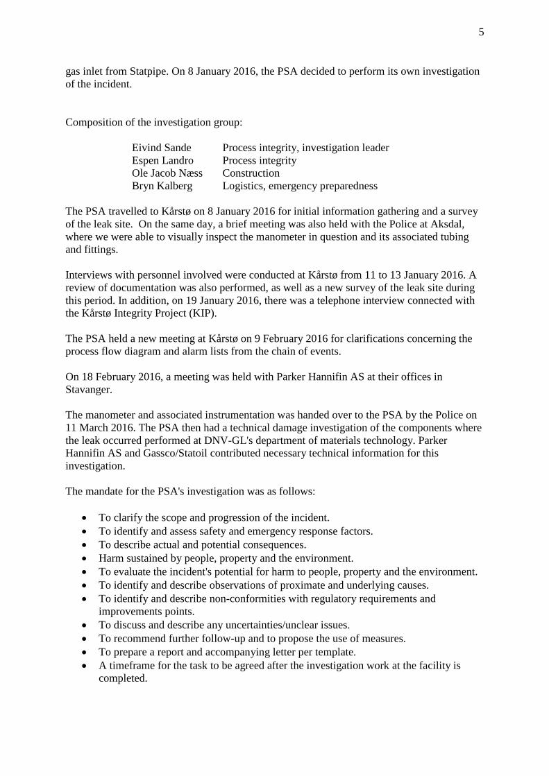
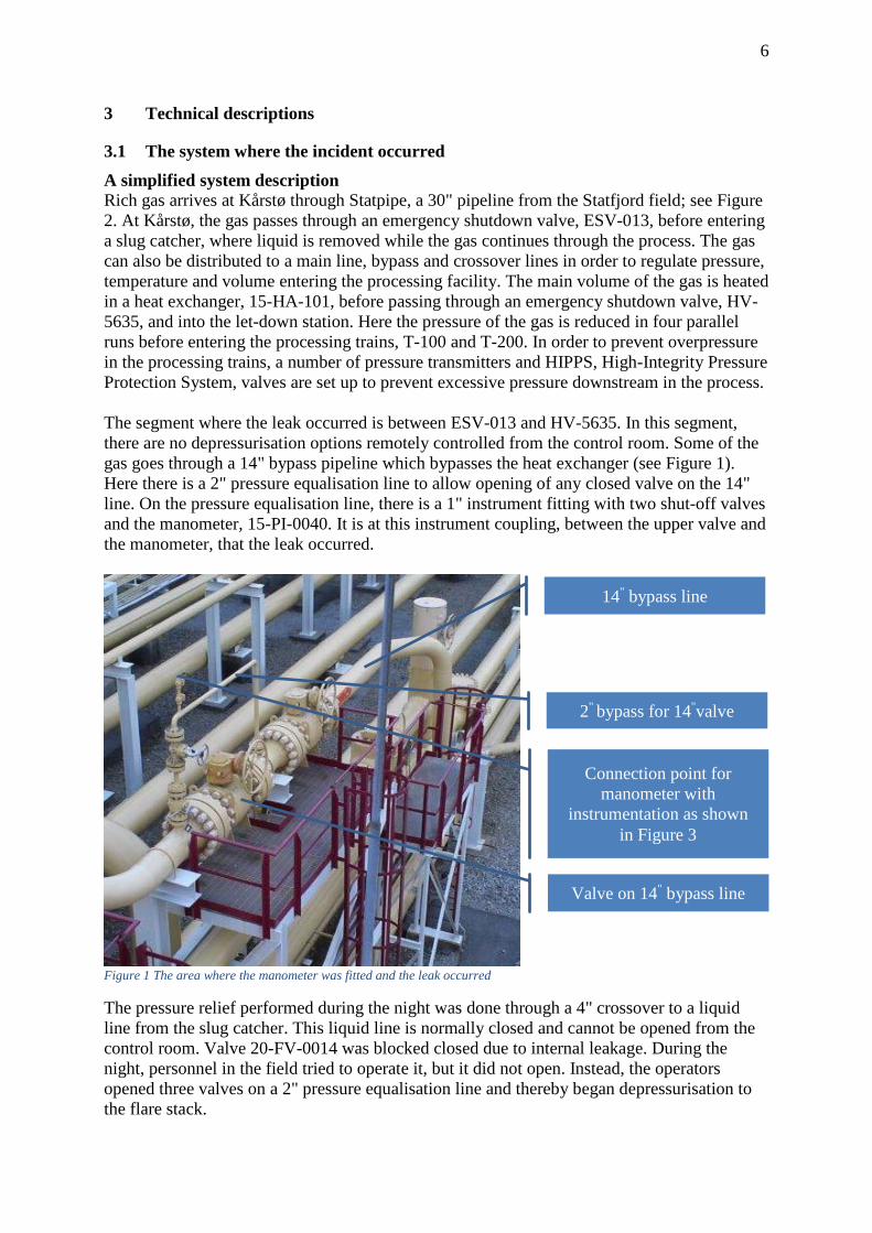
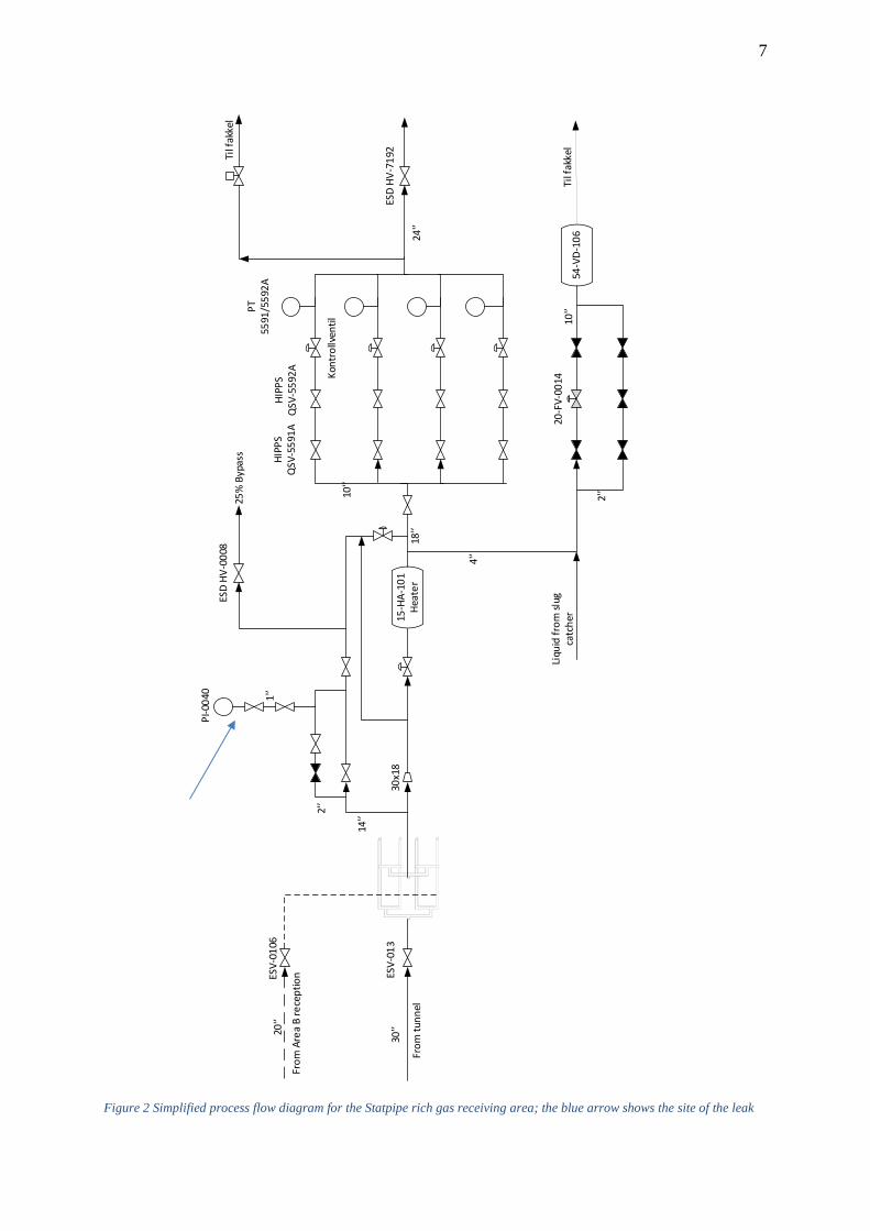
3.1 The system where the incident occurred A simplified system description Rich gas arrives at Kårstø through Statpipe, a 30" pipeline from the Statfjord field; see Figure 2. At Kårstø, the gas passes through an emergency shutdown valve, ESV-013, before entering a slug catcher, where liquid is removed while the gas continues through the process. The gas can also be distributed to a main line, bypass and crossover lines in order to regulate pressure, temperature and volume entering the processing facility. The main volume of the gas is heated in a heat exchanger, 15-HA-101, before passing through an emergency shutdown valve, HV-5635, and into the let-down station. Here the pressure of the gas is reduced in four parallel runs before entering the processing trains, T-100 and T-200. In order to prevent overpressure in the processing trains, a number of pressure transmitters and HIPPS, High-Integrity Pressure Protection System, valves are set up to prevent excessive pressure downstream in the process. The segment where the leak occurred is between ESV-013 and HV-5635. In this segment, there are no depressurisation options remotely controlled from the control room. Some of the gas goes through a 14" bypass pipeline which bypasses the heat exchanger (see Figure 1). Here there is a 2" pressure equalisation line to allow opening of any closed valve on the 14" line. On the pressure equalisation line, there is a 1" instrument fitting with two shut-off valves and the manometer, 15-PI-0040. It is at this instrument coupling, between the upper valve and the manometer, that the leak occurred.
Figure 1 The area where the manometer was fitted and the leak occurred
The pressure relief performed during the night was done through a 4" crossover to a liquid line from the slug catcher. This liquid line is normally closed and cannot be opened from the control room. Valve 20-FV-0014 was blocked closed due to internal leakage. During the night, personnel in the field tried to operate it, but it did not open. Instead, the operators opened three valves on a 2" pressure equalisation line and thereby began depressurisation to the flare stack.
14" bypass line
Valve on 14" bypass line
2" bypass for 14"valve
Connection point for manometer with
instrumentation as shown in Figure 3
7
From
Are
a B
rece
ptio
nESV-
0106
From
tunn
el
ESV-
013
PI-0
040 1'’
2'’
14'’
15-H
A-10
1He
ater
18'’
4'’
2'’
10'’
54-V
D-10
6Ti
l fak
kel
ESD
HV-7
192
ESD
HV-0
008
25%
Byp
ass
Til f
akke
l
24'’
HIPP
SQ
SV-5
591A
HIPP
SQ
SV-5
592A Ko
ntro
llven
til
PT55
91/5
592A
20-F
V-00
14Li
quid
from
slug
ca
tche
r
30x1
8
20'’
30'’
10'’
Figure 2 Simplified process flow diagram for the Statpipe rich gas receiving area; the blue arrow shows the site of the leak

8
3.2 Description of the equipment involved in the incident The manometer with associated instrumentation is shown in Figure 3. The composition and technical data are presented in an annexed damage investigation report prepared by DNV-GL on behalf of the PSA.
Figure 3 Manometer with associated instrumentation
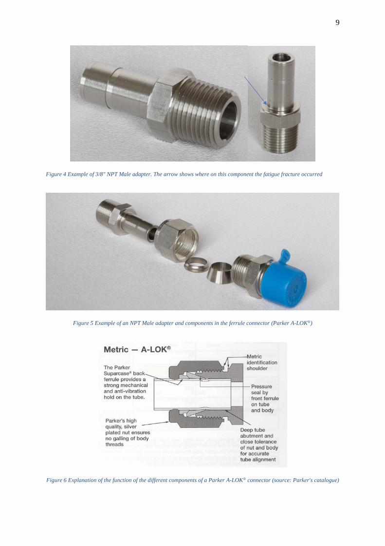
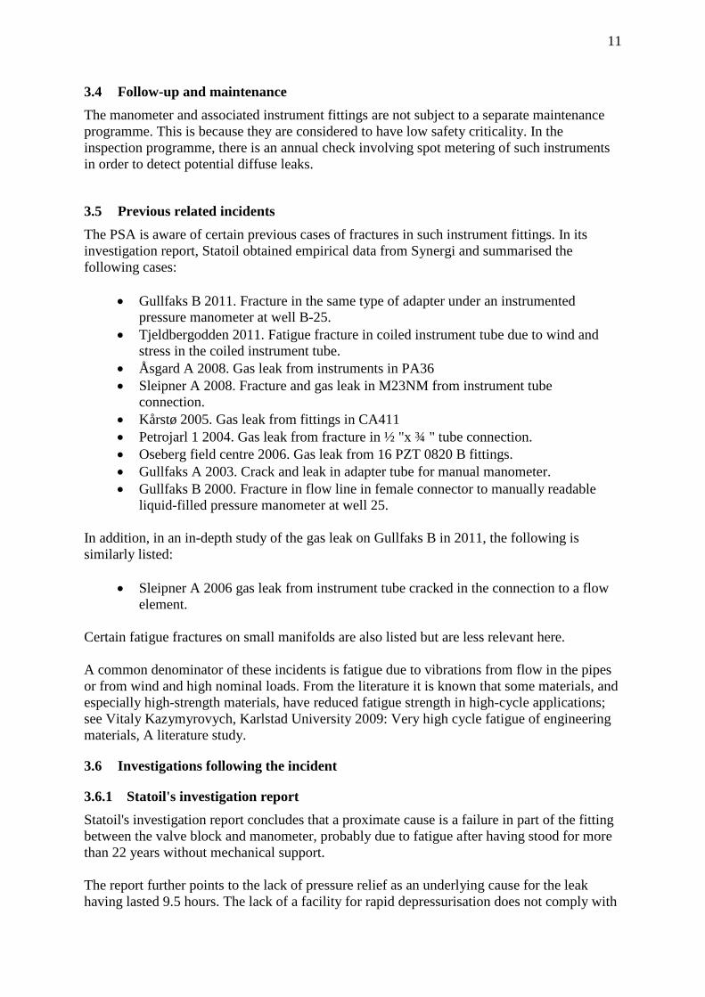
The component where the breach occurred is designated in Parker's catalogue as an NPT Male Adapter for metric tube. The photos in Figure 4 show such a component. The arrow shows where on the component the fatigue fracture occurred. The manometer dial has a diameter of 16.1 cm following its replacement in 2007. The fracture occurred in the 1/2" NPT male adapter which is the weakest part of the installed instrument fitting. It is screwed into the valve block below the manometer. The NPT Male adapter also goes into a twin ferrule connection of type Parker A-LOK® as shown in Figure 5.
9
Figure 4 Example of 3/8" NPT Male adapter. The arrow shows where on this component the fatigue fracture occurred
Figure 5 Example of an NPT Male adapter and components in the ferrule connector (Parker A-LOK®)
Figure 6 Explanation of the function of the different components of a Parker A-LOK® connector (source: Parker's catalogue)

10
3.3 Design and bracing of manometer The manometer in question was fitted without mechanical support. It was positioned on the top of a 2" bypass pipe after two manual 1" shut-off valves. The height above the ground is approx. 7-8 m to the top of the 2" bypass pipe. The vertical manometer protrusion adds another approx. 70-80 cm. The entire system may be exposed to wind loads. In the valve block below the dial, there are holes for mechanical attachment which were not used. An absence of attachment may have led to major vibrations in the system. The positioning and size of the dial were chosen to facilitate reading by operating personnel from ground level or from an adjacent module to the west. There is no nearby structure that permits simple support or attachment of the manometer. Photos of the positioning of the manometer appear as Figure 7 and Figure 8.
Figure 7 Photo of the manometer on top of a 2" bypass line seen from the east
Figure 8 Photo showing the positioning of the manometer on top of a 2" bypass line seen from the south
11
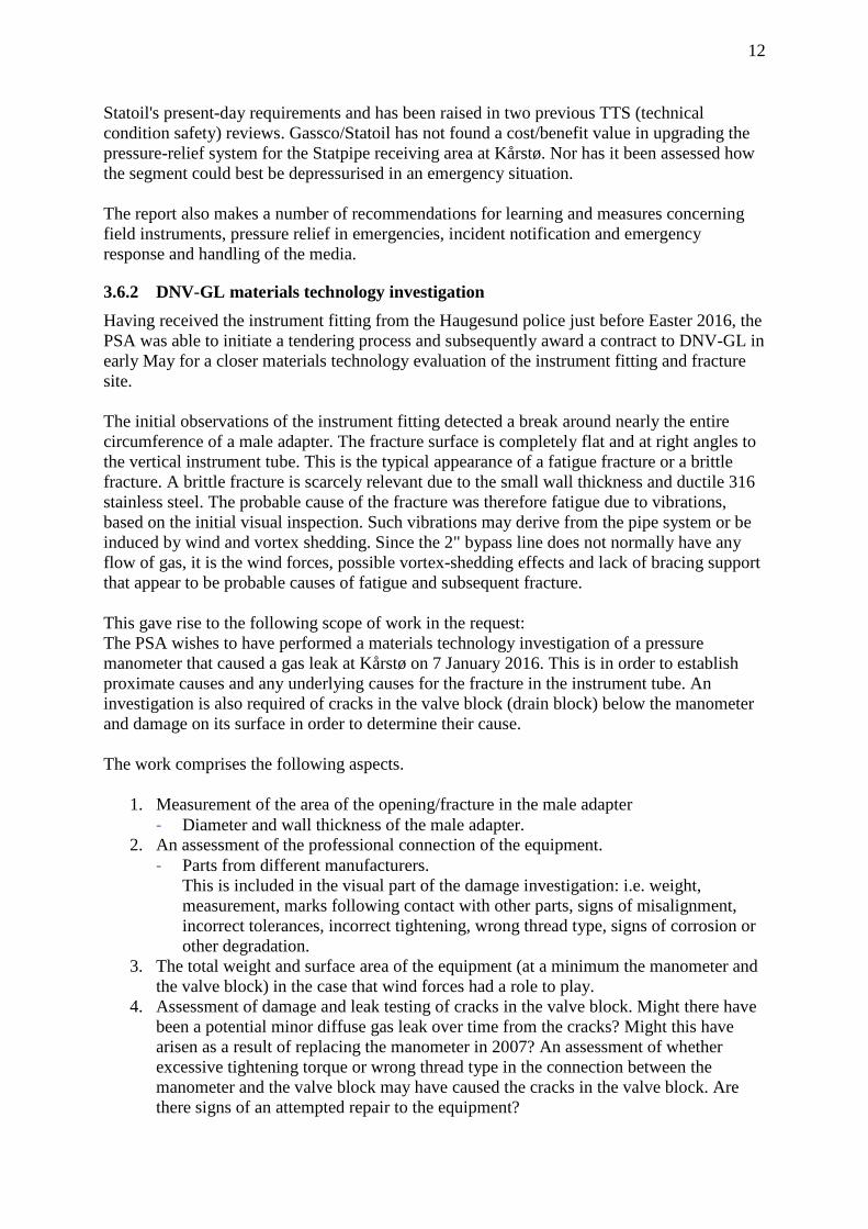
3.4 Follow-up and maintenance The manometer and associated instrument fittings are not subject to a separate maintenance programme. This is because they are considered to have low safety criticality. In the inspection programme, there is an annual check involving spot metering of such instruments in order to detect potential diffuse leaks.
3.5 Previous related incidents The PSA is aware of certain previous cases of fractures in such instrument fittings. In its investigation report, Statoil obtained empirical data from Synergi and summarised the following cases:
• Gullfaks B 2011. Fracture in the same type of adapter under an instrumented pressure manometer at well B-25.
• Tjeldbergodden 2011. Fatigue fracture in coiled instrument tube due to wind and stress in the coiled instrument tube.
• Åsgard A 2008. Gas leak from instruments in PA36 • Sleipner A 2008. Fracture and gas leak in M23NM from instrument tube
connection. • Kårstø 2005. Gas leak from fittings in CA411 • Petrojarl 1 2004. Gas leak from fracture in ½ "x ¾ " tube connection. • Oseberg field centre 2006. Gas leak from 16 PZT 0820 B fittings. • Gullfaks A 2003. Crack and leak in adapter tube for manual manometer. • Gullfaks B 2000. Fracture in flow line in female connector to manually readable
liquid-filled pressure manometer at well 25. In addition, in an in-depth study of the gas leak on Gullfaks B in 2011, the following is similarly listed:
• Sleipner A 2006 gas leak from instrument tube cracked in the connection to a flow element.
Certain fatigue fractures on small manifolds are also listed but are less relevant here. A common denominator of these incidents is fatigue due to vibrations from flow in the pipes or from wind and high nominal loads. From the literature it is known that some materials, and especially high-strength materials, have reduced fatigue strength in high-cycle applications; see Vitaly Kazymyrovych, Karlstad University 2009: Very high cycle fatigue of engineering materials, A literature study.
3.6 Investigations following the incident
3.6.1 Statoil's investigation report Statoil's investigation report concludes that a proximate cause is a failure in part of the fitting between the valve block and manometer, probably due to fatigue after having stood for more than 22 years without mechanical support. The report further points to the lack of pressure relief as an underlying cause for the leak having lasted 9.5 hours. The lack of a facility for rapid depressurisation does not comply with
12
Statoil's present-day requirements and has been raised in two previous TTS (technical condition safety) reviews. Gassco/Statoil has not found a cost/benefit value in upgrading the pressure-relief system for the Statpipe receiving area at Kårstø. Nor has it been assessed how the segment could best be depressurised in an emergency situation. The report also makes a number of recommendations for learning and measures concerning field instruments, pressure relief in emergencies, incident notification and emergency response and handling of the media.
3.6.2 DNV-GL materials technology investigation Having received the instrument fitting from the Haugesund police just before Easter 2016, the PSA was able to initiate a tendering process and subsequently award a contract to DNV-GL in early May for a closer materials technology evaluation of the instrument fitting and fracture site. The initial observations of the instrument fitting detected a break around nearly the entire circumference of a male adapter. The fracture surface is completely flat and at right angles to the vertical instrument tube. This is the typical appearance of a fatigue fracture or a brittle fracture. A brittle fracture is scarcely relevant due to the small wall thickness and ductile 316 stainless steel. The probable cause of the fracture was therefore fatigue due to vibrations, based on the initial visual inspection. Such vibrations may derive from the pipe system or be induced by wind and vortex shedding. Since the 2" bypass line does not normally have any flow of gas, it is the wind forces, possible vortex-shedding effects and lack of bracing support that appear to be probable causes of fatigue and subsequent fracture. This gave rise to the following scope of work in the request: The PSA wishes to have performed a materials technology investigation of a pressure manometer that caused a gas leak at Kårstø on 7 January 2016. This is in order to establish proximate causes and any underlying causes for the fracture in the instrument tube. An investigation is also required of cracks in the valve block (drain block) below the manometer and damage on its surface in order to determine their cause. The work comprises the following aspects.
1. Measurement of the area of the opening/fracture in the male adapter - Diameter and wall thickness of the male adapter.
2. An assessment of the professional connection of the equipment. - Parts from different manufacturers.
This is included in the visual part of the damage investigation: i.e. weight, measurement, marks following contact with other parts, signs of misalignment, incorrect tolerances, incorrect tightening, wrong thread type, signs of corrosion or other degradation.
3. The total weight and surface area of the equipment (at a minimum the manometer and the valve block) in the case that wind forces had a role to play.
4. Assessment of damage and leak testing of cracks in the valve block. Might there have been a potential minor diffuse gas leak over time from the cracks? Might this have arisen as a result of replacing the manometer in 2007? An assessment of whether excessive tightening torque or wrong thread type in the connection between the manometer and the valve block may have caused the cracks in the valve block. Are there signs of an attempted repair to the equipment?

13
Are there signs of damage to the equipment that might indicate that the equipment itself has been impacted by other equipment/objects during its lifetime? An investigation/evaluation is also requested of scratches and damage to the valve block together with frayed thread tape in the fittings. Are their signs that the equipment has been screwed on or damaged after installation in 1993/1994 and replacement of the manometer in 2007?
5. Fractographic analysis under stereo microscope and scanning electron microscope (SEM) of fracture surfaces in the instrument fitting and cracks in the valve block.
6. Metallographic examination of microstructures in the instrument fitting close to the fracture site and of the valve block and cracks therein.
7. Identification of material quality using PMI (positive material identification) or using SEM and hardness measurements. - If the fracture in the instrument fitting proves to be fatigue, a closer
investigation/mapping of the fatigue progress and initiation site is requested by SEM (possible enclosures in the material using chemical analysis in an SEM, or external damage with possible stress concentrations?). The intention of this is to determine direction of propagation, progress over time and duration of the fatigue, as well as the size of fatigue stresses and the extent of residual tensile strength.
8. If the fracture analysis of the male adapter shows that the fracture was initiated by a large external mechanical force/twist, an opinion should be given on whether this can be related to external damage and cracks in the valve block.
The scope of work was extended after 14 days with an analysis and data model to calculate the effect of static wind loads and dynamic wind loads as a result of vortex shedding. The somewhat simplified data model included both the 2" bypass tube and the instrument fitting/manometer. The purpose of this extension was to provide a more comprehensive analysis of the causal relationships between observed fatigue damage, the system's natural frequencies and potential wind loads. This comprised:
• Modelling of the entire bypass loop including weight and length, location of valves and valve block/manometer.
• Reading of the natural frequencies of the valve block/manometer through different vibration modes (including animations).
• Modelling of the effect of supposed supporting of the valve block. • Assessment of wind loads, including both static and dynamic wind loads. • Reporting of results.
3.6.3 Summary of the DNV-GL report The investigation covered the valve block, the instrument fitting and its fracture, and the manometer. The instrument fitting, which was part of a so-called ferrule connection (male adapter and twin ferrule), was observed to have a bilateral fatigue fracture. This occurred on the male adapter in the angular transition between the tube and the hex flats. This area represents the smallest cross-section in the assembly and is accordingly a weak point. The transition is relatively sharp and constitutes a considerable stress concentration. The fatigue fracture occurred in the most stressed area of the assembly.

14
FE modelling and calculations were made of the 2" bypass loop in question with an analysis of the system's natural frequencies. Calculations were also made of wind loads and vortex-shedding frequencies. The results show that the system's natural frequencies coincide with potential vortex-shedding frequencies for winds between 5 and 25 m/s. A likely cause of the fracture which led to the gas leak is considered to be bending fatigue as a result of the system's natural frequencies coinciding with vortex-shedding frequencies at normal wind speeds. Indirect causes are a lack of support of the assembly and use of a thin-walled instrument fitting as a load-bearing element. Due to a lack of historical information on how and how much the 2" bypass system has been used for pressure equalisation since installation, it has not been possible to assess whether flow-induced loads could have been a contributory cause of the fatigue damage. The valve block had an external crack-like defect that was suspected of being a possible secondary leak. The valve block was pressure-tested in DNV-GL's test laboratory up to 135 bar using water. No sign of a leak was detected. The fault was assessed to be superficial and probably related to manufacturing. For a full report, see Annex B.
3.6.4 The Petroleum Safety Authority Norway's assessments of findings in the DNV-GL report
The technical materials investigation has no major uncertainties in terms of establishing the proximate cause of the leak. A large, sudden external load can be excluded as a cause of the fracture and gas leak. The fracture and gas leak are due to a crack which propagated due to varying bending stresses, causing fatigue. There was a contribution to higher bending stresses due to the entire system falling within the natural frequency range for vortex shedding at normal wind speeds at Kårstø. No clear failure of the material's properties or surface was identified. A few instances of microscopic pitting corrosion were seen close to the initiation site. The transition between the turned male adaptor tube and the hex flats has a small radius. This will add an extra stress concentration factor at the initiation site. In addition, it is here that there is the thinnest wall thickness in the instrument fitting and hence the greatest nominal stresses. The instrument fitting and male adapter satisfy all requirements in relevant standards at the time they were supplied and assembled. The coupling is certified for a pressure of up to 400 bar. In 1995, the supply standard for this type of male adapter was altered to a somewhat greater wall thickness and certified for 690 bar.
4 Sequence of events The description of the sequence of events is based on conversations with and interviews of personnel at Kårstø and a review of documentation.
4.1 Incidents prior to 7 January 2016 1993/1994 Part of the plant (rich gas bypass) where the leak occurred was built and put into
operation. The original manometer was of type 3PXF160 1/2" from Clausen, Kaldager & Co A/S. The manometer was registered in the maintenance system on 9 November 1993.

15
22 August 2006 Notification (40565546) written for manometer 15-PI-0040 in connection
with the performance of an inspection. Mechanical damage, corrosion and wear are reported, and that the manometer is working poorly but is functional. Deadline for rectification set at 17 August 2007 (<12 months). The consequence classification of the equipment is low.
21 March 2007 Manometer was replaced. The new manometer is made by Wika.
Based on the age of the fittings (produced in 1992 and 1993), everything indicates that these were not replaced and are still the original parts from when this section of the plant was built. According to Statoil's investigation report, the automation technician concerned confirmed that only the manometer was replaced and the other parts were reused.
19 March 2013 ALARP report (E002-XX-S-RE9093) recommends not installing two new pressure-relief valves linked to the Statpipe/Sleipner receiving area based on a cost/benefit analysis.
4.2 The chain of events on 7 and 8 January 2016 Times defined to the second are based on data from alarm logs. 7 January 2016 Day time Digging work in progress in area CA16. 22:00 Area operator (apprentice) passes through area CA16. Observes nothing
abnormal. Approx. 22:16 Leak occurs through a fracture in the male adaptor for manometer 15-PI-
0040. 22:16:28 First indication that the leak has started. Gas detector 31-GD-5825R registers a
small effect. It is so small that it does not trigger an alarm in the control room. 22:16:45 First gas detector (31-GD-5824R) triggers a "high alert" in the control room. Approx. 22:16 Operator D2 (mobile operator) is notified by radio of the gas leak indication
and is asked to check and report. 22:17:12 A second gas detector (31-GD-5825R) triggers a "high alert" in the control room.
Both detectors are in the same fire area (2R123). Approx. 22:17 Operator D2 reports back that he can both see and hear the leak from his
position at the north-east corner of the main control room building. 22.17.32 Detector 31-GD-5825R issues a high-high alarm. The combination of one detector
at high-high and at least one at high triggers a confirmed gas detection in the fire and gas system.
22:17:33 Automatic ignition source decoupling is initiated for Statpipe and Sleipner.

16
22:17 Gas alarm - blue light activated. 22:18 1st-line emergency response established in MCR (Main Control Room). 22.18.11 Detector 15-GD-5586 issues a high-high alarm. 22.18.23 Detector 15-GD-5587 issues a high-high alarm. 22.19.36 Detector 15-GD-5594R triggers a "high alert". 22:20 Plant alarm Approx. 22:20 Operations Manager East receives go-ahead from shift supervisor to cycle
from Operations Building East (OBE) to MCR via the southern route. During the cycle ride, he hears the plant alarm go off.
22.20.33 Detector 15-GD-5588 issues a high-high alarm. 22:25 MCR notifies
- Forus Alarm Centre - Neighbouring businesses - Gassco - The Police - The Fire Service - Helse Fonna/ambulance
22.26.19 Detector 31-GD-5812 issues a high-high alarm. 22:27:14 Emergency shutdown (15-ES-0004) for the Statpipe rich gas inlet was
implemented manually from a CAP panel in the control room by a Statpipe panel operator.
22:27:16 The emergency shutdown valves for the Statpipe rich gas inlet receive a shutdown
signal. Approx. 22:27 The Statpipe panel operator confers with the shift supervisor concerning
emergency shutdown of T-100 and T-200. This measure was not implemented. It was decided to perform a controlled shutdown of T-100 and T-200.
22:27:36 Pressure sensor for HIPPS valves issues an HH alarm 22.27:39 HIPPS valves close 22:27:51 Emergency shutdown valve 15HV5635 is closed. 22:28:17 Emergency shutdown valve 31ESV013 for the Statpipe inlet is closed. 22:28:19 Depressurisation is initiated manually by the Statpipe panel operator for part of
the processing plant downstream of the Statpipe inlet (blowdown fire area

17
2R123). The Statpipe inlet itself can now only be depressurised through manual valves in the field.
22:40 The PSA's emergency response officer has received notification from Gassco. 22:40 Warning to neighbours sent by SMS (time from incident log) 22:47 Noted in incident log that operational personnel must stay indoors and that there is
still a leak Approx. 22:50 MCR understands that the 2nd line has not been mobilised (has not received summons). MCR summons the 2nd line. 23:00 Sleipner boiler tripped Approx. 23:05 2nd-line emergency response established. 23:12 5 gas detectors active, large leak still ongoing. The active detectors are 15-
GD5586, 15-GD5587, 15-GD5588, 31-GD5824 and 31-GD5825R. 23:15 Kristin compressor tripped 23:23 Pressure at CA16 slowly falls. Blue light still on. 23:45 Large leak continues at CA16. 23:45 Full check of personnel 23:45 Second line set to help. It is attempted to find alternatives to stop the leak from the
confined segment without sending out personnel to operate manual valves. 8 January 2016 03:00:51 Opened 15-HV5635. This does not produce the desired effect since the HIPPS
valves downstream are closed and cannot be opened without manual resetting in the field.
04:07 2 operators are sent out to the area by T-200 in order to open 4" valve 20-FV-0014
to flare drum 54-VD-106. Depressurisation cannot be achieved by this valve and it is decided instead to try to open the valve's 2" bypass line.
04.20 Personnel succeed in opening the valve's 2" bypass line. This provides pressure
relief to the flare stack through a line for draining liquid to the flare drum. At this time, the pressure has fallen from approx. 140 bar to 86 bar.
07:14 The pressure has fallen to below 10 bar and personnel reset HIPPS valves in the
field. This provides further, more rapid pressure relief.
18
07:50 Two block valves below the manometer are closed by personnel and the leak is stopped. The manometer and associated fittings are disassembled and a blind plug is inserted where the manometer was installed.
5 The potential of the incident
5.1 Actual consequences Actual consequences were a gas leak with an estimated initial rate of 1.3 kg/s and a duration of 9.5 hours. The estimated volume of hydrocarbons released to the air is 22 metric tonnes. The Statpipe facility was closed down for more than half a day with consequent loss of production. No exposure or harm to personnel. Little material damage and limited environmental harm.
5.2 Potential consequences The cause of the gas leak is determined to have been material fatigue. The time of the fatigue fracture is consequently arbitrary. Around 15 minutes before the leak, there was an operator in the area on a logging round. During the day time, there was digging work in the area with a work team of several persons and machinery that could potentially have been an ignition source.
5.2.1 Potential consequences without ignition The size of the gas cloud suggests that personnel in the immediate neighbourhood could have been exposed to gas. Exposure to gas can produce a narcotic effect and cause suffocation.
5.2.2 Potential consequences in the case of ignition According to the gas-hazard analysis that Statoil performed in follow-up to the incident, a fire/explosion could have caused serious personal injury if there had been personnel present within or near the combustion zone at the time of ignition. Fatalities would not be excluded. The gas-hazard analysis also assessed that flare pipe VF-54-4631 and gas pipe PG-15-3006 could have been exposed to heat loads on ignition that could have led to pipe ruptures. PG-15-3006 is a pipe which links the liquid separation section of the Statpipe slug catcher with the receiving plant for Åsgard processing. This pipe was pressurised to 140 bar during the entire incident, i.e. it was not depressurised. The pipe has no passive fire protection. This could have caused the incident to escalate.
6 Observations The PSA's observations generally fall into three categories. • Non-conformity: In this category are observations where the PSA believes the regulations
have been breached. • Improvement point: Concerns observations where we see deficiencies, but do not have
sufficient information to be able to identify a breach of the regulations. • Compliance/barriers that worked: Used in the case of demonstrated compliance with the
regulations.

19
6.1 Non-conformity
6.1.1 Mechanical support of instrument Non-conformity The manometer was fitted without mechanical support. Rationale In an area exposed to the weather, 7-8 m above ground level, a manual manometer is installed on top of a 2" bypass pipe, first by a 1" tube with two manual shut-off valves approx. 40 cm in length, and then a 6.5 cm long piece with ½" instrument fittings as a spacer before the valve block and manometer. There are holes in the valve block for mechanical support, but these were not used. Attachment of such equipment must be considered normal practice in order to meet the requirements for robust design without this being specifically described in standards or the company's policies. Requirements The Management Regulations, Section 4 concerning risk reduction, 1st para.
6.1.2 Learning and improvement Non-conformity Statoil has not ensured adequate learning and improvement following a number of similar recorded incidents. Rationale Chapter 3.5 describes a number of incidents that could provide a foundation for learning and assessing the integrity of similar equipment across the company. A common denominator of these incidents is fatigue due to vibrations from flow in the pipes or from wind and high nominal loads. Requirements The Management Regulations, Section 23 concerning continuous improvement
6.1.3 Lack of a plan for depressurisation in an emergency situation Non-conformity No plan had been prepared for pressure relief in an emergency situation in areas without remotely-operated depressurisation options. Rationale During the leak, operational personnel in the control room reviewed the P&IDs in order to find depressurisation options with support from the stand-by operations engineer and the incoming shift in Operations Building East. This work was time-consuming. It also resulted in a number of alternative depressurisation attempts before a working solution was found. This could have been avoided if a plan had been prepared beforehand. Requirements The Management Regulations, Section 5 concerning barriers, last para.

20
6.2 Improvement point
6.2.1 Assessment of manometer with associated instrument fittings Improvement point Lack of assessment of the design and assembly of the manometer and associated instrument fittings in connection with its replacement in 2007. Weaknesses in the system were not detected through follow-up in operation. Rationale The use of a male adapter with a sharp angular transition entails a high stress-concentration factor and bending loads in its weakest part (male adapter). Structural weaknesses in respect of fatigue loads do not appear to be a risk that was assessed when replacing the equipment. We are not aware that any assessment was made when the manometer dial was replaced in 2007. A general annual review of this type of equipment has been established with spot metering for leaks in order to confirm the integrity of the system. This would not be sufficient for detecting possible weaknesses in the system. Requirements Technical and Operational Regulations, Section 57 concerning monitoring and control, first para. The Management Regulations, Section 4 concerning risk reduction, first para.
21
6.2.2 Notification/summoning of 2nd-line emergency response organisation at Kårstø Improvement point The 2nd-line emergency response organisation at Kårstø was not notified and summoned as described in governing documents. Rationale During the interviews, it emerged that Statoil's Forus Alarm Centre had not notified/summoned the 2nd-line emergency response team at Kårstø. When the 1st-line emergency response team realised this (at approx. 22:50), the 1st line summoned the 2nd-line emergency response organisation themselves. The 2nd-line emergency response team was established at around 23:05, which is within established time parameters. Statoil's Forus Alarm Centre was notified at around 22:20, meaning the the notification/summoning of the 2nd-line emergency response organisation at Kårstø was delayed by around half an hour. During the interviews, it also emerged that the responsibility for notifying/summoning the 2nd-line emergency response organisation was transferred in the autumn of 2015 from the 1st-line to Statoil's Forus Alarm Centre. Requirements Technical and Operational Regulations, Section 67 concerning handling hazard and accident situations, letter a)
6.2.3 Fault in P&IDs Improvement point P&IDs were incorrectly marked. Rationale On P&ID D003-XX-F38-PE0604.002 and P&ID E002-XX-15-PE0100.001, a closed spade and spacer is marked on the pipe with line number PG-15-0021. Through discussions, it emerged that these should have been marked open on the drawings. Requirements The Management Regulations, Section 15, concerning information
6.3 Barriers that did function: Despite the non-conformities and improvement points presented in chaps 6.1 and 6.2, we note that the situation was normalised without further escalation. The Statpipe processing section of the plant was constructed at a time when different safety philosophies for the handling of emergency situations prevailed. When the plant was constructed, in a similar case, an operator would have been sent out to operate the safety valves and thereby segment the depressurisation. The current safety philosophy at Kårstø is that all personnel must keep away from gas leaks, and such an opportunity for depressurising certain segments is lost. When a leak first occurs, the consequence is that it will leak through the leak point until the plant is depressurised. Accordingly, it is highly important that barriers for preventing escalation function as intended. We have not carried out a thorough mapping and analysis of all barriers that did function, but point to some barriers that worked as intended.
• Gas detection. The leak was detected and automatic systems for preventing escalation were initiated as planned.

22
• Ignition source decoupling. On confirmation of gas, ignition sources in the area were disconnected from power, which reduced the likelihood of possible ignition and explosion/fire.
• Establishment of the emergency response organisation. Statoil Kårstø established the emergency response organisation in accordance with defined efficiency requirements. This is despite the fact that notification and summoning of the 2nd-line emergency response organisation was unnecessarily delayed by around half an hour; see improvement point 6.2.2 above. Notification of Gassco and external resources (police, fire, health service/ambulance) was carried out in accordance with plans.
7 Other comments Lack of depressurisation options It is not possible to depressurise the Statpipe inlet from the control room. In accordance with the design and original regulations, there are only manual depressurisation options in the field. The lack of depressurisation options was identified as a non-conformity under present requirements in TTS (technical condition safety) reviews in both 2004 and 2007. Measures have been ALARP-assessed in connection with the KIP upgrade project, but, based on a cost-benefit analysis, it is not planned to implement these measures. Time to initiate ESD Nearly 10 minutes passed from confirmed gas detection to initiation of ESD. At 22:17:32, there was a confirmed gas leak in the plant. ESD was activated at 22:27:14. The gas leak was located early on, by CCTV in the control room, gas detectors and a mobile operator. It is unclear why it took so long for ESD to be initiated. The latest total risk analysis for Kårstø, E002-XX-S-RS9135, assumes 300 seconds to shutdown for a medium-sized leak. Choice of ESD level At 22:27, ESD level 4, 15-ES-0004, was pressed on the local CAP. This closes the Statpipe inlet. At both the main CAP and local CAP, there are instructions affixed from 2011, saying that ESD level 3 must be pressed in the case of a leak in the Statpipe inlet. ESD 4 does not perform an emergency shutdown of the Statpipe downstream processing trains. These were shut down manually instead, after the feed into the trains had been stopped. It was explained to us that this was done to protect the equipment. Addendum to: TR2237 Performance standards for safety system and barriers – onshore, chap. 4.2.11. FA 3R123, Statpipe/Sleipner receiving area, states the following: It shall be evaluated what level of ESD to initiate; in a leakage scenario where the source is known, ESD level 4 for the affected system only (15-ES-0004 Statpipe, 36-ES-3002 Sleipner) may be chosen. The Statpipe ESD-group also include the inlet valves to the processing trains T100/200, meaning the trains lose the feed and will have to shut down. For Sleipner the situation is similar, closure of the pipeline inlet valve will cause the processing train T300 to shut down due to lack of feed. With this in mind, if Statpipe inlet is to be shut down, ESD level 3 (15-ES-0003) should be initiated directly to avoid any cascading effects. The situation is the same for Sleipner, ESD for T300/DPCU/refrigeration (20-ES-3001) should be initiated directly in addition to the inlet if the inlet has to be closed. False alarms due to steam and "noise"

23
In the review of the incident log, it emerged that there were also detections in areas that, under the prevailing wind conditions, were not within the area affected by the leak. These were explained as being a known problem caused by emissions of steam. We are not aware that measures have been assessed for avoiding conditions where false detections are known to occur.
8 Discussion concerning uncertainties
8.1 Potential consequences There is uncertainty concerning the assessment of potential consequences of the incident. The PSA's investigation group took as its basis information obtained from the gas-hazard analysis, Statoil's own investigation report and information acquired through discussions during the investigation at Kårstø.
8.2 Uncertainty in materials technology investigations The technical materials investigation has no major uncertainties in terms of establishing the proximate cause of the leak. A large, sudden external load can be completely excluded as a cause of the fracture and gas leak. The fracture and gas leak are due to a crack which propagated due to varying bending stresses, causing fatigue. It is normally said that 90% of fatigue life relates to initiation and approx. 10% to fracture propagation. Furthermore, a fatigue crack is likely to become a through crack when the crack at the surface is twice the wall thickness of the tube. The materials investigation shows many small fatigue striations after the crack had probably penetrated the tube wall. There may therefore have been a smaller, diffuse leak from this through crack for a while before the actual full fracture. The materials technology investigation does not provide answers for the likely duration of a diffuse leak of this kind. This would have required detailed knowledge of stress states and a very thorough SEM mapping, which was impossible due to the degradation, oxidation and contamination of parts of the fracture surfaces. In addition, the circumstances would have been shrouded in great uncertainty.
8.3 Interior gas-flow technical assessments It cannot be completely excluded that gas-flow-induced loads caused vibrations in the 2" bypass pipe. But normally, there is no flow in this pipe other than when pressure-equalising in order to open valves in the 14" pipe which the 2" bypass pipe bypasses. And in the other large pipes, there have been stable conditions over time with the flow of dry gas at a reasonably low gas velocity. The PSA therefore has no reason to assume that the propagation and fracturing are due to flow conditions.
9 The following documents were used as a basis for the investigation: - Statoil's investigation report of the incident: "Gasslekkasje i Statpipe mottaksområde
på Kårstø" (Gas leak in the Statpipe receiving area at Kårstø), Report no. A 2016-1 MMP L2, dated 10 March 2016
- "Gassfareanalyse, Gasslekkasje på Kårstø 7. januar 2016" (Gas hazard analysis, Gas leak at Kårstø on 7 January 2016), Synergi 1461681, published on 10 March 2016
- Statoil's in-depth study of the Gullfaks B incident on 7 November 2011 "Gasslekkasje i instrumentkobling på brønn B-25 strømningslinje" (Gas leak in instrument coupling at well B-25 flow-line), Synergi no. 1264920, dated 20 December 2011

24
- Statoil's in-depth study following the incident at Tjeldbergodden in 2011 with a fatigue fracture in a coiled instrument tube due to wind and stress in the coiled instrument tube. RUH 1215333.
- Parker product catalogue "Fittings, Materials and Tubing Guide, Instrumentation Products"
- P&IDs for Statpipe rich gas inlet - Alarm logs for 7 and 8 January 2016 - Emergency response logs from the incident - Maintenance history from SAP for manometer 15-PI-0040
10 Annexes Annex A: List of participants from parties concerned. Annex B: DNV-GL technical report, case no. 2016/45, "Skadeunderøkelse av instrumentfitting, Kårstø" (Damage investigation of instrument fitting, Kårstø), Report no. 2016-3074, Rev. 0, 27 May 2016