
Investigation report - ptil.no på nettet/Granskinger/gfb...In connection with leak testing after...
52
Investigation report Report Report title Activity number Gas leak on Gullfaks B 4 December 2010 001050014 Security grading Public Not publicly available Restricted Confidential Strictly confidential Summary The gas leak occurred during leak testing after maintenance work on a production well. The gas derived from a volume trapped between the downhole safety valve and the Xmas tree. It proved impossible to operate the emergency shutdown valves on the well. The leak lasted about an hour, with an initial rate of 1.3 kilograms of gas per second. The volume of gas released is estimated at about 800 kilograms. No people were injured in the incident, but the leak created a serious position on the installation. Involved Main group Approved by/date T1-Statoil Hanne Etterlid, coordinator supervisory activities 17 March 2011 Members of the investigation team Investigation leader Eivind Sande, process integrity Geir Erik Frafjord, process integrity Øyvind Lauridsen, organisational safety
Transcript of Investigation report - ptil.no på nettet/Granskinger/gfb...In connection with leak testing after...

Investigation report
Report
Report title Activity number
Gas leak on Gullfaks B 4 December 2010 001050014
Security grading
Public
Not publicly available
Restricted
Confidential
Strictly confidential
Summary
The gas leak occurred during leak testing after maintenance work on a production well. The gas derived from a volume trapped between the downhole safety valve and the Xmas tree. It proved impossible to operate the emergency shutdown valves on the well. The leak lasted about an hour, with an initial rate of 1.3 kilograms of gas per second. The volume of gas released is estimated at about 800 kilograms.
No people were injured in the incident, but the leak created a serious position on the installation.
Involved
Main group Approved by/date
T1-Statoil Hanne Etterlid, coordinator supervisory activities
17 March 2011
Members of the investigation team Investigation leader
Eivind Sande, process integrity
Geir Erik Frafjord, process integrity
Øyvind Lauridsen, organisational safety

2
Summary
In connection with leak testing after maintenance work on the choke valve for a production
well, a gas leak occurred on 4 December 2010 on Statoil’s Gullfaks B (GFB) installation.
This leak caused the release of about 800 kg of gas, with an estimated initial rate from the
leak site of about 1.3 kg/s. The emergency shutdown (ESD) system on the well had been put
out of action, and the leak lasted about one hour.
Personnel in the area could have suffered serious injury or been killed had the gas ignited. The
ignition probability of the specific leak is put at about one per cent. Under only slightly
different circumstances, a significantly larger leak to the atmosphere could have occurred.
Generally speaking, the cloud size and ignition probability rise with an increasing leak rate. A
leak rate significantly larger than the one actually experienced would have meant a high
probability of a large explosive gas cloud building up in the area and thereby a risk of an
explosion with a significant major accident potential.
The installation was in normal operation ahead of the incident, and work due to be performed
on the choke valve for well B-32 represented a planned preventive maintenance activity
which involved disassembling, inspecting and resetting the valve.
Identified non-conformances relate to:
planning of the work – the isolation plan had significant deficiencies
testing of barrier valves identified in the isolation plan
planning, preparing and resetting, including leak testing
identification of risk related to pressure build-up between the downhole safety valve
(DSV) and the hydraulic master valve (HMV)
maintenance of the manual master valve (MMV)
the ESD system – can be unintentionally put out of action
ensuring sufficient capacity and expertise for planning and executing the resetting job
– roles not clarified
strategy for barriers and establishing performance requirements for barrier elements
updating of risk analyses – it has not been documented that explosion-related risk was
reduced as far as possible.
The work order issued for the choke valve on well B-32 was created as part of planned
maintenance for the installation. This is conducted regularly to identify possible wear and tear
on the choke valve and production piping.
The work permit (WP) for the hydrocarbon-bearing system was approved on 2 December
2010. It was to be executed by the day shift on 3 December. The WP was approved on
condition that an approved isolation plan was drawn up before the job started.
The isolation plan for preparing the plant was drawn up the same evening and put into effect
during the night. Work on preparing the plant failed to conform at several points with the
prescribed work process. The inspection work began on the morning of 3 December, despite a
generally high level of activity and burden on control room personnel and area technicians.
Inspection revealed that baffles in the valve were so worn that they required replacing. A new
work permit for replacing the baffles was approved on 4 December. No new assessments of
the status and content of the isolation plan were made.
The mechanics involved then replaced the baffles in the choke valve, after which the plant
was to be reset and leak tested.
The work of resetting and preparing for operation was conducted by two technicians. The one
in charge had worked as a process technician on GFB for three years and had the role of area

3
technician for this job. The other person had been on GFB for a total of 16 days after working
earlier on other installations, most recently as discipline responsible mechanical. The area
technician had participated in this type of work before, but always in the company of a more
experienced process technician who was in charge.
A diesel pump is normally used to pressurise the piping in order to conduct a high-pressure
leak test of this system. That pump was not available. The area technician was unsure how he
was to reset the system when the pump was unavailable, and raised this issue with his
discipline responsible. The latter was not able to accompany the technician to the work site,
but approved the use of injection water from another well as the pressure source. The
connection point for the injection water was not discussed with the specialist manager
No specific procedures existed for this leak testing on GFB. Views differed among process
technicians on different shifts about how to conduct a low-pressure test.
In this case, the leak test was conducted by using injection water from a neighbouring well
with the pressure choked down from 136 to 40 bar. The connection point chosen was the
bleed located in the valve cross between the hydraulic master valve (HMV) and the hydraulic
wing valve (HWV) for well B-32. Nobody reacted to the fact that the connection point lay
outside the established barrier envelope in the isolation plan.
In order to conduct the leak test with the chosen connection point, the HWV had to be opened
so that the water would reach the production piping, including the choke valve. An in-built
interlock means that an opening signal cannot be given to the HWV until one has been given
to the HMV. On the other hand, the HMV does not need to be physically opened.
In this case, however, the process technician chose to close the manual master valve (MMV)
and then open both the HMV and the HWV. One reason for this assessment could be that
some shifts use the MMV as a barrier valve for this type of job. It subsequently emerged that
the MMV had a high internal leak rate.
Hydraulic pressure was released up to the closed needle valves on the hydraulic lines used for
operation of HMV and HWV. The process technician then opened the needle valves for both
the HWV and the HMV, which resulted in these two ESD valves going from closed to open
position. Opening both the HMV and the HWV allowed gas to flow through the leaky MMV
and past the Xmas tree. That caused gas to leak from an open drainage point. The time was
about 14.00
In an attempt to stop the leak, the needle valves were closed. This meant that the HWV and
the HMV were locked in the open position because the hydraulic pressure keeping the valves
open could not be bled off from the control room or through automatic ESD. As a result, the
leak lasted about an hour. If the needle valves had not been closed, the HMV and the HMV
would have responded to the ESD signal and the leak halted within one-two minutes.
One of the two process technicians was exposed to gas before they managed to leave the area.
The general alarm sounded and all personnel mustered in accordance with alarm instructions.
All personnel on board had been accounted for by 14.19.
At 14.55, it was decided to enter M14 in order to open the needle valves for the HMV and the
HWV so that the hydraulic pressure could be bled off and these ESD valves closed. At that
point, none of the gas detectors showed readings above alarm limits.
4
1 Introduction
In connection with leak testing following maintenance work on the choke valve in a
production well, a gas leak occurred on 2 December 2010 on Statoil’s Gullfaks B (GFB)
installation. The Petroleum Safety Authority Norway (PSA) resolved on the same day to
conduct its own investigation of this incident, partly because of its apparently substantial
potential (large volumes of hydrocarbon gas over a lengthy period) and partly because of
apparent deficiencies related to planning and executing a risky work operation.
The investigation team had the following composition:
Geir Erik Frafjord principal engineer, process integrity
Eivind Sande principal engineer, process integrity
Øyvind Lauridsen investigation leader, organisational safety.
The investigation team was on GFB from 6-10 December. The area was inspected, and
interviews were conducted with personnel involved in planning and executing the work, and
in managing the emergency response. Various governing documents and print-outs of data
and other logs were also assembled. In addition, video interviews were conducted on 20
December and interviews with employees in the Gullfaks land organisation in Bergen on 21
December. A total of 21 people were interviewed in all.
Work since then includes acquiring and assessing a considerable number of documents, e-
mail communications providing supplementary information, and telephone conversations with
relevant people.
The incident has been structured on a time line which describes the individual links in the
chain of events (appended).
Mandate of the investigation team:
1) Clarify the scope and course of the incident – including operational, technical,
management and emergency preparedness aspects.
2) Describe and discuss actual and potential consequences for people, the environment
and material assets.
3) Identify and discuss direct and underlying causes from a human, technological and
organisational (HTO) perspective.
4) Assess possible similarities with earlier incidents.
5) Identify breaches of regulations and improvement points, including non-conformances
with internal company requirements, approaches and procedures.
6) Barriers which functioned – in other words, those which contributed to preventing a
hazard from developing into an accident or which reduced the consequences of an
accident.
7) Discuss and describe possible uncertainties/ambiguities.
8) Recommend further follow-up by the PSA, including possible use of reactions.
9) Inform internally in the PSA.
10) Prepare an investigation report and accompanying letter in accordance with procedure.

5
2 Course of events
This chapter contains a description of the chain of events from planning of the maintenance
work to preparing, executing and readying to reset the system, which was the phase where the
gas leak occurred. The plant was in normal operation ahead of the incident, and the work to be
done on the choke valve for well B-32 was a planned preventive maintenance activity which
involved disassembling, inspecting and resetting the choke valve.
2.1 Planning the maintenance job
The work order executed with the choke valve on well B-32 was created as part of planned
maintenance on the installation. This work is conducted regularly in order to detect possible
wear and tear on the choke valve and production piping.
An application was submitted for a level 1 work permit (WP) to execute the work order
because the work was to be done on a hydrocarbon-bearing system. The WP was approved at
the meeting to review WPs on the afternoon of 2 December. It was to be executed during the
day shift on 3 December. Approval was conditional on the production of an approved
isolation plan before the work started.
2.2 Preparing the plant
The isolation plan for preparing the plant was drawn up the same evening and implemented in
during the night. Requirements for this work process are described in OMM 05.07.01.01no –
Prepare normally pressurised system/equipment for activity requiring isolation. Work on
preparing the plant deviated on several points from the prescribed work process:
it is not documented who had the role of verifier for the isolation plan, and the plan
was not formally approved by the operational systems responsible manager before
isolation was implemented in the field
hose connections are not indicated on the P&ID
no requirement is set for leak testing of the hydraulic wing valve (HWV), which
serves as a barrier in the double block and bleed (DB&B)
the isolation plan lacks a brief introduction which describes the purpose of the work
operation
it is not stipulated that no leaks are accepted through valves incorporated in the DB&B
because the plant is to be opened to the atmosphere downstream well barriers.
The preparations were nevertheless approved by the operational systems manager in the
morning, and the WP was activated for execution.
At the meeting of 07.00 on 3 December to review the day’s level 1 WPs, it was proposed to
delay this job because of a generally high level of activity and burden on control room
personnel and area technicians. It was decided to execute the WP as planned, probably in
order to reduce the backlog of outstanding preventive maintenance.
6
2.3 Execution of the maintenance work
Work on 3 December started with the area technician and the executing mechanic checking
the preparation of the plant in the field. This was found to accord with the isolation plan, and
maintenance work began.
According to the work order, the choke valve should only have been opened downstream. The
mechanic opted to take out the whole choke. Inspection showed that baffles in the valve were
so worn that they required replacing. Combined with the full removal of the valve, this
probably contributed to the job extending over two days. Replacing baffles required
disassembly of the actuator for the valve. The valve was accordingly reinsertet in the plant
and the WP completed at 17.46. No wear was found in the piping upstream or downstream of
the valve.
A new WP was sought to replace the baffles in the choke valve for well B-32, to be executed
on 4 December. This was approved at the WP meeting on the evening of 3 December. No new
assessments were made of the status and content of the isolation plan, on the grounds that it
represented the continuation of a previously approved WP. It was accordingly assessed only
to see if it conflicted with other WPs. The WP still, for instance, stipulated that it was
conditional on the preparation of an approved isolation plan – even though such a plan already
existed at that point.
No work was done on well B-32 during the night before 4 December.
No detailed consideration was given to the new WP during the meeting to review the day’s
level 1 WPs at 07.00 because it was very similar to the work done the day before.
The work started with the area technician responsible for the job of replacing the choke valve
baffles reviewing the valve and blind list with the executing mechanic.
Thereafter, the executing mechanic carried out the work of replacing the baffles in the choke
valve. After completing the work, the mechanic reported about 11.00 to the control room that
he had finished the job.
2.4 Resetting and readying for operation
Work on resetting and preparing for operation was conducted by two technicians. The person
in charge had worked as a process technician on GFB for three years and had the role of area
technician for this job. The other person had been on GFB for a total of 16 days after working
earlier on other installations, most recently as discipline responsible for mechanical work. The
area technician had participated in this type of work before, but always in the company of a
more experienced process technician who was in charge.
A diesel pump is normally used to pressurise the piping in order to conduct a high-pressure
leak test on this system. However, that pump could not be used on this job because its
pressure regulation was defective. The area technician was unsure how he was to reset the
system when the pump was unavailable, and raised this issue with his discipline responsible.
The latter was not able to accompany the technician to the work site, but approved the use of
injection water from another well as the pressure source. The connection point for the
injection water was not discussed with the discipline responsible
The investigation team has been informed by some process technicians and discipline
responsibles that conducting a low-pressure test with seawater at five to 10 bar ahead of a
high-pressure test with diesel would be good practice. In addition to evacuating air from the
system, this also has the advantage that it avoids diesel oil spilling from the drainage/venting
point. Furthermore, a low-pressure test with seawater is sensible if it turns out that the system
has leaks and must be opened up again. However, views differed between process technicians

7
on various shifts over how the low-pressure test should be conducted and over the need for
such a low-pressure test when water was also to be used for the high pressure test. No specific
procedure exists for this leak testing. In this case, the process technicians did not plan to
conduct a low-pressure leak test with seawater, but to start directly with a leak test at 40 bar.
This was done by using injection water from the neighbouring B-22 well, with the pressure
choked down from 136 to 40 bar. The connection point selected was the bleed located in the
valve cross between the HMV and the hydraulic wing valve (HWV) for well B-32. Nobody
reacted to the fact that the connection point lay outside the established barrier envelope in the
isolation plan.
In order to conduct the leak test with the chosen connection point, the HWV had to be opened
so that the water would reach the production piping, including the choke valve.
8
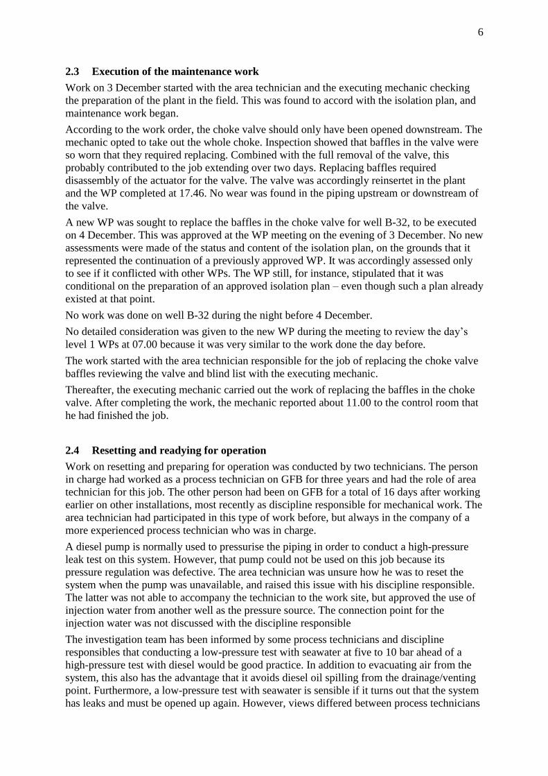
Figure 1 shows the valve positions before resetting and readying for operation. The three-way
valves on the hydraulic system for both the HMV and HWV were placed at that time in
wireline mode1. The needle valves on the hydraulic system were also closed. This ensured
that the HMV and HWV were locked in the closed position during the maintenance work. As
mentioned above, the process technicians had to open the HWV in order to conduct the leak
test. The HMV did not need to be opened, but the Baker panel supplying hydraulics for
opening HMV and HWV has a built-in interlock which means that the opening signal for the
HWV cannot be given until an opening signal has been given for the HMV. Two methods are
available for ensuring that the HMV does not actually open at the signal from the Baker panel.
One is to keep the three-way valve on the HMV in wireline mode, and the other is to keep the
needle valves closed. (These can also be combined.)
Figure 1 Valve positions for resetting and preparing for operation (figure based on
Statoil’s figure)
In this case, however, the technician chose to close the MMV and considered it safe to open
both the HMV and the HWV. One reason for this assessment could be that some shifts use the
MMV as a barrier valve for this type of job. It subsequently emerged that the MMV had a
high internal leak rate.
1 Wireline mode is normally used for work on a well where well service connects and takes over control of the
well valves. This mode is also used to secure valves in the closed position during maintenance work. The
platform’s hydraulic system is thereby isolated from the well valves.

9
Hydraulic pressure from the Baker panel was released up to the closed needle valves. To open
the HMV and HWV, both three-way valves were placed in normal mode. The process
technician then opened the needle valves for both the HMV and the HWV, which resulted in
these two ESD valves going from closed to open position. The sequence of events and timing
for opening the needle valves for the HMV and the HWV is somewhat unclear. Opening both
the HMV and the HWV allowed gas to flow through the leaky MMV and past the Xmas tree.
That caused gas to leak from an open drainage point. The time was then about 14.00. Figure 2
shows valve positions when the leak started.
Figure 2 Valve positions when the leak started
The area technician realised immediately that a leak had occurred somewhere, but did not
know whether it involved injection water or hydrocarbons. In an attempt to stop the leak, the
needle valves were closed. This meant that the HWV and the HMV were locked in the open
position because the hydraulic pressure keeping the valves open could not be bled off from
the control room or through automatic ESD. As a result, the leak lasted about an hour. If the
needle valves had not been closed, the HMV and the HMV would have responded to the ESD
signal and the leak halted within one-two minutes. One explanation for shutting the needle
valves could be the level of stress experienced by the process technician in the circumstances,
and the fact that the leak had begun precisely after the needle valves were opened. He sought
to reverse this by re-closing the valves. It is uncertain whether the three-way valve was
operated at this time. The status of the three-way valve is of no significance as long as the
needle valves are closed and the end piece of the hydraulic connector was plugged.

10
Figure 3 Estimated status of the needle valves and three-way valves immediately after
the leak began
The technicians now attempted to establish what had happened, and moved towards the leak
point. This meant that one of them was exposed to gas. As soon as they realised that this was
a gas leak, the two withdraw from the area.
The alarm went and all personnel mustered in accordance with alarm instructions. All
personnel on board had been accounted for by 14.19.
At 14.55, it was decided to enter M14 in order to open the needle valves for the HMV and the
HWV so that the hydraulic pressure could be bled off and these ESD valves closed. At that
point, none of the gas detectors showed readings above alarm limits.
11
3 The actual and potential consequences of the incident
3.1 Consequences of the actual course of events
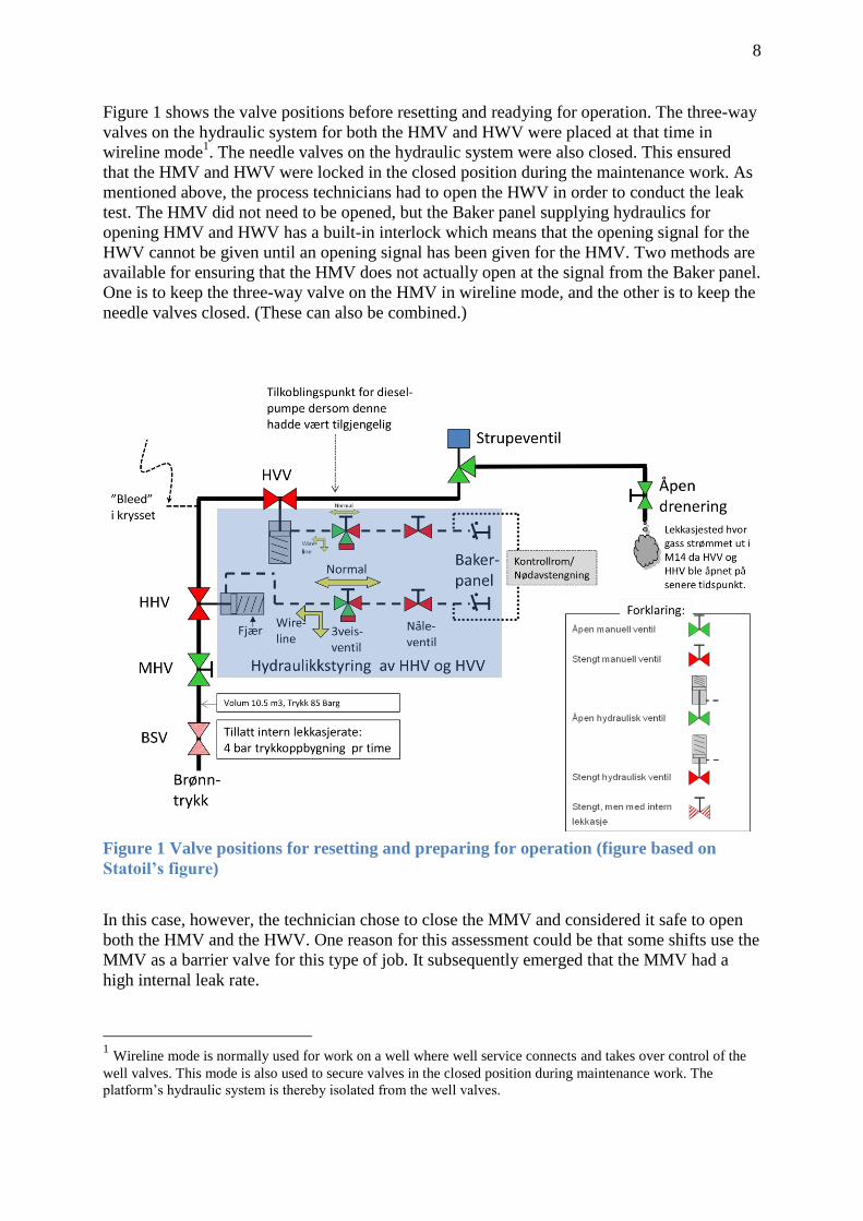
The following were the actual consequences of the incident.
Leak/emission of roughly 800 kg of gas2 in the M14 North Mezzanine Deck Manifold
area (Fire Area 66). Most of the leak was probably methane gas.
The initial rate of leakage from the leak point has been estimated at 1.3 kg/s2.
Gas detectors in the M14 North Mezzanine Deck Manifold area (FA66) indicated gas
concentrations up to 170 per cent of the lower explosion level (LEL)3.
In all, gas was detected in six of eight fire areas in module M14. Alarms (low or high)
were registered from 29 of 32 detectors in these six fire areas.
Exposure of the area technician to hydrocarbon gas, without identified personal injury
as a result.
Lost/deferred production during the period GFB was shut down.
Discharge of 48 cu.m of Arctic Foam 203 (three per cent AFFF) to the sea from
activation of the deluge system (chemical in the black category4).
Estimated oil spill of 25 litres to the sea5.
3.2 Potential consequence of the actual leak
The following are considered to be the potential consequences of the leak.
3.2.1 Personnel involved
The two technicians directly involved in the work could have suffered serious injury or been
killed if the gas had ignited. The probability of ignition is estimated to have been in the order
of one per cent.
The bulk of the leaked gas was probably methane, but there was also a potential for the leaked
medium to contain hydrogen sulphide (H2S) gas. Breathing hydrogen sulphide or hydrocarbon
(HC) gas can cause injury and, in the most serious cases, death. The potential consequences of
breathing such gases depend on such factors as the length of exposure as well as the
concentration and type of HC gas.
2 Calculated/estimated by Statoil with the aid of the Hysys programme for process calculations. Where the leak
volume is concerned, the investigation team has taken into account that some gas has flowed past the downhole
safety valve during the period of the leak. 3
The actual gas concentrations present at the gas detectors could in reality have been both somewhat higher and
lower than the level which can be trended from detector readings during the incident. The reason for this relates
to the relative response between actual leaked gas and the detectors’ defined sensitivity/calibration gas. 4
Reported by Statoil. This is included as an actual consequence because the use of foam to reduce blast loads
was probably without benefitutility when combating the incident. 5
Emerges from the notification received by the PSA from Statoil in connection with the incident. The reason for
the oil spill was probably that the tank for open drainage became filled with water from the deluge system, and
some oil already present in this tank was carried with the discharge to the sea.

12
3.2.2 Other personnel in the area
It has not emerged that other people were present in M14 when the accident happened.
However, this was largely by coincidence. Possible other personnel in M14 would have been
exposed to more or less the same potential consequences as described for the people directly
involved.
3.2.3 Potential consequences of ignition – given the actual leak
Had the leak ignited, it could have caused a fire or explosion with consequent fire. Possible
consequences of an explosion or fire in M14 depend on a number of conditions. These
include:
the size and concentration of a flammable gas cloud in M14
the leak rate as a function of time, total duration of the leak and total available leak
volume
the level of possible accidental loads should ignition occur and which equipment
might be exposed to accidental loads
how main safety functions are maintained or influenced during accidents6
barrier functions established for M14 and associated performance standards for the
barrier elements intended to realise these functions, such as:
o which accidental loads (design accidental loads) firewalls, load-bearing
structures, equipment and safety functions in the module are dimensioned to
tolerate in order to prevent escalation/spreading
o available area for blast relief (louvre panels, explosion panels, gratings,
openings to the outside air)
o passive fire protection of walls, load-bearing structures and equipment to
prevent escalation to other areas or spreading to other equipment
o the presence and effect of deluge water to reduce blast loads, reduce fire
intensity and/or cool down equipment
o ESD and sectioning to reduce emission volumes
o pressure reduction to reduce emission volumes or limit escalation risk
barrier functions established for other areas in order to reduce the consequences of
possible spreading out of M14 and to secure escape/evacuation
6 Section 9 of the management regulations (acceptance criteria for major accident risk and environmental risk)
stipulates that the operator must set acceptance criteria for major accident and environmental risk. Such criteria
must be set in part for the loss of main safety functions as stipulated in section 7 of the facilities regulations. The
latter defines the following main safety functions which must be maintained in an accident:
a) preventing escalation of accident situations so that personnel outside the immediate accident area are
not injured
b) maintaining the capacity of load-bearing structures until the facility has been evacuated
c) protecting rooms of significance to combatting accidents so that they remain operative until the facility
has been evacuated
d) protecting the facility's secure areas so that they remain intact until the facility has been evacuated
e) maintaining at least one escape route from every area where personnel are found until evacuation to the
facility’s safe areas and rescue of personnel have been completed.
Norsok Z-013 - Annex B provides more information/guidance on calculating the associated loss of main safety
functions.
13
the technical condition of barrier elements (safety systems, safety functions and
safety-critical equipment) which realise barrier functions7
ensuring that the use of the installation accords at all times with its technical condition
and the assumptions for use set by risk analyses and so forth8.
Figures/illustrations used in the discussion of the incident’s potential consequences are
provided below and on the following pages .
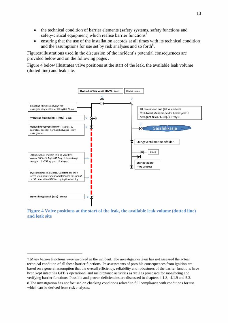
Figure 4 below illustrates valve positions at the start of the leak, the available leak volume
(dotted line) and leak site.
Figure 4 Valve positions at the start of the leak, the available leak volume (dotted line)
and leak site
7 Many barrier functions were involved in the incident. The investigation team has not assessed the actual
technical condition of all these barrier functions. Its assessments of possible consequences from ignition are
based on a general assumption that the overall efficiency, reliability and robustness of the barrier functions have
been kept intact via GFB’s operational and maintenance activities as well as processes for monitoring and
verifying barrier functions. Possible and proven deficiencies are discussed in chapters 4.1.8, 4.1.9 and 5.3.
8 The investigation has not focused on checking conditions related to full compliance with conditions for use
which can be derived from risk analyses.
14
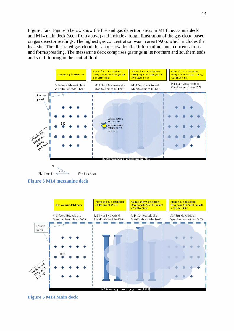
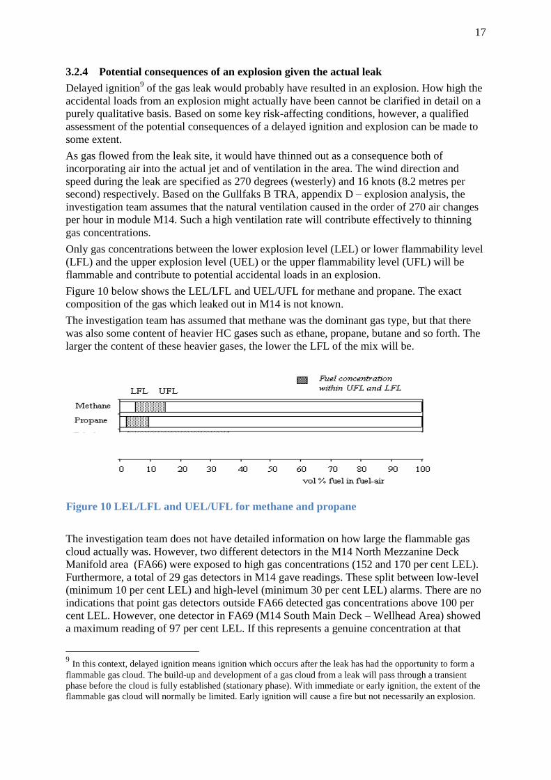
Figure 5 and Figure 6 below show the fire and gas detection areas in M14 mezzanine deck
and M14 main deck (seen from above) and include a rough illustration of the gas cloud based
on gas detector readings. The highest gas concentration was in area FA66, which includes the
leak site. The illustrated gas cloud does not show detailed information about concentrations
and form/spreading. The mezzanine deck comprises gratings at its northern and southern ends
and solid flooring in the central third.
Figure 5 M14 mezzanine deck
Figure 6 M14 Main deck

15
Figure 7 below shows the fire and gas detection areas in M14 (seen through the firewall from
M13) and includes a rough illustration of the leak site, leak direction and the gas cloud in the
module, based on gas detector readings. The highest gas concentration was in the FA66 area,
which includes the leak site. As mentioned above, the mezzanine deck comprises gratings at
the northern and southern ends and solid flooring in the central third. The main and BOP
decks (the roof of M14) have solid flooring
The illustrated gas cloud does not show detailed information about concentrations and
form/spreading.
Figure 7 shows fire and gas detection areas in M14 (seen through the firewall from M13)

16
Figure 8 below shows the static blast loads which the wall between M14 and M13 is designed
to withstand. The figure is for the mezzanine deck, but is similar for the main deck.
Figure 8 Static blast load which the wall between M14 and M14 is designed to withstand
Figure 9 below shows the fire divisions at main deck level. An H0 division separates M14 and
M13. The same applies on the mezzanine deck.
Figure 9 Fire divisions at the main deck level
17
3.2.4 Potential consequences of an explosion given the actual leak
Delayed ignition9 of the gas leak would probably have resulted in an explosion. How high the
accidental loads from an explosion might actually have been cannot be clarified in detail on a
purely qualitative basis. Based on some key risk-affecting conditions, however, a qualified
assessment of the potential consequences of a delayed ignition and explosion can be made to
some extent.
As gas flowed from the leak site, it would have thinned out as a consequence both of
incorporating air into the actual jet and of ventilation in the area. The wind direction and
speed during the leak are specified as 270 degrees (westerly) and 16 knots (8.2 metres per
second) respectively. Based on the Gullfaks B TRA, appendix D – explosion analysis, the
investigation team assumes that the natural ventilation caused in the order of 270 air changes
per hour in module M14. Such a high ventilation rate will contribute effectively to thinning
gas concentrations.
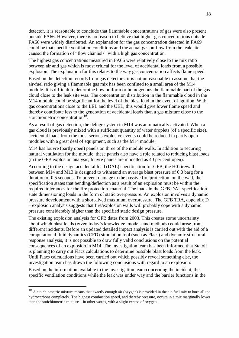
Only gas concentrations between the lower explosion level (LEL) or lower flammability level
(LFL) and the upper explosion level (UEL) or the upper flammability level (UFL) will be
flammable and contribute to potential accidental loads in an explosion.
Figure 10 below shows the LEL/LFL and UEL/UFL for methane and propane. The exact
composition of the gas which leaked out in M14 is not known.
The investigation team has assumed that methane was the dominant gas type, but that there
was also some content of heavier HC gases such as ethane, propane, butane and so forth. The
larger the content of these heavier gases, the lower the LFL of the mix will be.
The investigation team does not have detailed information on how large the flammable gas
cloud actually was. However, two different detectors in the M14 North Mezzanine Deck
Manifold area (FA66) were exposed to high gas concentrations (152 and 170 per cent LEL).
Furthermore, a total of 29 gas detectors in M14 gave readings. These split between low-level
(minimum 10 per cent LEL) and high-level (minimum 30 per cent LEL) alarms. There are no
indications that point gas detectors outside FA66 detected gas concentrations above 100 per
cent LEL. However, one detector in FA69 (M14 South Main Deck – Wellhead Area) showed
a maximum reading of 97 per cent LEL. If this represents a genuine concentration at that
9 In this context, delayed ignition means ignition which occurs after the leak has had the opportunity to form a
flammable gas cloud. The build-up and development of a gas cloud from a leak will pass through a transient
phase before the cloud is fully established (stationary phase). With immediate or early ignition, the extent of the
flammable gas cloud will normally be limited. Early ignition will cause a fire but not necessarily an explosion.
Figure 10 LEL/LFL and UEL/UFL for methane and propane
18
detector, it is reasonable to conclude that flammable concentrations of gas were also present
outside FA66. However, there is no reason to believe that higher gas concentrations outside
FA66 were widely distributed. An explanation for the gas concentration detected in FA69
could be that specific ventilation conditions and the actual gas outflow from the leak site
caused the formation of “flow channels” with a high gas concentration.
The highest gas concentrations measured in FA66 were relatively close to the mix ratio
between air and gas which is most critical for the level of accidental loads from a possible
explosion. The explanation for this relates to the way gas concentration affects flame speed.
Based on the detection records from gas detectors, it is not unreasonable to assume that the
air-fuel ratio giving a flammable gas mix has been confined to a small area of the M14
module. It is difficult to determine how uniform or homogenous the flammable part of the gas
cloud close to the leak site was. The concentration distribution in the flammable cloud in the
M14 module could be significant for the level of the blast load in the event of ignition. With
gas concentrations close to the LEL and the UEL, this would give lower flame speed and
thereby contribute less to the generation of accidental loads than a gas mixture close to the
stoichiometric concentration10
.
As a result of gas detection, the deluge system in M14 was automatically activated. When a
gas cloud is previously mixed with a sufficient quantity of water droplets (of a specific size),
accidental loads from the most serious explosive events could be reduced in partly open
modules with a great deal of equipment, such as the M14 module.
M14 has louvre (partly open) panels on three of the module walls. In addition to securing
natural ventilation for the module, these panels also have a role related to reducing blast loads
(in the GFB explosion analysis, louvre panels are modelled as 40 per cent open).
According to the design accidental load (DAL) specification for GFB, the H0 firewall
between M14 and M13 is designed to withstand an average blast pressure of 0.3 barg for a
duration of 0.5 seconds. To prevent damage to the passive fire protection on the wall, the
specification states that bending/deflection as a result of an explosion must be within the
required tolerances for the fire protection material. The loads in the GFB DAL specification
state dimensioning loads in the form of static overpressure. An explosion involves a dynamic
pressure development with a short-lived maximum overpressure. The GFB TRA, appendix D
– explosion analysis suggests that fire/explosion walls will probably cope with a dynamic
pressure considerably higher than the specified static design pressure.
The existing explosion analysis for GFB dates from 2003. This creates some uncertainty
about which blast loads (given today’s knowledge, models and methods) could arise from
different incidents. Before an updated detailed impact analysis is carried out with the aid of a
computational fluid dynamics (CFD) simulation tool (such as Flacs) and dynamic structural
response analysis, it is not possible to draw fully valid conclusions on the potential
consequences of an explosion in M14. The investigation team has been informed that Statoil
is planning to carry out Flacs calculations to determine possible blast loads from the leak.
Until Flacs calculations have been carried out which possibly reveal something else, the
investigation team has drawn the following conclusions with regard to an explosion:
Based on the information available to the investigation team concerning the incident, the
specific ventilation conditions while the leak was under way and the barrier functions in the
10
A stoichiometric mixture means that exactly enough air (oxygen) is provided in the air-fuel mix to burn all the
hydrocarbons completely. The highest combustion speed, and thereby pressure, occurs in a mix marginally lower
than the stoichiometric mixture – in other words, with a slight excess of oxygen.

19
M14 module, the most likely conclusion is that accidental loads from a possible explosion
would not have exceeded the loads which blast/fire dividers and equipment in M14 can
withstand with regard to preventing the loss of main safety functions.
3.2.5 Potential consequences of a fire given the actual leak
Ignition of the leak would (in addition to a possible explosion) have caused a fire.
An ignited gas leak with an initial rate of 1.3 kb/s (85 barg drive pressure, about 800 kg of
total emitted volume) would have caused a jet fire of a form dependent on the
equipment/objects which might be exposed to it.
The pressure history of the incident is shown in Figure 11 below. This shows that the pressure
between the HMV and the HWV halved in about seven minutes. The form of the pressure
reduction curve is rather unusual, but that could be because the leak opening in the MMV was
not uniform throughout the course of events, or because of special flow conditions. Based on
the detected gas concentrations in FA66, where the leak occurred, the investigation team has
assumed that the leak rate had declined considerably from its initial condition after seven to
10 minutes.
Figure 11 Pressure between the HMV and the HMV during the leak period
Based on the location and orientation of the leak, there is no reason to assume that well
piping, including wellheads, would have experienced lengthy and direct exposure to flames.
However, piping and manifolds from each well would have been directly exposed. The
wellstream in M14 has a high water cut, averaging 80 per cent, which would greatly reduce
the risk of fire. To prevent a lengthy fire or unacceptable escalation risk from arising,
however, it is crucial that ESD valves for each well (DSV, HMV and HWV) close and are
acceptably tight. In its investigation of the incident, the PSA found that Statoil has not tested
these valves in accordance with its own procedures, or in a way which fully verifies that all
relevant performance criteria for the valves are actually met. This is discussed in chapter 5.3.
During the incident, the central control room initiated manual pressure reduction of segments
in modules adjoining M14. The decision to implement this risk-reducing measure was
important in reducing the escalation risk in the event of ignition.
The deluge system in M14 was activated automatically with confirmed gas detection in order
to dampen possible explosion loads. In the event of a fire, the cooling effect of the water is
important.
According to the DAL specification for GFB, the main load-bearing structure for M14 must
be designed to withstand a hydrocarbon fire for two hours. The maximum permitted steel

20
temperature is given as 400°C. The heat flow from a fire can have an intensity of up to 340
kW/sq.m.
Based on the above-mentioned conditions, it is reasonable to assume that barrier elements in
M14 are sufficient to handle/withstand relevant fire loads in a way which prevents the loss of
main safety functions.
3.2.6 Probability of immediate/delayed ignition in M14 given the actual leak
Immediate ignition
The leak opening in this case was an open end piece (diameter 20 mm). In other words, the
leak did not occur as the result of a sudden “fracture mechanism” in equipment. The
probability of immediate ignition as a result of the actual leak is accordingly regarded as
small.
Delayed ignition
The larger a flammable gas cloud becomes, the more the probability of ignition normally rises
because of exposure to a larger number of potential ignition sources. The duration of the
exposure of an area to flammable gas also affects the probability of ignition. However, the
ignition probability is normally by far the highest in the first minute or two after the leak
occurs (in part because of delayed tripping/isolation of equipment/activities, and because a
possible fault usually makes its presence felt relatively quickly).
Gas concentration distribution in the flammable gas cloud also affects ignition probability.
The highest gas concentrations measured in M14 were relatively close to the mix ratio
between air and gas which is most critical in terms of the necessary ignition energy.
Based on detection readings from gas detectors, it has been assumed that an air-fuel ratio
giving a flammable gas cloud has been confined to a small area of the M14 module. M14 is
classified as zone 2, and all equipment in the area is Ex-proofed. Automatic ESD II was
implemented at a relatively early stage in the course of events (which includes
shutdown/isolation of equipment). No particular activities which could have increased
ignition probability were ongoing in M14 when the leak started.
The above-mentioned conditions significantly reduced the probability of delayed ignition.
However, some probability of delayed ignition will always be present in incidents which
cause an explosive gas cloud to form. Assessing ignition probability in risk analyses normally
utilises a general statistical database and specific assessments for the relevant plant. Figures
used to assess the probability of delayed ignition for leak rates of one-two kg/s in naturally
ventilated classified areas are normally in the order of one per cent. That accords with the
ignition probabilities in the GFB risk analysis for M13. This analysis has assumed a lower
ignition probability for M14. Since this apparently assumes that the leak/emission contains 80
per cent water, the investigation team’s assessment is that this is not relevant for the specific
leak in M14.
Data from the trends in risk level in the petroleum activity (RNNP) surveys between 1996 and
2009 (see the main RNNP report, NCS – 2009) show that none of the reported hydrocarbon
leaks above 0.1 kg/s have ignited. The last leak above this level to be ignited on the NCS was
in 1992. Ninety-two leaks greater than 0.1 kg/s occurred on the NCS in 1996-2009. These
data indicate that the ignition probability is relatively low for most hydrocarbon leaks. One
explanation is that Norwegian regulations and the petroleum industry pay great attention to
barrier functions intended to prevent the ignition of hydrocarbon leaks.
Comparing the Norwegian continental shelf (NCS) with the UK continental shelf (UKCS)
shows that more ignited leaks occur on the latter, calculated per installation-year. One-two per

21
cent of gas and two-phase leaks on the UKCS ignite. Statistically significant variances are
found between ignition probabilities on the NCS and UKCS. No obvious explanation exists
for this variance.
The investigation team would emphasise that given the presence of a gas cloud which could
cause the loss of main safety functions in the event of ignition, a limited ignition probability
would nevertheless involve a big risk. This is because risk is influenced by both probability
and consequence. A substantial consequence could therefore yield a considerable total risk
even though the probability of its occurrence is low.
3.3 Potential consequences given different circumstances
The following are considered to be the potential consequences of the incident under only
slightly different circumstances.
3.3.1 Potential consequences of a higher leak rate or greater total emission volume
In its GL0131 guideline, Statoil states in general terms that the maximum size of a gas cloud
is a good indicator of the risk potential of a gas leak. “The risk potential increases steeply as
the size of the cloud increases ... To simplify this: It can be said that the risk potential of a gas
cloud A which is 10 times the size of a gas cloud B (LEL volume) is more than 100 times that
of B. The size of the gas cloud is therefore an appropriate parameter when we wish to classify
an emission according to risk potential. There is clearly a close relationship between the size
of a gas emission and the size of the cloud. This relationship is somewhat complex, as there
are several factors at play. The most important factors are the nature of the emission (rate
over time, jet/impulse or diffuse), geometry/arrangement, fixtures and fittings,
ventilation/wind direction and wind force.” The investigation team agrees with this general
description and assessment of the risk contribution.
The actual leak rate into M14 was not restricted by the open end piece (of roughly 20 mm),
but was probably determined by the internal leak rate through the MMV for well B-32. This
valve had been closed ahead of the leak, but did not stay tight. The MMV was not part of the
blind list or the work description, and had not been leak-tested. The acceptance criterion for
the internal leak rate which well valves in normal operation are tested against is 25.5 cu.m/h
for gas (in other words, 20 kg/h or about 0.006 kg/s for gas with a high methane content). In
this case, the MMV had an internal leak rate which permitted an emission rate of about 1.3
kg/s to the atmosphere. This exceeds the normal test requirement by a factor of more than
200. The investigation team assumes that, under slightly different circumstances, a larger
internal leak rate could have occurred through the MMV than was actually the case.
If the leak rate had only been controlled by the leak opening of about 20 mm, the leak rate
with a drive pressure of 85 barg would have been substantially larger. An initial leak rate
close to four kg/s is not unrealistic in such a case. In a number of cases, a gas cloud could
increase more than proportionally with the emission rate. It is highly probable that a leak rate
of close to four kg/s would have caused a large explosive gas cloud to build up in M14 under
the prevailing ventilation conditions, and accordingly have represented an explosion risk with
a substantial major accident risk.
Where the risk of fire is concerned, a higher leak rate would have meant a greater spread of
flame. At the same time, its duration would have been considerably reduced because the
pressure of the available leak volume through the leak site would have declined more swiftly.
It is difficult to say how this would have affected the course of events overall, but escape
opportunities for personnel possibly present in M14 would probably have been very limited.

22
A small internal leak rate through the DSV would have meant a pressure of roughly 85 barg
building up over about 35 hours between the DSV and HMV. If the work of restoring the
plant had begun at a later time, this pressure could have built up to a substantially higher level
(maximum containment pressure for B-32 was afterwards measured at 215 barg, according to
Statoil’s investigation report).
How a higher pressure between the DSV and the MMV might have influenced the leak rate to
the atmosphere in M14 depends on how the pressure increase would have influenced the leak
rate through the MMV. But it is reasonable to assume that the initial leak rate could, under
slightly changed circumstances, have been considerably higher (up towards nine kg/s,
according to Statoil’s investigation report). It can also be concluded that the emission quantity
and duration of the leak would have increased with a higher available pressure. In total, this
would have meant a significant increase in the fire and explosion risk.
3.3.2 Potential consequences of less wind or a different wind direction
Wind direction and speed during the leak are given as 270 degrees (westerly) and 16 knots
(8.2 m/s) respectively. A substantially lower wind speed or a less favourable wind direction
(from the south-west, in other words) would have reduced natural ventilation in M14. That
would again have allowed the flammable/explosive gas cloud to spread further and thereby
increased the explosion risk.
3.3.3 Potential for increased discharge to the sea
If the leak had ignited and if this had caused supplementary leaks (from manifolds, for
instance), the potential would have existed for considerably larger oil discharges to the sea
than actually occurred.
Foam supplies to the deluge system were halted manually because the stock of foam was
approaching a level which would have meant that GFB fell below the minimum volume
required for normalisation and restart after the leak. Had this not been done, the foam
discharge to the sea would have been substantially larger than it actually was.
23
3.4 Summary of the incident’s potential
Potential given the actual leak
Personnel present in M14 could have suffered serious injury or been killed if the gas had
ignited.
Potential given a larger leak
The investigation team takes the view that, under slightly different circumstances, a leak to
the atmosphere could have occurred at a substantially higher leak rate. If the leak had not been
limited by the MMV, but was only controlled by the leak opening of about 20 mm, the initial
leak rate could have been up towards four kg/s.
Under slightly different circumstances, the pressure between the DSV and the MMV could
have been significantly higher than was actually the case when the leak started. A potential
course of this kind could also have caused a substantial increase in the initial rate of leakage
to the M14 module (up towards nine kg/s, according to Statoil’s investigation report).
Generally speaking, both the cloud size and its probability of ignition increase with a rising
leak rate. A significantly higher leak rate than was actually experienced might very probably
have led to the build-up of a large explosive gas cloud in M14, and thereby represented an
explosion risk with a substantial major accident potential.
In all, a high probability for a flammable gas cloud in large parts of M14 and an ignition
probability in the order of one per cent would have resulted in a substantial risk because of the
very serious accident consequences which could result were the energy potential in the gas to
be released by an explosion.
24
4 Observations
The PSA’s observations can be divided into three categories.
Non-conformances: this category presents observations which the PSA regards as a breach
of the regulations.
Improvement points: related to observations where deficiencies are seen, but without
sufficient information to be able to establish a breach of the regulations.
Conformances/barriers which functioned: refers to established conformances with the
regulations.
When stating the grounds for non-conformances/improvement points, reference is made to the
regulations which applied at the time of the gas leak. For information, it can be noted that the
provisions to which reference is made have been maintained in the new regulations which
came into effect on 1 January 2011, at which time the former regulations were withdrawn.
Reference to the new regulations are given in brackets with each reference to legal authority.
4.1 Identified non-conformances
4.1.1 Deficient planning of the work
Non-conformance
Requirements for planning the work were not complied with – the isolation plan had serious
deficiencies.
Grounds
The isolation plan is a key part of the basis for safe work on pressurised hydrocarbon-bearing
systems. Statoil’s internal requirements (Apos OMM 05.07.01no Prepare and reset for work
on normally pressurised system) sets requirements for the preparation and approval of
isolation plans. The following deficiencies have been identified in the isolation plan prepared
for the work.
When working downstream of well barriers, the requirement for double safety applies,
with two (2) barrier elements in series where depressurisation has been assured
between the elements. The acceptance criterion for internal leaks in these two barrier
elements is zero (0). (Ref Apos.)
The isolation plan identified the HWV as a barrier valve in the work package (ref the
valve and blind list). However, no requirements were established for leak testing of
this valve in the isolation plan, nor has any such test been conducted to check the
internal leak rate.
Hose connections included in the isolation plan were not marked on the P&ID. Apos
(Ref. K-19019) stipulates that the isolation plan must include hose connections which
are marked on the P&ID.
The operational systems manager has only formally signed and approved for
“preparing” in the checklist for maintenance work. An approval signature for
“implementation” of the plan is lacking.
The valve and blind list which forms part of the isolation plan lacks signatures.
(However, it was reported on GFB that the list was approved orally.)
According to Apos (Ref K-19019), the isolation plan must include a checklist after
maintenance work. Before resetting begins, the planned work operation must be

25
verified and formally approved. The section of the plan which deals with resetting was
not used. The page in the plan for “checklist after maintenance work” is blank.
The WP approved before the isolation plan had been prepared was conditional on the
existence of an approved plan. This condition meant that no opportunity was provided
in the WP approval process to verify the quality of the isolation plan which was
prepared. Nor in this case was the condition specified in the WP followed up by those
who approved the WP.
Preparing and resetting are not described in the WP or in the isolation plan, only the
actual inspection and maintenance job. According to Apos OMM 05.01no, only
normal operational operations can generally be performed without a WP.
The isolation plan was prepared and adopted without the above-mentioned conditions being
picked up. This indicates that understanding and expertise were lacking on requirements for
work on normally pressurised systems, and that the overall workload on key individuals set
practical limits on opportunities for adequate follow-up, quality control and verification to
identify errors and deficiencies. See also non-conformance 5.1.7 on capacity and expertise.
Requirements
Activities regulations, section 27 (new section 29) on planning, which states that the party
responsible shall ensure that important contributors to risk are kept under control, both
individually and collectively.
Management regulations, section 9 (new section 12) on planning, which states in part that the
resources required to carry out the planned activities shall be placed at the disposal of
project and operational organisations.
Management regulations, section 10 (new section 13), on ensuring that the work processes
and the products thereof fulfil the requirements relating to health, environment and safety.
4.1.2 Deficient testing of barrier valves identified in the isolation plan
Non-conformance
Deficient test of barrier valves. The HWV was not tested, and the HMV test was conducted
with the wrong acceptance criteria.
Grounds
Apos (work process-oriented management) is Statoil’s tool for managing work processes,
including on GFB. K-27019 is a section of Apos which deals with acceptance criteria towards
the natural environment and in work downstream from well barriers. Double safety is required
for work downstream from well barriers, with two (2) barrier elements in series where
depressurisation has been assured between the elements. WR0256 describes leak criteria for
well valves in normal operation.
The isolation plan identified the HMV as a barrier valve in the work package and stipulated
that this valve had to be leak-tested. However, the leak test conducted with the HMV was
measured against acceptance criteria for an internal leak rate which are used for well barriers
in normal operation. When the plant is to be opened to the atmosphere downstream of the well
barriers, the acceptance criterion for internal leaks is zero (0).
Failure to comply with management requirements stipulated in Statoil’s governing documents
has been established.
The HWV was identified as a barrier valve but not tested, nor does the isolation plan
indicate that it should be tested.
26
The HMV was not tested against the acceptance criterion specified in K-27019 for
internal leaks = zero (0). On the contrary, the leak test on the HMV applied acceptance
criteria for internal leak rates used with well barriers in normal operation.
The HWV was not confirmed to be tight ahead of the HMV test. This created
uncertainty over the HMV test. WR0256 stipulates that tests of the HMV require the
HWV to be tight.
The test conducted on the HMV was carried out with a differential pressure of only 26
barg, instead of a minimum of 70 barg as stipulated in the Statoil procedure. The leak
criteria used by Statoil for the HMV test are stipulated in WR0256. This states that a
maximum pressure build-up of 51 barg over 10 minutes represents an acceptable leak
rate through the HMV in normal operation. When the differential pressure applied was
only 26 barg, the practical consequence is that the acceptance criterion would never be
breached.
Requirement
Management regulations, section 10 (new section 13), on ensuring that the work processes
and the products thereof fulfil the requirements relating to health, environment and safety.
4.1.3 Deficient planning and preparing of leak testing
Non-conformance
Leak testing of the plant was not planned and conducted in a way which met the requirements
and ensured an acceptable execution of the work.
Grounds
Before restoring the plant, Apos requires that flanges which have been loosened/opened must
be leak tested. The following deficiencies have been identified in relation to this work.
No procedure or guidelines exists which describe how leak testing with injection water
should be conducted.
Leak testing and resetting were not covered in the isolation plan.
The diesel pump should normally have been used for leak testing. Because of pressure
regulation problems, it could not be used. The plan was to use injection water from
another well for leak testing instead. This change was clarified orally with the
discipline responsible process, but the connection point for the injection water was not
clarified.
The chosen connection point in the valve cross between the HMV and the left-hand
HWV meant that barrier elements included in the original isolation plan had to be
opened. At the same time, the plant was open to the atmosphere via the 20 mm end
piece downstream from the choke. These conditions meant a change in conditions and
the introduction of new risk elements in relation to the original WP and isolation plan.
During the interviews, it emerged that process technicians in the field “were free” to open
“existing barriers” by establishing new barriers. In such circumstances, it was claimed, one
would not necessarily verify the tightness of the new barriers again leaks. In the investigation
team’s opinion, the isolation plan must be updated if leak testing is conducted “outside” the
original plan, both to ensure a good work process and so that planned work has been cleared
in safety terms before being executed.
Using the MMV as a barrier valve when restoring the plant did not provide double safety with
two (2) barrier elements in series where depressurisation has been assured between the
elements. Pressure conditions between the DSV and the MMV were not assessed or verified.
27
The MMV was used as a barrier valve during leak testing of flanges without being included in
the original isolation plan and without being tested for its internal leak rate. A test of this
valve would have identified that it had a very high leak rate and that a gas volume was
confined between the DSV and the Xmas tree (see also chapter 5.1.5).
Requirements
Management regulations, section 10 (new section 13) on ensuring that the work processes
and the products thereof fulfil the requirements relating to health, environment and safety.
Activities regulations, section 22 (new section 24) on procedures: the party responsible shall
establish criteria for when procedures are to be used as means to prevent faults and
situations of hazard and accident. It shall be ensured that procedures are established and
used in such way as to fulfil their intended functions.
Activities regulations, section 28 (new section 30) on actions during conduct of activities,
which stipulates that planned activities shall be safety cleared before they are conducted. The
safety clearance shall show which conditions have to be met, including the actions required to
be taken before, during and after the work so that those who participate in or may be affected
by the activities are not injured, and so that the probability of mistakes that can result in
situations of hazard and accident is reduced.
Management regulations, section 2 (new section 5) on barriers, which shall be known what
barriers have been established ... and what performance requirements have been defined ... It
shall be known which barriers are not functioning or have been impaired.
4.1.4 Deficient risk assessment
Non-conformance
Risk related to pressure build-up between the DSV and the HMV was not identified or
assessed when planning and executing the work. A risk assessment related to continuing the
same type of work with choke valves after the incident was deficient.
Grounds
Pressure between the DSV and HMV had built up to 85 barg during the period from the leak
test of the DSV until the time of the leak test and reset of the plant.
The risk of this happening was not known to the people involved in the job of leak testing and
resetting the plant.
The shift reports for the production day shift on 4 and 5 December indicate that a choke
inspection was planned for B-25 on Monday 6 December despite the B-32 incident. In the
interview, it was reported that the chief safety delegated had to go to the vice president for
Gullfaks to have this job postponed.
Requirement
Activities regulations, section 27 (new section 29) on planning, which states that in the
planning of activities on the individual facility the party responsible shall ensure that
important contributors to risk are kept under control, both individually and collectively.
4.1.5 Leak in the manual master valve (MMV)
Non-conformance
Deficient maintenance of the MMV so that it had a large internal leak.
Grounds
The MMV on well B-32 has had an internal leak rate which exceeds the acceptance criterion.
The high leak rate to the atmosphere is only explicable if the MMV had a high internal leak
28
rate. Statoil has not observed the manufacturer’s recommended maintenance intervals (ref
Statoil’s investigation report).
The last test conducted on the MMV was dated 20 June 2010. The test passed the acceptance
criterion defined in Apos for well valves in operation. Some people have stated in interviews
that they knew this valve was leaking before the incident.
It is also said that this type of valve must be closed fully on the wheel and then given a
quarter-turn back to remain tight. Others say that this does not apply for the specific valve (the
MMV on B-32). Some also say that it (B-32) must be closed with a pipe wrench to remain
tight. No notification of this exists. The problem was unknown to those directly involved.
This well has suffered considerable problems with scale. That has made it difficult to secure
leak tests of the DSV which meet the acceptance criterion. This could be part of the reason for
the problems with the MMV.
Requirements
Activities regulations, section 42 (new section 45) on maintenance, which stipulates that the
responsible party shall ensure that facilities or parts thereof are maintained, so that they are
capable of carrying out their intended functions in all phases of their lifetime..
Activities regulations, section 44 (new section 47) on maintenance programme, which
stipulates that fault modes which constitute a risk to health, environment or safety shall be
systematically prevented by means of a maintenance programme. The programme shall
comprise activities for monitoring of performance and technical condition, which will ensure
that fault modes that are developing or have occurred, are identified and corrected.
4.1.6 Deficiencies in the emergency shutdown system
Non-conformance
Parts of the ESD system can be unintentionally put out of action in a way which prevents
ESD valves shutting on signal, and which also means that the valves cannot return to safe
condition if a fault occurs.
Grounds
The system for management and control of well valves is complex. This relates partly
to opening sequences and requirements for valve operation, the difference between the
hydraulic system in wireline or normal mode, and the needle valves installed in the
hydraulic system. Taken together, this complexity can increase the probability of
human error – in part because the needle valves installed on the hydraulic lines to well
valves can hinder both ordinary ESD and fail-safe functions. See Figure 12.
When well valves are in normal mode, the needle valves must always be in the open
position. If the latter are shut while the associated ESD valve is open, it will not be
possible to shut the ESD valves from the control room or via the automated ESD
system (valve positions on the needle valves are “secured” only by tape/Velcro).
Needle valves installed on hydraulic lines to well valves are not entered in the P&IDs
and are not tagged. The investigation team has not verified whether preventive
maintenance programmes exist for these valves.
No text or labelling in the field provides information that these needle valves can
prevent ESD valves closing on signal.

29
Figure 12 The hydraulic system for the HWV and the HMV on well B-32
The investigation team was informed by interviewed personnel out on GFB that
incidents related to the hydraulic system for management and control of well valves
had also occurred before, and that these affected the ESD function of well valves.
Requirements:
New facilities regulations, section 33, which stipulates that the emergency shutdown system
shall be designed so that it enters or maintains safe conditions if a fault occurs that can
prevent the system from functioning. The emergency shutdown system shall have a simple and
clear command structure ...
See also the earlier regulations:
Regulations for production and auxiliary systems on production installations etc for
exploitation of petroleum resources in Norwegian internal waters, in Norwegian territorial
waters and in the parts of the continental shelf which is under Norwegian sovereignty. Issued
by the Norwegian Petroleum Directorate 3 April 1978 with later amendments, latest 1 July
1980, pursuant to Royal Decree of 9 July 1976, cf Delegation of Authority made by the Royal
Norwegian Ministry of Industry and Handicraft 12 July 1976.
8.5 Functional tests
The emergency shutdown system shall be designed so that it can be tested when the
installation is in operation. It is the responsibility of the licensee to develop and follow a
procedure to ensure that block valves, bypass possibilities, etc, installed within the emergency
shutdown system are locked in a safe position when operating the installation.
30
4.1.7 Failure to ensure sufficient capacity and expertise
Non-conformance
Sufficient capacity and expertise were not secured for planning and executing the resetting
work. Certain posts and assignments had a heavy workload, and an imbalance existed
between the level of activity and available capacity. The roles of those involved were not
explicitly clarified.
Grounds
It was reported in interviews with a number of people that the work of restoring the plant
should normally be carried out by two experienced process technicians, and that the discipline
responsible process should also review the work together with these before it started. Two
process technicians with knowledge of the plant and experience of leading this type of work
were not available when B-32 was to be reset, and the discipline responsible was also unable
to provide adequate follow-up of planning or execution of the work.
It emerged through conversations that the discipline responsible in this case had no time to go
through the work with the technicians, so that contact was limited to a brief conversation on
using injection water instead of the diesel pump. There was no discussion of where the water
should be connected or which valves should be opened or closed – in other words, how the
change affected the barrier position.
One of the process technicians performing the resetting of the plant was familiar with GFB.
However, he had never previously had the role of leading such work but had participated in it
under the leadership of another process technician. The other worker was an experienced
process technician, but was a newcomer to GFB where he had been for a total of 16 days in
the course of three tours (six, seven and three days) in order to receive installation-specific
training. He had still not been allocated a mentor to take charge of this training.
The expertise of the workforce is determined by a self-assessment, with each worker placing
themselves in one of four categories – from 0 meaning no expertise, 1 some expertise, 2 able
to work independently and 3 able to train others. Discipline responsibles are not involved in
quality assurance of this self-assessment. The system is used to plan personnel composition
for day-to-day activities. In this case, somebody self-assessed as category 2 had been assigned
to lead the work and give installation-specific training to a newcomer.
Which roles the two process technicians should play in performing the work was not
explicitly clarified in the preparations. The combination of an experienced process technician
without installation-specific training and a younger person with such expertise but with no
experience of leading this type of work could, by their own admission, have contributed to
unclear communication and lack of mutual clarification about how the job was to be done.
The newcomer reacted to the way the job was done, but pointed out that it was difficult as a
new arrival to intervene and comment in such circumstances.
Neither of the two process technicians had attended training courses on land for work on
pressurised systems. It has been confirmed that they had received Apos training for work on
pressurised systems, but this training was characterised in interviews as very poor.
Where the system for following up Apos training is concerned, the investigation team has
been told (see e-mail from Statoil dated 2 February 2010) that some entities are a little unclear
about whether reviews of Apos in plenary sessions or personal training is reported. It has also
been reported that GFB lacked an overview of which Apos packages have been taken earlier
by people who came from other installations.
The two process technicians with discipline responsible roles involved in planning the work
had not taken Apos training for work on pressurised systems. But both had taken training
31
courses in such work on land. The operations and maintenance manager had not taken the
training course for work on normally pressurised systems.
The WP was accepted despite an insufficient decision base (no isolation plan). None of the
managers on board had identified deficiencies in the isolation plan before work started:
the unavailability of the diesel pump was not addressed
the connection point for hoses during leak testing was not entered on the P&ID
test in connection with opening the plant was based on acceptance criteria for testing
well valves in operation
risk related to pressure build-up was not identified.
The fact that none of these conditions were picked up during quality assurance could indicate
a lack of expertise and/or capacity in the leadership.
During the meeting to review the level 1 WPs at 07.00 on 3 December 2010, it was proposed
to delay this job because of the generally high level of activity and the burden on control room
operators and process technicians. It was resolved to execute the work order as planned. The
point was made during interviews that the backlog in preventive maintenance had increased
greatly over the past year, and that additional personnel had been sent out to reduce this.
Postponement of the job in question would have meant that the planned work could not be
carried out, with a consequent increase in outstanding work on “red”. This was the
background for management’s decision to carry out the work as planned, even though
capacity in the operations department to follow up jobs was not tailored to the high workload.
Plans after the incident to continue with the same type of work on B-25 suggests a strong
focus on maintaining the adopted work schedule without assessing whether capacity was
sufficient to keep the risk under control. See also chapter 5.1.4.
It was reported in interviews with a number of people that being a specialist process manager
is a demanding job11
. In addition to the role of specialist adviser/trainer in the discipline, they
11
DPN operations – organisation, management and control OMC01, version 1 1 Jan 2011: managerDiscipline responsible process offshore
defines the role of specialist adviser/training within their discipline through active paticipation and execution of work in the external areas
and the central control room (CCR)
makes suggestions for the department’s expertise development within their own discipline
assists the operations and maintenance and preventive maintenance managers as required o discharges other professional duties given priority by the operations and maintenance head
attends meetings in accordance with work processes (see the portal for DPN – everyday collaboration structure)
makes suggestions on the work order plan
facilitates the greatest possible job transfer to the operational team
rotates to land for periods up to 12 months
the job is a specialist post without resource responsibility
participates actively in the conduct of the work and the daily operation of the CCR
identifies M1, M5, Y2 and Y3 notifications and transfers these to land for further processing
quality assures M2 notifications for maintenance
job preparations for the discipline in cooperation with the land organisation o prepares work orders and work permit applications o requisitions materials for work orders o coordinates planning activities with other disciplines/departments o contributes actively to the preparation and quality assurance of isolation/flushing/blinding plans o coordinates specialist personnel in accordance with the plans made and priorities set the manager
makes preparations for planned jobs during equipment shutdowns
punches out in their own discipline in accordance with the work process on modifications
Specialist process manager night shift: in addition to the above-mentioned points:
manages operations on the basis of priority tasks, safety and regularity
checks and reviews work permits for the following day
contributes actively to the preparation and quality assurance of morning/daily reports
32
must discharge a large number of administrative duties and attend fixed daily meetings in the
collaboration structure on the installation and in relation to land. The job of specialist adviser
is exercised through active participation in and execution of the work in external areas and in
the central control room. It is also the case on GFB that these personnel must also discharge a
role as control room operator. This means that they often fail to get out and about because of
meetings, control room work and other administration. The investigation team was told in
interviews that the need to train new personnel has recently been considerable, without
sufficient resources to follow them up properly.
Working conditions for discipline responsibles process seem to inhibit opportunities to pursue
sufficient follow-up of personnel and quality control of planned work operations.
The discipline responsibles process are among the four Statoil personnel on GFB who have
worked the most hours. They put in more than 600 hours from 1 September to 4 December.
That compares with an average of 380 hours to be worked under the pay agreement and a
normal working time of 488 hours pursuant to the framework regulations. Although this could
be within the maximum working hours during a year stipulated in the framework
regulations12
, the investigation team nevertheless sees a possibility that it could breach the
provision in the Working Environment Act which states that working time should make it
possible to take care of safety considerations. This has not been analysed in more detail by the
team.
Requirements
Management regulations, section 11 (new section 14) on manning and competence
The party responsible shall ensure adequate manning and competence in all phases of the
petroleum activities, cf. the framework regulations section 10 (new section 12) on
organisation and competence. There shall be set minimum requirements to manning and
competence in respect of functions
a) where mistakes may have serious consequences in relation to health, environment and
safety,
b) which shall reduce the probability of failures and situations of hazard and accident
developing further, cf. section 1 (new section 4) and section 10 (new section 13).
In the manning of the various work tasks it shall be ensured that the personnel is not assigned
tasks that are incompatible with each other.
The prerequisites that form the basis for the defined manning and competence, shall be
followed up.
When changes in manning take place, possible consequences for health, environment and
safety shall be reviewed.
Work Environment Act, section 10-2 on working hour arrangements
(1) Working hours shall be arranged in such a way that employees are not exposed to adverse
physical or mental strain, and that they shall be able to observe safety considerations.
Activities regulations section 19 (new section 21) on competence
12
Section 37 of the framework regulations on ordinary working hours stipulates that these shall not exceed 12
hours per day (24-hour period) and an average of 36 hours per week over a period of maximum one year. The
investigation team has not checked working time for the whole year and can accordingly draw no conclusions on
this point
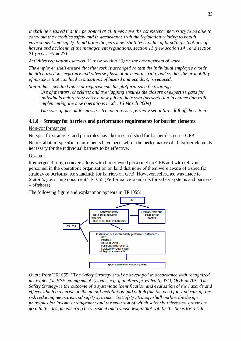
33
It shall be ensured that the personnel at all times have the competence necessary to be able to
carry out the activities safely and in accordance with the legislation relating to health,
environment and safety. In addition the personnel shall be capable of handling situations of
hazard and accident, cf the management regulations, section 11 (new section 14), and section
21 (new section 23).
Activities regulations section 31 (new section 33) on the arrangement of work
The employer shall ensure that the work is arranged so that the individual employee avoids
health hazardous exposure and adverse physical or mental strain, and so that the probability
of mistakes that can lead to situations of hazard and accident, is reduced.
Statoil has specified internal requirements for platform-specific training:
Use of mentors, checklists and overlapping ensures the closure of expertise gaps for
individuals before they enter a new job on their own (presentation in connection with
implementing the new operations mode, 16 March 2009).
The overlap period for process technicians is reportedly set at three full offshore tours.
4.1.8 Strategy for barriers and performance requirements for barrier elements
Non-conformances
No specific strategies and principles have been established for barrier design on GFB.
No installation-specific requirements have been set for the performance of all barrier elements
necessary for the individual barriers to be effective.
Grounds
It emerged through conversations with interviewed personnel on GFB and with relevant
personnel in the operations organisation on land that none of them were aware of a specific
strategy or performance standards for barriers on GFB. However, reference was made to
Statoil’s governing document TR1055 (Performance standards for safety systems and barriers
– offshore).
The following figure and explanation appears in TR1055:
Quote from TR1055: “The Safety Strategy shall be developed in accordance with recognized
principles for HSE management systems, e.g. guidelines provided by ISO, OGP or API. The
Safety Strategy is the outcome of a systematic identification and evaluation of the hazards and
effects which may arise on the actual installation and will define the need for, and role of, the
risk reducing measures and safety systems. The Safety Strategy shall outline the design
principles for layout, arrangement and the selection of which safety barriers and systems to
go into the design, ensuring a consistent and robust design that will be the basis for a safe
34
operation of the installation. Operational aspects shall be addressed in the Safety Strategy,
which then should serve as an input to the development of the operational procedures. The
Safety Strategy shall reflect installation specific conditions, e.g. environment and climate,
competence of staff, cultural elements, infrastructure such as transport, telecommunications
and health care, availability of supplies of water and electricity, etc. Emergency preparedness
aspects shall also be covered by the Safety Strategy. The principles applied in ISO 13702 and
ISO 17776 is considered applicable. Detail requirements to the various safety systems shall
be covered by specifications established for each particular system. The principles of the
Safety Strategy shall be governing for the development of the performance standards and
specifications.” (underlinings by the investigation team.)
The above-mentioned description of the safety strategy in TR1055 and its relationship to both
risk/hazard assessment and performance standards accord with the regulatory requirements
and the guidelines to the regulations.
Where performance requirements and standards are concerned, TR1055 states the following:
“On the basis of the generic performance standards described herein there shall be
developed specific performance standards for each installation. The specific performance
standards and their performance requirements should be derived from the generic
performance standards and safety strategy to reflect country and local rules and regulations
and local practise differences … For existing installations see chapter 1.2. The safety
performance standards shall form the basis for safety system elements performance which
should be sustained and verified through the lifecycle of the installation. The specific safety
performance standards shall ensure that barriers, safety systems or safety functions:
Is suitable and fully effective for the type hazard identified
Has sufficient capacity for the duration of the hazard or the required time to provide
evacuation of the installation
Has sufficient availability to match the frequency of the initiating event
Has adequate response time to fulfil its role
Is suitable for all operating conditions.”
The above-mentioned description of specific performance standards (including performance
requirements) in TR1055 and the relationship between these and the Safety Standard accord
with the regulatory requirements and the guidelines to the regulations.
TR1055, chapter 1.2, deals with how the document is to be applied on existing installations:
“For existing installations, identified non-conformities between original design requirements
and requirements within TR1055 shall be treated as potential risk reducing measures and
included in the ALARP process … Identified non-conformities shall be documented in
dispensation system. The development of a facility specific safety strategy, including facility
specific performance standards for safety systems, shall be approved in the dispensation
system and be warranted in this document.”
It is the investigation team’s understanding that this requirement means that gaps between the
original design and the requirements in TR1055 should be assessed as potential risk-reducing
measures and included in the “as low as reasonably practicable” (Alarp) process. Such use of
TR1055 is important for ensuring “continuous improvement”, but does not fulfil the
regulatory requirement that specific strategies and performance requirements must also be
established for existing installations (see the management regulations and the associated
guidelines). The regulations and guidelines stipulate that the strategy must be shaped to give
relevant employees a shared understanding of the basis for the requirements set for each
35
barrier, including the relationship between specific risk and hazard assessments for the
individual installations and the requirements about and for barriers.
The investigation team has been informed that GFB has granted itself an exemption from the
requirement to establish specific strategies and performance requirements. The company has
not applied to the PSA for an exemption from the regulatory requirement. In the investigation
team’s opinion, such an application should have been made because the way TR1055 is
practised does not fulfil the regulatory requirements for specific strategies and performance
standards.
The lack of a specific safety strategy and specific performance requirements contributes to
inadequate knowledge among personnel on GFB about which functions all barriers or barrier
elements should fulfil. A condition which illustrates this relates to the use of foam with deluge
water when the latter is used to dampen an explosion (see chapter 5.2.2). Chapter 4.1.9
contains other examples of uncertainty related partly to a lack of specific performance
requirements and documentation which confirms/verifies that these requirements are met.
Requirement
Management regulations, section 2 (new section 5) concerning barriers: the operator or the
one responsible for the operation of a facility, shall stipulate the strategies and principles on
which the design, use and maintenance of barriers shall be based, so that the barrier function
is ensured throughout the life time of the facility. It shall be known what barriers have been
established and which function they are intended to fulfil, cf section 1 (new section 4), and
what performance requirements have been defined in respect of the technical, operational or
organisational elements which are necessary for the individual barrier to be effective.
4.1.9 Explosion risk, design accidental loads (DAL specification)
Non-conformance
Statoil has not adequately updated risk analyses which provide a nuanced and integrated
picture of the explosion risk and which clarify conditions for use. Nor has it been documented
that the risk associated with explosions has been reduced as far as possible.
Grounds
Uncertainty exists (given today’s knowledge, models and methods) concerning the blast loads
which can arise, the DALs for all relevant barrier elements, and how the latter will withstand
design loads. To meet the regulatory requirements, it is necessary to know which accidental
loads the installation or parts of it could be exposed to in the event of a design incident. It
must also be possible to document that established barrier elements can withstand these loads
for the necessary length of time. More specific grounds for the non-conformance are given
below.
DAL specification
The DAL is defined in Norsok S-001 as: “most severe accidental load that the function or
system shall be able to withstand during a required period of time, in order to meet the
defined risk acceptance criteria”.
The investigation team has assessed the DAL specification for Gullfaks B. This document is
dated 1985 (version 6A).
The GFB DAL includes a recommended static design pressure of 0.3 barg with a duration of
0.5 seconds to ensure the integrity of firewalls against blast. Requirements are also specified
for the maximum permitted deflection to ensure the integrity of passive fire protection on
firewalls. Design loads for drag or negative impulse are not covered.
36
The TTS’s M2.2 performance requirement in PS 15 Explosion Barriers states:
“Relevant documentation for operation shall be available and updated:
Total Risk Analysis & Emergency Preparedness Analysis (explosion studies)
Fire and Explosion Strategy (including HAZOP, DAL etc.)
Design Accidental Load specification (DAL)”
In the TTS verification note from 2005, the following is specified in relation to this
requirement: “The DAL specification is not updated, but available in STID. New blast
calculations show that the design load from an explosion accord with area loads given in the
DAL. As a result, an update is not necessary as a result of blast pressure calculations”.
TTS’s F 1.2 performance requirement in the same PS states: “Check that the dimensioning
loads are defined for relevant local horizontal and vertical area dividers (pressure and
impulse from explosion) and equipment (drag forces). This also includes safety critical
equipment”. The TTS verification note related to this requirement states: “No dimensioning
loads are specified for safety critical equipment”.
The investigation team has noted that the DAL specification for GFB has not been updated in
such a way that DALs for safety-critical piping and equipment are specified. Not has the DAL
specification been updated to provide references to the whole decision base underlying the
applicable DALs.
Static overpressure versus dynamic pressure development
The loads in the GFB DAL specification state dimensioning loads in the form of static
overpressure. An explosion involves a dynamic pressure development with a short-lived
maximum overpressure. Structural response to a blast load will depend on the size of the load
as a function of time and the structure’s characteristics. Calculating structural response in
relation to blast loads is described in Norsok N-004, A.6. On the basis of the documentation
submitted, the investigation team has not seen a GFB-specific structural analyses which
document that dimensioning dynamic blast loads would not cause the loss of main safety
functions. Basing the design of firewalls in GFB on static blast loads appears to involve a
degree of uncertainty. The regulations require uncertainty to be reduced.
Effect of deluge in explosion analyses
The applicable risk analysis for GFB is dated 2 June 2003 and includes an explosion analysis.
This identifies a substantial risk-reducing effect for the most serious explosive development if
the fixed deluge system is released before ignition occurs. The current facilities regulations
require the fixed deluge system to be automatically activated in the event of gas detection if
this can reduce blast pressure. As with applicable requirements for designing passive fire
protection, however, the intention of the regulations is that the effect of fire-fighting
equipment should not be taken into account when designing facilities and equipment to
withstand blast loads. In the GFB explosion analysis, the effect of deluge has been taken into
account when calculating the frequency for loss of explosion barriers (loss of main safety
functions). Quote from GFB TRA appendix D – explosion analysis: “Since this updating of
the TRA is to reflect actual conditions on GFB, explosion simulations have been run with
deluge specifically for GFB”. The following is stated in chapter PS 15.4.8 explosion design
principles in TR 1055: “The effect of automatically released deluge may be taken into account
when establishing the dimensioning explosion load if the calculation method takes into
account the reliability, availability and efficiency of the deluge system”.
The investigation team cannot see that the explosion analysis has taken account of the
reliability/availability aspect, or those cases in which the explosion occurs so quickly that the
blast loads are generated before the deluge system is activated or effective. To be able to

37
argue in favour of taking account of the effect of deluge in relation to establishing DALs and
making assessments of the frequency for loss of main safety functions, a distinction must be
drawn for explosions which occur before the deluge system is activated or sufficiently
effective. This can be done in part by taking account of response times for the gas detection
system, the start-up time for the fire pumps and the time taken before each deluge system can
deliver water in quantities effective enough to reduce blast loads. The investigation team
would point out here that a general experience with ignition probability models is that a
relatively high proportion of the total ignition probability occurs in the first minute after a leak
starts. Another point is that studies/reports after incidents have often shown that gas detection
systems were overbridged (partially disabled) when the leak occurred. (That was the case, for
example, with the gas leak on Heidrun on 11 October 2010.) This could significantly delay
deluge start-up and release.
When the favourable effect of deluge is taken into account, as in the GFB explosion analysis,
it must be possible pursuant to TR1055 to document that the conditions and performance
requirements assumed for the deluge system are expressed in a clear manner and are further
documented and complied with during the operations phase. The investigation group has been
unable to identify in the documentation submitted that this has been adequately done. A
specific example is related to the necessary fire pump capacity in connection with explosion
damping. For the deluge to have a favourable effect on damping blast loads, a normal
assumption is that water droplets are distributed throughout the spatial volume occupied by
the gas cloud and where the explosion would occur. The investigation team’s understanding
of the position on GFB is that a dimensioning “gas scenario” will include deluge activation
throughout M14, and that this corresponds to the “largest plus largest adjacent area” in
relation to barrier scenarios.
In the TTS context, the following emerges from the documentation submitted to the PSA:
From 2001: The dimensioning fire area is not segregated from other areas with
firewalls. The largest defined area is M14 N wellhead area, BOP deck North plus the
manifold areas (M14N and M14S), i.e. M14S wellhead area is not included in the fire
area even if there are no walls separating M14S from M14N. No study supporting two
different fire areas in M14 North and South has been identified. The firewater pump
capacity is dependent on fire area size and firewater coverage. In addition, the
firewater duty points are not balanced for firewater demands exceeding current 100%
capacity, i.e. 3 electrical firewater pumps.
Status at 3 April 2002: The area is fully tested. That means the dimensioning fire area
plus the largest of the adjacent areas “wall to wall”. Verification point clarified with
the specialist ladder in the base organisation and thereby closed.
Verification note 2005: The point was closed in 2002 in consultation with the base
organisation on the basis that the presence of sufficient capacity in the whole gas
scenario with one pump (diesel-hydraulic) out of action had been verified. During this
partial review (2005), it has not been possible to document results for this test. The
minimum requirement for closing the observation is the conduct of a test which can
document adequate capacity. The test is used to verify the corresponding Pipenet
calculation. When the latter is verified as OK, the calculation is run with a 10%
degraded pipe curve, since this is the acceptance limit for pump capacity.
A further comment is that another consequence of GFB’s dependence on deluge to achieve an
acceptable explosion risk will relate to possible future periods where fire monitors, for
example, is used during modification/maintenance of the ordinary deluge system. This is
38
because it would be difficult to ensure that water droplets are distributed throughout the
spatial volume with fire monitors.
Module geometry used in analyses
The available explosion analysis for GFB dates from 2003. Today’s knowledge shows that it
is crucial to use a sufficiently detailed description of module geometry in explosion
simulations. It emerged from interviews that no adequately updated explosion analysis for
GFB exists today, but that extensive work has already been initiated to establish one.
Potential leak scenarios in M14
The explosion analysis does not reflect the possibility of leaks in M14 which consist primarily
of gas alone. In M14, the analysis assumes that what might leak out would contain large
volumes of water, on average 80 per cent. The leak on 4 December 2010 showed clearly that
substantial escapes which consist more or less entirely of pure gas can occur.
Principles for risk reduction
The TTS observation in 2005 contains the following in connection with PS 15 (explosion
barriers): “A cost-benefit assessment of reducing the frequency for escalation (Alarp) has not
been carried out”. The documentation submitted by Statoil in connection with the
investigation shows that this TTS observation is still not closed.
Requirements
Framework regulations, section 9 (new section 11) on principles relating to risk reduction,
which stipulates in part that harm or danger of harm to people, the environment or to
financial assets shall be prevented or limited in accordance with the legislation relating to
health, the environment and safety, including internal requirements and acceptance criteria.
Over and above this level the risk shall be further reduced to the extent possible. Assessments
on the basis of this provision shall be made in all phases of the petroleum activities. In
effectuating risk reduction the party responsible shall choose the technical, operational or
organisational solutions which according to an individual as well as an overall evaluation of
the potential harm and present and future use offer the best results, provided the associated
costs are not significantly disproportionate to the risk reduction achieved. If there is
insufficient knowledge about the effects that use of the technical, operational or
organisational solutions may have on health, environment and safety, solutions that will
reduce this uncertainty shall be chosen.
Activities regulations, section 23 (new section 25) on use of facilities, which stipulates that
their use shall at all times be in accordance with the technical condition of the facility and the
operational prerequisites stipulated in the risk analyses.
Management regulations, section 2 (new section 5) on barriers, which stipulates in part that it
shall be known what barriers have been established and which function they are intended to
fulfil, and what performance requirements have been defined in respect of the technical,
operational or organisational elements which are necessary for the individual barrier to be
effective. It shall be known which barriers are not functioning or have been impaired. The
party responsible shall take necessary actions to correct or compensate for missing or
impaired barriers.
Management regulations, section 8 (new section 11) on the basis for making decisions and
decision criteria, which stipulates in part that, prior to decisions being made, the party
responsible shall ensure that issues relating to health, environment and safety have been
comprehensively and adequately considered. The decision criteria shall be based on the
stipulated objectives, strategies and requirements relating to health, environment and safety
and shall be available prior to decisions being made. Necessary co-ordination of decisions

39
shall be ensured at the various levels and in the various areas in order to avoid unintentional
effects. Prerequisites that form the basis for a decision, shall be expressed so that they can be
followed up.
Management regulations, section 13 (new section 16) on general requirements for analyses,
which stipulates that the party responsible shall ensure that analyses are carried out, which
provide the necessary decision basis in order to give due consideration to health, environment
and safety. When carrying out and updating the analyses, recognised models, methods and
techniques and the best available data shall be used. The purpose of the individual analysis
shall be made clear, together with the conditions, assumptions and delimitations on which the
analyses are based. The individual analysis shall be presented so that the target groups get a
complete and comprehensive presentation of the results. Analyses shall be updated when
alterations in the conditions, assumptions and delimitations individually or as a whole affect
the results of the analyses, or when other new knowledge of significance to the results of the
analyses exists. Criteria shall be set for updating of analyses. The operator or the one
responsible for the operation of a facility, shall have a complete record of the analyses that
are carried out. Necessary consistency between analyses that are supplementary to or are
based on each other, shall be ensured.
Management regulations, section 15 (new section 17) on quantitative risk and emergency
preparedness analyses, which stipulates in part that quantitative risk analyses which provide
a balanced and as comprehensive picture as possible of the risk shall be carried out. The risk
analyses shall
a) identify situations of hazard and accident, select initiating incidents and map the causes of
the incidents,
b) carry out modelling of accident sequences and consequences so that, among other things,
possible dependencies between physical barriers can be revealed, and so that the
requirements that must be
set in respect of the performance of the barriers, can be calculated,
c) classify important safety systems,
d) show that the main safety functions are adequately provided for,
e) identify dimensioning accidental loads,
f) provide the basis for selecting the defined situations of hazard and accident.
Necessary sensitivity calculations and evaluations of uncertainties shall be carried out.
40
4.2 Improvement potential
4.2.1 Acceptance criteria for the loss of main safety functions
Improvement potential
Clear and unambiguous acceptance criteria have not been established for the loss of main
safety functions.
Grounds
The management regulations stipulate that acceptance criteria must be set for the loss of main
safety function,
In the TTS context from 2005, the following is stated in connection with PS 15, explosion
barriers (underlining by the investigation team):
Status in 2003: “The frequency for the dimensioning blast pressure of 0.3 barg will not
exceed 1 x 10⁻⁴
, but the overall total frequency will exceed 1 x 10⁻⁴
. Since static
tolerances are used for comparison with dynamic blast loads, these frequencies will
most probably be reduced considerably if actual dynamic tolerances are assessed.
This will most probably mean that the overall frequency will fall within the acceptance
criterion. The issue is accordingly regarded as closed.”
Verification note 2005: “The wrong argumentation was used under status for closing
this item. First, the item cannot be closed because it is assumed that one will fall
below a criterion if further analyses are conducted. Second, 10-4
is not an acceptance
criterion, but a dimensioning criterion. This accordingly does not require an
exemption, but an Alarp assessment which looks at the effect of reducing the frequency
for escalation.”
The management regulations stipulate that acceptance criteria must be set for loss of the main
safety functions stipulated in the facilities regulations.
Requirement
Management regulations, section 6 (new section 9) on acceptance criteria for major accident
and environmental risk, which stipulates that the operator shall set acceptance criteria for
major accident risk and environmental risk. Acceptance criteria shall be set for [such aspects
as] the loss of main safety functions as mentioned in section 6 (new section 7) of the facilities
regulations for offshore petroleum activities.
41
4.2.2 Mixing foam in the deluge system for explosion damping
Improvement potential
Clarify the role of foam (AFFF) when this is combined with firewater to be used as a means
of explosion damping.
Grounds
According to Statoil, 48 cu.m of Artic Foam 203 (three per cent AFFF) was used as a result of
the incident and the activation of the deluge system. This was done to reduce blast loads, and
meant that a chemical in the black category was discharged to the sea and that the stock of
foam was substantially reduced. The PSA is not aware that mixing foam in firewater has a
positive effect on reducing blast loads.
Relevant personnel in the GFB land organisation have been unable to explain the decision
base for adding foam to firewater for reducing blast loads. When asked, Statoil has been
unable to provide GFB-specific performance requirements associated with the use of firewater
and foam for explosion damping.
Statoil’s in-depth study after the Heidrun gas leak of 11 October 2011 states: “If deluge were
to be used for explosion damping, the stock of AFFF would be exhausted. AFFF foam does
not have an explosion-damping effect in a gas cloud”.
Requirement
Management regulations, section 2 (new section 5) on barriers, which stipulates that the
operator ... shall stipulate the strategies and principles on which the design, use and
maintenance of barriers shall be based ... It shall be known what barriers have been
established and which function they are intended to fulfil, cf section 1 (new section 4) on risk
reduction, second paragraph, and what performance requirements have been defined in
respect of the technical, operational or organisational elements which are necessary for the
individual barrier to be effective.
Activities regulations, section 57 (new section 66) on the use and discharge of chemicals,
which stipulates that the use and discharge of chemicals shall be reduced as much as
possible.

42
4.3 Deficient testing of barrier valves in normal operation
The following non-conformances which are not directly related to the actual incident on 4
December have been identified by the investigation team.
Tests carried out with well valves on GFB have not always accorded with the
requirements described in Apos OMM 01.07.05.
Valves on the Xmas tree have not always been tested ahead of DSV tests, and have
thereby not been tested in the sequence stipulated by the test requirements.
The differential pressure used in well valve tests has in some cases been lower than
Statoil’s requirement for a differential pressure of 70 bar.
Acceptance criteria for pressure build-up or reduction over the course of 10 minutes,
as stipulated in WR0256 (local supplement for Gullfaks) exceed 70 bar in some cases,
and can accordingly never be breached when using only 70 bar of differential pressure
during testing.
In connection with programme-based maintenance of well valves, valve lubrication
has been practised ahead of valve tests.
Test intervals for hydraulic Xmas tree and wellhead valves have been 12 months,
compared with a maximum of six-monthly test intervals stipulated in Norsok D-010.
These non-conformances are being followed up by the PSA as a separate case, and this
investigation report accordingly provides no detailed grounds and regulatory references
related to the identified conditions.

43
5 Discussion of uncertainties
Statoil’s investigation states that the HMV was opened as a result of erroneous operation of
hydraulic valves. In interviews with those involved, the investigation team was told that the
plan was to open the HMV because the MMV had been closed and this was perceived
together with the DSV as a secure barrier. The investigation team does not consider that this
uncertainty is significant for the course of events or the underlying causes of the incident.
The assessment of the consequences and potential of the incident is based on
estimates/calculations of the amount released, the leak rate, the opening size and so forth. The
figures used in this investigation report have largely been provided to the PSA while the
investigation was underway on GFB. In practice, some uncertainty will always attach to such
estimates/calculations. The values cited for the quantity emitted, the leak rate and opening
size must therefore not be regarded as completely exact. A possible change of 20 per cent in
these figures would not in this case alter the investigation team’s assessments and
conclusions. The information in Statoil’s investigation report does not provide a basis for
amending the conclusions reached on this point.

44
6 Appendices
Appendix A: Timeline
Date Incident/condition Comments
20.6.10 The last test conducted with the manual master valve (MMV) is dated 20 June 2010. The hydraulic master valve (HMV) and the hydraulic wing valve (HWV) are also tested on this date.
This is the last time the MMV is known to have been leak-tested.
The test passed the acceptance criteria defined in Apos for well vales in operation.
It is not known whether the valve has been tested later, but some people have reported that they knew this MMV had a leak before the incident.
It is also said that this type of valve must be closed
fully on the wheel and then given a quarter-turn back to remain tight. Others say that this does not apply for the specific valve (the MMV on B-32). Some also say that it (B-32) must be closed with a pipe wrench to remain tight. No notification of this exists. The problem was unknown to those directly involved.
This well has suffered considerable problems with scale. That has made it difficult to secure leak tests of the downhole safety valve (DSV) which meet the acceptance criterion.
19.9.10 05.10-05.20
An inflow test is conducted with the HMV for B-32.
19.9.10 14.40-15.25
A leak test of the DSV for well B-32.
19.9.10 20.30
Responsibility for well B-32 is transferred from drilling and well to operation and maintenance.
19.11.10 Leak test of the DSV for well B-32.
45
26.11.10 Diesel pump: Undesirable incident with a fluid kick and overpressure in a pipe is registered when using the diesel pump to raise pressure in a flowline for well B-28.
One of the measures is repair of the pressure control for the diesel pump, and a notification of the fault is to be prepared.
Another measure is to inform all shifts that the diesel pump cannot be used for leak tests on flowlines before the control has been repaired and found to be working.
The leak test must be conducted with a different pressure source. In this case, the choice fell on injection water from another well (B-22). Connection was made in the valve cross between the HMV and the HWV. This is outside the isolated area in the valve and blind list.
2.12.10 17.30-19.00
WP for disassembly of the B-32 choke valve for inspection is approved in the meeting to review the next day’s WPs.
Conditional on an approved isolation plan for the work.
Early Friday morning 3.12.10
Preparations for preventive maintenance on the B-32 choke valve.
Work process is described in OMM 05.07.01.01no Prepare normally
pressurised system/equipment for
activity requiring isolation. The work process was introduced a year ago.
2.12.10 19.00 3.12.10 07.00 on night shift
An isolation plan is prepared by a control room operator on night shift.
Requirement that this is approved by the O&M leader (operational systems manager).
2.12.10 23.19
Diesel pump: notification 42318026 is registered for the diesel pressurisation pump. The fault is a failure of the logic for pressure regulation, so that the pump can no longer be used for small volumes.
3.12.10 02.00
Well B-32 is shut down in preparation for preventive maintenance on the choke valve.
No leak test is conducted with the HWV, even though this forms part of the isolation plan as a barrier valve. Nor is leak testing stipulated on the valve and blind list.
Statoil’s investigation report concludes that the MMV was pressure-tested in the opposite direction at the same time as the HMV was tested.
The MMV is not included in the isolation plan for this job. Practice varies between the various shifts on the use of this valve. Some people report that it should be tested and closed in connection with this maintenance job
3.12.10 02.15
Leak test of the HMV. The test is conducted at a differential pressure of 26 bar. Ninety degrees upstream of the valve and 64 bar in the valve cross. The valve is included in the isolation plan as a barrier valve.
Tested against the acceptance criterion which applies for well valves in operation, and not against the requirement for a tight valve which applies for valves included in the DB&B when opening to the atmosphere/natural environment.

46
3.12.10 03.00
Leak test of the DSV for well B-32. The valve is included in the isolation plan.
Norsok D-010: test of the DSV permits a leak of up to 25.5 cu.m per hour, 900 scf/h for gas, and 0.4 l/m for liquid.
3.12.10 04.30-05.05
Water flushing of flowlines to production and test separators.
3.12.10 abt 06.00
Closure of valves after flushing, and preparations completed in accordance with the isolation plan.
3.12.10 06.40
The plan is passed to the day team at the handover meeting.
Brief meeting between night and day shifts – no detailed review.
3.12.10 07.00
WP-1 meeting, where the question of delaying the job is raised on the basis of the generally high level of activity. Decision taken to execute the job.
Possibly because inspectors from land are present and had planned a speedy return home?
3.12.10 08.39
WP 9503002496 is issued for 07.00-19.00 to execute work order 21556945-0020. The WP has the necessary approvals, but formal approval of the isolation plan by the operational systems manager is lacking.
3.12.10 The checklist before maintenance work is reviewed by the process technician with area responsibility (area technician) for the day shift.
3.12.10 The first WP for disassembly of the choke valve for inspection of piping downstream from the valve is executed. The work order states that the choke valve is to be loosened at the one flange. However, both flanges are loosened. The text in the work order is not observed. Baffles in the choke valve are found to be worn and need to be replaced.
3.12.10 17.46
Work order 21556945-0020 concerning disassembly of the choke valve for inspection is completed.
3.12.10 WP 9503005220 is sought for 07.00-19.00 on 4.12.10 to replace baffles in choke valve B-32 on the grounds of observed wear. The WP relates to work order 21556945-0080.
3.12.10 17.30-19.00
The WP is approved at the evening meeting.
3.12.10 19.00- 4.12.10 07.00
No work is carried out in connection with the work order during the night before 4.12.10.
4.12.10 06.40
Handover meeting for production
4.12.10 07.00
WP-1 meeting. Simplified consideration is given to this WP because it is regarded as very similar to the WP reviewed the day before.
4.12.10 08.33
WP 9503005220 is issued for 07.00-19.00 to execute work order 21556945-0080. The WP has the

47
necessary approvals, but formal approval of the isolation plan by the operational systems manager is still lacking.

48
4.12.10 Mechanic and area process technician review the valve and blind list before the mechanic begins to replace baffles.
4.12.10 abt 11.00
Replacement of baffles completed. The mechanic reports that he has completed this job.
4.12.10 The process technician prepares to reset the plant. A job of this kind is normally carried out by two process technicians who are familiar with the plant.
4.12.10 The process technician explains to the discipline responsible that he is uncertain how to implement the reset given that the diesel pump is unavailable as a pressure source. He is given a green light to use injection water from another well as the pressure source.
4.12.10 The area technician is accompanied by an experienced process technician who is new on the installation (three weeks) and thereby unfamiliar with the plant.
4.12.10 A low-pressure test with seawater in the open area is left out.
4.12.10 The leak test of the production piping begins. The two process technicians who are to do the job agree on a leak test by connecting injection water to the valve cross. The bleed line is chosen as the connection point. The pressure of the injection water is choked down to 40 bar.
Hose from B-22 connected to supply injection water for pressure testing. This is connected between the HMV and the HWV in the valve cross. The person concerned believed this to be normal procedure when injection water was to be used.
The valve and blind list does not show where the injection water should be connected.
Apos: requires hose connections to be noted in the valve and blind list.
The discipline responsible believes it is fine to leak-test in this way, but that the connection point should have been the service wing valve.
The HWV and the HMV are both in wireline mode at this point, and are both closed.

49
The MMV is closed. The idea is that the HMV and the HWV will now be opened so that the leak test can be conducted in the opened place.
Some process operators believe that the MMV should have been included in the original isolation statement, and should have been shut. Others believe this should only be used in critical conditions. Use of the MMV appears to be shift-dependent.
The three-way valves on B-32 for the HWV and the HMV are converted to platform mode. The needle valves for hydraulic supply to these valves are still shut.
Hydraulic pressure is released from the Baker panel to the needle valves for the HWV and HMV on B-32.
The HMV and the HWV open with the serving of the needle valves on the hydraulic supply to the actuators for these valves.
4.12.10 14.00
Leak. Volume between the DSV and Xmas tree 10.5 cu.m, about 800 kg gas at 85 barg. Leak rate through the 20 mm opening is governed by the leak rate through the MMV.
The area technician perceives immediately that a leak has occurred somewhere, but does not know whether this involves injection water or hydrocarbons from the well.
In an attempt to stop the leak, the area technician screws shut the two wheels on the needle valves which he has just opened. The fact that these wheels are in the closed positions later turns out to prevent bleeding of hydraulic pressure from the valves, so that these no longer shut at ESD.
4.12.10 14.19
POB OK
4.12.10 14.55
The needle valves on the HMV and the HWV are opened so that the hydraulic pressure can be bled off and the HMV and the HWV closed.

50
Appendix B: Documents used in the investigation
See the Norwegian version for the full list
51
Appendix C: Abbreviations
AFFF Aqueous film forming foams
Apos Work process-oriented management system
CFD Computational fluid dynamics
DAL Design (dimensioning) accidental load
DB&B Double block and bleed
Deluge Dousing with firewater to prevent ignition and dampen
possible blast pressure
DSV Downhole safety valve
ESD Emergency shutdown
FLACS Flame acceleration simulator
HMV Hydraulic master valve
HTO Human – technology – organisation (model for incident
and causal analysis
HWV Hydraulic wing valve
LEL Lower explosion level
LFL Lower flammability level
MMV Manual master valve
NCS Norwegian continental shelf
O&M Operations and maintenance
P&ID Process and instrumentation drawing
PS Performance standard
ROB Routines on board (local work routines and check
lists)
UEL Upper explosion level
V&B list Valve and blind list (part of the isolation plan)
WO Work order
WP Work permit (permission to execute a work order)

52
Appendix D: Overview of people interviewed
(removed from the internet version)