Investigation on the Oil Supply System of a Scroll Compressor
9
Purdue University Purdue e-Pubs International Compressor Engineering Conference School of Mechanical Engineering 2004 Investigation on the Oil Supply System of a Scroll Compressor Micahel M. Cui Trane Air Conditioning Follow this and additional works at: hps://docs.lib.purdue.edu/icec is document has been made available through Purdue e-Pubs, a service of the Purdue University Libraries. Please contact [email protected] for additional information. Complete proceedings may be acquired in print and on CD-ROM directly from the Ray W. Herrick Laboratories at hps://engineering.purdue.edu/ Herrick/Events/orderlit.html Cui, Micahel M., "Investigation on the Oil Supply System of a Scroll Compressor" (2004). International Compressor Engineering Conference. Paper 1684. hps://docs.lib.purdue.edu/icec/1684
Transcript of Investigation on the Oil Supply System of a Scroll Compressor

Purdue UniversityPurdue e-Pubs
International Compressor Engineering Conference School of Mechanical Engineering
2004
Investigation on the Oil Supply System of a ScrollCompressorMicahel M. CuiTrane Air Conditioning
Follow this and additional works at: https://docs.lib.purdue.edu/icec
This document has been made available through Purdue e-Pubs, a service of the Purdue University Libraries. Please contact [email protected] foradditional information.Complete proceedings may be acquired in print and on CD-ROM directly from the Ray W. Herrick Laboratories at https://engineering.purdue.edu/Herrick/Events/orderlit.html
Cui, Micahel M., "Investigation on the Oil Supply System of a Scroll Compressor" (2004). International Compressor EngineeringConference. Paper 1684.https://docs.lib.purdue.edu/icec/1684

C093, Page 1
International Compressor Engineering Conference at Purdue, July 12-15, 2004
INVESTIGATION ON THE OIL SUPPLY SYSTEMOF A SCROLL COMPRESSOR
Michael M. CUI
TRANE Air Conditioning3600 Pammel Creek Road
La Crosse, WI 54601Tel: 608-787-3313, Fax: 608-787-2669, E-mail: [email protected]
ABSTRACT
The startup process of the scroll compressor oil supply system is important for scroll compressor reliability andperformance. Since the bearings are running dry when a scroll compressor starts, the bearing dry time is animportant design parameter as well. When a scroll compressor starts, the oil sump, bearings, and shaft interact witheach other and form an oil supply system. The working mechanism of this oil supply system is complex anddynamic. To characterize the oil supply system and achieve high reliability of scroll compressors, a numerical studyis embarked. The model integrates the oil sump, oil gallery inside the shaft, and bearing system together to definethe major features of the oil supply system. Two operating parameters are studied using the numerical modeldeveloped. The first parameter is the oil depth inside the oil sump. When oil is pumped into the gallery andbearings, the oil sump depth changes gradually with time. This change of depth impacts the lubrication capacity ofthe oil system. Since the sump has an open surface, the surface shape is a function of time and waves form inside thecompressor. These surface waves interact with oil flow inside the gallery and bearings. It is necessary to includethem in the analysis to determine the performance characteristics of the oil supply system. The second parameter isthe fluid viscosity. The change in oil viscosity is caused by refrigerant absorbed in the oil and heat transfer betweenthe motor and oil. A total of four cases are analyzed comparatively. The physical mechanisms controlling oilsupply rate are defined. The oil supply rate and the dry periods of the bearings are obtained. The results can be usedto design and optimize the oil supply system of scroll compressors.
1. INTRODUCTION
The oil flow inside the oil pump and sump is a complex physical process. When a scroll compressor starts, oilremains inside the sump. The bearings and pump are dry. As the motor rotates, the centrifugal force graduallyovercomes gravity and surface tension. The pressure generated by the centrifugal force inside the flow field drivesthe oil into the oil gallery. The shape of the oil surface is determined by the balance of gravity, centrifugal force,and surface tension as well as gas flow above the oil surface. The rising oil level eventually reaches the bearingsand ports. When the oil pressure overcomes the resistance of the bearings and ports, the oil starts flowing intobearings and ports in the system. The oil supply rates to bearings are resulted from design features and workingconditions of oil pump and bearings. The design objective of the oil supply system is to provide sufficient oil to thebearings and minimize the bearing dry period.
Kim et al. (1998) showed the oil flow rate is sensitive to the shape of the oil gallery inside the crack shaft. Cho etal. (2002) and Drost et al. (1992) found the oil flow rate changes with temperature (viscosity). Drost et al. (1992)also obtained the data that indicates the oil flow rate is a function of sump oil level. CFD analyses (Cho et al., 2002and Bernardi, 2000) for the oil flow inside the gallery indicate that the oil supply system may not be filled with oil.These studies reveal the complex nature of the flow physics inside the scroll compressor oil supply system andsuggest the further study of the system. The key elements that need to be included in the oil supply system study arethe oil sump, bearing system, vent, and ports.
The current investigation of the scroll compressor oil supply system starts from the fundamental physics of the oilpumping flows. The study includes the interactions of the oil pump, sump, as well as the bearing system. The

C093, Page 2
International Compressor Engineering Conference at Purdue, July 12-15, 2004
physics in the analysis covers gravity, centrifugal force, and surface tension. The details of the oil supply systemgeometry are included. The study characterizes the physical process controlling the oil supply system anddetermines the effect of the design and operating parameters on the oil supply system performance.
2. METHODOLOGY
The oil supply system is an integrated part of a scroll compressor. Figure 1(a) shows the schematic of a scrollcompressor with the oil supply system. The oil supply system is located in the low-pressure side of the scrollcompressor. Oil is pumped up from oil sump and feeds the lower main, upper main and orbiting bearings. Thereare a few ports connected to the oil gallery to send gas out and discharge the dirt in the system. Figure 1(b) showsthe flow domain in the oil supply system. The lower main and orbiting bearings are end–port fed and the uppermain bearing is side-port fed.
The oil supply system includes three parts: oil sump, oil gallery, and bearings. The multiphase flow regime showsdistinguishable features during the startup process in different parts of the system. The refrigerant gas-oil flowcontains both continuous and dispersed gas and oil phases. To simulate this process, the flow inside the oil supplysystem is treated as a heterogeneous Eulerian-Eulerian multiphase flow. A commercial solver based on the finitevolume method is used for this analysis. The oil in the shaft, including flows in the gallery and feed holes, iscalculated in a rotating frame of reference. The oil sump is calculated in a stationary frame of reference. All thefield quantities are obtained at each time step. The oil supply rates to bearings and ports are also calculated at eachtime step. The shaft starts at 0 rpm and gradually accelerates to 3500 rpm, its maximum speed. Equation 1describes the motor speed variation during the startup process:
,367t,*7378.8 + t*57687 - t*170525
{23
=ϖsradwhensradwhen
/367/367
><
ϖϖ ( 1 )
The rotating speed of the oil pump is shown Figure 2 as a function of time when motor starts at time equals zero.
The initial condition of the numerical simulation is chosen as the start time of the shaft rotation. The oil level isconstant in the sump and shaft when the transient simulation starts. The calculations continue until the oil flowreaches its steady state and is no longer a function of time.
To characterize the performance of the oil supply system at difference working conditions, a total of four cases withdifferent viscosity and sump oil levels are analyzed. The runs are designed as 22 factorial. The parameters of thecases analyzed are listed in Table 1.
Case 1 2 3 4
Viscosity, cp 5 26.4 5 26.4
Oil level, cm 5 5 10 10
Table 1. Parameters of the cases analyzed.
Since the flow inside the bearings has a smaller scale than the flow in other parts of the oil supply system, the oiland gas flows inside the bearings are simulated separately. The total of three bearings is simulated. These bearingscan be classified into two categories. The upper main bearing is simulated as a side-port fed bearing (Figure 3(a)).The lower main and orbiting bearings are simulated as end-port fed bearings (Figure 3(b)). Since both gas and oilgo through the bearings, the oil and gas are simulated separately to obtain the flow characteristics in side-port fedand end fed bearings. The obtained flow characteristics are used in the startup process simulation.

C093, Page 3
International Compressor Engineering Conference at Purdue, July 12-15, 2004
Suction side flowpath
Motor
Check valve
Discharge plenum
Oil sumpOil pump
Compression elements
Bearings
High Pressure
Low Pressure
Inlet
Discharge
(a)
(b) (c)
Figure 1. Schematic of the scroll compressor (a), the geometry of the oil supply system (b), and location ofvent and ports (c).

C093, Page 4
International Compressor Engineering Conference at Purdue, July 12-15, 2004
0
50
100
150
200
250
300
350
400
0 0.05 0.1 0.15 0.2 0.25 0.3
Time, second
Spee
d, ra
d/se
c
scroll compresso speed
Figure 2. Rotating speed of scroll compressor oil pump.
(a) (b)
Figure 3. Side-port fed bearing (a) and end-port fed bearing (b).
3. FEATURES OF FLOW FIELD
The driving forces of the flow inside the oil supply system are centrifugal and gravitational forces as well as surfacetension. These forces induce different features of the flow field during the oil supply system working process.
The first notable feature of the oil flow inside the oil sump is the wave generation and dispersion (Figure 4). Whenflow rate is low at the beginning of the pumping process, the wave is stable with a distribution of the wavelengthproportional to the distance from the shaft. The amplitudes of the waves are similar. As flow rate increases, thewaves generated near the pump inlet are suppressed. The oscillations in the region near the inlet disappear due tothe strong damping induced by the large mean velocity. The amplitude of the waves decays exponentially as thewaves propagate from the shaft.
C093, Page 5
International Compressor Engineering Conference at Purdue, July 12-15, 2004
In the shaft, the oil goes up along the circumference of the pickup tube. After oil reaches above the lower mainbearing, the oil stays in the one side of the gallery that has a larger radius. The oil first rises into the gallery from theoil sump located at the bottom of the compressor. When the oil takes more space in the top cavity the oil starts toflow back down into the oil gallery to fill the rest of the space. The wave in front of the oil flow inside the gallerycan be seen in the Figure 5. The space left in the gallery is located in the upper cavity and lower part of the gallery.This space is eventually filled up simultaneously. It is interesting that the empty space is not filled bottom up.
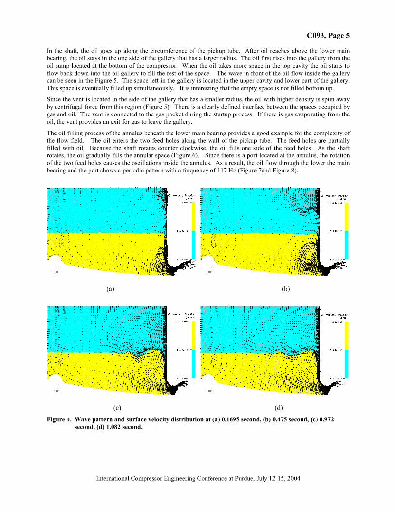
Since the vent is located in the side of the gallery that has a smaller radius, the oil with higher density is spun awayby centrifugal force from this region (Figure 5). There is a clearly defined interface between the spaces occupied bygas and oil. The vent is connected to the gas pocket during the startup process. If there is gas evaporating from theoil, the vent provides an exit for gas to leave the gallery.
The oil filling process of the annulus beneath the lower main bearing provides a good example for the complexity ofthe flow field. The oil enters the two feed holes along the wall of the pickup tube. The feed holes are partiallyfilled with oil. Because the shaft rotates counter clockwise, the oil fills one side of the feed holes. As the shaftrotates, the oil gradually fills the annular space (Figure 6). Since there is a port located at the annulus, the rotationof the two feed holes causes the oscillations inside the annulus. As a result, the oil flow through the lower the mainbearing and the port shows a periodic pattern with a frequency of 117 Hz (Figure 7and Figure 8).
(a) (b)
(c) (d)
Figure 4. Wave pattern and surface velocity distribution at (a) 0.1695 second, (b) 0.475 second, (c) 0.972second, (d) 1.082 second.
C093, Page 6
International Compressor Engineering Conference at Purdue, July 12-15, 2004
Figure 5. Oil fraction as a function of time inside the gallery.
Figure 6. Oil filling process of the annulus beneath the lower main bearing.
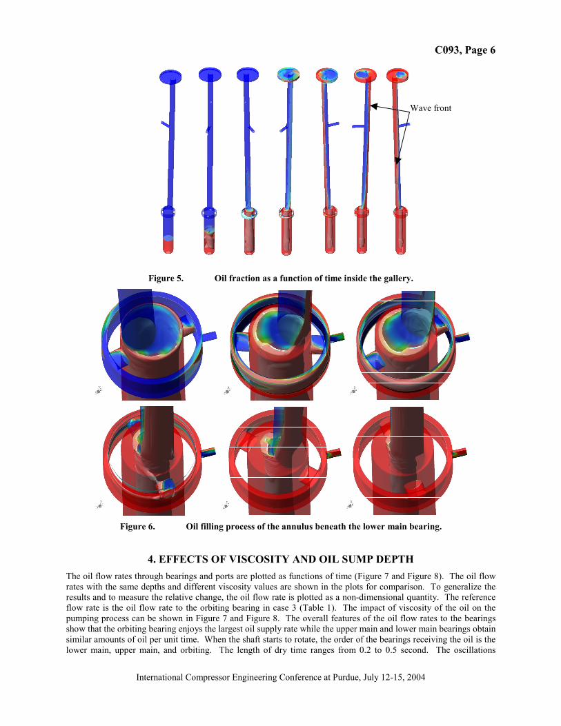
4. EFFECTS OF VISCOSITY AND OIL SUMP DEPTHThe oil flow rates through bearings and ports are plotted as functions of time (Figure 7 and Figure 8). The oil flowrates with the same depths and different viscosity values are shown in the plots for comparison. To generalize theresults and to measure the relative change, the oil flow rate is plotted as a non-dimensional quantity. The referenceflow rate is the oil flow rate to the orbiting bearing in case 3 (Table 1). The impact of viscosity of the oil on thepumping process can be shown in Figure 7 and Figure 8. The overall features of the oil flow rates to the bearingsshow that the orbiting bearing enjoys the largest oil supply rate while the upper main and lower main bearings obtainsimilar amounts of oil per unit time. When the shaft starts to rotate, the order of the bearings receiving the oil is thelower main, upper main, and orbiting. The length of dry time ranges from 0.2 to 0.5 second. The oscillations
Wave front
C093, Page 7
International Compressor Engineering Conference at Purdue, July 12-15, 2004
caused by the oil feed holes on the shaft can be seen in the oil supply rate to the lower main bearing and oil flow ratethrough the port.
After the oil flow reaches its steady state, the oil supply rates to bearings are larger for smaller viscosity value.These results qualitatively agree with the experimental results obtained by Cho et al. (2002) and Drost et al. (1992).Since their test data was obtained without an orbiting bearing, a direct or quantitative comparison is difficult.However, both tests and numerical data point to the same direction: the variation of the oil supply rate to bearingcaused by the viscosity change is small compared to the magnitude of the oil flow rate. Conceptually, lowerviscosity makes it easier for the oil to flow in the gallery and inside the bearings. This provides a physical groundfor the results obtained. A lower viscosity also reduces the bearing dry time (Figure 7 and Figure 8). Themagnitude of the dry time reduction is also in the same order as the total oil supply rate to the bearings. The featuresof the oil supply curves are similar for the upper main and orbiting bearings. The oil supply rates for the lower mainbearing are different for two viscosity values. The oil supply rate for higher viscosity (26.4 centipoises) takes longerto reach its maximum value.
The viscosity also changes the oil flow rate through the ports in the system. The oil flow rate through the port at theannulus below the lower main bearing shows different features. The higher viscosity value makes more oil passthrough the port. This partially results from the lower flow rates through the bearings. The resistances through thebearings are high and the oil takes the least resistance route. The most noticeable feature of oil flow through the portis the periodic oscillation. This phenomenon is caused by the rotation of the feed holes. The magnitude of theoscillation is bigger for lower viscosity cases.
There is very little oil going through the vent (Figure 7 and Figure 8) since the vent is located on the inner side ofthe oil gallery. The centrifugal force is proportional to the radial distance of the oil surface from the shaft centerlineand works against the flow entering the vent. Since the total pressure of the oil flow is generated by the centrifugalforce, the pressure of the oil stream near the vent entrance can not overcome the centrifugal force before the oilreaches the top cavity. Therefore the oil will not enter the vent before the pressure in the system exceeds thecentrifugal force at the entrance of the vent. When oil eventually fills the cavity to the top of the shaft, the oil flowto orbiting bearing is saturated. The pressure starts to build up due to the larger radial distance from the centerlineof the shaft. The static pressure near the vent entrance gradually approaches the centrifugal force at the samelocation. The oil starts to flow into the vent. Figure 7 through Figure 8 indicate the time when oil enters the ventafter the oil supply rate to the orbiting bearing reaches its plateau. For the high viscosity cases, the oil enters thevent earlier since the resistance to the oil flow entering orbiting bearing is higher and pressure builds up quicker inthe oil supply system.
When the oil level in the sump becomes higher, the oil supply rates to the bearings increase. The oil flow throughthe vent and port of the oil supply system also increases when the oil level goes higher in the oil sump. Thesefindings are in line with the experimental results obtained by Drost et al. (1992). Their data shows that the total oilflow rate increases with the oil depth in the sump. The overall profiles of oil supply rates are similar for the twodepths analyzed. However, the bearing dry time is significantly prolonged. The time for oil flow through the port toreach its plateau increases 42%. The overall profiles of the oil flow through the vent and port are similar. The wearand tear of the bearings need to be assessed to obtain a better reliability of the bearing system.
0.0
0.2
0.4
0.6
0.8
1.0
1.2
0.0 0.1 0.2 0.3 0.4 0.5 0.6 0.7 0.8 0.9
Time, sec
Oil
flow
rate
thro
ugh
bear
ings
, Q/Q
ref
Lower main - case 3
Upper main - case 3
Orbiting - case 3
Lower main - case 4
Upper main - case 4
Orbiting - case 4
0
1
2
3
4
5
6
0.0 0.1 0.2 0.3 0.4 0.5 0.6 0.7 0.8 0.9
Time, sec
Oil
flow
rate
thro
ugh
ports
, Q/Q
ref
Port 4 - case 3
Port 1 - case 3
Port 4 - case 4
Port 1 - case 4
(a) (b)Figure 7. Oil flow rate through bearings (a) and ports (b) at the sump oil depth of 10 cm.

C093, Page 8
International Compressor Engineering Conference at Purdue, July 12-15, 2004
0.0
0.2
0.4
0.6
0.8
1.0
1.2
0.0 0.1 0.2 0.3 0.4 0.5 0.6 0.7 0.8 0.9
Time, sec
Oil
flow
rate
to b
earin
gs, Q
/Qre
f
Lower main - case 2
Upper main - case 2
Orbiting - case 2
Lower main - case 1
Upper main - case 1
Orbiting - case 1
0
1
2
3
4
5
6
0.0 0.1 0.2 0.3 0.4 0.5 0.6 0.7 0.8 0.9
Time, sec
Oil
flow
rate
thro
ugh
port
s, Q
/Qre
f Port 4 - case 2
Port 1- case 2
Port 4 - case 1
Port 1- case 1
(a) (b)Figure 8. Oil flow rate through bearings (a) and ports (b) at the sump oil depth of 5 cm.
5. CONCLUSIONSA CFD model for oil supply system of the scroll compressors is developed. This model includes all components ofthe oil supply system and flow physics. The results provide physical insights for the mechanisms controlling thebearing supply system of scroll compressors.
Lower viscosity of the oil that results from refrigerant absorption in the oil and higher temperature increases bearingoil supply rate. The total amount of the oil pumping through the system is also larger.
A lower oil level in the sump reduces the bearing oil supply rate and prolongs the bearing dry time significantly.
NOMENCLATURE
Q flow rate ϖ angular speedt time ref reference value
REFERENCESBernardi, J. D., 2000, CFD simulation of a scroll compressor oil pumping system, Proc. Int. CompressorEngineering Conference at Purdue, pp 707-714.
Cho, H., Yoo, B., Kim, Y., Chung, J.T., 2002, CFD simulation on the oil pump system of a variable speed scrollcompressor, Proc. Int. Compressor Engineering Conference at Purdue, C24-1
Drost, R.T., Quessada, J.F., 1992, Analytical and experimental investigation of a scroll compressor lubricationsystem, Proc. Int. Compressor Engineering Conference at Purdue, pp 551-560.
Kim, D. H., Shin, D,K., and Cho, S.O., 1998, An experimental analysis on the flow rate in scroll compressors, Proc.Int. Compressor Engineering Conference at Purdue, pp 637-642.
ACKNOWLEDGEMENT
The author would like to thank TRANE Air Conditioning, American Standard Companies, for the permission topublish this paper. Jack Sauls of TRANE Air Conditioning provided Figure 1(a), reviewed the manuscript, andprovided stimulating discussions. Brian VanderKooy of TRANE Air Conditioning calculated the motor startupcurve. Mike Chudiak of ANSYS Inc. provided valuable help on the bearing models.


![[17]- Catalogue_2012_EN-Digital Scroll Compressor Catalogue](https://static.fdocuments.in/doc/165x107/55cf9c44550346d033a93ebf/17-catalogue2012en-digital-scroll-compressor-catalogue.jpg)