Investigation of electromagnetic torque production in ...
14
Investigation of electromagnetic torque production in induction motor during charging operation SOHIT SHARMA * , MOHAN V AWARE and APEKSHIT BHOWATE Department of Electrical Engineering, Visvesvaraya National Institute of Technology, Nagpur, India e-mail: [email protected]; [email protected]; [email protected] MS received 10 July 2019; revised 2 May 2020; accepted 15 May 2020 Abstract. Integrated battery chargers (IBCs) provide the flexibility of reusing the electric drive-train com- ponents of the electric vehicle (EV) for the charging operation. The purpose of the paper is to reuse its traction inverter and motor windings as rectifier and grid interfacing filter, respectively for charging and keeping rotor standstill without using any external brake. Various winding configurations are developed by splitting the three- phase induction motor (IM) winding into two parts at zero electrical degree to keep the rotor standstill. The different stator winding connections are proposed for IM which restricts the formation of rotating magnetic field (RMF). Cases are categorized into two parts, in the first part, RMF is cancelled to zero and in the other part, RMF is converted into pulsating magnetic field (PMF). Mathematical investigation for torque production in both cases is provided to prove that the proposed winding connections are incapable of developing electromagnetic torque in machine. Mathematical findings are validated by experimentation on split three-phase IM (STP-IM). This analysis is useful in identifying the nature of torque developed in motor during charging operation of EV. Keywords. Integrated battery charger; filter; winding impedance; pulsating magnetic field; electromagnetic torque. 1. Introduction Battery chargers play a significant role for electric vehicles (EVs). Various battery charger topologies are discussed in [1, 2]. Primarily they are classified as off-board chargers (figures 1(a)) and on-board chargers (figure 1(b)). During conductive charging, on-board driving motor of the EV is stationary and inverter is idle. Hence, the same hardware is used as the charger and is known as integrated battery charger (IBC) as shown in figures 1 ((c) and (d)) where stator windings of machine are used as filter and inverter is used as rectifier. As three-phase supply is being connected to three-phase IM, the rotor of the machine starts rotating. Hence, separate clutch is required to decouple the rotating rotor and wheels of EV as shown in figure 1(c). This method is inefficient as power used for charging the battery is utilized in rotation of IM. The locking of rotor by an external force is also inefficient as it draws high magne- tizing current from the grid [3]. The traction motor of EV could be integrated into the charging process in three ways. In first, traction motor (interior permanent magnet motor) is operated as rotating transformer to provide the galvanic isolation between charger and grid [4, 5]. In a second way, stator windings are used as coupled DC inductor where machine carries the current in stator windings such that rotor becomes standstill [6]. Such types of chargers are developed with permanent magnet synchronous motor (PMSM) [7, 8] for single-phase supply. A three-phase supply based charger is discussed in [9] with PMSM. In third, stator windings are used as a filter between grid and converter. With single-phase supply, electromagnetic torque cancellation process for the machine is similar to the second category [10, 11]. For three-phase supply based chargers, rotor rotation is prevented by reconfiguring the stator windings, ensuring rotor stand-stillness during the charging process as shown in figure 1(d) and the clutch is inessential. The third category of IBC eliminates the need of bulky grid inductive filters. The objective for developing the on-board IBC is to save cost, volume, space and weight in the EV [12, 13]. The first IBC based on SCR was developed for NASA project in 1985 with the major objective of reducing the 50% volume and 30% weight of the first generation inverter power stage [14]. In 2010, on- board charger for EVs based on split-phase motor was introduced by Valeo Power-Train Systems and patented in [15–18]. This charger is based on the three-phase open end topology, where from both side of stator windings, inverters are connected. In such type of chargers, circulating current may flow [19, 20] which causes unwanted losses in the machine windings. The chameleon charger which is com- mercially used in Renault ZOE uses stator windings as DC coupled inductors [21] and its working is based on patents *For correspondence Sådhanå (2020)45:158 Ó Indian Academy of Sciences https://doi.org/10.1007/s12046-020-01393-3
Transcript of Investigation of electromagnetic torque production in ...
Investigation of electromagnetic torque production in induction motorduring charging operation
SOHIT SHARMA* , MOHAN V AWARE and APEKSHIT BHOWATE
Department of Electrical Engineering, Visvesvaraya National Institute of Technology, Nagpur, India
e-mail: [email protected]; [email protected]; [email protected]
MS received 10 July 2019; revised 2 May 2020; accepted 15 May 2020
Abstract. Integrated battery chargers (IBCs) provide the flexibility of reusing the electric drive-train com-
ponents of the electric vehicle (EV) for the charging operation. The purpose of the paper is to reuse its traction
inverter and motor windings as rectifier and grid interfacing filter, respectively for charging and keeping rotor
standstill without using any external brake. Various winding configurations are developed by splitting the three-
phase induction motor (IM) winding into two parts at zero electrical degree to keep the rotor standstill. The
different stator winding connections are proposed for IM which restricts the formation of rotating magnetic field
(RMF). Cases are categorized into two parts, in the first part, RMF is cancelled to zero and in the other part,
RMF is converted into pulsating magnetic field (PMF). Mathematical investigation for torque production in both
cases is provided to prove that the proposed winding connections are incapable of developing electromagnetic
torque in machine. Mathematical findings are validated by experimentation on split three-phase IM (STP-IM).
This analysis is useful in identifying the nature of torque developed in motor during charging operation of EV.
Keywords. Integrated battery charger; filter; winding impedance; pulsating magnetic field; electromagnetic
torque.
1. Introduction
Battery chargers play a significant role for electric vehicles
(EVs). Various battery charger topologies are discussed in
[1, 2]. Primarily they are classified as off-board chargers
(figures 1(a)) and on-board chargers (figure 1(b)). During
conductive charging, on-board driving motor of the EV is
stationary and inverter is idle. Hence, the same hardware is
used as the charger and is known as integrated battery
charger (IBC) as shown in figures 1 ((c) and (d)) where
stator windings of machine are used as filter and inverter is
used as rectifier. As three-phase supply is being connected
to three-phase IM, the rotor of the machine starts rotating.
Hence, separate clutch is required to decouple the rotating
rotor and wheels of EV as shown in figure 1(c). This
method is inefficient as power used for charging the battery
is utilized in rotation of IM. The locking of rotor by an
external force is also inefficient as it draws high magne-
tizing current from the grid [3]. The traction motor of EV
could be integrated into the charging process in three ways.
In first, traction motor (interior permanent magnet motor) is
operated as rotating transformer to provide the galvanic
isolation between charger and grid [4, 5]. In a second way,
stator windings are used as coupled DC inductor where
machine carries the current in stator windings such that
rotor becomes standstill [6]. Such types of chargers are
developed with permanent magnet synchronous motor
(PMSM) [7, 8] for single-phase supply. A three-phase
supply based charger is discussed in [9] with PMSM.
In third, stator windings are used as a filter between grid
and converter. With single-phase supply, electromagnetic
torque cancellation process for the machine is similar to the
second category [10, 11]. For three-phase supply based
chargers, rotor rotation is prevented by reconfiguring the
stator windings, ensuring rotor stand-stillness during the
charging process as shown in figure 1(d) and the clutch is
inessential. The third category of IBC eliminates the need
of bulky grid inductive filters. The objective for developing
the on-board IBC is to save cost, volume, space and weight
in the EV [12, 13]. The first IBC based on SCR was
developed for NASA project in 1985 with the major
objective of reducing the 50% volume and 30% weight of
the first generation inverter power stage [14]. In 2010, on-
board charger for EVs based on split-phase motor was
introduced by Valeo Power-Train Systems and patented in
[15–18]. This charger is based on the three-phase open end
topology, where from both side of stator windings, inverters
are connected. In such type of chargers, circulating current
may flow [19, 20] which causes unwanted losses in the
machine windings. The chameleon charger which is com-
mercially used in Renault ZOE uses stator windings as DC
coupled inductors [21] and its working is based on patents*For correspondence
Sådhanå (2020) 45:158 � Indian Academy of Sciences
https://doi.org/10.1007/s12046-020-01393-3Sadhana(0123456789().,-volV)FT3](0123456789().,-volV)

[22, 23]. For the charging mode, this configuration requires
additional components (rectifier).
According to [24], nowadays IMs are the second choice
for EVs. However, the advantage of using IM as an inte-
grated motor drive over PMSM is that its winding induc-
tance [25] and developed electromagnetic torque [26] are
independent of rotor position. The limited IBC solutions
using three-phase IM with three-phase inverter are pre-
sented and stated in [10, 27].
The winding connections of split three-phase IM (STP-
IM) are proposed for integrating the motoring mode and
filtering mode in a single machine by exploiting the con-
ventional machine design [28]. When windings of IM are
used as filter between the grid and converter, average
electromagnetic torque developed in rotor should be zero.
Various possible winding configurations are developed to
keep the rotor standstill without using mechanical force
during charging mode. In recent developed topologies
[19, 28], motor windings are connected in parallel through
reconfigurable switches to avoid torque generation in rotor
for charging operation. The developed connections are
different from the previously discussed connections in
literature because proposed windings are connected in
series. Hence, no circulating current will flow in the
machine and will provide higher inductance for filtering
during charging. These connections are verified by mathe-
matical expressions to ensure that average electromagnetic
torque developed by motor is zero. The impact of induc-
tance matrices on derived torque equation is elaborated and
these equations provide the rotor status (stationary/rotat-
ing). The PMF in motor produces the pulsating torque
which is incapable to rotate the rotor however it changes
the equivalent winding parameters used for filtering. The
ratio of winding inductance and resistance (X/R ratio) is
observed for the connections (for stationary rotor) to find
the most suitable configuration for charging operation. Its
impact on current flowing through the filter is also
analyzed.
2. Split three-phase induction motor
The STP-IM has two three-phase windings with zero
degree displacement. All developed cases are shown in
figure 2. In case-I, both windings are connected in series
such that current leaves from dot of winding, means
windings are connected in same sense of orientation. When
balanced three-phase current flows through these windings
as shown in figure 3, it develops flux in motor presented in
figure 4(a) at six instants. The flux A is generated when
winding carries peak current. The direction of flux is along
with the phase when the current is positive. The direction of
flux is opposite when the current is negative. These phasors
depict that developed field rotates from leading phase to
lagging phase. When this RMF interacts with rotor wind-
ings, produces torque in machine.
M
BatteryAC/DC
AC Supply
M
DC/AC
F
M
Battery
AC/DCAC Supply
M
DC/AC
F
(a) (b)
M
Battery
AC Supply
M
DC/AC
CCM
Battery
AC Supply
M
DC/AC
(c) (d)
Figure 1. (a) Off-board charger, (b) On-board charger, (c) On-
board IBC, (d) On-board IBC without C (M-Motor, F-Filter,
C-Clutch).
. .
. .
. .
R
Y
B
R’
Y’
B’
. .
. .
. .
R
Y
B
R’
Y’
B’
(a) (b)
. .
. .
. .
R’
Y’
B’
R
Y
B
. .
. .Y’B’Y
B
. .R R’
(c) (d)
Figure 2. Windings configurations (a) Case-I, (b) Case-II,
(c) Case-III, (d) Case-IV.
158 Page 2 of 14 Sådhanå (2020) 45:158

In case-II (figure 2(b)), current leaves through the dot in
one winding and it enters through the dot in second wind-
ing, means windings are connected in opposite sense of
orientation. When second three-phase winding is connected
in opposite sense of orientation then field created by one
winding is cancelled by other as shown in figure 4(b).
Therefore, there is no magnetic linkage between stator and
rotor of the machine. Hence rotor is stationary. In case-III,
both windings are connected in series having opposite
phase-sequence of supply. The first phase of second wind-
ing is connected to the first phase of the first winding but
second and third winding connections are interchanged as
shown in figure 2(c).
Since, the R-phase connection is common in both
windings, flux formed in this case is along R-phase axis
for all six instants as shown in figure 4(c). This PMF is
incapable to generate the electromagnetic torque for
rotating the rotor. The magnitude of PMF is further
reduced by connecting the second R-phase winding in
opposite sense of orientation as shown in figure 2(d). This
case is named as case-IV. The flux production is shown in
figure 4(d).
3. Electromagnetic torque equation for windingconfigurations
In the developed equations, following assumptions are
considered.
1. The air gap in IM is uniform.
2. The windings are sinusoidally distributed along the air
gap.
3. Both the three-phase windings are identical.
4. Losses (eddy current, friction, and windage) and mag-
netic saturation are neglected.
Torque expression is formulated by assuming that rotor
is having similar nature of field as of stator due to trans-
former action. For incorporating the effect of PMF in the
mathematical expression on the rotor side, its connections
are also represented same as that of stator. However, in
actual IM there is only one rotor. Voltage equations for
stator, and rotor of IM can be written as (1) and (2)
respectively (where p ¼ d=dt).
vs½ � ¼ Rs½ � is½ � þ p Lss½ � is½ � þ Lsr½ � ir½ �ð Þ ð1Þvr½ � ¼ Rr½ � ir½ � þ p Lrr½ � ir½ � þ Lrs½ � is½ �ð Þ ð2Þ
(a)
(b)
(c)
(d)
Figure 4. Flux formation (a) Case-I, (b) Case-II, (c) Case-III,
(d) Case-IV.
Figure 3. Three-phase current flowing in machine windings.
Sådhanå (2020) 45:158 Page 3 of 14 158
These equations are in abc-form. By using stationary dq-
transformation (1), and (2) are converted in two-phase form
(subscript ‘dq’ represents variables in dq-frame and
superscript ‘r’ shows the rotor axes).
vs dq
� � ¼ Rs dq
� �is dq
� �
þ p Lss dq
� �is dq
� �þ Lsr dq
� �irr dq
h i� �ð3Þ
vrr dq
h i¼ Rr dq
� �irr dq
h i
þ p Lrr dq
� �irr dq
h iþ Lrs dq
� �is dq
� �� �ð4Þ
In ((3) and (4)), inductances are the time-varying quan-
tities. Therefore, for obtaining the constant inductances,
actual rotor axes are replaced by the fictitious axes with
transformation matrix (5) where X could be voltage or
current.
Xrdr
Xrqr
Xr0r
24
35 ¼ �
cos hrð Þ sin hrð Þ 0
sin hrð Þ cos hrð Þ 0
0 0 1
24
35
Xdr
Xqr
X0r
24
35 ¼ T½ �
Xdr
Xqr
X0r
24
35
ð5Þ
vs dq
� � ¼ Rs dq
� �is dq
� �þ p Lss dq
� �is dq
� �þ Lsr dq
� �T½ � ir dq
� �� � ð6Þ
vr dq
� � ¼ T½ ��1Rr dq
� �T½ � ir dq
� �þ T½ ��1
p Lrr dq
� �T½ � ir dq
� �þ Lrs dq
� �is dq
� �� �
ð7ÞBy using eqs. (6), and (7), torque expression is developed
and time-varying inductances are converted into constant
terms. This approach is used to calculate the torque
expression for all cases. As the winding configuration is
modified, accordingly variables used in (1), (2) are also
modified. The final torque equation is obtained by using (6)
and (7).
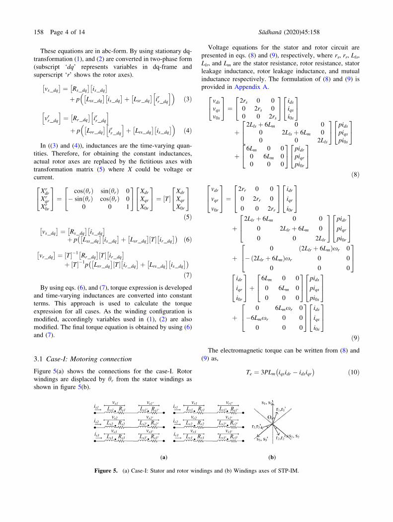
3.1 Case-I: Motoring connection
Figure 5(a) shows the connections for the case-I. Rotor
windings are displaced by hr from the stator windings as
shown in figure 5(b).
Voltage equations for the stator and rotor circuit are
presented in eqs. (8) and (9), respectively, where rs, rr, Lls,
Llr, and Lm are the stator resistance, rotor resistance, stator
leakage inductance, rotor leakage inductance, and mutual
inductance respectively. The formulation of (8) and (9) is
provided in Appendix A.
vdsvqsv0s
24
35 ¼
2rs 0 0
0 2rs 0
0 0 2rs
24
35
idsiqsi0s
24
35
þ2Lls þ 6Lm 0 0
0 2Lls þ 6Lm 0
0 0 2Lls
24
35
pidspiqspi0s
24
35
þ6Lm 0 0
0 6Lm 0
0 0 0
24
35
pidrpiqrpi0r
24
35
ð8Þ
vdr
vqr
v0r
264
375 ¼
2rr 0 0
0 2rr 0
0 0 2rr
264
375
idr
iqr
i0r
264
375
þ2Llr þ 6Lm 0 0
0 2Llr þ 6Lm 0
0 0 2Llr
264
375
pidr
piqr
pi0r
264
375
þ �0 2Llr þ 6Lmð Þxr 0
2Llr þ 6Lmð Þxr 0 0
0 0 0
264
375
idr
iqr
i0r
264
375þ
6Lm 0 0
0 6Lm 0
0 0 0
264
375
pids
piqs
pi0s
264
375
þ0 6Lmxr 0
�6Lmxr 0 0
0 0 0
264
375
ids
iqs
i0s
264
375
ð9ÞThe electromagnetic torque can be written from (8) and
(9) as,
Te ¼ 3PLm iqsidr � idsiqr� � ð10Þ
(a) (b)
. .
. .
. .is3
Rs1Ls1
Rs2Ls2
Rs3Ls3
Rs1'Ls1'
Rs2'Ls2'
Rs3'Ls3'
vs1
vs2
vs1'
vs2'
vs3'
is1
is2vs3
. .
. .
. .ir3
Rr1Lr1
Rr2Lr2
Rr3Lr3
Rr1'Lr1'
Rr2'Lr2'
Rr3'Lr3'
vr1
vr2
vr1'
vr2'
vr3'
ir1
ir2vr3
Figure 5. (a) Case-I: Stator and rotor windings and (b) Windings axes of STP-IM.
158 Page 4 of 14 Sådhanå (2020) 45:158

Assuming in two pole IM, stator carries the balanced
three-phase current with peak Is -and rotor carries the cur-
rent Ir having a phase angle of h with respect to stator
current, then from (10), Te is calculated as 9LmIsIr sin h. Ifthe phase angle between stator and rotor current is 90o, then
maximum electromagnetic torque is obtained. The torque
value is positive constant for the constant stator current as
in (11) and shown in figure 6.
Te ¼ k ðwhere; k ¼ 9LmIsIrÞ ð11ÞHence, rotor rotates in case-I. It is observed from (10) that
for generating torque, product term of both currents should be
in quadrature and one current is from stator, and other is from
rotor. But if stator of IM having single-phase supply as given
in [10, 11] then ids ¼ iqs ¼ 0. Therefore, electromagnetic
torque for single-phase supply is zero and rotor is standstill.
3.2 Case-II: Opposite sense of orientation
In case-II, current enters through dot in one winding and it
leaves through dot in other as shown in figure 7.
Voltage equation for stator (12) and rotor (13), shows
that there is no mutual terms present between stator and
rotor (Appendix B).
vdsvqsv0s
24
35 ¼
2rs 0 0
0 2rs 0
0 0 2rs
24
35
idsiqsi0s
24
35
þ2Lls 0 0
0 2Lls 0
0 0 2Lls
24
35
pidspiqspi0s
24
35 ð12Þ
vdrvqrv0r
24
35 ¼
2rr 0 0
0 2rr 0
0 0 2rr
24
35
idriqri0r
24
35
þ2Llr 0 0
0 2Llr 0
0 0 2Llr
24
35
pidrpiqrpi0r
24
35 ð13Þ
The electromagnetic torque developed in this case is
zero. Therefore,
Te ¼ 0 ð14ÞThis condition confirms that the field developed by one
winding is cancelled by other winding, leading to zero
electromagnetic torque production as presented in figure 8.
3.3 Case-III: Opposite phase-sequence of supply
In case-III, as shown in figure 9, half stator windings are
supplied by opposite phase-sequence of supply. The torque
expression for such cases are developed by formulating two
torque equations, i.e., one for each phase-sequence supply.
For stator-I and rotor-I windings, voltage equations (15),
and (16) are mentioned below (refer to Appendix C):
vds1
vqs1
v0s1
264
375 ¼
rs 0 0
0 rs 0
0 0 rs
264
375
ids1
iqs1
i0s1
264
375þ
Lls þ 3Lm 0 0
0 Lls 0
0 0 Lls
264
375
pids1
piqs1
pi0s1
264
375þ
3Lmcos2 hrð Þ 1:5Lm sin 2hrð Þ 0
1:5Lm sin 2hrð Þ 3Lmsin2 hrð Þ 0
0 0 0
264
375
pidr1
piqr1
pi0r1
264
375þ
�3Lmxr sin 2hrð Þ 3Lmxr cos 2hrð Þ 0
3Lmxr cos 2hrð Þ 3Lmxr sin 2hrð Þ 0
0 0 0
264
375
idr1
iqr1
i0r1
264
375
ð15Þ
Figure 6. Case-I: Electromagnetic torque.
Figure 7. Case-II: Stator and rotor windings.
Figure 8. Case-II: Electromagnetic torque.
Rotor-I Rotor-II
. .
. .
. .
is1
is2
is3
Rs1Ls1
Rs2Ls2
Rs3Ls3
Ls1'
Rs2'Ls2'
Rs3'Ls3'
vs1
vs2
vs3
vs1'
vs3'
vs2'
Rs1' . .. .. .
ir1
ir2
ir3
Rr1Lr1
Rr2Lr2
Rr3Lr3
Lr1'
Rr2'Lr2'
Rr3'Lr3'
vr1
vr2
vr3
vr1'
vr3'
vr2'
Rr1'
Stator-I Stator-II
Figure 9. Case-III: Stator and rotor windings.
Sådhanå (2020) 45:158 Page 5 of 14 158

vdr1
vqr1
v0r1
264
375 ¼
rr 0 0
0 rr 0
0 0 rr
264
375
idr1
iqr1
i0r1
264
375
þLlr þ 3Lmcos
2 hrð Þ 1:5Lmxr sin 2hrð Þ 0
1:5Lmxr sin 2hrð Þ Llr þ 3Lmsin2 hrð Þ 0
0 0 Llr
264
375
pidr1
piqr1
pi0r1
264
375
þ�1:5Lmxr sin 2hrð Þ Llrxr þ 3Lmxrcos
2 hrð Þ 0
�Llrxr � 3Lmxrsin2 hrð Þ 1:5Lmxr sin 2hrð Þ 0
0 0 0
264
375
idr1
iqr1
i0r1
264
375
þ3Lm 0 0
0 0 0
0 0 0
264
375
pids1
piqs1
pi0s1
264
375þ
0 0 0
�3Lmxr 0 0
0 0 0
264
375
ids1
iqs1
i0s1
264
375
ð16ÞThe first torque expression is formed by considering first
half of stator and rotor windings as presented in (17).
Te�I ¼ P=2ð Þ �3Lm sin 2hrð Þids1idr1 þ 3Lm cos 2hrð Þids1iqr1�
þ3Lm cos 2hrð Þiqs1idr1þ 3Lm sin 2hrð Þiqs1iqr1 � 1:5Lm sin 2hrð Þi2dr1þ3Lm cos 2hrð Þidr1iqr1 þ 1:5Lm sin 2hrð Þi2qr1� 3Lmids1iqr1
�
ð17ÞThe second expression is developed by taking other half
of stator and rotor windings. It is observed that final voltage
equations are similar as (15) and (16). Due to opposite
phase-sequence, voltage and current in dq-frame are not
same as of (stator-I and rotor-I). Therefore, for stator-II and
rotor-II, these terms are written with subscript ‘2’. For
stator-II and rotor-II, torque equation shown in (18).
Te�II ¼ P=2ð Þ �3Lm sin 2hrð Þids2idr2 þ 3Lm cos 2hrð Þids2iqr2�
þ3Lm cos 2hrð Þiqs2idr2þ 3Lm sin 2hrð Þiqs2iqr2 � 1:5Lm sin 2hrð Þi2dr2þ3Lm cos 2hrð Þidr2iqr2 þ 1:5Lm sin 2hrð Þi2qr2� 3Lmids2iqr2
�
ð18ÞTe-I gives torque for first half stator windings and Te-II
provides the torque for other half stator windings. Stator-I
and stator-II windings are having different phase-sequence
of supply, therefore (19) shows the relationship between the
dq variables for both the windings.
ids ¼ ids1 ¼ ids2; idr ¼ idr1 ¼ idr2
iqs ¼ iqs1 ¼ �iqs2; iqr ¼ iqr1 ¼ �iqr2
i0s ¼ i0s1 ¼ i0s2; i0r ¼ i0r1 ¼ i0r2
ð19Þ
By adding both torques, final resultant is obtained and
given by (20).
Te ¼ Te�I þ Te�II
Te ¼ 1:5PLm sin 2hrð Þ 2 iqsiqr � idsidr� �þ i2qr � i2dr
� �h i
ð20ÞFrom this expression, it is observed that there is no
multiplication of quadrature current. After assuming bal-
anced sinusoidal current with phase difference of 90o for
stator and rotor of two pole IM, then (20) is converted into
(21).
Te ¼ k1 sin 2xtð Þ � k2 cos 2xtð Þ ð21Þwhere k1 ¼ 9LmIsIr sin 2hrð Þ,k2 ¼ 4:5LmI
2r sin 2hrð Þ
Here hr is constant, therefore double frequency (2xt)component is present in Te. The electromagnetic torque
developed in case-III will oscillate around zero axis with
double frequency oscillations as shown in figure 10.
It is justified from (21), that nature of torque in case-III is
of pulsating nature which is incapable to rotate the rotor. If
hr is made equal to xt by using external force on the rotor
then average value of this torque is non-zero which rotates
the rotor. The magnitude of the pulsating torque could be
reduced by reducing the magnitude of PMF. This can be
obtained by connecting the R-phase windings in opposite
sense of orientation. This case is discussed in next section.
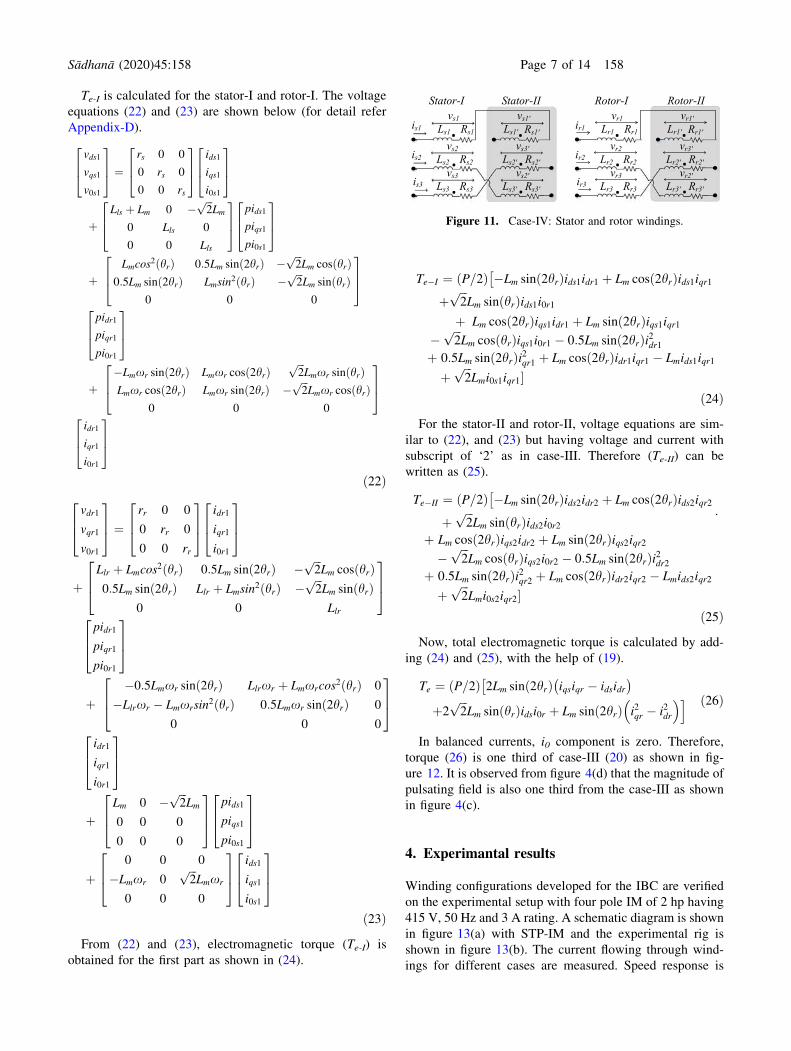
3.4 Case-IV: (Combination of case-II and case-III)
The torque equation for this case is also obtained by using
the same approach as of case-III and winding connection is
shown in figure 11.
Figure 10. Case-III: Electromagnetic torque.
158 Page 6 of 14 Sådhanå (2020) 45:158
Te-I is calculated for the stator-I and rotor-I. The voltage
equations (22) and (23) are shown below (for detail refer
Appendix-D).
vds1
vqs1
v0s1
264
375 ¼
rs 0 0
0 rs 0
0 0 rs
264
375
ids1
iqs1
i0s1
264
375
þLls þ Lm 0 � ffiffiffi
2p
Lm
0 Lls 0
0 0 Lls
264
375
pids1
piqs1
pi0s1
264
375
þLmcos
2 hrð Þ 0:5Lm sin 2hrð Þ � ffiffiffi2
pLm cos hrð Þ
0:5Lm sin 2hrð Þ Lmsin2 hrð Þ � ffiffiffi
2p
Lm sin hrð Þ0 0 0
264
375
pidr1
piqr1
pi0r1
264
375
þ�Lmxr sin 2hrð Þ Lmxr cos 2hrð Þ ffiffiffi
2p
Lmxr sin hrð ÞLmxr cos 2hrð Þ Lmxr sin 2hrð Þ � ffiffiffi
2p
Lmxr cos hrð Þ0 0 0
264
375
idr1
iqr1
i0r1
264
375
ð22Þvdr1
vqr1
v0r1
264
375 ¼
rr 0 0
0 rr 0
0 0 rr
264
375
idr1
iqr1
i0r1
264
375
þLlr þ Lmcos
2 hrð Þ 0:5Lm sin 2hrð Þ � ffiffiffi2
pLm cos hrð Þ
0:5Lm sin 2hrð Þ Llr þ Lmsin2 hrð Þ � ffiffiffi
2p
Lm sin hrð Þ0 0 Llr
264
375
pidr1
piqr1
pi0r1
264
375
þ�0:5Lmxr sin 2hrð Þ Llrxr þ Lmxrcos
2 hrð Þ 0
�Llrxr � Lmxrsin2 hrð Þ 0:5Lmxr sin 2hrð Þ 0
0 0 0
264
375
idr1
iqr1
i0r1
264
375
þLm 0 � ffiffiffi
2p
Lm
0 0 0
0 0 0
264
375
pids1
piqs1
pi0s1
264
375
þ0 0 0
�Lmxr 0ffiffiffi2
pLmxr
0 0 0
264
375
ids1
iqs1
i0s1
264
375
ð23ÞFrom (22) and (23), electromagnetic torque (Te-I) is
obtained for the first part as shown in (24).
Te�I ¼ P=2ð Þ �Lm sin 2hrð Þids1idr1 þ Lm cos 2hrð Þids1iqr1�
þffiffiffi2
pLm sin hrð Þids1i0r1
þ Lm cos 2hrð Þiqs1idr1 þ Lm sin 2hrð Þiqs1iqr1�
ffiffiffi2
pLm cos hrð Þiqs1i0r1 � 0:5Lm sin 2hrð Þi2dr1
þ 0:5Lm sin 2hrð Þi2qr1 þ Lm cos 2hrð Þidr1iqr1 � Lmids1iqr1
þffiffiffi2
pLmi0s1iqr1�
ð24ÞFor the stator-II and rotor-II, voltage equations are sim-
ilar to (22), and (23) but having voltage and current with
subscript of ‘2’ as in case-III. Therefore (Te-II) can be
written as (25).
Te�II ¼ P=2ð Þ �Lm sin 2hrð Þids2idr2 þ Lm cos 2hrð Þids2iqr2�
þffiffiffi2
pLm sin hrð Þids2i0r2
:
þ Lm cos 2hrð Þiqs2idr2 þ Lm sin 2hrð Þiqs2iqr2�
ffiffiffi2
pLm cos hrð Þiqs2i0r2 � 0:5Lm sin 2hrð Þi2dr2
þ 0:5Lm sin 2hrð Þi2qr2 þ Lm cos 2hrð Þidr2iqr2 � Lmids2iqr2
þffiffiffi2
pLmi0s2iqr2�
ð25ÞNow, total electromagnetic torque is calculated by add-
ing (24) and (25), with the help of (19).
Te ¼ P=2ð Þ 2Lm sin 2hrð Þ iqsiqr � idsidr� ��
þ2ffiffiffi2
pLm sin hrð Þidsi0r þ Lm sin 2hrð Þ i2qr � i2dr
� �i ð26Þ
In balanced currents, i0 component is zero. Therefore,
torque (26) is one third of case-III (20) as shown in fig-
ure 12. It is observed from figure 4(d) that the magnitude of
pulsating field is also one third from the case-III as shown
in figure 4(c).
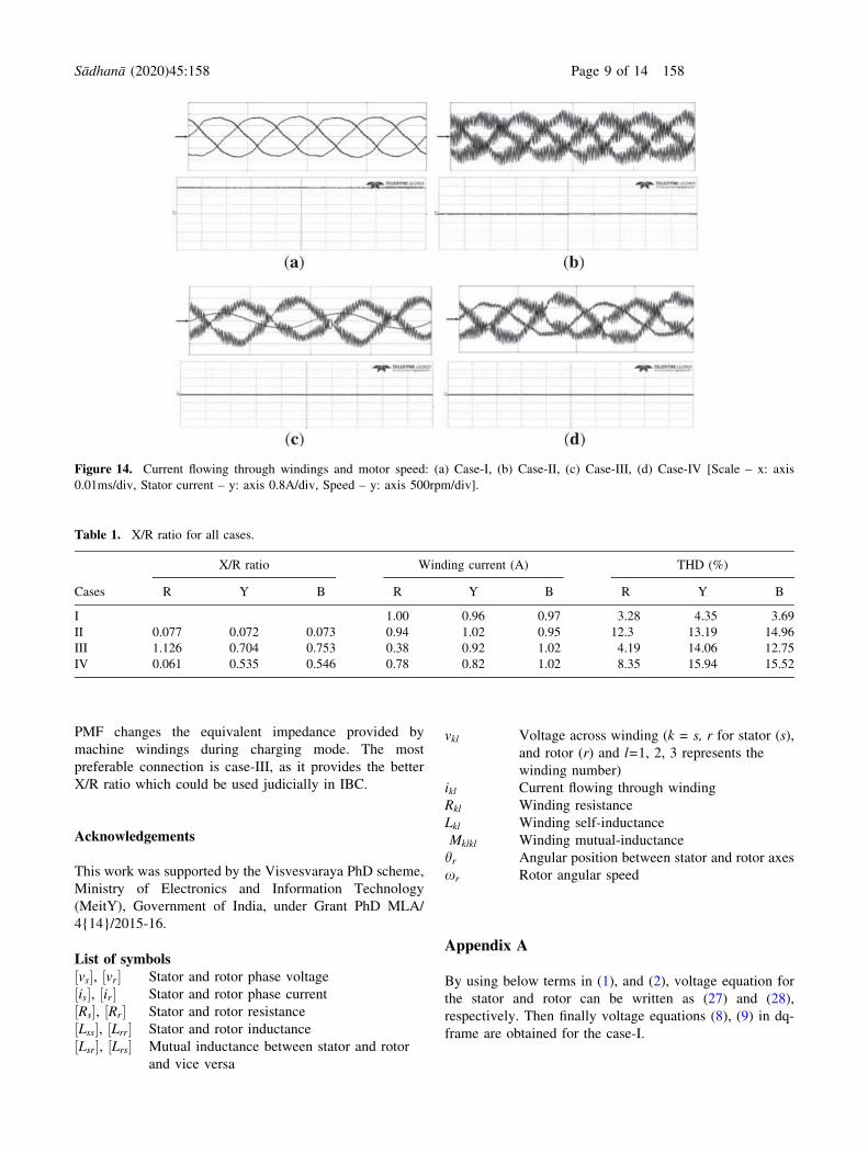
4. Experimantal results
Winding configurations developed for the IBC are verified
on the experimental setup with four pole IM of 2 hp having
415 V, 50 Hz and 3 A rating. A schematic diagram is shown
in figure 13(a) with STP-IM and the experimental rig is
shown in figure 13(b). The current flowing through wind-
ings for different cases are measured. Speed response is
Figure 11. Case-IV: Stator and rotor windings.
Sådhanå (2020) 45:158 Page 7 of 14 158

observed by using EN 801-1500 shaft encoder and captured
with onboard DAC of Texas Instruments digital signal
processor (TMS320F28377S). The voltage equations (in
abc-form) written for the respective cases, provides the
equivalent inductance values which can be used for filtering
purpose.
In case-I, inductance provided by windings is high and
balanced as seen from (27). Therefore, current has a bal-
anced nature with low total harmonic distortion (THD)
however the rotor of machine rotates. Hence it is not used
for filtering operation. Current and speed waveform for
case-I is shown in figure 14(a). As observed from voltage
equation (29) only leakage inductance is responsible for
filtering operation in case-II winding connections. These
inductances are balanced in all phases but have low values,
therefore balanced current with high THD is observed. The
case-II connection do not generate electromagnetic torque
in rotor, therefore, speed of rotor is zero as shown in
figure 14(b).
Winding impedances of case-III are unbalanced as
noticed in voltage equation (31). Y-phase and B-phase have
same but lower value of inductance than R-phase. Winding
current and speed of rotor for case-III is shown in fig-
ure 14(c). It observed that rotor is standstill, with R-phase
having lower current with lower THD. This unbalance in
winding current is generated by the presence of PMF in
machine. For the case-IV, magnitude of PMF developed
along R-phase is reduced by connecting the R-phase
winding with opposite sense of orientation. As the magni-
tude of PMF is reduced, the unbalance in winding current is
also reduced and rotor is also standstill as shown in fig-
ure 14(d). Table 1 shows the X/R ratio of the winding.
These values are obtained by performing the block rotor
test on the machine. The value of winding current with its
THD in respective phases observed during the experimen-
tation are also shown in table 1. Case-I have balanced
current with low THD, but rotor is not stationary. Case-II
also shows the balanced current with electromagnetic tor-
que equal to zero but have high THD. Case-III have
unbalanced currents due to PMF effect. In the case-IV,
PMF effect is reduced therefore the unbalance in winding
current is also reduced. Among all cases in which rotor is
stationary, case-III has high X/R ratio. However, THD in
the grid current is high because of the unbalanced nature of
the filter impedances [29]. The grid current THD and power
factor correction due to this unbalance can be reduced by
using various algorithms, as explained in [28, 29].
5. Conclusion
In this paper, STP-IM as a grid interfacing inductor
between the grid and converter is discussed. Various
winding configurations are proposed that could be used for
IBC. A mathematical investigation is presented which
indicates the nature of torque produced in the winding
connections. Derived torque equations provide the mathe-
matical proof for the stand stillness of the rotor. In those
connections where PMF is present, pulsating torque is
observed which is also incapable to rotate the rotor. Hence
mechanical braking is not required. As the magnitude of
PMF is reduced, the pulsation in electromagnetic torque is
also reduced. The presented experimental results for
winding current and speed of the machine for all developed
cases verifies the numerical investigation. The presence of
Figure 12. Case-IV: Electromagnetic torque.
Figure 13. (a) Schematic diagram and (b) Experimental rig.
158 Page 8 of 14 Sådhanå (2020) 45:158
PMF changes the equivalent impedance provided by
machine windings during charging mode. The most
preferable connection is case-III, as it provides the better
X/R ratio which could be used judicially in IBC.
Acknowledgements
This work was supported by the Visvesvaraya PhD scheme,
Ministry of Electronics and Information Technology
(MeitY), Government of India, under Grant PhD MLA/
4{14}/2015-16.
List of symbolsvs½ �, vr½ � Stator and rotor phase voltage
is½ �, ir½ � Stator and rotor phase current
Rs½ �, Rr½ � Stator and rotor resistance
Lss½ �, Lrr½ � Stator and rotor inductance
Lsr½ �, Lrs½ � Mutual inductance between stator and rotor
and vice versa
vkl Voltage across winding (k = s, r for stator (s),
and rotor (r) and l=1, 2, 3 represents the
winding number)
ikl Current flowing through winding
Rkl Winding resistance
Lkl Winding self-inductance
Mklkl Winding mutual-inductance
hr Angular position between stator and rotor axes
xr Rotor angular speed
Appendix A
By using below terms in (1), and (2), voltage equation for
the stator and rotor can be written as (27) and (28),
respectively. Then finally voltage equations (8), (9) in dq-
frame are obtained for the case-I.
Figure 14. Current flowing through windings and motor speed: (a) Case-I, (b) Case-II, (c) Case-III, (d) Case-IV [Scale – x: axis
0.01ms/div, Stator current – y: axis 0.8A/div, Speed – y: axis 500rpm/div].
Table 1. X/R ratio for all cases.
Cases
X/R ratio Winding current (A) THD (%)
R Y B R Y B R Y B
I 1.00 0.96 0.97 3.28 4.35 3.69
II 0.077 0.072 0.073 0.94 1.02 0.95 12.3 13.19 14.96
III 1.126 0.704 0.753 0.38 0.92 1.02 4.19 14.06 12.75
IV 0.061 0.535 0.546 0.78 0.82 1.02 8.35 15.94 15.52
Sådhanå (2020) 45:158 Page 9 of 14 158

vs½ � ¼vs1 þ vs10
vs2 þ vs20
vs3 þ vs30
24
35; vr½ � ¼
vr1 þ vr10
vr2 þ vr20
vr3 þ vr30
24
35;
is½ � ¼is1is2is3
24
35;
Rs½ � ¼Rs1 þ Rs10 0 0
0 Rs2 þ Rs20 0
0 0 Rs3 þ Rs30
24
35;
ir½ � ¼ir1ir2ir3
24
35;
Rr½ � ¼Rr1 þ Rr10 0 0
0 Rr2 þ Rr20 0
0 0 Rr3 þ Rr30
24
35;
Appendix B
Terms vs½ �, vr½ �, is½ �, ir½ �, Rs½ � and Rr½ � are same as case-I. But
inductance matrices are modified for case-II as shown in
bottom of next page.
Therefore, voltage equation for the case-II can be written
as (29) and (30) for the stator and rotor respectively.
vs½ � ¼2rs 0 0
0 2rs 0
0 0 2rs
264
375
is1
is2
is3
264
375
þ p
2Lls 0 0
0 2Lls 0
0 0 2Lls
264
375
is1
is2
is3
264
375
0B@
1CAþ p
0 0 0
0 0 0
0 0 0
264
375
ir1
ir2
ir3
264
375
0B@
1CA
ð29Þ
Lss½ � ¼Ls1 þMs1s10 þ Ls10 þMs10s1 Ms1s2 þMs1s20 þMs10s2 þMs10s20 Ms1s3 þMs1s30 þMs10s3 þMs10s30
Ms2s1 þMs2s10 þMs20s1 þMs20s10 Ls2 þMs2s20 þ Ls20 þMs20s2 Ms2s3 þMs2s30 þMs20s3 þMs20s30
Ms3s1 þMs3s10 þMs30s1 þMs30s10 Ms3s2 þMs3s20 þMs30s2 þMs30s20 Ls3 þMs3s30 þ Ls30 þMs30s3
24
35
Lsr½ � ¼Ms1r1 þMs1r10 þMs10r1 þMs10r10 Ms1r2 þMs1r20 þMs10r2 þMs10r20 Ms1r3 þMs1r30 þMs10r3 þMs10r30
Ms2r1 þMs2r10 þMs20r1 þMs20r10 Ms2r2 þMs2r20 þMs20r2 þMs20r20 Ms2r3 þMs2r30 þMs20r3 þMs20r30
Ms3r1 þMs3r10 þMs30r1 þMs30r10 Ms3r2 þMs3r20 þMs30r2 þMs30r20 Ms3r3 þMs3r30 þMs30r3 þMs30r30
24
35
Lrr½ � ¼Lr1 þMr1r10 þ Lr10 þMr10r1 Mr1r2 þMr1r20 þMr10r2 þMr10r20 Mr1r3 þMr1r30 þMr10r3 þMr10r30
Mr2r1 þMr2r10 þMr20r1 þMr20r10 Lr2 þMr2r20 þ Lr20 þMr20r2 Mr2r3 þMr2r30 þMr20r3 þMr20r30
Mr3r1 þMr3r10 þMr30r1 þMr30r10 Mr3r2 þMr3r20 þMr30r2 þMr30r20 Lr3 þMr3r30 þ Lr30 þMr30r3
24
35
Lrs½ � ¼Mr1s1 þMr1s10 þMr10s1 þMr10s10 Mr1s2 þMr1s20 þMr10s2 þMr10s20 Mr1s3 þMr1s30 þMr10s3 þMr10s30
Mr2s1 þMr2s10 þMr20s1 þMr20s10 Mr2s2 þMr2s20 þMr20s2 þMr20s20 Mr2s3 þMr2s30 þMr20s3 þMr20s30
Mr3s1 þMr3s10 þMr30s1 þMr30s10 Mr3s2 þMr3s20 þMr30s2 þMr30s20 Mr3s3 þMr3s30 þMr30s3 þMr30s30
24
35
vs½ � ¼2rs 0 0
0 2rs 0
0 0 2rs
264
375
is1
is2
is3
264
375þ p
2Lls þ 4Lm �2Lm �2Lm
�2Lm 2Lls þ 4Lm �2Lm
�2Lm �2Lm 2Lls þ 4Lm
264
375
is1
is2
is3
264
375
0B@
1CA
þ p
4Lm cos hrð Þ 4Lm cos hr þ 2p=3
� �4Lm cos hr þ 4p=3
� �
4Lm cos hr þ 4p=3
� �4Lm cos hrð Þ 4Lm cos hr þ 2p=3
� �
4Lm cos hr þ 2p=3
� �4Lm cos hr þ 4p=3
� �4Lm cos hrð Þ
266664
377775
ir1
ir2
ir3
264
375
0BBBB@
1CCCCA
ð27Þ
vr½ � ¼2rr 0 0
0 2rr 0
0 0 2rr
264
375
ir1
ir2
ir3
264
375þ p
2Llr þ 4Lm �2Lm �2Lm
�2Lm 2Llr þ 4Lm �2Lm
�2Lm �2Lm 2Llr þ 4Lm
264
375
ir1
ir2
ir3
264
375
0B@
1CA
þ p
4Lm cos �hrð Þ 4Lm cos �hr þ 2p=3
� �4Lm cos �hr þ 4p=3
� �
4Lm cos �hr þ 4p=3
� �4Lm cos �hrð Þ 4Lm cos �hr þ 2p=3
� �
4Lm cos �hr þ 2p=3
� �4Lm cos �hr þ 4p=3
� �4Lm cos �hrð Þ
266664
377775
is1
is2
is3
264
375
0BBBB@
1CCCCA
ð28Þ
158 Page 10 of 14 Sådhanå (2020) 45:158

vr½ � ¼2rr 0 0
0 2rr 0
0 0 2rr
24
35
ir1ir2ir3
24
35
þ p
2Llr 0 0
0 2Llr 0
0 0 2Llr
24
35
ir1ir2ir3
24
35
0@
1A
þ p
0 0 0
0 0 0
0 0 0
24
35
is1is2is3
24
35
0@
1A ð30Þ
Transform (29), (30) to stationary dq-frame with ficti-
tious rotor axes gives (12), (13).
Appendix C
In case-III, stator-I and rotor-I windings, terms for voltage
equations (1), and (2) are mentioned below:
vs½ � ¼vs1vs2vs3
24
35; vr½ � ¼
vr1vr2vr3
24
35; is½ � ¼
is1is2is3
24
35;
ir½ � ¼ir1ir2ir3
24
35;
Rs½ � ¼Rs1 0 0
0 Rs2 0
0 0 Rs3
24
35; Rr½ � ¼
Rr1 0 0
0 Rr2 0
0 0 Rr3
24
35;
Lss½ � ¼Ls1 þMs1s10 Ms1s2 þMs1s30 Ms1s3 þMs1s20
Ms2s1 þMs2s10 Ls2 þMs2s30 Ms2s3 þMs2s20
Ms3s1 þMs3s10 Ms3s2 þMs3s30 Ls3 þMs3s20
24
35
Lsr½ � ¼Ms1r1 þMs1r10 Ms1r2 þMs1r30 Ms1r3 þMs1r20
Ms2r1 þMs2r10 Ms2r2 þMs2r30 Ms2r3 þMs2r20
Ms3r1 þMs3r10 Ms3r2 þMs3r30 Ms3r3 þMs3r20
24
35
Lrr½ � ¼Lr1 þMr1r10 Mr1r2 þMr1r30 Mr1r3 þMr1r20
Mr2r1 þMr2r10 Lr2 þMr2r30 Mr2r3 þMr2r20
Mr3r1 þMr3r10 Mr3r2 þMr3r30 Lr3 þMr3r20
24
35
Lrs½ � ¼Mr1s1 þMr1s10 Mr1s2 þMr1s30 Mr1s3 þMr1s20
Mr2s1 þMr2s10 Mr2s2 þMr2s30 Mr2s3 þMr2s20
Mr3s1 þMr3s10 Mr3s2 þMr3s30 Mr3s3 þMr3s20
24
35
Hence, equation for stator voltage (31) and for rotor
voltage (32) is obtained. By transform to stationary dq-
frame (15) and (16) will be obtained.
For stator-II and rotor-II, voltage equations are devel-
oped. Here supply phase-sequence is reversed, therefore
terms are changed to following:
vs½ � ¼vs10
vs30
vs20
24
35; vr½ � ¼
vr10
vr30
vr20
24
35; is½ � ¼
is1is3is2
24
35;
ir½ � ¼ir1ir3ir2
24
35;
Rs½ � ¼Rs10 0 0
0 Rs20 0
0 0 Rs30
24
35; Rr½ � ¼
Rr10 0 0
0 Rr20 0
0 0 Rr30
24
35;
Lss½ � ¼Ls10 þMs10s1 Ms10s20 þMs10s3 Ms10s30 þMs10s2
Ms20s10 þMs20s1 Ls20 þMs20s3 Ms20s30 þMs20s2Ms30s10 þMs30s1 Ms30s20 þMs30s3 Ls30 þMs30s2
24
35
Lsr½ � ¼Ms10r10 þMs10r1 Ms10r20 þMs10r3 Ms10r30 þMs10r2Ms20r10 þMs20r1 Ms20r20 þMs20r3 Ms20r30 þMs20r2Ms30r10 þMs30r1 Ms30r20 þMs30r3 Ms30r30 þMs30r2
24
35
Lrr½ � ¼Lr10 þMr10r1 Mr10r20 þMr10r3 Mr10r30 þMr10r2
Mr20r10 þMr20r1 Lr20 þMr20r3 Mr20r30 þMr20r2Mr30r10 þMr30r1 Mr30r20 þMr30r3 Lr30 þMr30r2
24
35
Lrs½ � ¼Mr10s10 þMr10s1 Mr10s20 þMr10s3 Mr10s30 þMr10s2Mr20s10 þMr20s1 Mr20s20 þMr20s3 Mr20s30 þMr20s2Mr30s10 þMr30s1 Mr30s20 þMr30s3 Mr30s30 þMr30s2
24
35
Lss½ � ¼Ls1 �Ms1s10 þ Ls10 �Ms10s1 Ms1s2 �Ms1s20 �Ms10s2 þMs10s20 Ms1s3 �Ms1s30 �Ms10s3 þMs10s30
Ms2s1 �Ms2s10 �Ms20s1 þMs20s10 Ls2 �Ms2s20 þ Ls20 �Ms20s2 Ms2s3 �Ms2s30 �Ms20s3 þMs20s30
Ms3s1 �Ms3s10 �Ms30s1 þMs30s10 Ms3s2 �Ms3s20 �Ms30s2 þMs30s20 Ls3 �Ms3s30 þ Ls30 �Ms30s3
24
35
Lsr½ � ¼Ms1r1 �Ms1r10 �Ms10r1 þMs10r10 Ms1r2 �Ms1r20 �Ms10r2 þMs10r20 Ms1r3 �Ms1r30 �Ms10r3 þMs10r30
Ms2r1 �Ms2r10 �Ms20r1 þMs20r10 Ms2r2 �Ms2r20 �Ms20r2 þMs20r20 Ms2r3 �Ms2r30 �Ms20r3 þMs20r30
Ms3r1 �Ms3r10 �Ms30r1 þMs30r10 Ms3r2 �Ms3r20 �Ms30r2 þMs30r20 Ms3r3 �Ms3r30 �Ms30r3 þMs30r30
24
35
Lrr½ � ¼Lr1 �Mr1r10 þ Lr10 �Mr10r1 Mr1r2 �Mr1r20 �Mr10r2 þMr10r20 Mr1r3 �Mr1r30 �Mr10r3 þMr10r30
Mr2r1 �Mr2r10 �Mr20r1 þMr20r10 Lr2 �Mr2r20 þ Lr20 �Mr20r2 Mr2r3 �Mr2r30 �Mr20r3 þMr20r30
Mr3r1 �Mr3r10 �Mr30r1 þMr30r10 Mr3r2 �Mr3r20 �Mr30r2 þMr30r20 Lr3 �Mr3r30 þ Lr30 �Mr30r3
24
35
Sådhanå (2020) 45:158 Page 11 of 14 158

Lrs½ � ¼Mr1s1 �Mr1s10 �Mr10s1 þMr10s10 Mr1s2 �Mr1s20 �Mr10s2 þMr10s20 Mr1s3 �Mr1s30 �Mr10s3 þMr10s30
Mr2s1 �Mr2s10 �Mr20s1 þMr20s10 Mr2s2 �Mr2s20 �Mr20s2 þMr20s20 Mr2s3 �Mr2s30 �Mr20s3 þMr20s30
Mr3s1 �Mr3s10 �Mr30s1 þMr30s10 Mr3s2 �Mr3s20 �Mr30s2 þMr30s20 Mr3s3 �Mr3s30 �Mr30s3 þMr30s30
24
35
Appendix D
From the following values for case-IV, voltage equation for
stator-I and rotor-I is given by (22) and (23) respectively, in
stationary dq-frame.
vs½ � ¼vs1vs2vs3
24
35; vr½ � ¼
vr1vr2vr3
24
35; is½ � ¼
is1is2is3
24
35;
ir½ � ¼ir1ir2ir3
24
35;
Rs½ � ¼Rs1 0 0
0 Rs2 0
0 0 Rs3
24
35; Rr½ � ¼
Rr1 0 0
0 Rr2 0
0 0 Rr3
24
35
Lss½ � ¼Ls1 �Ms1s10 Ms1s2 þMs1s30 Ms1s3 þMs1s20
Ms2s1 �Ms2s10 Ls2 þMs2s30 Ms2s3 þMs2s20
Ms3s1 �Ms3s10 Ms3s2 þMs3s30 Ls3 þMs3s20
24
35
Lsr½ � ¼Ms1r1 �Ms1r10 Ms1r2 þMs1r30 Ms1r3 þMs1r20
Ms2r1 �Ms2r10 Ms2r2 þMs2r30 Ms2r3 þMs2r20
Ms3r1 �Ms3r10 Ms3r2 þMs3r30 Ms3r3 þMs3r20
24
35
Lrr½ � ¼Lr1 �Mr1r10 Mr1r2 þMr1r30 Mr1r3 þMr1r20
Mr2r1 �Mr2r10 Lr2 þMr2r30 Mr2r3 þMr2r20
Mr3r1 �Mr3r10 Mr3r2 þMr3r30 Lr3 þMr3r20
24
35
Lrs½ � ¼Mr1s1 �Mr1s10 Mr1s2 þMr1s30 Mr1s3 þMr1s20
Mr2s1 �Mr2s10 Mr2s2 þMr2s30 Mr2s3 þMr2s20
Mr3s1 �Mr3s10 Mr3s2 þMr3s30 Mr3s3 þMr3s20
24
35
Similarly, equations are also developed for stator-II and
rotor-II by using the following variables. Here, current
flowing in the second R-phase winding is in opposite
direction. Therefore, is1 and ir1 currents are replaced by –is1and –ir1 respectively.
vs½ � ¼vs10
vs30
vs20
24
35; vr½ � ¼
vr10
vr30
vr20
24
35; is½ � ¼
�is1is3is2
24
35;
ir½ � ¼�ir1ir3ir2
24
35;
Rs½ � ¼Rs10 0 0
0 Rs20 0
0 0 Rs30
24
35; Rr½ � ¼
Rr10 0 0
0 Rr20 0
0 0 Rr30
24
35;
Lss½ � ¼Ls10 �Ms10s1 �Ms10s20 �Ms10s3 �Ms10s30 �Ms10s2
�Ms20s10 þMs20s1 Ls20 þMs20s3 Ms20s30 þMs20s2�Ms30s10 þMs30s1 Ms30s20 þMs30s3 Ls30 þMs30s2
24
35
Lsr½ � ¼Ms10r10 �Ms10r1 �Ms10r20 �Ms10r3 �Ms10r30 �Ms10r2�Ms20r10 þMs20r1 Ms20r20 þMs20r3 Ms20r30 þMs20r2�Ms30r10 þMs30r1 Ms30r20 þMs30r3 Ms30r30 þMs30r2
24
35
Lrr½ � ¼Lr10 �Mr10r1 �Mr10r20 �Mr10r3 �Mr10r30 �Mr10r2
�Mr20r10 þMr20r1 Lr20 þMr20r3 Mr20r30 þMr20r2�Mr30r10 þMr30r1 Mr30r20 þMr30r3 Lr30 þMr30r2
24
35
Lrs½ � ¼Mr10s10 �Mr10s1 �Mr10s20 �Mr10s3 �Mr10s30 �Mr10s2�Mr20s10 þMr20s1 Mr20s20 þMr20s3 Mr20s30 þMr20s2�Mr30s10 þMr30s1 Mr30s20 þMr30s3 Mr30s30 þMr30s2
24
35
vs1
vs2
vs3
264
375 ¼
rs 0 0
0 rs 0
0 0 rs
264
375
is1
is2
is3
264
375
þ p
Lls þ 2Lm �Lm �Lm
�Lm Lls þ 0:5Lm 0:5Lm
�Lm 0:5Lm Lls þ 0:5Lm
264
375
is1
is2
is3
264
375
0B@
1CA
þ p Lm Z1½ �ir1
ir2
ir3
264
375
0B@
1CA
ð31Þ
Z1 ¼2 cos hrð Þ cos hr þ 2p=3
� �þ cos hr þ 4p=3
� �cos hr þ 4p=3
� �þ cos hr þ 2p=3
� �
2 cos hr þ 4p=3
� �cos hrð Þ þ cos hr þ 2p=3
� �cos hr þ 2p=3
� �þ cos hrð Þ
2 cos hr þ 2p=3
� �cos hr þ 4p=3
� �þ cos hrð Þ cos hrð Þ þ cos hr þ 4p=3
� �
26664
37775
158 Page 12 of 14 Sådhanå (2020) 45:158
vr1
vr2
vr3
264
375 ¼
rr 0 0
0 rr 0
0 0 rr
264
375
ir1
ir2
ir3
264
375
þ p
Llr þ 2Lm �Lm �Lm
�Lm Llr þ 0:5Lm 0:5Lm
�Lm 0:5Lm Llr þ 0:5Lm
264
375
ir1
ir2
ir3
264
375
0B@
1CA
þ p Lm Z2½ �is1
is2
is3
264
375
0B@
1CA
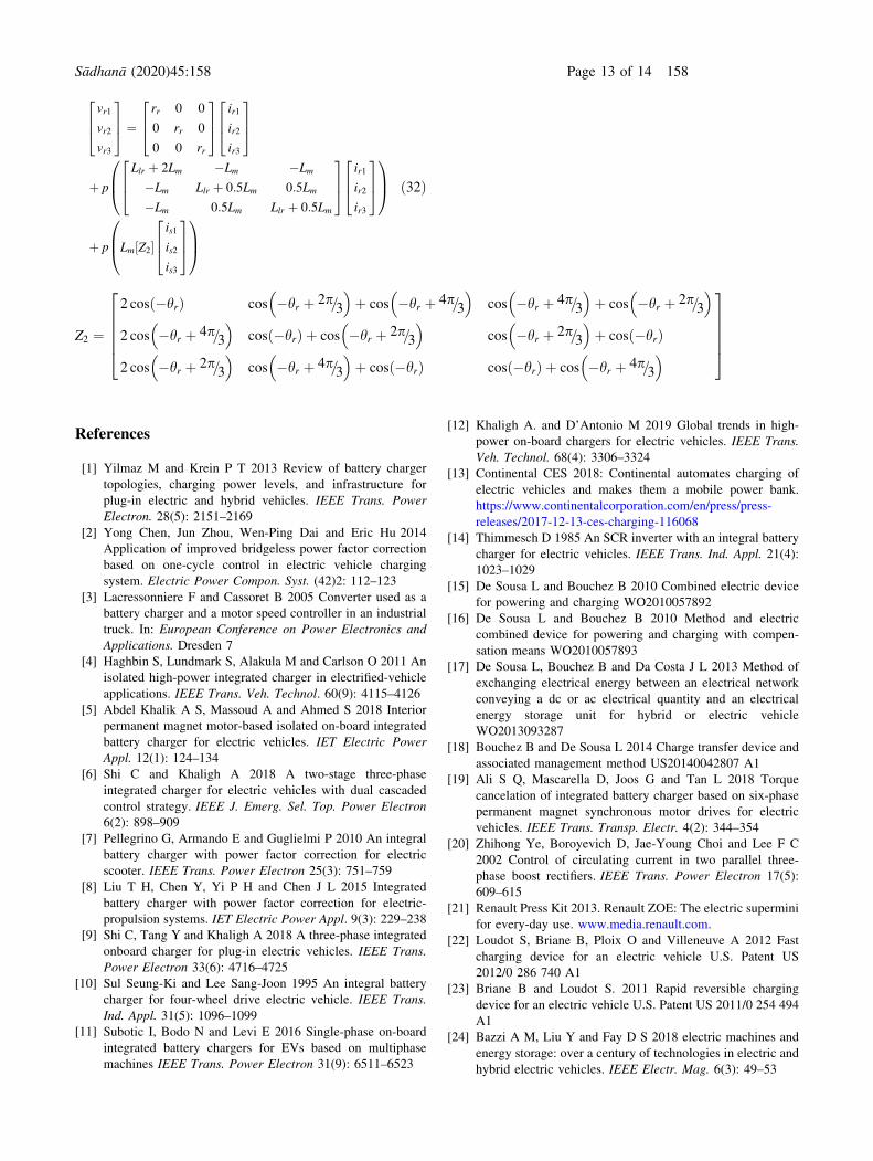
ð32Þ
Z2 ¼
2 cos �hrð Þ cos �hr þ 2p=3
� �þ cos �hr þ 4p=3
� �cos �hr þ 4p=3
� �þ cos �hr þ 2p=3
� �
2 cos �hr þ 4p=3
� �cos �hrð Þ þ cos �hr þ 2p=3
� �cos �hr þ 2p=3
� �þ cos �hrð Þ
2 cos �hr þ 2p=3
� �cos �hr þ 4p=3
� �þ cos �hrð Þ cos �hrð Þ þ cos �hr þ 4p=3
� �
266664
377775
References
[1] Yilmaz M and Krein P T 2013 Review of battery charger
topologies, charging power levels, and infrastructure for
plug-in electric and hybrid vehicles. IEEE Trans. Power
Electron. 28(5): 2151–2169
[2] Yong Chen, Jun Zhou, Wen-Ping Dai and Eric Hu 2014
Application of improved bridgeless power factor correction
based on one-cycle control in electric vehicle charging
system. Electric Power Compon. Syst. (42)2: 112–123
[3] Lacressonniere F and Cassoret B 2005 Converter used as a
battery charger and a motor speed controller in an industrial
truck. In: European Conference on Power Electronics and
Applications. Dresden 7
[4] Haghbin S, Lundmark S, Alakula M and Carlson O 2011 An
isolated high-power integrated charger in electrified-vehicle
applications. IEEE Trans. Veh. Technol. 60(9): 4115–4126
[5] Abdel Khalik A S, Massoud A and Ahmed S 2018 Interior
permanent magnet motor-based isolated on-board integrated
battery charger for electric vehicles. IET Electric Power
Appl. 12(1): 124–134
[6] Shi C and Khaligh A 2018 A two-stage three-phase
integrated charger for electric vehicles with dual cascaded
control strategy. IEEE J. Emerg. Sel. Top. Power Electron
6(2): 898–909
[7] Pellegrino G, Armando E and Guglielmi P 2010 An integral
battery charger with power factor correction for electric
scooter. IEEE Trans. Power Electron 25(3): 751–759
[8] Liu T H, Chen Y, Yi P H and Chen J L 2015 Integrated
battery charger with power factor correction for electric-
propulsion systems. IET Electric Power Appl. 9(3): 229–238
[9] Shi C, Tang Y and Khaligh A 2018 A three-phase integrated
onboard charger for plug-in electric vehicles. IEEE Trans.
Power Electron 33(6): 4716–4725
[10] Sul Seung-Ki and Lee Sang-Joon 1995 An integral battery
charger for four-wheel drive electric vehicle. IEEE Trans.
Ind. Appl. 31(5): 1096–1099
[11] Subotic I, Bodo N and Levi E 2016 Single-phase on-board
integrated battery chargers for EVs based on multiphase
machines IEEE Trans. Power Electron 31(9): 6511–6523
[12] Khaligh A. and D’Antonio M 2019 Global trends in high-
power on-board chargers for electric vehicles. IEEE Trans.
Veh. Technol. 68(4): 3306–3324
[13] Continental CES 2018: Continental automates charging of
electric vehicles and makes them a mobile power bank.
https://www.continentalcorporation.com/en/press/press-
releases/2017-12-13-ces-charging-116068
[14] Thimmesch D 1985 An SCR inverter with an integral battery
charger for electric vehicles. IEEE Trans. Ind. Appl. 21(4):
1023–1029
[15] De Sousa L and Bouchez B 2010 Combined electric device
for powering and charging WO2010057892
[16] De Sousa L and Bouchez B 2010 Method and electric
combined device for powering and charging with compen-
sation means WO2010057893
[17] De Sousa L, Bouchez B and Da Costa J L 2013 Method of
exchanging electrical energy between an electrical network
conveying a dc or ac electrical quantity and an electrical
energy storage unit for hybrid or electric vehicle
WO2013093287
[18] Bouchez B and De Sousa L 2014 Charge transfer device and
associated management method US20140042807 A1
[19] Ali S Q, Mascarella D, Joos G and Tan L 2018 Torque
cancelation of integrated battery charger based on six-phase
permanent magnet synchronous motor drives for electric
vehicles. IEEE Trans. Transp. Electr. 4(2): 344–354
[20] Zhihong Ye, Boroyevich D, Jae-Young Choi and Lee F C
2002 Control of circulating current in two parallel three-
phase boost rectifiers. IEEE Trans. Power Electron 17(5):
609–615
[21] Renault Press Kit 2013. Renault ZOE: The electric supermini
for every-day use. www.media.renault.com.
[22] Loudot S, Briane B, Ploix O and Villeneuve A 2012 Fast
charging device for an electric vehicle U.S. Patent US
2012/0 286 740 A1
[23] Briane B and Loudot S. 2011 Rapid reversible charging
device for an electric vehicle U.S. Patent US 2011/0 254 494
A1
[24] Bazzi A M, Liu Y and Fay D S 2018 electric machines and
energy storage: over a century of technologies in electric and
hybrid electric vehicles. IEEE Electr. Mag. 6(3): 49–53
Sådhanå (2020) 45:158 Page 13 of 14 158

[25] Lacroix S, Laboure E and Hilairet M 2010 An integrated fast
battery charger for Electric Vehicle. In: IEEE Vehicle Power
and Propulsion Conference, pp. 1–6
[26] Mengatto A and Heerdt J A 2017 Analysis and operation of
an integrated battery charger using the EV traction motor as
filter In: Brazilian Power Electronics Conf. (COBEP) 1-6
[27] Li C, Huang W, Cao R, Bu F and Fan C 2016 An integrated
topology of charger and drive for electric buses. IEEE Trans.
Veh. Technol. 65(6): 4471–4479
[28] Subotic I, Bodo N and Levi E 2017 Integration of six-phase
EV drivetrains into battery charging process with direct grid
connection. IEEE Trans. Energy Convers. 32(3): 1012–1022
[29] Suh Yongsug and Lipo T A 2006 Control scheme in hybrid
synchronous stationary frame for PWM AC/DC converter
under generalized unbalanced operating conditions. IEEE
Trans. Ind. Appl. 42(3): 825–835
158 Page 14 of 14 Sådhanå (2020) 45:158