INVESTIGATING THE CAPABILITIES OF SEL 787 TRANsFORMER PROTECTION RELAY USING LOW … ·...
169
INVESTIGATING THE CAPABILITIES OF SEL 787 TRANSFORMER PROTECTION RELAY USING LOW LEVEL SIMULATORS. Thesis submitted to the School of Engineering and Information Technology, Murdoch University in partial fulfilment of the requirements for the degree of Bachelor of Engineering Tendai Raymond Dube Supervisor: Assoc. Prof. Graeme Cole Co-supervisor: Dr. Gregory Creebin 7/1/2016
Transcript of INVESTIGATING THE CAPABILITIES OF SEL 787 TRANsFORMER PROTECTION RELAY USING LOW … ·...

INVESTIGATING THE CAPABILITIES OF SEL 787 TRANSFORMER
PROTECTION RELAY USING LOW LEVEL SIMULATORS.
Thesis submitted to the School of Engineering and Information Technology, Murdoch
University in partial fulfilment of the requirements for the degree of Bachelor of
Engineering
Tendai Raymond Dube
Supervisor: Assoc. Prof. Graeme Cole Co-supervisor: Dr. Gregory Creebin
7/1/2016

i
STATEMENT OF ORIGINALITY
This thesis is my own original work. To the best of my knowledge, I hereby certify that
the work in this thesis contains no material previously written by another person or
submitted for the award of any other degree in any university. All literature and
information sources derived from unpublished and published work of others has been
acknowledged and indicated in this thesis.
09 /01/2016
SIGNED DATE
ii
Abstract
Protection relays play an integral part in electrical power systems. They monitor and
detect abnormal system conditions and initiate the operation of protective devices like
circuit breakers to take corrective action and restore the power system to its normal
state. Over the years, the technology has evolved from the old electromechanical-based
relays to the new microprocessor-based relays also known as intelligent electronic
devices, such as the SEL 787 transformer protection relay. Correct operation of these
devices is critical as malfunction or incorrect operation might lead to severe damage to
protected equipment and costly power outages. In commissioning, maintenance and
training fields, the correct operation and accuracy verification is determined through
carrying out fault simulations on the relay using different types of test equipment or
simulators. This thesis investigates the capabilities of SEL 787 relay by using low level
fault simulators and setting the foundation for the development of a National
Instrument CompactDaq and LabVIEW fault simulator.
The thesis comprises the following three main parts:

iii
Part 1: SEL 787 Transformer protection relay
In this thesis, research has been carried out on the design and application of the SEL 787
relay in transformer protection. The hardware components and the software platform
used by the relay has been analysed. Investigation of the software tools to facilitate
efficient simulations and hence explore the functionality of the relay has been
conducted.
Part 2: Fault simulators / Test equipment
Focuses on the different types of fault simulators in particular low level simulators like
the SEL RTS system. Simulations where carried out on the SEL 787 relay using the SEL
RTS system. The simulation results were analysed using standards and manufacturer
specifications.
Part 3: LabVIEW CompactDaq Simulator
Involves the proposed design of a low level simulator using the CompactDaq modules
and LabVIEW software. Analysis of the CompactDaq modules was conducted. Tests
were successfully carried out using the CompactDaq system via NI Max test panel on the
SEL 787 protection relay.

iv
Acknowledgements
I would like to express my sincere gratitude to my project supervisor, Associate
Professor Graeme Cole, for his support and guidance throughout my studies at Murdoch
University.
Many thanks for assistance and support to Mr Iafeta “Jeff” Laava, Mr Will Stirling and
Mr John Boulton, technical Officers at Murdoch University, and to my fellow thesis
students.
I would like to thank my late mother Mrs G Dube, umaSibindi for inspiring me to get
started and keep going.
Finally, I would like to thank my dear wife, Bukamu Dube and my son, Jayden Tendai
Dube, for their patience, love and understanding throughout my years of study.

v
Contents
ABSTRACT ............................................................................................................. II
ACKNOWLEDGEMENTS ....................................................................................... IV
LIST OF FIGURES ................................................................................................. XI
LIST OF TABLES .................................................................................................. XV
LIST OF EQUATIONS ........................................................................................... XV
LIST OF ABBREVIATIONS .................................................................................. XVI
CHAPTER 1 .................................................................................. PROJECT INTRODUCTION
1
1.1 BACKGROUND ..................................................................................................... 2
1.2 OBJECTIVES ....................................................................................................... 2
CHAPTER 2 ........................................................................................ PROTECTION SCHEME
4
2.1 PURPOSE ........................................................................................................... 4
2.2 ATTRIBUTES OF A GOOD PROTECTION SCHEME ........................................................ 6
2.3 PROTECTION RELAYS........................................................................................... 8
2.3.1 ELECTROMECHANICAL ........................................................................................................... 8
2.3.2 SOLID STATE .......................................................................................................................... 8
2.3.3 MICROPROCESSOR-BASED RELAYS .......................................................................................... 9

vi
CHAPTER 3 ..................................................PROTECTION RELAY FAULT SIMULATORS
11
3.1 HIGH LEVEL SIMULATORS .................................................................................. 12
3.2 LOW LEVEL SIMULATORS ................................................................................... 13
CHAPTER 4 ..................................................................................... POWER TRANSFORMER
15
4.1 POWER TRANSFORMER CONSTRUCTION ............................................................... 15
4.2 PRINCIPLE OF OPERATION .................................................................................. 16
4.2.1 TRANSFORMER MAGNETISATION CHARACTERISTICS .............................................................. 17
4.3 POWER TRANSFORMER FAULTS ........................................................................... 20
4.3.1 PHASE-TO-PHASE FAULTS: ................................................................................................... 20
4.3.2 CORE FAULTS: ....................................................................................................................... 21
4.3.3 TANK FAULTS: ....................................................................................................................... 21
4.3.4 INTERTURN FAULTS: ............................................................................................................ 22
CHAPTER 5 ................................ SCHWEITZER ENGINEERING LABORATORIES, INC.
24
5.1 SEL ACSELERATOR QUICK SET ........................................................................... 24
5.2 SETTINGS ......................................................................................................... 24
5.2.1 SETTINGS EDITOR ................................................................................................................ 24
5.2.2 GROUP SETTING ................................................................................................................... 26
5.2.3 SETTINGS COMPARE ............................................................................................................. 28
5.3 TERMINAL ........................................................................................................ 29

vii
5.4 HUMAN MACHINE INTERFACE HMI ..................................................................... 29
5.5 SEL LOGIC ....................................................................................................... 29
5.6 EVENT ANALYSIS ............................................................................................... 32
CHAPTER 6 .................................................... SEL 787 PROTECTION RELAY OVERVIEW
34
6.1 HARDWARE ...................................................................................................... 34
6.1.1 I/O CARDS ............................................................................................................................35
6.1.2 FRONT PANEL ....................................................................................................................... 40
6.1.3 WIRING CONFIGURATION ...................................................................................................... 41
CHAPTER 7 ...................................... PROTECTION RELAY STANDARDS AND TESTING
45
7.1 PROTECTION RELAY STANDARDS ......................................................................... 45
7.2 RELAY TESTING AND FAULT SIMULATIONS ........................................................... 46
7.2.1 TYPES OF TESTS .................................................................................................................... 46
7.2.2 TEST EQUIPMENT .................................................................................................................. 47
7.2.3 FAULT DATA ARRANGEMENT ................................................................................................. 48
7.2.4 SEL-4000 ........................................................................................................................... 49
7.2.5 SAFETY................................................................................................................................. 49
7.2.6 SELF-TEST ............................................................................................................................ 50
7.3 SIMULATION METHODOLOGY ............................................................................. 50

viii
CHAPTER 8 ..................................................... SEL 787 PROTECTION RELAY ELEMENTS
53
8.1 CURRENT BASED PROTECTION ELEMENTS ............................................................. 53
8.1.1 PHASE OVERCURRENT PROTECTION ....................................................................................... 57
8.1.2 NEGATIVE PHASE SEQUENCE ................................................................................................ 60
8.1.3 RESIDUAL OVERCURRENT PROTECTION ................................................................................. 62
8.1.4 BREAKER FAILURE PROTECTION ........................................................................................... 64
8.2 DIFFERENTIAL PROTECTION ............................................................................... 66
8.2.1 PRINCIPLE OF OPERATION .................................................................................................... 66
8.2.2 DIFFERENTIAL RELAY CONFIGURATION .................................................................................. 71
8.2.3 DIFFERENTIAL RELAY SETTING .............................................................................................. 73
8.2.4 O87P DIFFERENTIAL ELEMENT ............................................................................................. 74
8.2.5 U87P UNRESTRAINED DIFFERENTIAL ELEMENT ..................................................................... 75
8.2.6 DIFFERENTIAL ELEMENT SLOPE 1 .......................................................................................... 76
8.2.7 DIFFERENTIAL ELEMENT SLOPE 2 .......................................................................................... 79
8.2.8 MAGNETIZATION INRUSH SUPPRESSION ................................................................................. 81
8.2.9 OUT OF ZONE / THROUGH FAULT OPERATION SUPPRESSION .................................................. 82
8.3 RESTRICTED EARTH FAULT PROTECTION .............................................................. 86
8.4 VOLTS/HERTZ ..................................................................................................88
CHAPTER 9 ................................................................................... RESULTS AND ANALYSIS
89
9.1 INSTANTANEOUS OVERCURRENT ......................................................................... 89

ix
9.2 NEGATIVE SEQUENCE OVERCURRENT ................................................................... 93
9.3 RESIDUAL GROUND OVERCURRENT ..................................................................... 95
9.4 BREAKER FAILURE ............................................................................................ 97
9.5 UNRESTRAINED DIFFERENTIAL ELEMENT ........................................................... 100
9.6 RESTRAINED DIFFERENTIAL ............................................................................. 102
9.7 SLOPE 1 RESTRAINED DIFFERENTIAL ELEMENT ................................................... 104
9.8 SLOPE 2 RESTRAINED DIFFERENTIAL ELEMENT .................................................. 106
9.9 THROUGH FAULT MONITOR ...............................................................................110
CHAPTER 10 ................................................................ LABVIEW/COMPACTDAQ SYSTEM
115
10.1 COMPACTDAQ ................................................................................................. 115
10.2 NI MAX .......................................................................................................... 117
10.3 SIGNAL OUTPUT MEASUREMENT AND ANALYSIS ................................................... 118
10.4 TESTING RELAY USING NI MAX .......................................................................... 121
CHAPTER 11 ......................................................................................................... CONCLUSION
123
CHAPTER 12 ..................................................................................................... FUTURE WORK
124
CHAPTER 13 ......................................................................................................... REFERENCES
125
x
CHAPTER 14 ......................................................................................................... APPENDICES
129
14.1 APPENDIX A COMPACTDAQ WIRING CONNECTION .............................................. 129
14.2 APPENDIX B ANSI/IEEE DIFFERENTIAL RELAY PROTECTION FUNCTIONS ............. 131
14.3 APPENDIX C SEL 787 RELAY SPECIFICATIONS .................................................... 132
14.4 APPENDIX D OVERCURRENT PROTECTION ELEMENT SIMULATION RESULTS ........... 136
14.5 APPENDIX E NEGATIVE SEQUENCE ELEMENT SIMULATION RESULTS ...................... 140
14.6 APPENDIX G RESIDUAL GROUND (50G) ELEMENT SIMULATION RESULTS .............. 144
14.7 APPENDIX G UNRESTRAINED DIFFERENTIAL PROTECTION (87) ELEMENT SIMULATION
RESULTS ............................................................................................................... 148
xi
List of Figures
Figure 1 Protection scheme components ............................................................................................................. 5
Figure 2 General arrangement of a microprocessor relay .................................................................................. 9
Figure 3 Labvolt high level simulator ................................................................................................................ 12
Figure 4 Low level protection relay simulator set up [8] ................................................................................. 14
Figure 5 Low level protection relay simulator .................................................................................................. 14
Figure 6 Transformer principle of operation [6] .............................................................................................. 17
Figure 7 Transformer magnetisation curve [6] ................................................................................................. 18
Figure 8 Transformer steady state operation [6] .............................................................................................. 19
Figure 9 Transformer transient operation on energisation [6] ...................................................................... 20
Figure 10 Transformer inter-turn fault [6] ...................................................................................................... 23
Figure 11 SEL relay setting editor page ............................................................................................................. 25
Figure 12 SEL 787 terminal window showing setting change ......................................................................... 26
Figure 13 SEL787 Group settings ...................................................................................................................... 27
Figure 14 SEL 787 group setting selection ....................................................................................................... 28
Figure 15 Acselerator Terminal tab [9]............................................................................................................. 29
Figure 16 SEL protection relay logic structure overview [9] ........................................................................... 30
Figure 17 SEL programing language in structured text and decompiled to function block ........................... 31
Figure 18 Terminal Event Report [20] ............................................................................................................. 32
Figure 19 Event Oscillography ...........................................................................................................................33
Figure 20 SEL transformer protection series ................................................................................................... 35
Figure 21 SEL 787 relay I/O cards [9] .............................................................................................................. 36
Figure 22 SEL 787 rear view slots [9] ................................................................................................................ 37
Figure 23 SEL 787 relay at Murdoch University rear view ............................................................................. 38
Figure 24 SEL 787 relay side view information template ............................................................................... 39

xii
Figure 25 SEL 787 front panel [9] .................................................................................................................... 40
Figure 26 Labvolt relay fault simulation setup [13] ......................................................................................... 42
Figure 27 Analog current card .......................................................................................................................... 43
Figure 28 Slot Z Input circuit board ................................................................................................................. 43
Figure 29 Test cable input connection ............................................................................................................. 44
Figure 30 State sequence test template [8] ...................................................................................................... 48
Figure 31 Relay self- test report ........................................................................................................................ 50
Figure 32 Ramp testing ...................................................................................................................................... 52
Figure 33 Inverse time current characteristic equations [9] ........................................................................... 55
Figure 34 Torque control switch logic for overcurrent element [9] ................................................................ 56
Figure 35 SEL 787 Current protection elements [9] ........................................................................................ 57
Figure 36 Fault simulation template ................................................................................................................ 58
Figure 37 Obtaining Sequence quantities in Microprocessor-based relays...................................................... 60
Figure 38 Negative Sequence 50Q [9] ............................................................................................................... 61
Figure 39 Negative Sequence overcurrent settings editor ............................................................................... 61
Figure 40 Simulation template Negative Sequence Element .......................................................................... 62
Figure 41 Residual element 50G [9] ................................................................................................................ 63
Figure 42 Simulation template residual element ............................................................................................ 64
Figure 43 Breaker failure logic [9] ..................................................................................................................... 65
Figure 44 SEL 787 Breaker failure settings editor ........................................................................................... 66
Figure 45 Transformer differential protection [9] ............................................................................................ 67
Figure 46 Operating Characteristic [9] ............................................................................................................ 68
Figure 47 SEL 787 Configuration settings ......................................................................................................... 71
Figure 48 Transformer differential settings...................................................................................................... 73
Figure 49 SEL 787 Differential element logic [24] ........................................................................................... 74
Figure 50 Test template for unrestrained differential element ....................................................................... 76

xiii
Figure 51 Three phase and single phase fault simulation ................................................................................ 79
Figure 52 Slope 2 test card ................................................................................................................................. 81
Figure 53 Harmonic blocking logic [9] ............................................................................................................. 82
Figure 54 In zone and out of zone faults .......................................................................................................... 83
Figure 55 Transformer Time/ Current through fault curves [9] .................................................................... 84
Figure 56 Transformer through fault [9] ......................................................................................................... 85
Figure 57 Test template for through fault simulation ..................................................................................... 86
Figure 58 Restricted earth fault protection [10] ...............................................................................................87
Figure 59 Terminal window showing assertion of overcurrent relay word bit ............................................... 91
Figure 60 SER showing operation of overcurrent element ............................................................................. 92
Figure 61 SER showing time delay for overcurrent ......................................................................................... 92
Figure 62 Terminal window showing assertion of negative sequence relay word bit ................................... 94
Figure 63 Residual overcurrent setting page .................................................................................................... 95
Figure 64 Test template for residual overcurrent ............................................................................................ 96
Figure 65 Terminal window showing assertion of residual ground overcurrent relay word bit ................... 96
Figure 66 SER showing operation of residual overcurrent element ................................................................ 97
Figure 67 Assertion of breaker failure .............................................................................................................. 98
Figure 68 SER indicating operation of the breaker failure element ............................................................... 99
Figure 69 Unrestrained differential element operation ................................................................................. 101
Figure 70 Restrained differential element simulation template and results ................................................ 103
Figure 71 Slope 1 differential element operation results ................................................................................ 104
Figure 72 Restrained element relay word bit activation ................................................................................ 105
Figure 73 SER report for restrained element operation ................................................................................. 105
Figure 74 Slope 1 Differential simulation values in primary values .............................................................. 106
Figure 75 Slope 2 differential element operation results ............................................................................... 107
Figure 76 SER report for restrained element slope 2 operation ................................................................... 108

xiv
Figure 77 Slope 2 Restrained element relay word bit activation .................................................................. 108
Figure 78 Slope 2 Differential simulation values in primary values .............................................................. 109
Figure 79 Through fault simulation metering overview .................................................................................. 111
Figure 80 Differential metering view through fault ....................................................................................... 112
Figure 81 Summary of through fault events .................................................................................................... 113
Figure 82 Through fault relay word bit assertion ........................................................................................... 114
Figure 83 Ethernet CompactDaq chassis [26] ................................................................................................ 115
Figure 84 CompactDaq Modules [26] ............................................................................................................. 116
Figure 85 CompactDaq test setup..................................................................................................................... 117
Figure 86 NI Max test panel ............................................................................................................................ 118
Figure 87 Signal analysis test setup ................................................................................................................. 119
Figure 88 Initial test simulation of output voltages ....................................................................................... 120
Figure 89 Maximum Output Voltages ............................................................................................................. 120
Figure 90 NI Max test platform ....................................................................................................................... 121
Figure 91 Fault simulation using CompactDaq system .................................................................................. 122
xv
List of Tables
Table 1 Phase overcurrent settings .................................................................................................................... 59
List of Equations
Equation 1 Slope restraint value calculation [27] ............................................................................................. 77
Equation 2 Winding 1 test current in per unit [27] .......................................................................................... 77
Equation 3 Winding 2 test current in per unit [27] .......................................................................................... 77
Equation 4 Winding 1 test current in Amps [27] ..............................................................................................78
Equation 5 Winding 2 test current in Amps [27] ..............................................................................................78
Equation 6 Slope 2 test point [27] .................................................................................................................... 80
Equation 7 Slope 2 Winding 1 test current per unit [27] ................................................................................. 80
Equation 8 Slope 2 Winding 2 test current per unit [27] ............................................................................... 80
Equation 9 Slope 2 Winding 1 test current in Amps [27] ................................................................................ 80
Equation 10 Slope 2 Winding 2 test current in Amps [27] .............................................................................. 81
Equation 11 Differential operate current [9] ................................................................................................... 102

xvi
List of Abbreviations
AC - Alternating current
DC Direct current
CT -Current transformer
CVT-Capacitor Voltage Transformers
EMF-Electromotive force
IM – Magnetization Current
INOM-Nominal Current
BIL –Basic Insulation Level
HMI- Human machine interface
PROM, Programmable read only memory
ms, Millisecond
REF-Restricted Earth fault
RTD –Resistance temperature device
SEL –Schweitzer Engineering Laboratories
SER –Sequential Event Report

xvii
VT-Voltage transformer
1
Chapter 1 Project Introduction
The three phase power transformer is the most critical link in power system networks.
The transformer links generation and transmission by stepping up generated voltages
to transmission levels. The transmission voltages are in turn stepped down to
distribution voltage levels [1]. Protection of three phase transformers from fault
currents is done by complex protection systems. One of the key elements of these
systems is the protection relay. Protection relays have the ability to detect fault
currents and initiate the operation of a circuit breaker which interrupts or disconnects
the fault current hence protecting the transformer. Protection relays have developed
over the years from the old electromechanical relays to numeric relays and now the
microprocessor-based relays. The accuracy in metering, monitoring and operation of
the protection relays is of utmost importance in preventing or minimizing damage to
faulty equipment [3].

2
1.1 Background
To determine the accuracy and the functionality of the relays in commissioning,
maintenance and education purposes, various brands of simulators have been
developed . The most popular brands simulators used in industry are Megger,
Omicron and Doble. There are two main types of fault simulators: High level
simulators shown in Figure 3, and low level simulators like the Schweitzer
Engineering Laboratories Relay Testing System (SEL RTS) system shown in Figure 5.
The main difference between the two is the low level simulators bypass the analog
input transformers and lower analog voltage inputs and currents are used in the
simulation process [8]. Previous ENG 454 and thesis students at Murdoch University
have used the Labvolt system, a high level simulator for fault simulation, to
demonstrate the functionality of the SEL relays. Other students had begun the
development of a National Instrument CompactDaq system fault simulation system
with limited success [13]. Following on from some of those previous students’
recommendations, this project will endeavour to continue on with the development of
the system by using a different approach that is described in detail in Chapter 10 of
this thesis [13].
1.2 Objectives
The aim of the project is to gain an in-depth understanding of the capability and
functionality of the SEL 787 transformer protection relay available at Murdoch

3
University through carrying out tests and simulations on the relay using the low level
simulator SEL RTS test system.
Documentation of the research and findings from this report will aid present and
future Industrial Computer Systems students at Murdoch University to have a better
understanding of the transformer protection relay.
A further aim is to advance the understanding of the use of low level simulators in
testing protection relays. Low level simulators, as shown in Figure 5, facilitate fault
simulation in protection by bypassing the protection relay input current and voltage
transformers, hence eliminating the use of large amplifiers.
This project aims to contribute to an ongoing goal of eventually developing a
CompactDaq and LabVIEW protection relay simulator. This will assist engineering
students at Murdoch University and others in understanding the capabilities of the
SEL protection relays as the simulator will provide a faster and more efficient way of
carrying out fault simulations. The relay’s capabilities in protection, monitoring and
metering are thus explored.

4
Chapter 2 Protection Scheme
With the advancement in technology, protection relay systems
have become more complex. The design of the systems and the
core components has evolved to provide more effective and
efficient systems. This chapter looks at the aims and
requirements of a protection system together with the main
components.
2.1 Purpose
A protection scheme is a system of plant and equipment responsible for detecting
abnormal conditions in electrical power systems and initiate the operation of
switchgear to isolate the faulted equipment in the shortest time possible. This reduces
damage on the faulted equipment and stops the effects of the fault from affecting
other functioning parts of the power system [2]. There are two main types of
protection schemes, unit and non-unit protection schemes. Unit schemes of
protection operate only for faults within a clearly demarcated zone. There is no time
coordination required with other protection systems in the power system. On the
other hand, non-unit protection schemes have to be coordinated with other protection
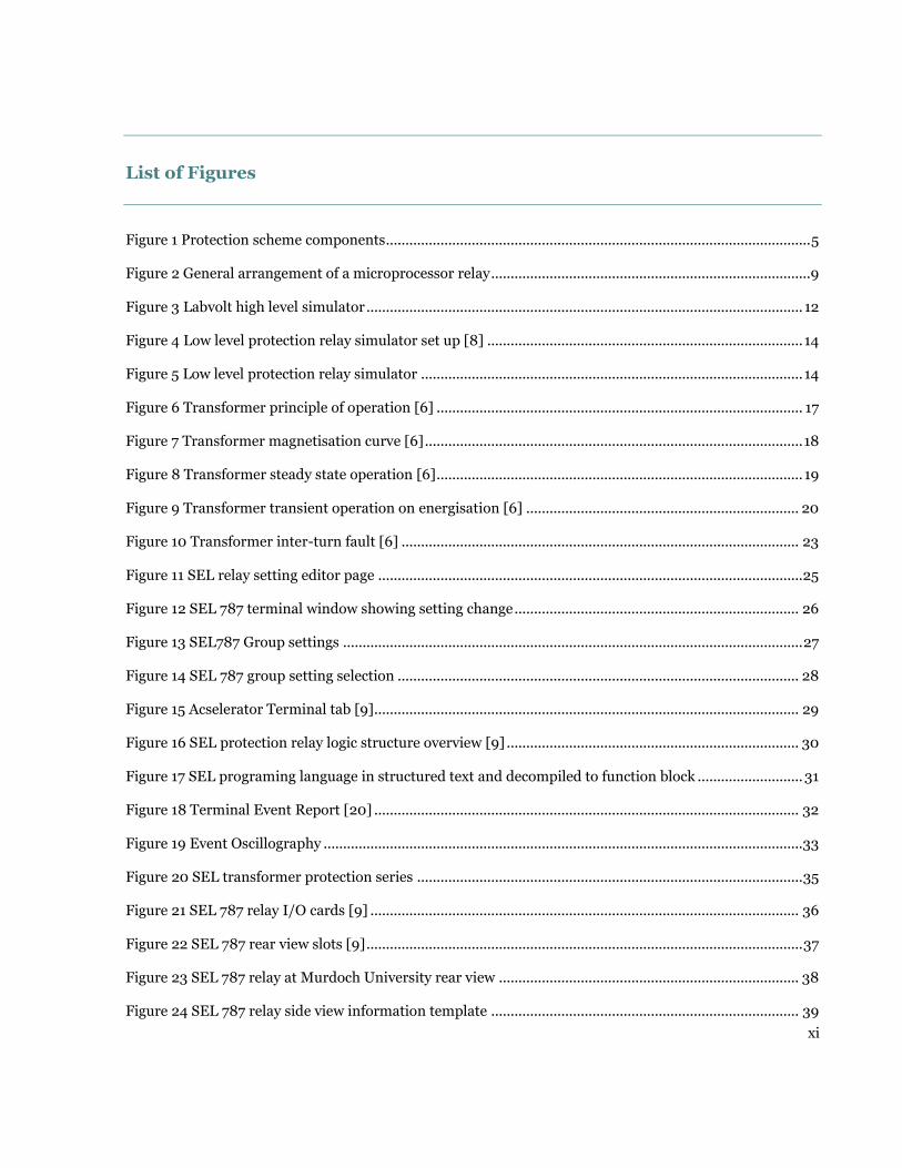
systems in the overall power system. Figure 1 shows the core components of a typical
protection scheme [2].

5
Figure 1 Protection scheme components
The main components of a protection scheme are described below:
Current transformers (CT): these reduce the high values of fault currents which
result under fault conditions to suitable values for protection relay operation.
Thus, the main purpose of the current transformer in protection systems is to
provide currents to the control and protection circuits which are proportional
to the power system currents [4].
Voltage transformers (VT): these step down the system voltage to lower scaled
values to be used in control and protection circuits.
Protected Plant or Equipment
• Transformer • Generator • Motor
Instrument Transformers
• CT • VT • CVT
Protection Relay
•ABB •GE •Schneider •SEL •Siemens
Circuit Breaker

6
Capacitor voltage transformers (CVT) have a capacitance voltage divider which
steps down extra high voltages to low voltages [4].
Protection relay: the device, which is activated by appropriate system
parameters, for example, current and voltage. The relay indicates an abnormal
condition in the power system and initiates the operation of a protection
device, for example, a circuit breaker. There are several manufactures of these
devices including Siemen and SEL, as indicated in Figure 1 above [2].
Circuit breakers: these close and open the electrical circuit under both normal
and fault conditions. The circuit breaker operation under fault conditions is
usually initiated by the protection relay operation [6].
2.2 Attributes of a good protection scheme
Protection systems in most cases do not prevent damage to the faulted equipment
during a fault but rather minimise the damage and the effects of the fault on the entire
electric circuit. The following are the attributes of a good protection system:
Reliability: the protection scheme has to be dependable and operate when
required as per design specifications. Incorrect operation of the protection
scheme may lead to a disastrous situation with damage to plant and
equipment. Reliability of the protection system can be affected by the following
factors: incorrect design, incorrect installation and deterioration of the
protection equipment over time [2].

7
Speedy isolation: to minimise damage to faulted equipment and prevent
system instability, the protection system has to isolate the fault as quickly as
possible. Isolation of the disturbance in the shortest amount of time ensures
continuity of power supply in the functioning parts of the power system. [2]
Sensitivity: this refers to the minimum amount of system quantities (for
example, current) required to activate the protection system when an abnormal
condition arises in the power system. A protection system with a very low
operating current is said to be very sensitive. [2]
Stability: this mainly refers to unit schemes of protection which are only
required to operate for faults occurring within a clearly demarcated region and
not operate for faults outside the protected zone. [2]
Selectivity: this is also referred to as discrimination and refers to the protection
system operating only for the faulty part of the electrical network, isolating it
and leaving the healthy parts of the circuit with supply. [2]
Economical: it is imperative to have appropriate levels of protection for plant
and equipment at an appropriate cost. The degree of protection of a piece of
equipment has to be weighed against the cost of the equipment and the cost of
loss of power supply to the network. The degree of protection usually increases
with the value of equipment being protected as the repair or replacement cost
of the equipment are high. [2]

8
2.3 Protection Relays
2.3.1 Electromechanical
These relays are made of mechanical, electrical and magnetic components and the
majority are of the moveable coil type. The principle of operation of these relays is
based on the establishment of torque, produced by the interaction of magnetic flux,
which is of a magnitude proportional to the value of current and voltage being
measured. These types of protection relays are very reliable and robust, however, they
are less accurate compared to solid state relays and deteriorate over time due to
mechanical moving parts getting worn. [7]
2.3.2 Solid State
Over the years, the development of semiconductors and associated electronic
advances has led to the design of numeric or solid state protection relays. These
relays are more accurate, consume less power, occupy less place on installation, and
are more resistant to vibrations and shock compared to the electromechanical relays.
The downside to the solid state relays is that they require an independent power
supply and are more affected by humidity and temperature. [21]

9
2.3.3 Microprocessor-based Relays
The growing intricacy in modern power networks has necessitated the development of
microprocessor-based relays with sophisticated characteristics. These protection
relays, also called intelligent electronic devices, have high-performance
microprocessors which have the capabilities of performing all the protection functions
done by solid state relays with greater speed and efficiency [7]. Figure 2 shows the
typical general arrangement of microprocessor-based relays.
Figure 2 General arrangement of a microprocessor relay
The main components of a microprocessor-based relay are as follows:

10
Input module: this consists of analog filters, signal conditioner and analog to
digital converters. Signals from the power system are captured and sent to the
microprocessor via this module [7].
Microprocessor: the main purpose of this is to process the protection relay
algorithms. It consists of two memory components: random access memory
responsible for storing information during the processing of protection
algorithms; and read only memory which stores data permanently [7].
Output module: output signals from the microprocessor are conditioned and
sent to the external elements which it controls [7].
Communication module: consists of series and parallel ports which facilitate
connection of protection relays with communication and control systems [7].

11
Chapter 3 Protection relay fault simulators
After manufacture, on installation and during maintenance,
protection relays are tested for correct operation. This chapter
provides an overview of the different types of test equipment
used to verify the correct operation of these relays.
Protection relay test sets or simulators are the pieces of equipment used to measure
the accuracy and demonstrate the full functionality of the relays. The modern day
microprocessor protection relays have multiple functions and require sophisticated
test simulators with hardware and software to comprehensively analyze the operation
of the relay through simulation of real life conditions. There are several types used in
industrial applications, in commissioning the relays in new installations and
maintenance testing in already established installations [4].The commonly used ones
include the Doble F6150, Omicron CMC 365 and Megger MPRT. For educational
purposes, the most popular simulator is the Labvolt system, shown in Figure 3, which
is available at Murdoch University. The fault simulators can be categorized into two
main groups; high level and low level fault simulators.

12
Figure 3 Labvolt high level simulator
3.1 High level simulators
These simulators have the capability of simulating different fault conditions through
hardware and software and monitor the performance of the protection relay. The
hardware components consist of analog outputs, binary outputs and binary inputs
and communication interface for the associated software. The software is used to
control the hardware, monitor and record the protection relay performance during
the simulation. The simulation process mimics real life analog inputs to the relay from
CTs and VTs and monitors the operation of the relay via relay indicators and output
contacts of the relay’s changing state [4].

13
3.2 Low level simulators
The main purpose of these simulators is to supply the protection relay with voltage
and current inputs that resemble fault conditions and monitor how the relay responds
in these situations. The main difference between the two is that the low level
simulators bypass the analog input transformers and lower analog voltage inputs and
currents are used in the simulation process [8]. For example, the SEL RTS low level
simulator provides low voltage AC signals to the protection relay microprocessor via
the relay test interface on the analog input circuit board as shown in Figure 4. The
simulators usually come with the associated software which is used to control,
monitor and record the simulation results. For the SEL RTS simulator, the software is
called SEL 5401. These simulators are less expensive than the high level simulators
[8].

14
Figure 4 Low level protection relay simulator set up [8]
Figure 5 Low level protection relay simulator
`

15
Chapter 4 Power Transformer
Invented towards the end of the nineteenth century the power
transformer has become a vital link in today’s transmission and
distribution systems. This chapter reviews the theory of
principle of operation and the different type of faults which can
occur on transformers.
4.1 Power transformer construction
A power transformer is a static electrical device used to step up or step down voltage.
It consists mainly of two windings: the primary and the secondary windings which are
electrically isolated but magnetically linked through a magnetic core made of
insulated laminations. The insulated laminations are usually made from silicon steel
which increases the magnetic coupling due to its high magnetic permeability
properties.

16
4.2 Principle of operation
A transformer operates on the principles of electromagnetic induction. When an
alternating voltage is applied to the primary windings, self-induction occurs on the
primary windings and the changing alternating current in the primary winding
induces an EMF in the secondary winding, with the process called mutual induction.
The silicon steel core serves to provide a very low reluctance path for the magnetic
flux. The effect of the magnetic flux is to generate a mutually induced EMF in the
secondary winding which is not supplied with the alternating voltage. This is
illustrated in Figure 6 [6].

17
Figure 6 Transformer principle of operation [6]
4.2.1 Transformer magnetisation Characteristics
During normal operation, the transformer follows the typical magnetization curve
shown in Figure 7.

18
Figure 7 Transformer magnetisation curve [6]
Transformers are usually operated close to the knee point of the characteristic to get
the best efficiency. Increasing the terminal voltage leads to the saturation of the core
and excessive magnetization currents being drawn.
Figure 8 shows the relationship between the voltages V, magnetization current IM and
ф magnetic flux under steady state conditions [6].

19
Figure 8 Transformer steady state operation [6]
On energization when the voltage is at zero, the magnetic flux demand is very high
and can be twice the normal magnetic flux. This causes a very high magnetising
current to flow, as illustrated in Figure 9. This high magnetising current (IM) is also
known as the transformer inrush current. The presence of residual flux or remanent
flux can further increase the magnitude of this current on energization [6].

20
Figure 9 Transformer transient operation on energisation [6]
4.3 Power transformer faults
4.3.1 Phase-to-Phase faults:
These faults are rare on transformers and can be caused by both internal and external
conditions. Insulation breakdown due to mechanical stress and overheating can cause
phase to phase and phase to earth faults. External conditions which can lead to phase
to phase faults include overloading, overvoltage and other power system faults.
Internal conditions include ageing insulation and presence of contaminants in
insulating medium [2].

21
4.3.2 Phase-to-Earth faults:
These faults occur when the transformer windings get into contact with earth or any
other conductive material connected to earth. Insulation breakdown due to ageing,
poor workmanship and overheating can cause these type of faults.
4.3.3 Core faults:
The magnetic or iron circuit of the transformer made of insulated laminated silicon
steel has bolts which clamp the laminations together. The bolts are insulated from the
laminations and if this insulation breaks down, high eddy currents may flow which
cause overheating in the transformer. Power system over voltages may lead to high
magnetization currents that produce flux from the highly saturated core, which is
diverted to the clamping bolts. The bolts usually have low flux circulation but the high
flux can result in very high temperatures emanating from the bolts. The high
temperatures cause damage to the insulation leading to the short-circuiting of the
core laminations [6].
4.3.4 Tank faults:
Oil filled transformers are housed in tanks containing insulating oil which completely
covers the windings and the core. The main purpose of the oil is to cool the
transformer; it also acts as an insulating medium. The loss of oil via leaks can lead to

22
overheating of the transformer and insulation reduction. Overheating of the
transformer causes break down of insulation in the winding and results in short
circuit faults [2]
4.3.5 Inter-turn Faults:
Insulation between turns can break down due several factors which include
overheating, mechanical stress from over voltages and ageing of the insulation which
can be made worse by the presence of moisture in the transformer. Figure 10 shows
an inter-turn fault on the secondary side of the transformer. The inter-turn short
circuit will result in high currents in the short- circuited loop. The terminal currents
will be low due to the high transformation ratio between the whole affected winding
and the turns, which are short-circuited [6].

23
Figure 10 Transformer inter-turn fault [6]

24
Chapter 5 Schweitzer Engineering Laboratories, Inc.
Established in 1982, Schweitzer Engineering laboratories SEL is
an organisation based in Washington, United States of America
and specialises in the manufacture of power system protection
relays. This chapter provides an overview of the SEL protection
relay software package and some of its key features used
throughout this project.
5.1 SEL Acselerator Quick set
This software platform tool from SEL is used as the interface between the SEL
protection devices and the user for communication, metering, control, protection and
monitoring purposes. The following section will look at some of the important
features of this software platform [9].
5.2 Settings
5.2.1 Settings Editor
The protection relay settings specific to the device are found in the settings editor. The
settings can be edited according to the protection system requirements. The settings
have a fixed range which when violated an error message comes up and setting box is
highlighted in red as shown in Figure 11.

25
This feature also applies for logic based settings and equations, if an invalid word bit
is entered in the setting box for the logic equation an error message comes up. These
features are useful for identifying any setting errors in conducting simulations.
Figure 11 SEL relay setting editor page
Protection relay setting changes can be tracked or monitored via the terminal window
by typing the sequential event record command (SER). This will give the date and
time when changes to the settings were made as shown in Figure 12 taken during
simulations on the SEL 787 relay [9].

26
Figure 12 SEL 787 terminal window showing setting change
5.2.2 Group setting
The software platform also allows for the flexibility to have more than one group
setting for each device. These settings are configured in groups, as shown in Figure 13,
which was taken from the SEL 787 protection relay at Murdoch University via
Acselerator software. The user is able to configure different settings for different
applications if required; for example, a power utility company might desire to have
different protection settings for different seasons of the year [9].

27
Figure 13 SEL787 Group settings
For testing purposes, having a different group of settings is convienient as changes
can be made to these settings without affecting the original settings [9]. Selection of
the final group settings to be used at a particular time can be done via the setting
group selection tab shown below in Figure 14.

28
Figure 14 SEL 787 group setting selection
5.2.3 Settings compare
This feature allows the user to compare settings between databases. During testing,
the user may need to disenable some of the protection element settings to
accommodate the verification or testing of required protection elements. This feature
affords the user to compare the original settings and the modified settings verify the
changes and update the settings as required. With the setting compare feature,
comparison of settings between different setting groups can be done [9].

29
5.3 Terminal
The terminal window accessed on the tools tab is shown in Figure 15.
Figure 15 Acselerator Terminal tab [9]
The terminal or command window is an interface with the relay using ASCII. This
window was used in the project for the following: relay verification, identification,
communication verification, monitoring, protection element operation verification
and event history analysis [9].
5.4 Human machine Interface HMI
This tool is useful for commissioning and testing and throughout the project duration
it was used to observe metering and target data. Operation of protection elements can
be viewed from this window. The control window of the HMI was used to reset
metering data, clear event history and the sequential event report [9].
5.5 SEL Logic

30
The block diagram shown in Figure 16 shows the sequential interaction of the
protection and programmable logic. SEL logic equations are used to logically integrate
chosen protection relay elements for different control functions. Protection relay
inputs are assigned via the logic equations to suit specific applications [9].
Figure 16 SEL protection relay logic structure overview [9]
Design of the application suited trip, open, close and reclose control logic circuits can
be achieved in programming the logic equations. Using the logic has the benefit of
eliminating the use of external timers and needing counters hard wired, hence saving
time and money. Programming in SEL protection relay is done in two programming
languages. The default language used is structured text.

31
This can be changed to function block language via decompiling, as shown in Figure
17, which was captured from the SEL 787 relay at Murdoch University.
Figure 17 SEL programing language in structured text and decompiled to function block

32
5.6 Event analysis
Event reports and fault data can be viewed in the terminal window by typing the
command EVE or via SEL Acselerator analytical assistant software 5601. In the
terminal window the data is presented in text format as shown in Figure 18 [20]. The
analytical tool on the other hand displays an analog oscillography which the user can
customise.
Figure 18 Terminal Event Report [20]
Figure 19 shows and oscillography for a fault simulation in three states prior the fault,
during the fault and post fault. This was captured during fault simulation on the SEL
787 protection relay housed at Murdoch University. The event reports contain the
following information date and time of the event, fault data in primary values, relay
identifiers. These tools were used throughout the project to verify correct operation of
the relay and analysis of fault simulation results.

33
Figure 19 Event Oscillography
Pre-fault fault post fault

34
Chapter 6 SEL 787 Protection relay overview
Microprocessor based relays offer effective and efficient fault
detection. This chapter looks at the architecture of the SEL 787
transformer and different types of wiring configuration to
facilitate fault simulation.
6.1 Hardware
The SEL-787 protection belongs to a family of SEL transformer protection relays
shown in Figure 20. The SEL transformer protection relays have a rugged design and
are robust. Two-winding and multiple winding transformers can be protected by this
series of relays depending on the application. Apart from the primary function of
protecting the transformer under abnormal conditions the protection relays can be
used for, transformer monitoring, metering and reporting [9].

35
Figure 20 SEL transformer protection series
6.1.1 I/O cards
The SEL 787 protection relay is a two-winding transformer protection relay. The SEL
787 relay full complement has a total of six rear –panel slots labelled A, B, C, D, E and
Z as as shown in Figures 21 and 22. The protection relay specifications for all the
individual slots are detailed in appendix C of this report.The specifications are critical
to ensure correct operation of the relay and avoid damage to it .The nominal operating
volatges of the relay and slot maximum voltage and current ratings are detailed in this
section [9].

36
Figure 21 SEL 787 relay I/O cards [9]
Figure 22 shows typical rear view of the SEL 787 protection relay with all seven card
slots. Slot A is the power supply and input and output card. The inputs and outputs
can be configured to meet specific applications via the logic programming in
Acselerator Quickset. Slot B in the main base communication card. The slot has fibre -
optic, serial and Ethernet ports. An additional communication slot with input and
output contacts can be accommodated in slot D. Slot E is the voltage input card and
also accommodates for the neutral current analog input.

37
The final slot Z is the analog current transformer input slot with the SEL 787
protection relay having option for 1 amp or 5-amp input [9].
Figure 22 SEL 787 rear view slots [9]
Figure 23 shows the actual SEL 787 at Murdoch University which only has the base
cards slots A, B and Z.

38
Figure 23 SEL 787 relay at Murdoch University rear view
The additional digital communication and voltage cards are not available on the SEL
787 transformer protection relay housed at Murdoch University. Investigations were
only undertaken for the protection functions for the available hardware slots, that is,
for the current based elements, such as overcurrent and differential protection. The
following protection functions: restricted earth fault, volts/hertz and RTD-based
protection element could not be investigated due no hardware slot cards being
available. A relay nameplate depicting the available slot cards and the expansion card
is shown in Figure 24 below.
Slot A Power supply and
output contact
Slot B Communication card
Slot Z Current input card

39
Figure 24 SEL 787 relay side view information template

40
6.1.2 Front panel
The SEL 787 protection relay has 16 trip target and status indication light emitting
diodes (LEDs), as shown in Figure 25. These LEDs can be programmed for a specific
application. Factory labels for each protection function can be replaced with custom
made labels to suit the user’s application, as shown in Figure 25 below. The front
panel LCD display is used for displaying measured values and input and output
status. Four pushbuttons that can be programmed for operator control are also
located on the front panel.
Figure 25 SEL 787 front panel [9]

41
6.1.3 Wiring configuration
For current based fault simulations both high and low level testing slot Z of the
protection relay is used. For high level simulations the analog simulation currents are
wired directly on the slot Z terminals.
Carrying out high level fault simulations on protection relays can be tedious and time
consuming with regards to the wiring configuration as illustrated in Figure 26 which
shows the wiring configuration done by previous students at Murdoch university to
carry out fault simulations on the SEL 787 protection relay.

42
Figure 26 Labvolt relay fault simulation setup [13]
For low level fault simulation, the SEL 787 relay has to be configured to cater for this
type of testing The current input card in slot Z, shown in Figure 27, was removed from
the relay and set up for low level testing.
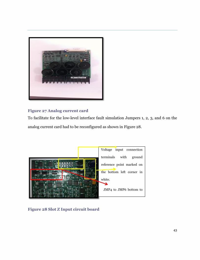
43
Figure 27 Analog current card
To facilitate for the low-level interface fault simulation Jumpers 1, 2, 3, and 6 on the
analog current card had to be reconfigured as shown in Figure 28.
Figure 28 Slot Z Input circuit board
Voltage input connection
terminals with ground
reference point marked on
the bottom left corner in
white.
JMP4 to JMP6 bottom to
top with pins 1 & 2
connected.
JMP 1 to JMP3 with pins 1&
2 connected.

44
Caution in connecting the ribbon test cable to the circuit board was of great
importance to prevent damage to the card. Figure 29 below shows the connection of
the test cable on the circuit board.
The Ribbon cable connected to the SEL-
AMS simulator. The red mark on the
cable connected to the same side to the
white mark.
Figure 29 Test cable input connection

45
Chapter 7 Protection relay standards and testing
To correctly carry out simulations on protection relays is
complex as fault conditions have to be simulated instead of
normal operation conditions. This chapter provides an insight
into the recommended approach to be taken when carrying out
the testing and the related standards. The simulation approach
taken to carrying out tests throughout this project is also
covered in this chapter.
7.1 Protection relay standards
Correct operation of protection relays during fault conditions is critical in preventing
and minimising damage to the protected plant and equipment and ensuring power
system stability. Incorrect operation may lead to protected devices being damaged
and undesirable power outage, hence testing of the relays to manufacturer
specifications is critical [22]. For the SEL 787 protection relay, the manufacturer
specifications with regards to relay element operation accuracy and metering accuracy
are detailed in appendix C of this report. The IEC 60255 standard details the
minimum requirements for the performance of protection relays under both steady
state and dynamic conditions.

46
The different types of simulation methodologies for verifying the accuracy and
performance characteristics of the relays are also specified in this standard [17].
IEEE Standard C37.2-2008 covers and specifies the different elements and
abbreviations for protection relays. The protection relay functions or elements are
referred to by device numbers specified in this standard and letters are often added to
identify a certain application. Table 2 in appendix B of this report details the SEL 787
protection function acronyms and their description, all specified to ANSI and IEEE
standards [18].
7.2 Relay Testing and fault simulations
The guide for power system protection testing, IEEE C37.233/D3 lays out the
different methodologies and procedures to follow in testing protection relays. The
guide specifies the different types of tests and the minimum requirements for the test
equipment used in carrying out the simulations. These guidelines were used as the
foundation in carrying out the fault simulations analysing and verifying the
simulation results [18].
7.2.1 Types of tests
The guide lists the following tests; certification, performance, application,
conformance, commissioning and maintenance are carried out during the life span of

47
a protection relay. For this project conformance and performance tests or simulations
were carried out to verify and explore the capability of the relay.
Conformance tests are done to verify the functionality of a protection element as
expected. The characteristics of the protection element are verified against
specifications. These tests are usually steady state test with the test signals not having
transient and DC components. By contrast, performance tests focus on what is desired
from the protection function under specific network conditions [18].
7.2.2 Test equipment
The IEE c37.233/D3 specifies some of the requirements for simulation equipment as
having software to generate fault sequences. The associated vendor software to
communicate with the protection device and the test equipment has the capability to
record the fault and capture all information associated with the fault. In addition, the
actual miscellaneous test equipment such as test leads and connector jumpers, are all
rated to withstand the required simulation voltages and currents [18].

48
7.2.3 Fault data arrangement
Fault simulations or tests on the protection relays can be done as a single or three
phase injection, depending on the specific requirements. The layout of the fault
simulation can consist of different states and transitions. The states contain the
simulation data, for example pre-fault, fault and the post-fault as shown in Figure 30
[8]. To move from one state to the next, different transitions can be used as desired by
the user, for example, using a timer or user initiated digital input.
Figure 30 State sequence test template [8]

49
7.2.4 SEL-4000
The SEL-4000 system is a low level protection relay simulator and consists of the SEL
AMS shown in Figure 7 and the accompanying software SEL-5401. [8]. This system
was used for the greater part of the project to develop simulation templates and carry
out the testing.
The SEL-AMS consists of twelve analog outputs for voltage and current outputs, and
digital and analog inputs to capture measured times and for the simulation of circuit
breaker status condition. The test system also consists of LEDs on the front panel for
indication of input and output channels, auxiliary DC power supply and a serial
communication port [8].
The SEL-5401 software employs the finite state machine simulation philosophy to
enable simulation using different states as shown in Figure 30. Increment of fault
data in small values in a process called test ramping can be achieved using this
software to determine the minimum fault values which initiate operation of the relay.
Simulation results can be viewed via the simulation window. Both single phase and
three phase fault simulation was carried out [8].
7.2.5 Safety
In order to minimise the risk of injury and damage to equipment and devices, it is
critical to identify the dangers or hazards associated with the specific task to be
undertaken and also to take up actions to reduce or eliminate the hazards. For this
project prior to carrying out the simulations, a job hazard analysis document was

50
completed to identify the hazards and establish the appropriate controls to reduce or
eliminate the hazard.
7.2.6 Self-test
Prior to carrying out the simulations the condition of the protection relay was
assessed by carrying out a self-test and displaying the results in the terminal window.
The command to display the self-test status is STA as shown in Figure 31.
Figure 31 Relay self- test report
7.3 Simulation Methodology
The approach in carrying out the testing or fault simulations was divided into the
following three categories:

51
1. Device under test: This section involved obtaining all the necessary
information and specifications of the protection relay with regards to power
supply, analog AC voltage and current input, frequency and communication
parameters. A thorough understanding of the protection relay elements was
required with regards to their operation characteristics, element setting, relay
model current rating 1 Amp or 5 Amp, the accuracy limits of the secondary
current in steady state and time delay accuracy limits.
2. Low Level simulator: After gathering all the information about the
protection relay to be tested and determining the protection relay elements and
the associated settings, the next step was to configure the simulator or test
equipment to carry out the simulation. For this report, single phase and three
phase fault simulations were carried out. Two main simulation techniques
were employed during the testing process, state sequence and ramping.
Ramping involved incrementing current or phase angle values at a desired rate,
either manually by clicking on the red arrows shown in Figure 32 below, or
automatically by defining the rate of increment. The state sequence method
involved developing static tests with simulation data which is applied to the
device under test. For a defined period of time, transition to the next state is

52
done. If required, as described earlier, there can be a pre-fault, fault and post-
fault states.
Figure 32 Ramp testing
Result monitoring and Analysis: The following tools were used to monitor
operation and analysing the protection results. Protection relay front panel LEDs and
human machine interface device view event report, sequential event report, terminal
which are part of the Acselerator Quickset software. Protection relay operation was
monitored using these tools and the results were compared and analysed against the
manufacturer specifications.
This section of the test
template is used for ramping
the magnitude of the test
parameter voltage, current,
frequency and phase angle.
This magnitude of the test
parameter in this case
current will increase in steps
specified in the increment
section.
53
Chapter 8 SEL 787 Protection relay elements
The SEL 787 transformer protection relay consists of current
and voltage based protection functions. This chapter covers in
detail the operation and the work carried out to explore the
functionality of these protection functions or elements.
8.1 Current based protection elements
The SEL 787 transformer protection relay has the following instantaneous and timed
based current elements: phase overcurrent, residual and negative phase sequence for
both the primary winding and secondary winding of the transformer. The difference
between the instantaneous and timed elements is that an intentional time delay is
introduced on the timed elements for the purposes of achieving protection relay co-
ordination. Protection relay coordination is a process that involves the appropriate
selection of current and time settings of the relay operation to achieve discrimination
in a power system network [9].
The current based elements for SEL 787 protection relay, that is residual, phase and
negative sequence, have inverse time characteristics from five U.S and IEC

54
characteristics. The equations for these characteristics are shown in Figure 33 below
[9].

55
Figure 33 Inverse time current characteristic equations [9]

56
Achieving protection co-ordination between electromechanical relays and
microprocessor-based relays can be challenging, as the electromechanical relays
require a longer period of time to reset. The SEL 787 transformer protection relay
overcomes the issue via the torque control switch, which is enabled by its associated
logic equations as shown in Figure 34 [9].
Figure 34 Torque control switch logic for overcurrent element [9]
Figure 35 shows an illustration of current protection elements of the SEL 787
protection relay: the raw input data from the field is calculated in the relay to
determine if pre-set values have been exceeded for phase, residual and negative phase
sequence elements.

57
Figure 35 SEL 787 Current protection elements [9]
8.1.1 Phase overcurrent protection
This protection element, also denoted by its ANSI code of 50P11P for the
instantaneous element, was initially tested without an intentional time delay and later
tested with a time delay of 5 seconds. The ramping method was used to increase the
currents in incremental steps of 0.01 to determine the minimum amount of current
that causes operation of the relay. The minimum amount of current to operate the
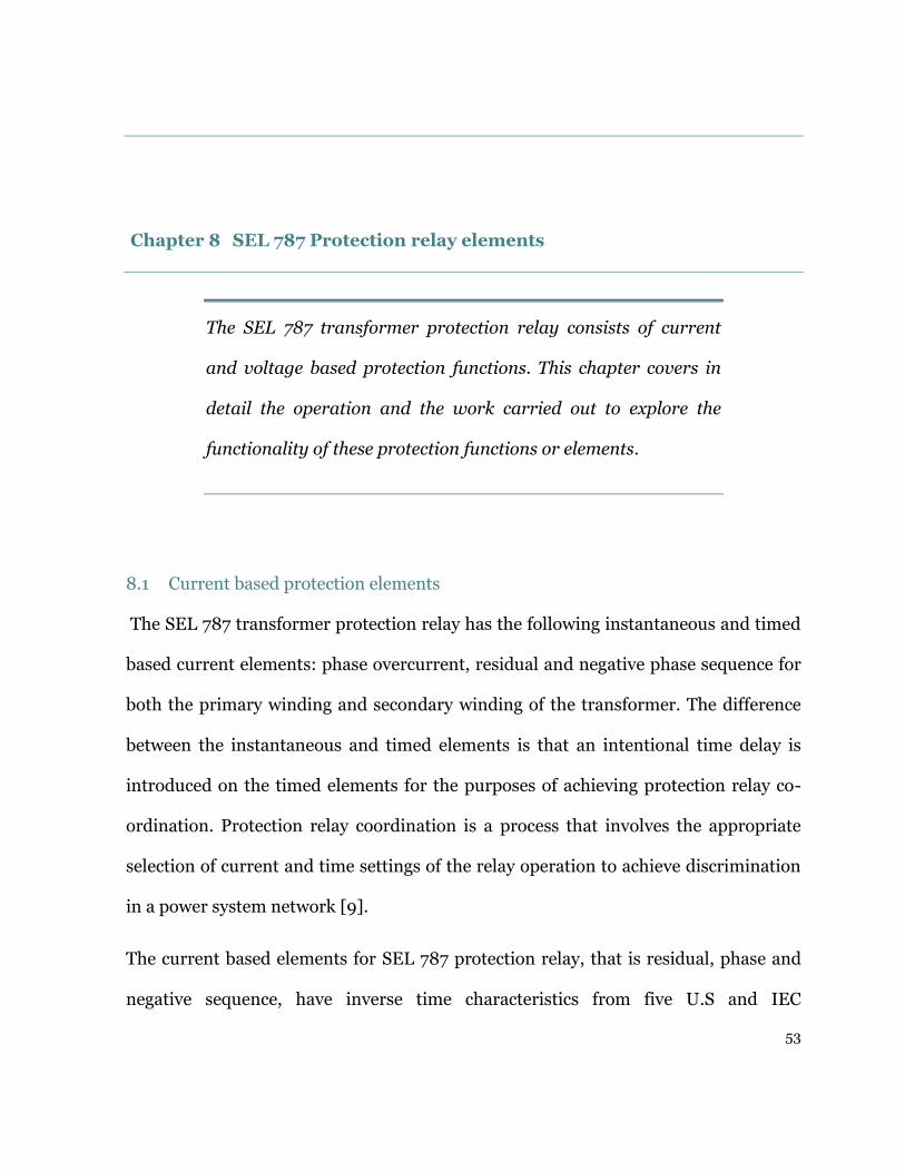
relay was 0.48 Amps as shown in Figure 36, which shows the front panel display for a
single-phase fault simulation on the red phase. Both single phase and three phase
simulations were carried out to investigate operation of this protection element.
58
Figure 36 Fault simulation template
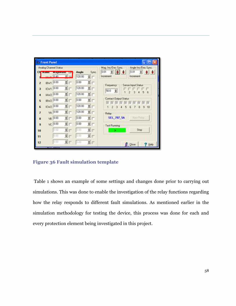
Table 1 shows an example of some settings and changes done prior to carrying out
simulations. This was done to enable the investigation of the relay functions regarding
how the relay responds to different fault simulations. As mentioned earlier in the
simulation methodology for testing the device, this process was done for each and
every protection element being investigated in this project.
59
Table 1 Phase overcurrent settings
Phase overcurrent Test settings
Current setting of 0.5 Amps
instantaneous phase overcurrent.
Time delay for the
instantaneous phase overcurrent
set at 0 seconds.
Phase overcurrent setting change
Time delay setting change from
the initial 0 seconds to 5
seconds.
Sequential Event Report
Adding the instantaneous phase
over current word bit in the
equation event report trigger lists so
that operation of the protection
element can be monitored in
terminal via its word bit.
60
8.1.2 Negative phase sequence
This protection element is mainly used for protection of the power transformer when
there are unbalanced loads and faults in the power system that can cause negative
sequence currents in the transformer. The presence of negative phase sequence
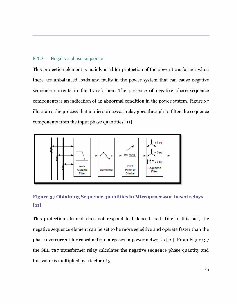
components is an indication of an abnormal condition in the power system. Figure 37
illustrates the process that a microprocessor relay goes through to filter the sequence
components from the input phase quantities [11].
Figure 37 Obtaining Sequence quantities in Microprocessor-based relays
[11]
This protection element does not respond to balanced load. Due to this fact, the
negative sequence element can be set to be more sensitive and operate faster than the
phase overcurrent for coordination purposes in power networks [12]. From Figure 37
the SEL 787 transformer relay calculates the negative sequence phase quantity and
this value is multiplied by a factor of 3.

61
This value is compared to the element predetermined setting value as shown in Figure
39. If the setting value is exceeded, then an output signal is initiated [9].
Figure 38 Negative Sequence 50Q [9]
A three phase fault simulation was carried out to investigate the operation of this
element with the protection setting at 0.3 Amps as shown in Figure 39 below.
Figure 39 Negative Sequence overcurrent settings editor

62
The relay operated as desired for input values of 0.1 Amps, as shown in Figure 40
illustrating the front panel display of the fault simulation currents. The results for the
operation of this element are detailed in the results and analysis section of this report.
Figure 40 Simulation template Negative Sequence Element
8.1.3 Residual overcurrent protection
This protection element is used against earth faults. The relay uses the vector sum of
the currents from the phase current transformer. Under normal conditions the vector
sum of the currents is zero. The residual component only exists under earth fault
conditions and is not affected by balanced or unbalance load currents.

63
The residual quantity (IGWn) if present is compared to the setting value on the relay
as shown in Figure 41 below, and an output is initiated if the value exceeds the
predetermined setting [9].
Figure 41 Residual element 50G [9]
To investigate the operation of this element, the ramping method was used. The fault
current simulation value on the red phase was incremented while having the other
two phases with the same value; and the relay operated when the value reached 0.68
Amps. Figure 42 shows the simulation template.

64
Figure 42 Simulation template residual element
8.1.4 Breaker failure protection
The SEL 787 relay has breaker failure protection that provides an option to initiate
tripping of back up or adjacent circuit breaker to operate when the main circuit
breaker fails hence preventing power system instability [9]. Assertion of the
associated trip relay word bits starts the circuit breaker failure timer. This occurs
when a fault occurs and one of the protection elements operates for example residual
overcurrent [9]. If the magnitude of the current remains above the pre-set value for
the breaker failure delay setting the relay word bit for the breaker failure BFT will
assert. Figure 43 shows the breaker failure logic.

65
Figure 43 Breaker failure logic [9]
Investigation of this function was carried out in conjunction with the residual ground
overcurrent element. The settings used for the failure are shown in Figure 44. To
detect failure of the circuit breaker, auxiliary contact opening after a trip signal has
been initiated input 50ABF was selected as YES. The results of the operation can be
found in the results and analysis section of this report.

66
Figure 44 SEL 787 Breaker failure settings editor
8.2 Differential protection
8.2.1 Principle of operation
Transformer differential operation is based on Kirchhoff’s first current law which
states that the sum of currents flowing towards a junction or node is equal to the sum
of currents flowing from that same junction [3]. The differential protection compares
the currents entering and leaving the protected area, in this case the transformer, and
operates only if the differential current between these two currents exceeds a pre-set
value [5]. This type of protection falls under unit schemes of protection, which are
only required to operate for faults within the protected area governed by the current
transformer as shown in Figure 45 and is required to remain stable for out of zone
faults.

67
This type of protection operates instantaneously for transformer faults and does not
need to be co-ordinated with other protection systems in the power system network
[9].
Figure 45 Transformer differential protection [9]
Operating Characteristic: The SEL 787 transformer protection relay uses a dual
slope percentage differential characteristic as shown in Figure 46. This characteristic
provides more sensitive and secure differential protection. The differential dual slope
characteristic compensates for errors due to tap changing, CT ratios, CT mismatching
and CT saturation. From Figure 46, the characteristic has two regions: the operate
and the restrain. The differential element 87R employs the operate (IOP) and restraint

68
(IRT) quantities [9]. Figure 45 above shows the equations for the IOP the operate
quantity and IRT the restraint quantity. These quantities are calculated by the relay
from the differential current transformer input currents. Operation of the differential
element takes place when IOP quantity exceeds a predetermined value for the
particular IRT value for example for transformer internal faults. The relay will not
operate in the restraining region for example in cases of out of zone faults [9].
Figure 46 Operating Characteristic [9]
The following factors have to be taken into consideration in the application of
differential protection for transformers:

69
Transformation ratio: The relationship between the primary winding and
secondary winding nominal currents changes in inverse ratio to the associated
voltages.
Compensation of this is done by using current transformers to achieve differential
ratios in relation to the primary and secondary currents of the transformer. On the
SEL 787 transformer protection relay the settings for current transformer ratio
selection are found in the group setting configuration window that is shown in Figure
51 [7].
Tap Changer: The main function of tap changers both on load and off load is voltage
regulation, which is maintaining a constant voltage on the secondary side of the
transformer under varying load conditions. During its operation the tap changer
changes the transformation ratio of transformer by changing the primary winding
turns hence maintaining a constant secondary side voltage. The practicality of
changing current transformation ratios for every tap change operation is impossible
hence the differential protection relay has to compensate for the tap changer
operation by modifying its sensitivity. This is done by providing an operating and
biasing characteristic shown in figure 46 [7].
Transformer Winding Connections: There are several ways to make internal
connections of the transformer windings. The different arrangements can be specified
into groups called vector groups. The vector groups define the internal arrangements
of the high voltage and low voltage windings of the transformer and the phase
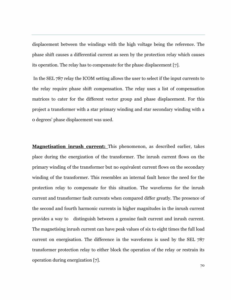
70
displacement between the windings with the high voltage being the reference. The
phase shift causes a differential current as seen by the protection relay which causes
its operation. The relay has to compensate for the phase displacement [7].
In the SEL 787 relay the ICOM setting allows the user to select if the input currents to
the relay require phase shift compensation. The relay uses a list of compensation
matrices to cater for the different vector group and phase displacement. For this
project a transformer with a star primary winding and star secondary winding with a
0 degrees’ phase displacement was used.
Magnetisation inrush current: This phenomenon, as described earlier, takes
place during the energization of the transformer. The inrush current flows on the
primary winding of the transformer but no equivalent current flows on the secondary
winding of the transformer. This resembles an internal fault hence the need for the
protection relay to compensate for this situation. The waveforms for the inrush
current and transformer fault currents when compared differ greatly. The presence of
the second and fourth harmonic currents in higher magnitudes in the inrush current
provides a way to distinguish between a genuine fault current and inrush current.
The magnetising inrush current can have peak values of six to eight times the full load
current on energisation. The difference in the waveforms is used by the SEL 787
transformer protection relay to either block the operation of the relay or restrain its
operation during energization [7].

71
8.2.2 Differential relay configuration
The transformer SEL 787 relay configuration settings shown below in figure 47 below
specify the parameters of the transformer and the associated protection scheme
devices that is current transformers and voltage transformers.
Figure 47 SEL 787 Configuration settings

72
For this project the following settings for the relay were enabled
MVA: Maximum transformer capacity = 50 {transformer rating}. The
maximum transformer rating is used for this taking into account the cooling process
like forced air cooling and pump cooling [9].
ICOM Define internal CT Conn. Compensation = N this defines the phase shift
compensation if required to accommodate phase shifts in transformer winding
connections and also the current transformer connections. The transformer vector
group phase shift and current transformer wiring compensation is done with this
setting. This compensation accommodates for phase shift and removal of zero-
sequence current components [9].
Winding 1 and Winding 2: This denotes the transformer winding configuration.
For this project a two winding transformer with a star primary winding and a star
secondary winding.

73
8.2.3 Differential relay setting
Figure 52 below shows the SEL 787 differential element settings used for the project.
Figure 48 Transformer differential settings

74
8.2.4 O87P Differential Element
This function defines the minimum current required to operate the differential
restrained element. An alarm setting associated with this element 87AT can be set
depending on the application [9]. The protection function was tested using the
ramping method to establish the minimum value to initiate operation of the element.
Both input channels for winding 1 and winding 2 were injected with current. Winding
one current was increased in steps of 0.01 Amps until the protection relay operated.
The 87AT differential alarm function was activated first when the pickup current was
reached and with further increase in the fault current the restrained minimum pickup
element operated. The results are analysed in detailed in the results and analysis
section of this report. Figure 49 below show the differential function logic.
Figure 49 SEL 787 Differential element logic [24]

75
8.2.5 U87P Unrestrained differential element
This protection element as the name implies is not affected by harmonics or
restrained elements activated in the protection relay. It is set to operate
instantaneously and react quickly when there are high current levels that indicate an
internal fault. It only operates for fault currents with the fundamental frequency
component current for the differential quantity. As stated earlier, it is not affected by
the restraint settings of the relay which are SLP1, SLP2, PCT2, PCT5 and IRS1, shown
in figure 48. It is recommended to set this protection element high enough so that it
does not respond to large inrush currents [9]. For this project the setting for this
protection function was 10 that is ten times the tap setting of the relay as indicated in
Figure 48 above. To carry out the fault simulation the fault data on the test template
was set to 20.9 Amps for the three phases. Figure 50 below shows the state sequence
test template used for this simulation with three states: Prefault, fault and post-fault.

76
Figure 50 Test template for unrestrained differential element
8.2.6 Differential element slope 1
One test point was used to investigate the operation of the restrained differential
element in the slope one region. To correctly simulate the operation characteristic in
this region the value of the operation point has to be greater than the intersection of
slope 1 and the minimum operating restriction (0.87P) which has a value of 0.3 shown
in Figure 47 [24]. The restraint value for this operating point has to be less than the
value of the restraint current slope limit IRS, which is the break point between slope 1
and slope 2 as illustrated in Figure 47 [24].

77
The following equation illustrates the operation point 087𝑃 =100
𝑆𝐿𝑃1≤ 𝐼𝑅𝑇 ≤ 𝐼𝑅𝑆
Equation 1 Slope restraint value calculation [27]
To carry out the simulation, current had to be injected in both winding inputs.
Substituting equation (1) with values in the setting 0.3100
25=≤ 𝐼𝑅𝑇 ≤ 3𝑝𝑢
For an IRT of 2 per unit the following operation current is expected for slope 1
𝐼𝑂𝑃 =𝑆𝐿𝑃
100∗ 𝐼𝑅𝑇 = 2 ∗ 0.25 = 0.5𝑝𝑢
Referring to the equations in Figure 45, the input current IW1 an IW2 can be
determined by dividing IRT by the value 2. This calculates the amount of the restraint
current. Addition of half the required value of the operating current to 1W1 and
subtracting half of the operating current from IW2 will result in the operate and
restraint values [24]:
𝐼𝑊1 =(𝐼𝑅𝑇 + 𝐼𝑂𝑃)
2=
(2.0 + 0.5)
2= 1.25𝑝𝑢
Equation 2 Winding 1 test current in per unit [27]
𝐼𝑊2 =(𝐼𝑅𝑇 − 𝐼𝑂𝑃)
2=
(2.0 − 0.5)
2= 0.75𝑝𝑢
Equation 3 Winding 2 test current in per unit [27]
To determine the test currents, the above calculated values are multiplied by the relay
setting tap value.

78
IAW1 = IW1*Tap *CC =1.25*2.09=2.6125Amps
Equation 4 Winding 1 test current in Amps [27]
IAW2 = IW2*Tap *CC =0.75*2.09=1.5675Amps
Equation 5 Winding 2 test current in Amps [27]
For simulation winding 1 was set as the reference 0 degrees and winding 2 set at 180
degrees.
This fault simulation current was injected into the relay, as shown in Figure 55 below.
79
Figure 51 Three phase and single phase fault simulation
8.2.7 Differential element slope 2
To verify correct operation of the relay in the slope 2 region of the differential
operation characteristic, a similar approach to that of slope 1 was undertaken. The
Three phase fault simulation
Single phase fault simulation

80
difference between the slopes, as shown in Figure 46, is that the slope 1 curve is a
straight line passing through the origin but slope 2 does not pass through the origin
but has an offset. Slope 2 has an offset which intersects slope 1 at IRS1 hence slope 2
exists only for values greater than IRS1 [24].
To correctly simulate a fault in this region the following condition has to be satisfied
IRT > IRS1. The setting for IRS1 is 3 as shown in Figure 48. A test point for a value of
5 pu was selected [24].
The operate current for this test point in slope 2 can be calculated:
𝐼𝑂𝑃 =𝑆𝐿𝑃2
100∗ 𝐼𝑅𝑇 + 𝐼𝑅𝑆1 ∗ (
𝑆𝐿𝑃1 − 𝑆𝐿𝑃2
100)
=50
100∗ 5 + 3 ∗ (
25 − 70
100) = 2.05𝑃𝑈
Equation 6 Slope 2 test point [27]
𝐼𝑊1 =(𝐼𝑅𝑇 + 𝐼𝑂𝑃)
2=
(5 + 2.05)
2= 3.525𝑝𝑢
Equation 7 Slope 2 Winding 1 test current per unit [27]
𝐼𝑊2 =(𝐼𝑅𝑇 + 𝐼𝑂𝑃)
2=
(5 − 2.05)
2= 1.475𝑝𝑢
Equation 8 Slope 2 Winding 2 test current per unit [27]
IAW1 = IW1*Tap *CC =3.525*2.09=7.367Amps
Equation 9 Slope 2 Winding 1 test current in Amps [27]

81
IAW2 = IW2*Tap *CC =1.475*2.09=3.083Amps
Equation 10 Slope 2 Winding 2 test current in Amps [27]
This simulation was conducted by injecting the calculated values of the IAW1 and
IAW2.and ramping the winding 2 current down by a value of 0.01 Amps.
The simulation template is shown below:
Figure 52 Slope 2 test card
8.2.8 Magnetization inrush suppression
8.2.8.1 Harmonic blocking
The SEL 787 transformer relay has the capability to provide harmonic blocking for the
second and fourth harmonic content to cater for the transformer inrush currents. The

82
fifth–harmonic content blocking for transformer over-excitation is also catered for as
indicated in Figure 53, the harmonic blocking logic diagram. The relay has the added
feature to perform cross blocking; that is, if one phase of the transformer has the
second and fourth harmonic currents, blocking is done on all the phases. [9]
Figure 53 Harmonic blocking logic [9]
8.2.8.2
8.2.8.3 Harmonic restraint
The harmonic restraint function operates differently from the harmonic blocking
element in that it moves the differential relay characteristic slope line relative to the
magnitude of the harmonic differential current measured by the relay as an input
from the current transformer [27].
8.2.9 Out of zone / through fault operation suppression
Differential protection is a unit scheme protection which only operates for faults in
the protected area demarcated by the location of the current transformers that is F1,

83
shown in Figure 54 below, and shall not operate for out of zone faults F2, as shown
below in Figure 54 [9].
Figure 54 In zone and out of zone faults
Out of zone faults or through faults take place outside the protected zone, as shown in
Figure 56. These faults subject the transformer windings and insulation to mechanical
and thermal stress. Figure 55 shows the category IV transformers time versus current
through fault curves [9].

84
Figure 55 Transformer Time/ Current through fault curves [9]
The transformer protection relay offers an out of zone fault or through fault event
monitor for faults shown in Figure 56. This captures the fault current magnitudes,

85
time and date and the duration of the through fault [9]. The following settings have to
be specified to enable the through fault monitor:
Through fault winding: this specifies which transformer winding to use in
calculating the through fault current [9].
Enable Through-fault monitor: the logic setting to select the different conditions
for the through fault monitor [9].
Through fault pick up alarm: this can be set as a percentage of the predetermined
setting [9].
Transformer impedance: setting of the transformer percentage impedance to
detect the through fault [9].
Sequential Event Report: to monitor the event the through fault alarm, relay word
bits have to be entered in the SER trigger equation TFLTALA, TFLTALB and
TFLTALC [9].
Figure 56 Transformer through fault [9]

86
The test template for the through fault event is shown in Figure 57.
Figure 57 Test template for through fault simulation
8.3 Restricted Earth fault protection
This protection element employs the differential protection philosophy similar the
overall transformer differential protection. It is also a unit protection scheme .and
only operates for earth faults which occur inside the protected zone, as illustrated in
Figure 58. The zone of protection is governed by the location of the current
transformers [10].

87
Figure 58 Restricted earth fault protection [10]
The SEL 787 transformer protection relay as Murdoch University does not have
restricted earth fault hardware circuit board housed in slot E of the relay. It was not
possible to explore the protection element functionality via fault simulations.

88
8.4 Volts/Hertz
This protection element is also known as over-fluxing. Transformer over-fluxing
occurs when the transformer core becomes saturated due to abnormal conditions
arising in the power system. Any conditions occurring in the power system network
which will cause changes to voltage and frequency magnitudes beyond acceptable
levels will affect the voltage and frequency relationship and cause over-fluxing [9].
This protection function is voltage based and, as stated earlier, the SEL 787 protection
relay housed at Murdoch University does not have the voltage input channel card in
slot E, therefore, the operation of this protection element was not investigated.
89
Chapter 9 Results and Analysis
This chapter covers in detail the simulation results of the tests
carried out on the SEL 787 protection relay for the protection
elements already discussed. Verification of correct functional
operation and confirmation of operation within the specified
manufacture tolerances is also discussed in this chapter.
9.1 List of Experiments conducted on the relay
The following protection relay elements were investigated through carrying out
simulations on the relay using the ramping and state sequence techniques:
Instantaneous overcurrent
Negative sequence overcurrent
Residual ground overcurrent
Breaker failure
Unrestrained differential
Restrained differential

90
Slope 1 restrained differential
Slope 2 restrained differential
Through fault monitor
9.2 Instantaneous Overcurrent
To verify correct operation of the instantaneous over current element, the associated
relay word bit was monitored using the TAR 50P11p 11000 command in the terminal
window of the Acselerator software platform shown in Figure 59. Figure 59 shows the
word bit deasserted with the value 0 prior to fault simulation and asserted with the
value 1 after fault simulation.
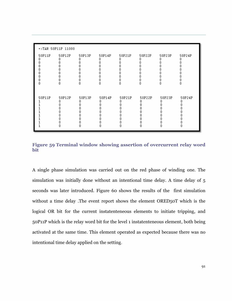
91
Figure 59 Terminal window showing assertion of overcurrent relay word bit
A single phase simulation was carried out on the red phase of winding one. The
simulation was initially done without an intentional time delay. A time delay of 5
seconds was later introduced. Figure 60 shows the results of the first simulation
without a time delay .The event report shows the element ORED50T which is the
logical OR bit for the current instatenteneous elements to initiate tripping, and
50P11P which is the relay word bit for the level 1 instatenteneous element, both being
activated at the same time. This element operated as expected because there was no
intentional time delay applied on the setting.

92
Figure 60 SER showing operation of overcurrent element
In comparison, for the same overcurrent setting but with a setting change on the time
delay of 5 seconds: the element relay word bit 50P11P asserted first and after 5
seconds the ORED50T word bit and a trip signal was sent after a period of 5 seconds,
as shown in Figure 61 below.
Figure 61 SER showing time delay for overcurrent
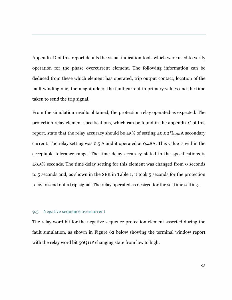
93
Appendix D of this report details the visual indication tools which were used to verify
operation for the phase overcurrent element. The following information can be
deduced from these which element has operated, trip output contact, location of the
fault winding one, the magnitude of the fault current in primary values and the time
taken to send the trip signal.
From the simulation results obtained, the protection relay operated as expected. The
protection relay element specifications, which can be found in the appendix C of this
report, state that the relay accuracy should be ±5% of setting ±0.02*INom A secondary
current. The relay setting was 0.5 A and it operated at 0.48A. This value is within the
acceptable tolerance range. The time delay accuracy stated in the specifications is
±0.5% seconds. The time delay setting for this element was changed from 0 seconds
to 5 seconds and, as shown in the SER in Table 1, it took 5 seconds for the protection
relay to send out a trip signal. The relay operated as desired for the set time setting.
9.3 Negative sequence overcurrent
The relay word bit for the negative sequence protection element asserted during the
fault simulation, as shown in Figure 62 below showing the terminal window report
with the relay word bit 50Q11P changing state from low to high.

94
Terminal window showing assertion of negative sequence relay word bit
Figure 62 Terminal window showing assertion of negative sequence relay word bit
Appendix E of this report shows the tools used to verify the operation of the negative
phase sequence protection element. The relay operated correctly for the specified
setting of 0.3Amps. Figure 40 shows the actual fault simulation values of 0.1Amps
injected into the relay winding 1 input. From Figure 38, three times the negative
sequence current will cause the relay to operate and as stated before for all relay
elements the accuracy has to be ±5% of the nominal setting as per relay specifications.

95
9.4 Residual ground overcurrent
For the residual overcurrent setting, shown in Figure 63, with current 0.6Amps and 5
seconds time delay, the relay operated as expected. The relay operated for a value of
0.68 Amps on the red phase and the relay word bit 50G11P asserted, as shown in
Figure 65. The protection relay element operated accurately for the time delay setting
of 5 seconds, as shown in the sequential event report shown in Figure 66.
Figure 63 Residual overcurrent setting page
Figure 64 below show the simulation template used to carry out the test.
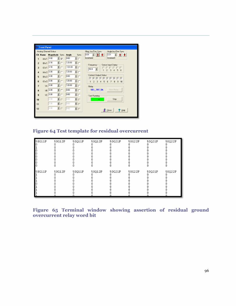
96
Figure 64 Test template for residual overcurrent
Figure 65 Terminal window showing assertion of residual ground overcurrent relay word bit

97
Figure 66 SER showing operation of residual overcurrent element
Appendix F of this report shows the visual indications verifying operation of the
protection element.
9.5 Breaker Failure
This back up protection function operated as desired after the trip signal had been
sent to trip the circuit breaker and the input from the auxiliary contact of the breaker
was not received by the relay to indicate circuit breaker operation. Figure 67 shows
the breaker failure word bit BFT getting asserted.

98
Figure 67 Assertion of breaker failure
The sequential event report below shows all the relay word bits associated with the
simulation getting asserted. The time taken to activate the relay word bits is also
shown. The function operated correctly, as indicated by the sequence of events shown
in Figure 68.

99
Figure 68 SER indicating operation of the breaker failure element

100
9.6 Unrestrained differential element
The unrestrained relay word bit was activated when the setting value of 20.9 Amps
was reached, as shown in the simulation template in Figure 69. Figure 69 also shows
the relay word bit for the unrestrained element 87U changing state and the sequential
event report generated. The restrained differential word bit also changed state as the
restrained differential element minimum pick up setting is much lower than the
unrestrained pick up value, hence the relay word bit 87R also got activated.

101
Figure 69 Unrestrained differential element operation
Simulation Template
Relay word bit activated

102
9.7 Restrained differential
The relay word bit for the differential alarm function 87AT element asserted during
the fault simulation, as shown in Figure 70. The time delay for the alarm was set at 5
seconds. The protection function was tested at a setting of 0.15 with a 2.09 tap value.
The alarm word bit asserted for a three phase fault simulation with a value of 0.41
Amps on all three phases for winding 1, as shown in Figure 70.
From the equation for the operate current IOP=(|𝐼𝑊 ⃐ 1+I𝑊2 ⃐ |),
Equation 11 Differential operate current [9]
Using one of the phases as an example, the differential current can be calculated for
this simulation as 0.14<00+0.1<1800 =0.31Amps. The expected operating current for
the alarm from the settings is 0.15*2.09=0.3135. The simulation results are accurate
as specified by the accuracy limits with a tolerance of ±2%. Figure 70 also shows the
differential metering values for the , restraint current and differential operating
current in per unit (pu). From the metering display it can also be verified that the
relay operated correctly for a differential current of 0.3pu which is exactly the same as
the setting value of 0.3pu.

103
Figure 70 Restrained differential element simulation template and results
Relay word bit activated
Simulation Template

104
9.8 Slope 1 Restrained differential element
The protection element operated as expected in the slope one region on single phase
and three phase fault simulations, as indicated in Figure 71. From Figure 71, the relay
operated as desired in the slope one region with a differential operating current of
0.52pu and restraint current of 2.06 verifying the region of operation from the
characteristic curve shown in Figure 44.
Figure 71 Slope 1 differential element operation results
Figure 72 shows the differential element restrained word bit being activated for the
slope 1 simulation, and the sequential event report shown in Figure 73 details the time
and date the event occurred and the element word bits which were asserted are the
differential alarm 87AT, restrained differential 87R and the transformer trip

105
TRIPXFMR. The device overview metering display Figure 74 shows the primary
values of the injected current during the simulation.
Figure 72 Restrained element relay word bit activation
Figure 73 SER report for restrained element operation

106
Figure 74 Slope 1 Differential simulation values in primary values
9.9 Slope 2 Restrained differential element
The protection element operated as expected in the slope two region on single phase
and three phase fault simulations, as indicated in Figure 75.
107
From Figure 75 showing the differential metering values during the fault simulation,
the relay operated correctly in the slope two region with a differential operating
current of 2.21pu and restraint current of 5.08, verifying the region of operation from
the characteristic settings shown in Figure 48. The restraint current is above 3pu, as
shown in Figure 75, which is the IRS value confirming that the fault simulation is in
second slope region.
Figure 75 Slope 2 differential element operation results
Figure 76 shows the event summary of the differential restrain element 87R operating
in the slope 2 region. The associated relay word bit was asserted as shown by the
terminal window report in Figure 77.

108
Figure 76 SER report for restrained element slope 2 operation
Figure 77 Slope 2 Restrained element relay word bit activation
The device overview metering displaying primary values of the injected current and
indicators confirming correct operation of the protection element are shown in Figure
78 below.

109
Figure 78 Slope 2 Differential simulation values in primary values

110
9.10 Through fault monitor
The values injected into the relay were 20.9 Amps above the unrestrained pick up
value, and the relay did not operate. Through fault measurement for injected current
of 20.9 A on all phases: on the primary side, the currents have a phase displacement
of 120 degrees; and on the secondary side, as seen by the relay, the currents are
displaced 180 degrees. This is for a three phase fault hence all the currents are the
same. The relay did not operate because the simulation was for an out of zone fault.
The device metering overview display below shows the primary values of the through
fault event as seen by the relay. No output trip was activated as the relay restrained
and did not operate.

111
Figure 79 Through fault simulation metering overview

112
The differential metering values, as can be seen below in Figure 80, is 0, hence the
relay did not operate. The restrain current shot up to 20pu, also indicating that the
relay is restraining operation, as shown in Figure 80.
Figure 80 Differential metering view through fault
Even without the relay operating, the through fault event report indicates this event.
The through fault event report in Figure 81 shows the number of through fault events,
and the latest event on the 13th of December is associated with the differential
metering report above.
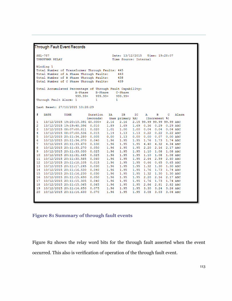
113
Figure 81 Summary of through fault events
Figure 82 shows the relay word bits for the through fault asserted when the event
occurred. This also is verification of operation of the through fault event.

114
Figure 82 Through fault relay word bit assertion

115
Chapter 10 LabVIEW/CompactDaq system
10.1 CompactDaq
The CompactDaq system by National Instruments is a robust modular data
acquisition platform. The system is mainly used in the chemical and process
industries to capture process data from sensors and to facilitate its measurement and
analysis through software programs like LabVIEW. In this project, the Ethernet
chassis consisted of eight slots where the analog or digital modules are inserted. The
chassis is robust and can withstand shocks of 30Kg to 50Kg. Figure 83 shows the
Ethernet chassis [26].
Figure 83 Ethernet CompactDaq chassis [26]

116
The modules, both analog and digital, have a signal converter, circuitry for filtering,
conditioning circuitry excitation and signal amplification. Figure 84 shows the
different types of modules [26].
Figure 84 CompactDaq Modules [26]
For this project, the NI9263 was used to provide the necessary analog signals to carry
out fault simulations. The module has an output analog range of ±10V. Figure 85
shows the module and the test setup for fault simulation. The wiring configuration of
the module and specifications can be found in the appendix A section of this report
[26].

117
Figure 85 CompactDaq test setup
10.2 NI Max
LabVIEW is a graphical programming language developed by National Instruments.
It is a powerful tool used in many industries for data acquisition, measurement and
analysis. LabVIEW can be used in conjunction with the CompactDaq system via NI-
DAQmx drivers. Figure 86 shows the NI Max platform which was used to conduct the
fault simulation via the test panel.

118
Figure 86 NI Max test panel
10.3 Signal output measurement and analysis
Prior to using the CompactDaq system for testing, the fault simulation signals to the
protection relay slot Z input card needed to be analysed to determine the condition of
the signal. This was carried out using an oscilloscope to measure the signal inputs as
shown in Figure 87.

119
Figure 87 Signal analysis test setup
The signal outputs from the CompactDaq system and the analog inputs to the relay
from the simulator were measured via an oscilloscope and compared. Initially, the
signals were compared at different output values to show the output waveform at low
voltage values as shown in Figure 88. The input signal to the relay circuit board was
found to be a voltage signal of a peak to peak value of 10V maximum for the SEL 787
relay as shown in Figure 89. After determining this value, the NI max analog output
voltage value was set to match a peak to peak value of 10V at 50Hz.

120
Figure 88 Initial test simulation of output voltages
Figure 89 Maximum Output Voltages
Output signal from the CompactDaq
Output signal from the simulator
Output signal from the CompactDaq
Output signal from the simulator

121
10.4 Testing relay using NI Max
After establishing the maximum voltage, the slot Z circuit board can take the test
panel setting in the NI. Max platform was set at the same maximum values. This was
done to prevent damage to the circuit board through accidental injection of voltages
above the maximum input voltage for the circuit board. Figure 90 shows the page
where the test settings can be changed.
Figure 90 NI Max test platform

122
The relay was successfully tested using the CompactDaq system. The differential
protection element 87, as previously described, was tested and the relay operated, as
shown in Figure 91 which shows the test setup.
Figure 91 Fault simulation using CompactDaq system

123
Chapter 11 Conclusion
This thesis has reviewed power transformer operation and protection. Work has been
successfully conducted on the use of low level simulators in showcasing the
capabilities of microprocessor-based protection relays using the SEL 787 transformer
protection relay.
This thesis described the different types of testing methodologies and analysis of
simulation results for transformer protection relays. In the project the current based
protection elements for the SEL 787 protection relay were successfully tested. The
knowledge acquired throughout the project led to the initial development of a low
level simulator using LabVIEW and the CompactDaq system, previous attempts by
Murdoch University students had been unsuccessful.
Finally, the presented method of using low level simulators in relay testing has many
benefits including the following:
Providing low level signals that actual resemble the actual faults which occur in
power systems.
Setting up the hardware and wiring is less tedious hence a lot of time is saved.
More time can then be spent on programming and testing the relay instead of
wiring.
It is a flexible, easy to implement low cost system compared to high level
simulation.
124
Chapter 12 Future Work
While this thesis has showcased the capabilities of the SEL 787 transformer
protection relay and the development of a low level simulator using LabVIEW and the
CompactDaq system, the present study could be further extended. This section details
some of the potential directions:
1. The protection relay functions for Harmonic restraint and blocking simulation
was not investigated in the present study. This can be carried out by applying
two current signals to the relay in parallel, one at the fundamental frequency of
50Hz and the other input at 2nd4th or 5th harmonics.
2. Simulations to verify the time current characteristics of the relay were not
conducted. This can be done by monitoring the time it takes for the relay
output contacts to operate for a specified fault current and plotting the data.
This data can then be compared to the standard time current characteristic
curves
3. Simulation using CompactDaq was done using the NI max test panel to
conduct the testing of the relay elements. The next step is to design a robust
CompactDaq system simulation station with the associated LabVIEW
simulation program not to cater for all the relays housed at Murdoch
University.

125
Chapter 13 References
[1] J.D Glover, M.S. Sarma and T.J Overbye, Power System Analysis and Design,
Ed., 4th ed. USA: Thomson Learning, 2008 [Online]. Available:
http://www.abookey.net/q/title/system-analysis-and-design-4th-
edition.html
[2] Alstom T & D Protection and Control, Protection Relays, Application Guide.
Stafford, England: ICA, 1987.
[3] Ravindranath and M. Chander, Power Systems Protection and Switchgear.
New Delhi: Wiley Eastern Limited, 1977.
[4] Christopoulos and A. Wright, Electrical Power System Protection (2nd ed.).
Netherlands: Kluwer Academic Publishers, 1999.
[5] Electricity Training Association, Power System Protection, London: Institute
of Electrical engineers, 1995.
[6] L.G. Hewitson, M. Brown and R. Balakrishman, Practical Power Systems
Protection. Burlington: IDC Technologies, 2004.
[7] M. J. Gers and E.J. Holmes, Protection of Electricity Distribution Networks
(2nd ed.). London: Institute of Electrical Engineers, 2004.
[8] Schweitzer Engineering Laboratories, Sel-Rts Relay Test System Sel-Ams
Adaptive Multichannel Source Seltest™ Software (Ms Dos) Sel-5401 Test

126
System Software (Windows®95, Windows.NET)
(FEBRUARY3,1997)[Online].Available:
http://www.electricalpartmanuals.com/pdf/relaysAndMeters/Schw
eitzer%20Engineering%20Laboratories,%20Inc./Relay%20Systems
/970203.pdf
[9] Schweitzer Engineering Laboratories Inc. SEL-787 Relay Transformer
Protection Relay Instruction Manual (2012) [Online]. Available:
https://www.selinc.com/SEL-787/
[10] F. Shahnia, M. Moghbel and H. H. Yengejeh, Improving the Learning
Experience of Power System Protection Students using Computer-based
Simulations and Practical Experiments, Electrical and Computer Engineering
Department Curtin University, Perth Australia
[11] F Calero, Rebirth of Negative-Sequence Quantities in Protective Relaying with
Microprocessor-Based Relays: Schweitzer Engineering Laboratories, Inc.
2008.
[12] T Edmund and O. Schweitzer, Negative-Sequence Overcurrent Element
Application and Coordination in Distribution Protection, Schweitzer
Engineering Laboratories, Inc., Pullman, 1997.
[13] N. Kilburn, SEL Protection and Monitoring System, School of Engineering and
Information Technology Murdoch University, 2013.
127
[14] Gfuve Electricals, “Protection Relay Test Equipment,” 2012. [Online].
Available
https://www.google.com.au/search?q=protection+relay+test+equipment+pict
ures&biw=1024&bih=696&tbm=isch&tbo=u&source=univ&sa=X&ved=0CDE
Q7AlqFQoTCLOrt5fwlccCFYIWpgodNwQJ6w#imgrc=_
[15] Doble, Transformer Construction, (2015) [Online]. Available
http://events.doble.com/loatdubai/ [Accessed: Dec. 12, 2015]
[16] National Instruments, “NI CompactDAQ,” 2011 [Online]
http://www.ni.com/data-acquisition/compactdaq [Accessed: Aug. 6, 2015].
[17] Sai Global, IEC 60255-5 Ed. 2.0 Electrical Relays - Part 5: Insulation
coordination for measuring relays and protection equipment - Requirements
and tests. IEC, 2008.
[18] IEEE, Electrical Power System Device Function Numbers, Acronyms, and
Contact Designations C37.2, 2008.
[19] Guzman, N. Fischer, and C Labuschagne, Improvements in Transformer
Protection and Control. Schweitzer Engineering Laboratories, Inc. 2011
[20] Schweitzer Engineering Laboratories, Inc., “SEL-751A Feeder Protection Relay
New user Training,” Schweitzer Engineering Laboratories, Inc., Pullman,
2012.
[21] Network Protection and Automation Guide, 1st ed. France: Areva, 2002.

128
[22] ABB, Universal Testing Method for Power Transformer Differential
Protection, ABB. 2007
[23] National Instruments, Operating Instructions and Specifications Ni 9263,
2007. [Online]. Available https://www.ni.com/manuals [Accessed Dec. 15,
2015].
[24] J. Young, Single-Phase Testing of the SEL-787 Differential Element:
Application Guide, Schweitzer Engineering Laboratories, Inc. [n.d]
[25] Z. Gaji and F. Mekic, Easy and Intuitive Method for Testing Transformer
Differential Relays Vasteras, Sweden Allentown, PA. 2008
[26] What is NI Compaq DAQ”, 2011 [Online]
http://www.ni.com/compactdaq/whatis/) [Accessed: Nov 2014].
[27] J. Young, Single-Phase Testing of the SEL-787 Harmonic Blocking and
Restraint Functions: Application Guide, Schweitzer Engineering Laboratories,
Inc. [n.d]

129
Chapter 14 Appendices
14.1 Appendix A CompactDaq Wiring Connection

130
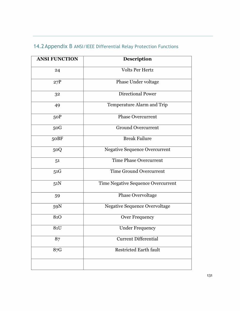
131
14.2 Appendix B ANSI/IEEE Differential Relay Protection Functions
ANSI FUNCTION Description
24 Volts Per Hertz
27P Phase Under voltage
32 Directional Power
49 Temperature Alarm and Trip
50P Phase Overcurrent
50G Ground Overcurrent
50BF Break Failure
50Q Negative Sequence Overcurrent
51 Time Phase Overcurrent
51G Time Ground Overcurrent
51N Time Negative Sequence Overcurrent
59 Phase Overvoltage
59N Negative Sequence Overvoltage
81O Over Frequency
81U Under Frequency
87 Current Differential
87G Restricted Earth fault

132
14.3 Appendix C SEL 787 Relay Specifications

133

134

135

136
14.4 Appendix D Overcurrent protection element simulation results
Ascelerator human machine interface

137
Relay front panel indication

138
Event summary verifying operation
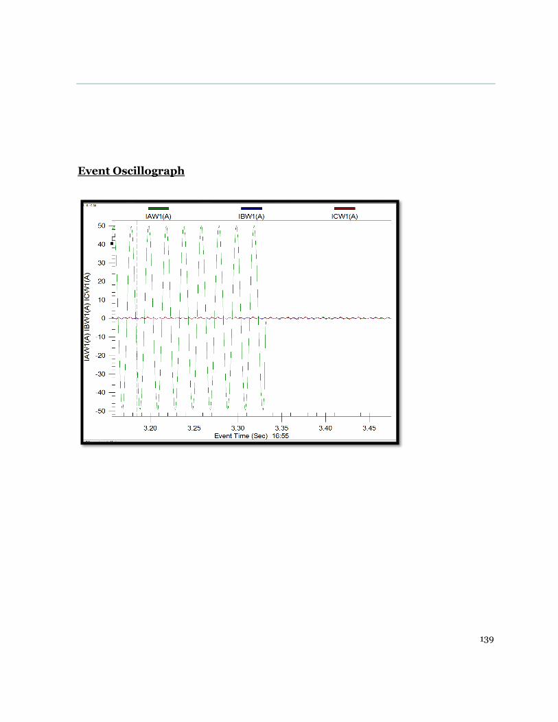
139
Event Oscillograph
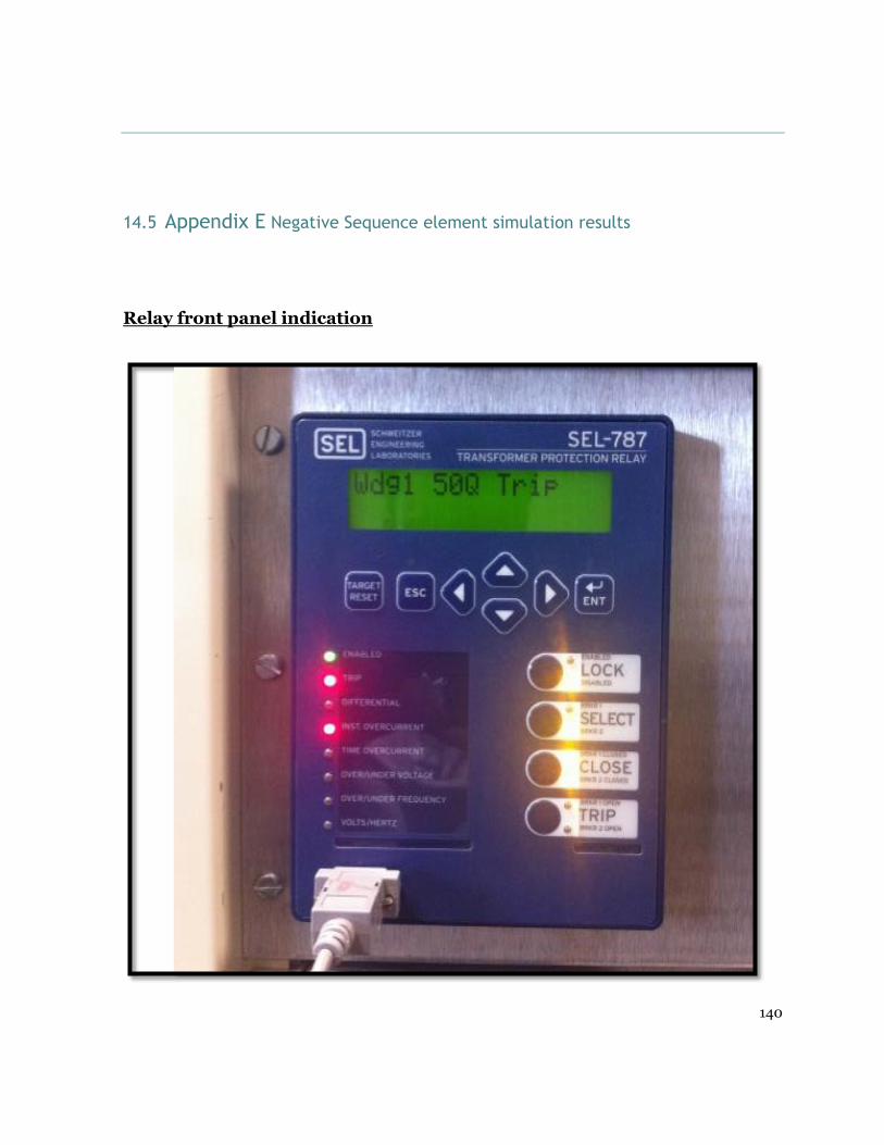
140
14.5 Appendix E Negative Sequence element simulation results
Relay front panel indication

141
Ascelerator Human machine Interface
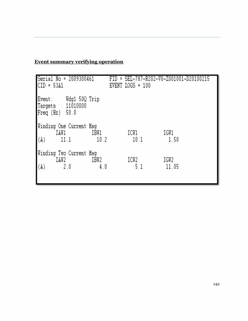
142
Event summary verifying operation
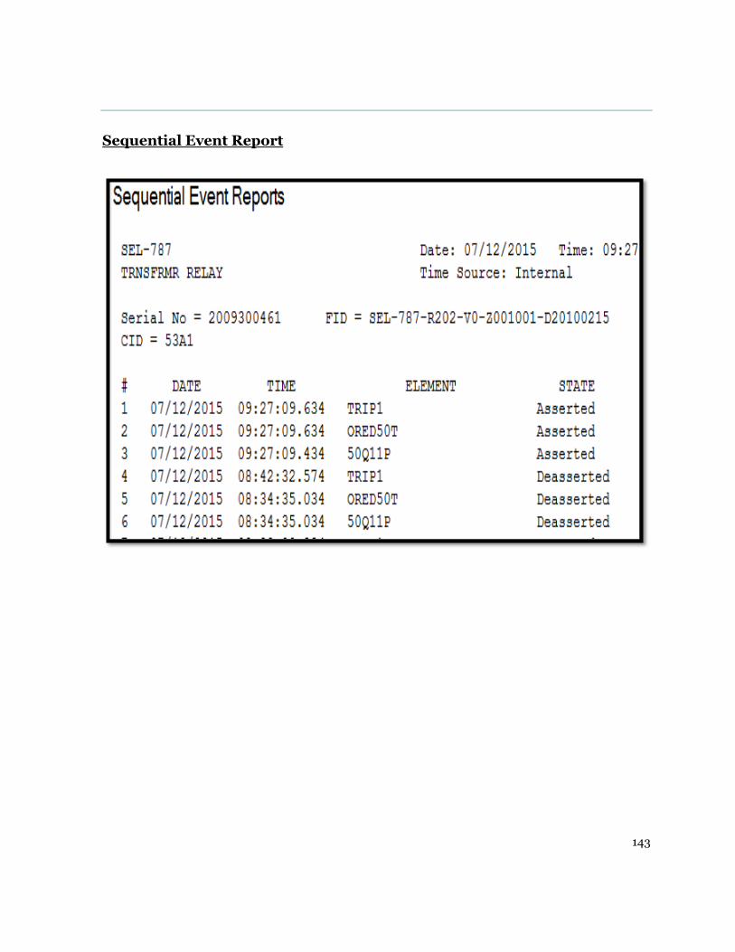
143
Sequential Event Report

144
14.6 Appendix G Residual Ground (50G) element simulation results
Relay front panel indication

145
Ascelerator human to machine interface

146
Event summary verifying operation

147
Event Oscillograph

148
14.7 Appendix G Unrestrained differential protection (87) element
simulation results
Relay front panel indication
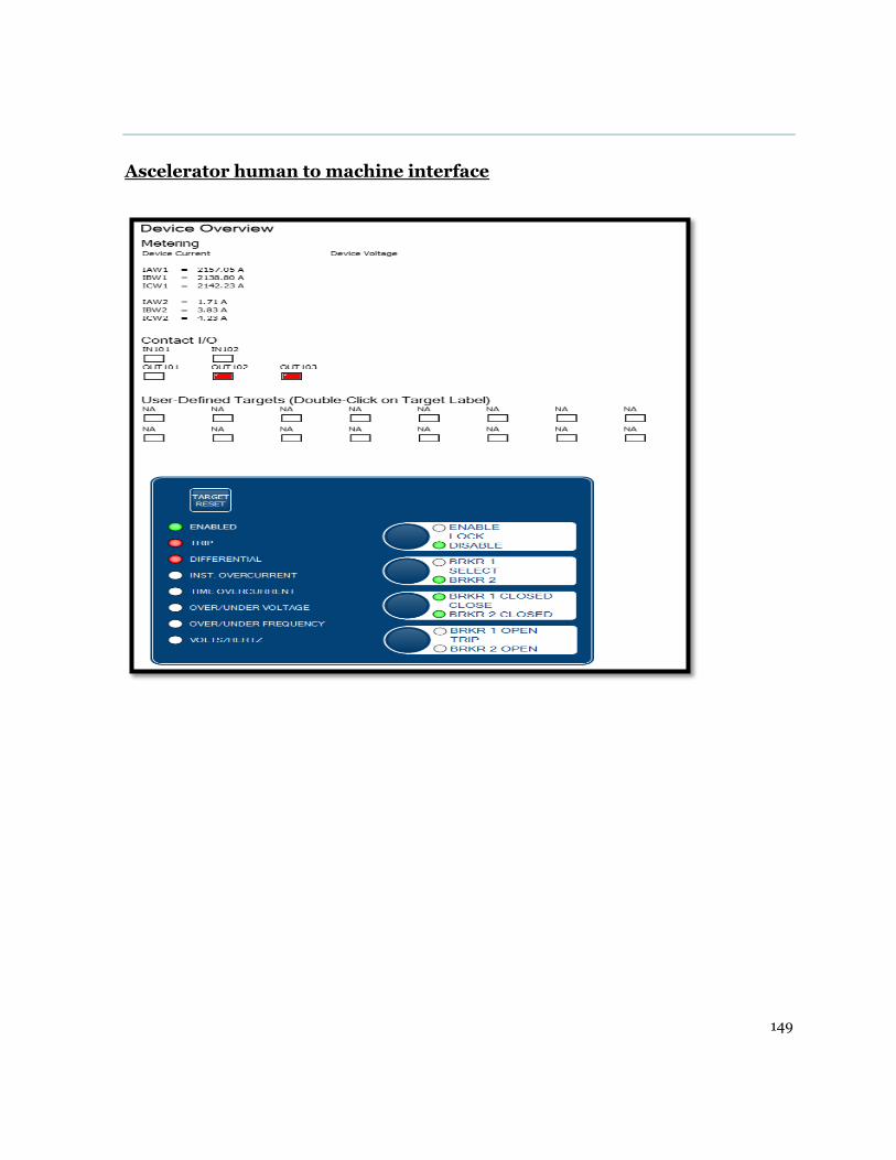
149
Ascelerator human to machine interface
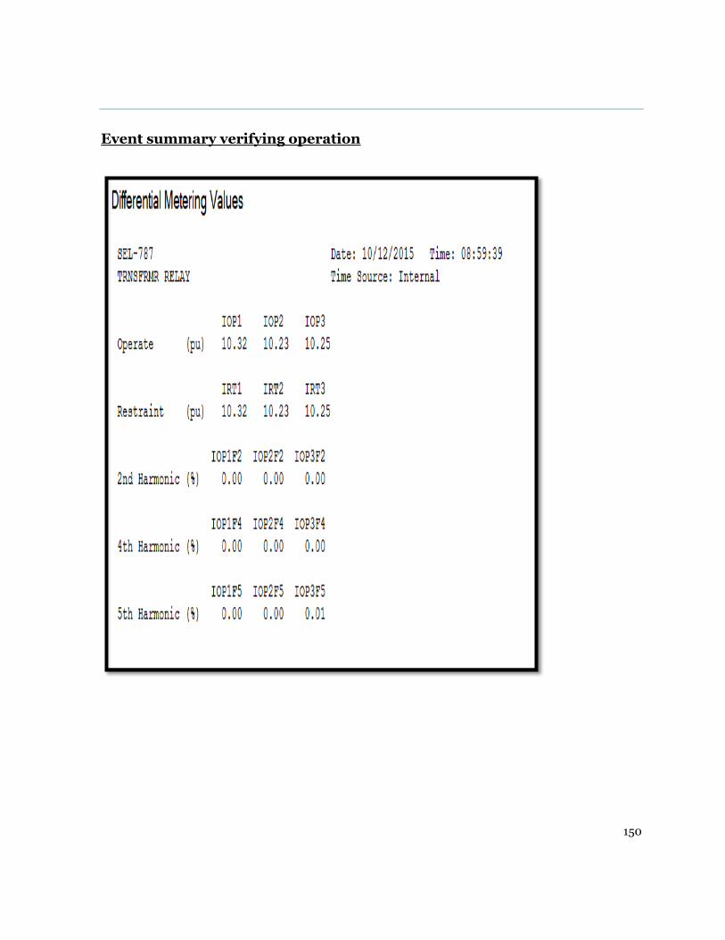
150
Event summary verifying operation

151
Event Oscillograph