Inverters Catalogue
52
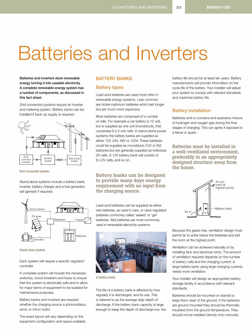
6.9 BATTERIES AND INVERTERS ENERGY USE 213 Batteries and Inverters Batteries and inverters store renewable energy turning it into useable electricity. A complete renewable energy system has a number of components, as discussed in this fact sheet. Grid connected systems require an inverter and metering system. Battery banks can be installed if back up supply is required. Grid connected system. Stand-alone systems include a battery bank, inverter, battery charger and a fuel generator set (genset) if required. Stand alone system. Each system will require a specific regulator/ controller. A complete system will include the necessary switches, circuit breakers and fuses to ensure that the system is electrically safe and to allow for major items of equipment to be isolated for maintenance purposes. Battery banks and inverters are required whether the charging source is photovoltaics, wind, or micro hydro. The exact layout will vary depending on the equipment configuration and space available. BATTERY BANKS Battery types Lead-acid batteries are used most often in renewable energy systems. Less common are nickel-cadmium batteries which last longer but are much more expensive. Most batteries are composed of a number of cells. For example a car battery is 12 volt, but is supplied as one unit (monoblock), that comprises 6 x 2 volt cells. In stand-alone power systems the battery banks are supplied as either 12V, 24V, 48V or 120V. These batteries could be supplied as monoblock (12V or 6V) batteries but are generally supplied as individual 2V cells. A 12V battery bank will consist of 6 x 2V cells, and so on. Battery banks can be designed to provide many days energy requirement with no input from the charging source. Lead-acid batteries can be supplied as either wet batteries, as used in cars, or valve regulated batteries commonly called ‘sealed’ or ‘gel’ batteries. Wet batteries are most commonly used in renewable electricity systems. The life of a battery bank is affected by how regularly it is discharged, and its use. This is referred to as the average daily depth of discharge. If the battery bank capacity is large enough to keep the depth of discharge low, the battery life should be at least ten years. Battery manufacturers will provide information on the cycle life of the battery. Your installer will adjust your system to comply with relevant standards and maximise battery life. Battery installation Batteries emit a corrosive and explosive mixture of hydrogen and oxygen gas during the final stages of charging. This can ignite if exposed to a flame or spark. Batteries must be installed in a well-ventilated environment, preferably in an appropriately designed structure away from the house. Because the gases rise, ventilation design must permit air to enter below the batteries and exit the room at the highest point. Ventilation can be achieved naturally or by installing fans and electrical vents. The amount of ventilation required depends on the number of battery cells and the charging current. A large battery bank using large charging currents needs more ventilation. Your installer will design an appropriate battery storage facility in accordance with relevant standards. Batteries should be mounted on stands to keep them clear of the ground. If the batteries are ground mounted they should be thermally insulated from the ground temperature. They should not be installed directly onto concrete, Grid connect inverter Switch board Electricity meter Wind turbine PV array Regulator Batteries Inverter Generator Geoff Stapleton A battery bank. )
-
date post
11-Sep-2014 -
Category
Technology
-
view
1.773 -
download
9
description
Inverter Catalogue
Transcript of Inverters Catalogue
6.8 WIND SYSTEMS 6.9 BATTERIES AND INVERTERS6.9 BATTERIES AND INVERTERS ENERGY usE213
Batteries and InvertersBatteries and inverters store renewable energy turning it into useable electricity. A complete renewable energy system has a number of components, as discussed in this fact sheet.
Grid connected systems require an inverter and metering system. Battery banks can be installed if back up supply is required.
Grid connected system.
Stand-alone systems include a battery bank, inverter, battery charger and a fuel generator set (genset) if required.
Stand alone system.
Each system will require a specific regulator/controller.
A complete system will include the necessary switches, circuit breakers and fuses to ensure that the system is electrically safe and to allow for major items of equipment to be isolated for maintenance purposes.
Battery banks and inverters are required whether the charging source is photovoltaics, wind, or micro hydro.
The exact layout will vary depending on the equipment configuration and space available.
BAttery BAnks
Battery types
Lead-acid batteries are used most often in renewable energy systems. Less common are nickel-cadmium batteries which last longer but are much more expensive.
Most batteries are composed of a number of cells. For example a car battery is 12 volt, but is supplied as one unit (monoblock), that comprises 6 x 2 volt cells. In stand-alone power systems the battery banks are supplied as either 12V, 24V, 48V or 120V. These batteries could be supplied as monoblock (12V or 6V) batteries but are generally supplied as individual 2V cells. A 12V battery bank will consist of 6 x 2V cells, and so on.
Battery banks can be designed to provide many days energy requirement with no input from the charging source.
Lead-acid batteries can be supplied as either wet batteries, as used in cars, or valve regulated batteries commonly called ‘sealed’ or ‘gel’ batteries. Wet batteries are most commonly used in renewable electricity systems.
The life of a battery bank is affected by how regularly it is discharged, and its use. This is referred to as the average daily depth of discharge. If the battery bank capacity is large enough to keep the depth of discharge low, the
battery life should be at least ten years. Battery manufacturers will provide information on the cycle life of the battery. Your installer will adjust your system to comply with relevant standards and maximise battery life.
Battery installation
Batteries emit a corrosive and explosive mixture of hydrogen and oxygen gas during the final stages of charging. This can ignite if exposed to a flame or spark.
Batteries must be installed in a well-ventilated environment, preferably in an appropriately designed structure away from the house.
Because the gases rise, ventilation design must permit air to enter below the batteries and exit the room at the highest point.
Ventilation can be achieved naturally or by installing fans and electrical vents. The amount of ventilation required depends on the number of battery cells and the charging current. A large battery bank using large charging currents needs more ventilation.
Your installer will design an appropriate battery storage facility in accordance with relevant standards.
Batteries should be mounted on stands to keep them clear of the ground. If the batteries are ground mounted they should be thermally insulated from the ground temperature. They should not be installed directly onto concrete,
Grid connectinverter
Switchboard
Electricitymeter
Grid connected system
Wind turbine
PV arrayRegulator
Batteries
Inverter
Generator
Stand alone power system (SAPS)
Geoff Stapleton
A battery bank.
)
6.9 BATTERIES AND INVERTERSENERGY usE 6.9 BATTERIES AND INVERTERS214 6.9 BATTERIES AND INVERTERS
as concrete will cool to ground temperature, causing the electrolyte to stratify. This is detrimental to a battery’s long-term life and performance. Low electrolyte temperatures also reduce the capacity of a battery.
Batteries must not be installed where they will be exposed to direct sunlight, as high temperatures may cause electrodes to buckle.
The typical area required for the installation of a battery bank is:
12V 1.4m x 0.3m or 0.7m x 0.6m
24V 1.4m x 0.6m
48V 2.8m x 0.6m
The batteries can be as high as 700mm, and if installed in a box it must have a removable lid or at least 500mm clearance above them to allow access for a hygrometer to check the charge level.
Access to the battery room or container should be limited to responsible people trained in system maintenance and shut down procedures.
Safety signs are required in accordance with Australian Standards.
The installation must include a switch/fuse near the batteries to enable the bank to be electrically isolated from the rest of the system.
Battery maintenance
Battery maintenance includes keeping terminals clean and tight and ensuring the electrolyte is kept above minimum levels. Use only distilled water when topping up the electrolyte level.
Batteries are dangerous items and must be treated cautiously. There are three main dangers with batteries:
> Explosion or fire from the battery gases.
> Short-circuiting the terminals.
> Acid burns from wet, lead-acid batteries.
Ensure that when working with batteries you do not short across the battery terminals. Under Australian Standards the terminals must be covered (shrouded) to prevent accidental shorting.
Wet, lead-acid batteries hold a fluid electrolyte that contains sulphuric acid. This can cause serious burns to the skin and eyes. Always wear protective clothing and eye protection. If ‘acid’ is spilt on the floor or equipment, it must be diluted with water and neutralised with sodium bi-carbonate. These should be readily accessible and stored near the battery bank.
Batteries need specific charge regimes that include equalisation charging. The system designer will explain this process. The equalisation charge will either be controlled by the system or require the owner to connect a generator and battery charger. Specific gravity readings are the best method to determine the charge level. A safe method for performing this will be explained by the system designer.
System owners should read and fully understand the manufacturer’s manual for their battery bank.
Battery disposal
Batteries contain lead and acid that are harmful to the environment. When a battery bank is being replaced the old batteries should be disposed of at a battery recycling station or other suitable site.
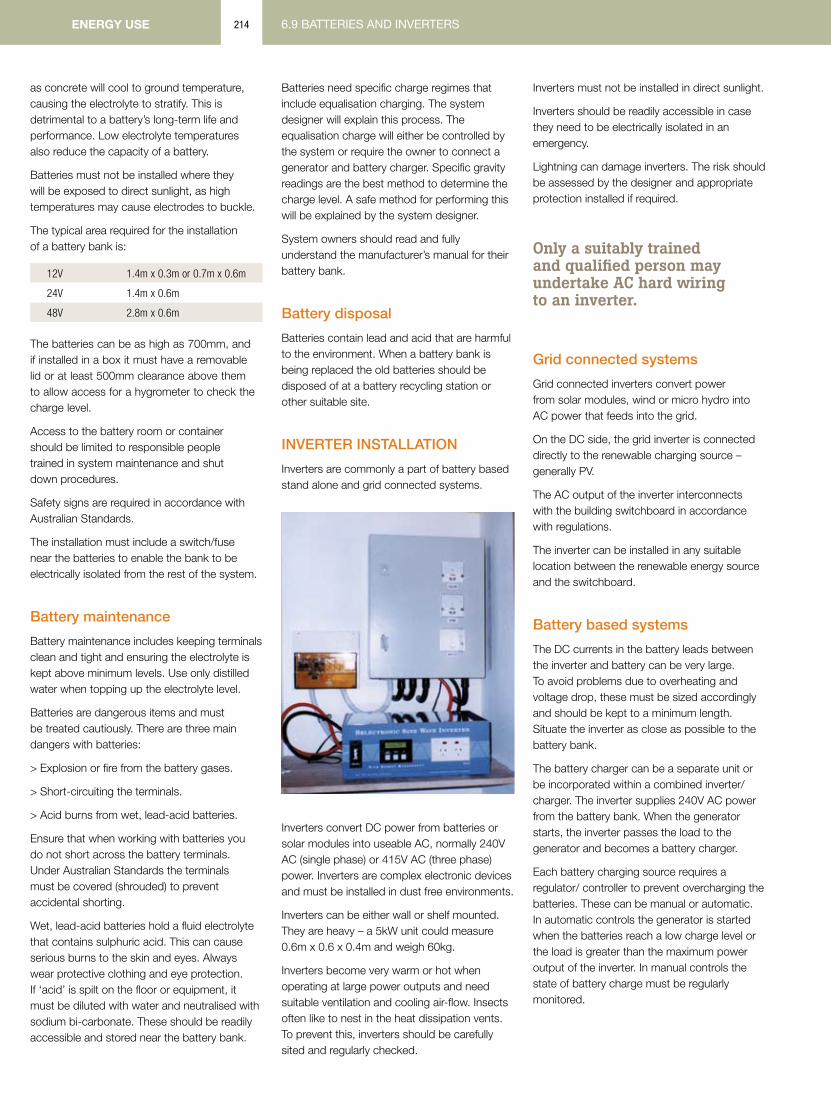
Inverter InstAllAtIon
Inverters are commonly a part of battery based stand alone and grid connected systems.
Inverters convert DC power from batteries or solar modules into useable AC, normally 240V AC (single phase) or 415V AC (three phase) power. Inverters are complex electronic devices and must be installed in dust free environments.
Inverters can be either wall or shelf mounted. They are heavy – a 5kW unit could measure 0.6m x 0.6 x 0.4m and weigh 60kg.
Inverters become very warm or hot when operating at large power outputs and need suitable ventilation and cooling air-flow. Insects often like to nest in the heat dissipation vents. To prevent this, inverters should be carefully sited and regularly checked.
Inverters must not be installed in direct sunlight.
Inverters should be readily accessible in case they need to be electrically isolated in an emergency.
Lightning can damage inverters. The risk should be assessed by the designer and appropriate protection installed if required.
Only a suitably trained and qualified person may undertake AC hard wiring to an inverter.
Grid connected systems
Grid connected inverters convert power from solar modules, wind or micro hydro into AC power that feeds into the grid.
On the DC side, the grid inverter is connected directly to the renewable charging source – generally PV.
The AC output of the inverter interconnects with the building switchboard in accordance with regulations.
The inverter can be installed in any suitable location between the renewable energy source and the switchboard.
Battery based systems
The DC currents in the battery leads between the inverter and battery can be very large. To avoid problems due to overheating and voltage drop, these must be sized accordingly and should be kept to a minimum length. Situate the inverter as close as possible to the battery bank.
The battery charger can be a separate unit or be incorporated within a combined inverter/charger. The inverter supplies 240V AC power from the battery bank. When the generator starts, the inverter passes the load to the generator and becomes a battery charger.
Each battery charging source requires a regulator/ controller to prevent overcharging the batteries. These can be manual or automatic. In automatic controls the generator is started when the batteries reach a low charge level or the load is greater than the maximum power output of the inverter. In manual controls the state of battery charge must be regularly monitored.

6.9 BATTERIES AND INVERTERS 6.9 BATTERIES AND INVERTERS6.9 BATTERIES AND INVERTERS ENERGY usE215
Battery charger installation
If the stand alone power system installation includes a separate battery charger, it should be treated in a similar manner to the inverter. Chargers are generally no larger than 0.4m x 0.4 x 0.6m and weigh up to 40kg.
The charger must be installed close to the batteries and can be floor or shelf mounted. The input power to the charger must be a generator-only power point.
GenerAtor InstAllAtIon
The generator should be installed in a separate room or enclosure. If installed in the same room as the rest of the system it should be located as far away from other components as possible. This helps prevent excessive heating and contamination from a malfunctioning exhaust.
Sufficient space should be allowed around the generator for maintenance.
Generators can be noisy, so locate and design the enclosure to minimise noise.
The generator fuel must be kept in an approved container in a safe location.
AdditionAl REAdinG
Contact your State / Territory government or local council for further information on renewable energy, including what rebates are available. www.gov.au
ReNew, Batteries Buyers Guide, Issue 98 and Inverters Buyers Guide, Issue 87. www.renew.org.au
Principal authors: Geoff Stapleton Geoff Milne
Contributing author: Chris Riedy

10th Edition • Solar Electric Products Catalog • March 2003
While an inverter can account for a good portion of the cost ofa PV system, it is really a sub-system that requires a number ofadditional components. To make a safe, reliable, code compliantinstallation one should provide the following:
Inverter to battery cablingBecause of the high current required on low voltage circuits,this cable is large, commonly #2 to 4/0 in size. Smallerconductors than required are unsafe and will not allow theinverter to perform to its full rating.
DC input disconnect and overcurrentprotectionIt is important to have safe installation with a properly sized DC rated, UL listed disconnect. Typically the disconnect works inconjunction with an overcurrent protection device such as afuse or circuit breaker. These components are usually installedin an enclosure which can also house shunts and additionalequipment or circuit breakers.
ShuntsUsed to read the amperage flowing between the battery andinverter, this device is installed in the negative conductor. It caneasily be housed in the disconnect or its own enclosure.
AC output disconnect and overcurrentprotectionIf the breaker panel, which is fed from the inverter, is adjacent tothe inverter, then the main breaker will serve as the inverteroutput disconnect and overcurrent protection.If, however, this panel is not grouped with the inverter, then aseparate unit should be installed. This also holds true for ACcircuits coming into the inverter from a generator or utilitysource. A second breaker may be needed if these breakers arenot grouped.
INVERTERSThe inverter is a basic component of PV systems and it converts DC power from the batteries or in the case of grid-tie, directly from the PVarray into high voltage AC power as needed. Inverters of the past were inefficient and unreliable while today’s generation of inverters arevery efficient (85 to 94%) and reliable.
Today, the majority, if not all of the loads in a typical remote home operate at 120 VAC from the inverter. Most stand-alone invertersproduce only 120 VAC, not 120/240 VAC as in the typical utility-connected home. The reason being, once electrical heating appliances arereplaced with gas appliances, there is little need for 240 VAC power. Exceptions include good-sized submersible pumps and shop toolswhich can either be powered by a generator, step-up transformer, or possibly justify the cost of adding a second inverter. Several utilityline-tie inverters do produce 240 VAC.
Two types of stand-alone inverters predominate the market – modified sine and sine wave inverters. Modified sine wave units are lessexpensive per watt of power and do a good job of operating all but the most delicate appliances. Sine wave units produce power which isalmost identical to the utility grid, will operate any appliance within their power range, and cost more per watt of output.
Utility-tie systems / sine wave inverters for utility interactive photovoltaic applications, provide direct conversion of solar electric energy toutility power with or without a battery storage system. These systems are designed to meet or exceed utility power company requirementsand can be paralleled for any power level requirement. They are listed to UL 1741 for photovoltaic power systems.
Inverter ComponentChecklist
Batteries in Vented Enclosure
Inverter with Built-inBattery Charger
InverterBreaker
GeneratorBreaker
To ACHousePanel
FromGenerator
Inverter Sub-System Checklist
_____ Inverter to battery cabling_____ DC disconnect and overcurrent device_____ Inverter conduit boxes_____ Inverter output breaker box_____ Generator input breaker box_____ Shunt(s) if required for monitoring
See the Sizing Tables in theAppendix D for cable and
overcurrent device sizing forthe inverter you select.
I N V E R T E R S
I N V E R T E R S
Most largerinverters canoperate as batterychargers as well.This is easily andeconomicallyaccomplished
because of the design of most inverters. Inverters step up lowvoltage DC power and change it to 120VAC power. Batterychargers do the reverse of this.
Transfer switches are also incorporated into these Inverter /Chargers so that the AC loads can be powered directly from thegenerator when the battery charger is operating.
From a reliability, performance, and economical standpoint,built-in battery chargers are the way to go.
Comparing InvertersInverters are compared by three factors:
• Continuous wattage rating. Hour after hour, what amount of power in watts can the inverter deliver.
• Surge Power. How much power and for howlong can an inverter deliver the power neededto start motors and other loads.
• Efficiency. How efficient is the inverter at low,medium and high power draws. How much power is used at idle.
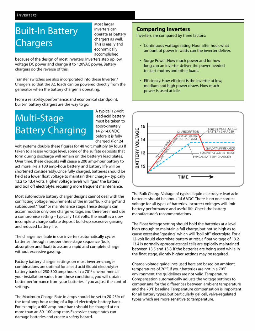
A typical 12-voltlead-acid batterymust be taken toapproximately14.2-14.6 VDCbefore it is fullycharged. (For 24
volt systems double these figures for 48 volt, multiply by four.) Iftaken to a lesser voltage level, some of the sulfate deposits thatform during discharge will remain on the battery’s lead plates.Over time, these deposits will cause a 200 amp-hour battery toact more like a 100 amp-hour battery, and battery life will beshortened considerably. Once fully charged, batteries should beheld at a lower float voltage to maintain their charge – typically13.2 to 13.4 volts. Higher voltage levels will "gas" the batteryand boil off electrolyte, requiring more frequent maintenance.
Most automotive battery charger designs cannot deal with theconflicting voltage requirements of the initial “bulk charge” andsubsequent “float” or maintenance stage. These designs canaccommodate only one charge voltage, and therefore must usea compromise setting – typically 13.8 volts. The result is a slowincomplete charge, sulfate deposit build-up, excessive gassingand reduced battery life.
The charger available in our inverters automatically cyclesbatteries through a proper three stage sequence (bulk,absorption and float) to assure a rapid and complete chargewithout excessive gassing.
Factory battery charger settings on most inverter-chargercombinations are optimal for a lead acid (liquid electrolyte)battery bank of 250-300 amp hours in a 70°F environment. Ifyour installation varies from these conditions, you will obtainbetter performance from your batteries if you adjust the controlsettings.
The Maximum Charge Rate in amps should be set to 20-25% ofthe total amp-hour rating of a liquid electrolyte battery bank.For example, a 400 amp-hour bank should be charged at nomore than an 80 -100 amp rate. Excessive charge rates candamage batteries and create a safety hazard.
The Bulk Charge Voltage of typical liquid electrolyte lead acidbatteries should be about 14.6 VDC. There is no one correctvoltage for all types of batteries. Incorrect voltages will limitbattery performance and useful life. Check the batterymanufacturer’s recommendations.
The Float Voltage setting should hold the batteries at a levelhigh enough to maintain a full charge, but not so high as tocause excessive "gassing" which will "boil off" electrolyte. For a12-volt liquid electrolyte battery at rest, a float voltage of 13.2-13.4 is normally appropriate; gel cells are typically maintainedbetween 13.5 and 13.8. If the batteries are being used while inthe float stage, slightly higher settings may be required.
Charge voltage guidelines used here are based on ambienttemperatures of 70°F. If your batteries are not in a 70°Fenvironment, the guidelines are not valid. TemperatureCompensation automatically adjusts the voltage settings tocompensate for the differences between ambient temperatureand the 70°F baseline. Temperature compensation is importantfor all battery types, but particularly gel cell, valve-regulatedtypes which are more sensitive to temperature.
Built-In BatteryChargers
Multi-StageBattery Charging

Smooth Start Series
User Instructions for Model STP-1000T Power Inverter
Model STP-1000T

Safety Information
IMPORTANT Read all the Cautions and Warnings before installing and using the power inverter. The
inverter must be properly installed.
IMPORTANT If you are not familiar with 12 volt high current wiring, it is recommended that you have a
professional automotive installer install the inverter.
CAUTION The power inverter generates 115 VAC power from your 12 volt car battery. Treat the 115
VAC output just like you treat the 115 VAC in your house. Keep children away from the unit.
Do not connect the unit to AC distribution wiring. Keep the unit away from water. Do not allow water to drip or splash on to the power inverter. Keep the unit in cool environments. Ambient air temperature should be between 32 degrees and
75 degrees F. Keep out of direct sunlight and away from heating vents. Keep the unit away from flammable material or in any location which may accumulate flammable
fumes or gases, such as the battery compartment of your car, boat, RV or truck. With heavy use, the unit will become warm and possibly hot. So keep it away from any heat
sensitive materials. Make sure the opening to the fan and vent holes are not blocked. Do not open the unit. High voltages are inside. Use proper size wiring. High power inverters can draw many amps from the 12 volt source and
can melt wires if not fused and sized properly.
IMPORTANT Sima Products Corporation does not authorize any products to be used in life support
devices or systems. Serial # ____________________________ Date Purchased ___________
page 2

Table of Contents
Safety Information ...................................................................................................2 Introduction..............................................................................................................4 Key Features ............................................................................................................4 Package Includes......................................................................................................4 Needed for Installation (not included) .....................................................................4 Overview of the Power Inverter...............................................................................5 Installation ...............................................................................................................6
Installation Overview ....................................................................................................................6 Step #1: Mounting the Inverter .....................................................................................................6 Step #2: Wiring Inverter to 12 volt Power ....................................................................................7
Permanent Installation...............................................................................................................8 Wiring Steps..............................................................................................................................8 Advanced Installation................................................................................................................9
Step #3: Testing the Power Inverter ..............................................................................................9 Operation .................................................................................................................9
Equipment Power Usage ...............................................................................................................9 Battery Life .................................................................................................................................10 Lights and Alarms .......................................................................................................................11
How the Inverter Works.........................................................................................12 Troubleshooting .....................................................................................................13 Product Specifications ...........................................................................................14 Warranty ................................................................................................................15
page 3

Introduction Congratulations on your purchase of a Sima Products Corporation power inverter. It provides 115 VAC anywhere you have 12 DC volts in your car, truck, RV or boat. It is designed to be easy to use and provide years of dependable service.
Key Features High-efficiency operation to provide the most output with the least battery power. Advanced protection
• Thermal Protection shuts the unit off to guard against the unit getting too hot • Overload Protection protects the unit from excessive loads • Under Voltage Protection turns the unit off to protect the battery from being over
discharged The STP-1000T power inverter produces a modified sine wave output that is suitable for most AC loads. This includes lights, appliances, motors, TVs and most electronics.
Caution: A few battery chargers are not compatible with modified sine wave operation. These are typically small, rechargeable, battery operated devices like razors and flashlights that can be plugged directly into an AC receptacle to recharge. Some chargers for battery packs used in power tools also should not be used with an inverter. These chargers typically have a warning label indicating that dangerous voltages are present at the battery terminals. Only a true sine wave inverter should be used with these types of appliances. Damage to the device could result if you attempt to use them with any type of modified sine wave inverter. Do not use this power inverter with the above devices.
Package Includes Inverter (STP-1000T) Cables This manual
Needed for Installation (not included) Mounting hardware for the inverter 12 volt DC power wiring, fuse block and connectors Tools – Drill and drill bit, small socket set, wire crimpers, volt meter Optional: wiring kit from Sima Model SK-200
page 4

Overview of the Power Inverter The STP-1000T power inverters are electronic devices that convert the low voltage 12 VOLTS DC from a battery or other power source to 115 VAC to run standard household appliances. See the section on How it Works to learn more about the technology used in these power inverters.
DC Side (12 VOLTS Input) AC Side (115 VAC Output) STP-1000
Figure #1, DC and AC Sides of the STP-1000T Inverter
page 5
Installation
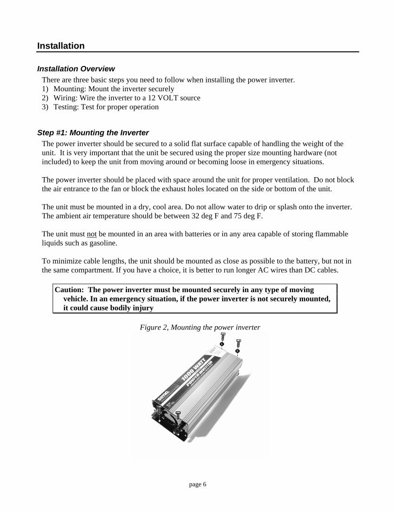
Installation Overview There are three basic steps you need to follow when installing the power inverter. 1) Mounting: Mount the inverter securely 2) Wiring: Wire the inverter to a 12 VOLT source 3) Testing: Test for proper operation
Step #1: Mounting the Inverter The power inverter should be secured to a solid flat surface capable of handling the weight of the unit. It is very important that the unit be secured using the proper size mounting hardware (not included) to keep the unit from moving around or becoming loose in emergency situations. The power inverter should be placed with space around the unit for proper ventilation. Do not block the air entrance to the fan or block the exhaust holes located on the side or bottom of the unit. The unit must be mounted in a dry, cool area. Do not allow water to drip or splash onto the inverter. The ambient air temperature should be between 32 deg F and 75 deg F. The unit must not be mounted in an area with batteries or in any area capable of storing flammable liquids such as gasoline. To minimize cable lengths, the unit should be mounted as close as possible to the battery, but not in the same compartment. If you have a choice, it is better to run longer AC wires than DC cables.
Caution: The power inverter must be mounted securely in any type of moving vehicle. In an emergency situation, if the power inverter is not securely mounted, it could cause bodily injury
Figure 2, Mounting the power inverter
page 6

Step #2: Wiring Inverter to 12 volt Power The power inverter requires connection to a standard 12 volt DC power source as found in most cars, trucks, RVs and boats. The power source must provide between 11 and 15 volts DC. The power source must be able to provide sufficient current to power the load. See the chart below that shows minimal wire sizing and current draw at full load.
Inverter Model Current at rated power
Suggested User Installed 12 volt Fuse Size
Suggested Wire gauge, less than-10’
Suggested Wire gauge, 10’ to 25’
STP-1000T 94 Amps 100A 2 AWG 0 AWG
Wire Size Chart Always connect the positive, red (+) terminal to the positive connection and the negative, black (-) terminal to the negative or ground side of the power system.
WARNING Failure to connect the correct polarity may cause damage to the power inverter
and/or your electrical system and is not covered by the warranty.
Installation Tip To minimize electrical interference, keep the DC power cables as short as possible
and twist them with 1 to 3 twists per foot. This minimizes radiated interference from the cables.
page 7

Permanent Installation Figure 3, Wiring the STP-1000T power inverter
Caution: Always use adequate wire size and fusing for any installation
Wiring Steps • Disconnect the positive battery terminal before doing any wiring to the inverter. • Using proper sized copper wire and proper terminations, wire the inverter to the electrical
system and fuse block. See your local RV dealer or automotive shop for wire, connectors, fuse block and other wiring parts. Tighten all connections firmly, but do not over tighten. Remember to recheck all connections every few months of operation.
WARNING Do not operate the power inverter without a fuse installed.
page 8
• Double check all wiring for proper polarity. • Install the fuse and reconnect the wire to the battery. Note, a slight spark and beep from the
inverter is normal when the unit is first connected to 12 volt power.
Advanced Installation Large inverters can draw high currents from your battery and charging system especially when used with appliances and tools that use a lot of power. In these applications, you may need to increase the capacity of your 12 volt system. There are several ways to do this.
High Capacity Batteries You can purchase high capacity batteries that are specially designed for deep discharge operation. Contact your automotive or RV specialist for more information. Multiple Batteries In systems with more than one battery, you typically wire the system with the batteries in parallel (negative to negative and positive to positive) with a battery isolator between the positive terminals. The isolator allows a single alternator to charge all batteries but lets the inverter only use the second battery so the vehicle’s battery is not discharged during operation. Contact your automotive or RV specialist for more information about battery isolators and wiring. Larger Alternator Typical automotive alternators may not be able to supply the power required for continuous operation of the inverter at high power usage. Contact your automotive or RV specialist for more information about larger output alternators.
Step #3: Testing the Power Inverter After you make sure the 12 volt power is wired properly to the power inverter, with nothing plugged into the 115 VAC outlets, turn the power switch on the power inverter to On. The green POWER light will light. Note: If the inverter does not operate properly and the POWER light does not illuminate, turn the power switch off and check your wiring and external fuse. With the inverter turned off, plug the appliance you want to use into the 115 VAC power outlet on the unit. Turn the power switch on the power inverter on so the green POWER light is illuminated. Turn on the appliance. The appliance should now be operational. Check the Troubleshooting section if you have any difficulties.
Operation
Equipment Power Usage It is important to use only products that draw less than the power rating of the power inverter. Use of products greater than the rated power rating may either cause the protection circuitry of the power
page 9

inverter to shut down or the fuse to blow. Repeated use of excessive power draw can cause failure of the power inverter. How to calculate power usage. Most products have a power rating on them such as 45 watts. Others may be marked with their current draw, such as .9 amps. To convert the current to watts multiply the current by 115. (Example: .9 amps x 115 = 104 watts)
Typical Power Usage Chart Typical Appliance Current Draw TV/VCR combo 120 watts 19” TV 160 watts Blender 650 watts Small power drill 3/8” 500 watts Toaster 850 watts Vacuum 900
Some products draw a high surge current to start up. If the appliance does not operate and the inverter turns off, you may need a larger inverter. Also, check that the battery and the 12 volt wiring to the inverter is large enough to handle the current draw and that the battery is fully charged.
Important: The power inverters may not operate some appliances designed to produce heat such as hair dryers, heaters, toasters and coffee makers. Always check the power rating before using these kinds of products to be sure they do not exceed the power capability of the inverter.
Battery Life Important: The power inverter can draw lots of amps from your car’s battery when operating. If you are using it for extended periods of time, you will want to operate your car occasionally to maintain the charge in your car’s battery. In addition, the power inverter will also draw a small current, less than 0.1 amp, when turned off and not operating. Therefore, it should be disconnected from your car’s battery if your vehicle will not be used for more than a day. The following chart shows typical operation time for typical car batteries with the engine not running for various loads. Check the size of your battery.
page 10

Battery Life Chart Power Usage
Approximate 12 volt Current
Typical operation time with 50 amp-hour car battery
Typical operation time with 100 amp-hour car battery
100 watt 9 Amps 5.5 hours 11 hours 200 watt 19 Amps 2.6 hours 5.2 hours 500 watt 47 Amps 1 hour 2 hours
Actual Current Draw Approximate 12 volt current draw is the load in watts divided by 10. Thus a 60 watt light bulb plugged into the inverter will cause the inverter to draw 6 amps (60 / 10 = 6) from the 12 volt supply. Batteries are rated in several different ways:
Peak cranking amps - This has little to do with how long an inverter can supply power, so it is not a useful number for inverter operation.
Battery reserve capacity - This number shows how long a battery can supply a given current, typically 25 amps, before the battery voltage reaches a low voltage. Therefore, a battery rated at 200 minutes reserve can deliver 25 amps for 200 minutes before it is discharged.
Ampere-hour capacity - This rating indicates how many amps a battery can deliver over a period of time, typically 20 hours. Therefore, a 100 amp-hour battery can deliver 5 amps for 20 hours (5 x 20 = 100).
Actual operating time from a battery will depend upon the current draw from the battery. A
battery will deliver less total power (energy) as you draw higher amps. A 100 amp-hour battery can deliver 5 amps for 20 hours (100 amp-hours) but it will only deliver 50 amps for 1 ½ hours (50 x 1.5 = 75) or 75 amp-hours at the higher rate.
Also remember, battery life is decreased if the battery is discharged fully. Lead acid batteries have the longest life, if they are kept fully charged.
Lights and Alarms POWER Indicator (Green) This light will illuminate when the inverter is turned on and is operating normally. If this light goes out the 12 volt power is missing (possible blown fuse). These fault conditions include output overload, output short circuit, low input voltage and over temperature of the unit. This can happen if a device has a large turn on surge, if an appliance (like a drill or saw) is stalled or if the inverter does not have a supply of cool air.
Fault Indicator (Red) Fault conditions include output overload, output short circuit, low input voltage and over temperature of the unit. This can happen if a device has a large turn on surge, if an appliance (like a drill or saw) is stalled or if the inverter does not have a supply of cool air.
Fuse Replacement If you overload the power inverter, it is possible that the external fuse might blow. Always determine the cause of the fuse blowing and remedy the problem before using the power inverter again.
page 11

How the Inverter Works
The Sima Products Corporation power inverter has two electronic sections. The first section converts 12 volts DC to approximately 160 volts DC using modern high frequency conversion techniques that uses small lightweight efficient transformers. The second section converts the 160 volts DC to 115 VAC using high efficiency power MOSFET transistor devices. The inverters generate a modified sine wave that works with almost every product on the market.
CAUTION: Do not use the following products with an inverter with a modified sine wave output.
Small battery operated devices like razors, flashlights and night lights that can be plugged directly into an AC outlet to recharge
A few battery chargers for power tool battery packs that have warnings about high voltage present on the battery terminals.
Smooth Start The Smooth Start feature of the STP line of power inverters is designed to handle the power surge that is created when some appliances are turned on. This feature helps protect both the appliance and the inverter from excessive power draws and surges. When the power switch is turned on, the STP inverter smoothly brings up the AC power. This circuitry also activates under excessive loads, even short circuits, to quickly turn off power to protect the device and the inverter. The STP inverter then attempts to smoothly bring up the AC power, unless it detects an excessive load.
page 12

Troubleshooting
Problem Cause Solution Unit does not operate Input voltage is below
10 volts Attach to proper supply
Fuse blown Determine cause for fuse blowing and then replace fuse feeding inverter.
Unit operates for a short period and then turns off
Load is trying to draw too much current
Be sure load is less than rated watts of inverter. Remove excessive load. Turn inverter off and back on to reset.
Unit operates for a while and gets warm
Inverter is in thermal shutdown mode
Allow inverter to cool down. Turn inverter off and back on to reset.
Low battery alarm is on
Input voltage is below 10.2 volts
Make sure car engine is running. Check condition of wiring. Battery may be low and needs
recharging. Television and stereo
interference RF interference from
power inverter Position the power inverter and
wiring as far as possible from electronic equipment, antenna and cables and reorient as necessary.
115 VAC Output
voltage reads incorrectly
Modified sine wave output can cause incorrect reading on a typical multimeter
Use a true RMS meter like a Fluke 8060A or Triplett 4200 to measure correct voltage.
Light Status Chart
Power Switch
Power Light
Beeper Fan Fault Light Mode
Off Off Off Off Off Unit is off On On Off On Off Normal Operation On On On On Off Low input voltage, 10.2 to 9.7 volts On On On On On Low input voltage, less than 9.7 volts On On Off On On High Input voltage, greater than 15V On On Off On On Unit over temperature or overloaded On Off Off Off Off No 12 VOLTS input to inverter
page 13
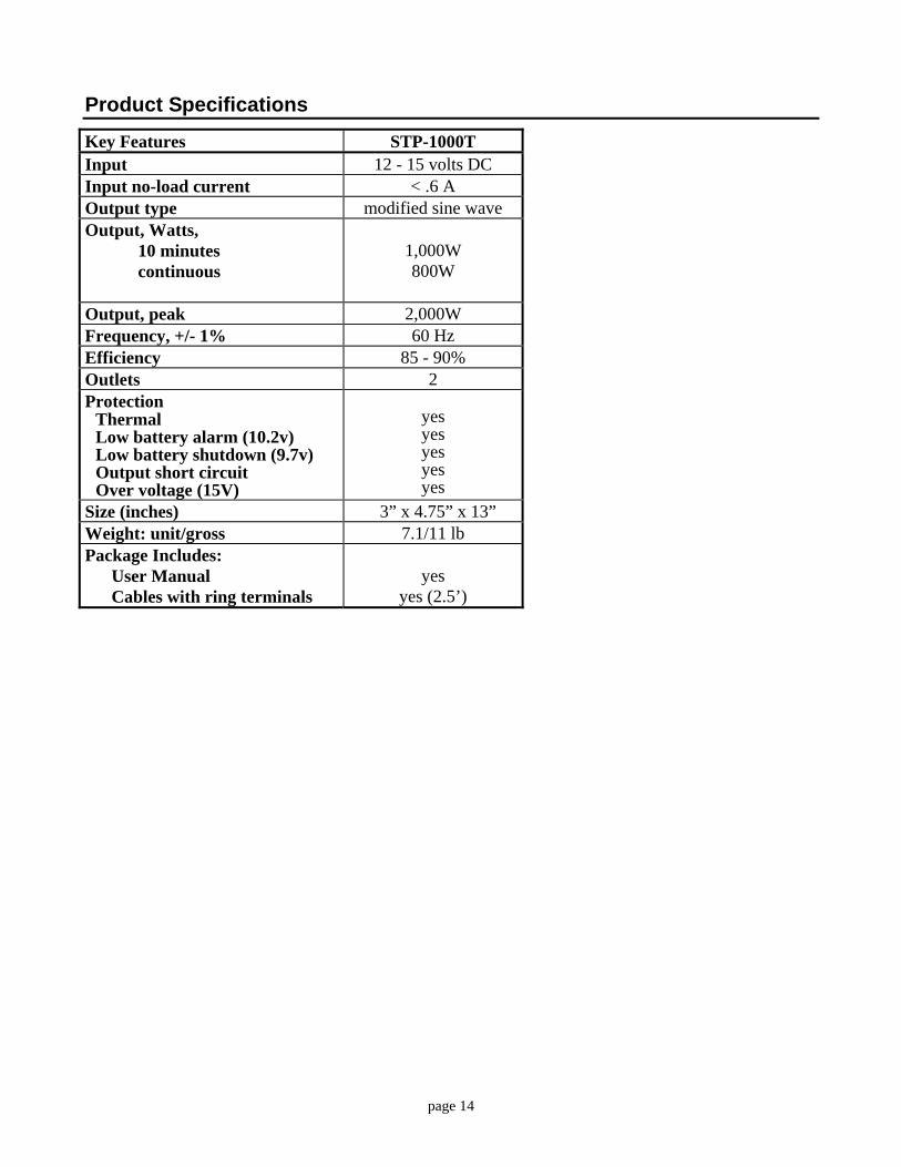
Product Specifications
Key Features STP-1000T Input 12 - 15 volts DC Input no-load current < .6 A Output type modified sine wave Output, Watts, 10 minutes continuous
1,000W 800W
Output, peak 2,000W Frequency, +/- 1% 60 Hz Efficiency 85 - 90% Outlets 2 Protection
Thermal Low battery alarm (10.2v) Low battery shutdown (9.7v) Output short circuit Over voltage (15V)
yes yes yes yes yes
Size (inches) 3” x 4.75” x 13” Weight: unit/gross 7.1/11 lb Package Includes: User Manual Cables with ring terminals
yes
yes (2.5’)
page 14

Limited Warranty Sima Products Corporation (“Company”) warrants that if the accompanying product proves to be defective to the original purchaser in material or workmanship within 90 days from the original retail purchase, the Company will, at the Company’s option, either repair or replace same without charge (but no cash refund will be made). If the product is returned within three (3) years from the original date of purchase, the Company will repair or replace the unit, however, a standardized labor-only fee will be charged. The Company will not charge a fee for any parts used in the repair. The Company will notify you of any fees to be assessed prior to servicing the unit. What you must do to enforce the Warranty: You must deliver, mail or ship the product, together with the original bill of sale, this limited Warranty statement as proof of warranty coverage to: Sima Products Corporation Attn: Customer Service 140 Pennsylvania Ave., Bldg. #5, Oakmont, PA 15139 Call customer service (800-345-7462) before sending the unit in for service.
Limitation of Liability and Remedies
Sima Products Corporation shall have no liability for any damages due to lost profits, loss of use or anticipated benefits, or other incidental, consequential, special or punitive damages arising from the use of, or the inability to use, this product, whether arising out of contract, negligence, tort or under any warranty, even if Sima Products Corporation has been advised of the possibility of such damages. Sima Products Corporation’s liability for damages in no event shall exceed the amount paid for this product. Sima Products Corporation neither assumes nor authorizes anyone to assume for it any other liabilities. Sima Products Corporation 140 Pennsylvania Ave Bldg #5 Oakmont, PA 15139 USA
800-345-7462 Sima Products Corporation ©2003 P/N #21687
page 15

TN/TS-1500
Inverter Instruction Manual

Index
TN/TS-1500 Instruction ManualInverter
1. Safety Guidelines 1
1
2
2
3
3
5
9
12
14
17
17
12
13
4
3
4
5
6
8
9
9
10
12
2. Introduction
3. User Interface
4. Explanation of Operating Logic
5. Initial Setup of TN/TS-1500
6. Protection
7. Installation & Wiring
8. Failure Correction Notes
9. Warranty
2.1 Features
3.2 LED Indicator on Front Panel
3.1 Front Panel
2.2 Main Specification
2.3 System Block Diagram
3.3 Functional Indication andAlarm
3.4 Rear Panel
4.1 Explanation of UPS Mode Control Logic
4.2 Explanation of Energy Saving Mode Control Logic
5.1 Initia l State
5.2 Initia l Set Point for Transition Voltages
5.3 Procedure of Setting Operating Mode, Output Voltage,
5.4 Remote Monitoring Software
Frequency, and Saving Mode
6.1 Input Protection
6.2 Output Protection
...............................................................................
........................................................................................
........................................................................................
........................................................................
..................................................................
......................................................................................
....................................................................................
......................................................
................................................
....................................................................................
..................................................................................
...............................................................
......................................................
.......................................................
...........................................................................................
...........................................................................
........................................................................
..........................................................................
...................................................................
.............................................................................................
.....................................
........................................................
....................................
...................
Feb. 2013 Version 13
Inverter InverterInverter Inverter
1
Don'tdisassemble
Away frommoistu re
Away from fire orh igh temperature
Don't stack onthe inverter
Keep goodventilation
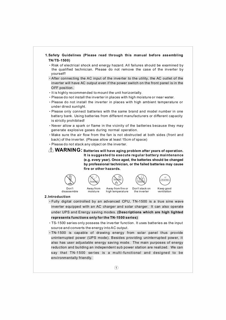
1.Safety Guidelines (Please read through this manual before assembling
TN/TS-1500)
‧Risk of electrical shock and energy hazard. All failures should be examined bythe qualified technician. Please do not remove the case of the inverter by
‧After connecting the AC input of the inverter to the utility, the AC out let of the
‧It is highly recommended to mount the unit hor izontally.
‧Please do not install the inverter in places with high moisture or near water.
‧Please do not instal l the inverter in places with high ambient temperature or
‧Please only connect batteries with the same brand and model number in one
‧Never allow a spark or f lame in the vicinity of the batteries because they may
‧Make sure the air flow from the fan is not obstructed at both sides (front and
‧Please do not stack any object on the inverter.
‧Fully digital controlled by an advanced CPU, TN-1500 is a true sine wave
‧TS-1500 series only possess the inverter function. It uses batteries as the input
‧TN-1500 is capable of drawing energy from solar panel thus provide
yourself!
inverter will have AC output even if the power switch on the front panel is in the
OFF position .
under direct sunlight.
battery bank. Using batteries from different manufacturers or different capacity
generate explosive gases during normal operation.
back) of the inverter. (Please allow at least 15cm of space)
inverter equipped with an AC charger and solar charger. It can also operate
source and converts the energy intoAC output.
uninterrupted power (UPS mode). Besides providing uninterrupted power, i t
also has user adjustable energy saving mode. The main purposes of energy
reduction and building an independent sub power stat ion are realized. We can
say tha t TN-1500 se r ies is a mult i - funct iona l and designed to be
environmentally friendly.
under UPS and Energy saving modes. (Descriptions which are high lighted
represents functions only for the TN-1500 series)
is str ictly prohibited!
2.Introduction
WARNING:It is suggested to execute regular battery maintenance
Batteries will have aging problem after years of operation.
(e.g. every year). Once aged, the batteries should be changed
by professional technician, or the failed batteries may cause
fire or other hazards.

2.2 Main Specification
2.1 Features
‧True sine wave output (THD<3%)
‧Selectable UPS or Energy saving mode
‧1500W rated output
‧High effic iency up to 90%
‧Complete LED indication for operating status
‧Battery low alarm and indicator
‧Surge power capability up to 3000W
‧Output vo ltage / frequency selectable
‧Fully digi tal controlled
‧Compliance to UL458 / FCC / E / CE13
‧Can be used for most of electronic products with AC input
‧3 year global warranty
‧Solar charging current 30A max
‧Fast transfer time 10ms (Typ.)
1500W max. continuously, 1750W max. for 180 seconds, 1875Wmax. for 10 seconds,3000W for 30 cycle
INPUT
CHARGER
BAT. VOLTAGE
DC CURRENT
EFFICIENCY
OFF MODECURRENTDRAW
PROTECTION
CHARGEVOLTAGEAC CHARGECURRENTSOLAR OPENCIRCUITVOLTAGE
CHARGESOLAR
10.5 ~ 15.0V
150A
87%
14.5V
5.5A 0.5A±
25Vmax
30A max.
Under 1.0mA at power switch OFF
21.0 ~ 30.0V
75A
89%
29.0V
2.7A 0.4A±
45Vmax
42.0 ~ 60.0V
37.5A
58.0V
1.35A 0.2A±
75Vmax
10.5 ~ 15.0V
150A
88%
14.5V
5.5A 0.5A±
25Vmax
21.0 ~ 30.0V
75A
90%
29.0V
2.7A 0.4A±
45Vmax
42.0 ~ 60.0V
37.5A
91%
58.0V
1.35A 0.2A±
75Vmax
MODEL
Ratedpower
Output vol tage
Frequency
SurgeCurrentFactoryset ting
WAVEFORM
OUTPUT
PROTECTION
112 124 148 212 224 248
110V 60Hz
100 / 110 / 115 / 120V
True s ine wave (THD <3.0%)
AC short Overload Over Temperature、 、
230V 50Hz
200 / 220 / 230 / 240V
Over current battery polarity reverse by fuse battery low shutdown battery low alarm、 、 、
CURRENT
2
‧TN-1500 series will automatically detect the input sources (whether AC main or
‧With pure sine wave output, TN/TS-1500 can provide 1500W cont inuously,
solar panels exist) and then adjust its internal setting. Users can also set up the
operating mode, output voltage, frequency, and saving mode by themselves
based on their special needs, geographic area, and environmental conditions.
1750W for 3 minutes, or 20~40A of peak current for all kinds of load such as
inductive, capacitive, or resistive. General applications include PC, ITE,
vehicles, yachts , home appliances, motors, power tools, industrial control
equipments, AV system, and etc.. .
89%
60 0.1Hz± 50 0.1Hz±

3
2.3 System Block Diagram
Figure 2.1 System Block Diagram
TN-1500 Inverter
ACInput
ACOutput
AC charger
Solar charger
Battery
Fuse
Fuse
12V/24V/48VDC/DC
Converter
Solar Panel
EMIfi l ter
200V DC
CPUControll er
Polari tydetect
DC/ACInverte r
LOAD
120V/230V
Circui tBreaker
50Hz/60Hz/400VDC
LEDDisplay
A
B
C
D
E
F
G
3.1 Front Panel
POWER on/off switch: The inverter will turn OFF if the switch is in the OFF
AC output outlet: To satisfy application demand of d ifferent geographic areas
No Fuse Breaker; Reset: Under "Bypass Mode", when the AC output is
Ventilation holes: The inverter requires suitable ventilation to work properly.
Function Setting: Operating Mode, Output vo ltage, frequency, and saving
LED Indicating Panel: Operating status, load condit ion, and all types of
Communication Port: For remote monitoring purpose, the unit can be
position.
all over the world, there are many optional AC outlets to choose from.
shorted or the load current exceeds the rated current of the No Fuse Breaker,
Please make sure there is good ventilat ion and the l ifespan of the inverter can
mode can be set through this button.
warnings will be displayed on this panel.
connected to a PC through this communication port by using the optional cable
and monitoring software.
preserved.
the No Fuse Breaker wi ll open and that stops bypassing energy from the utility
getting to prevent poss ible danger. When the abnormal operating condit ion is
removed, user can press down on the Reset button to resume operation.
3.User interface

4
3.2 LED Indicator on Front Panel
3.3 Function Indication and Alarm
LED 1 ON
LED 1 ON
LED 1~ 2 ON
LED 1~ 2 ON
LED 1 ~ 3 ON
LED 1 ~ 3 ON
LED 1 ~ 4 ON
LED 1 ~ 4 ON
BatteryCapacity
BatteryCapacity
LED Display
LED Display
0 ~ 25% 26 ~ 50% 51 ~ 75% 76 ~ 100%
AC OUTPUTSOLAR CHARGE
AC CHARGE
B F
A
C
BATTERY100
0
1 00
0
Saving
Ba t Low
On
Se ttin gLOA D
INV ERTER
BY PAS SAC I N
E
G
Figure 3.1: Front Panel (TN-1500)
D
ON
OFF
Remoteport
0 ~ 30% 30 ~ 50% 50 ~ 75% 75 ~ 100%
Battery Capacity Indicator: represents the remaining capacity of external
◎On : The inverter started up and output is normal.
◎ Bat Low : Voltage of external batteries is too low. The inverter will send out
◎ Saving : The inverter is operating under the "Saving Mode" and there's no
a "Beep" sound to warn the users.
AC output.
batteries.
Load Condition Ind icator: represents the magnitude of output loads.
◎AC CHARGE : The built- in AC charger is charging external batteries.
◎ SOLAR CHARGE : The external solar panels are provid ing energy to the
◎ AC IN: The status of utility is normal.
◎ BYPASS: The unit is working under "Bypass Mode". The AC electricity
◎ INVERTER: The unit is working under "Inverter Mode" The AC electricity
◎BATTERY: Display the remain ing capacity of external batteries.
◎LOAD: Display the output load status.
external batteries through the built-in solar charger.
consumed by the loads is provided by the utility instead of the inverter.
consumed by the loads is converted from the batteries .

3.4 Rear Panel
Battery input (+), (-) .
Uti lity / AC inlet (IEC320).
Solar panel input terminal.
Frame ground (FG).
A
B
C
D
Fig 3.2: Rear Panel (TN-1500)
5
4.Explanation of Operating Logic
TN-1500 (CPU control led inverter) is des igned to achieve the goal of energy
saving and possesses both UPS and Energy saving modes. These 2 modes are
user adjustable. The unit will be factory set in the UPS mode. Depending on
weather and util ity conditions, users can manually adjust or use the monitoring
software to switch to the Energy sav ing mode.
The main difference between UPS and Energy saving mode is the amount of
energy conserved. Under the UPS mode, the unit will remain in the Bypass mode
as long as utili ty is available. Thus less energy is conserved (refer to Fig. 4.1 for
UPS mode control logic). Under the Energy saving mode, the priority of input
source chosen is solar panel AC main battery. If available, the CPU will select
external solar panels as its first priority in order to conserve energy. In case of
insufficient solar power and uti lity failure, battery power will be drawn as the last
resort. When the capacity of batteries is around 10~20%, the CPU will remind
end users by continuously sending out warning siren unt il the system shuts down.
BA
D
C
AC INPUT
Chassis
Ground
Reverse PolarityWill Damage The
Uni t.
Solar Input(30A max)
NEG POS
DC
INPUT
Cat .No.(1GG1HS-212 )Wire Ran ge(10-4AWG StrCu So ldered Wires )Torque ( 17.7 -26.5 in lb)
6
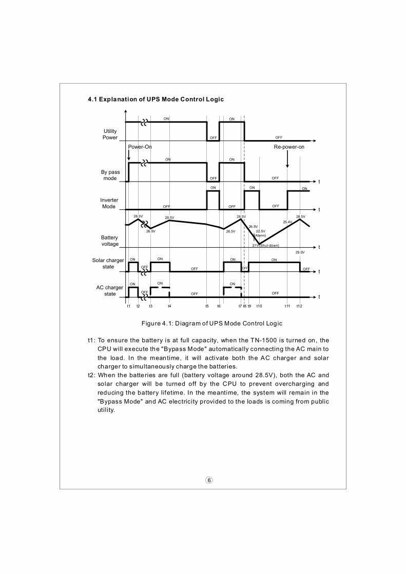
4.1 Explanation of UPS Mode Control Logic
ON
28.5V
26.5V
28.5V 28.5V
ON
OFF
ONON
By passmode
InverterMode
Batteryvoltage
ON
OFF
Solar chargerstate
AC chargerstate
ON
OFF
ON
OFF
OFF
26.5V
28.5V
OFF
ON
29.0V
ON
OFF
OFF
ON
Power-On Re-power-on
21V(Shut-down)
t
t
t
t
t
UtilityPower
ON
OFF
22.5V(Alarm)
ON
OFF
OFF
OFF
ON
OFF
ON
OFF
25.4V
t1 t2 t3 t4 t5 t6 t8 t9 t10 t11 t12t7
26.5V
Figure 4.1: Diagram of UPS Mode Control Logic
t1: To ensure the battery is at full capacity, when the TN-1500 is turned on, the
t2: When the batteries are full (battery voltage around 28.5V), both the AC and
CPU will execute the "Bypass Mode" automatically connecting the AC main to
the load. In the meantime, it will activate both the AC charger and solar
solar charger will be turned off by the CPU to prevent overcharging and
reducing the battery lifetime. In the meantime, the system will remain in the
"Bypass Mode" and AC electricity provided to the loads is coming from public
utility.
charger to simultaneously charge the batteries.

7
t3: At this time period, TN-1500 is still in the Bypass mode. The battery voltage
t4: If the energy provided by the charger is larger than what is consumed by the
t5: Since the chargers are in the OFF mode, the battery voltage will gradually
t6: Once utility recovers, the CPU will switch back to the bypass mode.
t7: When battery voltage drops to below 26.5V, the battery charger will be
t8: Same as t4.
t9: Due to lack of utility, TN-1500 will switch to the inverter mode. AC charging
t10: As the battery discharges to below 26.5V and ut ility remains unavai lable.
t11: Same as Energy Saving mode.
t12: When solar charger is providing current of larger than 3A, the vo ltage level of
level will decrease gradually due to standby power dissipation. When the
batteries are consumed to around 75% of their capacity (battery voltage
around 26.5V) the CPU will restart the charger. The CPU will use charging
current of 3A as a guide point. When the provided charging current is under
3A, the AC charger wil l be turned ON (e.g. Night time or cloudy day). As for
load, voltage of battery bank will increase gradual ly until 28.5V is reached
then the CPU will be shut off the charger to prevent overcharging. At this
decrease to the range of 26.5~28.5V (floating voltage level). If utility were to
fail at this moment, the CPU will automatically switch (<10ms) to the inverter
mode insuring uninterrupted power.
activated to charge the battery bank (refer to t3 for detailed description).
function wi ll be turned off. Since AC output relies purely on battery power, the
Only the solar charger is turned ON. The battery bank could be depleted
rather quickly.
the battery bank will r ise slowly. Once the battery vol tage reaches inverter
mode reactivation level, the inverter wi ll be revived.
battery bank wi ll be depleted rather quickly.
charging current of over 3A, the solar charger wi ll be turned ON instead.
point, output load is stil l supplied by utili ty.
4.2 Explanation of Energy Saving Mode Control Logic
ON
OFF
28.5V
26.5V
28.5V
22V
28.5V
ON
OFF
ONON
OFF
Bypassmode
Invertermode
Batteryvoltage
ON
OFF
Solar chargerstate
ON
26.5V
ON ON
OFF
OFF
26.5V
28.5V
OFF
ON
ON
OFFOFF
ON
21.0V (Sh ut-down)
t
t
t
t
Uti lityPower
Power-On
ON
OFF
22.5V(Alarm) 22.5V
(Alarm)
AC chargerstate
t1 t2 t3 t4 t5 t6 t7 t8
OFF OFFt
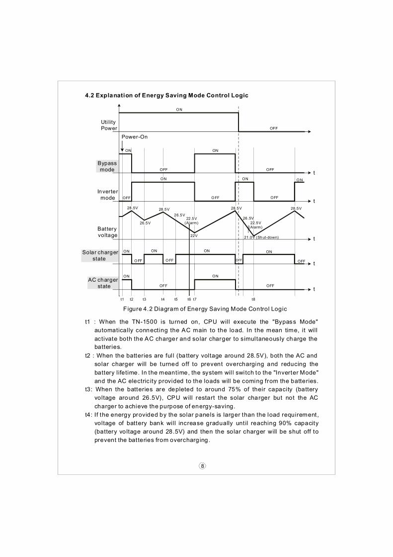
F igure 4.2 Diagram of Energy Saving Mode Control Logic
8
t1 : When the TN-1500 is turned on, CPU will execute the "Bypass Mode"
t2 : When the batteries are ful l (battery voltage around 28.5V), both the AC and
t3: When the batteries are depleted to around 75% of their capacity (battery
t4: If the energy provided by the solar panels is larger than the load requirement,
automatically connecting the AC main to the load. In the mean time, it will
activate both the AC charger and solar charger to simultaneously charge the
solar charger will be turned off to prevent overcharging and reducing the
battery lifetime. In the meantime, the system wil l switch to the "Inverter Mode"
and the AC electric ity provided to the loads will be coming from the batteries.
voltage around 26.5V), CPU will restart the solar charger but not the AC
voltage of battery bank will increase gradually unt il reaching 90% capacity
(battery vo ltage around 28.5V) and then the solar charger will be shut off to
charger to achieve the purpose of energy-saving.
prevent the batteries from overcharg ing.
batteries.
9
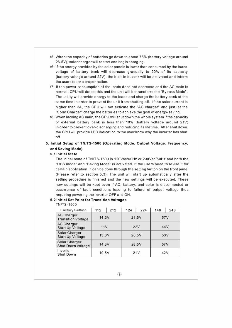
Factory Setting
AC ChargerTransit ion Voltage
AC ChargerStart Up Voltage
Solar ChargerStart Up Voltage
112 212 124 224 148 248
14.3V
11V
13.3V
28.5V
22V
26.5V
57V
44V
53V
Solar ChargerShut Down Voltage
Inver terShut Down
14.3V
10.5V
28.5V
21V
57V
42V
t5: When the capacity of batteries go down to about 75% (battery voltage around
t6: If the energy provided by the solar panels is lower than consumed by the loads,
t7: If the power consumption of the loads does not decrease and the AC main is
t8: When lacking AC main, the CPU will shut down the whole system if the capacity
26.5V), solar charger will restart and begin charg ing.
the users to take proper act ion.
"Solar Charger" charge the batteries to achieve the goal of energy-saving.
the CPU will provide LED indication to the user know why the inverter has shut
off .
requiring powering the inverter OFF and ON.
voltage of battery bank will decrease gradually to 20% of its capacity
(battery voltage around 22V), the built-in buzzer will be activated and inform
normal, CPU will detect this and the unit will be transferred to "Bypass Mode".
The ut ility will provide energy to the loads and charge the battery bank at the
same time in order to prevent the unit from shutting off. If the solar current is
higher than 3A, the CPU will not activate the "AC charger" and just let the
of external battery bank is less than 10% (battery voltage around 21V)
in order to prevent over-discharging and reducing its lifetime. After shut down,
5. Initial Setup of TN/TS-1500 (Operating Mode, Output Voltage, Frequency,
and Saving Mode)
TN/TS-1500
5.1 Initial State
5.2 Initial Set Point for Transition Voltages
The ini tial state of TN/TS-1500 is 120Vac/60Hz or 230Vac/50Hz and both the
"UPS mode" and "Saving Mode" is activated. If the users need to revise it for
certain application, it can be done through the setting button on the front panel
(Please refer to section 5.3). The unit will start up automatically after the
setting procedure is finished and the new sett ings will be executed. These
new settings will be kept even if AC, battery, and solar is disconnected or
occurrence of fault conditions leading to failure of output voltage thus
Energy Saving
Mode
UPS Mode
Bat Low
Bat Low
Saving
Saving
On
On
● Light
○ Dark
★ Flashing
●
★
★
★
★
○
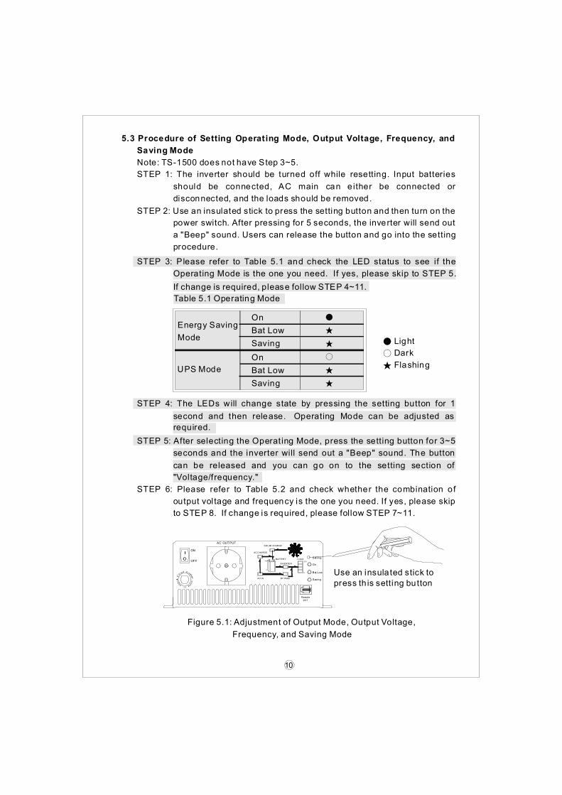
Table 5.1 Operating Mode
Figure 5.1: Adjustment of Output Mode, Output Voltage,
Frequency, and Saving Mode
Use an insulated stick to
press th is setting button
ON
AC OUTPUTSOLAR CHARGE
AC CHARGE
OFFBATTERY
100
0
10 0
0
Saving
Bat Low
On
Settin gLOAD
INVERTER
BY PASSAC IN
Remoteport
10
5.3 Procedure of Setting Operating Mode, Output Voltage, Frequency, and
Saving Mode
Note: TS-1500 does not have Step 3~5.
STEP 1: The inverter should be turned off while resetting. Input batteries
STEP 2: Use an insulated stick to press the setting button and then turn on the
STEP 3: Please refer to Table 5.1 and check the LED status to see if the
STEP 4: The LEDs will change state by pressing the setting button for 1
STEP 5: After selecting the Operat ing Mode, press the setting button for 3~5
STEP 6: Please refer to Table 5.2 and check whether the combination of
should be connected, AC main can either be connected or
power switch. After pressing for 5 seconds, the inverter will send out
Operating Mode is the one you need. If yes, please skip to STEP 5.
second and then release. Operating Mode can be adjusted as
seconds and the inverter will send out a "Beep" sound. The button
output vol tage and frequency is the one you need. If yes, please skip
to STEP 8. If change is required, please follow STEP 7~11.
can be released and you can go on to the setting section of
"Voltage/frequency."
required.
If change is required, please follow STEP 4~11.
a "Beep" sound. Users can release the button and go into the setting
procedure.
disconnected, and the loads should be removed.
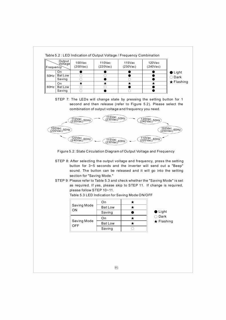
Bat Low
Bat Low
Saving
Saving
On
On
Table 5.3 LED Indication for Saving Mode ON/OFF
● Light
○ Dark
★ Flashing
●
★
★
★
★
○
Figure 5.2: State Circu lation Diagram of Output Voltage and Frequency
Table 5.2 : LED Indication of Output Voltage / Frequency Combination
50Hz
60Hz
100Vac 110Vac 115Vac 120Vac
(200Vac)
●On
On
●
●
●
●
●
●● Light
●○ Dark
●●●●
○Bat Low
Bat Low
○
○Saving
Saving
○
★ ★ Flashing★★★
○ ○
○ ○
(220Vac) (230Vac) (240Vac)
OutputVoltage
Frequency
100Vac(200Vac)50Hz
110Vac(220Vac)50Hz
115Vac(230Vac)50Hz
100Vac(200Vac)60Hz
120Vac(240Vac)50Hz
120Vac(240Vac)60Hz 110Vac
(220Vac)60Hz115Vac(230Vac)60Hz
Sav ing Mode
ON
Saving Mode
OFF
11
STEP 7: The LEDs will change state by pressing the setting button for 1
second and then release (refer to Figure 5.2). Please select the
combination of output voltage and frequency you need.
STEP 8: After selecting the output vol tage and frequency, press the setting
STEP 9: Please refer to Table 5.3 and check whether the "Saving Mode" is set
button for 3~5 seconds and the inverter will send out a "Beep"
as required. I f yes, please skip to STEP 11. If change is required,
please fol low STEP 10~11.
sound. The button can be released and it wi ll go into the setting
section for "Saving Mode."

12
STEP 10: The LEDs will change state by pressing the setting button for 1
STEP 11: After activat ing or canceling the "Saving Mode", press the setting
second and then release. You can activate or cancel the "Saving
button for around 5 seconds and the inverter will send out a "Beep"
sound. The button can be released and al l the sett ings are finished.
The inverter will automatically store all the settings and then start
to operate.
Mode" function by this adjustment.
5.4 Remote Monitoring Software
6.1 Input Protection
(A)Battery Polarity Protection: If the battery input is connected in reverse
(B)Battery Under Voltage Protection: When the battery vol tage is lower than
(C)Battery Over Voltage Protection: When the battery voltage is too high,
(D)Solar Charger Over Current Protection: The maximum charging current
Please choose suitable batteries that is within the rated input DC
voltage of TN/TS-1500 (refer to the SPEC). If the input DC voltage is
too low (ex. using 12Vdc battery bank for 24Vdc input models), TN/TS-
1500 can't be started up properly. If the input DC voltage is too high
(ex. using 48Vdc battery bank for 24Vdc input models), TN/TS-1500
WARNING:
will be damaged!
polarity, the internal fuse will blow and the inverter should be send back to
the preset value, the inverter will automatically terminate the output and
inverter will automatical ly terminate the output and the built- in buzzer will
of the built-in solar charger is 30A. I f the charging current is too high, the
internal fuse will blow and the inverter should be send back to MEAN WELL
for repair.
activate to inform the users. Please refer to Table 6.1 for more detail about
the failure signals displayed through the "Load Meter."
"Battery Low" signal on the front panel will light up. Please refer to Table 6.1
for more detail about the failure signals d isplayed through the "Load Meter."
MEAN WELL for repair.
(A)Users can also make Operating Mode, voltage/frequency, saving mode,
(B)DB9-USB conversion cable should not be used because it wi ll not be
and transition voltage adjustments by using this software. Software update
compatible with the monitor ing software.
can be downloaded from the MW website. Please contact us or our
distributor if you have any questions.
6. Protection

13
100
0
0
LOAD
100 10 0
100
100
0 0
0
LOAD LOA D
LO AD
LOAD
Table 6.1: Failure Messages On Front Panel
10 0
100
100
100
0
0
0
0
LOAD
LOAD
LOAD
LOAD
(>1875W)
OutputOverload
OutputOverload
(1500W~1750W)
Failure
Message
OutputOverload
Over
Temperature
(1750W~1875W)
LED
Indicator
LED
Indicator
AC Output
Short Circuit
Failure
Message
AbnormalAC OutputVoltage
AbnormalBatteryVoltage
6.2 Output Protection
(A)Bypass Mode: Uses "No Fuse Breaker" as automatic over current
(B)Inverter Mode: Under the "Inverter Mode", if any abnormal situation
(1)Over Temperature Protection: When the internal temperature is h igher
(2)AC Output Abnormal Protection: When the AC output voltage of the
(3)AC Output Short Circuit Protection: When a short circuit situation
(4)Battery Voltage Abnormal Protection: When the battery voltage is too
(5)Output Overload Protection: When output is overloaded between 1500W
protect ion. When over current occurs, the button of the circuit breaker on
occurs, the front panel will send out fai lure messages through the "Load
than the limit value, the "Over Temperature Protect ion" will be activated.
inverter is too high or too low, the unit will turn off and should be restarted
occurs at the output side of the inverter or the load increase greatly in a
high or too low, this protection will be activated. The inverter will auto-
~ 1750W, the inverter can continuously provide power for 3 minutes. After
that, if the overload condition is not removed, the overload protection will
be activated. When the load is higher than 1875W, the overload protection
wil l act ivate instant ly. For these overload protections, once activated, you
should reset the unit.
recover once the battery voltage go back to a safe level and users do not
need to restart it.
short period of time, the unit will turn off and should be restarted again.
again.
The unit will automatically turn off and should be restarted again.
Meter" (Please refer to Table 6.1).
the front panel will pop up and the inverter wil l shut down. At this time,
users should remove the loads, restart the inverter and press down on the
button of the circuit breaker and the AC output can now be provided
normal ly.
14
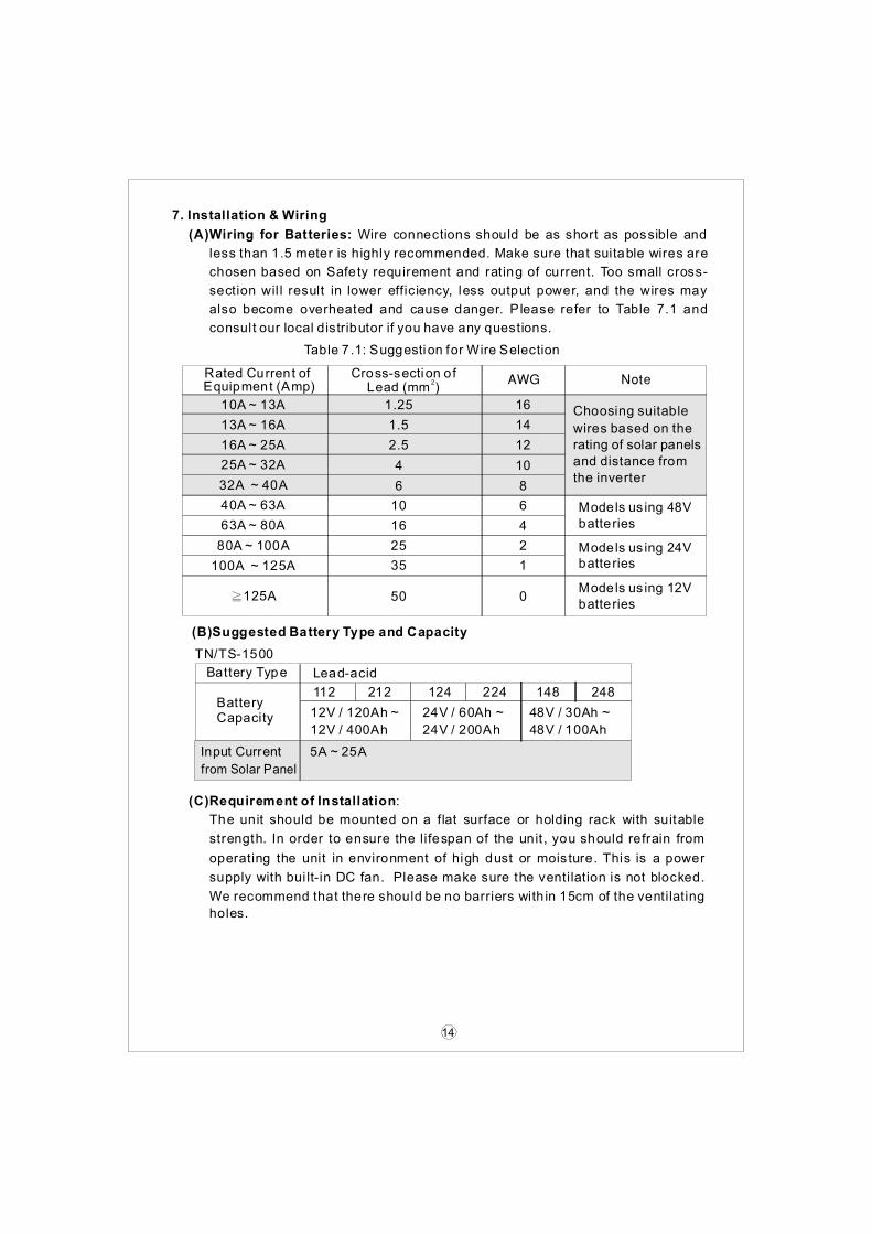
(B)Suggested Battery Type and Capacity
5A ~ 25A
Battery Type
BatteryCapacity
Lead-acid
12V / 120Ah ~ 24V / 60Ah ~ 48V / 30Ah ~
12V / 400Ah 24V / 200Ah 48V / 100Ah
112 212 124 224 148 248
TN/TS-1500
10A ~ 13A 1.25
1.5
2.5
4
6
10
16
25
35
50
16 Choosing suitable
wires based on therating of solar panels
and distance from
the inverter
14
12
10
8
6 Models us ing 48Vbatteries
Models us ing 24Vbatteries
Models us ing 12Vbatteries
4
2
1
0
13A ~ 16A
16A ~ 25A
25A ~ 32A
32A ~ 40A
40A ~ 63A
63A ~ 80A
80A ~ 100A
100A ~ 125A
≧125A
Cross-section ofLead (mm )
2Rated Current ofEquipment (Amp)
Table 7.1: Suggestion for Wire Selection
Input Current
from Solar Panel
(A)Wiring for Batteries: Wire connections should be as short as possible and
less than 1.5 meter is highly recommended. Make sure that suitable wires are
chosen based on Safety requirement and rating of current. Too small cross-
section wil l result in lower efficiency, less output power, and the wires may
also become overheated and cause danger. Please refer to Table 7.1 and
consult our local distributor if you have any questions.
7. Installation & Wiring
(C)Requirement of Installation:
The unit should be mounted on a flat surface or holding rack with suitable
strength. In order to ensure the lifespan of the unit , you should refrain from
operating the unit in environment of high dust or mois ture. This is a power
supply with bui lt-in DC fan. Please make sure the ventilation is not blocked.
We recommend that there should be no barriers with in 15cm of the ventilating
holes.

15
Solar Panel
LOAD
TN/TS-1500
Inverter
AC O/P
AC I/P DC I/P
- +
Chassis
Solar I/P
Wall or system FG
+ -
Battery
(D)Example of System Diagram
Figure 7.1: Example of Installation
>15cm
Inverter Air
>15cm
Air
As short as possible
Larger
Larger
than
than
15cm
15cm
Should less than 1.5m
Based on the actual length of wiring and
choose suitable cross-section of the leads
Where, the DC I/P and chassis f ix manner as following :

16
Chassis
0 10 20 30 40 50 60 70
20
40
60
80
100
21VDC 23VDC 30VDC (HORIZONTAL)
20
40
60
80
100
(E)Derating
Battery Input Voltage (V) - 24V ModelAmbient Temperature ( )℃
Figure 7.2: Output Derating Curve Figure 7.3: Input Derating Curve
1. Company Name : Mean Well Enterprises Co Ltd
2. Model Name : 1GG1HS-191
3. Rating : 150A
4. Torque : 106.2 Ib.in max.
5. Suitable Wire : Copper wire (temp rating : 75C )
6. Intended for termination onto a Listed ring tongue connector
7. To Be Sold Only With Installation Instructions
8. Amounting screw that is first inserted through the tang and is threaded
into the connector to secure the connector to the tang shall be torqued
to 32 in-lbs minimum
9. Mounting Screws - Plated Steel . Two provided, size M4
Cat.No.(1GG1HS-212)
Wire Range (10-4AWG
Str Cu Soldered Wires)
Torque (17.7-26.5 in lb)
(F) Notes on Output Loads:
TN/TS-1500 Series can power most of equipments that need an AC
source of 1500W. But for certain specific type of load, the unit may not
work properly.
(1)Since inductive loads or motor based equipments need a large start up
(2)When the output are capacit ive or rectified equipments (such as switching
current (6~10 times of i ts rated current), please make sure this start up
power supply), we suggest operating these equipment at no load or light
load condition. Increase the loads slight ly only after the TN/TS-1500 has
started up to ensure proper operation.
current is less than the maximum current capability of the inverter.

Malfunct ion of the charger
(no charging voltage)
Repair required. Please send it back
to us or any of our distributors
Clog with foreign objects Remove the foreign objectsFan doesnot sp in Malfunct ion of the fan
Repair required. Please send it backto us or any of our distributors
Short circuit protectionMake sure the output is not
overloaded or short circui t
Batteries are aging or broken Replace the batteriesDischargingperiod ofbatter ies istoo short
Battery capacity is too smallReconfirm the specification and enlarge
the battery capac ity as suggested
Status Possible Reasons Ways to Eliminate
Abnormal input
Check the AC or DC input sources.
Make sure the voltage is within the
required range.
No input (battery, AC main,or solar energy)
Make sure the wiring and polarityis correct.
Over temperatureprotection
Make sure that the ventila tion is not
b locked or whether the ambienttemperature is too high. Pleasederate output usage or reduce the
ambient temperature.
Overload protect ion
Make sure the output load does not
exceed the rated value or theinstantaneous start up current is not
too high (for inductive or capacitiveloads).
No AC outputvoltage
17
TN/TS-1500 should serviced by a professional technician. Improper usage or
modification may damage the unit or result in shock hazard. If you are not able to
clear the failure condition, please contact Mean WELL or any of our dis tributors
for repair service.
8. Failure Correction Notes
Three years of global warranty is provided for TN/TS-1500 under normal
operating conditions. Please do not change components or modify the unit
by yourself or MEAN WELL may reserve the right not to provide the complete
warranty.
9.Warranty

No.28 , Wuquan 3rd Rd., Wugu Dis t . , New Ta i pe i C i t y 248 , Ta iwan
Owner’s Manual
Quiet Mobile PowerCongratulations! You’ve purchased the most advanced, feature-rich Inverter/Charger designed for recreational vehicle applications. Tripp Lite
RV Inverter/Chargers are the quiet alternative to gas generators—with no fumes, fuel or noise to deal with! You get AC electricity anywhere
and anytime you need it: rolling down the highway, dry camping in majestic back country or parked overnight at a money-saving non-electric
site. RV Inverter/Chargers provide your equipment with utility- or generator-supplied AC electricity (filtered through premium ISOBAR® surge pro-
tection) whenever available. In addition, your RV Inverter/Charger automatically powers your RV’s 12V system and recharges your connected battery
bank—doing what traditional RV converter/chargers do. Whenever power blackouts, brownouts or high voltages occur, your RV Inverter/Charger imme-
diately and automatically switches over to inverting battery output to power connected AC equipment.
Better for Your Equipment Premium Protection Levels
• Built-In ISOBAR® Surge Protection
• Automatic Overload Protection
Ideal Output for All Loads (including computers)
• Frequency-Controlled Output
• Fast Load Switching
• Balanced Load Sharing*
Better for Your Batteries Faster Battery Recharge
• High-Amp, 3-Stage Battery Charger (adjustable)
Critical Battery Protection
• Battery Charge Conserver (Load Sense)*
• Battery Temperature Sensing*
• High-Efficiency DC-to-AC Inversion
Better for You Quiet, Simple, Maintenance-Free Operation
• Multi-Function Lights & Switches
• Automatic Generator Starting*
• Moisture-Resistant Construction†
Specifications/Warranty 2
Safety 3
Feature Identification 4
Operation 5
Configuration 6-7
Battery Selection 8
Mounting 9
Battery Connection 10
AC Input/Output Connection 11
Service/Maintenance/Troubleshooting 12 (back page)
PowerVerter®
RV Series (v. 3.0)
DC-to-AC Inverter/ChargersInput Output
Invert: 12 VDC 120V, 60 Hz. ACCharge: 120V, 60 Hz. AC 12 VDC
1111 W. 35th Street, Chicago, IL 60609 USACustomer Support: (773) 869-1234
www.tripplite.com
* Available on all models except 612 models. †Inverter/Chargers are moisture-resistant, not waterproof.
Copyright © 2003. PowerVerter® is a registered trademark of Tripp Lite. All rights reserved.
Contents

Inve
rter
/Ch
arg
er D
C V
olt
:12
Wir
e G
aug
e
Twin
00
(2/0
)W
atts
64
20
00 (2
/0)
(RV2
012O
EM, R
V251
2OEM
& R
V301
2OEM
only
)
500
15 ft
25 ft
39 ft
62 ft
79 ft
158
ft.70
011
ft18
ft28
ft44
ft56
ft11
2 ft.
1000
N/R
12 ft
20 ft
31 ft
39 ft
78 ft
.20
00N
/RN
/RN
/R16
ft20
ft40
ft.
2400
N/R
N/R
N/R
13 ft
16 ft
32 ft
.30
00N
/RN
/RN
/R10
ft13
ft26
ft.
† N
/R =
Not
Rec
omm
ende
d. N
OTE
: Acc
epta
ble
pow
er is
dire
ctly
rela
ted
to c
able
leng
th (i
.e. -
the
shor
ter t
he c
able
, the
bet
ter t
he p
erfo
rman
ce)
2R
Sp
ecif
icat
ion
s
Lim
ited
War
ran
tyTr
ipp
Lite
war
rant
s its
Inve
rter
/Cha
rger
s to
be
free
from
def
ects
in m
ater
ials
and
wor
kman
ship
for
a 30
mon
th p
erio
d fro
m th
e da
te o
f ret
ail p
urch
ase
by e
nd u
ser.
Trip
p Li
te’s
obl
igat
ion
unde
r th
is w
arra
nty
is li
mite
d to
rep
airin
g or
rep
laci
ng (
at it
s so
le o
ptio
n) a
ny s
uch
defe
ctiv
e pr
oduc
ts.T
o ob
tain
ser
vice
und
er th
is w
arra
nty
you
mus
t obt
ain
a R
etur
ned
Mat
eria
l Aut
horiz
atio
n (R
MA
) num
ber f
rom
Trip
p Li
te o
r an
auth
oriz
ed T
ripp
Lite
ser
vice
cen
ter.
Pro
duct
s m
ust b
e re
turn
ed to
Trip
p Li
teor
an
auth
or-
ized
Trip
p Li
te s
ervi
ce c
ente
r w
ith tr
ansp
orta
tion
char
ges
prep
aid
and
mus
t be
acco
mpa
nied
by
a br
ief d
escr
iptio
n of
the
prob
lem
enc
ount
ered
and
proo
f of d
ate
and
plac
e of
pur
chas
e.T
his
war
rant
y do
es n
ot a
pply
to e
quip
men
t whi
ch h
as b
een
dam
aged
by
acci
dent
, neg
ligen
ce o
r m
isap
plic
atio
n or
has
bee
nal
tere
d or
mod
ified
in a
ny w
ay,
incl
udin
g op
enin
g of
the
uni
t’s c
asin
g fo
r an
y re
ason
.Thi
s w
arra
nty
appl
ies
only
to
the
orig
inal
pur
chas
er w
ho m
ust
have
pro
perly
reg
iste
red
the
prod
uct
with
in 1
0 da
ys o
f re
tail
purc
hase
.
EX
CE
PT
AS
PR
OV
IDE
D H
ER
EIN
, TR
IPP
LIT
E M
AK
ES
NO
WA
RR
AN
TIE
S, E
XP
RE
SS
OR
IMP
LIE
D, I
NC
LUD
ING
WA
RR
AN
TIE
S O
F M
ER
CH
AN
TAB
ILIT
Y A
ND
FIT
NE
SS
FO
R A
PA
RT
ICU
LAR
PU
RP
OS
E.S
ome
stat
es d
o no
t per
mit
limita
tion
or e
xclu
sion
of i
mpl
ied
war
rant
ies;
ther
efor
e, th
e af
ores
aid
limita
tion(
s) o
r exc
lusi
on(s
)m
ay n
ot a
pply
to
the
purc
hase
r.
EX
CE
PT
AS
PR
OV
IDE
D A
BO
VE
, IN
NO
EV
EN
T W
ILL
TR
IPP
LIT
E B
E L
IAB
LE F
OR
DIR
EC
T, IN
DIR
EC
T, S
PE
CIA
L, IN
CID
EN
TAL
OR
CO
NS
EQ
UE
NT
IAL
DA
MA
GE
S A
RIS
ING
OU
T O
F T
HE
US
E O
F T
HIS
PR
OD
UC
T, E
VE
N IF
AD
VIS
ED
OF
TH
E P
OS
SIB
ILIT
Y O
F S
UC
H D
AM
AG
E.S
peci
fical
ly, T
ripp
Lite
is n
ot li
able
for
any
cost
s, s
uch
as lo
st p
rofit
s or
rev
enue
, lo
ss o
f eq
uipm
ent,
loss
of
use
of e
quip
men
t, lo
ss o
f so
ftwar
e, lo
ss o
f da
ta,
cost
s of
sub
stitu
tes,
cla
ims
by t
hird
par
ties,
or
othe
rwis
e.
Trip
p Li
te h
as a
pol
icy
of c
ontin
uous
impr
ovem
ent.
Spe
cific
atio
ns a
re s
ubje
ct t
o ch
ange
with
out
notic
e.
No
te o
n L
abel
ing
Tw
o s
ymb
ols
are
use
d o
n t
he
RV
lab
els.
V~
:A
C V
olt
age
:
DC
Vo
ltag
e
Min
imu
m R
ecom
men
ded
Cab
le S
izin
g C
hart†
Use
in c
onju
nct
ion w
ith D
C w
irin
g c
onnec
tion i
nst
ruct
ions
in t
he
Bat
tery
Connec
tion s
ecti
on.
MO
DE
L N
UM
BE
R:
RV
612U
LR
V61
2UL
HR
V10
12U
LR
V10
12U
LH
RV
1512
RV
1512
OE
MR
V20
12O
EM
RV
2012
UL
RV
2512
OE
MR
V30
12O
EM
Ser
ies
Num
ber:
AG
AP
6001
2MV
JA
GA
P60
012M
VJ
AG
AP
1000
12M
V3
AG
AP
1000
12M
V3
AG
AP
2000
12M
V3
AG
AP
2000
12M
VP
3A
GA
P20
0012
MV
P3
AG
AP
2000
12M
V3
AC
Inpu
t C
onne
ctio
n:In
put
Cor
dH
ardw
ireIn
put
Cor
dH
ardw
ireH
ardw
ireH
ardw
ireH
ardw
ireH
ardw
ireH
ardw
ireH
ardw
ire
INV
ER
TE
R
Com
mon
Spe
cific
atio
ns fo
r A
ll M
odel
s:•
DC
Inpu
t Vol
ts (
Nom
inal
):12
VD
C •
· D
C In
put V
olta
ge R
ange
:10
- 15
VD
C •
Out
put V
olts
(N
omin
al):
120
VAC
, ± 5
% •
Out
put F
requ
ency
(N
omin
al):
60 H
z, ±
0.5
% •
Effi
cien
cy:8
8% to
94%
, dep
endi
ng o
n lo
ad a
nd te
mpe
ratu
re
Sel
ect T
rip
p L
ite
Inve
rter
/Ch
arg
ers
incl
ud
e a
Bat
tery
Ch
arg
e C
on
serv
er (
Lo
ad S
ense
) C
on
tro
l wh
ich
sav
es b
atte
ry p
ow
er b
y al
low
ing
use
rs t
o s
et t
he
min
imu
m lo
ad le
vel a
t w
hic
h t
he
un
it’s
inve
rter
tu
rns
on
.Use
rs c
an s
ign
ific
antly
red
uce
th
e N
o L
oad
DC
Inp
ut
Cu
rren
t (a
pp
roxi
mat
ely
2.5
to 4
A f
or
all m
od
els)
to
a v
ery
low
am
p le
vel w
ith
th
e u
se o
f th
is c
on
tro
l.C
ontin
uous
Pow
er (
@ 2
0 C
):60
060
010
0010
0015
0015
0020
0020
0025
0030
00O
verP
ower
™ P
eak
Sur
ge P
ower
:*90
090
015
0015
0022
5022
5030
0030
0037
5045
00D
oubl
e B
oost
™ P
eak
Sur
ge P
ower
:*12
0012
0020
0020
0030
0030
0040
0040
0050
0060
00M
axim
um O
utpu
t A
C C
urre
nt
5 A
5 A
8.3
A8.
3 A
12.5
A12
.5 A
16.7
A16
.7 A
20 A
25 A
(Con
tinuo
us):
UL
Req
uire
d D
C F
use
TP
N-8
0 (fu
se)
TP
N-8
0 (fu
se)
AN
L-20
0 (fu
se)
AN
L-20
0 (fu
se)
AN
L-27
5tw
o A
NL-
200
(fuse
s)tw
o A
NL-
200
(fuse
s)A
NL-
325
(fuse
)tw
o A
NL-
200
(fuse
s)tw
o A
NL-
275
(fuse
s)an
d F
use
Blo
ck:
R25
100-
1CR
(fu
se b
lock
)R
2510
0-1C
R (
fuse
blo
ck)
1DK
98 (
fuse
blo
ck)
1DK
98(f
use
bloc
k)1D
K98
(fus
e bl
ock)
two
1DK
98 (
fuse
blo
cks)
two
1DK
98 (
fuse
blo
cks)
1DK
98(f
use
bloc
k)tw
o 1D
K98
(fu
se b
lock
s)tw
o 1D
K98
(fu
se b
lock
s)B
ussm
ann
Bus
sman
nB
ussm
ann
Bus
man
nB
ussm
ann
Bus
sman
nB
ussm
ann
Bus
sman
n B
ussm
ann
Bus
sman
n (m
anuf
actu
rer)
(man
ufac
ture
r)(m
anuf
actu
rer)
(man
ufac
ture
r)(m
anuf
actu
rer)
(man
ufac
ture
r)(m
anuf
actu
rer)
(man
ufac
ture
r)(m
anuf
actu
rer)
(man
ufac
ture
r)D
C In
put C
urre
nt @
N
omin
al V
DC
Ful
l Loa
d:56
A56
A95
A95
A14
3 A
143
A19
2A19
0A24
0 A
290A
BA
TT
ER
Y C
HA
RG
ER
Com
mon
Spe
cific
atio
ns fo
r A
ll M
odel
s •
Acc
epta
nce
Volts
VD
C:S
elec
tabl
e 14
.4 V
** /
14.2
V W
et**
/ G
el •
Flo
at V
olts
DC
(w
/gel
):13
.3 V
(13
.6 V
) •
· Inp
ut V
olts
(N
omin
al):
120
VAC
Cha
rgin
g C
apac
ity D
C:
45 A
/ 1
1 A
**45
A /
11
A**
55 A
/ 1
4 A
**55
A /
14
A**
80 A
/ 2
0 A
**80
A /
20
A**
100
A /
25
A**
100
A /
25
A**
120
A /
30
A**
140
A /
35
A**
Inpu
t C
urre
nt A
C:
9.5
A9.
5 A
11.5
A11
.5 A
16.7
A16
.7 A
20 A
20 A
24 A
30 A
LIN
E V
AC
OP
ER
AT
ION
Com
mon
Spe
cific
atio
ns fo
r A
ll M
odel
s •
Inpu
t Fre
quen
cy (
Nom
inal
):60
Hz,
±10
%•
Max
imum
Inpu
t Vol
ts (
Tran
sfer
to B
atte
ry)
(Con
tinuo
us, C
harg
er a
t Max
imum
):S
elec
tabl
e 13
5**
or 1
45 V
AC
Min
imum
Inp
ut V
olts
:S
elec
tabl
e 95
** o
r S
elec
tabl
e 95
** o
rS
elec
tabl
e 75
**,
85,
Sel
ecta
ble
75**
, 85
, S
elec
tabl
e 75
**,
85,
Sel
ecta
ble
75**
, 85
, S
elec
tabl
e 75
**,
85,
Sel
ecta
ble
75**
, 85
, S
elec
tabl
e 75
**,
85,
Sel
ecta
ble
75**
, 85
, (T
rans
fer
to B
atte
ry)
105
VA
C10
5 V
AC
95 o
r 10
5 V
AC
95 o
r 10
5 V
AC
95 o
r 10
5 V
AC
95 o
r 10
5 V
AC
95 o
r 10
5 V
AC
95 o
r 10
5 V
AC
95 o
r 10
5 V
AC
95 o
r 10
5 V
AC
Max
imum
Inp
ut A
C C
urre
nt
11.3
A14
.5 A
12.1
A20
A29
A29
A38
A38
A44
A56
A(C
ontin
uous
, Cha
rger
at
Max
imum
):M
axim
um B
ypas
s A
CC
urre
nt:
6 A
6A12
A12
A20
A15
/20
A15
/20
A20
A20
/20
A20
/20
A(L
oad
circ
uit b
reak
er li
mite
d)* O
verP
ower
dur
atio
n (u
p to
1 h
our).
Dou
bleB
oost
dur
atio
n (u
p to
10
seco
nds)
. Act
ual d
urat
ion
depe
nds
on b
atte
ry a
ge, b
atte
ry c
harg
e le
vel a
nd a
mbi
ent t
empe
ratu
re. *
*Fac
tory
set
ting.
The
pol
icy
of T
ripp
Lite
is o
ne o
f con
tinuo
us im
prov
emen
t. Sp
ecifi
catio
ns a
re s
ubje
ct to
cha
nge
with
out n
otic
e.

3R
Important Safety Instructions
SAVE THESE INSTRUCTIONS!This manual contains important instructions and warnings that should be followed during the installation, operation and storage of all Tripp LiteInverter/Chargers.
Location Warnings• Install your Inverter/Charger (whether for a mobile or stationary application) in a location or compartment that minimizes exposure to
heat, dust, direct sunlight and moisture.
• Although your Inverter/Charger is moisture resistant, it is NOT waterproof. Flooding the unit with water will cause it to short circuit and could cause personal injury due to electric shock. Never immerse the unit, and avoid any area where standing water might accumulate. Mounting should be in the driest location available.
• Leave a minimum of 2" clearance at front and back of the Inverter/Charger for proper ventilation. To avoid automatic Inverter/Chargershutdown due to overtemperature, any compartment that contains the Inverter/Charger must be properly ventilated with adequate outside air flow. The heavier the load of connected equipment, the more heat will be generated by the unit.
• Do not install the Inverter/Charger directly near magnetic storage media, as this may result in data corruption.
• Do not install near flammable materials, fuel or chemicals.
Battery Connection Warnings• The Inverter/Charger will not operate (with or without utility power) until batteries are connected.
• Multiple battery systems must be comprised of batteries of identical voltage, age, amp-hour capacity and type.
• Because explosive hydrogen gas can accumulate near batteries if they are not kept well ventilated, your batteries should not be installed (whether for a mobile or stationary application) in a “dead air” compartment. Ideally, any compartment would have some ventilation to outside air.
• Sparks may result during final battery connection. Always observe proper polarity as batteries are connected.
• Do not allow objects to contact the two DC input terminals. Do not short or bridge these terminals together. Serious personal injury or property damage could result.
Equipment Connection WarningsDo not use a Tripp Lite RV Inverter/Charger in life support or healthcare applications where a malfunction or failure of a Tripp Lite RV Inverter/Charger could cause failure of, or significantly alter the performance of, a life support device ormedical equipment.
• Corded models: Do not modify the Inverter/Charger’s plug or receptacle in a way that eliminates its ground connection. Do not use power adapters that will eliminate the plug’s ground connection.
• Connect your Inverter/Charger only to a properly grounded AC power outlet or hardwired source. Do not plug the unit into itself; this will damage the device and void your warranty.
• You may experience uneven performance results if you connect a surge suppressor, line conditioner or UPS system to the output of the Inverter/Charger.
Operation Warnings• Your Inverter/Charger does not require routine maintenance. Do not open the device for any reason. There are no user serviceable parts
inside.
• Potentially lethal voltages exist within the Inverter/Charger as long as the battery supply and/or AC input are connected. During any service work, the battery supply and AC input connection (if any) should therefore be disconnected.
• Do not connect or disconnect batteries while the Inverter/Charger is operating in either inverting or charging mode. Operating Mode Switch should be in the OFF position. Dangerous arcing may result.

4R
Feature Identification
Identify the premium features on your specific model and quickly locate instructions on how to maximize their use.
Configuration DIP Switches: optimize Inverter/Chargeroperation depending on your application. See pages 6-7 for setting instructions.
Operating Mode Switch: controls Inverter/Charger operation. The “AUTO/REMOTE” setting ensures your equipment receives constant, uninterrupted AC power. It also enables the Inverter/Charger to be remotely monitored and controlled with an optional remote module (Tripp Lite model APSRM2, soldseparately or included with select models). The “CHARGEONLY” setting allows your batteries to return to full charge fasterby turning the inverter off which halts battery discharging. Seepage 5 for setting instructions.
Operation Indicator Lights: intuitive “traffic light” signals show whether the Inverter/Charger is operating from AC line power or DC battery power. It also warns you if the connected equipment load is too high. See page 5 for instructions on reading indicator lights.
Battery Indicator Lights: intuitive “traffic light” signals show approximate charge level of your battery. See page 5 for instructions on reading indicator lights.
DC Power Terminals: connect to your battery terminals. See page 10 for connection instructions.
Ground Fault Interrupter (GFI) AC Receptacles (not on hardwire models): allow you to connect equipment that wouldnormally be plugged into a utility outlet. They feature ground fault interrupter switches that trip if there is excessive current on the ground safety wire.
AC Input Cord (not on hardwire models): connects the Inverter/Charger to any source of utility- or generator-supplied AC power. See page 11 for connection instructions.
Hardwire AC Input/Output Terminals (not on corded models): securely connect the Inverter/Charger to vehicle orfacility electrical system input and recommended GFCI receptacleoutput. See page 11 for connection instructions.
Resettable Circuit Breaker: protect your Inverter/Charger againstdamage due to overload. See page 5 for resetting instructions.
Remote Control Module Connector: allows remote monitoringand control with an optional module (Tripp Lite modelAPSRM2, sold separately or included with select models). Seeremote module owner’s manual for connection instructions.
Battery Charge Conserver (Load Sense) Dial (not on 612models): conserves battery power by setting the low-load levelat which the Inverter/Charger’s inverter automatically shuts off.See page 7 for setting instructions.
Main Ground Lug: properly grounds the Inverter/Charger tovehicle grounding system or to earth ground. See page 10 for connection instructions.
Multi-Speed Cooling Fan: quiet, efficient fan prolongs equipmentservice life.
DC Power Terminal Cover Plate
Hardwire AC Input/Output Cover Plate
Battery Temperature Sensing Connector (not on 612 models):prolongs battery life by adjusting charge based on battery tem-perature. Use with cable (included on select models). See page7 for details.
Automatic Generator Start Connector (not on 612 models):automatically cycles generator based on battery voltage. Usewith user-supplied cable. See page 7 for details.
1
2
3
4
5
6
7
8
9
10
11
12
13
14
15
HOT IN
NEUTRAL IN
GROUND IN
GROUND OUT
HOT OUT
“FOR USE WITH COPPER WIRE ONLY”
NEUTRAL OUT
1 24 3
5
9
10 111314
8 15Front View (Single Input/Output Hardwire Models)
12
Rear View (Single Input/Output Hardwire Models and Select Corded Models)
AC IN 1
HOT - BROWN NEU - BLUEGND - GRN/YEL
AC IN 2
HOT - GRAY NEU - WHITEGND - GRN/YEL
AC OUT 1
HOT - BLACK NEU - YELLOWGND - GRN/YEL
AC OUT 2
HOT - ORANGE NEU - REDGND - GRN/YEL
1 24 3
5
9
10 1113
Front View (Dual Input/Output Hardwire Models)
Front View (Corded Models) * 612 models have only one set of DIP Switches. ** Select models include front-mounted ground lug. † Available on all models except 612 models.
24 3
5
6
7
9
10 11†1314 1*
12**
8
16
17
16†
17†
Side Mounted,
Not Shown
Side Mounted,
Not Shown
16
17
Side Mounted,
Not Shown
Side Mounted,
Not Shown
16
17
12

5R
Operation
Switch ModesAfter configuring, mounting and connecting your Inverter/Charger,you are able to operate it by switching between the following oper-ating modes as appropriate to your situation:
AUTO/REMOTE: Switch to this mode when you needconstant, uninterrupted AC power for connectedappliances and equipment. The Inverter/Charger willcontinue to supply AC power to connected equipment andto charge your connected batteries while utility- orgenerator-supplied AC power is present. Since the inverter is ON (but inStandby) in this mode, it will automatically switch to your batterysystem to supply AC power to connected equipment in the absenceof a utility/generator source or in over/under voltage situations.“AUTO/REMOTE” also enables an optional remote control module(Tripp Lite model APSRM2, sold separately or included with selectmodels) to function when connected to the unit.
CHARGE ONLY: Switch to this mode when youare not using connected appliances and equipment inorder to conserve battery power by disabling theinverter. The Inverter/Charger will continue to supplyAC power to connected equipment and charge con-nected batteries while utility- or generator-supplied AC power ispresent. However, since the inverter is OFF in this mode, it WILL NOTsupply AC power to connected equipment in the absence of autility/generator source or in over/under voltage situations.
OFF: Switch to this mode to shut down theInverter/Charger completely, preventing the inverterfrom drawing power from the batteries, and prevent-ing utility AC from passing through to connectedequipment or charging the batteries. Use this switchto automatically reset the unit if it shuts down due to overload oroverheating. First remove the excessive load or allow the unit to suf-ficiently cool (applicable to your situation). Switch to “OFF”, thenback to “AUTO/REMOTE” or “CHARGE ONLY” as desired. Ifunit fails to reset, remove more load or allow unit to cool further andretry. Use an optional remote control module (Tripp Lite modelAPSRM2, sold separately or included with select models) to resetunit due to overload and overtemperature.
Indicator LightsYour Inverter/Charger (as well as an optional Tripp Lite RemoteControl Module, sold separately or included with select models) isequipped with a simple, intuitive, user-friendly set of indicator lights.These easily-remembered “traffic light” signals will allow you, shortlyafter first use, to tell at a glance the charge condition of your batteries,as well as ascertain operating details and fault conditions.
LINE Green Indicator: If the operating modeswitch is set to “AUTO/REMOTE”, this light willILLUMINATE CONTINUOUSLY when your con-nected equipment is receiving continuous AC powersupplied from a utility/generator source.
If the operating mode switch is set to “CHARGE ONLY”, this lightwill BLINK to alert you that the unit’s inverter is OFF and will NOTsupply AC power in the absence of a utility/generator source or inover/under voltage situations.
INV (Inverting) Yellow Indicator: This light willILLUMINATE CONTINUOUSLY whenever connectedequipment is receiving battery-supplied, inverted ACpower (in the absence of a utility/generator source or inover/under voltage situations). This light will be offwhen AC power is supplying the load. This light will BLINK to alert you ifthe load is less than the Battery Charge Conserver (Load Sense) setting.
LOAD Red Indicator: This red light will ILLUMI-NATE CONTINUOUSLY whenever the inverter isfunctioning and the power demanded by connectedappliances and equipment exceeds 100% of loadcapacity. The light will BLINK to alert you when theinverter shuts down due to a severe overload or overheating. If thishappens, turn the operating mode switch “OFF”; remove the over-load and let the unit cool. You may then turn the operating modeswitch to either “AUTO/REMOTE” or “CHARGE ONLY” after ithas adequately cooled. This light will be off when AC power is sup-plying the load.
BATTERY Indicator Lights: These three lights will illuminate inseveral sequences to show the approximate charge level of your con-nected battery bank and alert you to two fault conditions:
Approximate Battery Charge Level*
Battery Lights Battery CapacityIlluminated (Charging/Discharging)
Green 91%–Full
Green & Yellow 81%–90%
Yellow 61%–80%
Yellow & Red 41%–60%
Red 21%–40%
All three lights off 1%–20%
Flashing red 0% (Inverter shutdown)
* Charge levels listed are approximate. Actual conditions vary
depending on battery condition and load.
Fault Condition
Battery Lights Fault Illuminated Condition
All three lights Excessive discharge flash slowly* (Inverter shutdown)
All three lights Overcharge (Charger flash quickly** shutdown)
*Approximately ½ second on, ½ second off. See Troubleshooting section. ** Approximately ¼
second on, ¼ second off. May also indicate a battery charger fault exists. See Troubleshooting
section.
Resetting Your Inverter/Charger toRestore AC PowerYour Inverter/Charger may cease supplying AC power or DC charg-ing power in order to protect itself from overload or to protect yourelectrical system. To restore normal functioning:
Overload Reset: Switch operating mode switch to “OFF” andremove some of the connected electrical load (ie: turn off some ofthe AC devices drawing power which may have caused the overloadof the unit). Wait one minute, then switch operating mode switchback to either “AUTO/REMOTE” or “CHARGE ONLY.”
Output Circuit Breaker Reset: Alternatively, check output circuitbreaker(s) on the unit's front panel. If tripped, remove some of the elec-trical load, then wait one minute to allow components to cool beforeresetting the circuit breaker. See Troubleshooting for other possiblereasons AC output may be absent.
1
2
3
4
5
6
7
1
2
1 2 3
4 5 6
7
1 2
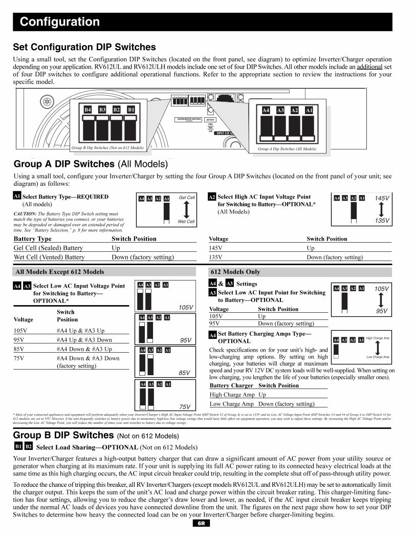
6R
Select Battery Type—REQUIRED
(All models)
CAUTION: The Battery Type DIP Switch setting must
match the type of batteries you connect, or your batteries
may be degraded or damaged over an extended period of
time. See “Battery Selection,” p. 8 for more information.
Battery Type Switch Position
Gel Cell (Sealed) Battery Up
Wet Cell (Vented) Battery Down (factory setting)
Select High AC Input Voltage Point
for Switching to Battery—OPTIONAL*
(All Models)
Voltage Switch Position
145V Up
135V Down (factory setting)
Configuration
Set Configuration DIP SwitchesUsing a small tool, set the Configuration DIP Switches (located on the front panel, see diagram) to optimize Inverter/Charger operationdepending on your application. RV612UL and RV612ULH models include one set of four DIP Switches. All other models include an additional setof four DIP switches to configure additional operational functions. Refer to the appropriate section to review the instructions for your specific model.
A1A2A3A4 A1A2A3A4
INPUT C/B 10A OUTPUT C/B 12A
B4 B3 B2 B1 A4 A3 A2 A1
Group B Dip Switches (Not on 612 Models) Group A Dip Switches (All Models)
Group A DIP Switches (All Models)Using a small tool, configure your Inverter/Charger by setting the four Group A DIP Switches (located on the front panel of your unit; seediagram) as follows:
Select Low AC Input Voltage Point
for Switching to Battery—
OPTIONAL*
Switch
Voltage Position
105V #A4 Up & #A3 Up
95V #A4 Up & #A3 Down
85V #A4 Down & #A3 Up
75V #A4 Down & #A3 Down
(factory setting)
A1A2A3A4
A1A2A3A4
A1A2A3A4
A1A2A3A4
A1 A2
A3A4
B2B1
A1A2A3A4A3A4
A3
* Most of your connected appliances and equipment will perform adequately when your Inverter/Charger’s High AC Input Voltage Point (DIP Switch #2 of Group A) is set to 135V and its Low AC Voltage Input Point (DIP Switches #3 and #4 of Group A or DIP Switch #3 for
612 models) are set to 95V. However, if the unit frequently switches to battery power due to momentary high/low line voltage swings that would have little effect on equipment operation, you may wish to adjust these settings. By increasing the High AC Voltage Point and/or
decreasing the Low AC Voltage Point, you will reduce the number of times your unit switches to battery due to voltage swings.
Group B DIP Switches (Not on 612 Models)
Select Load Sharing—OPTIONAL (Not on 612 Models)
Your Inverter/Charger features a high-output battery charger that can draw a significant amount of AC power from your utility source orgenerator when charging at its maximum rate. If your unit is supplying its full AC power rating to its connected heavy electrical loads at thesame time as this high charging occurs, the AC input circuit breaker could trip, resulting in the complete shut off of pass-through utility power.
To reduce the chance of tripping this breaker, all RV Inverter/Chargers (except models RV612UL and RV612ULH) may be set to automatically limitthe charger output. This keeps the sum of the unit’s AC load and charge power within the circuit breaker rating. This charger-limiting func-tion has four settings, allowing you to reduce the charger’s draw lower and lower, as needed, if the AC input circuit breaker keeps trippingunder the normal AC loads of devices you have connected downline from the unit. The figures on the next page show how to set your DIPSwitches to determine how heavy the connected load can be on your Inverter/Charger before charger-limiting begins.
Set Battery Charging Amps Type—
OPTIONAL
Check specifications on for your unit’s high- andlow-charging amp options. By setting on highcharging, your batteries will charge at maximumspeed and your RV 12V DC system loads will be well-supplied. When setting onlow charging, you lengthen the life of your batteries (especially smaller ones).
A4
Select Low AC Input Point for Switching
to Battery—OPTIONAL
Voltage Switch Position
105V Up
95V Down (factory setting)
& Settings
612 Models OnlyAll Models Except 612 Models
Battery Charger Switch Position
High Charge Amp Up
Low Charge Amp Down (factory setting)
High Charge Amp
Low Charge Amp
A1A2A3A4
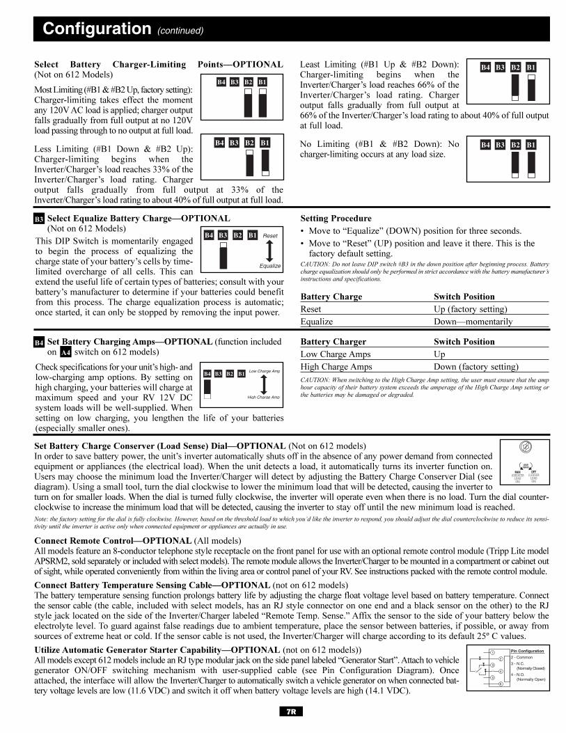
7R
Set Battery Charging Amps—OPTIONAL (function includedon switch on 612 models)
Check specifications for your unit’s high- andlow-charging amp options. By setting onhigh charging, your batteries will charge atmaximum speed and your RV 12V DCsystem loads will be well-supplied. Whensetting on low charging, you lengthen the life of your batteries(especially smaller ones).
Battery Charger Switch Position
Low Charge Amps Up
High Charge Amps Down (factory setting)
CAUTION: When switching to the High Charge Amp setting, the user must ensure that the amp
hour capacity of their battery system exceeds the amperage of the High Charge Amp setting or
the batteries may be damaged or degraded.
Select Equalize Battery Charge—OPTIONAL(Not on 612 Models)
This DIP Switch is momentarily engagedto begin the process of equalizing thecharge state of your battery’s cells by time-limited overcharge of all cells. This canextend the useful life of certain types of batteries; consult with yourbattery’s manufacturer to determine if your batteries could benefitfrom this process. The charge equalization process is automatic;once started, it can only be stopped by removing the input power.
Setting Procedure
• Move to “Equalize” (DOWN) position for three seconds.
• Move to “Reset” (UP) position and leave it there. This is the factory default setting.
CAUTION: Do not leave DIP switch #B3 in the down position after beginning process. Battery
charge equalization should only be performed in strict accordance with the battery manufacturer’s
instructions and specifications.
Battery Charge Switch Position
Reset Up (factory setting)
Equalize Down—momentarily
Select Battery Charger-Limiting Points—OPTIONAL(Not on 612 Models)
Most Limiting (#B1 & #B2 Up, factory setting):Charger-limiting takes effect the momentany 120V AC load is applied; charger outputfalls gradually from full output at no 120Vload passing through to no output at full load.
Less Limiting (#B1 Down & #B2 Up):Charger-limiting begins when theInverter/Charger’s load reaches 33% of theInverter/Charger’s load rating. Chargeroutput falls gradually from full output at 33% of theInverter/Charger’s load rating to about 40% of full output at full load.
Least Limiting (#B1 Up & #B2 Down):Charger-limiting begins when theInverter/Charger’s load reaches 66% of theInverter/Charger’s load rating. Chargeroutput falls gradually from full output at66% of the Inverter/Charger’s load rating to about 40% of full outputat full load.
No Limiting (#B1 & #B2 Down): Nocharger-limiting occurs at any load size.
Configuration (continued)
B1B2B3B4
B1B2B3B4
B1B2B3B4
B1B2B3B4
B1B2B3B4
Set Battery Charge Conserver (Load Sense) Dial—OPTIONAL (Not on 612 models)In order to save battery power, the unit’s inverter automatically shuts off in the absence of any power demand from connectedequipment or appliances (the electrical load). When the unit detects a load, it automatically turns its inverter function on.Users may choose the minimum load the Inverter/Charger will detect by adjusting the Battery Charge Conserver Dial (seediagram). Using a small tool, turn the dial clockwise to lower the minimum load that will be detected, causing the inverter toturn on for smaller loads. When the dial is turned fully clockwise, the inverter will operate even when there is no load. Turn the dial counter-clockwise to increase the minimum load that will be detected, causing the inverter to stay off until the new minimum load is reached.
Note: the factory setting for the dial is fully clockwise. However, based on the threshold load to which you’d like the inverter to respond, you should adjust the dial counterclockwise to reduce its sensi-
tivity until the inverter is active only when connected equipment or appliances are actually in use.
Connect Remote Control—OPTIONAL (All models)All models feature an 8-conductor telephone style receptacle on the front panel for use with an optional remote control module (Tripp Lite modelAPSRM2, sold separately or included with select models). The remote module allows the Inverter/Charger to be mounted in a compartment or cabinet outof sight, while operated conveniently from within the living area or control panel of your RV. See instructions packed with the remote control module.
Connect Battery Temperature Sensing Cable—OPTIONAL (not on 612 models)The battery temperature sensing function prolongs battery life by adjusting the charge float voltage level based on battery temperature. Connectthe sensor cable (the cable, included with select models, has an RJ style connector on one end and a black sensor on the other) to the RJstyle jack located on the side of the Inverter/Charger labeled “Remote Temp. Sense.” Affix the sensor to the side of your battery below theelectrolyte level. To guard against false readings due to ambient temperature, place the sensor between batteries, if possible, or away fromsources of extreme heat or cold. If the sensor cable is not used, the Inverter/Charger will charge according to its default 25º C values.
Utilize Automatic Generator Starter Capability—OPTIONAL (not on 612 models))All models except 612 models include an RJ type modular jack on the side panel labeled “Generator Start”. Attach to vehiclegenerator ON/OFF switching mechanism with user-supplied cable (see Pin Configuration Diagram). Onceattached, the interface will allow the Inverter/Charger to automatically switch a vehicle generator on when connected bat-tery voltage levels are low (11.6 VDC) and switch it off when battery voltage levels are high (14.1 VDC).
Reset
Equalize
B1B2B3B4
B4
B3
A4
1
2
3
4
5
6
Pin Configuration
2 - Common
3 - N.C. (Normally Closed)
4 - N.O. (Normally Open)
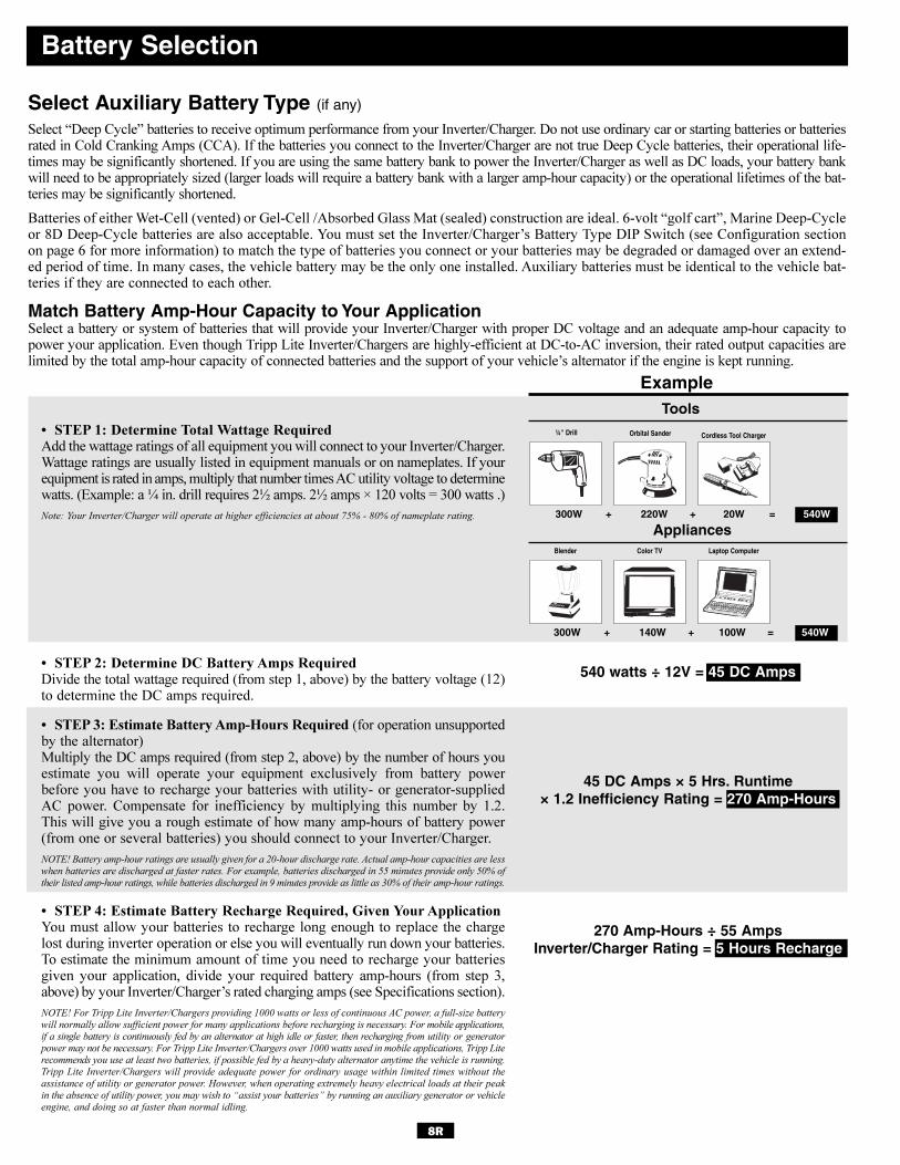
8R
Battery Selection
540 watts ÷ 12V = 45 DC Amps
270 Amp-Hours ÷ 55 Amps Inverter/Charger Rating = 5 Hours Recharge
Select Auxiliary Battery Type (if any)
Select “Deep Cycle” batteries to receive optimum performance from your Inverter/Charger. Do not use ordinary car or starting batteries or batteriesrated in Cold Cranking Amps (CCA). If the batteries you connect to the Inverter/Charger are not true Deep Cycle batteries, their operational life-times may be significantly shortened. If you are using the same battery bank to power the Inverter/Charger as well as DC loads, your battery bankwill need to be appropriately sized (larger loads will require a battery bank with a larger amp-hour capacity) or the operational lifetimes of the bat-teries may be significantly shortened.
Batteries of either Wet-Cell (vented) or Gel-Cell /Absorbed Glass Mat (sealed) construction are ideal. 6-volt “golf cart”, Marine Deep-Cycleor 8D Deep-Cycle batteries are also acceptable. You must set the Inverter/Charger’s Battery Type DIP Switch (see Configuration sectionon page 6 for more information) to match the type of batteries you connect or your batteries may be degraded or damaged over an extend-ed period of time. In many cases, the vehicle battery may be the only one installed. Auxiliary batteries must be identical to the vehicle bat-teries if they are connected to each other.
Match Battery Amp-Hour Capacity to Your ApplicationSelect a battery or system of batteries that will provide your Inverter/Charger with proper DC voltage and an adequate amp-hour capacity topower your application. Even though Tripp Lite Inverter/Chargers are highly-efficient at DC-to-AC inversion, their rated output capacities arelimited by the total amp-hour capacity of connected batteries and the support of your vehicle’s alternator if the engine is kept running.
• STEP 1: Determine Total Wattage RequiredAdd the wattage ratings of all equipment you will connect to your Inverter/Charger.Wattage ratings are usually listed in equipment manuals or on nameplates. If yourequipment is rated in amps, multiply that number times AC utility voltage to determinewatts. (Example: a ¼ in. drill requires 2½ amps. 2½ amps × 120 volts = 300 watts .)
Note: Your Inverter/Charger will operate at higher efficiencies at about 75% - 80% of nameplate rating.
• STEP 2: Determine DC Battery Amps RequiredDivide the total wattage required (from step 1, above) by the battery voltage (12)to determine the DC amps required.
• STEP 3: Estimate Battery Amp-Hours Required (for operation unsupportedby the alternator)Multiply the DC amps required (from step 2, above) by the number of hours youestimate you will operate your equipment exclusively from battery powerbefore you have to recharge your batteries with utility- or generator-suppliedAC power. Compensate for inefficiency by multiplying this number by 1.2.This will give you a rough estimate of how many amp-hours of battery power(from one or several batteries) you should connect to your Inverter/Charger.
NOTE! Battery amp-hour ratings are usually given for a 20-hour discharge rate. Actual amp-hour capacities are less
when batteries are discharged at faster rates. For example, batteries discharged in 55 minutes provide only 50% of
their listed amp-hour ratings, while batteries discharged in 9 minutes provide as little as 30% of their amp-hour ratings.
• STEP 4: Estimate Battery Recharge Required, Given Your ApplicationYou must allow your batteries to recharge long enough to replace the chargelost during inverter operation or else you will eventually run down your batteries.To estimate the minimum amount of time you need to recharge your batteriesgiven your application, divide your required battery amp-hours (from step 3,above) by your Inverter/Charger’s rated charging amps (see Specifications section).
NOTE! For Tripp Lite Inverter/Chargers providing 1000 watts or less of continuous AC power, a full-size battery
will normally allow sufficient power for many applications before recharging is necessary. For mobile applications,
if a single battery is continuously fed by an alternator at high idle or faster, then recharging from utility or generator
power may not be necessary. For Tripp Lite Inverter/Chargers over 1000 watts used in mobile applications, Tripp Lite
recommends you use at least two batteries, if possible fed by a heavy-duty alternator anytime the vehicle is running.
Tripp Lite Inverter/Chargers will provide adequate power for ordinary usage within limited times without the
assistance of utility or generator power. However, when operating extremely heavy electrical loads at their peak
in the absence of utility power, you may wish to “assist your batteries” by running an auxiliary generator or vehicle
engine, and doing so at faster than normal idling.
ExampleTools
300W + 220W + 20W = 540W
¼" Drill Orbital Sander Cordless Tool Charger
Appliances
300W + 140W + 100W = 540W
Blender Color TV Laptop Computer
45 DC Amps × 5 Hrs. Runtime× 1.2 Inefficiency Rating = 270 Amp-Hours
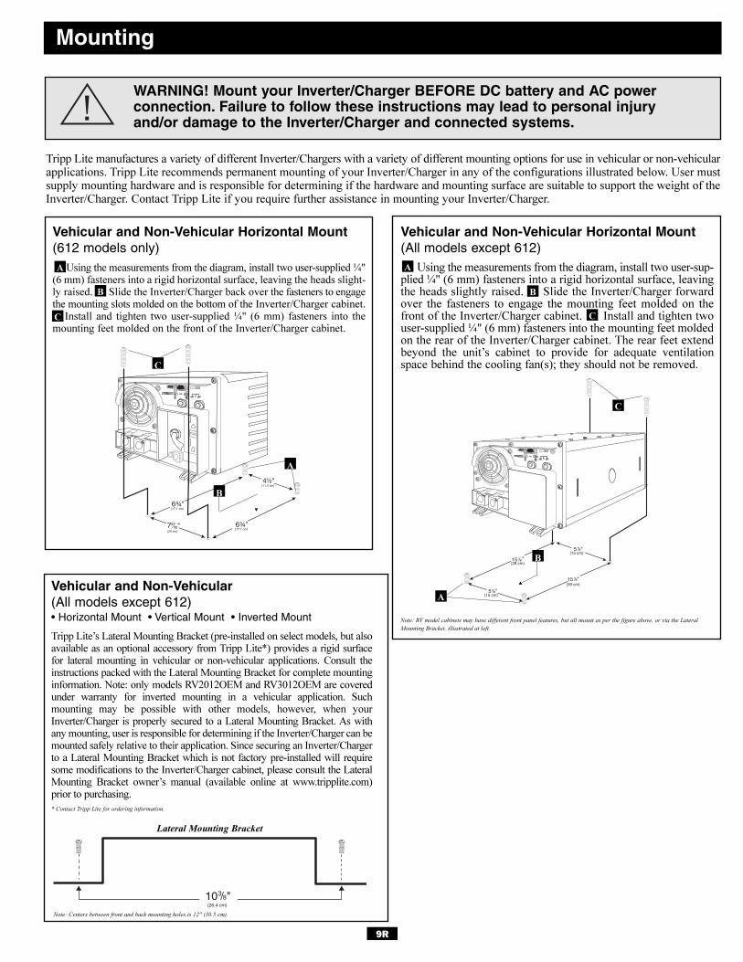
9R
Mounting
WARNING! Mount your Inverter/Charger BEFORE DC battery and AC power connection. Failure to follow these instructions may lead to personal injuryand/or damage to the Inverter/Charger and connected systems.
Tripp Lite manufactures a variety of different Inverter/Chargers with a variety of different mounting options for use in vehicular or non-vehicularapplications. Tripp Lite recommends permanent mounting of your Inverter/Charger in any of the configurations illustrated below. User mustsupply mounting hardware and is responsible for determining if the hardware and mounting surface are suitable to support the weight of theInverter/Charger. Contact Tripp Lite if you require further assistance in mounting your Inverter/Charger.
Vehicular and Non-Vehicular Horizontal Mount(612 models only)
Using the measurements from the diagram, install two user-supplied ¼"(6 mm) fasteners into a rigid horizontal surface, leaving the heads slight-ly raised. Slide the Inverter/Charger back over the fasteners to engagethe mounting slots molded on the bottom of the Inverter/Charger cabinet.
Install and tighten two user-supplied ¼" (6 mm) fasteners into themounting feet molded on the front of the Inverter/Charger cabinet.
Vehicular and Non-Vehicular Horizontal Mount(All models except 612)
Using the measurements from the diagram, install two user-sup-plied ¼" (6 mm) fasteners into a rigid horizontal surface, leavingthe heads slightly raised. Slide the Inverter/Charger forwardover the fasteners to engage the mounting feet molded on thefront of the Inverter/Charger cabinet. Install and tighten twouser-supplied ¼" (6 mm) fasteners into the mounting feet moldedon the rear of the Inverter/Charger cabinet. The rear feet extendbeyond the unit’s cabinet to provide for adequate ventilationspace behind the cooling fan(s); they should not be removed.
"
"
"
"
6¾"
4½"
72732" 6¾"
(11.4 cm)
(17.1 cm)(20 cm)
(17.1 cm)
C
B
�
A
C
B
�
A
B
A
B
C
"10(26.4 cm)
3
Note: RV model cabinets may have different front panel features, but all mount as per the figure above, or via the Lateral
Mounting Bracket, illustrated at left.
Vehicular and Non-Vehicular (All models except 612)• Horizontal Mount • Vertical Mount • Inverted Mount
Tripp Lite’s Lateral Mounting Bracket (pre-installed on select models, but alsoavailable as an optional accessory from Tripp Lite*) provides a rigid surface for lateral mounting in vehicular or non-vehicular applications. Consult theinstructions packed with the Lateral Mounting Bracket for complete mountinginformation. Note: only models RV2012OEM and RV3012OEM are coveredunder warranty for inverted mounting in a vehicular application. Such mounting may be possible with other models, however, when yourInverter/Charger is properly secured to a Lateral Mounting Bracket. As withany mounting, user is responsible for determining if the Inverter/Charger can bemounted safely relative to their application. Since securing an Inverter/Chargerto a Lateral Mounting Bracket which is not factory pre-installed will requiresome modifications to the Inverter/Charger cabinet, please consult the LateralMounting Bracket owner’s manual (available online at www.tripplite.com)prior to purchasing.
* Contact Tripp Lite for ordering information.
Lateral Mounting Bracket
Note: Centers between front and back mounting holes is 12" (30.5 cm).
A
C
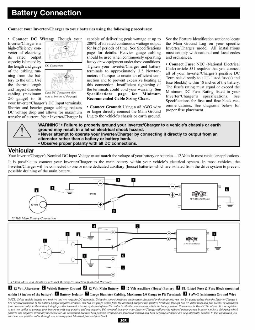
10R
• Connect DC Wiring: Though yourInverter/Charger is ahigh-efficiency con-verter of electricity,its rated outputcapacity is limited bythe length and gaugeof the cabling run-ning from the bat-tery to the unit. Usethe shortest lengthand largest diametercabling (maximum2/0 gauge) to fityour Inverter/Charger’s DC Input terminals.Shorter and heavier gauge cabling reducesDC voltage drop and allows for maximumtransfer of current. Your Inverter/Charger is
capable of delivering peak wattage at up to200% of its rated continuous wattage outputfor brief periods of time. See Specificationspage for details. Heavier gauge cablingshould be used when continuously operatingheavy draw equipment under these conditions.Tighten your Inverter/Charger and batteryterminals to approximately 3.5 Newton-meters of torque to create an efficient con-nection and to prevent excessive heating atthis connection. Insufficient tightening ofthe terminals could void your warranty. SeeSpecifications page for MinimumRecommended Cable Sizing Chart.
• Connect Ground: Using a #8 AWG wireor larger directly connect the Main GroundLug to the vehicle’s chassis or earth ground.
See the Feature Identification section to locatethe Main Ground Lug on your specificInverter/Charger model. All installationsmust comply with national and local codesand ordinances.
• Connect Fuse: NEC (National ElectricalCode) article 551 requires that you connectall of your Inverter/Charger’s positive DCTerminals directly to a UL-listed fuse(s) andfuse block(s) within 18 inches of the battery.The fuse’s rating must equal or exceed theMinimum DC Fuse Rating listed in yourInverter/Charger’s specifications. SeeSpecifications for fuse and fuse block rec-ommendations. See diagrams below forproper fuse placement.
Battery Connection
VehicularYour Inverter/Charger’s Nominal DC Input Voltage must match the voltage of your battery or batteries—12 Volts in most vehicular applications.
It is possible to connect your Inverter/Charger to the main battery within your vehicle’s electrical system. In most vehicles, theInverter/Charger will be connected to one or more dedicated auxiliary (house) batteries which are isolated from the drive system to preventpossible draining of the main battery.
12 Volt Inverter/Charger
12 Volts
12 Volts
3
5
12 Volt Main Battery Connection
12 Volt Alternator Vehicle Battery Ground 12 Volt Main Battery 12 Volt Auxiliary (House) Battery UL-Listed Fuse & Fuse Block (mounted
within 18 inches of the battery) Battery Isolator Large Diameter Cabling, Maximum 2/0 Gauge to Fit Terminals 8 AWG (minimum) Ground Wire
NOTE: Select models include two positive and two negative DC terminals. Using the same connection architecture illustrated in the diagrams, run two 2/0 gauge cables from the Inverter/Charger’s
two negative terminals to the battery’s single negative terminal; run two 2/0 gauge cables from the Inverter/Charger’s two positive terminals, through two UL-listed fuses and fuse blocks, or equivalent,
(one on each cable), to the battery’s single positive terminal. Use the equivalent of two 2/0 cables in all other connections within the battery system. Connection to Two DC Terminals: It is acceptable
to use two cables to connect your battery to only one positive and one negative DC terminal, however, your Inverter/Charger will provide reduced output power. It doesn’t make a difference which
positive and negative terminal you choose for the connection because both positive terminals are internally bonded and both negative terminals are also internally bonded. In this connection you
must run one positive cable through one user-supplied UL-listed fuse and fuse block.
876
54321
12 Volt Inverter/Charger
12 Volts
12 Volts
12 Volts
12 Volt Main and Auxiliary (House) Battery Connection (Isolated Parallel)
1
4
1
7
6
2
2
5
7
3
2
Connect your Inverter/Charger to your batteries using the following procedures:
WARNING! • Failure to properly ground your Inverter/Charger to a vehicle’s chassis or earthground may result in a lethal electrical shock hazard.• Never attempt to operate your Inverter/Charger by connecting it directly to output from an alternator rather than a battery or battery bank.• Observe proper polarity with all DC connections.
DC Connectors
Dual DC Connectors (See
note at bottom of the page)
8
8
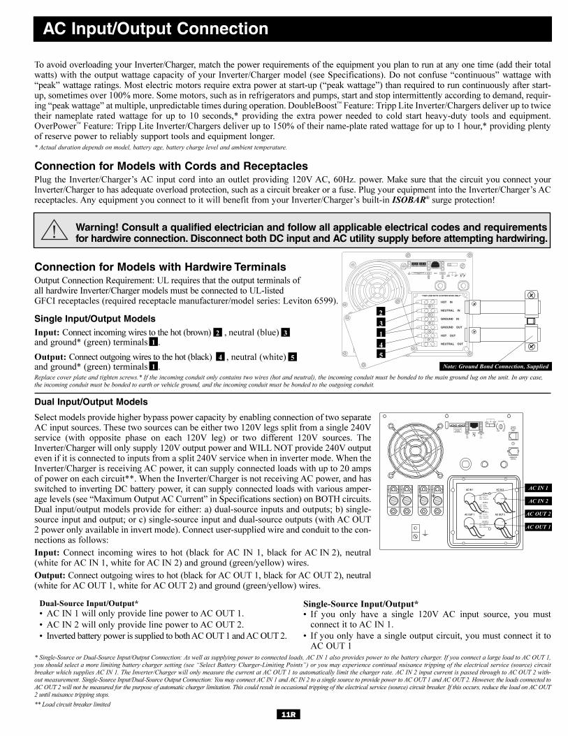
To avoid overloading your Inverter/Charger, match the power requirements of the equipment you plan to run at any one time (add their totalwatts) with the output wattage capacity of your Inverter/Charger model (see Specifications). Do not confuse “continuous” wattage with“peak” wattage ratings. Most electric motors require extra power at start-up (“peak wattage”) than required to run continuously after start-up, sometimes over 100% more. Some motors, such as in refrigerators and pumps, start and stop intermittently according to demand, requir-ing “peak wattage” at multiple, unpredictable times during operation. DoubleBoost™ Feature: Tripp Lite Inverter/Chargers deliver up to twicetheir nameplate rated wattage for up to 10 seconds,* providing the extra power needed to cold start heavy-duty tools and equipment.OverPower™ Feature: Tripp Lite Inverter/Chargers deliver up to 150% of their name-plate rated wattage for up to 1 hour,* providing plentyof reserve power to reliably support tools and equipment longer.* Actual duration depends on model, battery age, battery charge level and ambient temperature.
Connection for Models with Cords and ReceptaclesPlug the Inverter/Charger’s AC input cord into an outlet providing 120V AC, 60Hz. power. Make sure that the circuit you connect yourInverter/Charger to has adequate overload protection, such as a circuit breaker or a fuse. Plug your equipment into the Inverter/Charger’s ACreceptacles. Any equipment you connect to it will benefit from your Inverter/Charger’s built-in ISOBAR® surge protection!
Warning! Consult a qualified electrician and follow all applicable electrical codes and requirementsfor hardwire connection. Disconnect both DC input and AC utility supply before attempting hardwiring.
Connection for Models with Hardwire TerminalsOutput Connection Requirement: UL requires that the output terminals of all hardwire Inverter/Charger models must be connected to UL-listedGFCI receptacles (required receptacle manufacturer/model series: Leviton 6599).
Single Input/Output ModelsInput: Connect incoming wires to the hot (brown) , neutral (blue) and ground* (green) terminals .
Output: Connect outgoing wires to the hot (black) , neutral (white) and ground* (green) terminals .Replace cover plate and tighten screws.* If the incoming conduit only contains two wires (hot and neutral), the incoming conduit must be bonded to the main ground lug on the unit. In any case,
the incoming conduit must be bonded to earth or vehicle ground, and the incoming conduit must be bonded to the outgoing conduit.
Dual Input/Output Models
Select models provide higher bypass power capacity by enabling connection of two separateAC input sources. These two sources can be either two 120V legs split from a single 240Vservice (with opposite phase on each 120V leg) or two different 120V sources. TheInverter/Charger will only supply 120V output power and WILL NOT provide 240V outputeven if it is connected to inputs from a split 240V service when in inverter mode. When theInverter/Charger is receiving AC power, it can supply connected loads with up to 20 ampsof power on each circuit**. When the Inverter/Charger is not receiving AC power, and hasswitched to inverting DC battery power, it can supply connected loads with various amper-age levels (see “Maximum Output AC Current” in Specifications section) on BOTH circuits.Dual input/output models provide for either: a) dual-source inputs and outputs; b) single-source input and output; or c) single-source input and dual-source outputs (with AC OUT2 power only available in invert mode). Connect user-supplied wire and conduit to the con-nections as follows:
Input: Connect incoming wires to hot (black for AC IN 1, black for AC IN 2), neutral(white for AC IN 1, white for AC IN 2) and ground (green/yellow) wires.
Output: Connect outgoing wires to hot (black for AC OUT 1, black for AC OUT 2), neutral(white for AC OUT 1, white for AC OUT 2) and ground (green/yellow) wires.
* Single-Source or Dual-Source Input/Output Connection: As well as supplying power to connected loads, AC IN 1 also provides power to the battery charger. If you connect a large load to AC OUT 1,
you should select a more limiting battery charger setting (see “Select Battery Charger-Limiting Points”) or you may experience continual nuisance tripping of the electrical service (source) circuit
breaker which supplies AC IN 1. The Inverter/Charger will only measure the current at AC OUT 1 to automatically limit the charger rate. AC IN 2 input current is passed through to AC OUT 2 with-
out measurement. Single-Source Input/Dual-Source Output Connection: You may connect AC IN 1 and AC IN 2 to a single source to provide power to AC OUT 1 and AC OUT 2. However, the loads connected to
AC OUT 2 will not be measured for the purpose of automatic charger limitation. This could result in occasional tripping of the electrical service (source) circuit breaker. If this occurs, reduce the load on AC OUT
2 until nuisance tripping stops.
** Load circuit breaker limited
11R
1
2 3
4 5
AC Input/Output Connection
HOT IN
NEUTRAL IN
GROUND IN
GROUND OUT
HOT OUT
“FOR USE WITH COPPER WIRE ONLY”
NEUTRAL OUT
AC IN 1
HOT - BROWN NEU - BLUEGND - GRN/YEL
AC IN 2
HOT - GRAY NEU - WHITEGND - GRN/YEL
AC OUT 1
HOT - BLACK NEU - YELLOWGND - GRN/YEL
AC OUT 2
HOT - ORANGE NEU - REDGND - GRN/YEL
2
3
1
4
5
Note: Ground Bond Connection, Supplied
AC IN 1
AC IN 2
AC OUT 2
AC OUT 1
1
Dual-Source Input/Output*
• AC IN 1 will only provide line power to AC OUT 1.
• AC IN 2 will only provide line power to AC OUT 2.
• Inverted battery power is supplied to both AC OUT 1 and AC OUT 2.
Single-Source Input/Output*• If you only have a single 120V AC input source, you must
connect it to AC IN 1.
• If you only have a single output circuit, you must connect it toAC OUT 1
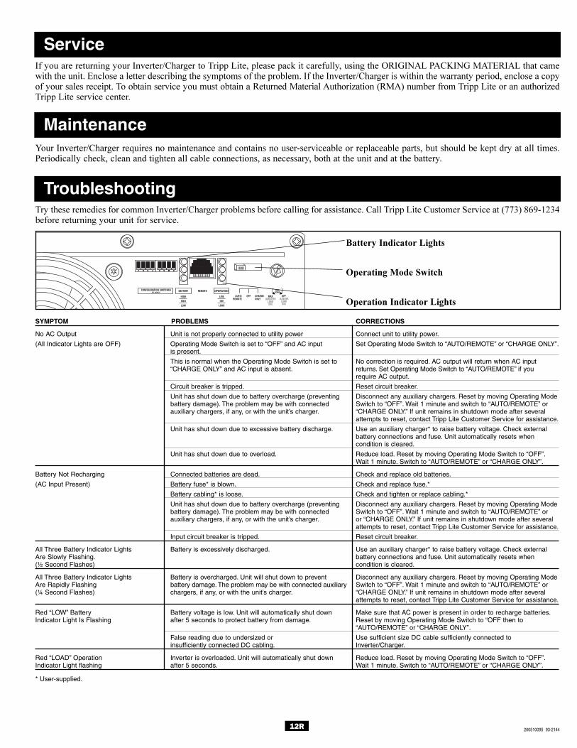
12R
ServiceIf you are returning your Inverter/Charger to Tripp Lite, please pack it carefully, using the ORIGINAL PACKING MATERIAL that camewith the unit. Enclose a letter describing the symptoms of the problem. If the Inverter/Charger is within the warranty period, enclose a copyof your sales receipt. To obtain service you must obtain a Returned Material Authorization (RMA) number from Tripp Lite or an authorizedTripp Lite service center.
Your Inverter/Charger requires no maintenance and contains no user-serviceable or replaceable parts, but should be kept dry at all times.Periodically check, clean and tighten all cable connections, as necessary, both at the unit and at the battery.
Try these remedies for common Inverter/Charger problems before calling for assistance. Call Tripp Lite Customer Service at (773) 869-1234before returning your unit for service.
Maintenance
Troubleshooting
SYMPTOM PROBLEMS CORRECTIONS
No AC Output Unit is not properly connected to utility power Connect unit to utility power.
(All Indicator Lights are OFF) Operating Mode Switch is set to “OFF” and AC input Set Operating Mode Switch to “AUTO/REMOTE” or “CHARGE ONLY”.is present.
This is normal when the Operating Mode Switch is set to No correction is required. AC output will return when AC input “CHARGE ONLY” and AC input is absent. returns. Set Operating Mode Switch to “AUTO/REMOTE” if you
require AC output.
Circuit breaker is tripped. Reset circuit breaker.
Unit has shut down due to battery overcharge (preventing Disconnect any auxiliary chargers. Reset by moving Operating Modebattery damage). The problem may be with connected Switch to “OFF”. Wait 1 minute and switch to “AUTO/REMOTE” orauxiliary chargers, if any, or with the unit’s charger. “CHARGE ONLY.” If unit remains in shutdown mode after several
attempts to reset, contact Tripp Lite Customer Service for assistance.
Unit has shut down due to excessive battery discharge. Use an auxiliary charger* to raise battery voltage. Check externalbattery connections and fuse. Unit automatically resets whencondition is cleared.
Unit has shut down due to overload. Reduce load. Reset by moving Operating Mode Switch to “OFF”.Wait 1 minute. Switch to “AUTO/REMOTE” or “CHARGE ONLY”.
Battery Not Recharging Connected batteries are dead. Check and replace old batteries.
(AC Input Present) Battery fuse* is blown. Check and replace fuse.*
Battery cabling* is loose. Check and tighten or replace cabling.*
Unit has shut down due to battery overcharge (preventing Disconnect any auxiliary chargers. Reset by moving Operating Modebattery damage). The problem may be with connected Switch to “OFF”. Wait 1 minute and switch to “AUTO/REMOTE” orauxiliary chargers, if any, or with the unit’s charger. or “CHARGE ONLY.” If unit remains in shutdown mode after several
attempts to reset, contact Tripp Lite Customer Service for assistance.
Input circuit breaker is tripped. Reset circuit breaker.
All Three Battery Indicator Lights Battery is excessively discharged. Use an auxiliary charger* to raise battery voltage. Check externalAre Slowly Flashing. battery connections and fuse. Unit automatically resets when(½ Second Flashes) condition is cleared.
All Three Battery Indicator Lights Battery is overcharged. Unit will shut down to prevent Disconnect any auxiliary chargers. Reset by moving Operating ModeAre Rapidly Flashing battery damage. The problem may be with connected auxiliary Switch to “OFF”. Wait 1 minute and switch to “AUTO/REMOTE” or(¼ Second Flashes) chargers, if any, or with the unit’s charger. “CHARGE ONLY.” If unit remains in shutdown mode after several
attempts to reset, contact Tripp Lite Customer Service for assistance.
Red “LOW” Battery Battery voltage is low. Unit will automatically shut down Make sure that AC power is present in order to recharge batteries.Indicator Light Is Flashing after 5 seconds to protect battery from damage. Reset by moving Operating Mode Switch to “OFF then to
“AUTO/REMOTE” or “CHARGE ONLY”.
False reading due to undersized or Use sufficient size DC cable sufficiently connected to insufficiently connected DC cabling. Inverter/Charger.
Red “LOAD” Operation Inverter is overloaded. Unit will automatically shut down Reduce load. Reset by moving Operating Mode Switch to “OFF”.Indicator Light flashing after 5 seconds. Wait 1 minute. Switch to “AUTO/REMOTE” or “CHARGE ONLY”.
* User-supplied.
OFF(LESSER
LOADON)
MAX(GREATER
LOADON)
Battery Indicator Lights
Operating Mode Switch
Operation Indicator Lights
200510095 93-2144