Intruder alarm system Engineering Information 6 Security zones PA input Tamper input Outputs for...
28
Intruder alarm system Engineering Information LGSIX/01 Logic Six panel with two pre learnt Keyfobs The above intruder system is designed to comply with the installation requirements of BS 4737 1986/87. 4188-753 issue 1_1/03 1 Accenta /! Learn Error Day 1 2 3 4 5 6 TA PA Power ZONE
-
Upload
nguyenkiet -
Category
Documents
-
view
215 -
download
0
Transcript of Intruder alarm system Engineering Information 6 Security zones PA input Tamper input Outputs for...

Intruder alarm system
Engineering Information
LGSIX/01 Logic Six panel with two pre learnt
Keyfobs
The above intruder system is designed to complywith the installation requirements ofBS 4737 1986/87.
4188-753 issue 1_1/03 1
Accenta�� mini
Learn
Error
Day
1 2 3 4 5 6 TA PAPower
ZONE
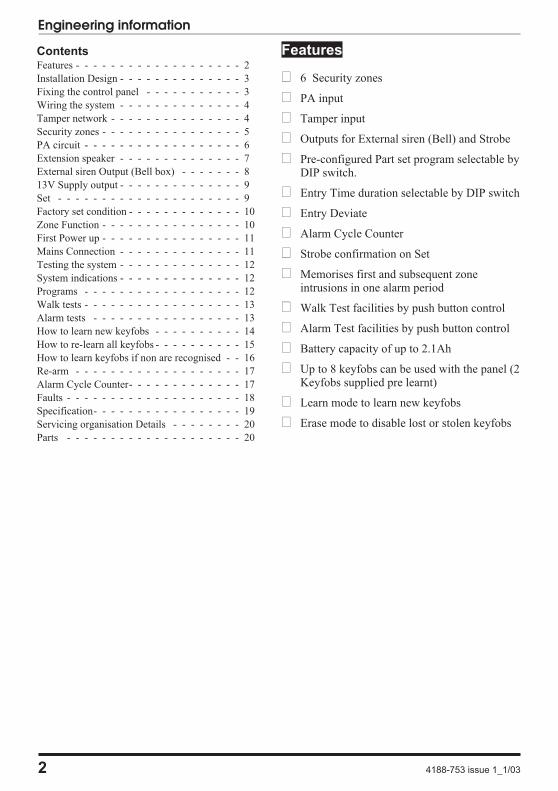
Features
� 6 Security zones
� PA input
� Tamper input
� Outputs for External siren (Bell) and Strobe
� Pre-configured Part set program selectable byDIP switch.
� Entry Time duration selectable by DIP switch
� Entry Deviate
� Alarm Cycle Counter
� Strobe confirmation on Set
� Memorises first and subsequent zoneintrusions in one alarm period
� Walk Test facilities by push button control
� Alarm Test facilities by push button control
� Battery capacity of up to 2.1Ah
� Up to 8 keyfobs can be used with the panel (2Keyfobs supplied pre learnt)
� Learn mode to learn new keyfobs
� Erase mode to disable lost or stolen keyfobs
2 4188-753 issue 1_1/03
Engineering information
ContentsFeatures - - - - - - - - - - - - - - - - - - - 2
Installation Design - - - - - - - - - - - - - - 3
Fixing the control panel - - - - - - - - - - - 3
Wiring the system - - - - - - - - - - - - - - 4
Tamper network - - - - - - - - - - - - - - - 4
Security zones - - - - - - - - - - - - - - - - 5
PA circuit - - - - - - - - - - - - - - - - - - 6
Extension speaker - - - - - - - - - - - - - - 7
External siren Output (Bell box) - - - - - - - 8
13V Supply output - - - - - - - - - - - - - - 9
Set - - - - - - - - - - - - - - - - - - - - - 9
Factory set condition - - - - - - - - - - - - - 10
Zone Function - - - - - - - - - - - - - - - - 10
First Power up - - - - - - - - - - - - - - - - 11
Mains Connection - - - - - - - - - - - - - - 11
Testing the system - - - - - - - - - - - - - - 12
System indications - - - - - - - - - - - - - - 12
Programs - - - - - - - - - - - - - - - - - - 12
Walk tests - - - - - - - - - - - - - - - - - - 13
Alarm tests - - - - - - - - - - - - - - - - - 13
How to learn new keyfobs - - - - - - - - - - 14
How to re-learn all keyfobs - - - - - - - - - - 15
How to learn keyfobs if non are recognised - - 16
Re-arm - - - - - - - - - - - - - - - - - - - 17
Alarm Cycle Counter- - - - - - - - - - - - - 17
Faults - - - - - - - - - - - - - - - - - - - - 18
Specification- - - - - - - - - - - - - - - - - 19
Servicing organisation Details - - - - - - - - 20
Parts - - - - - - - - - - - - - - - - - - - - 20
Installation Design
The purchase of this alarm system represents amajor step forward in the protection of theproperty and its occupants. It is important to planthe installation before proceeding following theprocedures and advice contained in this manual.
Plan the position of each part ofthe alarm system and the cableruns. Detectors should be sitedwith particular regard to thedegree of coverage required
and the function of each of the zones.
All of the system wiring isconnected directly to the panel.The intruder panel must beinstalled near an entry/exitpoint.
One additional internal sound
speaker is recommended, itwill provide high volume alarmtones and low volumeentry/exit tones. Speakers
should be positioned to provide good sounddistribution throughout the building and so thatthe exit tone is audible outside the main entry /exit door. This will enable the system operatorto check that the system is setting correctly.
Finally note that the total
current output of this controlsystem (in alarm condition) is1A when supported by a fullycharged battery. Calculate the
total current consumption of every part of thesystem including the panel, external siren withstrobe light (bell box) and detectors to ensurethat this rating is not exceeded.
Depending on which area youlive, you may be required, bylaw to notify the Local
Authority and Police of thenew security alarm
installation. The local authority requirementsmay differ from area to area, therefore it isadvisable to contact local environmental officerto obtain full details of your area requirements.
Fixing the control panel
Caution: When positioning the controlpanel ensure that it is located in a dryplace away from damp areas.
a. Remove the front cover(s) from thebase assembly.
Disconnect the transformer wires fromthe board, these are marked AC.Carefully remove the board by gentlypushing down the holding clips on thebottom edge of the board and withdrawit from the base.
Note: When replacing the board align iton the round support pillars to the bottomand allow it to click down past the clipsat the top of the case. Refit thetransformer wires into the terminal.
4188-753 issue 1_1/03 3
Logic Six intruder system
�
�
�
ZONES
Power
Error
Day1 2 3 4 5 6 TA PA
Learn
LA
ITOTAL
Power
�
� �

b. Fit the panel to the wall with suitablefixings. Ensure the wall surface is flat toprevent base distortion. There arecable entry holes provided in the rearof the base and around the outsideedges through the thinned out plasticsections which may be cut away asrequired.
c. The hole provided adjacent to themains transformer is a dedicated mainscable entry point.
Board
There are three fuses mounted on the circuitboard, all are 20mm quick blow.
F1 1.6A - to protect the +ve line of 12V battery
F3 1A - to protect the Speaker 13V supply
F5 1A - to protect the Siren & Strobesupply
As supplied, there are wire links are fitted acrossthe PA and Tamper terminals to represent aclosed circuit.
Wiring the system
Caution: Always power-down the panelwhen wiring external circuits, to preventdamage to the panel electronics.
Systematically wire and test each circuit:
� Zones, Tamper and PA circuits
� Finish by wiring any additional extensionspeaker sounders, external siren (bell) /strobe and the 13V supply.
Tamper network
The Tamper circuit is used to protect all cablesand detectors in the system from unauthorisedaccess including the panel cover.
The zone and PA tampers should be series wiredand connected to the TAMP terminals. Theterminals T & A are for the external sirentamper. Tamper alarms that occur in the Daymode operate internal sounders only. Tamperalarms in Set cause a full alarm condition.Tamper is indicated by the Tamper TA
indicator.
4 4188-753 issue 1_1/03
Engineering information
J2
PA+
TAMP-
+13V 0V -STROBE
J6
+ - AC
SW1
+ T ASCB
D BBELL
+ -
SET+ve 1A 1A 1.6A
BE
LL
/ST
RO
BE
13
V/
SP
EA
KE
R
BA
TT
ER
Y
BATT
J4
F1F3F5
VR1
VOLUME
21 43 65
Factory fitted links
LD2 LD8 LD9 LD4 LD10 LD5 LD11 LD23
LD12
LD22
LD6
J1
LD3
SW2
WALK /ALARM TEST
TAMPON
OFF
EN
TR
YT
IME
PA
RT
SE
T
15S
30S
Mounting holes
Mounting holes
Cable entryholes
DangerHigh Voltage
~ 230V 50Hz 0.2A
FUSE T125mA 250V(ANTI-SURGE)

Security zones
Note: The panel is supplied with wire links for unused zones. All unused zones musthave links fitted to disable the zone.
It is recommended that no more than 10 magnetic contacts are connected to the same zone.
4188-753 issue 1_1/03 5
Logic Six intruder system
J2
21 43 65
Panel
Alarm
+ -
PA+ -
TAMP +13V 0V
PIR
All unused zonesmust have links fittedto disable the zone.
Board
PIR
DoorContact
DoorContact
Terminal blockis not supplied
Tamp
J1

PA circuit
Any quantity of normally closed type personal attack button may be wired in series and thenconnected to the PA circuit.
Operational in Day and Set, the PA circuit will cause a full alarm condition when activated. PA isindicated on the control panel as PA.
PA buttons may be fitted near the front door, or in a bedroom.
6 4188-753 issue 1_1/03
Engineering information
PA+ -
TAMP +13V 0V
Board
Panel
PanicButton
PanicButton
J2
21 43 65
J1

Extension speaker
Extension speaker may be connected to the loudspeaker terminals to produce high volume alarmtones and low volume entry / exit fault tones.
A 16 ohms extension speaker may be wired across the speaker terminals. Mounted in convenientposition within the installation the extension speaker will reproduce all of the alarm tones generatedby the control panel.
A control marked VOLUME in the centre of the board may be used to adjust the low volumeentry/exit tones to suit environmental conditions.
4188-753 issue 1_1/03 7
Logic Six intruder system
-STROBE
J6
+ T ASCB
D BBELL
+ -
SET+ve 1A
BE
LL
/ST
RO
BE
F5
Panel
Board
1A
13
VS
PE
AK
ER
F3
16 Ohms Extension Speaker
VR1
VOLUME

External siren Output (Bell box)
The external siren (bell box) is usually installed in a high position from where the siren could beseen and heard.
Terminal T A D B are for connecting to the external siren. These terminals provide apower/hold-off supply, sounder trigger and tamper circuit to protect the external siren housing.
The terminals are summarised as follows:
T - -Ve tamper return
A - -Ve supply (0V)
D - +Ve supply (12V)
B- -Ve Sounder trigger
For ease of installation, ADE external sirens and modules use the same markings.
Where a discrete external siren is used, it should be connected to terminals D & B. Terminals T & Aare then used for tamper protection for the housing.
8 4188-753 issue 1_1/03
Engineering information
-STROBE
J6
+ T ASCB
D BBELL
+ -
SET+ve 1A
BE
LL/S
TR
OB
E
F5
Sonade
Panel
Board
+ - T E A D BSTROBE

Where self contained / powered sounders are used, carefully follow the manufacturers instructions,match each of the terminals to those above.
13V Supply output
The 13V output is to power detectors which require a voltage supply (PIR detectors etc). The supplyis present at all times and may be used to supply a total load of 350mA.
Set +VE
The output , marked SET +VE is used with latching detectors. The output becomes positive oncorrect Set of the system and is removed on UNSETTING the system.
4188-753 issue 1_1/03 9
Logic Six intruder system
# Terminal blockis not supplied
-STROBE
J6
+ T ASCB
D BBELL
+ -
SET+ve 1A
BE
LL/S
TR
OB
E
F5
Sonade
Panel
Board
+ - T E A D BSTROBE
#
Sonade
+ - T E A D BSTROBE

Factory set condition
Keyfob 1 and 2 (supplied) - Learnt
Keyfobs 3 to 8 (optional) - - Require learning
External siren Bell Duration 20 minutes
External siren Bell Delay - - No delay
Full Set
Zone1 - - - - - - - - - Timed
Zone 2- - - - - - - - - Time inhibited
Zone 3, 4, 5 & 6 - - - - Immediate
Entry time (timed zone)- 30seconds(default)(15 seconds via setting DIP switch)
Exit mode is timed - - - 30 seconds
Part set (DIP switch selectable see page 12)
Zone 1, 2 & 3 - - - - - Timed
Zone 4- - - - - - - - - Immediate zone
Zone 5 & 6- - - - - - - Omitted zones
Entry time (timed zone)- 30seconds(default)(15 seconds via setting DIP switch)
Silent Exit mode is timed 30 seconds
Applicable for both full and part set:
Tamper TA 24 hour alarm
Personal Attack PA 24 hour alarm
Security Zones - - - - - - - Zones 1…6
Zone debounce period - - - 640mS ALL zones
Zone Function
The following are definitions of zone functions:
Timed : This function would be used to protectthe main entry/exit door of the entry route.
Time inhibited (Walk through) : This is a zonewhich, on setting the panel, allows access to theEntry / Exit zone. However, if the panel is setand an time inhibited zone is triggered before anEntry /Exit zone then an alarm will be generatedimmediately.
Immediate: This is a zone which will, whenentered, go into alarm when the panel is set.
The Entry deviate feature permits an immediatezone to be activated during the entry periodwithout causing a full alarm.
Unused : An unused zone that has been linkedout will be ignored by the panel.
10 4188-753 issue 1_1/03
Engineering information

First Power up
Before power up fit the top cover on to the baseand connect the speaker wires. Leave the coverin position throughout the reset of theinstallation.
a. Check that the factory fitted links areconnected to terminals unused Zones,PA, TAMP and T-A.
b. Fit the battery wires to the BATTterminals on the Board, Red to + andBlack to -.
c. On connecting the battery the systemwill now go into alarm condition, theTamper LED is lit and the Power LEDgives a flashing indication:
d. Fit the cover to hold down the tamperspring at the bottom centre of theboard.
e. Offer a keyfob to the centre depressionon the panel. Note the Tamper LEDand Alarm switches Off and the
LED is lit.
Note: If you do not withdraw the keyfobafter it is recognised by the panel thenyou run the risk of entering an undesiredmode of operation.
Mains Connection
The mains power should be connected using a
3 core cable of not less than 0.75mm sq. from afused spur to the mains connector inside thecontrol panel. The 2 A fused spur must belocated close to the control panel.
Note: The mains supply must beconnected by a technically competentperson and according to current IEEregulations.
Caution: To avoid the risk of electricalshock you must always totally isolate themains supply before opening the controlpanel cover(s).
� Mains Input Fuse rating: 125mA, 250V typeT (anti surge) and of a type approved to IEC127 part 2 sheet III.
On connecting the mains supply to the panel thepower indicator is lit.
(Changes from flashing to steady)
4188-753 issue 1_1/03 11
Logic Six intruder system
N
LE
Transformer
125mA Fuse
Panel
+ - AC1.6A
BA
TT
ER
Y
BATT
J4
F1 Board
(red)+
Black -
12V battery
TA
AlarmPower
Offer keyfobto the Paneland withdraw
Keyfob recognition beep
Accenta�� mini
1 2 3 4 5 6 TA PA
ZONE Learn
Error
Day
Power
N
LE
Transformer
125mA Fuse
Panel
+ - AC1.6AB
AT
TE
RY
BATT
J4
F1 Board
(red)+
Black -
12V battery
2A Fused Spur unit
Dedicated mains supplyfrom consumer unit.
Day
Power

Testing the system
Complete the wiring of the system and then:
� Program the panel.
� Fully test the system and ensure it is faultfree
� Fill in the installation log at the back of thismanual and retain if for future reference.
� Finally explain the operation of the systemto the end user. The Operating Instructions
are attached to the centre of this manual.
Detach them and leave them with the
user.
Key
System indications
- Unset system indication
- Set system indication
Note: The Power LED will give aflashing indication when there is a mainssupply failure to the panel.
Programs
The panel offers Full Set or selectable Part Setroutine and programmable entry time. As defaultthe panel is set for Full Set and an Entry time of30 seconds.
� Full Set : Arms all of the zones and becomeSet as the user leaves the property after theExit time of 30 seconds.
� Part Set : To protect the downstairs areas ofthe house at night the Zones 5 and 6 areomitted from being set as the user goesupstairs after the Exit time of 30 seconds.
Note: The Part Set assumes Zone 5and Zone 6 are upstairs zones.
� Entry time 30 seconds (factory default):Allows the user to enter the premises andunset the system within 30 seconds.
� Entry time 15 seconds : Allows the user toenter the premises and unset the systemwithin 15 seconds.
12 4188-753 issue 1_1/03
Engineering information
Power
Day Power
LED steady On indication
LED Off
Strobe
External Siren
NOTE: In general a flat beep isan indication of not recognised keyfobs.
Sound description
Internal sound
External devices
LED flashing indication
J6
ON
OFF
EN
TR
YT
IME
PA
RT
SE
T
15S
30S
Board
Panel
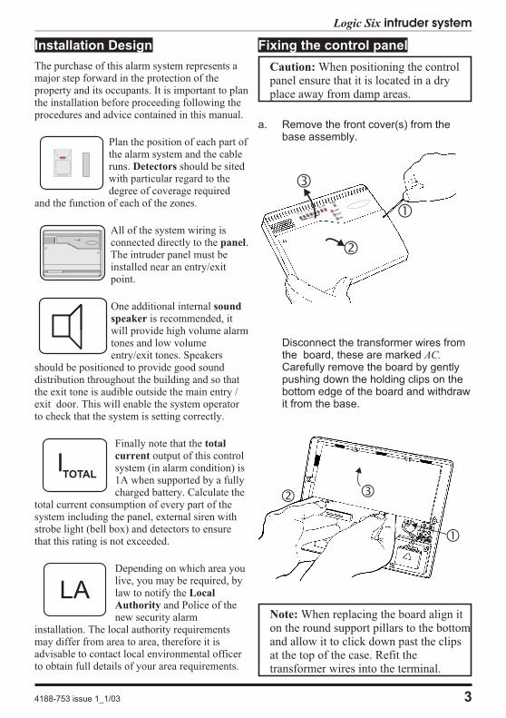
Walk tests
The walk test function allows each detector to bechecked in order to verify that they arefunctioning correctly.
To enter walk test the panel must be in Day
mode with the DAY LED lit:
a. Open the bottom cover of the panel.Note this will cause a tamper alarm.
b. Present a recognised keyfob and the
alarm sound stops. Tamper TALED will flash to give a tamperindication.
c. Momentarily press the PCB mountedpush button. Note do not hold thebutton down or it will go into Walk test.
The DAY LED starts to flash.
d. Upon activation of any zone, the
relevant ZONE led will latch up anda “Zone fault” tone is emitted.
e. Pressing the push button again at anytime will clear the latched LED andwalk test is restarted.
f. On completion of Walk Test, close thepanel cover and an “OK” tone isemitted and the panel returns to Day
mode with the Day LED lit.
Alarm tests
The alarm test function allows you to test theStrobe, Siren (Bell), Low and High volumesounders of the system, SET+ output.
The Alarm Test mode could also beactivated while in Walk Test mode, ifyou are doing this go straight to step d).
To enter Walk Test mode the panel must be in
Day mode with the DAY LED lit:
a. Ensure the bottom cover of the panel isopen. Note this will cause a tamperalarm.
b. Present a recognised keyfob and the
alarm sound stops. Tamper TALED will flash to give a tamperindication.
d. Press the PCB mounted push buttonand hold for 3 seconds.
e. The tests below are performedconsecutively. Automatic advance tothe next test after 3 seconds.1) Low Volume Sounders2) High Volume Sounders and Strobe3) External Bell and Strobe4) SET+ output and Strobe
f. On completion of Alarm Test an “OK”tone is emitted and the panel returns to
Day mode with the DAY LED lit.Close the bottom cover of the paneland the Tamper TA LED switches Off.
4188-753 issue 1_1/03 13
Logic Six intruder system
Board
Panel
SW2
WALK /ALARM TEST
Board
Panel
SW2
WALK /ALARM TEST

How to learn new keyfobs
14 4188-753 issue 1_1/03
Engineering information
Offer a slightly touch it on the centre depression ofthe A learnt indication is given of the when theflashing LED changes to steady On indication and thereis a recognition beep given by the local sounder.Shortly after the next numbered LED will start flashing.Withdraw the learnt keyfob.
You now have up to 10 seconds to learn another new keyfob.
For keyfobs 7 and 8 the indications are TA and PA LEDsrespectively.
new keyfobPanel. new keyfob
ZONE
ZONE
keyfob recognised beep
Panel
Newkeyfob
When an unrecognised keyfob is offered to the it will cause theLED to be lit and a continuous sound is emitted from the
local sounder.
Hold the
The will timeout after 10 seconds if no action is taken tolearn new keyfob
panelError
learn mode
recognised such that it touches the centredepression on the Panel and keep it there without movement for
You will hear a keyfob recognition beep andlater five rapid beeps from the local sounder.
You are now in the The LED will give a flashingindication and the LEDs change from flashing to steady Onindication to show recognised or . The is nowready to learn signalled by the nextflashing LED. Withdraw the keyfob.
In the when an already learnt keyfob is offered to thean Error indication will be given.
‘learnt’ keyfob
learnt keyfob Panelnew keyfobs
Panel,
10 seconds.10 seconds
learn mode. LearnZONE
ZONE
learn mode
1
Repeat to learn the
Once all the keyfobs are recognised ‘learnt’ by the wait forjust over 10 seconds for the Panel to exit the this isannounced by two beeps from the local sounderand return to mode indication.
new keyfob.
Panellearn mode,
Day
x 2 beeps
keyfob recognised beep
Panel
Learntkeyfob
x 5 rapid beeps
Hold for10 seconds
Power
Day
Using a recognised the can learn further keyfobs. A total of 8 keyfobs are recognisedby a Panel. You may want to do this if you have acquired additional keyfobs. Using these proceduresthe panel will still memorise previously learnt keyfobs. New k
learnt keyfob panel
eyfobs must be learnt by the .panel
Ensure the is in the day mode with the LED lit. You shouldhave one and the new keyfobs available.
panellearnt keyfob
Day
Indication given assumes
2 keyfobs were previously
learnt by the Panel
32
1 42 3
Learn
Power
Day
Learn

How to re-learn all keyfobs
4188-753 issue 1_1/03 15
Logic Six intruder system
By entering the in this manner you will erase allrecognition of previously learnt keyfobs at the Panel, except for theone used to enter the .
learn mode
learn mode
Offer the slightly touch it on the centre depression of theA learnt indication is given of the when the flashingLED changes to steady On indication and there is a recognitionbeep given by the local sounder. Shortly after the next numberedindicator will start flashing. Withdraw the learnt keyfob.
You now have up to 10 seconds to start learning another keyfob.
next keyfob Panel.next keyfob ZONE
ZONE
keyfob recognised beep
Panel
Nextkeyfob
When an unrecognised keyfob is offered to the it will causethe LED to be lit and continuous sound to beemitted from the local sounder.
Hold the
The will timeout after if no actions is takento learn the next keyfob
PanelError
learn mode 10 seconds
recognised slighty touching the centredepression on the and keep it there without movementfor . Initially you will hear a keyfob recognition beep and
later five rapid beeps from the local sounder. Afteranother you will hear 5 rapid beep tone from the localsounder. You are now in the The LED will give aflashing indication and the LED changes from flashing tosteady On indication to recognise the .The is now ready to learn the , signalled by the
LED flashing. Withdraw the learnt keyfob.
In the when an already learnt keyfob is offered to thean Error indication will be given.
‘learnt’ keyfobPanel
learnt keyfobPanel next keyfob
Panel,
20 seconds10 seconds
10 secondslearn mode. Learn
ZONE 1
ZONE 2
learn mode
Repeat to learn the
Once all the keyfobs are recognised ‘learnt’ by the wait for just over10 seconds for the Panel to exit the this is announced by twobeeps from the local sounder and return to mode indication.
next keyfob.
Panellearn mode,
Day
x 2 beeps
keyfob recognised beep
Panel
Learntkeyfob
x 5 rapid beeps
Hold for20 seconds
Using a recognised the can re-learn up to 8 keyfobs. You may want to do this aftera keyfob is lost or stolen and you want to prevent the use of it to operate the system.
learnt keyfob PanelKeyfobs must
be learnt by each installed in a systemPanel
Ensure the is in the day mode with the LED lit. You musthave one and up to 7 further keyfobs to be learnt. Haveall the keyfobs available.
Panellearnt keyfob
Day
x 5 rapid beeps
Power
Day
1 2 3
Learn
1 2
Learn
1 2 3
Learn
Power
Day

How to learn keyfobs if none are recognised
16 4188-753 issue 1_1/03
Engineering information
Offer the slightly touching it on the centre depressionof the A learnt indication is given of the whenthe flashing LED changes to steady On indicationand there is a recognition beep given by the local sounder.Shortly after the next numbered LED starts flashing.Withdraw the learnt keyfob.
next keyfobPanel. next keyfob
ZONE
ZONE
You now have up to to learn the10 seconds next keyfob.keyfob recognised beep
Panel
Nextkeyfob
Hold the slightly touching it on the centre depressionof the .
first keyfobPanel Once the is acknowledged by the
the LED changes from flashing to steady and there isa recognition beep given by the local sounder. Withdraw the learntkeyfob. The is now ready to learn the ,signalled by LED flashing.
first keyfob Panel
Panel next keyfob
ZONE 1
ZONE 2
keyfob recognised beep
Panel
firstkeyfob
x 5 rapid beeps
Now remove the link between Z1 and Set.
x 2 beeps
Hold
Ensure the is connected to the intruder system and thelink is fitted on the
Power up the intruder system you will hear five rapid beeps toacknowledge the is in the .
PanelPanel PCB between Z1 and Set.
Panel Learn mode
The will NOT timeout until the first keyfob is learnt.learn mode
You will only need to learn keyfobs in this manner if no keyfobs are recognised by theYou must have all the keyfobs to be
learnt available. Keyfobs can be learnt by each installed in a system
Panel.
Panel
A canlearn up to 8 keyfobs following power up of the intruder system.
Panel
POWER UP THE SYSTEM
Power
Day
1
Learn
1ZONE
-STROBE
J6
+ T ASCB
D BBELL
+ -
SET
1 2
Learn
1
Learn
2 3
Repeat to learn the next keyfob.
Once all the keyfobs are recognised ‘learnt’ by the Panel waitfor just over and the Panel will exit the10 seconds learn mode,this is announced by two beeps from the local sounder and returnto Day mode indication.

NVM Error
A Non Volatile Memory NVM error indicationis given by a flashing Error LED. If an NVMerror occurs then you will need to re-learn all thekeyfobs, see page 16.
Re-arm
After an alarm the panel will automatically resetitself when the external siren (bell box) 20minute timer has expired.
Alarm Cycle Counter
An alarm cycle is considered as the duration ofan alarm from trigger to the end of 20 minutesoperation of the external siren. The panel allowsthree alarm cycles during either set or unsetperiod. When the third alarm cycle expires thepanel is shut down, the storobe continues tooperate. The panel is unset in the normal waysee operating instructions.
4188-753 issue 1_1/03 17
Logic Six intruder system
Faults
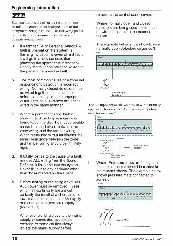
Fault conditions are often the result of minorinstallation errors or misinterpretation of theequipment being installed. The following pointsoutline the most common installation andcommissioning faults.
a. If a tamper TA or Personal Attack PAfault is present on the system, aflashing indication is given of first fault,it will go to a lock out condition(showing the appropriate indication).Rectify the fault and offer the keyfob tothe panel to remove the fault.
b. The most common cause of a zone notresponding to detection is incorrectwiring. Normally closed detectors mustbe wired together in a series loopbefore connecting into the appropriateZONE terminals. Tampers are serieswired in the same manner.
c. Where a permanent zone fault isshowing and the loop resistance isfound to be in order, the most probablecause is a short circuit between thezone wiring and the tamper wiring.When measured with a multimeter theseries resistance between the zoneand tamper wiring should be infinitelyhigh.
d. If totally lost as to the cause of a fault,remove ALL wiring from the Board.Refit the 9-links and test the system.Never fit links to any positions otherthan those marked on the Board.
e. Before testing or replacing any fuses,ALL power must be removed. Fuseswhich fail continually are almostcertainly the result of a short circuit orlow resistance across the 13V supplyor external siren (bell box) supply(terminal D).
Whenever working close to the mainssupply or connector, you shouldexercise extreme caution alwaysisolate the mains supply before
removing the control panel covers.
Where normally open and closeddetectors are being used these mustbe wired to a zone in the mannershown.
The example below shows how to wirenormally open detectors on zones 3.
The example below shows how to wire normallyopen detector on zones 3 and a normally closeddetector on zone 4.
f. Where Pressure mats are being usedthese must be connected to a zone inthe manner shown. The example belowshows pressure mats connected tozones 3.
18 4188-753 issue 1_1/03
Engineering information
J2
21 43 65 PA+ -
TAMP +13V 0V
Board
J1
Panel
Normally opendetectors
J2
21 43 65 PA+ -
TAMP +13V 0V
Board
J1
Panel
Normally opendetectors
Normally closeddetector
J2
21 43 65 PA+ -
TAMP +13V 0V
Board
J1
Panel
Pressure Mats

Specification
Indicators onControl panel
Zone 1-6 (red), Tamper -TA (amber), PersonalAttack-PA, Power, Learn(amber), Error (red) andDay (green)
6 Zones +ve loop, Security zones
Tamper -ve loop, always active
PA +ve loop, always active
User keyfobs Up to 8 keyfobs can belearnt to operate with thepanel
Keyfob operatingrange
20mm nominal formcentre depression
Proximity reader 125KHz inductive
External siren(Bell box) Output
12V, time 20 minutescontinuous
Strobe Output 12V latching
Extension Speaker 16 Ohms 260mA
Exit time 30 seconds
Entry time Programmable by DIPswitch 15 seconds or30 seconds
Full/Part Set Programmable by DIPswitch
Walk and AlarmTests
Selectable by pushbutton switch
Zone Input Delay 640mS
Set +ve Output 0V in Day (sinking40mA)
12V in Set (Sourcing10mA)
CurrentConsumptionControl panel
Standby 80mA
Alarm 250mA
Low voltageoutput
13.8V dc stabilised(+/-5%) up to 350mA
RechargeableBattery
12V, 1.2 or 2.1Ah
Charge Voltage 13.8V dc (+/-5%)
Board Fuses 1.6A & 1A 20mm quickblow
Mains Input fuse 125mA, 250V type T(anti-surge) typeapproved to IEC 127,part 2 sheet III
Total CurrentOutput
1A when supported by afully charged battery
Mains SupplyVoltage
230V (+/-10%) 50Hzmax load 0.2A
AmbientOperatingtemperature
0°C to 40°C
Enclosureconstruction
3mm Polycarbonate
Panel dimension H 200mm W 253mmD 55mm
Keyfob dimension L 58.5mm W 18.5mm
4188-753 issue 1_1/03 19
Logic Six intruder system

Servicing organisation Details
Servicing organisation name:
_______________________________________
Telephone number:
______________________________________
Date of installation:
______________________________________
Account Number:
_____________________________________
Parts
Below is a list of approved parts and accessories.
LGSIX/01 Logic Six panel(supplied with 2 learnt keyfobs)
SS/F Spare Keyfob
20 4188-753 issue 1_1/03
Engineering information
The Logic Six panel conforms to therequirements of the European R&TTE directive1999/5/EC and carries the CE mark. Thisproduct is intended for use in the UK.
For Technical Support
� : 01268 563270
ED&S
The Arnold Centre
Paycocke Road
Basildon Essex
SW14 3EA
Resistance Area protection and equipment used (eg PIR, Contacts..)
Zone 1
Zone 2
Zone 3
Zone 4
Zone 5
Zone 6

Intruder alarm system
Operating Instructions
Servicing organisation details
Servicing organisation (Installer) name: ______________________________________________
Telephone number: _______________________________________________________________
Date of installation: _______________________________________________________________
Account number: _________________________________________________________________
1
Accenta�� mini
Learn
Error
Day
1 2 3 4 5 6 TA PAPower
ZONE

System installation
This booklet tells you how to operate yourintruder alarm system. To simplify this bookletwe have assumed that the alarm system has beeninstalled by a professional intruder alarm systeminstaller (the installer), and that the system isoperated in a “typical” way. Aspects of yoursystem that are not “typical” will be describedby your installer.
Note: If you have any questions aboutyour intruder system, then consultyour installer, see contact details onthe front page.
Keyfobs
To operate the alarm system you will need thekeyfobs supplied with the panel. These keyfobsare recognised by the panel and will operateyour system. If you should need further keyfobsyou should consult your installer, up to8 maximum keyfobs can operate your system.
2
Operating instructions
KeyfobsSuppliedwith the panel
Additionalkeyfobs

Personal Attack
If you are under threat, or are being attacked,you can activate the alarm by operating thepersonal attack buttom in your system. Thealarm system will produce a loud alarm sound,and the external siren will be turned on.
Power Indicator
The Power indicator on the control panel willlight whenever the mains power supply ispresent. If mains power fails then the Power
indicator will flash, but the system will run fromits backup battery for several hours. If the Power
indicator goes out when mains power is presentthen a fault may have developed on your systemand you should contact your installer.
Key
3
Logic Six intruder system
LED steady On indication
LED Off
Strobe On
External Siren
NOTE: In general a flat beep isan indication of not recognised keyfobs.
Sound description
Internal sound
External devices
LED flashing indication

How to Set the system
When you leave your premises you will need to set (or turn on) the intruder alarm system. Beforesetting the system you should ensure that the premises have been completely vacated and that alldoors and windows are closed. Ensure that pets do not have access to the protected areas as theycan cause a false alarm, unless pet immune detectors have been used, ask your installer for moreinformation.
4
Operating instructions
PanelOffer keyfobto the Paneland withdraw
Keyfob recognition beep
The indicator should be lit at the Panel.Offer a to the Panel and withdraw itas soon as you hear the
from the local sounder.
The system will produce the exit beeptone and you should leave the premises bythe exit route recommended by your installer.The system will set when the exit beep tonestops.
Daykeyfob
keyfob recognitionbeep tone
Note the panel LEDs will flash consecutivelyfrom right to left, PA to Zone1 LED during Setoperation. If however there is an open zonethen the relevant ZONE LED will be lit and asound indication is given. If this is the casethen investigate the cause and ensure allzones are closed.
Insistent Exit beeps
(for final 10 seonds)
Once any operation is performedusing the keyfob withdraw it awayfrom the panel, wait forduration before next use of thekeyfob to operate the system.
3 seconds
Power
Day
Power
The external strobe will operate for ,which provides a confirmation of SET operation.
5 secondsExit beep
1 2 3 4 5 6 TA PA
ZONE
How to Unset the system
When you enter your premises you will need to unset (or turn off) the system. If your system hadgone into alarm then be aware that intruders may be in the premises. Seek assistance beforeinvestigating the cause of the alarm and unset the system.
5
Logic Six intruder system
PanelOffer keyfobto the Paneland withdraw
Keyfob recognition beep
Enter your premises by the route recommendedby your installer. The system will produce anentry beep tone.
Offer a to the Panel and withdraw it assoon as you hear the beeptone from the local sounder.
The system will stop the entry beep tone andlight the green LED.
If any Zone, Tamper or Attack LEDs lightup then an alarm has occurred, and an intrusionmay have taken place. Seek assistance beforeinvestigating further as intruders may still beon the premises. The first alarm indicationgiven by a flashing indicator, with all subsequentalarm indication given as a steady indication.These indications will remain until the next timethe system is unset.
keyfobkeyfob recognition
Day
Note the panel LEDs will flash consecutivelyfrom left to right, from to the LED,during Unset operation.
Zone1 PA
Entry beep
Day
Power
n
Day
TA PA
Power
1 2 3 4 5 6 TA PA
ZONE

How to part set the system
If your installer has programmed your system for part set operation you will be able to set somezones of the system while others remain unset. Part set operation is often used at night time, and itwill permit you to freely walk around the bedrooms while the living area and outside doors areprotected.
Before part setting the system at night time you should ensure the downstairs of the premises havebeen completely vacated and that all doors and windows are closed. Ensure that pets do not haveaccess to the protected areas as they can cause a false alarm.
6
Operating instructions
Panel
Within10 seconds offer keyfobsecond time to the Paneland withdraw
Keyfob recognition beep
The indicator should be lit at the Panel.Offer a to the Panel and withdraw itas soon as you hear the
from the local sounder.Ensure ZONE 1 to ZONE 4 LEDs are Off.If they remain On, investigate the cause andensure the zones are closed.The system will produce the exit beeptone. Within 10 seconds o
and you shouldnow move to area omitted by part set.
The system will set after 30 seconds when twoconsecutive beep is emitted.
Daykeyfob
keyfob recognitionbeep tone
ffer a asecond time to the Panel and withdraw it,you hear another
from the local sounder
The indicator should be flashing at the Panel.
keyfob
keyfob recognition beeptone
Day
Exit beep
Once a any operation is performedusing the keyfob withdraw it awayfrom the panel, wait for 3 secondsduration before next use of thekeyfob to operate the system.
Power
Day
Power
PanelOffer keyfobto the Paneland withdraw
Day
2 x Set beep when panel is set

Entry time:________________
Areaprotected
Zone name Full set Part Set
Zone 1 T T
Zone 2 TI T
Zone 3 I T
Zone 4 I I
Zone 5 I O
Zone 6 I O
O = Omited
T = Timed (Entry/Exit - Zone)
TI = Time Inhibited (Access zone to keypad)
I = Immediate (Zone armed to give full alarm)
7
Logic Six intruder system

8 4188-753 issue 1_1/03
Operating instructions
The Logic Six panel conforms to therequirements of the European R&TTE directive1999/5/EC and carries the CE mark. Thisproduct is intended for use in the UK.


![MB81EDS516545 - Fujitsu...CK, CK Input Clock CKE Input Clock Enable CS Input Chip Select RAS Input Row Address Strobe CAS Input Column Address Strobe WE Input Write Enable BA[1:0]](https://static.fdocuments.in/doc/165x107/60e98dfc20357b2d2330df42/mb81eds516545-fujitsu-ck-ck-input-clock-cke-input-clock-enable-cs-input-chip.jpg)