Introduction to MSP430 Communication · PDF fileIntroduction to MSP430 Communication...
32
© 2006 Texas Instruments Inc, Slide 1 Introduction to MSP430 Communication Interfaces Christian Hernitscheck MSP430 FAE Europe Texas Instruments
Transcript of Introduction to MSP430 Communication · PDF fileIntroduction to MSP430 Communication...
© 2006 Texas Instruments Inc, Slide 1
Introduction to MSP430 Communication Interfaces
Christian HernitscheckMSP430 FAE Europe
Texas Instruments
© 2006 Texas Instruments Inc, Slide 2
• USART, USCI, USI Comparison• RS232 Communication • SPI Communication• I2C Communication• Lab Activities
Agenda
© 2006 Texas Instruments Inc, Slide 3
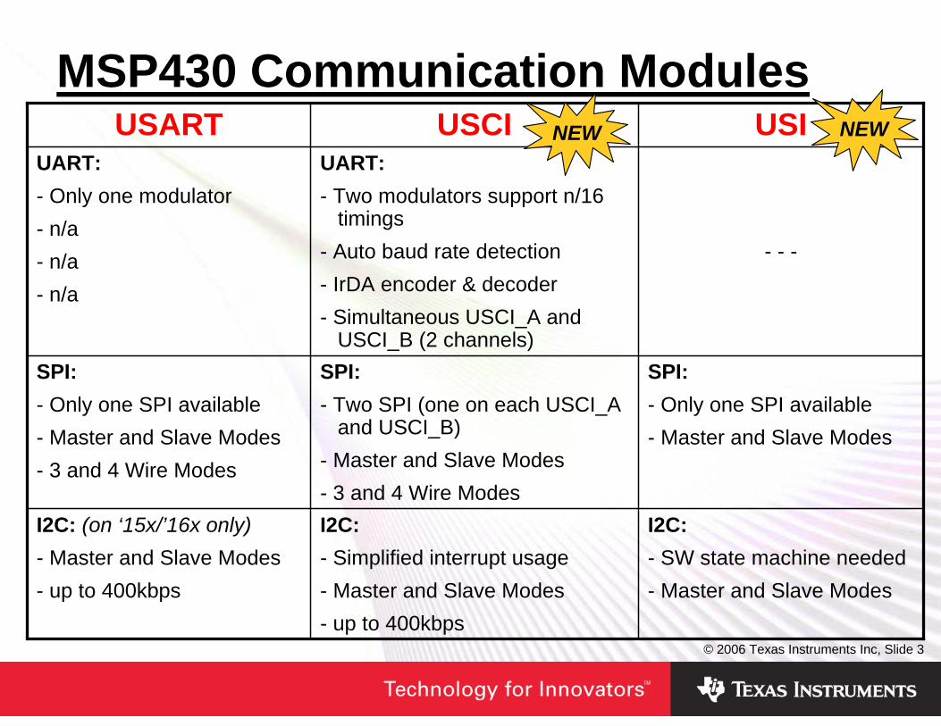
MSP430 Communication Modules
I2C:- SW state machine needed- Master and Slave Modes
I2C:- Simplified interrupt usage- Master and Slave Modes - up to 400kbps
I2C: (on ‘15x/’16x only)- Master and Slave Modes- up to 400kbps
SPI:- Only one SPI available- Master and Slave Modes
SPI:- Two SPI (one on each USCI_A
and USCI_B)- Master and Slave Modes- 3 and 4 Wire Modes
SPI:- Only one SPI available- Master and Slave Modes- 3 and 4 Wire Modes
- - -
UART:- Two modulators support n/16
timings- Auto baud rate detection- IrDA encoder & decoder- Simultaneous USCI_A and
USCI_B (2 channels)
UART:- Only one modulator- n/a- n/a- n/a
USIUSCIUSART NEW NEW

© 2006 Texas Instruments Inc, Slide 4
• USART, USCI, USI Comparison• RS232 Communication • SPI Communication• I2C Communication• Lab Activities
Agenda
© 2006 Texas Instruments Inc, Slide 5
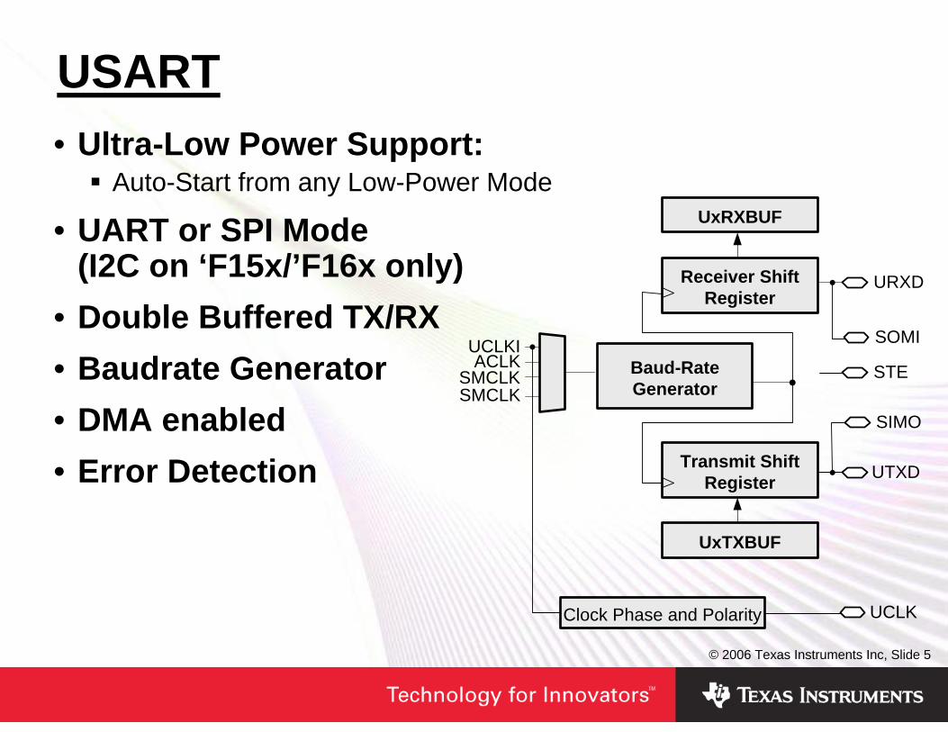
USART• Ultra-Low Power Support:
Auto-Start from any Low-Power Mode
• UART or SPI Mode(I2C on ‘F15x/’F16x only)
• Double Buffered TX/RX• Baudrate Generator• DMA enabled• Error Detection
UxRXBUF
URXD
SMCLK
UCLKIACLK
SMCLK
Receiver Shift Register
Baud-Rate Generator
Transmit Shift Register
UxTXBUF
Clock Phase and Polarity UCLK
UTXD
SOMI
SIMO
STE
© 2006 Texas Instruments Inc, Slide 6
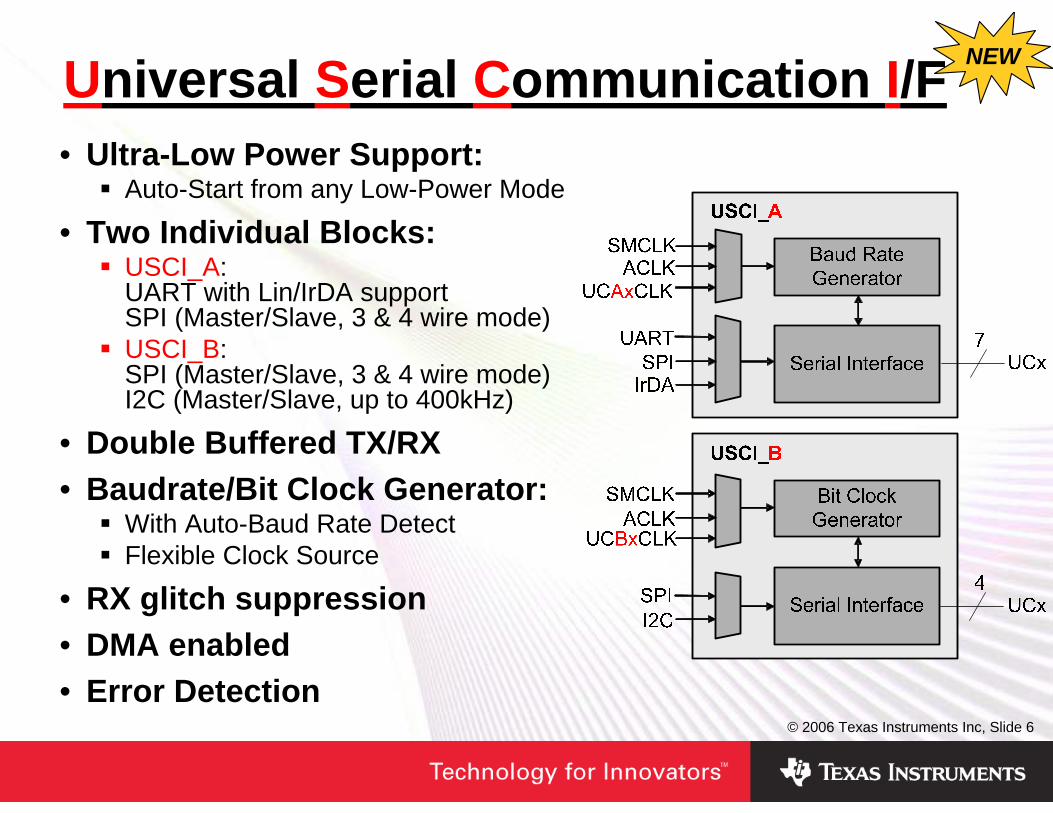
Universal Serial Communication I/F• Ultra-Low Power Support:
Auto-Start from any Low-Power Mode
• Two Individual Blocks:USCI_A: UART with Lin/IrDA supportSPI (Master/Slave, 3 & 4 wire mode) USCI_B: SPI (Master/Slave, 3 & 4 wire mode) I2C (Master/Slave, up to 400kHz)
• Double Buffered TX/RX• Baudrate/Bit Clock Generator:
With Auto-Baud Rate DetectFlexible Clock Source
• RX glitch suppression• DMA enabled• Error Detection
NEW

© 2006 Texas Instruments Inc, Slide 7
• Example: 9600 Baud using 32.768kHz clock source
RS232 Software Solution
Interrupt after x counts
32768Hz
Timer
TXDStart D0 D1 D2 D3 D4 D5 D6 D7 Parity Stop
__interrupt void Timer_ISR(){ if (Data & 0x01) // check data bit 0
SetOutput(); // bit0=1 → P1.0=1else
ResetOutput();// bit0=0 → P1.0=0Data = Data >> 1; // next bit
}
__interrupt void Timer_ISR(){ if (Data & 0x01) // check data bit 0
SetOutput(); // bit0=1 → P1.0=1else
ResetOutput();// bit0=0 → P1.0=0Data = Data >> 1; // next bit
}
Cumulative Error
9600 Baud ⇒ Bit Time = 104.17us ↔ 3x 32768Hz clocks = 91.55us4x 32768Hz clocks = 122.07us
Interrupts after 4 counts:

© 2006 Texas Instruments Inc, Slide 8
Reducing Cumulative Error
9600 Baud ⇒ Bit Time = 104.17us ↔ 3x 32768Hz clocks = 91.55us4x 32768Hz clocks = 122.07us
TXDStart D0 D1 D2 D3 D4 D5 D6 D7 Parity Stop
3 4 3 4 3 3 4 3 3 4 3Redefine bit time
at each interrupt →
• Modulation reduces Cumulative Error:
© 2006 Texas Instruments Inc, Slide 9
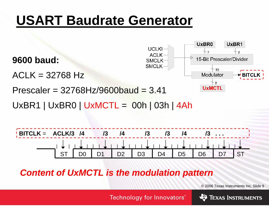
USART Baudrate Generator
9600 baud:ACLK = 32768 Hz
Prescaler = 32768Hz/9600baud = 3.41
UxBR1 | UxBR0 | UxMCTL = 00h | 03h | 4Ah
D0 D1 D2 D3 D4 D5 D6 D7ST ST
BITCLK = ACLK/3 /4 /3 /4 /3 /3 /4 /3 . . .
Content of UxMCTL is the modulation pattern

© 2006 Texas Instruments Inc, Slide 10
USCI Baudrate Generator
Prescaler/Divider
UCAxBR0
1st Modulator BITCLK16
UCAxBR188
UCBRSx3
UC0CLKACLK
SMCLKSMCLK
LSB
/16
2nd Modulator BITCLK
UCBRFx4
NEW
• Oversampling Baud Rate Generation• Two Modulators (UCBRSx and UCBRFx select modulation pattern)
• RX sampled using BITCLK16

© 2006 Texas Instruments Inc, Slide 11
USART Initialization SequenceRecommended USART initialization/re-configuration process as shown in the MSP430 User’s Guide:
Please compare recommendations for USART Module in the MSP430 User’s Guides.

© 2006 Texas Instruments Inc, Slide 12
USCI Initialization SequenceRecommended USCI initialization/re-configuration process as shown in the MSP430 User’s Guide:
Please compare recommendations for USCI Module in the MSP430 User’s Guides.

© 2006 Texas Instruments Inc, Slide 13
• USART, USCI, USI Comparison• RS232 Communication • SPI Communication• I2C Communication• Lab Activities
Agenda
© 2006 Texas Instruments Inc, Slide 14
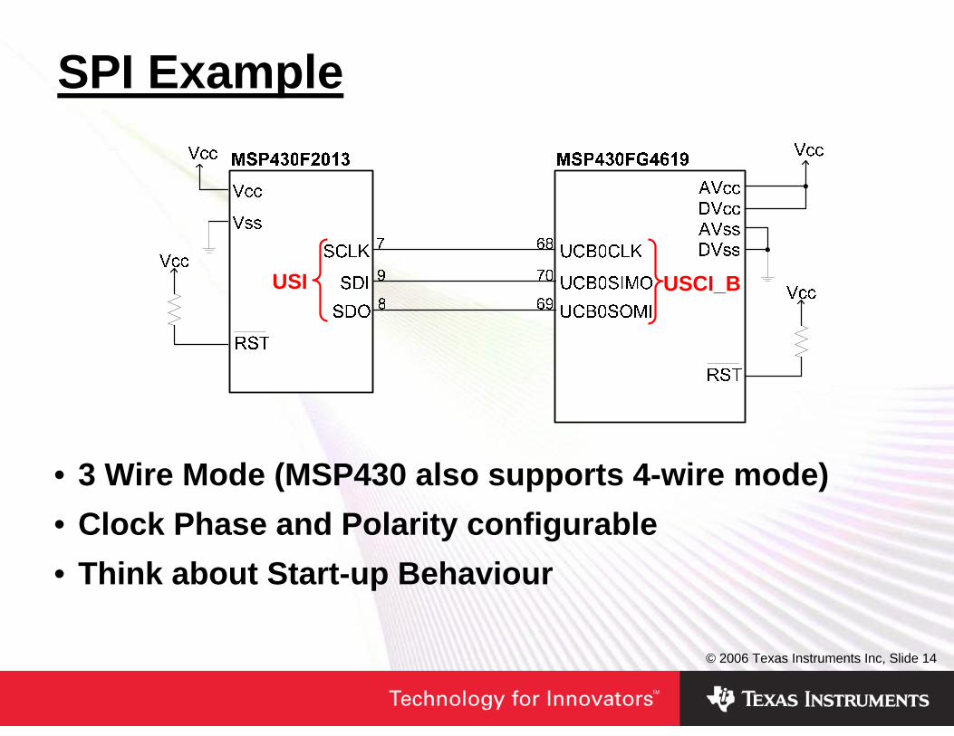
• 3 Wire Mode (MSP430 also supports 4-wire mode)• Clock Phase and Polarity configurable• Think about Start-up Behaviour
SPI Example
USCI_BUSI

© 2006 Texas Instruments Inc, Slide 15
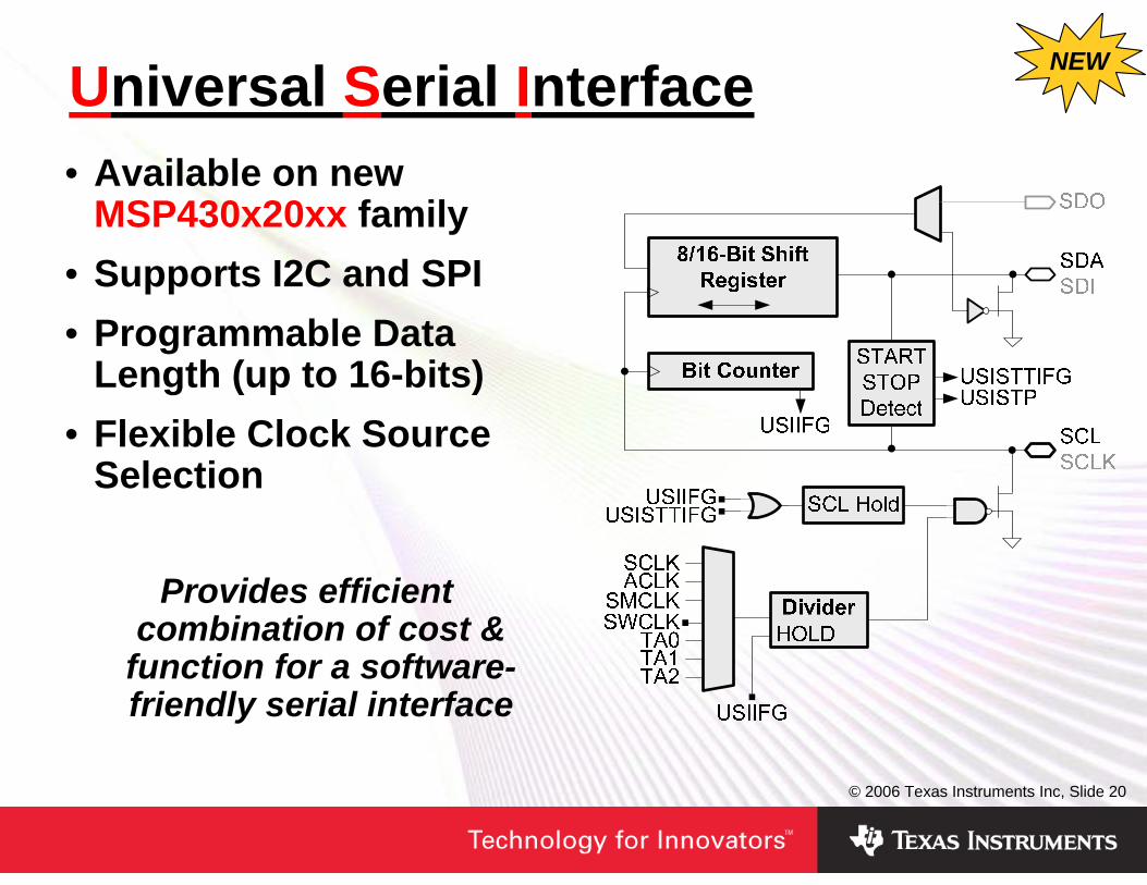
Universal Serial Interface• Available on new
MSP430x20xx family• Supports I2C and SPI• Programmable Data
Length (up to 16-bits)• Flexible Clock Source
Selection
Provides efficient combination of cost &
function for a software-friendly serial interface
NEW
© 2006 Texas Instruments Inc, Slide 16
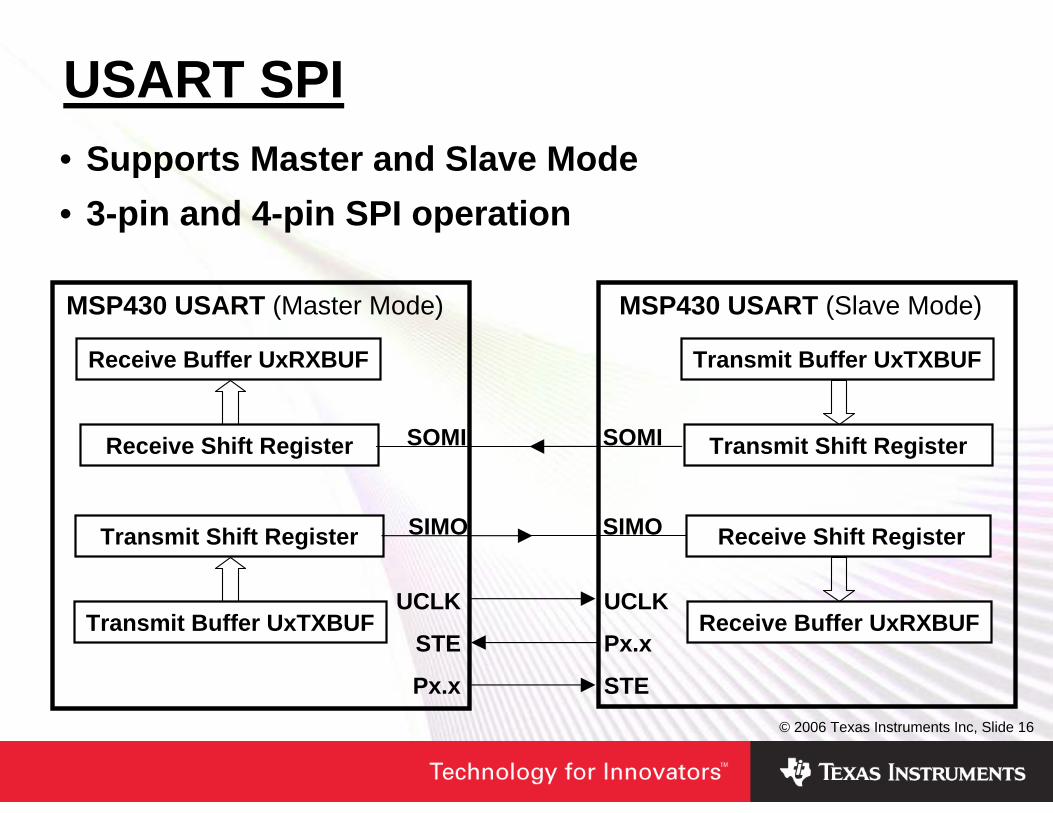
USART SPI• Supports Master and Slave Mode • 3-pin and 4-pin SPI operation
Receive Buffer UxRXBUF
Receive Shift Register
Transmit Shift Register
Transmit Buffer UxTXBUF
MSP430 USART (Master Mode)
Transmit Buffer UxTXBUF
Transmit Shift Register
Receive Shift Register
Receive Buffer UxRXBUF
MSP430 USART (Slave Mode)
UCLK
STE
Px.x
UCLK
Px.x
STE
SIMO
SOMI
SIMO
SOMI

© 2006 Texas Instruments Inc, Slide 17
USCI: SPI Mode• Take care about Clock
Polarity and Phase settings• USCI_A and USCI_B share
TX and RX vector• Software check detects
correct ISR handle:
Receive Shift Regisert
Transmit Shift Register
Receive Buffer
Transmit Buffer
Master Bit Clock Generator (Prescaler,
Clock Polarity and Phase)
BRCLK
SOMI
SIMO
CLK
Slave
Slave
USCI SPI Block Diagram:

© 2006 Texas Instruments Inc, Slide 18
• USART, USCI, USI Comparison• RS232 Communication • SPI Communication• I2C Communication• Lab Activities
Agenda
© 2006 Texas Instruments Inc, Slide 19
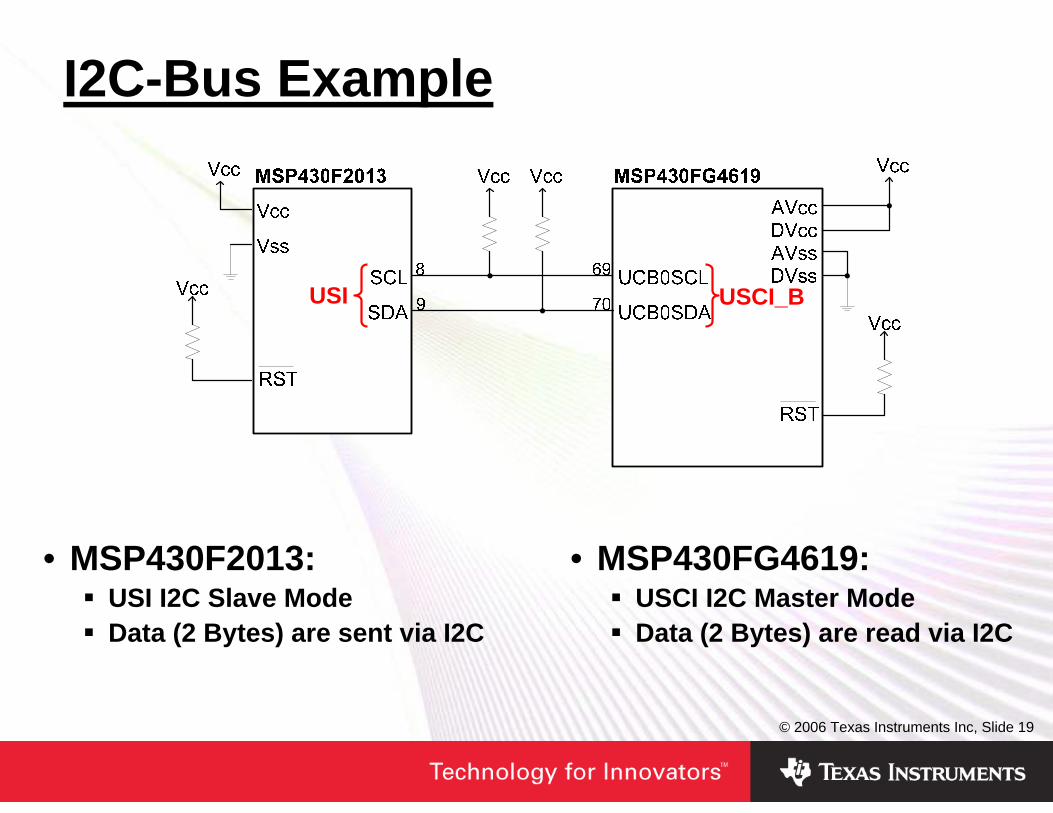
I2C-Bus Example
USCI_BUSI
• MSP430FG4619: USCI I2C Master ModeData (2 Bytes) are read via I2C
• MSP430F2013: USI I2C Slave ModeData (2 Bytes) are sent via I2C
© 2006 Texas Instruments Inc, Slide 20
Universal Serial Interface• Available on new
MSP430x20xx family• Supports I2C and SPI• Programmable Data
Length (up to 16-bits)• Flexible Clock Source
Selection
Provides efficient combination of cost &
function for a software-friendly serial interface
NEW

© 2006 Texas Instruments Inc, Slide 21
USI: I2C Slave Transmitter
Slave Address + R/W bit
Start Condition
SlaveACKN Send DATA
MasterACKN
Stop Condition
1 2 3 4 5
Software State Machine:
IDLE
Receive Address
Process Address and send (N)ACK
Send Data
Receive (N)Ack
Slave Addr. ok
Slave Addr. does not match
Process Data Ack/NAck
1
2
3
4
56
6
I2C Protocol:

© 2006 Texas Instruments Inc, Slide 22
USCI: I2C Communication• Compliance to I2C
Specification V2.1:7-bit/10-bit addressingGeneral callStart/Restart/StopMulti-master transmitter/receiver modeSlave receiver/transmitter modeStandard mode (100kbps)and fast mode (400kbps)support
• Flexible Bit ClockGenerator
• Designed for Low Power
Own Address
UCxSDA
UCxSCL
SMCLK
UC1CLKACLK
SMCLK
Bit Clock Generator
(Prescaler/Divider)
Receive Shift Register
Receive Buffer
UCMST
Transmit Buffer
Transmit Shift Register
Slave Address
I2C State Machine

© 2006 Texas Instruments Inc, Slide 23
• USART, USCI, USI Comparison• RS232 Communication • SPI Communication• I2C Communication• Lab Activities
Agenda

© 2006 Texas Instruments Inc, Slide 24
LAB 1: Instructions• Start IAR Embedded Workbench and create a new Project• Add the file
“msp430xG46x_uscia0_uart_01_115k_modified.c”to the project
• Configure the project options (PROJECT → OPTIONS)• Download the code and start the code• Check RS232 communication between PC and your ATC
board(The demo code will echo back received characters)
• You may change the baud rate by modifying the marked code lines on the following slide (more information about these control registers can be found on slide 26)
© 2006 Texas Instruments Inc, Slide 25
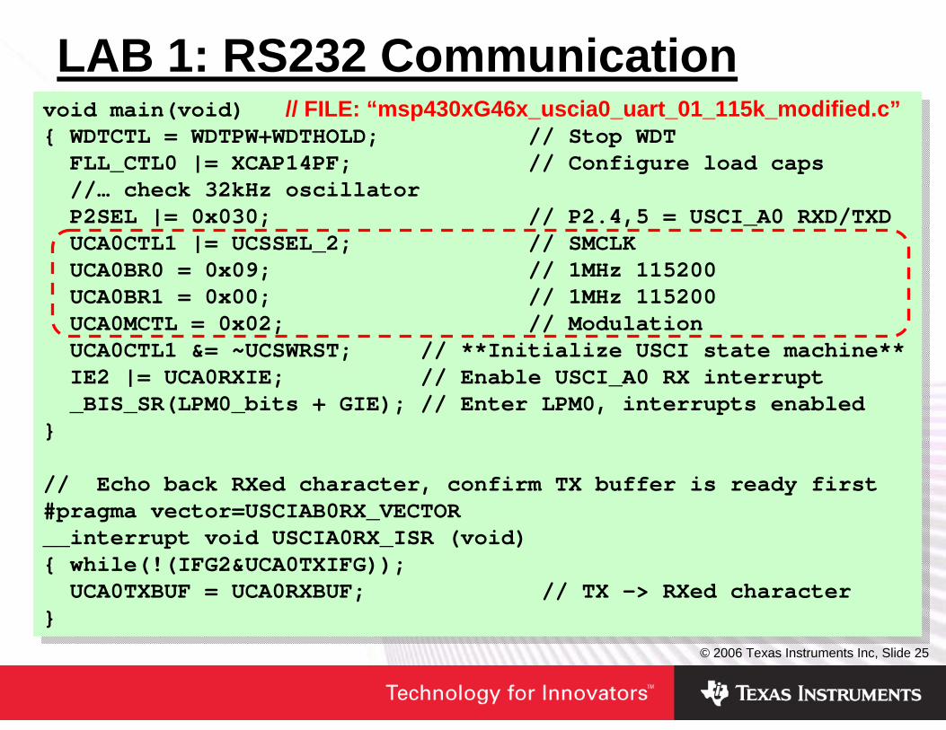
LAB 1: RS232 Communicationvoid main(void) // FILE: “msp430xG46x_uscia0_uart_01_115k_modified.c”{ WDTCTL = WDTPW+WDTHOLD; // Stop WDT
FLL_CTL0 |= XCAP14PF; // Configure load caps//… check 32kHz oscillatorP2SEL |= 0x030; // P2.4,5 = USCI_A0 RXD/TXDUCA0CTL1 |= UCSSEL_2; // SMCLKUCA0BR0 = 0x09; // 1MHz 115200UCA0BR1 = 0x00; // 1MHz 115200UCA0MCTL = 0x02; // ModulationUCA0CTL1 &= ~UCSWRST; // **Initialize USCI state machine**IE2 |= UCA0RXIE; // Enable USCI_A0 RX interrupt_BIS_SR(LPM0_bits + GIE); // Enter LPM0, interrupts enabled
}
// Echo back RXed character, confirm TX buffer is ready first#pragma vector=USCIAB0RX_VECTOR__interrupt void USCIA0RX_ISR (void){ while(!(IFG2&UCA0TXIFG));
UCA0TXBUF = UCA0RXBUF; // TX -> RXed character}
void main(void) // FILE: “msp430xG46x_uscia0_uart_01_115k_modified.c”{ WDTCTL = WDTPW+WDTHOLD; // Stop WDT
FLL_CTL0 |= XCAP14PF; // Configure load caps//… check 32kHz oscillatorP2SEL |= 0x030; // P2.4,5 = USCI_A0 RXD/TXDUCA0CTL1 |= UCSSEL_2; // SMCLKUCA0BR0 = 0x09; // 1MHz 115200UCA0BR1 = 0x00; // 1MHz 115200UCA0MCTL = 0x02; // ModulationUCA0CTL1 &= ~UCSWRST; // **Initialize USCI state machine**IE2 |= UCA0RXIE; // Enable USCI_A0 RX interrupt_BIS_SR(LPM0_bits + GIE); // Enter LPM0, interrupts enabled
}
// Echo back RXed character, confirm TX buffer is ready first#pragma vector=USCIAB0RX_VECTOR__interrupt void USCIA0RX_ISR (void){ while(!(IFG2&UCA0TXIFG));
UCA0TXBUF = UCA0RXBUF; // TX -> RXed character}

© 2006 Texas Instruments Inc, Slide 26
LAB 1: Modify BaudrateMSP430x4xx User’s Guide/USCI Module Description:
UCBRx: UCAxBR0UCAxBR1
UCAxMCTL: UCBRSx UCOS16UCBRFx
UCA0CTL1|= UCSSEL_2;
UCA0CTL1|= UCSSEL_1;

© 2006 Texas Instruments Inc, Slide 27
LAB 2: SPI with USI and USCI1. MSP430F2013:
Download code “msp430x20x3_usi_03_modified.c”
2. MSP430FG4619:Download code “msp430xG46x_uscib0_spi_01_modified.c”Check Jumper on connector H1 (3-4, 7-8)Connect RS232 (115kBaud, 8bit, no parity)Press push-button S1 to read sequence via SPI and show it on PC
© 2006 Texas Instruments Inc, Slide 28
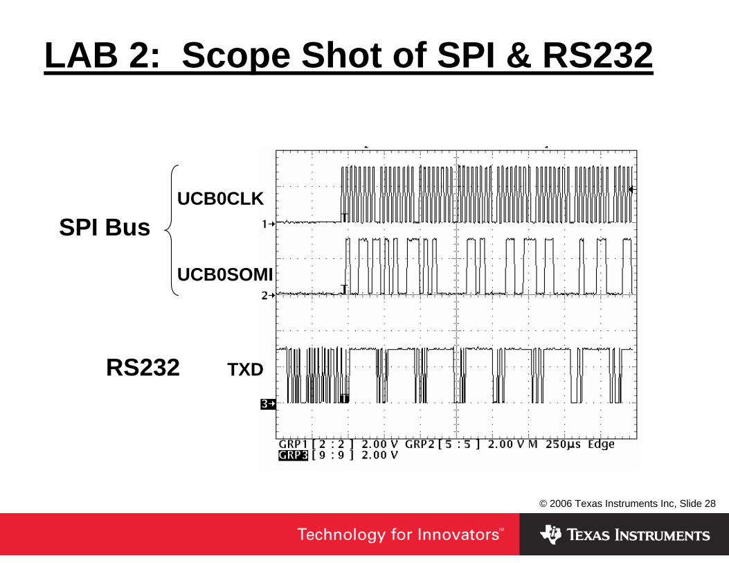
LAB 2: Scope Shot of SPI & RS232
UCB0CLKSPI Bus
UCB0SOMI
RS232 TXD
© 2006 Texas Instruments Inc, Slide 29
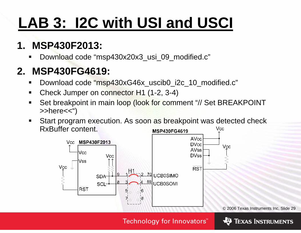
LAB 3: I2C with USI and USCI1. MSP430F2013:
Download code “msp430x20x3_usi_09_modified.c”
2. MSP430FG4619:Download code “msp430xG46x_uscib0_i2c_10_modified.c”Check Jumper on connector H1 (1-2, 3-4)Set breakpoint in main loop (look for comment “// Set BREAKPOINT >>here<<“)Start program execution. As soon as breakpoint was detected check RxBuffer content.
© 2006 Texas Instruments Inc, Slide 30
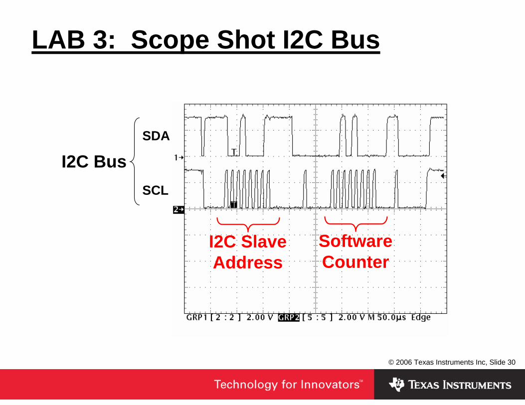
LAB 3: Scope Shot I2C Bus
SDA
I2C BusSCL
Software Counter
I2C Slave Address

© 2006 Texas Instruments Inc, Slide 31
Summary• There are different solutions! MSP430’s peripheral
communication modules helps you to reduce CPU loading
• Be aware about the initialization sequence of USART and USCI modules (follow the recommendations of the User’s Guides)
• Detailed module descriptions can be found in the MSP430 User’s Guides
• Code examples are available on the MSP430 homepage (www.ti.com/msp430)
x00geoff
Text Box
SLAP117

IMPORTANT NOTICE
Texas Instruments Incorporated and its subsidiaries (TI) reserve the right to make corrections, modifications, enhancements,improvements, and other changes to its products and services at any time and to discontinue any product or service without notice.Customers should obtain the latest relevant information before placing orders and should verify that such information is current andcomplete. All products are sold subject to TI’s terms and conditions of sale supplied at the time of order acknowledgment.
TI warrants performance of its hardware products to the specifications applicable at the time of sale in accordance with TI’sstandard warranty. Testing and other quality control techniques are used to the extent TI deems necessary to support thiswarranty. Except where mandated by government requirements, testing of all parameters of each product is not necessarilyperformed.
TI assumes no liability for applications assistance or customer product design. Customers are responsible for their products andapplications using TI components. To minimize the risks associated with customer products and applications, customers shouldprovide adequate design and operating safeguards.
TI does not warrant or represent that any license, either express or implied, is granted under any TI patent right, copyright, maskwork right, or other TI intellectual property right relating to any combination, machine, or process in which TI products or servicesare used. Information published by TI regarding third-party products or services does not constitute a license from TI to use suchproducts or services or a warranty or endorsement thereof. Use of such information may require a license from a third party underthe patents or other intellectual property of the third party, or a license from TI under the patents or other intellectual property of TI.
Reproduction of information in TI data books or data sheets is permissible only if reproduction is without alteration and isaccompanied by all associated warranties, conditions, limitations, and notices. Reproduction of this information with alteration is anunfair and deceptive business practice. TI is not responsible or liable for such altered documentation.
Resale of TI products or services with statements different from or beyond the parameters stated by TI for that product or servicevoids all express and any implied warranties for the associated TI product or service and is an unfair and deceptive businesspractice. TI is not responsible or liable for any such statements.
TI products are not authorized for use in safety-critical applications (such as life support) where a failure of the TI product wouldreasonably be expected to cause severe personal injury or death, unless officers of the parties have executed an agreementspecifically governing such use. Buyers represent that they have all necessary expertise in the safety and regulatory ramificationsof their applications, and acknowledge and agree that they are solely responsible for all legal, regulatory and safety-relatedrequirements concerning their products and any use of TI products in such safety-critical applications, notwithstanding anyapplications-related information or support that may be provided by TI. Further, Buyers must fully indemnify TI and itsrepresentatives against any damages arising out of the use of TI products in such safety-critical applications.
TI products are neither designed nor intended for use in military/aerospace applications or environments unless the TI products arespecifically designated by TI as military-grade or "enhanced plastic." Only products designated by TI as military-grade meet militaryspecifications. Buyers acknowledge and agree that any such use of TI products which TI has not designated as military-grade issolely at the Buyer's risk, and that they are solely responsible for compliance with all legal and regulatory requirements inconnection with such use.
TI products are neither designed nor intended for use in automotive applications or environments unless the specific TI productsare designated by TI as compliant with ISO/TS 16949 requirements. Buyers acknowledge and agree that, if they use anynon-designated products in automotive applications, TI will not be responsible for any failure to meet such requirements.
Following are URLs where you can obtain information on other Texas Instruments products and application solutions:
Products Applications
Amplifiers amplifier.ti.com Audio www.ti.com/audio
Data Converters dataconverter.ti.com Automotive www.ti.com/automotive
DSP dsp.ti.com Broadband www.ti.com/broadband
Interface interface.ti.com Digital Control www.ti.com/digitalcontrol
Logic logic.ti.com Military www.ti.com/military
Power Mgmt power.ti.com Optical Networking www.ti.com/opticalnetwork
Microcontrollers microcontroller.ti.com Security www.ti.com/security
RFID www.ti-rfid.com Telephony www.ti.com/telephony
Low Power www.ti.com/lpw Video & Imaging www.ti.com/videoWireless
Wireless www.ti.com/wireless
Mailing Address: Texas Instruments, Post Office Box 655303, Dallas, Texas 75265Copyright © 2007, Texas Instruments Incorporated