Introduction to Mobile Telephone Systems
92
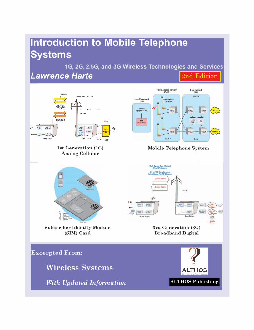
Introduction to Mobile Telephone Systems 1G, 2G, 2.5G, and 3G Wireless Technologies and Services Lawrence Harte Excerpted From: Wireless Systems With Updated Information ALTHOS Publishing 1st Generation (1G) Analog Cellular Mobile Telephone System 3rd Generation (3G) Broadband Digital Subscriber Identity Module (SIM) Card 2nd Edition
Transcript of Introduction to Mobile Telephone Systems
Introduction to Mobile TelephoneSystems
1G, 2G, 2.5G, and 3G Wireless Technologies and ServicesLawrence Harte
Excerpted From:
Wireless Systems
With Updated Information ALTHOS Publishing
1st Generation (1G)Analog Cellular
Mobile Telephone System
3rd Generation (3G)Broadband Digital
Subscriber Identity Module(SIM) Card
2nd Edition
ALTHOS Publishing
Copyright © 2006 by the ALTHOS Publishing Inc. All rights reserved. Produced in theUnited States of America. Except as permitted under the United States Copyright Act of1976, no part of this publication may be reproduced or distributed in any form or by anymeans, or stored in a database or retrieval system, without prior written permission of thepublisher.
ISBN: 1-932813-93-4
All trademarks are trademarks of their respective owners. We use names to assist in theexplanation or description of information to the benefit of the trademark owner and ALTHOSpublishing does not have intentions for the infringement of any trademark.
ALTHOS electronic books (ebooks) and images are available for use in educational, promo-tional materials, training programs, and other uses. For more information about usingALTHOS ebooks and images, please contact us at [email protected] or (919) 557-2260
Terms of Use
This is a copyrighted work and ALTHOS Publishing Inc. (ALTHOS) and its licensors reserveall rights in and to the work. This work may be sued for your own noncommercial and per-sonal use; any other use of the work is strictly prohibited. Use of this work is subject to theCopyright Act of 1976, and in addition, this work is subject to these additional terms, exceptas permitted under the and the right to store and retrieve one copy of the work, you may notdisassemble, decompile, copy or reproduce, reverse engineer, alter or modify, develop deriva-tive works based upon these contents, transfer, distribute, publish, sell, or sublicense thiswork or any part of it without ALTHOS prior consent. Your right to use the work may be ter-minated if you fail to comply with these terms.
ALTHOS AND ITS LICENSORS MAKE NO WARRANTIES OR GUARANTEES OF THEACCURACY, SUFFICIENCY OR COMPLETENESS OF THIS WORK NOR THE RESULTSTHAT MAY BE OBTAINED FROM THE USE OF MATERIALS CONTAINED WITHINTHE WORK. APDG DISCLAIMS ANY WARRANTY, EXPRESS OR IMPLIED, INCLUDINGBUT NOT LIMITED TO IMPLIED WARRANTIES OF MERCHANTABILITY OR FITNESSFOR A PARTICULAR PURPOSE.
ALTHOS and its licensors does warrant and guarantee that the information contained with-in shall be usable by the purchaser of this material and the limitation of liability shall be lim-ited to the replacement of the media or refund of the purchase price of the work.
ALTHOS and its licensors shall not be liable to you or anyone else for any inaccuracy, erroror omission, regardless of cause, in the work or for any damages resulting there from.ALTHOS and/or its licensors shall not be liable for any damages including incidental, indi-rect, punitive, special, consequential or similar types of damages that may result from theattempted use or operation of the work.
-ii-
Copyright ©, 2006, ALTHOS, Inc
-iii-
Copyright ©, 2006, ALTHOS, Inc
About the Authors
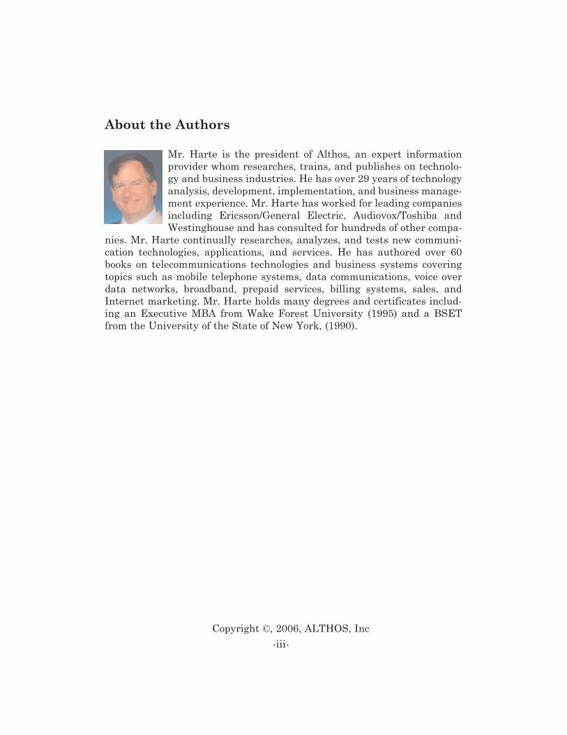
Mr. Harte is the president of Althos, an expert informationprovider whom researches, trains, and publishes on technolo-gy and business industries. He has over 29 years of technologyanalysis, development, implementation, and business manage-ment experience. Mr. Harte has worked for leading companiesincluding Ericsson/General Electric, Audiovox/Toshiba andWestinghouse and has consulted for hundreds of other compa-
nies. Mr. Harte continually researches, analyzes, and tests new communi-cation technologies, applications, and services. He has authored over 60books on telecommunications technologies and business systems coveringtopics such as mobile telephone systems, data communications, voice overdata networks, broadband, prepaid services, billing systems, sales, andInternet marketing. Mr. Harte holds many degrees and certificates includ-ing an Executive MBA from Wake Forest University (1995) and a BSETfrom the University of the State of New York, (1990).

-iv-
Copyright ©, 2006, ALTHOS, Inc
-v-
Copyright ©, 2006, ALTHOS, Inc
Table of Contents
MOBILE TECHNOLOGIES . . . . . . . . . . . . . . . . . . . . . . . . . . . . . 2
CELLULAR FREQUENCY REUSE . . . . . . . . . . . . . . . . . . . . . . . . . . . . . 3HANDOVER . . . . . . . . . . . . . . . . . . . . . . . . . . . . . . . . . . . . . . . . . . . 5SPEECH COMPRESSION . . . . . . . . . . . . . . . . . . . . . . . . . . . . . . . . . . . 7MODULATION TYPES . . . . . . . . . . . . . . . . . . . . . . . . . . . . . . . . . . . . . 8ACCESS MULTIPLEXING . . . . . . . . . . . . . . . . . . . . . . . . . . . . . . . . . . 9
Frequency Division Multiple Access (FDMA) . . . . . . . . . . . . . .10Time Division Multiple Access (TDMA) . . . . . . . . . . . . . . . . . .11Code Division Multiple Access (CDMA) . . . . . . . . . . . . . . . . . .12Spatial Division Multiple Access (SDMA) . . . . . . . . . . . . . . . .13
PACKET DATA . . . . . . . . . . . . . . . . . . . . . . . . . . . . . . . . . . . . . . . . 14
MOBILE DEVICES . . . . . . . . . . . . . . . . . . . . . . . . . . . . . . . . . . . 15
SUBSCRIBER IDENTITY MODULE (SIM) . . . . . . . . . . . . . . . . . . . . . . 15PCMCIA AIR CARDS . . . . . . . . . . . . . . . . . . . . . . . . . . . . . . . . . . . 17EMBEDDED RADIO MODULES . . . . . . . . . . . . . . . . . . . . . . . . . . . . . 17MOBILE TELEPHONES . . . . . . . . . . . . . . . . . . . . . . . . . . . . . . . . . . . 17EXTERNAL RADIO MODEMS . . . . . . . . . . . . . . . . . . . . . . . . . . . . . . . 17
MOBILE SYSTEMS . . . . . . . . . . . . . . . . . . . . . . . . . . . . . . . . . . 19
BASE STATIONS . . . . . . . . . . . . . . . . . . . . . . . . . . . . . . . . . . . . . . . 20RADIO ANTENNA TOWERS . . . . . . . . . . . . . . . . . . . . . . . . . . . . . . . . 21COMMUNICATION LINKS . . . . . . . . . . . . . . . . . . . . . . . . . . . . . . . . . 21MOBILE SWITCHING CENTER (MSC) . . . . . . . . . . . . . . . . . . . . . . . . 22AUTHENTICATION, AUTHORIZATION, AND ACCOUNTING (AAA) . . . . . 22INTERWORKING FUNCTION (IWF) . . . . . . . . . . . . . . . . . . . . . . . . . . 22MESSAGE CENTER (MC) . . . . . . . . . . . . . . . . . . . . . . . . . . . . . . . . . 23SERVING GENERAL PACKET RADIO SERVICE SUPPORT NODE (SGSN)
23
-vi-
Copyright ©, 2006, ALTHOS, Inc
GATEWAY GPRS SUPPORT NODE (GGSN) . . . . . . . . . . . . . . . . . . . 23BASE STATION CONTROLLER (BSC) . . . . . . . . . . . . . . . . . . . . . . . . . 23VOICE MESSAGE SYSTEM (VMS) . . . . . . . . . . . . . . . . . . . . . . . . . . . 24PUBLIC SWITCHED TELEPHONE NETWORK (PSTN) . . . . . . . . . . . . . 24PUBLIC PACKET DATA NETWORK (PPDN) . . . . . . . . . . . . . . . . . . . . 24NETWORK DATABASES . . . . . . . . . . . . . . . . . . . . . . . . . . . . . . . . . . 24
Home Location Register (HLR) . . . . . . . . . . . . . . . . . . . . . . . . .25Visitor Location Register (VLR) . . . . . . . . . . . . . . . . . . . . . . . .25Equipment Identity Register (EIR) . . . . . . . . . . . . . . . . . . . . . .25Billing Center (BC) . . . . . . . . . . . . . . . . . . . . . . . . . . . . . . . . . .26Authentication Centre (AuC) . . . . . . . . . . . . . . . . . . . . . . . . . . .26Number Portability Database (NPDB) . . . . . . . . . . . . . . . . . . .26
IP BACKBONE NETWORK . . . . . . . . . . . . . . . . . . . . . . . . . . . . . . . . 27
MOBILE SYSTEM OPERATION . . . . . . . . . . . . . . . . . . . . . . . 27
INITIALIZATION . . . . . . . . . . . . . . . . . . . . . . . . . . . . . . . . . . . . . . . 29IDLE . . . . . . . . . . . . . . . . . . . . . . . . . . . . . . . . . . . . . . . . . . . . . . . 29ACCESS CONTROL AND INITIAL ASSIGNMENT . . . . . . . . . . . . . . . . . . 30
Authentication . . . . . . . . . . . . . . . . . . . . . . . . . . . . . . . . . . . . .31Paging . . . . . . . . . . . . . . . . . . . . . . . . . . . . . . . . . . . . . . . . . . . .32
CONNECTED MODE . . . . . . . . . . . . . . . . . . . . . . . . . . . . . . . . . . . . . 32PACKET DATA SCHEDULING ALGORITHM . . . . . . . . . . . . . . . . . . . . . 33REGISTRATION . . . . . . . . . . . . . . . . . . . . . . . . . . . . . . . . . . . . . . . . 34
ANALOG SYSTEMS (1ST GENERATION) . . . . . . . . . . . . . . . 34
ADVANCED MOBILE PHONE SERVICE (AMPS) . . . . . . . . . . . . . . . . . 39TOTAL ACCESS COMMUNICATION SYSTEM (TACS) . . . . . . . . . . . . . . 40NORDIC MOBILE TELEPHONE (NMT) . . . . . . . . . . . . . . . . . . . . . . . 41NARROWBAND AMPS (NAMPS) . . . . . . . . . . . . . . . . . . . . . . . . . . . 43JAPANESE MOBILE CELLULAR SYSTEM (MCS) . . . . . . . . . . . . . . . . . 44CNET . . . . . . . . . . . . . . . . . . . . . . . . . . . . . . . . . . . . . . . . . . . . . . 45MATS-E . . . . . . . . . . . . . . . . . . . . . . . . . . . . . . . . . . . . . . . . . . . . 45
DIGITAL CELLULAR SYSTEMS (2ND GENERATION) . . . . 46
GLOBAL SYSTEM FOR MOBILE COMMUNICATION (GSM) . . . . . . . . . . 51NORTH AMERICAN TDMA (IS-136 TDMA) . . . . . . . . . . . . . . . . . . . 52EXTENDED TDMA (E-TDMA)TM . . . . . . . . . . . . . . . . . . . . . . . . . 54INTEGRATED DISPATCH ENHANCED NETWORK (IDEN) . . . . . . . . . . . 56CODE DIVISION MULTIPLE ACCESS (IS-95 CDMA) . . . . . . . . . . . . . 56JAPANESE PERSONAL DIGITAL CELLULAR (PDC) . . . . . . . . . . . . . . . 58
PACKET DIGITAL CELLULAR SYSTEMS (GENERATION 2.5). . . . . . . . . . . . . . . . . . . . . . . . . . . . . . . . . . . . . . . . . . . . . . . . . . . . 59
GENERAL PACKET RADIO SERVICE (GPRS) . . . . . . . . . . . . . . . . . . . 60ENHANCED DATA RATES FOR GLOBAL EVOLUTION (EDGE) . . . . . . . 60CDMA2000™ 1XRTT . . . . . . . . . . . . . . . . . . . . . . . . . . . . . . . . . 61EVOLUTION DATA ONLY (1XEVDO) . . . . . . . . . . . . . . . . . . . . . . . . 61EVOLUTION DATA AND VOICE (1XEVDV) . . . . . . . . . . . . . . . . . . . . 61
WIDEBAND DIGITAL CELLULAR SYSTEMS (3RD GENERATION) . . . . . . . . . . . . . . . . . . . . . . . . . . . . . . . . . . . . 62
WIDEBAND CODE DIVISION MULTIPLE ACCESS (WCDMA) . . . . . . . . 63CODE DIVISION MULTIPLE ACCESS 2000 (CDMA2000) . . . . . . . . . . 64TIME DIVISION SYNCHRONOUS CDMA (TD-SCDMA) . . . . . . . . . . . 64
FOURTH GENERATION (4G) NETWORKS . . . . . . . . . . . . . . 64
MOBILE SERVICES . . . . . . . . . . . . . . . . . . . . . . . . . . . . . . . . . 65
VOICE SERVICES . . . . . . . . . . . . . . . . . . . . . . . . . . . . . . . . . . . . . . 65Circuit Switched Voice . . . . . . . . . . . . . . . . . . . . . . . . . . . . . . .66Push to Talk (PTT) . . . . . . . . . . . . . . . . . . . . . . . . . . . . . . . . . .67
MESSAGING . . . . . . . . . . . . . . . . . . . . . . . . . . . . . . . . . . . . . . . . . . 68DATA SERVICE . . . . . . . . . . . . . . . . . . . . . . . . . . . . . . . . . . . . . . . . 68
Circuit Switched Data . . . . . . . . . . . . . . . . . . . . . . . . . . . . . . .69Packet Switched Data . . . . . . . . . . . . . . . . . . . . . . . . . . . . . . . .69
LOCATION BASED SERVICES (LBS) . . . . . . . . . . . . . . . . . . . . . . . . . 70MULTICAST SERVICES . . . . . . . . . . . . . . . . . . . . . . . . . . . . . . . . . . . 70
-vii-
Copyright ©, 2006, ALTHOS, Inc
QUALITY OF SERVICE (QOS) . . . . . . . . . . . . . . . . . . . . . . . . . . . . . . 70Conversation Class . . . . . . . . . . . . . . . . . . . . . . . . . . . . . . . . . .71Streaming Class . . . . . . . . . . . . . . . . . . . . . . . . . . . . . . . . . . . .71Interactive Class . . . . . . . . . . . . . . . . . . . . . . . . . . . . . . . . . . . .71Background Class . . . . . . . . . . . . . . . . . . . . . . . . . . . . . . . . . . .72
-viii-
Copyright ©, 2006, ALTHOS, Inc
-1-
Copyright ©, 2006, ALTHOS, Inc
Introduction to Mobile TelephoneSystems
Mobile telephone service (MTS) is a type of service where mobile radio tele-phones connect people to the public switched telephone system (PSTN), toother mobile telephones or to other communication systems (such as to theInternet).
Cellular, personal communication service (PCS), and third generation 3Gmobile radio systems are all cellular wireless communication networks thatprovide for voice and data communication throughout a wide geographicarea. Cellular systems divide large geographic areas into small radio areas(cells) that are interconnected with each other. Each cell coverage area hasone or several transmitters and receivers that communicate with mobiletelephones within its area.
Figure 1.1 shows a basic cellular mobile communications system. The cellu-lar system connects mobile radios (called mobile stations) via radio channelsto base stations. Some of the radio channels (or portions of a digital radiochannel) are used for control purposes (setup and disconnection of calls) andsome are used to transfer voice or customer data signals. Each base stationcontains transmitters and receivers that convert the radio signals to electri-cal signals that can be sent to and from the mobile switching center (MSC).The MSC contains communication controllers that adapt signals from basestations into a form that can be connected (switched) between other basestations or to lines that connect to the public telephone network. The switch-ing system is connected to databases that contain active customers (cus-
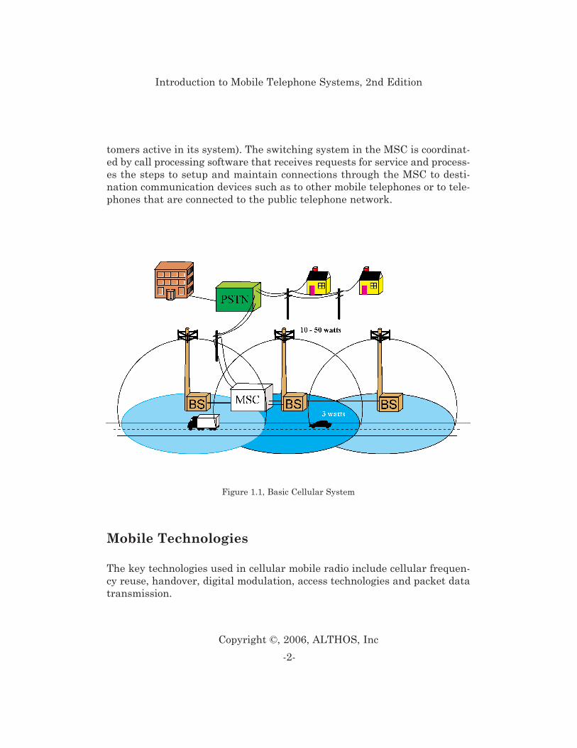
tomers active in its system). The switching system in the MSC is coordinat-ed by call processing software that receives requests for service and process-es the steps to setup and maintain connections through the MSC to desti-nation communication devices such as to other mobile telephones or to tele-phones that are connected to the public telephone network.
Mobile Technologies
The key technologies used in cellular mobile radio include cellular frequen-cy reuse, handover, digital modulation, access technologies and packet datatransmission.
-2-
Copyright ©, 2006, ALTHOS, Inc
Introduction to Mobile Telephone Systems, 2nd Edition
Figure 1.1, Basic Cellular System
Cellular Frequency Reuse
Frequency reuse is the process of using the same radio frequencies on radiotransmitter sites within a geographic area that are separated by sufficientdistance to cause minimal interference with each other. Frequency reuseallows for a dramatic increase in the number of customers that can beserved (capacity) within a geographic area on a limited amount of radiospectrum (limited number of radio channels).
In early mobile radio telephone systems, one high-power transmitter serveda large geographic area with a limited number of radio channels. Becauseeach radio channel requires a certain frequency bandwidth (radio spectrum)and there is a very limited amount of radio spectrum available, this dra-matically limits the number of radio channels that keeps the low servingcapacity of such systems. For example, in 1976, New York City had only 12radio channels to support 545 customers and a two-year long waiting list oftypically 3,700 [1].
To conserve the limited amount of radio spectrum (maximum number ofavailable radio channels), the cellular system concept was developed.Cellular systems allow reuse of the same channel frequencies many timeswithin a geographic coverage area. The technique (called frequency reuse)makes it possible for a system to provide service to more customers (calledsystem capacity) by reusing the channels that are available in a geographicarea. In large systems such as the systems operating in New York City andLos Angeles, radio channel frequencies may be reused over 300 times. Assystems start to become overloaded with many users, to increase capacity,the system can expand by adding more radio channels to the base station orby adding more cell cites with smaller coverage areas.
To minimize interference in this way, cellular system planners position thecell sites that use the same radio channel farthest away from each other.The distances between sites are initially planned by general RF signal prop-agation rules. It is difficult to account for enough propagation factors to pre-cisely position the towers, which usually leads the cell site position andpower levels to be adjusted later.
-3-
Copyright ©, 2006, ALTHOS, Inc
Introduction to Mobile Telephone Systems, 2nd Edition
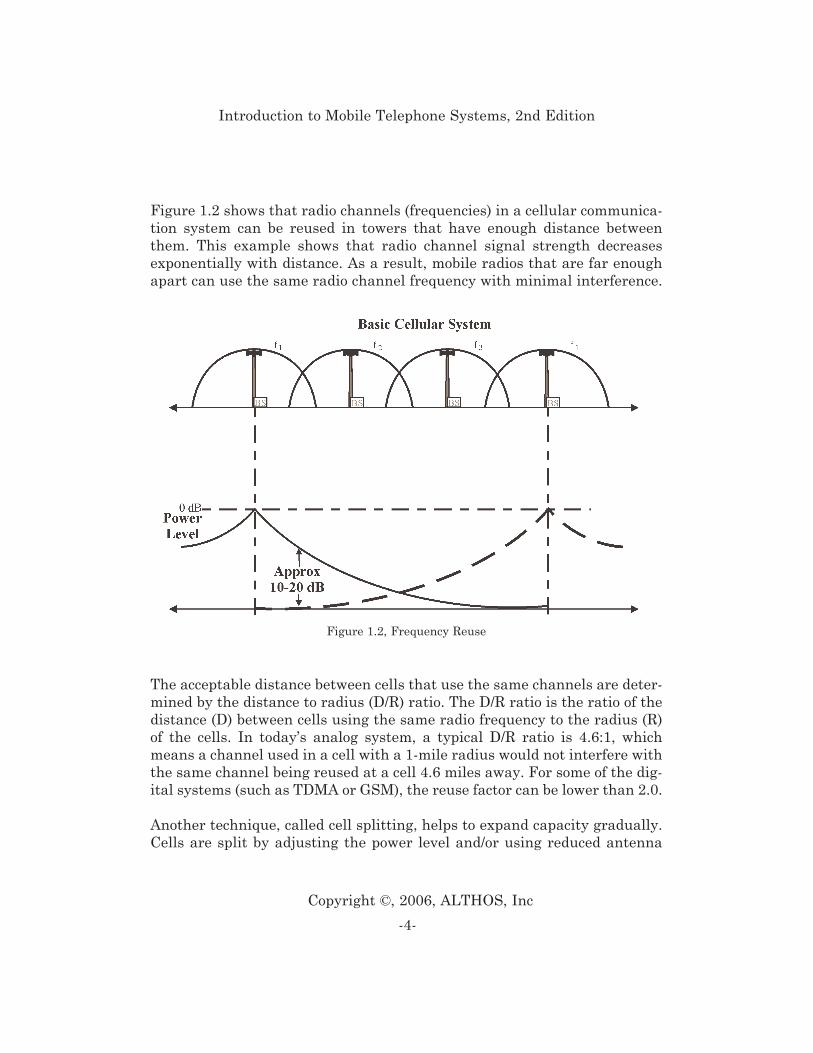
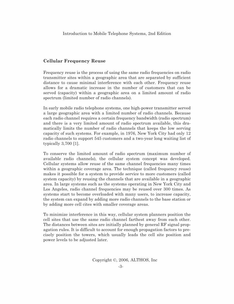
Figure 1.2 shows that radio channels (frequencies) in a cellular communica-tion system can be reused in towers that have enough distance betweenthem. This example shows that radio channel signal strength decreasesexponentially with distance. As a result, mobile radios that are far enoughapart can use the same radio channel frequency with minimal interference.
The acceptable distance between cells that use the same channels are deter-mined by the distance to radius (D/R) ratio. The D/R ratio is the ratio of thedistance (D) between cells using the same radio frequency to the radius (R)of the cells. In today’s analog system, a typical D/R ratio is 4.6:1, whichmeans a channel used in a cell with a 1-mile radius would not interfere withthe same channel being reused at a cell 4.6 miles away. For some of the dig-ital systems (such as TDMA or GSM), the reuse factor can be lower than 2.0.
Another technique, called cell splitting, helps to expand capacity gradually.Cells are split by adjusting the power level and/or using reduced antenna
-4-
Copyright ©, 2006, ALTHOS, Inc
Introduction to Mobile Telephone Systems, 2nd Edition
Figure 1.2, Frequency Reuse
height to cover a reduced area. Reducing a coverage area by changing theRF boundaries of a cell site has the same effect as placing cells farther apart,and allows new cell sites to be added. However, the boundaries of a cell sitevary with the terrain and land conditions, especially with seasonal varia-tions in foliage. Coverage areas can actually increase in fall and winter asthe leaves fall from the trees.
When a cellular system is first established, it can effectively serve only alimited number of callers. When that limit is exceeded, callers experiencesystem busy signals (known as blocking) and their calls cannot be complet-ed. More callers can be served by adding more cells with smaller coverageareas - that is, by cell splitting. The increased number of smaller cells pro-vides more available radio channels in a given area because it allows radiochannels to be reused at closer geographical distances.
When linked together to cover an entire metro area, the radio coverageareas (called cells) form a cellular structure resembling that of a honeycomb.Cellular systems are designed to overlap each cell border with adjacent cellborders to enable a “handover” from one cell to the next. As a customer(called a subscriber) moves through a cellular system, the mobile switchingcenter (MSC) coordinates and transfers calls from one cell to another andmaintains call continuity.
Handover
Handover is a process where a mobile radio operating on a particular chan-nel is reassigned to a new channel. The process is often used to allow sub-scribers to travel throughout the large radio system coverage area byswitching the calls (handover) from cell-to-cell (and different channels) withbetter coverage for that particular area when poor quality conversation isdetected.
Handover (also called handoff) is necessary for two reasons. First, where themobile unit moves out of range of one cell site and is within range of anoth-er cell site. Second, a handover may be required when the mobile hasrequested the services of a type of cellular channel that different capabili-
-5-
Copyright ©, 2006, ALTHOS, Inc
Introduction to Mobile Telephone Systems, 2nd Edition
ties (e.g. packet data). This might mean assignment from a digital channelto an analog channel or assignment from a wide digital channel to a packetdata channel.
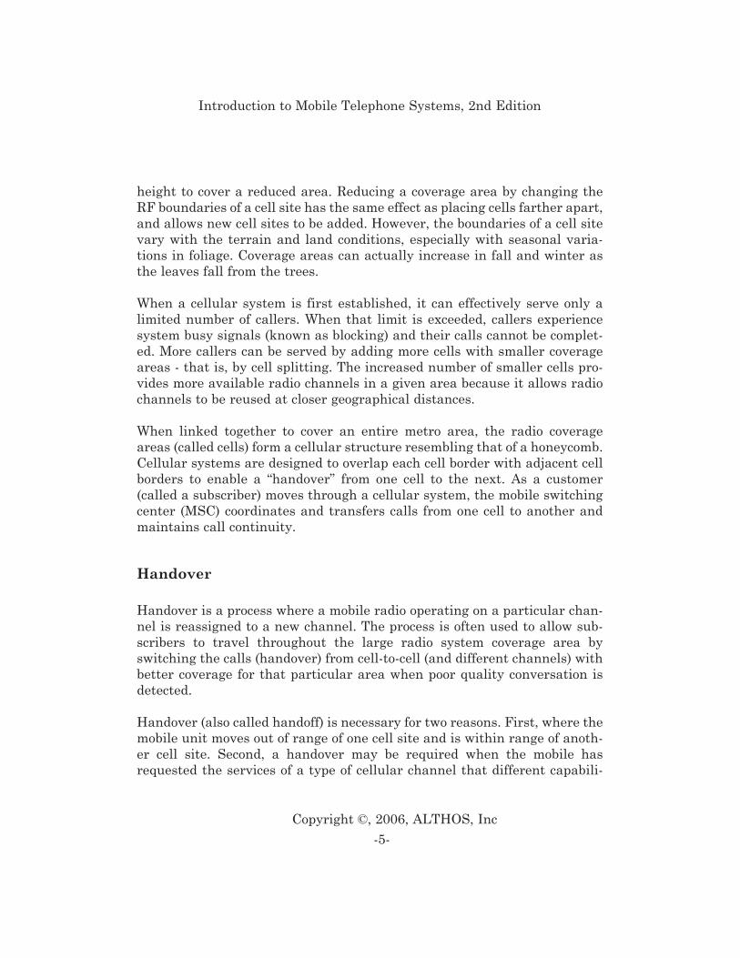
Figure 1.3 shows the basic handoff process that occurs in a mobile telephonesystem. In this example, the system has determined that the radio signalstrength of mobile telephone has fallen below a predefined level. When thisoccurs, the serving base station sends a control message to the system indi-cating that the signal quality of the mobile’s radio signal is declining and ahandover may be necessary. The system determines that an adjacent cellsite is a candidate for the handoff and it sends command messages to theadjacent cell site to prepare to receive a new connection. Messages areexchanged between the base stations and the mobile device that informs itto change to a new channel and the MSC switches the audio path to the newcell site when necessary.
-6-
Copyright ©, 2006, ALTHOS, Inc
Introduction to Mobile Telephone Systems, 2nd Edition
Figure 1.3, Handover Operation
Speech Compression
Speech compression is a technique for converting or encoding audio (sound)information so that a smaller amount of information elements or reducedbandwidth is required to represent, store or transfer audio signals.
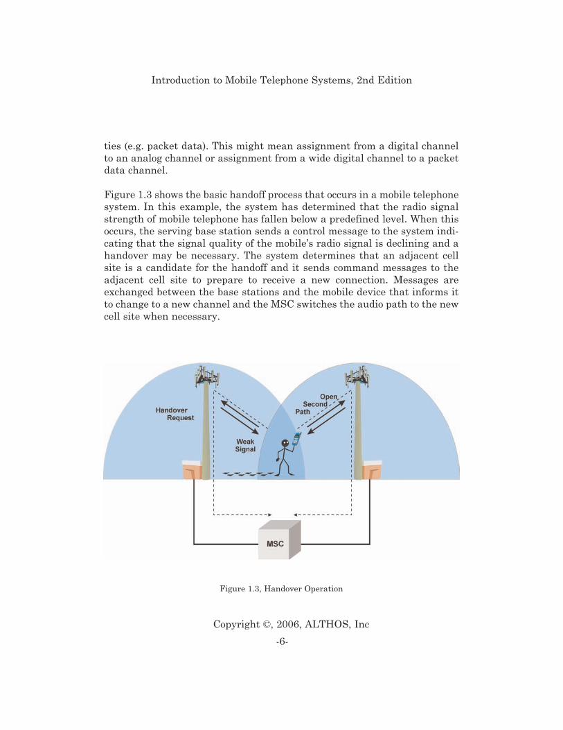
Figure 1.4 shows the basic digital speech compression process. The first stepis to periodically sample the analog voice signal (5 - 20 msec) into pulse codemodulated (PCM) digital form (usually 64 kbps). This digital signal is ana-lyzed and characterized (e.g. volume, pitch) using a speech coder. Thespeech compression analysis usually removes redundancy in the digital sig-nal (such as silence periods) and attempts to ignore patterns that are notcharacteristic of the human voice. In this example, these speech compres-sion processes use pre-stored codebook tables that allow the speech coder totransmit abbreviated codes that represent larger (probable) digital speechpatterns. The result is a digital signal that represents the voice content, nota waveform. The end result is a compressed digital audio signal that is 8-13kbps instead of the 64 kbps PCM digitized voice.
-7-
Copyright ©, 2006, ALTHOS, Inc
Introduction to Mobile Telephone Systems, 2nd Edition
Figure 1.4, Speech Coding
Modulation Types
Modulation is the process of changing the amplitude, frequency, or phase ofa radio frequency carrier signal (a carrier) to change with the informationsignal (such as voice or data). Mobile systems use analog or digital modula-tion.
Analog modulation is a process where the amplitude, frequency or phase ofa carrier signal is varied directly in proportion or in direct relationship tothe information signal. Digital modulation is a process where the amplitude,frequency or phase of a carrier signal is varied by the discrete states (on andoff) of a digital signal. Mobile telephone systems primarily use digital mod-ulation.
To increase the efficiency of mobile telephone systems, it is desirable to sendmore information with less frequency bandwidth (more information trans-ported by the carrier signal). Modulation efficiency is a measure of howmuch information can be transferred onto a carrier signal. In general, moreefficient modulation processes require smaller changes in the characteris-tics of a carrier signal (amplitude, frequency, or phase) to represent theinformation signal. To increase the amount of information that can be trans-ported on a carrier signal, it is possible to use (combine) multiple forms ofmodulation on the same carrier wave (e.g. use both amplitude and phasemodulation).
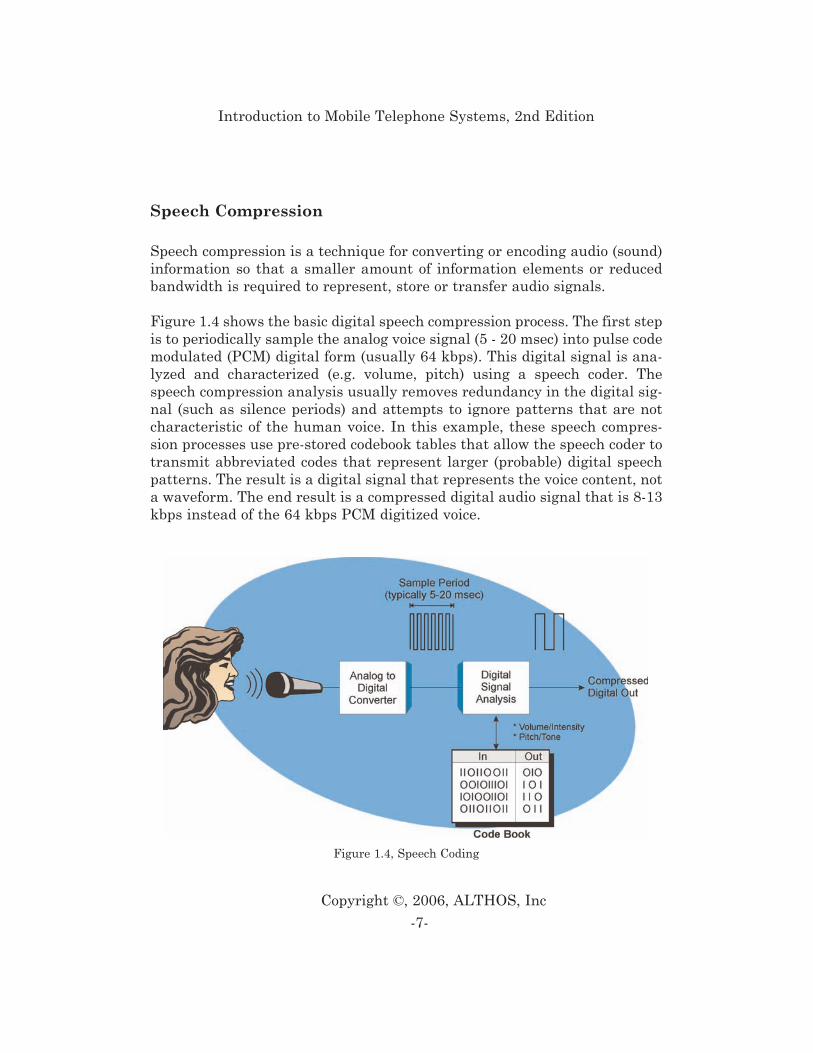
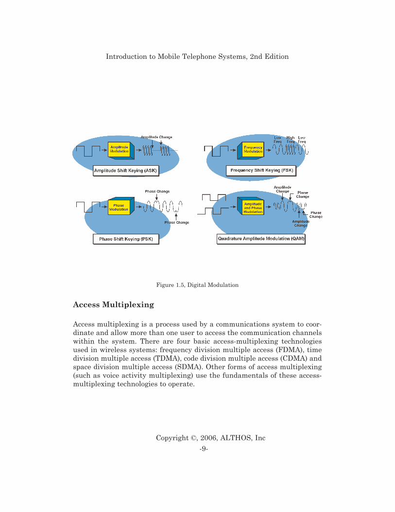
Figure 1.5 shows different forms of digital modulation. This diagram showsASK modulation that turns the carrier signal on and off with the digital sig-nal. FSK modulation shifts the frequency of the carrier signal according tothe on and off levels of the digital information signal. The phase shift mod-ulator changes the phase of the carrier signal in accordance with the digitalinformation signal. This diagram also shows that advanced forms of modu-lation such as QAM can combine amplitude and phase of digital signals.
-8-
Copyright ©, 2006, ALTHOS, Inc
Introduction to Mobile Telephone Systems, 2nd Edition
Access Multiplexing
Access multiplexing is a process used by a communications system to coor-dinate and allow more than one user to access the communication channelswithin the system. There are four basic access-multiplexing technologiesused in wireless systems: frequency division multiple access (FDMA), timedivision multiple access (TDMA), code division multiple access (CDMA) andspace division multiple access (SDMA). Other forms of access multiplexing(such as voice activity multiplexing) use the fundamentals of these access-multiplexing technologies to operate.
-9-
Copyright ©, 2006, ALTHOS, Inc
Introduction to Mobile Telephone Systems, 2nd Edition
Figure 1.5, Digital Modulation
Frequency Division Multiple Access (FDMA)
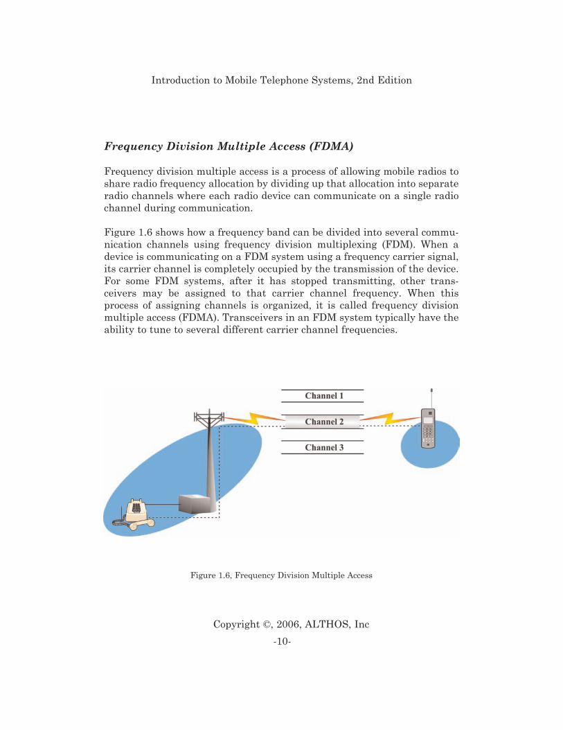
Frequency division multiple access is a process of allowing mobile radios toshare radio frequency allocation by dividing up that allocation into separateradio channels where each radio device can communicate on a single radiochannel during communication.
Figure 1.6 shows how a frequency band can be divided into several commu-nication channels using frequency division multiplexing (FDM). When adevice is communicating on a FDM system using a frequency carrier signal,its carrier channel is completely occupied by the transmission of the device.For some FDM systems, after it has stopped transmitting, other trans-ceivers may be assigned to that carrier channel frequency. When thisprocess of assigning channels is organized, it is called frequency divisionmultiple access (FDMA). Transceivers in an FDM system typically have theability to tune to several different carrier channel frequencies.
-10-
Copyright ©, 2006, ALTHOS, Inc
Introduction to Mobile Telephone Systems, 2nd Edition
Figure 1.6, Frequency Division Multiple Access
Time Division Multiple Access (TDMA)
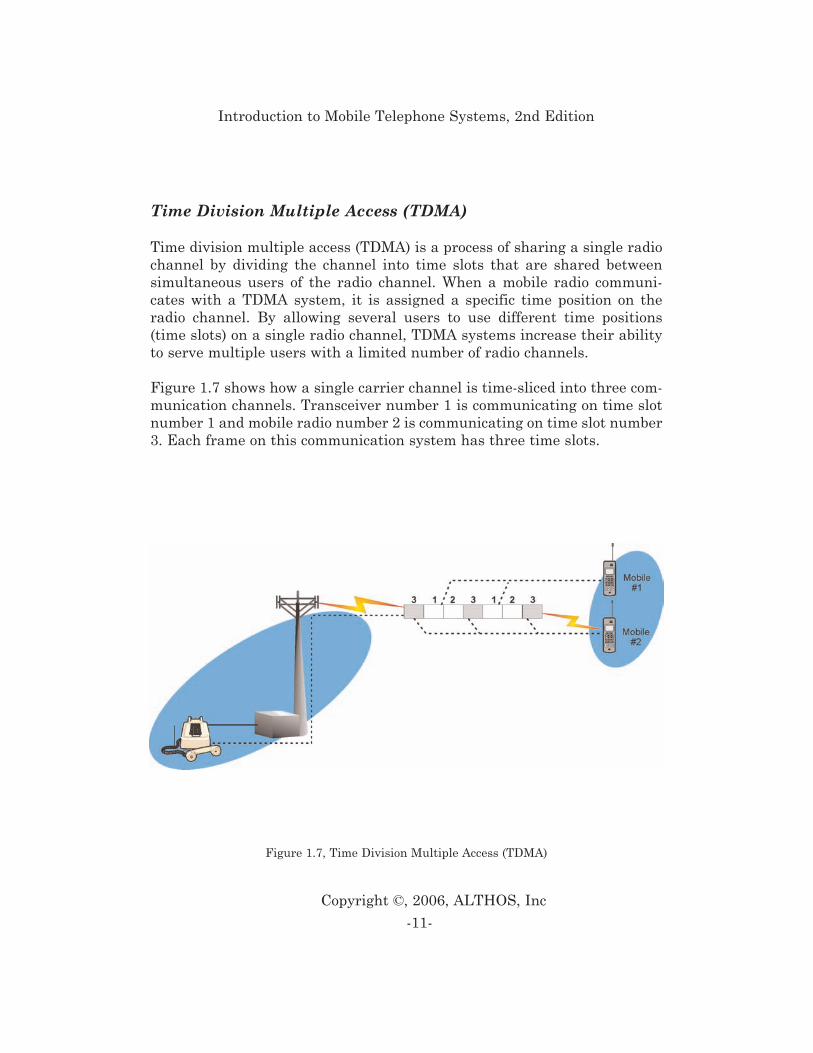
Time division multiple access (TDMA) is a process of sharing a single radiochannel by dividing the channel into time slots that are shared betweensimultaneous users of the radio channel. When a mobile radio communi-cates with a TDMA system, it is assigned a specific time position on theradio channel. By allowing several users to use different time positions(time slots) on a single radio channel, TDMA systems increase their abilityto serve multiple users with a limited number of radio channels.
Figure 1.7 shows how a single carrier channel is time-sliced into three com-munication channels. Transceiver number 1 is communicating on time slotnumber 1 and mobile radio number 2 is communicating on time slot number3. Each frame on this communication system has three time slots.
-11-
Copyright ©, 2006, ALTHOS, Inc
Introduction to Mobile Telephone Systems, 2nd Edition
Figure 1.7, Time Division Multiple Access (TDMA)
Code Division Multiple Access (CDMA)
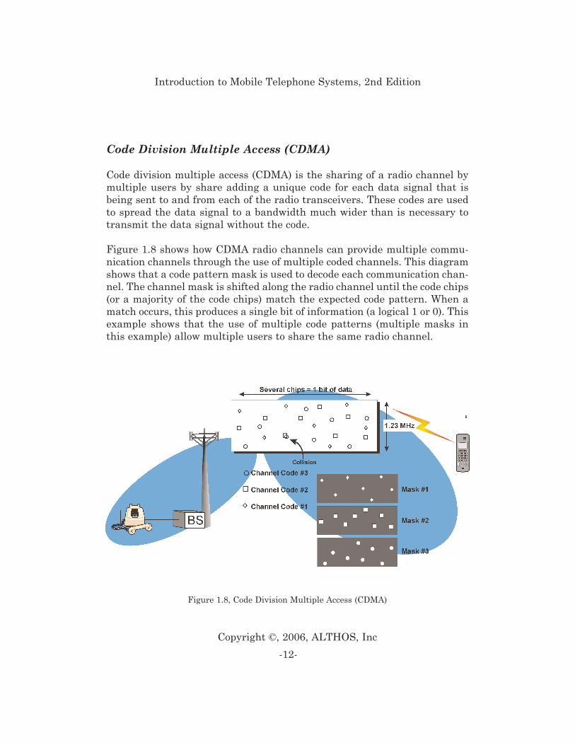
Code division multiple access (CDMA) is the sharing of a radio channel bymultiple users by share adding a unique code for each data signal that isbeing sent to and from each of the radio transceivers. These codes are usedto spread the data signal to a bandwidth much wider than is necessary totransmit the data signal without the code.
Figure 1.8 shows how CDMA radio channels can provide multiple commu-nication channels through the use of multiple coded channels. This diagramshows that a code pattern mask is used to decode each communication chan-nel. The channel mask is shifted along the radio channel until the code chips(or a majority of the code chips) match the expected code pattern. When amatch occurs, this produces a single bit of information (a logical 1 or 0). Thisexample shows that the use of multiple code patterns (multiple masks inthis example) allow multiple users to share the same radio channel.
-12-
Copyright ©, 2006, ALTHOS, Inc
Introduction to Mobile Telephone Systems, 2nd Edition
Figure 1.8, Code Division Multiple Access (CDMA)
Spatial Division Multiple Access (SDMA)
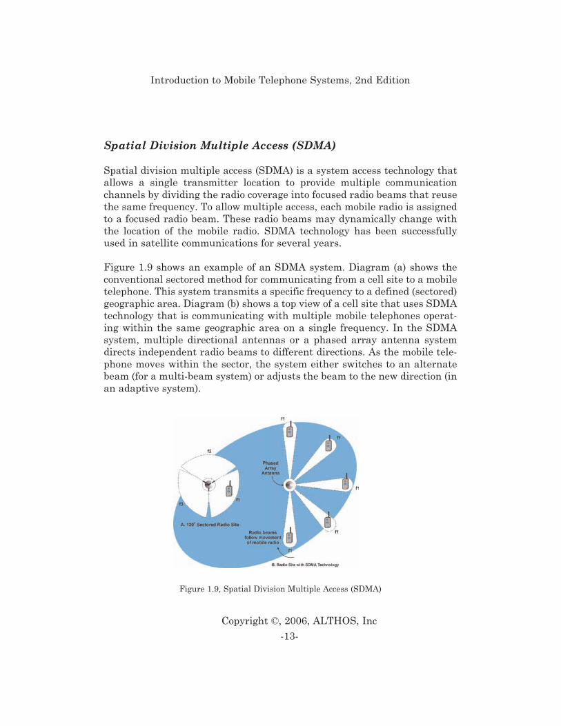
Spatial division multiple access (SDMA) is a system access technology thatallows a single transmitter location to provide multiple communicationchannels by dividing the radio coverage into focused radio beams that reusethe same frequency. To allow multiple access, each mobile radio is assignedto a focused radio beam. These radio beams may dynamically change withthe location of the mobile radio. SDMA technology has been successfullyused in satellite communications for several years.
Figure 1.9 shows an example of an SDMA system. Diagram (a) shows theconventional sectored method for communicating from a cell site to a mobiletelephone. This system transmits a specific frequency to a defined (sectored)geographic area. Diagram (b) shows a top view of a cell site that uses SDMAtechnology that is communicating with multiple mobile telephones operat-ing within the same geographic area on a single frequency. In the SDMAsystem, multiple directional antennas or a phased array antenna systemdirects independent radio beams to different directions. As the mobile tele-phone moves within the sector, the system either switches to an alternatebeam (for a multi-beam system) or adjusts the beam to the new direction (inan adaptive system).
-13-
Copyright ©, 2006, ALTHOS, Inc
Introduction to Mobile Telephone Systems, 2nd Edition
Figure 1.9, Spatial Division Multiple Access (SDMA)
-14-
Copyright ©, 2006, ALTHOS, Inc
Introduction to Mobile Telephone Systems, 2nd Edition
Packet Data
Packet data is the sending of data through a network in small packets (typ-ically under 1000 bytes of information per packet). A packet data systemdivides large quantities of data into small packets for transmission througha switching network that uses the addresses of the packets to dynamicallyroute these packets through a switching network to their ultimate destina-tion. When a data block is divided, the packets are given sequence numbersso that a packet assembler/disassembler (PAD) device can recombine thepackets to the original data block after they have been transmitted throughthe network.
To send packet data on mobile networks, the system is designed to coordi-nate the dynamic assignment and reception of radio packets. The wirelesssystem is connected to packet switching nodes. Packet switching nodes inGSM systems are called GPRS Support Nodes (GSNs). GSNs receive andforward data packets toward their destination.
To add packet radio and packet data switching to a mobile system, this sys-tem can be separated into two separate parts; a voice part and a packet datapart. The voice part connects voice calls to a single location using a circuitswitched connection (circuit path). The packet data part dynamically routespackets towards their destination depending on the address that is con-tained in the data packet.
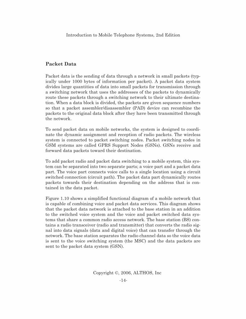
Figure 1.10 shows a simplified functional diagram of a mobile network thatis capable of combining voice and packet data services. This diagram showsthat the packet data network is attached to the base station in an additionto the switched voice system and the voice and packet switched data sys-tems that share a common radio access network. The base station (BS) con-tains a radio transceiver (radio and transmitter) that converts the radio sig-nal into data signals (data and digital voice) that can transfer through thenetwork. The base station separates the radio channel data so the voice datais sent to the voice switching system (the MSC) and the data packets aresent to the packet data system (GSN).
-15-
Copyright ©, 2006, ALTHOS, Inc
Introduction to Mobile Telephone Systems, 2nd Edition
Mobile Devices
Mobile devices (also called access terminals) are input and output devicesthat are used to communicate with a radio site (base stations). Mobiledevices may include removable subscriber identity modules (SIMs) that holdservice subscription information. The common types of available mobiledevices include external radio modems, PCMCIA cards, radio modules, anddual mode mobile telephones.
Subscriber Identity Module (SIM)
The subscriber identity module (SIM) is a small “information” card that con-tains service subscription identity and personal information. This informa-tion includes a phone number, billing identification information and a smallamount of user specific data (such as feature preferences and short mes-
Figure 1.10, Packet Mobile System
sages). This information is stored in the card rather than programming thisinformation into the phone itself. This intelligent card, either credit card-sized (ISO format), or the size of a postage-stamp (Plug-In format), can beinserted into any SIM ready wireless telephone.
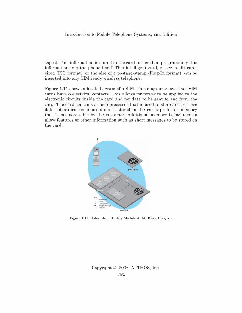
Figure 1.11 shows a block diagram of a SIM. This diagram shows that SIMcards have 8 electrical contacts. This allows for power to be applied to theelectronic circuits inside the card and for data to be sent to and from thecard. The card contains a microprocessor that is used to store and retrievedata. Identification information is stored in the cards protected memorythat is not accessible by the customer. Additional memory is included toallow features or other information such as short messages to be stored onthe card.
-16-
Copyright ©, 2006, ALTHOS, Inc
Introduction to Mobile Telephone Systems, 2nd Edition
Figure 1.11, Subscriber Identity Module (SIM) Block Diagram
PCMCIA Air Cards
The PCMCIA card uses a standard physical and electrical interface that isused to connect memory and communication devices to computers, typicallylaptops. The physical card sizes are similar to the size of a credit card 2.126inches (51.46 mm) by 3.37 inches (69.2 mm) long. There are 4 different cardthickness dimensions: 3.3 (type 1), 5.0 (type 2), 10.5 (type 3), and 16 mm(type 4). WCDMA PCMCIA radio cards can be added to most laptop com-puters to avoid the need of integrating or attaching radio devices.
Embedded Radio Modules
Embedded radio modules are self-contained electronic assemblies that maybe inserted or attached to other electronic devices or systems. Embeddedradio modules may be installed in computing devices such as personal digi-tal assistants (PDAs), laptop computers, and other types of computingdevices that can benefit from wireless data and/or voice connections.
Mobile Telephones
Mobile telephones are radio transceivers (combined transmitter and receive)that convert signals between users (typically people, but not always) andradio signals. Mobile telephones can vary from simple voice units toadvanced multimedia personal digital assistants (PDAs).
External Radio Modems
External radio modems are self-contained radios with data modems thatallow the customer to simply plug the radio device to their USB or Ethernetdata port on their desktop or laptop computer. External modems are com-monly connected to computers via standard connections such as universalserial bus (USB) or RJ-45 Ethernet connections.
-17-
Copyright ©, 2006, ALTHOS, Inc
Introduction to Mobile Telephone Systems, 2nd Edition
To allow for the conversion from analog systems to digital systems, somemobile systems allow for the use of dual mode or multi-mode mobile radios.These mobile radios may be capable of operating on an analog or digitalradio channel or on multiple types of digital channels, depending onwhichever is available. Most dual mode phones prefer to use the most recentversion of digital radio channels in the event both are available (e.g. 3G ispreferred over 2G). This allows them to take an advantage of the additionalcapacity and new features such as short messaging and digital voice quali-ty, as well as offering greater capacity.
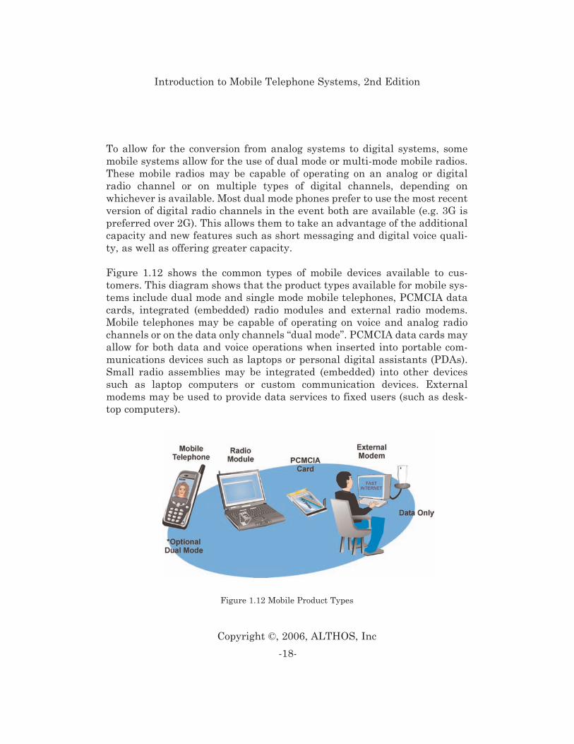
Figure 1.12 shows the common types of mobile devices available to cus-tomers. This diagram shows that the product types available for mobile sys-tems include dual mode and single mode mobile telephones, PCMCIA datacards, integrated (embedded) radio modules and external radio modems.Mobile telephones may be capable of operating on voice and analog radiochannels or on the data only channels “dual mode”. PCMCIA data cards mayallow for both data and voice operations when inserted into portable com-munications devices such as laptops or personal digital assistants (PDAs).Small radio assemblies may be integrated (embedded) into other devicessuch as laptop computers or custom communication devices. Externalmodems may be used to provide data services to fixed users (such as desk-top computers).
-18-
Copyright ©, 2006, ALTHOS, Inc
Introduction to Mobile Telephone Systems, 2nd Edition
Figure 1.12 Mobile Product Types
Mobile Systems
Mobile systems are composed of include base stations (BS), switching sys-tems and various data processing functions. The radio system portion ofmobile networks is called a radio access network (RAN).
Mobile networks inter-connect wireless devices with nearby radio towersthat route calls through switching systems to other wireless telephones toother telephones or data networks. Creating and managing a wireless net-work involves equipment selection and installation, implementation meth-ods, inter-connection to the public switched telephone network (PTSN) andother networks such as the Internet.
The mobile system uses either a mobile switching center (MSC) for voice andmedium-speed data or a packet data service node (PDSN) for packet dataservices. The MSC coordinates the overall allocation and routing of callsthroughout the wireless system. The PDSN ensures packets from the mobiledevices can reach their destination.
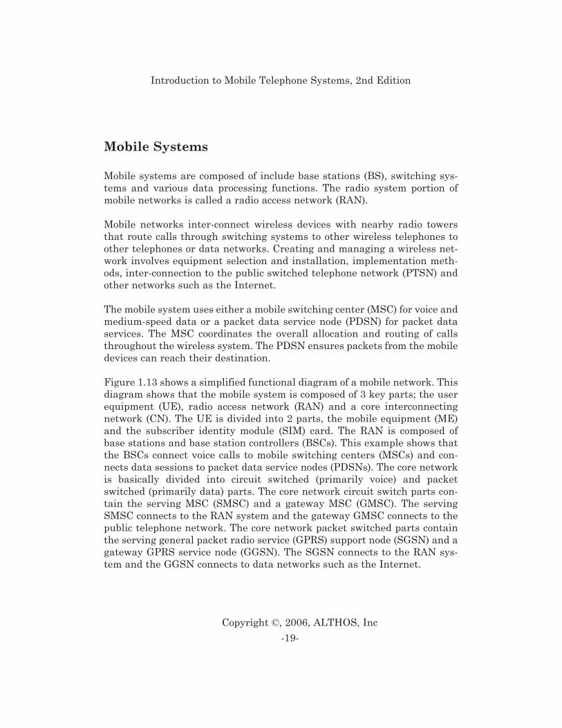
Figure 1.13 shows a simplified functional diagram of a mobile network. Thisdiagram shows that the mobile system is composed of 3 key parts; the userequipment (UE), radio access network (RAN) and a core interconnectingnetwork (CN). The UE is divided into 2 parts, the mobile equipment (ME)and the subscriber identity module (SIM) card. The RAN is composed ofbase stations and base station controllers (BSCs). This example shows thatthe BSCs connect voice calls to mobile switching centers (MSCs) and con-nects data sessions to packet data service nodes (PDSNs). The core networkis basically divided into circuit switched (primarily voice) and packetswitched (primarily data) parts. The core network circuit switch parts con-tain the serving MSC (SMSC) and a gateway MSC (GMSC). The servingSMSC connects to the RAN system and the gateway GMSC connects to thepublic telephone network. The core network packet switched parts containthe serving general packet radio service (GPRS) support node (SGSN) and agateway GPRS service node (GGSN). The SGSN connects to the RAN sys-tem and the GGSN connects to data networks such as the Internet.
-19-
Copyright ©, 2006, ALTHOS, Inc
Introduction to Mobile Telephone Systems, 2nd Edition
Base Stations
Base stations may be stand alone transmission systems or part of a cell siteand is composed of an antenna system (typically a radio tower), building,and base station radio equipment. Base station radio equipment consists ofRF equipment (transceivers and antenna interface equipment), controllers,and power supplies. Base station transceivers have many of the same basicparts as a mobile device. However, base station radios are coordinated bythe mobile system’s BSC and have many additional functions than a mobiledevice.
The radio transceiver section is divided into transmitter and receiver assem-blies. The transmitter section converts a voice or data signal to RF for trans-mission to wireless devices and the receiver section converts RF from thewireless device to voice or data signals routed to the MSC or packet switch-ing network. The controller section commands insertion and extraction ofsignaling information.
Unlike end user wireless devices (such as a mobile telephone or laptop com-puter), the transmitter, receiver, and control sections of an access point may
-20-
Copyright ©, 2006, ALTHOS, Inc
Introduction to Mobile Telephone Systems, 2nd Edition
Figure 1.13, Mobile Network
be grouped into equipment racks. For example, a single equipment rack maycontain all of the RF amplifiers or voice channel cards. Unlike analog orearly-version digital cellular systems that dedicated one transceiver in eachbase station for a control channel, the mobile system combines control chan-nels and voice channels are mixed on a single physical radio channel.
Radio Antenna Towers
Wireless base station antenna heights can vary from a few feet to more thanthree hundred feet. Radio towers raise the height of antennas to providegreater area coverage. There may be several different antenna systemsmounted on the same radio tower. These other antennas may be used forpaging systems, a point to point microwave communication link, or landmobile radio (LMR) dispatch systems. Shared use of towers by differenttypes of radio systems in this way are very common due to the economiesrealized by sharing the cost of the tower and shelter. However, great caremust be taken in the installation and testing to avoid mutual radio inter-ference between the various systems.
Communication Links
Communication links carry both data and digital voice information betweenthe base station and the mobile network. The physical connection options forcommunication links include copper wire, microwave radio, or fiber opticlinks. Duplicate and/or alternate communication links are sometimes usedto help ensure communication may continue in the event of the failure of acommunication line (such as when a cable seeking backhoe cuts a line).
-21-
Copyright ©, 2006, ALTHOS, Inc
Introduction to Mobile Telephone Systems, 2nd Edition
Mobile Switching Center (MSC)
The mobile switching center (MSC) processes requests for service frommobile devices and land line callers, and routes calls between the base sta-tions and the public switched telephone network (PSTN). The MSC receivesthe dialed digits, creates and interprets call-processing tones, and routes thecall paths.
Authentication, Authorization, and Accounting (AAA)
Authentication, Authorization, and Accounting are the processes used invalidating the claimed identity of an end user or a device, such as a host,server, switch, or router in a communication network. Authentication is aprocess of exchanging information between a communications device (typi-cally a user device such as a mobile phone or computing device) and a com-munications network that allows the carrier or network operator to confirmthe true identity of the user (or device). Authorization is the act of grantingaccess rights to a user, groups of users, system, or a process. Accounting isthe method to establish who, or what, performed a certain action, such astracking user connection and logging system users.
Interworking Function (IWF)
Interworking functions are systems and/or processes that attach to a com-munications network that is used to process and adapt information betweendissimilar types of network systems. IWFs in the mobile system may includedata gateways that convert circuit switched data from the MSC to theInternet.
-22-
Copyright ©, 2006, ALTHOS, Inc
Introduction to Mobile Telephone Systems, 2nd Edition
Message Center (MC)
The message center is a node or network function within a communicationsnetwork that accommodates messages sent and received via short messag-ing service (SMS).
Serving General Packet Radio Service Support Node (SGSN)
A serving general packet radio service support node is a switching node thatcoordinates the operation of packet radios that are operating within its ser-vice coverage range. The SGSN operates in a similar process of a MSC anda VLR, except the SGSN performs packet switching instead of circuitswitching. The SGSN registers and maintains a list of active packet dataradios in its network and coordinates the packet transfer between themobile radios.
Gateway GPRS Support Node (GGSN)
A gateway GPRS support node is a packet switching system that is used toconnect a GPRS packet data communication network to other packet net-works such as the Internet.
Base Station Controller (BSC)
A base station controller is an automatic coordinator (controller) in a mobilesystem that allows one or more base transceiver stations (BTS) to commu-nicate with a mobile switching center and/or a packet data communicationsystem. A BSC is called a Radio Network Controller (RNC) in the WCDMAsystem.
-23-
Copyright ©, 2006, ALTHOS, Inc
Introduction to Mobile Telephone Systems, 2nd Edition
Voice Message System (VMS)
The voice mail system is a telecommunications system that allows a sub-scriber to receive and play back messages from a remote location (such as aPBX telephone or mobile phone). The VMS consists primarily of memorystorage (for messages), telephone interfaces (to connect to the communica-tion system), and message recording, playback, and control features (typi-cally via DTMF tones).
Public Switched Telephone Network (PSTN)
Public switched telephone networks are communication systems that areavailable to the public to allow users to interconnect communication devices.Public telephone networks within countries and regions are standard inte-grated systems of transmission and switching facilities, signaling proces-sors, and associated operations support systems that allow communicationdevices to communicate with each other when they operate.
Public Packet Data Network (PPDN)
A packet data network is a network that is generally available for commer-cial users (the public). An example of a PPDN is the Internet.
Network Databases
Network databases are information storage and retrieval systems that areaccessible by a network. There are many network databases in the mobilenetwork. Some of the key network databases include a master subscriberdatabase (home location register), temporary active user subscriber data-base (visitor location register), an unauthorized or suspect user database(equipment identity register), billing database, and authorization and vali-dation center (authentication).
-24-
Copyright ©, 2006, ALTHOS, Inc
Introduction to Mobile Telephone Systems, 2nd Edition
Home Location Register (HLR)
The home location register (HLR) is a subscriber database containing eachcustomer’s international mobile subscriber identity (IMSI) and internation-al mobile equipment identifier (IMEI) to uniquely identify each customer.There is usually only one HLR for each carrier even though each carrier mayhave many MSCs.
The HLR holds each customer’s user profile which includes the selected longdistance carrier, calling restrictions, service fee charge rates, and otherselected network options. The subscriber can change and store the changesfor some feature options in the HLR (such as call forwarding.) The MSC sys-tem controller uses this information to authorize system access and processindividual call billing.
The HLR is a magnetic storage device for a computer (commonly called ahard disk). Subscriber databases are critical, so they are usually regularlybacked up, typically on tape or CDROM, to restore the information if theHLR system fails.
Visitor Location Register (VLR)
The visitor location register (VLR) contains a subset of a subscriber’s HLRinformation for use while a mobile telephone is active on a particular MSC.The VLR holds both visiting and home customer’s information. The VLReliminates the need for the MSC to continually check with the mobile tele-phone’s HLR each time access is attempted. The user’s required HLR infor-mation is temporarily stored in the VLR memory and then erased eitherwhen the wireless telephone registers with another MSC , registers inanother system or after a specified period of inactivity.
Equipment Identity Register (EIR)
The equipment identity register is a database that contains the identity oftelecommunications devices (such as wireless telephones) and the status ofthese devices in the network (such as authorized or not-authorized). TheEIR is primarily used to identify wireless telephones that may have been
-25-
Copyright ©, 2006, ALTHOS, Inc
Introduction to Mobile Telephone Systems, 2nd Edition
stolen or have questionable usage patterns that may indicate fraudulentuse. The EIR has three types of lists; white, black and gray. The white listholds known good mobile devices. The black list holds invalid (barred)mobile device. The gray list holds mobile devices that may be suspect forfraud or are being tested for validation.
Billing Center (BC)
A separate database (called the billing center) keeps records on billing. Thebilling center receives individual call records from MSCs and other networkequipment. The switching records (connection and data transfer records) areconverted into call detail records (CDRs) that hold the time, type of service,connection points, and other details about the network usage that is associ-ated with a specific user identification code. These billing records are thentransferred via tape or data link to a separate computer typically by elec-tronic data interchange (EDI) to a billing system or company that can settlebills between different service providers (a clearinghouse company).
Authentication Centre (AuC)
The Authentication Centre stores and processes information that isrequired to validate (authenticate) the identity of a wireless device beforeservice is provided. During the authentication procedure, the AuC providesinformation to the system to allow it to validate the mobile device.
Number Portability Database (NPDB)
Number portability is the ability for a telephone number to be transferredbetween different service providers. This allows customers to change serviceproviders without having to change telephone numbers. Number portabilityinvolves three key elements: local number portability, service portabilityand geographic portability. To enable number portability, the mobile systemmaintains a number portability database (NPDB). This database helps toroute calls to their destination which may have an assigned telephone num-ber that is different (number has been ported) than the destination phonenumber.
-26-
Copyright ©, 2006, ALTHOS, Inc
Introduction to Mobile Telephone Systems, 2nd Edition
IP Backbone Network
A backbone network is the core infrastructure of a network that connectsseveral major network components together. A backbone system is usuallya high-speed communications network such as ATM or FDDI. The mobilesystem uses a backbone network that can provide end-to-end IP transmis-sion capability.
Backbone network is a communications network that connects the primaryswitches or nodes within the network. The backbone network is usuallycomposed of high-speed switches and communication lines.
The focus on using IP communication allows carriers to use off-the-shelf IPnetwork equipment. This typically lowers the equipment cost (due to a largeselection of vendors and equipment options), reduces operation and mainte-nance costs due to one type of system to maintain (less training and process-es), and allows for the use of standard software (traffic monitoring and man-agement).
Mobile System Operation
Mobile system operation is the set of tasks performed to complete key oper-ations: initialization of information when the subscriber unit is turned on,monitoring of control information, accessing the system, and maintainingcommunication sessions.
When a mobile device is first turned on, it gathers its initial information(initializes) by scanning the available radio channels to find control chan-nels. If it finds control channel (or its pilot signal), it determines the type ofservice capability and it will begin to synchronize (time align) with the chan-nel to obtain system broadcast information.
If it finds more than one control channel, it will usually tune to the radiochannel with the strongest or best quality signal level. If the mobile devicedoes not find any control channels, it may begin to scan an alternate chan-
-27-
Copyright ©, 2006, ALTHOS, Inc
Introduction to Mobile Telephone Systems, 2nd Edition
nel type if the user has programmed the mobile device to allow access to analternative system (if the device has multi-mode capability). If it finds a con-trol channels from the other type of system, it will synchronize with the con-trol channel and gather its system broadcast information.
The system broadcast information provides the information needed by themobile device to monitor for incoming calls (paging messages) and to coor-dinate how to access the system (power level and maximum number of sys-tem access attempts).
After the mobile device has gathered its initial information (initialized), itwill typically register with the system. This allows the system to routeincoming calls to the cell site(s) that are able to communicate with themobile device. The mobile device will continually register (sending shortmessages) to the system as it moves through new radio coverage areas.
When a mobile device desires to obtain service from a mobile system, itsends an access request message. Before attempting to access the system,the mobile device must first listen to the control channel to determine if thesystem is idle (not currently busy) serving access requests from other mobiledevices.
When a call is received by the wireless system for the mobile device, the sys-tem sends a call alert (page) message to the radio coverage area(s) where themobile device has last registered. After the mobile device has initializedwith the system, it constantly listens to the paging channels for page mes-sages (its own identification number).
After the mobile device has gained the attention of the system and has beengranted access to services, a communication session (connected mode) isestablished. During the communication session, a voice path and/or datapath may be opened (communication sessions). While the mobile device is inconnected mode, other processes may simultaneously happen such as chan-nel handover.
-28-
Copyright ©, 2006, ALTHOS, Inc
Introduction to Mobile Telephone Systems, 2nd Edition
Initialization
Initialization is the process of a mobile device initially finding an availableradio channel, synchronizing with the system and obtaining system para-meters from the pilot channel, synchronization channel (SCH), and broad-cast channel (BCH) to determine the information requirements for accessand communication.
Initialization phase begins when the mobile device first powers on. It ini-tially looks to the stored information or information contained in its sub-scriber identity module (SIM) card for a preferred control channel list. Ifthere is no list, the mobile device scans all of the available radio channels tofind a control channel.
Idle
During idle mode, the mobile device monitors several different control chan-nels to acquire system access parameters, determine if it has been paged orreceived an order, initiate a call (if the user is placing a call) or to start adata session (if the user has started a data application).
After obtaining the system parameters, the mobile device continuously mon-itors the broadcast channel for changes in system parameters, includingsystem identification and access information. If the mobile device has dis-continuous reception (sleep mode) capability, and if the system supports it,the mobile device turns off its receiver and other non-essential circuitry fora fixed number of burst periods. The system knows that it has commandedthe mobile device to sleep, so it does not send pages designated for thatmobile device during the sleep period.
The mobile device then monitors the paging control channel to determine ifit has received a page. If a call is to be received, an internal flag is set indi-cating that the mobile device is entering access mode in response to a page.If the system sends an order such as a registration message, an internal flagis set indicating that the mobile device is attempting access in response to
-29-
Copyright ©, 2006, ALTHOS, Inc
Introduction to Mobile Telephone Systems, 2nd Edition
an order. When a user initiates a call, an internal flag is set indicating thatthe access attempt is a call origination, and dialed digits will follow theaccess request.
Access Control and Initial Assignment
Access control and initial assignment is the process of gaining the attentionof the system, obtaining authorization to use system services and the initialassignment to communication channel to setup a communication session.
Access control and initial assignment occurs when a mobile device respondsto a page (incoming connection request), desires to setup a call, or anyattempt by the mobile device. Access to the mobile system is a random (atany time) occurrence (not usually preplanned.) To avoid access “collisions”between mobile devices, a seizure collision avoidance process is used. Beforea mobile device attempts access to the system, it first waits until the chan-nel is available (not busy serving other users). The mobile device thenbegins transmitting an access request message (called an access probe) on arandom access control channel at very low power. An access attempt (anaccess probe) contains a preamble that is followed by the access channeldata message. The access request preamble uses a predefined sequence thatallows the system to easily detect an access request message. The accessrequest indicates the type of service the mobile device is requesting (e.g. callorigination or a response to a paging message).
If an access request message does not gain the attention of the system in ashort period of time, the mobile device will increase its transmitter powerlevel and send another access request message. This process will repeatuntil either the system responds to the access request or if the mobile devicereaches a maximum allowable transmission power level established by thesystem.
If the system acknowledges the mobile device’s request for service, themobile device will send additional information to the system that allows itto setup a dedicated communications channel where conversation or datatransmission can begin.
-30-
Copyright ©, 2006, ALTHOS, Inc
Introduction to Mobile Telephone Systems, 2nd Edition
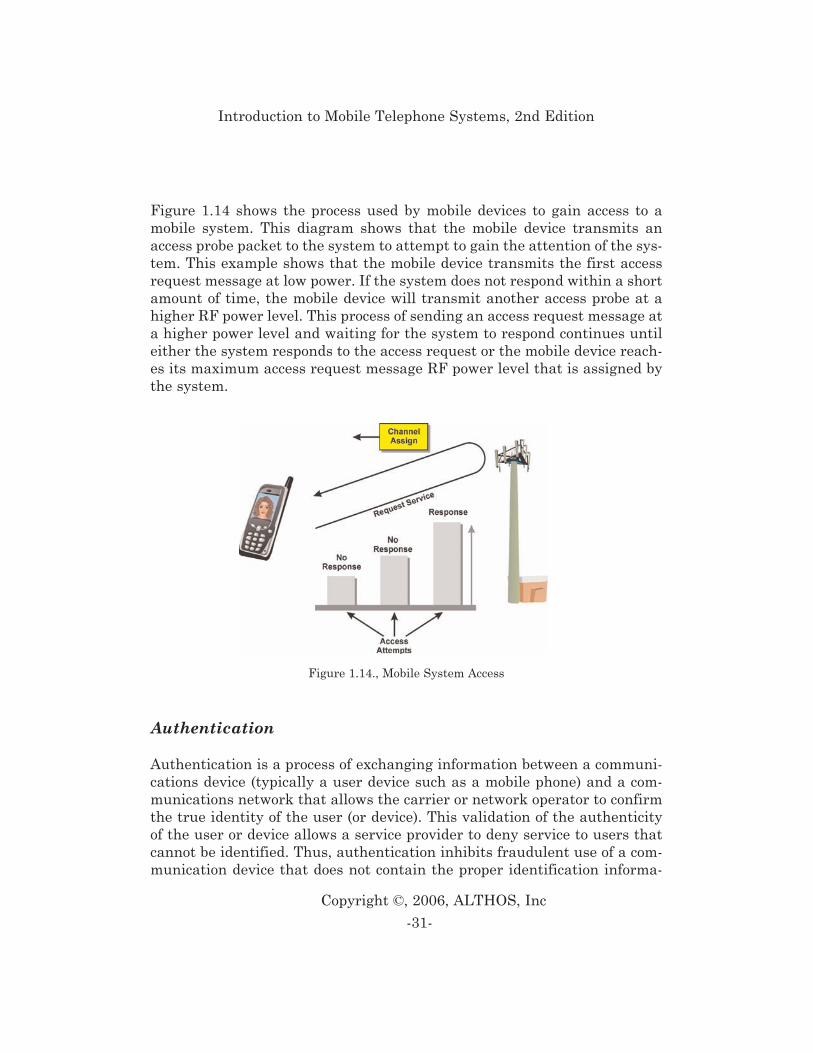
Figure 1.14 shows the process used by mobile devices to gain access to amobile system. This diagram shows that the mobile device transmits anaccess probe packet to the system to attempt to gain the attention of the sys-tem. This example shows that the mobile device transmits the first accessrequest message at low power. If the system does not respond within a shortamount of time, the mobile device will transmit another access probe at ahigher RF power level. This process of sending an access request message ata higher power level and waiting for the system to respond continues untileither the system responds to the access request or the mobile device reach-es its maximum access request message RF power level that is assigned bythe system.
Authentication
Authentication is a process of exchanging information between a communi-cations device (typically a user device such as a mobile phone) and a com-munications network that allows the carrier or network operator to confirmthe true identity of the user (or device). This validation of the authenticityof the user or device allows a service provider to deny service to users thatcannot be identified. Thus, authentication inhibits fraudulent use of a com-munication device that does not contain the proper identification informa-
-31-
Copyright ©, 2006, ALTHOS, Inc
Introduction to Mobile Telephone Systems, 2nd Edition
Figure 1.14., Mobile System Access
tion. The mobile system may require the mobile device to authenticate withthe system during the system access process.
Paging
Paging is a process used to alert mobile devices when they are receiving acall, command, or message. Mobile devices listen for paging messages fortheir identification code (associated with their telephone number) on a pag-ing channel.
After a mobile device has registered with the system, it may be assigned toa paging group. The use of paging groups allows a mobile telephone to sleepduring paging groups that it does not belong to. The paging group is identi-fied by a paging indicator (PI) that is provided at the beginning of the pag-ing message group. The mobile device first reads the PI to determine if itshould remain awake to receive the paging group or if it can go to sleep asits identification code is not associated with the particular paging group.
Connected Mode
Connected mode is the process of managing the communication sessionwhen a mobile device is transferring data to and from a Base Station. Whenin the connected mode, the base transceiver station (BTS) continuously con-trols the mobile device during the communication session. These controltasks include power level control, hand-over, alerting, etc. The base stationexercise control during the communication session through dedicated con-trol channels.
To enter the connected mode, the base station must open a communicationchannel with the mobile device. When the connection is opened, each frameor packet that is received by the base station can be transferred to theassigned communication line (for a voice call) or IP address (for a data com-munications session). When a communication session is complete (e.g. theuser presses end or closes their email or web browsing application), the con-nection is closed and the base station may assign other users to the radioresources.
-32-
Copyright ©, 2006, ALTHOS, Inc
Introduction to Mobile Telephone Systems, 2nd Edition
The mobile device does not have to continuously transmit data while in theconnected mode. When in the connected mode, the base station associates(maps) the radio link to the circuit switched communication channel (forvoice) or to an IP address (for data). When the connected mode is used fordata transmission such as web browsing, the typical data transmissionactivity is less than 10%. Other mobile devices can use the channels duringinactive data transmission periods allowing a system to serve many (possi-bly hundreds) simultaneous data users for each mobile telephone radiochannel.
During the connected mode, communication session processing tasksinclude the insertion and extraction of control messages that allow functionssuch as power control monitoring and control, handover operation, adding orterminating additional communication sessions (logical channels), and othermobile device operational functions.
Packet Data Scheduling Algorithm
A packet data-scheduling algorithm is a program that coordinates thesequences of processes or information. The packet data-scheduling algo-rithm in the mobile system is used to coordinate the flow of data to multiplepacket data users.
Mobile data usage such as Internet web browsing involves data transmis-sion that is not continuous. The ratio of data transmitted by a single devicecompared to the overall data transmission by all the devices is the activityfactor. The lower the activity factor, the higher the number of mobile datadevices that can access the system.
Packet scheduling can assign different priority levels based on user andapplication types. Packets for specific types of users such as public safetyofficers can be given higher priority. Packets for specific applications suchas IP Telephony can be given priority over other applications such as webbrowsing or email access.
-33-
Copyright ©, 2006, ALTHOS, Inc
Introduction to Mobile Telephone Systems, 2nd Edition
Registration
Registration is the process that is used by mobile devices to inform the wire-less system of their location and availability to receive communications ser-vices (such as incoming calls). The reception of registration requests allowsa wireless system to route incoming messages to the radio base station ortransmitter where the mobile device has recently registered.
The process of registration is typically continuous. Mobile devices registerwhen they power on, when they move between new radio coverage areas,when requested by the system, and when the mobile device is power off.
Because the registration process consumes resources of the system (channelcapacity and system-servicing capacity), there is a tradeoff between regu-larly maintaining registration information and the capacity of the system.During periods of high system usage activity, registration processes may bereduced.
Analog Systems (1st Generation)
Analog cellular is an industry term given to first generation (1G) cellularsystems that transmit voice information using a form of analog modulation(e.g. FM). Analog cellular systems may have digital control channels. Analogcellular systems primarily provide voice and low-speed data communicationservices over a wide geographic area.
Analog cellular systems use very narrow radio channel (small amount ofbandwidth) that varies from 10 kHz to 30 kHz. Analog systems usually sendcontrol information in digital (data) form. The data signaling rates deter-mine how fast messages can be sent on control channels. The RF power levelof mobile telephones and how the power level is controlled ordinarily deter-mines how far away the mobile telephone can operate from the base station(radio tower).
-34-
Copyright ©, 2006, ALTHOS, Inc
Introduction to Mobile Telephone Systems, 2nd Edition
Regardless of the size and type of radio channels, all cellular and PCS sys-tems allow for full duplex operation. Full duplex operation is the ability tohave simultaneous communications between the caller and the called per-son. This means a mobile telephone must be capable of simultaneouslytransmitting and receiving to the radio tower. The radio channel from themobile telephone to the radio tower is called the uplink and the radio trans-mission channel from the base station to the mobile telephone is called thedownlink. The uplink and downlink radio channels are normally separatedby 45 MHz to 80 MHz.
In early mobile radio systems, a mobile telephone scanned the limited num-ber of available channels until it found an unused one, which allowed it toinitiate a call. Because the analog cellular systems in use today have hun-dreds of radio channels, a mobile telephone cannot scan them all in a rea-sonable amount of time. To quickly direct a mobile telephone to an availablechannel, some of the available radio channels are dedicated as control chan-nels. Most cellular systems use two types of radio channels, control channelsand voice channels. Control channels carry only digital messages and sig-nals, which allow the mobile telephone to retrieve system control informa-tion and compete for access.
Control channels only carry control information such as paging (alert) andchannel assignment messages. Voice channels are primarily used to trans-fer voice information. However, voice channels must also be capable of send-ing and receiving some digital control messages to allow for necessary fre-quency and power changes during a call.
Current analog systems serve only one subscriber at a time on a radio chan-nel so the number of radio channels available influence system capacity.However, a typical subscriber uses the system for only a few minutes a day,on a daily basis, and many subscribers share a single channel. As a rule, 20- 32 subscribers share each radio channel [2], depending upon the averagetalk time per hour per subscriber. Generally, a cell with 50 channels cansupport 1000 - 1600 subscribers.
-35-
Copyright ©, 2006, ALTHOS, Inc
Introduction to Mobile Telephone Systems, 2nd Edition
The basic operation of an analog cellular system involves initiation of thephone when it is powered on, listening for paging messages (idle), attempt-ing access when required and conversation (or data) mode.
When a mobile telephone is first powered on, it initializes itself by search-ing (scanning) a predetermined set of control channels and then tuning tothe strongest one. During the initialization mode, it listens to messages onthe control channel to retrieve system identification and setup information.
After initialization, the mobile telephone enters the idle mode and waits tobe paged for an incoming call and senses if the user has initiated (dialed) acall (access). When a call begins to be received or initiated, the mobile tele-phone enters system access mode to try to access the system via a controlchannel. When it gains access, the control channel sends an initial voicechannel designation message indicating an open voice channel. The mobiletelephone then tunes to the designated voice channel and enters the con-versation mode. As the mobile telephone operates on a voice channel, thesystem uses Frequency Modulation (FM) similar to commercial broadcastFM radio. To send control messages on the voice channel, the voice infor-mation is either replaced by a short burst (blank and burst) message or insome systems, control messages can be sent along with the audio signal.
A mobile telephone’s attempt to obtain service from a cellular system isreferred to as access. Mobile telephones compete on the control channel toobtain access from a cellular system. Access is attempted when a commandis received by the mobile telephone indicating the system needs to servicethat mobile telephone (such as a paging message indicating a call to bereceived) or as a result of a request from the user to place a call. The mobiletelephone gains access by monitoring the busy/idle status of the controlchannel both before and during transmission of the access attempt message.If the channel is available, the mobile station begins to transmit and thebase station simultaneously monitors the channel’s busy status.Transmissions must begin within a prescribed time limit after the mobilestation finds that the control channel access is free, or the access attempt isstopped on the assumption that another mobile telephone has possiblygained the attention of the base station control channel receiver.
-36-
Copyright ©, 2006, ALTHOS, Inc
Introduction to Mobile Telephone Systems, 2nd Edition
If the access attempt succeeds, the system sends out a channel assignmentmessage commanding the mobile telephone to tune to a cellular voice chan-nel. When a subscriber dials the mobile telephone to initiate a call, it iscalled “origination”. A call origination access attempt message is sent to thecellular system that contains the dialed digits, identity information alongwith other information. If the system allows service, the system will assigna voice channel by sending a voice channel designator message, if a voicechannel is available. If the access attempt fails, the mobile telephone waitsa random amount of time before trying again. The mobile station uses a ran-dom number generating (an internal algorithm) to determine the randomtime to wait. The design of the system minimizes the chance of repeated col-lisions between different mobile stations, which are both trying to access thecontrol channel since each one waits a different random time interval beforetrying again if they have already collided on their first, simultaneousattempt.
To receive calls, a mobile telephone is notified of an incoming call by aprocess called paging. A page is a control channel message that contains thetelephone’s Mobile Identification Number (MIN) or telephone number of thedesired mobile phone. When the telephone determines it has been paged, itresponds automatically with a system access message that indicates itsaccess attempt is the result of a page message and the mobile telephonebegins to ring to alert the customer of an incoming telephone call. When thecustomer answers the call (user presses “SEND” or “TALK”), the mobiletelephone transmits a service request to the system to answer the call. Itdoes this by sending the telephone number and an electronic serial numberto provide the users identity.
After a mobile telephone has been commanded to tune to a radio voice chan-nel, it sends mostly voice or other customer information. Periodically, con-trol messages may be sent between the base station and the mobile tele-phone. Control messages may command the mobile telephone to adjust its
-37-
Copyright ©, 2006, ALTHOS, Inc
Introduction to Mobile Telephone Systems, 2nd Edition
power level, change frequencies, or request a special service (such as threeway calling).
To conserve battery life, a mobile phone may be permitted by the base sta-tion to only transmit when it senses the mobile telephone’s user is talking.When there is silence, the mobile telephone may stop transmitting for briefperiods of time (several seconds). When the mobile telephone user begins totalk again, the transmitter is turned on again. This is called discontinuoustransmission.
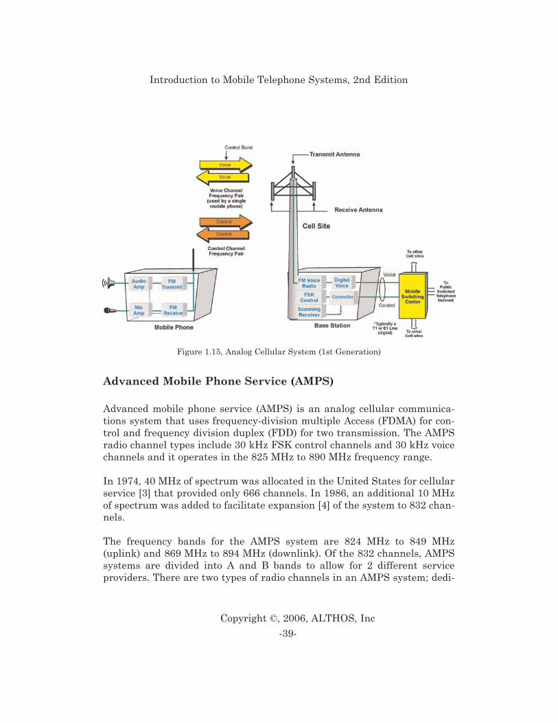
Figure 1.15 shows a basic analog cellular system. This diagram shows thatthere are two types of radio channels; control channels and voice channels.Control channels typically use frequency shift keying (FSK) to send controlmessages (data) between the mobile phone and the base station. Voice chan-nels typically use FM modulation with brief bursts of digital information toallow control messages (such as handoff) during conversation. Base stationstypically have two antennas for receiving and one for transmitting. Dualreceiver antennas increases the ability to receive the radio signal frommobile telephones which typically have a much lower transmitter powerlevel than the transmitters in the base station. Base stations are connectedto a mobile switching center (MSC) typically by a high speed telephone lineor microwave radio system. This interconnection must allow both voice andcontrol information to be exchanged between the switching system and thebase station. The MSC is connected to the telephone network to allow mobiletelephones to be connected to standard landline telephones.
There are many types of analog and digital cellular systems in use through-out the world. Analog systems include AMPS, TACS, JTACS, NMT, MCSand CNET.
-38-
Copyright ©, 2006, ALTHOS, Inc
Introduction to Mobile Telephone Systems, 2nd Edition
Advanced Mobile Phone Service (AMPS)
Advanced mobile phone service (AMPS) is an analog cellular communica-tions system that uses frequency-division multiple Access (FDMA) for con-trol and frequency division duplex (FDD) for two transmission. The AMPSradio channel types include 30 kHz FSK control channels and 30 kHz voicechannels and it operates in the 825 MHz to 890 MHz frequency range.
In 1974, 40 MHz of spectrum was allocated in the United States for cellularservice [3] that provided only 666 channels. In 1986, an additional 10 MHzof spectrum was added to facilitate expansion [4] of the system to 832 chan-nels.
The frequency bands for the AMPS system are 824 MHz to 849 MHz(uplink) and 869 MHz to 894 MHz (downlink). Of the 832 channels, AMPSsystems are divided into A and B bands to allow for 2 different serviceproviders. There are two types of radio channels in an AMPS system; dedi-
-39-
Copyright ©, 2006, ALTHOS, Inc
Introduction to Mobile Telephone Systems, 2nd Edition
Figure 1.15, Analog Cellular System (1st Generation)
cated control channels and voice channels. On each system (A or B), mobiletelephones scan and tune to one of 21 dedicated control channels to listen forpages and compete for access to the system. The control channel continu-ously sends system identification information and access control informa-tion. Although the control channel data rate is 10 kbps, messages arerepeated 5 times, which reduces the effective channel rate to below 2 kbps.This allows a control channel to send 10 to 20 pages per second.
The AMPS cellular system is a frequency duplex with its channels separat-ed by 45 MHz. The control channel and voice channel signals are transferredat 10 kbps. AMPS cellular phones have three classes of maximum outputpower. A class 1 mobile telephone has a maximum power output of 6 dBW(4 Watts), class 2 has a maximum output power of 2 dBW (1.6 Watts), andthe class 3 units are capable of delivering only -2 dBW (0.6 Watts). The out-put power can be adjusted in 4 dB steps and has a minimum output powerof -22 dBW (approximately 6 milliwatts).
Total Access Communication System (TACS)
Total access communications system is an analog mobile telephone systemthat is an enhanced version of AMPS (analog cellular). It was developed anddeployed in the United Kingdom and it primarily operates on the 900 MHzfrequency range. In the late 1990s, TACS systems began converting to GSMsystems.
The Total Access Communication System (TACS) is very similar to the USEIA-553 AMPS system. Its primary differences include changes to the radiochannel frequencies, radio channel bandwidths and data signaling rates.The TACS was introduced to the U.K. in 1985. After its introduction in theUK in 1985, over 25 countries offered TACS service. The introduction of theTACS system was very successful and the system was expanded to add morechannels through what is called Extended TACS (ETACS).
-40-
Copyright ©, 2006, ALTHOS, Inc
Introduction to Mobile Telephone Systems, 2nd Edition
The TACS system was deployed in 25kHz radio channels compared to the30kHz channels used in AMPS. This narrower radio bandwidth reduced thedata speed of the signaling channel.
The frequency ranges of most TACS systems are 890 MHz to 915 MHz forthe uplink and 935 MHz to 960 MHz for the downlink. The TACS systemwas initially allocated at 25 MHz although 10 MHz of the 25 MHz wasreserved for future pan-European systems in the UK. An additional 16 MHzof radio channel bandwidth was added to allow for Extended TACS(ETACS). The ETACS system is a frequency duplex system with its chan-nels separated by 45 MHz.
The control channel and voice channel signals are transferred at 8 kbps.There are 4 power classes for ETACS mobile telephones. Class 1 mobile tele-phones have a maximum output of 10 Watts, class 2 has 4 Watts, class 3 has1.6 Watts, and class 4 has 0.6 Watts. Similar to AMPS, mobile telephonescan be adjusted in 4 dB steps and have a minimum transmit power level ofapproximately 6 milliwatts.
The TACS system has also been modified for use in Japan. This Japaneseversion is called JTACS. The only significant changes were the frequencybands and number of channels. The TACS system has also been modified tocreate the Narrowband TACS (NTACS) system. NTACS reduced the radiochannel bandwidth from 25 kHz to 12.5 kHz and changed the in-band 8 kbpssignaling on the voice channel to 100 bps sub-band digital signaling.
Nordic Mobile Telephone (NMT)
Nordic mobile telephone is a mobile cellular telephone system that wasintroduced to Europe in 1981. The NMT system has been deployed on twofrequency bands; 450 MHz and 900 MHz. These systems use FM (analog)radio modulation. In the 1990s, NMTS systems were converted to the GSM(digital) system.
-41-
Copyright ©, 2006, ALTHOS, Inc
Introduction to Mobile Telephone Systems, 2nd Edition
The NMT 450 system is a low capacity system and NMT 900 that is a highcapacity system. The Nordic mobile telephone (NMT) system was developedby the telecommunications administrations of Sweden, Norway, Finland,and Denmark to create a compatible mobile telephone system in the Nordiccountries [5]. The first commercial NMT 450 cellular system was availableat the end of 1981. Due to the rapid success of the initial NMT 450 systemand limited capacity of the original system design, the NMT 900-system ver-sion was introduced in 1986.
The NMT 450 system uses a lower frequency (450 MHz) and higher maxi-mum transmitter power level. This allows a larger cell site coverage areaswhile the NMT 900 system uses a higher frequency (approximately thesame 900 MHz band used for TACS and GSM) and a lower maximum trans-mitter power, which increases system capacity. NMT 450 and NMT 900 sys-tems can co-exist which permits them to use the same switching center [6].This allowed some NMT service providers to start offering service with anNMT 450 system and progress up to a NMT 900 system when the need aris-es.
Some operations of the NMT systems are very different from most other cel-lular systems. When NMT mobile telephones access the cellular system,they can either find an unused voice channel and negotiate access directlyor begin conversation without the assistance of a dedicated control channel.Because scanning for free voice channels can be very time consuming, theNMT 900 system does allow for the use of a dedicated control channel thatis called the calling channel. The NMT 900 system also allows discontinu-ous reception, which increases the standby time of the portable phones.
The NMT 450 system is frequency duplex with 180 channels (except Finlandwhich only has 160 channels) [7]. The radio channel bandwidth is 25 kHzand the frequency duplex spacing is 10 MHz. The NMT 900 system has 999channels or 1999 interleaved channels.
Signaling on the NMT systems is performed at 1200 bps on the control (call-ing) channel (NMT 900) and voice channel. Because of the slow signalingrate and robust error detection/correction capability, no repeated messagesare necessary.
-42-
Copyright ©, 2006, ALTHOS, Inc
Introduction to Mobile Telephone Systems, 2nd Edition
NMT 450 base stations can transmit up to 50W. This high power combinedwith the lower 450 MHz frequency allows cell site size of up to approxi-mately 40 km radius. NMT 900 base stations are limited to a maximum of25W that allows a maximum cell size radius of up to approximately 20 km[8].
There are three power levels (high, medium, and low) for NMT mobilephones and two power levels (high and low) for portables. NMT 450 mobiletelephone power levels are: High 15W, Medium 1.5W, and Low 0.15W, NMT450 portable telephones; High 1.0W, Low 0.1W. NMT 900 mobile tele-phones: High 6.0W, Medium 1.0W, Low 0.1W and NMT 900 portable tele-phones: High 1.0W, Low 0.1W.
The NMT system is unique as it included various types of anti-fraud pro-tection. NMT mobile telephones hold a three-digit password that is stored inthe telephone and cellular switching center and is unknown to the customer.This password is sent to the cellular system during system access along withthe mobile telephone number. The NMT system has also added a SubscriberIdentity Security (SIS) system that provides additional anti-fraud protec-tion. Not all NMT telephones have SIS capability.
Narrowband AMPS (NAMPS)
Narrowband AMPS is a cellular system that allows the use of either 30 kHzor 10 kHz FM modulated (analog) channels. The NAMPS system was devel-oped to increase the serving system capacity by allowing each base stationto contain more channels (transceivers). NAMPS adds sub-band signalingoperation to the signaling control channels used in the AMPS system.
NAMPS was commercially introduced by Motorola in late 1991 and wasdeployed worldwide. Like the existing AMPS technology, NAMPS uses ana-log FM radio for voice transmissions. The distinguishing feature of NAMPSis its use of a “narrow” 10 kHz bandwidth for radio channels, a third of thesize of AMPS channels. Because more of these narrower radio channels canbe installed in each cell site, NAMPS systems can serve more subscribers
-43-
Copyright ©, 2006, ALTHOS, Inc
Introduction to Mobile Telephone Systems, 2nd Edition
than AMPS systems without adding new cell sites. NAMPS also shifts somecontrol commands to the sub-audible frequency range to facilitate simulta-neous voice and data transmissions.
In 1991, the first NAMPS standard, named IS-88, evolved from the USAMPS specification (EIA-553). The IS-88 standard identified parametersneeded to begin designing NAMPS radios, such as radio channel bandwidth,type of modulation, and message format. During development, the NAMPSspecification benefited from the narrowband JTACS radio system specifica-tions. During the following years, advanced features such as ESN authenti-cation, caller ID, and short messaging were added to the NAMPS specifica-tion.
Japanese Mobile Cellular System (MCS)
Japan launched the world’s first commercial cellular system in 1979.Because this system had achieved great success, several different types ofcellular systems have evolved in Japan. These include the MCS-L1, MCS-L2, JTACS and NTACS systems.
The MCS-L1 was the first cellular system in Japan, which was developedand operated by NTT. The system operates in the 800 MHz band. The chan-nel bandwidth is 25 kHz and the signaling is at 300 bps. The control chan-nels are simulcast from all base stations in the local area. This limits themaximum capacity of the MCS-L1 system.
Because the MCS-L1 system could only serve a limited number of cus-tomers, the MCS-L2 system was developed. It uses the same frequencybands as the MCS-L1 system. The radio channel bandwidth was reducedfrom 25 kHz to 12.5 kHz with 6.25 kHz interleaving. This gives the MCS-L2system 2,400 channels. The control channels transfer information at 2,400
-44-
Copyright ©, 2006, ALTHOS, Inc
Introduction to Mobile Telephone Systems, 2nd Edition
bps and the voice channels can use either in-band (blank and burst) signal-ing at 2,400 bps or sub-band digital audio signaling at 150 bps. MCS-L2mobile telephones have diversity reception (similar to diversity receptionused in base stations). While this increases the cost and size of the mobiletelephones, it also increases the performance and range of the cellular sys-tem.
CNET
CNET is an analog cellular system that is used in Germany, Portugal, andSouth Africa [9]. The first CNET system started operation in Germany in1985. The primary objective of the CNET system was to bridge the gap ofcellular systems in Germany until the digital European system could beintroduced [10].
The CNET system operates at 450 MHz with 4.44 MHz transmit and receivebands. The frequency bands are 461.3 to 465.74 MHz and 451.3 to 455.74MHz. The primary channel bandwidth is 20 kHz with 10 kHz channel inter-leaving.
The CNET system continuously exchanges digital information between themobile telephone and the base station. Every 12.5 msec, 4 bits of informa-tion are sent during compressed speech periods [11]. CNET mobile tele-phones also use an Identification Card (IC), which slides into the telephoneto identify the customer. This allows customers to use any compatible CNETtelephone.
MATS-E
The MATS-E system is used in France and Kuwait [12]. The MATS-E sys-tem combines many of the features used in different cellular systems.MATS-E uses the standard European mobile telephone frequency bands;890-915 MHz and 935-960 MHz. The channel bandwidth is 25 kHz that pro-vides 1,000 channels. The MATS-E is a frequency duplex system separatedby 45 MHz. Each cell site has at least one dedicated control channel with a
-45-
Copyright ©, 2006, ALTHOS, Inc
Introduction to Mobile Telephone Systems, 2nd Edition
signaling rate of 2400 bps. Voice channels use FM modulation with sub-band digital audio signaling with a data rate of 150 bps
Digital Cellular Systems (2nd Generation)
Digital cellular is an industry term given to the new cellular technology thattransmits voice information in digital form. This differs from Analog cellu-lar in that the method of transmission for voice/data information is bymeans of digital signals. Digital mobile radio systems are often character-ized by their type of access technology (TDMA or CDMA). The access tech-nology determines how that digital information is transferred to and fromthe cellular system.
Digital cellular systems can usually serve several subscribers on a singleradio channel at the same time. Depending on the type of system, this canrange from 3 to over 20. To allow this, almost all digital cellular systemsshare the fundamental characteristics of digitizing and compressing voiceinformation to accomplish this. This allows a single radio channel to bedivided into several sub-channels (communication channels). Each commu-nication channel can serve a single customer.
Because each subscriber typically uses the cellular system for only a fewminutes a day, several subscribers can share each one of these communica-tion channels during the day. As a rule, 20 - 32 subscribers can share eachcommunication channel. So, if a digital radio channel has 8 communicationschannels (sub-channels), a cell site with 25 radio channels can support 4000to 6400 subscribers (25 radio channels x 8 users per channel x 20 to 32 sub-scribers per communication channel).
Digital cellular systems use two key types of communication channels, con-trol channels and voice channels. A control channel on a digital system isusually one of the sub-channels on the radio channel. This allows digital sys-tems to combine a control channel and one or more voice channels on a sin-gle radio channel. The portion of the radio channel that is dedicated as acontrol channel carries only digital messages and signals that allow the
-46-
Copyright ©, 2006, ALTHOS, Inc
Introduction to Mobile Telephone Systems, 2nd Edition
mobile telephone to retrieve system control information and compete foraccess. The other sub-channels on the radio channel carry voice or datainformation.
The basic operation of a digital cellular system involves initiation of thephone when it is powered on, listening for paging messages (idle), attempt-ing access when required and conversation (or data) mode.
When a digital mobile telephone is first powered on, it initializes itself bysearching (scanning) a predetermined set of control channels and then tun-ing to the strongest one. During the initialization mode, it listens to mes-sages on the control channel to retrieve system identification and setupinformation. Compared to analog systems, digital systems have more com-munication and control channels. This can result in the mobile phone tak-ing more time to search for control channels. To quickly direct a mobile tele-phone to an available control channel, digital systems use several processesto help a mobile telephone to find an available control channel. Theseinclude having the phone memorize its last successful control channel loca-tion, a table of likely control channel locations and a mechanism for point-ing to the location of a control channel on any of the operating channels.
After a digital mobile telephone has initialized, it enters an idle mode whereit waits to be paged for an incoming call or for the user to initiate a call.When a call begins to be received or initiated, the mobile telephone enterssystem access mode to try to access the system via a control channel. Whenit gains access, the control channel sends a digital traffic channel designa-tion message indicating an open communications channel. This channelmay be on a different time slot on the same frequency or to a time slot on adifferent frequency. The digital mobile telephone then tunes to the desig-nated communications channel and enters the conversation mode. As themobile telephone operates on a digital voice channel, the digital system com-monly uses some form of phase modulation (PM) to send and receive digitalinformation.
A mobile telephone’s attempt to obtain service from a cellular system isreferred to as “access”. Digital mobile telephones compete on the controlchannel to obtain access from a cellular system. Access is attempted when a
-47-
Copyright ©, 2006, ALTHOS, Inc
Introduction to Mobile Telephone Systems, 2nd Edition
command is received by the mobile telephone indicating the system needs toservice that mobile telephone (such as a paging message indicating a call tobe received) or as a result of a request from the user to place a call. Digitalmobile telephones usually have the ability to validate their identities moresecurely during access than analog mobile telephones. This is made possibleby a process called authentication. Authentication processes share secretdata between the digital mobile phone and the cellular system.
If the authentication is successful, the system sends out a channel assign-ment message commanding the mobile telephone to change to a new com-munication channel and conversation can begin.
After a mobile telephone has been commanded to tune to a radio voice chan-nel, it sends digitized voice or other customer data. Periodically, controlmessages may be sent between the base station and the mobile telephone.Control messages may command the mobile telephone to adjust its powerlevel, change frequencies, or request a special service (such as three waycalling). To send control messages while the digital mobile phone is trans-ferring digital voice, the voice information is either replaced by a short burst(called blank and burst or fast signaling), or else control messages can besent along with the digitized voice signals (called slow signaling).
Most digital telephones automatically conserve battery life as they transmitonly for short periods of time (bursts). In addition to savings through digitalburst transmission, digital phones ordinarily have the capability of discon-tinuous transmission that allows the inhibiting of the transmitter duringperiods of user silence. When the mobile telephone user begins to talk again,the transmitter is turned on again. The combination of the power savingsallows some digital mobile telephones to have 2 to 5 times the battery life inthe transmit mode.
Digital technology increases system efficiency by voice digitization, speechcompression (coding), channel coding, and the use of spectrally efficientradio signal modulation. Standard voice digitization in the Public SwitchedTelephone Network (PSTN) produces a data rate of 64 kilobits per second(kbps). Because transmitting a digital signal via radio requires about 1 Hzof radio bandwidth for each bps, an uncompressed digital voice signal wouldrequire more than 64 kHz of radio bandwidth. Without compression, this
-48-
Copyright ©, 2006, ALTHOS, Inc
Introduction to Mobile Telephone Systems, 2nd Edition
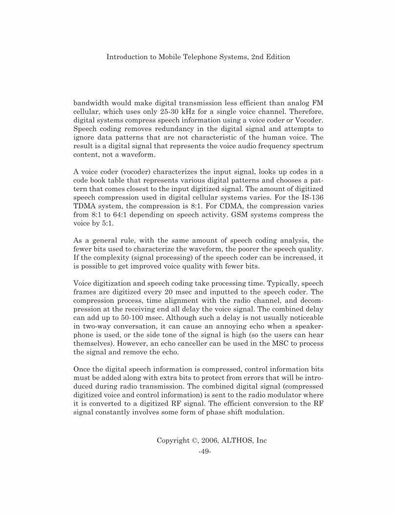
bandwidth would make digital transmission less efficient than analog FMcellular, which uses only 25-30 kHz for a single voice channel. Therefore,digital systems compress speech information using a voice coder or Vocoder.Speech coding removes redundancy in the digital signal and attempts toignore data patterns that are not characteristic of the human voice. Theresult is a digital signal that represents the voice audio frequency spectrumcontent, not a waveform.
A voice coder (vocoder) characterizes the input signal, looks up codes in acode book table that represents various digital patterns and chooses a pat-tern that comes closest to the input digitized signal. The amount of digitizedspeech compression used in digital cellular systems varies. For the IS-136TDMA system, the compression is 8:1. For CDMA, the compression variesfrom 8:1 to 64:1 depending on speech activity. GSM systems compress thevoice by 5:1.
As a general rule, with the same amount of speech coding analysis, thefewer bits used to characterize the waveform, the poorer the speech quality.If the complexity (signal processing) of the speech coder can be increased, itis possible to get improved voice quality with fewer bits.
Voice digitization and speech coding take processing time. Typically, speechframes are digitized every 20 msec and inputted to the speech coder. Thecompression process, time alignment with the radio channel, and decom-pression at the receiving end all delay the voice signal. The combined delaycan add up to 50-100 msec. Although such a delay is not usually noticeablein two-way conversation, it can cause an annoying echo when a speaker-phone is used, or the side tone of the signal is high (so the users can hearthemselves). However, an echo canceller can be used in the MSC to processthe signal and remove the echo.
Once the digital speech information is compressed, control information bitsmust be added along with extra bits to protect from errors that will be intro-duced during radio transmission. The combined digital signal (compresseddigitized voice and control information) is sent to the radio modulator whereit is converted to a digitized RF signal. The efficient conversion to the RFsignal constantly involves some form of phase shift modulation.
-49-
Copyright ©, 2006, ALTHOS, Inc
Introduction to Mobile Telephone Systems, 2nd Edition
Figure 1.16 shows a basic digital cellular system. This diagram shows thatthere usually is only one type of digital radio channel called a digital trafficchannel (DTC). The digital radio channel is ordinarily sub-divided into con-trol channels and digital voice channels. Both the control channels and voicechannels use the same type of digital modulation to send control and con-tent data between the mobile phone and the base station. When used forvoice, the digital signal is usually a compressed digital signal that is from aspeech coder. When conversation is in progress, some of the digital bits areusually dedicated for control information (such as handoff). Similar to ana-log systems, digital base stations have two antennas that increase the abil-ity to receive weak radio signals from mobile telephones. Base stations areconnected to a mobile switching center (MSC) normally by a high speed tele-phone line or microwave radio system. This interconnection may allow com-pressed digital information (directly from the speech coder) to increase thenumber of voice channels that can be shared on a single connection line. TheMSC is connected to the telephone network to allow mobile telephones to beconnected to standard landline telephones.
-50-
Copyright ©, 2006, ALTHOS, Inc
Introduction to Mobile Telephone Systems, 2nd Edition
Figure 1.16, Digital Cellular System (2nd Generation)
Second generation (2G) cellular is a term commonly used to describe digitalcellular radio technology with advanced messaging and data transmissioncapabilities. The types of 2nd generation digital cellular systems includeGSM, IS-136 TDMA and CDMA.
Global System for Mobile Communication (GSM)
The Global System for Mobile Communications (GSM) is a global digitalradio system that uses Time Division Multiple Access (TDMA) technology.GSM is a digital cellular technology that was initially created to provide asingle-standard pan-European cellular system. The GSM system is a digi-tal-only system and was not designed to be backward compatible with theestablished analog systems.
GSM began development in 1982, and the first commercial GSM digital cel-lular system was activated in 1991. GSM technology has evolved to be usedin a variety of systems and frequencies (900 MHz, 1800 MHz and 1900 MHz)including Personal Communications Services (PCS) in North America andPersonal Communications Network (PCN) systems throughout the world.
When communicating in a GSM system, users can operate on the same radiochannel simultaneously by sharing time slots. The GSM cellular systemallows 8 mobile telephones to share a single 200 kHz bandwidth radio car-rier waveform for voice or data communications. To allow duplex operation,GSM voice communication is conducted on two 200 kHz wide carrier fre-quency waveforms.
The GSM system has several types of control channels that carry systemand paging information, and coordinates access like the control channels onanalog systems. The GSM digital control channels have many more capa-bilities than analog control channels such as broadcast message paging,extended sleep mode, and others. Because the GSM control channels useonly a portion (one or more slots), they typically co-exist on a single radiochannel with other time slots that are used for voice communication.
-51-
Copyright ©, 2006, ALTHOS, Inc
Introduction to Mobile Telephone Systems, 2nd Edition
A GSM carrier transmits at a bit rate of 270 kbps. A single GSM digital
radio channel or time slot is capable of transferring only 1/8th of that, whichis about 33 kbps of information (actually less than that, due to the use ofsome bit time for non-information purposes such as synchronization bits).
Time intervals on full rate GSM channels are divided into frames with 8time slots on two different radio frequencies. One frequency is for transmit-ting from the mobile telephone; the other is for receiving to the mobile tele-phone. During a voice conversation at the mobile set, one time slot period isdedicated for transmitting, one for receiving, and six remain idle. Themobile telephone uses some of the idle time slots to measure the signalstrength of surrounding cell carrier frequencies in preparation for handover.
On the 900 MHz band, GSM digital radio channels transmit on one fre-quency and receive on another frequency 45 MHz higher, but not at thesame time. On the 1.9 GHz band, the difference between transmit andreceive frequencies is 80 MHz. The mobile telephone receives a burst of dataon one frequency, then transmits a burst on another frequency, and thenmeasures the signal strength of at least one adjacent cell, before repeatingthe process.
North American TDMA (IS-136 TDMA)
The North American TDMA system (IS-136) is a digital system that usesTDMA access technology. It evolved from the IS-54 specification that wasdeveloped in North America in the late 1980’s to allow the gradual evolutionof the AMPS system to digital service. The IS-136 system is sometimesreferred to as Digital AMPS (DAMPS) or North American digital cellular(NADC).
In 1988, the Cellular Telecommunications Industry Association created adevelopment guideline for the next generation of cellular technology forNorth America. This guideline was called the User PerformanceRequirements (UPR) and the Telecommunications Industry Association(TIA) used this guideline to create a TDMA digital standard, called IS-54.This digital specification evolved from the original EIA-553 AMPS specifi-
-52-
Copyright ©, 2006, ALTHOS, Inc
Introduction to Mobile Telephone Systems, 2nd Edition
cation. The first revision of the IS-54 specification (Rev 0) identified thebasic parameters (e.g. time slot structure, type of radio channel modulation,and message formats) needed to begin designing TDMA cellular equipment.There have been several enhancements to IS-54 since its introduction andin 1995; IS-54 was incorporated as part of the IS-136 specification.
A primary feature of the IS-136 systems is their ease of adaptation to theexisting AMPS system. Much of this adaptability is due to the fact that IS-136 radio channels retain the same 30 kHz bandwidth as AMPS systemchannels. Most base stations can therefore replace TDMA radio units inlocations previously occupied by AMPS radio units. Another factor in favorof adaptability is that new dual mode mobile telephones were developed tooperate on either IS-136 digital traffic (voice and data) channels or the exist-ing AMPS radio channels as requested in the CTIA UPR document. Thisallows a single mobile telephone to operate on any AMPS system and usethe IS-136 system whenever it is available.
The IS-136 specification concentrates on features that were not present inthe earlier IS-54 TDMA system. These include longer standby time, shortmessage service functions, and support for small private or residential sys-tems that can coexist with the public systems. In addition, IS-136 defines adigital control channel to accompany the Digital Traffic Channel (DTC). Thedigital control channel allows a mobile telephone to operate in a single dig-ital-only mode. Revision A of the IS-136 specification now supports opera-tion in the 800 MHz range for the existing AMPS and DAMPS systems aswell as the newly allocated 1900MHz bands for PCS systems. This permitsdual band, dual mode phones (800 MHz and 1900 MHz for AMPS andDAMPS). The primary difference between the two bands is that mobile tele-phones cannot transmit using analog signals at 1900MHz.
The IS-136 cellular system allows for mobile telephones to use either 30 kHzanalog (AMPS) or 30 kHz digital (TDMA) radio channels. The IS-136 TDMAradio channel allows multiple mobile telephones to share the same radio fre-quency channel by time-sharing. All IS-136 TDMA digital radio channelsare divided into frames with 6 time slots. The time slots used for the corre-spondingly numbered forward and reverse channels are time-related so thatthe mobile telephone does not simultaneously transmit and receive.
-53-
Copyright ©, 2006, ALTHOS, Inc
Introduction to Mobile Telephone Systems, 2nd Edition
The IS-136 system allows a standard time slot on a TDMA radio channel tobe used as a digital control channel (DCC). The DCC carries the same sys-tem and paging information as the analog control channel (ACC). In addi-tion to the control messages, the DCC has more capabilities than the ACCsuch as extended sleep mode, short message service (SMS), private and pub-lic control channels, and others.
The total bit rate of the carrier frequency waveform is 48.6 kbps. This istime-shared and some of the transmitted bits are used for synchronizationand other control purposes; this results in a user-available data rate of 13kbps. Some of the 13 kbps are used for error detection and correction, so only8 kbps of data are available for full rate digitally coded speech.
The RF power levels for the mobile phones are almost exactly the same asfor the AMPS telephones. The primary difference in the power levels is areduction in minimum power level that mobile telephones can be instructedto reduce to. This allows for very small cell coverage areas, typically the sizeof cells that would be used for wireless office or home cordless systems.
Extended TDMA (E-TDMA)TM
Extended TDMATM was developed by Hughes Network Systems in 1990 asan extension to the existing IS-136 TDMA industry standard. ETDMA usesthe existing TDMA radio channel bandwidth and channel structure. Itsreceivers are tri-mode as they can operate in AMPS, TDMA, or ETDMAmodes. While a TDMA system assigns a mobile telephone fixed time slotnumbers for each call, ETDMA dynamically assigned time slots on an asneeded basis. The ETDMA system contains a half-rate speech coder (4 kb/s)that reduces the number of information bits that must be transmitted andreceived each second. This makes use of voice silence periods to inhibit slottransmission so other users may share the transmit slot. The overall bene-fit is that more users can share the same radio channel equipment andimproved radio communications performance. The combination of a low bitrate speech coder, voice activity detection and interference averagingincreases the radio channel efficiency to beyond 10 times the existing AMPScapacity.
-54-
Copyright ©, 2006, ALTHOS, Inc
Introduction to Mobile Telephone Systems, 2nd Edition
ETDMA radio channels are structured into the same frames and slots struc-tures as the standard IS-54 radio channels. Some or all of the time slots onall of the radio channels are shared for ETDMA communication, which issimilar to IS-54 and IS-136 radio channels, or else slots can be shared on dif-ferent frequencies. When a Mobile telephone is operating in extended mode,the ETDMA system must continually coordinate time slot and frequencychannel assignments. The ETDMA system performs this by using a timeslot control system. On an ETDMA capable radio channel some of the timeslots are dedicated as control slots on an as needed basis. ETDMA systemscan assign an AMPS channel, a TDMA full-rate or half-rate channel, or anETDMA channel. The existing 30 kHz AMPS control channels are used toassign analog voice and digital traffic channels
In an ETDMA system, some of the radio channels include a control slot thatcoordinates time slot allocation. This usually accounts for an estimated 15%of available time slots in a system. The control time slots assign an ETDMAsubscriber to voice time slots on multiple radio channels.
ETDMA uses the following process to allocate time slots from moment tomoment as needed. The cellular radio maintains constant communicationswith the Base Station through the control time slot. When a conversationbegins, the cellular radio uses the control slot to request a voice time slotfrom the Base Station. Through the control slot, the Base Station assigns avoice time slot and sets the cellular radio to transmit in that assigned voicetime slot. During each momentary lull in phone conversation, the transmit-ting cellular radio gives up its voice time slot, which is then placed back intothe Base Station’s pool of available time slots.
When a cellular radio is ready to receive a voice conversation, the BaseStation uses the control slot to tell it which voice time slot has the conver-sation. The cellular radio receiver then tunes to the appropriate slot.Through the control slot, the Base Station constantly monitors the cellularradio to determine whether it has given up a slot or needs a slot. In turn, thecellular radio constantly monitors the control slot to learn which time slotcontains voice conversation being sent to it.
-55-
Copyright ©, 2006, ALTHOS, Inc
Introduction to Mobile Telephone Systems, 2nd Edition
Integrated Dispatch Enhanced Network (iDEN)
Integrated Dispatch Enhanced Network (iDEN) a digital radio system thatprovides for voice, dispatch and data services. iDEN was formerly calledMotorola Integrated Radio System (MIRS). iDEN was deployed in 1996 forenhanced specialized mobile radio (E-SMR) service. The iDEN system radiochannel bandwidth is 25 kHz and it is divided into frames that have 6 timesslots per frame. The iDEN system allows 6 mobile radios to simultaneouslyshare a single radio channel for dispatch voice quality and up to 3 mobileradios can simultaneously share a radio channel for cellular like voice qual-ity.
Code Division Multiple Access (IS-95 CDMA)
Code Division Multiple Access (CDMA) system (IS 95) is a digital cellularsystem that uses CDMA access technology. IS-95 technology was initiallydeveloped by Qualcomm in the late 1980’s. CDMA cellular service begantesting in the United States in San Diego, California during 1991. In 1995,IS-95 CDMA commercial service began in Hong Kong and now many CDMAsystems are operating throughout the world, including a 1.9 GHz all-digitalsystem in the USA that has been operating since November 1996.
Spread spectrum radio technology has been used for many years in militaryapplications. CDMA is a particular form of spread spectrum radio technolo-gy. In 1989, CDMA spread spectrum technology was presented to the indus-try standards committee but it did not meet with immediate approval. Thestandards committee had just resolved a two-year debate between TDMAand FDMA and was not eager to consider another access technology.
The IS-95 CDMA system allows for voice or data communications on eithera 30 kHz AMPS radio channel (when used on the 800 MHz cellular band) ora new 1.25 MHz CDMA radio channel. The IS-95 CDMA radio channelallows multiple mobile telephones to communicate on the same frequency atthe same time by special coding of their radio signals.
-56-
Copyright ©, 2006, ALTHOS, Inc
Introduction to Mobile Telephone Systems, 2nd Edition
CDMA radio channels carry control, voice, and data signals simultaneouslyby dividing a single traffic channel (TCH) into different sub-channels. Eachof these channels is identified by a unique code. When operating on a CDMAradio channel, each user is assigned to a code for transmission and recep-tion. Some codes in the TCH transfer control channel information while oth-ers transfer voice channel information.
The control channel that is part of a digital traffic channel on a CDMA sys-tem has new advanced features. This digital control channel (DCC) carriessystem and paging information, and coordinates access similar to the ana-log control channel (ACC). The DCC has many more capabilities than theACC such as a precision synchronization signal, extended sleep mode andothers. Because each CDMA radio channel has many codes, more than onecontrol channel can exist on a single CDMA radio channel and the CDMAcontrol channels co-exist with other coded channels that are used for voice.
The IS-95 CDMA cellular system has several key attributes that are differ-ent from other cellular systems. The same CDMA radio carrier frequenciesmay be optionally used in adjacent cell sites, which eliminates the need forfrequency planning. The wide-band radio channel provides less severe fad-ing, which the inventors claim results in consistent quality voice transmis-sion under varying radio signal conditions. The CDMA system is compatiblewith the established access technology and it allows analog (EIA-553) anddual mode (IS-95) subscribers to use the same analog control channels.Some of the voice channels are replaced by CDMA digital transmissions,allowing several users to be multiplexed (shared) on a single RF channel. Aswith other digital technologies, CDMA produces capacity expansion byallowing multiple users to share a single digital RF channel.
The IS-95 CDMA radio channel divides the radio spectrum into wide 1.25MHz digital radio channels. CDMA radio channels differ from those of othertechnologies in that CDMA multiplies (and therefore spreads the spectrumbandwidth of) each signal with a unique pseudo-random noise (PN) codethat identifies each user within a radio channel. CDMA transmits digitizedvoice and control signals on the same frequency band. Each CDMA radiochannel contains the signals of many ongoing calls (voice channels) togeth-er with pilot, synchronization, paging, and access (control) channels. Digital
-57-
Copyright ©, 2006, ALTHOS, Inc
Introduction to Mobile Telephone Systems, 2nd Edition
mobile telephones select the signal they are receiving by correlating (match-ing) the received signal with the proper PN sequence. The correlationenhances the power level of the selected signal and leaves others un-enhanced.
Each IS-95 CDMA radio channel is divided into 64 separate logical (PNcoded) channels. A few of these channels are used for control, and theremainders carry voice information and data. Because CDMA transmits dig-ital information combined with unique codes, each logical channel can trans-fer data at different rates (e.g. 4800 b/s, 9600 b/s).
CDMA systems use a maximum of 64 coded (logical) traffic channels, butthey cannot always use all of these. A CDMA radio channel of 64 trafficchannels can transmit at a maximum information throughput rate ofapproximately 192 kbps [13], so the combined data throughput for all userscannot exceed 192 kbps. To obtain a maximum of 64 communication chan-nels for each CDMA radio channel, the average data rate for each usershould approximate 3 kbps. If the average data rate is higher, less than 64traffic channels can be used. CDMA systems can vary the data rate for eachuser dependent on voice activity (variable rate speech coding), therebydecreasing the average number of bits per user to about 3.8 kbps [14]).Varying the data rate according to user requirement allows more users toshare the radio channel but with slightly reduced voice quality. This iscalled soft capacity limit.
In 1997 the CDMA Development Group (CDG) registered the trademark
cdmaOneTM as a label to identify second-generation digital systems basedon the IS-95 standard and related technologies.
Japanese Personal Digital Cellular (PDC)
The PDC system is a TDMA technology with a radio interface that is verysimilar to IS-136, in that it has six timeslots and an almost identical datarate, and a core network architecture that is very similar to GSM. PDCoperates in both the 900 MHz and 1,400 MHz regions of the radio spectrum.
-58-
Copyright ©, 2006, ALTHOS, Inc
Introduction to Mobile Telephone Systems, 2nd Edition
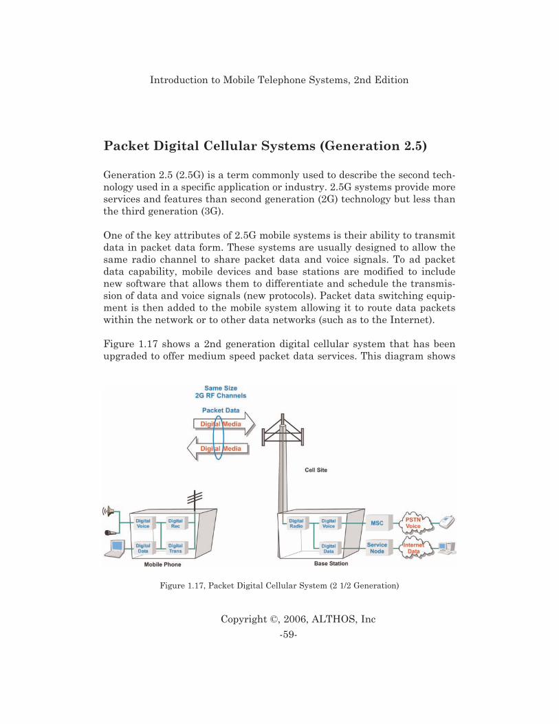
Packet Digital Cellular Systems (Generation 2.5)
Generation 2.5 (2.5G) is a term commonly used to describe the second tech-nology used in a specific application or industry. 2.5G systems provide moreservices and features than second generation (2G) technology but less thanthe third generation (3G).
One of the key attributes of 2.5G mobile systems is their ability to transmitdata in packet data form. These systems are usually designed to allow thesame radio channel to share packet data and voice signals. To ad packetdata capability, mobile devices and base stations are modified to includenew software that allows them to differentiate and schedule the transmis-sion of data and voice signals (new protocols). Packet data switching equip-ment is then added to the mobile system allowing it to route data packetswithin the network or to other data networks (such as to the Internet).
Figure 1.17 shows a 2nd generation digital cellular system that has beenupgraded to offer medium speed packet data services. This diagram shows
-59-
Copyright ©, 2006, ALTHOS, Inc
Introduction to Mobile Telephone Systems, 2nd Edition
Figure 1.17, Packet Digital Cellular System (2 1/2 Generation)
that the existing 2nd generation digital radio channel bandwidth is reused.In some cases, the modulation technology has been changed to allow forhigher data transfer rates. In all cases, the digital traffic channel (DTC) isupgraded to allow for both circuit switched and packet data transmissioncapability. This is accomplished by dividing the digital radio channel intomore control channels and digital communication channels (voice and data).This diagram shows that the digital radio channel can be connected to theexisting mobile communication network for voice services or it can be con-nected (sometimes simultaneously) to a packet data network (such as theInternet) to allow for multimedia communication services.
The types of packet based 2nd generation digital cellular systems (genera-tion 2.5) include GPRS, EDGE, and CDMA2000™ 1xRTT.
General Packet Radio Service (GPRS)
General Packet Radio Service (GPRS) is a portion of the GSM specificationthat allows packet radio service on the GSM system. The GPRS system adds(defines) new packet channels and switching nodes within the GSM system.The GPRS system provides for theoretical data transmission rates up to 172kbps.
Enhanced Data Rates for Global Evolution (EDGE)
Enhanced Data Rates for Global Evolution (EDGE) is an evolved version ofthe global system for mobile (GSM) radio channel that uses new phase mod-ulation and packet transmission to provide for advanced high-speed dataservices. The EDGE system uses 8 levels of Phase Shift Keying (8PSK) toallow one symbol change to represent 3 bits of information. This is 3 timesthe amount of information that is transferred by a standard 2 levelGaussian Minimum Shift Keying (GMSK) signal used by the first genera-
-60-
Copyright ©, 2006, ALTHOS, Inc
Introduction to Mobile Telephone Systems, 2nd Edition
tion of GSM system. This results in a radio channel data transmission rateof 604.8 kbps and a net maximum delivered theoretical data transmissionrate of 384 kbps. The advanced packet transmission control system allowsfor constantly varying data transmission rates in either direction betweenmobile radios.
CDMA2000™ 1xRTT
CDMA2000™ is a 3G standard that allows operators to evolve from their
existing IS-95 networks to offer 3G services. The original CDMA2000™ pro-posal contained two distinct evolutionary phases, the first known as 1xRTTused the same 1.25 MHz channels as IS-95 but delivered increased capacityand data rates compared to IS-95. The second phase was known as 3xRTT,which uses three times the spectrum of IS-95 and is equivalent to 3.75 MHz.The 3xRTT concept would deliver data rates up to 2 Mbps, a requirement forany 3G technologies. However recent evolutions of 1xRTT are offering datarates in excess of this and therefore it is unlikely that 3xRTT is required.
Evolution Data Only (1xEVDO)
The evolution of existing systems for data only (1xEVDO) is an evolved ver-sion of the CDMA2000™ 1xRTT system. The 1xEVDO system uses the same1.25 MHz radio channel bandwidth as the existing IS-95 system that pro-vides for multiple voice channels and medium rate data services. The1xEVDO version changes the modulation technology to allow for data trans-mission rates up to 2.5 Mbps. The 1xEVDO system has an upgraded packetdata transmission control system that allows for bursty data transmissionrather than for more continuous voice data transmission.
Evolution Data and Voice (1xEVDV)
The evolution of existing systems for data and voice (1xEVDV) is an evolvedversion of the CDMA2000™ 1xRTT system that can be used for data andvoice service. The 1xEVDV system provides for both voice and high-speed
-61-
Copyright ©, 2006, ALTHOS, Inc
Introduction to Mobile Telephone Systems, 2nd Edition

data transmission services in the same 1.25 MHz radio channel bandwidthas the existing IS-95 system. The 1xEVDV Vision allows for a maximumdata transmission rate of approximately 2.7 Mbps.
Wideband Digital Cellular Systems (3rd Generation)
The 3rd generation wireless requirements are defined in the InternationalMobile Telecommunications “IMT-2000” project developed by theInternational Telecommunication Union (ITU). The IMT-2000 project thatdefined requirements for high-speed data transmission, Internet Protocol(IP)-based services, global roaming, and multimedia communications. Aftermany communication proposals were reviewed, two global systems areemerging; wideband code division multiple access (WCDMA) andCDMA2000.
Figure 1.18 shows a wideband digital cellular system that permits veryhigh-speed data transmission rates through the use of relatively wide radiochannels. In this system, the radio channels are much wider many tens of
times wider than 2nd generation radio channels. This allows wideband dig-ital cellular systems to send high-speed data to communication devices. Thissystem also uses communication servers to help manage multimedia com-munication sessions. Aside from the use of wideband radio channels and
enhanced packet data communication, this diagram shows that 3rd genera-tion systems typically use the same voice network switching systems (such
as the MSC) as 2nd generation mobile communications systems.
-62-
Copyright ©, 2006, ALTHOS, Inc
Introduction to Mobile Telephone Systems, 2nd Edition
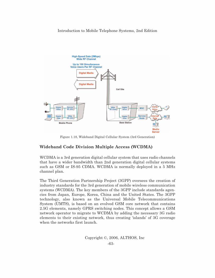
Wideband Code Division Multiple Access (WCDMA)
WCDMA is a 3rd generation digital cellular system that uses radio channelsthat have a wider bandwidth than 2nd generation digital cellular systemssuch as GSM or IS-95 CDMA. WCDMA is normally deployed in a 5 MHzchannel plan.
The Third Generation Partnership Project (3GPP) oversees the creation ofindustry standards for the 3rd generation of mobile wireless communicationsystems (WCDMA). The key members of the 3GPP include standards agen-cies from Japan, Europe, Korea, China and the United States. The 3GPPtechnology, also known as the Universal Mobile TelecommunicationsSystem (UMTS), is based on an evolved GSM core network that contains2.5G elements, namely GPRS switching nodes. This concept allows a GSMnetwork operator to migrate to WCDMA by adding the necessary 3G radioelements to their existing network, thus creating ‘islands’ of 3G coveragewhen the networks first launch.
-63-
Copyright ©, 2006, ALTHOS, Inc
Introduction to Mobile Telephone Systems, 2nd Edition
Figure 1.18, Wideband Digital Cellular System (3rd Generation)
Code Division Multiple Access 2000 (CDMA2000)
CDMA2000 is a family of standards that represent an evolution from the IS-95 code division multiple access (CDMA) system that offer enhanced packettransmission protocols to provide for advanced high-speed data services.The CDMA2000 technologies operate in the same 1.25 MHz radio channelsas used by IS-95 and offer backward compatibility with IS-95.
The CDMA2000 system is overseen by the Third Generation PartnershipProject 2 (3GPP2). The 3GPP2 is a standard setting project that is focusedon developing global specifications for 3rd generation systems that useANSI/TIA/EIA-41 Cellular Radio Intersystem Signaling.
Time Division Synchronous CDMA (TD-SCDMA)
On a global basis it is likely that WCDMA and CDMA2000™ will dominatethe 3G market. However, in China there is growing support for a home-grown standard known as Time Division Synchronous CDMA (TD-SCDMA).TD-SCDMA offers voice services and data services, both circuit-switchedand packet-switched, at rates up to 2 Mbps. It uses a Time Division Duplex(TDD) technique in which transmit and receive signals are sent on the samefrequency but at different times. The timeslots on the radio carrier caneither be allocated symmetrically for services such as speech or asymmetri-cally for data services where the bit rates in the two directions of transmis-sion may differ significantly.
Fourth Generation (4G) Networks
Fourth Generation wireless networks with bandwidth reaching 100 Mbpsthat allow for voice and data applications that will run 50 times faster than3G. This capacity will enable three dimensional (3D) renderings and othervirtual experiences on the mobile device.
-64-
Copyright ©, 2006, ALTHOS, Inc
Introduction to Mobile Telephone Systems, 2nd Edition
Even before 3G networks are fully launched and utilized, various studygroups are considering the shape of the next generation of cellular technol-ogy, so called 4G. There is no single global vision for 4G as yet but the nextgeneration of network is likely to be all IP-based, offering local (in building)data rates up to 1 Gbps, wide area data rates of 100 Mbps (rural) and sup-port global mobility. One route towards this vision is the convergence oftechnologies such as 3G cellular and Wireless LANs (WLANs).
Mobile Services
Mobile services are the providing of wireless data transmission and/or infor-mation processing services to customers by a mobile system service opera-tor. The services that mobile systems can provide include voice services,data services, multicast services, location-based services (LBS), and multi-media communication services that have various levels of quality of service(QoS).
Voice Services
Voice service is a type of communication service where two or more peoplecan transfer information in the voice frequency band (not necessarily voicesignals) through a communication network. Voice service involves the setupof communication sessions between two (or more) users that allows for thereal time (or near real time) transfer of voice type signals between users. Amobile system may offer several types of voice services including
The voice service quality on the mobile systems can vary based on a varietyof factors. Mobile systems may assign different levels of voice quality byusing different types of speech compression. The service provider can selectand control which speech compression process (voice coding) is used. Theselection of voice coders that have higher levels of speech compression (high-er compression results in less digital bits transmitted) allows the serviceprovider to increase the number of customers it can provide service to withthe tradeoff of providing lower quality audio signals.
-65-
Copyright ©, 2006, ALTHOS, Inc
Introduction to Mobile Telephone Systems, 2nd Edition
Circuit Switched Voice
Circuit switched voice service is a communication method that maintains adedicated communications path between two communication devicesregardless of the amount of information that is sent between the devices.This gives to communications equipment the exclusive use of the circuit thatconnects them, even when the circuit is momentarily idle.
Voice communication can be telephony; wide area (cellular), business loca-tion (wireless office), home cordless (residential), voice paging, dispatch(fleet coordination) or group voice (audio broadcasting). Service rates forvoice applications typically involve an initial connection charge, basicmonthly minimum fee, more likely a monthly access fee that includes somefree airtime minutes, and an airtime usage charge. When the customer usesservice in a system other than their home registered system (roaming),there may be a daily roaming fee and/or a higher per minute roaming usagefee.
Figure 1.19 shows a sample service rate plan for mobile telephone voice ser-vices. This example shows that there is usually a fee to activate service (con-nection charge), a recurring monthly charge ($29.95 per month), a bundledamount of peak and off-peak minutes (500 peak, 2000 off-peak), a fee forusage of airtime minutes in excess of the subscribed amount ($0.40 perminute), and a higher-usage fee when operating (roaming) in other systems($0.90). This rate plan also shows that advanced services may be offered forfree (to increase the number of minutes used).
-66-
Copyright ©, 2006, ALTHOS, Inc
Introduction to Mobile Telephone Systems, 2nd Edition
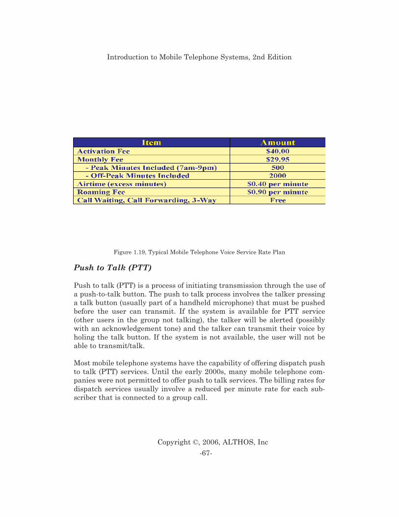
Push to Talk (PTT)
Push to talk (PTT) is a process of initiating transmission through the use ofa push-to-talk button. The push to talk process involves the talker pressinga talk button (usually part of a handheld microphone) that must be pushedbefore the user can transmit. If the system is available for PTT service(other users in the group not talking), the talker will be alerted (possiblywith an acknowledgement tone) and the talker can transmit their voice byholing the talk button. If the system is not available, the user will not beable to transmit/talk.
Most mobile telephone systems have the capability of offering dispatch pushto talk (PTT) services. Until the early 2000s, many mobile telephone com-panies were not permitted to offer push to talk services. The billing rates fordispatch services usually involve a reduced per minute rate for each sub-scriber that is connected to a group call.
-67-
Copyright ©, 2006, ALTHOS, Inc
Introduction to Mobile Telephone Systems, 2nd Edition
Figure 1.19, Typical Mobile Telephone Voice Service Rate Plan
Messaging
Messaging services for mobile telephones involve the sending or receiving ofshort messages. Messaging services are commonly limited to approximately160 characters per message. The cost of messaging service usually involvesa specific cost per message when the number of messages exceeds a certainnumber of messages.
Data Service
Data Services are communication services that transfer informationbetween two or more devices. Data services may be provided in or outsidethe audio frequency band through a separate data communication network.Data service involves the establishment of physical and logical communica-tion sessions between two (or more) users that allows for the non-real timeor near-real time transfer of data (binary) type signals between users.
When data signals are transmitted on a non-digital channel (such as an ana-log telephone line), a data modem must be used. The data modem convertsthe data signal (digital bits) into tones that can be transferred in the audiofrequency band. Because the speech coder used in the digital mobile systemssystem only compresses voice signals and not data modem signals, analogmodem data cannot be sent on a digital mobile telephone (voice) channel.
When data signals are transmitted on a digital radio channel, a data trans-fer adapter (DTA) is used. The DTA converts the data bits from a comput-ing device into a format that is suitable for transmission on a communica-tion channel that has a different data transmission format. DTAs are usedto connect communication devices (such as a PDA or laptop) to a mobiledevice when it is operating on a digital radio channel. The data service on
2nd and 3rd generation mobile systems can range from low-speed packetdata up to more than 2 Mbps. Data services may be offered as circuitswitched data (continuous connections) or packet switched data.
-68-
Copyright ©, 2006, ALTHOS, Inc
Introduction to Mobile Telephone Systems, 2nd Edition
When using circuit switched data, the user typically pays only for the air-
time used. Circuit switched data transfer rates on analog and 2nd genera-tion digital systems are usually limited to about 14.4 kbps. For continuousdata transmission of over 30 seconds, this results in a cost of less than 1 centper kilobyte of data transferred. For very short burst of data transmission,circuit switched data can cost over $1 per kilobyte ($1000 per megabyte) ofdata because the call setup time is much longer than the data transmissionand most cellular systems charge a minimum of 1 minute fee per call.
In 2006, a majority of the data services offered on mobile systems were pack-et data services. The service charges for packet data commonly include amonthly minimum charge and a usage fee that is based on the number ofpackets or the amount of kilobytes of user information that is transferred.The typical usage charge for packet data services ranged from approxi-mately 1 cent to 20 cents per megabyte.
Circuit Switched Data
Circuit switched data is a data communication method that maintains adedicated communications path between two communication devicesregardless of the amount of data that is sent between the devices. This givesto communications equipment the exclusive use of the circuit that connectsthem, even when the circuit is momentarily idle.
To establish a circuit-switched data connection, the address is sent first anda connection (possibly a virtual non-physical connection) path is established.After this path is setup, data is continually transferred using this path untilthe path is disconnected by request from the sender or receiver of data.
Packet Switched Data
Packet switch data is the transfer of information between two pointsthrough the division of the data into small packets. The packets are routed(switched) through the network and reconnected at the other end to recre-ate the original data. Each data packet contains the address of its destina-tion. This allows each packet to take a different route through the networkto reach its destination.
-69-
Copyright ©, 2006, ALTHOS, Inc
Introduction to Mobile Telephone Systems, 2nd Edition
Mobile packet-switched data service is an “always-on” type of service. Whenthe mobile device is initially turned on, it takes only a few seconds to obtainan IP address that is necessary to communicate with the network. Evenwhen the mobile device is inactive and placed in the dormant state, recon-nection is typically less than 1/2 a second.
Location Based Services (LBS)
Location based services are information or advertising services that varybased on the location of the user. Mobile system may be capable of using dif-ferent types of location information sources including the system itself orthrough the use of a global positioning system (GPS).
Multicast Services
Multicast service is a one-to-many media delivery process that sends a sin-gle message or information transmission that contains an address (code)that is designated for several devices (nodes) in a network. Devices mustcontain the matching code to successfully receive or decode the message.Mobile multicast services can include news services or media (digital audio)broadcasts.
Quality of Service (QoS)
Quality of service (QoS) is one or more measurements of desired perfor-mance and priorities of a communications system. QoS measures mayinclude service availability, maximum bit error rate (BER), minimum com-mitted bit rate (CBR) and other measurements that are used to ensure qual-ity communications service.
The later generation mobile systems (e.g. 3G) can offer different types ofquality of service (QoS) for different types of customers and their applica-
-70-
Copyright ©, 2006, ALTHOS, Inc
Introduction to Mobile Telephone Systems, 2nd Edition
tions. A key QoS attribute includes priority access for different types ofusers. For example, real time priority access typically applies to voice ser-vices and reliable data transfer is applied to interactive data services.
Conversation Class
Conversation class is the providing of communication service (typicallyvoice) through a network with minimal delay in two directions. While con-versation has stringent maximum time delay limits (typically tens of mil-liseconds), it is typically acceptable to loose some data during transmissiondue to errors or discarding packets during system over capacity.
Streaming Class
Streaming class is the delivering of audio or video signals through a networkby establishing and managing of a continuous flow (a stream) of informa-tion. Upon request of streaming class of service, a server system (informa-tion source) will deliver a stream of audio and/or video (usually compressed)to a client. The client will receive the data stream and (after a short buffer-ing delay) decode the audio and play it to a user. Internet audio streamingsystems are used for delivering audio from 2 kbps (for low-quality speech)up to hundreds of kbps (for audiophile-quality music).
Streaming class provides a continuous stream of information that is com-monly used for the delivery of audio and video content with minimal delay(e.g. real-time). Streaming signals are usually compressed and error pro-tected to allow the receiver to buffer, decompress, and time sequence infor-mation before it is displayed in its original format.
Interactive Class
Interactive class is the providing of data and control information through anetwork with minimal delays and with very few data errors. Interactiveclass allows a user or system to interact with a software application (typi-cally a web host) in near-real time (limited transmission delays). Interactiveclass allows the communication channel to be shared by other users during
-71-
Copyright ©, 2006, ALTHOS, Inc
Introduction to Mobile Telephone Systems, 2nd Edition
periods of inactivity such as when the user is thinking about a response toa web page question.
Background Class
Background class is the process of providing information transfer serviceson a best-effort basis. Background class is used for non-time critical services(such as Internet web browsing).
-72-
Copyright ©, 2006, ALTHOS, Inc
Introduction to Mobile Telephone Systems, 2nd Edition
References:
1 William Lee, “Mobile Cellular Telecommunications Systems”, p.2, McGrawHill, 1989.2 Personal interview, Industry expert, 2 September, 2003.3 William Lee, “Mobile Cellular Telecommunications Systems”, McGraw Hill,1989, p.5.4 William Lee, “Mobile Cellular Telecommunications Systems”, McGraw Hill,1989, p.265.5. Cellular Radio, Analog and Digital Systems, Mehrotra, Pg 177.6. Asha, K Mehrotra, “Cellular Radio: Analog and Digital Systems”, ArtechHouse, 1994,, pg 74.7. Asha, K Mehrotra, “Cellular Radio: Analog and Digital Systems”, ArtechHouse, 1994,, pg. 177.8. D. M. Balston (Editor), R.C.V. MacArio, “Cellular Radio Systems”, ArtechHouse, 1993, pg 77.9. Asha, K Mehrotra, “Cellular Radio: Analog and Digital Systems”, ArtechHouse, 1994, pg. 19310. Mehrotra, Cellular Radio, Analog and Digital Systems, Mehrotra, pg. 18611. Asha, K Mehrotra, “Cellular Radio: Analog and Digital Systems”, ArtechHouse, 1994,, pg. 188.12. Asha, K Mehrotra, “Cellular Radio: Analog and Digital Systems”, ArtechHouse, 1994,, pg. 193.13 “Digital Cellular, Economics and Comparative Technologies,” EMCI, May,1993, pg. 75.14 Lawrence Harte, “Cellular and PCS, The Big Picture,” McGraw-Hill, 1997,Pg. 130
-73-
Copyright ©, 2006, ALTHOS, Inc
Introduction to Mobile Telephone Systems, 2nd Edition
-74-
Copyright ©, 2006, ALTHOS, Inc
Introduction to Mobile Telephone Systems, 2nd Edition
1G-First Generation 1xEVDO-One Channel EvolutionVersion Data Only 1xEVDV-One Channel EvolutionVersion Data and Voice 2.5G-Second And A Half Generation 2G-Second Generation 3G-Third Generation 3GPP-3rd Generation PartnershipProject 3GPP2-3rd Generation PartnershipProject 2 4G-Fourth Generation 8-PSK-8 Level PSK AAA-Authentication, Authorization,Accounting ACC-Analog Control Channel AMPS-Advanced Mobile Phone Service AuC-Authentication Center BC-Billing Center BCH-Broadcast Channel BER-Bit Error Rate BS-Base Station BSC-Base Station Controller BTS-Base Transceiver Station CBR-Constant Bit Rate CDG-CDMA Development Group CDMA-Code Division Multiple Access CDMA2000-Code Division MultipleAccess 2000 CDR-Call Detail Record
CN-Core Network D/R-Distance to Reuse Ratio DAMPS-Digital Advance Mobile PhoneService DCC-Digital Color Code DTA-Data Transfer Adapter DTC-Digital Traffic Channel EDGE-Enhanced Data Rates ForGlobal Evolution EDI-Electronic Data Interchange EIR-Equipment Identity Register ESMR-Enhanced Specialized MobileRadio ETACS-Extended TACS ETDMA-Extended Time DivisionMultiple Access FDD-Frequency Division Duplex FDM-Frequency Division Multiplexing FDMA-Frequency Division MultipleAccess FM-Frequency Modulation FSK-Frequency Shift Keying GGSN-Gateway GPRS Support Node GMSC-Gateway Mobile SwitchingCenter GMSK-Gaussian Minimum ShiftKeying GPRS-General Packet Radio Service GPS-Global Positioning System GSM-Global System For MobileCommunications
-75-
Copyright ©, 2006, ALTHOS, Inc
Appendix 1
Acronyms
GSN-GPRS Support Node HLR-Home Location Register IC-Interchange Carrier iDEN-Integrated Dispatch EnhancedNetwork IMEI-International Mobile EquipmentIdentifier IMSI-International Mobile SubscriberIdentity ITU-International TelecommunicationUnion IWF-Interworking Function LBS-Location Based Services LMR-Land Mobile Radio MC-Message Center MC-Multicarrier Mode MCS-Mobile Cellular System ME-Mobile Equipment MIN-Mobile Identification Number MIRS-Motorola Integrated RadioSystem MSC-Mobile Station Class MSC-Mobile Switching Center MTS-Mobile Telephone Service NAMPS-Narrowband AdvancedMobile Phone Service NMT-Nordic Mobile Telephone NPDB-Number Portability Database NTACS-Narrowband Total AccessCommunication System PAD-Packet Assembler AndDisassembler PCM-Pulse Coded Modulation PCN-Personal CommunicationsNetwork PCS-Personal CommunicationServices PDA-Personal Digital Assistant PDC-Personal Digital Cellular PDSN-Packet Data Switched Network PM-Phase Modulation PM-Pulse Modulation
PN-Packet Number PN-Pseudo-Random NoisePPDN-Public Packet Data Network PSTN-Public Switched TelephoneNetwork PTT-Post, Telephone And Telegraph PTT-Push To Talk QoS-Quality Of Service RAN-Radio Access Network RNC-Radio Network Controller SCH-Synchronization Channel SDMA-Spatial Division MultipleAccess SGSN-Serving General Packet RadioService Support Node SIM-Subscriber Identity Module SIS-Subscriber Identity Security SMS-Short Message Service SMSC-Short Message Service Center TACS-Total Access CommunicationsSystem TCH-Traffic Channel TDD-Time Division Duplex TDMA-Time Division Multiple Access TD-SCDMA-Time DivisionSynchronous Code Division MultipleAccess TIA-Telecommunications IndustryAssociation UE-User Equipment UMTS-Universal MobileTelecommunications System UPR-User Performance Requirements USB-Universal Serial Bus VLR-Visitor Location Register VMS-Voice Mail System WCDMA-Wideband Code DivisionMultiple Access WLAN-Wireless Local Area Network
Introduction to Mobile Telephone Systems, 2nd Edition
-76-
Copyright ©, 2006, ALTHOS, Inc
2.5G, 59, 633rd Generation Partnership Project
(3GPP), 633rd Generation Partnership Project 2
(3GPP2), 648 Level PSK (8-PSK), 60Access Channel, 30Access Probe, 30-31Advanced Mobile Phone Service
(AMPS), 38-41, 43-44, 52-56Analog Control Channel (ACC), 54, 57Antenna, 4, 13, 20-21Audio Broadcasting, 66Authentication, 22, 24, 26, 31, 44, 48Authentication Center (AuC), 26Authentication Key (A-key), 71Authentication Procedure, 26Authentication, Authorization,Accounting (AAA), 22Bandwidth, 3, 7-8, 12, 34, 41-45, 48-49,
51, 53-54, 56-57, 60-64Base Station (BS), 1, 3, 6, 14, 19-21, 23,
32-38, 43, 45, 48, 50, 55Base Station Antenna, 21Base Station Controller (BSC), 20, 23Base Transceiver Station (BTS), 23, 32Battery, 38, 48Billing, 15, 24-26, 67Billing Center (BC), 26Bit Error Rate (BER), 70Bit Rate, 52, 54, 70Bits Per Second (bps), 41-42, 44-46, 48Blank and Burst, 36, 45, 48Blank and Burst Signaling, 45Blocking, 5Broadcast, 27-29, 36, 51Broadcast Channel (BCH), 29Call Processing, 2
Carrier, 8, 10-11, 22, 25, 31, 51-52, 54,57, 64
Carrier Frequency, 51, 54CDMA Development Group (CDG), 58CDMA2000, 60-62, 64Cell Site, 3, 5-6, 13, 20, 28, 42-43, 45-46Cell Splitting, 4-5Cellular System, 1-3, 5, 36-40, 42-48, 50-51, 53, 56-57, 59, 62-63
Cellular Telecommunications IndustryAssociation (CTIA), 52-53
Channel Coding, 48Channel Structure, 54Circuit Switched Data, 22, 68-69Code Division Multiple Access (CDMA),
9, 12, 46, 49, 51, 56-58, 62-64Code Division Multiple Access 2000
(CDMA2000), 60-62, 64Constant Bit Rate (CBR), 70Control Channel, 21, 27-30, 36-37,
40-42, 45-47, 53-54, 57Controller, 20, 23, 25Core Network (CN), 19, 58, 63Data Services, 14, 18-19, 56, 59-61,
64-65, 68-69, 71Data Transfer Adapter (DTA), 68Data Transmission, 2, 30, 33, 51, 60-62,
65, 68-69Decibel (dB), 40-41Dedicated Control Channel, 42, 45Digital Advance Mobile Phone Service
(DAMPS), 52-53Digital Color Code (DCC), 54, 57Digital Traffic Channel (DTC), 47, 50,
53, 57, 60Discontinuous Reception (DRx), 29, 42Discontinuous Transmission (DTx), 38,
48
-77-
Copyright ©, 2006, ALTHOS, Inc
Index
Dispatch, 21, 56, 66-67Diversity Reception, 45Dual Band, 53Dual Mode, 15, 18, 53, 57Dual-Tone Multifrequency (DTMF), 24Duplex, 35, 39-42, 45, 51, 64Electronic Data Interchange (EDI), 26Electronic Serial Number (ESN), 37, 44Enhanced Data Rates for GlobalEvolution (EDGE), 60Enhanced Specialized Mobile Radio
(ESMR), 56Equipment Identity Register (EIR),
24-26Error Detection, 42, 54Extended TACS (ETACS), 40-41Extended Time Division Multiple Access
(ETDMA), 54-55Facsimile Communications (FAX)Fading, 57First Generation (1G), 34Fourth Generation (4G), 64-65Frame, 11, 32, 56Fraud, 26Frequency Allocation, 10Frequency Bands, 39, 41, 44-45Frequency Division Duplex (FDD), 39Frequency Division Multiple Access
(FDMA), 9-10, 39, 56Frequency Division Multiplexing
(FDM), 10Frequency Modulation (FM), 34, 36, 38,
41, 43, 46, 49Frequency Planning, 57Frequency Reuse, 2-4Frequency Shift Keying (FSK), 8, 38-39Full Rate, 52, 54Gateway GPRS Support Node (GGSN),
19, 23Gateway Mobile Switching Center(GMSC), 19
General Packet Radio Service (GPRS), 14, 19, 23, 60, 63
Global Positioning System (GPS), 70Global System For Mobile
Communications (GSM), 4, 14, 40-42,49, 51-52, 58, 60-61, 63
GPRS Support Node (GSN), 14, 19, 23Handoff, 5-6, 38, 50Handover, 2, 5-6, 28, 32-33, 52Hertz (Hz), 48Home Location Register (HLR), 24-25Integrated Dispatch Enhanced Network
(iDEN), 56Interchange Carrier (IC), 45Interconnection, 19, 38, 50Interference, 3-4, 21, 54Interleaving, 44-45International Mobile EquipmentIdentity (IMEI), 25International Mobile SubscriberIdentity (IMSI), 25International TelecommunicationsUnion (ITU), 62Internet Protocol Address (IP Address),
32-33, 70Internet Protocol Telephony
(IP Telephony), 33Intersystem Signaling, 64Interworking Function (IWF), 22IS-136 (US TDMA), 49, 51-55, 58IS-54 (TDMA), 52-53, 55IS-88 (NAMPS), 44IS-95 (CDMA), 56-58, 61-64Land Mobile Radio (LMR), 21Line of Sight (LOS), 3Location Based Services (LBS), 65, 70Message Center (MC), 23Mobile Cellular System (MCS), 38, 44Mobile Equipment (ME), 19, 25Mobile Identification Number (MIN), 37Mobile Station (MS), 36-37
Introduction to Mobile Telephone Systems, 2nd Edition
-78-
Copyright ©, 2006, ALTHOS, Inc
Mobile Station Class (MSC), 1-2, 5-6, 14,19-20, 22-23, 25, 38, 49-50, 62
Mobile Switching Center (MSC), 1-2, 5-6, 14, 19-20, 22-23, 25, 38, 49-50, 62
Mobile Telephone Service (MTS), 1Mobile Telephone, 1-74Modems, 15, 17-18Modulation, 2, 8-9, 34, 36, 38, 41, 44,
46-50, 53, 60-61Motorola Integrated Radio System
(MIRS), 56Multicarrier Mode (MC), 23Multiple Access, 9-13, 39, 51, 56, 62-64Multiplexing, 9-10Narrowband Advanced Mobile Phone
Service (NAMPS), 43-44Narrowband Total Access
Communication System (NTACS), 41,44
Nordic Mobile Telephone (NMT), 38, 41-43
Number Portability Database (NPDB),26
One Channel Evolution Version Data and Voice (1xEVDV), 61-62
One Channel Evolution Version DataOnly (1xEVDO), 61
Packet Assembler and Disassembler(PAD), 14
Packet Data, 2, 6, 14, 19, 23-24, 33, 59-62, 68-69
Packet Data Serving Node (PDSN), 19Packet Data Switched Network (PDSN),
19Packet Number (PN), 57-58Paging, 21, 28-30, 32, 35-37, 47-48, 51,
54, 57, 66Paging Channel, 32Paging Group, 32Personal Communication Services
(PCS), 1, 35, 51, 53, 73
Personal Communications Network(PCN), 51
Personal Communications Services(PCS), 1, 35, 51, 53, 73
Personal Digital Assistant (PDA), 68Personal Digital Cellular (PDC), 58Phase Modulation (PM), 8, 47, 60Pilot Channel, 29Point to Point Microwave (PTP), 21Post, Telephone and Telegraph (PTT),
67Power Control, 33Power Level, 4, 28, 30-32, 34, 38, 41-42,
48, 54, 58Propagation, 3Pseudo-Random Noise(PN), 57-58Public Packet Data Network (PPDN), 24Public Switched Telephone Network
(PSTN), 1, 19, 22, 24, 48Pulse Coded Modulation (PCM), 7Pulse Modulation (PM), 47Push To Talk (PTT), 67Quadrature Amplitude Modulation
(QAM), 8Quality of Service (QoS), 65, 70-71Radio Access Network (RAN), 14, 19Radio Carrier, 51, 57, 64Radio Channel, 1, 3-4, 10-12, 14, 18, 21,
27, 29, 33-35, 39-42, 44, 46-47, 49-62,68
Radio Coverage, 5, 13, 28, 34Radio Network Controller (RNC), 23Receiver, 20, 29, 36, 38, 55, 69, 71Registration, 29, 34Roaming, 62, 66Second And A Half Generation (2.5G),
59, 63Second Generation (2G), 18, 51, 59Sector, 13Serving General Packet Radio ServiceSupport Node (SGSN), 19, 23
Index
-79-
Copyright ©, 2006, ALTHOS, Inc
Short Message Service (SMS), 23, 53-54Short Message Service Center (SMSC),
19Signaling Channel, 41Simulcast, 44Single Mode, 18Sleep Mode, 29, 51, 54, 57Soft Capacity, 58Spatial Division Multiple Access
(SDMA), 9, 13Specialized Mobile Radio (SMR), 56Speech Activity, 49Speech Coder, 7, 49-50, 54, 68Speech Coding, 7, 49, 58Spread Spectrum, 56Standards, 56, 63-64Subscriber Identity Module (SIM),
15-16, 19, 29Subscriber Identity Security (SIS), 43Synchronization Channel (SCH), 29System Identification (SID), 29, 36, 40,
47Telecommunications Industry
Association (TIA), 52, 64Third Generation (3G), 1, 18, 59, 61,
63-65, 70Time Delay, 71Time Division Duplex (TDD), 64Time Division Multiple Access (TDMA),
4, 9, 11, 46, 49, 51-56, 58Time Division Synchronous CodeDivision Multiple Access (TD-SCDMA),64
Time Slot, 11, 47, 52-55Total Access Communications System
(TACS), 38, 40-42Traffic Channel (TCH), 47, 50, 53, 57, 60Transceiver, 11, 14, 20-21, 23, 32Transmit Power, 41Universal Mobile Telecommunications
System (UMTS), 63Universal Serial Bus (USB), 17
User Equipment (UE), 19User Performance Requirements (UPR),
52-53Variable Rate Speech Coding, 58Visitor Location Register (VLR), 23-25Voice Channel, 21, 36-37, 40-42, 47-49,
57, 68Voice Coding, 7, 49, 58, 65Voice Mail System (VMS), 24Voice Message System (VMS), 24Voice Paging, 66Voice Services, 60, 64-66, 71Wideband, 57, 62-63Wideband Code Division Multiple
Access (WCDMA), 17, 23, 62-64
Introduction to Mobile Telephone Systems, 2nd Edition
-80-
Copyright ©, 2006, ALTHOS, Inc
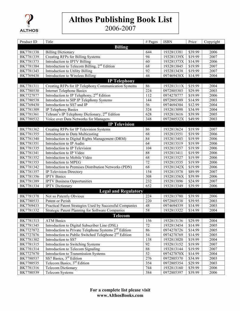
For a complete list please visitwww.AlthosBooks.com
Althos Publishing Book List2006-2007
Product ID Title # Pages ISBN Price CopyrightBilling
BK7781338 Billing Dictionary 644 1932813381 $39.99 2006BK7781339 Creating RFPs for Billing Systems 94 193281339X $19.99 2007BK7781373 Introduction to IPTV Billing 60 193281373X $14.99 2006BK7781384 Introduction to Telecom Billing, 2nd Edition 68 1932813845 $19.99 2007BK7781343 Introduction to Utility Billing 92 1932813438 $19.99 2007BK7769438 Introduction to Wireless Billing 44 097469438X $14.99 2004
IP TelephonyBK7781311 Creating RFPs for IP Telephony Communication Systems 86 193281311X $19.99 2004BK7780530 Internet Telephone Basics 224 0972805303 $29.99 2003BK7727877 Introduction to IP Telephony, 2nd Edition 112 0974278777 $19.99 2006BK7780538 Introduction to SIP IP Telephony Systems 144 0972805389 $14.99 2003BK7769430 Introduction to SS7 and IP 56 0974694304 $12.99 2004BK7781309 IP Telephony Basics 324 1932813098 $34.99 2004BK7781361 Tehrani’s IP Telephony Dictionary, 2nd Edition 628 1932813616 $39.99 2005BK7780532 Voice over Data Networks for Managers 348 097280532X $49.99 2003
IP TelevisionBK7781362 Creating RFPs for IP Television Systems 86 1932813624 $19.99 2007BK7781355 Introduction to Data Multicasting 68 1932813551 $19.99 2006BK7781340 Introduction to Digital Rights Management (DRM) 84 1932813403 $19.99 2006BK7781351 Introduction to IP Audio 64 1932813519 $19.99 2006BK7781335 Introduction to IP Television 104 1932813357 $19.99 2006BK7781341 Introduction to IP Video 88 1932813411 $19.99 2006BK7781352 Introduction to Mobile Video 68 1932813527 $19.99 2006BK7781353 Introduction to MPEG 72 1932813535 $19.99 2006BK7781342 Introduction to Premises Distribution Networks (PDN) 68 193281342X $19.99 2006BK7781357 IP Television Directory 154 1932813578 $89.99 2007BK7781356 IPTV Basics 308 193281356X $39.99 2006BK7781389 IPTV Business Opportunities 232 1932813896 $24.99 2007BK7781334 IPTV Dictionary 652 1932813349 $39.99 2006
Legal and RegulatoryBK7781378 Not so Patently Obvious 224 1932813780 $39.99 2006BK7780533 Patent or Perish 220 0972805338 $39.95 2003BK7769433 Practical Patent Strategies Used by Successful Companies 48 0974694339 $14.99 2003BK7781332 Strategic Patent Planning for Software Companies 58 1932813322 $14.99 2004
TelecomBK7781313 ATM Basics 156 1932813136 $29.99 2004BK7781345 Introduction to Digital Subscriber Line (DSL) 72 1932813454 $14.99 2005BK7727872 Introduction to Private Telephone Systems 2nd Edition 86 0974278726 $14.99 2005BK7727876 Introduction to Public Switched Telephone 2nd Edition 54 0974278769 $14.99 2005BK7781302 Introduction to SS7 138 1932813020 $19.99 2004BK7781315 Introduction to Switching Systems 92 1932813152 $19.99 2007BK7781314 Introduction to Telecom Signaling 88 1932813144 $19.99 2007BK7727870 Introduction to Transmission Systems 52 097427870X $14.99 2004BK7780537 SS7 Basics, 3rd Edition 276 0972805370 $34.99 2003BK7780535 Telecom Basics, 3rd Edition 354 0972805354 $29.99 2003BK7781316 Telecom Dictionary 744 1932813160 $39.99 2006BK7780539 Telecom Systems 384 0972805397 $39.99 2006
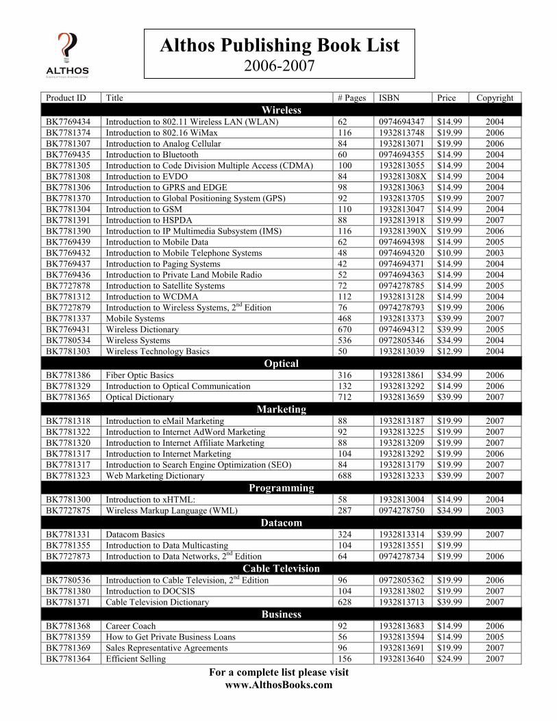
For a complete list please visitwww.AlthosBooks.com
Althos Publishing Book List2006-2007
Product ID Title # Pages ISBN Price CopyrightWireless
BK7769434 Introduction to 802.11 Wireless LAN (WLAN) 62 0974694347 $14.99 2004BK7781374 Introduction to 802.16 WiMax 116 1932813748 $19.99 2006BK7781307 Introduction to Analog Cellular 84 1932813071 $19.99 2006BK7769435 Introduction to Bluetooth 60 0974694355 $14.99 2004BK7781305 Introduction to Code Division Multiple Access (CDMA) 100 1932813055 $14.99 2004BK7781308 Introduction to EVDO 84 193281308X $14.99 2004BK7781306 Introduction to GPRS and EDGE 98 1932813063 $14.99 2004BK7781370 Introduction to Global Positioning System (GPS) 92 1932813705 $19.99 2007BK7781304 Introduction to GSM 110 1932813047 $14.99 2004BK7781391 Introduction to HSPDA 88 1932813918 $19.99 2007BK7781390 Introduction to IP Multimedia Subsystem (IMS) 116 193281390X $19.99 2006BK7769439 Introduction to Mobile Data 62 0974694398 $14.99 2005BK7769432 Introduction to Mobile Telephone Systems 48 0974694320 $10.99 2003BK7769437 Introduction to Paging Systems 42 0974694371 $14.99 2004BK7769436 Introduction to Private Land Mobile Radio 52 0974694363 $14.99 2004BK7727878 Introduction to Satellite Systems 72 0974278785 $14.99 2005BK7781312 Introduction to WCDMA 112 1932813128 $14.99 2004BK7727879 Introduction to Wireless Systems, 2nd Edition 76 0974278793 $19.99 2006BK7781337 Mobile Systems 468 1932813373 $39.99 2007BK7769431 Wireless Dictionary 670 0974694312 $39.99 2005BK7780534 Wireless Systems 536 0972805346 $34.99 2004BK7781303 Wireless Technology Basics 50 1932813039 $12.99 2004
OpticalBK7781386 Fiber Optic Basics 316 1932813861 $34.99 2006BK7781329 Introduction to Optical Communication 132 1932813292 $14.99 2006BK7781365 Optical Dictionary 712 1932813659 $39.99 2007
MarketingBK7781318 Introduction to eMail Marketing 88 1932813187 $19.99 2007BK7781322 Introduction to Internet AdWord Marketing 92 1932813225 $19.99 2007BK7781320 Introduction to Internet Affiliate Marketing 88 1932813209 $19.99 2007BK7781317 Introduction to Internet Marketing 104 1932813292 $19.99 2006BK7781317 Introduction to Search Engine Optimization (SEO) 84 1932813179 $19.99 2007BK7781323 Web Marketing Dictionary 688 1932813233 $39.99 2007
ProgrammingBK7781300 Introduction to xHTML: 58 1932813004 $14.99 2004BK7727875 Wireless Markup Language (WML) 287 0974278750 $34.99 2003
DatacomBK7781331 Datacom Basics 324 1932813314 $39.99 2007BK7781355 Introduction to Data Multicasting 104 1932813551 $19.99BK7727873 Introduction to Data Networks, 2nd Edition 64 0974278734 $19.99 2006
Cable TelevisionBK7780536 Introduction to Cable Television, 2nd Edition 96 0972805362 $19.99 2006BK7781380 Introduction to DOCSIS 104 1932813802 $19.99 2007BK7781371 Cable Television Dictionary 628 1932813713 $39.99 2007
BusinessBK7781368 Career Coach 92 1932813683 $14.99 2006BK7781359 How to Get Private Business Loans 56 1932813594 $14.99 2005BK7781369 Sales Representative Agreements 96 1932813691 $19.99 2007BK7781364 Efficient Selling 156 1932813640 $24.99 2007
For a complete list please visitwww.AlthosBooks.com
Althos Publishing Book List2006-2007
Order FormPhone: 1 919-557-2260Fax: 1 919-557-2261 Date:______________404 Wake Chapel Rd., Fuquay-Varina, NC 27526 USA
Name:______________________________________ Title:__________________________________Company:____________________________________________________________________________Shipping Address:_____________________________________________________________________City:____________________________________ State:_______________ Postal/ Zip:_______________Billing Address:_______________________________________________________________________City:____________________________________ State:_______________ Postal/ Zip _______________Telephone:_______________________________ Fax:________________________________________Email: _______________________________________________________________________________________Payment (select): VISA ___ AMEX ___ MC ___ Check ____Credit Card #: ________________________________________Expiration Date: ___________________Exact Name on Card: _______________________________________
Qty. Product ID ISBN Title Price Ea Total
Book Total:Sales Tax (North Carolina Residents please add 7% sales tax)Shipping: $5 per book in the USA, $10 per book outside USA (most countries). Lower shipping and rates maybe available online.
Total order:

For a complete list please visitwww.AlthosBooks.com
Althos Publishing Book List2006-2007