INTRODUCTION TO ETHERNET/IP™ Technical Reference ... · EtherNet/IP was first presented in March...
43
INTRODUCTION TO ETHERNET/IP™ Technical Reference – EtherNet/IP™ BusWorks® 9xxEN-6xxx Series BusWorks® XT1xx2-000 Series 10/100MB Industrial Ethernet I/O Modules Tel: (248) 295-0880 Fax: (248) 624-9234 email: [email protected] ACROMAG INCORPORATED 30765 South Wixom Road Wixom, MI 48393 U.S.A. Copyright, Acromag, Inc., Printed in the USA. Data and specifications are subject to change without notice. 8500-747C
Transcript of INTRODUCTION TO ETHERNET/IP™ Technical Reference ... · EtherNet/IP was first presented in March...
INTRODUCTION TO ETHERNET/IP™
Technical Reference – EtherNet/IP™
BusWorks® 9xxEN-6xxx Series BusWorks® XT1xx2-000 Series 10/100MB Industrial Ethernet I/O Modules
Tel: (248) 295-0880 Fax: (248) 624-9234
email: [email protected]
ACROMAG INCORPORATED 30765 South Wixom Road Wixom, MI 48393 U.S.A.
Copyright, Acromag, Inc., Printed in the USA.
Data and specifications are subject to change without notice. 8500-747C
Introduction To EtherNet/IP™ BusWorks® Ethernet I/O
Acromag, Inc. Tel: 248-295-0880 - 2 - http://www.acromag.com - 2 - http://www.acromag.com
Table of Contents
INTRODUCTION TO ETHERNET/IP ABOUT ETHERNET/IP ....................................................................................... 3
Why Ethernet/IP .................................................................................................................. 3
About Determinism ............................................................................................................. 4
THE OSI NETWORK MODEL ............................................................................. 6The OSI 7-Layer Model ......................................................................................................... 8
TCP/IP Stack ........................................................................................................................ 9
Key Concepts & Terminology ............................................................................................. 11
APPLICATION LAYER ...................................................................................... 12Object-Oriented Terminology ............................................................................................ 12
CIP™ – Control & Information Protocol .............................................................................. 13
CIP™ Encapsulation Message ............................................................................................. 19
Connection Manager ......................................................................................................... 21
TRANSPORT LAYER ........................................................................................ 24TCP- Transport Control Protocol ......................................................................................... 24
TCP Example ...................................................................................................................... 27
UDP – User Datagram Protocol .......................................................................................... 28
NETWORK LAYER ............................................................................................ 30IP - Internet Protocol ......................................................................................................... 30
Ethernet (MAC) Address .................................................................................................... 32
Internet (IP) Address .......................................................................................................... 33
ARP – Address Resolution Protocol .................................................................................... 35
RARP – Reverse Address Resolution Protocol ..................................................................... 36
DATA LINK LAYER ........................................................................................... 37CSMA/CD – Carrier Sense Multiple Access w/CD ................................................................ 38
MAC - Medium Access Control (MAC) Protocol ................................................................... 38
Ethernet (MAC) Packet....................................................................................................... 38
EDS (ELECTRONIC DATA SHEET) FILE ...................................................... 40Sample EDS File (983ENEIP.EDS) ......................................................................................... 41
All trademarks are the property of their respective owners. Windows® is a registered trademark of Microsoft Corporation. Modbus® is a registered trademark of Modicon, Incorporated. The following is a trademark under license by ODVA: EtherNet/IP™.
This information is provided as a service to our customers and to others interested in learning more about EtherNet/IP. Acromag assumes no responsibility for any errors that may occur in this document, and makes no commitment to update, or keep this information current. Be sure to visit Acromag on the web at www.acromag.com.
Introduction To EtherNet/IP™
BusWorks® Ethernet I/O
Acromag, Inc. Tel: 248-295-0880 - 3 - http://www.acromag.com - 3 - http://www.acromag.com
GETTING STARTED WITH ETHERNET/IP
ABOUT ETHERNET/IP
The following information describes the operation of EtherNet/IP as it relates to Acromag Series 900EN-60xx and XTxxx2-xxx I/O modules. To download a copy of the EtherNet/IP standard, you may refer to the Open DeviceNet Vendor Association (ODVA) web site for EtherNet/IP at www.ethernet-ip.org. Acromag also manufactures a line of I/O modules that support Modbus TCP/IP and EtherNet/IP. Feel free to visit our website at www.acromag.com to obtain the latest information about these and other Acromag products. EtherNet/IP was first presented in March of 2000 and is the result of a joint effort between ControlNet International (CI), the Open DeviceNet Vendor Association (ODVA), and the Industrial Ethernet Association (IEA), to produce a network protocol that addresses the high demand for using the widely popular Ethernet network in control applications. In a nutshell, EtherNet/IP (Ethernet Industrial Protocol) is traditional Ethernet combined with an industrial application layer protocol targeted to industrial automation. This application layer protocol is the Control and Information Protocol (CIP™).
Why Ethernet/IP EtherNet/IP™ (Ethernet Industrial Protocol) is traditional Ethernet combined with an industrial application layer protocol targeted to industrial automation. This application layer protocol is the Control and Information Protocol (CIP™).
IEEE 802.3 Ethernet is traditionally an office networking protocol that has gained universal acceptance world-wide. It is an open standard supported by many manufacturers and its infrastructure equipment is widely available and largely installed. Likewise, its TCP/IP suite of protocols is found everywhere and also serves as the foundation for access to the World Wide Web. Since many devices already support Ethernet I/O, it is only natural to augment it for use in industrial applications. As such, EtherNet/IP was created in an attempt to overcome the shortcomings of traditional IEEE 802.3 Ethernet as applied to the industrial automation world. For many years, the Control and Information Protocol (CIP™) has been widely used in industrial environments. CIP™ provides both real-time and informational message structures, and is designed to be “wire-independent” in that it can work with any data-link and physical layer. As CIP™ is freely available, accessible to anyone, easy to understand, and widely supported by many manufacturers of industrial equipment, it is a natural candidate for use in building other industrial communication standards. CIP™ was first adopted by DeviceNet in 1994, which merged the popular CAN protocol with CIP™ to form DeviceNet. ControlNet was the next protocol to adopt CIP™ in 1997. ControlNet is considered more deterministic and offered higher speeds (up to 5MB) than DeviceNet, plus it extending the range of the bus up to several kilometers with the use of repeaters.
Introduction To EtherNet/IP™ BusWorks® Ethernet I/O
Acromag, Inc. Tel: 248-295-0880 - 4 - http://www.acromag.com - 4 - http://www.acromag.com
Why Ethernet/IP?… Next, EtherNet/IP merged traditional IEEE 802.3 Ethernet with the Control and Information Protocol (CIP™) as its application layer to build an even more powerful industrial communication standard. EtherNet/IP shares the same physical and data link layers of traditional IEEE 802.3 Ethernet and uses the same TCP/IP suite of protocols. This makes it fully compatible with existing Ethernet hardware, such as cables, connectors, network interface cards, hubs, and switches. Since EtherNet/IP uses the same application layer protocol used by both DeviceNet and ControlNet, this allows these protocols to share common device profiles and object libraries, and also helps to make these types of devices interoperable on the same network.
EtherNet/IP is considered an open network standard for these reasons:
Its physical and data link layers use standard IEEE 802.3 Ethernet.
Its network layer uses the TCP/IP suite of protocols.
It is supported by four independent networking organizations – ControlNetInternational (CI), the Industrial Ethernet Organization (IEA), the OpenDeviceNet Vendor Association (ODVA), and the Industrial AutomationOpen Network Alliance (IAONA).
EtherNet/IP technology is also available free of charge to developers andvendors. The EtherNet/IP standard can also be downloaded free of chargefrom the ODVA web site.
About Determinism
Historically, traditional Ethernet was not considered a viable fieldbus for industrial control and I/O networks because of two major shortcomings: inherent non-determinism, and low durability. However, new technology properly applied has mostly resolved these issues.
Originally, Ethernet equipment was designed for the office environment, not harsh industrial settings. Although, many factory Ethernet installations can use this standard hardware without a problem, new industrial-rated connectors, shielded cables, and hardened switches and hubs are now available to help resolve the durability issue.
With respect to the non-deterministic behavior of Ethernet, understand that determinism is a term that is used here to describe the ability of a network protocol to guaranty that a packet is sent or received in a finite and predictable amount of time. Thus, for critical control applications, determinism is very important.
The arbitration protocol for carrier transmission access on any Ethernet network is called Carrier Sense Multiple Access with Collision Detect (CSMA/CD). Since any network device can try to send a data frame at any time, with CSMA/CD applied, each device will first sense whether the line is idle and available for use. If the line is available, the device will then begin to transmit its first frame. If another device also tries to send a frame at approximately the same time, then a collision occurs and both frames will be discarded.

Introduction To EtherNet/IP™
BusWorks® Ethernet I/O
Acromag, Inc. Tel: 248-295-0880 - 5 - http://www.acromag.com - 5 - http://www.acromag.com
About Determinism… Each device then waits a random amount of time and retries its transmission until its frame is successfully sent. This channel-allocation method is inherently non-deterministic because a device may only transmit when the wire is free, resulting in unpredictable wait times before data may be transmitted. Additionally, because of cable signaling delay, collisions are still possible once the device begins to transmit the data, thus forcing additional retransmission/retry cycles. As most control systems have a defined time requirement for packet transmission, typically less than 100ms, the potential for collisions and the CSMA/CD method of retransmission is not considered deterministic behavior. This is the reason that traditional Ethernet has had problems being accepted for use in critical control applications. However, Ethernet can be made more deterministic through the use of fast Ethernet switches, which increase the bandwidth of a large network by sub-dividing it into several smaller networks or “collision domains”. The switch also provides a direct connection from the sender to the receiver such that only the receiver receives the data, not the entire network. A switch (or switching hub) is an intelligent network device used to more efficiently connect distributed Ethernet nodes. Each port of a switch forwards data to another port based on the MAC address contained in the received data packet/frame. The switch will actually learn and store the MAC addresses of every device it is connected to, along with the associated port number. The port of a switch does not require its own MAC address and during retransmission of a received packet, the switch port will instead look like the originating device by having assumed its source address. In this way, the Ethernet collision domain is said to terminate at the switch port, and the switch effectively breaks the network into separate distinct data links or collision domains, one at each switch port. The ability of the switch to target a packet to a specific port, rather than forwarding it to all switch ports, also helps to eliminate the collisions that make Ethernet non-deterministic. Further, as switches have become less expensive, the current tendency in critical industrial control applications is to connect one Ethernet device per switch port, effectively treating the switch device as the hub of a star network. In this manner, with only one network device connected per switch port, the switch can run full-duplex, with no chance of collisions. Thus, a 10/100 Ethernet switch effectively runs at 20/200 Mbps because it can transmit and receive at 10 or 100 Mbps simultaneously (full duplex). Since there is only one device connected to a port, there is no chance of collisions occurring. The higher transfer speed of full-duplex coupled without the need for invoking CSMA/CD produces a more deterministic mode of operation, helping critical control applications to remain predictable and on-time. Unfortunately, broadcast traffic on a company network cannot be completely filtered by switches, and this may cause additional collisions reducing the determinism of a network connecting more than one device to a switch port. However, if the company network and the control & I/O network are instead separated, no traffic is added to the control network and its determinism is increased. Further, if a bridge is used to separate the two networks, then the bridge can usually be configured to filter unnecessary traffic.
Introduction To EtherNet/IP™ BusWorks® Ethernet I/O
Acromag, Inc. Tel: 248-295-0880 - 6 - http://www.acromag.com - 6 - http://www.acromag.com
About Determinism… Combining good network design with fast switches and bridges where necessary raises the determinism of a network, making EtherNet/IP more appealing. Other advances in Ethernet switches, such as, higher speeds, broadcast storm protection, virtual LAN support, SNMP, and priority messaging further help to increase the determinism of Ethernet networks. As Gigabit (Gbit), 10Gbit, and 100Gbit Ethernet enters the market, determinism will no longer be a concern.
With Ethernet as an open standard, numerous hardware and software vendors compete, resulting in low-cost, off-the-shelf products. As almost everyone knows what Ethernet is, it’s also easier and more efficient to train people on Ethernet than other networks. Currently, the research funding for Ethernet far surpasses that of any other fieldbus, further enabling faster development and increasingly higher speeds.
THE OSI NETWORK MODEL
The OSI Model represents the basic network architecture.
Each layer of this model uses the services provided by the layer immediately below it.
TCP/IP has no specific mappings to layers 5 and 6 of this model and these layers are often omitted when referring to the TCP/IP stack.
In order to better understand how EtherNet/IP is structured and the meaning of the term “open standard”, we need to review the Open Systems Interconnect (OSI) Reference Model. This model was developed by the International Standards Organization and adopted in 1983 as a common reference for the development of data communication standards. It does not attempt to define an implementation, but rather it serves as a structural aide to understanding “what must be done” and “what goes where”.
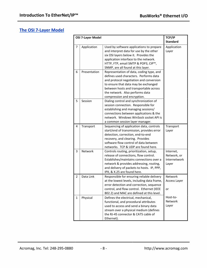
The traditional OSI model is presented in the table of the following page, along with the simplified 5-layer TCP/IP Standard (layers 5 & 6 suppressed). In the OSI model, the functions of communication are divided into seven (or five) layers, with every layer handling precisely defined tasks. For example, Layer 1 of this model is the physical layer and defines the physical transmission characteristics. Layer 2 is the data link layer and defines the bus access protocol. Layer 7 is the application layer and defines the application functions (this is the layer that defines how device data is to be interpreted). By the OSI Model, we can infer that in order for two devices to be interoperable on the same network, they must have the same application-layer protocol. In the past, many network devices have used their own proprietary protocols and this has hindered their interoperability. This fact further drove the need for adoption of an open network I/O solution that would allow devices from a variety of vendors to seamlessly work together, and this drive for interoperability is a key reason EtherNet/IP was created.
Note that in the TCP/IP Standard Model, Ethernet handles the bottom 2 layers (1 & 2) of the seven layer OSI stack, while TCP/IP handles the next two layers (3 & 4).The application layer lies above TCP, IP, and Ethernet and is the layer of informationthat gives meaning to the transmitted data.
With Acromag 9xxEN-40xx Modbus TCP/IP modules, the application layer protocol is Modbus. That is, Modbus TCP/IP uses Ethernet media and TCP/IP to communicate using an application layer with the same register access method as Modbus RTU. Because many manufacturers happen to support Modbus RTU and TCP/IP, and since Modbus is also widely understood and freely distributed, Modbus TCP/IP is also considered an open standard.
Introduction To EtherNet/IP™
BusWorks® Ethernet I/O
Acromag, Inc. Tel: 248-295-0880 - 7 - http://www.acromag.com - 7 - http://www.acromag.com
THE OSI NETWORK MODEL…
Although the Acromag 9xxEN-60xx modules are designed for EtherNet/IP, they also provide support for one additional socket of Modbus TCP/IP. With Acromag 9xxEN-60xx EtherNet/IP and XTxxx2-xxx modules, the application layer protocol is the Control and Information Protocol (CIP™). This is the same application layer protocol used by ControlNet and DeviceNet devices. By sharing the same application layer, these devices can be made interoperable on the same network. EtherNet/IP is based on the TCP/IP protocol family and shares the same lower four layers of the OSI model common to all Ethernet devices. This makes it fully compatible with existing Ethernet hardware, such as cables, connectors, network interface cards, hubs, and switches. However, EtherNet/IP adds the Control and Information Protocol (CIP™) as its application layer. This same application layer protocol is also used by both DeviceNet and ControlNet devices. This makes each of these device types interoperable on the same network and also allows these protocols to share common device profiles and object libraries.
Introduction To EtherNet/IP™
BusWorks® Ethernet I/O
Acromag, Inc. Tel: 248-295-0880 - 8 - http://www.acromag.com - 8 - http://www.acromag.com
The OSI 7-Layer Model
OSI 7-Layer Model TCP/IP
Standard
7 Application Used by software applications to prepare and interpret data for use by the other six OSI layers below it. Provides the application interface to the network. HTTP, FTP, email SMTP & POP3, CIP™, SNMP, are all found at this layer.
Application Layer
6 Presentation Representation of data, coding type, and defines used characters. Performs data and protocol negotiation and conversion to ensure that data may be exchanged between hosts and transportable across the network. Also performs data compression and encryption.
5 Session Dialing control and synchronization of session connection. Responsible for establishing and managing sessions/ connections between applications & the network. Windows WinSock socket API is a common session layer manager.
4 Transport Sequencing of application data, controls start/end of transmission, provides error detection, correction, end-to-end recovery, and clearing. Provides software flow control of data between networks. TCP & UDP are found here.
Transport Layer
3 Network Controls routing, prioritization, setup, release of connections, flow control. Establishes/maintains connections over a network & provides addressing, routing, and delivery of packets to hosts. IP, PPP, IPX, & X.25 are found here.
Internet, Network, or Internetwork Layer
2 Data Link Responsible for ensuring reliable delivery at the lowest levels, including data frame, error detection and correction, sequence control, and flow control. Ethernet (IEEE 802.2) and MAC are defined at this level.
Network Access Layer or Host-to-Network Layer
1 Physical Defines the electrical, mechanical, functional, and procedural attributes used to access and send a binary data stream over a physical medium (defines the RJ-45 connector & CAT5 cable of Ethernet).
Introduction To EtherNet/IP™
BusWorks® Ethernet I/O
Acromag, Inc. Tel: 248-295-0880 - 9 - http://www.acromag.com - 9 - http://www.acromag.com
TCP/IP Stack
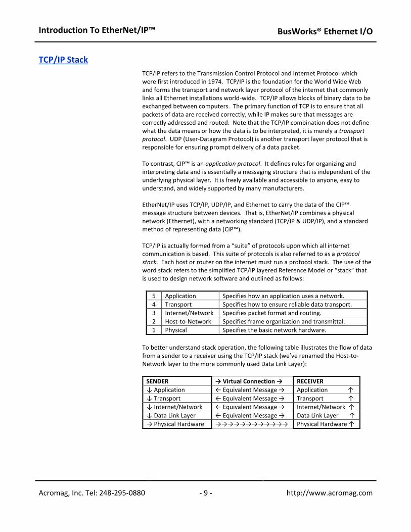
TCP/IP refers to the Transmission Control Protocol and Internet Protocol which were first introduced in 1974. TCP/IP is the foundation for the World Wide Web and forms the transport and network layer protocol of the internet that commonly links all Ethernet installations world-wide. TCP/IP allows blocks of binary data to be exchanged between computers. The primary function of TCP is to ensure that all packets of data are received correctly, while IP makes sure that messages are correctly addressed and routed. Note that the TCP/IP combination does not define what the data means or how the data is to be interpreted, it is merely a transport protocol. UDP (User-Datagram Protocol) is another transport layer protocol that is responsible for ensuring prompt delivery of a data packet. To contrast, CIP™ is an application protocol. It defines rules for organizing and interpreting data and is essentially a messaging structure that is independent of the underlying physical layer. It is freely available and accessible to anyone, easy to understand, and widely supported by many manufacturers. EtherNet/IP uses TCP/IP, UDP/IP, and Ethernet to carry the data of the CIP™ message structure between devices. That is, EtherNet/IP combines a physical network (Ethernet), with a networking standard (TCP/IP & UDP/IP), and a standard method of representing data (CIP™). TCP/IP is actually formed from a “suite” of protocols upon which all internet communication is based. This suite of protocols is also referred to as a protocol stack. Each host or router on the internet must run a protocol stack. The use of the word stack refers to the simplified TCP/IP layered Reference Model or “stack” that is used to design network software and outlined as follows:
5 Application Specifies how an application uses a network.
4 Transport Specifies how to ensure reliable data transport.
3 Internet/Network Specifies packet format and routing.
2 Host-to-Network Specifies frame organization and transmittal.
1 Physical Specifies the basic network hardware.
To better understand stack operation, the following table illustrates the flow of data from a sender to a receiver using the TCP/IP stack (we’ve renamed the Host-to-Network layer to the more commonly used Data Link Layer):
SENDER → Virtual Connection → RECEIVER
↓ Application ← Equivalent Message → Application ↑
↓ Transport ← Equivalent Message → Transport ↑
↓ Internet/Network ← Equivalent Message → Internet/Network ↑
↓ Data Link Layer ← Equivalent Message → Data Link Layer ↑
→ Physical Hardware →→→→→→→→→→→→ Physical Hardware ↑
Introduction To EtherNet/IP™
BusWorks® Ethernet I/O
Acromag, Inc. Tel: 248-295-0880 - 10 - http://www.acromag.com - 10 - http://www.acromag.com
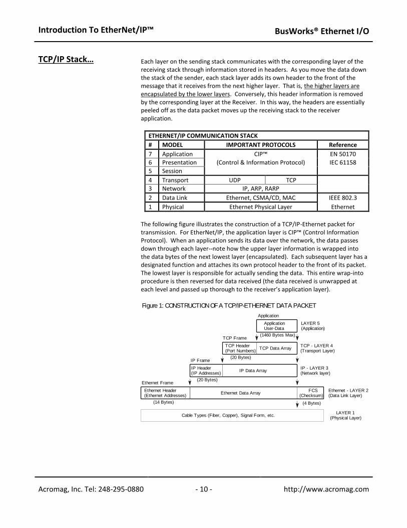
TCP/IP Stack… Each layer on the sending stack communicates with the corresponding layer of the receiving stack through information stored in headers. As you move the data down the stack of the sender, each stack layer adds its own header to the front of the message that it receives from the next higher layer. That is, the higher layers are encapsulated by the lower layers. Conversely, this header information is removed by the corresponding layer at the Receiver. In this way, the headers are essentially peeled off as the data packet moves up the receiving stack to the receiver application.
ETHERNET/IP COMMUNICATION STACK
# MODEL IMPORTANT PROTOCOLS Reference
7 Application CIP™ EN 50170
6 Presentation (Control & Information Protocol) IEC 61158
5 Session
4 Transport UDP TCP
3 Network IP, ARP, RARP
2 Data Link Ethernet, CSMA/CD, MAC IEEE 802.3
1 Physical Ethernet Physical Layer Ethernet
The following figure illustrates the construction of a TCP/IP-Ethernet packet for transmission. For EtherNet/IP, the application layer is CIP™ (Control Information Protocol). When an application sends its data over the network, the data passes down through each layer--note how the upper layer information is wrapped into the data bytes of the next lowest layer (encapsulated). Each subsequent layer has a designated function and attaches its own protocol header to the front of its packet. The lowest layer is responsible for actually sending the data. This entire wrap-into procedure is then reversed for data received (the data received is unwrapped at each level and passed up thorough to the receiver’s application layer).
(20 Bytes)
Ethernet Frame
Ethernet Header(Ethernet Addresses)
Ethernet Data Array
IP Data Array
TCP Data Array
TCP Frame(1460 Bytes Max)
Application
LAYER 1(Physical Layer)
Ethernet - LAYER 2(Data Link Layer)
(14 Bytes)
TCP Header(Port Numbers)
ApplicationUser-Data
Cable Types (Fiber, Copper), Signal Form, etc.
(4 Bytes)
FCS(Checksum)
(20 Bytes)
IP Frame
IP - LAYER 3(Network layer)
TCP - LAYER 4(Transport Layer)
LAYER 5(Application)
IP Header(IP Addresses)
Figure 1: CONSTRUCTION OF A TCP/IP-ETHERNET DATA PACKET
Introduction To EtherNet/IP™
BusWorks® Ethernet I/O
Acromag, Inc. Tel: 248-295-0880 - 11 - http://www.acromag.com - 11 - http://www.acromag.com
TCP/IP Stack… To illustrate, a host application forms its request, then passes its data down to the lower layers, which add their own control information to the packet in the form of protocol headers and footers. Finally the packet reaches the physical layer where it is electronically transmitted to the destination host. The packet then travels up through the different layers of its destination with each layer decoding its portion of the message and removing the header and footer that was attached by the same layer of the sending computer. Finally the packet reaches the destination application. Although each layer only communicates with the layer just above or just below it, this process can be viewed as one layer at one end talking to its partner layer at the opposite end.
Key Concepts & Terminology
To better understand EtherNet/IP and the operation of a stack, please review the following key concepts and terminology:
All network functions are structured as a layered model.
There's one or more protocols (layer entities) at every layer.
Peer entities refer to two or more protocols on the same layer. This may also refer to protocols at the same layer on different nodes.
Operation rules between peer entities are called procedures.
Protocol refers to the rules of operation followed by peer entities. The Protocol defines the format of PDU’s (Protocol Data Units) and their rules of operation.
This layering of protocol entities is referred to as the protocol stack.
Layer n communicates with other layer n entities (other protocols on the same layer) using layer n Protocol Data Units (PDU’s).
Layer n uses the service of layer n-1 and offers a service to layer n+1.
The interface between a layer and the layer above it is referred to as the Service Access Point (SAP). The interface data between the layers is the Service Data Unit (SDU).
Protocols are either connection oriented or connectionless. A connection implies that the communication requires synchronization of all parties before data can be exchanged.
EtherNet/IP follows the Client-Server model.
A server is any program that awaits data requests to be sent to it. Servers do not initiate contact with clients, but only respond to them.
A client is any network device that sends data requests to servers.
A port is an address that is used locally at the transport layer (on one node) and identifies the source and destination of the packet inside the same node. Port numbers are divided between well-known port numbers (0-1023), registered user port numbers (1024-49151), and private/dynamic port numbers (49152-65535). Ports allow TCP/IP to multiplex and demultiplex a sequence of IP datagrams that need to go to many different (simultaneous) application processes.
A socket is an application layer address that is formed from the combination of an IP address and port number (expressed as <Host IP Address>:<Port Number> or <Host Name>:<Port Number>) and is used as the overall identification address of an application process. Application protocols use this to keep track of the port number assigned to each instance of an application when using UDP or TCP.
Introduction To EtherNet/IP™ BusWorks® Ethernet I/O
Acromag, Inc. Tel: 248-295-0880 - 12 - http://www.acromag.com - 12 - http://www.acromag.com
APPLICATION LAYER
The uppermost layer of the TCP/IP and OSI Reference Models is the Application Layer. There are many application layer protocols that may reside here, such as FTP, Telnet, HTTP, SMPT, DNS, and NNTP, among others. While each of these protocols has their own specific purpose, for EtherNet/IP, the primary application layer protocol of interest is CIP™ (Control Information Protocol).
Object-Oriented Terminology
Before we look at CIP™, we have to become familiar with some basic object oriented concepts and terminology, as CIP™ is built using objects.
An object is defined by attributes and behaviors. The term attributes refers to the information that differentiates one object from another. We use attributes to refer to the data of an object. The data stored within an object defines the state of the object. We use the term behaviors to refer to the operations or methods the object uses to manipulate its data or attributes. The behavior of an object is what the object can do and this behavior is contained within its methods. You use methods to operate on the data. Every attribute of an object will have a corresponding method and you invoke a method by sending a message to it. Messages are the communication mechanism between objects. CIP™ object models will use “get” and “set” messages as the methods to access their data.
Thus, we define an object as an entity that contains both data and behavior. This is key to understanding what an object is—that is, it combines the data and the behavior into one complete package. In this way, we also say that the object encapsulates its data and behavior. Contrast this to non-object oriented or procedural programming, in which the data and the behavior are kept separate.
In this way, there is no global data in an object. The object controls access to its attributes and methods, and some object members (both data and methods) are hidden from other objects. As a rule, objects do not normally manipulate the internal data of other objects. Access to the attributes within the object are controlled by the object itself. The restriction of access to certain attributes and method functions is referred to as data hiding. Details not important to the use of an object should be hidden from other objects and an object should only reveal the interface necessary to interact with it.
Objects are also modeled after classes. A class is like a template from which specific objects are made. In this way, the class is like a blueprint for the object. Because objects are created from classes, the classes must define the basic building blocks of objects (its data, behavior, and messages). A class will define the attributes and behaviors that all objects created from this class will possess.

Introduction To EtherNet/IP™
BusWorks® Ethernet I/O
Acromag, Inc. Tel: 248-295-0880 - 13 - http://www.acromag.com - 13 - http://www.acromag.com
CIP™ – Control & Information Protocol With CIP™, a class exists simply to combine data for I/O messaging among common elements and the CIP™ library already contains many commonly defined objects or classes. The confusion that surrounds this topic usually arises from the nesting of objects and classes that occurs in defining other objects and classes, and in linking together these various objects to build larger device profiles.
The TCP/IP protocol suite (or stack of independent protocols) provides all the resources for two devices to communicate with each other over an Ethernet Local-Area Network (LAN), or global Wide-Area Network (WAN). However, TCP/IP only guarantees that application messages will be transferred between these devices, it does not guaranty that these devices will actually understand or interoperate with one another. For EtherNet/IP devices, this capability is provided by the Control and Information Protocol (CIP™), or its more modern reference, the Common Industrial Protocol. EtherNet/IP, ControlNet, and DeviceNet all share the Control and Information Protocol (CIP™) at their application layer. For example, DeviceNet is basically CIP™ running on a CAN bus. Similarly, EtherNet/IP is CIP™ over TCP/UDP/IP. Because ControlNet, DeviceNet, and EtherNet/IP all have CIP™ in common, they also share an extensive object library and collection of pre-defined device profiles. CIP™ is built using the distributed object model. That is, this model combines appropriate functionality with data by way of distributed objects. These objects are used to model the behavior of varied application entities. An object is an instance of a class and contains member functions (methods) that are only specified in the class as operations. Although CIP™ defines a public set of operation, the methods of implementation are separate and application-specific. Object oriented applications make it easy to hide data and implementation details by using hierarchies of classes and other object oriented features. All CIP™ devices are modeled as a collection of objects. An object represents a particular component of a device. Each object has properties (data) and methods (commands). We use the term class to refer to a specific type or set of objects (same kind of system components), and object instance to refer to one implementation of a class (the object instance is the actual representation of a particular object within a class). Each instance of a class has the same attributes, but its own particular set of attribute values. The term attribute refers to a characteristic of an instance, an object, or an object class. Attributes provide status information and govern the operation of an object. Services are used to trigger the object/class to perform a task. The object’s response is referred to as its behavior. This collection of related data values and common elements that make up the device form its object model. Note that the term object and class are often used interchangeably, even though a class is really a specific type of object. Users access these objects through the application layer and this access remains the same, regardless of which network type hosts the device. The application programmer doesn’t even need to know to which network a device is connected, as this operation remains transparent to him. To summarize, we say that a class is a specific type of object. An instance is one implementation of a class, and an attribute is a characteristic of an instance. For example, if our object is fruit, we can say that an apple is a class of fruit. A Macintosh apple is an instance of this class, and red skin is one attribute of this particular instance. A class exists simply to combine data for I/O messaging among common elements. The CIP™ library already contains many commonly defined objects or classes and there are at least 46 object classes currently defined.

Introduction To EtherNet/IP™
BusWorks® Ethernet I/O
Acromag, Inc. Tel: 248-295-0880 - 14 - http://www.acromag.com - 14 - http://www.acromag.com
CIP™ - Control & Information Protocol…
The ability of different devices from different vendors to communicate up through the application layer makes them interoperable. Thus, on any network, in order for two devices to be fully interoperable, they must share a common application layer. To illustrate the benefits of sharing a common application layer protocol, consider that networks sometimes use devices called gateways to link networks of different types. The gateway converts one protocol to another. For example, an existing ProfiBus network can be linked to an Ethernet network via a gateway, but this is expensive and the conversion process is often slow. On the other hand, connecting a DeviceNet network to an Ethernet network is made much easier because they share the same application layer protocol. Although a gateway device may be used, the two networks only require a router that embeds the DeviceNet packet inside a TCP/IP packet to become interoperable. Because there is no conversion, the router is less complex, making it faster and less expensive.
For example, discrete input, discrete output, analog input, analog output, position controller, and AC drive are all classes defined in CIP™. These CIP™ objects or classes define the device access, behavior, and extensions, and this allows different device types to be accessed using a common mechanism—in this case, the object model. It’s important to make the distinction that the CIP™ standard does not specify how these objects are to be implemented, only what data values or attributes must be provided and made available to other CIP™ devices. The objects and their components are addressed by a uniform addressing scheme that utilizes the following:
Class Identifier or Class ID – An integer ID value assigned to each object class and accessible from the network.
Instance Identifier or Instance ID – An integer ID value assigned to an object instance that identifies it among all instances of the same class.
Attribute Identifier or Attribute ID – An integer ID value assigned to a class and/or instance attribute.
Service Code – An integer ID value which denotes a particular object instance and/or object class function.
Media Access Control Identifier (MAC ID) – An integer ID value assigned to each node on the network.
CIP™ makes use of object models to provide a standard method for transferring automation data between devices on the network. And because individual objects are only added to a device’s object model according to the specific functionality of the device, a device is not burdened with the unnecessary overhead of support for objects it can’t use. CIP™ already includes a large collection of commonly defined objects or object classes. While only a few of these objects are actually specific to the network link layer (only two objects are specific to EtherNet/IP for example—TCP/IP Interface Object & Ethernet Link Object), the majority are common objects that can be used across all CIP™ based networks. Though most devices will use some of these publicly defined objects, device vendors are free to create their own vendor-specific objects and these are denoted by class ID’s 100-199. EtherNet/IP devices are further grouped into two general device classes: adapters or scanners. Adapters are I/O devices which provide data to a scanner. For example, Acromag 9xxEN and XTxxx2 modules are adapters. Scanners are explicit I/O devices which configure adapters to produce their data. CIP™ uses the producer/consumer-based connection model, rather than the more traditional source/destination model. This model implies that as a message is produced onto the network, it is identified by its connection ID, not its destination address. Multiple nodes may also have the right to consume the data to which this connection ID refers. If a node wants to receive data, it only needs to ask for it one time in order to consume the data each time it is produced. Likewise, if a second node (or any number of additional nodes) require the same data, all they need to know is the connection ID to receive the same data simultaneously with all the other nodes.
Introduction To EtherNet/IP™
BusWorks® Ethernet I/O
Acromag, Inc. Tel: 248-295-0880 - 15 - http://www.acromag.com - 15 - http://www.acromag.com
CIP™ - Control & Information Protocol…
CIP™ provides many standard services for control of network devices and access to their data via implicit and explicit messages. Recall that implicit I/O messages refer to message exchanges that are time-sensitive (real-time), while explicit messages emphasize reliability and are used for messages that simply must get there. The type of messaging required will determine which specific transport layer protocol will be used, TCP (explicit/information), or UDP (implicit/control). The UDP/IP/MAC protocol stack will typically handle implicit messages and there are four general types of implicit messages: polled, change-of-state, cyclic, and strobed. The TCP/IP/MAC protocol stack will handle the explicit messages, which are simple point-to-point messages. The key thing to remember about implicit messages is that there can be many consumers of a single network packet and this requires UDP, while TCP is instead reserved for point-to-point messages. There are four general types of implicit messages supported by CIP™: polled, strobed, cyclic, and change-of-state. With EtherNet/IP, only polled and cyclic are used while DeviceNet and ControlNet use all four. Polled messages are those in which a master device (scanner) sequentially queries all of the slave devices (adapters) by sending them their output data, and receiving a reply with their input data. Strobed is a special case of polled in which the scanner sends out a single multicast request for data and the slaves sequentially respond with their data with no further messages required from the master. Cyclic messages are produced by a device according to a pre-determined schedule and are associated with a connection ID (cyclic messages are implicit). Any other device that requires the data of the producer is made aware of the connection ID and accepts the network packets associated with this connection ID. Change-of-state is like cyclic, except that its data is produced in response to an event which caused the data to change, rather than a timed schedule. Change-of-state devices must maintain a background cycle/rate (their heartbeat) to allow consuming devices to know that the node is online and functioning. At this point, it’s important to understand the distinction between the type of messaging that CIP™ may use. This type will then determine which lower level service and subsequent encapsulation will be performed, TCP/IP/MAC or UDP/IP/MAC. In general, the control portion of CIP™ makes use of real-time I/O messaging or implicit messaging. The information portion of CIP™ is used for simple message exchange or explicit messaging. TCP may only work with unicast (point-to-point) messages. UDP is typically used for implicit messages, while TCP is used for explicit messages as outlined in the following table:
Introduction To EtherNet/IP™
BusWorks® Ethernet I/O
Acromag, Inc. Tel: 248-295-0880 - 16 - http://www.acromag.com - 16 - http://www.acromag.com
CIP™ - Control & Information Protocol…
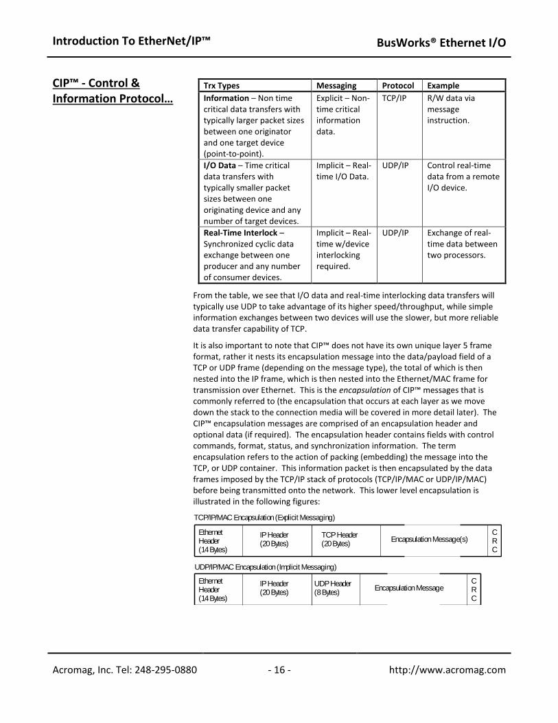
Trx Types Messaging Protocol Example
Information – Non time critical data transfers with typically larger packet sizes between one originator and one target device (point-to-point).
Explicit – Non-time critical information data.
TCP/IP R/W data via message instruction.
I/O Data – Time critical data transfers with typically smaller packet sizes between one originating device and any number of target devices.
Implicit – Real-time I/O Data.
UDP/IP Control real-time data from a remote I/O device.
Real-Time Interlock – Synchronized cyclic data exchange between one producer and any number of consumer devices.
Implicit – Real-time w/device interlocking required.
UDP/IP Exchange of real-time data between two processors.
From the table, we see that I/O data and real-time interlocking data transfers will typically use UDP to take advantage of its higher speed/throughput, while simple information exchanges between two devices will use the slower, but more reliable data transfer capability of TCP. It is also important to note that CIP™ does not have its own unique layer 5 frame format, rather it nests its encapsulation message into the data/payload field of a TCP or UDP frame (depending on the message type), the total of which is then nested into the IP frame, which is then nested into the Ethernet/MAC frame for transmission over Ethernet. This is the encapsulation of CIP™ messages that is commonly referred to (the encapsulation that occurs at each layer as we move down the stack to the connection media will be covered in more detail later). The CIP™ encapsulation messages are comprised of an encapsulation header and optional data (if required). The encapsulation header contains fields with control commands, format, status, and synchronization information. The term encapsulation refers to the action of packing (embedding) the message into the TCP, or UDP container. This information packet is then encapsulated by the data frames imposed by the TCP/IP stack of protocols (TCP/IP/MAC or UDP/IP/MAC) before being transmitted onto the network. This lower level encapsulation is illustrated in the following figures:
CRC
Encapsulation Message(s)
IP Header(20 Bytes)
UDP Header(8 Bytes)
TCP Header(20 Bytes)
IP Header(20 Bytes)
CRC
UDP/IP/MAC Encapsulation (Implicit Messaging)
TCP/IP/MAC Encapsulation (Explicit Messaging)
EthernetHeader(14 Bytes)
Encapsulation Message
EthernetHeader(14 Bytes)

Introduction To EtherNet/IP™
BusWorks® Ethernet I/O
Acromag, Inc. Tel: 248-295-0880 - 17 - http://www.acromag.com - 17 - http://www.acromag.com
CIP™ - Control & Information Protocol…
Some CIP™ messages are only sent via TCP, while others may be sent via TCP or UDP. As TCP is a data-stream based protocol, it may send almost any length IP packet it chooses, and it can parse this message as required. For example, it may encapsulate two back-to-back encapsulation messages in a single TCP/IP/MAC packet, or it may divide an encapsulation message across two separate TCP/IP/MAC packets. However, with UDP, only one message may be encapsulated at a time via UDP/IP/MAC. In general, there are three types of objects or classes defined by CIP™—required objects, application or device-specific objects, and vendor-specific objects. Required objects must be included in every CIP™ device. Device-specific objects are the objects that define the data encapsulated by the device and are specific to the type of device and its function. Objects not found in the profile for a device class are vendor-specific objects and these vendor extensions are usually included as additional features of the device. The confusion that surrounds this topic usually arises from the nesting of objects and classes that occurs in defining other objects and classes, and in linking together these various objects to build larger device profiles. Required objects must be included in every CIP™ device and these include an identity object, a message router object, and a network object. Most EtherNet/IP devices require the following objects:
An Identification Object (Identity Object)
A Connection Object (Connection Manager Object)
One or more Network Link Objects (Ethernet Link & TCP Objects)
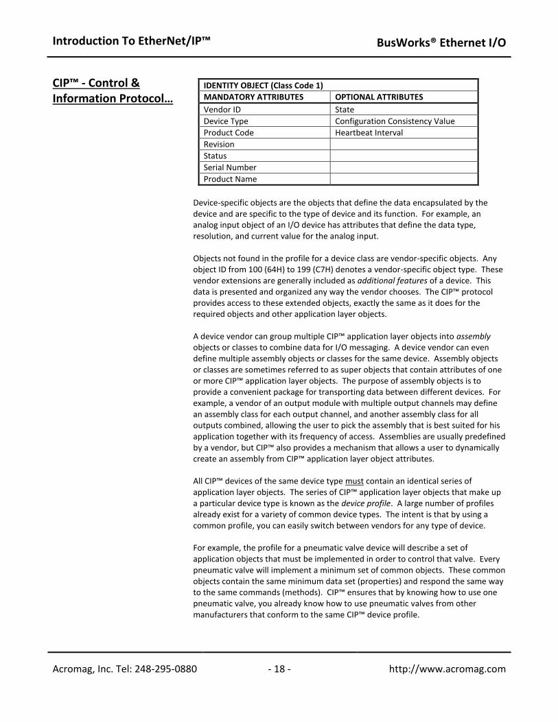
A Message Router Object (Message Router Object) The identity object contains related identity data values or attributes, including the vendor ID, date of manufacture, the device serial number, and other identity data. A network object contains the physical connection data for the object. For example, for a DeviceNet CIP™ device, the network object contains the MAC ID and other data describing the interface to the CAN network. For an EtherNet/IP device, the network object contains the IP address and other data describing the interface to the Ethernet port on the device. The message router object routes explicit request messages from object to object in a device. Additional objects are added to the device’s object model according to its functionality. The following table lists the instance attributes of the Identity Object (class code 1), which is a required public object. All the attributes of the identity object are read-only, as devices do not change their identity (except for the optional heartbeat interval attribute).
Introduction To EtherNet/IP™
BusWorks® Ethernet I/O
Acromag, Inc. Tel: 248-295-0880 - 18 - http://www.acromag.com - 18 - http://www.acromag.com
CIP™ - Control & Information Protocol…
IDENTITY OBJECT (Class Code 1)
MANDATORY ATTRIBUTES OPTIONAL ATTRIBUTES
Vendor ID State
Device Type Configuration Consistency Value
Product Code Heartbeat Interval
Revision
Status
Serial Number
Product Name
Device-specific objects are the objects that define the data encapsulated by the device and are specific to the type of device and its function. For example, an analog input object of an I/O device has attributes that define the data type, resolution, and current value for the analog input. Objects not found in the profile for a device class are vendor-specific objects. Any object ID from 100 (64H) to 199 (C7H) denotes a vendor-specific object type. These vendor extensions are generally included as additional features of a device. This data is presented and organized any way the vendor chooses. The CIP™ protocol provides access to these extended objects, exactly the same as it does for the required objects and other application layer objects. A device vendor can group multiple CIP™ application layer objects into assembly objects or classes to combine data for I/O messaging. A device vendor can even define multiple assembly objects or classes for the same device. Assembly objects or classes are sometimes referred to as super objects that contain attributes of one or more CIP™ application layer objects. The purpose of assembly objects is to provide a convenient package for transporting data between different devices. For example, a vendor of an output module with multiple output channels may define an assembly class for each output channel, and another assembly class for all outputs combined, allowing the user to pick the assembly that is best suited for his application together with its frequency of access. Assemblies are usually predefined by a vendor, but CIP™ also provides a mechanism that allows a user to dynamically create an assembly from CIP™ application layer object attributes. All CIP™ devices of the same device type must contain an identical series of application layer objects. The series of CIP™ application layer objects that make up a particular device type is known as the device profile. A large number of profiles already exist for a variety of common device types. The intent is that by using a common profile, you can easily switch between vendors for any type of device. For example, the profile for a pneumatic valve device will describe a set of application objects that must be implemented in order to control that valve. Every pneumatic valve will implement a minimum set of common objects. These common objects contain the same minimum data set (properties) and respond the same way to the same commands (methods). CIP™ ensures that by knowing how to use one pneumatic valve, you already know how to use pneumatic valves from other manufacturers that conform to the same CIP™ device profile.
Introduction To EtherNet/IP™
BusWorks® Ethernet I/O
Acromag, Inc. Tel: 248-295-0880 - 19 - http://www.acromag.com - 19 - http://www.acromag.com
CIP™ - Control & Information Protocol…
From a device manufacturer’s perspective, the use of common profiles may sound too restrictive for a manufacturer trying to offer unique features and capabilities to his products. But understand that although the use of common device profiles exist, a manufacturer may still incorporate additional features into its products via additional objects and attributes beyond those defined in the common device profile. A vendors’ conformance to an existing device profile simply allows his customers to define to a core set of objects and attributes without regard to the device manufacturer.
CIP™ Encapsulation Message
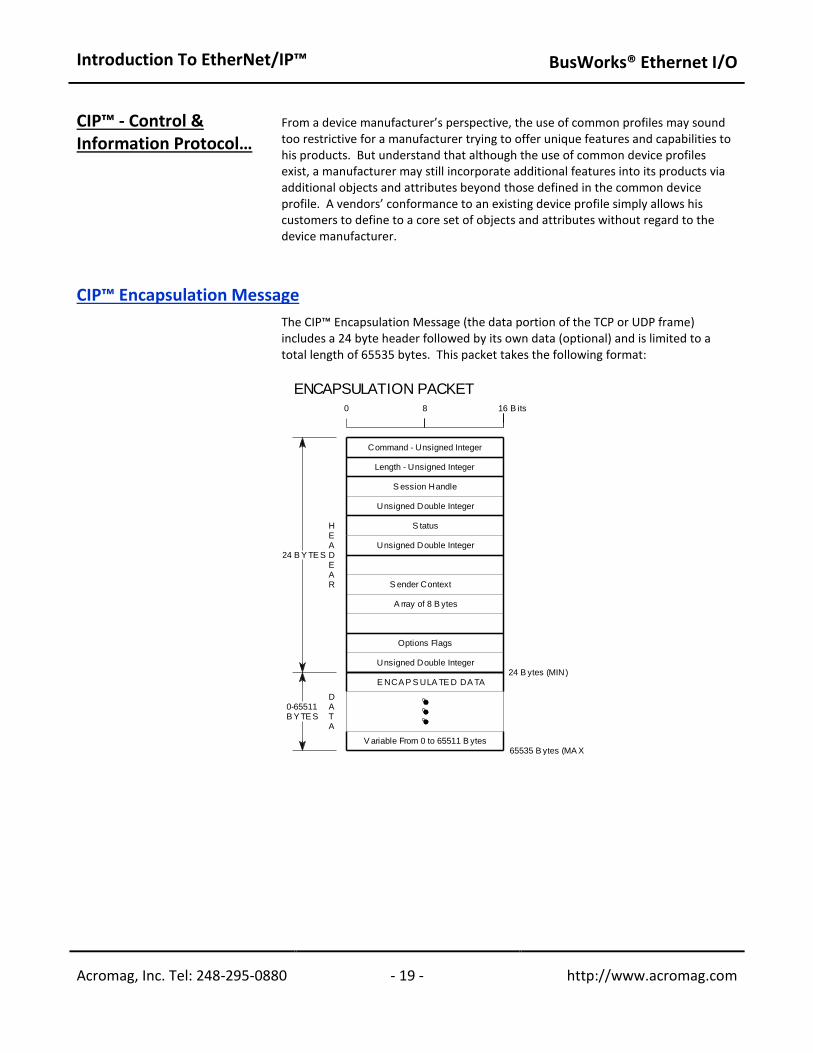
The CIP™ Encapsulation Message (the data portion of the TCP or UDP frame) includes a 24 byte header followed by its own data (optional) and is limited to a total length of 65535 bytes. This packet takes the following format:
8
24 B Y TE S
0
S tatus
B its
0-65511B Y TE S
DATA
HEADEAR
65535 B ytes (MA X )
24 B ytes (MIN)
16
V ariable From 0 to 65511 B ytes
Unsigned Double Integer
E NCA P S ULA TE D DA TA
Options Flags
A rray of 8 B ytes
Unsigned Double Integer
S ender Context
S ession Handle
Unsigned Double Integer
Command - Unsigned Integer
Length - Unsigned Integer
ENCAPSULATION PACKET
Introduction To EtherNet/IP™
BusWorks® Ethernet I/O
Acromag, Inc. Tel: 248-295-0880 - 20 - http://www.acromag.com - 20 - http://www.acromag.com
CIP™ Encapsulation Message…
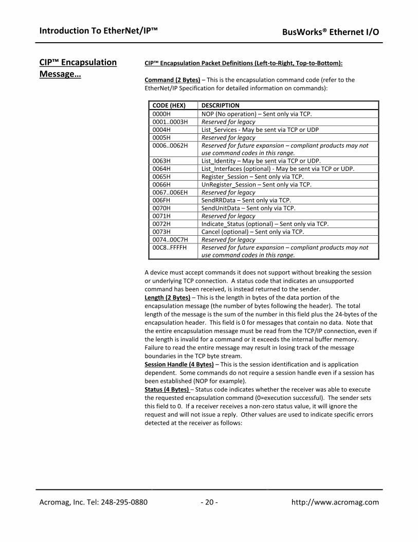
CIP™ Encapsulation Packet Definitions (Left-to-Right, Top-to-Bottom): Command (2 Bytes) – This is the encapsulation command code (refer to the EtherNet/IP Specification for detailed information on commands):
CODE (HEX) DESCRIPTION
0000H NOP (No operation) – Sent only via TCP. 0001..0003H Reserved for legacy 0004H List_Services - May be sent via TCP or UDP 0005H Reserved for legacy 0006..0062H Reserved for future expansion – compliant products may not
use command codes in this range. 0063H List_Identity – May be sent via TCP or UDP. 0064H List_Interfaces (optional) - May be sent via TCP or UDP. 0065H Register_Session – Sent only via TCP. 0066H UnRegister_Session – Sent only via TCP. 0067..006EH Reserved for legacy 006FH SendRRData – Sent only via TCP. 0070H SendUnitData – Sent only via TCP. 0071H Reserved for legacy 0072H Indicate_Status (optional) – Sent only via TCP. 0073H Cancel (optional) – Sent only via TCP. 0074..00C7H Reserved for legacy 00C8..FFFFH Reserved for future expansion – compliant products may not
use command codes in this range.
A device must accept commands it does not support without breaking the session or underlying TCP connection. A status code that indicates an unsupported command has been received, is instead returned to the sender. Length (2 Bytes) – This is the length in bytes of the data portion of the encapsulation message (the number of bytes following the header). The total length of the message is the sum of the number in this field plus the 24-bytes of the encapsulation header. This field is 0 for messages that contain no data. Note that the entire encapsulation message must be read from the TCP/IP connection, even if the length is invalid for a command or it exceeds the internal buffer memory. Failure to read the entire message may result in losing track of the message boundaries in the TCP byte stream. Session Handle (4 Bytes) – This is the session identification and is application dependent. Some commands do not require a session handle even if a session has been established (NOP for example). Status (4 Bytes) – Status code indicates whether the receiver was able to execute the requested encapsulation command (0=execution successful). The sender sets this field to 0. If a receiver receives a non-zero status value, it will ignore the request and will not issue a reply. Other values are used to indicate specific errors detected at the receiver as follows:
Introduction To EtherNet/IP™
BusWorks® Ethernet I/O
Acromag, Inc. Tel: 248-295-0880 - 21 - http://www.acromag.com - 21 - http://www.acromag.com
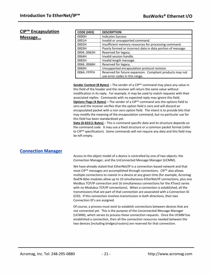
CIP™ Encapsulation Message…
CODE (HEX) DESCRIPTION
0000H Indicates Success 0001H Invalid or unsupported command. 0002H Insufficient memory resources for processing command. 0003H Poorly formed or incorrect data in data portion of message. 0004..0063H Reserved for legacy. 0064H Invalid session handle. 0065H Invalid length message. 0066..0068H Reserved for legacy. 0069H Unsupported encapsulation protocol revision. 006A..FFFFH Reserved for future expansion. Compliant products may not
use error codes in this range.
Sender Context (8 Bytes) – The sender of a CIP™ command may place any value in this field of the header and the receiver will return the same value without modification in its reply. For example, it may be used to match requests with their associated replies. Commands with no expected reply may ignore this field. Options Flags (4 Bytes) – The sender of a CIP™ command sets the options field to zero and the receiver verifies that the option field is zero and will discard an encapsulated packet with a non-zero option field. The intent is to provide bits that may modify the meaning of the encapsulation command, but no particular use for this field has been standardized yet. Data (0-65511 Bytes) – This is command specific data and its structure depends on the command code. It may use a fixed structure or a common packet format (refer to CIP™ specification). Some commands will not require any data and this field may be left empty.
Connection Manager Access to the object model of a device is controlled by one of two objects: the
Connection Manager, and the UnConnected Message Manager (UCMM). We have already stated that EtherNet/IP is a connection-based network and that most CIP™ messages are accomplished through connections. CIP™ also allows multiple connections to coexist in a device at any given time (for example, Acromag 9xxEN-60xx modules allow up to 10 simultaneous EtherNet/IP connections, plus one Modbus TCP/IP connection and 16 simultaneous connections for the XTxxx2 series with no Modubus TCP/IP connections). When a connection is established, all the transmissions that are part of that connection are associated with a Connection ID (CID). If this connection involves transmission in both directions, then two Connection ID’s are assigned. Of course, a process must exist to establish connections between devices that are not connected yet. This is the purpose of the Unconnected Message Manager (UCMM), which serves to process these connection requests. Once the UCMM has established a connection, then all the connection resources needed between the two devices (including bridges/routers) are reserved for that connection.

Introduction To EtherNet/IP™
BusWorks® Ethernet I/O
Acromag, Inc. Tel: 248-295-0880 - 22 - http://www.acromag.com - 22 - http://www.acromag.com
Connection Manager… Because UDP and IP are unacknowledged transmission protocols, a producer has no way of knowing if a consumer is online and receiving the data. In order to provide a mechanism that will shut down a connection when a consumer is no longer connected to the network, the producer will first establish a special “cyclic” connection to each of the consuming devices. No application data is actually transmitted through this connection, which is called a “heartbeat”.
If the producer times out all of the heartbeat connections that are associated with a specific produced data object, then all connections associated with that data object are closed. All connections on a CIP™ network can be divided into I/O connections (implicit), and explicit messaging connections. Recall that explicit message connections are point-to-point communication paths between two devices. They follow a simple request/response network communication format and are always made to the message router (the Message Router Object). Each request contains explicit information (not time critical) that the receiving node decodes and acts upon, then generates an appropriate response. Thus, all explicit connections are direct connections between two devices, which require a source address, a destination address, and a connection ID in each direction. Explicit messages are normally triggered by events that are external to the CIP™ application layer. Implicit message connections provide dedicated special purpose communication paths (or ports) between a producer application object and one or more consumer application objects. They follow the producer/consumer-based connection model and contain implicit (time-sensitive data. The data is implicit because it is identified at the time that the connection is established and the connection ID’s are assigned and we say that the data is implicitly defined by its connection ID. Implicit messaging is commonly used for I/O messages and takes place within the application layer of the protocol with both the producer node and consuming nodes aware of the message content before transmission. Its chief distinction is that there can be many simultaneous consumers of a single packet of data produced on the network. For implicit communication, the UDP/IP/MAC protocol stack is used, which supports the requisite multicast communication (UDP also supports unicast and broadcast communication, while TCP is restricted to unicast only). UDP packets are not transmitted directly to the actual IP address of a receiving device, but are transmitted using a specific device allocated IP multicast address. This address is used in parallel with the CIP™ connection ID, allowing packets that are not relevant to a specific node to be filtered out ahead of being presented to the application layer. But the consuming device must first be made aware of this IP multicast address (which was allocated by the producer) before it can use the data produced. The Unconnected Message Manager is used to accomplish this.

Introduction To EtherNet/IP™
BusWorks® Ethernet I/O
Acromag, Inc. Tel: 248-295-0880 - 23 - http://www.acromag.com - 23 - http://www.acromag.com
Connection Manager… For illustration, a point-to-point TCP packet is transmitted from the connection originator which indicates to a consumer the data object that it wishes to receive and the rate at which it wishes to receive it. The Connection Manager object is interrogated to determine if there is a match in its connection table to the data object and periodic rate. If it finds a match, then the data object is already being produced (it is a multicast message) and the Connection ID and related multicast IP address will be returned to the prospective consumer. If there is no match, then a UDP related IP address and Connection ID will be allocated and loaded into the Connection Manager object. The data will start being produced and may be consumed by any device already aware of its multicast IP address and Connection ID. This clever use of a TCP packet to establish a connection between devices, and then UDP to actually pipe the I/O data object serves to conserve network bandwidth.
Introduction To EtherNet/IP™
BusWorks® Ethernet I/O
Acromag, Inc. Tel: 248-295-0880 - 24 - http://www.acromag.com - 24 - http://www.acromag.com
TRANSPORT LAYER The Transport Layer resides just below the Application Layer and is responsible for the transmission, reception, and error checking of the data. There are a number of Transport Layer protocols that may operate at this layer, but the primary ones of interest are TCP and UDP. The application layer may choose to send its message using either the TCP or UDP transport layer protocols, depending on whether it is placing emphasis on speed (UDP), or reliability (TCP).
TCP- Transport Control Protocol With respect the port numbers commonly used in EtherNet/IP, UDP/UCM will use port 4418, UDP I/O will use port 2222, and CIP™ TCP will use 4418.
The Transport Control Protocol (TCP) resides one layer above the Internet Protocol (IP) and is responsible for transporting the application data and making it secure, while IP is responsible for the actual addressing and delivery of the data. From Figure 1 of the TCP/IP Stack section, note how the TCP packet is inserted into the data portion of the IP packet below it. IP itself is an unsecured, connectionless protocol and must work together with the overlaying TCP in order to operate. In this way, TCP is generally considered the upper layer of the IP platform that serves to guaranty secure data transfer. Some CIP™ application messages are not time-critical, and for this kind of data, it is more important that the data eventually arrive, than when it actually arrives. Thus, if this data is lost, it must be retransmitted. This type of data exchange refers to explicit messaging and is commonly used for exchanging information that is not time-critical, but necessary. That is, TCP uses explicit messaging and will ensure that a message is received, but not necessarily on time. TCP is a connection-oriented protocol. TCP establishes a connection between two network stations for the duration of the data transmission. While establishing this connection, conditions such as the size of the data packets are specified (which apply to the entire connection session). TCP works via the Client-Server communication model. That is, whichever network station takes the initiative and establishes the connection is referred to as the TCP Client. The station to whom the connection is made is called the TCP Server. The server does nothing on its own, but just waits for the client to make contact with it. The client then makes use of the service offered by the server (note that depending on the service, one server may accommodate several clients at one time). TCP verifies the sent user data with a checksum and assigns a sequential number to each packet sent. The receiver of a TCP packet uses the checksum to verify having received the data correctly. Once the TCP server has correctly received the packet, it uses a predetermined algorithm to calculate an acknowledgement number from the sequential number. The acknowledgement number is returned to the client with the next packet it sends as an acknowledgement. The server also assigns a sequential number to the packet it sends, which is then subsequently acknowledged by the client with an acknowledgement number. This process helps to ensure that any loss of TCP packets will be noticed and that if needed, they can then be re-sent in the correct sequence.
Introduction To EtherNet/IP™
BusWorks® Ethernet I/O
Acromag, Inc. Tel: 248-295-0880 - 25 - http://www.acromag.com - 25 - http://www.acromag.com
TCP – Transport Control Protocol…
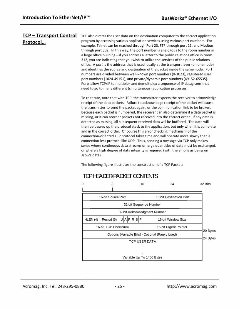
TCP also directs the user data on the destination computer to the correct application program by accessing various application services using various port numbers. For example, Telnet can be reached through Port 23, FTP through port 21, and Modbus through port 502. In this way, the port number is analogous to the room number in a large office building—if you address a letter to the public relations office in room 312, you are indicating that you wish to utilize the services of the public relations office. A port is the address that is used locally at the transport layer (on one node) and identifies the source and destination of the packet inside the same node. Port numbers are divided between well-known port numbers (0-1023), registered user port numbers (1024-49151), and private/dynamic port numbers (49152-65535). Ports allow TCP/IP to multiplex and demultiplex a sequence of IP datagrams that need to go to many different (simultaneous) application processes. To reiterate, note that with TCP, the transmitter expects the receiver to acknowledge receipt of the data packets. Failure to acknowledge receipt of the packet will cause the transmitter to send the packet again, or the communication link to be broken. Because each packet is numbered, the receiver can also determine if a data packet is missing, or it can reorder packets not received into the correct order. If any data is detected as missing, all subsequent received data will be buffered. The data will then be passed up the protocol stack to the application, but only when it is complete and in the correct order. Of course this error checking mechanism of the connection-oriented TCP protocol takes time and will operate more slowly than a connection-less protocol like UDP. Thus, sending a message via TCP only makes sense where continuous data streams or large quantities of data must be exchanged, or where a high degree of data integrity is required (with the emphasis being on secure data). The following figure illustrates the construction of a TCP Packet:
8
.
.
.
A P S F
0 16 24
20 Bytes
24 Bytes
32 Bits
U R
16-bit TCP Checksum 16-bit Urgent Pointer
HLEN (4) Resrvd (6)
16-bit Source Port
16-bit Window Size
16-bit Destination Port
Variable Up To 1460 Bytes
TCP USER DATA
Options (Variable Bits) - Optional (Rarely Used)
32-bit Acknowledgment Number
32-bit Sequence Number
TCP HEADER/PACKET CONTENTS
Introduction To EtherNet/IP™
BusWorks® Ethernet I/O
Acromag, Inc. Tel: 248-295-0880 - 26 - http://www.acromag.com - 26 - http://www.acromag.com
TCP – Transport Control Protocol…
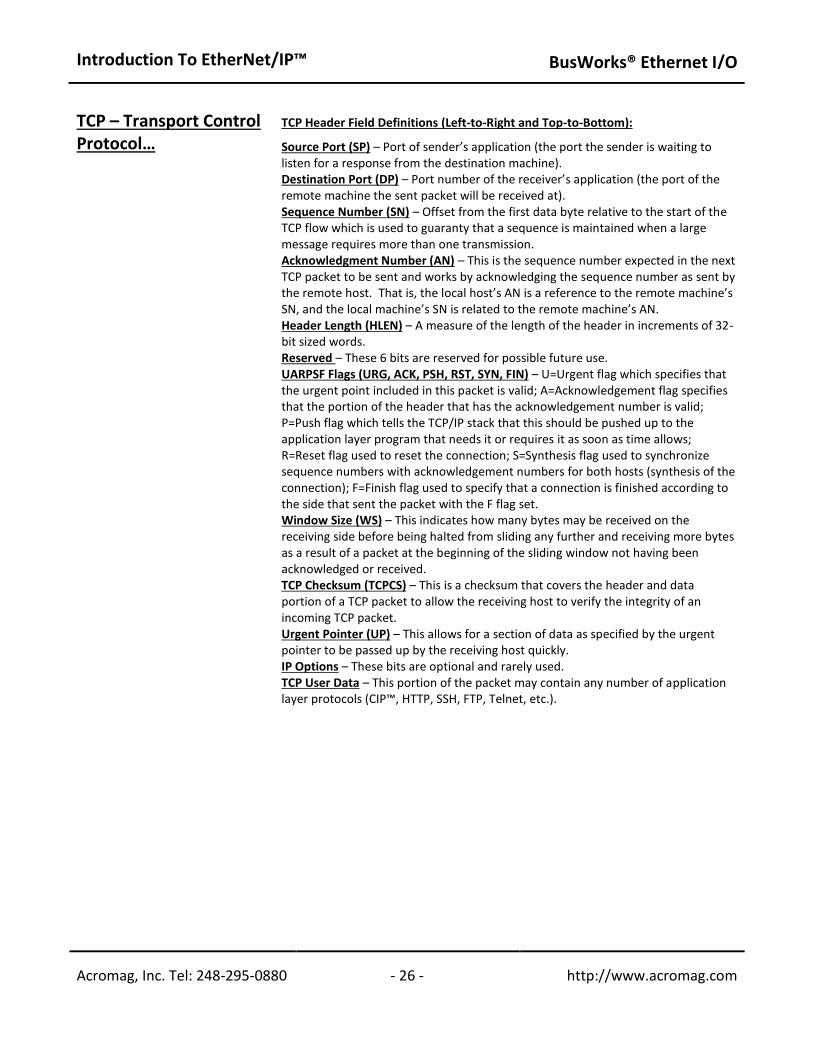
TCP Header Field Definitions (Left-to-Right and Top-to-Bottom): Source Port (SP) – Port of sender’s application (the port the sender is waiting to listen for a response from the destination machine). Destination Port (DP) – Port number of the receiver’s application (the port of the remote machine the sent packet will be received at). Sequence Number (SN) – Offset from the first data byte relative to the start of the TCP flow which is used to guaranty that a sequence is maintained when a large message requires more than one transmission. Acknowledgment Number (AN) – This is the sequence number expected in the next TCP packet to be sent and works by acknowledging the sequence number as sent by the remote host. That is, the local host’s AN is a reference to the remote machine’s SN, and the local machine’s SN is related to the remote machine’s AN. Header Length (HLEN) – A measure of the length of the header in increments of 32-bit sized words. Reserved – These 6 bits are reserved for possible future use. UARPSF Flags (URG, ACK, PSH, RST, SYN, FIN) – U=Urgent flag which specifies that the urgent point included in this packet is valid; A=Acknowledgement flag specifies that the portion of the header that has the acknowledgement number is valid; P=Push flag which tells the TCP/IP stack that this should be pushed up to the application layer program that needs it or requires it as soon as time allows; R=Reset flag used to reset the connection; S=Synthesis flag used to synchronize sequence numbers with acknowledgement numbers for both hosts (synthesis of the connection); F=Finish flag used to specify that a connection is finished according to the side that sent the packet with the F flag set. Window Size (WS) – This indicates how many bytes may be received on the receiving side before being halted from sliding any further and receiving more bytes as a result of a packet at the beginning of the sliding window not having been acknowledged or received. TCP Checksum (TCPCS) – This is a checksum that covers the header and data portion of a TCP packet to allow the receiving host to verify the integrity of an incoming TCP packet. Urgent Pointer (UP) – This allows for a section of data as specified by the urgent pointer to be passed up by the receiving host quickly. IP Options – These bits are optional and rarely used. TCP User Data – This portion of the packet may contain any number of application layer protocols (CIP™, HTTP, SSH, FTP, Telnet, etc.).
Introduction To EtherNet/IP™
BusWorks® Ethernet I/O
Acromag, Inc. Tel: 248-295-0880 - 27 - http://www.acromag.com - 27 - http://www.acromag.com
DFT RST
9
5
1
8
4
0
11
7
3
ETHERNET
ACTLINK
ST
NICC
H. I
/O S
TA
TU
S
10
6
2
RUN
Acromag
UDP
SAP
TCP
80
NETWORKROUTER
IP (Network Layer)
1 - OPEN (SYN)
Ethernet (Data Link Layer)
TCP UDP
SAP
CLIENT(WEB Browser)
Open Connection To255.255.255.100: 80
Physical Layer
Ethernet (Data Link Layer)
IP (Network Layer)
Passively Open(Listening)
IP Address is255.255.255.100Client PC Running Internet Explorer
Physical Layer (CAT5 Cable) Physical Layer (CAT5 Cable)
Ethernet (Data Link Layer)
2 - CONNECT (SYN ACK)
Application - WEB BROWSER Application - CIP, WEB SERVER
SIMPLIFIED CLIENT STACK SIMPLIFIED SERVER STACK
IP (Network Layer)
Acromag 983EN-6012
SIMPLIFIED ROUTER STACK
Socket Address is255.255.255.100:80
3 - CONNECT ACK (ACK) AND SEND DATA
EXAMPLE TCP TRANSACTION
PEER-TO-PEER COMMUNICATION80 is Web ServerPort Number forHTTP Protocol
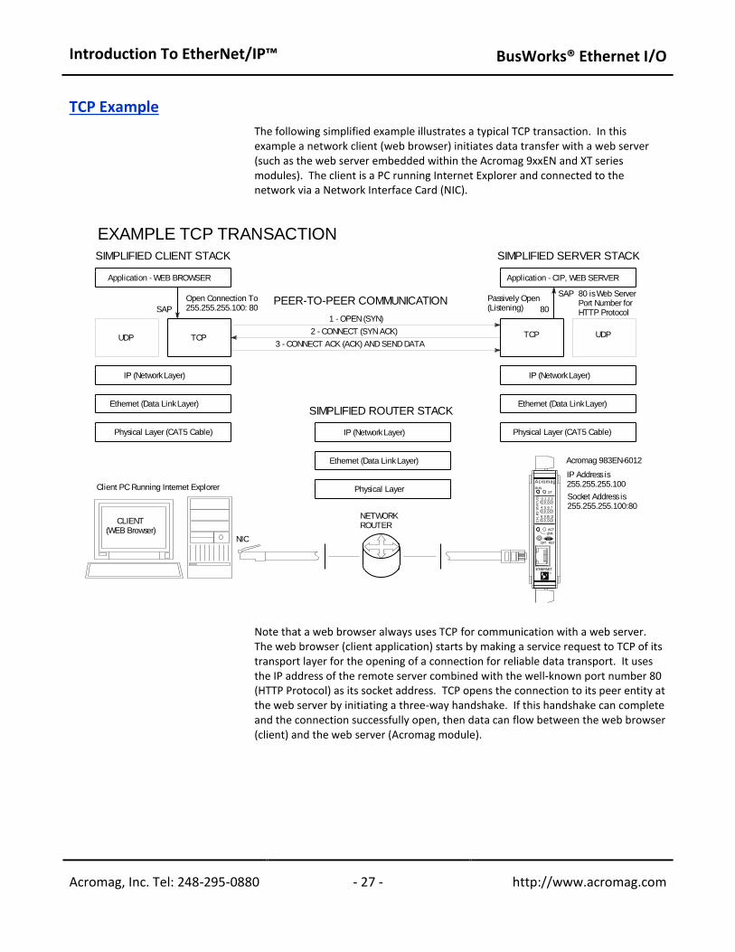
TCP Example
The following simplified example illustrates a typical TCP transaction. In this example a network client (web browser) initiates data transfer with a web server (such as the web server embedded within the Acromag 9xxEN and XT series modules). The client is a PC running Internet Explorer and connected to the network via a Network Interface Card (NIC).
Note that a web browser always uses TCP for communication with a web server. The web browser (client application) starts by making a service request to TCP of its transport layer for the opening of a connection for reliable data transport. It uses the IP address of the remote server combined with the well-known port number 80 (HTTP Protocol) as its socket address. TCP opens the connection to its peer entity at the web server by initiating a three-way handshake. If this handshake can complete and the connection successfully open, then data can flow between the web browser (client) and the web server (Acromag module).
Introduction To EtherNet/IP™
BusWorks® Ethernet I/O
Acromag, Inc. Tel: 248-295-0880 - 28 - http://www.acromag.com - 28 - http://www.acromag.com
TCP Example… Once the connection is made, the web browser and remote server assume that a reliable open data pipe has formed between them and they begin transporting their data in sequence, and without errors, as long as TCP does not close the connection. TCP will monitor the transaction for missing packets and retransmit them as necessary to ensure reliability. Note that in the figure above, an observer in the data paths at either side of the router would actually see the beginning of the message from the client to the web server begin only in the third data frame exchanged (the client’s request message is combined with the connection acknowledge of the third exchange).
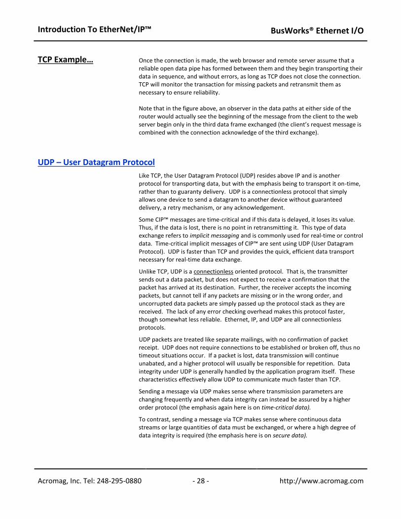
UDP – User Datagram Protocol
Like TCP, the User Datagram Protocol (UDP) resides above IP and is another protocol for transporting data, but with the emphasis being to transport it on-time, rather than to guaranty delivery. UDP is a connectionless protocol that simply allows one device to send a datagram to another device without guaranteed delivery, a retry mechanism, or any acknowledgement. Some CIP™ messages are time-critical and if this data is delayed, it loses its value. Thus, if the data is lost, there is no point in retransmitting it. This type of data exchange refers to implicit messaging and is commonly used for real-time or control data. Time-critical implicit messages of CIP™ are sent using UDP (User Datagram Protocol). UDP is faster than TCP and provides the quick, efficient data transport necessary for real-time data exchange. Unlike TCP, UDP is a connectionless oriented protocol. That is, the transmitter sends out a data packet, but does not expect to receive a confirmation that the packet has arrived at its destination. Further, the receiver accepts the incoming packets, but cannot tell if any packets are missing or in the wrong order, and uncorrupted data packets are simply passed up the protocol stack as they are received. The lack of any error checking overhead makes this protocol faster, though somewhat less reliable. Ethernet, IP, and UDP are all connectionless protocols. UDP packets are treated like separate mailings, with no confirmation of packet receipt. UDP does not require connections to be established or broken off, thus no timeout situations occur. If a packet is lost, data transmission will continue unabated, and a higher protocol will usually be responsible for repetition. Data integrity under UDP is generally handled by the application program itself. These characteristics effectively allow UDP to communicate much faster than TCP. Sending a message via UDP makes sense where transmission parameters are changing frequently and when data integrity can instead be assured by a higher order protocol (the emphasis again here is on time-critical data). To contrast, sending a message via TCP makes sense where continuous data streams or large quantities of data must be exchanged, or where a high degree of data integrity is required (the emphasis here is on secure data).
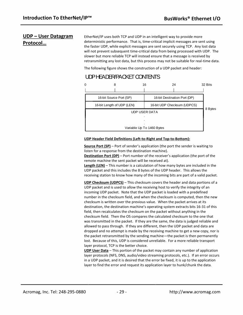
Introduction To EtherNet/IP™
BusWorks® Ethernet I/O
Acromag, Inc. Tel: 248-295-0880 - 29 - http://www.acromag.com - 29 - http://www.acromag.com
UDP – User Datagram Protocol…
EtherNet/IP uses both TCP and UDP in an intelligent way to provide more deterministic performance. That is, time-critical implicit messages are sent using the faster UDP, while explicit messages are sent securely using TCP. Any lost data will not prevent subsequent time-critical data from being processed with UDP. The slower but more reliable TCP will instead ensure that a message is received by retransmitting any lost data, but this process may not be suitable for real-time data. The following figure shows the construction of a UDP packet and header:
UDP Header Field Definitions (Left-to-Right and Top-to-Bottom): Source Port (SP) – Port of sender’s application (the port the sender is waiting to listen for a response from the destination machine). Destination Port (DP) – Port number of the receiver’s application (the port of the remote machine the sent packet will be received at). Length (LEN) – This number is a calculation of how many bytes are included in the UDP packet and this includes the 8 bytes of the UDP header. This allows the receiving station to know how many of the incoming bits are part of a valid packet. UDP Checksum (UDPCS) – This checksum covers the header and data portions of a UDP packet and is used to allow the receiving host to verify the integrity of an incoming UDP packet. Note that the UDP packet is loaded with a predefined number in the checksum field, and when the checksum is computed, then the new checksum is written over the previous value. When the packet arrives at its destination, the destination machine’s operating system extracts bits 16-31 of this field, then recalculates the checksum on the packet without anything in the checksum field. Then the OS compares the calculated checksum to the one that was transmitted in the packet. If they are the same, the data is judged reliable and allowed to pass through. If they are different, then the UDP packet and data are dropped and no attempt is made by the receiving machine to get a new copy, nor is the packet retransmitted by the sending machine—the packet is then permanently lost. Because of this, UDP is considered unreliable. For a more reliable transport layer protocol, TCP is the better choice. UDP User Data – This portion of the packet may contain any number of application layer protocols (NFS, DNS, audio/video streaming protocols, etc.). If an error occurs in a UDP packet, and it is desired that the error be fixed, it is up to the application layer to find the error and request its application layer to hunk/chunk the data.
0 8
.
.
.
16 24 32
8 BytesUDP USER DATA
Bits
16-bit Destination Port (DP)
16-bit UDP Checksum (UDPCS)
16-bit Source Port (SP)
UDP HEADER/PACKET CONTENTS
Variable Up To 1460 Bytes
16-bit Length of UDP (LEN)
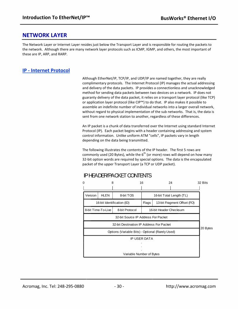
Introduction To EtherNet/IP™
BusWorks® Ethernet I/O
Acromag, Inc. Tel: 248-295-0880 - 30 - http://www.acromag.com - 30 - http://www.acromag.com
NETWORK LAYER The Network Layer or Internet Layer resides just below the Transport Layer and is responsible for routing the packets to the network. Although there are many network layer protocols such as ICMP, IGMP, and others, the most important of these are IP, ARP, and RARP.
IP - Internet Protocol
Although EtherNet/IP, TCP/IP, and UDP/IP are named together, they are really complimentary protocols. The Internet Protocol (IP) manages the actual addressing and delivery of the data packets. IP provides a connectionless and unacknowledged method for sending data packets between two devices on a network. IP does not guaranty delivery of the data packet, it relies on a transport layer protocol (like TCP) or application layer protocol (like CIP™) to do that. IP also makes it possible to assemble an indefinite number of individual networks into a larger overall network, without regard to physical implementation of the sub networks. That is, the data is sent from one network station to another, regardless of these differences. An IP packet is a chunk of data transferred over the Internet using standard Internet Protocol (IP). Each packet begins with a header containing addressing and system control information. Unlike uniform ATM "cells", IP packets vary in length depending on the data being transmitted. The following illustrates the contents of the IP header. The first 5 rows are commonly used (20 Bytes), while the 6
th (or more) rows will depend on how many
32-bit option words are required by special options. The data is the encapsulated packet of the upper Transport Layer (a TCP or UDP packet).
8
.
.
.
Version
0 16 24 32 Bits
16-bit Identification (ID)
8-bit TOSHLEN
20 Bytes
Flags
16-bit Total Length (TL)
13-bit Fragment Offset (FO)
8-bit Time-To-Live 16-bit Header Checksum
Variable Number of Bytes
IP USER DATA
32-bit Source IP Address For Packet
32-bit Destination IP Address For Packet
IP HEADER/PACKET CONTENTS
Options (Variable Bits) - Optional (Rarely Used)
8-bit Protocol
Introduction To EtherNet/IP™
BusWorks® Ethernet I/O
Acromag, Inc. Tel: 248-295-0880 - 31 - http://www.acromag.com - 31 - http://www.acromag.com
IP – Internet Protocol… IP Header Field Definitions (Left-to-Right and Top-to-Bottom): Version – A 4-bit field that specifies what version of the Internet Protocol is being used (currently IP version 4). IP version 6 has many advantages over IP version 4, but is not in widespread use yet. Header Length (HLEN) – A 4-bit number that specifies the increments of 32-bit words that tell the machine decoding the IP packet where the IP header is supposed to end (this dictates the beginning of the data). For example, “0101” (5) would specify an IP packet having only the first 5 rows as header information and its data thus beginning with the 6
th row.
Type-of-Service (TOS) – Used for special IP packet information that may be accessed by routers passing along the packet, or by receiving interfaces. The first 3 bits are reserved, the fourth bit is set to 0, and the remaining 4 bits are used to flag the following (respectively): minimize delay for this packet, maximize throughput for this packet, maximize reliability for this packet, and minimize monetary costs. Many application layer protocols have recommended values for each of these bits based on the kind of service they are using. For example, NNTP (Net News Transfer Protocol) is not a very time critical operation. NNTP is used for USENET posts, and group synchronization between servers, or to a client from a server. If it happens to take a long time to transfer all this data, that’s OK. Since it’s not time sensitive, the “minimize monetary costs” bit may be set for a server synchronizing itself with another server under these conditions. Thus, it is left to the router to determine the paths which are the cheapest and then route a packet based on the flags that are set. If a router has only two routes (one to/from the internet, a second to/from a Local Area Network), then these 4 bits are often ignored since there are not multiple routes to its destination. These bits may be useful where a router may have four routes to a distant network, each route using a medium that has specific costs related to bandwidth, reliability, or latency (fiber, satellite, LAN line, or VPN for example). With each of these links up through a router, an incoming packet may be routed via any of these paths, but a properly configured router may be able to take advantage of how these packet bits are set by the sender in determining which route to take. These bits are sometimes known as the Differentiated Services Code Point (DSCP) which defines one of a set of classes of service. This value is usually set to 0, but may be used to indicate a particular Quality of Service request from the network. Total Length (TL) – The total length of the IP packet in 8-bit (byte) increments. By subtracting header length (HL) from total length (TL), you can determine how many bytes long the data portion of the IP packet is. As a 16-bit value, valid ranges would be from 20 (minimum size of IP header) to 65535 bytes. A TL of only 20 is unlikely (no data), but could happen if something was broken. Very large IP packets (greater than 1500 bytes) are also uncommon, since they must typically be fragmented onto some networks. Identification (ID) – A 16-bit number used to distinguish one sent IP packet from another by having each IP packet sent increment the ID by 1 over the previous IP packet sent. Flags – A sequence of 3 fragmentation flags used to control where routers are allowed to fragment a packet (via Don’t Fragment flag) and to indicate the parts of a packet to the receiver: 001=More, 010=Don’t Fragment, 100= Unused.
Introduction To EtherNet/IP™
BusWorks® Ethernet I/O
Acromag, Inc. Tel: 248-295-0880 - 32 - http://www.acromag.com - 32 - http://www.acromag.com
IP – Internet Protocol…
A Network's Infrastructure includes the physical hardware used to transmit data electronically such as routers, switches, gateways, bridges, and hubs. A router is located at the gateway where it directs the flow of network traffic and determines the route of packets as they travel from one network to another network(s). A router can be either a hardware device or a software application.
Fragmentation Offset (FO) – A byte count from the start of the original packet sent and set by any router that performs IP router fragmentation.
Time-to-Live (TTL) – An 8-bit value that is used to limit the number of routers through which a packet may travel before reaching its destination (the number of hops/links which the packet may be routed over). This number is decremented by 1 by most routers and is used to prevent accidental routing loops. If the TTL drops to zero, the packet is discarded by either the server that has last decremented it, or the next server that receives it. Protocol – An 8-bit value that is used to allow the networking layer to know what kind of transport layer protocol is in the data segment of the IP packet. For example, 1=ICMP, 2=IGMP, 6=TCP, 17=UDP. Header Checksum – A 16-bit checksum (1’s complement value) for the header data that allows a packet to offer verification data to help ensure that the IP header is valid. This checksum is originally inserted by the sender and then updated whenever the packet header is modified by a router. This is used to detect processing errors on the part of the router or bridge where the packet is not already protected by a link layer cyclic redundancy check. Packets with an invalid checksum are discarded by all nodes in an IP network. Source IP Address (32 bits) – The IP address of the source machine sending the data onto the network. This address is commonly represented by 4 octets representing decimal values and separated by periods (255.255.255.10 for example). Destination IP Address (32 bits) – The IP address of the destination machine to which the packet is being routed for delivery. This address is commonly represented by 4 octets representing decimal values and separated by periods (255.255.255.10 for example). Options (Variable Number of Bits/Words) – These bits are reserved for special features and are rarely used, but when they are used, the IP header length will be greater than 5 (five 32-bit words) to indicate the relative size of the option field. IP Data (Variable Number of Bits/Words) - This portion of the packet may contain any number of nested protocols (TCP, UDP, ICMP, etc.).
Ethernet (MAC) Address
TIP: If you want to determine the Ethernet address of the NIC card installed in your PC, at the DOS command prompt, type WINIPCFG <Enter> (Windows 98), or IPCONFIG /ALL <Enter> (Windows XP).
The Ethernet Address or MAC Address refers to the Media Access Control Address that uniquely identifies the hardware of any network device. This is a unique, 48-bit, fixed address assigned and hard-coded into an Ethernet device at the factory. This is usually expressed in hexadecimal form as 12 hex characters (6 bytes), with the first 3 bytes (6 leftmost hex characters) representing the device manufacturer, and the last 3 bytes (6 rightmost hex characters) uniquely assigned by the manufacturer. All six bytes taken together uniquely identify the network device. Do not confuse the Ethernet Address (MAC address) with the Internet Protocol (IP) Address, which is a 32-bit number assigned to your computer (see below) that can change each time you connect to a network.
Introduction To EtherNet/IP™
BusWorks® Ethernet I/O
Acromag, Inc. Tel: 248-295-0880 - 33 - http://www.acromag.com - 33 - http://www.acromag.com
Internet (IP) Address A Subnet Mask is used to subdivide the host portion of the IP address into two or more subnets. The subnet mask will flag the bits of the IP address that belong to the network address, and the remaining bits correspond to the host portion of the address. The unique subnet to which an IP address refers to is recovered by performing a bitwise AND operation between the IP address and the mask itself, with the result being the sub-network address.
IP addresses are 32-bit numbers that are administered by an independent authority (InterNIC) and are unique for any device on the network. The IP address is a 32-bit value made up of four octets (8 bits), with each octet having a value between 0-255 (00H-FFH). It is commonly expressed as four decimal numbers (8-bit values) separated by a decimal point. This provides about 4.3 billion possible combinations. Large networks of corporations, communications companies, and research institutions will obtain large blocks of IP addresses, then divide them into subnetworks within their own organization and distribute these addresses as they see fit. The smaller networks of universities and companies will acquire smaller blocks of IP addresses to distribute among their users. Because these numbers are ultimately assigned by the Internet Assigned Number’s Authority, the IP address can be used to approximate a machine’s location. Similar to the Ethernet Address, the IP address is comprised of two parts: the network address or Net ID (first part), and the host address or Host ID (last part). This last part refers to a specific machine on a given subnetwork (identified by the first part). The number of octets of the four total that belong to the network address depend on the Class definition (Class A, B, or C) and this refers to the size of the network. A Subnet is a contiguous string of IP addresses. The first IP address in a subnet is used to identify the subnet and usually addresses the server for the subnet. The last IP address in a subnet is always used as a broadcast address and anything sent to the last IP address of a subnet is sent to every host on that subnet. Subnets are further broken down into three size classes based on the 4 octets that make up the IP address. A Class A subnet is any subnet that shares the first octet of the IP address. The remaining 3 octets of a Class A subnet will define up to 16,777,214 possible IP addresses (2
24 – 2). A Class B subnet shares the first two
octets of an IP address (providing 216
– 2, or 65534 possible IP addresses). Class C subnets share the first 3 octets of an IP address, giving 254 possible IP addresses. Recall that the first and last IP addresses are always used as a network number and broadcast address respectively, and this is why we subtract 2 from the total possible unique addresses that are defined via the remaining octet(s). A Subnet Mask is used to determine which subnet an IP address belongs to. The use of a subnet mask allows the network administrator to further divide the host part of this address into two or more subnets. The subnet mask flags the network address part of the IP address, plus the bits of the host part, that are used for identifying the sub-network. By mask convention, the bits of the mask that correspond to the sub-network address are all set to 1’s (it would also work if the bits were set exactly as in the network address). It’s called a mask because it can be used to identify the unique subnet to which an IP address belongs to by performing a bitwise AND operation between the mask itself, and the IP address, with the result being the sub-network address, and the remaining bits the host or node address.
Introduction To EtherNet/IP™
BusWorks® Ethernet I/O
Acromag, Inc. Tel: 248-295-0880 - 34 - http://www.acromag.com - 34 - http://www.acromag.com
Internet (IP) Address…
Note that the first node address (0) is typically reserved for the network server and should not be used. The last node (255) is a broadcast address. Use of these node addresses for any other purpose may yield poor performance.
For our example, the default IP address of this module is 128.1.1.100. If we assume that this is a Class C network address (based on the default Class C subnet mask of 255.255.255.0), then the first three numbers represent this Class C network at address 128.1.1.0, the last number identifies a unique host/node on this network (node 100) at address 128.1.1.100. For our example, if we wish to further divide this network into 14 subnets, then the first 4 bits of the host address will be required to identify the subnetwork (0110), then we would use “11111111.11111111.11111111. 11110000” as our subnet mask. This would effectively subdivide our Class C network into 14 subnetworks of up to 14 possible nodes each. With respect to the default settings of Acromag 9xxEN modules: Subnet Mask 255.255.255.0 IP Address: 128.1.1.100 Subnet Address: 128.1.1.0 Subnetwork address 128.1.1.0 has 254 possible unique node addresses. We are using node 100 of 254 possible for our module. With respect to the default settings of Acromag XTxxx2 modules: Subnet Mask: 255.255.255.0 IP Address: 192.168.1.100 Subnet Address: 192.168.1.0 Subnetwork address 192.168.1.0 has 254 possible unique node addresses. We are using node 100 of 254 possible for our module. At this point, we see that each layer (application, transport, network, and data link layer) uses its own address method. The application layer uses socket numbers, which combine the IP address with the port number. The transport layer uses port numbers to differentiate simultaneous applications. The network layer uses the IP address, and the Data Link layer uses the MAC address.

Introduction To EtherNet/IP™
BusWorks® Ethernet I/O
Acromag, Inc. Tel: 248-295-0880 - 35 - http://www.acromag.com - 35 - http://www.acromag.com
ARP – Address Resolution Protocol The ARP maps TCP/IP addresses to physical MAC addresses. Even though ARP is a layer 3 protocol, it does not use an IP header and has its own packet format that it broadcasts on the local LAN within the data field of a layer 2 frame, without needing to be routed (the Ethernet Type field of the layer 2 frame has the value 0806H in it to indicate an ARP request).
ARP is used to search for another station’s MAC address knowing only its IP address.
RARP is used to search for a local station’s IP address knowing only its MAC address.
The Address Resolution Protocol (ARP) is a TCP/IP function that resides at the network layer (layer 3) with the Internet Protocol (IP), and its function is to map Ethernet addresses (the MAC ID) to IP addresses and maintain a mapping table within the network device itself. This protocol allows a sending station to gather address information used to form a layer 2 frame complete with the IP address and hardware (MAC) address. Every TCP/IP-based device contains an ARP Table (or ARP cache) that is referred to by a router when it is looking up the hardware address of a device for which it knows the IP address and needs to forward a datagram to. If this device wants to transmit an IP packet to another device, it first attempts to look-up the Ethernet address of that device in its ARP table. If it finds a match, it will pass the IP packet and Ethernet address to the Ethernet driver (physical layer). If no hardware address is found in the ARP table, then an ARP broadcast is sent onto the network. The ARP protocol will query the network via a local broadcast message to ask the device with the corresponding IP address to return its Ethernet address. This broadcast is read by every connected station, including the destination station. The destination station sends back an ARP reply with its hardware address attached so that the IP datagram can now be forwarded to it by the router. The hardware address of the ARP response is then placed in an internal table and used for subsequent communication. ARP is used to search for another station’s MAC address knowing only its IP address. RARP is used to search for a local station’s IP address knowing only its MAC address. It is important to note that when we used the term “local broadcast message” above, that Ethernet broadcast messages will pass through hubs, switches, and bridges, but will not pass through routers. As such, broadcast messages are confined to the subnet on which they originate and will not propagate out onto the worldwide web. To make sure that the broadcast message is recognized by all connected network stations, the IP driver uses “FF FF FF FF FF FF” as the Ethernet address. The station that recognizes its own IP address in the ARP request will confirm this with an ARP reply. The ARP reply is a data packet addressed to the ARP request sender with an ARP identifier indicated in the protocol field of the IP header. The IP driver then extracts the Ethernet address obtained from the ARP reply and enters it into the ARP table. Normally, these dynamic entries do not remain in the ARP table and are aged out, if the network station is not subsequently contacted within a few minutes (typically 2 minutes under Windows). The ARP table may also support static address entries, which are fixed addresses manually written into the ARP table and not subject to aging. Static entries are sometimes used for passing the desired IP address to new network devices which do not yet have an IP address. Recall that ARP allowed a station to recover the destination hardware (MAC) address when it knows the IP address. The Reverse Address Resolution Protocol (RARP) is a complimentary protocol used to resolve an IP address from a given hardware address (such as an Ethernet address). A station will use RARP to determine its own IP address (it already knows its MAC address).
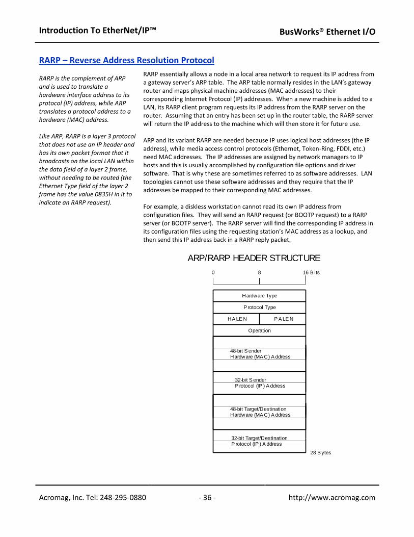
Introduction To EtherNet/IP™
BusWorks® Ethernet I/O
Acromag, Inc. Tel: 248-295-0880 - 36 - http://www.acromag.com - 36 - http://www.acromag.com
RARP – Reverse Address Resolution Protocol RARP is the complement of ARP and is used to translate a hardware interface address to its protocol (IP) address, while ARP translates a protocol address to a hardware (MAC) address. Like ARP, RARP is a layer 3 protocol that does not use an IP header and has its own packet format that it broadcasts on the local LAN within the data field of a layer 2 frame, without needing to be routed (the Ethernet Type field of the layer 2 frame has the value 0835H in it to indicate an RARP request).
RARP essentially allows a node in a local area network to request its IP address from a gateway server’s ARP table. The ARP table normally resides in the LAN’s gateway router and maps physical machine addresses (MAC addresses) to their corresponding Internet Protocol (IP) addresses. When a new machine is added to a LAN, its RARP client program requests its IP address from the RARP server on the router. Assuming that an entry has been set up in the router table, the RARP server will return the IP address to the machine which will then store it for future use. ARP and its variant RARP are needed because IP uses logical host addresses (the IP address), while media access control protocols (Ethernet, Token-Ring, FDDI, etc.) need MAC addresses. The IP addresses are assigned by network managers to IP hosts and this is usually accomplished by configuration file options and driver software. That is why these are sometimes referred to as software addresses. LAN topologies cannot use these software addresses and they require that the IP addresses be mapped to their corresponding MAC addresses. For example, a diskless workstation cannot read its own IP address from configuration files. They will send an RARP request (or BOOTP request) to a RARP server (or BOOTP server). The RARP server will find the corresponding IP address in its configuration files using the requesting station’s MAC address as a lookup, and then send this IP address back in a RARP reply packet.
0
.
.
.
.
.
.
Operation
8
P A LE N
B its
28 B ytes
32-bit Target/DestinationP rotocol (IP ) A ddress
48-bit Target/DestinationHardware (MA C) A ddress
HA LE N
Hardware Type
P rotocol Type
16
48-bit S enderHardware (MA C) A ddress
32-bit S enderP rotocol (IP ) A ddress
ARP/RARP HEADER STRUCTURE
Introduction To EtherNet/IP™
BusWorks® Ethernet I/O
Acromag, Inc. Tel: 248-295-0880 - 37 - http://www.acromag.com - 37 - http://www.acromag.com
RARP – Reverse Address Resolution Protocol…
ARP/RARP Header Field Definitions (Left-to-Right, Top-to-Bottom): Hardware Type – Specifies a hardware interface type from which the sender requires a response. This is “1” for Ethernet. Protocol Type – This is the protocol type used at the network layer and is used to specify the type of high-level protocol address the sender has supplied. Hardware Address Length (HALEN) – This is the hardware address length in bytes which is “6” for an Ethernet (MAC Address). Protocol Address Length (PALEN) – This is the protocol address length in bytes which is “4” for a TCP/IP (IP Address). Operation Code – This code is commonly used to indicate whether the packet is an ARP request (1), or an ARP response (2). Valid codes are as follows: 1 = ARP Request; 2 = ARP Response; 3 = RARP Request; 4 = RARP Response; 5 = Dynamic RARP Request; 6 = Dynamic RARP Reply; 7 = Dynamic RARP Error; 8 = InARP Request; 9 = InARP Reply. Sender Hardware (MAC) Address – This is the 48-bit hardware (MAC) address of the source node. Sender Protocol (Software) Address – This is the 32-bit senders protocol address (the layer 3/network layer address—the IP address). Target/Destination Hardware (MAC) Address – Used in an RARP request. The RARP request response carries both the target hardware address (MAC address) and layer 3 address (IP address). Target/Destination Protocol (Software) Address – Used in an ARP request. The ARP response carries both the target hardware address (MAC address) and layer 3 address (IP address). Most network stations will send out a gratuitous ARP request when they are initializing their own IP stack. This is really an ARP request for their own IP address and is used to check for a duplicate IP address. If there is a duplicate IP address, then the stack does not complete its initialization.
DATA LINK LAYER The Data Link Layer or Host-to-Network Layer provides the protocol for connecting the host to the physical network. Specifically, this layer interfaces the TCP/IP protocol stack to the physical network for transmitting IP packets. Recall from Figure 1 of the TCP/IP Stack section, how the various protocols at each of the different layers are encapsulated (nested) into the data frame of the next lowest layer. That is, packets generally carry other packet types inside them and their function is to often contain or encapsulate other packets. In this section, we will look at the lowest encapsulation layer (often referred to as the data link layer or the MAC layer) where Ethernet resides. Note that bits are transmitted serially with the least significant bit of each byte transmitted first at the physical layer. However, when the frame is stored on most computers, the bits are ordered with the least significant bit of each byte stored in the rightmost position (bits are generally transmitted right-to-left within the octets, and the octets are transmitted left-to-right).

Introduction To EtherNet/IP™
BusWorks® Ethernet I/O
Acromag, Inc. Tel: 248-295-0880 - 38 - http://www.acromag.com - 38 - http://www.acromag.com
CSMA/CD – Carrier Sense Multiple Access w/CD
The data link layer also uses the CSMA/CD protocol (Carrier Sense Multiple Access w/ Collision Detection) to arbitrate access to the shared Ethernet medium. Recall that with CSMA/CD, any network device can try to send a data frame at any time, but each device will first try to sense whether the line is idle and available for use. If the line is available, the device will begin to transmit its first frame. If another device also tries to send a frame at approximately the same time (perhaps because of cable signaling delay), then a collision occurs and both frames are subsequently discarded. Each device then waits a random amount of time and retries its transmission until it is successfully sent.
MAC - Medium Access Control (MAC) Protocol
The Medium Access Control (MAC) protocol provides the services required to form the data link layer of Ethernet. This protocol encapsulates its data by adding a 14-byte header containing the protocol control information before the data, and appending a 4 byte CRC value after the data. The entire frame is preceded by a short idle period (the minimum inter-frame gap), and an 8-byte preamble.
Ethernet (MAC) Packet
The figure of the following page shows the construction of the Ethernet packet along with its preamble (via the MAC protocol). Note that the frame preamble is normally preceded by a short idle period that corresponds to the minimum inter-frame gap of 9.6 microseconds at 10Mbps. This idle time before transmission is to allow the receiver electronics at each station to settle after completion of the prior frame. Ethernet (MAC) Frame Definitions (Left-to-Right & Top-to-Bottom): Preamble & SFD (56-bits+8-bits SFD) – Technically, the preamble is not part of the Ethernet frame, but is used to synchronize signals between stations. It is comprised of a pattern of 62 alternating 1’s & 0’s, followed by two set bits “11” (the last 8-bits of this pattern are actually referred to as the Start-of-Frame Delimiter or SFD byte). This 8-byte preamble/SFD is also preceded by a small idle period that corresponds to the minimum inter-frame gap period of 9.6us (at 10Mbps). After transmitting a frame, the transmitter must wait for this period to allow the signal to propagate through the receiver of its destination. The preamble allows the receiver at each station to lock into the Digital Phase Lock Loop used to synchronize the receive data clock to the transmit data clock. When the first bit of the preamble arrives, the receiver may be in an arbitrary state (out of phase) with respect to its local clock. It corrects this phase during the preamble and may miss/gain a number of bits in the process. That is why the special pattern of two set bits (11) is used to mark the last two bits of the preamble. When it receives these two bits, it starts assembling the bits into bytes for processing by the MAC layer. When using Manchester encoding at 10Mbps, the 62 alternating 1/0 bits of the preamble will resemble a 5MHz square wave.
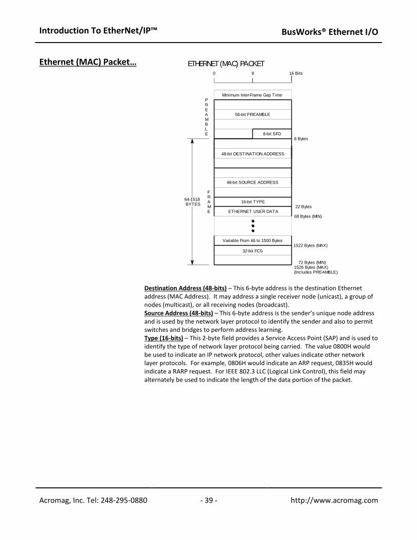
Introduction To EtherNet/IP™
BusWorks® Ethernet I/O
Acromag, Inc. Tel: 248-295-0880 - 39 - http://www.acromag.com - 39 - http://www.acromag.com
Ethernet (MAC) Packet…
Destination Address (48-bits) – This 6-byte address is the destination Ethernet address (MAC Address). It may address a single receiver node (unicast), a group of nodes (multicast), or all receiving nodes (broadcast). Source Address (48-bits) – This 6-byte address is the sender’s unique node address and is used by the network layer protocol to identify the sender and also to permit switches and bridges to perform address learning. Type (16-bits) – This 2-byte field provides a Service Access Point (SAP) and is used to identify the type of network layer protocol being carried. The value 0800H would be used to indicate an IP network protocol, other values indicate other network layer protocols. For example, 0806H would indicate an ARP request, 0835H would indicate a RARP request. For IEEE 802.3 LLC (Logical Link Control), this field may alternately be used to indicate the length of the data portion of the packet.
8
FRAME
.
.
.
0
8-bit SFD8 Bytes
16 Bits
PREAMBLE
32-bit FCS
16-bit TYPE64-1518 BYTES
1522 Bytes (MAX)
72 Bytes (MIN)
68 Bytes (MIN)
1526 Bytes (MAX)(Includes PREAMBLE)
22 Bytes
Variable From 46 to 1500 Bytes
ETHERNET USER DATA
48-bit SOURCE ADDRESS
48-bit DESTINATION ADDRESS
56-bit PREAMBLE
Minimum Inter-Frame Gap Time
ETHERNET (MAC) PACKET
Introduction To EtherNet/IP™ BusWorks® Ethernet I/O
Acromag, Inc. Tel: 248-295-0880 - 40 - http://www.acromag.com - 40 - http://www.acromag.com
Ethernet (MAC) Packet… CRC Cyclic Redundancy Check (32-bits) – The CRC is added at the end of a frame tosupport error detection for cases where line errors or transmission collisions result in a corrupted MAC frame. Any frame with an invalid CRC is discarded by a MAC receiver without further processing and the MAC protocol does not provide any other indication that a frame has been discarded due to an invalid CRC.
The Ethernet standard dictates a minimum frame size which requires at least 46 data bytes in a MAC frame. If a network layer tries to send less than 46 bytes of data, the MAC protocol adds the requisite number of 0 bytes (null padding characters) to satisfy this requirement. The maximum data size which may be carried in a MAC frame over Ethernet is 1500 bytes.
Any received frame less than 64 bytes is illegal and referred to as a “runt”. Runts may result from a collision and a receiver will discard all runt frames.
Any received frame which does not contain an integral multiple of octets (bytes) is also illegal (misaligned frame), as the receiver cannot compute the CRC for the frame and these will also be discarded by the receiver.
Any received frame greater than the maximum frame size is referred to as a “giant” and these frames are also discarded by an Ethernet receiver.
EDS (ELECTRONIC DATA SHEET) FILE
The object model of a device is of no use unless there is some mechanism for identifying which objects have been implemented in a device to an external application. This is the purpose of the Electronic Data Sheet.
All EtherNet/IP devices are required to provide an Electronic Data Sheet (EDS) file for device configuration. This file is used by various control software configuration tools and application programs to help identify and understand the capabilities of a remote EtherNet/IP device.
An EDS file is simply a text file used by network configuration tools to identify products and commission them on a network. For example, an EDS file describes a product's device type, product revision, and its configurable parameters on a network. Some devices embed the EDS file into hardware memory and do not require a separate physical (software) file.
EDS files must contain file revision information (File), identity object information (Device), device type information - DeviceNet, EtherNet/IP or ControlNet (Device Classification), physical connection information (Port), and connection information (Connection Manager).
EDS files may optionally contain parameter information used to configure specific attributes (Parameter), group information used to logically group parameters together (Group), enumeration information used to assign meaningful names to values (Enum), and other information.
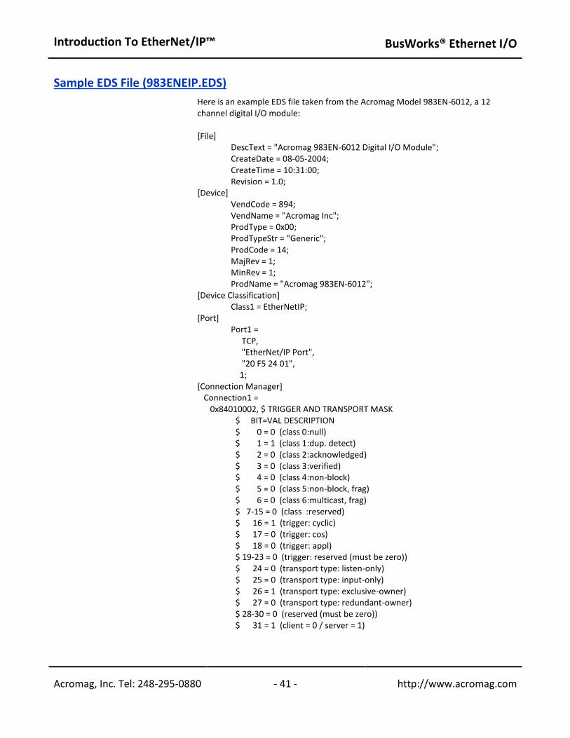
Introduction To EtherNet/IP™ BusWorks® Ethernet I/O
Acromag, Inc. Tel: 248-295-0880 - 41 - http://www.acromag.com - 41 - http://www.acromag.com
Sample EDS File (983ENEIP.EDS)
Here is an example EDS file taken from the Acromag Model 983EN-6012, a 12 channel digital I/O module:
[File] DescText = "Acromag 983EN-6012 Digital I/O Module"; CreateDate = 08-05-2004; CreateTime = 10:31:00; Revision = 1.0;
[Device] VendCode = 894; VendName = "Acromag Inc"; ProdType = 0x00; ProdTypeStr = "Generic"; ProdCode = 14; MajRev = 1; MinRev = 1; ProdName = "Acromag 983EN-6012";
[Device Classification] Class1 = EtherNetIP;
[Port] Port1 = TCP, "EtherNet/IP Port", "20 F5 24 01",
1; [Connection Manager] Connection1 = 0x84010002, $ TRIGGER AND TRANSPORT MASK
$ BIT=VAL DESCRIPTION $ 0 = 0 (class 0:null) $ 1 = 1 (class 1:dup. detect)
$ 2 = 0 (class 2:acknowledged) $ 3 = 0 (class 3:verified) $ 4 = 0 (class 4:non-block) $ 5 = 0 (class 5:non-block, frag) $ 6 = 0 (class 6:multicast, frag) $ 7-15 = 0 (class :reserved) $ 16 = 1 (trigger: cyclic) $ 17 = 0 (trigger: cos) $ 18 = 0 (trigger: appl) $ 19-23 = 0 (trigger: reserved (must be zero)) $ 24 = 0 (transport type: listen-only) $ 25 = 0 (transport type: input-only) $ 26 = 1 (transport type: exclusive-owner) $ 27 = 0 (transport type: redundant-owner) $ 28-30 = 0 (reserved (must be zero)) $ 31 = 1 (client = 0 / server = 1)
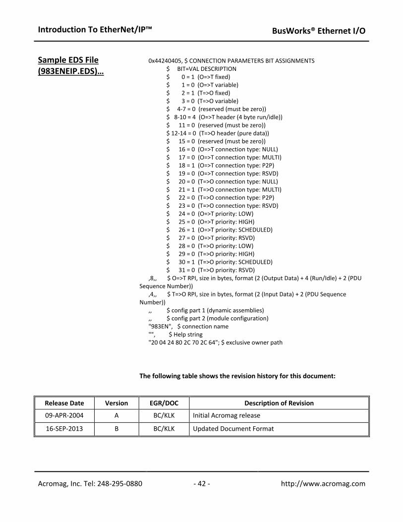
Introduction To EtherNet/IP™ BusWorks® Ethernet I/O
Acromag, Inc. Tel: 248-295-0880 - 42 - http://www.acromag.com - 42 - http://www.acromag.com
Sample EDS File (983ENEIP.EDS)…
0x44240405, $ CONNECTION PARAMETERS BIT ASSIGNMENTS $ BIT=VAL DESCRIPTION $ 0 = 1 (O=>T fixed) $ 1 = 0 (O=>T variable) $ 2 = 1 (T=>O fixed)
$ 3 = 0 (T=>O variable) $ 4-7 = 0 (reserved (must be zero)) $ 8-10 = 4 (O=>T header (4 byte run/idle)) $ 11 = 0 (reserved (must be zero)) $ 12-14 = 0 (T=>O header (pure data)) $ 15 = 0 (reserved (must be zero)) $ 16 = 0 (O=>T connection type: NULL) $ 17 = 0 (O=>T connection type: MULTI) $ 18 = 1 (O=>T connection type: P2P) $ 19 = 0 (O=>T connection type: RSVD) $ 20 = 0 (T=>O connection type: NULL) $ 21 = 1 (T=>O connection type: MULTI) $ 22 = 0 (T=>O connection type: P2P) $ 23 = 0 (T=>O connection type: RSVD) $ 24 = 0 (O=>T priority: LOW) $ 25 = 0 (O=>T priority: HIGH) $ 26 = 1 (O=>T priority: SCHEDULED) $ 27 = 0 (O=>T priority: RSVD) $ 28 = 0 (T=>O priority: LOW) $ 29 = 0 (T=>O priority: HIGH) $ 30 = 1 (T=>O priority: SCHEDULED) $ 31 = 0 (T=>O priority: RSVD)
,8,, $ O=>T RPI, size in bytes, format (2 (Output Data) + 4 (Run/Idle) + 2 (PDU Sequence Number)) ,4,, $ T=>O RPI, size in bytes, format (2 (Input Data) + 2 (PDU Sequence Number)) ,, $ config part 1 (dynamic assemblies) ,, $ config part 2 (module configuration) "983EN", $ connection name "", $ Help string "20 04 24 80 2C 70 2C 64"; $ exclusive owner path
Release Date Version EGR/DOC Description of Revision
09-APR-2004 A BC/KLK Initial Acromag release
16-SEP-2013 B BC/KLK Updated Document Format
The following table shows the revision history for this document:

Acromag manufactures signal conditioning and fieldbus I/O solutions. New distributed I/O modules support Ethernet IP, Profinet, Profibus, both Modbus TCP/IP and RTU. Process instruments include signal transmitter/converters, loop isolators, signal splitters, alarm trips, and computation modules. BusWorks® remote I/O modules for Ethernet IP, Profinet, Profibus and Modbus interface analog and discrete I/O signals.
Acromag I/O is ideal for a broad range of monitoring and control operations where controllers communicate with instrumentation on the plant floor or in the field. Signal conditioner products include process transmitters, 4-20mA signal isolators, limit alarms, panel meters, and math computation modules. These signal conditioning products isolate, amplify, filter, condition, and convert measured signals from sensors and other instruments. The enhanced signal is ready for interfacing to your PLC, DCS, display, recorder, or other process control instrumentation.
Acromag products are built to the highest quality standards. Manufacturing is located in Wixom Michigan and is ISO9001 and AS9100 certified. Acromag products are designed to be rugged. Many have CE, UL, cUL, ATEX certification and are approved for Class 1 Div 2 Zone 2 operation and temperatures from -40 to 80°C.
For more information about Acromag products, call the Inside Sales Department at (248) 295-0880, FAX (248) 624-9234. E-mail [email protected] or write Acromag at 30765 South Wixom Road, Wixom, MI48393-7037 USA. The website is www.acromag.com.
Introduction To EtherNet/IP™ ___________________________________________________________________
About Acromag
You might also like the white paper: How to Remotely Access Ethernet I/O Over the Internet
BusWorks® Ethernet I/O
Acromag, Inc. Tel: 248-295-0880 - 43 - http://www.acromag.com