
Introduction to DWDM
34
-
Upload
srotenstein3114 -
Category
Documents
-
view
23 -
download
1
description
Intro to DWDM
Transcript of Introduction to DWDM

2
What is Fiber Optics?
Transmission of communication signals in the form of light over thin glass or plastic (fiber).
Pulses of infrared light guided through glass fiber move huge blocks of data over long or short distances
Fiber Structure Propagation of Light in a Fiber

3
Options for Increasing the Bandwidth
More Fibers
Faster Electronics(TDM*)
WDM*
*TDM and WDM increase the effective capacity of the existing fiber
Increasing the number of wavelengthsSame fiber and bit rate, more wavelengths
Installing new fibersSame bit rate, more fibersVery Expensive
Increasing the bit rateHigher bit rate, same fiber
Expensive and Complex Electronics
4
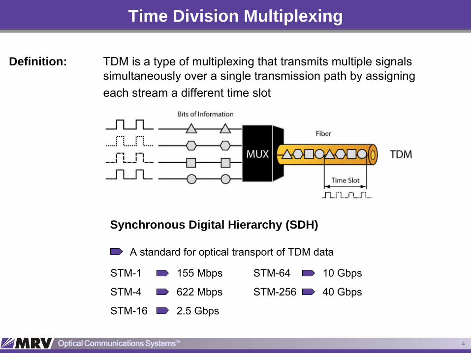
Time Division Multiplexing
Definition: TDM is a type of multiplexing that transmits multiple signals simultaneously over a single transmission path by assigning each stream a different time slot
Synchronous Digital Hierarchy (SDH)
A standard for optical transport of TDM data
STM-1
STM-4
STM-16
155 Mbps
622 Mbps
2.5 Gbps
STM-64
STM-256
10 Gbps
40 Gbps

5
TDM Limitations at Higher Bit Rate
Expensive and Complex Electronics
Complex Modulation
SNR Decreases
Very High Dispersion*
* Transmission at 40 Gbps
(STM-256) over single-mode (SM) fiber is 16 times more affected by dispersion than the transmission at 10 Gbps
(STM-64).

6
Wavelength Division Multiplexing (WDM)
Definition: Multiplexing several optical signals having different wavelengths and transmitting simultaneously over a single fiber is known as wavelength division multiplexing.(WDM increases the carrying capacity of the physical medium (fiber) using a completely different method from TDM)

7
TDM and WDM Comparison
►
Single wavelength per fiber►
Multiple channels per fiber►
E/O or O/E/O Conversion►
Common signal format►
Takes sync and async
signals and multiplexes them to a single higher optical bit rate
Time Division Multiplexing (TDM)
Wavelength Division Multiplexing (WDM)
►
Multiple wavelength per fiber (2, 4, 16, 64, etc.)►
Multiple channels per fiber►
No O/E Conversion►
Can carry multiple protocols►
Takes multiple optical signals and multiplexes them in to a single fiber

8
WDM History

9
WDM Evolution
Faster (Higher speed per channel)
Thicker (More channels)► 160 channels possible today
Longer (Link length before regeneration)► A few thousand km possible today
160 channels at 10 Gbps = 1.6 Tbps► 25 million simultaneous phone calls

10
Electromagnetic Spectrum

11
Fiber Performance
Definition: Loss of signal power in a transmission
Attenuation
DispersionDefinition: Broadening of the pulses as they travel along the fiber over long
distances
The strength of a signal traveling through an optical fiber wakens with distance

12
Fiber Attenuation Vs. Wavelength

13
Dispersion Slope for Different Fibers

14
Channel (Wavelength) Spacing
15
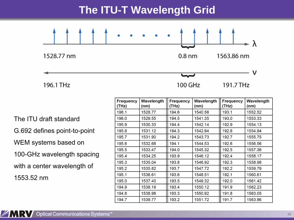
The ITU-T Wavelength Grid
The ITU draft standard
G.692 defines point-to-point
WEM systems based on
100-GHz wavelength spacing
with a center wavelength of
1553.52 nm

16
Optical Networking – The DWDM

17
DWDM Components - Transponder
High performance telecommunication laser
Long-haul links & DWDM systems
Key characteristics► Mostly around 1550 nm
► Total power 3 to 50 mw
► Spectral width 10 to 100 MHz (0.08 to 0.8 pm)
► Small NA (good coupling into fiber)
DWDM Laser – Distributed Feedback (DFB)

18
DWDM Components – Multiplexer & Demultiplexer
DWDM Multiplexer DWDM Demultiplexer

19
DWDM Components – Optical Add/Drop Multiplexer (OADM)

20
DWDM Components – Optical Amplifier (EDFA)
EDFA – Erbium Doped Fiber Amplifier
EDFA Construction
Simple device consisting of four parts►
Single wavelength per fiber►
Multiple channels per fiber►
E/O or O/E/O Conversion►
Common signal format

21
EDFA - Basics
Stimulated Emission When light hits the excited state electrons, their orbits decay from higher to the lower energy state and the atom releases the light from the source and the additional light that had been absorbed by the atom.► Same wavelength, direction, and phase
Spontaneous EmissionWhen an electron decays from a higher energy state to a lower energy state, the atom spontaneously emits the released light.
AbsorptionWhen light hits the atom, the electrons in the lower energy state absorb the energy and jump into higher energy state.
Absorption
Stimulated Emission
Spontaneous Emission

22
EDFA - Operation
Dope a fiber with Erbium
Pump energy into the fiber.
Transmit and amplify the signal

23
EDFA

24
EDFA – Input and Output Spectrum

25
DWDM with EDFA

26
EDFA Design Issues
The Main Parameters in the Design of an EDFA► Fiber glass material► Characteristics of the fiber► Erbium concentration profile► Erbium fiber length► Pump sources► Passive or active components such as couplers, isolators
Primary Design Goals► High gain► High output power► Low noise figure► Flatness of the gain spectrum► Reliability

27
EDFA Applications
Booster AmplifierEDFA is located with the transmitter and is used to boost the transmitter signal to a high level in order to drive a long fiber.
In-Line AmplifierIn an in-line amplifier configuration, the EDFA is used to amplify the weakening signal for further transmission down the line
Pre AmplifierThe pre-amplifier application is similar to in-line application. However, the EDFA is typically located with the receiver to amplify the signal just prior to its reception.

28
IP over DWDM
►
1 GbE
–
1GBase-SX and 1 GBase-LX-
DWDM implements up to 120 km, cascaded EDFAs
extend the reach to 1600+ km
►
10 GbE
–
10GBase-SR, 10 GBase-LR, and 10GBase-LX4-
DWDM implements up to 80 km, cascaded EDFAs
extend the reach to 1000+ km
WDM-Based
Map Ethernet Directly to a Wavelength
Increases the fiber capacity
Unidirectional and bi-directional wavelengths

29
Protocol Transparency
SDH/SONETATM
IPFast Ethernet
Gigabit EthernetFibre
ChannelFDDI
ESCON
SDH/SONETATM
IPFast Ethernet
Gigabit EthernetFibre
ChannelFDDI
ESCON
Data rate and format adaptation without reconfiguration

30
Network Management System
Functions of Network Management► Configuration Management
► Fault Management
► Performance Management
► Accounting Management
►Security Management
Network management is an essential element of communication systems since it is responsible for ensuring the efficient, secure, and continuous functioning of any network.

31
NMS – Functional Architecture

32
DWDM Benefits
Capacity Increase►
Large aggregate transmission capacity
Upgradability ►
Customer growth without requiring additional fiber to be laid
Flexibility►
Optical Add/Drop Multiplexing (OADM)►
Optical Cross Connect (OCC)
Scalability►
The possibility to addnew
nodes to the network
Network Transparency►
Independence of data rate, format and protocols

33
DWDM - Summary
DWDM provides enormous amounts of scalable transmission capacity
DWDM technology gives us the ability to expand fiber network rapidly tomeet growing demands of customer
The DWDM systems provide transparency to various bit rates and protocols
Utilizes the existing thin fiber
DWDM improves signal transmission
DWDM allows flexible add/drop of channels (OADMs)
Bi-directional communication using a single fiber can be achieved by the use of twodifferent wavelengths, one for each direction
Transmission over the longest possible distance with smallest number of opticalamplifiers
IP over DWDM

Optical Communication Systems
Thank You
We facilitate network operations, increase uptime and measure services over any fiber optic network, at any speed, distance, scale
and application diversity