Introduction to Digital Logic and Circuits EE 101, Fall 2015 University of Kentucky.
14
Introduction to Digital Logic and Circuits EE 101, Fall 2015 University of Kentucky
-
Upload
ambrose-reeves -
Category
Documents
-
view
218 -
download
1
Transcript of Introduction to Digital Logic and Circuits EE 101, Fall 2015 University of Kentucky.

Introduction to Digital Logic and CircuitsEE 101, Fall 2015
University of Kentucky

• What is digital logic• Binary and decimal numbers• Binary (or Boolean) logic– Truth tables
• Circuit elements• Circuit design– How we go from algebra to hardware
Outline

• Digital Logic is the foundation of digital computing– Required to understand and design modern
computers• Also important for other kinds of logic– Formal logic (philosophy, etc.)– Fuzzy logic (control systems, etc.)
• Expand your thinking!
Digital Logic – why?
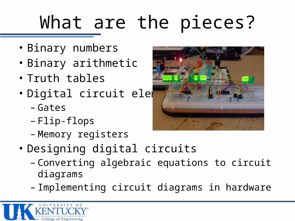
• Binary numbers• Binary arithmetic• Truth tables• Digital circuit elements– Gates– Flip-flops– Memory registers
• Designing digital circuits– Converting algebraic equations to circuit diagrams– Implementing circuit diagrams in hardware
What are the pieces?

• Binary numbers– Uses only 1’s and 0’s – Base-2 position numbering– Each position is a different power of 2• 1101 = 1x23 + 1x22 + 0x21 + 1x20 (= 13 in base-10)
• Recall decimal– Uses 0, 1, 2, …, 9– 98 = 9x101 + 8x100
Binary Numbers

Binary – to – Decimal

• Refers to operations on values that are either TRUE or FALSE– A useful way of viewing binary arithmetic
• TRUE/FALSE is easiest dichotomy to represent in a bistable environment – on/off (e.g., voltage on = 5 Volts, off = 0 Volts)– open/closed (e.g., open current = 0 Amps, closed = 1 Amp)
• Boolean logical operations implemented using transistors and other electronic devices– We rarely have to worry about those lower level details
(unless our job is to design better computing substrates, which could be fun…)
Boolean Logic (BL)

• Basic operations– AND (a AND b)• TRUE only when “a” and “b” are both TRUE
– OR (a OR b)• TRUE whenever “a” is true• TRUE whenever “b” is true
– NOT (NOT a)• TRUE whenever “a” is false• FALSE whenever “a” is true
BL – Basic Ops

• Boolean expressions– Combinations of Boolean operations– Example: (a AND b) OR ((NOT b) AND (NOT a))
• Truth tables capture the input/output relationships in a Boolean expression– One column for every input and every output– A row for each combination of input values
BL – Boolean Expressions

BL – Truth Table Examples

• (a AND b) OR ((NOT b) and (NOT a))– Create the truth table
BL – Truth Table Example

• Gates are hardware devices build from transistors that implement (or mimic) Boolean logic– Transform a set of input values (0’s and 1’s) into an
output value (0 or 1)
Gates

AND, OR, NOT Gates

• Gates are built from transistors
• Usually we don’t have to consider those lower-level details– (Lower-level does
NOT mean unimportant!)
Gate Hardware
Example of a NOT gate built using a BJT transistor and a resistor