EE 261 – Introduction to Logic Circuits Module #5 Page 1 EE 261 – Introduction to Logic Circuits...
77
EE 261 – Introduction to Logic Circuits Module #5 Page 1 EE 261 – Introduction to Logic Circuits Module #5 - VHDL • Topics A. Hardware Description Languages B. VHDL History C. VHDL Systems and Signals D. VHDL Entities, Architectures, and Packages E. VHDL Data Types F. VHDL Operators G. VHDL Structural Design H. VHDL Concurrent Signal Assignments • Textbook Reading Assignments 5.1, 5.3 • Practice Problems none • Graded Components of this Module 1 homework, 1 discussion, 1 quiz (all online)
-
Upload
kory-andrews -
Category
Documents
-
view
223 -
download
2
Transcript of EE 261 – Introduction to Logic Circuits Module #5 Page 1 EE 261 – Introduction to Logic Circuits...
EE 261 – Introduction to Logic Circuits Module #5Page 1
EE 261 – Introduction to Logic Circuits
Module #5 - VHDL• Topics
A. Hardware Description Languages
B. VHDL History
C. VHDL Systems and Signals
D. VHDL Entities, Architectures, and Packages
E. VHDL Data Types
F. VHDL Operators
G. VHDL Structural Design
H. VHDL Concurrent Signal Assignments
• Textbook Reading Assignments
5.1, 5.3
• Practice Problems none
• Graded Components of this Module 1 homework, 1 discussion, 1 quiz
(all online)

EE 261 – Introduction to Logic Circuits Module #5Page 2
EE 261 – Introduction to Logic Circuits
Module #5 - VHDL
• What you should be able to do after this module
Create a combinational logic circuit using Structural VHDL Create a combinational logic circuit using Concurrent Signal Assignments in VHDL

EE 261 – Introduction to Logic Circuits Module #5Page 3
Hardware Description Languages
• In the beginning…
1970's - designers used Paper/Pencil & Boolean Equations to create schematics - the drawback : - each flop required a Boolean equation - impractical in large designs
1980's - schematic based designs using electronic editors - this enabled Copy/Paste & Hierarchy - Design-reuse was enabled which increased design sizes
mid 80's - HDL's became more common (created mid 80's) - Text-based Compilers (C, PASCAL) could be adapted to perform digital simulation - Larger Designs could be described using text
SimulationPhysical
Implementation
Design
Still separate

EE 261 – Introduction to Logic Circuits Module #5Page 4
Hardware Description Languages
• More recently
1990's - Synthesis became practical due to increase in computational power of computers
Synthesis - the creation of circuitry from a functional description
ex) "Functional Description of MUX"
if (Sel = 0) Out = A else Out = B
SynthesisA
BOut
Sel

EE 261 – Introduction to Logic Circuits Module #5Page 5
Hardware Description Languages
• Real Power
1990's - Now engineers had a power combination
"Synthesis"
A
BOut
Sel
"HDL"
if (Sel = 0) Out = A else Out = B
"Simulation"

EE 261 – Introduction to Logic Circuits Module #5Page 6
Hardware Description Languages
• Abstraction
Engineers could now stay at a higher level of abstraction and rely on the tools to
1) Simulation 2) Synthesize the circuitry
- This allows larger systems to be described/designed in the same time
- Since HW is expensive to build, using the tools to reduce prototyping was the next step
EE 261 – Introduction to Logic Circuits Module #5Page 7
Hardware Description Languages
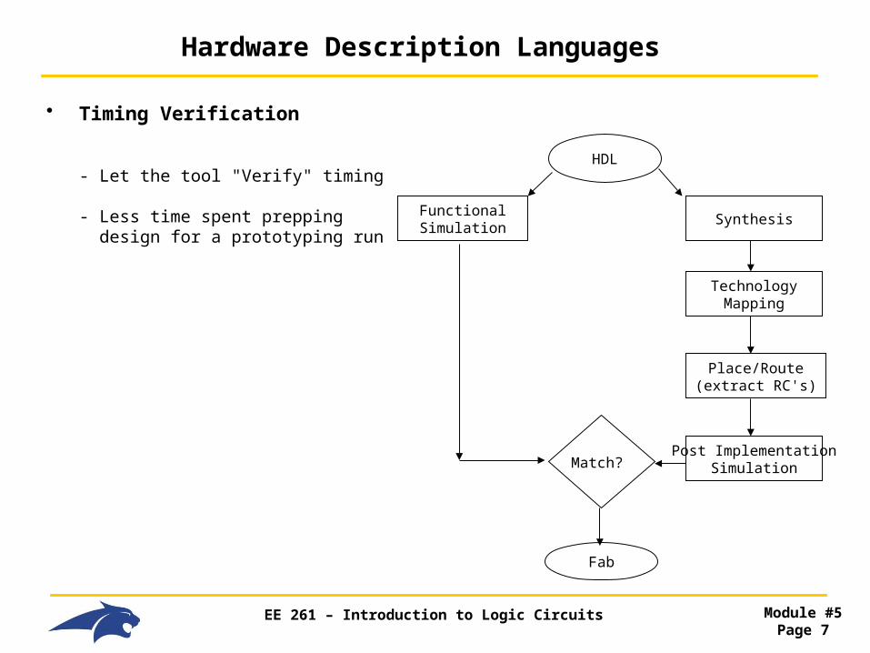
• Timing Verification
- Let the tool "Verify" timing
- Less time spent prepping design for a prototyping run
FunctionalSimulation
Synthesis
HDL
TechnologyMapping
Place/Route(extract RC's)
Post ImplementationSimulationMatch?
Fab

EE 261 – Introduction to Logic Circuits Module #5Page 8
VHDL History
• VHDL
V = Very High Speed Integrated CircuitH = HardwareD = DescriptionL = Language
- Originally a Department of Defense sponsored project in the 80's
- Original Intent was to Document Behavior (instead of writing system manuals)
- Original Intent was NOT synthesis, that came later
- Simulation was a given, since the designs were already in text and we had text compilers (C, ….)
- Designed by IBM, TI, Intermetrics (all sponsored by DoD)
EE 261 – Introduction to Logic Circuits Module #5Page 9
VHDL History
• VHDL & IEEE
- In 1987, IEEE published the "VHDL Standard"
- IEEE 1076-1987 = First formal version of VHDL - Strong "Data Typing"
- each signal/variable is typed (bit, bit_vector, real, integer)
- assignments between different types NOT allowed
- Did not handle multi-valued logic

EE 261 – Introduction to Logic Circuits Module #5Page 10
VHDL History
• VHDL & IEEE
- What is multi-valued logic?
- when there are more possible values than 0 and 1
- we need this for real world systems such as buses
- a bus is where multiple circuits drive and receive information - only one agent drives the bus (low impedance) - all other agents listen (high impedance)
- how can something drive AND receive?
- a "transceiver" has both a transmit (i.e., a gate facing out) and receive (i.e., a gate facing in)
- we can draw it as follows: Tx/Rx'
EE 261 – Introduction to Logic Circuits Module #5Page 11
VHDL History
• VHDL & IEEE
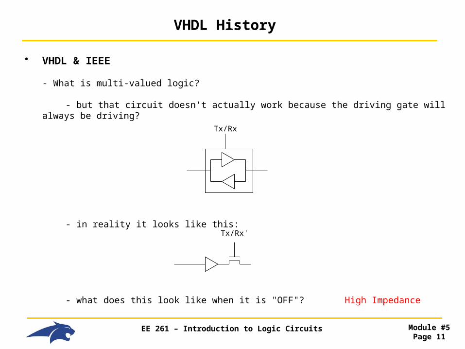
- What is multi-valued logic?
- but that circuit doesn't actually work because the driving gate will always be driving?
- in reality it looks like this:
- what does this look like when it is "OFF"? High Impedance
Tx/Rx
Tx/Rx'

EE 261 – Introduction to Logic Circuits Module #5Page 12
VHDL History
• VHDL & IEEE
- High Impedance
- it is how circuits behave, strong drivers will control the bus when everyone is High-Z
- When nobody is driving the bus, the bus is High-Z
- So for true behavior, VHDL has to model High-Z
- VHDL's built in types (bit and bit_vector) can only be 0 or 1, these don't cut it.
- Weak/Strong
- Some busses have multiple drivers but some are weaker than others (i.e., MCAN)?
- We should model these too
Tx/R
x
Tx/R
x
Tx/R
x

EE 261 – Introduction to Logic Circuits Module #5Page 13
VHDL History
• VHDL & IEEE
- VHDL allows users to come up with their own data types. Since the world needed multi-valued logic, everyone started creating their own add-on packages.
- this created a lot of confusion when multiple vendors worked together (i.e., Fab Shop and Designer)
- In 1993, IEEE published an Upgrade
- IEEE 1164 - added support for Multi-Valued Logic through the "STD_LOGIC" package - better syntax consistency
- Every time there is a need for a data type, industry will start to create add-ons. Then IEEE will create a standard to reduce confusion
- Other package standards that were added to VHDL
- 1076.2 = "Real and Complex Data Types" - 1076.3 = "Signed and Unsigned Data Types"
- The last rev of VHDL in 2003 (1076.3) is considered by most to be the more recent major release
- Although people are talking about VHDL 2006 (which now has turned into VHDL 200x)
EE 261 – Introduction to Logic Circuits Module #5Page 14
VHDL History
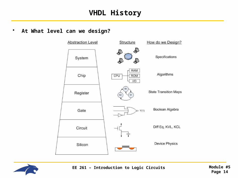
• At What level can we design?

EE 261 – Introduction to Logic Circuits Module #5Page 15
VHDL History
• What does abstraction give us?
- The higher in abstraction we go, the more complex & larger the system becomes
- But, we let go over the details of how it performs (speed, fine tuning)
- There are engineering jobs at each level
- Guru's can span multiple levels
• What does VHDL model?
- System : Chip : Register : Gate
- VHDL let's us describe systems in two ways:
1) Structural (text netlist) 2) Behavioral (requires synthesis)
EE 261 – Introduction to Logic Circuits Module #5Page 16
VHDL Systems and Signals
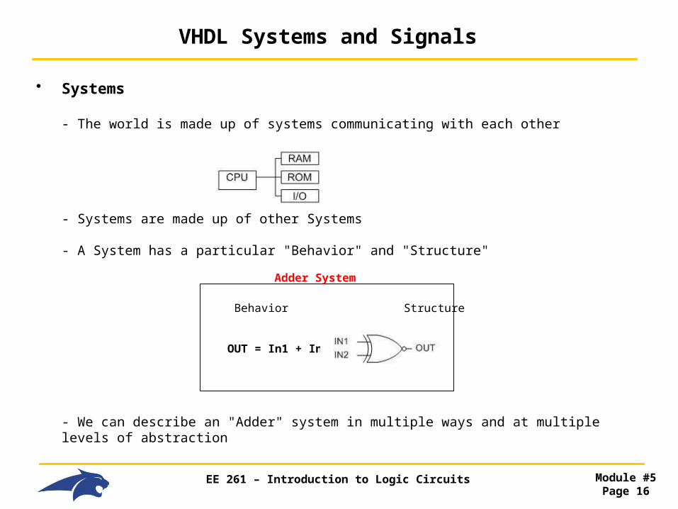
• Systems
- The world is made up of systems communicating with each other
- Systems are made up of other Systems
- A System has a particular "Behavior" and "Structure"
- We can describe an "Adder" system in multiple ways and at multiple levels of abstraction
Behavior Structure
OUT = In1 + In2
Adder System
EE 261 – Introduction to Logic Circuits Module #5Page 17
VHDL Systems and Signals
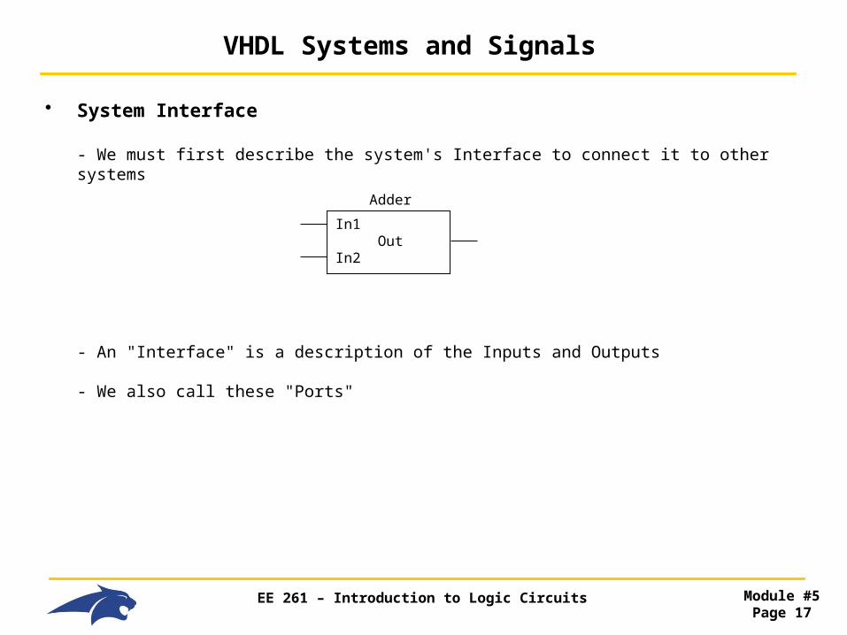
• System Interface
- We must first describe the system's Interface to connect it to other systems
- An "Interface" is a description of the Inputs and Outputs
- We also call these "Ports"
In1 OutIn2
Adder

EE 261 – Introduction to Logic Circuits Module #5Page 18
VHDL Systems and Signals
• System Behavior
- We then must describe the system's behavior (or functionality)
- There are many ways to describe the behavior in VHDL
- When describing a system, we must always describe its:
1) Interface 2) Behavior
In1 OutIn2
Adder

EE 261 – Introduction to Logic Circuits Module #5Page 19
VHDL Systems and Signals
• Signals
- Multiple Systems communicate with each other using signals
In1 OutIn2
Adder
In1 OutIn2
Adder
In1 OutIn2
Adder
External SignalsInternal Signals
EE 261 – Introduction to Logic Circuits Module #5Page 20
VHDL Entity
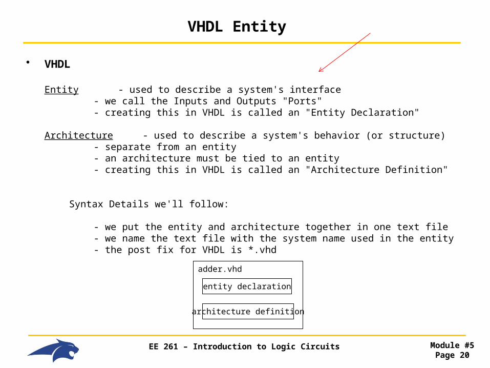
• VHDL
Entity - used to describe a system's interface - we call the Inputs and Outputs "Ports" - creating this in VHDL is called an "Entity Declaration"
Architecture - used to describe a system's behavior (or structure) - separate from an entity - an architecture must be tied to an entity - creating this in VHDL is called an "Architecture Definition"
Syntax Details we'll follow:
- we put the entity and architecture together in one text file - we name the text file with the system name used in the entity - the post fix for VHDL is *.vhd
adder.vhd
entity declaration
architecture definition
EE 261 – Introduction to Logic Circuits Module #5Page 21
VHDL Entity
• More Syntax Notes
- VHDL is NOT case sensitive- Comment text is proceeded with "--"- Names must start with an alphabetic letter (not a number)- Names can include underscore, but not two in a row (i.e., __) or as the last character.- Names cannot be keywords (in, out, bit, ….)

EE 261 – Introduction to Logic Circuits Module #5Page 22
VHDL Entity
• Entity Details
- an entity declaration must possess the following:
1) entity-name - user selected, same as text file
2) port-names - user selected
- mode - direction of signal (in, out, buffer, inout)
3) signal-type - what type of data is it? (bit, STD_LOGIC, real, integer, signed,…)
- this is where VHDL is strict!
- we say it is a "strong type cast" language
- there are built in (or pre-defined) types
(bit, bit_vector, boolean, character, integer, real, string, time)
- we can add more types for realistic behavior (i.e., buses)

EE 261 – Introduction to Logic Circuits Module #5Page 23
VHDL Entity
• Entity Syntax
entity entity-name is
port (signal-name : mode signal-type; signal-name : mode signal-type; signal-name : mode signal-type);
end entity entity-name;
NOTES: - the keywords are entity, is, port, end - multiple signal-names with the same type can be comma delimited on the same line - the port definition is contained within parenthesis - each signal-name line ends with a ";" except
the last line (watch the ");" at the end, this will get you every time!)

EE 261 – Introduction to Logic Circuits Module #5Page 24
VHDL Entity
• Entity Example
entity adder is
port (In1, In2 : in bit; Out1 : out bit);
end entity adder;
NOTES: - we can also put "Generics" within an entity, which are dynamic variables
ex) generic (BusWidth : Integer := 8);
more on generics later….
In1 Out1In2
adder.vhd
EE 261 – Introduction to Logic Circuits Module #5Page 25
VHDL Entity
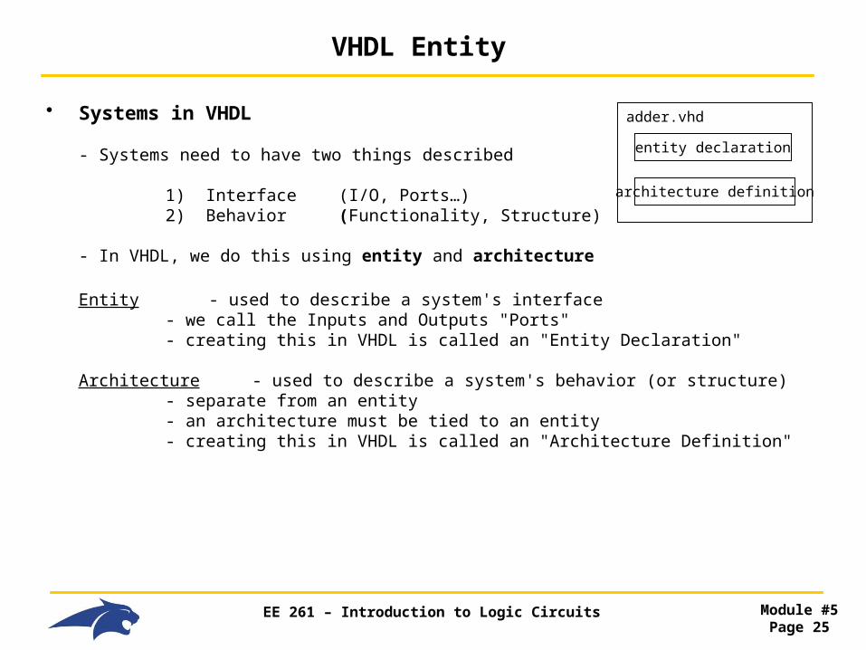
• Systems in VHDL
- Systems need to have two things described
1) Interface (I/O, Ports…) 2) Behavior (Functionality, Structure)
- In VHDL, we do this using entity and architecture
Entity - used to describe a system's interface - we call the Inputs and Outputs "Ports" - creating this in VHDL is called an "Entity Declaration"
Architecture - used to describe a system's behavior (or structure) - separate from an entity - an architecture must be tied to an entity - creating this in VHDL is called an "Architecture Definition"
adder.vhd
entity declaration
architecture definition

EE 261 – Introduction to Logic Circuits Module #5Page 26
VHDL Architecture
• Architecture Details
- an architecture is always associated with an entity (in the same file too)
- an architecture definition must possess the following:
1) architecture-name - user selected, different from entity - we usually give something descriptive (adder_arch, and2_arch) - some companies like to use "behavior", "structural" as the names
2) entity-name - the name of the entity that this architecture is associated with - must already be declared before compile
3) optional items… - types - signals : internal connections within the architecture - constants - functions : calling predefined blocks - procedures : calling predefined blocks - components : calling predefined blocks
4) end architecture - keywords to signify the end of the definition - we follow this by the architecture name and ";"
EE 261 – Introduction to Logic Circuits Module #5Page 27
VHDL Architecture
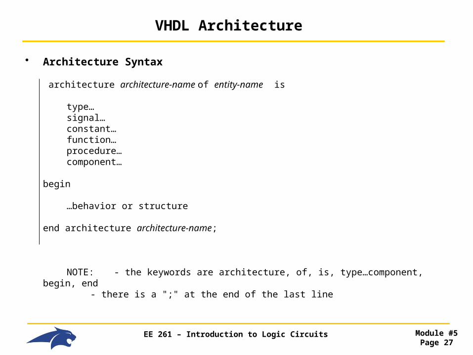
• Architecture Syntax
architecture architecture-name of entity-name is
type… signal… constant… function…
procedure…component…
begin
…behavior or structure end architecture architecture-name;
NOTE: - the keywords are architecture, of, is, type…component, begin, end - there is a ";" at the end of the last line
EE 261 – Introduction to Logic Circuits Module #5Page 28
VHDL Architecture
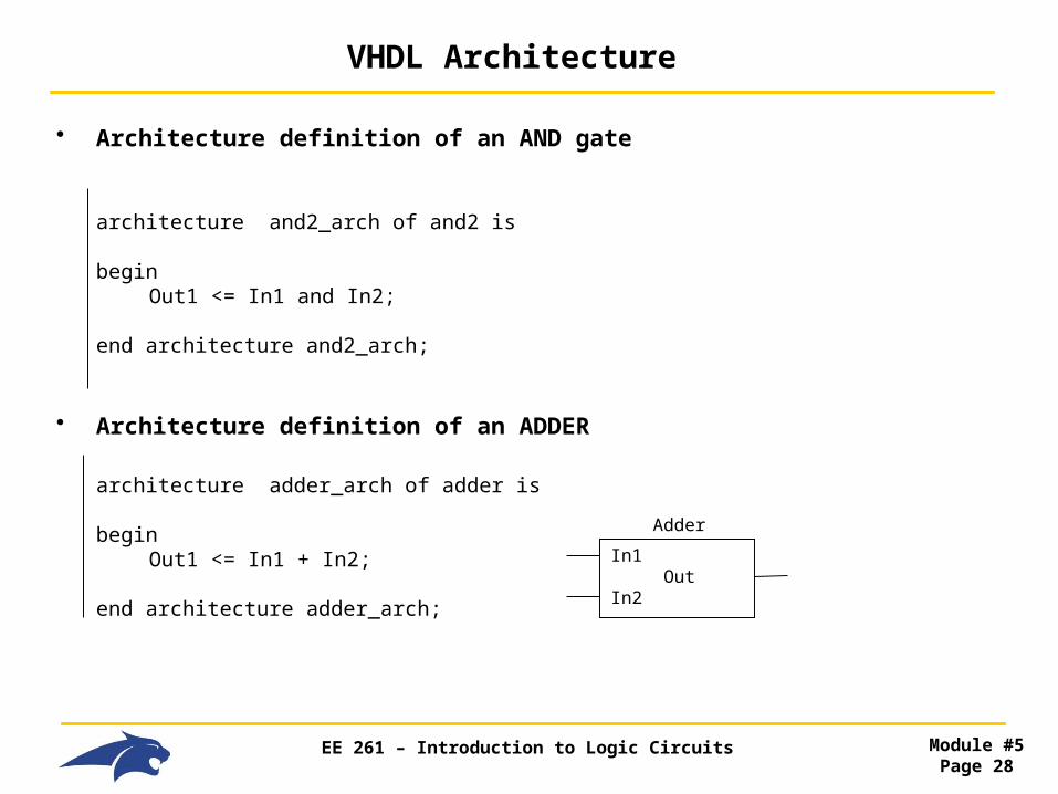
• Architecture definition of an AND gate
architecture and2_arch of and2 is
begin Out1 <= In1 and In2;
end architecture and2_arch;
• Architecture definition of an ADDER
architecture adder_arch of adder is
begin Out1 <= In1 + In2;
end architecture adder_arch;
In1 OutIn2
Adder
EE 261 – Introduction to Logic Circuits Module #5Page 29
VHDL Packages
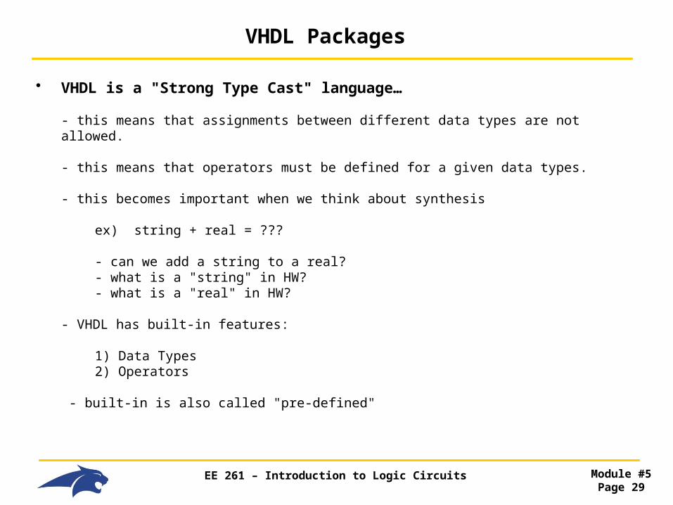
• VHDL is a "Strong Type Cast" language…
- this means that assignments between different data types are not allowed.
- this means that operators must be defined for a given data types.
- this becomes important when we think about synthesis
ex) string + real = ???
- can we add a string to a real? - what is a "string" in HW? - what is a "real" in HW?
- VHDL has built-in features:
1) Data Types 2) Operators
- built-in is also called "pre-defined"

EE 261 – Introduction to Logic Circuits Module #5Page 30
VHDL Packages
• Pre-defined Functionality
ex) there is a built in addition operator for integers
integer + integer = integer
- the built-in operator "+" works for "integers" only - it doesn't work for "bits" as is
• Adding on Functionality
- VHDL allows us to define our own data types and operators- a set of types, operators, functions, procedures… is called a "Package"- A set of packages are kept in a "Library"
EE 261 – Introduction to Logic Circuits Module #5Page 31
VHDL Packages
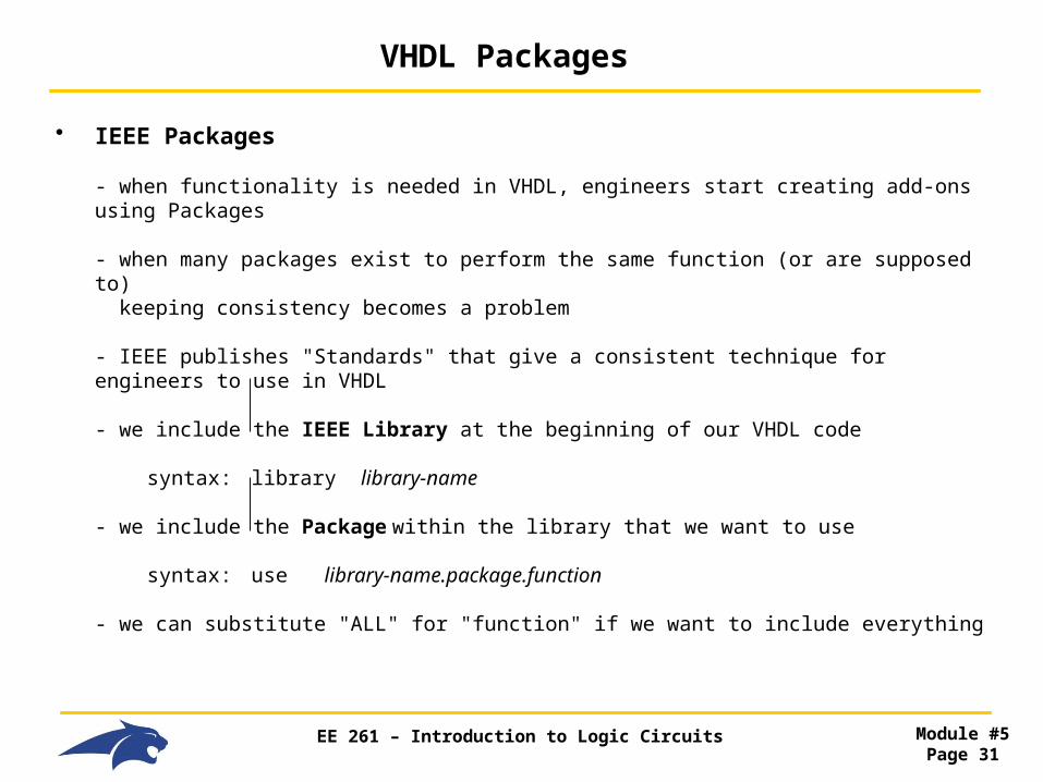
• IEEE Packages
- when functionality is needed in VHDL, engineers start creating add-ons using Packages
- when many packages exist to perform the same function (or are supposed to) keeping consistency becomes a problem
- IEEE publishes "Standards" that give a consistent technique for engineers to use in VHDL
- we include the IEEE Library at the beginning of our VHDL code syntax: library library-name
- we include the Package within the library that we want to use
syntax: use library-name.package.function
- we can substitute "ALL" for "function" if we want to include everything
EE 261 – Introduction to Logic Circuits Module #5Page 32
VHDL Packages
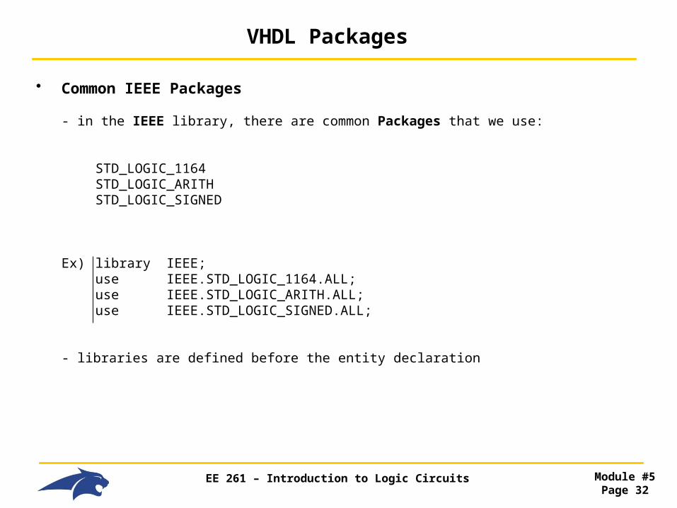
• Common IEEE Packages
- in the IEEE library, there are common Packages that we use:
STD_LOGIC_1164 STD_LOGIC_ARITH STD_LOGIC_SIGNED
Ex) library IEEE; use IEEE.STD_LOGIC_1164.ALL; use IEEE.STD_LOGIC_ARITH.ALL; use IEEE.STD_LOGIC_SIGNED.ALL;
- libraries are defined before the entity declaration

EE 261 – Introduction to Logic Circuits Module #5Page 33
VHDL Design
• Let's Put it all together now…
library IEEE; -- package use IEEE.STD_LOGIC_1164.ALL; use IEEE.STD_LOGIC_ARITH.ALL; use IEEE.STD_LOGIC_SIGNED.ALL;
entity and2 is -- entity declaration
port (In1, In2 : in STD_LOGIC; Out1 : out STD_LOGIC);
end entity and2;
architecture and2_arch of and2 is -- architecture definition
begin Out1 <= In1 and In2;
end architecture and2_arch;
EE 261 – Introduction to Logic Circuits Module #5Page 34
VHDL Design
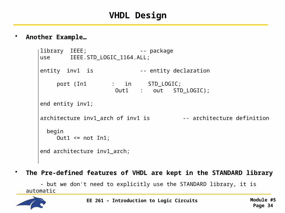
• Another Example…
library IEEE; -- package use IEEE.STD_LOGIC_1164.ALL;
entity inv1 is -- entity declaration
port (In1 : in STD_LOGIC; Out1 : out STD_LOGIC);
end entity inv1;
architecture inv1_arch of inv1 is -- architecture definition
begin Out1 <= not In1;
end architecture inv1_arch;
• The Pre-defined features of VHDL are kept in the STANDARD library
- but we don't need to explicitly use the STANDARD library, it is automatic

EE 261 – Introduction to Logic Circuits Module #5Page 35
VHDL Data Types
• Signals
- a single bit is considered a Scalar quantity
- a bus (or multiple bits represented with one name) is called a Vector
- in VHDL, we can define a signal bus as:
data_bus : in bit_vector (7 downto 0); -- we will use "downto"
or
data_bus : in bit_vector (0 to 7);
- the Most Significant Bit (MSB) is ALWAYS on the left of the range description:
ex) data_bus : in bit_vector (7 downto 0);
data_bus(7) = MSB
ex) data_bus : in bit_vector (0 to 7);
data_bus(0) = MSB

EE 261 – Introduction to Logic Circuits Module #5Page 36
VHDL Data Types
• Signals
- there are "Internal" and "External" signals
Internal - are within the Entity's Interface
External - are outside the Entity's Interface and connect it to other systems

EE 261 – Introduction to Logic Circuits Module #5Page 37
VHDL Data Types
• Scalar Data Types (Built into VHDL)
- scalar means that the type only has one value at any given time
Boolean - values {TRUE, FALSE} - not the same as '0' or '1'
Character - values are all symbols in the 8-bit ISO8859-1 set (i.e., Latin-1) - examples are '0', '+', 'A', 'a', '\'
Integer - values are whole numbers from -2,147,483,647 to +2,147,483,647 - the range comes from +/- 232
- examples are -12, 0, 1002
Real - values are fractional numbers from -1.0E308 to +1.0E308 - examples are 0.0, 1.134, 1.0E5
Bit - values {'0', '1'} - different from Boolean - this type can be used for logic gates - single bits are always represented with single quotes (i.e., '0', '1')

EE 261 – Introduction to Logic Circuits Module #5Page 38
VHDL Data Types
• Array Data Types (Built into VHDL)
- array is a name that represents multiple signals
Bit_Vector - vector of bits, values {'0', '1'} - array values are represented with double quotes (i.e., "0010") - this type can be used for logic gates
ex) Addr_bus : in BIT_VECTOR (7 downto 0);
- unlimited range - first element of array has index=0 (i.e., Addr_bus(0)…)
String - vector of characters, values{Latin-1} - again use double quotes - define using "to" or "downto" ("to" is easier for strings) ex) Message : string (1 to 10) := "message here…"
- first element in array has index=1, this is different from BIT_VECTOR

EE 261 – Introduction to Logic Circuits Module #5Page 39
VHDL Data Types
• Physical Data Types (Built into VHDL)
- these types contain object value and unites- NOT synthesizable
Time - range from -2,147,483,647 to +2,147,483,647 - units: fs, ps, ns, us, ms, sec, min, hr
• User-Defined Enumerated Types
- we can create our own descriptive types, useful for State Machine- no quotes needed
ex) type States is (Red, Yellow, Green);

EE 261 – Introduction to Logic Circuits Module #5Page 40
VHDL Operators
• VHDL Operators
- Data types define both "values" and "operators"
- There are "Pre-Determined" data types
Pre-determined = Built-In = STANDARD Package
- We can add additional types/operators by including other Packages
- We'll first start with the STANDARD Package that comes with VHDL
EE 261 – Introduction to Logic Circuits Module #5Page 41
VHDL Operators
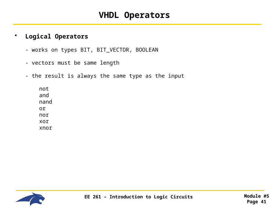
• Logical Operators
- works on types BIT, BIT_VECTOR, BOOLEAN
- vectors must be same length
- the result is always the same type as the input
not and nand or nor xor xnor
EE 261 – Introduction to Logic Circuits Module #5Page 42
VHDL Operators
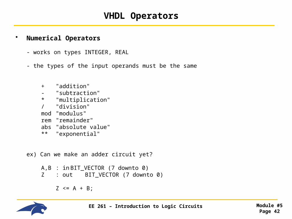
• Numerical Operators
- works on types INTEGER, REAL
- the types of the input operands must be the same
+ "addition" - "subtraction" * "multiplication" / "division" mod "modulus" rem "remainder" abs "absolute value" ** "exponential"
ex) Can we make an adder circuit yet?
A,B : in BIT_VECTOR (7 downto 0) Z : out BIT_VECTOR (7 downto 0)
Z <= A + B;
EE 261 – Introduction to Logic Circuits Module #5Page 43
VHDL Operators
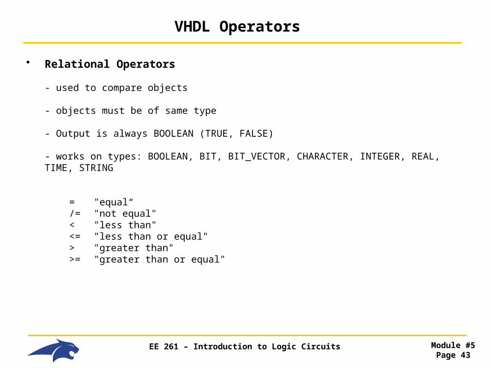
• Relational Operators
- used to compare objects
- objects must be of same type
- Output is always BOOLEAN (TRUE, FALSE)
- works on types: BOOLEAN, BIT, BIT_VECTOR, CHARACTER, INTEGER, REAL, TIME, STRING
= "equal“ /= "not equal" < "less than" <= "less than or equal" > "greater than" >= "greater than or equal"

EE 261 – Introduction to Logic Circuits Module #5Page 44
VHDL Operators
• Shift Operators
- works on one-dimensional arrays
- works on arrays that contain types BIT, BOOLEAN
- the operator requires 1) An Operand (what is to be shifted) 2) Number of Shifts (specified as an INTEGER)
- a negative Number of Shifts (i.e., "-") is valid and reverses the direction of the shift
sll "shift left logical" srl "shift right logical" sla "shift left arithmetic" sra "shift right arithmetic" rol "rotate left" ror "rotate right"
EE 261 – Introduction to Logic Circuits Module #5Page 45
VHDL Operators
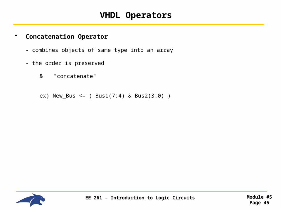
• Concatenation Operator
- combines objects of same type into an array
- the order is preserved
& "concatenate"
ex) New_Bus <= ( Bus1(7:4) & Bus2(3:0) )

EE 261 – Introduction to Logic Circuits Module #5Page 46
VHDL Operators
• Assignment Operators
- The assignment operator is <=
- The Results is always on the Left, Operands on the Right
- Types need to all be of the same type
- need to watch the length of arrays!
Ex) x <= y;
a <= b or c;
sum <= x + y;
NewBus <= m & k;

EE 261 – Introduction to Logic Circuits Module #5Page 47
VHDL Operators
• Delay Modeling
- VHDL allows us to include timing information into assignment statements
- this gives us the ability to model real world gate delay
- we use the keyword "after" in our assignment followed by a time operand.
Ex) B <= not A after 2ns;
- VHDL has two types of timing models that allow more accurate representation of real gates
1) Inertial Delay (default) 2) Transport Delay
EE 261 – Introduction to Logic Circuits Module #5Page 48
VHDL Operators
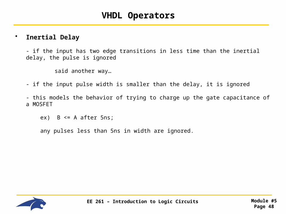
• Inertial Delay
- if the input has two edge transitions in less time than the inertial delay, the pulse is ignored
said another way…
- if the input pulse width is smaller than the delay, it is ignored
- this models the behavior of trying to charge up the gate capacitance of a MOSFET
ex) B <= A after 5ns;
any pulses less than 5ns in width are ignored.

EE 261 – Introduction to Logic Circuits Module #5Page 49
VHDL Operators
• Transport Delay
- transport delay will always pass the pulse, no matter how small it is.
- this models the behavior of transmission lines
- we have to explicitly call out this type of delay using the "transport" keyword
ex) B <= transport A after 5ns;
B <= transport not A after t_delay; -- here we used a constant

EE 261 – Introduction to Logic Circuits Module #5Page 50
VHDL Structural Design
• Structural Design
- we can specify functionality in an architecture in two ways
1) Structurally : text based schematic, manual instantiation of another system
2) Behaviorally : abstract description of functionality
- we will start with learning Structural VHDL design
• Components
- blocks that already exist and are included into a higher level design
- we need to know the entity declaration of the system we are calling
- we "declare" a component using the keyword "component"
- we declare the component in the architecture which indicates we wish to use it

EE 261 – Introduction to Logic Circuits Module #5Page 51
VHDL Structural Design
• Component Syntax
component component-name
port (signal-name : mode signal-type; signal-name : mode signal-type); -- exactly the same as the Entity declaration
end component;
• Let's build this…

EE 261 – Introduction to Logic Circuits Module #5Page 52
VHDL Structural Design
• Component Example
- let's use these pre-existing entities "xor2" & "or2"
entity xor2 is
port (In1, In2 : in STD_LOGIC; Out1 : out STD_LOGIC);
end entity xor2;
entity or2 is
port (In1, In2 : in STD_LOGIC; Out1 : out STD_LOGIC);
end entity or2;

EE 261 – Introduction to Logic Circuits Module #5Page 53
VHDL Structural Design
• Component Example
- now let's include the pre-existing entities "xor2" & "or2" into our "TOP" design
entity TOP is port (A,B,C : in STD_LOGIC; X : out STD_LOGIC); end entity TOP;
architecture TOP_arch of TOP is
component xor2 -- declaration of xor2 component port (In1, In2 : in STD_LOGIC; Out1 : out STD_LOGIC); end component;
entity or2 is -- declaration of or2 component port (In1, In2 : in STD_LOGIC;
Out1 : out STD_LOGIC); end component;
begin …..
EE 261 – Introduction to Logic Circuits Module #5Page 54
VHDL Structural Design
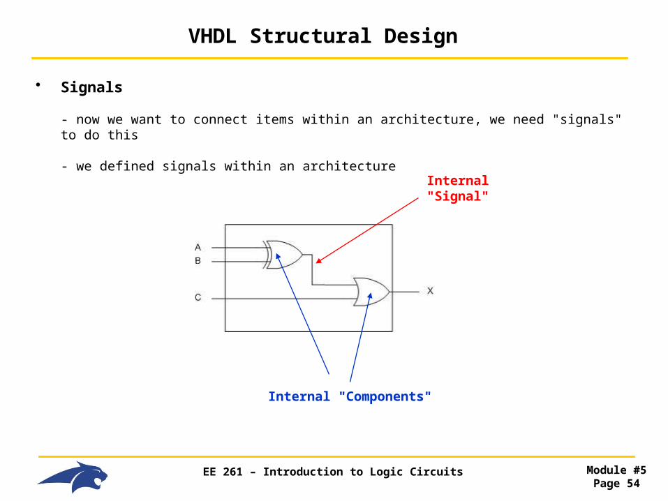
• Signals
- now we want to connect items within an architecture, we need "signals" to do this
- we defined signals within an architecture
Internal "Signal"
Internal "Components"
EE 261 – Introduction to Logic Circuits Module #5Page 55
VHDL Structural Design
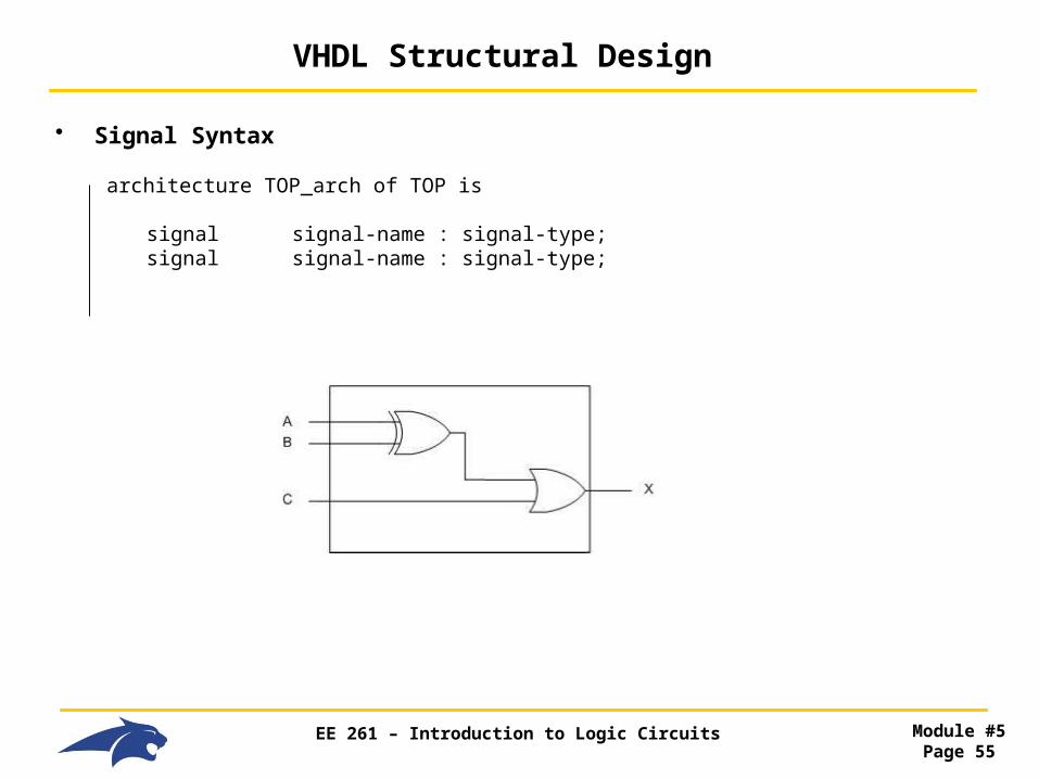
• Signal Syntax
architecture TOP_arch of TOP is
signal signal-name : signal-type; signal signal-name : signal-type;
EE 261 – Introduction to Logic Circuits Module #5Page 56
VHDL Structural Design
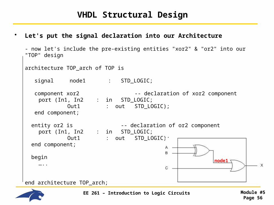
• Let's put the signal declaration into our Architecture
- now let's include the pre-existing entities "xor2" & "or2" into our "TOP" design
architecture TOP_arch of TOP is
signal node1 : STD_LOGIC;
component xor2 -- declaration of xor2 component port (In1, In2 : in STD_LOGIC; Out1 : out STD_LOGIC); end component;
entity or2 is -- declaration of or2 component port (In1, In2 : in STD_LOGIC;
Out1 : out STD_LOGIC); end component;
begin …..
end architecture TOP_arch;
node1
EE 261 – Introduction to Logic Circuits Module #5Page 57
VHDL Structural Design
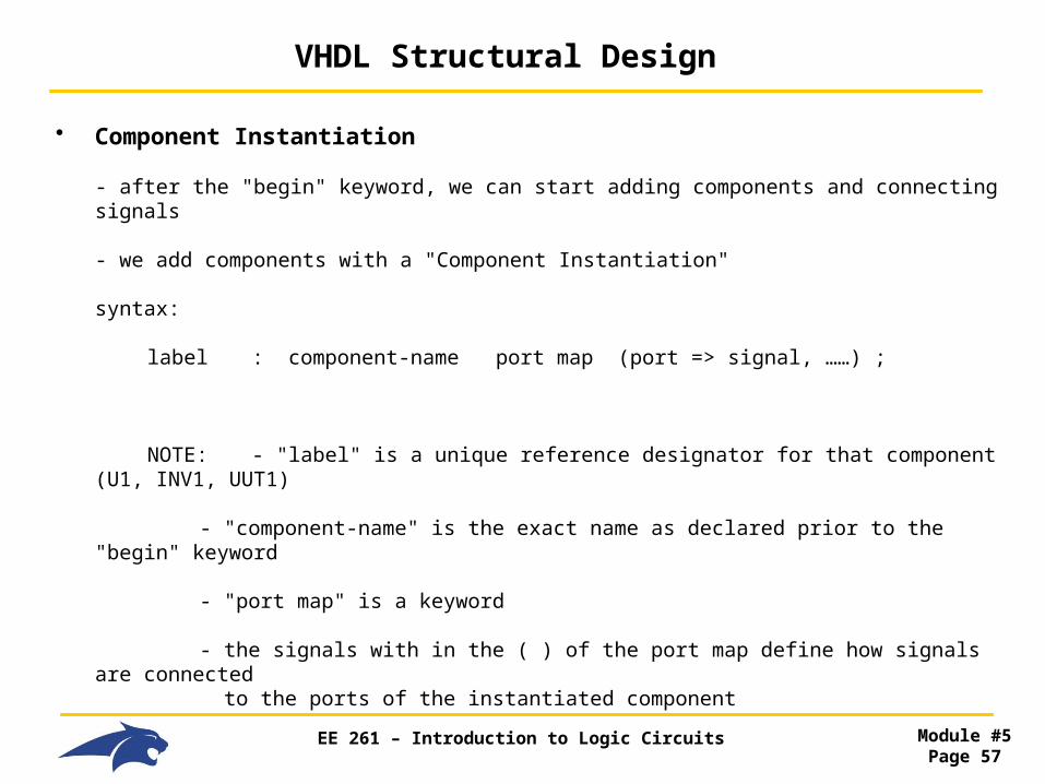
• Component Instantiation
- after the "begin" keyword, we can start adding components and connecting signals
- we add components with a "Component Instantiation"
syntax:
label : component-name port map (port => signal, ……) ;
NOTE: - "label" is a unique reference designator for that component (U1, INV1, UUT1)
- "component-name" is the exact name as declared prior to the "begin" keyword
- "port map" is a keyword
- the signals with in the ( ) of the port map define how signals are connected to the ports of the instantiated component
EE 261 – Introduction to Logic Circuits Module #5Page 58
VHDL Structural Design
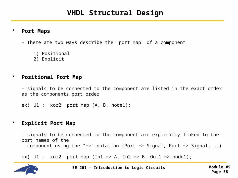
• Port Maps
- There are two ways describe the "port map" of a component
1) Positional 2) Explicit
• Positional Port Map
- signals to be connected to the component are listed in the exact order as the components port order
ex) U1 : xor2 port map (A, B, node1);
• Explicit Port Map
- signals to be connected to the component are explicitly linked to the port names of the component using the "=>" notation (Port => Signal, Port => Signal, ….)
ex) U1 : xor2 port map (In1 => A, In2 => B, Out1 => node1);
EE 261 – Introduction to Logic Circuits Module #5Page 59
VHDL Structural Design
• Execution
- All components are executed CONCURRENTLY
- this mimics real hardware
- this is different from traditional program execution (i.e., C/C++) which is executed sequentially because
We are NOT writing code, we are describing hardware!!!

EE 261 – Introduction to Logic Circuits Module #5Page 60
VHDL Structural Design
• Let's put everything together
architecture TOP_arch of TOP is
signal node1 : STD_LOGIC;
component xor2 -- declaration of xor2 component port (In1, In2 : in STD_LOGIC; Out1 : out STD_LOGIC); end component;
component or2 is -- declaration of or2 component port (In1, In2 : in STD_LOGIC;
Out1 : out STD_LOGIC); end component;
begin U1 : xor2 port map (In1=>A, In2=>B, Out1=>node1); U2 : or2 port map (In1=>C, In2=>node1, Out1=>X);
end architecture TOP_arch;
node1U1
U2

EE 261 – Introduction to Logic Circuits Module #5Page 61
VHDL Concurrent Signal Assignments
• Concurrency
- the way that our designs are simulated is important in modeling real HW behavior
- components are executed concurrently (i.e., at the same time)
- VHDL gives us another method to describe concurrent logic behavior called
"Concurrent Signal Assignments"
- we simply list our signal assignments (<=) after the "begin" statement in the architecture
- each time any signal on the Right Hand Side (RHS) of the expression changes, the Left Hand Side (LHS) of the assignment is updated.
- operators can be included (and, or, +, …)

EE 261 – Introduction to Logic Circuits Module #5Page 62
VHDL Concurrent Signal Assignments
• Concurrent Signal Assignment Example
entity TOP is port (A,B,C : in STD_LOGIC; X : out STD_LOGIC); end entity TOP;
architecture TOP_arch of TOP is
signal node1 : STD_LOGIC; begin
node1 <= A xor B; X <= node1 or C;
end architecture TOP_arch;
node1

EE 261 – Introduction to Logic Circuits Module #5Page 63
VHDL Concurrent Signal Assignments
• Concurrent Signal Assignment Example
node1 <= A xor B; X <= node1 or C;
- if these are executed concurrently, does it model the real behavior of this circuit?
Yes, that is how these gates operate. We can see that there may be timing that needs to be considered….
- When does C get to the OR gate relative to (A B)? - Could this cause a glitch on X? What about a delay in the actual value?
node1

EE 261 – Introduction to Logic Circuits Module #5Page 64
VHDL Concurrent Signal Assignments
• Conditional Signal Assignments
- we can also include conditional situations in a concurrent assignment
- the keywords for these are:
"when" = if the condition is TRUE, make this assignment "else" = if the condition is FALSE, make this assignment
ex) X <= '1' when A='0' else '0'; Y <= '0' when A='0' and C='0' else '1';
- X and Y are evaluated concurrently !!!
- notice that we are assigning static values (0 and 1), this is essentially a "Truth Table"
- if using this notation, make sure to include every possible input condition, or else you haven't described the full operation of the circuit.

EE 261 – Introduction to Logic Circuits Module #5Page 65
VHDL Concurrent Signal Assignments
• Conditional Signal Assignments
- We can also assign signals to other signals using conditions
- this is similar to a MUX
ex) X <= A when Sel='0' else B;
- Again, make sure to include every possible input condition, or else you haven't described the full operation of the circuit.
- If you try to synthesis an incomplete description, the tool will start making stuff up!
EE 261 – Introduction to Logic Circuits Module #5Page 66
VHDL Concurrent Signal Assignments
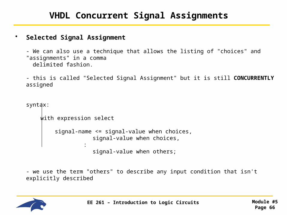
• Selected Signal Assignment
- We can also use a technique that allows the listing of "choices" and "assignments" in a comma delimited fashion.
- this is called "Selected Signal Assignment" but it is still CONCURRENTLY assigned
syntax:
with expression select
signal-name <= signal-value when choices, signal-value when choices, : signal-value when others;
- we use the term "others" to describe any input condition that isn't explicitly described
EE 261 – Introduction to Logic Circuits Module #5Page 67
VHDL Concurrent Signal Assignments
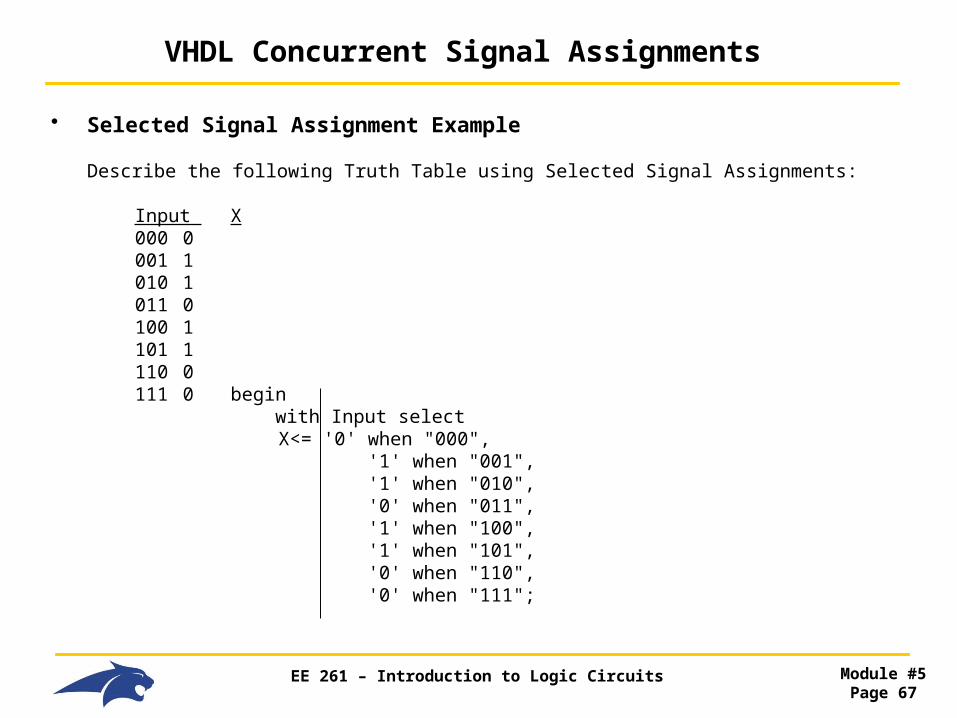
• Selected Signal Assignment Example
Describe the following Truth Table using Selected Signal Assignments:
Input X 000 0 001 1 010 1 011 0 100 1 101 1 110 0 111 0 begin
with Input select X<= '0' when "000", '1' when "001", '1' when "010", '0' when "011", '1' when "100", '1' when "101", '0' when "110", '0' when "111";

EE 261 – Introduction to Logic Circuits Module #5Page 68
VHDL Concurrent Signal Assignments
• Selected Signal Assignment Example
- we can shorten the description by using "others" for the 0's
- we can also use "|" delimited choices
Input X 000 0 001 1 010 1 011 0 100 1 101 1 110 0 111 0 begin
with Input select X<= '1' when "001" | "010" | "100" | "101",
'0' when others;

EE 261 – Introduction to Logic Circuits Module #5Page 69
Decoder Example using Structural VHDL
• Decoders
- a decoder has n inputs and 2n outputs
- one and only one output is asserted for a given input combination
ex) truth table of decoder
Input Output 00 0001 01 0010 10 0100 11 1000
- these are key circuits for a Address Decoders

EE 261 – Introduction to Logic Circuits Module #5Page 70
Decoder Example using Structural VHDL
• Decoder Structure
- The output stage of a decoder can be constructed using AND gates- Inverters are needed to give the appropriate code to each AND gate- Using AND/INV structure, we need:
2n AND gates n Inverters
Showing more inverters than necessary to illustrate concept

EE 261 – Introduction to Logic Circuits Module #5Page 71
Decoder Example using Structural VHDL
• Decoders with ENABLES
- An Enable line can be fed into the AND gate
- The AND gate now needs (n+1) inputs
- Using positive logic:
EN = 0, Output = 0 EN =1, Output depends on input code
EE 261 – Introduction to Logic Circuits Module #5Page 72
Decoder Example using Structural VHDL
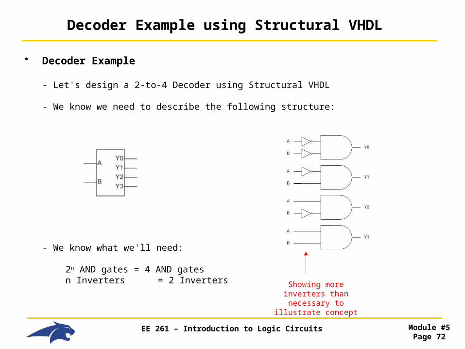
• Decoder Example
- Let's design a 2-to-4 Decoder using Structural VHDL
- We know we need to describe the following structure:
- We know what we'll need:
2n AND gates = 4 AND gates n Inverters = 2 Inverters Showing more inverters
than necessary to illustrate concept
EE 261 – Introduction to Logic Circuits Module #5Page 73
Decoder Example using Structural VHDL
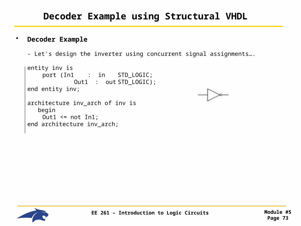
• Decoder Example
- Let's design the inverter using concurrent signal assignments….
entity inv is port (In1 : in STD_LOGIC; Out1 : out STD_LOGIC); end entity inv;
architecture inv_arch of inv is begin Out1 <= not In1; end architecture inv_arch;

EE 261 – Introduction to Logic Circuits Module #5Page 74
Decoder Example using Structural VHDL
• Decoder Example
- Let's design the AND gate using concurrent signal assignments….
entity and2 is port (In1,In2 : in STD_LOGIC; Out1 : out STD_LOGIC); end entity and2;
architecture and2_arch of and2 is begin Out1 <= In1 and In2; end architecture and2_arch;
EE 261 – Introduction to Logic Circuits Module #5Page 75
Decoder Example using Structural VHDL
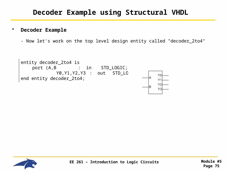
• Decoder Example
- Now let's work on the top level design entity called "decoder_2to4"
entity decoder_2to4 is port (A,B : in STD_LOGIC; Y0,Y1,Y2,Y3 : out STD_LOGIC); end entity decoder_2to4;

EE 261 – Introduction to Logic Circuits Module #5Page 76
Decoder Example using Structural VHDL
• Decoder Example
- Now let's work on the top level design architecture called "decoder_2to4_arch"
architecture decoder_2to4 _arch of decoder_2to4 is
signal A_n, B_n : STD_LOGIC;
component inv port (In1 : in STD_LOGIC; Out1 : out STD_LOGIC); end component;
component and2 port (In1,In2 : in STD_LOGIC; Out1 : out STD_LOGIC); end component;
begin ………

EE 261 – Introduction to Logic Circuits Module #5Page 77
Decoder Example using Structural VHDL
• Decoder Example
- cont….
begin U1 : inv port map (A, A_n); U2 : inv port map (B, B_n);
U3 : and2 port map (A_n, B_n, Y0); U4 : and2 port map (A, B_n, Y1); U5 : and2 port map (A_n, B, Y2); U6 : and2 port map (A, B, Y3);
end architecture decoder_2to4 _arch;