INTRODUCTION TO COMPUTER SYSTEMS 2 1.1. DEFINITION...
75
Introduction to computers Derrick H.O.Osiro. TUK 1 1.0 INTRODUCTION TO COMPUTER SYSTEMS ................................................... 2 1.1. DEFINITION/TERMINOLOGIES...................................................................... 2 1.2 DIGITAL VS ANALOGUE ................................................................................ 4 1.3 DIGITAL NUMBER SYSTEM ........................................................................... 7 1.4 OCTAL NUMBER SYSTEM............................................................................ 11 1.5 HEXADECIMAL NUMBER SYSTEM............................................................ 12 1.6 BYTE PREFIXES .............................................................................................. 13 2.0 ELEMENTS OF A COMPUTER SYSTEM ......................................................... 15 2.1 HISTORY OF COMPUTERS ........................................................................... 16 2.2 COMPUTER GENERATIONS ......................................................................... 17 2.3 TYPES OF COMPUTERS ................................................................................ 28 2.4 CLASSIFICATION OF DIGITAL COMPUTER ................................................ 29 3.0 COMPUTER COMPONENTS AND THEIR FUNCTIONS ............................... 33 3.1 MAIN PROCESSOR (OR CENTRAL PROCESSING UNIT, CPU). .............. 33 3.2 INPUT UNIT...................................................................................................... 36 3.3 OUTPUT UNIT.................................................................................................. 56 3.4 MEMORY [STORAGE DEVICES] ................................................................. 66 3.5 THE SYSTEM UNIT ......................................................................................... 73 REFERENCES ............................................................................................................. 75
Transcript of INTRODUCTION TO COMPUTER SYSTEMS 2 1.1. DEFINITION...

Introduction to computers
Derrick H.O.Osiro. TUK 1
1.0 INTRODUCTION TO COMPUTER SYSTEMS ................................................... 2
1.1. DEFINITION/TERMINOLOGIES ...................................................................... 2
1.2 DIGITAL VS ANALOGUE ................................................................................ 4
1.3 DIGITAL NUMBER SYSTEM ........................................................................... 7
1.4 OCTAL NUMBER SYSTEM ............................................................................ 11
1.5 HEXADECIMAL NUMBER SYSTEM ............................................................ 12
1.6 BYTE PREFIXES .............................................................................................. 13
2.0 ELEMENTS OF A COMPUTER SYSTEM ......................................................... 15
2.1 HISTORY OF COMPUTERS ........................................................................... 16
2.2 COMPUTER GENERATIONS ......................................................................... 17
2.3 TYPES OF COMPUTERS ................................................................................ 28
2.4 CLASSIFICATION OF DIGITAL COMPUTER ................................................ 29
3.0 COMPUTER COMPONENTS AND THEIR FUNCTIONS ............................... 33
3.1 MAIN PROCESSOR (OR CENTRAL PROCESSING UNIT, CPU). .............. 33
3.2 INPUT UNIT. ..................................................................................................... 36
3.3 OUTPUT UNIT .................................................................................................. 56
3.4 MEMORY [STORAGE DEVICES] ................................................................. 66
3.5 THE SYSTEM UNIT ......................................................................................... 73
REFERENCES ............................................................................................................. 75

Introduction to computers
Derrick H.O.Osiro. TUK 2
1.0 INTRODUCTION TO COMPUTER SYSTEMS 1.1. DEFINITION/TERMINOLOGIES (a) Digital Computer
A computer is a Programmable digital electronic device that can store, retrieve, process
data and display the processed data (information)
Or
A computer is a device which works under the control of stored instructions (programs),
automatically accepting and processing data to produce information (that is the result of
that processing).
Or
A computer is an electronic device, operating under the control of instructions stored in
its own memory that can accept data (input), manipulate the data according to specified
rules (processes), produce results (output), and store the results for future use.
(b) Data
Data is input from user or other sources. It may be numbers, text, sound, images, etc. may
be unintelligible (i.e. unrecognizable), may be commands or instructions
Or
Data is a collection of un-organized facts, which can include words, numbers. Images,
and sounds. Computers manipulate and process data to create information.
(c) Information
Information is the output from the computer. It is formatted and understandable, can be
printed text, graphics, images, sounds or video.
Or
Information is data that is organized, has meaning, and is useful. Examples are reports,
newsletters, a receipt, a picture, an invoice, or a check. Data is processed and
manipulated to create a check.
Data entered into a computer is called input. The processed results are called output.
Thus, a computer processes input to create output. A computer also can hold data and
information for future use in an area called storage. This cycle of input, process, output,
and storage is called the information processing cycle.

Introduction to computers
Derrick H.O.Osiro. TUK 3
(d) Hardware
Hardware is the physical (the electric, electronic, and mechanical) components of the
computer. These include processor, motherboard, memory, drives, video/sound cards etc.
(e) Instruction
Instruction is a command in binary that is recognized and executed by the computer to
accomplish task.
(f) Program
A program is the set of instructions written for the computer to perform a task. A group
of programs is called software.
(g) Software
Software is the series of instruction that tells the hardware how to perform tasks. Without
software, hardware is useless; hardware needs the instructions provided by software to
process data into information
(h) Firmware
Firmware are programs (set of instructions) that sit on a microchip in hardware (i.e. are
programs stored in hardware e.g. in ROM).They are often used to start up (i.e. boot) the
machine. It keeps settings such as "bios” (i.e., configuration) system settings
(i) Liveware
A person that communicates with a computer or uses the information it generates is
called a user (live ware).
(j) Peripherals:
Computer peripherals are the term used to describe all the elements connected to the
computer apart from the computer itself. These are the facilities/equipments connected to
the computer to assist the computers in satisfying its users.

Introduction to computers
Derrick H.O.Osiro. TUK 4
1.2 DIGITAL VS ANALOGUE
1.2.1 Numerical Presentation In science, technology, business, and, in fact, most other fields of endeavour, we are
constantly dealing with quantities. Quantities are measured, monitored, recorded,
manipulated arithmetically, observed, or in some other way utilized in most physical
systems. It is important when dealing with various quantities that we be able to represent
their values efficiently and accurately. There are basically two ways of representing the
numerical value of quantities: analog and digital.
1.2.2 Analog Representation In analog representation a quantity is represented by a voltage, current, or meter
movement that is proportional to the value of that quantity. Analog quantities such as
those cited above have an important characteristic: they can vary over a continuous range
of values.
The following is a diagram of analog voltage vs time:
Figure 1.1.analogue waveform
1.2.3 Digital Representation In digital representation the quantities are represented not by proportional quantities but
by symbols called digits. As an example, consider the digital watch, which provides the
time of day in the form of decimal digits which represent hours and minutes (and
Introduction to computers
Derrick H.O.Osiro. TUK 5
sometimes seconds). As we know, the time of day changes continuously, but the digital
watch reading does not change continuously; rather, it changes in steps of one per minute
(or per second). In other words, this digital representation of the time of day changes in
discrete steps, as compared with the representation of time provided by an analog watch,
where the dial reading changes continuously.
Digital quantities are represented using digits
The following is a diagram of digital voltage vs time:
Figure 1.2. Digital waveform The major difference between analog and digital quantities, then, can be simply stated as
follows:
Analog = changes continuously
Digital = changes in discrete steps (step by step)
1.2.4 Advantages and Limitations of Digital Techniques (i) Advantages
Easier to design. Exact values of voltage or current are not important, only the
range (HIGH or LOW) in which they fall.
Information storage is easy.
Accuracy and precision are greater.
Operation can be programmed. Analog systems can also be programmed, but the
variety and complexity of the available operations is severely limited.

Introduction to computers
Derrick H.O.Osiro. TUK 6
Digital circuits are less affected by noise. As long as the noise is not large enough
to prevent us from distinguishing a HIGH from a LOW.
More digital circuitry can be fabricated on IC chips.
(ii) Limitations
There is really only one major drawback when using digital techniques:
The real world is mainly analog.
Most physical quantities are analog in nature, and it is these quantities that are often the
inputs and outputs that are being monitored, operated on, and controlled by a system.
To take advantage of digital techniques when dealing with analog inputs and outputs,
three steps must be followed:
1. Convert the real-world analog inputs to digital form. (ADC)
2. Process (operate on) the digital information.
3. Convert the digital outputs back to real-world analog form. (DAC)
The following diagram shows a temperature control system that requires analog/digital
conversions in order to allow the use of digital processing techniques.
Figure 1.3. Signal conversion
Introduction to computers
Derrick H.O.Osiro. TUK 7
1.3 DIGITAL NUMBER SYSTEM Many number systems are in use in digital technology. The most common are the
decimal, binary, octal, and hexadecimal systems. The decimal system is clearly the most
familiar to us because it is a tool that we use every day. Examining some of its
characteristics will help us to better understand the other systems.
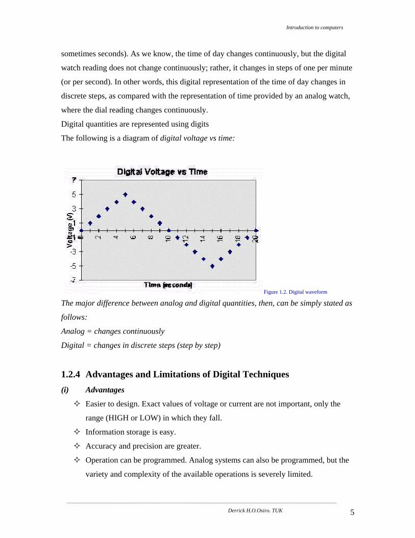
1.3.1 Decimal System Decimal System The decimal system is composed of 10 numerals or symbols. These 10
symbols are 0, 1, 2, 3, 4, 5, 6, 7, 8, and 9; using these symbols as digits of a number, we
can express any quantity. The decimal system, also called the base-10 system because it
has 10 digits.
103 102 101 100 10-1 10-2 10-3
=1000 =100 =10 =1 . =0.1 =0.01 =0.001
Most
Significant
Digit
Decimal
point
Least
Significant
Digit
1.3.2 Binary System In the binary system, there are only two symbols or possible digit values, 0 and 1. This
base-2 system can be used to represent any quantity that can be represented in decimal or
other number system.
23 22 21 20 2-1 2-2 2-3
=8 =4 =2 =1 . =1/2 =1/4 =1/8
Most
Significant
Bit
Binary
point
Least
Significant
Bit

Introduction to computers
Derrick H.O.Osiro. TUK 8
1.3.3 Binary Counting The Binary counting sequence is shown in the table:
23=8 22=4 21=2 20=1 Decimal Equivalent
0 0 0 0 0
0 0 0 1 1
0 0 1 0 2
0 0 1 1 3
0 1 0 0 4
0 1 0 1 5
0 1 1 0 6
0 1 1 1 7
1 0 0 0 8
1 0 0 1 9
1 0 1 0 10
1 0 1 1 11
1 1 0 0 12
1 1 0 1 13
1 1 1 0 14
1 1 1 1 15
1.3.4 Representing Binary Quantities In digital systems the information that is being processed is usually presented in binary
form. Binary quantities can be represented by any device that has only two operating
states or possible conditions. E.g. a switch has only open or closed. We arbitrarily (as we
define them) let an open switch represent binary 0 and a closed switch represent binary 1.
Thus we can represent any binary number by using series of switches.
Typical Voltage Assignment
Binary 1: Any voltage between 2.4V to 5V
Binary 0: Any voltage between 0V to 0.8V
Not used: Voltage between 0.8V to 2V, this may cause error in a digital circuit
Introduction to computers
Derrick H.O.Osiro. TUK 9
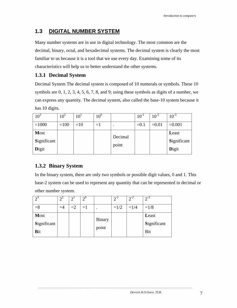
Figure 1.4. Binary signal We can see another significant difference between digital and analog systems. In digital
systems, the exact value of a voltage is not important; e.g., a voltage of 3.6V means the
same as a voltage of 4.3V. In analog systems, the exact value of a voltage is important.
(a) Binary-To-Decimal Conversion Any binary number can be converted to its decimal equivalent simply by summing
together the weights of the various positions in the binary number which contain a 1.
1 1 0 1 1 2 (binary)
24+23+0+21+20 = 16+8+0+2+1
= 2710 (decimal) And
1 0 1 1 0 1 0 1 2 (binary)
27+0+25+24+0+22+0+20 = 128+0+32+16+0+4+0+1
= 18110 (decimal)
You should noticed the method is find the weights (i.e., powers of 2) for each bit position
that contains a 1, and then to add them up.
(b) Decimal-To-Binary Conversion There are 2 methods:
(i) Reverse of Binary-To-Digital Method
45 10 = 32 + 0 + 8 + 4 +0 + 1
= 25+0+23+22+0+20
= 1 0 1 1 0 12

Introduction to computers
Derrick H.O.Osiro. TUK 10
(ii) Repeat Division This method uses repeated division by 2. Eg. convert 2510 to binary
25/ 2 = 12+ remainder of 1 1 (Least Significant Bit)
12/ 2 = 6 + remainder of 0 0
6 / 2 = 3 + remainder of 0 0
3 / 2 = 1 + remainder of 1 1
1 / 2 = 0 + remainder of 1 1 (Most Significant Bit)
Result 2510 = 1 1 0 0 12
The Flow chart for repeated-division method is as follow:
Figure 1.5. binary conversion

Introduction to computers
Derrick H.O.Osiro. TUK 11
1.4 OCTAL NUMBER SYSTEM The octal number system has a base of eight, meaning that it has eight possible digits: 0,
1,2,3,4,5,6,7.
83 82 81 80 8-1 8-2 8-3
=512 =64 =8 =1 . =1/8 =1/64 =1/512
Most
Significant
Digit
Octal
point
Least
Significant
Digit
(a) Octal to Decimal Conversion
e.g. 24.68 = 2 x (81) + 4 x (80) + 6 x (8-1) = 20.7510
(b) Binary-To-Octal / Octal-To-Binary Conversion
Octal Digit 0 1 2 3 4 5 6 7
Binary
Equivalent 000 001 010 011 100 101 110 111
Each Octal digit is represented by three bits of binary digit.
e.g. 100 111 0102 = (100) (111) (010)2 = 4 7 28
(c) Repeat Division
This method uses repeated division by 8. E.g. convert 17710 to octal and binary:
177/8 = 22+ remainder of 1 1 (Least Significant
Bit) 22/ 8 = 2 + remainder of 6 6
2 / 8 = 0 + remainder of 2 2 (Most Significant
Bit) Result 17710 = 2618
Convert to Binary = 0101100012

Introduction to computers
Derrick H.O.Osiro. TUK 12
1.5 HEXADECIMAL NUMBER SYSTEM The hexadecimal system uses base 16. Thus, it has 16 possible digit symbols. It uses the
digits 0 through 9 plus the letters A, B, C, D, E, and F as the 16 digit symbols
163 162 161 160 16-1 16-2 16-3
=4096 =256 =16 =1 . =1/16 =1/256 =1/4096
Most
Significant
Digit
Hexadec. point
Least
Significant
Digit
(a) Hexadecimal to Decimal Conversion
e.g. 2AF16 = 2 x (162) + 10 x (161) + 15 x (160) = 68710
Repeat Division: Convert decimal to hexadecimal
This method uses repeated division by 16. Eg. convert 37810 to hexadecimal and binary 378/16 = 23+ remainder of 10 A (Least Significant Bit) 23/ 16 = 1 + remainder of 7 7
1 / 16 = 0 + remainder of 1 1 (Most Significant Bit) Result 37810 = 17A8
Convert to Binary = 0001 0111 10102
= 0000 0001 0111 1010 (16 bits)
(b) Binary-To-Hexadecimal / Hexadecimal-To-Binary Conversion
Hexadecimal Digit 0 1 2 3 4 5 6 7
Binary Equivalent 0000 0001 0010 0011 0100 0101 0110 0111
Hexadecimal Digit 8 9 A B C D E F
Binary Equivalent 1000 1001 1010 1011 1100 1101 1110 1111
Each Hexadecimal digit is represented by four bits of binary digit.
e.g. 1011 0010 11112 = (1011) (0010) (1111)2 = B 2 F16
(c) Octal-To-Hexadecimal /Hexadecimal-To-Octal Conversion
(1) Convert Octal (Hexadecimal) to Binary first.

Introduction to computers
Derrick H.O.Osiro. TUK 13
(2a) Regroup the binary number in 3 bits a group starts from the LSB if Octal is
required.
(2b) Regroup the binary number in 4 bits a group from the LSB if Hexadecimal is
required.
eg. Convert 5A816 to Octal.
5A816 = 0101 1010 1000 (Binary)
= 2 6 5 0 (Octal)
1.6 BYTE PREFIXES When one start talking about lots of bytes, the person get into prefixes like kilo, mega and
giga, as in kilobyte, megabyte and gigabyte (also shortened to K, M and G, as in Kbytes,
Mbytes and Gbytes or KB, MB and GB). In bits they becomes Kbits (Kb), Mega Bits
(Mb) etc The following table shows the binary multipliers:
Bit is short form for binary digit (a 0 or a 1). Nibble is a group of 4 bits.
Byte is a group of 8 bits. Kilobit is 1024 (210) bits.
Name Abbr. Size
Kilo K 210 = 1,024
Mega M 220 = 1,048,576
Giga G 230 = 1,073,741,824
Tera T 240 = 1,099,511,627,776
Peta P 250 = 1,125,899,906,842,624
Exa E 260 = 1,152,921,504,606,846,976
Zetta Z 270 = 1,180,591,620,717,411,303,424
Yotta Y 280 = 1,208,925,819,614,629,174,706,176

Introduction to computers
Derrick H.O.Osiro. TUK 14
From the chart, that kilo is about a thousand, Mega is about a million, Giga is about a
billion, and so on. So when someone says, "This computer has a 2 Giga hard drive," what
he or she means is that the hard drive stores 2 Gigabytes, or approximately 2 billion
bytes, or exactly 2,147,483,648 bytes. Terabyte databases are fairly common these days,
and there are petabyte in the server storage platform.
Figure 1.6. Hp3PAR Storage
HP 3PAR StoreServ Storage has a capacity of 3.2 PB

Introduction to computers
Derrick H.O.Osiro. TUK 15
2.0 ELEMENTS OF A COMPUTER SYSTEM
Figure 2.1. Computer system
All computer parts are categorized as one of the following:
Central Processing Unit - performs computation (arithmetic and logical operations
and decision making).
Input device - Enables the microprocessor to receive input information (data and
information).
Output device- used to display the results processed by the microprocessor.
Memory (main and auxiliary storage) - used to store data, information and
instructions.
The bus system- these are used to interconnect various input, output and
memories to the microprocessor.
Input/Output Port – interfaces the computer system with the outside world
Practically, the input and output elements does not connect directly to the CPU. They do
so through an Input/Output interface. These are sometimes referred to as input/output
ports. They control the flow of data/information between the CPU and the outside world.
MEMORY UNIT
THE CPU: • Control Unit, • ALU, • Registers
INPUT / OUTPUT PORT
OUTPUT
INPUT BUSES
BUS E S

Introduction to computers
Derrick H.O.Osiro. TUK 16
2.1 HISTORY OF COMPUTERS Throughout time, humans have invented ingenious calculating machines. One of the
earliest was the abacus. It's about 5,000 years old. Mechanical calculators that could add
and multiply (but not subtract!) were invented in the 1600s. In 1820, Charles Xavier
Thomas de Colman invented the arithometer, a machine that could add, subtract, multiply
and divide. It was Charles Babbage though, in the early 1800s, who designed mechanical
calculating machines (see photo) that were the true ancestor of today's computers. Ada
Byron King (Countess of Lovelace) was his programmer and today is considered the
mother of computer programming.
Figure 2.2. Babbage's Analytical Engine
Babbage's design for his ultimate calculator, the Analytical Engine, was never produced.
It did anticipate the four components essential to modern computing. These components
are input, storage, processing and output.
The problem with Babbage's and other mechanical calculators was just that—they were
mechanical. The moving parts they relied on were slow and subject to breakdown.
What made modern computers possible was the invention of something that could do
calculations and other information processing with no moving parts and do it very fast.
That something was electronic components. With electronic components, a fast and
efficient machine such as Babbage proposed could be built with all four components
essential to modern computing.

Introduction to computers
Derrick H.O.Osiro. TUK 17
2.2 COMPUTER GENERATIONS This gives a grouped summary of the gradual developments in the computer technology.
The computers of like technological characteristics are grouped into a “generation”.
The various generations are:
2.2.1 First Generation Computers. These were valve based machines.
They were the earliest time computers, which were in use from around the mid-1950’s to
late 1950’s. Their circuit incorporated thermonic valves (vacuum tubes) as major
elements (non-solid electronics device). These computers were big in their physical size,
expensive to operate, consumed a lot of power, generated a lot of heat, and hence non-
reliable as the circuitry components were prone to failure. They had limited internal
memory (based on magnetic drums) and were generally very slow. They relied on
machine language (string of ones and zeros) to perform operations and could only solve
one problem at a time. Input was based on punched cards and paper tape, and output was
displayed on printouts.
Figure 2.3 vacuum tubes
Their design was based on the John Von Neumanns's criterion. Examples include the
UNIVAC and ENIAC mainframe computers

Introduction to computers
Derrick H.O.Osiro. TUK 18
Figure 2.4. UNIVAC and ENIAC

Introduction to computers
Derrick H.O.Osiro. TUK 19
2.2.2 Second Generation computers. These were transistor based. The transistor was invented in 1947 but was not widely used
until late 50’s. The second generation computers were computers of the closing of the
1950’s to early 1960’s which used transistors ,which are relatively smaller ,cheaper and
faster, to replace the valves. The transistors consumed comparatively less power and
therefore the resulting computers were more reliable and comparatively small in size.
The transistor and the diodes were based on the solid state technology that is the
electrical pulses were not to flow through a vacuum as the case of the thermionic valves
of the first generation computers.
Figure 2.5. The transistor Their internal storage was higher than those of the first generation computers. The core
memories were used as internal memory for storage of instructions .The speed was higher
and the system were more reliable. These used assembly and high level programming
languages (vocabularies are close to the human's natural language, English language.).
Second generation machines were basically mainframe computers. Examples of the
Second Generation Computers include IBM 300 Series, ATLAS.
Figure 2.6. Ferranti ATLAS computer

Introduction to computers
Derrick H.O.Osiro. TUK 20
2.2.3 Third Generation Computers. The computers of this generation came into being towards mid 1960’s up to around mid
1970’s and they used integrated circuits to replace the second generation physical
transistors, diodes, etc. The integrated circuits combine several physical electronic
components within a small crystal called the silicon chip.
The ICs (Integrated Circuits) are much smaller as compared to the physical electronic
components hence the resulting computers were reduced in size as compared to the
second generation computers. The small circuitry that resulted, improved the processing
speed for pulses, e.g., data pulses can flow faster from one module to another as
compared to the flow within the larger circuits, where they travel considerable distance.
Figure 2.7 ICs (Integrated Circuits) Hence they had improved processing speed, higher internal memory capacity and were
more reliable. The use of magnetic disks for secondary storage became widespread.
Users interacted with the machines through Keyboards and monitor and interfaced with
an operating system, which allowed the device; to run many different applications at one
time (multiprogramming and timesharing), with a central program that monitored the
memory. Computers became accessible to the mass audience because of reduction in cost
and size. These computers could support more than one user at the same time, as
connected through communication links from the work stations, which can be situated
over a long distance or within the same locality of the host computer, that is to say in
short that these computers have got the capability to support communication facilities,
i.e., remote communication facilities. Examples of such computers are ICL 1900 Series,
IBM 360.

Introduction to computers
Derrick H.O.Osiro. TUK 21
Figure 2.8. ICL 1900 Magnetic Tape Decks - 9 track
Figure 2.9. ICL 1900 Series Machines
Figure 2.10. IBM 360 Third generation machines were mainframe and minicomputers.

Introduction to computers
Derrick H.O.Osiro. TUK 22
2.2.4 Fourth generation computers. The fourth generation computers were a modification of the third generation computer’s
technology. They used complex circuitry, an enhancement of the third generation
computers. The design of this generation computers is based on Very large scale
Integration (VLSI) and Large Scale Integration (LSI) technology which made it possible
for a whole CPU to be fabricated in a single IC chip ,giving rise to microprocessors and
hence microcomputers. Microprocessors also moved out of the realm of desktop
computers and into many areas of life as more and more everyday products began to use
the microprocessors.
Fourth generation computers saw the development of GUIs, the mouse and handheld
devices, and software applications like word processing, spreadsheets, Desktop
publishing and so forth, became commercially available.
Microprocessor is a VLSI chip that contains all the electronic circuits required for the
CPU of a digital computer .A digital system centered on a microprocessor is called a
microprocessor based system. The microprocessor requires external memory chips, input
and output chips and other host of external chips to create a fully working system. An
example of a microprocessor based system is a microcomputer i.e. A computer whose
CPU is a microprocessor.
Fourth generation include mainframe, minicomputer and microcomputers.
A typical microprocessor consists of:
1. ALU- a portion that performs operations such as addition, subtractions,
comparison and logical operations.
2. A set of registers- used for data, instruction and results storage
3. Instruction decoder and control unit – for synchronization of operations within the
computer system.
4. Bus system- for data transmission.

Introduction to computers
Derrick H.O.Osiro. TUK 23
Figure 2.11 a. internal section of a Microprocessor
Figure 2.11b. Some functional sections of ALU for 8-bit Microprocessors
The size of the data word (word size), the number of available registers and the
complexity and speed, with which the data can be manipulated all contributes to the
power of a processor. Word size is the number of bits that the processor may process at
any one time.
Registers
ALU
Control & Timing Unit
B U S SYSTEM

Introduction to computers
Derrick H.O.Osiro. TUK 24
(a) Microprocessor based system (microcomputer).
A digital system centered on a microprocessor is called a microprocessor based system.
The microprocessor requires external memory chips, I/O chips and other host of external
chips to create a fully working system. An example of a microprocessor based system is a
microcomputer; a computer whose CPU is a microprocessor. Functional units of a
microcomputer are:
1. I/O Port – interfaces the computer system with the outside world.
2 Input Devices – Enables the microprocessor to receive input information (data
and information).
3 Microprocessor – performs computation (arithmetic and logical operations and
decision making).
Output
Input
Buses Figure 2.12. Microprocessors-base system
4 Memory – used to store data and instructions.
5 Output devices- used to display the results processed by the microprocessor.
6 Bus system- these are used to interconnect various input, output and memories to
the microprocessor.
The microprocessor system operates as dictated by the user. The user writes a sequence
of instructions known as program and requests the microprocessor to begin executing
each instruction starting from the first one. The microprocessor fetches the instruction
one by one from the memory and executes them.
Microprocessor (CPU)
ROM RAM
I/O PORT

Introduction to computers
Derrick H.O.Osiro. TUK 25
Figure 2.13a. 4th generation computers
Figure 2.13b. 4th generation computers

Introduction to computers
Derrick H.O.Osiro. TUK 26
(b) Evolution of Microprocessor (4th generation computers)
Company Intel Zilog Motorola
Word Size
4-bit 4004
8-bit 8008
8080 Z80 6800
8085 6808
16-bit 8086
8088
80186 Z800 68000
80286 68010
32-bit 80386 Z8000 68020
80486 68030
64-bit 80586-Pentiums PowerPC
PI
PII
PIII G3
PIV G4
Duo Core/Core 2 Duo G5
Core-i3, Core-i5, Core-i7
Other microprocessor makerss includes Altera, AMD, Fairchild Semiconductor, MOS
Technology, ARM, Freescale Semiconductor (former Motorola), Texas Instruments etc.
Research shows that the trend in the computer's technological revolution is that there is:
(i) Continual decrease in computer size;
(ii) Improved speed and power of processing;
(iii) Decrease in cost of computers and its related facilities;
(iv) Number of components per circuit (IC) greatly increased, over 500,000 physical
elements, e.g., transistors, capacitors, diodes, etc per chip (IC). (One Pentium II processor
had about 14 million transistors), Mobile Intel® Pentium® 4 Processor supporting HT
Introduction to computers
Derrick H.O.Osiro. TUK 27
Technology 538 has 125 million, Intel® Atom™ Processor 230 has 47 million
transistors, Intel® Core™2 Duo processor P8700 has 410 million,
(c) Application areas for Microprocessors (and hence Computers). Computers are used mainly in
(i) Measuring instruments e.g. C.R.O, multimeters, analyzers etc
(ii) Music related equipments such as synthesizers etc.
(iii) Households’ items such as microwave ovens, washing machines, television,
mobile phones, etc.
(iv) Defense and military equipments such as fighter jets tanks, Missiles, radars etc.
(v) Medical equipments such as blood pressure monitors, blood analyzer
etc.
(vi) Transportation, banks, speed control of motors, communications, business
organizations, automobiles etc.
etc
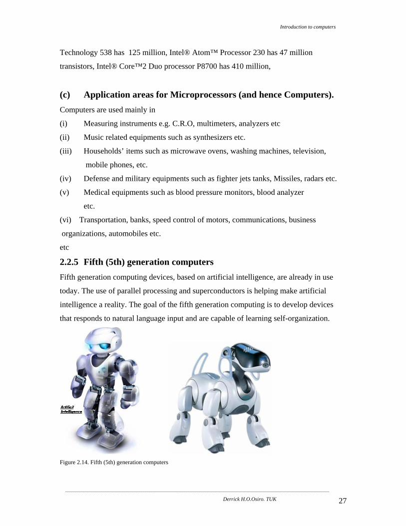
2.2.5 Fifth (5th) generation computers Fifth generation computing devices, based on artificial intelligence, are already in use
today. The use of parallel processing and superconductors is helping make artificial
intelligence a reality. The goal of the fifth generation computing is to develop devices
that responds to natural language input and are capable of learning self-organization.
Figure 2.14. Fifth (5th) generation computers

Introduction to computers
Derrick H.O.Osiro. TUK 28
Characteristics
1) The fifth generation computers use super large scale integrated chips.
2) They have artificial intelligence.
3) They are able to recognize image and graphs.
4) Fifth generation computer aims to solve highly complex problem including
decision making, logical reasoning.
5) Fifth generation computers are intended to work with natural language.
Unlike the distinct changes from first to 4th generations, there is a grey line
separating 5th and 6th generation computers.
2.3 TYPES OF COMPUTERS There are a variety of computers, with a variety of their operational characteristics.
The two basic types of computers, with respect to the computer's operational
characteristics are analogue and digital computers.
2.3.1 Analogue Computers: They work on continuous process e.g. temperatures, pressure and speed. They are called
continuous because they do not jump form one value to the next one. E.g. In a gas station
gasoline pumps contain an Analog computer that converts fuel flow measurement into
quantity and price values.
The examples of analogue devices include slide rule, car speedometer, and potentiometer.
These are the computers that perform arithmetic operations and logical comparisons by
measuring changes in physical magnitudes, e.g., electronic voltage, pressure changes,
temperature changes, etc. These physical variations are analogous to the represented
numerical values of the data being processed.
The application of analog computers is confined to specialized areas as in scientific or
engineering experiments, manufacturing processes and military weapons, e.g., the
temperature variations in a chemical process are converted into electronic voltage for
analog computer's mathematical analysis.

Introduction to computers
Derrick H.O.Osiro. TUK 29
2.3.2 Digital Computers These are most commonly used type of computers and they take discrete data. They
perform arithmetic operations and logical comparisons on digits (1's and 0's) and on other
characters that have been numerically coded.
They work on numbers i.e. discrete processes that are separate and countable. Every
number, character, special symbol has a numeric value in the computer memory.
These computers can process both numeric and alphabetic or alphanumeric data. The
accuracy of digital computers is influenced by the memory size and the precision of the
data input.
These types of computers are used in a wider cross section of the application areas such
as scientific, industrial and most of the other computer based data processing
applications.
2.3.3 Hybrid Computers: Hybrid computers are designed by interconnecting the digital computer and analog
computers' element directly into one processor, using a suitable interfacing circuitry.
That is both the digital and analog features are built within the same computer/processor.
Hybrid computers are more advantageous because they combine both the functional
capabilities of the digital and analog computers, though because of their capabilities they
are more expensive.
2.4 CLASSIFICATION OF DIGITAL COMPUTER 2.4.1 Depending on Functions Performed
(a). Special Purpose Computers: These digital computers are designed to carry out special processing tasks in one or more
applications. In a computer network where the host computer serves several other
computers or terminals/work stations connected to it, another specialised type computer
known as the Front End Processor (FEP) may be used to specialise in the work of
network control, i.e., controlling the data, instructions and the information
communication between the various work stations and the host computer.

Introduction to computers
Derrick H.O.Osiro. TUK 30
In modern offices, computers are used in typing and editing textual information. The
computer is used to replace the use of the normal conventional typing machines such as
the typewriter. In this computerised word processing, automatic typing and text editing is
done by the special purpose computers described as the word processors.
(b). General Purpose Computers: These are computers designed to be used in a variety of application environments as
required. This capability of the computers is made feasible by passing into the computer
the relevant sets of instructions, to be used by the computer to carry out the desired
processing tasks at any given time.
The range of application areas for these computers is influenced by the volume of the
data to be processed, the processing power of the computer, the information timing, i.e.,
when the information is required and the input/output facilities supported by the
computer.
General-purpose computers can also be described as scientific computers if they have got
the ability for high speed processing of numerical data of complex mathematical
procedures.
General-purpose computers can also be described as business computers if they have got
the ability of processing large volumes of data as in e.g., payroll, billing and other
business applications.
(c) Dedicated Computers: These are computers, which are capable of performing a variety of tasks in different
application environments. In other words, dedicated computers are general-purpose
computers that are committed to some processing tasks, though capable of a variety of
tasks. A general-purpose computer, for example, can be dedicated to carry out word
processing tasks.

Introduction to computers
Derrick H.O.Osiro. TUK 31
2.4.2 Depending on processing capabilities (size)
(a) Microcomputers This term microcomputer, originally used for an independent ‘free-standing’ computer,
has become largely out-dated and replaced by the term personal computer (PC).
These are the most recent type of computer to be developed. In 1981 IBM introduced the
PCs. They are the smallest types of computers. Conventional PCs have a full keyboard, a
monitor, and can function as stand-alone systems. PCs can be categorized as:
(i) Pocket PCs/ Tablets
These are light, compact and highly portable. They have batteries and can operate with or
without an external power source. The pocket PC, sometimes called a palmtop, can
literally fit into a pocket or a handbag.
(ii) Laptop PCs
These, at about 3 kilograms, are slightly heavier than the pocket PC. They are often
called a notebook PC because they are about the size of a thick notebook.
The power of the PC may not be related to its size. Some user conveniences must be
sacrificed to achieve portability. For instance, input devices, such as keyboards and point-
and-draw devices are given less space in portable PCs and may be more cumbersome to
use. Portable computers take up less space and therefore have a smaller capacity for
permanent storage of data and programs.
(iii) Desktop PCs /Tower PCs
Desktops and tower PCs are not portable because they rely on an outside power source
and are not designed for frequent movement. Typically the desktop PC’s monitor is
positioned on top of the system unit component. The processing component of the tower
PC is designed to sit upright. The tower may be placed in any convenient location like a
nearby shelf or on the desk.
One person at a time uses a PC. The user turns on the PC, select the software to be run,
enters the data, and request the information. The PC like other computers is very versatile
and has been used for everything from communicating business colleagues to controlling
household appliances.
Unlike the large computers, the processor is contained on one silicon chip, instead of a
combination of chips. This processor in a PC is called a microprocessor.

Introduction to computers
Derrick H.O.Osiro. TUK 32
(b) Mainframes Mainframe computers are large computers in terms of price, power and speed. Until the
late 1960s, all computers were mainframe computers and they were expensive. In the late
1960’s computer vendors introduced smaller computers that were more affordable for
smaller companies. These were called minicomputers.
Mainframe computers are designed specifically for the multi-user environment, in
contrast to PCs which frequently are used as stand-alone computers. The amount of work
that can be performed by the mainframe computer system is enormous primarily by the
speeds of the input/output and storage devices.
Mainframe computers have very large processors with several hundred Gigabytes of
RAM. This allows them to be used by many users at the same time.
This type of computer would usually be used with very large and fast peripheral devices
and with many hard disk units. Used for processing and storage of data in organizations.
(c) Minicomputers Originally used to describe computers, which were cheaper and less well equipped than
mainframes, this term is becoming obsolete.
(d) Supercomputers Supercomputers are used to process very large amounts of data very quickly. The speed
of the supercomputer may be 100 times that of a large mainframe computer.
These are representative supercomputer applications:
Enable the simulation of airflow around an airplane at different speeds and
altitudes.
Auto manufacturers use supercomputers to simulate auto accidents on video
screens.
Meteorologists employ supercomputers to study how oceans and the atmosphere
interact to produce weather phenomena.
Hollywood production use supercomputers to create the advanced graphics used
to create special effects for movies and TV commercials.
Others include genetic research centers, electrical power generation and control,
missiles manufacturing and control centers, space research centers, etc

Introduction to computers
Derrick H.O.Osiro. TUK 33
3.0 COMPUTER COMPONENTS AND THEIR FUNCTIONS A simple computer system comprises the basic components: processor (Control Unit and
the Arithmetic and Logic Unit), Main Memory, Input Unit, Output unit and Storage Devices
The diagram below shows how the above are connected together:-
Figure 3.1. Components of computer system.
3.1 MAIN PROCESSOR (OR CENTRAL PROCESSING UNIT,
CPU). This is the ‘brain’ of the computer. It consists of:
3.1.1 A group of registers
These are high speed storage locations that temporarily store data and instructions during
processing. They may store a program instruction while it is being decoded, store data
while it is being processed by the ALU, or store the results of a calculation.
Some of the Registers types

Introduction to computers
Derrick H.O.Osiro. TUK 34
(a) Memory Data Register
It is located on the processor and it holds data waiting to be processed and information
waiting to be processed.
(b) Memory Buffer Register
It is located on the memory chip and it holds data waiting to be processed and
information waiting to be processed.
(c) Program Counter/ Sequential Control Register
This stores the address of the location in which the next instruction to be fetched from
memory is stored.
(d) Memory Address Register
It specifies the address in memory of the Location to be referenced by the control Unit.
(e) Current Instructions Register/ Instruction Register
It stores the instruction which currently being processed
(f) Accumulator
It holds operands and results of the Arithmetic &Logic Unit operations
3.1.2 Control Unit
This is the device in charge of the operations of the computer and its peripherals. The
control unit provides timing and harmonization for communication process between the
CPU and the peripherals and any other circuits connected to the CPU. The control unit
deciphers/ decodes each instruction stored in it and then carries out the instruction. It
directs the movement of electronic signals between main memory and the ALU. It also
directs these electronic signals between the main memory and the input and output
devices. For every instruction, the control unit carries out four basic operations, known as
the machine cycle. In the machine cycle, the CPU,
1. Fetches an instruction 2. Decodes the instruction,
3. Executes the instruction and 4. Stores the results.
The control unit receives requests in form of instructions from the main memory; it
interprets/decodes the received instructions and responds with control influences that
make the operation of the computer elements concerned to proceed as per the
instruction's requirements.

Introduction to computers
Derrick H.O.Osiro. TUK 35
It deals with each instruction in turns in a two-stage operation called the Fetch Execute
Cycle
3.1.3 Arithmetic and Logic Unit (ALU) The arithmetic/logic unit performs the arithmetic, comparison, and logical operations.
Arithmetic operations include addition, subtraction, multiplication, and division.
Comparison operations involve comparing one data item to another to determine if the
first item is greater than, equal to, or less than the other item. Logical operations work
with conditions and logical operators such as AND, OR, and NOT.
The control unit issues out commands to the ALU, indicating where in main memory to
get data to be manipulated, where to place the results achieved and how to interrelate the
data.
Data about to be processed is taken from the Main Memory as directed by the control unit
Via Memory Data Register into the Accumulator. The ALU then performs the required
operations on data as directed by the control unit. And then the results are stored in the
Accumulator. They are later moved from the Accumulator and then stored in the Main
Memory under the direction of the control unit and this process is called storing data.
Figure 3.2. CPU Processor chips

Introduction to computers
Derrick H.O.Osiro. TUK 36
There are different types of CPU from different companies. These include but not limited
to:
Intel: 80386, 80486, Pentium, Pentium with MMX, Pentium II, Pentium III,
Celeron, Pentium IV, Pentium Dual Core, Centrino, coppermine, core-i3,core-i7 etc
Motorola: 68000, PowerPC
AMD: Athlon, Duron, Thunderbird
Cyrix
They operates at different speeds e.g. 166MHz, 233MHz, 450MHz, 733MHz, 850MHz,
1.0 GHz, 2.4 GHz , 3GHz etc .The faster a CPU is, the faster it executes programs to
accomplish tasks.
3.2 INPUT UNIT. This is used to enter/capture data and programs (instructions), via a suitable device, into
the computer systems. Before data can be used within a computer system, it is usually
necessary to convert them into a format that supports processing by computer. Input
devices convert data into a form that makes them machine-sensible. A modern computer
makes use of a wide variety of input devices since data flowing in to the organization or
handled by an individual may take a number of different forms. The choice of an input
device will often depend upon the type and the quantity of data to be entered. Entering
data on a small scale is normally carried out by human operators using a number of
familiar input devices, such as keyboard and mouse. However, large-scale data input may
require the use of more specialized input devices. In many cases, a direct capture deice
will be used to acquire and store data automatically. Generally, the data are captured at
source and stored with little or no human intervention. Data obtained from sensors on a
production line, for example, might be stored and then processed automatically.
There are a wide variety of types of input devices which include but not limited to ;
keyboards, mouse, toggle switches, microphones, digital cameras, scanners, magnetic
encoders etc
3.2.1 Keyboard Keyboard is the main form of input (allows numbers/alphabetical characters etc. to be
entered directly). It has standard letters, numbers, punctuation found on a standard
Introduction to computers
Derrick H.O.Osiro. TUK 37
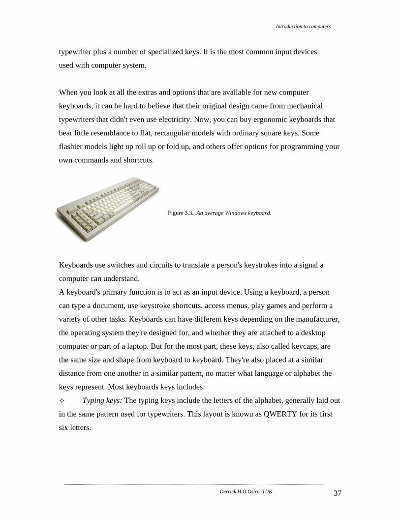
typewriter plus a number of specialized keys. It is the most common input devices
used with computer system.
When you look at all the extras and options that are available for new computer
keyboards, it can be hard to believe that their original design came from mechanical
typewriters that didn't even use electricity. Now, you can buy ergonomic keyboards that
bear little resemblance to flat, rectangular models with ordinary square keys. Some
flashier models light up roll up or fold up, and others offer options for programming your
own commands and shortcuts.
Figure 3.3. .An average Windows keyboard.
Keyboards use switches and circuits to translate a person's keystrokes into a signal a
computer can understand.
A keyboard's primary function is to act as an input device. Using a keyboard, a person
can type a document, use keystroke shortcuts, access menus, play games and perform a
variety of other tasks. Keyboards can have different keys depending on the manufacturer,
the operating system they're designed for, and whether they are attached to a desktop
computer or part of a laptop. But for the most part, these keys, also called keycaps, are
the same size and shape from keyboard to keyboard. They're also placed at a similar
distance from one another in a similar pattern, no matter what language or alphabet the
keys represent. Most keyboards keys includes:
Typing keys: The typing keys include the letters of the alphabet, generally laid out
in the same pattern used for typewriters. This layout is known as QWERTY for its first
six letters.

Introduction to computers
Derrick H.O.Osiro. TUK 38
Figure 3.4. Logitech wireless keyboard uses a QWERTY
layout.
Keyboards can also use a variety of other typing key arrangements. The most widely
known is Dvorak, named for its creator, August Dvorak. The Dvorak layout places all of
the vowels on the left side of the keyboard and the most common consonants on the right.
The most commonly used letters are all found along the home row. The home row is the
main row where you place your fingers when you begin typing. People who prefer the
Dvorak layout say it increases their typing speed and reduces fatigue. Other layouts
include ABCDE, XPeRT, QWERTZ and AZERTY. Each is named for the first keys in
the pattern. The QWERTZ and AZERTY arrangements are commonly used in Europe.
The numeric keypad is a more recent addition to the computer keyboard. As the
use of computers in business environments increased, so did the need for speedy data
entry. Since a large part of the data was numbers, a set of 17 keys, arranged in the same
configuration found on adding machines and calculators, was added to the keyboard.
Figure 3.5. The numerical keypad.
Control keys: In 1986, IBM further extended the basic keyboard with the
addition of function and control keys. Applications and operating systems can assign
specific commands to the function keys. Control keys provide cursor and screen control.

Introduction to computers
Derrick H.O.Osiro. TUK 39
Four arrow keys arranged in an inverted T formation between the typing keys and
numeric keypad move the cursor on the screen in small increments.
Figure 3.6a. Optimus keyboard OLED arrow keys Figure 3.6b. This Optimus keyboard has programmable hot
keys.
Other common control keys include: Home, End, Insert, Delete, Page Up, Page Down,
Control (Ctrl) , Alternate (Alt) and Escape (Esc)
The Windows keyboard adds some extra control keys: two Windows or Start keys, and
an Application key. Apple keyboards, on the other hand, have Command (also known as
"Apple") keys.
Figure 3.6c Optimus keyboard OLED
Windows key
3.2.2 Pointing Devices A "pointing device" can also refer to a special "stick" (sometimes telescopic, to reduce
the length when not in use), or a lamp with a narrow light beam that is pointed at a map,
blackboard, slide screen, movie screen, etc.; sometimes the light is in the form of an
arrow.
One of the most natural of human gestures, the act of pointing , is incorporated in several
kinds of input devices. Compuer pointing devices control the position of the cursor or
pointer on the screen. Pointing devices include the mouse and its variant, the touch
screen, trackballs, and various forms of pen input.

Introduction to computers
Derrick H.O.Osiro. TUK 40
(a) The mouse and its variants.
(i) Mouse The principal pointing toll used with microcomputers is the mouse.
It is a device that is rolled about on a desktop to direct a pointer on the computer’s
screen. It is used with computers that use Graphical User Interface (GUI). (( GUI allows
the user to control the operation of a computer program or item of computer hardware
using a pointing device such as a mouse by selecting options from icons and menu
options).The pointer is a symbol, usually an arrow that is used to select items from a list
(menu), on the screen or to position the cursor. The cursor, also called insertion point, is
the symbol on the screen that shows where data may be entered next, such as text in a
document. It is vital for intuitive drawing/graphics operations. A mouse eliminates the
need to type computer commands. Instructions are given by the user to the computer by
pointing an arrow or pointer on the screen to a picture or word and then clicking the
button on the mouse.
Figure 3.7a. Typical mouse Some mice have a scroll wheel between the buttons:
Some mice have no ball underneath, instead they have a light. They do not need to be
cleaned as often, does not wear out. Many of these work with special mouse pads and are
more accurate than ball mouse...good for sensitive drawings
Some mice are cordless.

Introduction to computers
Derrick H.O.Osiro. TUK 41
Figure 3.7b. Typical mouse
(ii) Trackball This is a movable ball, mounted on top of a stationary device, that can be rotated using
fingers or palm or the trackball is a ball inserted in a small external box near the
keyboard. The ball is rolled with the fingers to move the mouse cursor. Some people like
to think of the trackball as an upside-down. It is a kind like an upside-down mouse. The
ball is controlled usually by thumb and one finger and is used as a replacement for a
mouse
Figure 3.8. Typical trackball A trackball is not as accurate as a mouse, and it requires more frequent cleaning, but it is
a good alternative when desktop space is limited.
(iii) Pointing Stick/ Track points A pointing stick looks like a pencil eraser protruding from the keyboard between the G, H
and B keys. One move the pointing stick with the finger while using the thumb to press
buttons located in front of the space bar. A forerunner of the pointing stick is the
joystick, which consists of a vertical handle like a gearshift lever mounted on a base with
one or two buttons. Pointing sticks are used on laptop computers.
(iv) Track pad (Touch pad) This is a small, flat surface over which you slide your finger using the same movement
one would with a mouse. The cursor follows the movement of the finger. One “clicks” by
tapping the finger on the pad’s surface or by pressing buttons positioned close by the pad.

Introduction to computers
Derrick H.O.Osiro. TUK 42
Touch pads are also most often found on laptop computers. (The track pad has no moving
parts. One simply moves a finger about a small touch sensitive pad to move the mouse
cursor).
(v) Touch screen A touch screen is avideo display screen that has been sensitized to receive input from the
touch of a finger.
The screen is covered with a plastic layer, behind which are invisible beams of infrared
light. One can input a request for information by pressing on buttons or menus displayed
(Users make selection and control programs by pressing onto the screen). The answers to
the request are displayed as output in words or pictures on the screen. These screens are
normally used in kiosks, ATMs, airport tourist directories, hotel TV screens (for guest
checkout), department store, tablets, laptops, cell phones etc.
The function of a touch sensitive screen is similar to that of the light pen except that it is
activated by the operator touching the screen instead.
Figure 3.9. Touch sensitive screen
(b) Pen Input Some input devices used variations on an electronic pen . Examples are pen-based
systems,light pens and digitizers.
(i) Pen-based computer systems Pen-based computer systems allow users to enter handwriting and marks onto a computer
screen by means of a penlike stylus rather tan by typing on akeyboard. Pen computers
use handwriting recognision software that translates handwriitng characters made by the
pen, or stylus, into data that is usable by the computer. Many handheld computers and
PDAs have pen input, as do digitla notebooks.

Introduction to computers
Derrick H.O.Osiro. TUK 43
(ii) Light Pen Light pen is a light sensitive stylus, or pen-like device, connected by a wire to the
computer terminal. The light pen allows the operator to identify a particular point or
character displayed on the screen, and can be used alone or in conjunction with a
keyboard to add, rearrange or delete information displayed on the screen.
The user brings the pen to a desired point on the display screen and presses the pen
button, which identifies that screen location to the computer. Light pens are usually used
by graphic designers, engineers, illustrators or on PDAs.
Figure 3.10. Light pen
(iii) Digitizer A digitizer uses a mouse-like copying device called a puck, or an electronic pen, which
can convert drawings and photos to digital data. One form of digitizer is the digitizing
tablets also called a graphics tablet consists of a flat, rectangular, electronic plastic board
used to input drawings, sketches, or other graphical data. Each location on the graphics
tablet corresponds to a specific location on the screen. When you draw on the tablet with
either an electronic pen or a puck, the tablet detects and converts the movements into
digital signals that are sent into the computer. A puck is a device that looks similar to a
mouse, except that is has a window with cross hairs so the user can see through to the
tablet. Digitizing tablets are often used to make maps and engineering drawings.
(c) Source Data-Entry Devices Source data-entry devices create machine-readable data on a magnetic media or paper or
feed it directly into the computer’s processor.

Introduction to computers
Derrick H.O.Osiro. TUK 44
Source data-entry devices do not require keystrokes (or require only a few keystrokes) to
input data into the computer. Rather data is entered directly from source, without human
intervention. Examples include;
Scanning devices (e.g. imaging systems, bar-code readers, mark-a and character-
recognition devices, and fax machines),
Audio-input devices, web cameras and video input, and photographic input
(digital cameras),
Voice-recognition systems, sensors, radio-frequency identification devices, and
human-biology input devices.
(i) Scanning devices-imaging systems A scanner is a device, which use light-sensitive equipment to translate/converts text,
drawings, photos (graphics) and the like directly into machine language. It is similar to a
copy machine except that it creates a file of the document instead of a paper copy.
In text scanning each character is compared to known shape or pattern so that the
appropriate code for that character can be entered into a computer. If a character cannot
be recognized then a special unknown character is input for the user to edit with the
correct text.
Some scanners have spell checking facilities and in this case there is no need of typing
the text.
In graphic scanning the pattern of light and dark images on a page is converted into a
series of dots called picture elements or pixels and these can be stored as binary digits in
a computer memory.
Scanned images or texts can then be processed by a computer, displayed on a monitor,
stored on a storage device or transmitted to another computer.
Scanned photos can be used in brochures while the scanned documents can be faxed or
saved on a hard disk for records. There are many varieties of scanners depending on
resolution (i.e., picture quality) and mode of operation.

Introduction to computers
Derrick H.O.Osiro. TUK 45
Scanners types
Drum Scanner - A drum scanner is usually found in a professional printing business,
because they provide the highest level of image quality available. They
are used with a cylindrical drum that rotates past sensing elements to
complete scanning jobs. They are more on the expensive side and they
are much more advanced than typical desktop scanning. Figure 3.11. The flatbed scanner is the most popular type, and the flat
desktop design gives you a lot of scanning area. Items to be
scanned are placed on a glass plate, like a copier, so one can
scan multiple items of various shape and sizes, with the largest
paper size being either a letter or legal page, Figure.3.12.
depending on the model. Some models even include a transparency adapter to scan slides,
x-rays or other transparent originals. Flatbed scanners are highly recommended, if the
user is going to scan a good number of graphics or separate pieces of text. Flatbed
scanners are available with a SCSI, Parallel Port or USB Port Connector.
Sheet fed Scanner is fed a piece of paper into it, much like a fax machine. Sheet fed
scanners can only handle one piece of paper at a time, although some
models come with built-in automatic document feeder (ADF) to scan
multiple pages unattended. Figure.3.13.
Lightshow 3D Object Scanning System allows you to use flatbed scanner to scan 3D
objects, paper documents, photographs, transparencies, positives,
negatives, and x-rays. The LIGHTSHOW 3D Object Scanning System
uses the high resolution capabilities of existing flatbed scanner to create
sharp, crisp, accurate details of 3D objects. Figure.3.14. Film (Photo) scanners used for scanning of photo pictures, slides and
input images to computer. Figure.3.15.

Introduction to computers
Derrick H.O.Osiro. TUK 46
Portable/Handheld scanners: With portable sheet-fed color scanning
devices scanner, the USB port connection feature allows
one to have one-cable hook up to a notebook or desktop
PC.
Figure.3.16.
C-Pen 20 scans text, numbers and small images from printed or hand-printed sources.
Line by line the data is sent into the document management system.
Digital Cameras: Digital cameras are a versatile tool that can produce
superior quality images. Though slower and more difficult to use than
user types of scanners, digital cameras are adaptable to a wide array of
documents and objects. Most fragile materials can be safely captured,
though the need to provide external lighting means. Digital camera Figure.3.17.
technology continues to improve, helped along by the growing consumer market.
(ii) Scanning devices-bar code readers Bar encoding is a special type of point-of-sale data recording. Although several different
bar codes exist, the most easily recognizable is the Universal Product Code (UPC).
Bar-code readers are photoelectric (optical) scanners that translate the symbols in the bar
code into digital. The bar code reader has a scanning device that translates black and
white (or light and dark) bars of different widths into electrical impulses. Thus, there is
no need to manually use a data entry device such as a cash register to key the data into
machine-readable form.
These are used to read in product codes quickly and without error especially in
supermarkets, grocery stores etc. They are also used for security cards
Figure.3.18.

Introduction to computers
Derrick H.O.Osiro. TUK 47
Figure.3.19. Application
Stock control/accounting.
Library.
Supermarket point of sales.
Advantages
Cost effective.
High accuracy reading.
Allow easy change of information in CPU.
Disadvantages
Not easy to change information on bar code.
Easy tampering.
Not human readable.
(iii) Scanning devices – marks-recognition and character-recognition
devices: There are three types of scanning devices that senses marks or characters. They are
usually refereed to by their abbreviations OCR, OMR, and MICR.

Introduction to computers
Derrick H.O.Osiro. TUK 48
(I) Optical Character Recognition (OCR) Optical character recognition (OCR) is a technology that involves reading typewritten,
computer-printed, or handwritten characters from-ordinary documents and translating the
images into a form that the computer can understand. Most OCR devices include a small
optical scanner for reading characters and software for analyzing what is read.
Typical rules for making Handwritten Characters Readable by OCR
(1) Data typed, hand-written on source document.
Figure.3.20.
(2) Data in special font.
(3) Compare pattern sensed with those stored in the machines.
(4) Assume character that matches closely to the read character.

Introduction to computers
Derrick H.O.Osiro. TUK 49
OCR is used frequently with turn-around documents. With this gas bill, you tear off the
top portion and return it with your payment
Application:
Turnaround documents.
Sales orders.
Purchase orders, etc.
Speed:
50 - 3000 character per second.
200 - 1200 documents per minutes for specified source documents.
Advantage
The input is both man and machine-readable
It enables documents to be read directly without the state of human intervention in
keying in.
Disadvantages
Initial cost of the system is very high
A character can be mistaken for another and those that are not recognized are
rejected
Slow reading.
(II) Optical Mark Reader (OMR) This technique involves the use of standard preprinted documents on which horizontal
marks are made with a pencil in predetermined positions. The position of each mark is
determined by dividing the form into areas or boxes printed in distinct color. Each mark
has a meaning, which is independent on its position. Directing thin beams of light on to
the paper surface it will be reflected back unless it is absorbed by the black pencil mark.
Applications
Examinations answer sheets.
Order forms.
Surveys.
Advantages
Straightforward.
Misreading less likely.

Introduction to computers
Derrick H.O.Osiro. TUK 50
No special equipment.
Disadvantages
Limited uses as not all data can be coded into marks.
Unsuitable for alphabetical data.
Require clear printing to explain marks made.
(III) Magnetic Ink Character Reader (MICR) Magnetic Ink Character Recognition (MICR) is a technology that allows details from
bank cheques to be read into a computer quickly and accurately
This method is widely used in the banking industry and it uses characters, which are
printed with ink containing magnet sable material.
When the characters are being read they are first passed through a magnetic field and
then the reader recognizes each character by its unique magnetic field pattern.
E.g. in banks a cheque book is given to a customer with each cheque pre-encoded with a
cheque serial number, bank codes, and Customer Account Numbers.
Figure.3.21. Once the cheque is passed to the bank the amount is post encoded manually and the
Figure.3.22. cheque can then be read.

Introduction to computers
Derrick H.O.Osiro. TUK 51
The characters printed on the cheque include the bank number, the account
number, and the cheque number. The amount of the check in the lower-right corer is
added after one writes the check.
With all these information, cheques can then be processed/cleared at very high speed.
Advantages
Forging is not easy.
Accurate reading.
Disadvantages
Proper care of documents necessary.
Limited data.
Data located in pre-determined position.
(iv) Scanning devices – fax machines A fax machine or facsimile transmission machine – scans an image and sends it as
electronic signals over telephone lines to a receiving fax machine, which prints out the
image on paper. There are two types of fax machines- dedicated fax machine and fax
modems.
(I) Dedicated fax machines are specialized devices that do nothing except send and
receive fax documents. These are what we usually think of as fax machines. They are
found not only in offices and homes but also alongside regular phones in public places
such as airports.
(II) A fax modem is installed as a circuit board inside the computer’s subsystem
cabinet. It is a modem with fax capability that enables one to send signals directly from
the computer to someone else’s fax machine or computer fax modem. With this device,
one does not have to print out the material from the printer and then turn around and run
it through the scanner on a fax machine. The fax modem allows the user to send
information more quickly than if one had to feed it page by page into a machine.
The fax modem is another feature of mobile computing ; it’s especially powerful as
receiving deice. Fax modems are installed inside portable computers, including pocket

Introduction to computers
Derrick H.O.Osiro. TUK 52
PCs and PDAs. If one links up a cellular phone to a fax modem in the portable computer,
one can send and receive wireless fax messages no matter where one is in the world.
The use of fax machines has declined in the recent to the advancement in the mobile
phone technologies.
(d) Voice Data Entry (VDE) – Voice-recognition systems and Audio
input devices A voice recognition system, using a microphone (or telephone) as an input device,
converts a person’s speech into digital signal by comparing the electrical patterns
produced by the speaker’s voice with a set of prerecorded patterns stored in the computer.
The sounds are converted into digital form and are either stored in a media e.g. a
magnetic tape or it is entered into a computer directly for processing. When the system is
to be used, an operator using the system keys in a word which he wishes the system to
recognize by saying then the sound is converted to binary form. Microphones are used to
convert the initial human voice into electrical signals (voltages).
Voice-recognition systems have had to overcome many difficulties, such as different
voices, pronunciations, and accents.
Audio input devices- records analogue sound and translates it for digital storage and
processing.
An audio signal can be digitized in two ways- by an audio board or a MIDI board.
Analogue sound from a cassette player or a microphone goes through a special circuit
board called an audio board (or sound card). An audio board is an add-on circuit board in
a computer that converts analogue sound to digital sound and stores it for further
processing and /or plays it back, providing output directly to speakers or an external
amplifier.
A MIDI board- MIDI, pronounced “middie,” stands for Musical Instruments Digital
Interface- provides a standard for interchange of musical information between musical
instruments, synthesizers, and computers.
Application
Assisting handicapped.
Security.

Introduction to computers
Derrick H.O.Osiro. TUK 53
Artificial Intelligence.
Advantage
Can be operated by a person without Keyboard knowledge
It’s very fast
Disadvantage: Accents and dialects
(e) Digital Cameras A digital camera uses a light-sensitive processor chip to capture photographic images in
digital form on a small diskette inserted in the camera or on flash memory chips. A
digital camera allows one to take pictures and store the photographed images digitally
instead of on traditional film. With some digital cameras, one downloads, or transfers a
copy of, the stored pictures to the computer by connecting a cable between the digital
camera and the computer and using special software included with the camera. Operating
systems like Windows XP to the newer ones do facilitate downloading without using the
special camera software. With other digital cameras, the pictures are stored directly on
storage media such as a floppy disk, PC Card, or flash card
Figure.3.23.Digital cameras
(i) PC cameras: These come from different companies with different resolutions,
features, use different software and have different connections (parallel, USB etc...!!!)
Figure.3.24.
(ii) Web cam is a camera that attaches to a computer to record moving images that
can then be posted on a website in real-time.

Introduction to computers
Derrick H.O.Osiro. TUK 54
(iii) Video-input cards- as with sound, most film and video tapes are in analogue
form; the signal is a continuously variable wave. For computer use, the signal that comes
from a VCR or a camcorder must be converted to digital form through a specialized
digitizing card –a video-capture card-that is installed in the computer. Two types of video
cards are frame-grabber video and full-motion video. Frame-grabber video cards can
capture and digitize only a single frame at a time. Full-motion video cards can convert
analogue to digital signals at the rates of up to 30 frames per second, giving the effect of
continuously flowing motion picture.
(f) Joysticks and Gamepads A joystick is typically used for game playing but can also be used to enter user requests.
This device enables the user to interact with screen image by moving the stick in multi-
directions. It is commonly used to play computer games.
Figure.3.25 .Joy stick
(g) Sensors:
A sensor is an input device that collects specific data directly from the environment and
transmits it to a computer. Although you are unlikely to see such input devices connected
to a PC in an office, they exist all around us, often in nearly invisible form. Sensors can
be used to detect all kinds of things: speed, movement, weight, pressure, temperature
humidity, wind current, fog, gas, smoke, light, shapes, and images and so on.

Introduction to computers
Derrick H.O.Osiro. TUK 55
Sensors are used to detect the speed and volume of traffic and adjust traffic lights. They
are used on mountain highways in winter-time as weather-sensing devices to tell workers
when to roll out snowplows. In some areas, sensors have been planted along major
earthquake fault lines in and experiment to see whether scientists can predict major earth
movements. In aviation, sensors are used to detect ice buildup on airplane wings or to
alert pilots to sudden changes in wind direction.
(h) Radio-frequency identification devices: Also known as RF-ID tagging, radio-frequency identification technology is based on an
identifying tag bearing a microchip that contains specific code numbers. These code
numbers are read by the radio waves of a scanner linked to a database. Drivers with RF-
ID tags can breeze through the tollbooths without having to even roll down their
windows; the toll is automatically charged to their accounts. Radio-readable ID tags are
also used by the Postal Service to monitor the flow of mail, by stores for inventory
control and warehousing, and in the railroad industry to keep track of rail cars. They are
even injected into dogs and cats, so that veterinarians with the right scanning equipment
can identify them if they become separated from their owners.
(i) Human biology-input devices:
Characteristics and movements of the human body, when interpreted by sensors, optical
scanners, voice recognition, and other technologies, can become forms of input. Two
examples are biometric systems and line-of-sight systems.
(i) Biometrics is the science of measuring individual body characteristics. Biometric
security devices identify a person through a fingerprint, voice intonation, or other
biological characteristic. For example, retinal-identification devices use a ray of light to
identify the distinctive network of blood vessels at the back of the eyeball.
(ii) Line-of-sight systems enable one to use the eyes to point at the screen. This
technology allows some physically disabled users to direct a computer. One can operate
a computer by focusing on particular areas of a display screen. A camera mounted on the
computer analyzes the point of focus of the eye to determine where the person is looking.
One can operate to computer by looking at icons on the screen and “press a key” by
looking at one spot for a specified period of time.

Introduction to computers
Derrick H.O.Osiro. TUK 56
3.3 OUTPUT UNIT This unit is used to give out (display) information (result of processed data). Some
commonly used output devices are character/page printers, monitors (cathode ray tubes,
CRT and liquid crystal displays, LCD), speakers, graph plotters, etc.
The operation of input/output devices is done via an input/output controller (or
input/output port). An input/output port controls the operation of peripheral according to
commands received from the CPU. It provides the CPU with information about the status
of the devices and coordinates the flow of data between external bus and the device. Two
or more devices may share the same input/output controller.
The quality of a computer system can be best assessed by the quality of the output it
generates. The essence of designing and implementing a data processing system is to
generate desirable output.
Text consists of characters that are used to create words, sentences, and paragraphs. A
character is a letter, number, punctuation mark, or any other symbol that requires one
byte of computer storage space.
Graphics are digital representations of non-text information such as drawings, charts, and
photographs.
Audio includes music, speech, or any other sound. To store such sounds, a computer
converts the sounds from a continuous analog signal into a digital format. Most output
devices require that the computer convert the digital format back into analog signals.
Video consists of images that are played back at speeds that provide the appearance of
full motion. Video often is captured with a video input device such as a video camera.
3.3.1 Display Devices A display device is an output device that visually conveys text, graphics, and video
information. Information shown on a display device often is called soft copy, because the
information exists electronically and is displayed for a temporary period of time.
Display devices include CRT monitors, flat-panel displays, and high-definition
televisions.

Introduction to computers
Derrick H.O.Osiro. TUK 57
(a) CRT Monitors A CRT monitor, or monitor, is a display device that consists of a screen in a plastic or
metal case.
Monitors that display only one colour are considered as monochrome.
The core of a CRT monitor is a large glass tube called a cathode ray tube (CRT). The
screen, which is the front of the tube, is coated with tiny dots (pixels) of phosphor
material that glow producing an image on the screen when electrically charged by an
electron beam.
Figure.3.26a.
(b) Flat-Panel Displays A flat-panel display is a lightweight, thin screen that consumes less power than a CRT
monitor. Common types of flat-panel displays includes LED, LCD and gas plasma.
(i) LCD Displays
LCD displays commonly are used in laptop computers, handheld computers, digital
watches,’ and calculators because they are thinner and more lightweight.
It uses a liquid crystal display (LCD), which has special molecules (called liquid
crystals). When an electric current passes through them, they twist, causing some light
waves to create the desired images on the screen.
Figure.3.26b.

Introduction to computers
Derrick H.O.Osiro. TUK 58
(ii) Gas Plasma Monitors
Used for larger displays while hanged on a wall. Gas plasma monitors use gas plasma
technology, which substitutes a layer of gas for the liquid crystal material in an LCD
monitor. When voltage is applied, the gas glows and produces the pixels that form an
image.
(c) 3D Headsets These are used in virtual reality
Figure.3.27.
Characteristics of display devices
Screens are made up of pixels - picture elements (i.e. dots). Pixels are the smallest
electronic elements that compose digital pictures.
All display devices have these common features:
(i) Size: length of diagonal of monitor (sometimes viewable length, sometimes tube
length). Common values are 15", 18", 19", 21", 24", 27", etc
(ii) Dot pitch: size of a single dot on the screen (0.23mm, 0.24mm, 0.26mm, 0.28mm
are common ), smaller is more crisp/less blurry.
(iii) Refresh options: interlaced (every second row shown first) vs. non-interlaced
refresh rate 60Hz, 72Hz, 90Hz
(iv) Maximum resolution: number of columns and rows of pixels (common values are
640x480, 800x600, 1024x768, 1280x1024). Better resolutions are today possible.
(d) Video card: This required for every computer that uses graphics. Many new ones have 3D
acceleration features.

Introduction to computers
Derrick H.O.Osiro. TUK 59
Figure.3.28.
3.3.2 Computer Output On Microform (Com) This method of output provides photographed type of computer output onto the
microform. The microforms are photographically reduced documents on films (magnetic
media) peruse photo negative for more insight.
There are two forms of the microform, the
(a) Microfilm, which is a film reel of 16mm roll.
(b) Microfiche which is rectangular shaped measuring about 105 by 148mm sheet.
Both the microfilm and microfiche are small and store several pages of A4 sized
information, about 3000 and 98, A4 pages respectively.
The computer displays the results onto the screen whose contents are then photographed
onto the microform, an on-line operation. Alternatively, the computer outputs the results
into a storage medium, e.g., the magnetic tapes, whose contents are read by a
transcriber’s machine and displays them onto the screen connected to the machine. The
contents being displayed on the screen are then photographed onto the microform. The
transcribers machine is not under direct influence of the computer hence this gives an off-
line operation.
Advantages
Saves on stationery and space;
Faster than printing;
Non-bulky hence conveniently transportable;
The microform contents are not easily read using naked eyes, hence guaranteeing
the security of the reports;
Have got longer life span as compared to e.g., paper medium output;
Disadvantages
They are expensive.
Cause eyestrain if an attempt is made to read he microform contents;

Introduction to computers
Derrick H.O.Osiro. TUK 60
Additional equipments for viewing the contents of the microform and for
producing full sized copies are required.
Application
The COM is conveniently used where the application generates voluminous output and
use of update is not frequently necessary. The COM is used for example in:
Libraries for books, catalogues, references;
To retain, e.g., town plans, maps, statistics, etc, in government authorities;
In banks, insurance companies, etc, to store personnel or customer's records and so on.
3.3.3 Graph Plotters These are output devices that produce graphical output, e.g., diagrams, maps and such
like outputs. The commonly commercially available graph plotters are the Flat Bed
Plotter and the Drum Plotter. These names are derived from the surface onto which
stationery has to be placed.
(i) The Flat Bed Plotter has a flat surface, 'bed' onto which the stationery is placed
for the pen to be moving over it in all directions to produce graphical output.
(ii) The Drum Plotter has got the 'drum' onto which the stationery is placed for he
drawing to be possible. The drum rolls the stationery, forwards or backwards, as the pen
moves over it to produce graphical output.
Graph plotters are applied basically in Computer Aided Design (CAD) and architectural
designs. In both the cases, the computer is used to form the graphical design and output
it through the graph plotters. The graphs plotters operate at slow speeds hence are
normally connected in an off-line mode to avoid wasting the computer time.
3.3.4 Magnetic Media The computer output/information from the computer memory can also be directed into
the magnetic storage media, e.g., the tape or disk, instead of being printed or displayed.
Such output directed to any of the magnetic storage media are thus magnetically coded.
Directing the computer output into magnetic media is usually necessary where such
results/output of processing is to be stored for future retrieval and/or further processing.

Introduction to computers
Derrick H.O.Osiro. TUK 61
3.3.5 Voice Output The information from the computer memory, which is in electronic form, is transformed
to wave forms, through various specialised additional circuitry, for the recipients of such
information to hear.
Uses of this Method
Voice output is useful where reading is not necessary or is impossible
Fast output is required
As learning aids
Emergency situations
Answering services
Post office talking clock
Disadvantages
It is non-permanent
It may be boring for prolonged output.
3.3.6 Printers A printer is an output device that produces text and graphics on a physical medium such
as paper or transparency film. Printed information is called hard copy (printout) because
the information exists physically and is a more permanent form of output.
Generally, printers can be grouped into two categories: impact and non-impact.
(a) Impact Printers An impact printer forms characters and graphics on a piece of paper by striking a
mechanism against an ink ribbon that physically contacts the paper. Because of the
striking activity, impact printers generally are noisy.
Two commonly used types of impact printers are dot-matrix printers and line printers.
Each of these printers is discussed in the following sections.
(i) Dot-Matrix Printers A dot-matrix printer is an impact printer that produces printed images when tiny wire
pins on a print head mechanism strike an inked ribbon . When the ribbon presses against
the paper, it creates dots that form characters and graphics.

Introduction to computers
Derrick H.O.Osiro. TUK 62
Figure.3.29
A dot-matrix printer produces printed images when tiny pins strike an inked ribbon.
(ii) Line Printer A line printer is a high-speed impact printer that prints an entire line at a time. It prints
fully formed characters when hammers strike a horizontal, rotating band that contains
shapes of numbers, letters of the alphabet, and other characters.
Figure.3.30.

Introduction to computers
Derrick H.O.Osiro. TUK 63
(b) Non-impact Printers A no impact printer forms characters and graphics on a piece of paper without actually
striking the paper. Some spray ink, while others use heat and pressure to create images.
Three commonly used types of no impact printers are ink-jet printers, laser printers, and
thermal printers.
(i) Inkjet printers An ink-jet printer is a type of no impact printer that forms characters and graphics by
spraying tiny drops of liquid ink onto a piece of paper. One factor that determines the
quality of an ink-jet printer is its resolution, or sharpness and clarity. Printer resolution is
measured by the number of dots per inch (dpi) a printer can output. The higher the dpi,
the better the print quality. With an ink-jet printer, a dot is a drop of ink. A higher dpi
means the drops of ink are smaller, which provides a higher quality image Most ink-jet
printers have a dpi that ranges from 300 to 1,440 dpi. Typically, printers with a higher dpi
are more expensive.
(ii) Laser Printers A laser printer is a high-speed, high-quality no impact printer. When printing a document,
laser printers process and store the entire page before they actually print it. A laser printer
creates images using a laser beam and powdered ink, called toner. The laser beam
produces an image on a special drum inside the printer. The light of the laser alters the
electrical charge on the drum wherever it hits.
When this occurs, the toner sticks to the drum and then is transferred to the paper through
a combination of pressure and heat.
Figure.3.31.

Introduction to computers
Derrick H.O.Osiro. TUK 64
(iii) Thermal Printers A thermal printer generates images by pushing electrically heated pins against heat-
sensitive paper. Standard thermal printers are inexpensive, but the print quality is low and
the images tend to fade over time. Thermal printers are, however, ideal for use in small
devices such as adding machines.
(iv) Special-Purpose Printers Other printers have been developed for special purposes.
I. A photo printer is a color printer designed to produce photo lab quality pictures
directly from a digital camera. A label printer is a small printer that prints on an adhesive-
type material that can be placed on a variety of items such as envelopes, disks,
audiocassettes, photographs, and toys. Many label printers are used to print bar codes.
II. Plotters and Large-Format Printers. Plotters and large-format printers are
sophisticated printers used to produce high-quality drawings such as blueprints, maps,
circuit diagrams, and signboards.. These printers are used in specialized fields such as
engineering, drafting, and graphic arts.
Figure.3.32.
3.3.7 Audio Output Audio is music, speech, or any other sound. Audio output devices are the components of
a computer that produce music, speech, or other sounds, such as beeps. Two commonly
used audio output devices are speakers and headsets.
(a) Speakers: These are used to produce sound outputs. They come in many varieties
(differing quality, wattage etc...). Sometimes built-in to the monitor or computer case

Introduction to computers
Derrick H.O.Osiro. TUK 65
Figure.3.33a. Sound Card: For a computer to process sound, it requires a sound card
Figure.3.33b..
3.3.8 Data Projectors A data projector takes the image that displays on a computer screen and projects it onto a
screen so that an audience of people can see the image clearly.
3.3.9 Output Devices for Physically Challenged Users The growing presence of computers in everyone’s lives has generated an awareness of
the need to address computing requirements for those with physical limitations. For users
with mobility, hearing, or vision disabilities, many different types of output devices are
available. Hearing-impaired users, for example, can instruct programs to display words
instead of sounds. With Windows, such users also can set options in the Accessibility
Properties dialog box to instruct Windows to display visual signals in situations where
normally it would make a sound
Visually impaired users can change Windows settings such as increasing the size or
changing the color of the text to make the words easier to read. Instead of using a
monitor, blind users can utilize speech output, where the computer reads the information
that displays on the screen. Another alternative is a Braille printer, which outputs
information in Braille onto paper.

Introduction to computers
Derrick H.O.Osiro. TUK 66
3.4 MEMORY [STORAGE DEVICES] A storage device accepts data, stores them and releases them on demand at a later time.
There are two main types of storage devices used in modern computers, namely primary
memory (main memory) and secondary memory (backing storage).
There are mainly two types of memories:-
3.4.1 Main Memory (Main Storage) These are made up of semiconductor memories, which are relatively fast but expensive.
Examples are Random Access Memory (RAM) and Read Only Memory (ROM).
(a) RAMs RAMs are used in computers for the temporary storage of programs and data. Data can be
written to and read from RAM easily. They store information or data so long as the
power is on; hence it is volatile.
Since it is easy to change the contents of a RAM, RAMs are the working memory of a
computer system (where data is manipulated).Types of RAMs include; Static RAM
(SRAM) and Dynamic RAM (DRAM).
(b) ROMs The information stored in a ROM can only be read but cannot be altered during normal
operations. The information is not lost when power goes off and hence ROMs are non-
volatile. ROMs are designed to hold data that are either permanent or will not change
frequently. Programs stored in ROM are called firmware. Type of ROMs includes
MROM, PROM, EPROM, and EEPROM.
Figure.3.34.A RAM The more the memory, the more the programs a user can run at once. They often translate
to faster computer. They come in different capacities (512MB, 2GB, 4GB, 8GB, 16GB,
and even 32 GB) and different types/speeds or models (EDO, SDRAM, cache)

Introduction to computers
Derrick H.O.Osiro. TUK 67
(c) Flash memory
Another type of non-volatile memory is called flash memory or flash ROM. Flash
memory can be erased electronically and reprogrammed. Flash memory is used to store
programs on personal computers, as well as cellular telephones, printers, digital cameras,
pagers, and personal digital assistant.
(d) CMOS Complementary metal-oxide semiconductor (CMOS) memory is nonvolatile memory
used to store configuration information about the computer, such as the type of disk
drives, keyboard, and monitor; the current date and time; and other startup information
needed when the computer is turned off. CMOS use battery power to retain information
even when the power to the computer is turn off
(e) Cache Memory: This is a high-speed memory. The speed of cache memory compares to that of the CPU.
The cache memory for its speed therefore is used to interface the slow communicating
main memory to the CPU. The cache memory therefore acts as a buffer that receives the
data, instructions and/or information from the main memory, at the speed of the main
memory and remits them to the CPU at the speed of the CPU and vice versa. Note that
this consideration isolates the memory from the CPU.
The cache memory is usually used in large computer systems, which ever the case it
speeds up the rate of processing by easing communication between the CPU and the main
memory, that is the movement of data and instructions to the CPU and remitting back to
the main memory of the intermediate results. The cache memory design is based on the
semi conductor elements.
3.4.2 Secondary (auxiliary or Backup or mass storage) These are used to supplement the main memory and are external to the main computer.
They have the capacity to store millions of information, without the need of electrical
power. They provides storage for programs and data not currently being executed
(operated on), but which will be transferred to the main storage (RAM) when required.

Introduction to computers
Derrick H.O.Osiro. TUK 68
In comparison to the main memory, the mass memory storage device;
are cheap
has high storage capacity
are non-volatile (store information more permanently)
are very slow
Commercially available storage devices are mostly magnetic based, e.g. magnetic tapes,
magnetic disks, and cassettes. Other devices use optical techniques e.g. CDROMs etc.
(a) Magnetic Disk Storage
Magnetic disk drives are comprised of one or more circular rotating disks coated with
magnetic material that is used for the recording of data.
Data are recorded into concentric rings known as tracks. A track is sub-divided into
sectors.
Figure.3.35
The two common types of magnetic disks are floppy disks and hard disks.
(i) Floppy disks The most common floppy disk now in use is the 3.5" disk. The assembly comprises a
flexible disk protected by a plastic jacket or cover. The jacket/cover has an aperture,
which allows the read/write head to retrieve or store data. 3.5" Floppy diskette is a
removable, round flat piece of mylar plastic that stores data and programs as magnetized
spots.
Figure.3.36

Introduction to computers
Derrick H.O.Osiro. TUK 69
They can be used to transfer data from machine to machine. It requires a floppy disk
drive. Typical diskettes hold 1.44 MB and have write-protection capability (like VHS
tapes and audio cassette tapes).
5.25 inch disk
Manufacturer’s label
Write Protect Notch
Spindle Hole
Sector / Index HoleJacketRead / Write Notch
Label
Write / ProtectTab
RecordingWindow withSliding Cover
3.5 inch disk
Figure.3.37a,b
Floppy disks has become obsolete
(ii) Hard Disks
It comprises at least one rigid disk protected by a strong, and usually air-tight, casing.
The hard disk is usually a self contained unit containing many disks, read/write head,
access arms and a motor enclosed within the casing, and the electronic circuit board
controlling the disk operations attached to the external of the casing. Hard disc drives are
made of thin but rigid metal or glass platters covered with a substance that allows data to
be held in the form of magnetic spots. They are tightly sealed within an enclosed unit to
prevent foreign matter e.g. dust, smoke and is usually the main auxiliary storage unit of a
personal computer (often called the "C" drive)

Introduction to computers
Derrick H.O.Osiro. TUK 70
Figure.3.38. Hard disks
It is faster than floppy and can hold thousands of Giga Bytes of data. Just like floppy
disks, data is stored in tracks/ sectors of a rotating disk.
(iii) Zip/jazz drives (Hard disk cartridges or removable hard disks) These consist of one or more platters enclosed along with read/write heads in a hard
plastic case. A cartridge which is not much larger than a floppy disk may hold/stores as
much as 2GB of data. They are faster than diskettes.
Figure.3.39s
Tape drives: Magnetic tape is thin plastic tape that has been magnetically coated for
storing data as magnetic spots. Tapes are used in magnetic tape units (reels) and in

Introduction to computers
Derrick H.O.Osiro. TUK 71
cartridges. These are slower than disks). They are good for backups (cheap). Capacities
can reach up to 6TB
Figure.3.40.
(b) Compact (Optical) Disk Storage In this form of storage, a light source, usually laser is used to fetch data patterns onto the surface
of the disk. Normally, two laser light sources are used; a weak laser is used to read data while a
stronger laser is used to record data by burning pits under the surface of the disk.
Figure.3.41. Two basic types of compact discs designed for use with computers are a CD-ROM and
DVD-ROM.
(i) CD/ROM
CD-ROM stands for Compact Disk Read Only Memory. It is a non-erasable backing. A
CD-ROM can hold up to 700 MB of data, instructions, and information, or about 450
times that which can be stored on a high-density 3.5-inch floppy diskThese come in
different speeds (4X (600 KB/s, 8X (1.2 MB/s), 24X (3.6MB/s), 40X (6 MB/s), 52x ...).
Some are read only, some write once, some re-writable. High-power laser beam is used to

Introduction to computers
Derrick H.O.Osiro. TUK 72
represent data by burning tiny pits into the surface of a hard-plastic disk. To read data, a
low-powered laser light scans the disk surface: Pitted areas are interpreted as a 1 bit. The
optical disk technology used with computers consists of mainly: CDROM disks (texts,
graphics and sound), CD-R disks, CD-RW disks. Most new software comes on CD's and
so new computers often come with CDROM drive.
Figure.3.42.
(ii) DVD (Digital Video Disks or Digital Versatile Disks): A DVD-ROM (digital video disc-ROM) is an extremely high capacity compact disc
capable of storing from 4.7 GB to 17 GB. DVD-ROM looks just like a CD-ROM but
stores data, instructions, and information in a slightly different manner by making the
disc denser by packing the pits closer together or using two layers of pits.
Figure.3.43.
(C) OTHER TYPES OF MEMORY
Various types of memory are explained as under:
(i) Holographic Memory This type of memory uses the principle of light to store data, instructions and
information. Hence it is also described as optical memory. The data, instructions and or
information stored are in terms of smear of dots on light sensitive plate. These memories
are non-volatile and have got vast storage capacity.
(ii) Buffers This is a special purpose temporary memory location, used during input/output (I/O) or
processing to hold data and/or instructions temporarily between communicating elements.
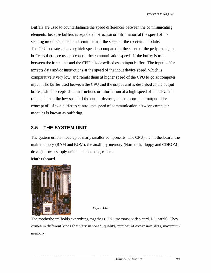
Introduction to computers
Derrick H.O.Osiro. TUK 73
Buffers are used to counterbalance the speed differences between the communicating
elements, because buffers accept data instruction or information at the speed of the
sending module/element and remit them at the speed of the receiving module.
The CPU operates at a very high speed as compared to the speed of the peripherals; the
buffer is therefore used to control the communication speed. If the buffer is used
between the input unit and the CPU it is described as an input buffer. The input buffer
accepts data and/or instructions at the speed of the input device speed, which is
comparatively very low, and remits them at higher speed of the CPU to go as computer
input. The buffer used between the CPU and the output unit is described as the output
buffer, which accepts data, instructions or information at a high speed of the CPU and
remits them at the low speed of the output devices, to go as computer output. The
concept of using a buffer to control the speed of communication between computer
modules is known as buffering.
3.5 THE SYSTEM UNIT The system unit is made up of many smaller components; The CPU, the motherboard, the
main memory (RAM and ROM), the auxiliary memory (Hard disk, floppy and CDROM
drives), power supply unit and connecting cables.
Motherboard
Figure.3.44.
The motherboard holds everything together (CPU, memory, video card, I/O cards). They
comes in different kinds that vary in speed, quality, number of expansion slots, maximum
memory

Introduction to computers
Derrick H.O.Osiro. TUK 74
3.6 Case The system unit is fitted into a case with all disk drives and a power supply. There are
different types - desktop, tower, mini tower etc...
Figure.3.45.
Here is a typical Personal Computer (PCs)
Figure.3.46.

Introduction to computers
Derrick H.O.Osiro. TUK 75
Here are some Mac computers (Mac G3 Cube, I-Mac, IBM Aptiva, macPro ...):
Figure.3.47.
REFERENCES 1. Brian K. Williams and Stacey C. Sawyer (2000), Using Information Technology,
(Complete version- seventh edition), Irwin McGraw-Hill, New York
2. Assorted websites
3. Mr Owira, Lecture notes (School of ICT, TUK)
4 Paul Bocij, Dave Chaffey, Andrew Graesley and Simon Hickie, (2003), Business
Information Systems (second edition) Prentice Hall, London