Introduction Prerequisites: Step1: Downloading and...
19
Introduction This document has details of implementation of rgb_led demo on MPLAB X IDE using the MCC plugin. The rgb_led demo displays a colour on the RGB LED. The colour changes from RED->GREEN, GREEN->BLUE, BLUE- >RED for every press of the switch button ‘S1’ on the board. The documentation follows a step-by-step approach to create and run the demo. The demo is created for pic32mx470 curiosity development board. Prerequisites: You will need the following Microchip development tools to run RGB LED Demo 1. PIC32MX470 Curiosity Development Board (DM320103), available from Microchip Direct 2. Download and install latest version of MPLAB® X Integrated Development Environment (IDE) 3. Download and install the latest version of MPLAB® XC32 Compiler Procedure Steps Step1: Downloading and Adding the MCC Plugin 1. Browse to http://www.microchip.com/mplab/mplab-code-configurator\ 2. Download the MCC tool from the web-site. Directions shown in the below graphic. Downloaded file will be a file with .nbm extension. 3. Open MPLAB X IDE. Go to Tools > Plugins
Transcript of Introduction Prerequisites: Step1: Downloading and...

Introduction This document has details of implementation of rgb_led demo on MPLAB X IDE using the MCC plugin. The rgb_led demo displays a colour on the RGB LED. The colour changes from RED->GREEN, GREEN->BLUE, BLUE->RED for every press of the switch button ‘S1’ on the board. The documentation follows a step-by-step approach to create and run the demo. The demo is created for pic32mx470 curiosity development board.
Prerequisites: You will need the following Microchip development tools to run RGB LED Demo
1. PIC32MX470 Curiosity Development Board (DM320103), available from Microchip Direct 2. Download and install latest version of MPLAB® X Integrated Development Environment (IDE) 3. Download and install the latest version of MPLAB® XC32 Compiler
Procedure Steps
Step1: Downloading and Adding the MCC Plugin 1. Browse to http://www.microchip.com/mplab/mplab-code-configurator\
2. Download the MCC tool from the web-site. Directions shown in the below graphic. Downloaded file will be a
file with .nbm extension.
3. Open MPLAB X IDE. Go to Tools > Plugins
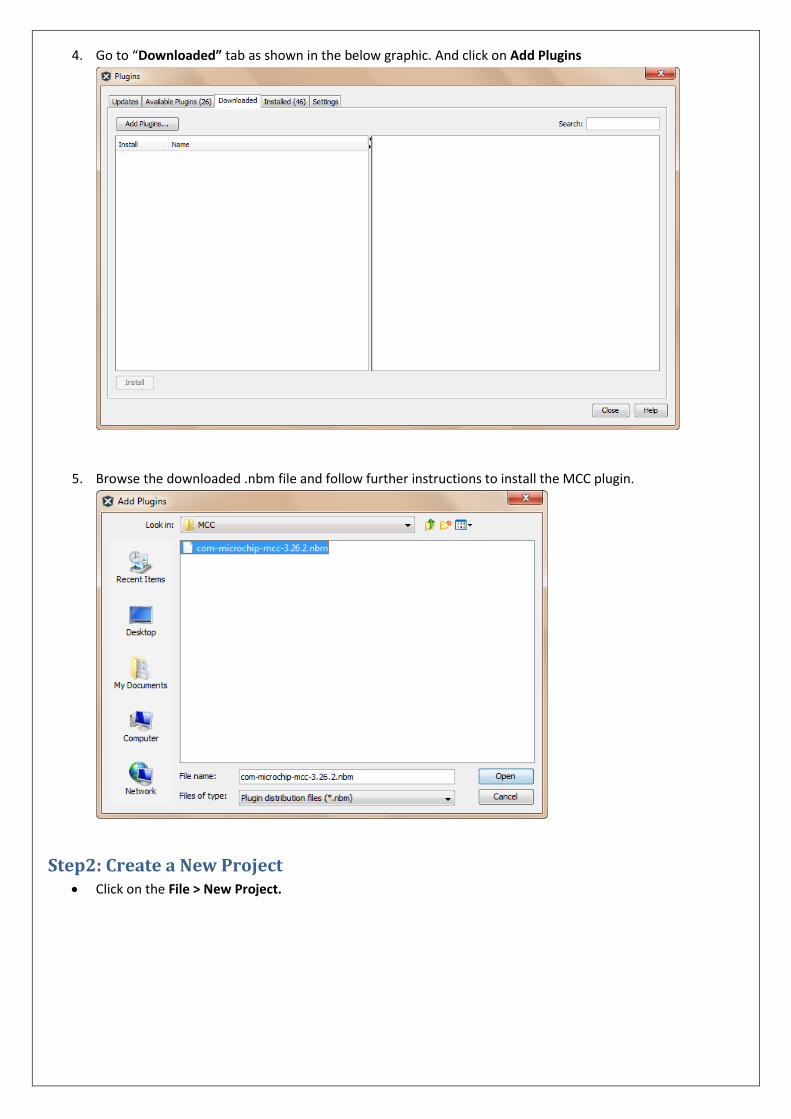
4. Go to “Downloaded” tab as shown in the below graphic. And click on Add Plugins
5. Browse the downloaded .nbm file and follow further instructions to install the MCC plugin.
Step2: Create a New Project Click on the File > New Project.

Choose Project

Select Device
Select Tool
Select Plugin Board ( No Plugin boards are selected)

Select Compiler Used
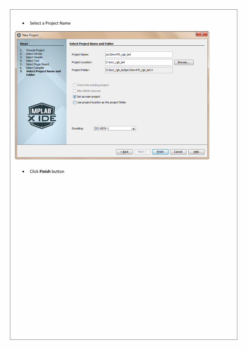
Select a Project Name
Click Finish button
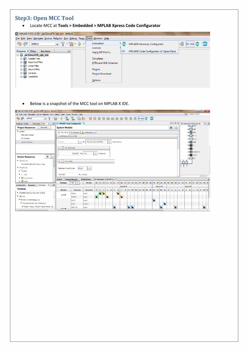
Step3: Open MCC Tool Locate MCC at Tools > Embedded > MPLAB Xpress Code Configurator
Below is a snapshot of the MCC tool on MPLAB X IDE.

Step4: Project Specific Configurations
Configuring the System Module
Configure the Internal Oscillator as shown in the below graphic
Disable the Watchdog as shown in the below graphic
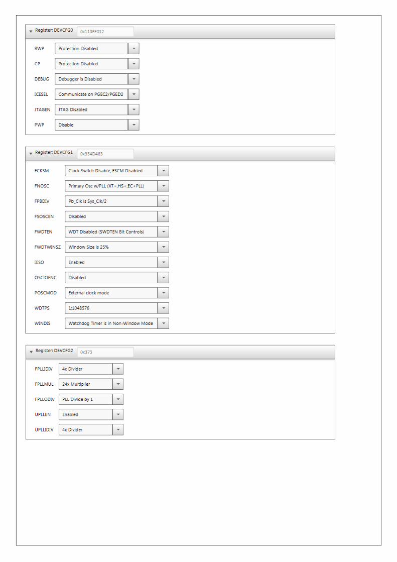
Configuring the Device Configuration Registers


Adding required peripherals and configuring them.
Go to Device Resources window in MCC tool. Double click on
OC3
OC4
OC5
Timer2
By doing this these peripherals will be added as “Project Resources”. We will do the configuration of these
peripherals now.
Configuring the OCx peripheral: As the OC3, OC4 and OC5 are configured identically, only OC3 configuration is described below. DO the similar configurations for the otrher OC peripherals as well.

Configuring the Timer2 peripheral:

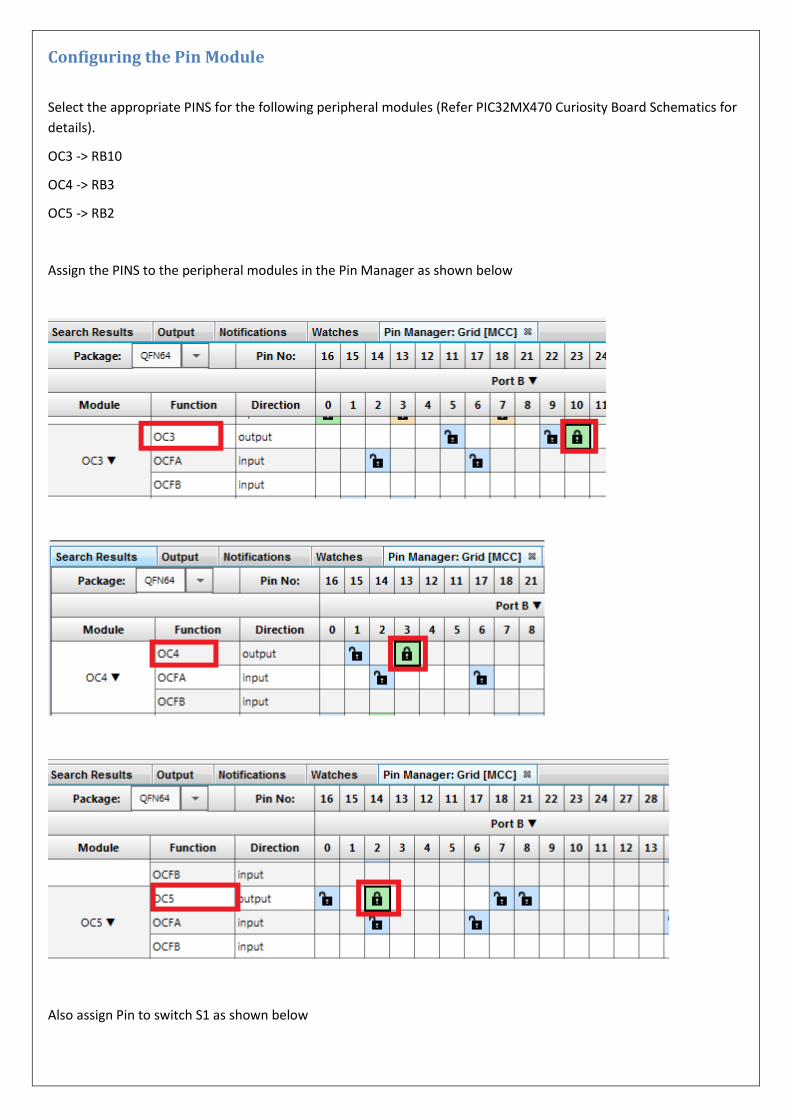
Configuring the Pin Module
Select the appropriate PINS for the following peripheral modules (Refer PIC32MX470 Curiosity Board Schematics for
details).
OC3 -> RB10
OC4 -> RB3
OC5 -> RB2
Assign the PINS to the peripheral modules in the Pin Manager as shown below
Also assign Pin to switch S1 as shown below

Enable Pull up and Change notice for the S1 switch pin (RD6). The Pin settings in the Pin Module should look as
follows.

Configuring the Interrupt Module from Project Resources
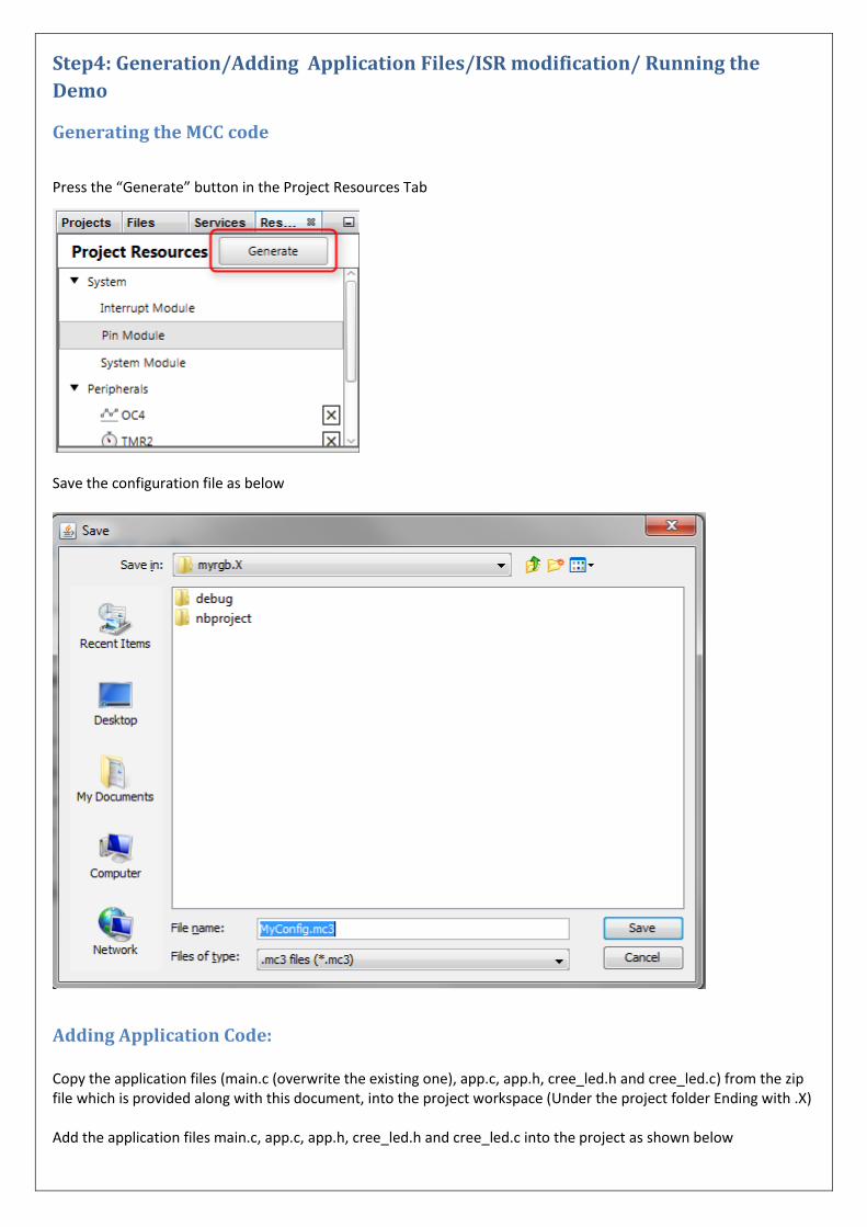
Step4: Generation/Adding Application Files/ISR modification/ Running the
Demo
Generating the MCC code
Press the “Generate” button in the Project Resources Tab
Save the configuration file as below
Adding Application Code: Copy the application files (main.c (overwrite the existing one), app.c, app.h, cree_led.h and cree_led.c) from the zip file which is provided along with this document, into the project workspace (Under the project folder Ending with .X) Add the application files main.c, app.c, app.h, cree_led.h and cree_led.c into the project as shown below

Modify the SYSTEM_Initialize in mcc.c as shown below.
Adding Interrupt Code: Modify the ISR in pin_manager.c under MCC Generated Files, as shown below.
#include "../app.h" extern APP_DATA appData; /* Interrupt service routine for the change notification interrupt. */ void __ISR (_CHANGE_NOTICE_VECTOR, IPL1AUTO) _CHANGE_NOTICE ( void ) { if(IFS1bits.CNDIF == 1) { // Clear the flag IFS1bits.CNDIF = 0; } appData.state = APP_STATE_SERVICE_TASKS; }

Running the Demo:
Compile and Run the demo. At every button press the colour of the RGB LED changes.