
Introduction - Asia-Pacific Telecommunity · Web viewIn recent years mobile broadband (MBB) system...
83
APT REPORT ON FIXED WIRELESS SYSTEM IN APT REGION No. APT/AWG/REP-65 Edition: September 2016 Adopted by
Transcript of Introduction - Asia-Pacific Telecommunity · Web viewIn recent years mobile broadband (MBB) system...

APT REPORT ONFIXED WIRELESS SYSTEM IN APT REGION
No. APT/AWG/REP-65Edition: September 2016
Adopted by
20th Meeting of APT Wireless Group6 – 9 September 2016
Bangkok, Thailand
(Source: AWG-20/OUT-07)

APT/AWG/REP-65
APT REPORT ON FIXED WIRELESS SYSTEM IN APT REGION
Table of Contents
1. Introduction.......................................................................................................3
2. Scope.................................................................................................................3
3. Vocabulary of terms.........................................................................................3
4. References.........................................................................................................4
5. Related ITU-R studies......................................................................................8
6. APT members current usage and future plan on Fixed Wireless System.........8
6.1. Current status of assignment/usage of frequency for Fixed Wireless Systems(FWS) 8
6.1.1.Frequency bands allocated to the fixed service in the ITU Radio Regulations8
6.1.2.Current status of frequency assignment and bandwidths in the Asia-Pacific region. .9
6.1.3.Utilization of FWS and network characteristics of each country.....................16
6.2. Trends concerning standardization and regulation for FWS............................21
6.2.1.Methods for frequency assignment and licensing of FWS in each country.....21
6.2.2.Standardization activities concerning FWS in each country............................26
6.3. FWS Technology trends...................................................................................28
6.3.1.Technology development in each country........................................................28
6.3.2.Recent trends in each country...........................................................................30
6.4. Analysis of present demands and future usage for FWS..................................32
6.4.1.Demands for FWS based on current utilization................................................32
6.4.2.Future usage plan for FWS and consideration for possible new usages...........33
7. Progress of technology and industry to support Fixed Wireless System future trends
7.1. Transceiver Technologies...................................................................................38
7.2. Antennas..............................................................................................................40
7.2.1. Passive antenna................................................................................................40
7.2.2. Active antenna..................................................................................................42
7.3. Network architecture (Technologies)..................................................................43
7.4. Technologies for achieving high data rates.........................................................43
7.4.1. Impulse Radio..................................................................................................43
7.4.2. FWS using high frequency bands....................................................................45
7.4.3. Intra-frequency full duplex system..................................................................50
Page 2 of 63

APT/AWG/REP-65
7.5. Device technologies............................................................................................51
7.5.1. Superconducting bandpass filter......................................................................51
7.5.2. EER Power amplifiers and the nonlinear distortion compensation technique 53
7.6. Propagation considerations.................................................................................57
8. Conclusion........................................................................................................59
ANNEX 1. Application examples..............................................................................60
Page 3 of 63

APT/AWG/REP-65
1. IntroductionIn recent years mobile broadband (MBB) system has experienced extraordinary improvement which results in increasingly high requirement for backbone and backhaul radio frequency spectrum to support MBB network operation.
In addition to the increase in demand for backbone and backhaul wireless communication systems for mobile backhaul due to the rapid traffic increase in mobile networks, fixed wireless systems are expected to be widely used in diverse applications including FWA (Fixed Wireless Access), disaster mitigation purposes, infrastructure-related networks, and high-resolution image transmission.
Reflecting such an increase in demand for fixed wireless systems, active discussion for developing technical standards on fixed wireless systems is being carried out at ITU-R SG5 WP5C1 and other international standardization organizations, such as ECC (Electronics Communications Committee).
In the Asia-Pacific region, however, while some countries are starting research and development in anticipation of future market development, specific activities for technology standardization have not yet taken place.
Considering the circumstances above, to progress research on frequency use, relevant technologies and future needs for fixed wireless communication in the Asia-Pacific region is critical in order to promote the incorporation of fixed wireless systems in a wide range of application fields, to expand the market, and at the same time, to realize effective use of a wide range of frequency bands in micro and millimeter waves.
2. Scope
This report covers information regarding current usage, demand and market forecast, standardization, guidelines, future plans and research and development status for fixed wireless systems from APT countries.
3. Vocabulary of termsACM Adaptive Code and Modulation
APT Asia Pacific Telecommunity
ASK Amplitude Shift KeyingATDE Adaptive Time Domain EqualizerATPC Automatic Transmit Power ControlBER Bit Error RatioBPF Band Pass FilterCNR Carrier to Noise Power RatioCS Channel SeparationDFE Decision Feedback Equalizer
1 Report ITU-R F.2323, “Fixed Service Use and Future Trends”
Page 4 of 63

APT/AWG/REP-65
ECC Electronic Communications CommitteeEER Envelope Elimination and RestorationEVM Error Vector MagnitudeFDD Frequency Division DuplexFEC Forward Error CorrectionFIR Finite Impulse ResponseFWA Fixed Wireless AccessFWS Fixed Wireless System(s)ICT Information and Communication Technology
IMT International Mobile Telecommunications
IP Internet ProtocolIR Impulse RadioLE Linear EqualizerLDPC Low Density Parity Check (code)LO Local OscillatorLTE Long Term Evolution
MBB Mobile Broadband
OOK On-Off KeyingPA Power AmplifierPSK Phase Shift KeyingRF Radio FrequencyQAM Quadrature Amplitude ModulationQoS Quality of ServiceQPSK Quad Phase Shift KeyingSHF Super High FrequencySTM Synchronous Transport ModuleTCM Trellis Coded ModulationTDD Time Division DuplexXPIC Cross Polarization Interference Canceller
4. References
ITU-R Recommendations
Recommendation ITU-R M.2003: Multiple gigabit wireless systems in frequencies around 60 GHz
Recommendation ITU-R F.382: Radio-frequency channel arrangements for fixed wireless systems operating in the 2 and 4 GHz bands.
Recommendation ITU-R F.383: Radio-frequency channel arrangements for high-capacity fixed wireless systems operating in the lower 6 GHz (5 925 to 6 425 MHz) band.
Page 5 of 63

APT/AWG/REP-65
Recommendation ITU-R F.384: Radio-frequency channel arrangements for medium- and high-capacity digital fixed wireless systems operating in the upper 6 GHz (6 425-7 125 MHz) band.
Recommendation ITU-R F.385: Radio-frequency channel arrangements for fixed wireless systems operating in the 7 GHz (7 110-7 900 MHz) band.
Recommendation ITU-R F.386: Radio-frequency channel arrangements for fixed wireless systems operating in the 8 GHz (7 725 to 8 500 MHz) band.
Recommendation ITU-R F.387: Radio-frequency channel arrangements for fixed wireless systems operating in the 11 GHz band.
Recommendation ITU-R F.497: Radio-frequency channel arrangements for fixed wireless systems operating in the 13 GHz (12.75-13.25 GHz) frequency band.
Recommendation ITU-R F.592: Vocabulary of terms for the fixed service
Recommendation ITU-R F.595: Radio-frequency channel arrangements for fixed wireless systems operating in the 17.7-19.7 GHz frequency band.
Recommendation ITU-R F.635: Radio-frequency channel arrangements based on a homogeneous pattern for fixed wireless systems operating in the 4 GHz (3 400-4 200 MHz)band.
Recommendation ITU-R F.636: Radio-frequency channel arrangements for fixed wireless systems operating in the 14.4-15.35 GHz band.
Recommendation ITU-R F.637: Radio-frequency channel arrangements for fixed wireless systems operating in the 21.2-23.6 GHz band.
Recommendation ITU-R F.701: Radio-frequency channel arrangements for digital point-to-multipoint radio systems operating in frequency bands in the range 1 350 to 2 690 MHz (1.5, 1.8, 2.0, 2.2, 2.4 and 2.6 GHz).
Recommendation ITU-R F.746: Radio-frequency arrangements for fixed service systems.
Recommendation ITU-R F.747: Radio-frequency channel arrangements for fixed wireless systems operating in the 10.0-10.68 GHz band.
Recommendation ITU-R F.748: Radio-frequency arrangements for systems of the fixed service operating in the 25, 26 and 28 GHz bands.
Recommendation ITU-R F.749: Radio-frequency arrangements for systems of the fixed service operating in the 36-40.5 GHz band.
Recommendation ITU-R F.758: Considerations in the development of criteria for sharing between the fixed service and other services.
Recommendation ITU-R F.1098 Radio-frequency channel arrangements for fixed wireless systems in the 1 900-2 300 MHz band.
Recommendation ITU-R F.1099: Radio-frequency channel arrangements for high- and medium-capacity digital fixed wireless systems in the upper 4 GHz (4 400-5 000 MHz) band.
Recommendation ITU-R F.1101: Characteristics of digital fixed wireless systems below about 17 GHz.
Page 6 of 63

APT/AWG/REP-65
Recommendation ITU-R F.1105: Fixed wireless systems for disaster mitigation and relief operations.
Recommendation ITU-R F.1242: Radio-frequency channel arrangements for digital radio systems operating in the range 1 350 MHz to 1 530 MHz.
Recommendation ITU-R F.1243: Radio-frequency channel arrangements for digital radio systems operating in the range 2 290-2 670 MHz.
Recommendation ITU-R F.1399: Vocabulary of terms for wireless access
Recommendation ITU-R F.1496: Radio-frequency channel arrangements for fixed wireless systems operating in the band 51.4-52.6 GHz.
Recommendation ITU-R F.1497: Radio-frequency channel arrangements for fixed wireless systems operating in the band 55.78-66 GHz.
Recommendation ITU-R F.1498: Deployment characteristics of fixed service systems in the band 37-40 GHz for use in sharing studies.
Recommendation ITU-R F.1520: Radio-frequency arrangements for systems in the fixed service operating in the band 31.8-33.4 GHz.
Recommendation ITU-R F.1567: Radio-frequency channel arrangement for digital fixed wireless systems operating in the frequency band 406.1-450 MHz.
Recommendation ITU-R F.1568: Radio-frequency block arrangements for fixed wireless access systems in the range 10.15-10.3/10.5-10.65 GHz.
Recommendation ITU-R F.1777: System characteristics of television outside broadcast, electronic news gathering and electronic field production in the fixed service for use in sharing studies.
Recommendation ITU-R F.2004: Radio-frequency channel arrangements for fixed service systems operating in the 92-95 GHz range.
Recommendation ITU-R F.2005: Radio-frequency channel and block arrangements for fixed wireless systems operating in the 42 GHz (40.5 to 43.5 GHz) band.
Recommendation ITU-R F.2006: Radio-frequency channel arrangements for fixed wireless systems operating in the 71-76 and 81-86 GHz bands.
Recommendation ITU-R P.530: Propagation data and prediction methods required for the design of terrestrial line-of-sight systems.
Recommendation ITU-R P.676: Attenuation by atmospheric gases.
Recommendation ITU-R P.833: Attenuation in vegetation.
Recommendation ITU-R P.837: Characteristics of precipitation for propagation modelling.
Recommendation ITU-R P.838: Specific attenuation model for rain for use in prediction methods.
Recommendation ITU-R P.840: Attenuation due to clouds and fog.
Recommendation ITU-R P.1238: Propagation data and prediction methods for the planning of indoor radiocommunication systems and radio local area networks in the frequency range from 900 MHz to 100 GHz.
Page 7 of 63

APT/AWG/REP-65
Recommendation ITU-R P.2001: A general purpose wide-range terrestrial propagation model in the frequency range from 30 MHz to 50 GHz.
ITU-R Reports
Report ITU-R F.2086: Technical and operational characteristics and applications of broadband wireless access in the fixed service.
Report ITU-R F.2107: Characteristics and applications of fixed wireless systems operating in the frequency range from 57 to134 GHz.
Report ITU-R F. 2323 : Fixed service use and future trends
Report ITU-R BT.2069: Tuning ranges and operational characteristics of terrestrial electronic news gathering (ENG), television outside broadcast (TVOB) and electronic field production (EFP) systems.
Report ITU-R M.2375: Architecture and topology of IMT networks
Others
ITU, Radio Regulations Article 5 “Frequency allocations”, 2012.
APT/AWG/REP-54 APT Survey Report on Fixed Wireless Systems
ECC Report 80: Enhancing harmonisation and introducing flexibility in the spectrum regulatory framework.
HIRATA, A., TAKEUCHI, J; TAKAHASHI, H., KUKUTSU, N., NISHIKAWA, H., IRINO, A., NAKAYAMA, T., and SUDO, N., (October 2011)” Space division multiplexing of 120-GHz-band wireless links using high-gain antennas,” European Microwave Conference, pp. 25-28.
HIRATA A., TAKEUCHI J., KIM D., HIROKAWA J., 10-Gbit/s dual channel transmission of 120-GHz-band wireless link using planar slot array antennas (2013) European Microwave Conference, pp. 744-747.
TAKAHASHI H., KOSUGI T., HIRATA A., TAKEUCHI J., MURATA K., KUKUTSU N., (2013) 120-GHz-Band 10-Gbit/s Fully Integrated Wireless Link using Quadrature-Phase-Shift Keying, IEEE International Microwave Symposium, WE3F-5.
TAKEUCHI J., HIRATA A., TAKAHASHI H., KUKUTSU N., (2012) 20-Gbit/s unidirectional wireless system using polarization multiplexing for 12-ch HDTV signal transmission, Asia-Pacific Microwave Conference, pp. 142-144.
Page 8 of 63

APT/AWG/REP-65
5. Related ITU-R studies2
Preliminary draft new Report ITU-R F.[FS.IMT/BB] - Use of fixed service for transport of traffic, including backhaul, for IMT and other terrestrial mobile broadband systems. (link)
6. APT members current usage and future plan on Fixed Wireless System
6.1. Current status of assignment/usage of frequency for Fixed Wireless Systems(FWS)
6.1.1. Frequency bands allocated to the fixed service in the ITU Radio Regulations
The frequency bands allocated to fixed service for region 3 in the ITU Radio Regulations [ITU, Radio Regulations, 2012] from 2 GHz to 100 GHz are shown below.
2 GHz (2.01-2.69)
3 GHz (3.4-4.2)
4 GHz (4.4-5)
6 GHz (5.85-7.075)
7 GHz (7.075-7.9)
8 GHz (7.9-8.5)
9 GHz (9.8-10)
10 GHz (10-10.45/10.5-10.68)
11 GHz (10.7-11.7)
12 GHz (11.7-12.7)
13 GHz (12.7-13.25)
14 GHz (14.3-14.5)
15 GHz (14.4-15.35)
18 GHz (17.7-19.7)
23 GHz (21.2-23.6)
27 GHz (24.25-29.5)
31 GHz (31-31.3)
32 GHz (31.5-33.4)
38 GHz (36-40.5)
42 GHz (40.5-43.5)
49 GHz (47.2-50.2)
52 GHz (50.4-52.6)
57 GHz (55.78-59)
2 by September 2016
Page 9 of 63

APT/AWG/REP-65
60 GHz (59-66)
70/80 GHz (71-76/81-86)
95 GHz (92-94/94.1-100)
6.1.2. Current status of frequency assignment and bandwidths in the Asia-Pacific region
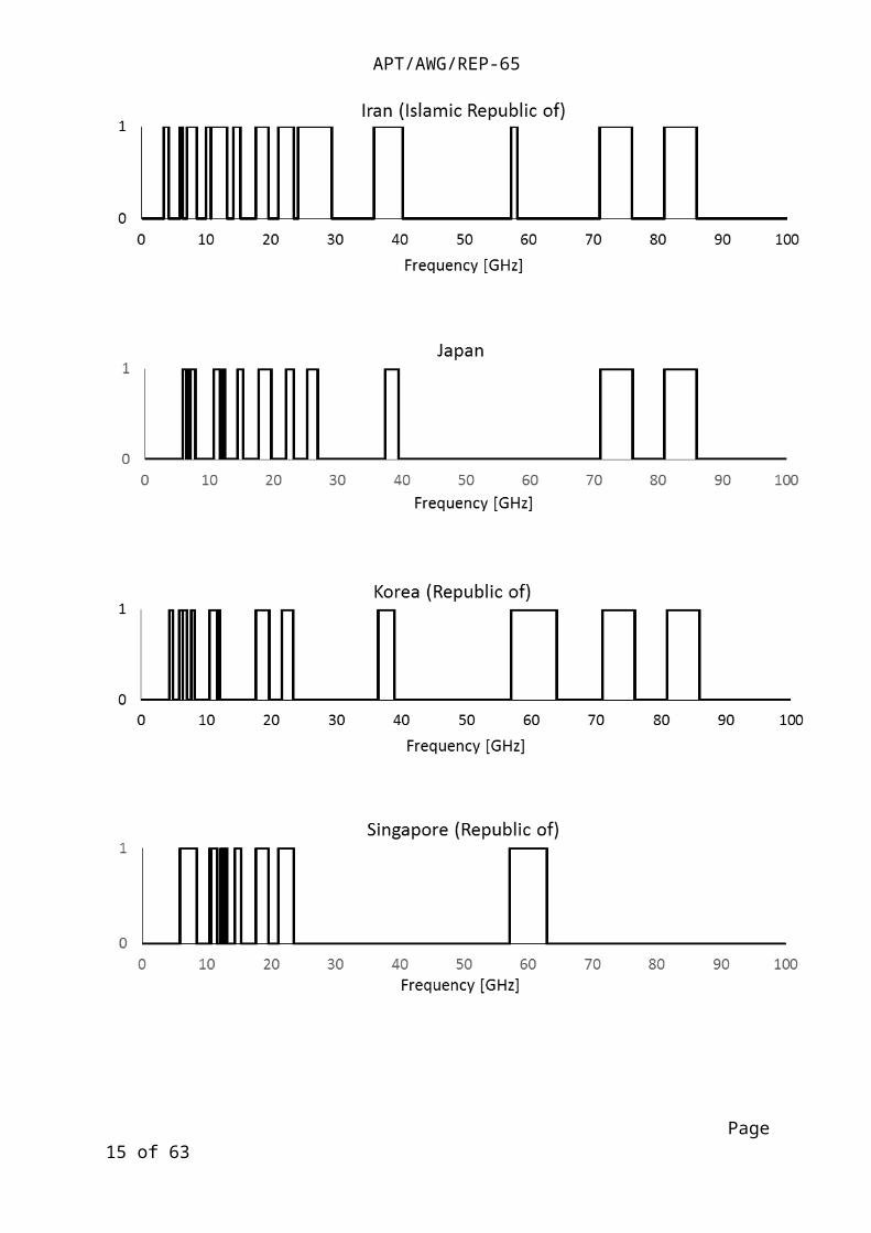
Graphs were made based on the data from Section 2.2 ‘Current status of FWS frequency in the Asia-Pacific region’ of survey report (APT/AWG/REP-54). For ‘assigned frequency range’, a value of 0 in the y-axis means frequency is not assigned, while a value of 1 means frequency is assigned.
Assigned frequency range
For Australia, Iran (Islamic Republic of), Japan and Korea (Republic of), the assigned frequency range for FWS is scattered from 2 GHz to 100 GHz. For China Mobile, China Telecom and China Unicom, it is assigned in 4 frequency bands. For Singapore (Republic of), Thailand and Socialist Republic of Vietnam, frequencies above 63 GHz are not assigned for FWS. Additionally for Thailand and Socialist Republic of Vietnam, frequencies above 24 GHz are also not assigned to FWS.
Page 10 of 63

APT/AWG/REP-65
Page 11 of 63

APT/AWG/REP-65
Figure 1. FWS assigned frequency range of APT members
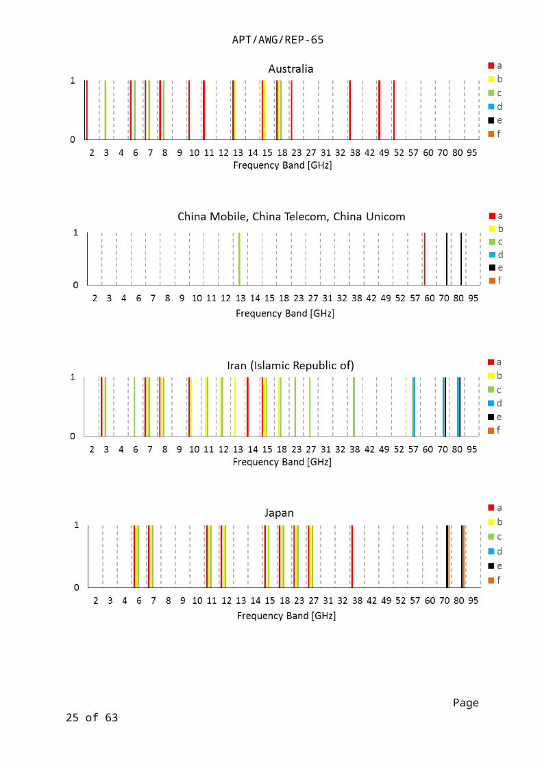
For the following graphs, the x-axis is divided into frequency bands defined in Section 6.1.1 based on ITU Radio Regulations for region 3. For the y-axis, a value of 1 means the corresponding choice is used regardless of the number of times the choice was selected, while a value of 0 means it is not used. Furthermore, if the frequency band given by each country falls inside 2 frequency bands of Section 6.1.1, both frequency bands will contain the corresponding choice.
Utilization
For Australia, China Mobile, China Telecom, China Unicom, Iran (Islamic Republic of), Japan, Korea (Republic of), Thailand and Socialist Republic of Vietnam, some frequency bands have 2 or more utilizations. For Singapore (Republic of), in each frequency band, there is only 1 utilization.
The definitions of the legends in the graphs are as follows:
a. transport/trunking network (communications channel in the communications infrastructure)
b. FWA (a system that connects offices or homes directly with the provider wirelessly)
c. mobile backhaul (a communications channel that allows large amounts of data to be sent)
d. temporary network (wireless communications during emergency situations, etc.)
e. others
Page 12 of 63

APT/AWG/REP-65
Page 13 of 63

APT/AWG/REP-65
Figure 2. FWS utilization of APT members
Licensing fee basis
Page 14 of 63
APT/AWG/REP-65
Basis for licensing fee varies per country. In addition to the choices, information below are given by each country.
In Australia, additional information can be found in here3.
For China Mobile, China Telecom and China Unicom, license fee is based on the function, for example XPIC, header compression, MPLS-TP, and so on.
In Japan, the licensee shall pay the license fee (spectrum user fee) every year. The licensee shall also pay the license application fee for application of the station. For frequencies not exceeding 6GHz, the amount of the license fee per station depends on frequency range, frequency bandwidth, transmitter output power, and site location. For frequencies exceeding 6GHz, the amount of the license fee is blanket per station. The amount of the license fee of the station for temporary networks or the station of FWA is cheaper than those of other stations.
In Korea (Republic of), additional information can be found in Enforcement ordinance of Radiocommunication Act.
In Singapore (Republic of), exclusive use and shared use of frequencies are charged differently.
In Thailand, other parameters like number of transmitters and transmitting power level are included in the fee calculation.
In Socialist Republic of Vietnam, the licensee has to pay the spectrum usage fee annually. The spectrum usage fee depends on frequency band and channel bandwidth. The licensee also has to pay the application fee per license.
The definitions of the legends in the graphs are as follows:
a. bandwidth regardless of frequency
b. frequency band
c. fee is increasing if you use multiple polarization wave
d. Location of radio stations
3 http://www.acma.gov.au/Industry/Spectrum/Radiocomms-licensing
http://www.acma.gov.au/Industry/Spectrum/Radiocomms-licensing/Apparatus-licences
http://www.acma.gov.au/Industry/Spectrum/Radiocomms-licensing/Class-licences
http://www.acma.gov.au/Industry/Spectrum/Radiocomms-licensing/Spectrum-licences
http://www.acma.gov.au/theACMA/About/Making-payments/Apparatus-licence-fees/apparatus-licence-fees-acma
Page 15 of 63

APT/AWG/REP-65
Page 16 of 63

APT/AWG/REP-65
Figure 3. FWS licensing fee basis of APT members
Other data such as bandwidth, number of stations and maximum transmitter power can be found in the survey report on FWS (APT/AWG/REP-54). In particular, for 57 GHz and above, the bandwidth is 100 MHz or higher. Number of stations and maximum transmitter power are hard to compare due to lack of data.
6.1.3. Utilization of FWS and network characteristics of each country
The tables below list the utilization of FWS spectrum of each country based on the data from Section 2.3 ‘Utilization of FWS spectrum’ of survey report (APT/AWG/REP-54).
The first table shows the utilization with expanding market trends, followed by a table showing utilization with shrinking market trends and then a table showing utilization with stable market.
Expanding market trends
Page 17 of 63

APT/AWG/REP-65
Countries with expanding market trends
Utilization Application
China Mobile, China Telecom, China Unicom
FWA LTE carrier,
mobile backhaul
Small cell
Iran (Islamic Republic of) Transport/trunking network Transport/trunking network
FWA FWA such as Data transmission
Mobile backhaul Mobile backhaul
Japan FWA FWA
Mobile backhaul Mobile backhaul
Temporary network Disaster recovery
Korea (Republic of) Transport/trunking network P2P communication
Shrinking market trends
Countries with shrinking market trends
Utilization Application
Japan Transport/trunking network transport/
trunking
network for telecommunications carrier
Stable market trends
Countries with stable market
Utilization Application
Japan FWA FWA
Mobile backhaul Mobile backhaul
Temporary network Disaster recovery
Others Public and general services
Socialist Republic of Vietnam
Transport/trunking network Transport/trunking network
Mobile backhaul Mobile backhaul
Graphs below were made based on the data from Section 2.2 ‘Current status of FWS frequency in the Asia-Pacific region’ of survey report (APT/AWG/REP-54). For the following graphs, the x-axis is divided into frequency bands defined in Section 6.1.1 based on ITU Radio Regulations for region 3. For the y-axis, a value of 1 means the corresponding choice is used regardless of the number of times the choice was selected, while a value of 0 means it is not used. Furthermore, if the frequency band given by each country falls inside 2 frequency bands of Section 6.1.1, both frequency bands will contain the corresponding choice.
Page 18 of 63

APT/AWG/REP-65
Transmission rate
For China Mobile, China Telecom, China Unicom, Korea (Republic of), Iran (Islamic Republic of) and Japan, above the 60 GHz band, transmission rates of more than 500Mbps (letters d, e, f) are used. For other frequency bands, less transmission rates are assigned. There is no data given for Singapore (Republic of) and Thailand. The definitions of the legends in the graphs are as follows:
a. below 50 Mbps
b. 51-100 Mbps
c. 101-500 Mbps
d. 501-1000 Mbps
e. 1001-2000 Mbps
f. above 2000 Mbps
Page 19 of 63

APT/AWG/REP-65
Figure 4. FWS transmission rate of APT members
Type of network
Most networks are P-P and are not dependent on frequency bands. In Singapore (Republic of), there is also MP-MP networks. There is no data given for Thailand.
The definitions of the legends in the graphs are as follows:
a. P-P Network
b. P-MP Network
c. MP-MP Network
Page 20 of 63

APT/AWG/REP-65
Page 21 of 63

APT/AWG/REP-65
Figure 5. FWS type of network of APT members
6.2. Trends concerning standardization and regulation for FWS
6.2.1. Methods for frequency assignment and licensing of FWS in each country
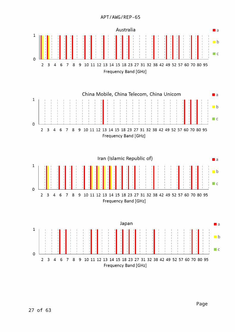
Graphs were made based on the data from Section 2.2 ‘Current status of FWS frequency in the Asia-Pacific region’ of survey report (APT/AWG/REP-54). For the following graphs, the x-axis is divided into frequency bands defined in Section 6.1.1 based on ITU Radio Regulations for region 3. For the y-axis, a value of 1 means the corresponding choice is used regardless of the number of times the choice was selected, while a value of 0 means it is not used. Furthermore, if the frequency band given by each country falls inside 2 frequency bands of Section 6.1.1, both frequency bands will contain the corresponding choice.
Ways of assigning frequency
Page 22 of 63

APT/AWG/REP-65
The most common way to assign frequency is first come first served (letter a). For China Mobile, China Telecom and China Unicom, assignment through comparative inspection (letter c) is used, while in Iran (Islamic Republic of), it mostly uses other methods (letter d).
The definitions of the legends in the graphs are as follows:
a. first come first served
b. auction
c. assignment through comparative inspection
d. others
Page 23 of 63

APT/AWG/REP-65
Page 24 of 63
APT/AWG/REP-65
Figure 6. FWS ways of assigning frequency of APT members
Licensing
The most common licensing scheme is individual licensing (letter a). Light licensing (letter b) is used in China Mobile, China Telecom, China Unicom and Korea (Republic of) while license free (letter c) is also used in Korea (Republic of).
The definitions of the legends in the graphs are as follows:
a. individual licensing
b. light licensing (definition given by ECC Report 80)
c. license free
d. others
Page 25 of 63

APT/AWG/REP-65
Page 26 of 63
APT/AWG/REP-65
Figure 7. FWS licensing of APT members
6.2.2. Standardization activities concerning FWS in each country
The table below summarizes the international standardization activities of each country. The organization that handles these activities are also listed together with the standards and guidelines for fixed wireless.
Country Participation in
international standardizatio
n activities
Organization that handles
standardization, guidelines, and/or
systems concerning fixed wireless
Standards, guidelines and/or systems for fixed wireless
Australia ITU
APT
None None
Iran (Islamic Republic of)
No Yes. Communications Regulatory Authority
Yes. As provided by ITU Recommendations F-series and well-known standardization organizations.
Page 27 of 63

APT/AWG/REP-65
Japan MIC is involved in ITU and APT. Industrial organizations are involved in IEEE.
Fixed Radio Communications Division (in principle)
Yes (Ordinance Regulating Radio Equipment (Radio Regulatory Commission Rules No. 18 of 1950) and relevant regulations)
Korea (Republic of)
No MSIP(Ministry of Science, ICT and Future Planning)
Rules on Radio Equipment
Technological standards for Radio Equipment
Singapore (Republic of)
No None
Thailand Office of The National Broadcasting and Telecommunications Commission (NBTC)
Telecommunications Standard and Technology Bureau
87 Phaholythin 8 (Soi Sailom), Samsen Nai, Phayathai, Bangkok 10400. Thailand
Tel : +66 2271 - 0151 - 60 - 654, Call Center : 1200 (Press 2)
Fax : +66 2271 - 3518
1. Notification of the National Telecommunications Commission
On radio frequency plan
Re: radio frequency plan for fixed service frequency range 5 GHz )NTC. FP 106-2550(
2. Notification of the National Telecommunications Commission
On radio frequency plan
Re: radio frequency plan for fixed service frequency range 6.7 GHz )NTC. FP 107-2550(
3. Notification of the National Telecommunications Commission
On radio frequency plan
Re: radio frequency plan for fixed service frequency range 7.2 GHz )NTC. FP 108-2550(
4. Notification of the National Telecommunications Commission
On radio frequency plan
Re: radio frequency plan for fixed service frequency range 7.5 GHz )NTC. FP 109-2550(
5. Notification of the National Telecommunications Commission
Page 28 of 63

APT/AWG/REP-65
On radio frequency plan
Re: radio frequency plan for fixed service frequency range 8 GHz) NTC. FP 110-2550(
6. Notification of the National Telecommunications Commission
On radio frequency plan
Re: radio frequency plan for fixed service frequency range 11 GHz )NTC. FP 111-2550 (
7. Notification of the National Telecommunications Commission
On radio frequency plan
Re: radio frequency plan for fixed service frequency range 15 GHz )NTC. FP 112-2550 (
8. Notification of the National Telecommunications Commission
On radio frequency plan
Re: radio frequency plan for fixed service frequency range 18 GHz) NTC. FP 113-2550(
9. Notification of the National Telecommunications Commission
On radio frequency plan
Re: radio frequency plan for fixed service frequency range 23 GHz) NTC. FP 114-2550(
Socialist Republic of Vietnam
Yes, we are participating in ITU-R.
Organization: ARFM - MIC
Ministry of Information and Communication approves the technical standards, does the type approval.
Yes
Technical standards, Spectrum plan, Channel arrangement for fixed service
Ref: http://www.mic.gov.vn; http://www.cuctanso.vn
6.3. FWS Technology trends
6.3.1. Technology development in each country
The tables below list the frequency range, bandwidth, transmission rate and target application of countries currently conducting research and development in the fixed wireless field. These are China Mobile, China Telecom, China Unicom, Iran (Islamic Republic of), Japan and Korea (Republic of).
Page 29 of 63

APT/AWG/REP-65
China Mobile, China Telecom, China Unicom
Frequency
range
[GHz]
Bandwidth
[MHz]
Transmission rate
[Mbps]Target application
171-76 GHz
81-86 GHz
250
500
750
4000 Mobile backhaul
Iran (Islamic Republic of)
Frequency range
[GHz]
Bandwidth
[MHz]
Transmission rate
[Mbps]Target application
1 60 - - -
2 24- 24.250 250 750 Data transport
Japan
Frequency
range
[GHz]
Bandwidth
[MHz]
Transmission rate
[Mbps]Target application
1 70/80 4500 6Gbit/s
Inter-building private networks,
Disaster recovery, mobile
backhaul connectivity (last-mile access link) etc
2 90 5000 10Gbit/s
Fixed Wireless System with
Agile Deployment Capability
using Optical and
Millimeter-wave Communication
Korea (Republic of)
Frequency
range
[GHz]
Bandwidth
[MHz]
Transmission rate
[Mbps]Target application
1 71-76/81-86 5000 5000 Mobile backhaul/fronthaul
Page 30 of 63

APT/AWG/REP-65
2 17.7-19.9 112 1000 Mobile backhaul
6.3.2. Recent trends in each country
The table below summarizes information about particular technologies and technology trends about fixed wireless transmission of each country.
Country References where there is information about
network architecture, antennas, transmission method, use of high
frequencies, etc.
Plans to conduct research about
network architecture, antennas,
transmission method, use of high frequencies
in fixed wireless transmission
(yes/no)
Information or technology trends
about fixed wireless transmission
China Mobile, China Telecom, China Unicom
yes Frequency band ranging from 57 GHz to 64 GHz (V-BAND) is tailored for service backhaul for small cell base stations that are deployed on buildings or at the street level.
Frequency bands ranging from 71-76 GHz or 81-86 GHz (E-BAND) can provide large-capacity backhaul microwave links or aggregation links on a mobile communications network or a private network, or replace optical fibers to transmit CPRI signals between baseband units (BBUs) and remote radio units (RRUs) in a distributed base
Page 31 of 63

APT/AWG/REP-65
station system to achieve longer transmission of RRUs.
Iran (Islamic Republic of)
This administration looks for technologies which are able to enable spectrum users to utilize frequency channels in share within same geographical area, automatically.
Japan AWG-16/INP-43 “Introduction of High-capacity E-band Fixed Wireless System Using Impulse Radio Technology”
AWG-16/INP-59 “ Fixed Wireless Systems Using Millimeter Wave”
http://www.toshiba.co.jp/tech/review/2011/12/66_12pdf/f02.pdf
http://www.toshiba.co.jp/rdc/detail/1111_01.htm
NEC TECHNICAL JOURNAL Vol.8 No.2 (April, 2014) “Development of the iPASOLINK, All Outdoor Radio (AOR) Device “, “Development of iPASOLINK Series and Super-Multilevel Modulation Technology “, “Ultra-High-Capacity Wireless Transmission Technology Achieving 10 Gbit/s Transmission “
yes Some companies develop element technology applicable to the fixed wireless systems.
For example, the transmitting and receiving filters with narrow band characteristic and low insertion loss have been developed to use a high temperature superconducting materials.
Korea (Republic of)
N/A yes N/A
Singapore (Republic of)
N/A no Nil
Page 32 of 63

APT/AWG/REP-65
Thailand Thailand is planning to assign frequencies in the band 71-76 GHz and 81-86 GHz (E-band).
Socialist Republic of Vietnam
yes
6.4. Analysis of present demands and future usage for FWS
6.4.1. Demands for FWS based on current utilization
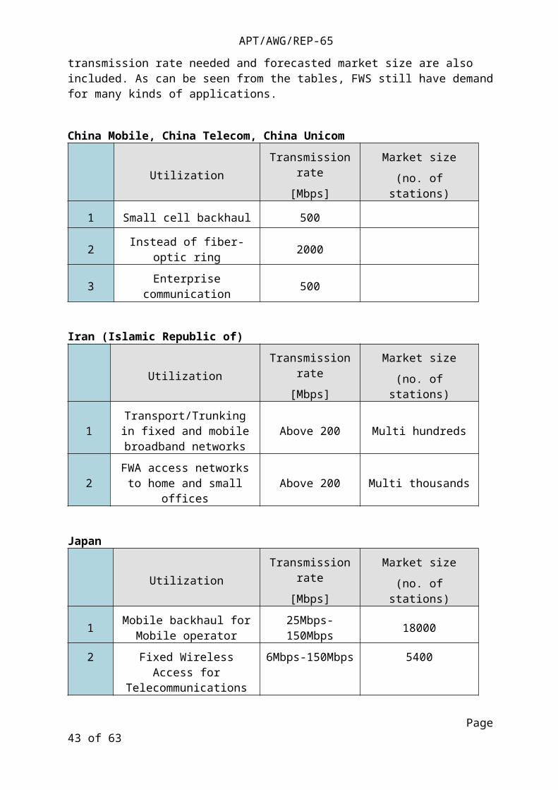
The tables below list the kinds of utilizations of fixed wireless systems expected in each country. In addition, the transmission rate needed and forecasted market size are also included. As can be seen from the tables, FWS still have demand for many kinds of applications.
China Mobile, China Telecom, China Unicom
UtilizationTransmission rate
[Mbps]
Market size
(no. of stations)
1 Small cell backhaul 500
2 Instead of fiber-optic ring 2000
3 Enterprise communication 500
Iran (Islamic Republic of)
UtilizationTransmission rate
[Mbps]
Market size
(no. of stations)
1Transport/Trunking in fixed
and mobile broadband networks
Above 200 Multi hundreds
2 FWA access networks to home and small offices Above 200 Multi thousands
Japan
UtilizationTransmission rate
[Mbps]
Market size
(no. of stations)
1 Mobile backhaul for Mobile operator 25Mbps-150Mbps 18000
Page 33 of 63

APT/AWG/REP-65
2 Fixed Wireless Access for Telecommunications carrier 6Mbps-150Mbps 5400
Korea (Republic of)
UtilizationTransmission rate
[Mbps]
Market size
(no. of stations)
1 Mobile Backhaul 1000 -
2 Mobile Fronthaul 3000 -
Thailand
UtilizationTransmission rate
[Mbps]
Market size
(no. of stations)
1 Mobile Backhaul
2 Wireless Local Area Network
Socialist Republic of Vietnam
UtilizationTransmission rate
[Mbps]
Market size
(no. of stations)
1 transport/trunking network N x 155 500
2 mobile backhaul 34 – 155 20 000
6.4.2. Future usage plan for FWS and consideration for possible new usages
The tables below show the planned frequency ranges, utilization and time planning of Australia, Iran (Islamic Republic of), Japan, Singapore (Republic of), Thailand and Socialist Republic of Vietnam. The planned utilization is mostly for FWA and fixed service.
The last table summarizes each countries preferable frequency range and fixed systems. The definition of the letters for ‘preferable fixed systems in own country in the future’ are
a. Fixed wireless transmission will be the priority use.
b. Fiber-optic transmission will be the priority use if fiber-optic cable could be laid.
c. Use each method depending on purposes. (Please write examples for each use.)
d. Others (Please write examples specifically.)
Based on the inputs from each country, the preferable fixed systems in the future are ‘b’ or ‘c’.
Australia
Page 34 of 63

APT/AWG/REP-65
Frequency range
[GHz]Utilization Time planning Plan or
possibility
1 3.4–3.6 FWA 2014—currently reviewing use Possibility
Iran (Islamic Republic of)
Frequency range
[GHz]Utilization Time planning Plan or
possibility
1 24- 24.250 FWA2014/8 assignment
2014/12 in operationPlan
2
Some TDD LTE
frequency bands (under
study)
FWA to access part of networks 2014/2015 Plan
Japan
Frequency range
[GHz]Utilization Time planning Plan or
possibility
1
22.14-22.98
25.27-26.98
38.06-39.48
FWA
Aug. 2014: Study
technical requirements in order to introduce
technical standards for FWA systems which
use two neighboring
frequency blocks to
transmit a carrier wave.
Possibility
Singapore (Republic of)
Frequency range
[GHz]Utilization Time planning Plan or
possibility
1 28 Fixed services Possible
2 70/80 Fixed services Possible
Page 35 of 63

APT/AWG/REP-65
Thailand
Frequency range
[GHz]Utilization Time planning Plan or
possibility
1 71-76, 81-86 (E-band)
Mobile backhaul, Wireless local area
network, etc.
2014: regulations
2015: assignmentPlan
Socialist Republic of Vietnam
Frequency range
[GHz]Utilization Time planning Plan or
possibility
1 60 – 70 Transport / Backhaul 2018
Country
Preferable frequency range for fixed wireless
transmission and its reason
Preferable fixed systems in own country in the future
Choice Specifics
Australia Above 6 GHz preferred for point-to-point systems.
Depends on circumstance, driven by geography, population density and distribution.
Iran (Islamic Republic of)
b
Japan FWS below 6GHz can achieve over 50-km-long hop distance, and they are mainly suited for trunk/trunking network.
FWS from 10GHz to 30GHz can transmit from several km to over 10km, and they are mainly suited for various applications including mobile backhaul.
c Telecommunications carrier sometimes use wireless in rural areas because of cost. They also use wireless for backup of communication links during emergency situations.
The national government, local government and some business operators such as the power industry have fixed wireless network for communications during emergency situations or for each business use.
Page 36 of 63

APT/AWG/REP-65
FWS over 30GHz can transmit from several hundred m to several km, and they are suited for high-capacity transmission.
In Japan, we use different ways based on the characteristics of the band. We are expanding the use of millimeter band such as 70/80GHz and developing millimeter band such as 120GHz for expanding transmission capacity because of traffic explosion and expansion of high-definition television.
Korea (Republic of)
N/A c To enhance the capacity of radio access, small-cells will be more used in the future. One of the major challenges to deploying small cells is mobile backhaul and fronthaul. Mobile backhaul is the network which is connecting a base station and core network such as backbone. And, mobile fronthaul is the network connecting RRH (Remote Radio Head) and digital centralized unit such as BBU (BaseBand Unit) for effective management between cells. To install the cost-effective network consisted of small cells, not fiber-optic cable but also wireless FWS might be preferred in the area where the fiber-optic cable could not be laid due to the installation difficulty or cost.
Page 37 of 63

APT/AWG/REP-65
<Wireless Mobile Backhaul/Fronthaul Concept>
<Market Trend of FWS>
Singapore (Republic of)
Sub 10 GHz
Higher frequencies are more susceptible to rain fade.
b
Thailand Internationally harmonized frequency bands would be preferred because of economies of scale and availability of equipment.
c
The choice of technology will depend on each user’s requirements and circumstances. For example, fiber-optic systems will be preferred for a highly reliable transmission if fiber-optic cables could be laid, whereas fixed wireless systems may be used where fiber-optic installation is not feasible.
Socialist Republic of Vietnam
FWS below 15GHz can achieve long hop distance, and they are mainly suited for transport/trunking network.
FWS from 15GHz to 23GHz can transmit from several km, and they are mainly suited for mobile backhaul.
The band 18 GHz has big difficulty due to high rain attenuation level.
b
Answer is b but Fixed wireless transmission will be the priority use for the new and small mobile operators.
7. Progress of technology and industry to support Fixed Wireless System future trends
Page 38 of 63

APT/AWG/REP-65
7.1. Transceiver Technologies
Recommendation ITU-R F.1101 covers some of the technologies used in the present FWS. The technologies widely used in the present FWS are as follows.
– Multi-level QAM.
– XPIC (Cross Polarization Interference Canceller).
– Equalizer.
– FEC (Forward Error Correction).
– ATPC (Automatic Transmit Power Control).
– ACM (Adaptive Code and Modulation).
7.1.1. Multi-level QAM
Multi-level QAM and XPIC are used to maximize the frequency usage efficiency of FWS.
QPSK and multi-level QAM from 16-QAM to 256-QAM are generally adopted for a modulation scheme for FWS. Progress in semiconductor devices now enables us to employ 1 024 QAM and work up to 4096 QAM. However, the higher-order modulation requires an even higher carrier to noise ratio (CNR). Moreover, the use of 1 024 QAM increases the data rate only by 1.25 compared with 256 QAM. 1 024 QAM modulation schemes and above are not widely used, and they are foreseen to be limited when adaptive modulation is concerned.
7.1.2. XPIC
Polarization multiplexing is another way to increase the capacity without bandwidth expansion. However, interference between the two polarizations causes some degradation of BER performance, especially when using high multilevel modulation schemes. This interference can be cancelled by reproducing the “interference condition at the channel” in the demodulator. XPIC generates a replica of interference from the orthogonal polarization, allowing its output to be “subtracted” (or effectively cancelled) from the received signal.
7.1.3. Equalizer
FWSs often employ adaptive equalization as a counter measure against distortions due to frequency selective fading, and in order to compensate for imperfections in hardware. The equalizers contribute to not only performance improvement but also equipment cost reduction, because introduction of the equalizer enables the use of less expensive RF devices. Generally, an adaptive time domain equalizer (ATDE) is adopted. There are two types for the configuration: One is a Linear Equalizer (LE) using finite impulse response (FIR) filters and the other is a Decision Feedback Equalizer (DFE) with two FIR filters.
7.1.4. FEC
FEC can reduce BER performance degradation from various causes. Among the error correcting codes available for FWS, the most popular is Reed-Solomon code. Sometimes, a coded modulation scheme such as TCM (Trellis Coded Modulation) is applied. Today, more powerful codes, such as low-density parity-check (LDPC) code, which is based on iterative decoding, are being adopted.
7.1.5. ATPC
Page 39 of 63

APT/AWG/REP-65
When ATPC is implemented on a FWS link4 , a transmitter on that link may operate at a reduced power under favourable propagation and operating conditions. Clearly, a transmitter using ATPC will produce less interfering power than a transmitter operating at the maximum power. Different administrations may impose different limitations on the implementation of ATPC, and these limitations may depend on whether multipath fading or rain fading is the dominant performance impairment in a particular frequency band.
In a typical implementation of ATPC, the Received Signal Level (RSL) is monitored at the receiver and sent to the transmitter. When the RSL falls by a prescribed amount below its expected level, the transmitter increases its power to partially offset further reductions in RSL. All of these considerations may need to be taken into account in the frequency coordination of the link. The use of higher frequency bands, when rain attenuation is important, is increasing. It will be important to quantify how the implementation of ATPC will facilitate sharing with other services in these frequency bands.
7.1.6. ACM
ACM is used for changing the modulation schemes and coding rates according to the channel condition, such as rain. FWS are increasingly used for data transmission, and the capacity levels therefore do not need to correspond exactly to the legacy circuit switching interface. This allows the capacity to be varied by changing the modulation schemes and coding rates according to the channel condition. In this way, it is possible to ensure that the most important signals can survive, even under severe conditions by allowing a down shift of modulation. Although this comes with a reduction in capacity, the alternative would have been a complete loss of communications on the link. This approach is interesting when coupled with IP/Ethernet traffic dynamic capacity control, where different QoS priorities are given to differently important traffic and where non-essential traffic can be momentarily lost without impacting services supported by the FWS.
Used with or without ACM, dynamic traffic capacity management is useful when transporting traffic based on IP data transmission. As mentioned above, this allows prioritizing the transport of some traffic over others, providing additional reliability for some services more sensitive to packet loss. In bands above 60 GHz, where very large bandwidth are possible, in the order of 1 GHz or more, the technology might not accommodate very high modulation formats over most links for lack of sufficient fade margin for guaranteeing commonly expected availability. Present equipment operate on no more than 2 or 4 states modulation formats and 16/32 QAM will already be a challenge for the future. For this reason also a different adaptive methodology, referred as “band adaptive systems”, might also be employed. During adverse propagation, the system extends the receiver BER threshold, for a portion of the payload, reducing the bandwidth rather than dropping the modulation level. In this way longer links may also be covered with satisfactory capacity/quality trade off.
7.2. Antennas
7.2.1. Passive antenna
In microwave systems (10GHz - 42GHz), parabolic antennas with diameters of 1ft to 10 ft are being used. In general, the antenna diameter used in each frequency band is shown in Fig.8. On the other hand, in the E-band, whose use is recently starting, 1 to 2 ft of antenna diameters are
4 The advantages of using ATPC are limited when not used by a majority of links in a geographical area.
Page 40 of 63

APT/AWG/REP-65
being used. The beamwidth of a 2 ft E-band antenna is around 0.5 degrees. A diameter larger than 2 ft will lead to a sharper beamwidth which will make antenna alignment very difficult.
Dia.(ft) 10 11 13 15 18 23 26 28 32 38 42 8012346810
Frequency Band (GHz)
Figure 8. Antenna diameter for point to point radio systems
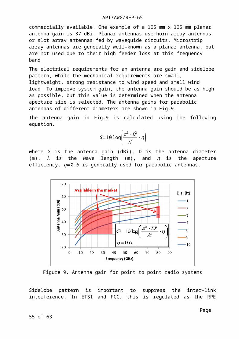
In the unlicensed 60GHz band, it has been noted that link distance cannot be long due to the large attenuation of oxygen at this frequency. It is therefore mainly being used for transmission between small cells separated several hundred meters apart. For this reason, antennas with small diameters are also being used. In small cells, easy installations on lamp posts etc. are required. Therefore, planar antennas integrated into radio equipment are also being deployed. Furthermore, since planar antennas are usually integrated into radio equipment, standalone planar antennas at 60 GHz are usually not commercially available. One example of a 165 mm x 165 mm planar antenna gain is 37 dBi. Planar antennas use horn array antennas or slot array antennas fed by waveguide circuits. Microstrip array antennas are generally well-known as a planar antenna, but are not used due to their high feeder loss at this frequency band.
The electrical requirements for an antenna are gain and sidelobe pattern, while the mechanical requirements are small, lightweight, strong resistance to wind speed and small wind load. To improve system gain, the antenna gain should be as high as possible, but this value is determined when the antenna aperture size is selected. The antenna gains for parabolic antennas of different diameters are shown in Fig.9.
The antenna gain in Fig.9 is calculated using the following equation.
G=10 log( π2 ∙ D2
λ2 ∙ η)where G is the antenna gain (dBi), D is the antenna diameter (m), λ is the wave length (m), and η is the aperture efficiency. η=0.6 is generally used for parabolic antennas.
Page 41 of 63

APT/AWG/REP-65
Figure 9. Antenna gain for point to point radio systems
Sidelobe pattern is important to suppress the inter-link interference. In ETSI and FCC, this is regulated as the RPE (Radiation Pattern Envelope). By reducing the sidelobe, inter-link interference can be suppressed, and then frequency utilization in terms of frequency reuse in a certain area can be more efficient. In ETSI, RPE is ranked according to Class1, Class2, Class3 or Class4. Currently, Class2 or Class3 are mainly used, but there are also some movement that encourage the use of Class4 to suppress more interference and increase frequency utilization efficiency. The RPE standard of ETSI is shown in Fig.10.
Figure 10. ETSI Radiation pattern envelope (Range 4: 24GHz-30GHz)
Another kind of antenna is a wideband millimeter-wave substrate integrated waveguide slotted narrow-wall fed cavity antennas. This antenna consists of a feeding SIW and a slotted narrow-wall fed high permittivity dielectric loaded substrate integrated cavity (SIC) in a co-planar configuration. First, the cavity modes are analyzed for selecting the feeding structure. Then, the equivalent circuit of the feeding structure is formulated to reveal the mechanism of wideband
Page 42 of 63
APT/AWG/REP-65
operation of the proposed antenna. The antennas and arrays operating at 35 and 60 GHz bands fabricated with printed circuit board (PCB) technology are exemplified to validate the concepts. The prototypes with single cavity achieve a bandwidth of 10% for 15-dB return loss and gain of 6 dBi at both 35 GHz and 60 GHz. The 2 x 2 35-GHz SIC antenna array shows a bandwidth of 11.7% for 15-dB return loss and gain of up to 10.8 dBi. The SIW-fed SIC millimeter-wave antenna arrays feature a wideband operation with low loss, low cost, low profile, easy integration configuration.
7.2.2. Active antenna
Near future evolution in the antenna technology may be related to the deployment of new mobile access networks, LTE and 4G, which will use smaller size cell footprint, especially in urban areas, the backhauling will require denser and shorter link networks. For active antenna systems used in base stations of IMT systems, Report ITU-R M.[IMT-ANTENNA] addresses several aspects of these systems. In addition, equipment may be installed on light poles at street level and shall not have a large visual impact. This will drive the use of smaller antenna which would likely be integral to the equipment itself. This could highly help in link activation and to compensate slight modification in pointing due to pole vibrations and bending due to various unpredictable reasons (road works, car accidents, …); it could possibly help in reducing effect of multipath reflections from buildings nearby.
The consequent loss of directivity might be compensated using steering antenna as shown in Fig.11, which can keep pointing in an adaptive way even in an urban and changing environment where the pole can be bent causing pointing misalignment.
Figure 11. Antenna with steering beam (both transmitting and receiving)
Furthermore, active antennas may also be driven by “beam-forming” algorithms as shown in Fig.12 for minimising interference, i.e. minimizing the gain in the direction of higher interference eventually detected. This might become of major interest in dense urban environment for street level base station backhauling where reflection/diffraction phenomena is of importance.
Page 43 of 63

APT/AWG/REP-65
Figure 12. Antenna with beamforming capability (both transmitting and receiving)
7.3. Network architecture (Technologies)
[In this section, texts may be transferred from Report ITU-R F.2323. Also, contents from the Working document towards a preliminary draft new Report ITU-R M.[IMT.ARCH] and/or ITU-R F.[FS IMT/BB] will be used.]
7.4. Technologies for achieving high data rates
7.4.1. Impulse Radio
Impulse Radio (IR) Features
IR technology is being studied as one of the possible Ultra Wide Band (UWB) system and is expected to apply widely not only to high speed communication, but also for high precise ranging system and short range radar and so on.
IR technology eliminates the need for an up-and-down converter composed of modem, oscillator, multiplier and mixer, which is used in the conventional radio technology, and allows for a simple configuration, facilitating size reduction, low power consumption and low delay. Therefore millimeter-wave band allocating wide frequency band in radio regulation rule is very suitable to use for this application.
Basic Principle of Impulse Radio (IR)
An impulse is an ultra-short pulse in time domain and has low to high (>100 GHz) line spectrum in the frequency domain. In IR systems, modulation uses simple On-Off Keying (OOK) (ON=”1”, OFF=”0”) and in the transmit end, impulse signal responding to the input “1” is generated by using the ultra-short pulse generation. Band pass filter (BPF) filters the impulse signals and extracts the E-band spectrum to transmit wave packets. For a transmit frequency at 80 GHz (81 to 86 GHz), BPF bandwidth is set to 5 GHz. In the receiver end, “1”signal is detected by envelopes of wide-band impulse signals from wave packets. Fig.13 shows the basic principle of IR technology
Page 44 of 63

APT/AWG/REP-65
Figure 13. Principle of impulse radio technology
Towards Higher Capacity Radio
Using IR equipment, parallel transmission application is possible to increase capacity up to 12 Gbit/s by using 4 lanes system. RF interference can be avoided by employing optimum combination of both transmit-receive frequency and polarization. Fig.14 shows the 12 Gbit/s, 4 lanes system.
Figure. 14 12 Gbit/s, 4-lanes transmission system
Page 45 of 63

APT/AWG/REP-65
Furthermore, provided that more ultra-short pulse generation will be available, and 120 GHz band having more than 10 GHz frequency bandwidth be utilized, larger capacity transmission systems with more than 10 Gbit/s without parallel operation could be realized.
7.4.2. FWS using high frequency bands
7.4.2.1. FWS using millimeter wave
Features of the millimeter wave and wireless system
In the normal microwave communications bands (6 GHz to 42 GHz), the CS (Channel Separation) of one channel’s bandwidth is of a few dozen MHz, for example, 56 MHz maximum according to the European standard. It uses multilevel QAM (Quadrature Amplitude Modulation) as the modulation method. Thanks to recent improvements in digital signal processing and device technology, ultra-multilevel modulation as high as 2048 QAM is now available for practical use. If 2048 QAM is applied to 56 MHz CS, nearly 500 Mbps transmission capacity can be obtained.
As in Fig.15, the 60 GHz band has a unique feature: the oxygen in the air absorbs the electromagnetic energy and leads to greater losses for the transmitted signal. While this is viewed in standard communication systems as a disadvantage, in the case of small cell backhaul, it can be used as an advantage because there will be less interference between the links. Moreover, as the 60GHz band is designated as unlicensed band, anyone can deploy systems within that band. Having the signals more confined means there will be less interference and therefore an easier way to handle denser deployments. As the millimeter wave is of wider bandwidth, it is possible to use a lot of channels, and this matches the needs in small cell backhaul network environment.
Figure 15. Oxygen attenuation
Source: ITU-R P.676-10
Page 46 of 63

APT/AWG/REP-65
60GHz-band uses 50 MHz CS as its minimum unit and allows the selection of CS in integer-multiplied values. 80 channels can be used in the 59-63GHz band.
Figure 16. Examples of possible frequency slot arrangements in the band 57 - 64GHz
Source: ECC Recommendation (09)01
70/80GHz -band has a 10GHz bandwidth in total (5 GHz in one direction) and enables the use of up to 2 GHz CS, with 250 MHz CS as its minimum unit. Foreseeing the future congestion in the 70/80 GHz band, the standard for use of 62.5MHz CS (i.e. 1/4 of 250MHz) is under consideration in Europe. When standardization is completed, the current 19 channels of 250 MHz CS will be increased to 76 channels. In Japan, addition of 250MHz CS to the current 1000MHz CS as well as occupation of 5GHz band width is also considered.
Figure 17. Combining the channels from 71-76 / 81-86 GHz bands into a single FDD arrangement with duplex separation of 10 GHz
Source: ECC RECOMMENDATION (05)07 (Revised Dublin 2009 and Lugano 2013)
The millimeter wave wireless systems that have been put into practical use thus far typically employ a low-level modulation method that enables the configuration of a modulator/demodulator with analog circuitry at 1 GHz CS. The transmission capacity of this first-generation system is about 1 Gbit/s. To achieve higher capacity, it is necessary to apply multilevel QAM using digital circuitry. The development of this second-generation system using multilevel QAM was launched against this background around 2012, and systems that make 1Gbit/s transmission possible with 250 MHz CS and 64 QAM, are now about to be put into practical use. Equipment that can support beyond 25bps/Hz and radio link data rate of 10Gbit/s, is considered for development from now on, by increasing the frequency use efficiency by using XPIC and MIMO technologies. The modulation system, the data rate and the frequency use efficiency of the millimeter wave radio equipment are indicated in Fig.18.
Page 47 of 63

APT/AWG/REP-65
Figure 18. Millimeter wave wireless system technology trend
7.4.2.2. W-band wireless and radio-over-fiber links
W-band system architecture
Radiocommunication systems can provide agile deployment capability especially in particular locations such as mountains, valleys and rivers. Fig.19 shows a schematic concept of the seamless connections of wired and W-band wireless links. The W-band wireless link can be used as a backup, when the wired link is disconnected by disaster, accident, etc. The average data rate of the conventional wireless link is around a few Gbit/s, while the optical fiber communication can offer over 100 Gbit/s data transfer. Therefore, higher data rate by wireless technologies are required to mitigate surge of traffic demands in particular cases including disaster recovery phases. The W-band is more attractive for high-speed data transmission rather than microwave bands, because the wider frequency ranges are available in high frequency bands over 60GHz. In terms of atmospheric attenuation, the use of W-band (75–110 GHz) transmission appears to be suitable, as the attenuation within this band tends to be less than 1 dB/km. However, the attenuation increases largely under heavy rain conditions which limits the transmission length of the wireless link.
Page 48 of 63

APT/AWG/REP-65
Figure 19. Application of W-band wireless link to backup of optical link.
W-band radio access unit characteristics
Fig.20 shows a block diagram of W-band radio access unit which interfaces RoF link with W-band wireless link. The transmitter consists of a demultiplexer (DEMUX), two O/E converters, and RF components including a directional antenna, a bandpass filter (BPF), a power amplifier (PA) and a mixer (MIX). The DEMUX optically discriminate an LO signal in 1 and an IF signal in . The multiplier (MP) which is connected between the O/E converter and MIX doubles, triples or quadruples the detected frequencies. The IF signals are up-converted by a broadband MIX to W-band signals. The LO signal of the receiver is also supplied from the central station through an optical fiber. It is also multiplied by a MP and then supplied to a mixer to down-convert the received W-band signals to IF signals. The IF signals are then converted to optical carrier and transmitted to the central station through an optical fiber cable.
Transmitter
ReceiverFigure 20. Block diagram of W-band radio access unit.
The overall data transmission characteristics were evaluated using a symbol rate of 2.5 Gbit/s. Bit rate of QPSK and 16QAM modulated signals are 5 Gbit/s and 10 Gbit/s, respectively. Table shows EVM obtained when QPSK and 16QAM signals are transmitted through Tx and Rx units. Fig.21 shows constellation and spectrum of QPSK, 16QAM, 32QAM and 64QAM modulated signals. Although the constellations of 32QAM and 64QAM are degraded by the total RF performance, 10Gbit/s signal transmission using 16QAM was accomplished by the RF components described above.
Table EVM of QPSK and 16QAM signals vs input power of Rx unit.-60dBm -55dBm -50dBm -45dBm -40dBm -35dBm17.9%, 21.3%
14.5%, 17.1%
11.4%, 12.9% 9.6%, 11.4% 9.4%, 10.6% 9.8%, 10.8%
Page 49 of 63

APT/AWG/REP-65
Figure 21. Performance of constellation and spectrum of QPSK, 16QAM, 32QAM and 64QAM.
7.4.2.3. 120 GHz technology
This section provides an example of the performance of gigabit millimetre-wave links. Millimetre wave links are used for short-haul and high-capacity transmission because they use millimetre-wave bands and wide channel spacing. Their large bandwidth has been used to develop a high-capacity transmission system for mobile backhaul or local access networks that can transmit STM-4 (622 Mbit/s), or Gigabit Ethernet (more than 1 000 Mbit/s).
As of 2012, progress in high-speed devices has enabled the use of bands above 100 GHz for FS applications. Report ITU-R F.2107 describes a feasibility study of a 120 GHz band wireless link that employed ASK modulation scheme, and succeeded in transmitting 10-Gbit/s data over a distance of 5.8 km. 120-GHz-band wireless link equipment using QPSK modulation scheme has succeeded in 10-Gbit/s data transmissions over a short distance [H. Takahashi. et al., 2013]. Moreover, 20-Gbit/s data transmissions using polarization multiplexing using orthomode transducer have been reported [J. Takeuchi et al., 2012]. 10-Gbit/s bi-directional data transmission have been achieved by using 16 x 16-element planar slot array antenna [A. Hirata et al., 2013].
Studies of over-10 Gbit/s wireless transmission using millimetre-wave bands have been underway since 2010. Fig.22 shows the data rates of experimental millimetre-wave wireless links reported in various technical papers. Most of these reports described feasibility studies of indoor millimetre wave wireless links. Various types of over 10 Gbit/s wireless links have been reported, and this trend has become significant since 2010.
Page 50 of 63

APT/AWG/REP-65
Figure 22. Data rates of experimental millimeter-wave wireless links
These improvements in the millimetre-wave wireless link shown in Fig.22 were achieved by the introduction of high-order modulation scheme or the increase of bandwidth available with the use of higher frequency bands. These technologies are expected to be introduced into FWS in the near future. Gigabit operation in the 57-64 GHz range using high gain directional antenna arrays is also capable of providing multiple gigabit operation in support of point-to-point links using technologies such as IEEE Std 802.11ad.
7.4.3. Intra-frequency full duplex system
Introduction
Spectrum is a key precious resource in radio communication industry. One main purpose of radio communication technology evolution is to improve the spectrum efficiency. Intra-frequency full duplex (IFD) could double the spectrum efficiency by using the same frequency slot to transmit and receive signals simultaneously in the same channel.
As transmitting frequency and receiving frequency are within the same spectrum slots simultaneously, intra-frequency interference is the main problem of IFD systems. So the main purpose of system design is to reduce or eliminate this interference. A three-stage interference cancellation scheme is introduced and the system is showing in Fig.23.
Figure 23. IFD system with three-stage interference cancellation scheme
Page 51 of 63

APT/AWG/REP-65
Antenna isolation
As using one antenna to transmit and receive signals would only achieve 20~30 dB transmit-to-receive isolation, co-site antenna is used to provide more than 80dB transmit-to-receive isolation. This is convenient and economic. No extra antenna space is needed between the two antennas like MIMO needs.
RF/IF interference cancellation
Interference caused by transmitter at the receiver side can be offset by utilizing the existing transmitting signal with the same amplitude but opposite phase to cancel the interference. In RF/IF interference cancellation blocks, cancellation process is usually done in analog and passive device which can support good performance in SNR and linearity.
Baseband interference cancellation
DSP technology is used to eliminate the residual interference in baseband. Baseband digital interference cancellation process uses the same principle in RF/IF analog blocks described above but in digital domain. While in digital domain, enough delay can be provided to match the interference signal to the signal which is used to cancel it.
7.5. Device technologies
7.5.1. Superconducting bandpass filter
Future of the superconducting filter
Fig.24 shows superconducting applications. Superconducting materials have zero DC resistance characteristics.
Figure 24. Superconducting application
The superconducting application is divided into three fields: cable application, sensor application, and RF application. In RF applications, the most popular device is the superconducting filter. The superconducting filter has both low loss characteristics and sharp cut characteristics. Fig.25 shows the merits of the superconducting filter.
Page 52 of 63

APT/AWG/REP-65
Figure 25. Merits of superconducting filter
Wireless infrastructure with narrowband superconducting filters can reduce the guard band between systems. As a result, the wireless infrastructure can use wideband signals without distortion effects caused by other systems.
Basic of the narrowband superconducting filter
The filter consists of multiple resonators which decide what the filter will do. Superconducting resonators have high unloaded Q (Qu) value because superconducting materials have ultra-low loss characteristics in the RF range. The filter with sharp cut characteristics needs a large number of resonators. As a result, insertion loss of the filter is large. On the other hand, the superconducting filter with sharp cut characteristics can be realized with low insertion loss.
Superconducting transmitting filters with high power handling capability cannot be realized by conventional filter circuits, because the critical current characteristics of the superconductor materials determine the limit of the power handling capability characteristics. So we improved the filter circuit. The new filter concept is shown in Fig.26.
Figure 26. Concept of hybrid filter
Also a novel hybrid filter circuit is shown in Fig.27. The operation of each frequency band for the novel hybrid filter is shown in red arrows, blue arrows, and gray arrow. As a result, the high power signal at the center frequency does not pass thru the superconducting resonators (HTS reso.). The novel hybrid filter having only cavity resonators at the center frequency with high power handling capability can therefore be achieved.
Page 53 of 63

APT/AWG/REP-65
Figure 27. Novel hybrid filter circuit
7.5.2. EER Power amplifiers and the nonlinear distortion compensation technique
1 Operation Principle of an EER-PA
Fig.28 shows a block diagram of an EER-PA. In an EER-PA the efficiency can be improved by changing the supply voltage in accordance with the amplitude of the source signal. Fig.29describes why power supply dynamic control technique can achieve higher efficiency. In a conventional PA the drain voltage is constant and the amplitude waveform changes every moment. Transistors generate heat as shown in the red area of the upper part inFig.29. In a power supply dynamic control PA the drain voltage changes in accordance with the signal amplitude. Therefore transistors generate less heat than the conventional PA as shown in the red area of the bottom part inFig.29.
An input signal is separated into an amplitude modulated signal and a phase modulated signal. The phase modulated signal is then input to the RF-PA. On the other hand the amplitude modulated signal is input to the envelope modulator as shown inFig.28. The amplified amplitude modulated signal is used for the supply voltage of the RF-PA to recover the amplitude modulation. The efficiency of the EER-PA is better than the conventional PAs because the EER-PA can operate in the saturation region when the phase modulated signal is used. The efficiency of the EER-PA is defined as the multiplication of the efficiency of the RF-PA and that of the envelope modulator.
Page 54 of 63
APT/AWG/REP-65
Env.Det.
Div. Clipping
RF-PA
Env-AMP
EER-PA(Envelope Elimination & Restration - PA)
TXSig.
AM Sig.
PM Sig.
Figure 28 Block Diagram of an EER Power Amplifier
Drain Voltage
HeatOutput Signal Waveform
Heat
Drain Voltage
Output Signal Waveform
Conventional PA
Power Supply Dynamic Control PA
Figure 29 Comparison between Conventional PAs and Power Supply Dynamic Control PAs
Page 55 of 63

APT/AWG/REP-65
2 Problems of Power Supply Dynamic Control PAs
Power Supply Dynamic Control PAs have several problems to be solved. One is time misalignment between two paths, which degrades signal quality. The second one is nonlinearity. Fig.30shows the spectra of the input and output signal of a PA. The signal waveforms of the input and output signal of a PA are also shown in the nonlinearity affects the signal quality and also generates the signal leakage outside the designed frequency band. Compensation techniques such as digital pre-distortion (DPD) have to be used. ET and EER PA generate more complex nonlinearity than conventional PAs because of the non-ideal frequency characteristics of an envelope modulator like shown in Fig.32and the operation of the supply voltage modulation. As a result, ET and EER PA require a larger size of DPD algorithm such as Volterra type DPD to compensate for the complex nonlinearity.
Blue:Input Signal to a PARed:Output Signal from a PA
Figure 30 Power Spectra of the Input and Output signal of a PA
Blue:Input Signal to a PARed:Output Signal from a PA
Figure 31 Waveforms of the input and output signal of a PA
Page 56 of 63

APT/AWG/REP-65
Figure 32 Frequency Characteristics of the envelope modulator for the EER-PA
3 Simple Combined Compensation Technique for EER-PA
Fig.33 shows the block diagram for verifying the simple compensation technique. In the simple compensation technique it is assumed that RF-PA has nonlinear relationship between the drain voltage and AM-AM and between the drain voltage and AM-PM. It is also assumed that the envelope modulator has the frequency characteristics shown in Fig.31. Nonlinearity of the EER-PA can be compensated by combining the frequency characteristic compensation and memoryless nonlinearity compensation for the assumed EER-PA model.
Fig.34 shows the measured spectra when the simple combined compensation technique is used and when only memoryless DPD is used. By using the simple combined compensation technique. By using the simple combined compensation technique the nonlinear distortion can be compensated better than only memoryless DPD. The proposed technique was verified using measurements showing the feasibility of the approach
Figure 33 Block Diagram of the Simple Combined Compensation Technique
Page 57 of 63

APT/AWG/REP-65
-70
-60
-50
-40
-30
-20
-10
1992.5 2000.0 2007.5Frequency [MHz]
Pow
er s
pect
rum
[dB
m]
w/o freq. comp.& w/o DPD w/o freq. comp.
& w/ DPD
w/ freq. comp. & w/ DPD
Figure 34 Spectra of the Output Signal from the EER-PA
7.6. Propagation considerations
Because many FWS are point-to-point and use a line-of-sight link; it is important to consider the propagation model of point-to-point, line-of-sight links. Recommendation ITU-R P.530 provides guidance on prediction methods for the propagation effects that should be taken into account in the design of digital fixed line-of-sight links, both in clear-air and rainfall conditions, using the characteristics of rainfall given in Recommendations ITU-R P.837 and ITU-R P.838. It also provides link design guidance in clear step-by-step procedures, including the use of mitigation techniques to minimize propagation impairments. For the assessment of interference between the FS and other terrestrial services in the same band, Recommendation ITU-R P.452 should be used.
In order to plan and carry out interference assessment involving fixed service links in bands above 50 GHz, in particular, the 70/80 GHz and 90 GHz bands, the propagation characteristics regarding these bands are required. It has been noted that while there is some experimental data sets for the bands above 50 GHz, Recommendations ITU-R P.530, ITU-R P.837 and ITU-R P.838 can be used for this purpose. Regarding Recommendation ITU-R P.452, for evaluating interference between the FS and other terrestrial services in bands above 50 GHz, clear air conditions should be considered, as worst case, until this Recommendation is sufficiently tested for these bands. Therefore, further experimental data and studies would enhance these propagation models.
Page 58 of 63

APT/AWG/REP-65
The frequency bands for FWS links cover the range from below 1 GHz to millimetre-wave (up to 95 GHz). The propagation characteristics of SHF and those of millimetre waves are quite different because free-space loss is proportional to the square of the operating frequency; therefore, the free space loss in the millimetre-wave region is much higher than that in the SHF region. Report ITU-R F.2107 reports the relationship between the attenuation (dB/km) and the frequency (GHz) of radio waves due to gases and rain for radio transmission through the atmosphere. Fig.35 shows the attenuation due to gasses and hydrometeors for transmission through the atmosphere. In the SHF region, gaseous and rain absorptions are negligible. The rain attenuation becomes significant in the millimetre-wave bands, and the rain attenuation of millimetre-waves (over 30 GHz) becomes over 20 dB/km when the rain rate is 150 mm/hr. Moreover, a large oxygen related absorption is observed at 60 GHz (~10 to 15 dB/km). These differences in propagation characteristics affect the transmission distance of FWS. The typical transmission distance for FWS from 5 to 10 GHz exceeds 30 kilometres. The typical transmission distance in the millimetre-wave region is below 10 km, and that over 60 GHz becomes a few kilometres.
Figure 35. Attenuation due to gases and hydrometeors for transmission through the atmosphere
Recommendation ITU-R P.2001 predicts path loss due to both signal enhancements and fading over the range from 0% to 100% of an average year. The model covers the frequency range from 30 MHz to 50 GHz, and distances from 3 kilometres to at least 1 000 kilometres.
In the millimetre-wave region, the free-space loss is large, and high-gain antennas are used to compensate for it for FWS use. Moreover, millimetre waves travel straight and are hardly diffracted. These propagation characteristics enable us to prevent harmful interference, such as co channel interference, when these wireless links are set up in a small area. Moreover, the use of polarization multiplexing also enables us to set two links using the same frequency bands close to each other. The effectiveness of space division multiplexing and the polarization multiplexing in millimetre-wave FWS has been reported [A. Hirata et al., 2011]. Space division multiplexing is a method by which radio transmission media are physically separated by space in order to maintain channel separations.
Some FWS may use non-line-of-sight (NLoS) and quasi-non-line-of-sight (QNLoS) links. The propagation models for these conditions are evaluated using Recommendation ITU-R P.1411 and the applicable frequency bands of this Recommendation are below 20 GHz for the moment. According to recent studies, however, there are possibilities that this applicable frequency band can be extended up to 30 GHz and further studies are required.
Page 59 of 63

APT/AWG/REP-65
8. Conclusion
Information regarding current usage, future plans, progress of technology and industry to support Fixed Wireless System future trends in Asia Pacific region are intensively provided.
This technical report can be helpful for APT members’ relevant study, such as to progress research on frequency use, relevant technologies and future needs for fixed wireless communication in the Asia-Pacific region, to promote the incorporation of fixed wireless systems in a wide range of application fields, to expand the market, and at the same time, to realize effective use of a wide range of frequency bands in micro and millimeter waves.
Page 60 of 63

APT/AWG/REP-65
ANNEX 1. Application examples
Application examples for Impulse Radio
Mobile Access Network
In case of newly introduced mobile networks such as 4G/LTE/WiMAX backhaul, macro and small cell interconnect communication, use of E-band IR equipment could be beneficial in a number of ways, including rapid deployment and relatively low establishment cost in comparison with installing a new fiber link or the long preparation time needed for a dark fiber link. Especially in the mobile access network, E-band IR has interface in accordance with CPRITM (Common Public Radio Interface) specification between remote radio head (RRH) and radio controller equipment. Fig.A1 shows the application examples to the mobile network.
Figure A1. Application examples to the mobile network
Inter-building communication (Intra-network in enterprise, etc.)
To construct an inter-building local area network in places such as enterprise, E-band IR equipment allows a high-speed network instead of optical fiber link without construction across the road or over a river. Fig.A2 shows an illustration.
Figure A2. Enterprise intranet construction
Page 61 of 63

APT/AWG/REP-65
Live Broadcast from the scene
When conducting a live broadcasting of events or similar events, use of E-band IR equipment as a temporary link eliminates the need for installing an optical cable from the broadcasting site to the communication station building. In addition, high-capacity transmission allows uncompressed high-definition video signals to be transmitted with low latency.
Quicker Disaster Recovery for Optical Link
When optical fiber link is disconnected due to a disaster, E-band IR equipment installing as temporary link can recover traffic at an early stage.
Application examples for millimetre wave wireless systems
Besides the application of millimeter wave wireless system to mobile backhaul networks, other use cases with a millimeter wave wireless system are described below.
Easy access to connect from center
Surveillance cameras and control network in a vast are can be constructed easily by using millimeter wave wireless system.
Figure A3. Easy access to connect from center
Farming
There is a proposal to set up a network for high-tech agriculture, in which, using a millimeter wave wireless system, temperature data and pictures can be collected easily.
Page 62 of 63

APT/AWG/REP-65
Figure A4. High-tech agriculture
Private network
Using millimeter wave wireless system, a high speed network can be built easily.
Figure A5. Private network
Disaster recovery network
Millimeter wave wireless systems can be easily deployed rapidly to restore networks quickly when a disaster strikes. High capacity wireless links can be established much faster than Optical Fiber links between two points.
Figure A6. Disaster recovery network
Page 63 of 63