Intro to AutoCAD
46
Intro to AutoCAD Created for DUSPViz by Luke Mich | Spring 2016
Transcript of Intro to AutoCAD

Intro to AutoCADCreated for DUSPViz by Luke Mich | Spring 2016

Intro to AutoCAD | DUSPViz | Spring 2016 | Page 2
What is AutoCAD?AutoCAD, part of the Autodesk software suite, is the industry standard for Computer Aided Drafting (CAD) software. Capable of both 2D and 3D drafting (or measured drawing), AutoCAD is a powerful tool for creating and managing sets of drawings for design and construction. In this tutorial, we’ll introduce you to some basic drafting functions and file management techniques.
Intro to AutoCAD | DUSPViz | Spring 2016 | Page 3
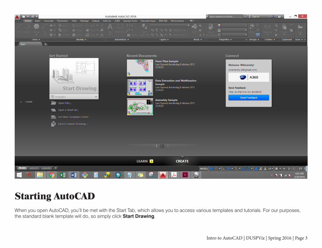
Starting AutoCADWhen you open AutoCAD, you’ll be met with the Start Tab, which allows you to access various templates and tutorials. For our purposes, the standard blank template will do, so simply click Start Drawing.

Intro to AutoCAD | DUSPViz | Spring 2016 | Page 4
Starting AutoCAD (cont.)Now we have a blank file called Drawing1. Notice that we can still see our Start Tab next to Drawing 1. We can create a new tab (and therefore a new drawing) by clicking the “+” button next to the Drawing1 tab. Next, we’ll save our new drawing.

Intro to AutoCAD | DUSPViz | Spring 2016 | Page 5
Saving a FileLet’s save our drawing and give it a better name. Click on the AutoCAD Icon Button in the top left to open the main menu. Click Save and navigate through the file structure to your preferred location. Let’s call our file “My Drawing.dwg” (.dwg is the standard AutoCAD drawing filetype). Note, you can select different filetypes from the dropdown menu in the save window, including older versions of AutoCAD drawings.

Intro to AutoCAD | DUSPViz | Spring 2016 | Page 6
The WorkspaceNow let’s look at the workspace - there’s a lot going on here! The Basic Menu lets you open new files, save, and print. The Ribbon, which is a newer menu type for AutoCAD, contains buttons for drawing, modifying, annotating, and managing your work. the Drawing Selection Tabs let you cycle through open drawings. The View Selection Tabs switch between Model Space and Layout/Paper Space (we’ll go over this later). The Command Prompt lets you type in text commands. The Settings Panel adjusts global settings for our drawings.
Basic Menu
Ribbon
Drawing Selection Tabs
View Selection
TabsCommand Prompt
Settings Panel

Intro to AutoCAD | DUSPViz | Spring 2016 | Page 7
Adjusting the WorkspaceThere are many ways to customize the workspace. For those familiar with older versions of AutoCAD, the Ribbon toolbar can be a bit jarring. Rather than reconfiguring the workspace to revert to older toolbar styles, we’ll simply be using the command prompt (rather than clicking tool buttons) for our entry (this is also usually faster). Let’s add the properties panel by simply typing “properties.” Once the panel opens, click and drag it to the right side of the screen to dock it.

Intro to AutoCAD | DUSPViz | Spring 2016 | Page 8
Adjusting the Settings - SnappingWhen you’re drafting, you often want your elements to snap to existing linework for precision. You can choose what kinds of points CAD will snap by opening the Object Snap Settings. Type “osnap” into the command prompt. In the window that opens, make sure “Object Snap On” and “Object Snap Tracking On” are checked. For our purposes, let’s also make sure “Endpoint,” “Midpoint,” “Center,” “Node,” “Intersection,” “Extension,” and “Perpendicular” are checked. Click OK.

Intro to AutoCAD | DUSPViz | Spring 2016 | Page 9
Working with LayersJust like many other graphics programs, AutoCAD uses layers to manage work (though drawing order is independent from layer order). Let’s make a new layer. Type “la” into the command prompt to bring up the layer management panel. Then type “Alt-n” to create a new layer. Let’s name it “xref.” We’ll leave everything else, but note that this is where you can turn layers on/off, freeze/thaw layers (similar to on/off), lock them from being edited, and change properties like color, linetype, and lineweight. Close the layer manager.

Intro to AutoCAD | DUSPViz | Spring 2016 | Page 10
Working with External ReferencesExternal references (or “xrefs”) allow you to insert linked copies of other drawings or images into your file. Let’s add an xref by typing “attach.” Navigate to the tutorial folder, select “External Reference.dwg,” and click Open. In the Exernal References Window, uncheck “Specify On Screen” under Insertion Point. Click OK. Select the linework and move the xref to the “xref” layer using the Layer drop-down menu in the Layers partition of the Home tab on the Ribbon.
Intro to AutoCAD | DUSPViz | Spring 2016 | Page 11
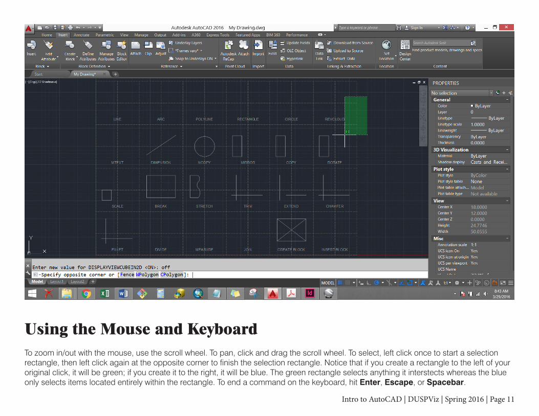
Using the Mouse and KeyboardTo zoom in/out with the mouse, use the scroll wheel. To pan, click and drag the scroll wheel. To select, left click once to start a selection rectangle, then left click again at the opposite corner to finish the selection rectangle. Notice that if you create a rectangle to the left of your original click, it will be green; if you create it to the right, it will be blue. The green rectangle selects anything it interstects whereas the blue only selects items located entirely within the rectangle. To end a command on the keyboard, hit Enter, Escape, or Spacebar.

Intro to AutoCAD | DUSPViz | Spring 2016 | Page 12
Freezing LayersOften, you’ll want to change whether you can see a layer or not. While we can do this from the Layer Manager window, we can also do it right from the workspace. Freezing a layer (as opposed to turning it off) temporarily removes it from AutoCAD’s memory, not just the screen (which is preferred for several reasons). Let’s freeze our dashed construction lines from our xref. Type in “layfrz” and use the curser to click one of the dashed lines. Then hit Enter or Escape.

Intro to AutoCAD | DUSPViz | Spring 2016 | Page 13
Drawing a LineLet’s zoom into the part of our xref that says LINE. To draw a line, type “line” (or “l”). Click once to start the line, release, then click again to end it. AutoCAD will assume you want to continue drawing lines and will start another (unconnected) line at the end of our previous one. To exit the command, hit Enter, Escape, or Spacebar. We can also be more specfic when we draw our lines by entering the length of the line after the first click (try starting a line, and typing in “4” - then hit Enter). We can also specifiy the angle and absoluet start/end coordinates.

Intro to AutoCAD | DUSPViz | Spring 2016 | Page 14
Drawing an ArcPan over to the ARC section. To draw an arc, type “arc” (or “a”). Click once for the start point, click again for the second point, and click one last time to end the arc. As is the case with most AutoCAD commands, the command prompt will offer different options as we draw. After our first click, the prompt says “Specify second point of arc or [Center End]”. By typing in “center” or “end” (or their underlined letters), we can change how we want to define our arc as we’re drawing it.

Intro to AutoCAD | DUSPViz | Spring 2016 | Page 15
Drawing a PolylineUnlike a line, the segments of a polyline are connected to make one complete object. Polylines can also have arced segments. To start, type “polyline” (or “pl”). Each click of the mouse will add a new segment point. If we want to add an arced segment, type “a” and then hit Enter. Unlike in the Arc command, we only need to click the start and end of each arc segment - the arcs will automatically be tangent to the previous segment. To switch back to line segements, type “l” and hit Enter.

Intro to AutoCAD | DUSPViz | Spring 2016 | Page 16
Editing GripsMany AutoCAD objects use “grips” to allow for manipulation. Let’s stay with our Polyline, and see what the grips do. Click any corner grip to activate it. Click again to move that point to a new location, altering the shape of our line. Adjusting the midpoint grip of a line segment moves that segment as-is and adjusts its neighbors. The midpoint grip of an arc segment changes the radius. After selecting a grip, you can hit Control several times to cycle through other options like removing a vertex or converting lines to arcs and vice versa.

Intro to AutoCAD | DUSPViz | Spring 2016 | Page 17
Drawing a RectangleType “rectangle” (or “rec”) to begin. Click to start our first point. We could click again to set our opposite corner and complete our rectangle, but instead, let’s type “d” for dimensions after our first click. Now type in the length (horizontal) we want (let’s say 3), hit Enter, and do the same for the width (vertical).

Intro to AutoCAD | DUSPViz | Spring 2016 | Page 18
Drawing a CircleType “circle” (or “c”) to begin. Click to start in the center of the circle. As you move the mouse away from that center, type in “1.5” to specify the radius; hit Enter. As you can see from the command prompt, there are also other ways to draw a circle - 3-point, 2-point, and Tangent-Tangent-Radius.

Intro to AutoCAD | DUSPViz | Spring 2016 | Page 19
HatchingHatching allows us to fill shapes with patterns, including solid colors. To begin, draw a rectangle (“rec”). Then type in “hatch” (“h”). By default, the tool lets us click any point within a shape to fill it. We can also type “s” to switch to the “Select objects” option which allows us to select multiple boundary objects. Click to accept the hatch location.

Intro to AutoCAD | DUSPViz | Spring 2016 | Page 20
Hatching - Adjusting the HatchNow select the hatch by clicking on it. We can use the Properties Panel to change the look of our hatch including the pattern type, pattern size, color, rotation, and more. The default hatch is ANSI31, which is a series of lines at a 45-degree angle. Let’s change our pattern to ANSI37 in the “Pattern name” drop-down menu. Next, enter “45” in the “Rotation” section to turn our hatch, and enter “3” in the “Scale” section to increase the size of our hatch. Once you’re finished, press “Escape.”

Intro to AutoCAD | DUSPViz | Spring 2016 | Page 21
Typing TextThere are two ways to enter text in AutoCAD: “text” is an older method that takes on some strange properties when you try to edit it. Multi-line text (or “mtext”) will seem much more familiar if you’ve ever typed into a text box. We’ll be using mtext. To begin, type “mtext”, select our first corner, and select our opposite corner. You’ll see that the Ribbon changes to bring up text modifications like font, color, and size (in inches, not points!). After you’ve modified the text as you see fit, you can exit the text box by clicking outside of it or hitting Escape.

Intro to AutoCAD | DUSPViz | Spring 2016 | Page 22
DimensionsWe often need to illustrate measurements on our drawings. To dimension the line from our xref, type “dimension” (or “dim”). Then click one end of the line to set the first point, and click the other end of the line to set the second. As we move the mouse away from the line, our dimension gets further from it. Note that the dimension orientation will change based on how you move the mouse. Let’s make sure the dimension is parallel to the line and hit Enter. You can change the dimension’s properties (e.g. text size, arrow type) in the Properties Panel.

Intro to AutoCAD | DUSPViz | Spring 2016 | Page 23
Copy Nested ObjectsYou’ve probably noticed that while you can select the xref, you can’t edit any of the linework in it. To copy nested linework (that is, linework from an xref or a block), we can use “ncopy”. Type in “ncopy” then select the circle from the xref. Hit Enter - the command prompt will ask us for a base point. Hit Enter again to skip this. Next, it will ask us for a displacement from the origin (since we didn’t select a base point). Hit Enter again to skip this and match the current location of the object. Hitting Escape after selecting the object will skip these steps.

Intro to AutoCAD | DUSPViz | Spring 2016 | Page 24
MirrorStart by Ncopying the shape from our xref. Then type “mirror” (or “mi”). Select our Ncopied rectangle and hit Enter. Click two points to draw the line around which our object will be mirrored (note: the line can be at any angle). After clicking the second point, the command prompt will ask whether we want to erase source objects (the default is No). Hit Enter to accept the default and keep the original shape in addition to our mirrored copy.

Intro to AutoCAD | DUSPViz | Spring 2016 | Page 25
CopyAgain, using Ncopy, bring in the shape from the xref. Type in “copy” (or “co”), select the object, and hit Enter. Then, select a base point (let’s use the bottom left corner of the rectangle). Any subsequent mouse clicks will place a copy of the object using this base point. You can click to create as many copies as needed. To exit the command, hit Enter.

Intro to AutoCAD | DUSPViz | Spring 2016 | Page 26
RotateNcopy the shape below. Type in “rotate” (or “ro”), select the object, and hit Enter. Click to select the base point around which we’ll rotate (let’s use the midpoint of the right edge. As we move the mouse, the object will freely rotate (though it will snap to 90-degree angles. The further our mouse is from the base point, the more rotation precision we will have. A second click will set the rotation. If we want to keep our Ncopied original in addition to our rotated shape, we can type “c” (for “copy”) prior to our final click.
Intro to AutoCAD | DUSPViz | Spring 2016 | Page 27
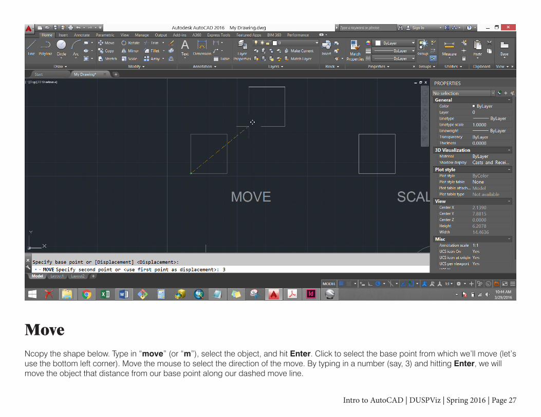
MoveNcopy the shape below. Type in “move” (or “m”), select the object, and hit Enter. Click to select the base point from which we’ll move (let’s use the bottom left corner). Move the mouse to select the direction of the move. By typing in a number (say, 3) and hitting Enter, we will move the object that distance from our base point along our dashed move line.

Intro to AutoCAD | DUSPViz | Spring 2016 | Page 28
ScaleNcopy the shape below. Type in “scale” (or “sc”), select the object, and hit Enter. Click to select the base point from which we’ll scale (let’s use the bottom left corner). Move the mouse to select the direction of the scale. By typing in a number (say, 2.5) and hitting Enter, we will scale the object by that factor from our base point along our dashed scale line. Similar to rotate, we can type “c” prior to typing in our scale factor to keep an unscaled copy of the original.

Intro to AutoCAD | DUSPViz | Spring 2016 | Page 29
BreakNcopy the shape below. Type in “break” (or “br”). Click once to select the first break point, then click again further down the shape to select the second. You can also select the same point if you simply want to split the shape without removing any of it.

Intro to AutoCAD | DUSPViz | Spring 2016 | Page 30
TrimNcopy both of the lines. Type in “trim” (or “tr”). Select the trim object first (this is the edge that will “cut” the other line) - let’s select the horizontal line. Then hit Enter. Next select the line to be trimmed. Be sure to select the portion that will be removed. Hit Enter. Note, in both steps, you can select multiple lines. That is, you may want to trim a line at multiple points using multiple trim lines, or you may want to use a single trim line to snip multiple lines (or both).

Intro to AutoCAD | DUSPViz | Spring 2016 | Page 31
ExtendThis is Trim’s cousin. Ncopy both of the lines. Type in “extend” (or “ex”). Select the boundary object first (this is the edge to which the other line will extend) - let’s select the vertical line. Then hit Enter. Next select the line to be extended. Hit Enter. Again, in both steps, you can select multiple lines. If you select multiple boundary lines (say you want to extend a line at both ends), be sure to click the half of the line (past the midpoint) you wish to extend that is closest to the appropriate boundary line.

Intro to AutoCAD | DUSPViz | Spring 2016 | Page 32
ChamferChamfer connects two lines with an angle. Ncopy both of the lines. Type in “chamfer” (or “cha”). Type “d” for distance to set the distance from the corner to start the chamfer (let’s use “1”). Hit Enter. Hit Enter again to keep the same distance for the second line (we could also specify the angle or other settings). Select both lines (you’ll probably need to do this one at a time). Also, be sure to select the portions of the lines you want to keep. Hit Enter to finish.

Intro to AutoCAD | DUSPViz | Spring 2016 | Page 33
FilletSimiliar to chamfer, fillet connects two lines with a radius. Ncopy both of the lines. Type in “fillet” (or “f”). Type “r” for radius to set the radius for our connecting arc (let’s use “1”). Hit Enter. Select both lines (you’ll probably need to do this one at a time). Also, be sure to select the portions of the lines you want to keep. Hit Enter to finish.

Intro to AutoCAD | DUSPViz | Spring 2016 | Page 34
DivideDivide splits an object into segments of equal lenght; however, it doesn’t physically break the object. Instead, it simply places point objects at the split points. Start by changing your point type to something visible. Type “ptype” and select the circle with the cross in it. Click OK. Next, type “divide” (or “div”). Select the Ncopied curved line. Type in the number of segments (let’s use 5) and hit Enter.

Intro to AutoCAD | DUSPViz | Spring 2016 | Page 35
MeasureMeasure is similar to divide, but instead of equal parts, it places points along an object at a specified distance. Type in “measure” (or “me”) and select the Ncopied object (Note: it matters which end of the object you select - this will be the beginning of the measurement. If your object is not evenly divisible by the length you select, the opposite end may have a shorter segment.) Type in a length (let’s use 1), and hit Enter. For Measure and Divide, you could choose to insert blocks along the shape instead of points if you want.

Intro to AutoCAD | DUSPViz | Spring 2016 | Page 36
Join/ExplodeOften, you’ll want unconnected objects to be connected and vice versa. To Join these two Ncopied lines, type “join” (or “j”) and select the lines. Then hit Enter. To explode our newly connected lines (which are now a single polyline), type “explode,” click on the line, and hit Enter. Explode is also handy for breaking up blocks. Additionally, as objects become more or less complex, they change properties. For example, an exploded polyline becomes two lines, not two polylines.

Intro to AutoCAD | DUSPViz | Spring 2016 | Page 37
Create a BlockBlocks are grouped CAD objects that can have unique properties, be called on in our file, and be inserted into other files. Let’s create a block using the rectangle and two polylines here. First, Ncopy them into our drawing. Then select all three components (use the blue selection to ignore the xref below). Then type “block” (or “b”) to open the Block Definition window. Name the block “X Box” and make sure “Specify on Screen” is checked under Base Point. Click OK, and select the block’s base point on screen (let’s use the center of the X).

Intro to AutoCAD | DUSPViz | Spring 2016 | Page 38
Insert a BlockWe can also insert blocks from other files, or insert entire files as a block. Let’s insert the Tree.dwg file as a block. Type “insert” (or “i”) to bring up the Insert window. Click the Browse button to navigate through the file system and select Tree.dwg. Make sure “Specify on Screen” is checked under Insertion Point and unchecked under Scale. Ensure the rest of your window matches the one above and click OK. The Tree.dwg file was drawn with the origin at the center of the tree, so wherever we click, we’ll insert the tree at its center.

Intro to AutoCAD | DUSPViz | Spring 2016 | Page 39
Layout/Paper SpaceWhen we’re ready to print, we should move to Layout/Paper space. Similar to ArcMap, AutoCAD uses two different frameworks for drawing and printing. Model space is where we do all of our drafting at full scale. Layout/Paper space allows us to scale down our drawings for printing. Click the Layout1 tab in the bottom left of the screen to move to Layout space.

Intro to AutoCAD | DUSPViz | Spring 2016 | Page 40
Layout/Paper Space - Adjusting the LayoutRight-click on the “Layout1” tab and select “Page setup manager...”

Intro to AutoCAD | DUSPViz | Spring 2016 | Page 41
Layout/Paper Space - Adjusting the LayoutMake sure “Layout1” is highlighted, and click “Modify.”

Intro to AutoCAD | DUSPViz | Spring 2016 | Page 42
Layout/Paper Space - Adjusting the LayoutFrom the Page Setup window, we can select our default printer for this layout, adjust the size of our page, and select several other plotting options. For now, let’s use “AdobePDF” as our printer, and set our “Page size” to “Arch D” (which is 24”x36”). Make sure our “Plotting area” is set to “Layout,” our “Plot offset” is set to “0,” and our “Drawing orientation” is set to “Landscape.” Click “OK“ to save our changes. then click “Close” on the Page Setup Manager window.

Intro to AutoCAD | DUSPViz | Spring 2016 | Page 43
Layout/Paper Space - Adjusting the LayoutOur page size has changed, but the viewport that allows us to see our Model space hasn’t. Let’s select the bounding box of our viewport. Then click the upper-right grip and move it to the upper right corner of our page to expand the size of our viewport.

Intro to AutoCAD | DUSPViz | Spring 2016 | Page 44
Layout/Paper Space - Adjusting the LayoutWe can continue to work in Layout Space view, but actually complete tasks in Model Space. Double-click inside the viewport to enter Model Space. Then type “z” (zoom) and “e” (extents) to zoom our viewport and center on our work. However, this is not set to a particular scale. Double-click outside the viewport to leave Model Space, then select the bounding box of the viewport. Open the scale flyout menu in the bottom right, and select 1:1. Now click the “lock” symbol next to the scale flyout to prevent further changes.

Intro to AutoCAD | DUSPViz | Spring 2016 | Page 45
Plot to PDFType Ctrl+P to bring up the Plot window. Because we adjusted all of our settings in the Page Setup Manager, we can just press OK. Great - we’ve created our first drawing!
Intro to AutoCAD | DUSPViz | Spring 2016 | Page 46
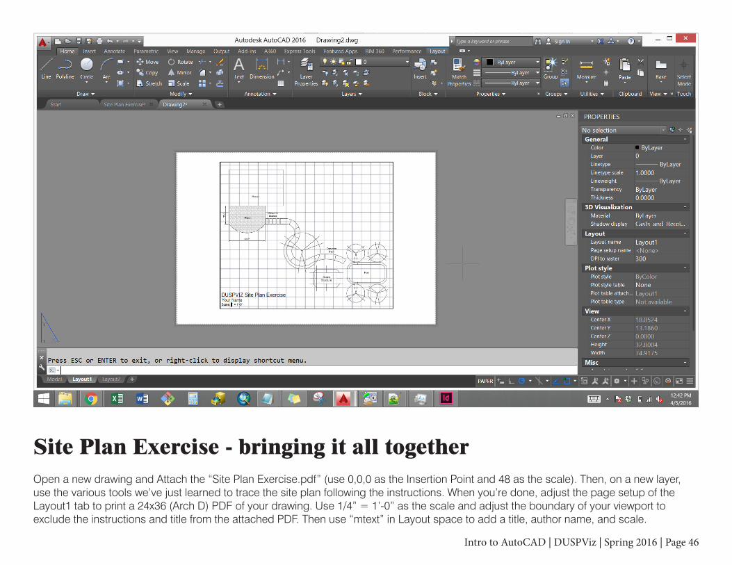
Site Plan Exercise - bringing it all togetherOpen a new drawing and Attach the “Site Plan Exercise.pdf” (use 0,0,0 as the Insertion Point and 48 as the scale). Then, on a new layer, use the various tools we’ve just learned to trace the site plan following the instructions. When you’re done, adjust the page setup of the Layout1 tab to print a 24x36 (Arch D) PDF of your drawing. Use 1/4” = 1’-0” as the scale and adjust the boundary of your viewport to exclude the instructions and title from the attached PDF. Then use “mtext” in Layout space to add a title, author name, and scale.


![INTRO TO AUTOCAD contact details ABOUT€¦ · contact details L e a r n basic 3D concepts & create surfaces. INTRO TO AUTOCAD P R I C E : R8900/£500 [Courseware Inclusive] C O U](https://static.fdocuments.in/doc/165x107/5f02a9977e708231d40562b5/intro-to-autocad-contact-details-about-contact-details-l-e-a-r-n-basic-3d-concepts.jpg)