Intraocular Lens Materials & Manufacturing Technology …benzrd.com/Uploads/2013_benz_manual.pdf ·...
22
Intraocular Lens Materials & Manufacturing Technology 2013
Transcript of Intraocular Lens Materials & Manufacturing Technology …benzrd.com/Uploads/2013_benz_manual.pdf ·...

IntraocularLens Materials
& ManufacturingTechnology
2013

THE NEXT GENERATION HYDROPHOBIC MATERIAL HF-2
Preloaded MICS
HF-2 is the newest material from Benz, and has been designed as part of a two hydrophobic
material strategy. HF-2 is designed for MICS injectors and fast opening times of under 10
seconds. HF-1.2 is designed for 2.2 – 2.4 mm injectors and has an opening time of 25 seconds
(HF-1.2 is discussed in detail on pages 10 – 11). Both materials are available in the Universal
Blank format that greatly reduces the cost of manufacturing hydrophobic IOLs.
HF-2 is intended for high value markets that require preloaded MICS capable designs and fast
opening times. Lenses made from HF-2 are dry sterilized in plasma or ethylene oxide and do
not require wet packaging to achieve both non-stickiness and very low glistenings that are
well below the clinical threshold. HF-2 is a unique hydrophobic acrylic polymer that achieves
these very advantageous characteristics while maintaining an Abbey number of 47, becoming
the fi rst MICS capable hydrophobic material with low chromatic aberration.
HF-2 Natural Yellow IOLs have the same Abbey number (47) AND the same transmission
spectrum as the young Human Crystalline Lens. The spectral characteristics of HF-2 Natural
Yellow IOLs provide the cataract patient with visual characteristics that are the closest yet
to the young Human Crystalline Lens.
Cryo Blocking
HF-2 Universal Blanks can be Cryo Blocked by hand using a Benz Table Top freezing device and cryo mandrel or Blocked Optically using the Benz Optical Cryo Blocker. Hand blocking achieves a concentric accuracy of approximately 40 microns. Optical Blocking achieves a concentric accuracy of <10 microns. Benz Blocking Water mixture is used for blocking in both methods.
Cryo Milling
HF-2 can be cryo milled using either the Benz Peltier Cryo Mill or a MLC (mill/lathe combo), DAC or Optoform, fi tted with a Benz Vortex cooling device. The use of an MLC is a one stop process of machining and milling. Using a separate Cryo Mill requires cleaning the Universal Blank after machining and re-freezing it on the Peltier plate of the mill. The milling parameters are the same as HF-1.2, p. 15.
Cryo Machining
Machining the Cryo Blocked HF-2 Universal blank is a two pass process carried out at a -28°C surface temperature with -31°C blow off air. The machining parameters are the same as HF-1.2, P 15.
Sterilization
HF-2 lenses can be Ethylene Oxide sterilized as is typical for dry sterilized hydrophobic IOLs. Recently, Benz has successfully sterilized both HF-1.2 and HF-2 by H2O2 Plasma. This new method is safe, effi cient and has a convenient with cycle time of approximately 50 minutes.
Water Content; Wt% < 5% < 5%
UV Cut Off (1mm disc) < 2% @ 400nm < 10% @ 370nm
Residuals; % < 0.15% < 0.15%
Optic Purity >99.98% >99.98%
Severity Index < 750 < 750
Refractive Index at 589nm At 20˚C 1.519 At 20˚C 1.519 (Nominal Value) At 35˚C 1.514 At 35˚C 1.514
Refractive Index at 546nm At 20˚C 1.520 At 20˚C 1.520 (Nominal Value) At 35˚C 1.515 At 35˚C 1.515
ABBE Number 47 47
Tg 10˚C 10˚C
Opening Time @ 25˚C* 10 sec 10 sec
*Opening Times based on a +27 D C-Loop with a 6.0 mm optic using a 2.2 mm Medicel Accuject Injector
Dimension Specifications for HF-2 Universal blanks are on page 10.
Benz HF-2 Natural Yellow™
HF-2 SPECIFIFATIONS
Benz HF-2 UVX™

Introduction to Benz IOL Materials & Manufacturing TechnologyBy Dr. Patrick H. Benz, president
Since entering the IOL materials market in 1998, Benz Research and Development has become the
preeminent supplier of quality high performance materials and state of the art technology to the IOL
industry. The reason for our strong growth is our dedication to excellence in both Quality and Innovation.
Our 26 years experience in producing high quality materials for the soft contact lens industry also provides
a very signifi cant foundation for hydrophilic IOL materials.
Expertise in high purity 2-HEMA monomer production extends over 27 years of continuous development.
Our hydrophilic polymer experience of 22 years is substantial. In conjunction with producing 15 novel
polymer materials, we have 19 US patents and 14 foreign patents. Combining this level of expertise in
developing new materials, it is apparent why we have quickly become the leader in IOL materials and we
continue our innovation with 9 US patents pending and
16 foreign patents pending.
Our current product line consists of three hydrophilic
IOL materials (IOL25 Universal Blank, IOL25, BenzFlex
26) and two hydrophobic IOL materials (HF-1.2 Universal
Blank and HF-2 Universal Blank). All of these materials
are available with our patented, covalently bound, natural
chromophore, Natural Yellow.™ In creating patented, value
added materials, we provide our customers opportunities
for signifi cant market differentiation, including increased
value to the surgeon as well as the patient.
Since 1995 Benz Research and Development has committed many man-years of effort to advance
the state-of-the art in lens manufacturing technology. Our efforts have yielded both innovative and
powerful manufacturing technologies for today’s IOL manufacturer. These advances include Optical
Blocking, Laser Blocking, Automated Video Inspection, Optical Cryo Blocking, Automated Laser Profi ling
of Aspheric Optics, a fully Integrated Hydrophilic IOL Manufacturing System and our newest Automated
Cryo Manufacturing, all validated to the ISO 13485 standard. Our newest material products are the
HF-1.2 Universal Blank, HF-2 Universal Blank and the IOL25 Universal Blank. These unique products
greatly reduce the manufacturing costs while increasing the precision of IOL manufacture. With our
commitment to R&D, we continue to expand the boundaries of both IOL materials and manufacturing
technology. Developing superior technology to make superior products — this is what Benz Research
and Development is all about.
IOL Manufacturing Technologies Developed by Benz
Micron run-out Spindle Collets
Optical Blocking
Optical Cryo Blocking
Peltier Effect Cryo Milling
Automated IOL Micro Drill
Integrated Lens Manufacturing (ILM-3), full automation
Fully automated IOL25 Universal Blank Manufacturing (UBM)
Fully automated Cryo Manufacturing (ILM-C)

Most manufacturers would agree that high quality products
start with high quality raw materials. To the IOL manufacturer,
this means the highest quality polymer blanks. For Benz
Research and Development this means starting with the
very highest Quality monomer raw material possible,
period and controlling that quality. Fortunately, we have a
vast amount of expertise in the manufacture of high purity
2-Hydroxyethylmethacrylate (2-HEMA), the primary monomer
component used in hydrophilic acrylic IOL material. In the
mid-1980s we developed a 2-HEMA manufacturing process that
produced 99.5% pure monomer, a bench mark for the soft lens
industry world wide for more than 19 years. Therefore, we have
core expertise in a technology vital to Quality IOL materials.
Six years ago, one of our goals as a company was to develop
an advanced 2-HEMA manufacturing process that produces
raw material monomer with a purity that is consistent with
the requirements of the IOL industry rather than the soft
lens industry. We call this process Zero Technology. Our Zero
Technology Process delivers an ultra pure material with
99.9% purity, the quality expected for a polymer implant that
may be in the eye for more than 40 years. We call our IOL
monomer, L3 Monomer, for Log 3 or 99.9.
This technology advancement makes Benz R&D the only IOL
material supplier that has actual control of its raw material
quality and separates us from our competitors, who continue
to use raw materials manufactured to meet molded soft lens
requirements, not IOL material requirements. We are the only
IOL material supplier that is basic in its 2-HEMA monomer
raw material.
Zero Technology produces a raw material that is so pure that
the methacrylic acid content is diffi cult to even measure.
The resulting hydrophilic acrylic IOL polymer has 10 to 20X
less acid than even “highest purity” commercial monomer,
plus a much higher total purity, this results in a zero ionicity
polymer. Zero ionicity IOL material provides a further degree
of Quality Assurance by eliminating the possibility of calcium
phosphate particles appearing over time in the polymer
matrix, which can lead to opacifi cation, see Figure 1.
Z E R O T E C H N O LO GY &
U LT R A P U R E M O N O M E R
2 3
monomer99.9%
Figure 1
Calcium Particle Formation
Calcium Phosphate ParticleCalcium Phosphate
Methacrylic Acid In The Polymer Matrix
Polymer Matrix Polymer Matrix
COO- + Ca+2 HPO4-2 +H3O+ COO- Ca+2 H2PO4
- + H2O

The reputation of Benz Research and Development as a
manufacturer of very high quality contact lens materials is
well known in the custom contact lens industry. In fact, we
would probably be considered the quality benchmark even
by our competitors. Benz materials are characterized by low
residuals, precise and isotropic expansion, and large batch sizes.
Benz R&D currently makes the highest purity, most consistent
hydrophilic and hydrophobic IOL materials, period. An actual
comparison of the quality resulting from Benz polymerization
technology vs. our competitors polymerization technology
is straightforward. Our BenzFlex 26 consistently has a much
lower residual monomer content (0.5% vs. 1.1%) and a smaller
matrix or pore size (33% smaller) than competitor materials
made from the same monomers (see Figures 2 and 3). Another
example of quality is shown by examining how completely the
UV blocker is covalently bound to the polymer. A substantial
difference between BenzFlex 26 and competitor material
can be seen in Figures 4 and 5. There are several important
reasons for our high quality.
First, our quality starts with ultra high purity raw materials.
The purity of our raw materials is much higher than that
provided as “high purity” by the chemical companies that
currently manufacture 2-HEMA. Our ultra pure, L3 Monomer
signifi cantly reduces batch-to-batch variability and lowers
the residual monomer content of
our hydrophilic IOL materials.
Second, our polymerization process is carried out in virgin
glass tubes, not the plastic molds of competitor materials.
Plastic molds contain many impurities that affect the
polymerization process as well as contaminate the resulting
polymer, sometimes with toxic components not intended for
IOL use. To understand the scope of the contamination from
B E N E F I T S O F
B E N Z P O LY M E R I Z AT I O N
T E C H N O LO GY
4
Figure 2
1.2
1.0
0.8
0.6
0.4
0.2
Residuals Comparison
CompetitorBenzFlex 26
Residuals
Perc
ent R
esid
uals
(%)
plastic molds, you need only to look up all the types of
plasticizers, mold release agents, lubricants and antioxidants
commonly found in polypropylene and polyethylene resins.
These same chemical contaminants can be found in competitor
materials. Virgin glass molds eliminate contamination. Benz
has made it a company priority to use virgin glass molds that
cost substantially more, but provide the assurance of polymer
purity that is essential to Benz Quality.
Third, our polymerization process is carried out in a
uniquely designed computer controlled chamber capable of
polymerization with extreme temperature stability. This
polymerization environment, when combined with advanced
formulation technology, ultra pure monomer and inert glass
molds, allows us to make an extremely consistent, isotropic
polymer. The characteristics of the resulting polymer speaks
for itself. The data support our claims that we have the most
complete polymerization under the most controlled conditions,
period. Making Quality claims based on actual data is
consistent with our marketing approach which is one based
on verifi able product characteristics. Hopefully, this approach
will also become an industry standard.
Fourth, since our polymerization process was designed and
developed by Benz, not adapted from another company’s
production process (such as old contact lens blank casting
processes), our polymerization technology is easily scalable
and not labor intensive. This advantage means that we
produce IOL blanks in batch sizes that are appropriate for
our customer’s requirements. Other manufacturers produce
batch sizes that are limited. Our current batch sizes range from
40,000 to 80,000 blanks per batch. Large batches increase
the reliability of supply as well as provide for more effi cient
manufacturing because of less batch qualifi cation tests.
5
Figure 3
1.8
1.6
1.4
1.2
1
0.8
0.6
0.4
0.2
Matrix Size Comparison
CompetitorBenzFlex 26
Rela
tive
Diff
usio
n Ra
te
Figure 4
Competition
Unbound UV-Blocker residual from alcohol extraction of a hydrophilicIOL material (26% water) from Competitor material.
Figure 5
BenzFlex 26UV
No UV-Blocker residual from alcohol extraction of a hydrophilicIOL material (26% water) from BenzFlex 26.

23.878Edge Height
Provided In Data Table
6 UM Or BetterLens Concentricity To Mandrel Shank
0.23 Clearance
Ø 12.700±0.010
23.65 A
A
Section C-C
3°
0.006 0.006
0.006
0.005
B
B
THE PRECISION
GROUND BLANK &
IOL 25 UNIVERSAL BLANK
6 7
IOL blanks with consistent and precise dimensions directly
benefi t your manufacturing process. Benz Research and
Development uses unique high-speed processes for converting
our high purity polymer into a precision dimensioned blank,
Figure 6. We grind blanks automatically to micron tolerances in
diameter and thickness, with optimum squareness and parallel,
using state of the art machinery and statistical process control
to ensure a highly uniform batch. We invested heavily in this
high volume equipment and technology so that we could
process large batches with precision dimensions. Figures 7 and
8 show typical results for diameter and thickness (in microns)
of a batch of Benz IOL 25UV, 0512072I25. A large batch of I-25
Natural Yellow™ is shown in Figure 9.
Precision dimensions facilitate auto-loading processes and
eliminate the need to electronically locate the surface of the
blank before each machining cycle begins on the lathe. This
alone eliminates about 5 seconds from every lathe cycle saving
signifi cant time and money.
Figure 9 Figure 10
Figure 9
The new IOL 25 Universal Blank is a precision molded disk,
100% inspected for visual and optical defects and laser
mounted on a precision polycarbonate mandrel, see Figure 10.
Figure 6
Diameter, Thickness, Parallel and Squareness
3.0 0.010 mm+–
12.7 0.010 mm or 14.5 0.010 mm or 16.0 0.010 mm
0.003 mm 0.008 mm MAX
+–
+–
+–
Figure 7
Diameter Distribution for Benz IOL 25UV LOT 05-12-072125
12.68612.689 12.694 12.699 12.704 12.709 12.714
USLLSL
24
18
12
6
+3.0s-3.0s
Tag
12.692 12.697 12.702 12.707 12.712 12.717
Microns(lot size 63,000 blanks)
Freq
uenc
y
Figure 8
Thickness Distribution for Benz IOL 25UV LOT 05-12-072125
2.9872.990 2.994 2.998 3.003 3.007 3.011
USLLSL
36
27
18
9
+3.0s-3.0s
Tag
2.992 2.996 3.000 3.005 3.009 3.014
Freq
uenc
y
Microns(lot size 63,000 blanks)

Benz Research and Development has been manufacturing
hydrophilic acrylic IOL materials for many years. During this
time, literally tens of millions of IOLs made from Benz materials
have been implanted. Our material’s reputation in the industry
is one of high quality and consistent trouble-free service. The
development of Zero Technology will assure our customers
that Benz will provide the highest purity polymer available for
their implant products for years to come. Benz materials are
made in virgin glass molds free of potential contamination from
plasticizers, mold release agents, lubricants and anti-oxidants.
Benz IOL 25
IOL 25 is our patented hydrophilic material (US Patent No. 6,517,750),
especially effective for small bore injectable IOLs. This copolymer
of 2-Hydroxyethylmethacrylate and 2-Ethoxyethylmethacrylate
has a unique combination of modulus of elasticity and tensile
strength that allow the fi nished IOL to be drastically deformed
during injection through openings as smaller than 1.6mm and
return to its original shape and optical performance in the most
desirable time frame. This material also has a history of very low
PCO rates across many designs. The physical properties of Benz
IOL 25 are shown in Table 1.
Benz IOL25 Universal Blank
The Universal Blank is the same material molded as a disk and
precision blocked on a disposable precision mandrel. The posterior
aspheric optic is complete with a 70 micron square edge (hydrated).
A fi nished lens ready to polish or a polish free lens ready to hydrate
require the same manufacturing steps: one rough cut, one fi ne cut
and one milling pass. Polish ready or polish free is determined by
the equipment used for the machining step. Deblocking the lens is
done mechanically, with only the lens removed. The total cost for
a fi nished IOL25 hydrophilic lens prior to inspection and packaging
using this method is <US $4.00 (see Global Contact, issue 2, 2013,
article New Methods in Hydrophilic IOL Manufacturing).
BenzFlex 26
BenzFlex 26 is a generic material made from
2-Hydroxyethylmethacrylate and Methylmethacrylate.
This material’s primary components are the same as other
products available on the market and has similar mechanical
properties. The main differences are that BenzFlex 26UV is
made with Benz Zero Technology ultra pure monomer and our
superior polymerization technology as well as made in virgin
glass molds. There are important quantitative differences
resulting from Benz Zero Technology monomer, Benz’s superior
Polymerization Technology and virgin glass molds. These
advantages are: very low residuals, zero ionicity, a smaller
matrix (pore size), more precise expansion characteristics
than competitor materials and no contamination from
impurities found in plastic molds. The physical properties of
BenzFlex 26 UV are shown in Table 1.
Nature’s Own Light Filter
Benz IOL 25 Natural Yellow™ and BenzFlex 26 Natural Yellow™
are the fi rst IOL materials to incorporate the same UV-A blocking
and violet light fi ltering chromophore that is in the human
crystalline lens. Our approach to UV blockers and violet fi lters
is to use nature’s own solutions to the problem of protecting the
retina from harmful energetic light. The absorption spectrum
of the chromophore, 2-Hydroxykynureneine (Figure 11) shows
that this natural chromophore is an excellent UV-A blocker
with a secondary purpose of fi ltering (not blocking) violet
light. This and its beta Glucoside derivative are nature’s
primary protection for UV-A and violet light. We have made
a special monomer (U.S. Patent 7,947,796) containing the
identical chromophore present in the human crystalline lens and
covalently incorporated it into our premier IOL materials. We call
these proprietary natural light fi ltering materials “Natural Yellow™”.
The visible transmission spectrum of Benz IOL 25 Natural
Yellow™ material, 1.0 mm thickness is shown in Figure 12
compared to the transmission spectrum of a young human
crystalline lens as defi ned by van de Kraats and van Norren
(OSA, posted February 7, 2007, doc ID 76626).
B E N Z H Y D R O P H I L I C
I O L M AT E R I A L
8 9
Natural Yellow™ is superior to other yellow IOL materials because it protects
the retina without blocking needed blue light. Blue blocking IOLs reduce low light contrast sensitivity
as well as color perception. These capabilities are critically needed for optimum vision of implant
patients, particularly at night. Benz Natural Yellow™ achieves complete natural protection
without loss of contrast sensitivity or color perception. The human retina has already specifi ed the
exact chromophore it needs for energetic light protection through millions of years evolution,
and that is exactly the chromophore we deliver to our customers, in Benz Natural Yellow™.
Table 1
Water Content (wt %) 25 26 25
Refractive Index @ 589 nm
Dry 20°C 1.507 1.509 1.507
Hydrated 20°C 1.460 1.462 1.460
Refractive Index @ 546 nm
Dry 20°C 1.509 1.510 1.509
Hydrated 20°C 1.462 1.464 1.462
Expansion
Linear 1.125 1.125 1.125
Radial 1.125 1.125 1.125
Tensile g/mm2 33 95 31
Young’s Modulus g/mm2 62 92 69
Diameter (mm) 12.7±0.01 12.7±0.01
14.5±0.01 14.5±0.01
16.0±0.01 16±0.01
Thickness (mm) 3.0±0.01 3.0±0.01
Benz IOL BenzFlex IOL 25Property 25 26 Universal Blank
M(LY)
BENZ Natural Yellow™ IOL Materials
340 360 380 400 420 440 460 480 500 520 540 560 580 600 620
Figure 12
Comparison of a Young Lens, M(LY) vs. Benz IOL 25 Natural Yellow™
100
Wavelength (nm)
% T
ran
smis
sio
n
90
80
70
60
50
40
30
20
10
0
Figure 11
5.0
320 340 360 380 400 420 440 460
Wavelength (nm)
Ab
sorb
ance
4.5
4.0
3.5
3.0
2.5
2.5
1.5
1.0
0.5
0.0
Comparison of 3-HydroxyKynurenine in Saline vs. Benz Natural Yellow™ Chromophore
UV-A Blocking
Violet Filtering
“ImprovedScotopic Vision”
3-HydroxyKynurenine in Saline
BENZ Natural Yellow™ Chromophore

While the Benz hydrophilic materials offer the ultimate
in reliability and performance in a highly biocompatible
hydrophilic polymer, our HF-1.2 hydrophobic material offers
customers a signifi cant additional value added market
because of the promotion of hydrophobic materials by the
market leaders.
We have been developing HF-1.2 material for 9 years and as
a result of the latest developments, the opening time has
been reduced from 60 seconds to 25 seconds. Because of this
improvement, HF-1 is now called HF-1.2.
This material has many advantageous characteristics resulting
in a high performance IOL:
• Low chromatic aberration, Abbe number 49
• Very low glistenings (well below clinical threshold)
• Opening time approximately 25 seconds at 25°C
• Mechanical properties similar to IOL 25UV
The Glistening behavior of hydrophobic acrylic rubbers
is well known and has been present ever since the fi rst
products were introduced in the early 1990’s. One of the
most popular hydrophobic IOL materials is the acrylic co-
polymer: 2-Phenylethylacrylate/2-Phenylethylmethacrylate,
the material of the market leading IOL. Recent clinical
reports on the extent of the glistenings of market leading
products and their clinical signifi cance provide marketing
opportunities for new hydrophobic IOL products, such as
Benz HF-1.2.
We have studied extensively the relationship of glistenings
to the manufacturing process parameters in developing the
current process for Benz HF-1.2. We have also adopted the
Trattler Severity Index as a Quality Assurance procedure for
each batch of material. The Severity Index for HF-1.2 batches
has been followed for months submerged in saline
B E N Z H F -1 . 2
H Y D R O P H O B I C
I O L M AT E R I A L
10 11
and does not change from the fi rst 24 hours submerged in
saline. The average Severity Index of 85 batches HF-1.2 is
compared below to the severity index of the market leading
IOL material, see Table 2.
Obviously, there is a clear difference with respect to
glistenings for these two materials. The reasons are not
completely known, but obvious differences in the two
materials are the formula components and likely differences
in the polymerization processes. The superior quality of Benz
HF-1.2 with respect to glistenings is apparent.
Benz HF-1.2 Natural Yellow™ Universal Blank is the same
polymer composition as the original HF-1 with the addition of
the Benz Natural Yellow™ UV-A blocking and Violet Filtering
monomer (US Patent 7,947,796). Benz Natural Yellow™
gives HF-1.2 the same light transmission characteristics as
a young human crystalline lens. The transmission spectrum
of HF-1.2 Natural Yellow™ is shown in Figure 13, compared
to a young lens as described by van de Kraats and van
Norren (OSA, posted Feb. 7 2007, doc ID 76626). HF-1.2
Natural Yellow™ Universal blank has been processed using
a special technique to enhance its unfolding characteristics.
HF-1.2 Natural Yellow™ is made using ultra high purity
monomer and a state of the art polymerization process to
give you a high performance hydrophobic material with
the ultimate in reliability. The design of the HF-1.2 Natural
Yellow™ Universal Blank is intended to allow an ease of
manufacturing for many Hydrophobic IOL designs. The
posterior side of the blank contains a fi nished spherical optic
and a “square edge”.
The diopter powers currently available are 7.5, 10, 12.5, 15,
17.5, 20, 22.5, 25, 27.5 and 30 D. By providing both optical
surfaces fi nished, the optical quality of the part can be
easily verifi ed before producing a custom optic on the
anterior surface. Custom lens powers less than the universal
blank powers are made by simply machining the front.
All one piece designs can easily be manufactured using
the Benz HF-1.2 Natural Yellow™ Universal Blank. Figure
14 shows the dimensions of the blank and the amount of
material available for producing a custom anterior surface.
Manufacturing is as simple as cryogenic machining of the
front surface using the Benz cryogenic insert and milling
of the haptic. Two manufacturing steps to a fi nished
hydrophobic IOL, Figures 14 and 15.
Figure 16Figure 15
1) Data from Benz Research and Development QA Dept.2) Aaron Waite, Nathan Faulkner, and Randall J. Olson. Glistenings in the Single-Piece Hydrophobic, Acrylic Intraocular Lenses. J Ophthalmol 2007; 144:143-144
Figure 13
Mean Std. Dev Minimum Maximum
HF-1.21) 718 14 699 749
SA60, SN602) 8,589 9,442 327 46,361
Material Glistening Severity Index
Table 2
Benz HF-1.2 Natural Yellow Property Universal Blank
Water <4
Tg °C 3.6
Refractive Index @ 589
20°C 1.485
35°C 1.483
Refractive Index @ 546
20°C 1.487
35°C 1.485
Tensile 288 g/mm2
Modulus 560 g/mm2
Abbe Number 49
Table 3
Figure 14
Anterior Side: Spheric (Rf )Lathe Cut to Achieve Desired Power
and Surface Type 0.12 (Front Cut Depth)
Square Edge Detail
ø13.40 ± 0.15
ø6.0
5
ø6.0
0 ( O
Z)
5º
A
A
R0.1
Section A-A
R0.04
CT
0.40±0.20
Posterior Side:Aspheric (Rb)
0.070
% T
rans
mis
sion
100
90
80
70
60
50
40
30
20
10
0
Wavelength (nm)
300 340 380 420 460 500 540 580 620
Transmission of HF-1.2 Natural Yellow™
BENZ Natural Yellow™
Young Lens M(LY)
12 13
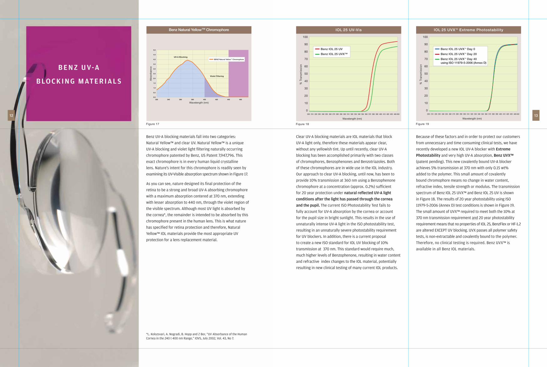
Benz UV-A blocking materials fall into two categories:
Natural Yellow™ and clear UV. Natural Yellow™ is a unique
UV-A blocking and violet light fi ltering naturally occurring
chromophore patented by Benz, US Patent 7,947,796. This
exact chromophore is in every human liquid crystalline
lens. Nature’s intent for this chromophore is readily seen by
examining its UV-Visible absorption spectrum shown in Figure 17.
As you can see, nature designed its fi nal protection of the
retina to be a strong and broad UV-A absorbing chromophore
with a maximum absorption centered at 370 nm, extending
with lesser absorption to 440 nm, through the violet region of
the visible spectrum. Although most UV light is absorbed by
the cornea*, the remainder is intended to be absorbed by this
chromophore present in the human lens. This is what nature
has specifi ed for retina protection and therefore, Natural
Yellow™ IOL materials provide the most appropriate UV
protection for a lens replacement material.
*L. Kolozsvari, A. Nogradi, B. Hopp and Z Bor, “UV Absorbance of the Human Cornea in the 240 t 400 nm Range,” IOVS, July 2002, Vol. 43, No 7.
Clear UV-A blocking materials are IOL materials that block
UV-A light only, therefore these materials appear clear,
without any yellowish tint. Up until recently, clear UV-A
blocking has been accomplished primarily with two classes
of chromophores, Benzophenones and Benzotriazoles. Both
of these chromophores are in wide use in the IOL industry.
Our approach to clear UV-A blocking, until now, has been to
provide 10% transmission at 360 nm using a Benzophenone
chromophore at a concentration (approx. 0.2%) suffi cient
for 20 year protection under natural refl ected UV-A light
conditions after the light has passed through the cornea
and the pupil. The current ISO Photostability Test fails to
fully account for UV-A absorption by the cornea or account
for the pupil size in bright sunlight. This results in the use of
unnaturally intense UV-A light in the ISO photostability test,
resulting in an unnaturally severe photostability requirement
for UV blockers. In addition, there is a current proposal
to create a new ISO standard for IOL UV blocking of 10%
transmission at 370 nm. This standard would require much,
much higher levels of Benzophenone, resulting in water content
and refractive index changes to the IOL material, potentially
resulting in new clinical testing of many current IOL products.
Because of these factors and in order to protect our customers
from unnecessary and time consuming clinical tests, we have
recently developed a new IOL UV-A blocker with Extreme
Photostability and very high UV-A absorption, Benz UVX™
(patent pending). This new covalently bound UV-A blocker
achieves 5% transmission at 370 nm with only 0.15 wt%
added to the polymer. This small amount of covalently
bound chromophore means no change in water content,
refractive index, tensile strength or modulus. The transmission
spectrum of Benz IOL 25 UVX™ and Benz IOL 25 UV is shown
in Figure 18. The results of 20 year photostability using ISO
11979-5-2006 (Annex D) test conditions is shown in Figure 19.
The small amount of UVX™ required to meet both the 10% at
370 nm transmission requirement and 20 year photostability
requirement means that no properties of IOL 25, BenzFlex or HF-1.2
are altered EXCEPT UV blocking. UVX passes all polymer safety
tests, is non-extractable and covalently bound to the polymer.
Therefore, no clinical testing is required. Benz UVX™ is
available in all Benz IOL materials.
% T
rans
mis
sion
100
90
80
70
60
50
40
30
20
10
0
Wavelength (nm)
200 210 220 230 240 250 260 270 280 290 300 310 320 330 340 350 360 370 380 390 400 410 420 430 440 450
IOL 25 UV-Vis
Benz IOL 25 UV
Benz IOL 25 UVX™
Figure 18
% T
rans
mis
sion
100
90
80
70
60
50
40
30
20
10
0
Wavelength (nm)
IOL 25 UVX™ Extreme Photostability
Benz IOL 25 UVX™ Day 0
Benz IOL 25 UVX™ Day 20
Benz IOL 25 UVX™ Day 40using ISO 11979-5-2006 (Annex D)
Figure 19
200 210 220 230 240 250 260 270 280 290 300 310 320 330 340 350 360 370 380 390 400 410 420 430 440 450
B E N Z U V-A
B LO C K I N G M AT E R I A L S
Figure 17
5.0
320 340 360 380 400 420 440 460
Wavelength (nm)
Ab
sorb
ance
4.5
4.0
3.5
3.0
2.5
2.5
1.5
1.0
0.5
0.0
Benz Natural Yellow™ Chromophore
UV-A Blocking
Violet Filtering
BENZ Natural Yellow™ Chromophore

M AC H I N I N G
R E C O M M E N DAT I O N S
14 15
Benz hydrophilic IOL materials can be easily machined to give
excellent surface quality by using the proper machining conditions
and sharp, proper geometry diamond tools. Conditions and tools
are very important and must be controlled for consistent results.
Hydrophilic acrylic IOL materials are glassy polymers and machine
similar to contact lens plastics. Tables 4, 5 and 6 show a
summary of tool and machining parameter recommendations.
Using larger tool diameter, greater depth of cut or faster feed
rate than recommended can reduce the effective expansion of
the material because of induced stress into plastic. To ensure the
highest yield, we recommend that each manufacturer verify the
radial and linear expansion values given for each lot using their
own manufacturing and testing procedures.
Benz Hydrophobic materials require cryogenic conditions for optimum
machining. Cryogenic temperatures can be easily achieved using
commercially available freezing devices that can be attached to the
spindle of your existing lathes. Blanks are mounted on a special
mandrel using moisture (see Figure 20). The mandrel is cooled to
at least -20°C using a vortex freeze station. Once the mandrel is
cooled, it is placed in the lathe collet that is fi tted with a cryogenic
unit. The surface of the blank must be maintained at -20°C or below.
The blow-off air must also be adjusted to the same temperature
and dry (<-50°F dew point). Use the cutting parameters in Tables 7
and 8.
Our newest product, the IOL 25 Universal blank is provided as a
molded disk, similar to the HF-1 universal blank and precision
blocked on a disposable bar coded mandrel. The product features
a hollow mandrel for convenient in-process QC of the optics.
The haptic disk has a 5° angulation or 0° angulation (see
Figure 21).
Polish Free Manufactured Dry LensFigure 21Figure 20
Tool Radius Top Rake Relief
Rough Cut Tool 0.40 mm 0°/-2.5° 15°
Finish Cut Tool 0.30 mm 0°/-2.5° 15°
Table 4
Lathe Tools
Lathe Parameters
Rough Cut Fine Cut
Speed (rpm) 10,000 Speed (rpm) 9,500
Tool Feed (mm/min) 89 Tool Feed (mm/min) 26
Depth of Cut (mm) 0.35 Depth of Cut 0.12
Blank Surface Temp (C°) <-20° Blank Surface Temp (C°) <-20°
Table 5
Benz IOL25 UV and BenzFlex 26
Table 6
Rough Fine Milling Milling 1st pass 2nd pass
Speed (rpm) 9,000 7,500 50,000 55,000
Tool Feed (mm/min) 33 15 80 88
Depth of Cut (mm) .06 .04 0.10
IOL 25 Universal Blank
Lathe & Milling Parameters
Lathe Parameters
Rough Cut Fine Cut
Speed (rpm) 9,000 Speed (rpm) 9,000
Tool Feed (mm/min) 18 Tool Feed (mm/min) 10
Depth of Cut (mm) 0.13 Depth of Cut 0.07
Blank Surface Temp (C°) <-20° Blank Surface Temp (C°) <-20°
Table 7
HF-1.2 Natural Yellow™
Milling Parameters
Rough Cut Fine Cut
Speed (rpm) 50,000 Speed (rpm) 50,000
Tool Feed (mm/min) 30 Tool Feed (mm/min) 45
Blank Surface Temp (C°) <-20° Blank Surface Temp (C°) <-20°
Table 8
HF-1.2 Natural Yellow™
Tool Radius
Rough Cut Tool .20 mm
Finish Cut Tool .20 mm
Lathe Tools*
*controlled wave tools required
Rough Fine
Speed (rpm) 12000 11500
Tool Feed (mm/min) 60 25
Depth of Cut (mm) .06 .04
Lathe Parameter*
*Opto Form 80 Lathe
Milling Parameters
• Equipment, Optomill 363
• 0.400mm x 1.2mm Diamond Endmill (Wiediam Diamonds)
• 1st & 2nd Cut Feed, 88mm/min, 80,000 rpm
• 3rd Cut Feed, 91mm/min, 90,000 rpm
• 1st Cut Stops 0.050mm ( approximately 0.250mm depth)
shy of breaking through to wax
• 2nd Cut Goes 0.050mm ( approximately 0.350mm total)
past the lens into the wax
• 3rd Cut Backs off 0.030mm depth, with a radial cut of
0.030 – 0.040mm
• Cycle time, 150 seconds
Environmental
70 ± 3°F (21 ± 2 °C)
35 ± 3% RH
Polish Free Manufacturing Conditions
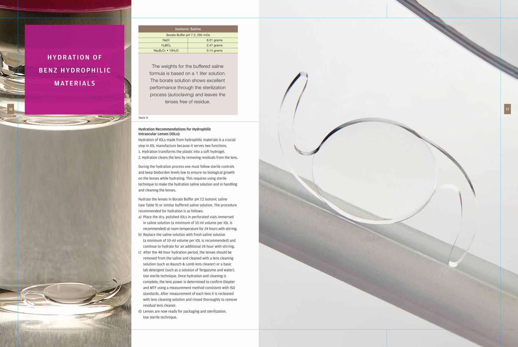
Hydration Recommendations for Hydrophilic Intraocular Lenses (IOLs):
Hydration of IOLs made from hydrophilic materials is a crucial
step in IOL manufacture because it serves two functions.
1. Hydration transforms the plastic into a soft hydrogel.
2. Hydration cleans the lens by removing residuals from the lens.
During the hydration process one must follow sterile controls
and keep bioburden levels low to ensure no biological growth
on the lenses while hydrating. This requires using sterile
technique to make the hydration saline solution and in handling
and cleaning the lenses.
Hydrate the lenses in Borate Buffer pH 7.2 isotonic saline
(see Table 9) or similar buffered saline solution. The procedure
recommended for hydration is as follows:
a) Place the dry, polished IOLs in perforated vials immersed
in saline solution (a minimum of 10 ml volume per IOL is
recommended) at room temperature for 24 hours with stirring.
b) Replace the saline solution with fresh saline solution
(a minimum of 10-ml volume per IOL is recommended) and
continue to hydrate for an additional 24 hour with stirring.
c) After the 48 hour hydration period, the lenses should be
removed from the saline and cleaned with a lens cleaning
solution (such as Bausch & Lomb lens cleaner) or a basic
lab detergent (such as a solution of Tergazyme and water).
Use sterile technique. Once hydration and cleaning is
complete, the lens power is determined to confi rm Diopter
and MTF using a measurement method consistent with ISO
standards. After measurement of each lens it is recleaned
with lens cleaning solution and rinsed thoroughly to remove
residual lens cleaner.
d) Lenses are now ready for packaging and sterilization.
Use sterile technique.
H Y D R AT I O N O F
B E N Z H Y D R O P H I L I C
M AT E R I A L S
16 17
The weights for the buffered saline
formula is based on a 1 liter solution.
The borate solution shows excellent
performance through the sterilization
process (autoclaving) and leaves the
lenses free of residue.
Table 9
Borate Buffer pH 7.2; 295 mOs
NaCl 8.01 grams
H3BO3 2.47 grams
Na2B4O7 • 10H2O 0.14 grams
Isotonic Saline
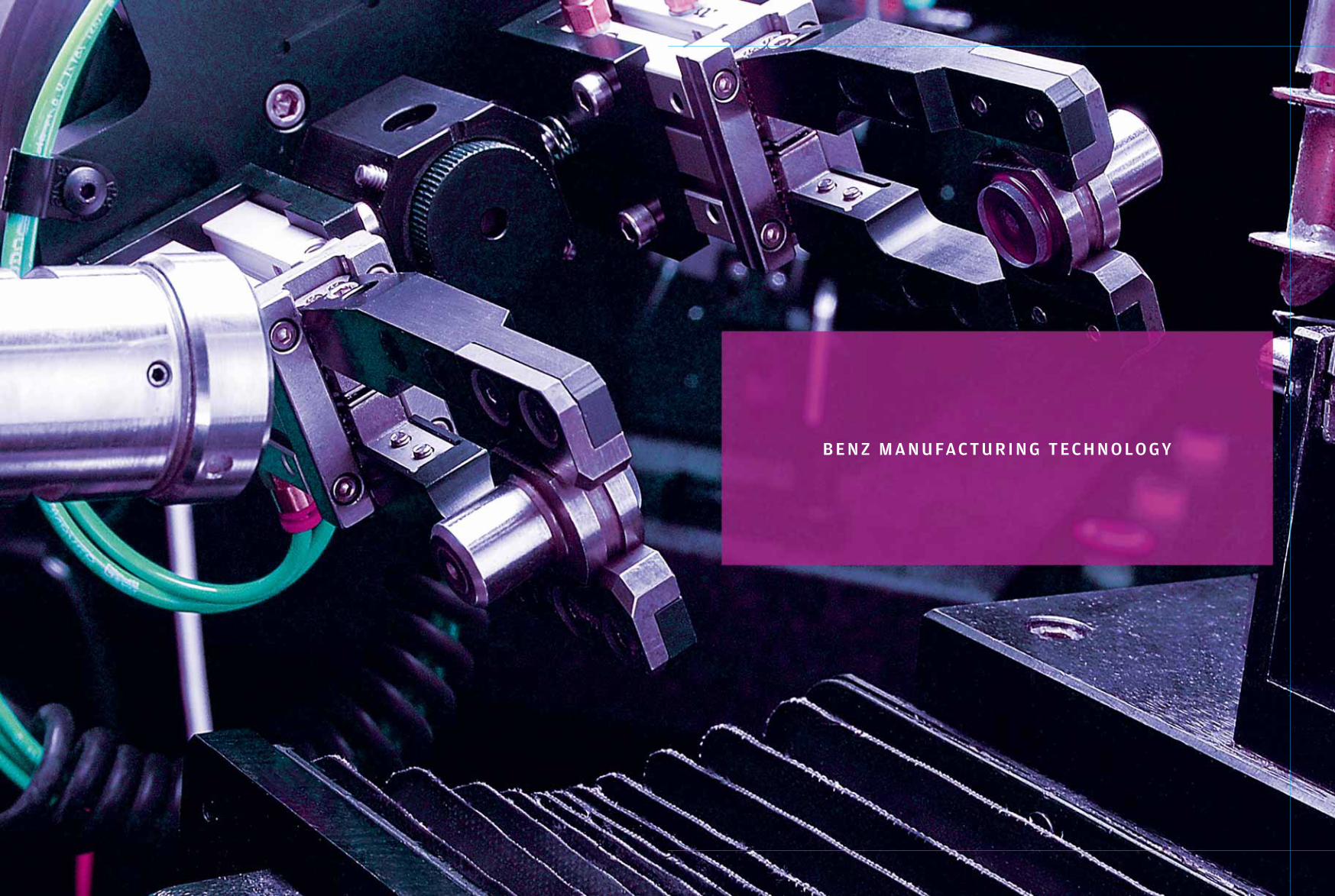
B E N Z M A N U FAC T U R I N G T E C H N O LO GY

Precision and productivity have always been key ingredients
for the success of lens manufacturing, both contact lenses
and IOLs. Today a modern CNC lathe can produce highly
complex geometries with ultra smooth surfaces. These lathes
provide excellent precision for one step, but once the part is
removed from the collet, precision is lost. Therefore, the lathe’s
precision has not necessarily resulted in ultra precision lenses
because the precision of front side machining is lost during
each of two discrete mechanical steps: blocking and second
side machining. Signifi cant precision is lost during these steps
as the part moves from collet-to-collet. Before the total lens
manufacturing process can become very precise, collet-to-
collet position repeatability must be improved. We have solved
the problem of collet-to-collet precision by using technology
specifi cally developed to address the two components of collet
precision: run-out and position.
Collet run-out occurs because the collet’s center of rotation
does not match the lathe spindle’s center of rotation. This
mismatch of rotational symmetry typically produces a collet
run-out of 20-40 microns. This loss in precision is compounded
through blocking and second side machining (3 more collets).
The Benz spindle/collet assembly eliminates this inaccuracy.
In the Benz spindle the mismatch of the collet to its spindle’s
spin center is eliminated by precision lapping the collet cone
into the spindle shaft until reaching the desired spindle/collet
run-out. A portion of the exhaust air from the spindle is also
redirected through the collet to prevent swarf from altering
the tolerance of the cone-collet surface. The Repeatability of
Total Indicated Run-out (TIR) of a Benz Precision Steel mandrel
during 10 repeated collet loads on a 4-Axis Lathe, using the
Benz spindle/collet Assembly is shown in Table 10.
The second component of collet-to-collet precision is
repeatability of position. We have solved this by designing
a precision dead-length collet and a precision steel mandrel
(the blank is mounted with wax onto the mandrel’s
surface for fi rst side machining), see Figure 24 and 25.
Using this precision position dead-length system and precision
dimension blanks, it is no longer necessary to measure the
position of the surface before beginning fi rst side machining.
This saves time on every lathe machining cycle. Figure 24
shows a picture of the Benz mandrel with a precision blank
attached and the same mandrel and the centering ring used for
wax mounting the blank into the mandrel.
The Benz spindle with precision lapped dead-length collet,
precision mandrels and blank mounting centering rings are all
available as technology products from Benz R&D.
AC H I E V I N G
C O L L E T TO C O L L E T
P R E C I S I O N
20 21
Figure 24
1 0.0036
2 0.0038
3 0.0039
4 0.0036
5 0.0036
6 0.0041
7 0.0034
8 0.0025
9 0.0036
10 0.0029
Average 0.0035
SD 0.0005
Table 10
Reading # Total Indicated Run (mm)
Figure 25
Ø0.4995±0.0001
[Ø12.687mm±0.0025mm]

Optical blocking was invented and patented worldwide by
Benz Research and Development in 1994. Since building
our fi rst machine in 1994, we have greatly expanded the
functions and overall capabilities of the Optical Blocker for
manufacturing contact lenses and IOLs. The Benz Optical
Blocker today represents the only commercially available
blocking interface between fi rst side and second side
machining that achieves accuracy and precision comparable
to the lathes currently used in manufacturing. The Benz
Optical Blocker is designed and built to deliver unequaled
accuracy and precision through years of trouble free use.
Our original blocker is still in use at Benz R&D.
The new Laser Blocking feature reduces cycle time and
provides in-process QC of aspheric optics.
The Benz Optical Blocker provides many manufacturing
advantages and can be used as a stand-alone machine
operated manually, by robot or fully integrated into an
automated system, Benz Integrated Lens Manufacturing.
Optical Blocking eliminates the following common manufacturing
problems associated with blocking: Prism error, centration
variations, and center thickness variations.
Increased yield with improved quality are the obvious benefi ts
of Optical Blocking. Additional benefi ts to your manufacturing
competitiveness that may not be obvious are:
• Automatically provides micron accurate radius measurement
• Measures of spherical radius as well as major, minor axis of
toric lenses with a permanent record of measurements
• Laser profi les of aspheric optics
• Automatically rejects base curves that do not meet tolerance
you set
• Automatically calibrates your lathes for radius and sphere to
tolerances that you set and provides a real time process control
record of lathe calibrations
Specifi c Features of the Optical Blocker
1. Measures radius of curvature with + 2 microns accuracy
2. Measures both major and minor cylinder radii of toric lenses
with + 2 micron accuracy
3. Positions apex of concave and convex lenses with + 2 microns
in X, Y and Z
4. Concentric blocking – average max – min variations in edge
thickness of 5 microns, see Table 11
5. Cylinder alignment of toric lenses on second side mandrel to
better than 0.5° accuracy
6. Constant center thickness of lenses + 2 microns
7. Automatically calibrates lathes for radius and sphere
8. Provides “dead-length” apex blocking – constant distance between
second side mandrel base and apex of mounted fi rst side lens
9. Includes full automatic, semi-automatic and manual mode
of operation
10. Laser profi les of aspheric optics
Benz Optical Cryo Blocker
Our newest Optical Blocking CNC device is the Optical Cryo
Blocker. In order to achieve <10 micron concentric accuracy
when blocking the HF-1.2 and HF-2 Universal blanks Benz has
developed the fully automated Benz Cryo Blocker. High MTF
lenses require concentric accuracy when blocking the fi rst
side optic. The Optical Cryo Blocker can feed 2 MLC’s in an
integrated cell (ILM-C). The blocking sequence is shown below.
OPTICAL BLOCKING &
OPTICAL CRYO BLOCKING
22 23
Figure 26
Video Haptic Inspection
Table 11
Calibration Values (X And Y Axis) for aTypical Set-Up Sequence on the Optical Blocker
Part # Center (mm) Y1 (mm) X2 (mm) Y2 (mm) X1 (mm) Max-Min
1 0.158 0.135 0.135 0.131 0.131 0.004
2 0.153 0.145 0.147 0.146 0.142 0.005
3 0.155 0.145 0.146 0.141 0.141 0.005
4 0.155 0.143 0.147 0.142 0.140 0.007
5 0.152 0.142 0.145 0.141 0.141 0.004
Average 0.155 0.142 0.144 0.140 0.139 0.005
SD 0.002 0.004 0.005 0.006 0.005 0.001
Note the standard deviation of total position (max-min) repeatability.
Dispensing Blocking Water
Freeze Blocking the Universal Blank
Finished Blocked Part Ready for Machining
Optical Cryo Blocker

Automated Cryo Manufacturing has been made possible by
the development of the Benz Optical Cryo Blocker. As the
starting point, the HF-1.2 and HF-2 Universal Blanks have
eliminated fi rst side machining of hydrophobic IOLs. The
next step in development of Integrated Lens Manufacturing
for hydrophobic IOLs is integrating the Optical Cryo Blocker
with Cryo MLC’s. ILM-C is shown on the opposite page. In
ILM-C, 100 part trays of HF-1.2 or HF-2 Universal Blanks are
the raw material input. These are fully inspected and bar
coded trays of specifi c diopter parts. Approximately 100
microns of material is removed in two passes and the haptic
is milled.
The blocker cycle is <60 sec from picking the Universal Blank
from its tray and blocking on a cryo mandrel and cooled to
-28°C. ILM-C, with its robotic part handling, keeps 2-MLC’s
working at full capacity. When the MLC fi nishes cutting the
lens the cryo mandrel is moved to an automatic station
that warms the mandrel, removes the fi nished lens to a
special container, and cleans the mandrel to start another
manufacturing cycle.
The productivity of ILM-C is >140,000 fi nished lenses per year
when operated 16 hours/day, 250 days/year. One operator is
required per shift. Guaranteed yield is 96%.
ILM-C
CRYO MANUFACTURING
OF HF-1.2 & HF-2
24 25
Cryo Blocker
ILM CRYO
Mill / LatheCombo 1
Mill / LatheCombo 2
CleaningStation
Robot

Integrated Lens Manufacturing (ILM-3) is a lens manufacturing
process developed and refi ned over the past 13 years.
Benz Research and Development has spent millions of
dollars developing the component systems and automation
technology used in ILM. In ILM each lens manufactured has
a discrete identity. This identity is defi ned by order number
and the bar code numbers associated with each portion of the
manufacturing process:
• First side manufacturing and blocking;
• Second side manufacturing, polishing and hydration
• Inspection, packaging and labeling
All data associated with each lens, including the order, and
all manufacturing data from each step is saved in the Oracle 10
database of ILM-3.
The Benz Automation Program is a large C program that
coordinates all automation steps and storage of all data
associated with each order including machining parameters
created by the front end Design Program for use in each
manufacturing step. The Benz Automation Program also
coordinates the activities and movements of the tray feed
system, blank mounting, lathes, optical blocker, drill, deblocker
and robots. Figure 27 illustrates the fl ow of information and
instructions including all robot moves and bar code reads
coordinated by the automation program.
ILM is designed for robotic handling of parts. Manual
part handling can be substituted for robots, but with a
substantial loss in productivity. ILM operated with robots will
require approximately 1/8 of the manpower of a traditional
manufacturing process. Also, all lathe calibration for radius
and sphere are automatically performed using ILM. This
further reduces total manpower because all lathe calibration
is done manually in a traditional manufacturing process.
ILM utilizes the following manufacturing technology in a fully
integrated system:
• The Benz precision spindle/collet assembly with Benz mandrels
• The Benz Optical Blocker with high speed Laser Blocking
• The Benz IOL Drill
• The Benz Tray Feed System
• The Benz Automatic Blank Mounting System
• The Benz Automatic Deblocking System
• The Benz Solvent Cleaning System
• The Benz ILM Automation Program utilizing an Oracle 10
database
• Custom ILM part handling robot effectors
• Re-calculation of the second side radius for every part based
on the actual measured fi rst side radius
• Real-time re-calibration of all lathes for radius and sphere
• Design front end program for spherical and toric lens
designs that is accessible for further customization by each
manufacturer.
• Windows-based operator interface for all manufacturing
operations including Order-Entry, Maintenance, Quality
Control, Inspection, and Auto Calibration
• Automatic laser profi ling of aspheric surfaces
• Automatic video inspection of haptic milling
ILM-3 Manufacturing Sequence
The fi rst step to starting ILM-3 is loading clean mandrels in
trays into the Tray Feed System, making sure that the
vibratory hopper is full of blanks and the wax applicators on
the Automatic Blank Mounting Machine and Optical Blocker
are full. The next step is to calibrate the lathes Y-Axis to the
Optical Blocker Z-Axis and verify the concentricity of the
Blocker. This will take 1 hour or less. Now IOL lenses can be
ordered in any combination from singles to hundreds at the
Order Entry Terminal. Finished lenses on their second side
mandrels and used fi rst side mandrels are returned to their
trays in the Tray Feed System. Each tray of mandrels and
lenses can be conveniently handled and cleaned using the trays
with the Benz Solvent Cleaning System.
I N T E G R AT E D
L E N S M A N U FAC T U R I N G
( I L M )
26 27
ILM-3 Systems Operations:
The ILM system has been designed for both function and flexibility. ILM-3 also allows
the system manager to easily add or delete equipment under its control while remaining in
continuous operation. The process manager can select each machine mode, thereby
optimizing operation time and allowing for other functions like maintenance, or diamond change,
that takes a single machine off line while the remaining equipment remains in automation.
Adding cells and rearranging equipment within cells is easy through the secure operator interface.
There is no limit to the size of the total ILM-3 system imposed by the Benz Automation Program.
Figure 27
AutomationSoftware
& Database
1. Order Entry &Customer ID
3. BlankMounting(Robotic)
4. 1st Side OpticsLathing & Milling
(Robotic)
5. Optical Blocking(Robotic)
9. Hydration & or Inspection
7. 2nd Side OpticsLathing(Robotic)
10. Packaging &Labeling
8. Polishing
2. Lens Design
6. Deblocking& Cleaning
(Robotic)
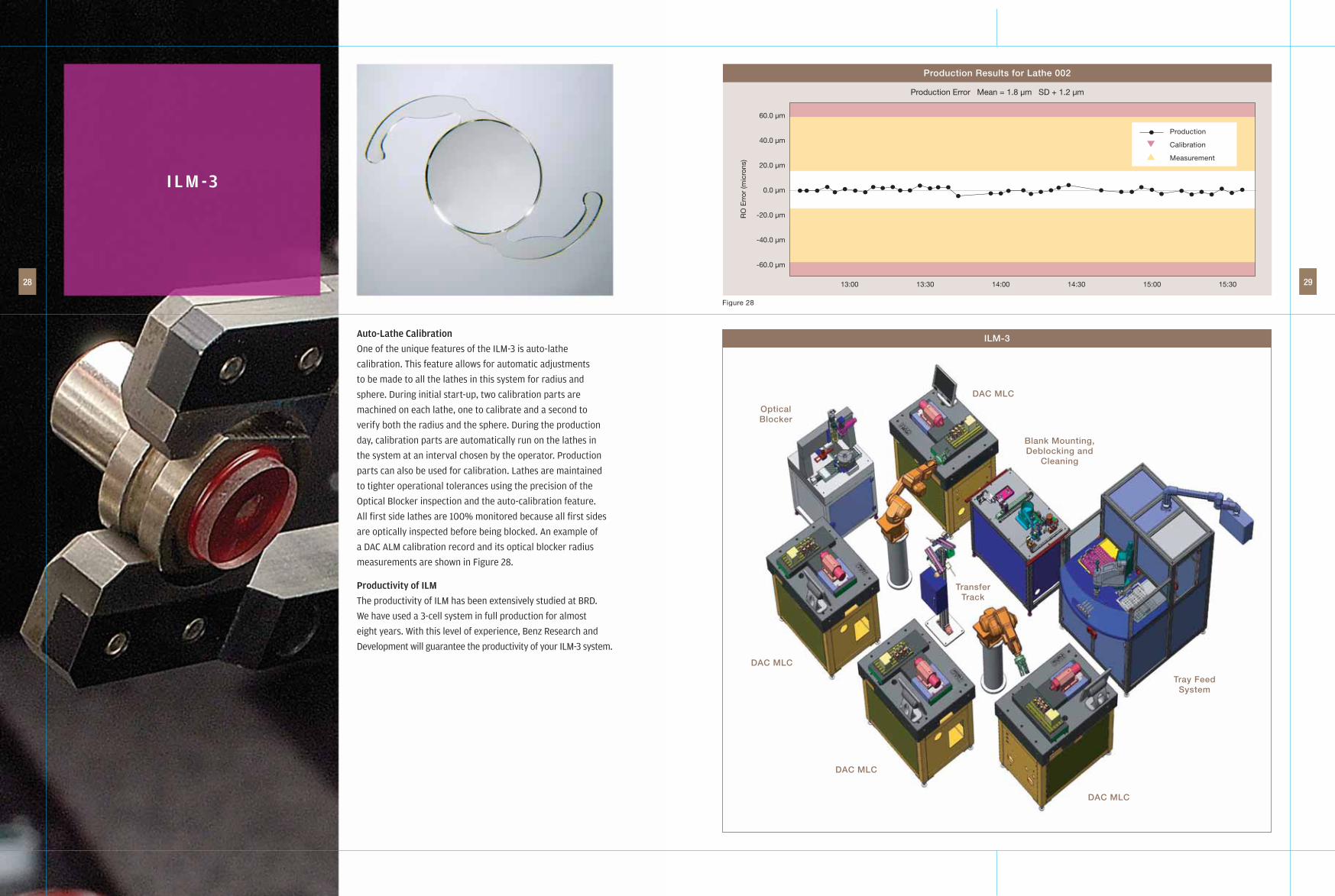
Auto-Lathe Calibration
One of the unique features of the ILM-3 is auto-lathe
calibration. This feature allows for automatic adjustments
to be made to all the lathes in this system for radius and
sphere. During initial start-up, two calibration parts are
machined on each lathe, one to calibrate and a second to
verify both the radius and the sphere. During the production
day, calibration parts are automatically run on the lathes in
the system at an interval chosen by the operator. Production
parts can also be used for calibration. Lathes are maintained
to tighter operational tolerances using the precision of the
Optical Blocker inspection and the auto-calibration feature.
All fi rst side lathes are 100% monitored because all fi rst sides
are optically inspected before being blocked. An example of
a DAC ALM calibration record and its optical blocker radius
measurements are shown in Figure 28.
Productivity of ILM
The productivity of ILM has been extensively studied at BRD.
We have used a 3-cell system in full production for almost
eight years. With this level of experience, Benz Research and
Development will guarantee the productivity of your ILM-3 system.
I L M -3
28 29
Tray FeedSystem
TransferTrack
Blank Mounting,Deblocking and
Cleaning
DAC MLC
DAC MLC
DAC MLC
DAC MLC
OpticalBlocker
ILM-3
60.0 µm
40.0 µm
20.0 µm
0.0 µm
-20.0 µm
-40.0 µm
-60.0 µm
RO
Err
or (m
icro
ns)
13:00 13:30 14:00 14:30 15:00 15:30
Production
Calibration
Measurement
Production Results for Lathe 002
Production Error Mean = 1.8 µm SD + 1.2 µm
Figure 28
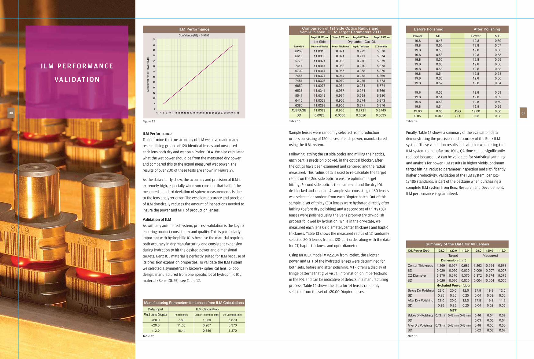
ILM Performance
To determine the true accuracy of ILM we have made many
tests utilizing groups of 120 identical lenses and measured
each lens both dry and wet on a Rotlex IOLA. We also calculated
what the wet power should be from the measured dry power
and compared this to the actual measured wet power. The
results of over 200 of these tests are shown in Figure 29.
As the data clearly show, the accuracy and precision of ILM is
extremely high, especially when you consider that half of the
measured standard deviation of sphere measurements is due
to the lens analyzer error. The excellent accuracy and precision
of ILM drastically reduces the amount of inspections needed to
insure the power and MTF of production lenses.
Validation of ILM
As with any automated system, process validation is the key to
ensuring product consistency and quality. This is particularly
important with hydrophilic IOLs because the material requires
both accuracy in dry manufacturing and consistent expansion
during hydration to hit the desired power and dimensional
targets. Benz IOL material is perfectly suited for ILM because of
its precision expansion properties. To validate the ILM system
we selected a symmetrically biconvex spherical lens, C-loop
design, manufactured from one specifi c lot of hydrophilic IOL
material (Benz-IOL 25), see Table 12.
Sample lenses were randomly selected from production
orders consisting of 120 lenses of each power, manufactured
using the ILM system.
Following lathing the 1st side optics and milling the haptics,
each part is precision blocked, in the optical blocker, after
the optics have been examined and centered and the radius
measured. This radius data is used to re-calculate the target
radius on the 2nd side optic to ensure optimum target
hitting. Second side optic is then lathe-cut and the dry IOL
de-blocked and cleaned. A sample size consisting of 60 lenses
was selected at random from each Diopter batch. Out of this
sample, a set of thirty (30) lenses were hydrated directly after
lathing (before dry polishing) and a second set of thirty (30)
lenses were polished using the Benz proprietary dry-polish
process followed by hydration. While in the dry-state, we
measured each lens OZ diameter, center thickness and haptic
thickness. Table 13 shows the measured radius of 12 randomly
selected 20 D lenses from a 120-part order along with the data
for CT, haptic thickness and optic diameter.
Using an IOLA model # V2.2.34 from Rotlex, the Diopter
power and MTF of the hydrated lenses were determined for
both sets, before and after polishing. MTF offers a display of
fringe patterns that give visual information on imperfections
in the IOL and can be indicative of defects in a manufacturing
process. Table 14 shows the data for 14 lenses randomly
selected from the set of +20.00 Diopter lenses.
Finally, Table 15 shows a summary of the evaluation data
demonstrating the precision and accuracy of the Benz ILM
system. These validation results indicate that when using the
ILM system to manufacture IOLs, QA time can be signifi cantly
reduced because ILM can be validated for statistical sampling
and analysis for power. ILM results in higher yields, optimum
target hitting, reduced parameter inspection and signifi cantly
higher productivity. Validation of the ILM system, per ISO-
13485 standards, is part of the package when purchasing a
complete ILM system from Benz Research and Development.
ILM performance is guaranteed.
I L M P E R F O R M A N C E
VA L I DAT I O N
30 31
Table 12
Data Input ILM Calculation
Final Lens Diopter Radius (mm) Center Thickness (mm) OZ Diameter (mm)
+28.0 7.80 1.269 5.370
+20.0 11.03 0.967 5.370
+12.0 18.44 0.686 5.370
Manufacturing Parameters for Lenses from ILM Calculations
Table 13
Target 11.030 mm Target 0.967 mm Target 0.270 mm Target 5.370 mm
Barcode # Measured Radius Center Thickness Haptic Thickness OZ Diameter
6269 11.0316 0.971 0.272 5.378
6615 11.0338 0.971 0.271 5.374
5775 11.0371 0.966 0.276 5.379
7414 11.0344 0.968 0.270 5.373
6702 11.0341 0.965 0.268 5.376
7455 11.0371 0.964 0.272 5.369
7481 11.0308 0.970 0.275 5.373
6659 11.0276 0.974 0.274 5.374
6538 11.0341 0.967 0.274 5.369
5541 11.0318 0.964 0.268 5.380
6415 11.0328 0.956 0.274 5.373
6380 11.0298 0.956 0.271 5.376
AVERAGE 11.0329 0.966 0.2721 5.3745
SD 0.0028 0.0056 0.0026 0.0035
Comparison of 1st Side Optics Radius andSemi-Finished IOL to Target Parameters 20 D
1st Side Dry Lathe - Cut IOL
Table 14
Power MTF Power MTF 19.8 0.45 19.8 0.59 19.8 0.60 19.8 0.57 19.8 0.58 19.8 0.56 19.8 0.53 19.8 0.53 19.8 0.55 19.8 0.59 19.8 0.63 19.8 0.58 19.8 0.56 19.8 0.58 19.8 0.54 19.8 0.58 19.8 0.63 19.8 0.56 19.8 0.57 19.8 0.54
19.8 0.56 19.8 0.59 19.8 0.51 19.8 0.59 19.8 0.58 19.8 0.59 19.8 0.54 19.8 0.59 19.80 0.60 AVG 19.80 0.60 0.05 0.046 SD 0.02 0.03
Before Polishing After Polishing
Table 15
Summary of the Data for All Lenses
IOL Power (Dpt) +28.0 +20.0 +12.0 +28.0 +20.0 +12.0
Target Measured Dimension (mm)
Center Thickness 1.269 0.967 0.686 1.262 0.964 0.678
SD 0.020 0.020 0.020 0.006 0.007 0.007
OZ Diameter 5.370 5.370 5.370 5.372 5.374 5.375
SD 0.020 0.020 0.020 0.004 0.004 0.005
Hydrated Power (dpt)
Before Dry Polishing 28.0 20.0 12.0 27.8 19.8 12.0
SD 0.25 0.25 0.25 0.04 0.03 0.06
After Dry Polishing 28.0 20.0 12.0 27.8 19.8 11.9
SD 0.25 0.25 0.25 0.04 0.02 0.05
MTF
Before Dry Polishing 0.43 min 0.43 min 0.43 min 0.46 0.54 0.58
SD 0.03 0.05 0.04
After Dry Polishing 0.43 min 0.43 min 0.43 min 0.48 0.55 0.56
SD 0.02 0.03 0.02
Figure 29
Mea
sure
d F
inal
Pow
er (D
pt)
32
30
28
26
24
22
20
18
16
14
12
10
8
6
ILM Performance
Confidence (R2) = 0.9993
6 7 8 9 10 11 12 13 14 15 16 17 18 19 20 21 22 23 24 25 26 27 28 29 30 31 32

The ILM-3 Quality System
The Benz Integrated Lens Manufacturing Process was
developed with quality products in mind and is part of the
overall Quality Management System of Benz Research and
Development. ILM-3 is compliant with the stringent quality
system requirements of ISO 13485, which embraces the
principals of good manufacturing practices and quality
system regulations. These quality standards and regulations
satisfy the specifi c quality management requirements for the
development and manufacture of medical devices.
As a result, ILM-3 is a fully documented, controlled and
validated process that delivers a product of consistently high
quality. ILM-3 is a turn-key process. Currently ILM-3 is fully
validated for automated manufacture of biconvex IOLs from +8
to +35 D. Extensions to this range or optics other than spherical
biconvex such as torics, require only additional validation
tests to be performed not a change in ILM-3. ILM-3 is also fully
validated for statistical verifi cation of power and MTF. Because
of the validated accuracy and repeatability of ILM, 100%
inspection of IOLs for power is not required, only statistical
verifi cation in accordance with your specifi c ANSI AQL Standard.
Profi tability of ILM-3
Using Table 16 you can determine the appropriate gross profi t
potential of an ILM production cell shown in Figure 30.
The following assumptions have been made:
• A 24 hours/day operation (1 hour set-up and calibration,
22.5 hours of production)
• Use 4 DAC MLCs
• Average yields of 98.5% through machining. Yields are
guaranteed and based on our experience manufacturing
semi-fi nished lenses.
Per Day Profi tability for An ILM-3 Four Lathe System
Based on the above example, productivity is 1108 machined
lenses per day at a direct cost of US $2.48 per IOL 25UV lens.
The estimated profi tability [(Productivity x ASP) – Direct Cost =
Profi t] using an average sale price (ASP) per unit of US $20.00
would be about $19,060 per day.
ILM-3 Expandability
The ILM-3 software provides for unlimited expansion of
production cells. No additional software is required to operate
increasingly larger systems. To increase capacity starting with
a 2-lathe ILM-3 system, you simply add 2 more lathes.
To increase capacity starting with a full 4 lathe ILM-3 system
you would need a new ILM-3 System, but with only 2-lathes
to start and no new software, only a faster server.
ILM-3 offers expandability without the headaches of expensive
training, turnover, hourly rate growth and an ever expanding
work force. ILM-3 keeps your cost of goods under control for
years to come.
I L M -3
32 33
BENZ RESEARCH & DEVELOPMENTRegistered to ISO-13485 : 2003File No. A7130
Table 16
Hours – Estimated Daily Item Quantities Cost Description Expense
Number of BLANKS 1125 $1.50 98.5% yield $1,688.00 Per Day 22.5 hrs
Average Production 24hr $15.00 Benefits @ x 1.2 $432.00 Operator Cost x 24
Average Consumable 22.5 hrs $80.00 Including $80.00 Costs Polishing
Subtotal – Cost Per Day $2,200.00
Add Daily Overhead Cost at 25% $550.00
Total Direct Cost Per Day $2,750.00
Daily Output @ 98.5%, 1108 lenses
Direct Cost Per Lens $2.48
Direct Cost of Intraocular Lenses Manufacturedin the ILM-3 System
Temperature 21ºC + 2
RH 37% + 5 at 21ºC
Air 90 psi at -60C Dew Point
2-Lathe System, 12 CFM
4-Lathe System, 20 CFM
Electrical 2-Lathe System, 6 KVA
UPS 4-Lathe System, 10 KAV
208-240V single phase
Environmental Requirements
Figure 30
283˝ [7.200m]
224˝
[5.7
00m
]
Space Requirements ILM-3

B E N Z U N I V E R S A L B L A N K M A N U FAC T U R I N G ( U B M )

Manufacturing hydrophilic IOLs from Benz IOL 25 Universal Blanks
The IOL 25 Universal Blank is a precision molded IOL blank
containing a haptic disk and two precision molded optical
surfaces, optically blocked onto a low run-out disposable mandrel
containing a 2D barcode. The advanced features of Integrated
Lens Manufacturing (ILM) are built into each Universal Blank,
providing the manufacturer a means to achieve the same
production effi ciency and manufacturing precision as ILM.
Drawings of the IOL 25 Universal Blank and Mandrel are shown
in Figures 9 and 10. Front and side views of actual Universal
Blanks shown in Figures 31 and 32.
As you can see from the above images, the Universal Blank
looks very much like a part in ILM production that is about to be
second side fi nished cut and milled, that is because it has been
produced with all of the technology of ILM and more, including
extremely accurate optical blocking. Also, the data contained in
ILM for an individual part at this stage of production is provided
with each shipment of Universal Blanks, including the addition of
a full optic inspection that is not available from ILM or any other
IOL manufacturing process for that matter. The IOL 25 Universal
Blank represents a unique assembly of highly advantageous
manufacturing technologies in a ready to use form that is produced
by Benz Research and Development’s Quality Manufacturing
Team in the high volumes demanded by our customers to meet
the ever growing IOL market. Custom optics are also available
with appropriate minimum volume contracts.
The Benz Universal Blank requires a minimum of capital
investment to achieve a new level of precision manufacturing
and only a modest additional investment to achieve fully
automated precision machining. The minimum requirement for
high precision machining is a very low TIR dead stop collet/spindle
of 0.002 mm or better. An example of such a spindle is shown in
Figure 33.
High precision, Fully Automated Manufacturing can be
achieved using a DAC MLC with Benz Autoloader and data
acquisition software. Benz Research and Development
provides a fully validated Universal Blank Manufacturing
(UBM) System utilizing the DAC MLC. We will provide all
documentation for EN13485 validation and certifi cation
plus a production deblocking and cleaning system (100
parts per cycle) at no charge. Also, with the UBM system,
polishing time is approximately 14 hours using the Benz Dry
Polishing Process. Polish free lenses can be made from the
Universal Blank using the Optoform 80 Lathe (see Global
Contact, issue 2, 2013, article New Methods in Hydrophilic
IOL Manufacturing).The Universal Blanks are shipped in foil
packaging in ready to use barcoded trays of 100 parts, see
Figure 34.
Figure 35 shows 5 trays of Universal Blanks being loaded into
the autoloader. Please, read our article in Global Contact on
Automated Manufacturing using the IOL 25 Universal Blank.
U N I V E R S A L B L A N K
M A N U FAC T U R I N G ( U B M )
36 37
Figure 31 Figure 33
Figure 35Figure 34
Figure 32

Benz Research and Development has implemented a major program towards renewable energy and conservation. Beginning
in the summer of 2007, Benz Research and Development installed a 25,000 watt solar panel array and began a comprehensive
program to examine energy use. This has resulted in several important energy conservation projects that have reduced our
electrical power demand by 50,000 watts. Our current energy conservation projects include 250 KW of gas turbine power
combined with a high effi ciency heat recovery system to provide 1,080,000 BTUs of air conditioning via LiBr absorption
chillers and 400,000 BTUs of process hot water. The overall effi ciency of our Combined-Heat-and-Power system (CCHP) is
approximately 70%, which has helped us to further trim our electrical power demand by 100,000 watts. benzrd.com