Interpretations No.1to ANSI/ASMEB31
44
,::: -.,( .. .I •. '. ..' Interpretations No.1 to ANSI/ASME B31.3 (This supplement is not part of the ANSII ASME 831.3. It is included for infonnation only.) It has been agreed to publish Interpretations issued by the B31 Committee concerning B31.3 as part of the subscription service. This supplement includes Interpretations concerning B31 J issued between January 1,1980, and December 31,1982. Future versions of this supplement will cover inquiries issued over 1 year periods. Each Interpretation applies to the Edition or Addenda at the time of issuance of the Interpretation. Subsequent revisions to the Code may have superseded the reply.
Transcript of Interpretations No.1to ANSI/ASMEB31

,::: ~ -.,( ~ ..~ . I •. '.
\~> ..'
Interpretations No.1 to ANSI/ASME B31.3
(This supplement is not part of the ANSIIASME 831.3. It is included for infonnation only.)
It has been agreed to publish Interpretations issued by the B31 Committee concerning B31.3 as partof the subscription service. This supplement includes Interpretations concerning B31 J issued betweenJanuary 1,1980, and December 31,1982. Future versions of this supplement will cover inquiries issuedover 1 year periods. Each Interpretation applies to the lat~st Edition or Addenda at the time of issuance ofthe Interpretation. Subsequent revisions to the Code may have superseded the reply.

".. ' .
;. . ~
B31.3 Interpretations No. I
Interpretation: 1·1
Subject: Table 327.4.IA, Umitations on Imperfections in Welds
1-1,1·:
Date Issued:
File:
February 8. 1980
1426
Question: Does Note F to Table 327.4.1 A al10w concavity of the root surface of a depth equivalentto the actual external weld reinforcement, prOVided the reinforcement does nol exceed the maximum al·lowed by the Code?
Reply: It is the opinion of the Committee thaI Note F to Table 327.4.1 A allows concavity of the rOOlsurface of a depth equivalent to the actual external weld reinforcement, provided the reinforcement doesnot exceed the maximum allowed by the Code.
Interpretation: 1·2
Subject: 337, Pressure Tests
Date Issued: April II, 1980
File: 1428
Question (1): When pressure testing, does 337 reqUire the test pump to be isolated from the pipingbeing tested when the test pressure has been attained?
Reply (l): It is the opinion of the Committee that the Code does not require isolation of the testpump. It is not the intent of the Code to require specific equipment which may be necessary to perform theexaminations and tests required by the Code.
Question (2): What are the acceptance criteria for pressure tests performed in accordance withANSI/ASME B31.3?
Reply (2): It is the opinion of the Committee that the acceptance criterion is a visual examination forleakage to verify that there are no leaks in the tested piping.
Question (3): In reference to 337.1, what are some examples of "minor repairs or additions"?
Reply (3): It is the opinion of the Committee that minor repairs or additions are those which wouldnot affect the load carrying ability or leak tightness when precautionary measures are taken to assure soundconstruction.
3

1·3
Interpretation: )-3
B31.3 Interpretations No. I
Subject:
Date Issued:
File:
302.2.4, Allowances for Pressure and Temperature Variations
April 11, 1980
1434
Question (1): What is the reason for allowances for occasional variations of pressure and temperature above design conditions in ANSI/ASME B31.3?
Reply (l): As stated in ANSI/ASME B31.3. "Occasional variations of pressure or tempera ture. orboth, above operating levels are characteristic of certain services". It is the opinion of the Committee thatthis Code recognizes that occasional loads do not require the same factor of safety on stress as long timesustained loads. ANSI/ASME B31.3 allows an increase in allowable stress when designing for such varia·tions prOVided all of the limitations of 302.2.3 (now 302.2.4) are adhered to.
Question (2): Is the allowance normally used in refinery and offshore facilities design?
Reply (2): The Committee does not have statistics on the frequency of application of various Codeprovisions by users. It is the opinion of the Committee that occasional variations are normally designed forin certain services in petroleum refineries and offshore facilities.
Question (3): Is it permissible to apply 302.2.3 (now 302.2.4) to offshore piping installations designed in accordance with ANSI/ ASME B3I.3?
Reply (3): Yes. It is the opinion of the Committee that all provisions of ANSI/ASME B31.3 are applicable to all facilities covered by the scope of the Code unless there is a specific statement to the contrary.
The reader is directed to the Introduction and Scope of the Code which state, "The designer is cau.tioned that the Code is not a design handbook. The Code does not do away"With the need for the designeror competent engineering judgement" and "Where service requirements necessitate measures beyond theCode ~imum, such measurts shall be specified by the engineering design. Where so specified, the Coderequires that they be accomplished."
4

r
"
831.3 Interpretations No.1
Interpretation: 1-4
Subject: 337.1, Pressure Tests
1-4, 1·5
Date Issued:
File:
April II, ]980
]435
Question (]): Does the test referred to in 337.1 apply only to newly constructed piping systems?
Reply (1): Yes. It is the opinion of the Committee that the test required by 337.J applies only tonewly constructed piping systems, whether in the original installation or replacement in or of existingfacilities.
Question (2): Does the test referred to in 337.1 apply only to leakage to the environment?
Reply (2): Yes. It is the opinion of the Committee that the test referred to in 337.] applies only toleakage to the environment.
Interpretation: 1-S
Subject: 336.6.1 (c), Progressive Examination
»ate Issued: April 11, 1980
File: 1444
Question: At what percentage repair rate does ANSI/ASME B31.3 permit one to revert to spotradiography, upon improvement of the quality of welds, in a piping system requiring spot radiography ofwelds but which has been subjected to 100% radiography due to poor weld quality?
Reply: ANSI/ASME B31.3 does not set down a repair rate percentage at which time the user may reotum to a random or spot percentage. 336.6.l(c), Progressive Examination, requires that all welds representedby the original examination be repaired or replaced as per 336.6.](c)(]) or 336.6.I(c)(2). It is the opinionof the Committee that when this is completed, one may revert (0 the original examination requirements.
5 c'
----- ---- -----
0i.. ~. ,
~ '. 0'
': .,~, -','. _. '... \: ....~.:.I .... :.. ... :.
1-6 B31.3 Interpretations No.1
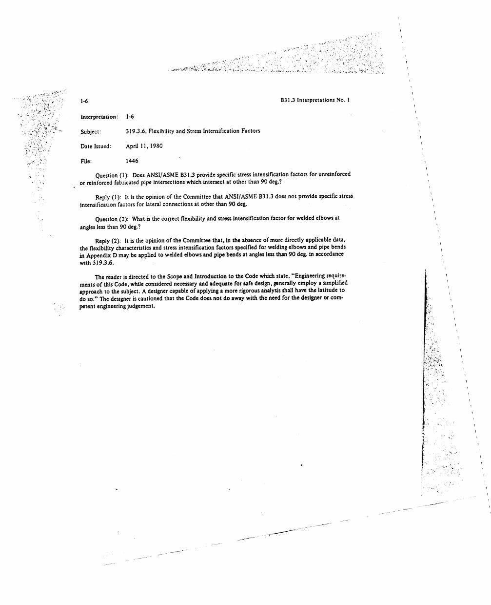
Interpretation: 1·6
Subject: 319.3.6, Flexibility and Stress Intensification Factors
Date Issued: April 11, 1980
File: 1446
Question (1): Does ANSI/ASME 831.3 provide specific stress intensification factors for unreinforcedor reinforced fabricated pipe intersections which intersect at other than 90 deg.?
Reply (1): It is the opinion of the Committee that ANSI!ASM E B31.3 does not provide specific stressintensification factors for lateral connections at other than 90 deg.
Question (2): What is the co~rect flexibility and stress intensification factor for welded elbows at
angles less than 90 deg.?
Reply (2): It is the opinion of the Committee that, in the absence of more directly applicable data,the flexibility characteristics and stress intensification factors specified for welding elbows and pipe bendsin Appendix D may be applied to welded elbows and pipe bends at angles less than 90 deg. in accordancewith 319.3.6.
The reader is directed to the Scope and Introduction to the Code which state, "Engineering requirements of this Code. while considered necessary and adequate (or safe design. generally employ a simplifiedapproach to the subject. A designer capable of applying a more rigorous analysis shall have the latitude todo so," The designer is cautioned that the Code does not do away with the need for the designer or competent engineering judgement.
ti.·.··t,' ."-
r; .;,.:\'
•••~ I
..'
'.
-----
---,---
---------

B31.3 Interpretations No.1 1-7. 1-8
Interpretation: 1-7
Subject:
Date Issued:
File:
Flexibility and Stress Intensification Factors for an ANSI B16.9 Butt-Welding Tee
April 11,1980
1450
((.'. ~. '
Question (1): What are the ANSI!ASME B31.3 flexibility and stress intensification factors for anANSI B16.9 butt-welding tee with a crotch radius less than 12.5% of the branch outside diameter?
Question (2): What are the ANSI/ASME B31.3 flexibility and stress intensification factors for anANSI Bi 6.9 butt·welding tee with a crotch thickness less than 150% of the nominal wall thickness of theheader pipe?
Reply: It is the opinion of the Committee that extruded ANSI B16.9 welding tees with a crotchradius less than 12.5% of the branch diameter may use flexibility characteristics and stress intensificationfactors for an extruded welding tee, provided the crotch thickness is less than 150% of the nominal wallthickness of the header pipe. If the crotch thickness is greater than 150% of the nominal header wall, or theANSI B16.9 tee is fabricated by methods other than extrusion, the designer has the responsibility to determine the proper flexibility characteristics and stress intensification factors.
The reader is directed to the Introduction and Scope of the Code which state: "Engineering requirements of this Code, while considered necessary and adequate for safe design, generally employ a simplifiedapproach to the subject. A designer capable of applying a more rigorous anaJysis shall have the latitude to doso. He must be able to demonstrate the validity of his approach."
Interpretation: 1-8
Subject: Compressors and Internal Piping
!)ate Issued: May 23, 1980
FUe: 1465
Question: Are compressors and internal piping excluded from the scope of ANSI/ASME B31.3?
Reply: Compressors and internal piping are excluded from the scope of ANSI/ASME B31.3 as indicated by 300.1.4(d) [now 300.1.3(c)] and Fig. 300.1.1. However, the Code does not prohibit equipmentnot within the scope of the Code from being designed to ANSI/ASME 8313. This is a contractual matterbetween the manufacturer and customer.
7
(0)..:: ..-'...:;,I".,

I' I\.
1-9
Interpretation: 1·9
B31.3 Interpretations No.1
Subject:
Date Issued:
File:
Table 3:!7.4.IA, Limitations on Imperfections in Welds
June 20, 1980
1449
Question (l): Is it the intent of Notes Band C of Table 327.4.1 A to require evaluation of porosity by(a) summing the areas of the individual pockets in any square inch of projected weld and rejecting
the weld if the sum exceeds three times the area of a single maximum pocket allowable; or(b) summing the diameters of the individual pockets in any square inl:h of projected weld and reo
jecting the weld if the sum exceeds the diameter calculated for a circle with an area equal to three times thearea of a single maximum pocket?
Reply (l): It is the opinion of the Committee that the total area of porosity projected radially throughthe weld is the sum of the areas of all the individual areas. Neither the greatest dimension of an individualpocket nor the total projected area shall exceed the limits set forth in Notes Band C, that is part (a) ofQuestion (I) is the corre!:t me thod.
Question (2): The Inquirer requests that porosity charts be sent to him.
Reply (2): The Committee does not have porosity charts. As a result of your inquiry, the Committeewill consider the addition of SUdl charts to future Addenda to the Code.
Question (3): Are tungsten inclusion imperfections classified as nonfusion or porosity'?
Reply (3): ANSI/ASME B31.3 does not specifically classify tungsten inclusion imperfections. As aresult of your inquiry, the Committee will consider specific classification for future Addenda.
8 ,

B31.3 In terpretations No. 1
Interpretation: 1-10
Subject: Radiographic Examination in 336
1-10
(T...., ,
.,~~. "
':;:",,;.
Date Issued:
File:
June 20, 1980
1457
(
Question: What records are required by 336 for radiographic examinations performed? How long mustthe records be retained?
Reply: It is the opinion of the Committee that 336.1.3 requires the manufacturer, the erector, andthe fabricator to prepare suitable records of radiographic examinations performed for the Inspector's use.
336.4.S(b) requires the radiographic methodology to be in accordance with Article 2, Section Vofthe ASME SPV Code. T-236, System of Identification, of Section V states that:
. A system shall be used to produce permanent identification on theradiograph traceable to the contract, component, weld or weld seam,or part numbers, as appropriate. In addition, the Manufacturer's symbol or name and the date of the radiograph shall be plainly and permanently included on the radiograph.
T·292, Evaluation by Manufacturer, of Section V states that:Prior to being presented to the Inspector for acceptance, the radiographs shall be examined and interpreted by the Manufacturer as complying with the referencing Code Section. The Manufacturer shall recordon a review form accompanying the radiographs the interpretation ofeach radiograph and disposition of the material examined.
T·293, Radiographic Setup Information, of Section V states that:To aid in proper interpretation of radiographs, details of the radiographic examination setup used shall accompany each group of radiographs if the same information applies. Reference to a standard setup isacceptable if descriptions of this standard setup are readily available tothe Inspector. As a minimum, the information shall include:
(a) number of rums;(b) the data specified in T-236 and T-237.
336.S.1(b) of ANSI/ASME B31.3 requires that the welds selected for random radiography include atleast one weld of each individual welder or welding operator doing the production welding. A record of thisis required so that the Inspector can verify this requirement.
Records are required to be retained to allow the Inspector reasonable time to exercise his rights delineated in 336.3.
9

(.,
1-11,1-12
Interpretation: 1-11
831.3 Interpretations No.1
Subject:
Date Issued:
File:
Use of MSS SP-75 Fittings
June 20, 1980
1458
Question: Does ANSI/ASME B31.3 permit the usc of ASTM A 633 Gr. E material to be used in themanufacture of fittings in accordance with MSS SP·75?
Reply: MSS sp·75 does not list specific materials of construction for fittings covered by that specification. It is the opinion of the Committee that it is the responsibility of the designer to insure that the material used conforms with the requirements of both MSS SP·75 (Section 6) and ANSI/ASME B31.3.Chapter III of ANSI!ASME B31.3 provides a basis for establishing allowable stresses and lists some of thefactors to be considered in evaluating the suitability of an unlisted material, such as ASTM A 633 Gr. E.
Interpretation: 1·12
Subject: Tables 323.2.1 and 323.2.2
Date Issued: June 20, 1980
File: 1460
Question: What impact tests does ANSI/ASME B31.3 require for solution-annealed Type 304 S5(0.08 maximum carbon) for:
(1) weld procedure qualification;(2) welder performance qualification;(3) production welds?
Reply: It is the opinion of the Committee that the impact test requirements for weldments arecovered in Column A of Table 323.3.1 modified by 3b of Column A of Table 323.2.2 to exclude testingof the heat affected lone. On this basis weld procedure qualification requires one test piece (3 specimens)for impact testing of the weld for each welding procedure, type of electrode or filler metal (Le., AWS E·XXXXclassification), and each flux to be used. Additional test piece(s) (3 specimens) are required if the materialthicknesses to be welded are outside the range 1/2 to t + 1/4 where t is the thickness of the test piece. Testpieces are not required for welder performance qualification or production welds.
As a result of your inquiry, the Committee will review present impact requirements for possibleclarification. Ally revision will appear in a subsequent Addenda to the Code.
10

B31.3 Interpretations No. 1
Interpretation: 1·13
1-13.1-14
Subject:
Date Issued:
File:
Allowable Stresses for ASTM A 587
June 20,1980
1461
Question: Why does ANSl/ASME 831.3 limit allowable stresses in Appendix A to 650°F for ASTMAS8??
Reply: At the time that ASTM A 587 was added to Appendix A. it was the opinion of the Committee that a maximum temperature of 650°F was adequate to cover applications of this material inchemical plant and petroleum refinery piping. It should be noted, however, that this does not preclude theuse of this material at higher temperatures, and procedures for establishing upper temperature limitationsare given in 323:2.1.
As a result of your inquiry, the Committee will review the need for providing allowable stresses athigher temperatures. Any revision will appear in a subsequent Addenda to the Code.
Interpretation: 1·14
Subject: Umitations on Undercutting in Table 327.4.1A
. Date Issued: June 20, 1980
Fue: 1466
Question:- Table 327.4.1 A lists the limitations for undercutting on girth welds as the lesser of 1/32in. or Tw/4 for the depth. Is there a limitation on the length or width of undercutting?
Reply: No. It is the opinion of the Committee that the limiting dimension is only applicable to thedepth of undercutting.
11

1-15.1·16 B31.3 Interpretations No.1
Interpretation: 1·15
Subject: 323.1.1, Listed or Published Specifications
D'Jte Issued: August 1, 1980
File: 1477
Question: What is meant by the term "published specification" as used in 323.1.1?
Reply: It is the opinion of the Committee that a published specification for material is one that con·tains all of the information outlined in 323.1.1 and is available to the public. In addition, a published specification is one that has been prepared for continuing usage as opposed to a single or very limited applicationsuch as might be covered in a design specification. Examples of published specifications include manufacturer's specifications for proprieury material, federal military speCifications, and unlisted ASTM specifications.
lnterpretatkln: 1-16
Subject: Expansion Joints
Date Issued: August 22, 1980
File: 1455
Question: Is an expansion joint that is used to provide for relative movement between the inner andouter shells of a refrigerated ammonia storage tank, and to seal the space between them. considered to bepiping within the scope of ANSI/ASME 831.3, and therefore subject to the rules of 319.77
Reply: It is the opinion of the Committee that such a flexible component used in this manner is notwithin the scope of ANSl/ASME 831.3 under the provisions of300.1.4(d) [now 300.1.3(d)]. Such exclusiondoes not bar contractual agreement between purchaser and manufacturer to apply the provisions of ANSI!ASME 831.3 to such tank parts insofar as the provisions may be suitable.
12

B31.3 In tcrpretations No. I
Interpretation: 1-17
1-17. \-\8
Subject:
Date Issued:
File:
Use of Brazed Joints for Flammable Service
August 22, 1980
1474
Question: The 1976 Edition allows the use of brazed joints for flammable service. whereas the 1973Edition prohibits brazed joints in this service. \\'hy are these provisions different?
Reply: The use of brazed joints in flammable service is allowed in the 1976 Edition only ifappropriately safeguarded :IS outlined in Appendix G. Without the consideration for safeguarding. the1976 Edition prohibits the use of brazed joints in flammable service. which is the same requirement as inthe 1973 Edition. Recognition of safeguarding was not incorporated in the 1973 Edition.
Interpretation: 1·18
Subject: 302.3.2 Bases for Allowable Stresses
Date Issued: August 22, 1980
File: 1475
Question: Are the allowable stress values in tension that are listed in Table 1 of Appendix A thelowest values obtained by applying all of the criteria listed in 302.3.2(d)?
Reply: It is the opinion of the Committee that, in the majority of cases, the allowable stress values intension listed in Table 1 of Appendix A are the lowest values obtained by applying all of the criteria listedin 302.3.2(d), multiplied by the appropriate quality factor (see Note 46 to Table I). For some materialswhere it was not possible to obtain allowable stress values based on the criteria of 302.3.2, a more conser·vative basis was used (e.g., ASME BPV Code, Section VIlI, Division I and ANSI B31.3-1966).
13 C

1-19,1-20
Interpretation: 1-19
Subject: Code Exclusions
Date Issued: August 22,1980
File: 1478
B31.3 Interpretations No.1 ,\
Question: 300.J.4(c) and (d) [now JOO.l.3(c) and (d)] set out, and Fig. 300.1.1 illustrates, a number of pieces of equipment that are excluded from the scope of ANSI/ASME B3I.3. Often the equipmentlisted as well as other equipment. sometimes of a proprietary nature, is assembled on skids or is packaged ina manufacturing facility. When such skids or packages containing two or more of the excluded pieces ofequipment are for installation in a facility that is to be in accordance with ANSI!ASME B3I.3, is it theintent of the Code also to exclude the piping that interconnects the equipment?
Reply: No, such interconnecting piping is not excluded. It is the opinion of the Committee thatneither the assembly method nor the point of assembly are pertinent. Whether skidded or packaged, andwhether assembled in a manufacturing facility or in the field, the intercoMecting piping must comply withthe requirements of the Code any time the ultimate installation must comply. Some examples of wheresuch piping must conform to the Code are: compressor interstage piping, heater external crossover piping,and lube oil console piping.
Interpretation: 1-20
Subject:
D.lte Issued:
File:
Th.ickness Allowances in 302.4
August 22,1980
1480
Question: Should thickness allowances for items listed in 302.4 (corrosion, erosion, and threaddepth or groove depth) be included in the thickness used in the calculation of longitudinal stresses SLin 302.3.5(c)?
Reply: It is the opinion of the Committee that the thickness allowances described in 302.4 shall no~be included in the waIl thickness used in the c:aIculation oflongitudinal stresses SL in 302.3.5(c). Thereader is referred to the last sentence of 302.3.5{c).
14

I ,.., , :~'
.'{'.'.'
B31.3 Interpretations No.1
interpretation: 1-21
1-21, 1-22, 1'~3
..'
Subject:
Date Issued:
File:
Extruded Outlet Headers
August 22; 1980
1482
Question: Are the rules for pressure design of extruded outlet headers in 304.3.4 applicable to extruded outlets that do not fall within the definition of an "extruded outlet header" given in that paragraph?
Reply: It is the opinion of the Committee that the rules of 304.3.4 are not applicable to extrudet!outlets that do not fall within the definition of an extruded outlet header as specified in that paragraph.Pressure design of branch connections must meet the requirements of 304.3.
Interpretation: 1·22
Subject: Value ofR1 in 304.2.3
Date Issued: August 22,1980
File: 1483
Question: In the pressure design ofeniter bends, is the correct value ofR 1 to be used in Eq. (4b) of304.2.3 the actual bend radius of the value obtained from Eq. (5)1
Reply: It is the opinion of the Committee that the correct value of R 1 to be used in the pressure de·sign of miter bends in accordance with Eq. (4b) of 304.2.3 is the actual effective bend radius of !T1iter bendas defmed for Fig. 304.2.3. In addition, compliance with the Code requires that the value of R 1 be equal toor greater than the value given by Eq. (5).
Interpretation: 1·23
Subject: Bends'"
Date Issued: August 22. 1980 'r-
j,
Fde: 1485 :'.
Question (1): How does a bend with buckles differ from a corrugated bend?
Reply (1): It is the opinion of the Committee that a corrugated bend has intentional geometricallyspaced corruptions placed at the inside radius, whereas buckling associated with pipe bends is unintentional and random.
Question (2): Define "substantially free of buckles" as used in 329.1.
Reply (2): The Code does not define "substantially free of buckles."IS

1-24. 1·25 831.3 Interpretations No.1
Int~rprC'tation: 1·24
Subject: 336.5 and M336.5. Extent of Required Examinatiuns
Date Issued: August 22, 1980
File: 1486
Question: What is the technical basis for the varied p~rcentages of required examinations stated in336.5.l(b), M336.5.1(b), 336.5.3(b). and M336.5.3(bX2)? [NOTE: M336.5.3(bX2) was deleted in ANSl/ASME B31.3e·1980.]
Reply: It is the opinion of the Committee that the Code sets forth what industry considers to be theminimum requirements for the safe design and construction of piping systems. The increasing NDE require.ments are consistent with the increasing potential for hazards. The designer has the responsibility to specify,and the owner to require, more stringent requirements when considered necesl'ary to increase the requiredlevel of safety.
Interpretation: 1·25
Subject: 337.6, Sensitive Leak Test
Date Issued: September 5, 1980
File: 1484
Question: Does demonstration of the sensitivity requirement of 337.6 apply to the gas and bubbleformation testing method specified in Article 10, Section V of the ASME BPV Code?
Reply: No. It is the opinion of the Committee that demonstration of the sensitivity requirement of337.6 is required only if a testing method other than the gas and bubble formation testing method specifiedin Article 10, Section V of the ASME BPV Code is intended to be used.
16

B31.3 Interpretations No. I
Interpretation: 1-26
Subject: Examination and Inspection
1-26
Date Issued:
File:
October 10, 1980
1488
An equipment fabricator is contracted by an owner to construct a palletized assembly of componentsand interconnecting piping to meet ANSI!ASME B31.3. Some of the components (e.g., heat exchangers)are supplied by the owner and some of the components (e.g., valves) are purchased by the fabricator. Theengineering design is the owner's.
Question (I): With regard to 300(b)(I) and 336.1.2, does the owner have the overall responsibility,exercised through the Authorized Inspector, to verify that compliance with all the applicable requirementsof ANSI!ASME B31.3 and the engineering design have been met by the fabricator? (NOTE: The termA.uthorized Inspector is now Owner's Inspector.)
Reply (1): Yes. It is the opinion of the Committee that under the conditions given, the owner is alsothe designer and has overall responsibility for compliance with Code requirements both for the engineeringdesign and the required examinations and tests.
Question (2): With regard to 336.5.l(d), does the certification referred to apply only to componentsand materials, or also to fabrication, examination, inspection, and test?
Reply (2): It is the opinion of the Committee that the certification applies only to components andmaterials.
Question (3): With regard to 336.1.1, under the conditions defined above, is the fabricator responsible for fulm.ling the requirements of the examiner?
Reply (3): It is the opinion of the Committee that the fabricator is responsible for fulfilling the requirements of the examiner unless otherwise specified by the owner or the engineering design.
Question (4): With regard to 336.5.1(d), if the fabricator and the examiner cannot or will not providethe owner (Authorized Inspector) with a written certification on the materials and components, is it incompliance with the Code if the Authorized Inspector certifies that the components and materials meet therequirements of ANSI!ASME B31.3, provided that supporting certifications, records, or other evidence havebeen reviewed by the Authorized Inspector and found satisfactory?
Reply (4): It is the opinion of the Committee that this is in compliance with the Code.
Question (5): With regard to 336.5.J(d), are the fabricator and the examiner required to furnish acertification only for the materials and components that the fabricator supplied, or are they also reqUiredto furnish I certification for the owner supplied components?
Reply (5): The Code requires that I certification be furnished for alJ materials and components. Normally the certification is furnished by the entity providing the materials or components, but since specificcontractual agreements can modify that, it is not a matter of Code interpretation.
17 c

... ,.~ ,-. ~ "
Reply (6): It is the opinion of the Committee that pressure vessels, heat exchangers, pumps, andother fluid handling or process equipment. including internal piping and connections for external piping,are excluded from ANSl/ASME 831.3. as indicated in 300.1.4(d) (later changed to 300.1.3(d)}.
Question (6): With regard to 300.1.4(d) [later changed to 300.1.3(d)]. arc pressure vessels, heat ex·changers. pumps. and other fluid handling or process equipment, including intcTIlal piping and connectionsfor external piping. excluded from ANSl/AS~1l~ 831.31
/J-26. 1-27. 1·28
lB31.3 Interpretations No.1
Interpretation: 1·27
Subject: Random Radiography in 336.5.1(b)
Date Issued: October 10, 1980
File: 1489
Question (1): Is it the intent of 336.5.1(b) that. in addition to the required radiography of 5% ofcircumferential buttwelds for a designated lot of piping, a minimum of 5% of each welder's welds be alsoradiographed?
Reply (1): No. It is the opinion of the Committee that it is the intent of the Code that each welder'swork be included in the 5% examination required in 336.S.1(b). It is not the intent to require examinationof 5% of each welder's work.
Question (2): Who selects the random welds to be examined?
., Reply (2): It is the opinion of the Committee that 336.1,3 places the responsibility for performingexaminations on the manufacturer, the fabricator, or the erector; and therefore, in the absence of any contractual arrangement between the owner and the manufacturer, the fabricator, or the erector giving theowner the right to select welds for examination, the choice of selected welds would be the prerogative ofthe manufacturer. the fabricator, or the erector.
Interpretation: 1-28
Subject: Defmition of Tin Fig. 327.4.2B
8
Question: Figure 321.4.2B refers to the symbol T. What is the definition of T?
Reply: It is the opinion of the Committee that the definition of the symbol Tis Jiven in Appendix J.
t· :~'
f"
,..•.•... '.
j.
1491
October 10. 1980
File:
Date Issued:
-----
---------

B31.3 Interpretations No.1
Interpretation: ) ·29
Subject: Allowable Stresses for Austenitic Stainless Steel H Grades
1·29,1-30
Date Issued:
File:
November 3, 1980
1492
Question: May the allowable stresses for ASTM A 312 Grade TP 347H pipe shown in Appendix A,Table I be used at 1000°F and below for material that has had a stabilizing heat treatment at ISOO°F toenhance corrosion resistance following the required solution anneal?
Reply: It is the opinion of the Committee that the allowable stresses in Appendix A, Table 1 forall austenitic stainless steel H grades are applicable whether or not the material has received a I500°F heattreatment.
It should be noted, however, that heat treatment to enhance corrosion resistance is not a Code mat·ter, and as indicated in Appendix F [F323.2(c)(2»), the designer has a responsibility to consider the pos·sible adverse effects of any heat treatment that he might specify.
Interpretation: 1·30
Subject: Change of Wording in 337.1
Date Issued: November 3, 1980
File: 1495
Question: What is the reason for changing the rust sentence in 337.1 of ANSI B31.3·1976 from"Prior to initial operation, installed piping shall be..." To "Prior to initial operation, each piping systemshall be ..."? This change is in Addenda ANSI/ASME B31.3d·1980.
Reply: This change was made because "installed piping" was not dermed and "piping system" isdermed in 300.2.
19 C',
1-31. 1-3:! B31.3 Interpretations No. I
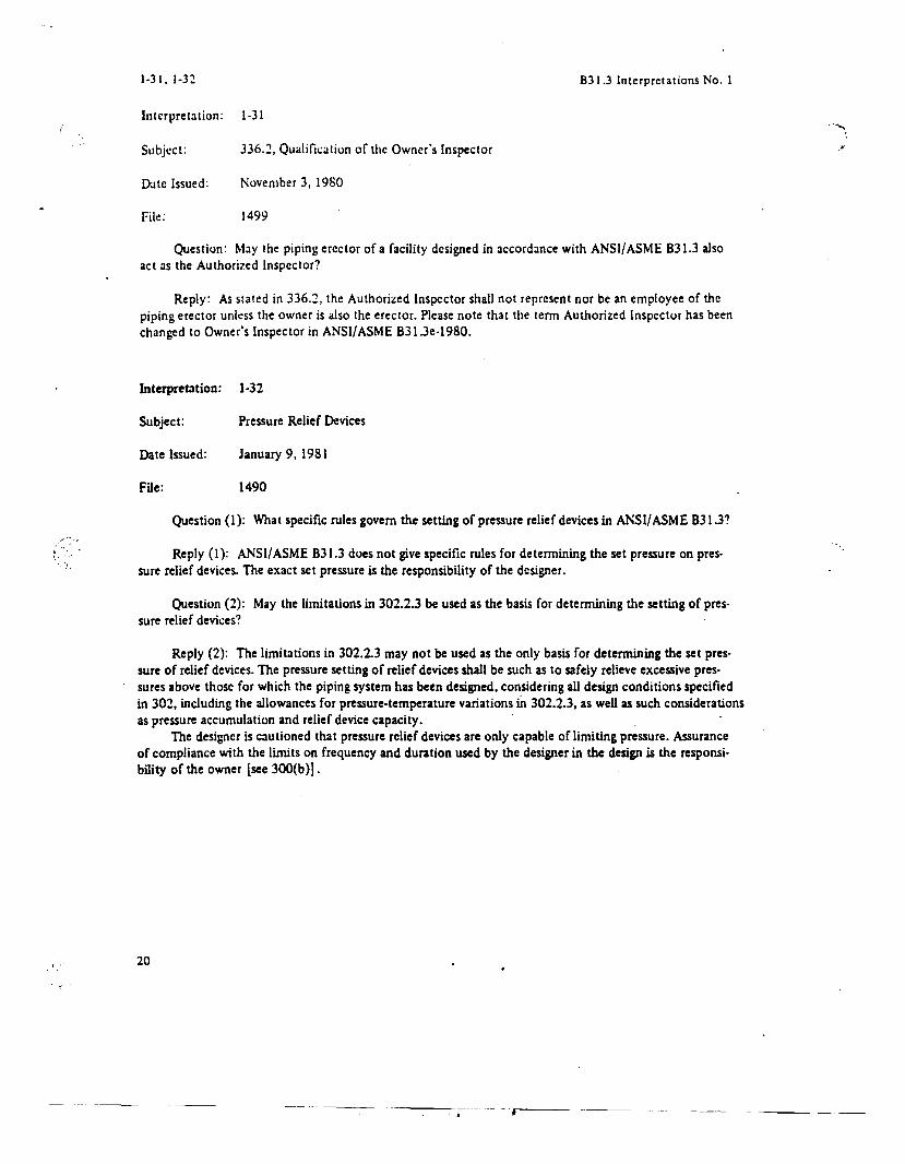
Interpretation: 1-31 .. ...."
Subject:
I)Jte Issued:
File:
336.1, Qualification of the Owner's Inspector
November 3, 1980
1499
.>
Question: May the piping erector ofa facility designed in accordance with ANSI/ASME 831.3 alsoact as the Authorized Inspector?
Reply: As stated in 336.1, the Authorized Inspector shall not represent nor be an employee of thepiping erector unless the owner is also the erector. Please note that the term Authorized Inspector has beenchanged to Owner's Inspector in ANSI!ASME 831.3e·1980.
Interpretation: 1·32
Subject: Pressure Relief Devices
Date Issued: January 9.1981
File: 1490
Question (l): What specific rules govern the setting of pressure relief devices in ANSI/ASME 831.3?
Reply (I): ANSI/ASME 831.3 does not give specific rules for determining the set pressure on pres·sure relief devices. The exact set pressure is the responsibility of the designer.
Question (2): May the limitations in 302.2.3 be used as the basis for determining the setting of pressure relief devices?
Reply (2): The limitations in 302.2.3 may not be used as the only basis for determining the set pressure of relief devices. The pressure setting of relief devices shall be such as to safely relieve excessive pres·sures above those for which the piping system has been designed, considering all design conditions specifiedin 302, including the allowances for pressure·temperature variations iit 302.2.3, as well as such considerationsas pressure accumulation and relief device capacity.
The designer is cautioned that pressure relief devices are only capable of limiting pressure. Assuranceof compliance with the limits on frequency and duration used by the designer in the design is the responsi·bility of the owner [see 300(b)] .
20
•

B31.3 Interpretations No.1
Interpretation: 1·33
Subject: 319.4.1, Requirements for Analysis
1-33,1-34
( '"...',""". '/
'<.,'
Date Issued:
File:
January 9,1981
1507
Question (1): 319.4.l(c) of ANSI B31.3-1976 lists an empirical equation that can be used to exemptpiping systems from the requirement fora formal analysis of adequate flexibility. The statement is madethat in order to apply Eq. 19 (Eq.16, 1980 Ed.), the system must be "of uniform size". Please provide aninterpretation on what is meant by "uniform size".
Reply (1): Uniform size refers to a piping system of a single nominal diameter and thickness.
Question (2): In a footnote, a warning is given listing additional criteria to be considered. Containedin the warning is a reference to "near straight sawtooth runs". Please provide an interpretation of what"near straight sawtooth runs" are.
Reply (2): Near straight sawtooth runs occur in piping systems containing more than one small U, L.or Z shaped expansion loop, or bends between two anchor points.
Question (3): Considering the limitations referenced, is it the opinion of the Committee that theformula is in general use?
Reply (3): The Committee cannot offer any specific information concerning the frequency or use ofthe formula; however, the Committee is aware that the formula is still used.
The reader is referred to a paper by A. R. C. Madel, "Piping Flexibility Analysis," published in theASME transactions, 1955, for additional information.
Interpretation: 1-34
Subject: Appendix D on Stress Intensification Factors
Date Issued: February 23,1981
File: 1470-1
Question: Is it the intent that the stress intensification factors shown in Appendix D of each reospective Code be applied for sustained and occasional loads as weD as for expansion loads?
Reply: Stress intensification factors (SIF's) listed in Appendix D of the various Code Sectionsare intended for design against fatigue failure and were to a large extent developed from cyclic bendingtests of piping components. Therefore, the application of the SIF for cyclic bending and torsion loads isappropriate. Sustained and occasional loads may not be cyclic loads; however, it is the intent of the variousCodes to provide adequate protection from component collapse. It has been shown that the SIF of 0.75;(but not less than 1.0) found in ANSI/ASMEB31.1 applied to sustained and occasional bending and torsionloads provides a conservative margin against component collapse.
21
t

(
1-35, 1-36
Interpretation: 1·35
B31.3 Interpretations No.1
.........
Subjcct:
Date Issued:
File:
Hydrostatic and Pneumatic Testing
March 6. 1981
1508
Question: If piping designed for external pressure is tested hydrostatically or pneumatically inaccordance with 337.4.3(a) or 337.4.4, is it necessary to use the ratio of the allowable stress at test temperature to the allowable stress at design temperature in establishing the test pressurc, as in Eq. 27 (nowEq. 24) of 337.4.I(b)?
Reply: No.
Interpretation: 1-36
Subject: 337.5.2, Alternative Test for Category 0 Fluid Service
Date Issued: March 6, 1981
File: 1509
Question (1): What pressure should be used for the preliminary check required in 337.5.2 if the operating pressure of the system does not exceed 25 psig?
Reply (1): It is the intent of 337.5.2 that the preliminary check be conducted at a pressure less thanthe operating pressure to minimize the consequences of gross leakage or failure dUring the test. The valueto be used shall be selected by the designer after consideration of such consequences.
Question (2): What test fluid does 337.5.2 require for the preliminary check?
Reply (2): 337.5.2 does not define the test fluid requirements for the preliminary check.
Question (3): May the preliminary check be waived if the operating pressure is less than 25 psig?
Reply (3): No.
Please note that the test may be conducted during or prior to initial operation.
22

B31.3 Interpretations No.1
Interpretation: 1-37
1-37,1-38
Subject: Use of Term, "Radius of allY Arc Sector of Approximately 45.deg." in 304.3.4(c)
Date Issued:
File:
April 24, 1981
1496
Question: In 304.3.4(c)(3), what is intended by the expression "radius of any alC sector of approxi·mately 4S deg."?
Reply: The approximate 45 deg. arc sector is specified as a practical necessity for establishing maxi·mum and minimum radii limits on a die controlled contour that may have a continuously varying radius ofcurvature. The current Edition of the Code does not address the limits of radii at any specific point on thesurface, although the intent of the Code is met if the radius of curvature is nowhere less than the specifiedminimum. The best fit radius to any 45 deg. arc shall be within the minimum and maxinlum radii limitsspecified in 304.3.4.
Interpretation: 1·38
Subject: Yield Strength Values for ASTM A 570 Gr. C
Date Issued: April 24, 1981
Question: Using the criteria of ANSI/ASME B31.3, what values of yield strength for ASTM A 570Gr..C are suitable for establishing allowable stresses for this material from -20°F to 750°F?
File: 1510
Reply: Suitable yield strength values for ASTM A 570 Gr. C from -20°F to 750°F are:
Temperature, eF-20 to 100
2003004005006006S0700750
Yield Strength, ksi33.030.129.328.326.724.424.023.823.1
Note that the yield strength does not govern in estabUshing allowable stresses in this temperature range.It should be noted also that the only pipe specification listed in Appendix A using ASTM A 570 material isA 134, which is limited to Category D Fluid Service (see 30S.2.l).
23 c

1·39. 1-40 B31.3 Interpretations No. I
Interpretation: 1·39
Subject:
Date Issued:
File:
331.3.6. Thickness Effect on Heat Treatment Requirements
April 24, 1981
1517
Question (1): In ANSI/ASME B31.3, is postweld heat treatment required for an NPS 2 or smallersocket or seal weld if the fitting is A 182·F5, the pipe is A 33S·PS, a 350°F preheat is used, and the mletweld size is less than Yo: in.?
Reply (I): No, if the provisions of 331.3.6(b) (2) are met.
Question (2): Same, except the fitting is A 182·Fsa?
Reply (2): Postweld heat treatment is required by 331.3.6(b) (2). Exceptions to this requirement arein 331.1.1 and 331.3.6(b) (3).
Question (3): In ANSI!ASME B31.3, is postweld heat treatment required for an NPS 2 or smallersocket or se~ weld if the fitting is A 182·Fs or A 182·Fsa, the pipe is A 33s·Ps, and the weld is made withmetal that is not air hardening?
Reply (3): No, provided the requirements of 331.3.6(b) (3) are met.
Interpretation: 140
Subject: Defmition of Category M Fluid Service in 300.2
Date Issued: April 24, 1981
File: 1518
Question: What constitutes "a very small quantity" in the defi~ition of Category M Fluid Service,in 300.21
Reply: "A very small quantity" is the amount determined by the owner to be significant in hisidentification of a Category M Fluid Service. See 300(b) (I).
24

B31.3 Interpretations No.1
Interpretation: 141
1-41,1-42,1-43
Subject:
Date Issued:
File:
Table 327.4.1A, Umitations on Imperfections in Welds
April 24, 1981
1522
Question: Arc different type imperfections as listed in Table 327.4.1A permitted in the same area, aslong as each specific imperfection is within its own respective limitation?
Reply: Yes.
Interpretation: 142
Subject: Joint Factors
Date Issued: May 22,1981
File: 1527
Question (1): Does ANSI/ASME B31.3 require the use ofa joint factor Ej other than 1.0 when estab·lishing SE values for calculating the required thickness (304.1) of seamless pipe containing a circumferentialweld(s)?
Reply (1): No.
Question (2): Why doesn't Table 302.3.4 list a joint factor for a circumferential or girth butt weld?
Reply (2): Table 302.3.4 does not list a joint factor for a circumferential or girth butt·weld becausenone of the design rules covered in ANSI/ASME B31.3 require the use of such a factor.
Interpretation: 143
Subject: 337.4.4, Pneumatic Testing
Date Issued: May 22.1981
File: 1531
Question: Should a temperature correction such as that given in Eq. 24 of 337.4.2 (Eq. 27 of the1976 Edition) be applied to a pneumatic pressure test in 337.4.4?
Reply: The requirement for a temperature correction does not apply to pneumatic pressure testingin 337.4.4.
25

,',
144, 145
Interpretation: 144
B31.3 Interpretations No.1
"
Subject:
Date Issued:
File:
Components and Material Manufactured to an Edition of a Standard or SpecificationWhich Has Been Superseded
May 29,1981
1526 (3)
Question: Dated component standards and materials specifications which are acceptable for use arelisted in Appendix K. Under what conditions is it permissible to use components and material manufacturedto a superseded or later edition of these standards and specifications?
Reply: Components and material manufactured to an edition of a standard or specification which hasbeen superseded in the ANSI/ASME B31.3 Code may be used in piping systems designed and constructed tothe edition of the Code in which they were listed.
Components and material manufactured to an edition of a standard or specification which has beensuperseded or has a later date than in the edition of ANSI/ASME B31.3 under which the piping system(s) isbeing designed and constructed shall be evaluated as an unlisted component (302.2.3) or unlisted material(323.1.1).
Interpretation: 145
Subject: 336.5 and M336.5, Type and Extent of Required Examination
Date Issued: July 21,1981
File: 1542
Question: 336.5.1 (b) requires that random radiography be used to examine the full length of at least5% of the circumferential butt welds in a piping installation. M336.5.l (b) increases the minimum to 20%and includes other types of welds. Referring only to circumferential butt welds, if 100% radiography is applied, may the user omit the visual examination of these welds which is required by 336.5.1 (a) andM336.5.1 (a), respectively?
Reply: No.
26
• 0·" ..
---------- ---~------,----- -~----------

B31.3 Interpretations No.1
Interpretation: 146
Subject: Stress Intensification Factors
1-46
Date Issued:
File:
August 7.1981
1537
(
Question: When applying the equations given in Appendix 0 for determining the stress intensifica·tion factor for a reinforced fabricated tee with a pad, what limits does the Code place on the width of thereinforcing pad?
Reply.: The Code does not place any limits on the width of reinforcing pad used other than those reoquired by 304.3 for pressure design.
The reader is referred to the transactions of the ASME Vol. 74, No.3, "Fatigue Tests of PipingComponents" by A. R. C. Mark! for a more complete discussion of the technical basis for the Code rules.
27
------ _ .._- -
(2... '.".:.'. -:
".",-
1-47
Interpretation: 1-47
B31.3 Interpretations No.1
Subject:
l)Jte IsslIed:
File:
1331.3 and 1331.4, Comparison orCodes
Septcmber 4, 1981
1538
Question: Why cannot the two piping Code Sections B31.3 and 831.4 be combined into a singleCode Section?
Reply: It is the opiniun of the BJ 1 Cummit tce that it is appropriate to continue publishing ANSI!ASME 1331.3 and ANSI/ASME B31.4 as separate Cude Sectiuns for the folloWing reasons.
(a) Estahlislu:d Practice. Publication of separate Code Sections began in 1952. In 1955, the B31Committee decided, after review of pertinent factors, that other industry Sections should also be publishedseparately. The last edition of a combined Code for Pressure Piping, ASA B31.1·1955, appeared that sameyear.
(b) Basis for Decisions. Questions of combining Code Sections, as well as developing new Sec·tions, have been rais~d periodically during the past 25 years and, in fact, decisions to combine two Sectionshave been made in two instances. Decisions to merge, or to develop separate Se..:tions, have been based onsimilarities and differences in the folloWing factors:
(1) Services - fluids handled, range of pressure and temperature, etc.(2) Environments - surroundings which may impact on piping safety, or which may be affected
by possible piping failure.(3) Application - how the Code is used; actual or potential regulatory jurisdictions.
These factors, where they differ substantially as in the case of piping for refineries and chemicalplants versus piping for cross-country oil transportation, account for crucial differences in philosophy reolating to design. construction, operation, and maintenance of piping - which in turn necessita te separateSections.
(c) Diffm:llL'cs vs. Similarities. Similarities among different Code Sections are natural and encouragedbecause of similarities in the basic subject matter. Several technical Committees are maintained by the B31Committee to exploit opportunities for common practice among all Code Sections. But these similarities donot warrant merging one Section with another where basic differences in services, environment, and applica·tion exist.
(d) Specific Differences. A few of the major differences between B31.3 and B31.4that arise frombasic differences outlined above arc listed here. There are many others..
(1) Allowable Stress Basis. The more extensive and complex criteria in B31.3 are necessitated bythe extreme range of temperatures and material of construction.
(2) Unlisted MateriJlls and Cumpcments. nlese are not permitted under B31.4 because servicesare of limited diversity. They arc permitted, with rules for qualifying them, in B31.3 because unanticipatedservice can be expected to require them. .
(3) Umi/atiuns un Components and Joints. These are expressed as straightforward rules in 831.4.In B31.3 they require complex guidelines (e.g.• the safeguarding and severe cyclic conditions concepts) be·cause of the diversity of services and environments. .
(4) Operation and Maimelw"cc. nlese are not dealt with in B31.3 because the complexity ofactivities is too great for effective codilication (e.g., corrosion can take so many forms and result from somany sources that the designer must rely on expertise not found in the Cllde). In 831.4 the fruits of manyyears of experience are summed up in useful rules (e.g., for corrosion protection and monitoring) which alsoaid in protecting the public.
28

B3I.3 Interpretations No. 1
Interpretation: 148
Subject: Carbon Sleel Pipe
148,149,1'50
C,,"":. ~',
<~~:., ,
Date Issued:
File:
September 8, 198 I
1549
Question (1): For carbon steel pipe made from plate (such as ASTM A671) for service below -20°F, isnormalizing the plale acceptable or does the pipe require normalizing?
Reply (I): Either approach is acceptable as long as the finished product meets the impact requirements of the Code.
Question (2): What are the allowable B31.3 stresses for ASTM A671 Classes 30, 31, and 32?
Reply (2): The allowable stresses for unlisted materials may be determined in accordance with323.1.1.
Interpretation: 149
Subject: 321, Design of Pipe Supporting Elements
Date Issued: September 8, 1981
File: 1552
(
Question: Does 321.1.4(d) permit plastic materials approved for pressure piping to be used as pipesupport elements in tension at pipe temperatures above ambient?
Reply: Yes, provided the other reqUirements of 321.1 have been satisfied.
Interpretation: I-SO
Subject: Loads Due to Pressure Surges
Date Issued: September 8. 1981
PUe: ISS3
Question: How shall longitudinal piping stresses due to unbalanced loads from pressure surges whichresult in anchor displacements be evaluated in ANSI/ASME B31.3?
Reply: Loads due to pressure surges are considered as primary loads. and longitudinal stress limitsmust comply with 302.3.3(c) for sustained loads or 302.3.6 for occasional loads. Pressure-temperaturelimits of 302.2 must also be met.
29

1·5 I, 1·52 B31.3 Interpretations No.1
Intcrprcbtioll: 1-S 1(".
Subject:
Date Issued:
File:
Use of Aluminum Flanges
October 19. 1981
1554
..• j
Question: Will ASME B31 reinstate ANSI BI6.31, "Non·Ferrous Pipe Flanges 150,300,600,900,1500 and 2000 lb" that has been dropped from ANSI/ASME B31.3·1980 Edition, Addenda ANSI/ASMEB31.3a-198I ?
Reply: Since the American National Standards Institute has withdrawn ANSI B16.3 I, the Committee considers it inappropriate to reference it. Please refer to 304.7.2 for qualifying unlisted aluminumflanges.
Interpretation: I-52
Subject: B31.1 and B31.3, Synfuel Plant Piping
Date Issued: October 27, 1981
File: 1541
Question: What section of the ASME Code for Pressure Piping, B31, may be used for materials, design, fabrication, assembly, erection, examination, inspection, and test of piping within coal based syn fuelsplants for the production of electric power and/or industrial steam?
Reply: ANSI/ASME B31.1 applies to piping associated with power boilers and subject to ASMEBoiler and Pressure Vessel Code Section 1inspection and stamping. (See B31.1, 300.1.3 (b) and Fig.300.1.1.)
Either ANSI/ASME B31.1 or B31.3 is applicable to other piping associated with the production ordistribution of industrial steam or production of electric power. (See B31.3, Fig. 300.1.1.)
ANSI/ASME B31.3 applies to all other piping.
30

B31.3 Interpretations No. I
Interpretation: I-53
Subject: Ddinition of "Substantially Free of Buckles"
I-53, I-54
Date Issued:
File:
February 10, 1982
148SR
Question: Since ANSI/ASME B31.3 does not specifically define the phrase "substantially free ofbuckles," is it intended that the definition of "substantially," given in Webster's New Collegiate Dictionary,be applicable?
Reply: It is appropriate to use a recognized English language dictionary for each of the words in aphrase, in the absence of any specific definition in the Code.
Interpretation: 1·54
Subject: Definition of "d" in 304. l.l (b)
Date Issued: February 18,1982
FUe: 1566
Question: In accordance with 304. l.l (b), what is the correct definition ofd, inside diameter of pipe,given in equation form?
Reply: The correct dermition ofd for pressure design is given by the following equation:
d -D- 2(T- c)
where D and care dermed in 304.1.1 and T = pipe wall thickness, measured or minimum per purchasespecification (see Appendix 1).
31
,.

}-55
Interpretation: I-55
Subject: 304.3.4 and Appendix D
B31.3 Interpretations No. }
[}Jte Issued:
File:
February 19, 1982
1567
Question (1): Maya "drawn tee" be considered as an extruded outlet header in accordance with304.3.4?
Reply (I): Yes, provided that it is extruded using a die or dies to control the radii of the extrusionand that all of the limits on geometry required by 304.3.4 are met.
Question (2): Are the stress intensification factors given in Appendix 0 for welding tees valid forfabricated tees and/or for tees formed by an extrusion process?
Reply (2): The stress intensification factors given in Appendix 0 for welding tees are not valid forfabricated tees employing intersection welds. Stress intensification factors for fabricated tees are givenseparately in Appendix 0 in the description column.
The stress intensification factors for welding tees formed by an extrusion process are given in Appen·dix 0 both for tees in accordance with ANSI B16.9, with the geometry limits specified, and for extrudedwelding tees with other geometry limits.
Question (3): Is the flexibility characteristic h specified in Appendix 0 for an extruded welding teevalid only within the geometry limits for, given in 304.3.4(c)?
Reply (3): Yes. Refer to Note 2 in Appendix D.
Question (4): When the geometry limits specified for the components listed in Appendix D are notmet, what equations should be used in calculating the respective flexibility characteristic h?
Reply (4): ANSl/AsME B31.3 does not specifically address the requirements for flexibility charac·teristic h outside the geometry limits specified in Appendix D. Refer to 319.3.6 for components not covered
. in Appendix D.
Question (5): Are the geometry limitations specified for components listed in Appendix D intendedto be mandatory for manufacturing such components?
Reply (5): No; unless specifically required elsewhere in ANSl/ASME B31.3, the geometry limitationsgiven in Appendix 0 are intended only to provide limits on the specific applicability of the equations forflexibility characteristic h.
Question (6): Can the limitations on,x required in 304.3.4(c) and Appendix D both be met in allinstances?
Reply (6): In certain instances, for large diameter welding tees for ANSI BI6.9. all of th~ geometrylimits specified for,x in Appendix D and in 304.3.4(c) cannot be met, in which case the flexibility characteristic II specified for B16.9 welding tees is not directly applicable. Appendix 0 also provides an equation for flexibility characteristic h for extruded welding tees with other than B16.9 geometry limitations.Refer also to 319.3.6 for components not covered in Appendix D.
32
~ ,!
.'

B31.3 Interpretations No. I
Interpreta tion: 1·56
Subject: Appendix D, Flexibility and Stress Intensification Factors
1·56
Date Issued:
File:
February 22,1982
1443
Question (1): What is the basis for the formulas for stress intensification factors and flexibility f3ctorsgiven in Appendix D?
Reply (J): Basic background material for derivations of formulas for flexibility characteristics can befound in the following:
(0) "Fatigue Tests of Welding Elbows and Comparable Double-Mitre Bends," by A. R. C. Markl,Trans. ASME Vol. 69, n 8, 1947, pp. 869·879.
(b) "Fatigue Tests on Flanged Assemblies," by A. R. C. Markl and H. H. George, Trans. ASMEVol. 72,1950, pp. 77-87.
(c) "Fatigue Tests of Piping Components:' by A. R. C. Markl, Trans. ASME Vol. 74, 1952,pp.287.303.
(d) "Piping Flexibility Analysis," by A. R. C. Markl, Trans. ASME Vol. 77,1955, pp. 127·149.(e) "-Effects of Internal Pressure on Flexibility and Stress·Intensification Factors of Curved Pipe
or Welding Elbows," E. C. Rodabaugh and H. H. George, Trans. ASME Vol. 79, 1957.if) "Comparisons of Test Data with Code Methods for Fatigue Evaluation," by E. C. Rodabaugh
and S. E. Moore, Phase Report No. 115·10, ORNL·TM·3520, Nov. 1971.
Question (2): What is the effect of relative branch to run diameter on the flexibility characteristic hin Appendix D?
Reply (2): The relative effect of branch diameter to run diameter on flexibility characteristic h forbranch outlets is being investigated at the present time. When properly substantiated design criteria areavailable, they will be considered for inclusion in the Code.
Question (3): Is f shown in Appendix D for extruded welding tees the nominal wall thickness ofthe fitting or the matching pipe?
Reply (3): The T to be used is the wall thickness of the matching pipe.
Question (4): What is the effect of external crotch radius,x and crotch wall thickness Tc on flexibil·ity characteristic h or extruded outlets?
Reply (4): The effect of crotch radius,x on flexibility characteristic h for extruded welding teeswithin specified thickness limits is given in Appendix D. From a practical standpoint both the externalradius of curvature 'x and the crotch wall thickness Tc have influence on the flexibility characteristic h.The formulated relationship has not been developed at the present time.
33
e····l).....;~' .. ,'. "~"
I... \. .'
c:

I-57, I-58
Interpretation: 1·57
831.3 Interpretations No.1
, . -~'.
Subject:
Date Issued:
File:
304.1.2, Straight Pipe Under Internal Pressure
February 22, 1982
1559
Question (1): In accordance with 304.1.2, may the Lame Eq. (3c) be used instead ofEq. (3a) for theinternal pressure design of straight pipe?
Reply (1): Yes, Eqs. (3a), (3b), and (3c) are all permissible."
Question (2): When the pipe wall thickness t is equal to or greater than 0.385, may the Lame theorybe used for calculating the stresses due to internal pressure?
Reply (2): Yes, the Lame theory may be used for the determination of elastic pressure stresses; how·ever, in the pressure design of piping components, other factors need to be considered such as those listedin 304.1.2(b).
A discussion concerning the bursting strength of thick walled cylinders is contained in the ASMEpublication, "Pressure Vessels and Piping: Design and Analysis., A Decade of Progress," B. F. Langer Com·memorative Volume, Vol. One, 1972.
Interpretation: I-58. ",
Subject: Note 2 of Appendix A J.. "
Date Issued: February 12, 1982
File: 1568
Question: Why does Note 2 of Appendix A specify a temperature of 800°F relative to the onset of. graphitization rather than 775°F as in ANSI/ASME B31.1 ?
Reply: Since the disassociation of the metastable iron carbide to graphite and iron is influenced bymany factors in addition to temperature (including time of exposure), it is difficult to be very precise inspecifying a temperature above which prolonged exposure will cause graphitization. The Committee con·siders the value of 800°F to be reasonable.
34
I

831.3 Interpretations No. I
Interprctation: I-59
Subject: 331.3.6, Thickness Effect on Heat Treatment Requirements
1-59,1-60
Date Issued:
File:
May 4,1982
1577
Question: 331.3 .6(a) of ANSI/ASME 831.3·1980 gives formulas for calculating thickness of variousbranch welds to determine if the weld requires heat treatment. For detail (I) of Fig. 327.4.40, the thicknessis given as Tb + te. The value of te is defined in 327 .4.4(b) as "the smaller of 0.7 Tb or Y.a in." For most, thenIlet size te is usually larger than y~ in. What value is reqUired to be used for te when determining heat treatment requirements?
Reply: 327.4.4(b) of ANSI/ASME 831.3-1980 states, "Welds shall be calculated in accordance with304.3.3 but shall not be leSs than the sizes shown in Fig. 327.4.40." The value for te to be used is thegreater of the minimum required in 327.4.4(b) (the smaller of 0.7 Tb or Y.a in.) or the size calculated for-thedesign.
Interpretation: 1-60
Subject: 336.5.1, Examination Normally Required
Date Issued: June 9,1982
File: 1569 ~1'.;
'. " '.'.....:-:,;.1""
Question: 336.5.1(b) of ANSI/ASME 831.3-1980 Edition requires a minimum of 5% of circumferential butt welds to be examined fully by random radiography ~n accordance with 336.4.5 or by ultrasonicexamination in accordance with 336.4.6 when piping is intended for service at temperatures above 366°F(l86°C) or gage pressure above 150 psi (1030 \cPa). If the fluid is toxic or flammable and exceeds neither150 psig nor 366°F service, does the 5% minimum examination apply?
Reply: The 1981 Addenda, ANSI/ASME B31.3a-1981, requires the 5% minimum examination if thefluid is toxic or flammable without regard to the pressure or temperature. Prior to issuance of the aboveAddenda, the 5% minimum examination did not apply. Also, please note that if specified in the engineeringdesign. in-process examination may be substituted on a weld-for-weld basis for the radiographic or ultrasoniceXJrtlination.
3S
._-- ---

c- •...,.- .•t ' .\~.
1-61
Interpretation: 1·61
Subject: 337.4.1, Hydrostatic Testing of Internally Pressured Piping
B31.3 Interpretations No.1
Date Issued:
File:
June9,l982
1576
Question (l): 337.4.1 (c) allows the hydrostatic test pressure to be reduced to the maximum pressurethat will not exceed the yield strength at test temperature. Does the Code require a weld joint qu:di'ty factorto be applied when calculating this maximum pressure?
Reply (1): No.
Question (2): Is this considered safe?
Reply (2): Yes, when all applicable requirements of the Code have been fulfilled; but no single reoquirement can be considered as the sole criterion for safety.
36

B31.3 Interpretations No. 1
Interpretation: 1-62
Subject: 336.5, Types and Extent of Required Examinations
1-62
(S" '.~. ....•. '.~, ," ":.. ;-", .
Date Issued:
File:
June 9,1982
1578
Question (1): The third sentence of 336.5 states, "when the required examination of a spot orrandom type reveals a defect requiring repair, two additional examinations of the same kind of item (if of aweld, others by the same welder or welding operation)."
Is it the intent of the Code that "same kind" encompass all of the following?(0) same type of base material;(b) same type of weldment;(c) same size of butt weld;(d) same method of welding operation.
Reply (1): No. This is a general statement applying to all spot and random examinations, Le., it isnot limited to welds. "same kind" examples are supports, threaded joints, bolted joints, alignment, coldspring, and welds. With respect to welds, the Code is not specific as to what criteria determine "same kind"except for the same welder or welding operator, but leaves such factors as base material, welding procedure,size of pipe, etc., to the requirements of the engineering design.
Question (2): Please refer to the progressive examination delineated in 336.5. For 5% radiography, atthe point of original examination, a 5% sampling has been represented (1 out of 20). Should that radiographfan to meet specification, two additional examinations are required, which represents a 15% (3 out of 20)sampling.
(0) If any of the second group faUs to meet Code, is it mandatory, as the Code implies, thatfurther examinations are required? Is the alternative available whereby all welds of that given group of 20may be totally repaired without subsequent radiographs?
(b) If any of the third group of radiographed welds fails to meet Code, does one progress to afourth group?
Reply (2):(0) No to both questions. The following options are available.
(1) Replace all items in the group. Examinations performed on items which are subsequentlyreplaced may not be counted as contributing toward the required percent random examination.
(2) Continue progressive examination, repair and reradiograph all defective welds until theyare acceptable. Only the first weld in the group may be counted toward the required percent.
(3) Repair and radiograph all welds in the group until all are acceptable. Only the fust weldin the group may be counted toward the required percent.
(b) No. At this point in the progression. aU welds in the group (20) shall be replaced or repairedand radiographed until acceptable.
Question (3): When a weld representing the 5% random radiography required by 336.5.1 (b) is de·fective, 336.5 requires radiographic examination of two additional welds by the same welder or weldingoperator and so on.
When a weld in the third group of the progression is found defective, the Code states, "all comparableitems may be replaced or they shall be fuUy examined and repaired to meet applicable quality requirements."
37

1-62,1-63,1-64 B31.3 Interpretations No.1
' .. ,.(0) If the welder was terminated after welding a total of II wclJs. docs replacement of the 11
welds or repair and examination of the II welds until the)' are acceptable terminate the proglcssion?(b) Is this c.;hanged if the total was 31 welds and the weld representing the first .20 welds was
found acceptable?
Reply (3):(0) Yes.(b) No. Only the group of II weld~ is required to be replaced or repaired and examined until
acceptable, Le., finding a defect in one group does not affect the status of another group.
Interpretation: 1-63
Subject: 337.4.2, Hydrostatic Testing Piping With Vessels as a System
Date Issued: June 9,1982
File: 1579
Question (l): For calculating the hydrostatic test pressure, 337 .4.2(b) conditionally allows a factorof 1.15 to be substituted for the 1.5 factor in Formula (24) [337 .4.1(b)}. Is this considered safe for subsequent operation?
Reply (1): Yes, if the owner has authorized the use of this conditional clause.
Question (2): If so, why can't one use 1.1 5 for all pressure tests?
Reply (2): The factor of 1.5 is required where feasible. The lower factor represents the Committee'sbest judgment for the special case of integrated equipment and piping which cannot be readily isolated for aseparate test. Also, the Owner must approve its use for each specific case.
Interpretation: 1-64
Subject: 336.5, Type and Extent of Required Examination
Date Issued: June 9,1982
File: 1580
Question: For PoNos. 3,4, and 5 materials, does radiographic examination performed before heattreatment satisfy the ANSIIASME 831.3 Code requirements?
Reply: No. 336.5 requires the examination to be performed after heat treatment.
38
.,-~
I,

B31.3 Interpretations No.1
Interpretation: 1-65
1-65,1-66
Subject:
Date Issued:
File:
Impact Testing
June 9,1982
1587
Question (J): Under ANSI!ASME 831.3 can austenitic stainless steel having OJ I::Hbon content of0.10% and below (including "H" grades) be used at -lOO°F without impact testing?
Reply (1): Yes.
Question (2): Is impact testing required for deposited filler metal of production welds, welded to aqualified welding procedure with nIler metal impact tested at -300°F?
Reply (2): No. See Note I, Table 323.2.2.
Question (3): Is heat treatment for austenitic stainless steel reqUired after welding?
Reply (3): No.
Interpretation: 1-66
Subject:
Date Issued:
FDe:
327.s, Qualification for Welding
June 9,1982
1588
(
Question: If a procedure for the GTAW or SMAW welding process is qualified in accordance with therequirements of 327.5 and the welder is qualified in both the uphill and downhill position, is it acceptableto the Code for the production welds to be made in either the uphill or downhill position?
Reply: Yes. Please note that when the Supplementary Essential Variables - Notch Toughness of theASME BPV Code Section IX are applicable, the progression for welding the qualification test is reqUired tobe uphill.
39
--------

1-67. 1-68
Interpretation: 1·67
B31.3 Interpretations No.1
Subject:
Date Issued:
File:
A304.5. Pressure Design of Flanges
June 9. 1982
1589
Question: In accordance with A304.5.1(d), what is the correct Appendix in Section VIII. Division 1of the ASME BPV Code for the design of full face gaskets?
Reply: The correct Appendix in Section VIII , Divison 1 of the 1980 Edition of the ASM E BPV Codefor the design of full face gaskets is Appendix Y. Section Vlll recently reorganized portions of Division 1and the existing reference in Addenda (a) of B31.3 is to an earlier edition of the ASME BPV Code.
Any revisions to tltis section of A."lSI/ASME B31.3 will appear in future Addenda.
Interpretation: 1-68
Subject: High Pressure
Date Issued: June 9,1982
FUe: 1592
Question: What calculation method shall be used for the pressure design of pipe with t :> D/6, orP/SE> 0.3857
Reply: The Code does not have a specific design procedure for designs in the high pressure range atthis time.
The ASME B31.3 Subgroup on High Pressure Piping is a Committee currently working on specificdesign rules for the High Pressure range. These rules, when approved, will appear in a future Addenda ofANSI/ASME B31.3. The reader is referred to the following publications for a discussion of pressure designin the high pressure range:
(a) Welding Research Council Bulletin #95/AprU 1969, "PVRC Interpretive Report of PressureVessel Research: Section I Design Considerations," B. F. Langer
(b) ASME Paper No. S5· PET· I, "Yield and Bursting Characteristics of Heavy-Wall Cylinders,"J. H. Faupel
40
.."""\
.•. J'

B31.3 Interpretations No. I 1-69,1-70
Interpretation: 1-69
Subject: Table 331.3.1, Requirements for Heat TreatmentC
:--. 'I":":' ',",-:i~;.,'
Date Issued: June 9,1982
File: 1593
Question (I): Docs ANSI/ASME B31 .3 require specific heating rates when performing heat treatment?
Reply (1): No.
Question (2): Does the cooling rate at the bottom of Table 331.3.1 apply only to P-No. llA, GroupNo.1 materials?
Reply (2): Yes.
Interpretation: 1·70
Subject: 304, Pressure Design
Date Issued: June 9,1982
Fue: 1594
Question (l): What is the correct value ofD for calculating the required pressure design thickness ofan externally reinforced extruded header by Eq. (3a)1
Reply (1): The correct value D is the outside diameter of the header (see Fig. 304.3.4). The Committee will give consideration to future revision of these diagrams.
Question (2): Is it permissible to calculate the required pressure design thickness of an externailyreinforced extruded header on the basis of the inside diameter?
Reply (2): Yes. The following equation is equivalent to Eq: (3a) for an externally reinforced extrudedheader using inside diameter d:
P(d+ 2c)t -= 2 (SE - P (l - Y)]
where nomenclature is as dermed in 304.1.1 of ANSI/ASME B31.3a·1981.
41
C:~--':"-
. ,""; ••- 1\,'
.-
~--~-----

-",.<•.•.; '. "I
1-71, )-72 B31.3 Interpretations No. I
Interpretation: 1-7 J
Subject: Appendix D, Flexibility and Stress Intensification Factors
Date Issued:
File:
July 13,1982
1597
r·I
---------
" .
Question: Are the stress intensification factors for tees given in Appendix D applicable to both thebranch as well as the run or header?
Reply: Yes, the stress intensification factors for tees given in Appendix D are applicable to both thebranch and run or header. The computation of stress using those stress intensification factors must be basedon the appropriate section modulus. Equation 21 gives the appropriate formula for the "effective sectionmodulus of the bran'ch:,f ., '.""'"
Interpretation: 1-72
Subject: 337, Pressure Tests
Date Issued: July 16,1982
File: 1609
Question: What are the requirements for pressure testing of discharge piping in ANSI!ASME B31.3?
Reply: ANSI/ASME B31.3 requires discharge piping to be tested in accordance with 337 unless excluded from Code coverage by 300.1.3.
42
"--

I ..... ,;:.' •
B31.J Interpretations No. 1
JI"erpret3tion: 1·73
subject: Category M Fluid Service
Date Issued: September 8.1982
1-73.1·74
File: 1596
Question: Is a "Category M Fluid" in ANSI!ASME B31.3 the same as a "lethal substance" in theASME BPV Code Section VIII?
Reply: The Committee points out that the term used in ANSI!ASME B31.3 is "Category M FluidService," not "Category M Fluid." This distinction is very important in understanding the intent of ANSI!ASME B31.3. "Fluid Service" is much broader in concept in that it encompasses the complete handling andcontrol of the fluid. It takes into consideration not only the fluid properties (such as flammability, toxicity,.etc.) but also the service conditions.(such as pressure, temperature, quantity ,location, etc.) as they affectan aspects of the piping system.
Finally, in developing "Category M Fluid Service," it was not the intent of ANSI!ASME B31.3 toparallel the "lethal substance" reference in the ASME BPV Code Section VIII. Division 1.
Interpretation: 1-74
Subject: 327.4.4, Welded Branch COMections
Date Issued:
File:
October 26,1982
1598
Question (1): For branch connections, 327.4.4(c) requires a cover fillet weld with a minimum throatdimension of tc. Figure 327.4.40 shows te in the longitudinal plane of the header (run) which bisects thebranch. When the branch and header (run) are the same nominal pipe size, (a) what is the required coverrillet at the transverse plane of the header (run) which bisects the branch; and (b) in those branch bisectingplanes moving from the transverse of the header (run) toward the longitudinal of the header (run)?
Reply (1):(a) A rillet weld is not applicable as the weld, in that plane, is a groove butt joint.(b) The Code does not define rillet weld size at this location of the joint, but weld geometry
should provide a smooth transition between the weld and the groove weld with added fillet weld.
Question (2): What is the required cover rillet weld at the longitudinal plane of the header (ron)which bisects the branch when beta [see 304.3.3 (a)] is less than 90 deg. (angular branch)?
Reply (2): The Code does not dermc nllet weld size reqUired for this joint configuration, but weldgeometry should provide a smooth transition between the branch and header (run) surfaces.
43
...---- .._.
L' ,
1"',,.:.:,,';
", . ~ . ...
. ,r ,., ~

1·75. 1·76 B31.3 Interpretations No.1
Interpretation: 1·75
Subject:
Date Issued:
File:
Definition of til in 304.3.4(d)
October 26. 1982
1613
Question: In 304.3.4(d). is th the nominal wall thickness?
Reply: No. th is the pressure design thickness of the header. Refer to Appendix J for nomenclatureand 304.3.3(a) for determination of th for reinforcement calculation.
Interpretation: 1·76
SUbject: Impact Testing
Date Issued: October 26.1982
Fue: 1615
Question (1):(a) Does ANSI B31.3-1976 including Addenda through ANS1/ASME B31 .3e·1980 require the
fabricator and assembler to perform impact testing of the deposited weld metal and heat affected zone inaccordance with 323.3 when the material is either carbon steel. low alloy steel, intermediate alloy steel, orhigh alloy (ferritic or martensitic) steel, and the Engineering Design specifies a design temperature below-20°F (-29°C)?
(b) Note 2 of Table 323.2.2 of ANSI B31.3·1976 including Addenda through ANSI/ASMEB31.3e·1980 allows an exclusion from impact testing. For one to take advantage of this exclusion, is permission required from the Design Engineer?
Reply (1):(a) Yes.(b) Yes, the design engineer is responsible for evaluating the piping system and authorizing the
exclusion. . .
Question (2): Does ANSI B31.3·1976 including Addenda throughANSI/ASME B31.3e·1980 requirethe fabricator and assembler to perform impact testing of the deposited weld metal in accordance with323.3 when the material is austenitic stainless steel and the Engineering Design specifies a design tempera·ture below _20°F (_29°C)?
Reply (2): Yes.
Question (3): Is specification of a design temperature below -20°F (-29°C) for the above materialssufficient [see 327.s.1(d)] to require the impact testing of weld specimens in qualifying weld procedurespecifications? .
Reply (3): Yes.

B31.3 Interpretations No. I
Interpretation: J.77
Subject: Note 30 of Appendix A
1-77.1-78
C·'"'."
~' ...~, -•...
Date Issued:
File:
October 26, 1982
1616
(
Question: Appendix A, Note 30 specifies a reduced tensile strength (70.0 ksi rather than 75.0 ksi)for pipe of NPS 8 and larger with wall thickness of schedule 140 or heavier. Is this Note correctly referencedin the stress tables for pipe made in conformance to ASTM A 312 and A 403 specifications?
Reply: No. These references are erroneous and will be corrected in future Addenda.
Interpretation: 1-78
Subject: Use of API 5L Grades A and B Double Submerged Arc Welded Pipe
Date Issued: November 23, 1982
FDe: 1623
Question (1): Is API 5L, Grades A and B double submerged arc welded (DSAW) pipe acceptableunder ANSI/ASME B31.3?
Reply (1): Yes.
Question (2):(a) Does this material fall under the "Electrical Fusion Welded Pipe" (straight seam) classification?(b) In future Editions of ANSI/ASME B31.3, will API SL DSAW pipe be formally listed with a
DSAWclassification and listing of allowable stresses?
Reply (2):(a) Yes.(b) There are no plans to include a separate DSAW classification. The reader is referred to Table
302.3.4, Nos. 3b and 4b, for additional Ej weld joint quality factors which can apply to this pipe specifica·tion.
Question (3):(a) For API SL DSAW pipe with wall thickness greater than ~ in., does the manufacturer's weld
require postweld heat treatment to meet the requirements of ANSI/ASM'E B31.3?(b) Can hardness testing be substituted for stress relieving?
Reply (3):(a) Yes, except as provided for in 331.1.1.(b) No.
45