
120324amwaybusinessopportunitypresentation 13326809046049-phpapp02-120325081048-phpapp02
Upload
kahtan-adnanCategory
view
253download
1
Gas Transmission and Distribution Piping Systems
ASME Code for Pressure Piping, B31
A N A M E R I C A N N A T I O N A L S T A N D A R D
ASME B31.8-2012(Revision of ASME B31.8-2010)
Copyright ASME International Provided by IHS under license with ASME No reproduction or networking permitted without license from IHS

Copyright ASME International Provided by IHS under license with ASME No reproduction or networking permitted without license from IHS

ASME B31.8-2012(Revision of ASME B31.8-2010)
Gas Transmission andDistribution PipingSystems
ASME Code for Pressure Piping, B31
A N A M E R I C A N N A T I O N A L S T A N D A R D
Three Park Avenue • New York, NY • 10016 USA
Copyright ASME International Provided by IHS under license with ASME No reproduction or networking permitted without license from IHS

Date of Issuance: January 4, 2013
The next edition of this Code is scheduled for publication in 2014. This Code will become effective6 months after the Date of Issuance.
ASME issues written replies to inquiries concerning interpretations of technical aspects of this Code.Interpretations, Code Cases, and errata are published on the ASME Web site under the CommitteePages at http://cstools.asme.org/ as they are issued.
Errata to codes and standards may be posted on the ASME Web site under the Committee Pages toprovide corrections to incorrectly published items, or to correct typographical or grammatical errorsin codes and standards. Such errata shall be used on the date posted.
The Committee Pages can be found at http://cstools.asme.org/. There is an option available toautomatically receive an e-mail notification when errata are posted to a particular code or standard.This option can be found on the appropriate Committee Page after selecting “Errata” in the “PublicationInformation” section.
ASME is the registered trademark of The American Society of Mechanical Engineers.
This code or standard was developed under procedures accredited as meeting the criteria for American NationalStandards. The Standards Committee that approved the code or standard was balanced to assure that individuals fromcompetent and concerned interests have had an opportunity to participate. The proposed code or standard was madeavailable for public review and comment that provides an opportunity for additional public input from industry, academia,regulatory agencies, and the public-at-large.ASME does not “approve,” “rate,” or “endorse” any item, construction, proprietary device, or activity.ASME does not take any position with respect to the validity of any patent rights asserted in connection with any
items mentioned in this document, and does not undertake to insure anyone utilizing a standard against liability forinfringement of any applicable letters patent, nor assumes any such liability. Users of a code or standard are expresslyadvised that determination of the validity of any such patent rights, and the risk of infringement of such rights, isentirely their own responsibility.Participation by federal agency representative(s) or person(s) affiliated with industry is not to be interpreted as
government or industry endorsement of this code or standard.ASME accepts responsibility for only those interpretations of this document issued in accordance with the established
ASME procedures and policies, which precludes the issuance of interpretations by individuals.
No part of this document may be reproduced in any form,in an electronic retrieval system or otherwise,
without the prior written permission of the publisher.
The American Society of Mechanical EngineersThree Park Avenue, New York, NY 10016-5990
Copyright © 2013 byTHE AMERICAN SOCIETY OF MECHANICAL ENGINEERS
All rights reservedPrinted in U.S.A.
Copyright ASME International Provided by IHS under license with ASME No reproduction or networking permitted without license from IHS

CONTENTS
Foreword . . . . . . . . . . . . . . . . . . . . . . . . . . . . . . . . . . . . . . . . . . . . . . . . . . . . . . . . . . . . . . . . . . . . . . . . . . . . . . viiiCommittee Roster . . . . . . . . . . . . . . . . . . . . . . . . . . . . . . . . . . . . . . . . . . . . . . . . . . . . . . . . . . . . . . . . . . . . . xIntroduction . . . . . . . . . . . . . . . . . . . . . . . . . . . . . . . . . . . . . . . . . . . . . . . . . . . . . . . . . . . . . . . . . . . . . . . . . . . xivSummary of Changes . . . . . . . . . . . . . . . . . . . . . . . . . . . . . . . . . . . . . . . . . . . . . . . . . . . . . . . . . . . . . . . . . . xvi
General Provisions and Definitions801 General . . . . . . . . . . . . . . . . . . . . . . . . . . . . . . . . . . . . . . . . . . . . . . . . . 1802 Scope and Intent . . . . . . . . . . . . . . . . . . . . . . . . . . . . . . . . . . . . . . . . 1803 Piping Systems Definitions . . . . . . . . . . . . . . . . . . . . . . . . . . . . . . 2804 Piping Systems Component Definitions . . . . . . . . . . . . . . . . . . 4805 Design, Fabrication, Operation, and Testing Terms and
Definitions . . . . . . . . . . . . . . . . . . . . . . . . . . . . . . . . . . . . . . . . . . . 6806 Quality Assurance . . . . . . . . . . . . . . . . . . . . . . . . . . . . . . . . . . . . . . 12807 Training and Qualification of Personnel . . . . . . . . . . . . . . . . . . 12
Chapter I Materials and Equipment810 Materials and Equipment . . . . . . . . . . . . . . . . . . . . . . . . . . . . . . . 14811 Qualification of Materials and Equipment . . . . . . . . . . . . . . . 14812 Materials for Use in Low Temperature Applications . . . . . . 15813 Marking . . . . . . . . . . . . . . . . . . . . . . . . . . . . . . . . . . . . . . . . . . . . . . . . 15814 Material Specifications . . . . . . . . . . . . . . . . . . . . . . . . . . . . . . . . . . 15815 Equipment Specifications . . . . . . . . . . . . . . . . . . . . . . . . . . . . . . . . 16816 Transportation of Line Pipe . . . . . . . . . . . . . . . . . . . . . . . . . . . . . 16817 Conditions for the Reuse of Pipe . . . . . . . . . . . . . . . . . . . . . . . . 16
Table817.1.3-1 Tensile Testing . . . . . . . . . . . . . . . . . . . . . . . . . . . . . . . . . . . . . . . . . . 17
Chapter II Welding820 Welding . . . . . . . . . . . . . . . . . . . . . . . . . . . . . . . . . . . . . . . . . . . . . . . . 19821 General . . . . . . . . . . . . . . . . . . . . . . . . . . . . . . . . . . . . . . . . . . . . . . . . . 19822 Preparation for Welding . . . . . . . . . . . . . . . . . . . . . . . . . . . . . . . . . 19823 Qualification of Procedures and Welders . . . . . . . . . . . . . . . . . 19824 Preheating . . . . . . . . . . . . . . . . . . . . . . . . . . . . . . . . . . . . . . . . . . . . . . 20825 Stress Relieving . . . . . . . . . . . . . . . . . . . . . . . . . . . . . . . . . . . . . . . . . 20826 Weld Inspection Requirements . . . . . . . . . . . . . . . . . . . . . . . . . . . 21827 Repair or Removal of Defective Welds in Piping Intended
to Operate at Hoop Stress Levels of 20% or More ofthe Specified Minimum Yield Strength . . . . . . . . . . . . . . . . 22
Chapter III Piping System Components and Fabrication Details830 Piping System Components and Fabrication Details . . . . . . 23831 Piping System Components . . . . . . . . . . . . . . . . . . . . . . . . . . . . . 23832 Expansion and Flexibility . . . . . . . . . . . . . . . . . . . . . . . . . . . . . . . 29833 Design for Longitudinal Stress . . . . . . . . . . . . . . . . . . . . . . . . . . . 30834 Supports and Anchorage for Exposed Piping . . . . . . . . . . . . 33835 Anchorage for Buried Piping . . . . . . . . . . . . . . . . . . . . . . . . . . . . 33
Tables831.4.2-1 Reinforcement of Welded Branch Connections, Special
Requirements . . . . . . . . . . . . . . . . . . . . . . . . . . . . . . . . . . . . . . . . . 28832.2-1 Thermal Expansion or Contraction of Piping
Materials . . . . . . . . . . . . . . . . . . . . . . . . . . . . . . . . . . . . . . . . . . . . . 30
iii
Copyright ASME International Provided by IHS under license with ASME No reproduction or networking permitted without license from IHS

832.5-1 Modulus of Elasticity for Carbon and Low AlloySteel . . . . . . . . . . . . . . . . . . . . . . . . . . . . . . . . . . . . . . . . . . . . . . . . . 31
Chapter IV Design, Installation, and Testing840 Design, Installation, and Testing . . . . . . . . . . . . . . . . . . . . . . . . . 35841 Steel Pipe . . . . . . . . . . . . . . . . . . . . . . . . . . . . . . . . . . . . . . . . . . . . . . . 37842 Other Materials . . . . . . . . . . . . . . . . . . . . . . . . . . . . . . . . . . . . . . . . . 50843 Compressor Stations . . . . . . . . . . . . . . . . . . . . . . . . . . . . . . . . . . . . 58844 Pipe-Type and Bottle-Type Holders . . . . . . . . . . . . . . . . . . . . . . 61845 Control and Limiting of Gas Pressure . . . . . . . . . . . . . . . . . . . . 62846 Valves . . . . . . . . . . . . . . . . . . . . . . . . . . . . . . . . . . . . . . . . . . . . . . . . . . 67847 Vaults . . . . . . . . . . . . . . . . . . . . . . . . . . . . . . . . . . . . . . . . . . . . . . . . . . 68848 Customers’ Meters and Regulators . . . . . . . . . . . . . . . . . . . . . . 69849 Gas Service Lines . . . . . . . . . . . . . . . . . . . . . . . . . . . . . . . . . . . . . . . 70
Tables841.1.6-1 Basic Design Factor, F . . . . . . . . . . . . . . . . . . . . . . . . . . . . . . . . . . . 40841.1.6-2 Design Factors for Steel Pipe Construction . . . . . . . . . . . . . . . 40841.1.7-1 Longitudinal Joint Factor, E . . . . . . . . . . . . . . . . . . . . . . . . . . . . . 41841.1.8-1 Temperature Derating Factor, T, for Steel Pipe . . . . . . . . . . . 41841.1.11-1 Pipeline Cover Requirements . . . . . . . . . . . . . . . . . . . . . . . . . . . . 43841.2.3-1 Pipeline Field Cold Bend Requirements . . . . . . . . . . . . . . . . . . 44841.3.2-1 Test Requirements for Steel Pipelines and Mains to
Operate at Hoop Stresses of 30% or More of theSpecified Minimum Yield Strength of the Pipe . . . . . . . . . 48
841.3.3-1 Maximum Hoop Stress Permissible During an Air or GasTest . . . . . . . . . . . . . . . . . . . . . . . . . . . . . . . . . . . . . . . . . . . . . . . . . . 49
842.1.1-1 Standard Thickness Selection Table for DuctileIron Pipe . . . . . . . . . . . . . . . . . . . . . . . . . . . . . . . . . . . . . . . . . . . . . 51
842.2.2-1 Wall Thickness and Standard Dimension Ratio forThermoplastic Pipe . . . . . . . . . . . . . . . . . . . . . . . . . . . . . . . . . . . 53
842.2.3-1 Diameter and Wall Thickness for ReinforcedThermosetting Plastic Pipe . . . . . . . . . . . . . . . . . . . . . . . . . . . . 53
842.2.9-1 Nominal Values for Coefficients of Thermal Expansionof Thermoplastic Pipe Materials . . . . . . . . . . . . . . . . . . . . . . . 55
844.3-1 Design Factors, F . . . . . . . . . . . . . . . . . . . . . . . . . . . . . . . . . . . . . . . 61844.3-2 Minimum Clearance Between Containers and Fenced
Boundaries . . . . . . . . . . . . . . . . . . . . . . . . . . . . . . . . . . . . . . . . . . . 61845.2.2-1 Maximum Allowable Operating Pressure for Steel or
Plastic Pipelines or Mains . . . . . . . . . . . . . . . . . . . . . . . . . . . . . 62845.2.3-1 Maximum Allowable Operating Pressure for Pipelines
Operating at 100 psig (690 kPa) or More . . . . . . . . . . . . . . . 63845.2.3-2 Maximum Allowable Operating Pressure for Pipelines
Operating at Less Than 100 psig (690 kPa) . . . . . . . . . . . . 63
Chapter V Operating and Maintenance Procedures850 Operating and Maintenance Procedures Affecting the
Safety of Gas Transmission and DistributionFacilities . . . . . . . . . . . . . . . . . . . . . . . . . . . . . . . . . . . . . . . . . . . . . . 74
851 Pipeline Maintenance . . . . . . . . . . . . . . . . . . . . . . . . . . . . . . . . . . . 76852 Distribution Piping Maintenance . . . . . . . . . . . . . . . . . . . . . . . . 82853 Miscellaneous Facilities Maintenance . . . . . . . . . . . . . . . . . . . . 85854 Location Class and Changes in Number of Buildings
Intended for Human Occupancy . . . . . . . . . . . . . . . . . . . . . . 88855 Pipeline Service Conversions . . . . . . . . . . . . . . . . . . . . . . . . . . . . 89856 Odorization . . . . . . . . . . . . . . . . . . . . . . . . . . . . . . . . . . . . . . . . . . . . . 90857 Uprating . . . . . . . . . . . . . . . . . . . . . . . . . . . . . . . . . . . . . . . . . . . . . . . . 91
iv
Copyright ASME International Provided by IHS under license with ASME No reproduction or networking permitted without license from IHS

Figure851.4.1-1 Allowable Ripple Heights . . . . . . . . . . . . . . . . . . . . . . . . . . . . . . . 78
Table851.4.4-1 Wall Thickness for Unlikely Occurrence of Burn-
Through . . . . . . . . . . . . . . . . . . . . . . . . . . . . . . . . . . . . . . . . . . . . . . 80854.1-1 Location Class . . . . . . . . . . . . . . . . . . . . . . . . . . . . . . . . . . . . . . . . . . 88857.4-1 Wall Thickness Allowance for Uprating a Ductile Iron
High-Pressure Main or System . . . . . . . . . . . . . . . . . . . . . . . . 93
Chapter VI Corrosion Control860 Corrosion Control — General . . . . . . . . . . . . . . . . . . . . . . . . . . . . 94861 External Corrosion Control for Steel Pipelines . . . . . . . . . . . . 95862 Cathodic Protection Criteria . . . . . . . . . . . . . . . . . . . . . . . . . . . . . 97863 Operation and Maintenance of Cathodic Protection
Systems . . . . . . . . . . . . . . . . . . . . . . . . . . . . . . . . . . . . . . . . . . . . . . 97864 Internal Corrosion Control . . . . . . . . . . . . . . . . . . . . . . . . . . . . . . 97865 Steel Pipelines in Arctic Environments . . . . . . . . . . . . . . . . . . . 98866 Steel Pipelines in High-Temperature Service . . . . . . . . . . . . . 99867 Stress Corrosion and Other Phenomena . . . . . . . . . . . . . . . . . . 100868 Cast Iron, Wrought Iron, Ductile Iron, and Other Metallic
Pipelines . . . . . . . . . . . . . . . . . . . . . . . . . . . . . . . . . . . . . . . . . . . . . 100
Chapter VII Intentionally Left Blank
Chapter VIII Offshore Gas TransmissionA800 Offshore Gas Transmission . . . . . . . . . . . . . . . . . . . . . . . . . . . . . . 102A801 General . . . . . . . . . . . . . . . . . . . . . . . . . . . . . . . . . . . . . . . . . . . . . . . . . 102A802 Scope and Intent . . . . . . . . . . . . . . . . . . . . . . . . . . . . . . . . . . . . . . . . 102A803 Offshore Gas Transmission Terms and Definitions . . . . . . . . 102A811 Qualification of Materials and Equipment . . . . . . . . . . . . . . . 103A814 Material Specifications . . . . . . . . . . . . . . . . . . . . . . . . . . . . . . . . . . 103A817 Conditions for the Reuse and Requalification of Pipe . . . . 104A820 Welding Offshore Pipelines . . . . . . . . . . . . . . . . . . . . . . . . . . . . . . 104A821 General . . . . . . . . . . . . . . . . . . . . . . . . . . . . . . . . . . . . . . . . . . . . . . . . . 104A823 Qualification of Procedures and Welders . . . . . . . . . . . . . . . . . 104A825 Stress Relieving . . . . . . . . . . . . . . . . . . . . . . . . . . . . . . . . . . . . . . . . . 104A826 Inspection of Welds . . . . . . . . . . . . . . . . . . . . . . . . . . . . . . . . . . . . . 105A830 Piping System Components and Fabrication Details . . . . . . 105A831 Piping System Components . . . . . . . . . . . . . . . . . . . . . . . . . . . . . 105A832 Expansion and Flexibility . . . . . . . . . . . . . . . . . . . . . . . . . . . . . . . 105A834 Supports and Anchorage for Exposed Piping . . . . . . . . . . . . 105A835 Anchorage for Buried Piping . . . . . . . . . . . . . . . . . . . . . . . . . . . . 105A840 Design, Installation, and Testing . . . . . . . . . . . . . . . . . . . . . . . . . 105A841 Design Considerations . . . . . . . . . . . . . . . . . . . . . . . . . . . . . . . . . . 106A842 Strength Considerations . . . . . . . . . . . . . . . . . . . . . . . . . . . . . . . . . 107A843 Compressor Stations . . . . . . . . . . . . . . . . . . . . . . . . . . . . . . . . . . . . 110A844 On-Bottom Stability . . . . . . . . . . . . . . . . . . . . . . . . . . . . . . . . . . . . . 111A846 Valves . . . . . . . . . . . . . . . . . . . . . . . . . . . . . . . . . . . . . . . . . . . . . . . . . . 112A847 Testing . . . . . . . . . . . . . . . . . . . . . . . . . . . . . . . . . . . . . . . . . . . . . . . . . 112A850 Operating and Maintenance Procedures Affecting the
Safety of Gas Transmission Facilities . . . . . . . . . . . . . . . . . . 112A851 Pipeline Maintenance . . . . . . . . . . . . . . . . . . . . . . . . . . . . . . . . . . . 113A854 Location Class . . . . . . . . . . . . . . . . . . . . . . . . . . . . . . . . . . . . . . . . . . 114A860 Corrosion Control of Offshore Pipelines . . . . . . . . . . . . . . . . . . 114A861 External Corrosion Control . . . . . . . . . . . . . . . . . . . . . . . . . . . . . . 114A862 Cathodic Protection Criteria . . . . . . . . . . . . . . . . . . . . . . . . . . . . . 116A864 Internal Corrosion Control . . . . . . . . . . . . . . . . . . . . . . . . . . . . . . 116
v
Copyright ASME International Provided by IHS under license with ASME No reproduction or networking permitted without license from IHS

TableA842.2.2-1 Design Factors for Offshore Pipelines, Platform
Piping, and Pipeline Risers . . . . . . . . . . . . . . . . . . . . . . . . . . . . 109
Chapter IX Sour Gas ServiceB800 Sour Gas Service . . . . . . . . . . . . . . . . . . . . . . . . . . . . . . . . . . . . . . . . 117B801 General . . . . . . . . . . . . . . . . . . . . . . . . . . . . . . . . . . . . . . . . . . . . . . . . . 117B802 Scope and Intent . . . . . . . . . . . . . . . . . . . . . . . . . . . . . . . . . . . . . . . . 117B803 Sour Gas Terms and Definitions . . . . . . . . . . . . . . . . . . . . . . . . . 117B813 Marking . . . . . . . . . . . . . . . . . . . . . . . . . . . . . . . . . . . . . . . . . . . . . . . . 118B814 Material Specifications . . . . . . . . . . . . . . . . . . . . . . . . . . . . . . . . . . 118B820 Welding Sour Gas Pipelines . . . . . . . . . . . . . . . . . . . . . . . . . . . . . 118B821 General . . . . . . . . . . . . . . . . . . . . . . . . . . . . . . . . . . . . . . . . . . . . . . . . . 118B822 Preparation for Welding . . . . . . . . . . . . . . . . . . . . . . . . . . . . . . . . . 118B823 Qualification of Procedures and Welders . . . . . . . . . . . . . . . . . 118B824 Preheating . . . . . . . . . . . . . . . . . . . . . . . . . . . . . . . . . . . . . . . . . . . . . . 118B825 Stress Relieving . . . . . . . . . . . . . . . . . . . . . . . . . . . . . . . . . . . . . . . . . 119B826 Welding and Inspection Tests . . . . . . . . . . . . . . . . . . . . . . . . . . . . 119B830 Piping System Components and Fabrication Details . . . . . . 119B831 Piping System Components . . . . . . . . . . . . . . . . . . . . . . . . . . . . . 119B840 Design, Installation, and Testing . . . . . . . . . . . . . . . . . . . . . . . . . 119B841 Steel Pipe . . . . . . . . . . . . . . . . . . . . . . . . . . . . . . . . . . . . . . . . . . . . . . . 119B842 Other Materials . . . . . . . . . . . . . . . . . . . . . . . . . . . . . . . . . . . . . . . . . 120B843 Compressor Stations . . . . . . . . . . . . . . . . . . . . . . . . . . . . . . . . . . . . 120B844 Pipe-Type and Bottle-Type Holders . . . . . . . . . . . . . . . . . . . . . . 120B850 Additional Operating and Maintenance
Considerations Affecting the Safety of Sour GasPipelines . . . . . . . . . . . . . . . . . . . . . . . . . . . . . . . . . . . . . . . . . . . . . 120
B851 Pipeline Maintenance . . . . . . . . . . . . . . . . . . . . . . . . . . . . . . . . . . . 121B854 Location Class and Changes in Number of Buildings
Intended for Human Occupancy . . . . . . . . . . . . . . . . . . . . . . 122B860 Corrosion Control of Sour Gas Pipelines . . . . . . . . . . . . . . . . . 122B861 External Corrosion Control for Steel Pipelines . . . . . . . . . . . . 122B864 Internal Corrosion Control . . . . . . . . . . . . . . . . . . . . . . . . . . . . . . 122B867 Stress Corrosion and Other Phenomena . . . . . . . . . . . . . . . . . . 123
TablesB850.1-1 100-ppm ROE . . . . . . . . . . . . . . . . . . . . . . . . . . . . . . . . . . . . . . . . . . . 121B850.1-2 500-ppm ROE . . . . . . . . . . . . . . . . . . . . . . . . . . . . . . . . . . . . . . . . . . . 121B850.1-3 Metric Example for 100-ppm ROE . . . . . . . . . . . . . . . . . . . . . . . 121B850.1-4 Metric Example for 500-ppm ROE . . . . . . . . . . . . . . . . . . . . . . . 122
AppendicesMandatory Appendix A References . . . . . . . . . . . . . . . . . . . . . . . . . . . . . . . . . . . . . . . . . . . . . . 125Mandatory Appendix B Numbers and Subjects of Standards and Specifications
That Appear in Mandatory Appendix A . . . . . . . . . . . . . . . 129Nonmandatory Appendix C Publications That Do Not Appear in the Code or
Mandatory Appendix A . . . . . . . . . . . . . . . . . . . . . . . . . . . . . . 130Mandatory Appendix D Specified Minimum Yield Strength for Steel Pipe
Commonly Used in Piping Systems . . . . . . . . . . . . . . . . . . . 133Mandatory Appendix E Flexibility and Stress Intensification Factors . . . . . . . . . . . . . . 136Mandatory Appendix F Extruded Headers and Welded Branch Connections . . . . . . 142Mandatory Appendix G Testing of Welders Limited to Work on Lines Operating
at Hoop Stresses of Less Than 20% of the SpecifiedMinimum Yield Strength . . . . . . . . . . . . . . . . . . . . . . . . . . . . . . 150
Mandatory Appendix H Flattening Test for Pipe . . . . . . . . . . . . . . . . . . . . . . . . . . . . . . . . . 151Mandatory Appendix I End Preparations for Buttwelding . . . . . . . . . . . . . . . . . . . . . . . 152Nonmandatory Appendix J Commonly Used Conversion Factors . . . . . . . . . . . . . . . . . . . . 161
vi
Copyright ASME International Provided by IHS under license with ASME No reproduction or networking permitted without license from IHS

Mandatory Appendix K Criteria for Cathodic Protection . . . . . . . . . . . . . . . . . . . . . . . . . 165Nonmandatory Appendix L Determination of Remaining Strength of Corroded
Pipe . . . . . . . . . . . . . . . . . . . . . . . . . . . . . . . . . . . . . . . . . . . . . . . . . . 167Nonmandatory Appendix M Gas Leakage Control Criteria . . . . . . . . . . . . . . . . . . . . . . . . . . . . 168Nonmandatory Appendix N Recommended Practice for Hydrostatic Testing of
Pipelines in Place . . . . . . . . . . . . . . . . . . . . . . . . . . . . . . . . . . . . . 175Nonmandatory Appendix O Preparation of Technical Inquiries . . . . . . . . . . . . . . . . . . . . . . . 177Nonmandatory Appendix P Nomenclature for Figures . . . . . . . . . . . . . . . . . . . . . . . . . . . . . . . 178Mandatory Appendix Q Scope Diagrams . . . . . . . . . . . . . . . . . . . . . . . . . . . . . . . . . . . . . . . . . 179Nonmandatory Appendix R Estimating Strain in Dents . . . . . . . . . . . . . . . . . . . . . . . . . . . . . . 182
Index . . . . . . . . . . . . . . . . . . . . . . . . . . . . . . . . . . . . . . . . . . . . . . . . . . . . . . . . . . . . . . . . . . . . . . . . . . . . . . . . . . 183
vii
Copyright ASME International Provided by IHS under license with ASME No reproduction or networking permitted without license from IHS

FOREWORD
The need for a national code for pressure piping became increasingly evident from 1915 to1925. To meet this need, the American Engineering Standards Committee (later changed to theAmerican Standards Association, now theAmericanNational Standards Institute) initiated ProjectB31 in March 1926 at the request of the American Society of Mechanical Engineers and withthat Society as sole sponsor. After several years of work by Sectional Committee B31 and itssubcommittees, a first Edition was published in 1935 as an American Tentative Standard Codefor Pressure Piping.
A revision of the original tentative standard began in 1937. Several more years of effort weregiven to securing uniformity among sections, eliminating divergent requirements and discrepan-cies, keeping the Code abreast of current developments in welding technique, calculating stresscomputations, and including reference to new dimensional and material standards. During thisperiod, a new section added on refrigeration piping was prepared in cooperation with theAmerican Society of Refrigeration Engineers and complemented the American Standard Codefor Mechanical Refrigeration. This work culminated in the 1942 American Standard Code forPressure Piping.
Supplements 1 and 2 of the 1942Code,which appeared in 1944 and 1947, respectively, introducednew dimensional and material standards, a new formula for pipe wall thickness, and morecomprehensive requirements for instrument and control piping. Shortly after the 1942 Code wasissued, procedures were established for handling inquires requiring explanation or interpretationof Code requirements and for publishing such inquiries and answers in Mechanical Engineeringfor the information of all concerned.
By 1948, continuing increases in the severity of service conditions combined with the develop-ment of new materials and designs to meet these higher requirements warranted more extensivechanges in the Code than could be provided from supplements alone. The decision was reachedby the American Standards Association and the sponsor to reorganize the sectional committeeand its several subcommittees and to invite the various interested bodies to reaffirm their represen-tatives or to designate new ones.
Because of the wide field involved, between 30 and 40 different engineering societies, govern-ment bureaus, trade associations, institutes, and similar organizations had one ormore representa-tives on the sectional committee, plus a few “members at large” to represent general interests.Code activities were subdivided according to the scope of the several sections. General directionof Code activities rested with the Standards Committee officers and an executive committee,membership ofwhich consisted principally of Standards Committee officers and section chairmen.
Following its reorganization in 1948, Standards Committee B31 made an intensive review ofthe 1942 Code that resulted in
(a) a general revision and extension of requirements to agree with present day practice(b) the revision of references to existing dimensional standards and material specifications and
the addition of references to the new ones(c) the clarification of ambiguous or conflicting requirementsA revision was presented for letter ballot vote of Standards Committee B31. Following approval
by this body, the project was approved by the sponsor organization and by theAmerican StandardsAssociation. It was finally designated as an American Standard in February 1951, with thedesignation B31.1-1951.
Standards Committee B31 at its annual meeting of November 29, 1951, authorized the separatepublication of a section of the Code for Pressure Piping addressing gas transmission and distribu-tion piping systems, to be complete with the applicable parts of Section 2, Gas and Air PipingSystems, Section 6, Fabrication Details, and Section 7, Materials — Their Specifications andIdentification. The purpose was to provide an integrated document for gas transmission anddistribution piping that would not require cross-referencing to other sections of the Code.
viii
Copyright ASME International Provided by IHS under license with ASME No reproduction or networking permitted without license from IHS

The first Edition of this integrated document, known as American Standard Code for PressurePiping, Section 8, Gas Transmission and Distribution Piping Systems, was published in 1952 andconsisted almost entirely of material taken from Sections 2, 6, and 7 of the 1951 Edition of thePressure Piping Code.
A new section committee was organized in 1952 to update Section 8 as necessary to addressmodern materials and methods of construction and operation.
After a review by B31 Executive and Standards Committees in 1955, a decision was made todevelop and publish industry sections as separate Code documents of the American StandardB31 Code for Pressure Piping. The 1955 Edition constituted a general revision of the 1952 Editionwith a considerably expanded scope. Further experience in the application of the Code resultedin revisions in 1958, 1963, 1966, 1967, 1968, 1969, 1975, and 1982.
In December 1978, the American National Standards Committee B31 was reorganized as theASME Code for Pressure Piping, B31 Committee. The code designation was also changed toANSI/ASME B31.
The 1989 Edition of the Codewas a compilation of the 1986 Edition and the subsequent addendaissued to the 1986 Edition.
The 1992 Edition of the Code was a compilation of the 1989 Edition, the subsequent threeaddenda, and the two special Errata issued to the 1989 Edition.
The 1995 Edition of the Code is a compilation of the 1992 Edition and the subsequent threeaddenda issued to the 1992 Edition.
The 1999 Edition of the Code is a compilation of the 1995 Edition and the revisions that occurredsince the issuance of the 1995 Edition.
The 2003 Edition of the Code is a compilation of the 1999 Edition and revisions that occurredsince the issuance of the 1999 Edition.
The 2007 Edition of the Code is a compilation of the 2003 Edition and revisions that occurredsince the issuance of the 2003 Edition.
The 2010 Edition of the Code is a compilation of the 2007 Edition and revisions that occurredsince the issuance of the 2007 Edition.
The 2012 Edition of the Code is a compilation of the 2010 Edition and revisions that haveoccurred since the issuance of the 2010 Edition. This Edition was approved by the AmericanNational Standards Institute on September 14, 2012.
ix
Copyright ASME International Provided by IHS under license with ASME No reproduction or networking permitted without license from IHS

ASME B31 COMMITTEECode for Pressure Piping
(The following is the roster of the Committee at the time of approval of this Code.)
STANDARDS COMMITTEE OFFICERS
M. L. Nayyar, ChairJ. E. Meyer, Vice Chair
N. Lobo, Secretary
STANDARDS COMMITTEE PERSONNEL
R. J. Appleby, ExxonMobil Development Co.C. Becht IV, Becht Engineering Co.A. E. Beyer, Fluor EnterprisesK. C. Bodenhamer, Enterprise Products Co.C. J. Campbell, Air LiquideJ. S. Chin, TransCanada Pipelines U.S.D. D. Christian, VictaulicD. L. Coym, Intertek MoodyC. J. Melo, Alternate, S&B Engineers and Constructors, Ltd.R. P. Deubler, Fronek Power Systems LLCP. D. Flenner, Flenner Engineering ServicesJ. W. Frey, Stress Engineering Services, Inc.D. R. Frikken, Becht Engineering Co.R. A. Grichuk, Fluor EnterprisesR. W. Haupt, Pressure Piping Engineering Associates, Inc.B. P. Holbrook, Babcock Power, Inc.G. A. Jolly, Vogt Valves/Flowserve Corp.
B31.8 EXECUTIVE COMMITTEE
A. P. Maslowski, Secretary, The American Society of MechanicalEngineers
D. D. Anderson, Columbia Gas Transmission LLCR. J. Appleby, ExxonMobil Development Co.J. S. Chin, TransCanada Pipelines U.S.K. B. Kaplan, KBR
x
N. Lobo, The American Society of Mechanical EngineersW. J. Mauro, American Electric PowerJ. E. Meyer, Louis Perry & Associates, Inc.M. L. Nayyar, Bechtel Power Corp.G. R. Petru, EPCO, Inc.E. H. Rinaca, Dominion Resources, Inc.M. J. Rosenfeld, Kiefner/Applus – RTDR. J. Silvia, Process Engineers and Constructors, Inc.W. J. Sperko, Sperko Engineering Services, Inc.F. W. Tatar, FM GlobalK. A. Vilminot, Black & VeatchA. Soni, Delegate, Engineers India Ltd.L. E. Hayden, Jr., Ex-Officio Member, ConsultantW. J. Koves, Ex-Officio Member, Pi Engineering Software, Inc.A. P. Rangus, Ex-Officio Member, BechtelJ. T. Schmitz, Ex-Officio Member, Southwest Gas Corp.R. A. Appleton, Contributing Member, Refrigeration Systems Co.
D. K. Moore, El Paso Pipeline GroupE. K. Newton, Ex-Officio Member, Southern California Gas Co.B. J. Powell, Ex-Officio Member, NiSource, Inc.W. J. Walsh, Ex-Officio Member, EN EngineeringJ. Zhou, Ex-Officio Member, TransCanada Pipelines Ltd.
Copyright ASME International Provided by IHS under license with ASME No reproduction or networking permitted without license from IHS

B31.8 GAS TRANSMISSION AND DISTRIBUTION PIPING SYSTEMS SECTION COMMITTEE
R. J. Appleby, Chair, ExxonMobil Development Co.A. P. Maslowski, Secretary, The American Society of MechanicalEngineers
D. D. Anderson, Columbia Gas Transmission LLCR. C. Becken, Energy Experts InternationalC. A. Bullock, Centerpoint EnergyJ. S. Chin, TransCanada Pipelines U.S.S. C. Christensen, ConsultantA. M. Clarke, Spectra Energy TransmissionP. M. Dickinson, URS Corp.J. W. Fee, ConsultantD. J. Fetzner, BP Exploration (Alaska), Inc.M. W. Gragg, ExxonMobil Development Co.M. E. Hovis, Panhandle EnergyM. D. Huston, ONEOK Partners, LPM. Israni, PHMSA/DOTD. L. Johnson, Panhandle EnergyK. B. Kaplan, KBRR. W. Kivela, Spectra EnergyM. P. Lamontagne, Lamontagne Pipeline Assessment Corp.K. G. Leewis, Process Performance Improvement ConsultantsR. D. Lewis, Rosen U.S.A.W. J. Manegold, Pacific Gas and Electric Co.
B31.8 SUBGROUP ON DESIGN, MATERIALS, AND CONSTRUCTION
J. S. Chin, Chair, TransCanada Pipelines U.S.R. J. Appleby, ExxonMobil Development Co.R. C. Becken, Energy Experts InternationalA. M. Clarke, Spectra Energy TransmissionP. M. Dickinson, URS Corp.J. W. Fee, ConsultantD. J. Fetzner, BP Exploration (Alaska), Inc.R. W. Gailing, Southern California Gas Co.D. Haim, Bechtel Oil, Gas & Chemicals, Inc.R. D. Huriaux, ConsultantM. D. Huston, ONEOK Partners, LPK. B. Kaplan, KBRM. J. Mechlowicz, Southern California Gas Co.C. J. Miller, Fluor Enterprises, Inc.
B31.8 SUBGROUP ON EDITORIAL REVIEW
D. K. Moore, Chair, El Paso Pipeline GroupR. C. Becken, Energy Experts InternationalR. W. Gailing, Southern California Gas Co.
B31.8 SUBGROUP ON OFFSHORE PIPELINES
K. B. Kaplan, Chair, KBRR. J. Appleby, ExxonMobil Development Co.
xi
M. J. Mechlowicz, Southern California Gas Co.C. J. Miller, Fluor Enterprises, Inc.D. K. Moore, El Paso Pipeline GroupR. O. Moore, Jr., Mountaineer Fabricators, Inc.E. K. Newton, Southern California Gas Co.G. E. Ortega, BG GroupB. J. Powell, NiSource, Inc.C. G. Roberts, FluorM. J. Rosenfeld, Kiefner/Applus – RTDR. A. Schmidt, CanadoilC. J. Tateosian, Gas System Engineering, Inc.P. L. Vaughan, ONEOK Partners, LPF. R. Volgstadt, Volgstadt & Associates, Inc.W. J. Walsh, EN EngineeringD. H. Whitley, EDG, Inc.D. W. Wright, Wright Tech Services LLCM. R. Zerella, National GridJ. Zhou, TransCanada Pipelines Ltd.J. S. Zurcher, Process Performance Improvement ConsultantsS. C. Gupta, Delegate, Bharat Petroleum Corp. Ltd.A. Soni, Delegate, Engineers India Ltd.R. W. Gailing, Contributing Member, Southern California Gas Co.J. K. Wilson, Contributing Member, Williams
R. O. Moore, Jr., Mountaineer Fabricators, Inc.E. K. Newton, Southern California Gas Co.G. E. Ortega, BG GroupC. G. Roberts, FluorE. J. Robichaux, Atmos EnergyM. J. Rosenfeld, Kiefner/Applus – RTDR. A. Schmidt, CanadoilJ. Sieve, U.S. DOT – PHMSA-OPSC. J. Tateosian, Gas System Engineering, Inc.P. L. Vaughan, ONEOK Partners, LPF. R. Volgstadt, Volgstadt & Associates, Inc.W. J. Walsh, EN EngineeringD. H. Whitley, EDG, Inc.J. Zhou, TransCanada Pipelines Ltd.
K. B. Kaplan, KBRK. G. Leewis, Process Performance Improvement ConsultantsR. D. Lewis, Rosen U.S.A.
M. W. Gragg, ExxonMobil Development Co.J. Sieve, U.S. DOT – PHMSA-OPS
Copyright ASME International Provided by IHS under license with ASME No reproduction or networking permitted without license from IHS

B31.8 SUBGROUP ON OPERATION AND MAINTENANCE
D. D. Anderson, Chair, Columbia Gas Transmission LLCM. E. Hovis, Vice Chair, Panhandle EnergyA. Bhatia, Alliance Pipeline Ltd.C. A. Bullock, Centerpoint EnergyE. N. Freeman, T. D. Williamson, Inc.J. D. Gilliam, PHMSA/DOTJ. Hudson, EN EngineeringL. J. Huyse, University of CalgaryM. Israni, PHMSA/DOTD. L. Johnson, Panhandle EnergyR. W. Kivela, Spectra EnergyM. P. Lamontagne, Lamontagne Pipeline Assessment Corp.
B31.8 GAS TRANSMISSION AND DISTRIBUTION PIPING SYSTEMS, INDIA IWG
N. B. Babu, Chair, Gujarat State Petronet Ltd.A. Karnatak, Vice Chair, Gail India Ltd.P. V. Gopalan, L&T Vadel Engineering Ltd.R. D. Goyal, Gail India Ltd.M. Jain, Gail India Ltd.P. Kumar, Gail India Ltd.A. Modi, Gail India Ltd.D. S. Nanaware Indian Oil Corp. Ltd.
B31 CONFERENCE GROUP
T. A. Bell, Bonneville Power AdministrationR. A. Coomes, State of Kentucky, Department of Housing/BoilerSection
D. H. Hanrath, ConsultantC. J. Harvey, Alabama Public Service CommissionD. T. Jagger, Ohio Department of CommerceM. Kotb, Regie du Batiment du QuebecK. T. Lau, Alberta Boilers Safety AssociationR. G. Marini, New Hampshire Public Utilities CommissionI. W. Mault, Manitoba Department of LabourA. W. Meiring, Fire and Building Boiler and Pressure VesselDivision/Indiana
B31 EXECUTIVE COMMITTEE
J. E. Meyer, Chair, Louis Perry & Associates, Inc.N. Lobo, Secretary, The American Society of Mechanical EngineersG. A. Antaki, Becht Engineering Co.R. J. Appleby, ExxonMobil Development Co.D. D. Christian, VictaulicJ. W. Frey, Stress Engineering Services, Inc.D. R. Frikken, Becht Engineering Co.
B31 FABRICATION AND EXAMINATION COMMITTEE
A. P. Rangus, Chair, Bechtel Corp.F. Huang, Secretary, The American Society of Mechanical EngineersJ. P. Ellenberger, RetiredR. J. Ferguson, MetallurgistD. J. Fetzner, BP Exploration (Alaska), Inc.P. D. Flenner, Flenner Engineering ServicesJ. W. Frey, Stress Engineering Services, Inc.W. W. Lewis, E. I. DuPont
xii
K. G. Leewis, Process Performance Improvement ConsultantsR. D. Lewis, Rosen U.S.A.C. A. Mancuso, ExxonMobil Production Co.W. J. Manegold, Pacific Gas and Electric Co.D. K. Moore, El Paso Pipeline GroupB. J. Powell, NiSource, Inc.J. K. Wilson, WilliamsD. W. Wright, Wright Tech Services, LLCM. R. Zerella, National GridJ. S. Zurcher, Process Performance Improvement ConsultantsD. E. Adler, Contributing Member, NiSource Gas Transmission &Storage
Y. S. Navathe, Adani Energy Ltd.S. Prakask, Alstom T&D IndiaV. T. Randeria, Gujarat Gas Co. Ltd.S. Sahani, TDW India Ltd.K. K. Saini, Reliance Gas Transportation Infrastructure Ltd.R. B. Singh, Adani Energy Ltd.J. Sivaraman, Reliance Gas Transportation Infrastructure Ltd.I. Somasundaram, Gail India Ltd.A. Soni, Engineers India Ltd.
R. F. Mullaney, Boiler and Pressure Vessel Safety Branch/Vancouver
P. Sher, State of ConnecticutM. E. Skarda, Arkansas Department of LaborD. A. Starr, Nebraska Department of LaborD. J. Stursma, Iowa Utilities BoardR. P. Sullivan, The National Board of Boiler and Pressure VesselInspectors
J. E. Troppman, Division of Labor/State of Colorado BoilerInspections
W. A. West, Lighthouse Assistance, Inc.T. F. Wickham, Rhode Island Department of Labor
R. A. Grichuk, Fluor Enterprises, Inc.L. E. Hayden, Jr., ConsultantG. A. Jolly, Vogt Valves/Flowserve Corp.A. J. Livingston, El Paso Pipeline GroupM. L. Nayyar, ConsultantG. R. Petru, EPCO Inc.R. A. Appleton, Contributing Member, Refrigeration Systems Co.
S. P. Licud, ConsultantT. Monday, Team Industries, Inc.A. D. Nalbandian, Thielsch Engineering, Inc.R. L. Seals, ConsultantR. J. Silvia, Process Engineers and Constructors, Inc.W. J. Sperko, Sperko Engineering Services, Inc.E. F. Summers, Jr., Babcock and Wilcox Construction Co.J. Swezy, Jr., Boiler Code Tech, LLCP. L. Vaughan, ONEOK Partners, LP
Copyright ASME International Provided by IHS under license with ASME No reproduction or networking permitted without license from IHS

B31 MATERIALS TECHNICAL COMMITTEE
R. A. Grichuk, Chair, Fluor Enterprises, Inc.N. Lobo, Secretary, The American Society of Mechanical EngineersR. P. Deubler, Fronek Power Systems, LLCC. H. Eskridge, Jr., Jacobs EngineeringG. A. Jolly, Vogt Valves/Flowserve Corp.C. J. Melo, S&B Engineers and Constructors, Ltd.
B31 MECHANICAL DESIGN TECHNICAL COMMITTEE
W. J. Koves, Chair, Pi Engineering Software, Inc.G. A. Antaki, Vice Chair, Becht Engineering Co., Inc.C. E. O’Brien, Secretary, The American Society of MechanicalEngineers
D. Arnett, Fluor Enterprises, Inc.C. Becht IV, Becht Engineering Co.R. Bethea, Huntington Ingalls Industries, Newport NewsShipbuilding
J. P. Breen, Becht Engineering Co.P. Cakir-Kavcar, Bechtel Corp.N. F. Consumo, GE Energy (IGCC)J. P. Ellenberger, RetiredD. J. Fetzner, BP Exploration (Alaska), Inc.
B31 NATIONAL INTEREST REVIEW GROUP
H. G. Anderson, National Fluid Power AssociationA. Cohen, Copper Development AssociationD. R. Frikken, Chemical Manufacturers AssociationR. A. Handschumacher, Valve Manufacturers AssociationH. R. Kornblum, American Society of Heating, Refrigeration, and AirConditioning Engineers
T. C. Lemoff, National Fire Protection AssociationD. Nikpourfard, National Certified Pipe Welding Bureau
B31 QUALIFICATION OF PIPELINE PERSONNEL TECHNICAL COMMITTEE
A. J. Livingston, Chair, El Paso Pipeline GroupM. Burkhart, Vice Chair, Nicor GasP. D. Stumpf, Secretary, The American Society of MechanicalEngineers
L. B. Ables, Enterprise ProductsG. E. Carter, State of California/Public Utilities CommissionJ. S. Chin, TransCanada Pipelines U.S.R. L. Cooper, T. D. Williamson, Inc.K. Denny, Spectra EnergyR. Evans, PHMSA/DOTV. M. Frederick III, Henckels and McCoyS. A. Goodman, CenterPoint EnergyC. D. Grimard, TECO Peoples GasM. A. Gruenberg, Southwest Gas Corp.D. Haifleigh, Flint Hills Resources LPC. Hanson, Arizona Corporation CommissionB. A. Heck, Miller Pipeline Corp.L. L. Hughes, LecetD. D. Lykken, Washington Utilities and Transportation Commission
xiii
M. L. Nayyar, ConsultantM. B. Pickell, Willbros Engineers, Inc.D. W. Rahoi, CCM 2000R. A. Schmidt, CanadoilH. R. Simpson, StantecJ. L. Smith, Jacobs Engineering Group
J. A. Graziano, Tennessee Valley AuthorityR. W. Haupt, ConsultantB. P. Holbrook, Babcock Power, Inc.R. A. Leishear, Savannah River National LaboratoryG. D. Mayers, Alion Science and TechnologyJ. F. McCabe, General Dynamics Electric BoatT. Q. McCawley, TQM Engineering PCJ. C. Minichiello, Bechtel National, Inc.R. A. Robleto, KBRM. J. Rosenfeld, Kiefner/Applus – RTDT. Sato, Japan Power Engineering and Inspection Corp.G. Stevick, Berkeley Engineering and Research, Inc.H. Kosasayama, Delegate, JGC Corp.E. C. Rodabaugh, Honorary Member, Consultant
R. A. Schmidt, Manufacturers Standardization Society of the Valveand Fittings Industry
T. F. Stroud, Ductile Iron Pipe Research AssociationH. Thielsch, American Pipe Fitting AssociationG. M. Von Bargen, International District Heating AssociationR. E. White, National Association of Plumbing-Heating-CoolingContractors
R. L. Williams, Edison Electric Institute
W. B. McGaughey, Jr., U.S. Department of TransportationT. Meek, El Paso Pipeline GroupW. Miller, PHMSAD. Moore, TransCanada PipelinesL. P. Murray, Midwest Energy AssociationK. Riddle, Magellan Midstream Partners, LPD. Ristig, Center Point Energy Gas TransmissionJ. T. Schmitz, Southwest Gas Corp.E. W. Scott, AmerenR. C. Smith, AGL ResourcesR. L. Stump, Consumers EnergyD. E. Thacker, Kinder Morgan, Inc.T. Cash, Contributing Member, VeriforceM. R. Comstock, Contributing Member, City of Mesa, ArizonaS. C. Gupta, Contributing Member, Bharat Petroleum Corp., Ltd.T. J. Hall, Contributing Member, Sunoco Logistics, LPG. W. Isbell, Contributing Member, Energy Worldnet, Inc.B. J. Selig, Contributing Member, Process PerformanceImprovement Consultants
Copyright ASME International Provided by IHS under license with ASME No reproduction or networking permitted without license from IHS

INTRODUCTION
The ASME Code for Pressure Piping consists of manyindividually published sections, each an AmericanNational Standard. Hereafter, in this Introduction andin the text of this Code Section, B31.8, when the word“Code” is used without specific identification, it meansthis Code Section.
The Code sets forth engineering requirements deemednecessary for the safe design and construction of pres-sure piping. Although safety is the basic consideration,this factor alone will not necessarily govern the finalspecifications of any piping system. The designer is cau-tioned that the Code is not a design handbook; it doesnot eliminate the need for the designer or for competentengineering judgment.
To the greatest possible extent, Code requirements fordesign are stated in terms of basic design principles andformulas. These are supplemented as necessary withspecific requirements to ensure uniform application ofprinciples and to guide selection and application of pip-ing elements. The Code prohibits designs and practicesknown to be unsafe and contains warnings where cau-tion, but not prohibition, is warranted.
This Code Section includes(a) references to acceptable material specifications
and component standards, including dimensional andmechanical property requirements
(b) requirements for designing components andassemblies
(c) requirements and data for evaluating and limitingstresses, reactions, andmovements associatedwith pres-sure, temperature changes, and other forces
(d) guidance and limitations on selecting andapplying materials, components, and joining methods
(e) requirements for fabricating, assembling, andinstalling piping
(f) requirements for examining, inspecting, and test-ing piping
(g) procedures for operation and maintenance thatare essential to public safety
(h) provisions for protecting pipelines from externaland internal corrosion
It is intended that this Edition of Code Section B31.8not be retroactive. The latest edition issued at least6 months before the original contract date for the firstphase of activity covering a piping system or systemsshall be the governing document, unless agreement isspecifically made between contracting parties to useanother issue, or unless the regulatory bodyhaving juris-diction imposes the use of another issue or differentrequirements.
xiv
Users of this Code are cautioned against making useof revisions without assurance that they are acceptableto any authorities of jurisdiction where the piping is tobe installed.
The Code is under the direction ofASME Committee B31, Code for Pressure Piping, whichis organized and operates under procedures of TheAmerican Society of Mechanical Engineers that havebeen accredited by the American National StandardsInstitute. The Committee is a continuing one and keepsall Code Sections current with new developments inmaterials, construction, and industrial practice.
When no Section of the ASME Code for PressurePiping specifically covers a piping system, the user hasdiscretion to select any Section determined to be gener-ally applicable; however, it is cautioned that supplemen-tary requirements to the Section chosen may benecessary to provide for a safe piping system for theintended application. Technical limitations of the vari-ous Sections, legal requirements, and possible applica-bility of other Codes or Standards are some of the factorsto be considered by the user in determining the applica-bility of any Section of this Code.
Appendices
This Code contains two kinds of appendices: manda-tory and nonmandatory. Mandatory appendices containmaterials the user needs to carry out a requirement orrecommendation in the main text of the Code.Nonmandatory appendices, which are written in man-datory language, are offered for application at the user’sdiscretion.
Interpretations and Revisions
The Committee has established an orderly procedureto consider requests for interpretation and revision ofCode requirements. To receive consideration, inquiriesmust be in writing and must give full particulars. (SeeNonmandatory Appendix O covering preparation oftechnical inquiries.)
The approved reply to an inquiry will be sent directlyto the inquirer. In addition, the question and reply willbe published as part of an Interpretation Supplement tothe Code Section, issued with the revisions.
Requests for interpretation and suggestions for revi-sion should be addressed to the Secretary,ASME B31 Committee, The American Society of
Copyright ASME International Provided by IHS under license with ASME No reproduction or networking permitted without license from IHS

Mechanical Engineers, Three Park Avenue, New York,NY 10016-5990.
Cases
A Case is the prescribed form of reply to an inquirywhen study indicates that the Codewording needs clari-fication or when the reply modifies existing require-ments of the Code or grants permission to use newmaterials or alternative constructions. The Case will bepublished on the B31.8 Committee Page athttp://cstools.asme.org/.
A Case is normally issued for a limited period, afterwhich it may be renewed, incorporated in the Code, orallowed to expire if there is no indication of further needfor the requirements covered by the Case. The provisionsof a Case, however, may be used after its expirationor withdrawal, provided the Case was effective on theoriginal contract date or was adopted before completion
xv
of the work, and the contracting parties agree to its use.Materials are listed in the Stress Tables only when
sufficient usage in piping within the scope of the Codehas been shown. Materials may be covered by a Case.Requests for listing shall include evidence of satisfactoryusage and specific data to permit establishment of allow-able stresses or pressure rating,maximumandminimumtemperature limits, and other restrictions. Additionalcriteria can be found in the guidelines for addition ofnew materials in the ASME Boiler and Pressure VesselCode, Section II. [To develop usage and gain experience,unlisted materials may be used in accordance withpara. 811.2(b).]
Effective Date
This Edition, when issued, contains new Code provi-sions. It is a compilation of the 2010 Edition and revisionsto the 2010 Edition.
Copyright ASME International Provided by IHS under license with ASME No reproduction or networking permitted without license from IHS

ASME B31.8-2012SUMMARY OF CHANGES
Following approval by the B31 Committee and ASME, and after public review, ASME B31.8-2012was approved by the American National Standards Institute on September 14, 2012.
ASME B31.8-2012 consists of editorial changes, revisions, and corrections identified by a marginnote, (12), placed next to the affected area.
Page Location Change
7 805.1.3 (1) Definitions for dimension ratio (DR)and hydrostatic design basis (HDB)added
(2) Definition for standard dimension ratio(SDR) revised
805.1.4 Definitions for butt joint, butt weld, tie-in,and tie-in weld added
9 805.2.4 Definitions for actionable anomaly, anomaly,anomaly and pipeline data analysis, defect,discontinuity, evaluation, and imperfectionadded
11–13 805.2.6 Definitions for engineering assessment andengineering critical assessment added
807 Added
15 814.1.1(a) Updated
16 814.1.3 Revised
24 831.2.2(b) Revised
25 831.2.3 Revised in its entirety
32 833.8 Title revised
37, 38 841.1.1(a) Cautionary Note added
841.1.2 Subparagraphs (b) and (c) andCautionary Note revised
42 841.1.9(k) Added
48 841.3.2(c) Reference to 841.321(b) corrected to841.3.2(b)
51, 52 842.2 Revised
842.2.1 Revised
842.2.2 Revised
842.2.3 Revised
53, 54 842.2.5(a) Revised
842.2.9(b) Subparagraphs (4) and (5) revised
55 Table 842.2.9-1 Revised
xvi
Copyright ASME International Provided by IHS under license with ASME No reproduction or networking permitted without license from IHS

Page Location Change
56, 57 842.3.3(f) Added
842.3.4(d) Revised
842.3.5 Revised
842.4.1 Revised
58, 59 843.3.3(a) Revised
60 843.4.1(a) Reference to 841.1.1 corrected to Table841.1.6-2
72 849.4.2(a) First sentence revised
74 850.2(e) Last sentence added
76 850.8 Added
77 851.4 First paragraph revised
85, 86 853.1.7 Added
94 860.2(a) Revised
105 A826.2.1 Revised
A831.1.1 Revised
108 A842.2.2 (1) Equations (2), (3), (4), and (5) labeled(2) Note revised
109 A842.2.4 Last sentence revised
112 A847.2 Cautionary Note revised
115 A861.1.2(a) Revised
116 A862.1 Revised
A862.3 First sentence revised
125–128 Mandatory Appendix A Updated
130–132 Nonmandatory UpdatedAppendix C
133–135 Mandatory Appendix D (1) Table D-1 revised(2) Table D-2 added
165 Mandatory Appendix K Footnote 1 added
167 Nonmandatory Appendix L Revised in its entirety
180 Figure Q-2 Revised
SPECIAL NOTE:
The interpretations to ASME B31.8 are included in this edition as a separate section for the user’sconvenience.
xvii
Copyright ASME International Provided by IHS under license with ASME No reproduction or networking permitted without license from IHS

INTENTIONALLY LEFT BLANK
xviii
Copyright ASME International Provided by IHS under license with ASME No reproduction or networking permitted without license from IHS

ASME B31.8-2012
GAS TRANSMISSION AND DISTRIBUTION PIPING SYSTEMS
General Provisions and Definitions
801 GENERAL
801.1 Approved Standards and Specifications
Standards and specifications approved for use underthe Code and the names and addresses of the sponsoringorganizations are shown in Mandatory Appendix A. Itis not considered practicable to refer to a specific editionof each of the standards and specifications in the individ-ual Code paragraphs.
801.2 Use of Standards and SpecificationsIncorporated by Reference
Some standards and specifications cited inMandatoryAppendix A are supplemented by specific requirementselsewhere in this Code. Users of this Code are advisedagainst attempting direct application of any of thesestandards without carefully observing the Code’s refer-ence to that standard.
801.3 Standard Dimensions
Adherence to American National Standards Institute(ANSI) dimensions is strongly recommended whereverpracticable. Paragraphs or notations specifying theseand other dimensional standards in this Code, however,shall not be mandatory, provided that other designs ofat least equal strength and tightness, capable of with-standing the same test requirements, are substituted.
801.4 SI (Metric) Conversion
For factors used in converting U.S. Customary unitsto SI units, see Nonmandatory Appendix J.
802 SCOPE AND INTENT
802.1 Scope
(a) This Code covers the design, fabrication, installa-tion, inspection, and testing of pipeline facilities usedfor the transportation of gas. ThisCode also covers safetyaspects of the operation and maintenance of those facili-ties. (See Appendix Q for scope diagrams.)
This Code is concerned only with certain safetyaspects of liquefied petroleum gases when they are
1
vaporized and used as gaseous fuels. All of the require-ments of NFPA 58 and NFPA 59 and of this Code con-cerning design, construction, and operation andmaintenance of piping facilities shall apply to pipingsystems handling butane, propane, or mixtures of thesegases.
(b) This Code does not apply to(1) design andmanufacture of pressure vessels cov-
ered by the BPV Code1
(2) piping with metal temperatures above 450°F(232°C) or below −20°F (−29°C) (For low temperatureconsiderations, see para. 812.)
(3) piping beyond the outlet of the customer ’smeter set assembly (Refer to ANSI Z223.1/NFPA 54.)
(4) piping in oil refineries or natural gasolineextraction plants, gas treating plant piping other thanthe main gas stream piping in dehydration, and all otherprocessing plants installed as part of a gas transmissionsystem, gas manufacturing plants, industrial plants, ormines (See other applicable sections of the ASME Codefor Pressure Piping, B31.)
(5) vent piping to operate at substantially atmo-spheric pressures for waste gases of any kind
(6) wellhead assemblies, including control valves,flow lines between wellhead and trap or separator, off-shore platform production facility piping, or casing andtubing in gas or oil wells (For offshore platform produc-tion facility piping, see API RP 14E.)
(7) the design and manufacture of proprietaryitems of equipment, apparatus, or instruments
(8) the design and manufacture of heat exchangers(Refer to appropriate TEMA2 Standard.)
(9) liquid petroleum transportation piping systems(Refer to ASME B31.4.)
(10) liquid slurry transportation piping systems(Refer to ASME B31.11.)
(11) carbon dioxide transportation piping systems
1 BPV Code references here and elsewhere in this Code are tothe ASME Boiler and Pressure Vessel Code.
2 Tubular Exchanger Manufacturers Association, 25 NorthBroadway, Tarrytown, NY 10591.
Copyright ASME International Provided by IHS under license with ASME No reproduction or networking permitted without license from IHS

ASME B31.8-2012
(12) liquefied natural gas piping systems (Refer toNFPA 59A and ASME B31.3.)
(13) cryogenic piping systems
802.2 Intent
802.2.1 Adequacy for Normal Conditions. Therequirements of this Code are adequate for safety underconditions usually encountered in the gas industry.Requirements for all unusual conditions cannot be spe-cifically provided for, nor are all details of engineeringand construction prescribed; therefore, activities involv-ing the design, construction, operation, or maintenanceof gas transmission, gathering, or distribution pipelinesshould be undertaken using supervisory personnel hav-ing the experience or knowledge to make adequate pro-vision for such unusual conditions and specificengineering and construction details. All work per-formed within the scope of this Code shall meet orexceed the safety standards expressed or implied herein.
802.2.2 Safety. This Code is concerned with(a) safety of the general public.(b) employee safety to the extent that it is affected by
basic design, quality ofmaterials andworkmanship, andrequirements for testing, operations, and maintenanceof gas transmission and distribution facilities. Existingindustrial safety procedures pertaining to work areas,safety devices, and safe work practices are not intendedto be supplanted by this Code.
802.2.3 Retroactive Applications. It is not intendedthat this Code be applied retroactively to such aspects ofexisting installations as design, fabrication, installation,and testing at the time of construction. Further, it isnot intended that this Code be applied retroactively toestablished operating pressures of existing installations,except as provided for in Chapter V.
802.2.4 Application to Existing Facilities. Provisionsof this Code shall be applicable to operating and mainte-nance procedures of existing installations, and whenexisting installations are uprated.
802.2.5 Qualification of Those PerformingInspections. Individuals who perform inspections shallbe qualified by training and/or experience to implementthe applicable requirements and recommendations ofthis Code.
802.2.6 Further Information. For further informa-tion concerning pipeline integrity, see the nonmandatorysupplement ASME B31.8S, Managing System Integrityof Gas Pipelines.
802.3 Offshore Gas Transmission
See Chapter VIII for additional requirements and defi-nitions applicable to offshore gas transmission systems.
2
803 PIPING SYSTEMS DEFINITIONS
803.1 General Terms and Definitions
carbon dioxide: a heavy, colorless gas that does not sup-port combustion, dissolves in water to form carbonicacid, and is found in some matural gas streams.
environment: the surroundings or conditions (physical,chemical, mechanical) in which a material exists.
gas: as used in this Code, is any gas or mixture of gasessuitable for domestic or industrial fuel and transmittedor distributed to the user through a piping system. Thecommon types are natural gas, manufactured gas, andliquefied petroleum gas distributed as a vapor, with orwithout the admixture of air.
hot taps: branch piping connections made to operatingpipelines, mains, or other facilities while they are inoperation. The branch piping is connected to theoperating line, and the operating line is tapped whileit is under pressure.
liquefied natural gas: natural gas liquefied by refrigerationor pressure.
liquefied petroleum gases (LPG): composed predominantlyof the following hydrocarbons (either by themselves oras mixtures): butane (normal butane or isobutene),butylene (including isomers), propane, propylene, andethane. LPG can be stored as liquids under moderatepressures [approximately 80 psig (550 kPa) to 250 psig(1 720 kPa)] at ambient temperatures.
listed specification: a specification listed in MandatoryAppendix A.
operating company or operator: as used herein, is the indi-vidual, partnership, corporation, public agency, owner,agent, or other entity responsible for the design, con-struction, inspection, testing, operation, and mainte-nance of the pipeline facilities.
parallel encroachment: as used in this Code, is the portionof the route of a pipeline or main that lies within, runs ina generally parallel direction to, and does not necessarilycross the rights-of-way of a road, street, highway, orrailroad.
petroleum: crude oil, condensate, natural gasoline, natu-ral gas liquids, liquefied petroleumgas, and liquid petro-leum products.
pipeline: all parts of physical facilities through which gasmoves in transportation, including pipe, valves, fittings,flanges (including bolting and gaskets), regulators, pres-sure vessels, pulsation dampeners, relief valves, appur-tenances attached to pipe, compressor units, meteringfacilities, pressure regulating stations, pressure limitingstations, pressure relief stations, and fabricated assem-blies. Included within this definition are gas transmis-sion and gathering lines, which transport gas fromproduction facilities to onshore locations and gas storage
Copyright ASME International Provided by IHS under license with ASME No reproduction or networking permitted without license from IHS

ASME B31.8-2012
equipment of the closed pipe type, that is fabricated orforged from pipe or fabricated from pipe and fittings.
private rights-of-way: as used in this Code, are rights-of-way not located on roads, streets, or highways used bythe public, or on railroad rights-of-way.
system or pipeline system: either the operator’s entire pipe-line infrastructure or large portions of that infrastructurethat have definable starting and stopping points.
transportation of gas: gathering, transmission, or distribu-tion of gas by pipeline or the storage of gas.
vault: an underground structure that may be enteredand that is designed to contain piping and piping com-ponents (such as valves or pressure regulators).
803.2 Piping Systems
component or pipeline component: an individual item orelement fitted in line with pipe in a pipeline system,such as, but not limited to, valves, elbows, tees, flanges,and closures.
pipeline facility: new and existing pipelines, rights-of-way, and any equipment, facility, or building used inthe transportation of gas or in the treatment of gas duringthe course of transportation.
pipeline section: a continuous run of pipe between adja-cent compressor stations, between a compressor stationand a block valve, or between adjacent block valves.
segment: a length of pipeline or part of the system thathas unique characteristics in a specific geographiclocation.
storage field: a geographic field containing a well or wellsthat are completed for and dedicated to subsurface stor-age of large quantities of gas for later recovery, transmis-sion, and end use.
transmission line: a segment of pipeline installed in atransmission system or between storage fields.
transmission system: one or more segments of pipeline,usually interconnected to form a network, that trans-ports gas from a gathering system, the outlet of a gasprocessing plant, or a storage field to a high- or low-pressure distribution system, a large-volume customer,or another storage field.
803.3 Distribution Systems
gas main or distribution main: a segment of pipeline in adistribution system installed to convey gas to individualservice lines or other mains.
gas service line: the piping installed between a main,pipeline, or other source of supply and the meter setassembly. [See para. 802.1(b)(3).]
high-pressure distribution system: a gas distribution pipingsystem that operates at a pressure higher than the stan-dard service pressure delivered to the customer. In sucha system, a service regulator is required on each serviceline to control the pressure delivered to the customer.
3
low-pressure distribution system: a gas distribution pipingsystem in which the gas pressure in the mains and ser-vice lines is substantially the same as that delivered tothe customer’s appliances. In such a system, a serviceregulator is not required on the individual service lines.
803.4 Gathering Systems
gas storage line: a pipeline used for conveying gasbetween a compressor station and a gas well used forstoring gas underground.
gathering line: a segment of pipeline installed in a gather-ing system.
gathering system: one or more segments of pipeline, usu-ally interconnected to form a network, that transportsgas from one or more production facilities to the inletof a gas processing plant. If no gas processing plantexists, the gas is transported to the most downstreamof one of the following:
(a) the point of custody transfer of gas suitable fordelivery to a distribution system
(b) the point where accumulation and preparation ofgas from separate geographic production fields in rea-sonable proximity has been completed
803.5 Miscellaneous Systems
control piping: all piping, valves, and fittings used tointerconnect air, gas, or hydraulically operated controlapparatus or instrument transmitters and receivers.
gas processing plant: a facility used for extracting commer-cial products from gas.
instrument piping: all piping, valves, and fittings used toconnect instruments to main piping, to other instru-ments and apparatus, or to measuring equipment.
production facility: piping or equipment used in produc-tion, extraction, recovery, lifting, stabilization, separa-tion, treating, associated measurement, fieldcompression, gas lift, gas injection, or fuel gas supply.Production facility piping or equipment must be usedin extracting petroleum liquids or natural gas from theground and preparing it for transportation by pipeline.
sample piping: all piping, valves, and fittings used tocollect samples of gas, steam, water, or oil.
803.6 Meters, Regulators, and Pressure-ReliefStations
customer’s meter: a meter that measures gas delivered toa customer for consumption on the customer’s premises.
meter set assembly: the piping and fittings installed toconnect the inlet side of the meter to the gas serviceline and the outlet side of the meter to the customer’sfuel line.
monitoring regulator: a pressure regulator installed inserieswith another pressure regulator that automatically
Copyright ASME International Provided by IHS under license with ASME No reproduction or networking permitted without license from IHS
ASME B31.8-2012
assumes control of the pressure downstream of the sta-tion, in case that pressure exceeds a set maximum.
pressure-limiting station: consists of equipment that underabnormal conditions will act to reduce, restrict, or shutoff the supply of gas flowing into a system to preventthe gas pressure from exceeding a predetermined value.While normal pressure conditions prevail, the pressure-limiting station may exercise some degree of control ofthe flow of the gas or may remain in the wide openposition. Included in the station are piping and auxiliarydevices, such as valves, control instruments, controllines, the enclosure, and ventilating equipment, installedin accordance with the pertinent requirements of thisCode.
pressure-regulating station: consists of equipmentinstalled for automatically reducing and regulating thepressure in the downstream pipeline or main to whichit is connected. Included are piping and auxiliary devicessuch as valves, control instruments, control lines, theenclosure, and ventilation equipment.
pressure-relief station: consists of equipment installed tovent gas from a system being protected to prevent thegas pressure from exceeding a predetermined limit. Thegas may be vented into the atmosphere or into a lowerpressure system capable of safely absorbing the gasbeing discharged. Included in the station are piping andauxiliary devices, such as valves, control instruments,control lines, the enclosure, and ventilating equipment,installed in accordance with the pertinent requirementsof this Code.
service regulator: a regulator installed on a gas serviceline to control the pressure of the gas delivered to thecustomer.
803.7 Valves
block or stop valve: a valve installed for the purpose ofblocking or stopping the flow of gas in a pipe.
check valve: a valve designed to permit flow in one direc-tion and to close automatically to prevent flow in thereverse direction.
curb valve: a stop valve installed below grade in a serviceline at or near the property line, accessible through acurb box or standpipe, and operable by a removable keyor wrench for shutting off the gas supply to a building.This valve is also known as a curb shutoff or curb cock.
service line valve: a stop valve readily operable and acces-sible for the purpose of shutting off the gas to the cus-tomer’s fuel line. The stop valve should be located inthe service line ahead of the service regulator or aheadof the meter, if a regulator is not provided. The valve isalso known as a service line shutoff, service line cock, ormeter stop.
4
803.8 Gas Storage Equipment
bottle: as used in this Code, is a gas-tight structure com-pletely fabricated frompipewith integral drawn, forged,or spun end closures and tested in the manufacturer’splant.
bottle-type holder: any bottle or group of interconnectedbottles installed in one location and used only for stor-ing gas.
pipe-type holder: any pipe container or group of intercon-nected pipe containers installed at one location and usedonly for storing gas.
804 PIPING SYSTEMS COMPONENT DEFINITIONS
804.1 Plastic Terms and Definitions
plastic (noun): a material that contains as an essentialingredient an organic substance of high to ultrahighmolecular weight, is solid in its finished state, and atsome stage of its manufacture or processing, can beshaped by flow. The two general types of plastic referredto in this Code are thermoplastic and thermosetting.
thermoplastic: a plastic that is capable of being repeatedlysoftened by increase of temperature and hardened bydecrease of temperature.
thermosetting plastic: plastic that is capable of beingchanged into a substantially infusible or insoluble prod-uct when cured under application of heat or chemicalmeans.
804.2 Iron Terms and Definitions
cast iron: shall apply to gray cast iron, that is a castferrous material in which a major part of the carboncontent occurs as free carbon in the form of flakes inter-spersed throughout the metal.
ductile iron: sometimes called nodular iron, a cast ferrousmaterial in which the free graphite present is in a sphe-roidal form, rather than a flake form. The desirable prop-erties of ductile iron are achieved by chemistry and aferritizing heat treatment of the castings.
804.3 General Terms and Definitions
pipe container: a gas-tight structure assembled in a shopor in the field from pipe and end closures.
proprietary items: items made and marketed by a com-pany having the exclusive or restricted right tomanufac-ture and sell them.
804.4 Pipe Terms and Definitions
cold expanded pipe: seamless orweldedpipe that is formedand then cold expanded while in the pipe mill so thatthe circumference is permanently increased by at least0.50%.
Copyright ASME International Provided by IHS under license with ASME No reproduction or networking permitted without license from IHS

ASME B31.8-2012
miter: two or more straight sections of pipe matched andjoined on a line bisecting the angle of junction so as toproduce a change in direction.
pipe: a tubular product, including tubing, made for saleas a production item, used primarily for conveying afluid and sometimes for storage. Cylinders formed fromplate during the fabrication of auxiliary equipment arenot pipe as defined herein.
804.5 Dimensional Terms and Definitions
diameter or nominal outside diameter: the as-produced oras-specified outside diameter of the pipe, not to be con-fused with the dimensionless NPS (DN). For example,NPS 12 (DN 300) pipe has a specified outside diameterof 12.750 in. (323.85mm), NPS 8 (DN 200) has a specifiedoutside diameter of 8.625 in. (219.08 mm), and NPS 24(DN 600) pipe has a specified outside diameter of24.000 in. (609.90 mm).
length: a piece of pipe of the length delivered from themill. Each piece is called a length, regardless of its actualdimension. This is sometimes called joint, but length ispreferred.
nominal pipe size (NPS) or diameter nominal (DN): a dimen-sionless designator of pipe. It indicates a standard pipesize when followed by the appropriate number [e.g.,NPS 11⁄2 (DN 40), NPS 12 (DN 300)]. See ASME B36.10M,page 1 for additional information on NPS.
nominal wall thickness, t: the wall thickness computedby or used in the design equation in para. 841.1.1 orA842.2.2(a) in Chapter VIII. Under this Code, pipe maybe ordered to this computedwall thickness without add-ing allowance to compensate for the underthickness tol-erance permitted in approved specifications.
804.6 Mechanical Properties
specified minimum elongation: the minimum elongation(expressed in percent of the gage length) in the tensiletest specimen, prescribed by the specifications underwhich the material is purchased from the manufacturer.
specified minimum tensile strength: expressed in poundsper square inch (MPa), is the minimum tensile strengthprescribed by the specification under which pipe is pur-chased from the manufacturer.
specified minimum yield strength (SMYS): expressed inpounds per square inch (MPa), the minimum yieldstrength prescribed by the specification under whichpipe is purchased from the manufacturer.
tensile strength: expressed in pounds per square inch(MPa), the highest unit tensile stress (referred to theoriginal cross section) a material can sustain beforefailure.
yield strength: expressed in pounds per square inch(MPa), the strength at which a material exhibits a speci-fied limiting permanent set or produces a specified total
5
elongation under load. The specified limiting set or elon-gation is usually expressed as a percentage of gagelength. Its values are specified in the various materialspecifications acceptable under this Code.
804.7 Steel Pipe
804.7.1 Carbon Steel.3 By common custom, steel isconsidered to be carbon steel when nominimum contentis specified or required for aluminum, boron, chromium,cobalt, molybdenum, nickel, niobium, titanium, tung-sten, vanadium, zirconium, or any other element addedto obtain a desired alloying effect; when the specifiedminimum for copper does not exceed 0.40%; or whenthe maximum content specified for any of the followingelements does not exceed the following percentages:
Element Percentage
Copper 0.60Manganese 1.65Silicon 0.60
In all carbon steels, small quantities of certain residualelements unavoidably retained from raw materials aresometimes found but are not specified or required, suchas copper, nickel, molybdenum, chromium, etc. Theseelements are considered as incidental and are not nor-mally determined or reported.
804.7.2 Alloy Steel.4 By common custom, steel isconsidered to be alloy steel when the maximum of therange given for the content of alloying elements exceedsone or more of the following limits:
Element Percentage
Copper 0.60Manganese 1.65Silicon 0.60
or in which a definite range or a definite minimumquantity of any of the following elements is specifiedor required within the limits of the recognized field ofconstructional alloy steels:
(a) aluminum(b) boron(c) chromium (up to 3.99%)(d) cobalt(e) columbium(f) molybdenum(g) nickel(h) titanium(i) tungsten(j) vanadium(k) zirconium
3 From Steel Products Manual, Section 6, American Iron and SteelInstitute, August 1952, pp. 5 and 6.
4 From Steel Products Manual, Section 6, American Iron and SteelInstitute, January 1952, pp. 6 and 7.
Copyright ASME International Provided by IHS under license with ASME No reproduction or networking permitted without license from IHS

ASME B31.8-2012
or any other alloying element added to obtain a desiredalloying effect.
Small quantities of certain elements are unavoidablypresent in alloy steels. In many applications, these arenot considered to be important and are not specified orrequired. When not specified or required, they shouldnot exceed the following amounts:
Element Percentage
Chromium 0.20Copper 0.35Molybdenum 0.06Nickel 0.25
804.7.3 Pipe Manufacturing Processes. Types andnames ofwelded joints are used herein according to theircommon usage as defined inAWSA3.0, or as specificallydefined as follows:
(a) electric-resistance-welded pipe: pipe produced inindividual lengths or in continuous lengths from coiledskelp and is subsequently cut into individual lengths.The resulting lengths have a longitudinal butt jointwherein coalescence is produced by the heat obtainedfrom resistance of the pipe to the flow of electric currentin a circuit of which the pipe is a part, and by theapplication of pressure. Typical specifications areASTM A53, ASTM A135, ASTM A984, and API 5L.
(b) furnace butt-welded pipe(1) bell-welded: furnace-welded pipe produced in
individual lengths from cut-length skelp. The pipe’s lon-gitudinal butt joint forgewelded by themechanical pres-sure is developed in drawing the furnace-heated skelpthrough a cone-shaped die (commonly known as a weld-ing bell), which serves as a combined forming and weld-ing die. Typical specifications are ASTMA53 andAPI 5L.
(2) continuous-welded: furnace-welded pipe pro-duced in continuous lengths from coiled skelp and issubsequently cut into individual lengths. The pipe’s lon-gitudinal butt joint is forge-welded by the mechanicalpressure developed in rolling the hot-formed skelpthrough a set of round passwelding rolls. Typical specifi-cations are ASTM A53 and API 5L.
(c) electric-fusion-welded pipe: pipe having a longitudi-nal butt joint wherein coalescence is produced in thepreformed tube by manual or automatic electric-arcwelding. The weld may be single or double and may bemade with or without the use of filler metal. Typicalspecifications are ASTM A134 and ASTM A139 that per-mit single or doubleweldwith orwithout the use of fillermetal. Additional typical specifications are ASTM A671and ASTM A672 that require both inside and outsidewelds and the use of filler metal.
(1) spiral-welded pipe: also made by the electric-fusion-welded process with either a butt joint, a lap joint,or a lock-seam joint. Typical specifications areASTM A134, ASTM A139 (butt joint), API 5L, andASTM A211 (butt joint, lap joint, or lock-seam joint).
6
(d) electric-flash-welded pipe: pipe having a longitudinalbutt joint, wherein coalescence is produced simultane-ously over the entire area of abutting surfaces by the heatobtained from resistance to the flow of electric currentbetween the two surfaces, and by the application ofpressure after heating is substantially completed. Flash-ing and upsetting are accompanied by expulsion ofmetal from the joint. A typical specification is API 5L.
(e) double submerged-arc-welded pipe: pipe having a lon-gitudinal or helical butt joint produced by at least twopasses, one of which is on the inside of the pipe. Coales-cence is produced by heating with an electric arc or arcsbetween the bare metal electrode or electrodes and thework. The welding is shielded by a blanket of granular,fusible material on the work. Pressure is not used, andfiller metal for the inside and outside welds is obtainedfrom the electrode or electrodes. Typical specificationsare ASTM A381, ASTM A1005, and API 5L.
(f) seamless pipe: a wrought tubular product madewithout a welded seam. It is manufactured by hot-working steel and, if necessary, by subsequently cold-finishing the hot-worked tubular product to producethe desired shape, dimensions, and properties. Typicalspecifications are ASTM A53, ASTM A106, and API 5L.
(g) laser beam welded pipe: pipe having a longitudinalbutt joint made with a welding process that utilizes alaser beam to produce melting of full thickness of edgesto be welded, followed by the fusion of those edges. Atypical specification is ASTM A1006.
804.8
For plastic pipe, see para. 805.1.3.
805 DESIGN, FABRICATION, OPERATION, ANDTESTING TERMS AND DEFINITIONS
805.1 General
805.1.1 Area
location class or class location: a geographic area along thepipeline classified according to the number and proxim-ity of buildings intended for human occupancy andother characteristics that are considered when prescrib-ing design factors for construction, operating pressures,and methods of testing pipelines and mains located inthe area and applying certain operating and mainte-nance requirements.
right-of-way (ROW): a strip of land on which pipelines,railroads, power lines, roads, highways, and other simi-lar facilities are constructed. The ROW agreementsecures the right to pass over property owned by others.ROW agreements generally allow the right of ingressand egress for the operation and maintenance of thefacility, and the installation of the facility. The ROWwidth can vary with the construction and maintenancerequirements of the facility’s operator and is usually
Copyright ASME International Provided by IHS under license with ASME No reproduction or networking permitted without license from IHS

(12)
(12)
ASME B31.8-2012
determined based on negotiationwith the affected land-owner by legal action, or by permitting authority.
805.1.2 Leakage Investigative Terms and Defini-tions. For definitions of gas leakage control criteria investi-gation terms, see Nonmandatory Appendix M.
805.1.3 Plastic Terms and Definitions
adhesive joint: a joint made in plastic piping by the useof an adhesive substance that forms a continuous bondbetween the mating surfaces without dissolving eitherone of them.
dimension ratio (DR): the ratio of outside pipe diameterto wall thickness of thermoplastic pipe. It is calculatedby dividing the specified outside diameter of the pipeby the specified minimum wall thickness.
heat fusion joint: a joint made in thermoplastic piping byheating the parts sufficiently to permit fusion of thematerials when the parts are pressed together.
hydrostatic design basis (HDB): one of a series of estab-lished stress values (specified in ASTM D2837) for aplastic compound obtained by categorizing the long-term hydrostatic strength determined in accordancewith ASTM D2837. Established HDBs are listed inPPI TR-4.
long-term hydrostatic strength: the estimated hoop stressin pounds per square inch (MPa) in a plastic pipe wallthat will cause failure of the pipe at an average of100,000 hrwhen subjected to a constant hydrostatic pres-sure. (See Mandatory Appendix D.)
solvent cement joint: a joint made in thermoplastic pipingby the use of a solvent or solvent cement that forms acontinuous bond between the mating surfaces.
standard dimension ratio (SDR): the ratio of outside pipediameter to wall thickness of thermoplastic pipe. It iscalculated by dividing the specified outside diameter ofthe pipe by the specified wall thickness.
805.1.4 Fabrication Terms and Definitions
arc welding or arc weld: a group of welding processes thatproduces coalescence by heating them with an arc. Theprocesses are used with or without the application ofpressure and with or without filler metal.
butt joint: a joint between two members aligned approxi-mately in the same plane. See Figs. 1(A), 2(A), 3, 51(A),and 51(B) in AWS A3.0.
butt weld: a nonstandard term for a weld in a butt joint.
cold-springing: where used in the Code, the fabricationof piping to an actual length shorter than its nominallength and forcing it into position so that it is stressedin the erected condition, thus compensating partiallyfor the effects produced by the expansion due to anincrease in temperature. Cold-spring factor is the ratioof the amount of cold spring provided to the total com-puted temperature expansion.
7
fillet weld: a weld of approximately triangular cross sec-tion joining two surfaces approximately at right anglesto each other in a lap joint, tee joint, or corner joint.
girth weld: is a complete circumferential buttweld joiningpipe or components.
heat treatment: heating and cooling a solid metal or alloyin such a way as to obtain desired properties. Heatingfor the sole purpose of hot working is not consideredheat treatment. If a weldment is heated and cooled in acontrolled manner, then the term postweld heat treatmentis used.
seam weld: the longitudinal or helical seam in pipe, madein the pipe mill for the purpose of making a completecircular cross-section.
stress relieving: heating a metal to a suitable temperature,holding at that temperature long enough to reduce resid-ual stresses, and then cooling slowly enough tominimizethe development of new residual stresses.
submerged arc welding: an arc welding process that usesan arc or arcs between a bare metal electrode or elec-trodes and the weld pool. The arc and molten metal areshielded by a blanket of granular flux on theworkpieces.The process is used without pressure and with fillermetal from the electrode and sometimes from a supple-mental source (welding rod, flux, or metal granules).
tie-in: a connectionwhere a gap is left to divide a pipelineinto test sections, or to install a pretested replacementsection, or in the continuous line construction at a loca-tion such as a river or highway crossing.
tie-in weld: a tie-in connection using a weld, typically agirth weld.
weld: a localized coalescence of metals or nonmetals pro-duced either by heating the materials to the weldingtemperature, with or without the application of pres-sure, or by the application of pressure alone and withor without the use of filler material.
welder: one who performs manual or semiautomaticwelding.
welding operator: one who operates adaptive control,automatic, mechanized, or robotic welding equipment.
welding procedures: the detailed methods and practicesinvolved in the production of a weldment.
wrinkle bend: a pipe bend produced by a field machine orcontrolled process that may result in prominent contourdiscontinuities on the inner radius. The wrinkle is delib-erately introduced as a means of shortening the insidemeridian of the bend. Note that this definition does notapply to a pipeline bend in which incidental minor,smooth ripples are present.
wrought: metal in the solid condition that is formed toa desired shape by working (rolling, extruding, forging,etc.), usually at an elevated temperature.
Copyright ASME International Provided by IHS under license with ASME No reproduction or networking permitted without license from IHS

ASME B31.8-2012
805.2 Design
805.2.1 Pressure Terms and Definitions
design pressure or internal design pressure: the maximumpressure permitted by this Code, as determined by thedesign procedures applicable to the materials and loca-tions involved. It is used in calculations or analysis forpressure design of a piping component.
hydrostatic test or hydrotest: a pressure test using wateras the test medium.
maximum allowable operating pressure (MAOP): the maxi-mum pressure at which a pipeline system may be oper-ated in accordance with the provisions of this Code.
maximum allowable test pressure: the maximum internalfluid pressure permitted by this Code for a pressure testbased upon the material and location involved.
maximum operating pressure (MOP): sometimes referredto as maximum actual operating pressure, the highestpressure at which a piping system is operated during anormal operating cycle.
normal operating pressure: the predicted pressure (sumof static head pressure, pressure required to overcomefriction losses, and any backpressure) at any point in apiping system when the system is operating under a setof predicted steady state conditions.
overpressure protection: the prevention of the pressurein the system or part of the system from exceeding apredetermined value and is typically provided by adevice or equipment installed in a gas piping system.
pressure: unless otherwise stated, expressed in poundsper square inch (kilopascals) above atmospheric pres-sure (i.e., gage pressure) and is abbreviated as psig (kPa).
pressure test: a means by which the integrity of a pieceof equipment (pipe) is assessed, in which the item isfilled with a fluid, sealed, and subjected to pressure.It is used to validate integrity and detect constructiondefects and defective materials.
standard service pressure: sometimes called the normalutilization pressure, the gas pressure a utility undertakesto maintain at its domestic customers’ meters.
standup pressure test: a procedure used to demonstratethe leak tightness of a low pressure, gas service line,using air or gas as the test medium.
805.2.2 Temperature Terms and Definitions
ambient temperature: the temperature of the surroundingmedium, usually used to refer to the temperature of theair in which a structure is situated or a device operates.
ground temperature: the temperature of the earth at pipedepth.
minimum design temperature: the lowest anticipatedmate-rial temperature during service. The user of this Codeis cautioned that ambient and operating temperature
8
conditions may exist during construction, start-up, orshutdown that require special design considerations oroperating restrictions.
temperature: expressed in degrees Fahrenheit (°F)[degrees Celsius (°C)].
805.2.3 Stress Terms and Definitions
bending stress: the force per unit area acting at a pointalong the length of amember resulting from the bendingmoment applied at that point.
compressive stress: the applied pushing force divided bythe original cross-sectional area.
hoop stress, SH: the stress in a pipe of wall thickness, t,acting circumferentially in a plane perpendicular to thelongitudinal axis of the pipe, produced by the pressure,P, of the fluid in a pipe of diameter, D, and is determinedby Barlow’s formula:
(U.S. Customary Units)
SH pPD2t
(SI Units)
�SH pPD
2 000t�
maximum allowable hoop stress: the maximum hoop stresspermitted by this Code for the design of a piping system.It depends on the material used, the location of the pipe,the operating conditions, and other limitations imposedby the designer in conformance with this Code.
operating stress: the stress in a pipe or structural memberunder normal operating conditions.
residual stress: stress present in an object in the absenceof any external loading, typically resulting from manu-facturing or construction processes.
secondary stress: stress created in the pipe wall by loadsother than internal fluid pressure, such as backfill loads,traffic loads, loads caused by natural hazards (see para.841.1.10), beam action in a span, loads at supports, andat connections to the pipe.
stress: the internal resistance of a body to an externallyapplied force, expressed in units of force per unit area(psi or MPa). It may also be termed unit stress.
stress concentrator or stress concentration: : a discontinuityin a structure or change in contour that causes a localincrease in stress.
stress level: the level of tangential or hoop stress,usuallyexpressed as a percentage of specified minimum yieldstrength.
tensile stress: the applied pulling force divided by theoriginal cross-sectional area.
Copyright ASME International Provided by IHS under license with ASME No reproduction or networking permitted without license from IHS
(12)
ASME B31.8-2012
805.2.4 Construction, Operation, and MaintenanceTerms and Definitions
abandoned: permanently removed from service.
actionable anomaly: an anomaly that may exceed accept-able limits based on the operator’s anomaly and pipelinedata analysis.
anomaly: an unexamined deviation from the norm inpipe material, coatings, or welds.
anomaly and pipeline data analysis: the process throughwhich anomaly and pipeline data are integrated andanalyzed to further classify and characterize anomalies.
backfill: material placed in a hole or trench to fill exca-vated space around a pipeline or other appurtenances.
certification: written testimony of qualification.
consequence: the impact that a pipeline failure could haveon the public, employees, property, and theenvironment.
crack: very narrow, elongated defect caused by mechani-cal splitting into parts.
defect: a physically examined anomaly with dimensionsor characteristics that exceed acceptable limits.
dent: a permanent deformation of the circular cross-section of the pipe that produces a decrease in the diame-ter and is concave inward.
discontinuity: an interruption of the typical structure of amaterial, such as a lack of homogeneity in itsmechanical,metallurgical, or physical characteristics. A discontinu-ity is not necessarily a defect.
evaluation: a review following the characterization of anactionable anomaly to determine whether the anomalymeets specified acceptance criteria.
examination: the direct physical inspection of a pipeline,which may include the use of nondestructive examina-tion (NDE) techniques or methods.
experience: work activities accomplished in a specificNDT method under the direction of qualified supervi-sion including the performance of the NDT method andrelated activities but not including time spent in orga-nized training programs.
failure: a general term used to imply that a part in service:has become completely inoperable; is still operable butis incapable of satisfactorily performing its intendedfunction; or has deteriorated seriously, to the point thatit has become unreliable or unsafe for continued use.
fatigue: the process of development of, or enlargementof, a crack as a result of repeated cycles of stress.
fracture toughness: the resistance of a material to fail fromthe extension of a crack.
gouge: mechanically induced metal-loss, which causeslocalized elongated grooves or cavities in a metalpipeline.
9
grinding: removal of material by abrasion, usually utiliz-ing a rigid abrasive carrier, such as a disk.
imperfection: an anomaly with characteristics that do notexceed acceptable limits.
inclusion: a nonmetallic phase such as an oxide, sulfide,or silicate particle in a metal pipeline.
indication: a finding of a nondestructive testing tech-nique or method that deviates from the expected. It mayor may not be a defect.
in-line inspection (ILI): a steel pipeline inspection tech-nique that uses devices known in the industry as intelli-gent or smart pigs. These devices run inside the pipeand provide indications of metal loss, deformation, andother defects.
in-service pipeline: a pipeline that contains natural gas tobe transported. The gas may or may not be flowing.
inspection: the use of a nondestructive testing techniqueor method.
integrity: the capability of the pipeline to withstand allanticipated loads (including hoop stress due tooperating pressure) plus themargin of safety establishedby this section.
integrity assessment: a process that includes inspectionof pipeline facilities, evaluating the indications resultingfrom the inspections, examining the pipe using a varietyof techniques, evaluating the results of the examinations,characterizing the evaluation bydefect type and severity,and determining the resulting integrity of the pipelinethrough analysis.
leak: an unintentional escape of gas from the pipeline.The source of the leak may be holes, cracks (includingpropagating and non-propagating, longitudinal, andcircumferential), separation or pull-out and looseconnections.
mechanical damage: a type of metal damage in a pipe orpipe coating caused by the application of an externalforce. Mechanical damage can include denting, coatingremoval, metal removal, metal movement, cold workingof the underlying metal, puncturing, and residualstresses.
mitigation: the limitation or reduction of the probabilityof occurrence or expected consequence for a particularevent.
nondestructive examination (NDE) or nondestructive testing(NDT): a testingmethod, such as radiography,ultrasonic,magnetic testing, liquid penetrant, visual, leak testing,eddy current, and acoustic emission, or a testingtechnique, such as magnetic flux leakage, magnetic par-ticle inspection, shear-wave ultrasonic, and contactcompression-wave ultrasonic.
pig: a device run inside a pipeline to clean or inspectthe pipeline, or to batch fluids.
Copyright ASME International Provided by IHS under license with ASME No reproduction or networking permitted without license from IHS

ASME B31.8-2012
pig trap or scraper trap: an ancillary itemof pipeline equip-ment, such as a launcher or receiver, with associatedpipework and valves, for introducing a pig into a pipe-line or removing a pig from a pipeline.
pigging: the use of any independent, self-containeddevice, tool, or vehicle that moves through the interiorof the pipeline for inspecting, dimensioning, cleaning,or drying.
qualification: demonstrated and documented knowledge,skills and abilities, along with documented training,experience, or both, required for personnel to properlyperform the duties of a specific job or task.
rupture: a complete failure of any portion of the pipelinethat allows the product to escape to the environment.
slug: a volume of liquid or gas, completely filling thecross-section of the pipe.
survey: measurements, inspections, or observationsintended to discover and identify events or conditionsthat indicate a departure from normal operation orundamaged condition of the pipeline.
training: an organized program developed to impart theknowledge and skills necessary for qualification.
ultrasonic: high frequency sound. Ultrasonic examina-tion is used to determine wall thickness and to detectthe presence of defects.
uprating: the qualifying of an existing pipeline or mainfor a higher maximum allowable operating pressure.
805.2.5 Corrosion Control Terms and Definitions
anode: the electrode of an electrochemical cell at whichoxidation occurs. Electrons flow away from the anodein the external circuit. Corrosion usually occurs andmetal ions enter the solution at the anode.
bracelet anodes: galvanic anodes with geometry suitablefor direct attachment around the circumference of a pipe-line. These may be half-shell bracelets consisting of twosemi-circular sections or segmented bracelets consistingof a large number of individual anodes.
cathodic protection (CP): a technique to reduce the corro-sion of a metal surface by making that surface the cath-ode of an electromechanical cell.
cell or electrochemical cell: a system consisting of an anodeand a cathode immersed in an electrolyte so as to createan electrical circuit. The anode and cathode may be dif-ferent metals or dissimilar areas on the same metalsurface.
coating: a liquid, liquefiable, or mastic composition that,after application to a surface, is converted into a solidprotective, decorative, or functional adherent film. Coat-ing also includes tape wrap.
coating system: the complete number and types of coatsapplied to a substrate in a predetermined order. (When
10
used in a broader sense, surface preparation, pretreat-ments, dry film thickness, and manner of applicationare included.)
corrosion: the deterioration of a material, usually ametal,that results from an electrochemical reaction with itsenvironment.
corrosion fatigue: fatigue-type cracking of metal causedby repeated or fluctuating stresses in a corrosive envi-ronment and is characterized by shorter life than wouldbe encountered as a result of either the repeated orfluctuating stress alone or the corrosive environmentalone.
corrosion inhibitor: a chemical substance or combinationof substances that, when present in the environment oron a surface, prevents or reduces corrosion.
corrosion rate: the rate at which corrosion proceeds.
corrosiveness: the tendency of an environment to causecorrosion or the degree to which or rate at which itcauses corrosion.
crevice corrosion: localized corrosion of a metal surfaceat, or immediately adjacent to, an area that is shieldedfrom full exposure to the environment because of closeproximity of the metal to the surface of another material.
curing: a chemical process of developing the intendedproperties of a coating or other material (e.g., resin) overa period of time.
current: a flow of electric charge.
current density: the current to or from a unit area of anelectrode surface or through a unit area of a conductoror electrolyte.
depolarization: the removal of factors resisting the currentin an electrochemical cell.
dielectric coating: a coating that does not conductelectricity.
dissimilar metals: different metals that could form ananode-cathode relationship in an electrolyte when con-nected by a metallic path.
electric potential: a voltage difference existing betweentwo points, such as the pipe and its environment.
electrical interference: any electrical disturbance on ametallic structure in contact with an electrolyte causedby stray current(s).
electrical isolation: the condition of being electrically sepa-rated from other metallic structures or the environment.
electrode: a conductor used to establish contact with anelectrolyte and through which current is transferred toor from an electrolyte.
electrolyte: a medium containing ions that migrate in anelectric field.
epoxy: type of resin formed by the reaction of aliphatic oraromatic polyols (like bisphenol) with epichlorohydrin
Copyright ASME International Provided by IHS under license with ASME No reproduction or networking permitted without license from IHS

ASME B31.8-2012
and characterized by the presence of reactive oxiraneend groups.
erosion: the progressive loss of material from a solidsurface due to mechanical interaction between that sur-face and a fluid, a multicomponent fluid, or solid parti-cles carried with the fluid.
fault current: a current that flows from one conductor toground or to another conductor due to an abnormalconnection (including an arc) between the two. A faultcurrent flowing to ground may be called a ground faultcurrent.
film: a thin, not necessarily visible layer of material.
foreign structure: any metallic structure that is notintended as a part of a systemunder cathodic protection.
galvanic anode: ametal that provides sacrificial protectionto another metal that is more noble when electricallycoupled in an electrolyte. This type of anode is the elec-tron source in one type of cathodic protection.
galvanic corrosion: accelerated corrosion of a metalbecause of an electrical contact with a more noble metaland/or a more noble localized section of the metal ornonmetallic conductor in a corrosive electrolyte.
graphitization: the formation of graphite in iron or steel,usually from decomposition of iron carbide at elevatedtemperatures. This should not be used as a term todescribe graphitic corrosion.
holiday: a discontinuity in a protective coating that expo-ses unprotected surface to the environment.
hydrogen embrittlement: a loss of ductility of a metalresulting from absorption of hydrogen.
hydrogen stress cracking: cracking that results from thepresence of hydrogen in a metal in combination withtensile stress. It occurs most frequently with high-strength alloys.
impressed current: an electric current supplied by a deviceemploying a power source that is external to the elec-trode system. (An example is direct current for cathodicprotection.)
impressed current anode: an electrode, suitable for useas an anode when connected to a source of impressedcurrent, which is generally composed of a substantiallyinert material that conducts by oxidation of the electro-lyte and, for this reason, is not corroded appreciably.
intergranular corrosion: preferential corrosion at or alongthe grain boundaries of ametal (also known as intercrys-talline corrosion).
ion: an electrically charged atom or group of atoms.
metal loss: any of a number of types of anomalies in pipein which metal has been removed from the pipe surface,usually due to corrosion or gouging.
noble: the positive direction of electrode potential, thusresembling noble metals such as gold and platinum.
11
overvoltage: the change in potential of an electrode fromits equilibrium or steady-state value when current isapplied.
paint: a pigmented liquid or resin applied to a substrateas a thin layer that is converted to an opaque solid filmafter application. It is commonly used as a decorativeor protective coating.
pipe-to-soil potential: the electric potential differencebetween the surface of a buried or submerged metallicstructure and the electrolyte that is measured with refer-ence to an electrode in contact with the electrolyte.
pitting: localized corrosion of a metal surface that isconfined to a small area and takes the form of cavitiescalled pits.
polarization: the change from the open-circuit potentialas a result of current across the electrode/electrolyteinterface.
protective coating: a coating applied to a surface to protectthe substrate from corrosion or other damage.
resistivity:(a) the resistance per unit length of a substance with
uniform cross-section.(b) a measure of the ability of an electrolyte (e.g.,
soil) to resist the flow of electric charge (e.g., cathodicprotection current). Resistivity data are used to designa groundbed for a cathodic protection system.
rust: corrosion product consisting of various iron oxidesand hydrated iron oxides. (This term properly appliesonly to iron and ferrous alloys.)
shielding: preventing or diverting the flow of cathodicprotection current from its natural path.
stray current: current through paths other than theintended circuit.
stress corrosion cracking (SCC): a form of environmentalattack of the metal involving an interaction of a localcorrosive environment and tensile stresses in the metal,resulting in formation and growth of cracks.
805.2.6 Engineering Terms and Definitions
brittle fracture: fracture with little or no plasticdeformation.
design life: a period of time used in design calculations,selected for the purpose of verifying that a replaceableor permanent component is suitable for the anticipatedperiod of service. Design life may not pertain to the lifeof a pipeline system because a properly maintained andprotected pipeline system can provide serviceindefinitely.
ductility: a measure of the capability of a material to bedeformed plastically before fracturing.
elastic distortion: changes of dimensions of a materialupon the application of a stress within the elastic range.
(12)
Copyright ASME International Provided by IHS under license with ASME No reproduction or networking permitted without license from IHS

ASME B31.8-2012
Following the release of an elastic stress, the materialreturns to its original dimensions without any perma-nent deformation.
elastic limit: the maximum stress to which a materialmay be subjected without retention of any permanentdeformation after the stress is removed.
elasticity: the property of a material that allows it torecover its original dimensions following deformationby a stress below its elastic limit.
engineering assessment: a documented assessment usingengineering principles of the effect of relevant variablesupon service or integrity of a pipeline system and con-ducted by or under supervision of a competent personwith demonstrated understanding of and experience inthe application of engineering and risk managementprinciples related to the issue being assessed.
engineering critical assesment: an analytical procedurebased upon fracture mechanics that allows determina-tion of the maximum tolerable sizes for imperfections,and conducted by or under supervision of a competentpersonwith demonstrated understanding of and experi-ence in the application of the engineering principlesrelated to the issue being assessed.
modulus of elasticity: a measure of the stiffness or rigidityof a material. It is actually the ratio of stress to strainin the elastic region of a material. If determined by atension or compression test, it is also called Young’sModulus or the coefficient of elasticity.
probability: the likelihood of an event occurring.
risk: a measure of potential loss in terms of both theincident probability (likelihood) of occurrence and themagnitude of the consequences.
span: a section of the pipe that is unsupported.
strain: the change in length of a material in response toan applied force, expressed on a unit length basis (e.g.,inches per inch or mm per mm).
805.2.7 Miscellaneous Terms and Definitions
shall or shall not: used to indicate that a provision ismandatory.
should, should not, or it is recommended: used to indicatethat a provision is not mandatory but recommended asgood practice.
806 QUALITY ASSURANCE
Quality Control systems consist of those planned, sys-tematic, and preventative actions that are required toensure that materials, products, and services will meetspecified requirements. Quality Assurance systems and
12
procedures consist of periodic audits and checks thatensure the Quality Control system will meet all of itsstated purposes.
The integrity of a pipeline system may be improvedby the application of Quality Assurance systems. Thesesystems should be applied to the design, procurement,construction, testing, operating, andmaintenance activi-ties in the applications of this Code.
Organizations performing design, fabrication,assembly, erection, inspection, examination, testing,installation, operation, and maintenance application forB31.8 piping systems should have a written QualityAssurance system in accordance with applicable docu-ments. Registration or certification of the QualityAssurance system should be by agreement between thecontracting parties involved.
807 TRAINING AND QUALIFICATION OFPERSONNEL
807.1 Program
Each operating company shall have a program toman-age the qualification of personnel who performoperating, maintenance, and construction activities thatcould impact the safety or integrity of a pipeline. Theprogram shall address, at a minimum, the followingelements:
(a) Identify those tasks for which the qualificationprovisions of the program apply. The tasks shall includeoperating, maintenance, and construction activities thatcould impact the safety or integrity of a pipeline.
(b) For each task covered by the program, identifyabnormal operating conditions, and describe the processused to ensure that individuals who perform these tasksare able to recognize and react to such conditions. Anabnormal operating condition is defined in ASME B31Qas a condition that may indicate a malfunction of acomponent or deviation from normal operations thatmay
(1) indicate a condition exceeding design limits(2) result in hazard(s) to persons, property, or the
environment(c) Identify training requirements for personnel
involved in performing tasks covered by the program.(d) Describe the evaluation process and critera used
to determine(1) initial qualification(2) subsequent or ongoing qualification(3) suspension or revocation of qualifications(4) reinstatement of qualifications
(e) Establish organizational responsibilities for car-rying out each program element.
(f) Establish a process to periodically evaluate theeffectiveness of the qualification program, includingprovisions for updating the programbased on the resultsof effectiveness appraisals.
(12)
Copyright ASME International Provided by IHS under license with ASME No reproduction or networking permitted without license from IHS

ASME B31.8-2012
(g) Describe how program requirements are commu-nicated to affected individuals and how changes to pro-gram requirements are managed and communicated.
(h) Identify the documentation requirements neededto adequately manage the program.
807.2 Operating and Maintenance FunctionsIn addition to the requirements in para. 807.1, each
operating company shall provide training for employees
13
in procedures established for operating and mainte-nance functions. The training shall be comprehensiveand designed to prepare employees for service in theirarea of responsibility.
807.3 Reference
A useful reference for managing personnel qualifica-tions is ASME B31Q, Pipeline Personnel Qualification.
Copyright ASME International Provided by IHS under license with ASME No reproduction or networking permitted without license from IHS

ASME B31.8-2012
Chapter IMaterials and Equipment
810 MATERIALS AND EQUIPMENT
It is intended that all materials and equipment thatwill become a permanent part of any piping systemconstructed under this Code shall be suitable and safefor the conditions under which they are used. All suchmaterials and equipment shall be qualified for the condi-tions of their use by compliance with certain specifica-tions, standards, and special requirements of this Code,or otherwise as provided herein.
811 QUALIFICATION OF MATERIALS ANDEQUIPMENT
811.1 CategoriesMaterials and equipment fall into the following six
categories pertaining to methods of qualification for useunder this Code:
(a) items that conform to standards or specificationsreferenced in this Code
(b) items that are important from a safety standpoint,of a type for which standards or specifications are refer-enced in this Code but specifically do not conform to areferenced standard (e.g., pipe manufactured to a speci-fication not referenced in the Code)
(c) items of a type for which standards or specifica-tions are referenced in this Code, but that do not conformto the standards and are relatively unimportant from asafety standpoint because of their small size or becauseof the conditions under which they are to be used
(d) items of a type for which no standard or specifica-tion is referenced in this Code (e.g., gas compressor)
(e) proprietary items (see definition, para. 804.3)(f) unidentified or used pipe
811.2 Procedures for QualificationPrescribed procedures for qualifying each of these six
categories are given in the following paragraphs.
811.2.1 Conformance. Items that conform to stan-dards or specifications referenced in this Code[para. 811.1(a)] may be used for appropriate applica-tions, as prescribed and limited by this Code withoutfurther qualification. (See section 814.)
811.2.2 Nonconformance (Important Items). Impor-tant items of a type for which standards or specificationsare referenced in this Code, such as pipe, valves, andflanges, but that do not conform to standards or specifi-cations referenced in this Code [para. 811.1(b)] shall bequalified as described in para. 811.2.2(a) or (b).
14
(a) A material conforming to a written specificationthat does not vary substantially from a referenced stan-dard or specification and that meets the minimumrequirements of this Code with respect to quality ofmaterials and workmanship may be used. This para-graph shall not be construed to permit deviations thatwould tend to affect weldability or ductility adversely.If the deviations tend to reduce strength, full allowancefor the reduction shall be provided for in the design.
(b) When petitioning the Section Committee forapproval, the following requirements shall be met. Ifpossible, thematerial shall be identifiedwith a compara-ble material, and it should be stated that the materialwill comply with that specification, except as noted.Complete information as to chemical composition andphysical properties shall be supplied to the SectionCommittee, and its approval shall be obtained beforethis material is used.
811.2.3 Nonconformance (Unimportant Items). Rel-atively unimportant items that do not conform to a stan-dard or specification [para. 811.1(c)] may be used,provided that
(a) they are tested or investigated and found suitablefor the proposed service
(b) they are used at unit stresses not greater than 50%of those allowed by this Code for comparable materials
(c) their use is not specifically prohibited by the Code
811.2.4 No Standards or Specifications Referenced.Items of a type for which no standards or specificationsare referenced in this Code [para. 811.1(d)] and proprie-tary items [para. 811.1(e)] may be qualified by the userprovided
(a) the user conducts an investigation and tests (ifneeded) that demonstrate that the item of material orequipment is suitable and safe for the proposed service(e.g., clad or duplex stainless steel pipe); or
(b) the manufacturer affirms the safety of the itemrecommended for that service (e.g., gas compressors andpressure relief devices).
811.3 Unidentified or Used Pipe
Unidentified or used pipe [para. 811.1(f)] may be usedand is subject to the requirements of section 817.
Copyright ASME International Provided by IHS under license with ASME No reproduction or networking permitted without license from IHS

ASME B31.8-2012
812 MATERIALS FOR USE IN LOW TEMPERATUREAPPLICATIONS
Some of the materials conforming to specificationsreferenced for use under this Codemay not have proper-ties suitable for operation at low temperatures. Users ofthis Code are cautioned to consider the effects of lowtemperature and the potential impact on fracture per-formance at low temperatures.
Whenever the minimum design temperature is below−20°F (−29°C), a fracture control program shall be estab-lished. The program shall address parent materials, theparent material seam weld (if present), circumferentialbutt welds, attachmentwelds and anyweld heat affectedzone (HAZ).
Of primary importance in the fracture control pro-gram is the prevention of brittle fracture initiation thatcan occur at small stress concentrations. As a minimum,the fracture control program shall require Charpy impactenergy testing at or below the minimum design temper-ature. The specific energy requirement is a function ofthe strength of the material, its thickness, and the designstress. See para. 841.1.2 for additional requirements rela-tive to fracture control for pipe.
Provided the manufacturer’s fracture toughness test-ing of referencematerial (material standards and specifi-cations referenced in Mandatory Appendix A orNonmandatory Appendix C) is performed at or belowthe pipeline minimum design temperature and meetsthe requirements of the fracture control plan, additionaltoughness testing of the material is not required. Thewelding procedure for circumferential welds shall bequalified as conforming to the fracture control programby Charpy testing at or below the minimum designtemperature.
813 MARKING
813.1 Scope
All valves, fittings, flanges, bolting, pipe, and tubingshall bemarked in accordance with themarking sectionsof the standards and specifications to which the itemswere manufactured or in accordance with the require-ments of MSS SP-25.
813.2 Die Stamping
Die stamping, if used, shall be done with dieshaving blunt or rounded edges to minimize stressconcentrations.
814 MATERIAL SPECIFICATIONS
For a listing of all referenced material specifications,see Mandatory Appendix A. For a listing of standardsfor other commonly used materials that are not refer-enced, see Nonmandatory Appendix C.
15
814.1 Pipe Conforming to Referenced Standards andSpecifications
Pipe that is qualified under para. 811.1(a)may be used.
814.1.1 Steel Pipe(a) Steel pipe manufactured in accordance with the
following standards may be used:
API 5L [Note (1)] Line PipeASTM A53/A53M Steel, Black and Hot-Dipped,
Zinc-Coated Welded andSeamless Pipe
ASTM A106/A106M Seamless Carbon Steel Pipe forHigh-Temperature Service
ASTM A134 Steel, Electric-Fusion (Arc)-Welded Pipe (Sizes NPS 16and Over)
ASTM A135/A135M Electric-Resistance-WeldedSteel Pipe
ASTM A139/A139M Electric-Fusion (Arc)-WeldedSteel Pipe (Sizes NPS 4 andOver)
ASTM A333/A333M Seamless and Welded SteelPipe for Low-TemperatureService
ASTM A381 Metal-Arc-Welded Steel Pipefor Use With High-PressureTransmission Systems
ASTM A671 Electric-Fusion-Welded SteelPipe for Atmospheric andLower Temperatures
ASTM A672 Electric-Fusion-Welded SteelPipe for High-Pressure Serviceat Moderate Temperatures
ASTM A691 Carbon and Alloy Steel Pipe,Electric-Fusion-Welded forHigh-Pressure Service at HighTemperatures
ASTM A984 Electric Resistance WeldedSteel Line Pipe
ASTM A1005 Longitudinal and HelicalDouble Submerged-ArcWelded Pipe
ASTM A1006 Laser Beam Welded Steel LinePipe
NOTE:(1) The provisions of API 5L, 44th edition apply unless otherwise
provided for, prohibited by, or limited by this edition ofASME B31.8.
(b) Cold expanded pipe shall meet the mandatoryrequirements of API 5L.
814.1.2 Ductile Iron Pipe. Ductile iron pipe manu-factured in accordance with ANSI A21.52, titled Ductile-Iron Pipe, Centrifugally Cast, for Gas, may be used.
(12)
Copyright ASME International Provided by IHS under license with ASME No reproduction or networking permitted without license from IHS

(12)
ASME B31.8-2012
814.1.3 Plastic Pipe and Components(a) Plastic pipe and components manufactured in
accordance with the following standards may be used:(1) For polyethylene (PE) pipe, use:
ASTM D2513 Polyethylene (PE) Gas Pressure Pipe,Tubing, and Fittings
(2) For polyamide-11 (PA-11) pipe, use:
ASTM D2513 Polyethylene (PE) Gas Pressure Pipe,Tubing, and Fittings
ASTM D2517 Reinforced Epoxy Resin Gas PressurePipe and Fittings
(b) Thermoplastic pipe, tubing, fittings, and cementsconforming to ASTM D2513 shall be produced in accor-dance with the in-plant quality control program recom-mended in Annex A3 of that specification.
814.1.4 Qualification of Plastic Piping Materials(a) In addition to complying with the provisions of
para. 814.1.3, the user shall thoroughly investigate thespecific plastic pipe, tubing, or fitting to be used andshall determinematerial serviceability for the conditionsanticipated. The selected material shall be adequatelyresistant to the liquids and chemical atmospheres thatmay be encountered.
(b) When plastic pipe, tubing, or fittings of differentmaterial specifications are joined, a thorough investiga-tion shall be made to determine that the materials arecompatible with each other. See para. 842.2.9 for joiningrequirements.
814.2 Steel, Cast Iron, and Ductile Iron PipingComponents
Specific requirements for these piping componentsthat qualify under para. 811.1(a) are found inChapter III.
815 EQUIPMENT SPECIFICATIONS
Except for the piping components and structuralmaterials listed in Mandatory Appendix A andNonmandatoryAppendix C, it is not intended to includein this Code complete specifications for equipment. Cer-tain details of design and fabrication, however, necessar-ily refer to equipment, such as pipe hangers, vibrationdampeners, electrical facilities, engines, compressors,etc. Partial specifications for such equipment items aregiven herein, particularly if they affect the safety of thepiping system in which they are to be installed. In othercases where the Code gives no specifications for theparticular equipment item, the intent is that the safetyprovisions of the Code shall govern, insofar as they areapplicable. In any case, the safety of equipment installedin a piping system shall be equivalent to that of otherparts of the same system.
16
816 TRANSPORTATION OF LINE PIPE
Provisions should be made to protect the pipe, bevels,corrosion coating, and weight coating (if applicable)from damage during any transportation (highway, rail,and/or water) of line pipe.
Any line pipe to be transported by railroad, inlandwaterway, or by marine transportation shall be loadedand transported in accordance with API RP5L1 orAPI RP5LW. Where it is not possible to establish thatpipe was loaded and transported in accordance withthe above referenced recommended practice, the pipeshall be hydrostatically tested for at least 2 hr to at least1.25 times the maximum allowable operating pressureif installed in a Class 1 Location, or to at least 1.5 timesthe maximum allowable operating pressure if installedin a Class 2, 3, or 4 Location.
817 CONDITIONS FOR THE REUSE OF PIPE
817.1 Reuse of Steel Pipe
817.1.1 Equivalent Service Level. Removal of a por-tion of an existing steel line and reuse of the pipe, inthe same line or in a line operating at the same or lowerrated pressure, is permitted, provided that the fracturetoughness of the removed pipe is commensurate withor exceeds that of the line operating at the same or lowerrated pressure and the used pipe meets the restrictionsof paras. 817.1.3(a), (f), and (i). Reuse of the pipe in thesame line or in a line operating at the same or lowerpressure and the same or higher temperature is permit-ted subject to the same para. 817.1.3 restrictions aboveand any derations as required by Table 841.1.8-1.Removed pipe that is reinstalled in the same locationneed not be retested. Used pipe installed elsewhere issubject to paras. 817.1.3(i) and (j).
817.1.2 Low Hoop Stress Service Level [Less Than6,000 psi (41 MPa)]. Used steel pipe and unidentifiednew steel pipe may be used for low-stress [hoop stressless than 6,000 psi (41 MPa)] level service where no closecoiling or close bending is to be done, provided that
(a) careful visual examination indicates that it is ingood condition and free from split seams or other defectsthat would cause leakage
(b) if the pipe is to be welded and is of unknownspecification, it shall satisfactorily pass weldability testsprescribed in para. 817.1.3(e)
817.1.3 Midrange Hoop Stress Service Level [GreaterThan 6,000 psi (41 MPa) But Less Than 24,000 psi(165 MPa)]. Unidentified steel pipe and unidentifiednew steel pipe may be qualified for use at hoop stresslevels above 6,000 psi (41 MPa) or for service involvingclose coiling or close bending by the procedures andwithin the limits outlined below.
(a) Inspection. All pipe shall be cleaned inside andoutside, if necessary, to permit good inspection. All pipe
Copyright ASME International Provided by IHS under license with ASME No reproduction or networking permitted without license from IHS

ASME B31.8-2012
shall be visually inspected to determine that it is reason-ably round and straight and to discover any defects thatmight impair its strength or tightness.
(b) Bending Properties. For pipe NPS 2 (DN 50) andsmaller, a sufficient length of pipe shall be bent coldthrough 90 deg around a cylindrical mandrel, the diame-ter of which is 12 times the nominal diameter of the pipe,without developing cracks at any portion and withoutopening the weld.
For pipe larger than NPS 2 (DN 50), flattening testsas prescribed in Mandatory Appendix H shall be made.The pipe shall meet the requirements in this test, exceptthat the number of tests required to determine flatteningproperties shall be the same as required in (g) below todetermine yield strength.
(c) Determination of Wall Thickness. Unless the nomi-nal wall thickness is known with certainty, it shall bedetermined bymeasuring the thickness at quarter pointson one end of each piece of pipe. If the lot of pipeis known to be of uniform grade, size, and nominalthickness, measurement shall be made on not less than10% of the individual lengths, but not less than10 lengths; thickness of the other lengths may be verifiedby applying a gage set to the minimum thickness. Fol-lowing such measurement, the nominal wall thicknessshall be taken as the next commercial wall thicknessbelow the average of all the measurements taken, butin no case greater than 1.14 times the least measuredthickness for all pipe smaller than NPS 20 (DN 500),and no greater than 1.11 times the least measured thick-ness for all pipe NPS 20 (DN 500) and larger.
(d) Longitudinal Joint Factor. If the type of longitudinaljoint can be determined with certainty, the correspond-ing longitudinal joint factor, E (Table 841.1.7-1 inChapter IV), may be used. Otherwise, E shall be takenas 0.60 for pipe NPS 4 (DN 100) and smaller, or 0.80 forpipe larger than NPS 4 (DN 100).
(e) Weldability. Weldability shall be determined as fol-lows. A qualified welder shall make a girth weld in thepipe. The weld shall then be tested in accordance withrequirements of API 1104. The qualifying weld shall bemade under the most severe conditions under whichwelding will be permitted in the field and using thesame procedure as to be used in the field. The pipe shallbe considered weldable if the requirements set forth inAPI 1104 are met. At least one such test weld shall bemade for each 100 lengths of pipe on sizes larger thanNPS 4 (DN 100). On sizes NPS 4 (DN 100) and smaller,one test will be required for each 400 lengths of pipe.If in testing theweld the requirements ofAPI 1104 cannotbe met, the weldability may be established by makingchemical tests for carbon and manganese (seepara. 823.2.3), and proceeding in accordance with theprovisions of the ASMEBoiler and Pressure Vessel Code,Section IX. The number of chemical tests shall be thesame as required for circumferential weld tests statedabove.
17
Table 817.1.3-1 Tensile Testing
Lot Number of Tensile Tests, All Sizes
10 lengths or less 1 set of tests from each length11 to 100 lengths 1 set of tests for each 5 lengths, but
not less than 10Greater than 100 lengths 1 set of tests for each 10 lengths,
but not less than 20
(f) Surface Defects. All pipe shall be examined forgouges, grooves, and dents and shall be qualified inaccordance with the provisions of para. 841.2.4.
(g) Determination of Yield Strength. When the manu-facturer’s specified minimum yield strength, tensilestrength, or elongation for the pipe is unknown, and nophysical tests are made, the minimum yield strengthfor design shall be taken as not more than 24,000 psi(165 MPa). Alternatively, the tensile properties may beestablished as follows:
(1) Perform all tensile tests prescribed by API 5L,except that the number of such tests shall be as shownin Table 817.1.3-1.
(2) All test specimens shall be selected at random.(3) If the yield–tensile ratio exceeds 0.85, the pipe
shall not be used, except as provided in para. 817.1.2.(h) S Value. For pipe of unknown specification, the
yield strength, to be used as S in the formula ofpara. 841.1.1, in lieu of the specified minimum yieldstrength, shall be 24,000 psi (165 MPa), or determinedas follows.
Determine the average value of all yield strength testsfor a uniform lot. The value of S shall then be taken asthe lesser of the following:
(1) 80% of the average value of the yield strengthtests
(2) the minimum value of any yield strength test,provided, however, that in no case shall S be taken asgreater than 52,000 psi (359 MPa)
(i) Hydrostatic Test. New or used pipe of unknownspecification and all used pipe, the strength of which isimpaired by corrosion or other deterioration, shall beretested hydrostatically either length by length in a mill-type test or in the field after installation before beingplaced in service. The test pressure used shall establishthe maximum allowable operating pressure, subject tolimitations described in para. 841.1.3.
(j) Fracture Control and Arrest. Without fracturetoughness testing per para. 841.1.2, unidentified steelpipe and new or used pipe of unknown specificationshall not be used in the following applications:
(1) where the operating hoop stress exceeds 40%SMYS for NPS 16 and larger
(2) where the operating hoop stress exceeds 72%SMYS for sizes smaller than NPS 16 (Class 1 Division 1locations)
Copyright ASME International Provided by IHS under license with ASME No reproduction or networking permitted without license from IHS

ASME B31.8-2012
(3) where the minimum design temperature isbelow −20°F (−29°C)
817.2 Reuse of Ductile Iron Pipe
817.2.1 Equivalent Service Level. The removal of aportion of an existing line of unknown specificationsand the reuse of the pipe in the same line or in a lineoperating at the same or lower pressure is permitted,provided careful inspection indicates that the pipe issound, permits the makeup of tight joints, and has anactual net wall thickness equal to or exceeding therequirements of para. 842.1.1(d). The pipe shall be leak-tested in accordance with para. 841.3.4 or 841.3.5.
817.2.2 Known Specifications. Used pipe of knownspecifications may be reused in accordance with the
18
provisions and specifications of para. 842.1 provided acareful inspection indicates the pipe is sound and per-mits the makeup of tight joints.
817.3 Reuse of Plastic Piping
Used plastic pipe and tubing of known specificationsand dimensions that has been used in natural gas serviceonly may be reused, provided that all of the followingare true:
(a) it meets the requirements of ASTM D2513 for newthermoplastic pipe or tubing, or ASTM D2517 for newthermosetting pipe
(b) a careful inspection indicates that it is free of visi-ble defects
(c) it is installed and tested in accordance with therequirements of this Code for new pipe
Copyright ASME International Provided by IHS under license with ASME No reproduction or networking permitted without license from IHS

ASME B31.8-2012
Chapter IIWelding
820 WELDING
821 GENERAL
821.1 General Requirements
This Chapter addresses the welding of pipe joints inboth wrought and cast steel materials and covers buttand fillet welded joints in pipe, valves, flanges, andfittings and fillet weld joints in pipe branches, slip-onflanges, socket weld fittings, etc., as applied in pipelinesand connections to apparatus or equipment. Whenvalves or equipment are furnished with welding endssuitable for welding directly into a pipeline, the design,composition, welding, and stress relief procedures mustbe such that no significant damage will result from thewelding or stress relieving operation. This Chapter doesnot apply to the welding of the seam in the manufactureof pipe.
821.2 Welding Processes
The welding may be done by any process or combina-tion of processes that producewelds thatmeet the proce-dure qualification requirements of this Code. The weldsmay be produced by position welding or roll welding,or a combination of position and roll welding.
821.3 Welding Procedure
Prior to welding of any pipe, piping components, orrelated equipment covered by this Code, a welding pro-cedure shall be established and qualified. Each welderor welding operator shall be qualified for the establishedprocedure before performing any welding on any pipe,piping components, or related equipment installed inaccordance with this Code.
821.4 Weld Acceptance
The standards of acceptability for welds of pipingsystems to operate at hoop stress levels of 20% or moreof specified minimum yield strength as established inAPI 1104 shall be used.
821.5 Welding Qualifications
All welding done under this Code shall be performedunder a standard referenced in para. 823.1.1 or 823.2.1,whichever is applicable.
19
821.6 Welding Safety
Prior to welding in or around a structure or area con-taining gas facilities, a thorough check shall be made todetermine the possible presence of a combustible gasmixture. Welding shall begin only when safe conditionsare indicated.
821.7 Welding Terms
Definitions pertaining to welding as used in this Codeconform to the standard definitions established by theAmerican Welding Society and contained in AWS A3.0.
822 PREPARATION FOR WELDING
822.1 Butt Welds
(a) Some acceptable end preparations are shown inMandatory Appendix I, Fig. I-4.
(b) Mandatory Appendix I, Fig. I-5 shows acceptableend preparations for buttwelding of pieces having eitherunequal thickness or unequal yield strength, or both.
822.2 Fillet Welds
Minimum dimensions for fillet welds used in theattachment of slip-on flanges and for socket weldedjoints are shown in Mandatory Appendix I, Fig. I-6.Similar minimum dimensions for fillet welds usedin branch connections are shown in MandatoryAppendix I, Figs. I-1 and I-2.
822.3 Seal Welds
Seal welding shall be done by qualified welders. Sealwelding of threaded joints is permitted, but the sealwelds shall not be considered as contributing to thestrength of joints.
823 QUALIFICATION OF PROCEDURES ANDWELDERS
823.1 Requirements for Qualifying Welders onPiping Systems Operating at Hoop Stresses ofLess Than 20% of the Specified MinimumYield Strength
Welders whose work is limited to piping operatingat hoop stress levels of less than 20% of the specifiedminimum yield strength shall be qualified under any ofthe references given in para. 823.2.1 or in accordancewith Mandatory Appendix G.
Copyright ASME International Provided by IHS under license with ASME No reproduction or networking permitted without license from IHS

ASME B31.8-2012
823.2 Requirements for Qualifying Procedures andWelders on Piping Systems Operating at HoopStresses of 20% or More of the SpecifiedMinimum Yield Strength
823.2.1 Qualifying Standards. Welding proceduresand welders performing work for new construction andout-of-service pipelines shall be qualified underSection IX of the ASME Boiler and Pressure Vessel Codeor API 1104. For in-service welding, welding proceduresand welders shall be qualified under Appendix B ofAPI 1104. Procedures qualified under Appendix B foreither branch or sleeve welds are suitable for weld depo-sition repair, provided the procedure is appropriate forthe remainingwall thickness towhich it is being applied.
823.2.2 Compressor Station Piping. When weldersqualified under API 1104 are employed on compressorstation piping, their qualification shall have been basedon the destructive mechanical test requirements ofAPI 1104.
823.2.3 Variables for the Separate Qualification ofWelders. The references given in para. 823.2.1 containsections titled “Essential Variables,” applicable towelderqualification. These shall be followed, except that forpurposes of this Code, all carbon steels that have a car-bon content not exceeding 0.32% by heat analysis anda carbon equivalent (C + 1⁄4 Mn) not exceeding 0.65% byheat analysis are considered to come under materialgrouping P-No. 1. Alloy steels having weldability char-acteristics demonstrated to be similar to these carbonsteels shall be welded, preheated, and stress relieved asprescribed herein for such carbon steel. There may besignificant differences in the base metal strength encom-passed by these P-No. 1 materials, and although it isnot an essential variable to welder qualification, it mayrequire separate procedure qualification in accordancewith para. 823.2.1.
823.3 Welder Requalification Requirements
Welder requalification tests shall be required if thereis some specific reason to question a welder’s ability orif thewelder is not engaged in a given process ofweldingfor 6 months or more. All welders shall be requalifiedat least once each year.
823.4 Qualification Records
Records of the tests that establish the qualification ofa welding procedure shall be maintained as long as thatprocedure is in use. The operating company or contrac-tor shall, during the construction involved, maintain arecord of the welders qualified, showing the dates andresults of tests.
20
824 PREHEATING
824.1 Carbon Steels
Carbon steels having a carbon content in excess of0.32% (ladle analysis) or a carbon equivalent (C + 1⁄4 Mn)in excess of 0.65% (ladle analysis) shall be preheated tothe temperature indicated by the welding procedure.Preheating shall also be required for steels having lowercarbon content or carbon equivalents when the weldingprocedure indicates that chemical composition, ambientand/or metal temperature, material thickness, or weld-end geometry require such treatment to produce satis-factory welds.
824.2 Dissimilar Materials
When welding dissimilar materials having differentpreheating requirements, the material requiring thehigher preheat shall govern.
824.3 Suitable Methods
Preheating may be accomplished by any suitablemethod, provided that it is uniform and that the temper-ature does not fall below the prescribed minimum dur-ing the actual welding operations.
824.4 Temporary Monitoring
The preheating temperature shall be checked by theuse of temperature-indicating crayons, thermocouplepyrometers, or other suitable methods to ensure thatthe required preheat temperature is obtained prior toand maintained during the welding operation.
825 STRESS RELIEVING
825.1 Carbon Steels
Welds in carbon steels having a carbon content inexcess of 0.32% (ladle analysis) or a carbon equivalent(C + 1⁄4 Mn) in excess of 0.65% (ladle analysis) shall bestress relieved as prescribed in the ASME BPV Code,Section VIII. Stress relieving may also be advisable forwelds in steel having lower carbon content or carbonequivalent when adverse conditions cool the weld toorapidly.
825.2 Wall Thickness
Welds in all carbon steels shall be stress relieved whenthe nominal wall thickness exceeds 11⁄4 in. (32 mm).
825.3 Different Wall Thicknesses
When thewelded joint connects parts that are of differ-ent thicknesses but of similar materials, the thickness tobe used in applying the rules in paras. 825.1 and 825.2shall be
(a) the thicker of the two parts being joined,measuredat the weld joint
Copyright ASME International Provided by IHS under license with ASME No reproduction or networking permitted without license from IHS

ASME B31.8-2012
(b) the thickness of the pipe run or header in caseof branch connections, slip-on flanges, or socket weldfittings
825.4 Dissimilar Materials
If either material in welds between dissimilar materi-als requires stress relieving, the joint shall require stressrelieving.
825.5 Connections and Attachments
All welding of connections and attachments shall bestress relieved when the pipe is required to be stressrelieved by the rules of para. 825.3, with the followingexceptions:
(a) fillet and groove welds not over 1⁄2 in. (13 mm) legsize that attach connections not over NPS 2 (DN 50)pipe size
(b) fillet and groove welds not over 3⁄8 in. (10 mm)groove size that attach supporting members or othernonpressure attachments
825.6 Stress Relieving Temperature
(a) Stress relieving shall be performed at a tempera-ture of 1,100°F (593°C) or greater for carbon steels, and1,200°F (649°C) or greater for ferritic alloy steels. Theexact temperature range shall be stated in the procedurespecification.
(b) When stress relieving takes place in a jointbetween dissimilar metals having different stress reliev-ing requirements, thematerial requiring the higher stressrelieving temperature shall govern.
(c) The parts heated shall be brought slowly to therequired temperature and held at that temperature fora period of time proportioned on the basis of at least1 hr/in. (1 hr/25 mm) of pipe wall thickness, but in nocase less than 1⁄2 hr, and shall be allowed to cool slowlyand uniformly.
825.7 Methods of Stress Relieving
(a) Heat the complete structure as a unit.(b) Heat a complete section containing the weld or
welds to be stress relieved before attachment to othersections of work.
(c) Heat a part of thework by slowly heating a circum-ferential band containing the weld at the center. Thewidth of the band that is heated to the required tempera-ture shall be at least 2 in. (51 mm) greater than thewidth of the weld reinforcement. Care should be takento obtain a uniform temperature around the entire cir-cumference of the pipe. The temperature shall diminishgradually outward from the edges of this band.
(d) Branches or other welded attachments for whichstress relief is required may be locally stress relieved byheating a circumferential band around the pipe onwhichthe branch or attachment is welded with the attachmentat the middle of the band. The width of the band shall
21
be at least 2 in. (51 mm) greater than the diameter ofthe weld joining the branch or attachment to the header.The entire band shall be brought up to the requiredtemperature and held for the time specified.
825.8 Equipment for Local Stress Relieving
(a) Stress relieving may be accomplished by electricinduction, electric resistance, fuel-fired ring burners,fuel-fired torches, or other suitable means of heating,provided that a uniform temperature is obtained andmaintained during the stress relieving.
(b) The stress relieving temperature shall be checkedby the use of thermocouple pyrometers or other suitableequipment to ensure that the proper stress relieving cyclehas been accomplished.
826 WELD INSPECTION REQUIREMENTS
826.1 Visual Inspection
Visual inspection of welds must be conducted by aperson qualified by appropriate training and experience.
826.2 Inspection of Welds on Piping SystemsIntended to Operate at Hoop Stress Levels ofLess Than 20% of the Specified MinimumYield Strength
The quality of welds shall be checked visually on asampling basis, and defective welds shall be repairedor removed from the line.
826.3 Inspection and Tests for Quality Control ofWelds on Piping Systems Intended to Operateat Hoop Stress Levels of 20% or More of theSpecified Minimum Yield Strength
(a) The quality of each weld shall be examined byvisual inspection.
(b) In addition, a certain percentage of the welds shallbe examined through radiographic examination, ultra-sonic testing, magnetic particle testing, or other compa-rable and acceptable methods of nondestructive testing.The trepanning method of nondestructive testing isprohibited.
The following minimum number of field butt weldsshall be selected on a random basis by the operatingcompany from each day’s construction for examination.Each weld so selected shall be examined over its entirecircumference or else the equivalent length of weldsshall be examined if the operating company chooses toexamine only a part of the circumference of each. Thesame minimum percentages shall be examined for dou-ble ending at railhead or yard:
(1) 10% of welds in Location Class 1(2) 15% of welds in Location Class 2(3) 40% of welds in Location Class 3(4) 75% of welds in Location Class 4
Copyright ASME International Provided by IHS under license with ASME No reproduction or networking permitted without license from IHS

ASME B31.8-2012
(5) 100% of the welds in compressor stations, andat major or navigable river crossings, major highwaycrossings, and railroad crossings, if practical, but in nocase less than 90%. All tie-in welds not subjected to apressure proof test shall be examined.
(c) All welds that are inspected must either meet thestandards of acceptability of API 1104 or be appropri-ately repaired and reinspected. The results of the inspec-tion shall be used to control the quality of welds.
(d) When radiographic examination is employed, aprocedure meeting the requirements of API 1104 shallbe followed.
(e) When pipe size is less than NPS 6 (DN 150), orwhen the construction project involves such a limitednumber of welds that nondestructive inspection wouldbe impractical, and the pipe is intended to operate at
22
hoop stress levels of 40% or less of the specified mini-mum yield strength, then provisions (b) and (c) aboveare not mandatory, provided the welds are inspectedvisually and approved by a qualified welding inspector.
(f ) In addition to the nondestructive inspectionrequirements outlined above, the quality of welds shallbe continually controlled by qualified personnel.
827 REPAIR OR REMOVAL OF DEFECTIVE WELDSIN PIPING INTENDED TO OPERATE AT HOOPSTRESS LEVELS OF 20% OR MORE OF THESPECIFIED MINIMUM YIELD STRENGTH
Defective welds shall be repaired or removed. If arepair is made, it shall be in accordance with API 1104.Welders performing repairs shall be qualified in accor-dance with para. 823.2.
Copyright ASME International Provided by IHS under license with ASME No reproduction or networking permitted without license from IHS

ASME B31.8-2012
Chapter IIIPiping System Components and Fabrication Details
830 PIPING SYSTEM COMPONENTS ANDFABRICATION DETAILS
830.1 General(a) The purpose of this Chapter is to provide a set of
standards for piping systems covering(1) specifications for and selection of all items and
accessories that are a part of the piping system, otherthan the pipe itself
(2) acceptable methods of making branchconnections
(3) provisions to care for the effects of temperaturechanges
(4) approved methods for support and anchorageof exposed and buried piping systems
(b) This Chapter does not include(1) pipe materials (see Chapter I)(2) welding procedures (see Chapter II)(3) design of pipe (see Chapter IV)(4) installation and testing of piping systems (see
Chapter IV)(5) special conditions for offshore application (see
Chapter VIII)(6) special conditions for sour gas application (see
Chapter IX)
831 PIPING SYSTEM COMPONENTS
All components of piping systems, including valves,flanges, fittings, headers, special assemblies, etc., shallbe designed in accordance with the applicable require-ments of this section and recognized engineering prac-tices to withstand operating pressures and otherspecified loadings.
Components shall be selected that can withstand thedesign, operating, and test conditions of the system inwhich the component is to be used without failure orleakage and without impairment of their serviceability.
831.1 Valves and Pressure-Reducing Devices
831.1.1 Valves Without Threads. Valves shall con-form to standards and specifications referenced in thisCode and shall be used only in accordance with theservice recommendations of the manufacturer.
(a) Valves manufactured in accordance with the fol-lowing standards may be used:API 6A Specification for Wellhead and
Christmas Tree EquipmentAPI 6D/ISO 14313 Pipeline Valves
23
ASME B16.33 Manually Operated Metallic GasValves for Use in Gas PipingSystems up to 125 psi (SizesNPS 1⁄2 Through NPS 2)
ASME B16.34 Valves — Flanged, Threaded,and Welded End
ASME B16.38 Large Metallic Valves for GasDistribution (ManuallyOperated, NPS 21⁄2 to 12, 125psig Maximum)
ASME B16.40 Manually OperatedThermoplastic Gas Shutoffs andValves in Gas DistributionSystems
MSS SP-70 Cast Iron Gate Valves, Flangedand Threaded Ends
MSS SP-71 Gray Iron Swing Check Valves,Flanged and Threaded Ends
MSS SP-78 Cast Iron Plug Valves, Flangedand Threaded Ends
(b) Valves having shell (body, bonnet, cover, and/orend flange) components made of cast ductile iron incompliance with ASTM A 395 and having dimensionsconforming toASMEB16.1, ASMEB16.33,ASMEB16.34,ASME B16.38, API 6D/ISO 14313, or ASME B16.40 maybe used at pressures not exceeding 80% of the pressureratings for comparable steel valves at their listed temper-ature, provided the pressure does not exceed 1,000 psi(6 900 kPa), and welding is not employed on any ductileiron component in the fabrication of the valve shells ortheir assembly as part of the piping system.
(c) Valves having shell components made of cast ironshall not be used in gas piping components for compres-sor stations.
831.1.2 Threaded Valves. Threaded valves shall bethreaded according to ASME B1.20.1, API 5L, or API 6A.
831.1.3 Pressure Reducing Devices. Pressure reduc-ing devices shall conform to the requirements of thisCode for valves in comparable service conditions.
831.2 Flanges
831.2.1 Flange Types and Facings(a) The dimensions and drilling for all line or end
flanges shall conform to one of the following standards:
ASME B16.1 Cast Iron Pipe Flangesand Flanged FittingsClasses 25, 125, and 250
Copyright ASME International Provided by IHS under license with ASME No reproduction or networking permitted without license from IHS

ASME B31.8-2012
ASME B16.5 Pipe Flanges and FlangedFittings NPS 1⁄2 ThroughNPS 24 Metric/InchStandard
ASME B16.24 Brass or Bronze Flangesand Flanged Fittings
ASME B16.42 Ductile Iron Pipe Flangesand Flanged FittingsClasses 150 and 300
ASME B31.8, Appendix I,Table I-1
Lightweight Steel Flanges
MSS SP-44 Steel Pipeline Flanges
Flanges cast or forged integral with pipe, fittings, orvalves are permitted in sizes and the pressure classescovered by the standards listed above, subject to thefacing, bolting, and gasketing requirements of this para-graph and paras. 831.2.2 and 831.2.3.
(b) Threaded companion flanges that complywith theB16 group of ASME Standards are permitted in sizesand pressure classes covered by these standards.
(c) Lapped flanges are permitted in sizes and pressureclasses established in ASME B16.5.
(d) Slip-on welding flanges are permitted in sizes andpressure classes established in ASME B16.5. Slip-onflanges of rectangular section may be substituted forhubbed slip-on flanges, provided the thickness isincreased as required to produce equivalent strength asdetermined by calculations made in accordance withSection VIII of the BPV Code.
(e) Welding neck flanges are permitted in sizes andpressure classes established in ASME B16.5 andMSS SP-44. The bore of the flange should correspondto the inside diameter of the pipe used. For permissiblewelding end treatment, see Mandatory Appendix I,Fig. I-5.
(f) Cast iron, ductile iron, and steel flanges shall havecontact faces finished in accordance with MSS SP-6.
(g) Nonferrous flanges shall have contact faces fin-ished in accordance with ASME B16.24.
(h) Class 25 and 125 cast iron integral or threadedcompanion flanges may be used with a full-face gasketor with a flat ring gasket extending to the inner edgeof the bolt holes. When using a full-face gasket, thebolting may be of alloy steel (ASTM A193). When usinga ring gasket, the bolting shall be of carbon steel, equiva-lent to ASTM A307 Grade B, without heat treatmentother than stress relief.
(i) When bolting together two Class 250 integral orthreaded companion cast iron flanges having1⁄16-in. (1.6mm) raised faces, the bolting shall be of carbonsteel equivalent to ASTM A307 Grade B, without heattreatment other than stress relief.
(j) Class 150 steel flanges may be bolted to Class 125cast iron flanges. When such construction is used, the1⁄16-in. (1.6 mm) raised face on the steel flange shall beremoved. When bolting such flanges together using a
24
flat ring gasket extending to the inner edge of the boltholes, the bolting shall be of carbon steel equivalent toASTM A307 Grade B, without heat treatment other thanstress relief. When bolting such flanges together usinga full-face gasket, the bolting may be alloy steel(ASTM A193).
(k) Class 300 steel flanges may be bolted to Class 250cast iron flanges. Where such construction is used, thebolting shall be of carbon steel, equivalent toASTMA307Grade B, without heat treatment other than stress relief.Good practice indicates that the raised face on the steelflange should be removed, but also in this case, boltingshall be of carbon steel equivalent to ASTM A307Grade B.
(l) Forged steel welding neck flanges having an out-side diameter and drilling the same as that ofASME B16.1, but with modified flange thickness, hubdimensions, and special facing details, may be used tobolt against flat faced cast iron flanges and may operateat the pressure–temperature ratings given inASME B16.1 for Class 125 cast iron pipe flanges,provided
(1) theminimum flange thickness, T, is not less thanthat specified in Mandatory Appendix I for lightweightflanges
(2) flanges are used with nonmetallic full-face gas-kets extending to the periphery of the flange
(3) the joint design has been proven by test to besuitable for the ratings
(m) Flanges made of ductile iron shall conform to therequirements of ASME B16.42. Bolting requirements forductile iron flange joints shall be the same as those forcarbon and low alloy steel flanges as specified inpara. 831.2.2.
831.2.2 Bolting(a) For all flange joints, the bolts or stud bolts used
shall extend completely through the nuts.(b) For all flange joints other than those described in
paras. 831.21(h), (i), (j), and (k), the bolting shall bemadeof alloy steel conforming to ASTM A193, ASTM A320,or ASTM A354, or of heat treated carbon steel conform-ing to ASTM A449. Bolting, however, for ASME B16.5,Class 150 and 300 flanges at temperatures between −20°Fand 400°F (−29°C and 204°C) may be made ofASTM A307, Grade B material.
(c) Alloy-steel bolting material conforming toASTM A193 or ASTM A354 shall be used for insulatingflanges if such bolting is made 1⁄8-in. (3.2-mm)undersized.
(d) The materials used for nuts shall conform toASTM A194 and ASTM A307. ASTM A307 nuts may beused only with ASTM A307 bolting.
(e) All carbon and alloy-steel bolts, stud bolts, andtheir nuts shall be threaded in accordance with the fol-lowing thread series and dimension classes as requiredby ASME B1.1.
(12)
Copyright ASME International Provided by IHS under license with ASME No reproduction or networking permitted without license from IHS

(12)
ASME B31.8-2012
(1) Carbon Steel. All carbon-steel bolts and studbolts shall have coarse threads having Class 2A dimen-sions, and their nuts shall have Class 2B dimensions.
(2) Alloy Steel. All alloy-steel bolts and stud boltsof 1-in. (25 mm) and smaller nominal diameter shall beof the coarse-thread series; nominal diameters11⁄8 in. (29 mm) and larger shall be of the 8-thread series(8 threads per 25.4 mm). Bolts and stud bolts shall havea Class 2A dimension; their nuts shall have Class 2Bdimension.
(f) Bolts shall have ASME Standards regular squareheads or heavy hexagonal heads and shall haveASME Standards heavy hexagonal nuts conforming tothe dimensions of ASME B18.2.1 and ASME B18.2.2.
(g) Nuts cut from bar stock in such a manner that theaxis will be parallel to the direction of rolling of the barmay be used in all sizes for joints in which one or bothflanges are cast iron and for joints with steel flangeswhere the pressure does not exceed 250 psig (1 720 kPa).Such nuts shall not be used for joints in which bothflanges are steel and the pressure exceeds250 psig (1 720 kPa), except that for nut sizes1⁄2 in. (12.7 mm) and smaller, these limitations do notapply.
831.2.3 Gaskets(a) General
(1) Gasketmaterials shall be capable ofmaintainingtheir serviceability once installed and exposed to thegases and fluids contained in the piping system.
(2) ASME B16.20 and ASME B16.21 are standardsthat provide guidance for applicable gaskets and mate-rials.
(b) Pressure(1) Gaskets shall be made of materials suitable for
the design and test pressures of the systems in whichthey are installed.
(2) Metallic gaskets other than ring type or spirallywound metal gaskets shall not be used withASME Class 150 or lighter flanges. Metallic gaskets shallnot be used for flanges lighter than Class 150, or whenASTM A307, Grade B bolts or equivalent are used.
(c) Temperature(1) Gasketmaterials shall be capable ofmaintaining
their desired mechanical and chemical properties for thefull range of temperatures towhich theywill be exposed.
(2) Consideration should be given to the use of firesafe materials to withstand emergency conditions.
(d) Types(1) The use of metal or metal-jacketed gaskets
(either plain or corrugated) is not pressure limited,except as noted in para 831.2.3(b)(2), provided that thegasket material is suitable for the service temperature.These types of gaskets are recommended for use withthe small male and female or the small tongue andgroove facings. They may also be used with steel flangeswith lapped, large male and female, large tongue andgroove, or raised face facings.
25
(2) Full-face gaskets should be used with all bronze(or copper alloy) flanges andwith Class 25 and Class 125cast iron flanges. Flat ring gaskets with an outside diam-eter extending to the inside of the bolt holes may beusedwith cast iron flanges, with raised face steel flanges,or with lapped steel flanges, provided that the boltingrequirements of ASME B16.5, para. 5.3.5 are followed.
(3) For steel flanges to secure higher unit compres-sion on the gasket, metallic gaskets of a width less thanthe full male face of the flange may be used with raisedface, lapped, or largemale and female facings. Thewidthof the gasket for small male and female or for tongueand groove joints shall be equal to the width of the maleface or tongue.
(4) Rings for ring joints shall be of dimensionsestablished in ASME B16.20. The material for these ringsshall be suitable for the service conditions encounteredand shall be softer than the flanges.
(5) Special Gaskets. Special gaskets including insu-lating gaskets may be used, provided they are suitablefor the temperatures, pressures, gas composition, fluids,and other conditions to which they may be subjected.
831.3 Fittings Other Than Valves and Flanges
831.3.1 Standard Fittings(a) The minimum metal thickness of flanged or
threaded fittings shall not be less than specified for thepressures and temperatures in the applicableASME Standards or the MSS Standard Practice.
(b) Steel buttwelding fittings shall comply with eitherASME B16.9 or MSS SP-75 and shall have pressure andtemperature ratings based on stresses for pipe of thesame or equivalent material. For adequacy of fittingdesign, the actual bursting strength of fittings shall atleast equal the computed bursting strength of pipe of thedesignated material and wall thickness. Mill hydrostatictesting of factory-made steel buttwelding fittings is notrequired, but all such fittings shall be capable of with-standing a field test pressure equal to the test pressureestablished by the manufacturer, without failure or leak-age, and without impairment of their serviceability.
(c) Factory made wrought steel buttwelding induc-tion bends or hot bends shall complywithASME B16.49.
(d) Steel socket-welding fittings shall comply withASME B16.11.
(e) Ductile iron flanged fittings shall comply with therequirements of ASME B16.42 or ANSI A21.14.
(f ) Thermoplastic fittings shall comply withASTM D2513.
(g) Reinforced thermosetting plastic fittings shallcomply with ASTM D2517.
831.3.2 Special Fittings. When special cast, forged,wrought, or welded fittings are required to dimensionsdiffering from those of regular shapes specified in theapplicable ASME and MSS Standards, the provisions ofpara. 831.3.6 shall apply.
Copyright ASME International Provided by IHS under license with ASME No reproduction or networking permitted without license from IHS

ASME B31.8-2012
831.3.3 Branch Connections(a) Welded branch connections on steel pipe must
meet the design requirements of paras. 831.4 and 831.5.(b) Threaded taps in cast iron pipe for branch connec-
tions are permitted without reinforcement to a size notmore than 25% of the nominal diameter of the pipe;however, where climate service conditions or soil condi-tions create abnormal or unusual external loadings oncast iron pipe, unreinforced threaded taps for branchconnections are permitted only on cast iron pipeNPS 8 (DN 200) and larger in diameter, provided thatthe tap size is no greater than 25% of the nominal pipediameter.
(c) Existing threaded taps in cast iron pipe may beused for replacement branch connections when carefulinspection shows there are no cracks or other deteriora-tion in the main immediately surrounding the opening.
(d) Threaded taps in ductile iron pipe are permittedwithout reinforcement to a size not more than 25% ofthe nominal diameter of the pipe, except that11⁄4-in. (DN 32) taps are permitted in NPS 4 (DN 100)pipe having a nominal wall thickness of not less than0.380 in. (9.65 mm).
(e) Mechanical fittings may be used for making hottaps on pipelines andmains, provided they are designedfor the operating conditions of the pipeline or main andare suitable for that purpose.
831.3.4 Openings for Gas Control Equipment in CastIron Pipe. Threaded taps used for gas control equip-ment in cast iron pipe (i.e., bagging off a section of main)are permitted without reinforcement to a size not morethan 25% of the nominal diameter of the pipe, exceptthat 11⁄4-in. (DN 32) taps are permitted in NPS 4 (DN 100)pipe. Taps larger than those permitted above shall usea reinforcing sleeve.
831.3.5 Special Components Fabricated by Welding(a) This section covers piping system components
other than assemblies consisting of pipe and fittingsjoined by circumferential welds.
(b) All welding shall be performed using proceduresand operators that are qualified in accordance with therequirements of section 823.
(c) Branch connections shall meet the design require-ments of paras. 831.4, 831.5, and 831.6.
(d) Prefabricated units, other than regularlymanufac-tured buttwelding fittings, that employ plate and longi-tudinal seams as contrasted with pipe that has beenproduced and tested under one of the specificationslisted in this Code, shall be designed, constructed, andtested under requirements of the BPV Code. BPV Coderequirements are not intended to apply to such partialassemblies as split rings or collars or to other fieldwelded details.
(e) Every prefabricated unit produced under this sec-tion of the Code shall successfully withstand a pressure
26
test without failure, leakage, distress, or distortion otherthan elastic distortion at a pressure equal to the testpressure of the system in which it is installed, eitherbefore installation or during the system test. When suchunits are to be installed in existing systems, they shall bepressure tested before installation, if feasible; otherwise,they shall withstand a leak test at the operating pressureof the line.
831.3.6 Pressure Design of Other Pressure-Containing Components. Pressure-containing compo-nents that are not covered by the standards listed inMandatory Appendix A and for which design equationsor procedures are not given herein may be used wherethe design of similarly shaped, proportioned, and sizedcomponents has been proven satisfactory by successfulperformance under comparable service conditions.(Interpolation may be made between similarly shapedcomponents with small differences in size or propor-tion.) In the absence of such service experience, the pres-sure design shall be based on an analysis consistent withthe general design philosophy embodied in this Codeand substantiated by at least one of the following:
(a) proof tests, as described in UG-101 of Section VIII,Division 1 of the BPV Code
(b) experimental stress analysis, as described inAnnex 5.F of Section VIII, Division 2, of the BPV Code
(c) engineering calculations
831.3.7 Closures(a) Quick Opening Closures. A quick opening closure
is a pressure-containing component (see para. 831.3.6)used for repeated access to the interior of a piping sys-tem. It is not the intent of this Code to impose therequirements of a specific designmethod on the designeror manufacturer of a quick opening closure.
Quick opening closures shall have pressure and tem-perature ratings equal to or in excess of the designrequirements of the piping system to which they areattached.
Quick opening closures shall be equipped with safetylocking devices in compliance with Section VIII,Division I, UG-35.2 of the BPV Code.
Weld end preparation shall be in accordance withMandatory Appendix I, Fig. I-4.
(b) Closure Fittings. Closure fitt ings commonlyreferred to as “weld caps” shall be designed and manu-factured in accordance with ASME B16.9 or MSS SP-75.[See para. 831.3.1(b).]
(c) Closure Heads. Closure heads such as flat, ellipsoi-dal [other than in para. 831.3.7(b)], spherical, or conicalheads are allowed for use under this Code. Such itemsmay be designed in accordance with Section VIII,Division 1, of the BPV Code. For closure heads notdesigned to Section VIII, Division 1, of the BPV Code,the maximum allowable stresses for materials used in
Copyright ASME International Provided by IHS under license with ASME No reproduction or networking permitted without license from IHS

ASME B31.8-2012
these closure heads shall be established under the provi-sions of para. 841 and shall not exceed a hoop stresslevel of 60% SMYS.
If welds are used in the fabrication of these heads,they shall be inspected in accordancewith the provisionsof Section VIII, Division 1 of the BPV Code.
Closure heads shall have pressure and temperatureratings equal to or in excess of the design requirementof the piping system to which they are attached.
(d) Fabricated Closures. Orange-peel bull plugs andorange-peel swages are prohibited on systems operatingat hoop stress levels of 20% or more of the specifiedminimum yield strength of the pipe material. Fish tailsand flat closures are permitted on pipe NPS 3 (DN 75)and smaller operating at less than 100 psi (690 kPa).Fish tails on pipe larger than NPS 3 (DN 75) are prohib-ited. Flat closures on pipe larger than NPS 3 shall bedesigned according to Section VIII, Division 1 of theBPV Code. [See para. 831.3.7(c).]
(e) Bolted Blind Flange Connections. Bolted blind flangeconnections shall conform to para. 831.2.
831.4 Reinforcement of Welded Branch Connections
831.4.1 General Requirements. All welded branchconnections shall meet the following requirements.
(a) When branch connections are made to pipe in theform of a single connection or in a header or manifoldas a series of connections, the design must be adequateto control the stress levels in the pipe within safe limits.The construction shall accommodate the stresses in theremaining pipe wall due to the opening in the pipe orheader, the shear stresses produced by the pressure act-ing on the area of the branch opening, and any externalloadings due to thermal movement, weight, vibration,etc. The following paragraphs provide design rules forthe usual combinations of the above loads, except forexcessive external loads.
(b) The reinforcement required in the crotch sectionof a welded branch connection shall be determined bythe rule that the metal area available for reinforcementshall be equal to or greater than the required area asdefined in this paragraph as well as in MandatoryAppendix F, Fig. F-6.
(c) The required cross-sectional area, AR, is definedas the product of d times t:
AR p dt
whered p the greater of the length of the finished opening
in the header wall measured parallel to the axisof the run or the inside diameter of the branchconnection
t p the nominal header wall thickness required bypara. 841.1.1 for the design pressure andtemperature
27
When the pipe wall thickness includes an allowancefor corrosion or erosion, all dimensions used shall resultafter the anticipated corrosion or erosion has takenplace.
(d) The area available for reinforcement shall be thesum of
(1) the cross-sectional area that results from anyexcess thickness available in the header thickness overthe minimum required for the header as defined inpara. 831.4.1(c) and that lies within the reinforcementarea as defined in para. 831.4.1(e)
(2) the cross-sectional area that results from anyexcess thickness available in the branch wall thicknessover the minimum thickness required for the branchand that lies within the reinforcement area as definedin para. 831.4.1(e)
(3) the cross-sectional area of all added reinforcingmetal that lies within the reinforcement area, as definedin para. 831.4.1(e), including that of solid weld metalthat is conventionally attached to the header and/orbranch
(e) The area of reinforcement, shown in MandatoryAppendix F, Fig. F-6, is defined as a rectangle whoselength shall extend a distance, d, on each side of thetransverse centerline of the finished opening and whosewidth shall extend a distance of 21⁄2 times the headerwall thickness on each side of the surface of the headerwall. In no case, however, shall it extend more than21⁄2 times the thickness of the branch wall from the out-side surface of the header or of the reinforcement, if any.
(f) The material of any added reinforcement shallhave an allowable working stress at least equal to that ofthe header wall, except that material of lower allowablestress may be used if the area is increased in direct ratioof the allowable stress for header and reinforcementmaterial, respectively.
(g) Thematerial used for ring or saddle reinforcementmay be of specifications differing from those of the pipe,provided the cross-sectional area is made in direct pro-portion to the relative strength of the pipe and reinforce-ment materials at the operating temperatures, andprovided it has welding qualities comparable to thoseof the pipe. No credit shall be taken for the additionalstrength of material having a higher strength than thatof the part to be reinforced.
(h) When rings or saddles cover the weld betweenbranch and header, a vent hole shall be provided in thering or saddle to reveal leakage in the weld betweenbranch and header and to provide venting during weld-ing and heat treating operations. Vent holes should beplugged during service to prevent crevice corrosionbetween pipe and reinforcing member, but no pluggingmaterial that would be capable of sustaining pressurewithin the crevice should be used.
(i) The use of ribs or gussets shall not be considered ascontributing to reinforcement of the branch connection.
Copyright ASME International Provided by IHS under license with ASME No reproduction or networking permitted without license from IHS

ASME B31.8-2012
Table 831.4.2-1 Reinforcement of Welded BranchConnections, Special Requirements
Ratio of Nominal BranchDiameter to Nominal HeaderRatio of Design
DiameterHoop Stress toMinimum Specified More ThanYield Strength in 25% Through More Than
the Header 25% or Less 50% 50%
20% or less (g), (j) (g), (j) (h), (j)More than 20% (d), (i), (j) (i), (j) (h), (i), (j)through 50%
More than 50% (c), (d), (e), (j) (b), (e), (j) (a), (e), (f), (j)
GENERAL NOTE: The letters in the table correspond to the subpara-graphs of para. 831.4.2.
This does not prohibit the use of ribs or gussets forpurposes other than reinforcement, such as stiffening.
(j) The branch shall be attached by a weld for the fullthickness of the branch or header wall plus a fillet weld,W1, as shown in Mandatory Appendix I, Figs. I-1 andI-2. The use of concave fillet welds is preferred to furtherminimize corner stress concentration. Ring or saddlereinforcement shall be attached as shown by Fig. I-2.When a full fillet is not used, it is recommended thatthe edge of the reinforcement be relieved or chamfered atapproximately 45 deg tomergewith the edge of the fillet.
(k) Reinforcement rings and saddles shall be accu-rately fitted to the parts to which they are attached.Mandatory Appendix I, Figs. I-2 and I-3 illustrate someacceptable forms of reinforcement.
(l) Branch connections attached at an angle less than85 deg to the run become progressively weaker as theangle decreases. Any such designmust be given individ-ual study, and sufficient reinforcementmust be providedto compensate for the inherent weakness of such con-struction. The use of encircling ribs to support the flator re-entering surfaces is permissible and may beincluded in the strength calculations. The designer iscautioned that stress concentrations near the ends ofpartial ribs, straps, or gussets may defeat their reinforc-ing value.
831.4.2 Special Requirements. In addition to therequirements of para. 831.4.1, branch connections mustmeet the special requirements of the following para-graphs as given in Table 831.4.2-1.
(a) Smoothly contoured wrought steel tees of provendesign are preferred. When tees cannot be used, thereinforcing member shall extend around the circumfer-ence of the header. Pads, partial saddles, or other typesof localized reinforcement are prohibited.
(b) Smoothly contoured tees of proven design are pre-ferred. When tees are not used, the reinforcing membershould be of the complete encirclement type, but maybe of the pad type, saddle type, or a welding outletfitting type.
28
(c) The reinforcementmembermay be of the completeencirclement type, pad type, saddle type, or weldingoutlet fitting type. The edges of reinforcement membersshould be tapered to the header thickness. It is recom-mended that legs of fillet welds joining the reinforcingmember and header do not exceed the thickness of theheader.
(d) Reinforcement calculations are not required foropenings 2 in. (51 mm) and smaller in diameter; how-ever, care should be taken to provide suitable protectionagainst vibrations and other external forces to whichthese small openings are frequently subjected.
(e) All welds joining the header, branch, and reinforc-ing member shall be equivalent to those shown inMandatory Appendix I, Figs. I-1, I-2, and I-3.
(f) The inside edges of the finished opening shall,whenever possible, be rounded to a 1⁄8 in. (3.2 mm)radius. If the encircling member is thicker than theheader and is welded to the header, the ends shall betapered down to the header thickness, and continuousfillet welds shall be made. In the case of hot tap orplugging fittings, use special requirement (j).
(g) Reinforcement of openings is not mandatory;however, reinforcement may be required for specialcases involving pressures over 100 psi (690 kPa), thinwall pipe, or severe external loads.
(h) If a reinforcement member is required, and thebranchdiameter is such that a localized type of reinforce-ment member would extend around more than half thecircumference of the header, then a complete encircle-ment type of reinforcement member shall be used,regardless of the design hoop stress, or a smoothly con-toured wrought steel tee of proven design may be used.
(i) The reinforcement may be of any type meeting therequirements of para. 831.4.1.
(j) For hot tap or plugging fittings of tee type configu-rations (see Fig. I-3.1), where the reinforcing sleeve ispressurized and thicker than the header, and the applica-tion results in additional loading such as that from hottapping and plugging equipment, the following require-ments apply:
(1) The minimum leg dimension of the fillet weldat the ends of the sleeve shall be 1.0t plus the gapobserved or measured between the inside of the fittingand the outside of the pipe on installation, where t isthe actual wall thickness of the pipe. This will result ina minimum effective weld throat of 0.7t.
(2) The maximum leg dimension of the end filletwelds shall be 1.4t plus the gap observed or measuredbetween the inside of the fitting and the outside of thepipe on installation, resulting in an effective weld throatnot to exceed 1.0t.
(3) If necessary, the fittings shall be tapered, bev-eled, or chamfered at their ends to a minimum approxi-mate angle of 45 deg (with respect to the end face).Tapering, beveling, or chamfering should provide at
Copyright ASME International Provided by IHS under license with ASME No reproduction or networking permitted without license from IHS

ASME B31.8-2012
least a nominal face to accommodate the fillet weld,but the face dimension should not exceed 1.4 times thecalculated thickness required to meet the maximumhoop stress of the pressurized sleeve. The leg of the filletdeposited on the end face need not be carried out fullyto the shoulder of the face if doing so would result inan oversized fillet weld.
(4) Because each installation may be unique, thetaper or chamfer shall be the responsibility of the useror otherwise by agreement between user andmanufacturer.
831.5 Reinforcement of Multiple Openings
(a) When two or more adjacent branches are spacedat less than two times their average diameter (so thattheir effective areas of reinforcement overlap), the groupof openings shall be reinforced in accordance withpara. 831.4. The reinforcing metal shall be added as acombined reinforcement, the strength of which shallequal the combined strengths of the reinforcements thatwould be required for the separate openings. In no caseshall any portion of a cross section be considered toapply to more than one opening or be evaluated morethan once in a combined area.
(b) When more than two adjacent openings are to beprovided with a combined reinforcement, the minimumdistance between centers of any two of these openingsshall preferably be at least 11⁄2 times their average diame-ter, and the area of reinforcement between them shallbe at least equal to 50% of the total required for thesetwo openings on the cross section being considered.
(c) When the distance between centers of two adjacentopenings is less than 11⁄3 times their average diameter,as considered under para. 831.5(b), no credit for rein-forcement shall be given for any of the metal betweenthese two openings.
(d) Any number of closely spaced adjacent openingsin any arrangement may be reinforced as if the groupwere treated as one assumed opening of a diameterenclosing all such openings.
831.6 Extruded Outlets
(a) The rules in this paragraph apply to steel extrudedoutlets in which the reinforcement is integral.
An extruded outlet is defined as an outlet in whichthe extruded lip at the outlet has a height above thesurface of the run that is equal to or greater than theradius of curvature of the external contoured portion ofthe outlet. (SeeMandatoryAppendix F, Figs. F-1 throughF-4 and nomenclature.)
(b) These rules do not apply to any nozzles or branchconnections in which additional nonintegral material isapplied in the form of rings, pads, or saddles.
(c) These rules apply only to cases where the axis ofthe outlet intersects and is perpendicular to the axis ofthe run.
29
(d) Figures F-1 through F-4 define the pertinentdimensions and limiting conditions.
(e) Required Area. The required area is defined as
A p Ktr Do
whereK p 1.00 when d/D > 0.60
p 0.6 + 2⁄3 d/D when d/D > 0.15 and notexceeding 0.60
p 0.70 when d⁄D ≤ 0.15
The design must meet the criterion that the reinforce-ment area defined in subpara. (f) below is not less thanthe required area.
(f) Reinforcement Area. The reinforcement area shallbe the sum of areas A1 + A2 + A3 as defined below.
(1) Area A1 is the area lying within the reinforce-ment zone resulting from any excess thickness availablein the run wall, i.e.,
A1 p Do (Tr − tr)
(2) Area A2 is the area lying within the reinforce-ment zone resulting from any excess thickness availablein the branch pipe wall, i.e.,
A2 p 2L (Tb − tb)
(3) Area A3 is the area lying within the reinforce-ment zone resulting from excess thickness available inthe extruded outlet lip, i.e.,
A3 p 2ro (To − tb)
(g) Reinforcement of Multiple Openings. The rules inpara. 831.5 shall be followed, except that the requiredarea and reinforcement area shall be as given inpara. 831.6.
(h) In addition to the above, themanufacturer shall beresponsible for establishing and marking on the sectioncontaining extruded outlets the following: the designpressure, temperature, and that these were establishedunder provisions of this Code. Themanufacturer’s nameor trademark shall be marked on the section.
832 EXPANSION AND FLEXIBILITY
832.1 Application
Part 832 is applicable to piping meeting the definitionof unrestrained piping in para. 833.1(c).
832.2 Amount of Expansion or Contraction
The thermal expansion and contraction of the morecommon carbon and low alloy steels may be calculatedusing 6.5 � 10−6 in./in./°F (1.17 � 10−5 cm/cm/°C) asthe coefficient of thermal expansion. The expansion orcontraction to be considered is the difference between
Copyright ASME International Provided by IHS under license with ASME No reproduction or networking permitted without license from IHS

ASME B31.8-2012
Table 832.2-1 Thermal Expansion or Contractionof Piping Materials
Carbon and Low AlloyHigh Tensile Steel and Wrought Iron
Approximate Expansion orTemperature, Contraction, in./100 ft (mm/m)
°F (°C) Above or Below 32°F (0°C)
−125 (−87) 1.2 (1.0)−100 (−74) 1.0 (0.8)−75 (−60) 0.8 (0.7)−50 (−45) 0.6 (0.5)
0 (−18) 0.2 (0.2)32 (0) 0.0 (0.0)60 (16) 0.2 (0.2)100 (38) 0.5 (0.4)
125 (52) 0.7 (0.6)150 (66) 0.9 (0.8)175 (79) 1.1 (0.9)200 (93) 1.3 (1.1)
225 (107) 1.5 (1.3)250 (121) 1.7 (1.4)300 (149) 2.2 (1.8)
350 (177) 2.6 (2.2)400 (204) 3.0 (2.5)450 (232) 3.5 (2.9)
the maximum or minimum design temperatures andthe expected average installation temperature. For moreprecise thermal expansion coefficients for specific mate-rials, refer to authoritative source data, such as publica-tions of the National Institute of Standards andTechnology. A table containing approximate amounts ofexpansion or contraction per unit length for selectedtemperatures is provided in Table 832.2-1.
832.3 Flexibility Requirements
(a) Piping systems shall be designed to have sufficientflexibility to prevent thermal expansion or contractionfrom causing excessive stresses in the piping material,excessive bending or unusual loads at joints, or undesir-able forces or moments at points of connection to equip-ment or at anchorage or guide points. Formalcalculations shall be performed where reasonable doubtexists as to the adequate flexibility of the system. Seepara. 833.7 for further guidance.
(b) Flexibility shall be provided by the use of bends,loops, or offsets, or provision shall be made to absorbthermal changes by the use of expansion joints or cou-plings of the lip joints type or expansion joints of thebellows type. If expansion joints are used, anchors orties of sufficient strength and rigidity shall be installedto provide for end forces due to fluid pressure and othercauses.
(c) In calculating the flexibility of a piping system,the system shall be treated as a whole. The significance
30
of all parts of the line and all restraints, such as rigidsupports or guides, shall be considered.
(d) Calculations shall take into account stress intensi-fication factors found to exist in components other thanplain straight pipe. Credit may be taken for the extraflexibility of such components. The flexibility factors andstress intensification factors shown in Table E-1 maybe used.
(e) Properties of pipe and fittings for these calcula-tions shall be based on nominal dimensions, and thejoint factor E shall be taken as 1.00.
(f) The total range in temperature from minimumdesign temperature to the maximum design tempera-ture shall be considered in all expansion stress calcula-tions, whether piping is cold-sprung or not. Shouldinstallation, start-up, or shutdown temperatures be out-side of the design temperature range, the maximumpossible temperature range shall be considered. In addi-tion to the expansion of the line itself, the linear andangular movements of the equipment to which it isattached shall be considered.
(g) Flexibility calculations shall be based on the mod-ulus of elasticity corresponding to the lowest tempera-ture of the operational cycle.
(h) In order to modify the effect of expansion andcontraction, runs of pipe may be cold-sprung. Cold-spring may be taken into account in the calculations ofthe reactions, provided an effective method of obtainingthe designed cold-spring is specified and used.
832.4 Reactions
(a) Reaction forces and moments to be used in thedesign of restraints and supports for a piping system,and in evaluating the effects of piping displacements onconnected equipment shall consider the full range ofthermal displacement conditions plus weight and exter-nal loads. Cold-spring may be useful for maintainingreactions within acceptable limits.
(b) The reactions for thermal displacements shall becalculated using the elastic modulus corresponding tothe lowest temperature of an operational cycle.
(c) Consideration shall be given to the load carryingcapacity of attached rotating and pressure-containingequipment and the supporting structure.
832.5 Modulus of Elasticity
The modulus of elasticity for carbon and low alloysteel at various temperatures is given in Table 832.5-1.Values between listed temperatures may be linearlyinterpolated.
833 DESIGN FOR LONGITUDINAL STRESS
833.1 Restraint
(a) The restraint condition is a factor in the structuralbehavior of the pipeline. The degree of restraint may
Copyright ASME International Provided by IHS under license with ASME No reproduction or networking permitted without license from IHS

ASME B31.8-2012
Table 832.5-1 Modulus of Elasticity forCarbon and Low Alloy Steel
Temperature, Modulus of Elasticity,°F (°C) psi � 106 (GPa)
−100 (−73) 30.2 (208)70 (21) 29.5 (203)200 (93) 28.8 (198)300 (149) 28.3 (195)400 (204) 27.7 (191)500 (260) 27.3 (188)
be affected by aspects of pipeline construction, supportdesign, soil properties, and terrain. Part 833 is applicableto all steel pipingwithin the scope of B31.8. For purposesof design, this Code recognizes two axial restraint condi-tions, “restrained” and “unrestrained.” Guidance in cat-egorizing the restraint condition is given below.
(b) Piping in which soil or supports prevent axial dis-placement or flexure at bends is “restrained.” Restrainedpiping may include the following:
(1) straight sections of buried piping(2) bends and adjacent piping buried in stiff or con-
solidate soil(3) sections of aboveground piping on rigid
supports(c) Piping that is freed to displace axially or flex at
bends is “unrestrained.” Unrestrained piping mayinclude the following:
(1) aboveground piping that is configured toaccommodate thermal expansion or anchor movementsthrough flexibility
(2) bends and adjacent piping buried in soft orunconsolidated soil
(3) an unbackfilled section of otherwise buriedpipeline that is sufficiently flexible to displace laterallyor which contains a bend
(4) pipe subject to an end cap pressure force
833.2 Calculation of Longitudinal StressComponents
(a) The longitudinal stress due to internal pressure inrestrained pipelines is
Sp p 0.3SH
where SH is the hoop stress, psi (MPa)(b) The longitudinal stress due to internal pressure in
unrestrained pipeline is
Sp p 0.5SH
where SH is the hoop stress, psi (MPa)(c) The longitudinal stress due to thermal expansion
in restrained pipe is
ST p E�(T1 − T2)
31
whereE p the elastic modulus, psi (MPa), at the ambient
temperatureT1 p the pipe temperature at the time of installation,
tie-in, or burial, °F (°C)T2 p thewarmest or coldest pipe operating tempera-
ture, °F (°C)� p the coefficient of thermal expansion,
1/°F (1/°C)
If a section of pipe can operate eitherwarmer or colderthan the installed temperature, both conditions for T2may need to be examined.
(d) The nominal bending stress in straight pipe orlarge-radius bends due to weight or other externalloads is
SB p M/Z
whereM p the bending moment across the pipe cross sec-
tion, lb-in. (N·m)Z p the pipe section modulus, in.3 (cm3)
(e) The nominal bending stress in fittings and compo-nents due to weight or other external loads is
SB p MR/Z
where MR is the resultant intensified moment across thefitting or component. The resultant moment shall becalculated as
MR p [(0.75ii Mi)2 + (0.75io Mo)2 + Mt2]1/2, lb-in. (N·m)
whereii p in-plane stress intensification factor from
Mandatory Appendix Eio p out-of-plane stress intensification factor from
Mandatory Appendix EMi p in-plane bending moment, lb-in. (N·m)Mo p out-of-plane bending moment, lb-in. (N·m)Mt p torsional moment, lb-in. (N·m)
The product 0.75i ≥ 1.0(f) The stress due to axial loading other than thermal
expansion and pressure is
SX p R/A
whereA p pipe metal cross-sectional area, in.2 (mm2)R p external force axial component, lb (N)
833.3 Summation of Longitudinal Stress inRestrained Pipe
(a) The net longitudinal stresses in restrained pipe are
SL p SP + ST + SX + SB
Copyright ASME International Provided by IHS under license with ASME No reproduction or networking permitted without license from IHS

ASME B31.8-2012
Note that SB, SL, ST, or SX can have negative values.(b) The maximum permitted value of |SL| is 0.9ST,
where S is the specified minimum yield strength,psi (MPa), per para. 841.1.1(a), and T is the temperaturederating factor per para. 841.1.8.
(c) Residual stresses from construction are often pres-ent; for example, bending in buried pipelines wherespanning or differential settlement occurs. These stressesare often difficult to evaluate accurately, but can be disre-garded in most cases. It is the engineer’s responsibilityto determinewhether such stresses should be evaluated.
833.4 Combined Stress for Restrained Pipe
(a) The combined biaxial stress state of the pipelinein the operating mode is evaluated using the calculationin either (1) or (2) below:
(1) |SH − SL| or(2) [SL
2 − SL SH + SH2]1/2
Themaximumpermitted value for the combined biax-ial stress is kST where S is the specified minimum yieldstrength, psi (MPa), per para. 841.1.1(a), T is the tempera-ture derating factor per para. 841.1.8, and k is definedin paras. 833.4 (b) and (c).
(b) For loads of long duration, the value of k shall notexceed 0.90.
(c) For occasional nonperiodic loads of short dura-tion, the value of k shall not exceed 1.0.
(d) SL in para. 833.1(a) is calculated considering boththe tensile and compressive values of SB.
(e) Stresses induced by loads that do not occur simul-taneously need not be considered to be additive.
(f ) The biaxial stress evaluation described aboveapplies only to straight sections of pipe.
833.5 Design for Stress Greater Than Yield
(a) The limits in paras. 833.3 and 833.4 may beexceeded where due consideration is given to the ductil-ity and strain capacity of seam weld, girth weld, andpipe body materials; and to the avoidance of buckles,swelling, or coating damage.
(b) The maximum permitted strain is limited to 2%.
833.6 Summation of Longitudinal Stresses inUnrestrained Pipe
(a) The net longitudinal stress in unrestrained pipe is
SL p SP + SX + SB, psi
(b) The maximum permitted longitudinal stress inunrestrained pipe is SL ≤ 0.75ST, where S is the specifiedminimum yield strength, psi (MPa), per para. 841.1.1(a),and T is the temperature derating factor perpara. 841.1.8.
833.7 Flexibility Analysis for Unrestrained Piping
(a) There is no need for formal flexibility analysis foran unrestrained piping system that
32
(1) duplicates or replaces without significantchange a system operating with a successful record
(2) can be readily judged adequate by comparisonwith previously analyzed systems
(3) is of uniform size, has no more than two pointsof fixation, no intermediate restraints, and falls withinthe limitations of the following empirical equation
DY
(L − U)2≤ K
whereD p nominal outside diameter of pipe, in. (mm)K p 0.03, for U.S. Customary units (208, for SI units)
listed in the equation aboveL p developed length of piping between anchors,
ft (m)U p straight line separation between anchors, ft (m)Y p resultant of total displacement strains, in. (mm),
to be absorbed by the system
NOTE: No general proof can be offered that this empirical equa-tion always yields conservative results. It is not applicable to sys-tems used in severe cyclic conditions. It should be used withcaution in configurations such as unequal leg U-bends havingL/U > 2.5; or nearly-straight “saw-tooth” runs; or where i ≥ 5 dueto thin-walled design; or where displacements not in the directionconnecting anchor points constitute a large part of the total dis-placement. There is no assurance that terminal reactions will beacceptably low even if a piping system falls within the limitationsof para. 833.7(a)(3).
(b) Any piping system that does not meet one of thecriteria in para. 833.7(a) should undergo a flexibilitystress analysis by a simplified, approximate, or compre-hensive method as deemed appropriate.
833.8 Flexibility Stresses and Stresses Due toPeriodic or Cyclic Fatigue Loading
(a) The stress range in unrestrained piping due tothermal expansion and periodic, vibrational, or cyclicdisplacements or loads shall be computed as
SE p ME/Z
where ME is the resultant intensifiedmoment range fromone stress state to another. The resultant intensifiedmoment shall be calculated as
ME p [(iiMi)2 + (ioMo)2 + Mt2]1/2, lb-in. (N·m)
(b) The cyclic stress range SE ≤ SA, where
SA p f [1.25 (Sc + Sh) − SL]
f p 6N−0.2 ≤ 1.0
N p equivalent number of cycles during theexpected service life of the piping system
Sc p 0.33 SuT at the minimum installed or operatingtemperature
(12)
Copyright ASME International Provided by IHS under license with ASME No reproduction or networking permitted without license from IHS

ASME B31.8-2012
Sh p 0.33 SuT at the maximum installed or operatingtemperature
SL p longitudinal stress calculated according topara. 833.6(a), psi (MPa)
Su p specified minimum ultimate tensile strength,psi (MPa)
T p temperature derating factor per para. 841.1.8
(c) When the computed stress range varies, SE isdefined as the greatest computed stress range. The valueof N in such cases can be calculated as
N p NE + ∑ [ri5Ni] for i p 1, 2, … n
whereNE p number of cycles ofmaximumcomputed stress
range, SENi p number of cycles associated with stress
range, Siri p Si/SESi p any computed stress range smaller than SE,
psi (MPa)
833.9 Local Stresses
(a) High local stresses are usually generated at struc-tural discontinuities and sites of local loadings.Although they may exceed the material yield strength,such stresses may often be disregarded because theyare localized in influence and may be self-limiting orrelieved by local deformation. Examples include stressesin branch connections caused by pressure or externalloads, or stresses at structural discontinuities. This Codedoes not fully address the maximum allowable valuefor local stresses. It is the engineer’s responsibility todetermine whether such stresses must be evaluated.
(b) The maximum allowable sum of circumferentialstress due to internal pressure and circumferentialthrough-wall bending stress caused by surface vehicleloads or other local loads is 0.9ST, where S is the specifiedminimum yield strength, psi (MPa), per para. 841.1.1(a),and T is the temperature derating factor perpara. 841.1.8.
(c) Local stresses in para. 833.9(a) or (b) caused byperiodic or repetitive loads may require further limita-tions in consideration of fatigue.
833.10 Buckling and Lateral Instability
In order to prevent buckling in the form of wrinklingof the pipe wall or lateral instability, the maximumallowable net compressive stress is 2⁄3 of the critical buck-ling stress estimated using a suitable stability criterion.
834 SUPPORTS AND ANCHORAGE FOR EXPOSEDPIPING
834.1 General
Piping and equipment shall be supported in a substan-tial and workmanlike manner, so as to prevent or reduce
33
excessive vibration, and shall be anchored sufficientlyto prevent undue strains on connected equipment.
834.2 Provision for ExpansionSupports, hangers, and anchors should be so installed
as not to interfere with the free expansion and contrac-tion of the piping between anchors. Suitable springhangers, sway bracing, etc., shall be provided wherenecessary.
834.3 Materials, Design, and InstallationAll permanent hangers, supports, and anchors shall
be fabricated from durable incombustible materials anddesigned and installed in accordance with good engi-neering practice for the service conditions involved. Allparts of the supporting equipment shall be designedand installed so that they will not be disengaged bymovement of the supported piping.
834.4 Forces on Pipe Joints(a) All exposed pipe joints shall be able to sustain the
maximum end force, lb (N), due to the internal pressure,i.e., the design pressure, psi (kPa), times the internalarea of the pipe, in.2 (mm2), as well as any additionalforces due to temperature expansion or contraction orto the weight of pipe and contents.
(b) If compression or sleeve-type couplings are usedin exposed piping, provision shall be made to sustainthe longitudinal forces noted in (a) above. If such provi-sion is not made in the manufacture of the coupling,suitable bracing or strapping shall be provided, but suchdesign must not interfere with the normal performanceof the coupling nor with its proper maintenance. Attach-ments must meet the requirements of para. 834.5.
834.5 Attachment of Supports or Anchors(a) If the pipe is designed to operate at a hoop stress
of less than 50%of the specifiedminimumyield strength,structural supports or anchors may be welded directlyto the pipe. Proportioning andwelding strength require-ments of such attachments shall conform to standardstructural practice.
(b) If the pipe is designed to operate at a hoop stressof 50% or more of the specified minimum yield strength,support of the pipe shall be furnished by a member thatcompletely encircles it. Where it is necessary to providepositive attachment, as at an anchor, the pipe may bewelded to the encircling member only; the support shallbe attached to the encircling member and not to thepipe. The connection of the pipe to the encircling mem-ber shall be by continuous welds, rather than intermit-tent ones.
835 ANCHORAGE FOR BURIED PIPING835.1 General
Bends or offsets in buried pipe cause longitudinalforces that must be resisted by anchorage at the bend,
Copyright ASME International Provided by IHS under license with ASME No reproduction or networking permitted without license from IHS

ASME B31.8-2012
by restraint due to friction of the soil, or by longitudinalstresses in the pipe.
835.2 Anchorage at Bends
If the pipe is anchored by bearing at the bend, careshall be taken to distribute the load on the soil so thatthe bearing pressure is within safe limits for the soilinvolved.
835.3 Restraint Due to Soil Friction
Where there is doubt as to the adequacy of restraintfriction, calculations shall be made, and indicatedanchoring shall be installed.
835.4 Forces on Pipe Joints
If anchorage is not provided at the bend (seepara. 835.2), pipe joints that are close to the points ofthrust origin shall be designed to sustain the longitudi-nal pullout force. If such provision is not made in themanufacture of the joints, suitable bracing or strappingshall be provided.
835.5 Supports for Buried Piping
(a) In pipelines, especially those that are highlystressed from internal pressure, uniform and adequatesupport of the pipe in the trench is essential. Unequalsettlements may produce added bending stresses in the
34
pipe. Lateral thrusts at branch connections may greatlyincrease the stresses in the branch connection itself,unless the fill is thoroughly consolidated or other provi-sions are made to resist the thrust.
(b) Rock shield shall not be draped over the pipeunless suitable backfill and padding are placed in theditch to provide a continuous and adequate support ofthe pipe in the trench.
(c) When openings aremade in a consolidated backfillto connect new branches to an existing line, care mustbe taken to provide firm foundation for both the headerand the branch to prevent vertical and lateralmovements.
835.6 Interconnection of Underground Lines
Underground lines are subjected to longitudinalstresses due to changes in pressure and temperature.For long lines, the friction of the earth will preventchanges in length from these stresses, except for severalhundred feet adjacent to bends or ends. At these loca-tions, themovement, if unrestrained,may be of consider-able magnitude. If connections are made at such alocation to a relatively unyielding line or other fixedobject, it is essential that the interconnection shall haveample flexibility to compensate for possible movement,or the line shall be provided with an anchor sufficientto develop the forces necessary to limit the movement.
Copyright ASME International Provided by IHS under license with ASME No reproduction or networking permitted without license from IHS

ASME B31.8-2012
Chapter IVDesign, Installation, and Testing
840 DESIGN, INSTALLATION, AND TESTING
840.1 General Provisions
(a) The design requirements of this Code are intendedto be adequate for public safety under all conditionsencountered in the gas industry. Conditions that maycause additional stress in any part of a line or its appurte-nances shall be provided for, using good engineeringpractice. Examples of such conditions include long self-supported spans, unstable ground, mechanical or sonicvibration, weight of special attachments, earthquake-induced stresses, stresses caused by temperature differ-ences, and the soil and temperature conditions foundin the Arctic. Temperature differences shall be taken asthe difference between the lowest and highest expectedmetal temperature during pressure test and/oroperating services having due regard to past recordedtemperature data and the possible effects of lower orhigher air and ground temperature.
(b) The quality of the gas to be transported in thepipeline, or by the pipeline system, shall be consideredwhen designing facilities. Measures shall be taken tocontrol or minimize adverse effects of the gas propertiesor gas composition when any of the following may bea concern:
(1) Gas Composition. Uncontrolled or unexpectedvariations in heating value may result in problems atthe end user’s burner tip or process. Noncombustiblecompounds (e.g., nitrogen, nitrogen compounds, carbondioxide, etc.) may reduce the heating value and increasethe specific gravity of the gas stream. Carbon dioxidecontributes to internal corrosion in the presence of freewater. Increased specific gravity of the gas stream mayforetell the condensing of heavy hydrocarbons at coolertemperatures which may negatively affect operations.A change in specific gravity may affect pipeline andcompressor capacity calculations. For effects of heavyhydrocarbons on the design of pipe for Ductile FractureArrest, see the “caution” at the end of para. 841.1.1.
(2) Hydrogen Sulfide Content. Hydrogen sulfide ishighly toxic and contributes to corrosion in the presenceof water. Refer to Chapter IX, Sour Gas, for specificprovisions related to hydrogen sulfide.
(3) Oxygen Content. Oxygen contributes to corro-sion problems in the presence of free water at certaintemperatures. Certainmixtures of oxygen and gas abovethe lower explosive limit can create an explosive condi-tion. (See section 864 and paras. 841.2.7 and 850.6.)
35
(4) Water Vapor Content and Free Liquids. Free waterand hydrocarbons at certain combinations of pressuresand temperatures may produce hydrates, which arecrystalline solids that may cause partial or completepipeline blockages, that may lead to a disruption ofpipeline operations.
Based on the characteristics of the gas stream (i.e.,heating value, specific gravity, temperature, free liquid,odorization, impurities, and other objectionable sub-stances), appropriate precautions shall be considered toaddress any problems that might adversely affect thepipeline system or the end user.
(c) The most significant factor contributing to the fail-ure of a gas pipeline is damage to the line caused bythe activities of people along the route of the line. Dam-age will generally occur during construction of otherfacilities associated with providing the services associ-ated with human dwellings and commercial or indus-trial enterprises. These services, such as water, gas andelectrical supply, sewage systems, drainage lines andditches, buriedpower and communication cables, streetsand roads, etc., become more prevalent and extensive,and the possibility of damage to the pipeline becomesgreater with larger concentrations of buildings intendedfor human occupancy. Determining the Location Classprovides a method of assessing the degree of exposureof the line to damage.
(d) A pipeline designed, constructed, and operatedin accordance with the requirements of Location Class 1[see para. 840.2.2(a)] is basically safe for pressure con-tainment in any location; however, additional measuresare necessary to protect the integrity of the line in thepresence of activities that might cause damage. One ofthe measures required by this Code is to lower the stresslevel in relation to increased public activity. This activityis quantified by determining Location Class and relatingthe design of the pipeline to the appropriate designfactor.
(e) Early editions of this Code used the term “popula-tion density index” to determine design, construction,testing, and operation requirements. They also used theterm “Location Class” in prescribing design pressure,type of construction, andmaximum allowable operatingpressure. To simplify use of this Code, the term “popula-tion density index” was eliminated. ConstructionTypes A, B, C, and D were eliminated and replaced withthe same terminology used for design–location class.
Copyright ASME International Provided by IHS under license with ASME No reproduction or networking permitted without license from IHS

ASME B31.8-2012
(f) The requirements based on Location Class weresuch that therewere no significant changes in the design,installation, testing, and operation of piping systemsdue to changes in terminology.
(g) Pipelines constructed prior to the publication ofthis Edition and designed in accordance with LocationClasses established in compliance with previous edi-tions of this Code may continue to use the LocationClasses so determined, provided that when observedincreases in the number of buildings intended for humanoccupancy occur, the Location Class determination shallbe as presented in para. 840.2.
840.2 Buildings Intended for Human Occupancy
840.2.1 General(a) To determine the number of buildings intended
for human occupancy for an onshore pipeline, lay outa zone 1⁄4-mi (0.4-km)wide along the route of the pipelinewith the pipeline on the centerline of this zone, anddivide the pipeline into random sections 1 mi (1.6 km)in length such that the individual lengths will includethe maximum number of buildings intended for humanoccupancy. Count the number of buildings intended forhuman occupancy within each 1-mi (1.6-km) zone. Forthis purpose, each separate dwelling unit in a multipledwelling unit building is to be counted as a separatebuilding intended for human occupancy.
(b) It is not intended here that a full 1 mi (1.6 km) oflower stress level pipeline shall be installed if there arephysical barriers or other factors that will limit the fur-ther expansion of the more densely populated area toa total distance of less than 1 mi (1.6 km). It is intended,however, that where no such barriers exist, ample allow-ance shall bemade in determining the limits of the lowerstress design to provide for probable further develop-ment in the area.
(c) When a cluster of buildings intended for humanoccupancy indicates that a basic 1mi (1.6 km) of pipelineshould be identified as a Location Class 2 or LocationClass 3, the Location Class 2 or Location Class 3 maybe terminated 660 ft (200 m) from the nearest buildingin the cluster.
(d) For pipelines shorter than 1 mi (1.6 km) in length,a Location Class that is typical of the Location Classthat would be required for 1 mi (1.6 km) of pipelinetraversing the area shall be assigned.
840.2.2 Location Classes for Design and Con-struction
(a) Location Class 1. A Location Class 1 is any 1-mi(1.6-km) section that has 10 or fewer buildings intendedfor human occupancy. A Location Class 1 is intendedto reflect areas such as wasteland, deserts, mountains,grazing land, farmland, and sparsely populated areas.
(1) Class 1, Division 1. This Division is a LocationClass 1 where the design factor of the pipe is greaterthan 0.72 but equal to or less than 0.80 and has been
36
hydrostatically tested to 1.25 times the maximumoperating pressure. (See Table 841.1.6-2 for exceptionsto design factor.)
(2) Class 1, Division 2. This Division is a LocationClass 1 where the design factor of the pipe is equal toor less than 0.72 and has been tested to 1.1 times themaximum operating pressure. (See Table 841.1.6-2 forexceptions to design factor.)
(b) Location Class 2. A Location Class 2 is any1-mi (1.6-km) section that has more than 10 but fewerthan 46 buildings intended for human occupancy. ALocation Class 2 is intended to reflect areas where thedegree of population is intermediate between LocationClass 1 and Location Class 3, such as fringe areas aroundcities and towns, industrial areas, ranch or countryestates, etc.
(c) Location Class 3. A Location Class 3 is any1-mi (1.6-km) section that has 46 or more buildingsintended for human occupancy except when a LocationClass 4 prevails. A Location Class 3 is intended to reflectareas such as suburban housing developments, shop-ping centers, residential areas, industrial areas, and otherpopulated areas not meeting Location Class 4requirements.
(d) Location Class 4. Location Class 4 includes areaswhere multistory buildings are prevalent, where trafficis heavy or dense, and where there may be numerousother utilities underground. Multistory means four ormore floors aboveground including the first or groundfloor. The depth of basements or number of basementfloors is immaterial.
840.3 Considerations Necessary for Concentrationsof People in Location Class 1 or 2
(a) In addition to the criteria contained in para. 840.2,additional consideration must be given to the possibleconsequences of a failure near areas where a concentra-tion of people is likely, such as a church, school, multipledwelling unit, hospital, or recreational area of an orga-nized character in Location Class 1 or 2.
If the facility is used infrequently, the requirementsof (b) need not be applied.
(b) Pipelines near places of public assembly or con-centrations of people, such as churches, schools, multi-ple dwelling unit buildings, hospitals, or recreationalareas of an organized nature in Location Class 1 or 2shall meet requirements for Location Class 3.
(c) Concentrations of people referred to in (a) and (b)above are not intended to include groups of fewer than20 people per instance or location but are intended tocover people in an outside area as well as in a building.
840.4 Intent
(a) It should be emphasized that Location Class (1, 2,3, or 4) as described in the previous paragraphs isdefined as the general description of a geographic area
Copyright ASME International Provided by IHS under license with ASME No reproduction or networking permitted without license from IHS

(12)
ASME B31.8-2012
having certain characteristics as a basis for prescribingthe types of design, construction, andmethods of testingto be used in those locations or in areas that are compara-ble. A numbered Location Class, such as LocationClass 1, refers only to the geography of that location ora similar area and does not necessarily indicate that adesign factor of 0.72 will suffice for all construction inthat particular location or area [e.g., in Location Class 1,all aerial crossings require a design factor of 0.6; seepara. 841.1.9(b)].
(b) When classifying locations for determining thedesign factor for pipeline construction and testing thatshould be prescribed, due consideration shall be givento the possibility of future development of the area.If at the time of planning a new pipeline this futuredevelopment appears likely to be sufficient to changethe Location Class, this shall be taken into considerationin the design and testing of the proposed pipeline.
841 STEEL PIPE
841.1 Steel Piping Systems Design Requirements
841.1.1 Steel Pipe Design Formula(a) The design pressure for steel gas piping systems
or the nominal wall thickness for a given design pressureshall be determined by the following formula (for limita-tions, see para. 841.1.3):
(U.S. Customary Units)
P p2StD
FET
(SI Units)
�P p2 000St
DFET�
whereD p nominal outside diameter of pipe, in. (mm)E p longitudinal joint factor obtained from
Table 841.1.7-1 [see also para. 817.1.3(d)]F p design factor obtained from Table 841.1.6-1. In
setting the values of the design factor, F, dueconsideration has been given and allowance hasbeen made for the various underthickness toler-ances provided for in the pipe specificationslisted and approved for usage in this Code.
P p design pressure, psig (kPa) (see alsopara. 841.1.3)
S p specified minimum yield strength, psi (MPa),stipulated in the specifications under which thepipe was purchased from the manufacturer ordetermined in accordance with paras. 817.1.3(h)and 841.1.4. The specified minimum yieldstrengths of some of the more commonly usedpiping steels whose specifications are incorpo-rated by reference herein are tabulated for con-venience in Mandatory Appendix D.
37
T p temperature derating factor obtained fromTable 841.1.8-1
t p nominal wall thickness, in. (mm)
CAUTION: This cautionary note is nonmandatory. Steel pipemay exhibit pronounced differences in strength between thelongitudinal and circumferential directions. The orientation ofthe strength test is established by the pipe product specificationdepending on pipe size and method of pipe making. Conse-quently, pipemay have a qualified strength in an axis orientationthat does not conform to the orientation of the principal loadingor stress. The user is alerted to be aware of the standard testorientation used to determine conformance of pipe to the mini-mum strength requirement of the selected grade, and to considerwhether the intended uses or anticipated service conditions ofthe pipeline systemwarrant supplemental testing of the strengthproperties in other orientations.
(b) The design factor for pipelines in Location Class 1,Division 1 is based on gas pipeline operational experi-ence at operation levels in excess of those previouslyrecommended by this Code.
It should be noted that the user may be required tochange out such pipe or reduce pressure to 0.72 SMYSmaximum in accordance with para. 854.2.
841.1.2 Fracture Control and Arrest(a) Fracture Toughness Criterion. A fracture toughness
criterion or other method shall be specified to controlfracture propagation when one of the following is true:
(1) a pipeline is designed to operate either at a hoopstress over 40% through 80% of SMYS in sizes NPS 16(DN 400) or larger
(2) a pipeline is designed to operate at a hoop stressover 72% through 80% of SMYS in sizes smaller thanNPS 16 (DN 400)
(3) a pipeline is designed with a minimum designtemperature below −20°F (−29°C) as outlined inpara. 812
When a fracture toughness criterion is used, controlcan be achieved by ensuring that the pipe has adequateductility and either by specifying adequate toughnessor installing crack arrestors on the pipeline to stoppropagation.
(b) Brittle Fracture Control. To ensure that the pipe hasadequate ductility, fracture toughness testing shall beperformed in accordance with the testing proceduresof supplementary requirements SR5 or SR6 of API 5L(43rd edition) or Annex G of API 5L (44th edition), orother equivalent alternatives. If the operating tempera-ture is below 50°F (10°C), an appropriate lower test tem-perature shall be used when determining adherence tothe minimum impact values in para. 841.1.2(c) and shearappearance as outlined below. The appropriate lowertest temperature shall be taken to be at or below thelowest expectedmetal temperature during pressure test-ing (if with air or gas) and during service, having regardto past recorded temperature data and possible effectsof lower air and ground temperatures. The average shear
(12)
Copyright ASME International Provided by IHS under license with ASME No reproduction or networking permitted without license from IHS

ASME B31.8-2012
value of the fracture appearance of three Charpy speci-mens from each heat shall not be less than 60%, and theall-heat average for each order per diameter, size, andgrade shall not be less than 80%. Alternatively, whendrop-weight tear testing is specified, at least 80% of theheats shall exhibit a fracture appearance shear area of40% or more at the specified test temperature.
(c) Ductile Fracture Arrest. To ensure that the pipelinehas adequate toughness to arrest a ductile fracture, thepipe shall be tested in accordance with the proceduresof supplementary requirements SR5 of API 5L(43rd edition) or Annex G of API 5L (44th edition). Theall-heat average of the Charpy energy values shall meetor exceed the energy value calculated using one of thefollowing equations that have been developed in variouspipeline research programs.
(1) Battelle Columbus Laboratories (BCL) (AGA)
CVN p 0.0108�2R1/3t1/3
(2) American Iron and Steel Institute (AISI)
CVN p 0.0315�3/2R1/2
(3) British Gas Council (BGC)
CVN p 0.0315�R/t1/2
(4) British Steel Corporation (BSC)
CVN p 0.00119�2R
whereCVN p full-size Charpy V-notch absorbed energy,
ft-lb (J)R p pipe radius, in. (mm)t p wall thickness, in. (mm)
� p hoop stress, ksi (MPa)
For API 5L pipe, the minimum impact values shallbe the greater of those given by the equations above orthose required by API 5L for PSL 2 pipe. Annex G ofAPI 5L (44th Edition) contains additional acceptablemethodologies for establishing minimum or all heataverage Charpy energy values.
For pipe manufactured to other standards where theminimum impact values are specified within that stan-dard, those minimum requirements shall be maintained.In cases where the pipe manufacturing standard doesnot specify theminimum impact requirements, themini-mum impact requirements of API 5L (44th Edition) shallbe utilized.
(d) Mechanical Crack Arrestors. Mechanical crackarrestors consisting of sleeves, wire-rope wrap, heavy-wall pipe, or other suitable types have been shown toprovide reliable methods of arresting ductile fracture.The mechanical crack arrestors shall be placed at inter-vals along the pipeline.
38
CAUTION: The requirements specified in (c), Ductile FractureArrest, assume the pipeline is transporting essentially puremeth-ane and the pipe is similar in fracture behavior to that used todevelop the empirical equations above. The presence of heavierhydrocarbons can cause the gas to exhibit two-phase behavioron sudden decompression and thus requires a greater Charpyenergy to arrest propagating pipe fracture. Likewise, pipe withheavy wall thickness greater than 1.25 in. (32 mm) or that hasbeen control rolled or quench and tempered may not behave asindicated by the equations andmay also require a greater Charpyenergy to arrest a propagating fracture. Calculations must beperformed to determine if the decompression exhibits two-phasebehavior, and an assessmentmust bemade as to the applicabilityof the arrest equations where additional toughness may berequired. Otherwise, mechanical crack arrestors [see (d) above]should be installed, or the Charpy toughness requirements forarrest should be verified through experiments or additionalcalculations.
NOTE: The empirical equations specified in (c), Ductile FractureArrest, were developed utilizing conventional line pipe wall thick-nesses. The user of this Code is advised that lowering of the testtemperature to below the minimum design temperature is some-times necessary to accurately simulate the performance of materi-als when the pipe wall thickness is significantly greater than thesize of the test specimens.
841.1.3 Limitations on Design Pressure, P, inPara. 841.1.1. The design pressure obtained by theformula in para. 841.1.1 shall be reduced to conform tothe following:
(a) P for furnace butt welded pipe shall not exceed therestrictions of para. 841.1.1 or 60% of mill test pressure,whichever is the lesser.
(b) P shall not exceed 85% of the mill test pressurefor all other pipes provided; however, that pipe, milltested to a pressure less than 85% of the pressurerequired to produce a hoop stress equal to the specifiedminimum yield, may be retested with a mill type hydro-static test or tested in place after installation. In theevent the pipe is retested to a pressure in excess of themill test pressure, then P shall not exceed 85% of theretest pressure rather than the initial mill test pressure.It is mandatory to use a liquid as the test medium inall tests in place after installationwhere the test pressureexceeds the mill test pressure. This paragraph is not tobe construed to allow an operating pressure or designpressure in excess of that provided for by para. 841.1.1.
841.1.4 Limitations on Specified Minimum YieldStrength, S, in Para. 841.1.1
(a) If the pipe under consideration is not new pipepurchased under a specification approved and listed inthis Code, the value of S may be determined in accor-dance with one of the following:
(1) S value for new pipe qualified under para.811.1.1(a) or 811.2.2(b)
(2) S value for reuse of steel pipe qualified underone of the provisions of para. 817.1
(3) S value for pipe of unknown specification asdetermined by para. 817.1.3(h)
Copyright ASME International Provided by IHS under license with ASME No reproduction or networking permitted without license from IHS

ASME B31.8-2012
(b) When pipe that has been cold worked for meetingthe specified minimum yield strength is subsequentlyheated to a temperature higher than 900°F (482°C) forany period of time or over 600°F (316°C) for more than1 hr, the maximum allowable pressure at which it canbe used shall not exceed 75%of the value obtained byuseof the steel pipe design formula given in para. 841.1.1.
(c) In no case where the Code refers to the specifiedminimum value of a mechanical property shall thehigher actual value of a property be substituted in thesteel pipe design formula given in para. 841.1.1. If theactual value is less than the specified minimum valueof a mechanical property, the actual value may be usedwhere it is permitted by the Code, such as in para. 817.1regarding the reuse of steel pipe.
841.1.5 Additional Requirements for Nominal WallThickness t in Para. 841.1.1
(a) The minimum wall thickness t required for pres-sure containment as determined by para. 841.1.1 maynot be adequate for other forces to which the pipelinemay be subjected. [See para. 840.1(a).] Considerationshall also be given to loading due to transportation orhandling of the pipe during construction, weight ofwater during testing, and soil loading and other second-ary loads during operation. [See para. 841.1.11(e) forsuggested methods to provide additional protection.]Consideration should also be given to welding ormechanical joining requirements. Standard wall thick-ness, as prescribed in ASME B36.10M, shall be the leastnominal wall thickness used for threaded andgrooved pipe.
(b) Transportation, installation, or repair of pipe shallnot reduce the wall thickness at any point to a thicknessless than 90% of the nominal wall thickness as deter-mined by para. 841.1.1 for the design pressure to whichthe pipe is to be subjected.
841.1.6 Design Factors F and Location Classes.The design factor in Table 841.1.6-1 shall be used for thedesignatedLocationClass.All exceptions to basic designfactors to be used in the design formula are given inTable 841.1.6-2.
841.1.7 Longitudinal Joint Factor. The longitudi-nal joint factor shall be in accordance withTable 841.1.7-1.
841.1.8 Temperature Derating Factor. The temper-ature derating factor shall be in accordance withTable 841.1.8-1.
841.1.9 Additional Design Information orInstructions
(a) Fabricated Assemblies. When fabricated assemblies,such as connections for separators, main line valveassemblies, cross connections, river crossing headers,etc., are to be installed in areas defined in LocationClass 1, a design factor of 0.6 is required throughout
39
the assembly and for a distance equal to the lesser of5 diameters or 10 ft (3 mm) in each direction beyondthe last fitting. A shorter distance may be used providedthat combined stresses are considered in the design ofthe installation. Transition pieces at the end of an assem-bly and elbows used in place of pipe bends are notconsidered fittings under the requirements of this para-graph. Also see section 822.
(b) Pipelines or Mains on Bridges. The design factorfor pipelines or mains supported by railroad, vehicular,pedestrian, or pipeline bridges shall be determined inaccordance with the Location Class prescribed for thearea in which the bridge is located. In Location Class 1,however, a design factor of 0.6 shall be used.
(c) Decompression Cooling. When reduction of pres-sure due to depressurization is anticipated to result ina significant reduction in the temperature of the pipingsystem or any portion thereof, the user of this Code iscautioned to evaluate the effects of decompression andassociated cooling on material serviceability andinduced stresses.
(d) Design of Metering and Pressure/Flow Control(1) All piping and piping components, up to and
including the outlet stop valve(s) of individual meterand pressure/flow control runs, shall meet or exceedthemaximumdesign pressure of the inlet piping system.Threaded reducing bushings should not be used in pres-sure/flow control facilitieswhere they are subject to highfrequency piping vibrations. The design requirementsof para. 840.3 and Table 841.1.6-2 apply to the designrequirements of this section.
(2) All piping shall be tested in accordance withpara. 841.3 and the Location Class requirements ofTable 841.1.6-2. Instrumentation devices such as trans-mitters, recorders, controllers, etc., excluding testinginstrumentation, should be isolated from the piping dur-ing the test. Test fluids shall be removed from pipingand piping components and the piping purged withnatural gas before placing the facilities in service.
(3) The corrosion control measures in Chapter VI,as appropriate, must be applied to meter andpressure/flow control piping.
(e) Metering Facilities. Particular consideration andattention shall be given to sizing meter run blowdownsand/or flow restricting plates for turbine and positivedisplacement meters. Rapid depressurization of meterruns can damage or destroy meters due to meteroverspin and high differentials and can endangerpersonnel.
(f) Other (Nonmandatory) Considerations for MeteringFacilities
(1) Meter proving reduces measurement uncer-tainty. Where meter design, size, and flow rate allows,consider installing meter proving taps.
Copyright ASME International Provided by IHS under license with ASME No reproduction or networking permitted without license from IHS
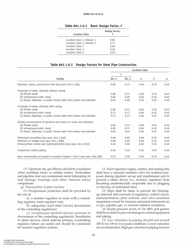
ASME B31.8-2012
Table 841.1.6-1 Basic Design Factor, F
Design Factor,Location Class F
Location Class 1, Division 1 0.80Location Class 1, Division 2 0.72Location Class 2 0.60Location Class 3 0.50Location Class 4 0.40
Table 841.1.6-2 Design Factors for Steel Pipe Construction
Location Class
1
Facility Div. 1 Div. 2 2 3 4
Pipelines, mains, and service lines [see para. 841.2.1(b)] 0.80 0.72 0.60 0.50 0.40
Crossings of roads, railroads without casing:(a) Private roads 0.80 0.72 0.60 0.50 0.40(b) Unimproved public roads 0.60 0.60 0.60 0.50 0.40(c) Roads, highways, or public streets with hard surface and railroads 0.60 0.60 0.50 0.50 0.40
Crossings of roads, railroads with casing:(a) Private roads 0.80 0.72 0.60 0.50 0.40(b) Unimproved public roads 0.72 0.72 0.60 0.50 0.40(c) Roads, highways, or public streets with hard surface and railroads 0.72 0.72 0.60 0.50 0.40
Parallel encroachment of pipelines and mains on roads and railroads:(a) Private roads 0.80 0.72 0.60 0.50 0.40(b) Unimproved public roads 0.80 0.72 0.60 0.50 0.40(c) Roads, highways, or public streets with hard surface and railroads 0.60 0.60 0.60 0.50 0.40
Fabricated assemblies [see para. 841.1.9(a)] 0.60 0.60 0.60 0.50 0.40Pipelines on bridges [see para. 841.1.9(b)] 0.60 0.60 0.60 0.50 0.40Pressure/flow control and metering facilities [see para. 841.1.9(c)] 0.60 0.60 0.60 0.50 0.40
Compressor station piping 0.50 0.50 0.50 0.50 0.40
Near concentration of people in Location Classes 1 and 2 [see para. 840.3(b)] 0.50 0.50 0.50 0.50 0.40
(2) Upstream dry gas filter(s) should be consideredwhen installing rotary or turbine meters. Particulatesand pipeline dust can contaminate meter lubricating oiland damage bearings and other internal metercomponents.
(g) Pressure/Flow Control Facilities(1) Overpressure protection shall be provided by
the use of(a) a monitor regulator in series with a control-
ling regulator (each regulator run)(b) adequately sized relief valve(s) downstream
of the controlling regulator(s)(c) overpressure shutoff valve(s) upstream or
downstream of the controlling regulator(s). Installationof alarm devices which indicate primary (controlling)regulator failure are useful and should be consideredfor monitor regulator systems.
40
(2) Each regulator supply, control, and sensing lineshall have a separate isolation valve for isolation pur-poses during regulator set-up and maintenance and toprevent a safety device (i.e., monitor, regulator) frombecoming unintentionally inoperable due to pluggingor freezing of instrument lines.
(3) Steps shall be taken to prevent the freezing-up (internal and external) of regulators, control valves,instrumentation, pilot controls, and valve actuationequipment caused by moisture saturated instrument airor gas, pipeline gas, or external ambient conditions.
(4) Sound pressure levels of 110 dBA and greatershall be avoided to prevent damage to control equipmentand piping.
(5) Gas velocities in piping should not exceed100 ft/sec (30 m/s) at peak conditions. Lower velocitiesare recommended. High gas velocities in piping increase
Copyright ASME International Provided by IHS under license with ASME No reproduction or networking permitted without license from IHS

ASME B31.8-2012
Table 841.1.7-1 Longitudinal Joint Factor, E
Spec. No. Pipe Class E Factor
ASTM A53 Seamless 1.00Electric-Resistance-Welded 1.00Furnace-Butt Welded, Continuous Weld 0.60
ASTM A106 Seamless 1.00ASTM A134 Electric-Fusion Arc-Welded 0.80ASTM A135 Electric-Resistance-Welded 1.00ASTM A139 Electric-Fusion Arc-Welded 0.80ASTM A333 Seamless 1.00
Electric-Resistance-Welded 1.00ASTM A381 Submerged-Arc-Welded 1.00ASTM A671 Electric-Fusion-Welded
Classes 13, 23, 33, 43, 53 0.80Classes 12, 22, 32, 42, 52 1.00
ASTM A672 Electric-Fusion-WeldedClasses 13, 23, 33, 43, 53 0.80Classes 12, 22, 32, 42, 52 1.00
ASTM A691 Electric-Fusion-WeldedClasses 13, 23, 33, 43, 53 0.80Classes 12, 22, 32, 42, 52 1.00
ASTM A984 Electric-Resistance-Welded 1.00ASTM A1005 Double Submerged-Arc-Welded 1.00ASTM A1006 Laser Beam Welded 1.00API 5L Electric Welded 1.00
Seamless 1.00Submerged-Arc Welded (Longitudinal 1.00Seam or Helical Seam)Furnace-Butt Welded, Continuous Weld 0.60
GENERAL NOTE: Definitions for the various classes of welded pipeare given in para. 804.7.3.
Table 841.1.8-1 Temperature Derating Factor,T, for Steel Pipe
Temperature DeratingTemperature, °F (°C) Factor, T
250 (121) or lower 1.000300 (149) 0.967350 (177) 0.933400 (204) 0.900450 (232) 0.867
GENERAL NOTE: For intermediate temperatures, interpolate for derat-ing factor.
turbulence and pressure drop and contribute to exces-sive sound pressure levels (aerodynamic noise) and cancause internal piping erosion.
(h) Other (Nonmandatory) Considerations for Pressure/Flow Control Facilities
(1) Filtration of gas, particularly for instrumenta-tion, instrument regulators, etc., should be consideredwhere particulate contaminants are a present or poten-tial problem.
(2) Installation of conical reducers immediatelydownstream of a regulator or control valve will allowa more gradual expansion of gas to larger piping and
41
reduce turbulence and pressure drop during gasexpansion.
(i) Electrical Facilities and Electronic Equipment forPressure/Flow Control and Metering Facilities
(1) All electrical equipment and wiring installed inpressure/flow control facilities and metering facilitiesshall conform to the requirements of NFPA 70 and otherapplicable electrical codes. Additional API and AGAreferences are listed in Nonmandatory Appendix C.
(2) Electronic control, monitoring, and gas mea-surement equipment shall be properly grounded andisolated from piping to help prevent overpressure/accidental shutoff situations caused by equipment fail-ure due to lightning strikes and electrical transients andto prevent safety hazards caused by fault currents. Elec-trical isolation equipment for corrosion control purposesshould not be installed in buildings unless specificallydesigned to be used in combustible atmospheres.
(3) Uninterruptible power sources or redundantback-up systems should be considered to help preventoverpressure/unintentional shutoff situations caused bypower outages.
(4) A useful reference for electronic gas measure-ments is API Manual of Petroleum MeasurementStandards, Chapter 21 – Flow Measurement UsingElectronic Metering Systems, Section 1 — Electronic GasMeasurement.
(j) Pipeline Installation by Directional Drilling(1) Qualifications. Drilling contractors shall main-
tain written design and installation proceduresaddressing crossings to be completed by the directionaldrilling method. Drilling equipment operators and per-sonnel responsible for establishing the location of thepilot head and reamer during drilling operations shallbe qualified by training and experience in the implemen-tation of the contractor’s procedures.
(2) Geotechnical Evaluations. Geotechnical evalua-tions should be considered at the crossing location toestablish subsurface conditions.
(3) Installation Forces and Stresses. Loads on, andstresses in, the pipe string during installation shall beevaluated to ensure protection of the pipe against yield-ing, buckling, collapse, and undesired movement of thepipe string due to the combined effects of external pres-sure, friction, axial forces, and bending. (See directionaldrilling references in Nonmandatory Appendix C.)
(4) Protective Coating. The frictional and abrasiveforces that may be exerted on the pipe coating duringinstallation shall be consideredwhen specifying the typeof coating system to be applied to the pipe and weldjoints. During installation, care shall be taken to protectthe quality and integrity of the external corrosioncoating.
(5) Additional Evaluation Measures. In addition tothe minimum inspection and post-inspection testingrequirements of this Code, consideration shall be given
Copyright ASME International Provided by IHS under license with ASME No reproduction or networking permitted without license from IHS

(12)
ASME B31.8-2012
to performing the following additional measures on thepipe string:
(a) nondestructive examination of 100% of all cir-cumferential welds prior to installation
(b) pressure testing (pretest) of the fabricatedpipe string prior to installation
(c) passing an internal sizing plate, caliper tool,or instrumented inspection device through the pipestring following installation
(6) Damage Prevention. To minimize the potentialfor damage to existing surface or subsurface structures,design of the crossing plan and profile shall considerthe accuracy of the methods to be employed in locatingexisting structures, maintaining required clearancesfrom existing structures, tracking the position of thepilot head and reamer during drilling operations, andtracking of the reamer during pullback.
Prior to the commencement of drilling operations, thelocation of all subsurface structures in near proximityto the design drill path shall, where practical, be exposedto permit a visual confirmation of the structure’slocation.
Prior to initiating the reaming operation, consider-ation shall be given to the potential impact of the opera-tion on all adjacent structures due to any realizeddeviations from the design path.
(k) Other (Nonmandatory) Considerations for PressureCycle Fatigue of Longitudinal Pipe Seams. Line pipe longi-tudinal seams are not generally regarded as susceptibleto fatigue due to operational pressure cycles in mostnatural gas service. Evaluation of the potential forfatigue crack growth due to pressure cycles is recom-mended for pipe containing longitudinal seams wherethe expected lifetime accumulation of full MAOP cyclesmay exceed the following number of occurrences:
(U.S. Customary Units)
N p6.0 e17
(F � S)3 � t0.5
(SI Units)
N p9.8 e11
(F � S)3 � t0.5
whereF p design factor from Table 841.1.6-1N p equivalent number of cycles during the expected
service life of the piping systemS p specified minimum yield strength, psi (MPa),
stipulated in the specification under which thepipe was purchased from the manufacturer ordetermined in accordance with paras. 817.1.3(h)and 841.1.4
t p nominal wall thickness, in. (mm)
The pipeline is considered not susceptible to fatiguein the longitudinal seams due to pressure cycles if the
42
pipeline has been exposed to a hydrostatic test at apressure level at least 1.25 times the MAOP, and theexpected lifetime accumulation of full-MAOP cycles isN or fewer, or the design factor, F, is 0.4 or less. Forpurposes of applying this screening criterion, pressurecycles larger than 50% of the MAOP in magnitudeshould be counted as full-MAOP cycles. Seam weldsthat are not oriented parallel to the longitudinal axis ofthe pipe are exempt from the evaluation.
841.1.10 Protection of Pipelines and Mains FromHazards
(a) When pipelines and mains must be installedwhere they will be subject to natural hazards, such aswashouts, floods, unstable soil, landslides, earthquake-related events (such as surface faulting, soil liquefaction,and soil and slope instability characteristics), or otherconditions that may cause serious movement of, orabnormal loads on, the pipeline, reasonable precautionsshall be taken to protect the pipeline, such as increasingthe wall thickness, constructing revetments, preventingerosion, and installing anchors.
(b) Where pipelines and mains cross areas that arenormally under water or subject to flooding (i.e., lakes,bays, or swamps), sufficient weight or anchorage shallbe applied to the line to prevent flotation.
(c) Because submarine crossings may be subject towashouts due to the natural hazards of changes in thewaterway bed, water velocities, deepening of the chan-nel, or changing of the channel location in the waterway,design consideration shall be given to protecting thepipeline or main at such crossings. The crossing shallbe located in the more stable bank and bed locations.The depth of the line, location of the bends installed inthe banks, wall thickness of the pipe, and weighting ofthe line shall be selected based on the characteristics ofthe waterway.
(d) Where pipelines and mains are exposed, such asat spans, trestles, and bridge crossings, the pipelinesand mains shall be reasonably protected by distance orbarricades from accidental damage by vehicular trafficor other causes.
841.1.11 Cover, Clearance, and Casing Requirementsfor Buried Steel Pipelines and Mains
(a) Cover Requirements for Mains. Buried mains shallbe installed with a cover not less than 24 in. (610 mm).Where this cover provision cannot be met, or whereexternal loads may be excessive, the main shall beencased, bridged, or designed to withstand any suchanticipated external loads.Where farming or other oper-ations might result in deep plowing, in areas subject toerosion, or in locations where future grading is likely,such as road, highway, railroad, and ditch crossings,additional protection shall be provided [seepara. 841.1.11(e) for suggestedmethods to provide addi-tional protection].
Copyright ASME International Provided by IHS under license with ASME No reproduction or networking permitted without license from IHS

ASME B31.8-2012
Table 841.1.11-1 Pipeline Cover Requirements
Cover, in. (mm)
For RockExcavation [Note (1)]
Pipe Size Pipe SizeNPS 20 Larger Than
For Normal (DN 500) and NPS 20Location Excavation Smaller (DN 500)
Class 1 24 (610) 12 (300) 18 (460)Class 2 30 (760) 18 (460) 18 (460)Classes 3 and 4 30 (760) 24 (610) 24 (610)Drainage ditch at public 36 (910) 24 (610) 24 (610)roads and railroadcrossings (alllocations)
NOTE:(1) Rock excavation is excavation that requires blasting.
(b) Cover Requirements for Pipelines. Except for off-shore pipelines, buried pipelines shall be installed witha cover not less than that shown in Table 841.1.11-1.
Where these cover provisions cannot be met or whereexternal loads may be excessive, the pipeline shall beencased, bridged, or designed to withstand any suchanticipated external loads. In areas where farming orother operations might result in deep plowing, in areassubject to erosion, or in locations where future gradingis likely, such as at roads, highways, railroad crossings,and ditch crossings, additional protection shall be pro-vided. [See para. 841.1.11(e) for suggested methods toprovide additional protection.]
(c) Clearance Between Pipelines or Mains and OtherUnderground Structures
(1) There shall be at least 6 in. (150mm) of clearancewherever possible between any buried pipeline and anyother underground structure not used in conjunctionwith the pipeline. When such clearance cannot beattained, precautions to protect the pipe shall be taken,such as the installation of casing, bridging, or insulatingmaterial.
(2) There shall be at least 2 in. (50 mm) of clearancewherever possible between any buried gas main andany other underground structure not used in conjunc-tion with the main. When such clearance cannot beattained, precautions to protect the main shall be taken,such as the installation of insulating material or casing.
(d) Casing Requirements Under Railroads, Highways,Roads, or Streets. Casings shall be designed to withstandthe superimposed loads. Where there is a possibility ofwater entering the casing, the ends of the casing shallbe sealed. If the end sealing is of a type that will retainthemaximumallowable operating pressure of the carrierpipe, the casing shall be designed for this pressure andat least to the design factor of 0.72. Venting of sealedcasings is not mandatory; however, if vents are installed
43
they should be protected from the weather to preventwater from entering the casing. (Requirements for cross-ings within casing of railroads and highways are shownin Table 841.1.6-2.)
(e) Additional Underground Pipe Protection. The pipedesign factor, F, shall be in accordance withTable 841.1.6-2 for the crossing of roads and railroads.The guidance provided by API RP 1102, Steel PipelinesCrossing Railroads and Highways; or GRI ReportNo. 91/0284, Guidelines for Pipelines CrossingHighways; or Gas Piping Technology Committee’sGuide Material Appendix G-15, Design of UncasedPipelines Crossing of Highways and Railroads, may beconsidered for design and installation of pipeline cross-ing. The pipeline operator shall evaluate the need forextending additional pipe protection over the pipelinewhen the road or railroad right-of-way width is unde-fined based on anticipated loading from traffic or heavyequipment performing maintenance activities adjacentto the road or railroad.
Varying degrees of additional protection from third-party damage to a buried main or pipeline crossingwithin (or parallel to) the right-of-way of road or railroadmay be achieved using the following techniques, or vari-ants thereof, singly or in combination.
(1) A physical barrier or marker may be installedabove or around the pipe (see para. 851.7). If a physicalbarrier is used, the potential conflict with the right-of-waymaintenance activities should be recognized. Physi-cal barrier or marker methods include:
(a) a concrete or steel barrier placed above thepipe
(b) a concrete slab placed vertically adjacent tothe pipe on each side and extended above the top ofpipe elevation
(c) damage-resistant coating material, such asconcrete
(d) extra depth of cover additional to thatrequired in para. 841.1.11(b)
(e) buried high-visibility warning tape placedparallel to and above the pipe
(f) pipe casing [see paras. 841.1.11(d) and 861.1.6](2) A heavier wall thickness than is required by the
pipe design factor, F, in accordance with Table 841.1.6-1or Table 841.1.6-2.
(3) Pipeline alignment should be as straight andperpendicular to the road or railroad alignment as possi-ble to promote reliable marking of the pipe locationthrough the right-of-way and at the right-of-way limits.
Additional underground pipe protection shall be usedin conjunction with an effective educational program(para. 850.4.4), periodic surveillance of pipelines(para. 851.1), pipeline patrolling (para. 851.2), and utili-zation of programs that provide notification to operatorsregarding impending excavation activity, if available.
Copyright ASME International Provided by IHS under license with ASME No reproduction or networking permitted without license from IHS

ASME B31.8-2012
841.1.12 Design Factors Summary. Design factorsare summarized in Table 841.1.6-2.
841.2 Installation of Steel Pipelines and Mains841.2.1 Construction Specifications. All construc-
tion work performed on piping systems in accordancewith the requirements of this Code shall be done underconstruction specifications. The construction specifica-tions shall cover all phases of the work and shall be insufficient detail to cover the requirements of this Code.
841.2.2 Inspection Provisions(a) The operating company shall provide suitable
inspection. Inspectors shall be qualified either by experi-ence or training. The inspector shall have the authorityto order the repair or removal and replacement of anycomponent found that fails to meet the standards of thisCode.
(b) The installation inspection provisions for pipe-lines and other facilities to operate at hoop stresses of20% or more of the specified minimum yield strengthshall be adequate to make possible at least the followinginspections at sufficiently frequent intervals to ensuregood quality of workmanship.
(1) Inspect the surface of the pipe for serious surfacedefects just prior to the coating operation. [Seepara. 841.2.4(b)(1).]
(2) Inspect the surface of the pipe coating as it islowered into the ditch to find coating lacerations thatindicate the pipe might have been damaged after beingcoated.
(3) Inspect the fitup of the joints before the weld ismade.
(4) Visually inspect the stringer beads before subse-quent beads are applied.
(5) Inspect the completed welds before they arecovered with coating.
(6) Inspect the condition of the ditch bottom justbefore the pipe is lowered in, except for offshorepipelines.
(7) Inspect the fit of the pipe to the ditch beforebackfilling, except for offshore pipelines.
(8) Inspect all repairs, replacements, or changesordered before they are covered.
(9) Perform such special tests and inspections as arerequired by the specifications, such as nondestructivetesting of welds and electrical testing of the protectivecoating.
(10) Inspect backfill material prior to use andobserve backfill procedure to ensure no damage occursto the coating in the process of backfilling.
841.2.3 Bends, Miters, and Elbows in Steel Pipelinesand Mains. Changes in direction may be made by theuse of bends, miters, or elbows under the limitationsnoted below.
(a) Bends(1) A bend shall be free from buckling, cracks, or
other evidence of mechanical damage.
44
Table 841.2.3-1 Pipeline Field Cold BendRequirements
Minimum Radius ofDeflection of Bend in PipeLongitudinal Diameters
Nominal Pipe Size Axis, deg [see 841.2.3(a)(3)]
Smaller than NPS 12 841.2.3(a)(4) 18D(DN 300)
NPS 12 (DN 300) 3.2 18DNPS 14 (DN 350) 2.7 21DNPS 16 (DN 400) 2.4 24DNPS 18 (DN 450) 2.1 27DNPS 20 (DN 500) 1.9 30Dand larger
(2) The maximum degree of bending on a field coldbend may be determined by either method inTable 841.2.3-1. The first column expresses themaximumdeflection in an arc length equal to the nominal outsidediameter, and the second column expresses the mini-mum radius as a function of the nominal outsidediameter.
(3) A field cold bend may be made to a shorterminimum radius than permitted in (2) above, providedthe completed bend meets all other requirements of thissection, and the wall thickness after bending is not lessthan the minimum permitted by para. 841.1.1. This maybe demonstrated through appropriate testing.
(4) For pipe smaller than NPS 12 (DN 300), therequirements of (1) above must be met, and the wallthickness after bending shall not be less than the mini-mum permitted by para. 841.1.1. This may be demon-strated through appropriate testing.
(5) Except for offshore pipelines, when a circumfer-ential weld occurs in a bend section, it shall be subjectedto radiography examination after bending.
(6) All hot bends shall be made in accordance withASME B16.49.
(7) Wrinkle bends shall be permitted only on sys-tems operating at hoop stress levels of less than 30% ofthe specified minimum yield strength. When wrinklebends are made in welded pipe, the longitudinal weldshall be located on or near to the neutral axis of the bend.Wrinkle bends with sharp kinks shall not be permitted.Spacing of wrinkles shall be measured along the crotchof the pipe bend, and the peak-to-peak distance betweenthe wrinkles shall exceed the diameter of the pipe. Onpipe NPS 16 (DN 400) and larger, the wrinkle shall notproduce an angle of more than 11⁄2 deg per wrinkle.
(8) Incidental ripples in the pipe surface may occuralong the inside radius during the forming of cold fieldbends in some pipe. Ripples having a dimension mea-sured from peak to valley not exceeding 1% of the pipeoutside diameter are considered acceptable for all gasservice. Larger ripples may be permitted based on an
Copyright ASME International Provided by IHS under license with ASME No reproduction or networking permitted without license from IHS

ASME B31.8-2012
engineering analysis that considers the effects of pipelineconstruction and operation on the reliability of pipeaffected by such features. In addition, the bend shallmeet all other provisions of this section.
(b) Miters. Mitered bends are permitted, provided thefollowing limitations are met:
(1) In systems intended to operate at hoop stresslevels of 40% or more of the specified minimum yieldstrength, mitered bends are not permitted. Deflectionscaused by misalignment up to 3 deg are not consideredas miters.
(2) In systems intended to operate at hoop stresslevels of 10% or more but less than hoop stress levelsof 40% of the specified minimum yield strength, thetotal deflection angle at each miter shall not exceed121⁄2 deg.
(3) In systems intended to operate at hoop stresslevels of less than 10% of the specified minimum yieldstrength, the total deflection angle at each miter shallnot exceed 90 deg.
(4) In systems intended to operate at hoop stresslevels of 10% or more of the specified minimum yieldstrength, the minimum distance between miters mea-sured at the crotch shall not be less than one pipediameter.
(5) Care shall be taken in making mitered joints toprovide proper spacing and alignment and fullpenetration.
(c) Elbows. Factory-made, wrought-steel weldingelbows or transverse segments cut therefrom may beused for changes in direction, provided that the arclength measured along the crotch is at least 1 in. (25 mm)on pipe sizes NPS 2 (DN 50) and larger.
841.2.4 Pipe Surface Requirements Applicable toPipelines and Mains to Operate at a Hoop Stress of 20%or More of the Specified Minimum Yield Strength.Gouges, grooves, and notches have been found to be animportant cause of pipeline failures, and all harmfuldefects of this nature must be prevented, eliminated, orrepaired. Precautions shall be takenduringmanufacture,hauling, and installation to prevent the gouging orgrooving of pipe.
(a) Detection of Gouges and Grooves(1) The field inspection provided on each job shall
be suitable to reduce to an acceptable minimum thechances that gouged or grooved pipe will get into thefinished pipeline or main. Inspection for this purposejust ahead of the coating operation and during thelowering-in and backfill operation is required.
(2) When pipe is coated, inspection shall be madeto determine that the coating machine does not causeharmful gouges or grooves.
(3) Lacerations of the protective coating shall becarefully examined prior to the repair of the coating todetermine if the pipe surface has been damaged.
(b) Field Repair of Gouges and Grooves
45
(1) Injurious gouges or grooves shall be removed.(2) Gouges or groovesmay be removed by grinding
to a smooth contour, provided that the resulting wallthickness is not less than theminimumprescribed by thisCode for the conditions of usage. [See para. 841.1.5(b).]
(3) When the conditions outlined inpara. 841.2.4(b)(2) cannot be met, the damaged portionof pipe shall be cut out as a cylinder and replaced witha good piece. Insert patching is prohibited.
(c) Dents(1) A dent may be defined as a depression that
produces a gross disturbance in the curvature of the pipewall (as opposed to a scratch or gouge, which reducesthe pipe wall thickness). The depth of a dent shall bemeasured as the gap between the lowest point of thedent and a prolongation of the original contour of thepipe in any direction.
(2) A dent, as defined in para. 841.2.4(c)(1), whichcontains a stress concentrator such as a scratch, gouge,groove, or arc burn shall be removed by cutting out thedamaged portion of the pipe as a cylinder.
(3) All dents that affect the curvature of the pipeat the longitudinal weld or any circumferential weldshall be removed. All dents that exceed a maximumdepth of 1⁄4 in. in pipe NPS 12 (DN 300) and smaller or2% of the nominal pipe diameter in all pipe greater thanNPS 12 (DN 300) shall not be permitted in pipelines ormains intended to operate at hoop stress levels of 40%or more of the specified minimum yield strength. Whendents are removed, the damaged portion of the pipeshall be cut out as a cylinder. Insert patching and pound-ing out of the dents is prohibited.
(d) Notches(1) Notches on the pipe surface can be caused by
mechanical damage in manufacture, transportation,handling, or installation, and when determined to bemechanically caused, shall be treated the same as gougesand grooves in para. 841.2.4(a).
(2) Stress concentrations that may or may notinvolve a geometrical notch may also be created by aprocess involving thermal energy in which the pipe sur-face is heated sufficiently to change its mechanical ormetallurgical properties. These imperfections aretermed “metallurgical notches.” Examples include anarc burn produced by accidental contact with a weldingelectrode or a grinding burn produced by excessive forceon a grinding wheel. Metallurgical notches may resultin evenmore severe stress concentrations than amechan-ical notch and shall be prevented or eliminated in allpipelines intended to operate at hoop stress levels of20% or more of the specified minimum yield strength.
(e) Elimination of Arc Burns. The metallurgical notchcaused by arc burns shall be removed by grinding, pro-vided the grinding does not reduce the remaining wallthickness to less than the minimum prescribed by this
Copyright ASME International Provided by IHS under license with ASME No reproduction or networking permitted without license from IHS

ASME B31.8-2012
Code for the conditions of use.1 In all other cases, repairis prohibited, and the portion of pipe containing the arcburn must be cut out as a cylinder and replaced with agood piece. Insert patching is prohibited. Care shall beexercised to ensure that the heat of grinding does notproduce a metallurgical notch.
841.2.5 Miscellaneous Operations Involved in theInstallation of Steel Pipelines and Mains
(a) Handling, Hauling, and Stringing. Care shall betaken in the selection of the handling equipment and inhandling, hauling, unloading, and placing the pipe soas not to damage the pipe.
(b) Installation of Pipe in the Ditch. On pipelinesoperating at hoop stress levels of 20% or more of thespecified minimum yield strength, it is important thatstresses imposed on the pipeline by construction bemin-imized. Except for offshore pipelines, the pipe shall fitthe ditch without the use of external force to hold it inplace until the backfill is completed. When long sectionsof pipe that have been welded alongside the ditch arelowered in, care shall be exercised so as not to jerkthe pipe or impose any strains that may kink or put apermanent bend in the pipe. Slack loops are not prohib-ited by this paragraph where laying conditions rendertheir use advisable.
(c) Backfilling(1) Backfilling shall be performed in a manner to
provide firm support under the pipe.(2) If there are large rocks in the material to be used
for backfill, care shall be used to prevent damage to thecoating by such means as the use of rock shield material,or by making the initial fill with rock-free material suffi-cient to prevent damage.
(3) Where the trench is flooded to consolidate thebackfill, care shall be exercised to see that the pipe isnot floated from its firm bearing on the trench bottom.
841.2.6 Hot Taps. All hot taps shall be installed bytrained and experienced crews.
841.2.7 Precautions to Avoid Explosions of Gas–AirMixtures or Uncontrolled Fires During ConstructionOperations
(a) Operations such as gas or electric welding andcutting with cutting torches can be safely performedon pipelines, mains, and auxiliary equipment, providedthat they are completely full of gas or air that is free fromcombustible material. Steps shall be taken to prevent amixture of gas and air at all pointswhere such operationsare to be performed.
1 Complete removal of the metallurgical notch created by an arcburn can be determined as follows: After visible evidence of thearc burn has been removed by grinding, swab the ground areawith a 20% solution of ammonium persulfate. A blackened spotis evidence of a metallurgical notch and indicates that additionalgrinding is necessary.
46
(b) When a pipeline or main can be kept full of gasduring a welding or cutting operation, the followingprocedures are recommended:
(1) Keep a slight flow of gas moving toward thepoint where cutting or welding is being done.
(2) Control the gas pressure at the site of the workby a suitable means.
(3) After a cut is made, immediately close all slotsor open ends with tape, tightly fitted canvas, or othersuitable materials.
(4) Do not permit two openings to remain uncov-ered at the same time. This is doubly important if thetwo openings are at different elevations.
(c) Welding, cutting, or other operations that couldbe a source of ignition shall not be done on a pipeline,main, or auxiliary apparatus that contains air, if it isconnected to a source of gas, unless a suitable means hasbeen provided to prevent the formation of an explosivemixture in the work area.
(d) In situations where welding or cutting must bedone on facilities that are filled with air and connectedto a source of gas, and the precautions recommendedabove cannot be taken, one or more of the followingprecautions, depending on circumstances at the jobsite,are suggested:
(1) purging of the pipe or equipment upon whichwelding or cutting is to be done with an inert gas orcontinuous purging with air in such a manner that acombustible mixture does not form in the facility at thework area
(2) testing of the atmosphere in the vicinity of thezone to be heated before the work is started and atintervals as the work progresses with a combustible gasindicator or by other suitable means
(3) careful verification before and during the workensuring that the valves that isolate the work from asource of gas do not leak
(e) Purging of Pipelines and Mains(1) When a pipeline or main is to be placed in ser-
vice, the air in it shall be displaced. The following aresome acceptable methods:
(a) Method 1. Introduce a moderately rapid andcontinuous flow of gas into one end of the line and ventthe air out the other end. The gas flow shall be continuedwithout interruption until the vented gas is free of air.
(b) Method 2. If the vent is in a location wherethe release of gas into the atmosphere may cause a haz-ardous condition, then a slug of inert gas shall be intro-duced between the gas and air. The gas flow shall thenbe continued without interruption until all of the airand inert gas have been removed from the facility. Thevented gases shall be monitored and the vent shall beclosed before any substantial quantity of combustiblegas is released to the atmosphere.
(2) In cases where gas in a pipeline or main is tobe displaced with air and the rate at which air can be
Copyright ASME International Provided by IHS under license with ASME No reproduction or networking permitted without license from IHS

ASME B31.8-2012
supplied to the line is too small to make a proceduresimilar to but the reverse of that described in (1) abovefeasible, a slug of inert gas should be introduced toprevent the formation of an explosive mixture at theinterface between gas and air. Nitrogen or carbon diox-ide can be used for this purpose.
(3) If a pipeline or main containing gas is to beremoved, the operationmay be carried out in accordancewith para. 841.2.7(b), or the line may be first discon-nected from all sources of gas and then thoroughlypurged with air, water, or inert gas before any furthercutting or welding is done.
(4) If a gas pipeline, main, or auxiliary equipmentis to be filled with air after having been in service, andthere is a reasonable possibility that the inside surfacesof the facility are wetted with volatile inflammable liq-uid, or if such liquids might have accumulated in lowplaces, purging procedures designed to meet this situa-tion shall be used. Steaming of the facility until all com-bustible liquids have been evaporated and swept out isrecommended. Filling of the facility with an inert gasand keeping it full of such gas during the progress ofany work that may ignite an explosive mixture in thefacility is an alternative recommendation. The possibil-ity of striking static sparks within the facility must notbe overlooked as a possible source of ignition.
(f) Whenever the accidental ignition in the open airof gas-air mixture may be likely to cause personal injuryor property damage, precautions shall be taken. Forexample:
(1) Prohibit smoking and open flames in the area.(2) Install a metallic bond around the location of
cuts in gas pipes to bemade bymeans other than cuttingtorches.
(3) Take precautions to prevent static electricitysparks.
(4) Provide a fire extinguisher of appropriate sizeand type, in accordance with NFPA 10.
841.3 Testing After Construction
841.3.1 General Provisions. All piping systemsshall be tested after construction to the requirements ofthis Code except for pre-tested fabricated assembliesand welded tie-in connections where post constructiontie-in testing is not practical.
Additionally, single lengths or multiple welded lengthsof pipe previously tested in accordance with this Codefor the purposes of repair or replacement do not requirea post construction retest.
(a) The circumferential welds associated with con-necting pretested assemblies, pretested repair pipelengths or sections and welded tie-in connections notpressure tested after construction shall be inspected byradiographic or other accepted nondestructive methodsin accordance with para. 826.2.
47
(b) Nonwelded tie-in connections not pressure testedafter construction shall be leak tested at not less thanthe pressure available when the tie-in is placed intoservice.
(c) Pressure testing with water is recommendedwhenever possible. However, it is recognized that cer-tain conditions may require testing with gases. When agas is used as the test medium, the test pressure shallnot exceed the maximum values stated inTables 841.3.2-1 and 841.3.3-1.
The user is cautioned that the release of stored energyin a gas test failure can be significantly more hazardousthan a similar failure with water. When testing with gas,a formal risk assessment is recommended, wherein risksare identified, and appropriate mitigating measures andpractices are identified and implemented to minimizethese additional risks.
(d) When pipeline systems are installed in unstablesoils or the mass of the test medium contributes to addi-tional stresses in the pipeline system, the stresses andreactions due to expansion, longitudinal pressure, andlongitudinal bending shall be investigated prior to test-ing. This investigation shall confirm that the test pres-sures and loads do not produce unacceptable stresses,strains, deflections, or other conditions that couldadversely impact the ability of the system to performas required.
(e) Test planning shall consider pressure test mediumtemperatures and duration of testing operations to limitdamage to pipe from freezing of the test medium andprevent detrimental pipeline deformation due to desta-bilization of permafrost soils.
(f) Each test assembly (a fabrication that is not partof the permanent facility used for filling, pressuring andmonitoring the test) shall be designed, fabricated, andinstalled in accordance with the provisions of this Code.Each test assembly shall be designed to operate at theanticipated maximum test pressure. The operator isencouraged to consider pretesting of the test assemblyprior to its use to reduce risk to testing personnel. Pre-testing of the test assembly is requiredwhen the pressuretest is to be conducted with a sour gas medium. Subse-quent retesting prior to reuse should be considered if thetest assembly is suspected to have undergone damageduring or between tests.
(g) Test assemblies should be located consideringaccessibility, sources of test medium, and the elevationprofile of the test segment. Selected locations shouldprovide testing flexibility while limiting test pressuresbetween the minimum test pressure and the selectedmaximum test pressure.
841.3.2 Pressure Test Requirements to ProveStrength of Pipelines and Mains to Operate at HoopStresses of 30% or More of the Specified Minimum YieldStrength of the Pipe. The following are pressure testrequirements to prove strength of pipelines andmains tooperate at hoop stresses of 30% or more of the specifiedminimum yield strength of the pipe:
Copyright ASME International Provided by IHS under license with ASME No reproduction or networking permitted without license from IHS

ASME B31.8-2012
Table 841.3.2-1 Test Requirements for Steel Pipelines and Mains to Operate at Hoop Stressesof 30% or More of the Specified Minimum Yield Strength of the Pipe
1 2 3 4 5 6
MaximumPressure Test PrescribedDesign Factor, Permissible Test Maximum Allowable Operating
Location Class F Medium Minimum Maximum Pressure, the Lesser of
1, Division 1 0.8 Water 1.25 � MOP None TP � 1.25 or DP
1, Division 2 0.72 Water 1.25 � MOP None TP � 1.25 or DP0.72 Air or Gas 1.25 � MOP 1.25 � DP TP � 1.25 or DP
[Note (1)]
2 0.6 Water 1.25 � MOP None TP � 1.25 or DP0.6 Air [Note (1)] 1.25 � MOP 1.25 � DP TP � 1.25 or DP
3 [Note (2)] 0.5 Water [Note (3)] 1.50 � MOP None TP � 1.5 or DP
4 0.4 Water [Note (3)] 1.50 � MOP None TP � 1.5 or DP
DP p design pressureMOP p maximum operating pressure (not necessarily the maximum allowable operating pressure)TP p test pressure
GENERAL NOTES:(a) This Table defines the relationship between test pressures and maximum allowable operating pressures subsequent to the test. If an
operating company decides that the maximum operating pressure will be less than the design pressure, a corresponding reduction inthe prescribed test pressure may be made as indicated in the Pressure Test Prescribed, Minimum column. If this reduced test pressureis used, however, the maximum operating pressure cannot later be raised to the design pressure without retesting the line to a highertest pressure. See paras. 805.2.1(d), 845.2.2, and 845.2.3.
(b) Gas piping within gas pipeline facilities (e.g., meter stations, regulator stations, etc.) is to be tested and the maximum allowableoperating pressure qualified in accordance with para. 841.3 and Tables 841.3.2-1 and 841.3.3-1 subject to the appropriate locationclass, design factor, and text medium criteria.
(c) When an air or gas test is used, the user of this Code is cautioned to evaluate the ability of the piping system to resist propagatingbrittle or ductile fracture at the maximum stress level to be achieved during the test.
NOTES:(1) When pressure testing with air or gas, see paras. 841.3.1(c), 841.3.2(a) through (c), and Table 841.3.3-1.(2) Compressor Station piping shall be tested with water to Location Class 3 pipeline requirements as indicated in para. 843.5.1(c).(3) For exceptions, see paras. 841.3.2(b) and (c).
(a) The permissible pressure test media are stated inTable 841.3.2-1. The recommended test medium is water.Sour gas as defined in para. B803 and flammable gasmayonly be used for testing purposes in Location Class 1,Division 2 locations. When either of these media areutilized, the public shall be removed to a safe distanceduring the test and testing personnel shall be equippedwith appropriate personal protective equipment. Bothsour gas and flammable gas tests must meet the testpressure limitations per Table 841.3.3-1.
(b) The pressure test medium requirements ofTable 841.3.2-1 for the pressure testing of pipelines inclass locations 3 and 4 need not apply if, at the time thepipelines are first ready for pressure testing, one or bothof the following conditions exist:
(1) ground temperature at pipe depths are suffi-ciently low during the test to cause the test medium tochange state and cause damage or blockage that woulddamage the pipe or invalidate the test and use of chemi-cal freeze depressants is not possible
(2) approved water of satisfactory quality is notreasonably available in sufficient quantity
48
(c) Where one or both of the conditions inpara. 841.3.2(b) exist, it is permissible to pressure testusing air or nonflammable, nontoxic gases as the pres-sure test medium provided that all of the following:
(1) the maximum hoop stress during pressure test-ing is less than 50% of the specified minimum yieldstrength in class 3 locations, and less than 40% of thespecified minimum yield strength in class 4 locations
(2) the maximum pressure at which the pipeline isto be operated does not exceed 80% of the maximumfield test pressure
(3) the pipe involved has been confirmed to be fitfor service and has a longitudinal joint factor of 1.00(see Table 841.1.7-1)
(d) Before being placed in service, a newly con-structed pipeline system shall be strength tested for aminimum period of two hours at a minimum pressureequal to or greater than that specified in Table 841.3.2-1after stabilization of temperatures and surges from pres-suring operations has been achieved. The minimumpressure shall be obtained and held at the highest eleva-tion in the pipeline system.
(12)
Copyright ASME International Provided by IHS under license with ASME No reproduction or networking permitted without license from IHS

ASME B31.8-2012
(e) Test requirements as a function of Location Classare summarized in Table 841.3.2-1.
(f ) In selecting the test pressure, the designer oroperating company should be aware of the provisionsof section 854 and the relationship between test pressureand operating pressure when the pipeline experiencesa future increase in the number of dwellings intendedfor human occupancy.
(g) Other provisions of this Code notwithstanding,pipelines and mains crossing highways and railroadsmay be pretested independently or tested in conjunctionwith the adjoining pipeline segments in the same man-ner and to the same pressure as the pipeline on eachside of the crossing.
(h) Other provisions of this Code notwithstanding,fabricated assemblies, including main line valve assem-blies, cross connections, river crossing headers, etc.,installed in pipelines in Location Class 1 and designedin accordance with a design factor of 0.60 as requiredin para. 841.1.9(a), may be pretested independently ortested in conjunction with the adjoining pipeline seg-ments as required for Location Class 1.
(i) Operating companies shall retain, in their files, forthe useful life of each pipeline and main, records show-ing the procedures used and the data developed in estab-lishing the maximum allowable operating pressure ofthat pipeline or main. Refer to section N-7 ofNonmandatory Appendix N for a list of suggested rec-ords for retention.
841.3.3 Tests Required to Prove Strength forPipelines and Mains to Operate at Hoop Stress Levelsof Less Than 30% of the Specified Minimum YieldStrength of the Pipe, but in Excess of 100 psig(690 kPa). Steel piping that is to operate at hoop stresslevels of less than 30% of the specified minimum yieldstrength in Class 1 Locations shall at least be testedin accordance with para. 841.3.4. In Class 2, 3, and 4Locations, such piping shall be tested in accordancewithTable 841.3.2-1, except that gas or air may be used asthe test medium within the maximum limits set inTable 841.3.3-1.
841.3.4 Leak Tests for Pipelines or Mains to Operateat 100 psig (690 kPa) or More
(a) Each pipeline and main shall be tested after con-struction andbefore beingplaced in operation to demon-strate that it does not leak. If the test indicates that a leakexists, the leak or leaks shall be located and eliminated,unless it can be determined that no undue hazard topublic safety exists.
(b) The test procedure used shall be capable of disclos-ing all leaks in the section being tested and shall beselected after giving due consideration to the volumetriccontent of the section and to its location. This requiresthe exercise of responsible and experienced judgement,rather than numerical precision.
49
Table 841.3.3-1 Maximum Hoop StressPermissible During an Air or Gas Test
Location Class, Percent ofSpecified Minimum Yield
Strength
Test Medium 2 3 4
Air or nonflammable 75 50 40nontoxic gas
Flammable gas 30 30 30
GENERAL NOTE: Refer to para. 841.3.2(c).
(c) In all cases where a line is to be stressed in astrength proof test to a hoop stress level of 20% or moreof the specified minimum yield strength of the pipe,and gas or air is the test medium, a leak test shall bemade at a pressure in the range from 100 psig (690 kPa)to that required to produce a hoop stress of 20% of theminimum specified yield, or the line shall be walkedwhile the hoop stress is held at approximately 20% ofthe specified minimum yield.
841.3.5 Leak Tests for Pipelines and Mains to Operateat Less Than 100 psig (690 kPa)
(a) Each pipeline, main, and related equipment thatwill operate at less than 100 psi (690 kPa) shall be testedafter construction and before being placed in operationto demonstrate that it does not leak.
(b) Gas may be used as the test medium at the maxi-mum pressure available in the distribution system atthe time of the test. In this case, the soap bubble testmay be used to locate leaks if all joints are accessibleduring the test.
(c) Testing at available distribution system pressuresas provided for in para. 841.3.5(b) may not be adequateif substantial protective coatings are used that wouldseal a split pipe seam. If such coatings are used, the leaktest pressure shall be 100 psig (690 kPa).
841.3.6 Safety During Tests. All testing of pipelinesand mains after construction shall be done with dueregard for the safety of employees and the public duringthe test. When air or gas is used, suitable steps shallbe taken to keep persons not working on the testingoperations out of the testing area when the hoop stressis first raised from 50% of the specified minimum yieldto the maximum test stress, and until the pressure isreduced to the maximum operating pressure.
841.4 Commissioning of Facilities
841.4.1 General. Written procedures shall be estab-lished for commissioning. Procedures shall consider thecharacteristics of the gas to be transported, the need toisolate the pipeline from other connected facilities, andthe transfer of the constructed pipeline to those responsi-ble for its operation.
Copyright ASME International Provided by IHS under license with ASME No reproduction or networking permitted without license from IHS

ASME B31.8-2012
Commissioning procedures, devices, and fluids shallbe selected to ensure that nothing is introduced into thepipeline system that will be incompatible with the gasto be transported, or with the materials in the pipelinecomponents.
841.4.2 Cleaning and Drying Procedures. Consider-ation shall be given to the need for cleaning and dryingthe pipe and its components beyond that required forremoval of the test medium.
841.4.3 Functional Testing of Equipment andSystems. As a part of commissioning, all pipeline andcompressor station monitor and control equipment andsystems shall be fully function-tested, especially includ-ing safety systems such as pig trap interlocks, pressureand flow-monitoring systems, and emergency pipelineshut-down systems. Consideration should also be givento performing a final test of pipeline valves before thegas is introduced to ensure that each valve is operatingcorrectly.
841.4.4 Start-Up Procedures and Introduction ofTransported Gas. Written start-up procedures shall beprepared before introducing the transported gas into thesystem and shall require the following:
(a) the system be mechanically complete andoperational
(b) all functional tests be performed and accepted(c) all necessary safety systems be operational(d) operating procedures be available(e) a communications system be established(f) transfer of the completed pipeline system to those
responsible for its operation
841.4.5 Documentation and Records. The followingcommissioning records shall be maintained as perma-nent records:
(a) cleaning and drying procedures(b) cleaning and drying results(c) function-testing records of pipeline monitoring(d) control equipment systems(e) completed prestart checklist
842 OTHER MATERIALS
842.1 Ductile Iron Piping Systems Requirements
842.1.1 Ductile Iron Pipe Design(a) Determination of Required Wall Thickness. Ductile
iron pipe shall be designed in accordance with the meth-ods set forth in ANSI/AWWA C150/A21.50.
(b) Allowable Values of s and f. The values of designhoop stress s and design bending stress f at the bottomof the pipe, to be used in the equations given inANSI/AWWA C150/A21.50, are
s p 16,800 psi (116 MPa)f p 36,000 psi (248 MPa)
50
(c) Standard Ductile Iron Strength and Conformance toANSI A21.52. Ductile iron pipe shall be (60-42-10) gradeand shall conform to all requirements of ANSI A21.52.Grade (60-42-10) ductile iron has the following mechani-cal properties:
Minimum tensile strength 60,000 psi (414 MPa)Minimum yield strength 42,000 psi (290 MPa)Minimum elongation 10%
(d) Allowable Thickness for Ductile Iron Pipe. The leastductile iron pipe thicknesses permitted are the lighteststandard class for each nominal pipe size as shown inANSI A21.52. Standard wall thicknesses for250 psi (1 720 kPa) maximum working pressure andstandard laying conditions at several depths of coverare shown in Table 842.1.1-1.
(e) Ductile Iron Pipe Joints(1) Mechanical Joints. Ductile iron pipe with
mechanical joints shall conform to the requirements ofANSI A21.52 and ANSI/AWWAC111/A21.11. Mechan-ical joints shall be assembled in accordance with“Notes on Installation of Mechanical Joints” inANSI/AWWA C111/A21.11.
(2) Other Joints. Ductile iron pipemay be furnishedwith other types of joints provided they are properlyqualified and meet the appropriate provisions of thisCode. Such joints shall be assembled in accordance withapplicable standards or in accordance with themanufac-turer’s written recommendations.
(3) Threaded Joints. The use of threaded joints tocouple lengths of ductile iron pipe is not recommended.
842.1.2 Installation of Ductile Iron Pipe(a) Laying. Ductile iron pipe shall be laid in accor-
dance with the applicable field conditions described inANSI/AWWA C150/A21.50.
(b) Cover. Underground ductile iron pipe shall beinstalledwith aminimumcover of 24 in. (610mm)unlessprevented by other underground structures. Where suf-ficient cover cannot be provided to protect the pipe fromexternal loads or damage and the pipe is not designedto withstand such external loads, the pipe shall be casedor bridged to protect the pipe.
(c) Joint Restraint. Suitable harnessing or buttressingshall be provided at points where the main deviatesfrom a straight line and the thrust, if not restrained,would separate the joints.
(d) Making Ductile Iron Field Joints. Ductile iron pipejoints shall conform to para. 842.1.1(e) and shall beassembled according to recognized American NationalStandards or in accordance with the manufacturer’swritten recommendations.
842.1.3 Testing Ductile Iron Field Joints. Ductileiron pipe joints shall be leak tested in accordance withpara. 841.3.4 or 841.3.5.
Copyright ASME International Provided by IHS under license with ASME No reproduction or networking permitted without license from IHS

(12)
ASME B31.8-2012
Table 842.1.1-1 Standard Thickness Selection Table for Ductile Iron Pipe
Thickness, in. (mm), for Depth of Cover, ft (m)Nominal Pipe LayingSize, NPS (DN) Condition 21/2 31/2 5 8 12 16 20 24
3 (75) A 0.28 (7.1) 0.28 (7.1) 0.28 (7.1) 0.28 (7.1) 0.28 (7.1) 0.28 (7.1) 0.28 (7.1) 0.28 (7.1)B 0.28 (7.1) 0.28 (7.1) 0.28 (7.1) 0.28 (7.1) 0.28 (7.1) 0.28 (7.1) 0.28 (7.1) 0.28 (7.1)
4 (100) A 0.29 (7.4) 0.29 (7.4) 0.29 (7.4) 0.29 (7.4) 0.29 (7.4) 0.29 (7.4) 0.29 (7.4) 0.29 (7.4)B 0.29 (7.4) 0.29 (7.4) 0.29 (7.4) 0.29 (7.4) 0.29 (7.4) 0.29 (7.4) 0.29 (7.4) 0.29 (7.4)
6 (150) A 0.31 (7.9) 0.31 (7.9) 0.31 (7.9) 0.31 (7.9) 0.31 (7.9) 0.31 (7.9) 0.31 (7.9) 0.31 (7.9)B 0.31 (7.9) 0.31 (7.9) 0.31 (7.9) 0.31 (7.9) 0.31 (7.9) 0.31 (7.9) 0.31 (7.9) 0.31 (7.9)
8 (200) A 0.33 (8.4) 0.33 (8.4) 0.33 (8.4) 0.33 (8.4) 0.33 (8.4) 0.33 (8.4) 0.33 (8.4) 0.33 (8.4)B 0.33 (8.4) 0.33 (8.4) 0.33 (8.4) 0.33 (8.4) 0.33 (8.4) 0.33 (8.4) 0.33 (8.4) 0.33 (8.4)
10 (250) A 0.35 (8.9) 0.35 (8.9) 0.35 (8.9) 0.35 (8.9) 0.35 (8.9) 0.35 (8.9) 0.38 (9.7) 0.38 (9.7)B 0.35 (8.9) 0.35 (8.9) 0.35 (8.9) 0.35 (8.9) 0.35 (8.9) 0.35 (8.9) 0.38 (9.7) 0.38 (9.7)
12 (300) A 0.37 (9.4) 0.37 (9.4) 0.37 (9.4) 0.37 (9.4) 0.37 (9.4) 0.37 (9.4) 0.40 (10.2) 0.43 (10.9)B 0.37 (9.4) 0.37 (9.4) 0.37 (9.4) 0.37 (9.4) 0.37 (9.4) 0.37 (9.4) 0.40 (10.2) 0.40 (10.2)
14 (350) A 0.36 (9.1) 0.36 (9.1) 0.36 (9.1) 0.36 (9.1) 0.39 (9.9) 0.42 (10.7) 0.45 (11.4) 0.45 (11.4)B 0.36 (9.1) 0.36 (9.1) 0.36 (9.1) 0.36 (9.1) 0.36 (9.1) 0.42 (10.7) 0.42 (10.7) 0.45 (11.4)
16 (400) A 0.37 (9.4) 0.37 (9.4) 0.37 (9.4) 0.37 (9.4) 0.40 (10.2) 0.43 (10.9) 0.46 (11.7) 0.49 (12.4)B 0.37 (9.4) 0.37 (9.4) 0.37 (9.4) 0.37 (9.4) 0.40 (10.2) 0.43 (10.9) 0.46 (11.7) 0.49 (12.4)
18 (450) A 0.38 (9.7) 0.38 (9.7) 0.38 (9.7) 0.38 (9.7) 0.41 (10.4) 0.47 (11.9) 0.50 (12.7) 0.53 (13.5)B 0.38 (9.7) 0.38 (9.7) 0.38 (9.7) 0.38 (9.7) 0.41 (10.4) 0.44 (11.2) 0.47 (11.9) 0.53 (13.5)
20 (500) A 0.39 (9.9) 0.39 (9.9) 0.39 (9.9) 0.39 (9.9) 0.45 (11.4) 0.48 (12.2) 0.54 (13.7) . . .B 0.39 (9.9) 0.39 (9.9) 0.39 (9.9) 0.39 (9.9) 0.42 (10.7) 0.48 (12.2) 0.51 (13.0) . . .
24 (600) A 0.44 (11.2) 0.41 (10.4) 0.41 (10.4) 0.44 (11.2) 0.50 (12.7) 0.56 (14.2) . . . . . .B 0.41 (7.9) 0.41 (7.9) 0.41 (7.9) 0.41 (7.9) 0.47 (11.9) 0.53 (13.5) . . . . . .
GENERAL NOTES:(a) This Table is taken from ANSI A21.52.(b) Laying Condition A: flat-bottom trench without blocks, untamped backfill.(c) Laying Condition B: flat-bottom trench without blocks, tamped backfill.(d) The thicknesses in this Table are equal to or in excess of those required to withstand 250 psi (1 720 kPa) working pressure.(e) All thicknesses shown in this Table for the depths of cover indicated are adequate for trench loads including truck superloads.(f) For the basis of design, see ANSI/AWWA C150/A21.50.(g) Thread engagement in taps for service connections and bag holes may require consideration in selecting pipe thicknesses. See Appen-
dix of ANSI A21.52.
842.2 Design of Plastic Piping
General Provisions.The design requirements of this sec-tion are intended to limit the use of plastic piping pri-marily to mains and service lines in typical PVC(polyvinyl chloride) distribution systems2 operating ata pressure of 100 psig (690 kPa) or less, PE (polyethylene)distribution systems operating at a pressure of 125 psig(860 kPa) or less, and PA-11 (polyamide 11) distributionsystems operating at pressures up to the design pressureof the material as determined by the formulas inpara. 841.2.1. For other applications in Class 1 or 2Locations, plastic piping may be used within the limita-tions prescribed in this Code. Plastic piping shall meet
2 Under ASTM D2513, PVC piping may be used only for repairand maintenance of existing PVC installations.
51
the requirements of a specification listed in MandatoryAppendix A.
842.2.1 Plastic Pipe and Tubing Design Formula.The design pressure for plastic gas piping systems orthe nominal wall thickness for a given design pressure(subject to the limitations in para. 842.2.2) shall be deter-mined by the following formulas:
(U.S. Customary Units)
P p2S
(SDR) − 1� Df
or
P p2St
D − t� Df
(12)
Copyright ASME International Provided by IHS under license with ASME No reproduction or networking permitted without license from IHS

ASME B31.8-2012
(SI Units)
P p2 000S
(SDR) − 1� Df
or
P p2 000St
D − t� Df
whereD p specified outside diameter, in. (mm), in the case
of reinforced thermosetting plastic (RTP) pipe,the specified outside diameter of the reinforcedthermoset layer
Df p design factor p 0.32 or 0.40 for PA-11. Thedesign factor is a number less than or equal to1 that is multiplied by the calculated maximumpressure to obtain the design pressure.
DR p dimension ratio, the ratio of the average speci-fied outside diameter to the specified minimumwall thickness
P p design pressure, gage, psig (kPa)S p for thermoplastic pipe, hydrostatic design basis
(HDB) determined in accordance with ASTMD2837 at a temperature equal to 73°F (23°C),100°F (38°C), 120°F (49°C), or 140°F (60°C). Inthe absence of a HDB established at the speci-fied temperature, the HDB of a higher tempera-ture may be used in determining a designpressure rating at the specificed temperature byarithmetic interpolation using the procedure inPart D.2 of PPI TR-3. For RTP pipe NPS 6(DN 150) and below, used in Class 1 and 2locations, the HDB determined in accordancewith the listed specification. For all other RTPpipe, use 11,000 psi (76 MPa).
SDR p standard dimension ratio, the ratio of the aver-age specified outside diameter to the minimumspecified wall thickness, corresponding to avalue from a common numbering system thatwas derived from the American NationalStandards Institute preferred number series 10.In the case of RTP pipe, SDR is the ratio ofthe average outside diameter of the reinforcedthermoset layer to the minimum specified wallthickness of the reinforced thermoset layer. DRmay be substituted for SDR in this calculationwhen the dimension ratio is not an abovedefined “standard” dimension ratio.
t p specified wall thickness, in. (mm), in the caseof RTP pipe, the specified wall thickness of thereinforced thermoset layer
NOTE: Long-termhydrostatic strength at 73°F (23°C) for the plas-tic materials whose specifications are incorporated by referenceherein are given in Mandatory Appendix D.
52
842.2.2 Thermoplastic Design Limitations(a) Except as provided in paras. 842.2.2(e) and (f),
the design pressure may not exceed a gage pressure of100 psig (689 kPa) for plastic pipe used in
(1) distribution systems(2) Location Classes 3 and 4
(b) Plastic pipe shall not be used where the designtemperature of the pipe will be
(1) below −40°F (−40°C). In no case shall the pipeor piping components be used in applications beyondthe manufacturer’s recommended ratings for the pipeor piping component.
(2) above the temperature at which the HDB usedin the design formula is determined.
(c) The value of t for thermoplastic pipe shall not beless than that shown in Table 842.2.2-1.
(d) For saddle type service connections made by heatfusion techniques, it may be necessary for some materi-als that are intended for use at high operating pressuresto require a heavier wall thickness than defined by thepressure design formula for sizes NPS 2 (DN 50) andsmaller. Manufacturers of the specific pipe materialshould be contacted for recommendations or a qualifiedprocedure shall be used.
(e) The design pressure for PE pipe may exceed agage pressure of 100 psig (689 kPa), provided that
(1) the design pressure does not exceed 125 psig(862 kPa).
(2) the material is a PE material as specified withinASTM D2513.
(3) the pipe size is NPS 12 (DN 300) or smaller.(4) the design pressure is determined in accordance
with the design equation defined in para. 842.2.1.(f) Polyamide-11 (PA-11) pipe may be operated at
pressures up to its design pressure as determined inaccordance with the design equation defined in para.842.2.1.
842.2.3 Reinforced Thermosetting Plastic (RTP)Design Limitations
(a) The value of P for RTP mains and service lines indistribution systems in Class 3 and 4 locations shall notexceed 100 psig (689 kPa) except as prescribed in para.842.2.3(d).
(b) Reinforced thermosetting plastic pipe and fittingsshall not be used where operating temperatures willbe below −20°F (−29°C), or above 150°F (66°C), and ifrecommended by the manufacturer, up to 180°F (82°C).
(c) The wall thickness for RTP pipe shall not be lessthan that listed in Table 842.2.3-1.
(d) RTP pipe may be operated at pressures up to itsdesign pressure as determined in accordance with theequation in para. 842.2.1.
842.2.4 Design Pressure of Plastic Fittings. Themaximum pressure rating for fittings shall be the same
(12)
(12)
Copyright ASME International Provided by IHS under license with ASME No reproduction or networking permitted without license from IHS

(12)
ASME B31.8-2012
Table 842.2.2-1 Wall Thickness and Standard Dimension Ratio forThermoplastic Pipe
Outside Minimum Wall Thickness, in. (mm), for Standard Dimension Ratio, RNominal Pipe Diameter,Size, NPS (DN) in. (mm) 26 21 17 13.5 11
1⁄2 (15) 0.840 (21.3) 0.062 (1.57) 0.062 (1.57) 0.062 (1.57) 0.062 (1.57) 0.076 (1.93)3⁄4 (20) 1.050 (26.7) 0.090 (2.29) 0.090 (2.29) 0.090 (2.29) 0.090 (2.29) 0.095 (2.41)1 (25) 1.315 (33.4) 0.090 (2.29) 0.090 (2.29) 0.090 (2.29) 0.097 (2.46) 0.119 (3.02)11⁄4 (32) 1.660 (42.2) 0.090 (2.29) 0.090 (2.29) 0.098 (2.49) 0.123 (3.12) 0.151 (3.84)11⁄2 (40) 1.900 (48.3) 0.090 (2.29) 0.090 (2.29) 0.112 (2.84) 0.141 (3.58) 0.173 (4.39)2 (50) 2.375 (60.3) 0.091 (2.31) 0.113 (2.87) 0.140 (3.56) 0.176 (4.47) 0.216 (5.49)21⁄2 (65) 2.875 (73.0) 0.110 (2.79) 0.137 (3.48) 0.169 (4.29) 0.213 (5.41) . . .3 (75) 3.500 (88.9) 0.135 (3.43) 0.167 (4.24) 0.206 (5.23) 0.259 (6.58) . . .31⁄2 (90) 4.000 (101.6) 0.154 (3.91) 0.190 (4.83) 0.236 (5.99) 0.296 (7.52) . . .4 (100) 4.500 (114.3) 0.173 (4.39) 0.214 (5.44) 0.264 (6.71) 0.333 (8.46) . . .5 (125) 5.563 (141.3) 0.224 (5.69) 0.265 (6.73) 0.328 (8.33) 0.413 (10.49) . . .6 (150) 6.625 (168.3) 0.255 (6.48) 0.316 (8.03) 0.390 (9.91) 0.491 (12.47) . . .
GENERAL NOTES:(a) Standard Dimension Ratio. The Standard Dimension Ratio System enables the user to select a number of different sizes of pipe for a
piping system, all of which will have the same design pressure. When plastic materials of the same design strengths are used, thesame Standard Dimension Ratio may be used for all sizes of pipe instead of calculating a value of t for each size.
(b) Wall thicknesses above the line are minimum values and are not a function of the Standard Dimension Ratio.
Table 842.2.3-1 Diameter and Wall Thickness forReinforced Thermosetting Plastic Pipe
Nominal Pipe Size, Outside Diameter, Minimum Thickness,NPS (DN) in. (mm) in. (mm)
2 (50) 2.375 (60.3) 0.060 (1.52)3 (75) 3.500 (88.9) 0.060 (1.52)4 (100) 4.500 (114.3) 0.070 (1.78)6 (150) 6.625 (168.3) 0.100 (2.54)
value as the maximum design pressure of the corres-ponding pipe size and wall thickness as indicated in thereferenced standard for the fittings and as determinedin paras. 842.2.1 and 842.2.2. The manufacturer shouldbe consulted for advice on maximum pressure ratingsfor fittings not covered by referenced standards.
842.2.5 Valves in Plastic Piping(a) Valves in plastic piping may be made of any suit-
able material and design permitted by this Code. Ther-moplastic valves shall comply with ASTM D2513 andASME B16.40.
(b) Valve installations in plastic piping shall be sodesigned as to protect the plastic material against exces-sive torsional or shearing loadswhen the valve or shutoffis operated, and from any other secondary stresses thatmight be exerted through the valve or its enclosure.
842.2.6 Protection From Hazards. Plastic pipingshall conform to the applicable provisions ofpara. 841.1.10.
53
842.2.7 Cover and Casing Requirements UnderRailroads, Roads, Streets, or Highways. Plastic pipingshall conform to the applicable requirements ofparas. 841.1.11(a) and (d). Where plastic piping must becased or bridged, suitable precautions shall be taken toprevent crushing or shearing of the piping. (See alsopara. 842.3.3.)
842.2.8 Clearance Between Mains and OtherUnderground Structures. Plastic piping shall conformto the applicable provisions of para. 841.1.11(c). Suffi-cient clearance shall be maintained between plastic pip-ing and steam, hot water, or power lines and othersources of heat to prevent operating temperatures inexcess of the limitations of para. 842.2.2(b) or 842.2.3(b).
842.2.9 Plastic Pipe and Tubing Joints andConnections
(a) General Provisions. Plastic pipe, tubing, and fit-tingsmay be joined by the solvent cementmethod, adhe-sive method, heat-fusion method, or by means ofcompression couplings or flanges. The method usedmust be compatible with the materials being joined. Therecommendations of the manufacturer shall be consid-ered when determining the method to be used.
(b) Joint Requirements(1) Pipe or tubing shall not be threaded.(2) Solvent cement joints, adhesive joints, and heat-
fusion joints shall be made in accordance with qualifiedprocedures that have been established and proven bytest to produce gas-tight joints at least as strong as thepipe or tubing being joined.
(12)
Copyright ASME International Provided by IHS under license with ASME No reproduction or networking permitted without license from IHS

ASME B31.8-2012
(3) Joints shall be made by personnel qualified bytraining or experience in the proper procedures requiredfor the type of joint involved.
(4) Solvent cement shall be used only on PVC joints.(5) Heat-fusion or mechanical joints shall be used
when joiningpolyethylene or polyamide 11 pipe, tubing,or fittings. PA-11 components may be joined to PA-11components, and PE components may be joined toPE components. PE and PA-11 components shall notbe heat-fused to each other. Polyethylene componentsmade of different grades of materials may be heat-fused,provided that properly qualified procedures for joiningthe specific components are used. Any combination ofPE materials with an ASTM D2513, Table 4, PipeCategory, melt index category C may be joined by heatfusion procedures such as those detailed in PPI TR-33.PPI, the Plastics Pipe Institute, publishes two genericheat fusion procedures for joining PE:
(a) TR-33, Generic Butt Fusion Joining Procedurefor Polyethylene Gas Piping
(b) TR-41, Generic Saddle Fusion Joining Proce-dure for Polyethylene Gas Piping
Fusion of PE components with different melt catego-ries may require “dissimilar fusion” procedures pro-vided by the manufacturer.
(6) Flanges or special joints may be used providedthey are properly qualified and used in accordance withthe appropriate provisions of this Code.
(c) Solvent Cement Joints(1) Square cut ends free of burrs are required for a
proper socket joint.(2) Proper fit between the pipe or tubing and mat-
ing socket or sleeve is essential to a good joint. Soundjoints cannot normally be made between loose or verytight fitting components.
(3) The mating surfaces must be clean, dry, and freeof material that may be deterimental to the joint.
(4) Solvent cements that conform to ASTM D2513and are recommended by the pipe or tubing manufac-turer shall be used to make cemented joints.
(5) A uniform coating of the solvent cement isrequired on bothmating surfaces.After the joint ismade,excess cement shall be removed from the outside ofthe joint. The joint shall not be disturbed until it hasproperly set.
(6) The solvent cement and piping components tobe joined may be conditioned prior to assembly bywarming if done in accordance with the manufacturer’srecommendations.
(7) A solvent cement joint shall not be heated toaccelerate the setting of the cement.
(8) Safety requirements in Appendix A ofASTM D2513 shall be followed when solvent cementsare used.
(d) Heat-Fusion Joints(1) Sound butt heat-fusion joints require the use of
a jointing device that holds the heater element square
54
to the ends of the piping, can compress the heated endstogether, and holds the piping in proper alignmentwhilethe plastic hardens.
(2) Sound socket heat-fusion joints require the useof a jointing device that heats the mating surfaces of thejoint uniformly and simultaneously to essentially thesame temperature. The completed joint must not be dis-turbed until properly set.
(3) Care must be used in the heating operation toprevent damage to the plastic material from overheatingor having the material not sufficiently heated to ensurea sound joint. Direct application of heat with a torch orother open flame is prohibited.
(4) When connecting saddle-type fittings to pipeNPS 2 (DN 50) and smaller, see para. 842.2.2(e) to mini-mize the possibility of failures.
(e) Adhesive Joints(1) Adhesives that conform to ASTM D2517 and
are recommended by the pipe, tubing, or fitting manu-facturer shall be used to make adhesive bonded joints.
(2) When dissimilar materials are bonded together,a thorough investigation shall be made to determinethat the materials and adhesive used are compatiblewith each other.
(3) An adhesive bonded joint may be heated inaccordance with the pipe manufacturer’s recommenda-tion to accelerate cure.
(4) Provisions shall be made to clamp or otherwiseprevent the joinedmaterials frommoving until the adhe-sive is properly set.
(f) Mechanical Joints3
(1) When compression-type mechanical joints areused, the elastomeric gasket material in the fitting shallbe compatible with the plastic (i.e., the plastic and theelastomer shall not cause deterioration in one another’schemical and physical properties over a long period).
(2) The tubular stiffener required to reinforce theend of the pipe or tubing shall extend at least underthat section of the pipe being compressed by the gasketor gripping material. The stiffener shall be free of roughor sharp edges and shall not be a force fit in the pipeor tube. Split tubular fittings shall not be used.
(3) Since pull-out resistance of compression-typefittings varies with type and size, all mechanical jointsshall be designed and installed to effectively sustain thelongitudinal pull-out forces caused by contraction of thepiping or by maximum anticipated external loading.The installation shall be designed andmade tominimizethese forces as follows:
(a) In the case of direct burial when the pipe issufficiently flexible, the pipe may be snaked in the ditch.
3 Refer to the current editions of the AGA Catalog No. XR0104,Plastic Pipe Manual for Gas Service, ASTM D2513, ANSI/GPTC Z380.1 Guide for Gas Transmission and Distribution PipingSystems, and technical publications of plastic pipe and fittingmanufacturers.
Copyright ASME International Provided by IHS under license with ASME No reproduction or networking permitted without license from IHS

(12)
ASME B31.8-2012
Table 842.2.9-1 Nominal Values forCoefficients of Thermal Expansion of
Thermoplastic Pipe Materials
NominalCoefficients of
Thermal ExpansionGeneral ASTM D696,Material � 10−5 in./in./°F
Designation (� 10−5 mm/mm/°C)
PA 32312 (PA-11) 8.5 (4.3)PE 2406 9.0 (5.0)PE 2606 10.0 (5.6)PE 2706 10.0 (5.6)PE 2708 10.0 (5.6)PE 3408 9.0 (5.0)PE 3608 9.0 (5.0)PE 3708 9.0 (5.0)PE 3710 9.0 (5.0)PE 4708 9.0 (5.0)PE 4710 9.0 (5.0)PVC 1120 3.0 (1.7)PVC 1220 3.5 (1.9)PVC 2116 4.0 (2.2)
GENERAL NOTES:(a) Individual compounds may differ from values in this table as
much as ±10%. More exact values for specific commercialproducts may be obtained from the manufacturers.
(b) Abbreviations: PA-11 p polyamide 11, PE p polyethylene,PVC p polyvinyl chloride.
(b) In the case of pipe installed by insertion incasing, the pipe shall be pushed rather than pulled intoplace so as to place it in compression rather than tension.
(c) Allowance shall be made for thermal expan-sion and contractiondue to seasonal changes in tempera-ture of installed pipe. The importance of this allowanceincreases as the length of the installation increases. Suchallowance is of paramount importance when the plasticpipe is used for insertion renewal inside another pipe,because it is not restrained by earth loading. This allow-ance may be accomplished by appropriate combina-tions of
(1) offsets(2) anchoring(3) aligning the pipe and fitting(4) in the case of compression, fittings by the
use of long-style types and placement of the pipe inslight axial compression
(5) expansion–contraction devices, or(6) fittings designed to prevent pull-out
Typical coefficients of thermal expansion, which maybeused tomake calculations, are given in Table 842.2.9-1.
842.3 Installation of Plastic Piping
842.3.1 Construction Specifications. All construc-tion work performed on piping systems in accordancewith the requirements of this Code shall be done using
55
construction specifications. The construction specifica-tions shall cover the requirements of this Code and shallbe in sufficient detail to ensure proper installation.
842.3.2 Inspection and Handling Provisions. Plasticpiping components are susceptible to damage by mis-handling. Gouges, cuts, kinks, or other forms of damagemay cause failure. Care shall be exercised during han-dling and installation to prevent such damage.
(a) Plastic pipe and tubing shall be carefully inspectedfor cuts, scratches, gouges, and other imperfectionsbefore use, and any pipe or tubing containing harmfulimperfections shall be rejected.
(b) Each installation shall be field inspected to detectharmful imperfections. Any such imperfections foundshall be eliminated.
(c) Skillful application of qualified techniques and theuse of proper materials and equipment in good condi-tion are required to achieve sound joints in plastic pipingby the solvent cement, adhesive, or heat fusionmethods.Inspection provisions shall be checked visually. If thereis any reason to believe the joint is defective, it shall beremoved and replaced.
(d) Care shall be exercised to avoid rough handlingof plastic pipe and tubing. It shall not be pushed orpulled over sharp projections or dropped, or it shall nothave other objects dropped on it. Care shall be taken toprevent kinking or buckling, and any kinks or bucklesthat occur shall be removed by cutting out as a cylinder.
(e) Care shall be exercised at all times to protect theplastic material from fire, excessive heat, or harmfulchemicals.
(f) Plastic pipe and tubing shall be adequately sup-ported during storage. Thermoplastic pipe, tubing, andfittings shall be protected from long-term exposure todirect sunlight.
842.3.3 Installation Provisions(a) Aboveground Installation. Plastic piping may be
installed aboveground if it is one of the following:(1) encased in metal pipe that is protected against
atmospheric corrosion; protected against deterioration(e.g., high-temperature degradation); and protectedagainst external damage
(2) installed on a bridge in accordance withGRI Report 00/0154, Design Guide for Pipes AcrossBridges
(3) installed for plastic service lines as permittedin para. 849.4.2(b)
Plastic pipe shall not be used to support externalloads. Encased plastic pipe shall be able to withstandanticipated temperatures without deteriorating ordecreasing in strength below the design limitationsstated in paras. 842.2.2 and 842.2.3. When protectingagainst external damage, consideration shall be givento the need to isolate the encased segment and to safely
Copyright ASME International Provided by IHS under license with ASME No reproduction or networking permitted without license from IHS

ASME B31.8-2012
vent or contain gas that may escape the plastic pipe inthe event of a leak or rupture.
(b) Belowground Installation. Plastic piping shall notbe installed in vaults or any other below-grade enclosureunless it is completely encased in gas-tight metal pipeandmetal fittings having adequate corrosion protection.
(c) Stresses. Plastic piping shall be installed in such away that shear or tensile stresses resulting from con-struction, backfill, thermal contraction, or external load-ing are minimized. [See para. 842.2.9(f).]
(d) Direct Burial(1) Directly buried thermoplastic pipe or tubing
shall have a minimum wall thickness of0.090 in. (2.3 mm) in all sizes except NPS 1⁄2 (DN 15)pipe and NPS 3⁄4 (DN 20) and smaller nominal diametertubing, which shall have a minimum wall thickness of0.062 in. (1.6 mm).
(2) Plastic piping shall be laid on undisturbed orwell-compacted soil. If plastic piping is to be laid insoils that may damage it, the piping shall be protectedby suitable rock-free materials before backfilling is com-pleted. Plastic piping shall not be supported by blocking.Well-tamped earth or other continuous support shallbe used.
(3) The piping shall be installed with sufficientslack to provide for possible contraction. Cooling maybe necessary before the last connection is madeunder extremely high temperature conditions. [Seepara. 842.2.9 (f).]
(4) When long sections of piping that have beenassembled alongside the ditch are lowered in, care shallbe exercised to avoid any strains that may overstress orbuckle the piping or impose excessive stress on the joints.
(5) Backfilling shall be performed in a manner toprovide firm support around the piping. The materialused for backfilling shall be free of large rocks, piecesof pavement, or any other materials that might damagethe pipe.
(6) Where flooding of the trench is done to consoli-date the backfill, care shall be exercised to see that thepiping is not floated from its firm bearing on the trenchbottom.
(7) A positive method of locating plastic pipingsystems is required. A common method is the installa-tion of electrically conductive material, such as tracerwire or plastic coated metallic tape with the plastic pipeto facilitate locating it with an electronic pipe locator.Alternative proven locating methods may be used.
(e) Insertion of Casing(1) The casing pipe shall be prepared to the extent
necessary to remove any sharp edges, projections, orabrasive material that could damage the plastic duringand after insertion.
(2) Plastic pipe or tubing shall be inserted into thecasing pipe in such a manner so as to protect the plasticduring the installation. The leading end of the plastic
56
shall be closed before insertion. Care shall be taken toprevent the plastic piping from bearing on the end ofthe casing.
(3) The portion of the plastic piping exposed dueto the removal of a section of the casing pipe shall be ofsufficient strength to withstand the anticipated externalloading, or it shall be protected with a suitable bridgingpiece capable of withstanding the anticipated externalloading.
(4) The portion of the plastic piping that spans dis-turbed earth shall be adequately protected by a bridgingpiece or other means from crushing or shearing fromexternal loading or settling of backfill.
(5) The piping shall be installed to provide for pos-sible contraction. Cooling may be necessary before thelast connection is madewhen the pipe has been installedin hot or warm weather. [See para. 842.2.9(f).]
(6) If water accumulates between the casing andthe carrier pipe where it may be subjected to freezingtemperatures, the carrier pipe can be constricted to thepoint where the capacity is affected or the pipe wallcould be crushed and leak. To avoid this, one or moreof the following steps shall be taken:
(a) The annulus between the carrier pipe and cas-ing shall be kept to a minimum so that the increasedvolume of water changing to ice will be insufficient tocrush the carrier pipe.
(b) Adequate draining for the casing shall beprovided.
(c) Filler such as foam shall be inserted into theannulus between the casing and the carrier pipe.
(f) Trenchless Installations — Plastic Pipe. For generalinstallation requirements, see para. 841.1.9(j). In addi-tion, the following measures shall also be taken fortrenchless installations of plastic pipe:
(1) Protecting Pipe(a) Precautions shall be taken to avoid pushing
or pulling the exposed pipe string over sharp objectsor abrasive surfaces that may damage the pipe duringinstallation.
(b) Visual inspection of the exposed pipe surfaceshall be performed before and after installation. Thiswould include any exposed pipe sections at the pullinghead and at holes dug for test pits, tie-ins, and branchor service connections. If damage (e.g., scratches,gouges, etc.) exceeds 10% of the nominal wall thickness,then the pipe shall be replaced in its entirety.
(c) Measures shall be taken to prevent overstress-ing plastic pipe during trenchless installations. Thesemeasures may include monitoring of the pulling force,use of a weak link at the pulling head, or other methods.For further information, see Handbook ofPolyethylene Pipe.
(d) For locating the pipe with an electronic pipelocator, a tracer wire shall be pulled in with the piping,but with minimal physical contact with the pipe.
(12)
Copyright ASME International Provided by IHS under license with ASME No reproduction or networking permitted without license from IHS

(12)
(12)
(12)
ASME B31.8-2012
(2) Additional Evaluation Measures. The minimuminspection and post-inspection testing requirementselsewhere in this Code shall be employed.
842.3.4 Bends and Branches. Changes in directionof plastic piping may be made with bends, tees, orelbows under the following limitations:
(a) Plastic pipe and tubing may be deflected to aradius not less than the minimum recommended by themanufacturer for the kind, type, grade, wall thickness,and diameter of the particular plastic used.
(b) The bends shall be free of buckles, cracks, or otherevidence of damage.
(c) Changes in direction that cannot bemade in accor-dance with (a) above shall be made with elbow-typefittings.
(d) Field-fabricated miter fittings are not permitted.(e) Branch connections shall be made only with
socket-type tees or other suitable fittings specificallydesigned for the purpose.
842.3.5 Field Repairs of Gouges and Punctures.Injurious gouges or punctures shall be removed by cut-ting out and replacing the damaged portion as a cylinderor repaired in accordance with para. 852.5.2.
842.3.6 Hot Taps. All hot taps shall be installed bytrained and experienced crews.
842.3.7 Purging. Purging of plastic mains and ser-vice lines shall be done in accordancewith the applicableprovisions of paras. 841.2.7(e) and (f).
842.4 Testing Plastic Piping After Construction
842.4.1 General Provisions(a) Pressure Testing. All plastic piping shall be pres-
sure tested after construction and before being placedin operation to demonstrate that it does not leak.
(b) Tie-Ins. Because it is sometimes necessary todivide a pipeline or main into sections for testing, andto install test heads, connecting piping, and other neces-sary appurtenances, it is not required that the tie-insections of piping be tested. The tie-in joints, however,shall be tested for leaks at line pressure.
842.4.2 Test Requirements(a) The test procedure used, including the duration
of the test, shall be capable of disclosing all leaks in thesection being tested and shall be selected after givingdue consideration to the volumetric content of the sec-tion and its location.
(b) Thermoplastic piping shall not be tested at mate-rial temperatures above 140°F (60°C), and reinforcedthermosetting plastic piping shall not be tested at mate-rial temperatures above 150°F (66°C). The duration ofthe test of thermoplastic piping above 100°F (38°C), how-ever, shall not exceed 96 hr.
(c) Sufficient time for joints to “set” properly must beallowed before the test is initiated.
57
(d) Plastic pipelines and mains shall be tested at apressure not less than 1.5 times the maximum operatingpressure or 50 psig (340 kPa), whichever is greater,except that
(1) the test pressure for reinforced thermosettingplastic piping shall not exceed 3.0 times the design pres-sure of the pipe
(2) the test pressure for thermoplastic piping shallnot exceed 3.0 times the design pressure of the pipe attemperatures up to and including 100°F (38°C) or2.0 times the design pressure at temperatures exceeding100°F (38°C)
(e) Gas, air, or water may be used as the test medium.
842.4.3 Safety During Tests. All testing after con-struction shall be done with due regard for the safetyof employees and the public during the test.
842.5 Copper Mains
842.5.1 Design of Copper Mains(a) Requirements. When used for gas mains, copper
pipe or tubing shall conform to the followingrequirements:
(1) Copper pipe or tubing shall not be used formains where the pressure exceeds 100 psig (690 kPa).
(2) Copper pipe or tubing shall not be used formains where the gas carried contains more than an aver-age of 0.3 grains of hydrogen sulfide per 100 standardcubic feet (2.8 m3) of gas. This is equivalent to a traceas determined by a lead acetate test.
(3) Copper tubing or pipe for mains shall have aminimum wall thickness of 0.065 in. (1.65 mm) and shallbe hard drawn.
(4) Copper pipe or tubing shall not be used formains where strain or external loading may damage thepiping.
(b) Valves in Copper Piping. Valves installed in copperlines may be made of any suitable material permittedby this Code.
(c) Fittings in Copper Piping. It is recommended thatfittings in copper piping and exposed to the soil, suchas service tees, pressure control fittings, etc., be madeof bronze, copper, or brass.
(d) Joints in Copper Pipe and Tubing. Copper pipe shallbe joined using either a compression-type coupling ora brazed or soldered lap joint. The filler material usedfor brazing shall be a copper–phosphorus alloy or silverbase alloy. Butt welds are not permissible for joiningcopper pipe or tubing. Copper tubing shall not bethreaded, but copper pipewithwall thickness equivalentto the comparable size of Schedule 40 steel pipe, i.e.,ranging from 0.068 in. (1.73 mm) for NPS 1⁄8 (DN 6) to0.406 in. (10.31 mm) for NPS 12 (DN 300), may bethreaded and used for connecting screwed fittings orvalves.
(e) Protection Against Galvanic Corrosion. Provisionshall be made to prevent harmful galvanic action where
Copyright ASME International Provided by IHS under license with ASME No reproduction or networking permitted without license from IHS

ASME B31.8-2012
copper is connected underground to steel. [Seepara. 861.1.3(a).]
842.5.2 Testing of Copper Mains After ConstructionAll copper mains shall be tested after construction inaccordance with the provisions of para. 841.3.5.
843 COMPRESSOR STATIONS
843.1 Compressor Station Design
843.1.1 Location of Compressor Building. Exceptfor offshore pipelines, the main compressor building forgas compressor stations should be located at such cleardistances from adjacent property not under control ofthe operating company as to minimize the hazard ofcommunication of fire to the compressor building fromstructures on adjacent property. Sufficient open spaceshould be provided around the building to permit thefree movement of firefighting equipment.
843.1.2 Building Construction. All compressor sta-tion buildings that house gas piping in sizes larger thanNPS 2 (DN50) or equipment handling gas (except equip-ment for domestic purposes) shall be constructed ofnoncombustible or limited combustible materials asdefined in NFPA 220.
843.1.3 Exits. A minimum of two exits shall beprovided for each operating floor of a main compressorbuilding, basements, and any elevated walkway or plat-form 10 ft (3 m) or more above ground or floor level.Individual engine catwalks shall not require two exits.Exits of each such building may be fixed ladders, stair-ways, etc. The maximum distance from any point on anoperating floor to an exit shall not exceed 75 ft (23 m),measured along the centerline of aisles or walkways.Exits shall be unobstructed doorways located so as toprovide a convenient possibility of escape and shall pro-vide unobstructed passage to a place of safety. Doorlatches shall be of a type that can be readily opened fromthe inside without a key. All swinging doors located inan exterior wall shall swing outward.
843.1.4 Fenced Areas. Any fence that may hamperor prevent escape of persons from the vicinity of a com-pressor station in an emergency shall be provided witha minimum of two gates. These gates shall be locatedso as to provide a convenient opportunity for escape toa place of safety. Any such gates located within200 ft (61 m) of any compressor plant building shallopen outward and shall be unlocked (or capable of beingopened from the inside without a key) when the areawithin the enclosure is occupied. Alternatively, otherfacilities affording a similarly convenient exit from thearea may be provided.
843.2 Electrical Facilities
All electrical equipment and wiring installed in gastransmission and distribution compressor stations shall
58
conform to the requirements of NFPA 70, insofar as theequipment commercially available permits.
Electrical installations in hazardous locations asdefined in NFPA 70 and that are to remain in operationduring compressor station emergency shutdown as pro-vided in para. 843.3.3(a)(1) shall be designed to conformto NFPA 70 for Class I, Division 1 requirements.
843.3 Compressor Station Equipment
843.3.1 Gas Treating Facilities(a) Liquid Removal. When condensable vapors are
present in the gas stream in sufficient quantity to liquefyunder the anticipated pressure and temperature condi-tions, the suction stream to each stage of compression(or to each unit for centrifugal compressors) shall beprotected against the introduction of dangerous quanti-ties of entrained liquids into the compressor. Every liq-uid separator used for this purpose shall be providedwith manually operated facilities for removal of liquidstherefrom. In addition, automatic liquid removal facili-ties, an automatic compressor shutdown device, or ahigh liquid level alarm shall be used where slugs ofliquid might be carried into the compressors.
(b) Liquid Removal Equipment. Liquid separators,unless constructed of pipe and fittings and no internalwelding is used, shall be manufactured in accordancewith Section VIII of the ASMEBoiler and Pressure VesselCode. Liquid separators when constructed of pipe andfittings without internal welding shall be in accordancewith Location Class 4 requirements.
843.3.2 Fire Protection. Fire protection facilitiesshould be provided in accordance with the AmericanInsurance Association’s recommendations. If the firepumps are a part of such facilities, their operation shallnot be affected by emergency shutdown facilities.
843.3.3 Safety Devices(a) Emergency Shutdown Facilities
(1) Except as noted or clarified in paras.843.3.3(a)(2) through (4), compressor station shall be pro-vided with an emergency shutdown system by meansof which the gas can be blocked out of the station andthe station gas piping blown down. Operation of theemergency shutdown system also shall cause the shut-down of all gas compressing equipment and all gas-fired equipment. Operation of this system shall de-energize the electrical facilities located in the vicinity ofgas headers and in the compressor room, except thosethat provide emergency lighting for personnel protec-tion and those that are necessary for protection of equip-ment. The emergency shutdown system shall beoperable from any one of at least two locations outsidethe gas area of the station, preferably near exit gates inthe station fence, but not more than 500 ft (150 m) fromthe limits of the stations. Blowdown piping shall extendto a location where the discharge of gas is not likely to
(12)
Copyright ASME International Provided by IHS under license with ASME No reproduction or networking permitted without license from IHS

ASME B31.8-2012
create a hazard to the compressor station or sur-rounding area.
(2) Unattended field compressor stations of1,000 hp (746 kW) and less are excluded from the provi-sions of para. 843.3.3(a)(1).
(3) Each compressor station supplying gas directlyto a distribution system shall be provided with emer-gency shutdown facilities located outside the compres-sor station buildings by means of which all gas can beblocked out of the station, provided there is anotheradequate source of gas for the distribution system. Theseshutdown facilities can be either automatic or manuallyoperated as local conditions designate. When no othergas source is available, no shutdown facilities that mightfunction at the wrong time and cause an outage on thedistribution system shall be installed.
(4) Notwithstanding the exceptions in paras.843.3.3(a)(2) and (3), each compressor station handlinggas that contains quantities or concentrations of hydro-gen sulfide and/or liquids sufficient to present an envi-ronmental or safety hazard shall be provided with anemergency shutdown system. The emergency shutdownsystem and automatic or manual blowdown processesand equipment must be designed to prevent the auto-matic release of hydrogen sulfide, condensable vapors,or free liquids into the atmosphere in concentrationsthat may be hazardous to the operator or the generalpublic.
(b) Engine Overspeed Stops. Every compressor primemover, except electrical induction or synchronousmotors, shall be provided with an automatic device thatis designed to shut down the unit before the maximumsafe speed of either the prime mover or driven unit, asestablished by the respective manufacturers, isexceeded.
843.3.4 Pressure-Limiting Requirements inCompressor Stations
(a) Pressure Relief. Pressure relief or other suitableprotective devices of sufficient capacity and sensitivityshall be installed and maintained to ensure that themaximum allowable operating pressure of the stationpiping and equipment is not exceeded by more than10%.
(b) Pressure Relief Valves. A pressure relief valve orpressure-limiting device, such as a pressure switch orunloading device, shall be installed in the discharge lineof each positive displacement transmission compressorbetween the gas compressor and the first discharge blockvalve. If a pressure relief valve is the primary overprotec-tion device, then the relieving capacity shall be equal toor greater than the capacity of the compressor. If therelief valves on the compressor do not prevent the possi-bility of overpressuring the pipeline as specified in sec-tion 845, a relieving or pressure-limiting device shallbe installed on the pipeline to prevent it from being
59
overpressured beyond the limits prescribed by thisCode.
(c) Venting. Vent lines provided to exhaust the gasfrom the pressure relief valves to atmosphere shall beextended to a location where the gas may be dischargedwithout undue hazard. Vent lines shall have sufficientcapacity so that they will not inhibit the performanceof the relief valve. For additional design considerations,see para. 841.1.9(d).
843.3.5 Fuel Gas Control. An automatic devicedesigned to shut off the fuel gas when the engine stopsshall be provided on each gas engine operating withpressure gas injection. The engine distribution manifoldshall be automatically vented simultaneously.
843.3.6 Cooling and Lubrication Failures. All gascompressor units shall be equipped with shutdown oralarm devices to operate in the event of inadequate cool-ing or lubrication of the units.
843.3.7 Explosion Prevention(a) Mufflers. The external shell ofmufflers for engines
using gas as fuel shall be designed in accordance withgood engineering practice and shall be constructed ofductile materials. It is recommended that all compart-ments of the muffler be manufactured with vent slotsor holes in the baffles to prevent gas from being trappedin the muffler.
(b) Building Ventilation. Ventilation shall be ample toensure that employees are not endangered under normaloperating conditions (or such abnormal conditions as ablown gasket, packing gland, etc.) by accumulationsof hazardous concentrations of flammable or noxiousvapors or gases in rooms, sumps, attics, pits, or similarlyenclosed places, or in any portion thereof.
(c) LPG Ventilation. All liquefied petroleum gases areheavier than air; hence, structures aboveground forhousing regulators, meters, etc., shall have open ventsnear the floor level. Such equipment shall not beinstalled in pits or in underground vaults, except incases where suitable provisions for forced ventilationare made.
(d) LPG Special Precautions. Special care is required inthe location of relief valve discharge vents releasing LPGto the atmosphere to prevent accumulation of the heavygases at or below ground level. Likewise, special precau-tions are necessary for adequate ventilation where exca-vations are made for the repair of leaks in anunderground LPG distribution system.
843.3.8 Gas Detection and Alarm Systems(a) Each compressor building in a compressor station
where hazardous concentrations of gas may accumulateshall have a fixed gas detection and alarm system unlessthe building is
(1) constructed so that at least 50% of its uprightside area is permanently open to the atmosphere oradequately ventilated by forced or natural ventilation, or
Copyright ASME International Provided by IHS under license with ASME No reproduction or networking permitted without license from IHS

(12)
ASME B31.8-2012
(2) in an unattended field compressor station loca-tion of 1,000 hp (746 kW) or less and adequatelyventilated
(b) Except when shutdown of the system is necessaryfor maintenance (see para. 853.1.6), each gas detectionand alarm system required by this section shall
(1) continuously monitor the compressor buildingfor a concentration of gas in air of not more than 25%of the lower explosive limit
(2) warn persons about to enter the building andpersons inside the building of the danger if that concen-tration of gas is exceeded
(c) The compressor building configuration shall beconsidered in selecting the number, type, and placementof detectors and alarms.
(d) Alarm signals shall be unique and immediatelyrecognizable, considering background noise and light-ing, to personnel who are inside or immediately outsideeach compressor building.
843.4 Compressor Station Piping
843.4.1 Gas Piping. The following are general pro-visions applicable to all gas piping.
(a) Specifications for Gas Piping. All compressor sta-tion gas piping, other than instrument, control, and sam-ple piping, up to and including connections to the mainpipeline shall be of steel and shall use a design factor, F,per Table 841.1.6-2. Valves having shell componentsmade of ductile iron may be used subject to the limita-tions in para. 831.1.1(b).
(b) Installation of Gas Piping. The provisions ofpara. 841.2 shall apply where appropriate to gas pipingin compressor stations.
(c) Testing of Gas Piping. All gas piping within a com-pressor station shall be tested after installation in accor-dancewith the provisions of para. 841.3 for pipelines andmains in Location Class 3, except that small additions tooperating stations need not be tested where operatingconditions make it impractical to test.
(d) Identification of Valves and Piping. All emergencyvalves and controls shall be identified by signs. Thefunction of all important gas pressure piping shall beidentified by signs or color codes.
843.4.2 Fuel Gas Piping. The following are specificprovisions applicable to compressor station fuel gas pip-ing only.
(a) All fuel gas lines within a compressor station thatserve the various buildings and residential areas shallbe provided with master shutoff valves located outsideof any building or residential area.
(b) The pressure-regulating facilities for the fuel gassystem for a compressor station shall be provided withpressure-limiting devices to prevent the normaloperating pressure of the system from being exceededby more than 25%, or the maximum allowable operatingpressure by more than 10%.
60
(c) Suitable provision shall be made to prevent fuelgas from entering the power cylinders of an engine andactuating moving parts while work is in progress on theengine or on equipment driven by the engine.
(d) All fuel gas used for domestic purposes at a com-pressor station that has an insufficient odor of its ownto serve as a warning in the event of its escape shall beodorized as prescribed in section 856.
843.4.3 Air Piping System(a) All air piping within gas compressing stations
shall be constructed in accordance with ASME B31.3.(b) The starting air pressure, storage volume, and size
of connecting piping shall be adequate to rotate theengine at the cranking speed and for the number ofrevolutions necessary to purge the fuel gas from thepower cylinder and muffler. The recommendations ofthe engine manufacturer may be used as a guide indetermining these factors. Consideration should begiven to the number of engines installed and to thepossibility of having to start several of these engineswithin a short period of time.
(c) A check valve shall be installed in the starting airline near each engine to prevent backflow from theengine into the air piping system. A check valve shallalso be placed in the main air line on the immediateoutlet side of the air tank or tanks. It is recommendedthat equipment for cooling the air and removing themoisture and entrained oil be installed between the start-ing air compressor and the air storage tanks.
(d) Suitable provision shall be made to prevent start-ing air from entering the power cylinders of an engineand actuating moving parts while work is in progresson the engine or on equipment driven by the engines.Acceptable means of accomplishing this are installinga blind flange, removing a portion of the air supplypiping, or locking closed a stop valve and locking opena vent downstream from it.
(e) Air receivers or air storage bottles for use in com-pressor stations shall be constructed and equipped inaccordance with Section VIII of the BPV Code.
843.4.4 Lubricating Oil Piping. All lubricating oilpiping within gas compressing stations shall be con-structed in accordance with ASME B31.3.
843.4.5 Water Piping. All water piping within gascompressing stations shall be constructed in accordancewith ASME B31.1.
843.4.6 Steam Piping. All steam piping within gascompressing stations shall be constructed in accordancewith ASME B31.1.
843.4.7 Hydraulic Piping. All hydraulic power pip-ing within gas compressing stations shall be constructedin accordance with ASME B31.3.
Copyright ASME International Provided by IHS under license with ASME No reproduction or networking permitted without license from IHS

ASME B31.8-2012
Table 844.3-1 Design Factors, F
Design Factors, F
For MinimumFor Minimum Clearance Clearance BetweenBetween Containers and Containers and Fenced
Holder Size Fenced Boundaries of Site Boundaries of Site ofLocation of 25 ft (7.6 m) to 100 ft (30 m)Class 100 ft (30 m) and Over
1 0.72 0.722 0.60 0.723 0.60 0.604 0.40 0.40
844 PIPE-TYPE AND BOTTLE-TYPE HOLDERS
844.1 Pipe-Type Holders in Rights-of-Way Not UnderExclusive Use and Control of the OperatingCompany
A pipe-type holder that is to be installed in streets,highways, or in private rights-of-way not under theexclusive control and use of the operating company shallbe designed, installed, and tested in accordance withthe provisions of this Code applicable to a pipelineinstalled in the same location and operated at the samemaximum pressure.
844.2 Bottle-Type Holders
Bottle-type holders shall be located on land ownedor under the exclusive control and use of the operatingcompany.
844.3 Pipe-Type and Bottle-Type Holders on PropertyUnder the Exclusive Use and Control of theOperating Company
(a) The storage site shall be entirely surrounded withfencing to prevent access by unauthorized persons.
(b) A pipe-type or bottle-type holder that is to beinstalled on property under the exclusive control anduse of the operating company shall be designed in accor-dance with construction design factors. The selection ofthese factors depends on the Location Class in whichthe site is situated, the clearance between the pipe con-tainers or bottles and the fence, and the maximumoperating pressure, as shown in Table 844.3-1.
(c) The minimum clearance between containers andthe fenced boundaries of the site is fixed by the maxi-mum operating pressure of the holder as shown inTable 844.3-2.
(d) The minimum clearance in inches (mm) betweenpipe containers or bottles shall be determined by thefollowing formula:
(U.S. Customary Units)
C p3DPF1,000
61
Table 844.3-2 Minimum Clearance BetweenContainers and Fenced Boundaries
Maximum Operating MinimumPressure, psig (kPa) Clearance, ft (m)
Less than 1,000 (6 900) 25 (7.6)1,000 (6 900) or more 100 (30)
(SI Units)
�C p3DPF6 895 �
whereC p minimum clearance between pipe containers or
bottles, in. (mm)D p outside diameter of pipe container or bottle,
in. (mm)F p design factor [see para. 844.3(b)]P p maximum allowable operating pressure,
psig (kPa)
(e) Pipe containers shall be buried with the top ofeach container not less than 24 in. (610 mm) below theground surface.
(f) Bottles shall be buried with the top of each con-tainer below the normal frost line but in no case closerthan 24 in. (610 mm) to the surface.
(g) Pipe-type holders shall be tested in accordancewith the provisions of para. 841.3.2 for a pipeline locatedin the same Location Class as the holder site, provided,however, that in any case where the test pressure willproduce a hoop stress of 80% or more of the specifiedminimum yield strength of the pipe, water shall be usedas the test medium.
844.4 Special Provisions Applicable to Bottle-TypeHolders Only
A bottle-type holder may be manufactured from steelthat is not weldable under field conditions, subject toall of the following limitations:
(a) Bottle-type holders made from alloy steel shallmeet the chemical and tensile requirements for the vari-ous grades of steel in ASTM A372.
(b) In no case shall the ratio of actual yield strengthto actual tensile strength exceed 0.85.
(c) Welding shall not be performed on such bottlesafter they have been heat treated and/or stress relieved,except that it shall be permissible to attach small copperwires to the small diameter portion of the bottle endclosure for cathodic protection purposes using a local-ized thermit welding process (charge not to exceed 15 g).
(d) Such bottles shall be given a hydrostatic test inthe mill and need not be retested hydrostatically at thetime of installation. The mill test pressure shall not beless than that required to produce a hoop stress equal
Copyright ASME International Provided by IHS under license with ASME No reproduction or networking permitted without license from IHS

ASME B31.8-2012
to 85% of the specified minimum yield strength of thesteel. Careful inspection of the bottles at the time ofinstallation shall be made, and no damaged bottle shallbe used.
(e) Such bottles and connecting piping shall be testedfor tightness after installation using air or gas at a pres-sure of 50 psi (340 kPa) above the maximum operatingpressure.
844.5 General Provisions Applicable to Both Pipe-Type and Bottle-Type Holders
(a) Nogas containingmore than 0.1 grain of hydrogensulfide per 100 standard cubic feet (2.8 m3) shall bestored when free water is present or anticipated withoutemploying suitable means to identify, mitigate, or pre-vent detrimental internal corrosion. (See section 864.)
(b) Provision shall be made to prevent the formationor accumulation of liquids in the holder, connectingpiping, and auxiliary equipment that might cause corro-sion or interfere with the safe operation of the storageequipment.
Relief valves shall be installed in accordance withprovisions of this Code that will have relieving capacityadequate to limit the pressure imposed on the fillingline and thereby on the storage holder to 100% of thedesign pressure of the holder or to the pressure thatproduces a hoop stress of 75% of the specified minimumyield strength of the steel, whichever is the lesser.
845 CONTROL AND LIMITING OF GAS PRESSURE
845.1 Basic Requirement for Protection AgainstAccidental Overpressuring
Every pipeline, main, distribution system, customer’smeter and connected facilities, compressor station, pipe-type holder, bottle-type holder, containers fabricatedfrom pipe and fittings, and all special equipment, ifconnected to a compressor or to a gas source where thefailure of pressure control or other causes might resultin a pressure that would exceed the maximum allowableoperating pressure of the facility (refer to para. 805.2.1),shall be equipped with suitable pressure-relieving orpressure-limiting devices. Special provisions for serviceregulators are set forth in para. 845.2.7.
845.2 Control and Limiting of Gas Pressure
845.2.1 Control and Limiting of Gas Pressure inHolders, Pipelines, and All Facilities That Might at TimesBe Bottle Tight. Suitable types of protective devices toprevent overpressuring of such facilities include
(a) spring-loaded relief valves of types meeting theprovisions of BPV Code, Section VIII
(b) pilot-loaded back-pressure regulators used asrelief valves, so designed that failure of the pilot systemor control lines will cause the regulator to open
62
Table 845.2.2-1 Maximum Allowable OperatingPressure for Steel or Plastic Pipelines or Mains
Location Pressure for Steel Pressure forClass [Note (1)] Plastic
Test pressure N.A.1, Division 1
1.25
Test pressure Test pressure1, Division 2
1.10 1.50
Test pressure Test pressure2
1.25 1.50
Test pressure [Note (2)] Test pressure3
1.40 1.50
Test pressure [Note (2)] Test pressure4
1.40 1.50
NOTES:(1) See para. 845.2.3 for test factors applicable to conversion of
pipelines with unknown factors.(2) Other factors should be used if the line was tested under the
special conditions described in paras. 841.3.2(d) and (i), and841.3.3. In such cases, use factors that are consistent with theapplicable requirements of these sections.
(c) rupture disks of the type meeting the provisionsof BPV Code, Section VIII, Division 1
845.2.2 Maximum Allowable Operating Pressure forSteel or Plastic Pipelines or Mains. This pressure is bydefinition the maximum operating pressure to whichthe pipeline or main may be subjected in accordancewith the requirements of this Code. For a pipeline ormain, the maximum allowable operating pressure shallnot exceed the lesser of the following four items:
(a) The design pressure (defined in para. 805.2.1) ofthe weakest element of the pipeline or main. Assumingthat all fittings, valves, and other accessories in the linehave an adequate pressure rating, the maximum allow-able operating pressure of a pipeline or main shall bethe design pressure determined in accordance withpara. 841.1.1 for steel or para. 842.2 for plastic.
(b) The pressure obtained by dividing the pressure towhich the pipeline or main is tested after constructionby the appropriate factor for the LocationClass involved,as shown in Table 845.2.2-1.
(c) The maximum safe pressure to which the pipelineor main should be subjected based on its operating andmaintenance history (for pipelines, see para. 851.1).
(d) When service lines are connected to the pipelineor main, the limitations set forth in paras. 845.2.4(c)(2)and (c)(5).
845.2.3 Qualification of a Steel Pipeline or Main toEstablish the MAOP
(a) Pipeline Operating at 100 psig (690 kPa) or More.This paragraph applies to existing natural gas pipelines
Copyright ASME International Provided by IHS under license with ASME No reproduction or networking permitted without license from IHS

ASME B31.8-2012
Table 845.2.3-1 Maximum Allowable OperatingPressure for Pipelines Operating at
100 psig (690 kPa) or More
Location Maximum AllowableClass Operating Pressure
Test pressure1, Division 1
1.25
Test pressure1, Division 2
1.39
Test pressure2
1.67
Test pressure3
2.0
Test pressure4
2.5
or to existing pipelines being converted to natural gasservicewhere one ormore factors of the steel pipe designformula (see para. 841.1.1) is unknown, and the pipelineis to be operated at 100 psig (690 kPa) or more. Themaximum allowable operating pressure shall be deter-mined by hydrostatic testing of the pipeline.
(1) The maximum allowable operating pressureshall be limited to the pressure obtained by dividingthe pressure to which the pipeline or main is tested bythe appropriate factor for the Location Class involvedas shown in Table 845.2.3-1.
(2) The test pressure to be used in the maximumallowable operating pressure calculation shall be thetest pressure obtained at the high elevation point of theminimum strength test section and shall not be higherthan the pressure required to produce a hoop stress equalto the yield strength as determined by testing. Only thefirst test to yield can be used to determine maximumallowable operating pressure.
(3) Records of hydrostatic pressure tests and linerepairs shall be preserved as long as the facilitiesinvolved remain in service.
(4) Determine that all valves, flanges, and otherpressure rated components have adequate ratings.
(5) While the maximum pressure of a test used toestablish the maximum allowable working pressure isnot limited by this paragraph except by (a)(2) above,due caution should be exercised in selecting the maxi-mum test pressure.
(b) Pipelines Operating at Less Than 100 psig (690 kPa).This paragraph applies to existing natural gas pipelinesor to existing pipelines being converted to natural gasservicewhere one ormore factors of the steel pipe designformula (see para. 841.1.1) is unknown, and the pipelineis to be operated at less than 100 psig (690 kPa). The
63
Table 845.2.3-2 Maximum Allowable OperatingPressure for Pipelines Operating at Less Than
100 psig (690 kPa)
Location Maximum AllowableClass Operating Pressure
Test Pressure1
1.25
Test Pressure2
1.25
Test Pressure3
1.5
Test Pressure4
1.5
maximum allowable operating pressure shall be deter-mined by pressure testing the pipeline.
(1) The maximum allowable operating pressureshall be limited to the pressure obtained by dividingthe pressure to which the pipeline or main is tested bythe appropriate factor for the Location Class involvedas shown in Table 845.2.3-2.
(2) The test pressure to be used in the maximumallowable operating pressure calculation shall be thetest pressure obtained at the high elevation point of theminimum strength test section and shall not be higherthan the pressure required to produce a hoop stress equalto the yield strength as determined by testing. Only thefirst test to yield can be used to determine maximumallowable operating pressure.
(3) Records of pressure tests and line repairs shallbe preserved as long as the facilities involved remain inservice.
(4) Determine that all valves, flanges, and otherpressure rated components have adequate ratings.
(5) Although the maximum pressure of a test uti-lized to establish the maximum allowable working pres-sure is not limited by this paragraph except by (b)(2)above, due caution should be exercised in selecting themaximum test pressure.
845.2.4 Control and Limiting of Gas Pressure inHigh-Pressure Steel, Ductile Iron, Cast Iron, or PlasticDistribution Systems
(a) Each high-pressure distribution system or main,supplied from a source of gas that is at a higher pressurethan the maximum allowable operating pressure for thesystem, shall be equipped with pressure-regulatingdevices of adequate capacity and designed to meet thepressure, load, and other service conditions underwhichthey will operate or to which they may be subjected.
(b) In addition to the pressure-regulating devices pre-scribed in para. 845.2.4(a), a suitable method shall be
Copyright ASME International Provided by IHS under license with ASME No reproduction or networking permitted without license from IHS

ASME B31.8-2012
provided to prevent accidental overpressuring of a high-pressure distribution system.
Suitable types of protective devices to prevent over-pressuring of high-pressure distribution systemsinclude
(1) relief valves as prescribed in paras. 845.2.1(a)and (b)
(2) weight-loaded relief valves(3) a monitoring regulator installed in series with
the primary pressure regulator(4) a series regulator installed upstream from the
primary regulator and set to limit the pressure on theinlet of the primary regulator continuously to the maxi-mum allowable operating pressure of the distributionsystem or less
(5) an automatic shutoff device installed in serieswith the primary pressure regulator and set to shut offwhen the pressure on the distribution system reachesthe maximum allowable operating pressure or less. Thisdevice must remain closed until manually reset. Itshould not be used where it might cause an interruptionin service to a large number of customers.
(6) spring-loaded, diaphragm-type relief valves(c) Maximum Allowable Operating Pressure for High-
Pressure Distribution Systems. This pressure shall be themaximumpressure towhich the system can be subjectedin accordance with the requirements of this Code. Itshall not exceed
(1) the design pressure of the weakest element ofthe system as defined in para. 805.2.1
(2) 60 psig (410 kPa) if the service lines in the systemare not equipped with series regulators or otherpressure-limiting devices as prescribed inpara. 845.2.7(c)
(3) 25 psig (170 kPa) in cast iron systems havingcaulked bell and spigot joints, which have not beenequipped with bell joint clamps or other effective leaksealing methods
(4) the pressure limits to which any joint could besubjected without possibility of parting
(5) 2 psig (14 kPa) in high-pressure distributionsystems equipped with service regulators not meetingthe requirements of para. 845.2.7(a) and that do not havean overpressure protective device as required inpara. 845.2.7(b)
(6) themaximum safe pressure to which the systemshould be subjected based on its operation and mainte-nance history
845.2.5 Control and Limiting of Gas Pressure inLow-Pressure Distribution Systems
(a) Each low-pressure distribution system or low-pressure main supplied from a gas source that is at ahigher pressure than the maximum allowable operatingpressure for the low-pressure system shall be equippedwith pressure-regulating devices of adequate capacity.These devices must be designed to meet the pressure,
64
load, and other service conditions under which theywillhave to operate.
(b) In addition to the pressure-regulating devices pre-scribed in para. 845.2.5(a), a suitable device shall beprovided to prevent accidental overpressuring. Suitabletypes of protective devices to prevent overpressuring oflow-pressure distribution systems include
(1) a liquid seal relief device that can be set to openaccurately and consistently at the desired pressure
(2) weight-loaded relief valves(3) an automatic shutoff device as described in
para. 845.2.4(b)(5)(4) a pilot-loaded, back-pressure regulator as
described in para. 845.2.1(b)(5) a monitoring regulator as described in
para. 845.2.4(b)(3)(6) a series regulator as described in
para. 845.2.4(b)(4)(c) Maximum Allowable Operating Pressure for Low-
Pressure Distribution Systems. The maximum allowableoperating pressure for a low-pressure distribution sys-tem shall not exceed either of the following:
(1) a pressure that would cause the unsafe opera-tion of any connected and properly adjusted low-pressure gas burning equipment
(2) a pressure of 2 psig (14 kPa)
845.2.6 Conversion of Low-Pressure DistributionSystems to High-Pressure Distribution Systems
(a) Before converting a low-pressure distribution sys-tem to a high-pressure distribution system, it is requiredthat the following factors be considered:
(1) the design of the system including kinds ofmaterial and equipment used
(2) past maintenance records including results ofany previous leakage surveys
(b) Before increasing the pressure the following steps(not necessarily in sequence shown) shall be taken:
(1) Make a leakage survey and repair leaks found.(2) Reinforce or replace parts of the system found
to be inadequate for the higher operating pressures.(3) Install a service regulator on each service line,
and test each regulator to determine that it is function-ing. In some cases it may be necessary to raise the pres-sure slightly to permit proper operation of the serviceregulators.
(4) Isolate the system from adjacent low-pressuresystems.
(5) At bends or offsets in coupled or bell and spigotpipe, reinforce or replace anchorages determined to beinadequate for the higher pressures.
(c) The pressure in the system being converted shallbe increased by steps, with a period to check the effectof the previous increase before making the next increase.The desirable magnitude of each increase and the lengthof the check period will vary depending on conditions.
Copyright ASME International Provided by IHS under license with ASME No reproduction or networking permitted without license from IHS

ASME B31.8-2012
The objective of this procedure is to afford an opportu-nity to discover any unknown open and unregulatedconnections to adjacent low-pressure systems or to indi-vidual customers before excessive pressures are reached.
845.2.7 Control and Limiting of the Pressure of GasDelivered to Domestic, Small Commercial, and SmallIndustrial Customers From High-Pressure DistributionSystems
(a) If the maximum allowable operating pressure ofthe distribution system is 60 psig (410 kPa) or less, anda service regulator having the characteristics listedbelow is used, no other pressure-limiting device isrequired:
(1) a pressure regulator capable of reducing distri-bution line pressure, psig (kPa), to pressures recom-mended for household appliances, inches (mm) of watercolumn
(2) a single port valve with orifice diameter nogreater than that recommended by the manufacturer forthe maximum gas pressure at the regulator inlet
(3) a valve seat made of resilient material designedto withstand abrasion of the gas, impurities in gas, andcutting by the valve, and designed to resist permanentdeformation when it is pressed against the valve port
(4) pipe connections to the regulator not exceedingNPS 2 (DN 50)
(5) the capability under normal operating condi-tions of regulating the downstream pressure within thenecessary limits of accuracy and of limiting the buildupof pressure under no-flow conditions to no more than50% over the normal discharge pressure maintainedunder flow conditions
(6) a self-contained service regulator with no exter-nal static or control lines
(b) If the maximum allowable operating pressure ofthe distribution system is 60 psig (410 kPa) or less, anda service regulator not having all of the characteristicslisted in para. 845.2.7(a) is used, or if the gas containsmaterials that seriously interfere with the operation ofservice regulators, suitable protective devices shall beinstalled to prevent unsafe overpressuring of the cus-tomer’s appliances, should the service regulator fail.Some of the suitable types of protective devices to pre-vent overpressuring of the customers’ appliances are
(1) a monitoring regulator(2) a relief valve(3) an automatic shutoff device
These devices may be installed as an integral part ofthe service regulator or as a separate unit.
(c) If the maximum allowable operating pressure ofthe distribution system exceeds 60 psig (410 kPa), suit-able methods shall be used to regulate and limit thepressure of the gas delivered to the customer to themaximum safe value. Such methods may include
(1) a service regulator having the characteristicslisted in para. 845.2.7(a) and a secondary regulator
65
located upstream from the service regulator. In no caseshall the secondary regulator be set to maintain a pres-sure higher than 60 psig (410 kPa). A device shall beinstalled between the secondary regulator and the ser-vice regulator to limit the pressure on the inlet of theservice regulator to 60 psig (410 kPa) or less in casethe secondary regulator fails to function properly. Thisdevice may be either a relief valve or an automatic shut-off that shuts if the pressure on the inlet of the serviceregulator exceeds the set pressure [60 psig (410 kPa) orless] and remains closed until manually reset.
(2) a service regulator and a monitoring regulatorset to limit to a maximum safe value the pressure of thegas delivered to the customer
(3) a service regulator with a relief valve vented tothe outside atmosphere, with the relief valve set to openso that the pressure of gas going to the customer shallnot exceed a maximum safe value. The relief valve maybe either built into the service regulator or may be aseparate unit installed downstream from the service reg-ulator. This combinationmay be used alone only in caseswhere the inlet pressure on the service regulator doesnot exceed the manufacturer’s safe working pressurerating of the service regulator, and it is not recommendedfor use where the inlet pressure on the service regulatorexceeds 125 psi (860 kPa). For higher inlet pressures, themethod in para. 845.2.7(c)(1) or (c)(2) should be used.
(d) When the pressure of the gas and the demand bythe customer are greater than those applicable underthe provisions of paras. 845.2.7(a), (b), and (c), therequirements for control and limiting of the pressure ofgas delivered are included in para. 845.1.
845.3 Requirements for Design of Pressure Reliefand Pressure-Limiting Installations
(a) Pressure relief or pressure-limiting devices exceptrupture disks shall
(1) be constructed of materials such that the opera-tion of the device will not normally be impaired bycorrosion of external parts by the atmosphere or internalparts by gas
(2) have valves and valve seats that are designednot to stick in a position thatwillmake the device inoper-ative and result in failure of the device to perform inthe manner for which it was intended
(3) be designed and installed so that they can bereadily operated to determine if the valve is free, canbe tested to determine the pressure at which they willoperate, and can be tested for leakagewhen in the closedposition
(4) be designed and installed such that operationis not impaired at the minimum design temperature
(b) Rupture discs shall meet the requirements fordesign as set out in BPV Code, Section VIII, Division 1.
(c) The discharge stacks, vents, or outlet ports of allpressure relief devices shall be located where gas can bedischarged into the atmosphere without undue hazard.
Copyright ASME International Provided by IHS under license with ASME No reproduction or networking permitted without license from IHS

ASME B31.8-2012
Consideration should be given to all exposures inthe immediate vicinity, including where gas pipelinesparallel overhead electric transmission lines on the sameright-of-way to ensure that the blowdown connectionswill direct the gas away from the electric conductors.Where required to protect devices, the discharge stacksor vents shall be protected with rain caps to precludethe entry of water.
(d) The size of the openings, pipe, and fittings locatedbetween the system to be protected and the pressure-relieving device and the vent line shall be of adequatesize to prevent hammering of the valve and to preventimpairment of relief capacity.
(e) Precautions shall be taken to prevent unauthorizedoperation of any stop valve that will make a pressurerelief valve inoperative. This provision shall not applyto valves that will isolate the system under protectionfrom its source of pressure. Acceptablemethods for com-plying with this provision are as follows:
(1) Lock the stop valve in the open position. Instructauthorized personnel of the importance of not inadver-tently leaving the stop valve closed and of being presentduring the entire period that the stop valve is closed sothat they can lock it in the open position before theyleave the location.
(2) Install duplicate relief valves, each having ade-quate capacity by itself to protect the system, andarrange the isolating valves or three-way valve so thatmechanically it is possible to render only one safetydevice inoperative at a time.
(f) Precautions shall be taken to prevent unauthorizedoperation of any valve that will make pressure-limitingdevices inoperative. This provision applies to isolatingvalves, bypass valves, and valves on control or float linesthat are located between the pressure-limiting deviceand the system that the device protects. A method simi-lar to para. 845.3(e)(1) shall be considered acceptable incomplying with this provision.
(g) When amonitoring regulator, series regulator, sys-tem relief, or system shutoff is installed at a districtregulator station to protect a piping system from over-pressuring, the installation shall be designed andinstalled to prevent any single incident, such as an explo-sion in a vault or damage by a vehicle or icing (bothinternal and external), from affecting the operation ofboth the overpressure protective device and the districtregulator. (See sections 846 and 847.)
(h) Special attention shall be given to control lines.All control lines shall be protected from falling objects,excavations by others, or other foreseeable causes ofdamage and shall be designed and installed to preventdamage to any one control line from making both thedistrict regulator and the overpressure protective deviceinoperative.
66
845.4 Capacity of Pressure-Relieving andPressure-Limiting Station and Devices
845.4.1 Required Capacity of Pressure-Relieving andPressure-Limiting Stations
(a) Each pressure relief station, pressure-limiting sta-tion, or group of such stations installed to protect apiping system or pressure vessel shall have sufficientcapacity and shall be set to operate to prevent the pres-sure from exceeding the following levels.
(1) Systems With Pipe or Pipeline ComponentsOperating at Hoop Stress Levels Over 72% of the SMYS. Therequired capacity is the maximum allowable operatingpressure plus 4%.
(2) Systems With Pipe or Pipeline ComponentsOperating at Hoop Stress Levels at or Below 72% of theSMYS Other Than in Low-Pressure Distribution Systems.The required capacity is the lesser of the following twoitems:
(a) the maximum allowable operating pressureplus 10%
(b) the pressure that produces a hoop stress of75% of the specified minimum yield strength
(3) Low-Pressure Distribution Systems. The requiredcapacity is a pressure that would cause the unsafe opera-tion of any connected and properly adjusted gas burningequipment.
(b) When more than one pressure-regulating or com-pressor station feeds into the pipeline or distributionsystem and pressure relief devices are installed at suchstations, the relieving capacity at the remote station maybe taken into account in sizing the relief devices at eachstation. In doing this, however, the assumed remoterelieving capacity must be limited to the capacity of thepiping system to transmit gas to the remote location orto the capacity of the remote relief device, whicheveris less.
845.4.2 Proof of Adequate Capacity and SatisfactoryPerformance of Pressure-Limiting and Pressure ReliefDevices. Where the safety device consists of an addi-tional regulator that is associated with or functions incombination with one or more regulators in a seriesarrangement to control or limit the pressure in a pipingsystem, suitable checks shall be made. These checksshall be conducted to determine that the equipment willoperate in a satisfactory manner to prevent any pressurein excess of the established maximum allowableoperating pressure of the system, should any one of theassociated regulatorsmalfunction or remain in thewide-open position.
845.5 Instrument, Control, and Sample Piping
845.5.1 Scope
(a) The requirements given in this section apply tothe design of instrument, control, and sampling pipingfor safe and proper operation of the piping itself and
Copyright ASME International Provided by IHS under license with ASME No reproduction or networking permitted without license from IHS

ASME B31.8-2012
do not cover design of piping to secure proper function-ing of instruments for which the piping is installed.
(b) This section does not apply to permanently closedpiping systems, such as fluid-filled, temperature-responsive devices.
845.5.2 Materials and Design(a) The materials employed for valves, fittings, tub-
ing, and piping shall be designed to meet the particularconditions of service.
(b) Takeoff connections and attaching bosses, fittings,or adapters shall be made of suitable material and shallbe capable of withstanding themaximum andminimumoperating pressures and temperatures of the piping orequipment to which they are attached. They shall bedesigned to satisfactorily withstand all stresses withoutfailure by fatigue.
(c) A shutoff valve shall be installed in each takeoffline as near as practicable to the point of takeoff. Blow-down valves shall be installed where necessary for thesafe operation of piping, instruments, and equipment.
(d) Brass pipe or copper pipe or tubing shall not beused for metal temperatures greater than 400°F (204°C).
(e) Piping subject to clogging from solids or depositsshall be providedwith suitable connections for cleaning.
(f) Pipe or tubing required under this section may bespecified by themanufacturers of the instrument, controlapparatus, or sampling device, provided that the safetyof the pipe or tubing as installed is at least equal to thatotherwise required under the Code.
(g) Piping that may contain liquids shall be protectedby heating or other suitable means from damage dueto freezing.
(h) Piping in which liquids may accumulate shall beprovided with drains or drips.
(i) The arrangement of piping and supports shall bedesigned to provide not only for safety under operatingstresses, but also to provide protection for the pipingagainst detrimental sagging, external mechanical injury,abuse, and damage due to unusual service conditionsother than those connected with pressure, temperature,and service vibration.
(j) Suitable precautions shall be taken to protectagainst corrosion. (See section 864.)
(k) Joints between sections of tubing and/or pipe,between tubing and/or pipe and valves or fittings shallbe made in a manner suitable for the pressure and tem-perature conditions, such as bymeans of flared, flareless,and compression-type fittings, or equal, or they maybe of the brazed, screwed, or socket-welded type. Ifscrewed-end valves are to be used with flared, flareless,or compression-type fittings, adapters are required.
Slip-type expansion joints shall not be used; expansionshall be compensated for by providing flexibility withinthe piping or tubing system itself.
67
(l) Plastic shall not be used where operating tempera-tures exceed limitations shown in paras. 842.2.2(b) and842.2.3(b).
(m) Plastic piping shall not be painted. If identifica-tion other than that already provided by themanufactur-er’s marking is required, it shall be accomplished byother means.
846 VALVES4
846.1 Required Spacing of Valves
846.1.1 Transmission Lines. Onshore block valvesshall be installed in new transmission pipelines at thetime of construction for the purpose of isolating thepipeline for maintenance and for response to operatingemergencies. When determining the placement of suchvalves for sectionalizing the pipeline, primary consider-ation shall be given to locations that provide continuousaccessibility to the valves.
(a) In determining the number and spacing of valvesto be installed, the operator shall perform an assessmentthat gives consideration to factors such as
(1) the amount of gas released due to repair andmaintenance blowdowns, leaks, or ruptures
(2) the time to blow down an isolated section(3) the impact in the area of gas release (e.g.,
nuisance and any hazard resulting from prolongedblowdowns)
(4) continuity of service(5) operating and maintenance flexibility of the
system(6) future development in the vicinity of the
pipeline(7) significant conditions that may adversely affect
the operation and security of the line(b) In lieu of (a) above, the following maximum spac-
ing between valves shall be used:(1) 20 mi (32 km) in areas of predominantly
Location Class 1(2) 15 mi (24 km) in areas of predominantly
Location Class 2(3) 10 mi (16 km) in areas of predominantly
Location Class 3(4) 5 mi (8 km) in areas of predominantly Location
Class 4The spacing defined above may be adjusted to permit
a valve to be installed in a location that is moreaccessible.
846.1.2 Distribution Mains. Valves on distributionmains, whether for operating or emergency purposes,shall be spaced as follows:
(a) High-Pressure Distribution Systems. Valves shall beinstalled in high-pressure distribution systems in
4 See paras. 849.1.2 and 849.1.3 for provisions covering valves inservice lines.
Copyright ASME International Provided by IHS under license with ASME No reproduction or networking permitted without license from IHS

ASME B31.8-2012
accessible locations to reduce the time to shut down asection of main in an emergency. In determining thespacing of the valves, consideration should be given tothe operating pressure and size of the mains and localphysical conditions as well as the number and type ofconsumers that might be affected by a shutdown.
(b) Low-Pressure Distribution Systems. Valves may beused on low-pressure distribution systems but are notrequired except as specified in para. 846.2.2(a).
846.2 Location of Valves
846.2.1 Transmission Valves(a) Sectionalizing block valves shall be accessible and
protected from damage and tampering. If a blowdownvalve is involved, it shall be located where the gas canbe blown to the atmosphere without undue hazard.
(b) Sectionalizing valves may be installed aboveground, in a vault, or buried. In all installations anoperating device to open or close the valve shall bereadily accessible to authorized persons. All valves shallbe suitably supported to prevent settlement or move-ment of the attached piping.
(c) Blowdown valves shall be provided so that eachsection of pipeline between main line valves can beblown down. The sizes and capacity of the connectionsfor blowing down the line shall be such that underemergency conditions the section of line can be blowndown as rapidly as is practicable.
(d) This Code does not require the use of automaticvalves nor does the Code imply that the use of automaticvalves presently developed will provide full protectionto a piping system. Their use and installation shall beat the discretion of the operating company.
846.2.2 Distribution System Valves(a) A valve shall be installed on the inlet piping of
each regulator station controlling the flow or pressureof gas in a distribution system. The distance between thevalve and the regulator or regulators shall be sufficient topermit the operation of the valve during an emergency,such as a large gas leak or a fire in the station.
(b) Valves on distribution mains, whether foroperating or emergency purposes, shall be located in amanner that will provide ready access and facilitate theiroperation during an emergency. Where a valve isinstalled in a buried box or enclosure, only ready accessto the operating stem or mechanism is implied. The boxor enclosure shall be installed in a manner to avoidtransmitting external loads to the main.
847 VAULTS
847.1 Structural Design Requirements
Underground vaults or pits for valves, pressure-relieving, pressure-limiting or pressure-regulating sta-tions, etc., shall be designed and constructed in accor-dance with the following provisions:
68
(a) Vaults and pits shall be designed and constructedin accordance with good structural engineering practiceto meet the loads that may be imposed on them.
(b) Sufficient working space shall be provided so thatall of the equipment required in the vault can be properlyinstalled, operated, and maintained.
(c) In the design of vaults and pits for pressure-limiting, pressure-relieving, and pressure-regulatingequipment, consideration shall be given to the protec-tion of the installed equipment from damage, such asthat resulting from an explosion within the vault or pitthat may cause portions of the roof or cover to fall intothe vault.
(d) Pipe entering and within regulator vaults or pitsshall be steel for NPS 10 (DN 250) and smaller sizes,except that control and gage piping may be copper.Where piping extends through the vault or pit structure,provision shall be made to prevent the passage of gasesor liquids through the opening and to avert strains inthe piping. Equipment and piping shall be suitably sus-tained by metal, masonry, or concrete supports. Thecontrol piping shall be placed and supported in the vaultor pit so that its exposure to injury or damage is reducedto a minimum.
(e) Vault or pit openings shall be located so as tominimize the hazards of tools or other objects falling onthe regulator, piping, or other equipment. The controlpiping and the operating parts of the equipmentinstalled shall not be located under a vault or pit openingwhere workmen can step on them when entering orleaving the vault or pit, unless such parts are suitablyprotected.
(f) Whenever a vault or pit opening is to be locatedabove equipment that could be damaged by a fallingcover, a circular cover should be installed, or other suit-able precautions should be taken.
847.2 Accessibility
Accessibility shall be considered in selecting a site fora vault. Some of the important factors to consider inselecting the location of a vault are as follows:
(a) Exposure to Traffic. The location of vaults in streetintersections or at points where traffic is heavy or denseshould be avoided.
(b) Exposure to Flooding. Vaults should not be locatedat points of minimum elevation, near catch basins, orwhere the access cover will be in the course of surfacewaters.
(c) Exposure to Adjacent Subsurface Hazards. Vaultsshould be located as far as is practical from water, elec-tric, steam, or other facilities.
847.3 Vault Sealing, Venting, and Ventilation
Underground vaults and closed top pits containingeither a pressure-regulating or reduction station, or a
Copyright ASME International Provided by IHS under license with ASME No reproduction or networking permitted without license from IHS

ASME B31.8-2012
pressure-limiting or relieving station shall be sealed,vented, or ventilated as follows:
(a) When the internal volume exceeds 200 ft3 (5.7 m3),such vaults or pits shall be ventilated with two ductseach having at least the ventilating effect of an NPS 4(DN 100) pipe.
(b) The ventilation provided shall be sufficient tomin-imize the possible formation of a combustible atmo-sphere in the vault or pit. Vents associated with thepressure-regulating or pressure-relieving equipmentmust not be connected to the vault or pit ventilation.
(c) The ducts shall extend to a height above gradeadequate to disperse any gas–air mixtures that mightbe discharged. The outside end of the ducts shall beequipped with a suitable weatherproof fitting or venthead designed to prevent foreign matter from enteringor obstructing the duct. The effective area of the openingin such fittings or vent heads shall be at least equal tothe cross-sectional area of an NPS 4 (DN 100) duct. Thehorizontal section of the ducts shall be as short as practi-cal and shall be pitched to prevent the accumulation ofliquids in the line. The number of bends and offsetsshall be reduced to a minimum, and provisions shall beincorporated to facilitate the periodic cleaning of theducts.
(d) Such vaults or pits having an internal volumebetween 75 ft3 and 200 ft3 (2.1 m3 and 5.7 m3) may beeither sealed, vented, or ventilated. If sealed, all open-ings shall be equipped with tight-fitting covers withoutopenholes throughwhich an explosivemixturemight beignited. Means shall be provided for testing the internalatmosphere before removing the cover. If vented, theproper provision to prevent external sources of ignitionfrom reaching the vault atmosphere must be provided.If ventilated, the provisions of either (a), (b), and (c)above or (e) below shall apply.
(e) If vaults or pits referred to in (d) above are venti-lated by means of openings in the covers or gratings,and the ratio of the internal volume in cubic feet (m3)to the effective ventilating area of the cover or gratingin square feet (m2) is less than 20 to 1, no additionalventilation is required.
(f) Vaults or pits having an internal volume less than75 ft3 (2.1 m3) have no specific requirements.
847.4 Drainage and Waterproofing
(a) Provisions shall be made to minimize the entranceof water into vaults. Nevertheless, vault equipment shallalways be designed to operate safely, if submerged.
(b) No vault containing gas piping shall be connectedby means of a drain connection to any other substruc-ture, such as a sewer.
(c) Electrical equipment in vaults shall conform to therequirements of Class 1, Group D of NFPA 70.
69
848 CUSTOMERS’ METERS AND REGULATORS
848.1 Location for Customers’ Meter and RegulatorInstallations
(a) Customers’ meters and regulators may be locatedeither inside or outside of buildings, depending on localconditions, except that on service lines requiring seriesregulation, in accordance with para. 845.2.7(c), theupstream regulator shall be located outside of thebuilding.
(b) When installedwithin a building, the service regu-lator shall be in a readily accessible location near thepoint of gas service line entrance, and whenever practi-cal, the meters shall be installed at the same location.Neither meters nor regulators shall be installed in bed-rooms, closets, or bathrooms; under combustible stair-ways; in unventilated or inaccessible places; or closerthan 3 ft (0.9m) to sources of ignition, including furnacesand water heaters. On service lines supplying largeindustrial customers or installations where gas is usedat higher than standard service pressure, the regulatorsmay be installed at other readily accessible locations.
(c) When located outside of buildings, meters andservice regulators shall be installed in readily accessiblelocations where they will be reasonably protected fromdamage.
(d) Regulators requiring vents for their proper andeffective operation shall be vented to the outside atmo-sphere in accordancewith the provisions of para. 848.3.3.Individual vents shall be provided for each regulator.
848.2 Operating Pressures for Customers’ MeterInstallations
Iron or aluminum case meters shall not be used at amaximum operating pressure higher than the manufac-turer’s rating for themeter. New tinned steel casemetersshall not be used at a pressure in excess of 50% of themanufacturer’s test pressure; rebuilt tinned steel casemeters shall not be used at a pressure in excess of 50%of the pressure used to test the meter after rebuilding.
848.3 Protection of Customers’ Meter and RegulatorInstallations From Damage
848.3.1 Corrosive Area. Meters and service regula-tors shall not be installedwhere rapid deterioration fromcorrosion or other causes is likely to occur, unless provenmeasures are taken to protect against such deterioration.
848.3.2 Protective Device. A suitable protectivedevice, such as a back-pressure regulator or a checkvalve, shall be installed downstream of the meter if andas required under the following conditions:
(a) If the nature of the utilization equipment is suchthat it may induce a vacuum at the meter, install a back-pressure regulator downstream from the meter.
Copyright ASME International Provided by IHS under license with ASME No reproduction or networking permitted without license from IHS

ASME B31.8-2012
(b) Install a check valve or equivalent if(1) the utilization equipment may induce a back-
pressure(2) the gas utilization equipment is connected to a
source of oxygen or compressed air(3) liquefied petroleum gas or other supplementary
gas is used as standby andmay flow back into the meter.A three-way valve, installed to admit the standby supplyand at the same time shut off the regular supply, canbe substituted for a check valve if desired.
848.3.3 Termination of Vents. All service regulatorvents and relief vents, where required, shall terminatein the outside air in rain- and insect-resistant fittings.The open end of the vent shall be located where the gascan escape freely into the atmosphere and away fromany openings into the buildings if a regulator failureresulting in the release of gas occurs. At locations whereservice regulators may be submerged during floods,either a special antiflood type breather vent fitting shallbe installed or the vent line shall be extended above theheight of the expected flood waters.
848.3.4 Pit and Vault Design. Pits and vaults hous-ing customers’ meters and regulators shall be designedto support vehicular traffic when installed in the follow-ing locations:
(a) traveled portions of alleys, streets, and highways(b) driveways
848.4 Installation of Meters and Regulators
All meters and regulators shall be installed in such amanner as to prevent undue stresses on the connectingpiping and/or the meter. Lead (Pb) connections or otherconnectionsmade ofmaterial that can be easily damagedshall not be used. The use of standard weight close (allthread) nipples is prohibited.
849 GAS SERVICE LINES
849.1 General Provisions Applicable to Steel,Copper, and Plastic Service Lines
849.1.1 Installation of Service Lines(a) Service lines shall be installed at a depth that will
protect them from excessive external loading and localactivities, such as gardening. It is required that a mini-mum of 12 in. (300 mm) of cover be provided in privateproperty and a minimum of 18 in. (460 mm) of coverbe provided in streets and roads. Where these coverrequirements cannot be met due to existing substruc-tures, less cover is permitted provided such portions ofthese service lines that are subject to excessive superim-posed loads are cased or bridged or the pipe is appropri-ately strengthened.
(b) Service lines shall be properly supported at allpoints on undisturbed or well-compacted soil so thatthe pipe will not be subject to excessive external loading
70
by the backfill. The material used for the backfill shallbe free of rocks, building materials, etc., that may causedamage to the pipe or the protective coating.
(c) Where there is evidence of condensate in the gasin sufficient quantities to cause interruptions in the gassupply to the customer, the service line shall be gradedso as to drain into the main or to drips at the low pointsin the service line.
849.1.2 Types of Valves Suitable for Service LineValves
(a) Valves used as service line valves shall meet theapplicable requirements of section 810 and para. 831.1.
(b) The use of soft seat service line valves is not recom-mended when the design of the valves is such that expo-sure to excessive heat could adversely affect the abilityof the valve to prevent the flow of gas.
(c) A valve incorporated in a meter bar that permitsthe meter to be bypassed does not qualify under thisCode as a service line valve.
(d) Service line valves on high-pressure service lines,installed either inside buildings or in confined locationsoutside buildings where the blowing of gas would behazardous, shall be designed and constructed to mini-mize the possibility of the removal of the core of the valveaccidentally or willfully with ordinary household tools.
(e) The operating company shall make certain thatthe service line valves installed on high-pressure servicelines are suitable for this use either by making theirown tests or by reviewing the tests made by themanufacturers.
(f) On service lines designed to operate at pressuresin excess of 60 psig (410 kPa), the service line valvesshall be the equivalent of a pressure-lubricated valve ora needle-type valve. Other types of valves may be usedwhere tests by the manufacturer or by the user indicatethat they are suitable for this kind of service.
849.1.3 Location of Service Line Valves(a) Service line valves shall be installed on all new
service lines (including replacements) in a locationreadily accessible from the outside.
(b) Valves shall be located upstream of the meter ifthere is no regulator, or upstream of the regulator, ifthere is one.
(c) All service lines operating at a pressure greaterthan 10 psig (69 kPa) and all service lines NPS 2 (DN 50)or larger shall be equipped with a valve located on theservice line outside of the building, except thatwhenevergas is supplied to a theater, church, school, factory, orother building where large numbers of persons assem-ble, an outside valve will be required, regardless of thesize of the service line or the service line pressure.
(d) Underground valves shall be located in a covereddurable curb box or standpipe designed to permit readyoperation of the valve. The curb box or standpipe shallbe supported independently of the service line.
Copyright ASME International Provided by IHS under license with ASME No reproduction or networking permitted without license from IHS

ASME B31.8-2012
849.1.4 Location of Service Line Connections to MainPiping. It is recommended that service lines be con-nected to either the top or the side of the main. Theconnection to the top of the main is preferred to mini-mize the possibility of dust and moisture being carriedfrom the main into the service line.
849.1.5 Testing of Service Lines After Construction(a) General Provisions. Each service line shall be tested
after construction and before being placed in serviceto demonstrate that it does not leak. The service lineconnection to the main need not be included in this testif it is not feasible to do so.
(b) Test Requirements(1) Service lines to operate at a pressure less than
1 psig (7 kPa), which do not have a protective coatingcapable of temporarily sealing a leak, shall be given astandup air or gas pressure test at not less than 10 psig(69 kPa) for at least 5 min.
(2) Service lines to operate at a pressure less than1 psig (7 kPa), which have a protective coating thatmight temporarily seal a leak, and all service lines tooperate at a pressure of 1 psig (7 kPa) or more, shall begiven a standup air or gas pressure test for at least 5 minat the proposed maximum operating pressure or 90 psig(620 kPa), whichever is greater. Service lines of steel,however, that are operating at hoop stress levels of 20%or more of the specified minimum yield strength shallbe tested in accordance with the requirements for testingmains. (See para. 841.3.)
(3) The requirements of (a) and (b) above shallapply to plastic service lines, except that plastic servicelines shall be tested to at least 1.5 times the maximumoperating pressure, and the limitations on maximumtest pressure, temperature, and duration set forth inpara. 842.4.2 shall be observed.
849.2 Steel Service Lines
849.2.1 Design of Steel Service Lines(a) Steel pipe, when used for service lines, shall con-
form to the applicable requirements of Chapter I.(b) Steel service pipe shall be designed in accordance
with the requirements of paras. 841.1.1 and 841.1.9(a).Where the pressure is less than 100 psig (690 kPa), thesteel service pipe shall be designed for at least 100 psig(690 kPa) pressure.
(c) Steel pipe used for service lines shall be installedin such a manner that the piping strain or external load-ing shall not be excessive.
(d) All underground steel service lines shall be joinedby threaded and coupled joints, compression-type fit-tings, or by qualifiedwelding or brazingmethods, proce-dures, and operators.
849.2.2 Installation of Steel Service Lines(a) Installation of Steel Service Lines in Bores
71
(1) When coated steel pipe is to be installed as aservice line in a bore, care shall be exercised to preventdamage to the coating during installation.
(2) When a service line is to be installed by boringor driving, and coated steel pipe is to be used, it shallnot be used as the bore pipe or drive pipe and left inthe ground as part of the service line unless it has beendemonstrated that the coating is sufficiently durable towithstand the boring or driving operation in the type ofsoil involved without significant damage to the coating.Where significant damage to the coatingmay result fromboring or driving, the coated service line should beinstalled in an oversized bore or casing pipe of sufficientdiameter to accommodate the service pipe.
(3) In exceptionally rocky soil, coated pipe shall notbe inserted through an open bore if significant damageto the coating is likely.
(b) Installation of Service Lines Into or Under Buildings(1) Underground steel service lines, when installed
below grade through the outer foundation wall of abuilding, shall be either encased in a sleeve or otherwiseprotected against corrosion. The service line and/orsleeve shall be sealed at the foundation wall to prevententry of gas or water into the building.
(2) Steel service lines, where installed undergroundunder buildings, shall be encased in a gas-tight conduit.When such a service line supplies the building it sub-tends, the conduit shall extend into a normally usableand accessible portion of the building. At the pointwhere the conduit terminates, the space between theconduit and the service line shall be sealed to preventthe possible entrance of any gas leakage. The casingshall be vented at a safe location.
849.3 Ductile Iron Service Lines
When used for service lines, ductile iron pipe shallmeet the applicable requirements of section 842. Ductileiron pipe may be used for service lines except for theportion of the service line that extends through the build-ing wall. Ductile iron service lines shall not be installedin unstable soils or under buildings.
849.4 Plastic Service Lines
849.4.1 Design of Plastic Service Lines(a) Plastic pipe and tubing shall be used for service
lines only where the piping strain or external loadingwill not be excessive.
(b) Plastic pipe, tubing, cements, and fittings used forservice lines shall conform to the applicable require-ments of Chapter I.
(c) Plastic service lines shall be designed in accor-dance with the applicable requirements of para. 842.2.
(d) Plastic service lines shall be joined in accordancewith the applicable requirements of para. 842.2.9.
Copyright ASME International Provided by IHS under license with ASME No reproduction or networking permitted without license from IHS

(12)
ASME B31.8-2012
849.4.2 Installation of Plastic Service Lines(a) Plastic service lines shall be installed in accordance
with the applicable requirements of paras. 842.3 and849.1.1. Particular care must be taken to prevent damageto plastic service line piping at the connection to themain or other facility. Precautions shall be taken to pre-vent crushing or shearing of plastic piping due to exter-nal loading or settling of backfill and to prevent damageor pullout from the connection resulting from thermalexpansion or contraction. [See paras. 842.3.3(d) and (e).]
(b) Notwithstanding the limitations imposed in para.842.3.3, a plastic service line may terminate aboveground and outside the building, provided that
(1) the aboveground portion of the plastic serviceline is completely enclosed in a conduit or casing ofsufficient strength to provide protection from externaldamage and deterioration. Where a flexible conduit isused, the top of the riser must be attached to a solidsupport. The conduit or casing shall extend a minimumof 6 in. (150 mm) below grade.
(2) the plastic service line is not subjected to exter-nal loading stresses by the customer’s meter or its con-necting piping.
(c) Installation of Plastic Service Lines Into or UnderBuildings
(1) An underground plastic service line installedthrough the outer foundation or wall of a building shallbe encased in a rigid sleeve with suitable protectionfrom shearing action or backfill settlement. The sleeveshall extend past the outside face of the foundation asufficient distance to reach undisturbed soil or thor-oughly compacted backfill. At the pointwhere the sleeveterminates inside the foundation or wall, the spacebetween the sleeve and the service line shall be sealedto prevent leakage into the building. The plastic serviceline shall not be exposed inside the building.
(2) A plastic service line installed undergroundunder a building shall be encased in a gas-tight conduit.When such a service line supplies the building it sub-tends, the conduit shall extend into a normally usableand accessible portion of the building. At the pointwhere the conduit terminates, the space between theconduit and the service line shall be sealed to preventleakage into the building. The plastic service line shallnot be exposed inside the building. The casing shall bevented at a safe location.
849.5 Copper Service Lines
849.5.1 Design of Copper Service Lines(a) Use of Copper Service Lines. Copper pipe or tubing,
when used for service lines, shall conform to the follow-ing requirements:
(1) Copper pipe or tubing shall not be used forservice lines where the pressure exceeds100 psig (690 kPa).
72
(2) Copper pipe or tubing shall not be used forservice lines where the gas carried contains more thanan average of 0.3 grains of hydrogen sulfide per 100standard cubic feet (2.8 m3) of gas. This is equivalent toa trace as determined by a lead-acetate test.
(3) The minimum wall thickness for copper pipeor tubing used for service lines shall be not less thantype “L” as specified in ASTM B88.
(4) Copper pipe or tubing shall not be used forservice lines where strain or external loading may dam-age the piping.
(b) Valves in Copper Piping. Valves installed in copperservice lines may be made of any suitable material per-mitted by this Code.
(c) Fittings in Copper Piping. It is recommended thatfittings in copper piping and exposed to the soil, suchas service line tees, pressure control fittings, etc., bemade of bronze, copper, or brass.
(d) Joints in Copper Pipe and Tubing. Copper pipe shallbe joined by using either a compression-type couplingor a brazed or soldered lap joint. The filler material usedfor brazing shall be a copper–phosphorus alloy or silverbase alloy. Butt welds are not permissible for joiningcopper pipe or tubing. Copper tubing shall not bethreaded, but copper pipe with a wall thickness equiva-lent to the comparable size of Schedule 40 steel pipe,i.e., ranging from 0.068 in. (1.73 mm) for NPS 1⁄8 (DN 6)to 0.406 in. (10.31 mm) for NPS 12 (DN 300), may bethreaded and used for connecting screwed fittings orvalves.
(e) Protection Against Galvanic Action Caused byCopper. Provisions shall be made to prevent harmfulgalvanic action where copper is connected undergroundto steel. [See para. 861.1.3(a).]
849.5.2 Installation of Copper Service Lines. Thefollowing requirements shall apply to copper servicelines within buildings.
(a) Copper service linesmay be installedwithin build-ings, provided that the service line is not concealed andis suitably protected against external damage.
(b) An underground copper service line installedthrough the outer foundation wall of a building shallbe either encased in a sleeve or otherwise protectedagainst corrosion. The annular space between the serviceline and sleeve shall be sealed at the foundation wall toprevent entry of gas or water.
(c) Acopper service line installed underground underbuildings shall be encased in a conduit designed to pre-vent gas leaking from the service line from getting intothe building. When joints are used, they shall be ofbrazed or soldered type in accordance withpara. 849.5.1(d).
Copyright ASME International Provided by IHS under license with ASME No reproduction or networking permitted without license from IHS
ASME B31.8-2012
849.6 Service Line Connections to Mains
849.6.1 Service Line Connections to Steel Mains.Service lines may be connected to steel mains by
(a) welding a service line tee or similar device tothe main.
(b) using a service line clamp or saddle.(c) using compression fittings with rubber or rubber-
like gaskets orwelded connections to connect the serviceline to the main connection fitting. Gaskets used in amanufactured gas system shall be of a type that effec-tively resists that type of gas.
(d) welding a steel service line directly to the main(see para. 831.4.2 and Table 831.4.2-1).
849.6.2 Service Line Connection to Cast Iron andDuctile Iron Mains
(a) Service lines may be connected to cast iron andductile iron mains by
(1) drilling and tapping the main, provided thediameter of the tapped hole shall not exceed the limita-tions imposed by para. 831.3.3(b), or
(2) using a reinforcing sleeve(b) Service line connections shall not be brazed
directly to cast iron or ductile iron mains.(c) Compression fittings using rubber or rubber-like
gaskets or welded connections may be used to connectthe service line to the main connection fitting.
(d) Gaskets used in a manufactured gas system shallbe of a type that effectively resists that type of gas.
73
849.6.3 Service Line Connections to Plastic Mains(a) Plastic or metal service lines shall be connected
to plastic mains with suitable fittings.(b) A compression-type service line to main connec-
tion shall be designed and installed to effectively sustainthe longitudinal pullout forces caused by contraction ofthe piping or external loading.
849.6.4 Service Line Connections to Copper Mains(a) Connections using a copper or cast bronze service
line tee or extension fitting sweat-brazed to the coppermain are recommended for copper mains.
(b) Butt welds are not permitted.(c) Fillet-brazed joints are not recommended.(d) The requirements of para. 849.5.1(d) shall apply to
(1) joints not specifically mentioned in 849.6.4(a)through (c)
(2) all brazing material
849.6.5 Plastic Service Line Connections to MetalMains
(a) Plastic service lines shall be connected to metalmains with a suitable metallic or plastic main fitting asprovided in para. 849.6.1, 849.6.2, or 849.6.4 having acompression end or other suitable transition fitting.
(b) A compression-type service line to main connec-tion shall be designed and installed to effectively sustainthe longitudinal pullout forces caused by contraction ofthe piping or external loading.
Copyright ASME International Provided by IHS under license with ASME No reproduction or networking permitted without license from IHS

(12)
ASME B31.8-2012
Chapter VOperating and Maintenance Procedures
850 OPERATING AND MAINTENANCEPROCEDURES AFFECTING THE SAFETY OF GASTRANSMISSION AND DISTRIBUTIONFACILITIES
850.1 General
(a) Because of many variables, it is not possible toprescribe in a code a detailed set of operating and main-tenance procedures that will encompass all cases. It ispossible, however, for each operating company todevelop operating and maintenance procedures basedon the provisions of this Code, its experience, and itsknowledge of its facilities and conditions under whichthey are operated that will be adequate from the stand-point of public safety. For operating and maintenanceprocedures relating to corrosion control, see Chapter VI.
(b) Upon initiating gas service in a pipeline designedand constructed or converted to gas service in accor-dance with this Code, the operating company shalldetermine the Location Class in accordance withTable 854.1-1.
850.2 Basic Requirements
Each operating company having facilities within thescope of this Code shall
(a) have a written plan covering operating and main-tenance procedures in accordance with the scope andintent of this Code
(b) have a written emergency plan covering facilityfailure or other emergencies
(c) operate and maintain its facilities in conformancewith these plans
(d) modify the plans periodically as experience dic-tates and as exposure of the public to the facilities andchanges in operating conditions require
(e) provide training for employees in proceduresestablished for their operating and maintenance func-tions that is comprehensive and designed to prepareemployees for service in their area of responsibility. Seesection 807 for guidance on the training andqualificationof personnel performing tasks that could impact thesafety or integrity of a pipeline.
(f) keep records to administer the plans and trainingproperly
74
850.3 Essential Features of the Operating andMaintenance Plan
The plan prescribed in para. 850.2(a) shall include(a) detailed plans and instructions for employees cov-
ering operating and maintenance procedures for gasfacilities during normal operations and repairs
(b) items recommended for inclusion in the plan forspecific classes of facilities that are given in paras. 851.2,851.3, 851.4, 851.5, 851.6, and 860.1(d)
(c) plans to give particular attention to those portionsof the facilities presenting the greatest hazard to thepublic in the event of an emergency or because of con-struction or extraordinary maintenance requirements
(d) provisions for periodic inspections along the routeof existing steel pipelines or mains, operating at a hoopstress in excess of 40% of the specified minimum yieldstrength of the pipe material to consider the possibilityof Location Class changes. It is not intended that theseinspections include surveys of the number of buildingsintended for human occupancy. (See section 854.)
850.4 Essential Features of the Emergency Plan
850.4.1 Written Emergency Procedures. Eachoperating company shall establish written proceduresthat will provide the basis for instructions to appropriateoperating and maintenance personnel that will mini-mize the hazard resulting from agas pipeline emergency.At a minimum, the procedures shall provide for thefollowing:
(a) a system for receiving, identifying, and classifyingemergencies that require immediate response by theoperating company
(b) indicating clearly the responsibility for instructingemployees in the procedures listed in the emergencyplans and for training employees in the execution ofthose procedures
(c) indicating clearly those responsible for updatingthe plan
(d) establishing a plan for prompt and adequate han-dling of all calls that concern emergencies whether theyare from customers, the public, company employees, orother sources
(e) establishing a plan for the prompt and effectiveresponse to a notice of each type of emergency
(f) controlling emergency situations, including theaction to be taken by the first employee arriving atthe scene
Copyright ASME International Provided by IHS under license with ASME No reproduction or networking permitted without license from IHS

ASME B31.8-2012
(g) the dissemination of information to the public(h) the safe restoration of service to all facilities
affected by the emergency after proper corrective mea-sures have been taken
(i) reporting and documenting the emergency
850.4.2 Training Program. Each operating companyshall have a program for informing, instructing, andtraining employees responsible for executing emergencyprocedures. The program shall acquaint the employeewith the emergency procedures and how to promptlyand effectively handle emergency situations. The pro-gram may be implemented by oral instruction, writteninstruction, and, in some instances, group instruction,followed by practice sessions. The program shall beestablished and maintained on a continuing basis withprovision for updating as necessitated by revision of thewritten emergency procedures. Program records shallbe maintained to establish what training each employeehas received and the date of such training.
850.4.3 Liaison(a) Each operating company shall establish andmain-
tain liaison with appropriate fire, police, other publicofficials, entities in or near the pipeline right-of-way(e.g., electrical and other utilities, highway authorities,railroads) and news media.
(b) Each operating company must have a means ofcommunication with appropriate public officials duringan emergency.
(c) Emergency procedures, including the contingencyplan under para. B854.5(e), must be prepared in coordi-nation with appropriate public officials.
850.4.4 Educational Program. An educational pro-gram shall be established to enable customers and thegeneral public to recognize a gas emergency and reportit to the appropriate officials. The educational programshall be tailored to the type of pipeline operation andthe environment traversed by the pipeline and shall beconducted in each language that is significant in thecommunity served. Operators of distribution systemsshall communicate their programs to consumers and thegeneral public in their distribution area. Operators oftransmission systems shall communicate their programsto residents along their pipeline rights-of-way. Operatorsof sour gas pipelines subject to Chapter IX shall notifyresidents affected by the contingency plan underpara. B854.5(e) of the hazards of sour gas, the potentialsource of the gas, and protective measures to take in anemergency. The programs of operators in the same areashall be coordinated to properly direct reports of emer-gencies and to avoid inconsistencies.
850.5 Pipeline Failure Investigation
Each operating company shall establish proceduresto analyze all failures and accidents for determining thecause and to minimize the possibility of a recurrence.
75
This plan shall include a procedure to select samples ofthe failed facility or equipment for laboratory examina-tion when necessary.
850.6 Prevention of Accidental Ignition
Smoking and all open flames shall be prohibited inand around structures, or areas under the control ofthe operating company containing gas facilities (suchas compressor stations, meter and regulator stations,and other gas handling equipment), where possible leak-age of gas constitutes a hazard of fire or explosion. Eachoperating company shall take steps to minimize thedanger of accidental ignition of gas.
(a) When a hazardous amount of gas is to be ventedinto open air, each potential source of ignition shall firstbe removed from the area and adequate fire extinguish-ers shall be provided. All flashlights, lighting fixtures,extension cords, and tools shall be of a type approvedfor hazardous atmospheres. Blowdown connections thatwill direct the gas away from any electrical transmissionlines must be installed or used.
(b) Suitable signs and flagmen or guards, if necessary,shall be posted to warn others approaching or enteringthe area of the hazard.
(c) To prevent accidental ignition by electric arcing,an adequate bonding cable should be connected to eachside of any pipe that is to be parted, tapped, squeezed-off, or joined, and any cathodic protection rectifiers inthe area shall be turned off. Where gas pipelines paralleloverhead electric transmission lines on the same right-of-way, the company operating the pipeline shall ensurethat the current carrying capacity of the bonding conduc-tor should be at least one-half of the current carryingcapacity of the overhead line conductors. [See alsopara. 861.1.3(b).] The bonding connection is to be main-tainedwhile the pipeline is separated.When plastic pipeis being parted, tapped, or joined, attention must begiven to the static electrical charges that may be presenton both the inside and outside diameters of the pipe.These charges can bedissipated byusing antistatic fluidsor a water-and-detergent solution in combination witha moisture retaining material that must be in contactwith the exposed pipe and the earth. Cutting tools andsqueeze-off and tapping equipment used on plastic pipewhere static charges may be present shall be groundedto drain these charges from the pipe.
(d) When cutting by torch or welding is to be per-formed, a thorough check shall first be made for thepresence of a combustible gasmixture in the area outsideof the pipeline. If found, the mixture shall be eliminatedbefore starting welding or cutting. Monitoring of the airmixture should continue throughout the progress of thework.
(e) Should welding be anticipated on a pipeline filledwith gas and the safety check under (d) above has been
Copyright ASME International Provided by IHS under license with ASME No reproduction or networking permitted without license from IHS

(12)
ASME B31.8-2012
completed satisfactorily, the gas pressure must be con-trolled by a suitable means to keep a slight positivepressure in the pipeline at the welding area before start-ingwork. Precautions should be taken to prevent a back-draft from occurring at the welding area.
(f) Before cutting by torch or welding on a line thatmay contain a mixture of gas and air, it shall be madesafe by displacing the mixture with gas, air, or an inertgas. Caution must be taken when using an inert gas toprovide adequate ventilation for all workers in the area.
850.7 Blasting Effects
Each operating company shall establish proceduresfor protection of facilities in the vicinity of blasting activ-ities. The operating company shall
(a) locate and mark its pipeline when explosives areto be detonatedwithin distances as specified in companyplans. Consideration should be given to the marking ofminimum blasting distances from the pipelinesdepending upon the type of blasting operation.
(b) determine the necessity and extent of observingormonitoring blasting activities based upon the proxim-ity of the blast with respect to the pipelines, the size ofcharge, and soil conditions.
(c) conduct a leak survey following each blastingoperation near its pipelines.
850.8 Damage Prevention Program
Each operating company shall have a program toreduce the risk associated with damage to gas facilitiesresulting from excavation activities. Operators shouldconsider the following elements within the program:
(a) participation in excavation notification systems,in placeswhere such a systemexists. Excavation notifica-tion systems allow excavators to provide notification toa single point of contact, which in turn forwards theexcavation details to participating facility owners/operators.
(b) identification of persons who normally performexcavations in the area in which the operator has facili-ties, including the public, and providing for periodiccommunication with these parties. The communicationcould include such items as: how to determine the loca-tion of facilities, how to get the facilities field markedprior to excavating, and who to contact in the event ofdamage to the operator’s facility.
(c) a process for receiving notifications of plannedexcavations, providing the excavators with locations ofthe operator’s facilities through temporary field mark-ings, establishing lines of communication with the exca-vator to ensure the immediate protection and futureoperation of the facility, and consideration ofmonitoringexcavation activities.
(d) performing inspections of pipelines where thereare indications that the pipe could have been damagedas a result of excavation. If damage occurs that affects
76
the integrity of the pipeline, the damage shall be remedi-ated in accordance with established procedures.
(e) maintaining maps indicating the location of facili-ties. The maps should be updated to reflect new andreplacement facilities.
(f) a process to ensure the effectiveness of the pro-gram. This process may include: trending of excavationdamages and location, investigation of excavation dam-ages and identification of root cause, and identificationof preventive measures targeting excavators or locationswith high damage rates.
A useful reference for identifying elements of an effec-tive damage prevention program is the Best PracticesGuide, maintained and published by the CommonGround Alliance.
851 PIPELINE MAINTENANCE
851.1 Periodic Surveillance of Pipelines
As a means of maintaining the integrity of its pipelinesystem, each operating company shall establish andimplement procedures for periodic surveillance of itsfacilities. Studies shall be initiated and appropriateaction shall be takenwhere unusual operating andmain-tenance conditions occur, such as failures, leakage his-tory, drop in flow efficiency due to internal corrosion, orsubstantial changes in cathodic protection requirements.
When such studies indicate the facility is in unsatisfac-tory condition, a planned program shall be initiated toabandon, replace, or recondition and proof test. If sucha facility cannot be reconditioned or phased out, themaximumallowable operating pressure shall be reducedcommensurate with the requirements described inpara. 845.2.2(c).
851.2 Pipeline Patrolling
Each operating company shall maintain a periodicpipeline patrol program to observe surface conditions onand adjacent to each pipeline right-of-way, indications ofleaks, construction activity other than that performedby the company, natural hazards, and any other factorsaffecting the safety and operation of the pipeline. Patrolsshall be performed at least once every year in LocationClasses 1 and 2, at least once every 6 mo in LocationClass 3, and at least once every 3 mo in Location Class 4.Weather, terrain, size of line, operating pressures, andother conditions will be factors in determining the needfor more frequent patrol. Main highways and railroadcrossings shall be inspected with greater frequency andmore closely than pipelines in open country.
851.2.1 Maintenance of Cover at Road Crossings andDrainage Ditches. The operating company shall deter-mine by periodic surveys if the cover over the pipelineat road crossings and drainage ditches has been reducedbelow the requirements of the original design. If theoperating company determines that the normal cover
Copyright ASME International Provided by IHS under license with ASME No reproduction or networking permitted without license from IHS

(12)
ASME B31.8-2012
provided at the time of pipeline construction has becomeunacceptably reduced due to earth removal or linemove-ment, the operating company shall provide additionalprotection by providing barriers, culverts, concrete pads,casing, lowering of the line, or other suitable means.
851.2.2 Maintenance of Cover in Cross-CountryTerrain. If the operating company learns, as a resultof patrolling, that the cover over the pipeline in cross-country terrain does not meet the original design, it shalldetermine whether the cover has been reduced to anunacceptable level. If the level is unacceptable, theoperating company shall provide additional protectionby replacing cover, lowering the line, or other suitablemeans.
851.3 Leakage Surveys
Each operating company of a transmission line shallprovide for periodic leakage surveys of the line in itsoperating and maintenance plan. The types of surveysselected shall be effective for determining if potentiallyhazardous leakage exists. The extent and frequency ofthe leakage surveys shall be determined by the operatingpressure, piping age, Location Class, and whether thetransmission line transports gas without an odorant.
851.4 Repair Procedures for Steel Pipelines
If at any time a defect mentioned in the followingsubsections of para. 851.4 is evident on a pipeline, tem-porary measures shall be employed immediately to pro-tect the property and the public. If it is not feasible tomake repairs at the time of discovery, permanent repairsshall be made as soon as described herein. The use ofa welded patch as a repair method is prohibited, exceptas provided in para. 851.4.4(e). Whenever a pipelineremains pressurized while being exposed to investigateor repair a likely defect, the operating pressure shallbe at a level that provides safety during excavation,investigation and/or repair operations.
(a) If there is sufficient information about the defectto determine through engineering analysis the pressureat which excavation, investigation, and/or repair opera-tionsmay be conducted safely, the pipeline shall be oper-ated at or below this pressure during these activities.
(b) If there is insufficient information about the defectto determine the pressure atwhich excavation, investiga-tion, and/or repair operations may be conducted safely,the pipeline shall be operated at a pressure no greaterthan 80% of the operating pressure at the time of discov-ery. The operating pressure shall remain at or below thisreduced pressure during these activities unless sufficientinformation becomes available to determine a differentpressure.
Nonleaking corroded areas that must be repaired orreplaced are defined in para. 860.2(a). Longitudinal weldseams are commonly identified by visual inspection,etchants, or ultrasonic testing.
77
A full encirclement welded split sleeve with weldedends shall have a design pressure at least equal to thatrequired for the maximum allowable operating pressureof the pipe being repaired [see para. 841.1.1(a)]. If condi-tions require that the sleeve carry the full longitudinalstresses, the sleeve shall be at least equal to the designstrength of the pipe being repaired. Full encirclementsleeves shall not be less than 4 in. (100 mm) in width.
If the defect is not a leak, the circumferential filletwelds are optional in certain cases as described in thefollowing sections of para. 851.4. If circumferential filletwelds are made, the sleeve’s longitudinal welds shall bebutt welds. The welding procedures for the circumferen-tial fillet welds shall be suitable for the materials andshall consider the potential for underbead cracking.Backup strips are not required. If the circumferentialfillet welds are not made, the longitudinal welds maybe butt welds, or fillets to a side bar. The circumferentialedges, which would have been sealed had the fillet weldbeen made, should be sealed with a coating materialsuch as enamel or mastic, so that the soil environmentwill be kept out of the area under the sleeve.
Prior to the installation of a sleeve, the pipe bodyshall be inspected by ultrasonic methods for laminationswhere sleeve fillet welds will be deposited onto thepipe body.
Consideration shall be given to the toughness charac-teristics and quality of all seam welds when depositingwelds across the seam in the course of repairs.
851.4.1 Definition of Injurious Dents and MechanicalDamage
(a) Dents are indentations of the pipe or distortionsof the pipe’s circular cross section caused by externalforces.
(b) Plain dents are dents that vary smoothly and donot contain creases, mechanical damage [such asdescribed in para. 851.4.1(c)], corrosion, arc burns, girth,or seam welds.
(c) Mechanical damage is damage to the pipe surfacecaused by external forces. Mechanical damage includesfeatures such as creasing of the pipe wall, gouges,scrapes, smeared metal, and metal loss not due to corro-sion. Cracking may or may not be present in conjunctionwith mechanical damage. Denting of the pipe may ormay not be apparent in conjunction with mechanicaldamage.
(d) Plain dents are defined as injurious if they exceeda depth of 6% of the nominal pipe diameter. Plain dentsof any depth are acceptable provided strain levels associ-ated with the deformation do not exceed 6% strain.Strain levels may be calculated in accordance withNonmandatory Appendix R or other engineering meth-odology. In evaluating the depth of plain dents, the needfor the segment to be able to safely pass an internalinspection or cleaning device shall also be considered.Anydents that are not acceptable for this purpose should
Copyright ASME International Provided by IHS under license with ASME No reproduction or networking permitted without license from IHS

ASME B31.8-2012
Fig. 851.4.1-1 Allowable Ripple Heights
0.030 = 3%
0.020 = 2%
0.025 = 2.5%
0.015 = 1.5%
0.005 = 0.5%
0.010 = 1%
0
00
50 100
10,000 20,000 30,000 40,000 50,000 60,000
150 200 250 300
Gas pipelines
350 400
Hoop Stress at MAOP, MPa
Hoop Stress at MAOP, psi
Allo
wab
le R
ipp
le H
eig
ht/
Pip
e D
iam
eter
(d
/D)
GENERAL NOTE: Source: “Development of Acceptance Criteria forMild Ripples in Pipeline Field Bends” paper IPC02-27124 from the InternationalPipeline Conference 2002. Copyright © 2002 by The American Society of Mechanical Engineers.
be removed prior to passing these devices through thesegment, even if the dent is not injurious.
(e) All external mechanical damage with or withoutconcurrent visible indentation of the pipe is consideredinjurious.
(f) Dents that contain corrosion are injurious if thecorrosion is in excess ofwhat is allowed bypara. 860.2(a),or if they exceed a depth of 6% of the nominal pipediameter.
(g) Dents that contain stress corrosion cracks or othercracks are injurious.
(h) Dents that affect ductile girth or seam welds areinjurious if they exceed a depth of 2% of the nominalpipe diameter, except those evaluated and determinedto be safe by an engineering analysis that considers weldquality, nondestructive examinations, and operation ofthe pipeline are acceptable provided strain levels associ-ated with the deformation do not exceed 4%. It is theoperator’s responsibility to establish the quality level ofthe weld.
(i) Dents of any depth that affect nonductile welds,such as acetylene girth welds or seam welds that areprone to brittle fracture, are injurious.
(j) The allowable height ofmild ripples in carbon steelpipe formed during the cold bending process can bedetermined from Fig. 851.4.1-1, where d is the maximumdepth or crest-to-trough dimension of the ripple and Dis the specified outside diameter of the pipe. Ripples incarbon steel pipe are acceptable if their height is below
78
the line shown. Ripples with heights above the line maybe demonstrated to be acceptable using a more rigorousanalysis.
851.4.2 Permanent Field Repairs of Injurious Dentsand Mechanical Damage
(a) Injurious dents and mechanical damage shall beremoved or repaired by one of the methods below, orthe operating pressure shall be reduced. The reducedpressure shall not exceed 80% of the operating pressureexperienced by the injurious feature at the time of dis-covery. Pressure reduction does not constitute a perma-nent repair.
(b) Removal of injurious dents or mechanical damageshall be performed by taking the pipeline out of serviceand cutting out a cylindrical piece of pipe and replacingsame with pipe of equal or greater design pressure, orby removing the defect by hot tapping, provided theentire defect is removed.
(c) Repairs of injurious dents or mechanical damageshall be performed as described below.
(1) Plain dents, dents containing corrosion, dentscontaining stress corrosion cracking, and dents affectingductile girth welds or seams may be repaired with eithera full encirclement steel sleeve with open ends or withends welded to the pipe.
(2) External mechanical damage, and all dentsaffecting acetylene girth welds or seam welds that areknown to exhibit brittle fracture characteristics may be
Copyright ASME International Provided by IHS under license with ASME No reproduction or networking permitted without license from IHS

ASME B31.8-2012
repaired with a full encirclement steel sleeve with endswelded to the pipe.
(3) External mechanical damage, including cracks,may be repaired by grinding out the damage, providedany associated indentation of the pipe does not exceeda depth of 4% of the nominal pipe diameter. Grindingis permitted to a depth of 10% of the nominal pipe wallwith no limit on length. Grinding is permitted to a depthgreater than 10% up to a maximum of 40% of the pipewall, with metal removal confined to a length given bythe following equation:
(U.S. Customary Units)
L p 1.12�(Dt) �� a/ t1.1a / t − 0.11�
2
− 1��1/2
(SI Units)
�L p 28.45�(Dt) �� a/t1.1a / t − 0.11�
2
− 1��1/2�
wherea p measured maximum depth of ground area, in.
(mm)D p nominal outside diameter of the pipe, in. (mm)L p maximum allowable longitudinal extent of the
ground area, in. (mm)t p nominal wall thickness of pipe, in. (mm)
Grinding shall produce a smooth contour in the pipewall. The remaining wall thickness shall be verifiedusing ultrasonic testing. After grinding, the surface shallbe inspected for cracks using a nondestructive surfaceexamination method capable of detecting cracks and thesurface shall be inspected with a suitable etchant perpara. 841.2.4(e). If grinding within the depth and lengthlimitations fails to completely remove the damage, thedamage shall be removed or repaired in accordance withpara. 851.4.2(c)(2).
(4) Dents containing stress corrosion cracking maybe repaired by grinding out the cracks to a length anddepth permitted in para. 860.2(a) for corrosion in plainpipe. The wall thickness shall be checked using ultra-sonic testing. After grinding, the surface shall beinspected for cracks using a nondestructive surfaceexamination method capable of detecting cracks and thesurface shall be inspected with a suitable etchant as perpara. 841.2.4(e). If grinding within the depth and lengthlimitations fails to completely remove the damage, thedamage shall be removed or repaired in accordance withpara. 851.4.2(c)(1).
(d) If a dent or mechanical damage is repaired witha sleeve not designed to carry maximum allowableoperating line pressure, the dent shall first be filled withan incompressible filler. If the sleeve is designed to carry
79
maximum allowable operating pressure, the incom-pressible filler is recommended but not required.
(e) Nonmetallic composite wrap repairs are notacceptable for repair of injurious dents or mechanicaldamage, unless proven through reliable engineeringtests and analysis.
(f) All repairs under para. 851.4.2 shall pass nonde-structive inspections and tests as provided in para. 851.5.
851.4.3 Permanent Field Repair of Welds HavingInjurious Defects
(a) All circumferential butt welds found to have unac-ceptable defects (according toAPI 1104) shall be repairedin accordance with the requirements of section 827, pro-vided the pipeline can be taken out of service. Repairson welds may be made while the pipeline is in service,provided the weld is not leaking, the pressure in thepipeline has been reduced to a pressure that will notproduce a hoop stress in excess of 20% of the specifiedminimumyield of the pipe, and grinding of the defectivearea can be limited so that there will remain at least1⁄8 in. (3.2 mm) thickness in the pipe weld.
(b) Defective welds mentioned in (a) above, whichcannot be repaired under (a) above and where it is notfeasible to remove the defect from the pipeline byreplacement, may be repaired by the installation of a fullencirclement welded split sleeve using circumferentialfillet welds.
(c) If a manufacturing defect is found in a doublesubmerged arc welded seam or high frequency ERWseam, a full encirclement welded split sleeve shall beinstalled.
(d) If a manufacturing defect is discovered in a lowfrequency ERW weld seam or any seam having a factor,E less than 1.0 in Table 841.1.7-1, or if hydrogen stresscracking is found in any weld zone, a full encirclementwelded split sleeve designed to carry maximum allow-able operating pressure shall be installed.
(e) All repairs performed under (a), (b), (c), and (d)above shall be tested and inspected as provided inpara. 851.5.
(f) Corroded areas may be repaired by filling themwith deposited weld metal using a low-hydrogen weld-ing process. Repairs shall be accomplished in accordancewith a written maintenance procedure, which when fol-lowed will permanently restore the required wall thick-ness and mechanical properties of the pipeline. Thewelding procedures and welders shall be qualifiedunder para. 823.2.1. The procedures shall provide suffi-cient direction for avoiding burn-through and minimiz-ing the risk of hydrogen cracking on in-service pipelines.For background information on developing a welddeposition repair procedure, refer to “Guidelinesfor Weld Deposition Repair on Pipelines”(PRCI Catalog L51782) in Mandatory Appendix A. Thismethod of repair shall not be attempted on pipe that isthought to be susceptible to brittle failure.
Copyright ASME International Provided by IHS under license with ASME No reproduction or networking permitted without license from IHS

ASME B31.8-2012
Table 851.4.4-1 Wall Thickness for Unlikely Occurrence of Burn-Through
Gas Velocity, ft/sec (m/s)
psia (kPa) 0 5 (1.5) 10 (3.0) 20 (6.1)
15 (100) 0.320 in. (8.13 mm) . . . . . . . . .500 (3,450) 0.300 in. (7.62 mm) 0.270 in. (6.86 mm) 0.240 in. (6.10 mm) 0.205 in. (5.21 mm)900 (6,200) 0.280 in. (7.11 mm) 0.235 in. (5.97 mm) 0.190 in. (4.83 mm) 0.150 in. (3.81 mm)
851.4.4 Permanent Field Repair of Leaks andNonleaking Corroded Areas
(a) If feasible, the pipeline shall be taken out of serviceand repaired by cutting out a cylindrical piece of pipeand replacing with pipe of equal or greater designstrength.
(b) If it is not feasible to take the pipeline out of ser-vice, repairs shall be made by the installation of a fullencirclementwelded split sleeve unless a patch is chosenin accordance with (e) below, or unless corrosion isrepaired with deposited weld metal in accordance with(f) below. If nonleaking corrosion is repaired with afull encirclement welded split sleeve, the circumferentialfillet welds are optional.
(c) If the leak is due to a corrosion pit, the repair maybe made by the installation of a properly designed bolt-on leak clamp.
(d) A small leak may be repaired by welding a nippleover it to vent the gas while welding and then installingan appropriate fitting on the nipple.
(e) Leaking or nonleaking corroded areas on pipe ofnot more than 40,000 psi (276 MPa) specified minimumyield strength may be repaired by using a steel platepatch with rounded corners and with dimensions notin excess of one-half the circumference of the pipe filletwelded over the pitted area. The design strength of theplate shall be the same or greater than the pipe.
(f) Small corroded areas may be repaired by fillingthem with deposited weld metal from low-hydrogenelectrodes. The higher the pressure and the greater theflow rate, the lesser the chance of burn-through. At 20 Vand 100 A, burn-through is unlikely to occur when theactual wall thicknesses exist, as shown in Table 851.4.4-1.
This method of repair should not be attempted onpipe that is thought to be susceptible to brittle fracture.
(g) All repairs performed under (a), (b), and (d) aboveshall be tested and inspected as provided in para. 851.5.
851.4.5 Permanent Field Repair of Hydrogen StressCracking in Hard Spots and Stress Corrosion Cracking
(a) If feasible, the pipeline shall be taken out of serviceand repaired by cutting out a cylindrical piece of pipeand replacing with pipe of equal or greater designstrength.
(b) If it is not feasible to take the pipeline out of ser-vice, repairs shall be made by the installation of a fullencirclement welded split sleeve. In the case of stress
80
corrosion cracking, the fillet welds are optional. If thefillet welds are made, pressurization of the sleeve isoptional. The same applies to hydrogen stress crackingin hard spots, except that a flat hard spot shall be pro-tected with a hardenable filler or by pressurization ofa fillet welded sleeve. Stress corrosion cracking mayalso be repaired per para. 851.4.2(c)(4), which describesrepairs for stress corrosion cracking in dents.
(c) All repairs performed under paras. 851.4.5(a) and(b) shall be tested and inspected as provided inpara. 851.5.
851.5 Testing Repairs to Steel Pipelines or Mains
851.5.1 Testing of Replacement Pipe Sections.When a scheduled repair to a pipeline or main is madeby cutting out the damaged portion of the pipe as acylinder and replacing it with another section of pipe,the replacement section of pipe shall be subjected to apressure test. The replacement section of pipe shall betested to the pressure required for a new pipeline ormain installed in the same location. The tests may bemade on the pipe prior to installation, provided nonde-structive tests meeting the requirements of section 826are made on all field girth butt welds after installation. Ifthe replacement is made under controlled fire conditions(gas in the pipeline), full encirclement welded splitsleeves may be used to join the pipe sections instead ofbutt welds. All sleeve welds should be radiographed.(See para. 851.5.2.)
851.5.2 Nondestructive Testing of Repairs, Gouges,Grooves, Dents, and Welds. If the defects are repairedby welding in accordance with the provisions of para.851.4 and any of its subsections, the welding shall beexamined in accordance with section 826.
851.6 Pipeline Leak RecordsRecords shall be made covering all leaks discovered
and repairs made. All pipeline breaks shall be reportedin detail. These records along with leakage survey rec-ords, line patrol records, and other records relating toroutine or unusual inspections shall be kept in the fileof the operating company, as long as the section of lineremains in service.
851.7 Pipeline Markers(a) Signs or markers shall be installed where it is con-
sidered necessary to indicate the presence of a pipeline
Copyright ASME International Provided by IHS under license with ASME No reproduction or networking permitted without license from IHS

ASME B31.8-2012
at road, highway, railroad, and stream crossings. Addi-tional signs and markers shall be installed along theremainder of the pipeline at locations where there is aprobability of damage or interference.
(b) Signs or markers and the surrounding right-of-way shall be maintained so markers can be easily readand are not obscured.
(c) The signs or markers shall include the words “Gas(or name of gas transported) Pipeline,” the name of theoperating company, and the telephone number (includ-ing area code) where the operating company can becontacted.
851.8 Abandoning of Transmission Facilities
Each operating company shall have a plan in itsoperating and maintenance procedures for abandoningtransmission facilities. The plan shall include the follow-ing provisions:
(a) Facilities to be abandoned shall be disconnectedfrom all sources and supplies of gas such as other pipe-lines, mains, crossover piping, meter stations, controllines, and other appurtenances.
(b) Facilities to be abandoned in place shall be purgedof gaswith an inertmaterial and the ends shall be sealed,except that
(c) After precautions are taken to determine that noliquid hydrocarbons remain in the facilities to be aban-doned, then such facilities may be purged with air. Ifthe facilities are purged with air, then precautions mustbe taken to determine that a combustible mixture is notpresent after purging. [See para. 841.2.7(e).]
851.9 Decommissioning of Transmission Facilities
Operators planning the decommissioning (temporarydisconnect) of transmission facilities shall develop pro-cedures for the decommissioning of facilities from ser-vice. The procedures shall include the following.
(a) Facilities to be decommissioned shall be isolatedand sealed from all sources and supplies of gas such asother pipelines, mains, crossover piping, meter stations,control lines, and other appurtenances.
(b) Purge facilities to be commissioned with an inertmaterial and effectively seal the ends. For facilitieswhere purging is not necessary and where a need torestore to service exists, a small amount of gas canremain in the facility provided the gas amount poses nopotential hazard, and contains no corrosive contami-nants exceeding pipeline quality standards such aswater, carbon dioxide, and sulfides.
(c) After the facilities have been decommissioned, themaintenance procedures shall continue to be applied asif the facility were still in service.
(d) The cathodic protection shall be maintained withthe periodic inspections and record keeping to continueas if the facility were still in service.
81
(e) For stations where blanket gas remains, theEmergency Shut Down (ESD) system shall remain inservice. Some modification to the ESD system may berequired to allow for a low pressure ESD. The hazardousgas and fire detectors should remain in service to blowthe units and piping down, if necessary.
851.10 Recommissioning of Transmission Facilities
Operators planning to recommission (reactivate)transmission facilities temporarily removed from serviceshall develop written procedures for recommissioningfacilities to service. The procedures shall include thefollowing:
(a) Before a facility is recommissioned, all mainte-nance and cathodic protection records shall be reviewedto ensure that the condition and integrity of the facilityhas been maintained during the decommissionedperiod.
(b) Facilities to be recommissioned that have beendecommissioned for an extended period of time shallbe repressured incrementally.
(c) A leak survey shall be performed after the facilityhas been recommissioned. Any defects or leaks discov-ered shall be repaired before the facility is back in fulloperation.
851.11 Repositioning a Pipeline in Service
When repositioning a pipeline in service, the follow-ing are some of the factors that shall be considered:
(a) deflection(b) diameter, wall thickness, and grade of pipe(c) pipeline pressure(d) type of girth welds(e) test and operating history(f) presence of defects(g) existing curvature(h) bends(i) valves and fittings(j) terrain and soil conditions(k) personnel safety considerations(l) additional stresses caused by repositioning of the
pipeline
851.12 Pressure Testing for Integrity Assessment ofIn-Service Pipelines
The integrity of an in-service pipeline may be deter-mined by pressure testing for strength and leaks. Com-parison of new test pressures with previous testpressures will demonstrate that the integrity of the pipe-line has not been reduced if new test pressures are equalto or greater than previous test pressures. If there wasno previous strength test with which to compare thecurrent test, a minimum specified margin of safety canbe established. A strength test, however,will not indicateongoing deterioration of the pipeline that has not pro-gressed to the point where defects fail during the
Copyright ASME International Provided by IHS under license with ASME No reproduction or networking permitted without license from IHS

ASME B31.8-2012
strength test. Refer to Nonmandatory Appendix N forhydrostatic testing guidelines.
851.12.1 Pressure Test Levels. When establishingtest pressures for a test section, the maximum test pres-sure shall be determined by the operator to preventdamage to the pipeline and its components. Consider-ation must be given to the affect of test section elevationdifferences on the test pressure. Whenever test pressurewill cause a hoop stress in excess of 100% of the SMYS,refer to Nonmandatory Appendix N, section N-5 forguidance on yield monitoring. The minimum test pres-sure shall be as required by paras. 851.12.1(a) through (c).
(a) To determine the integrity of an in-service pipelineby strength testing, the pipeline shall be strength testedat a pressure that will cause a hoop stress of at least90% of the SMYS in the segment with the lowest designor rated pressure in the section tested except as providedin para. 851.12.1(b) or (c).
(b) For pipelines in which SCC (Stress CorrosionCracking) has been identified, defects may be mitigatedby pressure testing to a pressure that will create a hoopstress of at least 100% of the SMYS at the high pointelevation.
(c) For those in-service pipelines for which the hoopstress percent of the SMYS cannot be accurately deter-mined or those pipelines that operate at hoop stresslevels lower than maximum design pressure, the mini-mum strength test pressure shall be 1.10 times theMAOP.
(d) Following the strength test period, a leak testshould be performed. The leak test pressure should beat least 1.10 times the MAOP of the pipeline.
851.12.2 Pressure Hold Period(a) The strength test pressure shall be held for a mini-
mum time period of 1⁄2 hr, except for those lines withknown SCC, which are to be pressure tested in accor-dance with para. 851.12.2(b).
(b) The pressure test for SCC shall be held longenough for the test pressure to stabilize, in most cases1⁄2 hr or less.
(c) The leak test pressure should be maintained foras long as necessary to detect and locate or evaluate anyleakage of test media. Additional leak test methods maybe employed if detection of leakage of the test media isnot practical due to very small leaks such as may beexperienced after testing for SCC.
851.12.3 Time Interval Between Tests. The timeinterval between pressure tests, or performing the initialpressure test if the pipeline was not post-constructiontested, should be based upon an engineering criticalassessment to prevent defects from growing to criticalsizes. That engineering critical assessment shouldinclude consideration of the following factors:
(a) Risk to the Public. The first consideration in a testor retest should be the exposure that the public couldhave to a failure of a given pipeline.
82
(b) Stress Level of Previous Test. Testing shows that thehigher the stress level of the strength test, the smallerthe remaining flaw will be. Smaller remaining flaws willresult in a longer time before the flaw could be expectedto grow to a critical size, if notmitigated. Thismeans thatincreasing the ratio of the test pressure to the operatingpressure may potentially increase the retest interval.
(c) Corrosion Growth Rate. The corrosion growth rateon a given pipeline depends upon the aggressivenessof the corrosive environment and the effectiveness ofcorrosion control measures.
(d) Maintenance. Deterioration of the pipeline is alsoa function of the timing and effectiveness of actions tocorrect such conditions as corrosion control deficiencies,external force damage, and operating conditions thatincrease the potential for corrosion. The effectivenessof programs to prevent damage by excavation affectspipeline maintenance.
(e) Other Inspection Methods. In-line inspection, exter-nal electrical surveys of coating condition and cathodicprotection levels, direct inspection of the pipe, monitor-ing of internal corrosion, monitoring of gas quality, andmonitoring to detect encroachment aremethods that canbe used to predict or confirm the presence of defectsthat may reduce the integrity of the pipeline.
852 DISTRIBUTION PIPING MAINTENANCE
852.1 Patrolling
Distribution mains shall be patrolled in areas wherenecessary to observe factors that may affect safe opera-tion. The patrolling shall be considered in areas of con-struction activity, physical deterioration of exposedpiping and supports, or any natural causes, which couldresult in damage to the pipe. The frequency of the patrol-ling shall be determined by the severity of the conditionsthat could cause failure or leakage and the subsequenthazards to public safety.
852.2 Leakage Surveys
Each operating company having a gas distributionsystem shall set up in its operating and maintenanceplan a provision for making periodic leakage surveyson the system.
852.2.1 Types of Surveys. The types of surveysselected shall be effective for determining if potentiallyhazardous leakage exists. The following are some proce-dures that may be employed:
(a) surface gas detection surveys(b) subsurface gas detector survey (including bar hole
surveys)(c) vegetation surveys(d) pressure drop tests(e) bubble leakage tests(f) ultrasonic leakage tests
Copyright ASME International Provided by IHS under license with ASME No reproduction or networking permitted without license from IHS

ASME B31.8-2012
Adetaileddescription of the various surveys and leak-age detection procedures is shown in NonmandatoryAppendix M.
852.2.2 Frequency of Surveys. The extent and fre-quency of leakage surveys shall be determined by thecharacter of the general service area, building concentra-tions, piping age, system condition, operating pressure,and any other known condition (such as surface faulting,subsidence, flooding, or an increase in operating pres-sure) that has significant potential to either initiate aleak or to cause leaking gas to migrate to an area whereit could result in a hazardous condition. Special one-time surveys should be considered following exposureof the gas distribution system to unusual stresses (suchas those resulting from earthquakes or blasting). Theleakage survey frequencies shall be based on operatingexperience, sound judgment, and a knowledge of thesystem. Once established, frequencies shall be reviewedperiodically to affirm that they are still appropriate. Thefrequencies of the leakage survey shall at least meet thefollowing:
(a) Distribution systems in a principal business dis-trict should be surveyed at least annually. Such surveysshall be conducted using a gas detector and shall includetests of the atmosphere that will indicate the presenceof gas in utility manholes, at cracks in the pavementand sidewalks, and at other locations that provideopportunities for finding gas leaks.
(b) The underground distribution system outside theareas covered by (a) above should be surveyed as fre-quently as experience indicates necessary, but not lessthan once every 5 yr.
852.3 Leakage Investigation and Action
852.3.1 Leakage Classification and Repair. Leakslocated by surveys and/or investigation should be eval-uated, classified, and controlled in accordance with thecriteria set forth in section M-5 of NonmandatoryAppendix M.
Prior to taking any repair action, leaks should be pin-pointed but only after it has been established that animmediate hazard does not exist or has been controlledby such emergency actions as evacuation, blocking anarea off, rerouting traffic, eliminating sources of ignition,ventilating, or stopping the flow of gas. The pinpointingguidelines provided in section M-6 of NonmandatoryAppendix M should be followed.
852.3.2 Investigation of Reports From OutsideSources. Any notification from an outside source (suchas police or fire department, other utility, contractor,customer, or general public) reporting a leak, explosion,or fire, which may involve gas pipelines or other gasfacilities, shall be investigated promptly. If the investiga-tion reveals a leak, the leak should be classified andaction should be taken in accordance with the criteriain section M-5 of Nonmandatory Appendix M.
83
852.3.3 Odor or Indications From Foreign Sources.When potentially hazardous leak indications (such asnatural, sewer, or marsh gas or gasoline vapors) arefound to originate from a foreign source or facility orcustomer-owned piping, they shall be reported to theoperator of the facility and, where appropriate, to thepolice department, fire department, or other governmen-tal agency. When the company’s pipeline is connectedto a foreign facility (such as the customer’s piping), nec-essary action, such as disconnecting or shutting off theflow of gas to the facility, shall be taken to eliminate thepotential hazard.
852.3.4 Follow-Up Inspections. While the excava-tion is open, the adequacy of leak repairs shall bechecked by using acceptable methods. The perimeter ofthe leak area shall be checked with a gas detector. Inthe case of a Grade 1 leak repair as defined inNonmandatory AppendixM, where there is residual gasin the ground, a followup inspection should be madeas soon as practicable after allowing the soil to vent tothe atmosphere and stabilize, but in no case later than1 month following the repair. In the case of other leakrepairs, the need for a followup inspection should bedetermined by qualified personnel.
852.4 Requirements for Abandoning, Disconnecting,and Reinstating Distribution Facilities
852.4.1 Abandoning of Distribution Facilities. Eachoperating company shall have a plan for abandoninginactive facilities, such as service lines, mains, controllines, equipment, and appurtenances for which there isno planned use.
The plan shall also include the following provisions:(a) If the facilities are abandoned in place, they shall
be physically disconnected from the piping system. Theopen ends of all abandoned facilities shall be capped,plugged, or otherwise effectively sealed. The need forpurging the abandoned facility to prevent the develop-ment of a potential combustion hazard shall be consid-ered and appropriate measures shall be taken.Abandonment shall not be completed until it has beendetermined that the volume of gas or liquid hydrocar-bons contained within the abandoned section poses nopotential hazard. Air or inert gas may be used for purg-ing, or the facility may be filled with water or other inertmaterial. [See para. 841.2.7(e).] If air is used for purging,the operating company shall determine that a combusti-ble mixture is not present after purging. Considerationshall be given to any effects the abandonment may haveon an active cathodic protection system, and appropriateaction shall be taken.
(b) In cases where a main and the service lines con-nected to it are abandoned, insofar as service lines areconcerned, only the customer’s end of such service linesneeds to be sealed as stipulated above.
Copyright ASME International Provided by IHS under license with ASME No reproduction or networking permitted without license from IHS

ASME B31.8-2012
(c) Service lines abandoned from the active mainsshould be disconnected as close to the main aspracticable.
(d) All valves left in the abandoned segment shouldbe closed. If the segment is long and there are few linevalves, consideration should be given to plugging thesegment at intervals.
(e) All above-grade valves, risers, and vault and valvebox covers shall be removed. Vault and valve box voidsshall be filled with suitable compacted backfill material.
852.4.2 Temporarily Disconnected Service. When-ever service to a customer is temporarily discontinued,one of the following shall be complied with:
(a) The valve that is closed to prevent the flow of gasto the customer shall be provided with a locking deviceor other means designed to prevent the opening of thevalve by persons other than those authorized by theoperating company.
(b) A mechanical device or fitting that will preventthe flow of gas shall be installed in the service line orin the meter assembly.
(c) The customer’s piping shall be physically discon-nected from the gas supply and the open pipe ends shallbe sealed.
852.4.3 Test Requirements for ReinstatingAbandoned Facilities and Temporarily DisconnectedService Lines. Facilities previously abandoned shall betested in the same manner as new facilities before beingreinstated.
Service lines previously abandoned shall be testedin the same manner as new service lines before beingreinstated.
Service lines temporarily disconnected because ofmain renewals or other planned work shall be testedfrom the point of disconnection to the service line valvein the same manner as new service lines beforereconnecting, except
(a) when provisions to maintain continuous servicearemade, such as by installation of a bypass, any portionof the original service line used to maintain continuousservice need not be tested; or
(b) when the service line has been designed, installed,tested, and maintained in accordance with the require-ments of this Code.
852.5 Plastic Pipe Maintenance
852.5.1 Squeezing-Off and Reopening ofThermoplastic Pipe or Tubing for Pressure Control
(a) Before thermoplastic pipe or tubing is squeezed-off and reopened, it is required that investigations andtests be made to determine that the particular type,grade, size, and wall thickness of pipe or tubing of thesame manufacture can be squeezed-off and reopenedwithout causing failure under the conditions that willprevail at the time of the squeezing-off and reopening.
84
(b) After compliance with para. 852.5.1(a), wheneverthermoplastic pipe or tubing is squeezed-off andreopened, it is required that
(1) the work be done with equipment and proce-dures that have been established and proven by testto be capable of performing the operation safely andeffectively
(2) the squeezed-off and reopened area of the pipeor tubing be reinforced in accordance with the appro-priate provisions of para. 852.5.2, unless it has beendetermined by investigation and test that squeeze-offand reopening do not affect the long-term properties ofthe pipe or tubing
(c) Squeeze-off and reopening shall be done in accor-dance with ASTM F1041, Standard Guide for Squeeze-Off of Polyolefin Gas Pressure Pipe and Tubing, andASTM F1563, Standard Specification for Tools toSqueeze-Off Polyethylene (PE) Gas Pipe or Tubing.
(d) Refer to Nonmandatory Appendix C for a list ofother pertinentASTMStandards and industry literature.
852.5.2 Repair of Plastic Pipe or Tubing. If at anytime an injurious defect, groove, gouge, or dent is foundin plastic pipe or tubing, the damaged or defective sec-tion shall be replaced unless satisfactory repairs aremade.
The damaged section can be cut out and replaced inaccordance with applicable provisions of para. 842.3,Installation of Plastic Piping. The replacement pipe ortubing shall be 100% visually inspected inside and out.There shall be no visible defects on the inside or outsideof the replacement pipe or tubing. The replacement pipeor tubing shall be leak tested at available systempressure.
Repairs shall be made in accordance with qualifiedprocedures that have been established and proven bytest and in accordance with the following (special con-sideration shall be given to assure that the repair proce-dure is applicable at the ambient temperature duringthe repair):
(a) The recommendations of the plastic manufacturershall be taken into consideration when determining thetype of repair to be made. Special consideration shallbe given to the extent of fiber damage in the case ofthermosetting plastic pipe.
(b) If a patch or full encirclement sleeve is used, it shallextend at least 1⁄2 in. (13 mm) beyond the damaged area.
(c) If a full encirclement split sleeve is used, the joiningline between the halves of the sleeve shall be as far aspossible from the defect, but in no case closer than 1⁄2 in.(13 mm). Suitable precautions shall be taken to ensurea proper fit at the longitudinal seam.
(d) The patch or sleeve material shall be the sametype and grade as the pipe or tubing being repaired.Wall thickness of the patch or sleeve shall be at leastequal to that of the pipe or tubing.
Copyright ASME International Provided by IHS under license with ASME No reproduction or networking permitted without license from IHS

ASME B31.8-2012
(e) The method of attachment of the patch or sleeveshall be compatible with the material and shall conformto the applicable provisions of para. 842.2.9(b). Precau-tions shall be taken to ensure a proper fit and a completebond between the patch or sleeve and the pipe beingrepaired. The patch or sleeve shall be clamped or heldin place by other suitable means during the setting orcuring of the bonding material or during the hardeningof a heat-fusion bond. Excess solvent cement shall beremoved from the edges of the patch or sleeve.
852.6 Piping Maintenance Records
852.6.1 Inspection of Underground Piping. When-ever any portion or section of an existing undergrounddistribution piping system is uncovered for operatingor maintenance purposes or for the installation of newfacilities, the following information shall be recorded:
(a) the condition of the surface of bare pipe, if pittedor generally corroded
(b) the condition of the pipe surface and of the protec-tive coating where the coating has deteriorated to theextent that the pipe is corroding underneath
(c) any damaged protective coating(d) any repairs made
852.6.2 Cause of Cast Iron Breakage. Wheneverbroken cast iron facilities are uncovered, the cause ofbreakage, such as thermal effect, backfill, or constructionby others, shall be recorded if it can be determined.
852.6.3 Analysis of Condition Records. Distributionpiping condition records shall be analyzed periodically.Any indicated remedial action on the piping systemshall be taken and recorded.
852.7 Cast Iron Pipe Maintenance
852.7.1 Sealing Joints of 25 psig (170 kPa) or More.Each cast iron caulked bell and spigot joint operatingat pressures of 25 psig (170 kPa) or more that is exposedfor any reason must be sealed with a mechanical leakclamp or a material or device that does not reduce theflexibility of the joint and permanently seals and bonds.
852.7.2 Sealing Joints Under 25 psig (170 kPa).Each cast iron caulked bell and spigot joint operatingat pressures of less than 25 psig (170 kPa) that is exposedfor any reason must be sealed by a means other thancaulking.
852.7.3 Inspection for Graphitization. When a sec-tion of cast iron pipe is exposed for any reason, aninspection shall be made to determine if graphitizationexists. If detrimental graphitization is found, the affectedsegment must be replaced.
852.7.4 Disturbed Pipeline Support. When anoperating company has knowledge that the support fora segment of a buried cast iron pipeline is disturbed
(a) that segment of the pipeline must be protected asnecessary against damage during the disturbance
85
(b) as soon as possible, appropriate steps must betaken to provide permanent protection for the disturbedsegment from damage that might result from externalloads.
853 MISCELLANEOUS FACILITIES MAINTENANCE
853.1 Compressor Station Maintenance
853.1.1 Compressors and Prime Movers. The start-ing, operating, and shutdown procedures for all gascompressor units shall be established by the operatingcompany. The operating company shall take appropriatesteps to see that the approved practices are followed.
853.1.2 Inspection and Testing of Relief Valves. Allpressure relieving devices in compressor stations shallbe inspected and/or tested in accordance with para.853.3, and all devices except rupture disks shall be oper-ated periodically to determine that they open at thecorrect set pressure. Any defective or inadequate equip-ment found shall be promptly repaired or replaced. Allremote control shutdown devices shall be inspected andtested at least annually to determine that they functionproperly.
853.1.3 Repairs to Compressor Station Piping. Allscheduled repairs to compressor station pipingoperating at hoop stress levels at or above 40% of thespecifiedminimumyield strength shall be done in accor-dance with para. 851.3, except that the use of a weldedpatch is prohibited. Testing of repairs shall be done inaccordance with para. 851.4.
853.1.4 Isolation of Equipment for Maintenance orAlterations. The operating company shall establish pro-cedures for isolation of units or sections of piping formaintenance, and for purging prior to returning unitsto service, and shall follow these established proceduresin all cases.
853.1.5 Storage of Combustible Materials. All flam-mable or combustible materials in quantities beyondthose required for everyday use or other than thosenormally used in compressor buildings shall be storedin a separate structure built of noncombustible materiallocated a suitable distance from the compressor build-ing. All aboveground oil or gasoline storage tanks shallbe protected in accordance with NFPA 30.
853.1.6 Maintenance and Testing of Gas Detectionand Alarm Systems. Each gas detection and alarm sys-tem required by this Code shall be maintained to func-tion reliably. The operator shall develop maintenanceand calibration procedures to periodically verify theoperational integrity of the gas detectors and alarm sys-tems installed.
853.1.7 Monitoring Effects of Pulsation andVibration. Facilities exposed to the effets of vibration
(12)
Copyright ASME International Provided by IHS under license with ASME No reproduction or networking permitted without license from IHS

ASME B31.8-2012
and pulsation induced by reciprocating compression aswell as vibration induced by gas flow or discharge, maybe susceptible to fatigue crack growth in fabrication andattachment welds. Susceptible facilities include
(a) compressor station piping having an observed his-tory of vibration
(b) blowdown piping(c) pulsation bottles and manifolds(d) piping not meeting the requirements of
para. 833.7(a)Such facilities may warrant engineering assessment
and/or nondestructive examination for fatigue crackingin fabrication and attachment welds.
853.2 Procedures for Maintaining Pipe-Type andBottle-Type Holders in Safe OperatingCondition
(a) Each operating company having a pipe-type orbottle-type holder shall prepare and place in its files aplan for the systematic, routine inspection and testingof the facilities that has the following provisions:
(1) Procedures shall be followed to enable the detec-tion of external corrosion before the strength of the con-tainer has been impaired.
(2) Periodic sampling and testing of gas in storageshall be made to determine the dew point of vaporscontained in the stored gas that might cause internalcorrosion or interfere with the safe operations of thestorage plant.
(3) The pressure control and pressure-limitingequipment shall be inspected and tested periodically todetermine that it is in a safe operating condition andhas adequate capacity.
(b) Each operating company, having prepared such aplan as prescribed in para. 853.2(a), shall follow the planand keep records that detail the inspection and testingwork done and the conditions found.
(c) All unsatisfactory conditions found shall bepromptly corrected.
853.3 Maintenance of Pressure-Limiting andPressure-Regulating Stations
853.3.1 Condition and Adequacy. All pressure-limiting stations, relief devices, and other pressure-regulating stations and equipment shall be subject tosystematic, periodic inspections and suitable tests, orreviewed to determine that they are
(a) in good mechanical condition. Visual inspectionsshall be made to determine that equipment is properlyinstalled and protected fromdirt, liquids, or other condi-tions thatmight prevent proper operation. The followingshall be included in the inspection where appropriate:
(1) station piping supports, pits, and vaults for gen-eral condition and indications of ground settlement. Seepara. 853.5 for vault maintenance.
86
(2) station doors and gates and pit vault covers todetermine that they are functioning properly and thataccess is adequate and free from obstructions.
(3) ventilating equipment installed in station build-ings or vaults for proper operation and for evidence ofaccumulation of water, ice, snow, or other obstructions.
(4) control, sensing, and supply lines for conditionsthat could result in a failure.
(5) all locking devices for proper operation.(6) station schematics for correctness.
(b) adequate from the standpoint of capacity and reli-ability of operation for the service in which they areemployed and set to function at the correct pressure
(1) If acceptable operation is not obtained duringthe operational check, the cause of the malfunction shallbe determined, and the appropriate components shallbe adjusted, repaired, or replaced as required. Afterrepair, the component shall again be checked for properoperation.
(2) At least once each calendar year, a review shallbe made to ensure that the combined capacity of therelief devices on a piping system or facility is adequateto limit the pressure at all times to values prescribed bythe Code. This review should be based on the operatingconditions that create the maximum probable require-ment for relief capacity in each case, even though suchoperating conditions actually occur infrequently and/orfor only short periods of time. If it is determined thatthe relieving equipment is of insufficient capacity, stepsshall be taken to install new or additional equipmentto provide adequate capacity.
853.3.2 Abnormal Conditions. Whenever abnormalconditions are imposed on pressure or flow controldevices, the incident shall be investigated and a determi-nation shall be made as to the need for inspection and/or repairs. Abnormal conditions may include regulatorbodies that are subjected to erosive service conditionsor contaminants from upstream construction and hydro-static testing.
853.3.3 Stop Valves(a) An inspection and/or test of stop valves shall be
made to determine that the valves will operate and arecorrectly positioned. (Caution shall be used to avoidany undesirable effect on pressure during operationalchecks.) The following shall be included in the inspec-tion and/or test:
(1) station inlet, outlet, and bypass valves(2) relief device isolating valves(3) control, sensing, and supply line valves
(b) The final inspection procedure shall include thefollowing:
(1) a check for proper position of all valves. Specialattention shall be given to regulator station bypassvalves, relief device isolating valves, and valves in con-trol, sensing, and supply lines.
Copyright ASME International Provided by IHS under license with ASME No reproduction or networking permitted without license from IHS

ASME B31.8-2012
(2) restoration of all locking and security devicesto proper position.
853.3.4 Pressure-Regulating Stations(a) Every distribution system supplied by more than
one pressure-regulating station shall be equipped withtelemetering or recording pressure gages to indicate thegas pressure in the district.
(b) On distribution systems supplied by a singlepressure-regulating station, the operating companyshall determine the necessity of installing such gages inthe district. In making this determination, the operatingcompany shall take into consideration the operating con-ditions such as the number of customers supplied, theoperating pressures, the capacity of the installation, etc.
(c) If there are indications of abnormal high or lowpressures, the regulator and the auxiliary equipmentshall be inspected and the necessary measures shall beemployed to rectify any unsatisfactory operating condi-tions. Suitable periodic inspections of single pressureregulation stations not equipped with telemetering orrecording gages shall be made to determine that thepressure-regulating equipment is functioning properly.
853.4 Valve Maintenance
853.4.1 Pipeline Valves. Pipeline valves that wouldbe required to be operated during an emergency shallbe inspected periodically and partially operated at leastonce a year to provide safe and proper operatingconditions.
(a) Routine valve maintenance procedures shallinclude, but not be limited to, the following:
(1) servicing in accordancewithwritten proceduresby adequately trained personnel
(2) accurate system maps for use during routine oremergency conditions
(3) valve security to prevent service interruptions,tampering, etc., as required
(4) employee training programs to familiarize per-sonnel with the correct valve maintenance procedures
(b) Emergency valvemaintenance procedures include(1) written contingency plans to be followedduring
any type of emergency(2) training personnel to anticipate all potential
hazards(3) furnishing tools and equipment as required,
including auxiliary breathing equipment, to meet antici-pated emergency valve servicing and/or maintenancerequirements
853.4.2 Distribution System Valves. Valves, the useof which may be necessary for the safe operation of agas distribution system, shall be checked and serviced,including lubricationwhere necessary, at sufficiently fre-quent intervals to ensure their satisfactory operation.Inspection shall include checking of alignment to permituse of a key or wrench and clearing from the valve box
87
or vault any debris that would interfere with or delaythe operation of the valve. System maps showing valvelocations should be available.
853.4.3 Service Line Valves. Outside shutoff valvesinstalled in service lines supplying places of publicassembly, such as theaters, churches, schools, and hospi-tals, shall be inspected and lubricated where required atsufficiently frequent intervals to ensure their satisfactoryoperation. The inspection shall determine if the valveis accessible, if the alignment is satisfactory, and if thevalve box or vault, if used, contains debris that wouldinterfere with or delay the operation of the valve. Unsat-isfactory conditions encountered shall be corrected.
853.4.4 Valve Records. A record shall bemaintainedfor locating valves covered by paras. 853.4.1 and 853.4.2.These records may be maintained on operating maps,separate files, or summary sheets, and the informationon these records shall be readily accessible to personnelrequired to respond to emergencies.
853.4.5 Prevention of Accidental Operation. Precau-tions shall be taken to prevent accidental operation ofany valve covered by paras. 853.4.1 and 853.4.2. Acciden-tal valve operation by operating company personneland the general public should be considered in takingthese precautions. Some recommended actions to betaken, where applicable, are as follows:
(a) Lock valves in aboveground settings readily acces-sible to the general public that are not enclosed by abuilding or fence.
(b) Lock valves located in vaults, if accessible to thegeneral public.
(c) Identify the valve by tagging, color coding, or anyother suitable means of identification.
853.5 Vault Maintenance
Each vault housing a pressure-limiting, pressure-relief, or pressure-regulating station shall be inspectedto determine its condition each time the equipment isinspected and tested in accordance with para. 853.3. Forany vault that personnel enter, the atmosphere shall betested for combustible gas. If the atmosphere is hazard-ous, the cause shall be determined. The vault shall beinspected for adequate ventilation. The condition of thevault covers shall be carefully examined for hazards.Unsatisfactory conditions disclosed shall be corrected.The applicable provisions of para. 821.6 shall be metbefore any welding is performed in the vault. Mainte-nanceworkperformed in the vault shall be in accordancewith procedures developed per para. 850.2(a), givingparticular consideration to the monitoring of the atmo-sphere and safety protection for personnel in the vault.
Copyright ASME International Provided by IHS under license with ASME No reproduction or networking permitted without license from IHS

ASME B31.8-2012
Table 854.1-1 Location Class
Original[Note (1)] Current
Location Number of Location Number of Maximum AllowableClass Buildings Class Buildings Operating Pressure (MAOP)
1, Division 1 0–10 1 11–25 Previous MAOP but not greater than 80% SMYS1, Division 2 0–10 1 11–25 Previous MAOP but not greater than 72% SMYS1 0–10 2 26–45 0.800 � test pressure but not greater than 72% SMYS1 0–10 2 46–65 0.667 � test pressure but not greater than 60% SMYS1 0–10 3 66+ 0.667 � test pressure but not greater than 60% SMYS1 0–10 4 [Note (2)] 0.555 � test pressure but not greater than 50% SMYS
2 11–45 2 46–65 Previous MAOP but not greater than 60% SMYS2 11–45 3 66+ 0.667 � test pressure but not greater than 60% SMYS2 11–45 4 [Note (2)] 0.555 � test pressure but not greater than 50% SMYS
3 46+ 4 [Note (2)] 0.555 � test pressure but not greater than 50% SMYS
NOTES:(1) At time of design and construction.(2) Multistory buildings become prevalent.
854 LOCATION CLASS AND CHANGES IN NUMBEROF BUILDINGS INTENDED FOR HUMANOCCUPANCY
854.1 Monitoring
(a) Existing steel pipelines ormains operating at hoopstress levels in excess of 40% of specified minimum yieldstrength shall be monitored to determine if additionalbuildings intended for human occupancy have been con-structed. The total number of buildings intended forhuman occupancy shall be counted to determine thecurrent Location Class in accordance with the proce-dures specified in paras. 840.2.2(a) and (b).
(b) In accordance with the principles stated inpara. 840.1(c), and with the knowledge that the numberof buildings intended for human occupancy is not anexact or absolute means of determining damage-causingactivities, judgment must be used to determine thechanges that should be made to items, such as operatingstress levels, frequency of patrolling and cathodic protec-tion requirements, as additional buildings intended forhuman occupancy are constructed.
(c) When there is an increase in the number of build-ings intended for human occupancy to or near the upperlimit of the Location Class listed in Table 854.1-1 to theextent that a change in Location Class is likely, a studyshall be completed within 6 mo of perception of theincrease to determine the following:
(1) the design, construction, and testing proceduresfollowed in the original construction and a comparisonof such procedures with the applicable provisions ofthis Code
(2) the physical conditions of the pipeline or mainto the extent that this can be ascertained from currenttests and evaluation records
88
(3) operating and maintenance history of the pipe-line or main
(4) the maximum operating pressure and the cor-responding operating hoop stress. The pressure gradientmay be taken into account in the section of the pipelineor main directly affected by the increasing number ofbuildings intended for human occupancy.
(5) the actual area affected by the increase in thenumber of buildings intended for human occupancyand physical barriers or other factors that may limit thefurther expansion of the more densely populated area.
(d) Following this study, if a change of Location Classis indicated, the patrols and leakage surveys shall imme-diately be adjusted to the intervals established by theoperating company for the new Location Class.
854.2 Confirmation or Revision of MAOP
If the study described in para. 854.1 indicates that theestablished maximum allowable operating pressure ofa section of pipeline or main is not commensurate withexisting Location Class 2, 3, or 4, and such section is insatisfactory physical condition, the maximum allowableoperating pressure of that section shall be confirmed orrevised within 18 mo following completion of the studyas follows.
(a) If the section involved has been previously testedin place for not less than 2 hr, the maximum allowableoperating pressure shall be confirmed or reduced so thatit does not exceed that allowed in Table 854.1-1.
(b) If the previous test pressure was not high enoughto allow the pipeline to retain its MAOP or to achievean acceptable lower MAOP in the Location Classaccording to (a) above, the pipeline may either retainits MAOP or become qualified for an acceptable lowerMAOP if it is retested at a higher test pressure for not less
Copyright ASME International Provided by IHS under license with ASME No reproduction or networking permitted without license from IHS

ASME B31.8-2012
than 2 hr in compliance with the applicable provisions ofthis Code. If the new strength test is not performedduring the 18-mo period following the Location Classchange, the MAOP must be reduced so as not to exceedthe design pressure commensurate with the require-ments of Chapter IV at the end of the 18-mo period. Ifthe test is performed any time after the 18-mo periodhas expired, however, the MAOP may be increased tothe level it would have achieved if the test had beenperformed during that 18-mo period.
(c) An MAOP that has been confirmed or revisedaccording to (a) or (b) above shall not exceed that estab-lished by this Code or previously established by applica-ble editions of the B31.8 Code. Confirmation or revisionaccording to para. 854.2 shall not preclude the applica-tion of para. 845.6.
(d) Where operating conditions require that theexisting maximum allowable operating pressure bemaintained, and the pipeline cannot be brought intocompliance as provided in (a), (b), or (c) above, the pipewithin the area of the Location Class change shall bereplacedwith pipe commensuratewith the requirementsof Chapter IV, using the design factor obtained fromTable 841.1.6-1 for the appropriate Location Class.
854.3 Pressure Relieving or Limiting Devices
Where the MAOP of a section of pipeline or main isrevised in accordance with para. 854.2 and becomes lessthan the maximum allowable operating pressure of thepipeline ormain of which it is a part, a suitable pressure-relieving or pressure-limiting device shall be installedin accordance with provisions of paras. 845.1, 845.2, and845.2.1.
854.4 Review of Valve Spacing
Where the study required in para. 854.1 indicates thatthe established maximum allowable operating pressureof a transmission pipeline is not commensurate withthat permitted by this Code for the new Location Class,the sectionalizing valve spacing shall be reviewed andrevised as follows:
(a) If the section of pipe is qualified for continuedservice because of a prior test [para. 854.2(a)], or canbe brought into compliance by lowering the maximumallowable operating pressure [para. 854.2(a)], or testing[para. 854.2(b)], no additional valves will normally berequired.
(b) Where a segment of pipeline must be replaced tomaintain the established maximum allowable operatingpressure as provided in para. 854.2(d), considerationshould be given to valve spacing as follows:
(1) Where a short section of line is replaced, addi-tional valves will normally not be required.
(2) Where the replacement section involves1 mi (1.6 km) or more of transmission line, additionalvalve installation shall be considered to conform to thespacing requirements in para. 846.1.1.
89
854.5 Concentrations of People in Location Classes1 and 2
(a) Where a facility meeting the criteria of para. 840.3is built near an existing steel pipeline in LocationClasses 1 or 2, consideration shall be given to the possibleconsequence of a failure, even though the probability ofsuch an occurrence is very unlikely if the line is designed,constructed, and operated in accordancewith this Code.
(1) Where such a facility described in (a) aboveresults in frequent concentrations of people, the require-ments of (b) below shall apply.
(2) However, (b) below need not be applied if thefacility is used infrequently. The lesser usage combinedwith the very remote possibility of a failure at that partic-ular point on the pipeline virtually eliminates the possi-bility of an occurrence.
(b) Pipelines near places of public assembly as out-lined in (a) above shall have a maximum allowable hoopstress not exceeding 50% of SMYS. Alternatively, theoperating company may make the study described inpara. 854.1(c) and determine that compliance with thefollowing will result in an adequate level of safety:
(1) The segment is hydrostatically retested for atleast 2 hr to a minimum hoop stress level of one of thefollowing:
(a) 100% of SMYS if the pipeline is operating ata hoop stress level over 60% and up to 72% of SMYS
(b) 90% of SMYS if the pipeline is operating at ahoop stress level over 50% and up to 60% of SMYS,unless the segment was tested previously to a pressureof at least 1.5 times the MAOP
If the segment contains pipe of various operatingstress levels, the minimum test hoop stress levels statedabove should be based on the SMYS of the pipe withthe highest operating stress level.
(2) Patrols and leakage surveys are conducted atintervals consistent with those established by theoperating company for Location Class 3.
(3) When the maximum allowable hoop stressexceeds 60% of SMYS, adequate periodic visual inspec-tions are conducted by an appropriate sampling tech-nique, or instrumented inspections capable of detectinggouges and corrosion damage are made to confirm thecontinuing satisfactory physical condition of the pipe.
(4) If the nearby facility is likely to encourage addi-tional construction activity, provide appropriate pipe-line markers.
855 PIPELINE SERVICE CONVERSIONS
855.1 General
The intent of this section is to provide requirementsto allow an operator of a steel pipeline previously usedfor service not covered by this Code to qualify thatpipeline for service under this Code. For a dual service
Copyright ASME International Provided by IHS under license with ASME No reproduction or networking permitted without license from IHS

ASME B31.8-2012
pipeline used alternately to transport liquids in confor-mance with an appropriate Code, such as ASME B31.4,and gas under this Code, only the initial conversion togas service requires qualification testing.
855.2 Historical Records Study
Review the following historical data and make anevaluation of the pipeline’s condition.
(a) Study all available information on the originalpipeline design, inspection, and testing. Particular atten-tion should be paid to welding procedures used andother joining methods, internal and external coating,pipe, and other material descriptions.
(b) Study available operating and maintenance dataincluding leak records, inspections, failures, cathodicprotection, and internal corrosion control practices.
(c) Consider the age of the pipeline and the length oftime it may have been out of service in preparing a finalevaluation to convert the pipeline to gas service.
855.3 Requirements for Conversion to Gas Service
A steel pipeline previously used for service not subjectto this Code may be qualified for service under thisCode as follows:
(a) Review historical records of the pipeline as indi-cated in para. 855.2.
(b) Inspect all aboveground segments of the pipelinefor physical condition. During the inspection, identifythe material where possible for comparison with avail-able records.
(c) Operating Stress Level Study(1) Establish the number of buildings near the pipe-
line or main intended for human occupancy, and deter-mine the design factor for each segment in accordancewith para. 840.2 and Table 841.1.6-1.
(2) Conduct a study to compare the proposedoperating stress levels with those allowed for theLocation Class.
(3) Replace facilities necessary to make sure theoperating stress level is commensuratewith the LocationClass.
(d) If necessary, make inspections of appropriate sec-tions of underground piping to determine the conditionof the pipeline.
(e) Make replacements, repairs, or alterations that inthe operating company’s judgment are advisable.
(f) Perform a strength test in accordance with thisCode to establish the maximum allowable operatingpressure of the pipeline, unless the pipeline has been sotested previously.
(g) Perform a leak test in conformance with this Code.(h) Within 1 yr of the date that the converted pipeline
is placed in gas service, provide cathodic protection asset out in para. 860.2(a), except that wherever feasible,replacement sections and other new piping shall becathodically protected as required for new pipelines.
90
855.4 Conversion Procedure
Prepare a written procedure outlining the steps to befollowedduring the study and conversion of the pipelinesystem. Note any unusual conditions relating to thisconversion.
855.5 Records of the Conversion
Maintain for the life of the pipeline a record of thestudies, inspections, tests, repairs, replacements, andalterations made in connection with conversion of theexisting steel pipeline to gas service under this Code.
856 ODORIZATION
856.1 General
Any gas distributed to customers through gas mainsor service lines or used for domestic purposes in com-pressor plants, which does not naturally possess a dis-tinctive odor to the extent that its presence in theatmosphere is readily detectable at all gas concentrationsof one-fifth of the lower explosive limit and above, shallhave an odorant added to it to make it so detectable.Liquefied petroleum gases are usually nontoxic, butwhen distributed for consumer use or used as fuel in aplace of employment, they shall also be odorized forsafety.1
Odorization is not required for(a) gas in underground or other storage(b) gas used for further processing or use where the
odorant would serve no useful purpose as a warningagent or would be a detriment to the process
(c) gas used in lease or field operationsIf gas is delivered for use primarily in one of the above
exempted activities or facilities and is also used in oneof those activities for space heating, refrigeration, waterheating, cooking, and other domestic uses, or if suchgas is used for furnishing heat or air conditioning foroffice or living quarters, the gas shall be odorized.
856.2 Odorization Equipment
Each operating company shall use odorization equip-ment designed for the type and injection rate of odorantbeing used.
856.3 Odorant Requirements
Each operating company shall use an odorant in accor-dance with the following requirements:
(a) The odorant, when blended with gas in the speci-fied amount, shall not be deleterious to humans or tothe materials present in the gas system and shall not besoluble in water to a greater extent than 21⁄2 parts ofodorant to 100 parts of water by weight.
1 Refer to NFPA 58 and NFPA 59.
Copyright ASME International Provided by IHS under license with ASME No reproduction or networking permitted without license from IHS

ASME B31.8-2012
(b) The products of combustion from the odorant shallbe nontoxic to humans breathing air containing the prod-ucts of combustion and shall not be corrosive or harmfulto thematerials withwhich such products of combustionwould ordinarily come in contact.
(c) The combination of the odorant and the naturalodor of the gas shall provide a distinctive odor so thatwhen gas is present in air at the concentration of as littleas 1% by volume, the odor is readily detectable by aperson with a normal sense of smell.
856.4 Records
For all odorizers, except small wick-type or bypass-type, or similar odorizers serving individual customersor small distribution systems, each operating companyshall maintain records containing the following items:
(a) the type of odorant introduced into the gas(b) the amount of odorant injected per million cubic
feet (m3)
856.5 Odorant Concentration Tests
Each operating company shall conduct odorant con-centration tests on gas supplied through its facilitiesthat requires odorization. Test points shall be remotelylocated from the odorizing equipment to provide datarepresentative of gas at all points of the system.
857 UPRATING
This section of the Code prescribes minimum require-ments for uprating pipelines or mains to higher maxi-mum allowable operating pressures.
857.1 General
(a) A higher maximum allowable operating pressureestablished under this sectionmay not exceed the designpressure of the weakest element in the segment to beuprated. It is not intended that the requirements of thisCode be applied retroactively to such items as roadcrossings, fabricated assemblies, minimum cover, andvalve spacings. Instead, the requirements for these itemsshall meet the criteria of the operating company beforethe uprating is performed.
(b) A plan shall be prepared for uprating that shallinclude a written procedure that will ensure compliancewith each applicable requirement of this section.
(c) Before increasing the maximum allowableoperating pressure of a segment that has been operatingat a pressure less than that determined by para. 845.2.2,the following investigative and corrective measuresshall be taken:
(1) The design, initial installation, method, anddate of previous testing, Location Classes, materials,and equipment shall be reviewed to determine that theproposed increase is safe and consistentwith the require-ments of this Code.
91
(2) The condition of the line shall be determinedby leakage surveys, other field inspections, and exami-nation of maintenance records.
(3) Repairs, replacements, or alterations disclosedto be necessary by subparas. (c)(1) and (c)(2) above shallbe made prior to the uprating.
(d) A new test according to the requirements of thisCode should be considered if satisfactory evidence isnot available to ensure safe operation at the proposedmaximum allowable operating pressure.
(e) When gas upratings are permitted underparas. 857.2, 857.3, 857.4, and 857.5, the gas pressureshall be increased in increments, with a leak surveyperformed after each incremental increase. The numberof increments shall be determined by the operator afterconsidering the total amount of the pressure increase,the stress level at the finalmaximumallowable operatingpressure, the known condition of the line, and the prox-imity of the line to other structures. The number ofincrements shall be sufficient to ensure that any leaksare detected before they can create a potential hazard.Potentially hazardous leaks discovered shall be repairedbefore further increasing the pressure. A final leak sur-vey shall be conducted at the highermaximumallowableoperating pressure.
(f) Records for uprating, including each investigationrequired by this section, corrective action taken, andpressure test conducted, shall be retained as long as thefacilities involved remain in service.
857.2 Uprating Steel Pipelines or Mains to aPressure That Will Produce a Hoop Stress of30% or More of SMYS
The maximum allowable operating pressure may beincreased after compliance with para. 857.1(c) and oneof the following provisions:
(a) If the physical condition of the line as determinedby para. 857.1(c) indicates the line is capable of with-standing the desired higher operating pressure, is ingeneral agreement with the design requirements of thisCode, and has previously been tested to a pressure equalto or greater than that required by this Code for a newline for the proposed maximum allowable operatingpressure, the line may be operated at the higher maxi-mum allowable operating pressure.
(b) If the physical condition of the line as determinedby para. 857.1(c) indicates that the ability of the line towithstand the higher maximum operating pressure hasnot been satisfactorily verified or that the line has notbeen previously tested to the levels required by thisCode for a new line for the proposed higher maximumallowable operating pressure, the line may be operatedat the higher maximum allowable operating pressure ifit shall successfully withstand the test required by thisCode for a new line to operate under the sameconditions.
Copyright ASME International Provided by IHS under license with ASME No reproduction or networking permitted without license from IHS

ASME B31.8-2012
(c) If the physical condition of the line as determinedby para. 857.1(c) verifies its capability of operating at ahigher pressure, a higher maximum allowable operatingpressure may be established according to para. 845.2.2using as a test pressure the highest pressure to whichthe line has been subjected, either in a strength test orin actual operation.
(d) If it is necessary to test a pipeline or main beforeit can be uprated to a higher maximum allowableoperating pressure, and if it is not practical to test theline either because of the expense or difficulties createdby taking it out of service or because of other operatingconditions, a higher maximum allowable operatingpressure may be established in Location Class 1 asfollows:
(1) Perform the requirements of para. 857.1(c).(2) Select a new maximum allowable operating
pressure consistent with the condition of the line andthe design requirements of this Code, provided
(a) the new maximum allowable operating pres-sure does not exceed 80% of that permitted for a newline to operate under the same conditions
(b) the pressure is increased in increments as pro-vided in para. 857.1(e)
857.3 Uprating Steel or Plastic Pipelines to aPressure That Will Produce a Hoop StressLess Than 30% of SMYS
(a) This applies to high-pressure steelmains and pipe-lines where the higher maximum allowable operatingpressure is less than that required to produce a hoopstress of 30% of the specified minimum yield strengthof the pipe and to all high-pressure plastic distributionsystems. If the higher maximum allowable operatingpressure of a steel pipeline or main is producing a hoopstress level more than 30% of the specified minimumyield strength of the pipe, the provisions of para. 857.2shall apply.
(b) Before increasing the maximum allowableoperating pressure of a system that has been operatingat less than the applicablemaximumpressure to a highermaximum allowable operating pressure, the followingfactors shall be considered:
(1) the physical condition of the line as determinedby para. 857.1(c)
(2) information from the manufacturer or supplierdetermining that each component of a plastic system iscapable of performing satisfactorily at the higherpressure.
(c) Before increasing the pressure, the following stepsshall be taken:
(1) Install suitable devices on the service lines toregulate and limit the pressure of the gas in accordancewith para. 845.2.7(c) if the new maximum allowableoperating pressure is to be over 60 psi (410 kPa).
92
(2) Adequately reinforce or anchor offsets, bends,and dead ends in coupled pipe to avoid movement ofthe pipe should the offset, bend, or dead end be exposedin an excavation.
(3) Increase pressure in increments as provided inpara. 857.1(e).
857.4 Uprating a Ductile Iron High-Pressure Main orSystem to a New and Higher MaximumAllowable Operating Pressure
(a) The maximum allowable operating pressure of aductile iron main or system shall not be increased to apressure in excess of that permitted in para. 842.1.1(a).Where records are not complete enough to permit thedirect application of para. 842.1.1(a), the following pro-cedures shall be used:
(1) Laying Condition. Where the original laying con-ditions cannot be ascertained, it shall be assumed thatConditionD (pipe supported on blocks, tamped backfill)exists for cast iron pipe and Condition B (pipe laid with-out blocks, tamped backfill) exists for ductile iron pipe.
(2) Cover. Unless the actual maximum cover depthis known with certainty, it shall be determined byexposing the main or system at three or more pointsand making actual measurements. The main or systemshall be exposed in areas where the cover depth is mostlikely to be greatest. The greatest measured cover depthshall be used for computations.
(3) Nominal Wall Thickness. Unless the nominalthickness is known with certainty, it shall be determinedwith ultrasonic measuring devices. The average of allmeasurements taken shall be increased by the allowanceindicated in Table 857.4-1.
The nominal wall thickness of cast iron shall be thestandard thickness listed in Table 10 or Table 11, which-ever is applicable, of AWWA C101 that is nearest thevalue obtained. The nominal wall thickness of ductileiron shall be the standard thickness listed in Table 6 ofANSI/AWWA C150/A21.50 nearest the value obtained.
(4) Manufacturing Process. Unless the cast iron pipemanufacturing process is known with certainty, it shallbe assumed to be pit cast pipe having a bursting tensilestrength, S, of 11,000 psi (76 MPa) and a modulus ofrupture, R, of 31,000 psi (214 MPa).
(b) Before increasing the maximum allowableoperating pressure, the following measures shall betaken:
(1) Review the physical condition as required bypara. 857.1(c).
(2) Adequately reinforce or anchor offsets, bends,and dead ends in coupled or bell and spigot pipe toavoid movement of the pipe, should the offset, bend, ordead end be exposed by excavation.
(3) Install suitable devices on the service lines toregulate and limit the pressure of the gas in accordancewith para. 845.2.7(c) if the new and higher maximum
Copyright ASME International Provided by IHS under license with ASME No reproduction or networking permitted without license from IHS

ASME B31.8-2012
Table 857.4-1 Wall Thickness Allowance for Uprating a Ductile Iron High-Pressure Main or System
Allowance, in. (mm)
Cast Iron Pipe
Nominal Pipe Size, in. (DN) Pit Cast Pipe Centrifugally Cast Pipe Ductile Iron Pipe
3–8 (75–200) 0.075 (1.9) 0.065 (1.7) 0.065 (1.7)10–12 (250–300) 0.08 (2.0) 0.07 (1.8) 0.07 (1.8)14–24 (350–600) 0.08 (2.0) 0.08 (2.0) 0.075 (1.9)30–42 (750–1050) 0.09 (2.3) 0.09 (2.3) 0.075 (1.9)
48 (1200) 0.09 (2.3) 0.09 (2.3) 0.08 (2.0)54–60 (1350–1500) 0.09 (2.3) . . . . . .
allowable operating pressure is to be over60 psig (410 kPa).
(c) If after compliance with paras. 857.4(a) and857.4(b), it is established that the main system is capableof safely withstanding the proposed new and highermaximum allowable operating pressure, the pressureshall be increased as provided in para. 857.1(e).
857.5 Uprating a Distribution System That Has BeenOperating at Inches (mm) of Water (Low-Pressure) to a Higher Pressure
(a) In addition to the precautions outlined inpara. 857.1(c) and the applicable requirements contained
93
in paras. 857.3 and 857.4, the following steps must betaken:
(1) Install pressure regulating devices at each cus-tomer’s meter.
(2) Verify that the segment being uprated is physi-cally disconnected from all segments of line that willcontinue to operate at inches (mm) of water.
(b) After performing the steps outlined in (a) above,the pressure shall be increased in increments as outlinedin para. 857.1(e). After the first incremental increase,however, steps shall be taken to verify that the custom-er’s regulators are performing satisfactorily.
Copyright ASME International Provided by IHS under license with ASME No reproduction or networking permitted without license from IHS

(12)
ASME B31.8-2012
Chapter VICorrosion Control
860 CORROSION CONTROL — GENERAL
860.1 Scope
(a) This Chapter contains the minimum requirementsand procedures for corrosion control of exposed, buried,and submerged metallic piping and components. (SeeChapter VIII for special offshore requirements.) ThisChapter contains minimum requirements and proce-dures for controlling external (including atmospheric)and internal corrosion. This Chapter is applicable to thedesign and installation of new piping systems and to theoperation and maintenance of existing piping systems.
(b) The provisions of this Chapter should be appliedunder the direction of competent corrosion personnel.Every specific situation cannot be anticipated; therefore,the application and evaluation of corrosion control prac-tices requires a significant amount of competent judg-ment to be effective in mitigating corrosion.
(c) Deviations from the provisions of this Chapter arepermissible in specific situations, provided the operatingcompany can demonstrate that the objectives expressedherein have been achieved.
(d) Corrosion control requirements and proceduresmay, in many instances, require measures in additionto those shown in this Chapter. Each operating companyshall establish procedures to implement its corrosioncontrol program, including the requirements of thisChapter, to achieve the desired objectives. Procedures,including those for design, installation, and mainte-nance of cathodic protection systems, shall be preparedand implemented by, or under the direction of, personsqualified by training and/or experience in corrosioncontrol methods.
(e) Records indicating cathodically protected piping,cathodic protection facilities, and other structuresaffected by or affecting the cathodic protection systemshall be maintained by the operating company.
(f) Records of tests, surveys, inspection results, leaks,etc., necessary for evaluating the effectiveness of corro-sion control measures shall be maintained and retainedfor as long as the piping remains in service.
860.2 Evaluation of Existing Installations
(a) Procedures shall be established for evaluating theneed for and effectiveness of a corrosion control pro-gram. Appropriate corrective action shall be taken com-mensurate with the conditions found. If the extent ofcorrosion has reduced the strength of a facility below
94
its maximum allowable operating pressure, that portionshall be repaired, reconditioned, or replaced, or theoperating pressure shall be reduced, commensuratewiththe remaining strength of the corroded pipe. For steelpipelines, the remaining strength of corroded pipe maybe determined in accordance with ASME B31G, Manualfor Determining the Remaining Strength of CorrodedPipelines.
(b) The records available as a result of leakage surveysand normal maintenance work in accordance withparas. 852.2 and 852.6 shall be continuously reviewedfor evidence of continuing corrosion.
(c) Electrical survey methods may be used as an indi-cation of suspected corrosive areas where surface condi-tions permit sufficiently accurate measurements. Suchsurveys are most effective in nonurban environments.Common methods of electrical survey include:
(1) pipe-to-soil potentials(2) surface potentials (cell-to-cell)(3) soil resistivity measurements
(d) The continued effectiveness of a cathodic protec-tion system shall be monitored in accordance withsection 863.
(e) Whenever a buried facility is exposed during nor-mal maintenance or construction activities, a visualinspection shall be made of the coating condition, themetal surface, or both, if exposed. The extent of anycorrosion shall be evaluated in accordance with para.860.2.
(f) When any part of a pipeline is removed and theinternal surface is accessible for inspection, it shall bevisually examined and evaluated for internal corrosion.
(1) If evidence of internal corrosion is discovered,the gas shall be analyzed to determine the types andconcentrations of any corrosive agents.
(2) Liquids or solids removed from the pipelineby pigging, draining, or cleanup shall be analyzed asnecessary for determining the presence of corrosivematerials and evidence of corrosion products.
860.3 Corrective Measures
(a) If continuing external corrosion that, unless con-trolled, could result in a condition that is detrimentalto public or employee safety is found by the evaluationmade under para. 860.2(a) or section 863, appropriatecorrective measures shall be taken to mitigate furthercorrosion on the piping system or segment. Correctivemeasures shall be continued in effect as long as required
Copyright ASME International Provided by IHS under license with ASME No reproduction or networking permitted without license from IHS

ASME B31.8-2012
to maintain a safe operating system. Appropriate correc-tive measures may include the following:
(1) provisions for proper and continuous operationof cathodic protection facilities
(2) application of protective coating(3) installation of galvanic anode(s)(4) application of impressed current(5) electrical isolation(6) stray current control(7) other effective measures(8) any combination of the above
(b) Where it is determined that internal corrosion tak-ing place could affect public or employee safety, one ormore of the following protective or corrective measuresshall be used to control detrimental internal corrosion:
(1) An effective corrosion inhibitor shall be appliedin a manner and quantity to protect all affected portionsof the piping systems.
(2) Corrosive agents shall be removed by recog-nized methods, such as acid gas or dehydration treatingplants.
(3) Fittings shall be added for removal of waterfrom low spots, or piping shall be positioned to reducesump capacities.
(4) Under some circumstances, application of asuitable internal coating may be effective.
(c) When experience or testing indicates the abovemitigation methods will not control continuing corro-sion to an acceptable level, the segment shall be recondi-tioned or replaced and suitably protected.
861 EXTERNAL CORROSION CONTROL FOR STEELPIPELINES
861.1 Buried/Submerged Installations
All new transmission pipelines, compressor stationpiping, distribution mains, service lines, and pipe-typeand bottle-type holders installed under this Code shall,except as permitted under para. 862.1.2, be externallycoated and cathodically protected unless it can be dem-onstrated by test or experience that the materials areresistant to corrosion in the environment in which theyare installed. Consideration shall be given to the han-dling, shipping, storing, installation conditions, and theservice environment and cathodic protection require-ments when selecting the coating materials. TheCorrosion Data Survey, published byNACE International,is a source of information on materials performance incorrosive environments.
861.1.1 Coatings(a) The surface preparation should be compatible
with the coating to be applied. The pipe surface shallbe free of deleterious materials, such as rust, scale, mois-ture, dirt, oils, lacquers, and varnish. The surface shallbe inspected for irregularities that could protrude
95
through the coating. Any such irregularities shall beremoved. Further information can be obtained fromNACE SP0169.
(b) Suitable coatings, including compatible field jointand patch coatings, shall be selected, giving consider-ation to handling, shipping, storing, installation condi-tion,moisture adsorption, operating temperatures of thepipeline, environmental factors (including the nature ofthe soil in contact with the coating), adhesion character-istics, and dielectric strength.
(c) Coating shall be applied in a manner that ensureseffective adhesion to the pipe. Voids, wrinkles, holidays,and gas entrapment should be avoided.
(d) The coating shall be visually inspected for defectsbefore the pipe is lowered into the ditch. Insulating typecoatings on mains and transmission lines shall beinspected for holidays by the most appropriate method.Coating defects or damage that may impair effectivecorrosion control shall be repaired before the pipe isinstalled in the ditch.
(e) In addition to the provisions of paras. 841.2.2(b),841.2.5(b), and 841.2.5(c), care shall be exercised in han-dling, storage, and installation to prevent damage to thecoating, including measures noted as follows:
(1) Minimize handling of coated pipe. Use equip-ment least likely to damage the coating, e.g., belts orcradles instead of cables.
(2) Use padded skids where appropriate.(3) Stack or store pipe in a manner that minimizes
damage to coating.
861.1.2 Cathodic Protection Requirements. Unlessit can be demonstrated by tests or experience thatcathodic protection is not needed, all buried or sub-merged facilities with insulating type coatings, exceptfacilities installed for a limited service life, shall becathodically protected as soon as feasible followinginstallation.Minor replacements or extensions, however,shall be protected as covered by para. 860.3.
Facilities installed for a limited service life need notbe cathodically protected if it can be demonstrated thatthe facility will not experience corrosion that will causeit to be harmful to the public or environment. Cathodicprotection systems shall be designed to protect the bur-ied or submerged system in its entirety. A facility isconsidered to be cathodically protected when it meetsone or more of the criteria established in MandatoryAppendix K.
861.1.3 Electrical Isolation(a) All coated transmission and distribution systems
shall be electrically isolated at all interconnections withforeign systems including customer’s fuel lines, exceptwhere underground metallic structures are electricallyinterconnected and cathodically protected as a unit.Steel pipelines shall be electrically isolated from castiron, ductile iron, or nonferrous metal pipelines and
Copyright ASME International Provided by IHS under license with ASME No reproduction or networking permitted without license from IHS

ASME B31.8-2012
components. Electrical tests shall be made of transmis-sion and distribution systems to locate unintentionalcontacts with other metallic structures. If such contactsexist, they shall be corrected. See para. 841.1.11(c) forclearance requirements.
(b) Where a gas pipeline parallels overhead electrictransmission lines, consideration shall be given to
(1) investigating the necessity of protecting insulat-ing joints in the pipeline against induced voltagesresulting from ground faults and lightning. Such protec-tion can be obtained by connecting buried galvanicanodes to the pipe near the insulating joints and/or bybridging the pipeline insulator with a spark gap, or byother effective means
(2) making a study in collaborationwith the electriccompany, taking the following factors into considerationand applying remedial measures as appropriate:
(a) the need to mitigate induced AC voltages ortheir effects on personnel safety during construction andoperation of the pipeline by means of suitable designfor bonding, shielding, or grounding techniques
(b) the possibility of lightning or fault currentsinducing voltages sufficient to puncture pipe coatingsor pipe
(c) possible adverse effects on cathodic protec-tion, communications, or other electronic facilities
(d) the corrosive effects of high voltage direct cur-rent (HVDC) power systems
(3) obtaining further information fromNACE SP0177 and EPRI EL-3106
861.1.4 Electrical Connections and MonitoringPoints
(a) Except for offshore pipelines, sufficient test pointsshould be installed to demonstrate the effectiveness ofcorrosion control or the need for cathodic protection.(See Chapter VIII for special considerations for offshorepipelines.)
(b) Special attention shall be given to the manner ofinstallation of electrical leads used for corrosion controlor testing to avoid harmful stress concentration at thepoint of attachment to the pipe. Acceptable methodsinclude, but are not limited to
(1) electrical leads attached directly on the pipe orby the thermit welding process, using copper oxide andaluminum powder. The size of the thermit weldingcharge shall not exceed a 15-g cartridge.
(2) attachment of electrical leads directly to the pipeby the use of soft solders or other materials that do notinvolve temperatures exceeding those for soft solders.
(c) All pipe that is barred for electrical lead connec-tions and all bared electrical leadwires shall be protectedby electrical insulating material compatible withexisting coating.
96
861.1.5 Electrical Interference(a) Impressed current cathodic protection systems
shall be designed, installed, and operated so as to mini-mize adverse effects on existing metallic structures.
(b) Field tests shall be conducted to determine theadverse electrical interference from foreign structures,including DC electrical facilities. The effects shall bemitigated by such means as control bonds, supplemen-tary cathodic protection, protective coatings, and insu-lating devices.
861.1.6 Isolation from Casings. The use of metalliccasings should be avoided as much as as possible froma corrosion control standpoint. It is recognized, however,that installation ofmetallic casings is frequently requiredor desirable to facilitate construction, as an economicalmethod of protecting existing pipelines, to providestructural protection from heavy and/or impact loadsto facilitate replacement as required by a governmentalagency and as required by the landowner or permitgrantor, and for other reasons. Where metallic casing isused, care should be exercised to ensure that coating onthe carrier pipe is not damaged during installation. Thecarrier pipe should be insulated from metallic casings,and the casing ends should be sealed with a durablematerial to minimize the accumulation of solids andliquids in the annular space. Special attention shouldbe given to the casing ends to prevent electrical shortingdue to backfillingmovement or settling.Where electricalisolation is not achieved, action shall be taken to correctthe condition or mitigate corrosion inside of the casingby supplemental or localized cathodic protection, instal-lation of a high-resistivity inhibitedmaterial in the annu-lar space, or other effective means.
861.1.7 Electrical Interference(a) Adverse electrical interference from or to foreign
structures as determined by field tests shall bemitigated.(b) Facilities formitigating electrical interference shall
be periodically monitored.
861.2 Aboveground Piping Atmospheric Protection
861.2.1 Coatings. Facilities exposed to the atmo-sphere shall be protected from external corrosion by asuitable coating or jacket.
861.2.2 Surface Preparation. The surface to becoated shall be free of deleterious materials, such asrust, scale, moisture, dirt, oil, lacquer, and varnish. Thesurface preparation shall be compatible with the coatingor jacket to be applied.
861.2.3 Coating Characteristics. The coating orjacket selected shall possess characteristics that will pro-vide adequate protection from the environment. Coat-ings and jackets shall completely cover the exposedstructure and shall be applied in accordance withestablished specifications or manufacturer ’srecommendations.
Copyright ASME International Provided by IHS under license with ASME No reproduction or networking permitted without license from IHS

ASME B31.8-2012
861.2.4 Air/Electrolyte Interface. Special consider-ation shall be given to surfaces near the ground line orin a splash zone.
861.3 Harsh Environments
Where investigation or experience indicates that theenvironment in which the pipe or component is to beinstalled is substantially corrosive, the following shallbe considered:
(a) materials and/or component geometry shall bedesigned to resist detrimental corrosion
(b) a suitable coating(c) cathodic protection
862 CATHODIC PROTECTION CRITERIA
862.1 Standard Criteria
A facility is considered to be cathodically protectedwhen it meets one or more of the criteria established inMandatory Appendix K.
862.2 Alternative Criteria
It is not intended that cathodic protection be limitedto these criteria if it can be demonstrated by other meansthat adequate control of corrosion has been achieved.
863 OPERATION AND MAINTENANCE OFCATHODIC PROTECTION SYSTEMS
863.1 Inspection of Equipment
Inspections shall be made as required to maintaincontinuous and effective operation of the cathodic pro-tection system.
863.2 Measurement of Cathodic Protection
Electrical tests shall bemade periodically to determinethat the piping system is protected in accordance withthe applicable criteria.
863.3 Frequency of Testing
The type, frequency, and location of inspections andtests shall be adequate to establish with reasonable accu-racy the degree of protection provided on the pipingsystem. Frequency should be determined by consider-ation of items including, but not limited to, thefollowing:
(a) condition of pipe(b) method of cathodic protection(c) corrosiveness of the environment(d) probability of loss or interruption of protection(e) operating experience, including inspections and
leak investigations(f) design life of the cathodic protection installation(g) public or employee safety
97
863.4 Appropriate Correction Measure
Where the tests or surveys indicate that adequate pro-tection does not exist, appropriate corrective measureshall be taken.
864 INTERNAL CORROSION CONTROL
864.1 General
When corrosive gas is transported, provisions shallbe taken to protect the piping system from detrimentalcorrosion. Gas containing free water under the condi-tions at which it will be transported shall be assumedto be corrosive, unless proven to be noncorrosive byrecognized tests or experience.
Internal corrosion control measures shall be evaluatedby an inspection and monitoring program, includingbut not limited to, the following:
(a) The inhibitor and the inhibitor injection systemshould be periodically checked.
(b) Corrosion coupons and test spools shall beremoved and evaluated at periodic intervals.
(c) Corrosion probes should be checked manually atintervals, or continuously or intermittently monitored,recorded, or both, to evaluate control of pipeline internalcorrosion.
(d) A record of the internal condition of the pipe, ofleaks and repairs from corrosion, and of gas, liquids, orsolids quantities and corrosivity should be kept andused as a basis for changes in the pigging schedule,inhibitor program, or gas treatment facility.
(e) When pipe is uncovered or on exposed pipingwhere internal corrosion may be anticipated, pipe wallthickness measurement or monitoringwill help evaluateinternal corrosion.
(f) Where inspections, observation, or record analysisindicates internal corrosion is taking place to an extentthat may be detrimental to public or employee safety,that portion of the system shall be repaired or recondi-tioned, and appropriate steps taken tomitigate the inter-nal corrosion.
864.2 Design of New Installations
When designing a new or replacement pipeline sys-tem, or additions or modifications to existing systems,measures shall be considered to prevent and/or inhibitinternal corrosion. To preserve the integrity and effi-ciency of a pipeline in which it is known or anticipatedthat corrosive gas will be transported, the followingfactors should be included in the design and construc-tion, either separately or in combination.
864.2.1 Use of Internal Protective Coating. Wheninternal coating is to be used to protect a piping system
(a) The coating shall meet the quality specifications,and theminimumdry film thickness shall be establishedto protect the facility from the corrosive media involved,based on the type of coating andmethods of application.
Copyright ASME International Provided by IHS under license with ASME No reproduction or networking permitted without license from IHS

ASME B31.8-2012
(b) Applied coatings shall be inspected in accordancewith established specifications or accepted practice.
(c) Provision shall be made to prevent joint corrosion,such as cleaning and recoating or the continuing use of asuitable inhibitorwhen coated pipe or other componentsare joined by welding or other methods that leave theparent metal exposed.
(d) The types of coating and pigging tools usedshould be evaluated and chosen to prevent damage tothe internal coating if pigs or spheres are to be used.
864.2.2 Use of Corrosion Inhibitor. When a corro-sion inhibitor is to be used as an additive to the gasstreams,
(a) the equipment for the holding, transfer, and injec-tion of the inhibitor into the stream shall be included inthe design.
(b) the operation of the injection program should bea part of the planning.
(c) sufficient test coupon holders or other monitoringequipment shall be provided to allow for continued pro-gram evaluations.
(d) the corrosion inhibitor selected shall be of a typethat will not cause deterioration of any components ofthe piping system.
864.2.3 Use of Pigging Equipment. When a pipelinepigging system is planned,
(a) scraper traps for the insertion and removal of pigs,spheres, or both, shall be provided.
(b) sections of pipeline to be traversed by pigs orspheres shall be designed to prevent damage to pigs,spheres, pipes, or fittings during operations.
(c) piping for pigs or spheres shall be designed toguide the tool and the materials they propel effectivelyand safely.
(d) provisions shall be made for effective accumula-tion and handling of liquid and solid materials removedfrom the pipeline by pigs or spheres.
864.2.4 Use of Corrosion Coupons. When corrosioncoupons, corrosion probes, and/or test spools are tobe used,
(a) corrosion coupons, probes, or test spools shall beinstalled where practical at locations where the greatestpotential for internal corrosion exists.
(b) corrosion coupons, probes, and test spools mustbe designed to permit passage of pigs or spheres wheninstalled in sections traversed thereby.
864.2.5 Sweetening or Refining of Gas. When gasis to be treated to reduce its corrosivity,
(a) separators and/or dehydration equipmentmay beinstalled.
(b) equipment for the removal of other deleteriousmaterial from the gas should be considered.
864.2.6 Use of Corrosion-Resistant Materials. Thematerial of the pipe and other equipment exposed tothe gas stream must resist internal corrosion; therefore,
98
(a) Materials selected for pipe and fittings shall becompatible with the components of the gas, the liquidscarried by the gas, and with each other. A source ofinformation on materials performance in corrosive envi-ronments is The Corrosion Data Survey, published byNACE International.
(b) Where plastic, nonferrous, or alloy steel pipe andcomponents are used to prevent or control internal corro-sion, such materials shall have been determined to beeffective under the conditions encountered. [Seeparas. 842.5.1(a)(2) and 849.5.1(a)(2) for limitations oncopper.]
(c) Erosion–corrosion effects from high-velocity parti-cles at probable points of turbulence and impingementshould be minimized by use of erosion-resistant materi-als, added wall thickness, design or flow configuration,and size or dimensions of the pipe and fittings.
864.2.7 High Temperature Considerations. Whengas or a mixture of gas and liquids or solids known oranticipated to be corrosive is transported at elevatedtemperatures, special consideration shall be given to theidentification and mitigation of possible internal corro-sion. Such measures are necessary because corrosionreaction rates increase with elevated temperatures andare not stable. Appropriate mitigation and monitoringmeasures are given in section 864.
864.2.8 Low Temperature Considerations. Wherethe gas stream is chilled to prevent melting of frozensoil surrounding the pipeline, there will not normallybe enough free water in the gas to result in internalcorrosion in the presence of contaminants, such as sulfurcompounds or CO2. If it is anticipated, however, thatfree water or water/alcohol solutions will be present inthe pipeline along with potentially corrosive contami-nants, suitable corrective measures shall be taken asprescribed in section 864.
865 STEEL PIPELINES IN ARCTIC ENVIRONMENTS
865.1 Special Considerations for Arctic Environments
Special consideration must be given to the corrosioncontrol requirements of buried pipelines and other facili-ties installed in arctic environments, particularly in per-mafrost regions. For pipelines in contact with frozenearth, the corrosion rate is reduced because of theextremely high resistivity of the soil and low ion mobil-ity, but it does not reach zero. Significant corrosion canoccur, however, in unfrozen inclusions, discontinuouspermafrost, or thaw areas such as those thatmay occur inthe vicinity of rivers, lakes, springs, or pipeline sectionswhere the pipe surface temperature is above the freezingpoint of the environment. Cathodic protection in local-ized thaw areas may be more difficult due to theshielding of cathodic protection currents by the sur-rounding frozen soil. Other detrimental effects can be
Copyright ASME International Provided by IHS under license with ASME No reproduction or networking permitted without license from IHS

ASME B31.8-2012
caused by seasonal thaws that increase biological andbacteriologic activity in the nonpermafrost areas or inthe “active layer” above underlying permafrost.
Pipeline facilities installed in arctic environments shallbe coated and cathodically protected in the samemanneras pipelines in temperate locations, and the same consid-eration shall be given to the need for protection frominternal and atmospheric corrosion, except as specifi-cally provided in this section.
865.1.1 External Coating Requirements. Coatingsfor pipelines in low-temperature environments shall beselected according to the particular requirements of thatenvironment. These include adhesion, resistance tocracking or damage during handling and installationin subfreezing temperatures, applicability of field jointcoatings or coating repairs, compatibility with anyapplied cathodic protection, and resistance to soilstresses due to frost heave, thaw settlement, seasonaltemperature changes, or other reasons.
865.1.2 Impressed Current Considerations. Criteriafor cathodic protection shall be the same as those forpipelines in temperate environments. Because higherdriving voltages are normally required in frozen soils,the voltage impressed across the coating should be lim-ited so that the coating is not subject to damage due tocathodic overvoltage or excessive current density.
(a) Impressed current facilities shall be used on pipe-lines in permanently frozen soil, especially where thegas is chilled to prevent thawing of the earth. Such facili-ties are capable of providing the higher driving voltageneeded to overcome the high resistivity of frozen soil.They can be installed at compressor stations or otherfacilities where power is available and access for adjust-ment andmaintenance is ensured. The effects of seasonalvariations in soil resistivity should be compensated forby using constant potential rectifiers or manualadjustments.
(b) Impressed current anode beds shall be installedwhenever feasible at a sufficient distance from the pipe-line or other underground structures to achieve maxi-mum spread along the pipeline and to reduce the peakpotential at the pipeline.
(c) Anode beds shall be installed, where practical,below the permafrost level or in other unfrozen loca-tions, such as a stream or lake, to achieve better cathodiccurrent distribution. Where anodes must be installed inpermanently frozen ground, the volume of the anodebackfill material should be increased to reduce the effec-tive resistance between the anode and the surroundingearth.
(d) Impressed current facilities using distributed ordeep anode ground beds should be used to protect bur-ied station facilities and pilings where used to supportaboveground plant facilities. The pilings and any other
99
adjacent underground metallic facilities must be electri-cally interconnected to prevent detrimental interference.
865.1.3 Galvanic Anode Considerations. Galvanicanodes (packaged or ribbon)maybe needed onpipelinesin permafrost areas to supplement impressed currentfacilities in localized thawed areas. This provides local-ized cathodic protection to those sections of pipe thatmight be shielded by the extremely high resistivity ofthe surrounding soil.
865.1.4 Monitoring Considerations. Installation ofcalibrated current measurement spans should be consid-ered in addition to the normal test points. These shouldbe installed at sufficient intervals to evaluate currentdistribution along the protected pipeline and the effectsof telluric currents prevalent in polar regions. Thesespans also provide contact points for measuring indica-tions of possible coating damage due to stresses inducedby a frozen environment.
866 STEEL PIPELINES IN HIGH-TEMPERATURESERVICE
866.1 Special Considerations for High-TemperatureService
Special consideration must be given to the corrosioncontrol requirements of pipelines and other facilities inhigh-temperature service [above 150°F (66°C)]. Elevatedtemperatures tend to decrease the resistivity of buriedor submerged pipeline environments and to increase theelectrochemical corrosion reaction as a result of acceler-ated ionic or molecular activity. Elevated temperaturestypically occur downstream of compressor stations orin gathering systems.
866.1.1 External Coating Considerations. Coatingsshall be selected based on the particular requirementsfor pipeline facilities in high-temperature service. Theseinclude resistance to damage from soil or secondarystresses, compatibility with any applied cathodic protec-tion, and particularly, resistance to thermal degradation.In rocky environments, the use of a protective outerwrap, select backfill, or other suitable measures shall beconsidered to minimize physical damage.
866.1.2 Impressed Current Considerations. Criteriafor cathodic protection shall be the same as those fornormal temperature service, except that recognitionshould be given to the effects of decreased resistivityand increased cathodic protection current requirementsin elevated temperature service on any IR componentof the pipe-to-soil potential measurement. Possibledepolarization effects due to high-temperature opera-tion shall also be considered.
866.1.3 Galvanic Anode Considerations. Consider-ation shall be given to the impact on the performanceof close galvanic anodes (especially bracelet or ribbon
Copyright ASME International Provided by IHS under license with ASME No reproduction or networking permitted without license from IHS

ASME B31.8-2012
type) subject to elevated temperatures due to their prox-imity to a hot pipeline. Higher temperatures tend toincrease the current output and rate of degradation ofmost anode materials. Some anode materials maybecome more noble than steel at temperatures above140°F (60°C) in certain electrolytes. Zinc anodes con-taining aluminum are also susceptible to intergranularcorrosion above 120°F (49°C).
867 STRESS CORROSION AND OTHERPHENOMENA
Environmentally induced and other corrosion-relatedphenomena, including stress corrosion cracking, corro-sion fatigue, hydrogen stress cracking, and hydrogenembrittlement have been identified as causes of pipelinefailure. Considerable knowledge and data have beenacquired and assembled on these phenomena, andresearch is continuing as to their causes and prevention.Operating companies should be alert for evidence ofsuch phenomena during all pipe inspections and at othersuch opportunities. Where evidence of such a conditionis found, an investigative program shall be initiated,and remedial measures shall be taken as necessary. Anysuch evidence should be given consideration in all pipe-line failure investigations. Operating companies shouldavail themselves of current technology on the subjectand/or consult with knowledgeable experts.
This paragraph must be limited to general statementsrather than specific limits in regard to stress corrosion.Stress corrosion is currently the subject of investigativeresearch programs, and more specific data will certainlybe available to the pipeline designer and operating com-pany in the future. In the interim, this Code suggeststhat the user refer to the current state of the art. Cathodic
100
protection current levels, quality of pipe surface prepa-ration and coating, operating temperatures, stress levels,and soil conditions shall be considered in pipelinedesign and operations.
868 CAST IRON, WROUGHT IRON, DUCTILE IRON,AND OTHER METALLIC PIPELINES
868.1 Requirements for Cast Iron and Ductile IronPiping Facilities Exposed to Atmosphere
Aboveground cast iron and ductile iron pipe shall besuitably protected in areas where severe atmosphericcorrosion may occur.
868.2 Other Metallic Materials
When a nonferrous metal or ferrous alloy componentis found to have corroded to the point where public oremployee safety may be affected, it shall be recondi-tioned in accordance with para. 861.3 or replaced. Thereplacement shall meet one of the following criteria:
(a) It shall be constructedwith othermaterials, geom-etry, or both, designed for the remaining life of the parentfacility.
(b) It shall be cathodically or otherwise protected.
868.3 Installation of Electrical Connections
(a) Electrical connections may be attached directlyonto the cast or ductile iron pipe by the thermit weldingprocess using copper oxide and aluminum powder. Thesize of the thermit welding charge shall not exceed a32-g cartridge.
(b) All pipe that is bared for test lead connections andall bared test lead wires shall be protected by electricalinsulating material compatible with existing coating.
Copyright ASME International Provided by IHS under license with ASME No reproduction or networking permitted without license from IHS

ASME B31.8-2012
Chapter VIIIntentionally Left Blank
The material previously shown in this Chapter hasbeen moved to other Chapters in this Code.
This Chapter has been intentionally left blank and isreserved for future use.
101
Copyright ASME International Provided by IHS under license with ASME No reproduction or networking permitted without license from IHS

ASME B31.8-2012
Chapter VIIIOffshore Gas Transmission
A800 OFFSHORE GAS TRANSMISSION
A801 GENERAL
Chapter VIII pertains only to offshore gas transmis-sion systems as defined in para. A802.1. With the excep-tion of sections A840 through A842, A844, and A847,this Chapter is organized to parallel the numbering andthe content of the first six chapters of the Code. Allapplicable provisions of the remainder of this Code arealso requirements of this Chapter unless specificallymodified herein. With the exceptions noted above, para-graph designations follow those in the first six chapterswith the prefix “A.”
A802 SCOPE AND INTENT
A802.1 Scope
This Chapter of the Code covers the design, materialrequirements, fabrication, installation, inspection, test-ing, and safety aspects of operation and maintenanceof offshore gas transmission systems. For this Chapter,offshore gas transmission systems include offshore gaspipelines, pipeline risers, offshore gas compressor sta-tions, pipeline appurtenances, pipe supports, connec-tors, and other components as addressed specifically inthe Code.
A802.2 Intent
The intent of this Chapter is to provide adequaterequirements for the safe and reliable design, installa-tion, and operation of offshore gas transmission systems.Requirements of this Chapter supplement the require-ments of the remainder of the Code. It is therefore notthe intent of this Chapter to be all inclusive, and provi-sions must be made for any special considerations thatare not specifically addressed.
It is not the intent of this Chapter to prevent the devel-opment and application of new equipment and technol-ogies. Such activity is encouraged as long as the safetyand reliability requirements of the Code are satisfied.
A803 OFFSHORE GAS TRANSMISSION TERMSAND DEFINITIONS
accidental loads: any unplanned load or combination ofunplanned loads caused by human intervention or natu-ral phenomena.
102
biofouling: an accumulation of deposits. This includesaccumulation and growth of marine organisms on asubmerged metal surface and the accumulation ofdeposits (usually inorganic) on heat exchanger tubing.
breakaway coupling: a component installed in the pipelineto allow the pipeline to separate when a predeterminedaxial load is applied to the coupling.
buckle: a condition in which the pipeline has undergonesufficient plastic deformation to cause permanent wrin-kling in the pipe wall or excessive cross-sectional defor-mation caused by bending, axial, impact, and/ortorsional loads acting alone or in combination withhydrostatic pressure.
cathodic disbondment: the loss of adhesion between a coat-ing and the coated surface caused by products of acathodic reaction.
column buckling: buckling of a beam or pipe under com-pressive axial load in which loads cause unstable lateraldeflection, also referred to as upheaval buckling.
connectors: any component, except flanges, used formechanically joining two sections of pipe.
disbondment: the loss of adhesion between a coating andthe substrate.
documented: the condition of being in written form.
external hydrostatic pressure: pressure acting on any exter-nal surface resulting from its submergence in water.
flexible pipe: pipe that is(a) manufactured as a composite from bothmetal and
nonmetal components(b) capable of allowing large deflections without
adversely affecting the pipe’s integrity(c) intended to be an integral part of the permanent
product transportation systemFlexible pipe does not include solidmetallic steel pipe,
plastic pipe, fiber reinforced plastic pipe, rubber hose, ormetallic pipes linedwith nonmetallic linings or coatings.
fracture mechanics: a quantitative analysis for evaluatingstructural reliability in terms of applied stress, cracklength, specimen geometry, and material properties.
hyperbaric weld: aweld performed at ambient hydrostaticpressure in a submerged chamber from which the waterhas been removed from the surfaces to be welded.
near white blast cleaned: a surface that, when viewedwith-out magnification, is free of all visible oil, grease, dust,
Copyright ASME International Provided by IHS under license with ASME No reproduction or networking permitted without license from IHS

ASME B31.8-2012
dirt, mill scale, rust, coating, oxides, corrosion products,and other foreign matter. Random staining is limited tonot more than 5% of each unit area of surface [approxi-mately 9.0 in.2 (58 cm2)], and may consist of light shad-ows, slight streaks, or minor discolorations caused bystains of rust, stains of mill scale, or stains of previouslyapplied coating (see NACE No. 2/SSPC-SP 10).
offshore: the area beyond the line of ordinary high wateralong the portion of the coast that is in direct contactwith the open seas and beyond the line marking theseaward limit of inland coastal waters.
offshore pipeline riser: the vertical or near vertical portionof an offshore pipeline between the platform piping andthe pipeline at or below the seabed, including a lengthof pipe of at least five pipe diameters beyond the bottomelbow, bend, or fitting. Due to the wide variety of config-urations, the exact location of transition between pipe-line, pipeline riser, and platform piping must be selectedon a case-by-case basis.
offshore pipeline system: all components of a pipelineinstalled offshore for transporting gas other than pro-duction facility piping. Tanker or barge loading hosesare not considered part of the offshore pipeline system.
offshore platform: any man-made fixed or permanentlyanchored structure or artificial island located offshore.
pipe collapse: flattening deformation of the pipe resultingin loss of cross-sectional strength and circular shape,which is caused by excessive external hydrostatic pres-sure acting alone.
plastic deformation: a permanent deformation caused bystressing beyond the elastic limit.
platform piping:(a) On offshore platforms producing hydrocarbons,
platform piping is all the gas transmission piping,appurtenances, and components between the produc-tion facility and the offshore pipeline riser(s). Thisincludes any gas compressors and piping that are not apart of the production facility.
(b) On offshore platforms not producing hydrocar-bons, platform piping is all the gas transmission piping,compressors, appurtenances, and components betweenthe offshore pipeline risers.
(c) Because of a wide variety of configurations, theexact location of the transition between the offshorepipeline riser(s), the platformpiping, and the productionfacility must be selected on a case-by-case basis.
propagating buckle: a buckle that progresses rapidly alonga pipeline caused by the effect of external hydrostaticpressure on a previously formed buckle, local collapse,or other cross-sectional deformation.
pull tube: a conduit attached to an offshore platformthrough which a riser can be installed.
pull-tube riser: riser pipe or pipes installed through apull tube (e.g., J-tube or I-tube).
103
return interval: statistically determined time intervalbetween successive events of design environmental con-ditions being equaled or exceeded, typically calculatedas the reciprocal of the annual probability of occurenceof the event.
riser: see offshore pipeline riser.
sea floor bathymetry: refers to water depths along thepipeline route.
soil liquefaction: a soil condition, typically caused bydynamic cyclic loading (e.g., earthquake, waves) wherethe effective shear strength in the soil is reduced suchthat the soil exhibits the properties of a liquid.
splash zone: the area of the pipeline riser or other pipelinecomponents that is intermittently wet and dry due towave and tidal action.
trawl board: a structure that is attached to the bottomof commercial fishing nets and is dragged along thesea floor.
vortex shedding: the periodic shedding of fluid vorticesand resulting unsteady flow patterns downstream of apipeline span that may introduce dynamic forces on thepipeline.
weight coating: any coating applied to the pipeline forincreasing the pipeline specific gravity.
A811 QUALIFICATION OF MATERIALS ANDEQUIPMENT
Plastic pipe, plastic pipe with nonmetallic reinforce-ment, cast iron pipe, and ductile iron pipe shall not beused for transporting natural gas.
A814 MATERIAL SPECIFICATIONS
A814.1 Pipe Conforming to Referenced Standardsand Specifications
A814.1.1 Steel Pipe. Steel line pipe with a longitu-dinal joint factor of 1.00 in Table 841.1.7-1 shall be used.
A814.3 Weight Coating
Concreteweight coatingmaterials (cement, aggregate,reinforcing steel) shall meet or exceed the requirementsof applicable ASTM standards.
A814.4 Flexible Pipe
Flexible pipe shall be manufactured from materialsmeeting the requirements of applicable ASTM or ASMEstandards.
A814.5 Other Requirements
In addition to the requirements contained in refer-enced standards, certain other requirements may be con-sidered for pipe and other components used offshore,depending on water depth, water temperature, internal
Copyright ASME International Provided by IHS under license with ASME No reproduction or networking permitted without license from IHS

ASME B31.8-2012
pressure, product composition, product temperature,installation method and/or other loading conditions.Thus, consideration may include one or more of thefollowing:
(a) wall thickness tolerance(b) outside diameter tolerance(c) out-of-roundness(d) maximum and minimum yield and tensile
strengths(e) maximum carbon equivalent(f) fracture toughness(g) hardness(h) pipemill hydrostatic testing and othermechanical
testing
A817 CONDITIONS FOR THE REUSE ANDREQUALIFICATION OF PIPE
A817.1 Reuse of Steel Pipe
Used pipe may be reused, subject to the followingconditions:
(a) The pipe meets the design considerations insections A841, A842, and A843.
(b) The pipe meets the testing requirements insection A847.
(c) The pipe shall be inspected per para. 817.1.3 toidentify any defects that impair the serviceability of thepipe. If such defects are identified, they shall be removedor repaired.
Unidentified line pipe shall not be used for subseapipelines.
A817.4 Requalification of Pipeline Systems
A pipeline system that has previously been used forgas transmission service may be requalified, subject tothe following conditions:
(a) The pipeline system meets the design considera-tions in sections A841, A842, and A843.
(b) The pipeline system meets the hydrotestingrequirements in paras. A847.1 through A847.6. In addi-tion, if the pipeline system is moved, it shall also meetthe testing for buckles requirement in para. A847.7.
A820 WELDING OFFSHORE PIPELINESA821 GENERALA821.1 General Requirements
This Section concerns the welding of carbon steelmaterials that are used in a pipeline in the offshoreenvironment. The welding covered may be performedunder atmospheric or hyperbaric conditions.
A821.2 Welding Processes
The welding may be done by any process or combina-tion of processes that producewelds thatmeet the proce-dure qualification requirements of this Code and can beinspected by conventional means.
104
A821.3 Welding Procedure
(a) Prior to atmospheric welding of any pipe, pipingcomponents, or related equipment, Welding ProcedureSpecifications shall be written and the procedure shallbe qualified. The approved procedure shall include allof the applicable details listed in API 1104.
(b) Prior to hyperbaric welding of any pipe, pipingcomponents, or related equipment, Welding ProcedureSpecifications shall be written and the procedure shallbe qualified. The approved procedure shall include all ofthe applicable details listed in API 1104 and AWS D3.6.
(c) Eachwelder or welding operator shall be qualifiedfor the established procedure before performing anywelding on any pipe, piping component, or relatedequipment installed in accordance with this Code.
(d) Welding procedure qualifications, as well aswelder or welding operator qualifications, are valid onlywithin the specified limits of the welding procedure. Ifchanges are made in certain details, called “essentialvariables” or “essential changes,” additional qualifica-tion is required. API 1104 essential variables shall takeprecedence in matters not affected by the underwaterenvironment, andAWS D3.6 shall govern those essentialchanges related to the underwater welding environmentand working conditions.
A823 QUALIFICATION OF PROCEDURES ANDWELDERS
Qualification of procedures and welders shall be inaccordance with the requirements of para. 823, exceptparas. 823.1 and 823.2 do not apply offshore.
(a) Welding procedures and welders performingatmospheric welding under this section shall be quali-fied under API 1104, except that for applications inwhich design, materials, fabrication, inspection, andtesting are in accordance with BPV Code, Section VIII,welding procedures and welders shall be qualifiedunder BPV Code, Section IX.
(b) Welding procedures and welders performinghyperbaric welding under this section shall be qualifiedin accordance with the testing provisions of API 1104as supplemented by AWS D3.6, Specification forUnderwater Welding for Type “O” Welds.
A825 STRESS RELIEVING
Stress relieving requirements may be waived, regard-less of wall thickness, provided that it can be demon-strated that a satisfactory welding procedure withoutthe use of postweld heat treatment has been developed.Such a demonstration shall be conducted on materialsand under conditions that simulate, as closely as practi-cal, the actual production welding. Measurements shallbe taken of the tensile, toughness, and hardness proper-ties of the weld and heat-affected zone. No stress reliev-ing will be required if
Copyright ASME International Provided by IHS under license with ASME No reproduction or networking permitted without license from IHS

(12)
ASME B31.8-2012
(a) the measurements indicate that the metallurgicalandmechanical properties arewithin the limits specifiedfor the materials and intended service.
(b) an engineering analysis is conducted to ensurethat the mechanical properties of the weldment and theresidual stresses without postweld heat treatment aresatisfactory for the intended service. In some cases, mea-surement of residual stresses may be required.
A826 INSPECTION OF WELDS
A826.2 Inspection and Tests for Quality Control ofWelds on Piping Systems
A826.2.1 Extent of Examination. One-hundred per-cent of the total number of field welds on offshore pipe-lines and pipeline components that are subjected toloading by pipeline internal pressure shall be nonde-structively inspected, if practical, but in no case shallless than 90% of such welds be inspected. The inspectionshall cover 100% of the length of such inspected welds.
A826.2.2 Standard of Acceptability. All welds thatare inspected must meet the standards of acceptabilityof API 1104 or BPV Code, Section VIII, as appropriatefor the service of the weld, or be appropriately repairedand reinspected or removed.
A826.2.3 Alternative Flaw Acceptance Limits. Forgirth welds on a pipeline, alternative flaw acceptancelimits may be established based on fracture mechanicsanalyses and fitness-for-purpose criteria as described inAPI 1104. Such alternative acceptance standards shallbe supported by appropriate stress analyses, supple-mentary welding procedure test requirements, and non-destructive examinations beyond the minimumrequirements specified herein. The accuracy of the non-destructive techniques for flaw depth measurementshall be verified by sufficient data to establish probabili-ties for the proposed inspection error allowance.
A830 PIPING SYSTEM COMPONENTS ANDFABRICATION DETAILS
A830.1 General
The purpose of paras. A831 throughA835 is to providea set of criteria for system components to be used in anoffshore application.
A831 PIPING SYSTEM COMPONENTS
Cast iron or ductile iron shall not be used in flanges,fittings, or valve shell components.
All system components for offshore applications shallbe capable of safely resisting the same loads as the pipein the run in which they are included, except “weaklinks” (e.g., breakaway couplings) designed into a sys-tem to fail under specific loads. Consideration shouldbe given to minimizing stress concentrations.
105
System components that are not specifically coveredin para. 831 shall be validated for fitness by either
(a) documented full scale prototype testing of thecomponents or special assemblies, or
(b) a history of successful usage of these componentsor special assemblies produced by the same designmethod. Care should be exercised in any new applica-tion of existing designs to ensure suitability for theintended service.
A831.1.1 Valves
In addition to the valve standards listed inpara. 831.1.1(a), the following specifications may beused:
API Spec 6DSS/ISO 14723 Specification for SubseaPipeline Valves
API Spec 17D Specification for SubseaWellhead and ChristmasTree Equipment
A832 EXPANSION AND FLEXIBILITY
Thermal expansion and contraction calculations shallconsider the temperature differential between materialtemperature during operations and material tempera-ture during installation.
A834 SUPPORTS AND ANCHORAGE FOR EXPOSEDPIPING
No attachment other than an encircling member shallbe welded directly to the pipeline (see para. A842.2.7).
A835 ANCHORAGE FOR BURIED PIPING
Thermal expansion and contraction calculations shallconsider the effects of fully saturated backfill materialon soil restraint.
When a submerged pipeline is to be laid across aknown fault zone, or in an earthquake-prone area wherenew faults are a possibility, consideration shall be givento the need for flexibility in the pipeline system and itscomponents to minimize the possibility of damage dueto seismic activity.
The requirements of para. 835.5(c) for header andbranch connections are not applicable to offshore sub-merged piping systems. An appropriate means of pre-venting undue stresses at offshore submerged pipingconnections is to provide adequate flexibility at branchconnections on the seabed.
A840 DESIGN, INSTALLATION, AND TESTING
A840.1 General Provisions
The design, installation, and testing of offshore gastransmission systems shall be in accordance with
(12)
Copyright ASME International Provided by IHS under license with ASME No reproduction or networking permitted without license from IHS

ASME B31.8-2012
Chapter IV as specifically modified by the provisions ofChapter VIII. Also, all provisions of Chapter IV thatdepend on Location Class do not apply to offshore gastransmission systems, except that offshore pipelinesapproaching shoreline areas shall be additionallydesigned and tested consistently with Location Classprovisions as determined in para. A840.2.
A840.2 Shoreline Approaches
Offshore pipelines approaching shoreline areas shallbe additionally designed and tested consistently withLocation Class provisions as determined in section 840,except that
(a) offshore pipelines in Location Classes 3 and 4 mayalternatively be hydrostatically tested to a pressure notless than 1.25 times the maximum operating pressureso long as the provisions of section A826 are met
(b) for offshore pipelines, the provisions ofsection A847 supersede para. 841.3.2
A841 DESIGN CONSIDERATIONS
A841.1 Design Conditions
A number of physical parameters, henceforth referredto as design conditions, govern design of the offshorepipeline system so that it meets installation, operation,and other postinstallation requirements. Some of thefactors that may influence the safety and reliability ofan offshore pipeline and riser include
(a) waves(b) current(c) marine soils(d) wind(e) ice(f) seismic activity(g) platform motion(h) temperature(i) pressure(j) water depth(k) support settlement(l) accidental loads(m) commercial shipping(n) fishing/shrimping activitiesThe design of offshore pipelines is often controlled
by installation considerations rather than by operatingload conditions.
Additional information for design conditions can befound in API RP 1111, para. 4.1.
A841.2 Installation Design Considerations
The design of an offshore pipeline system suitablefor safe installation and the development of offshorepipeline construction procedures shall be based on con-sideration of the parameters listed in paras. A841.2.1through A841.2.5. These parameters shall be consideredto the extent that they are significant to the proposed
106
system and applicable to the method of installationbeing considered.
A841.2.1 Weight. The effect of pipe or pipelineassembly weights (in air and submerged) on installationstresses and strains shall be considered. Variability dueto weight coating manufacturing tolerances and waterabsorption shall also be considered.
A841.2.2 Profile. Variations in water depth alongthe pipeline route shall be considered. The effect of tidesshall be included for locations where such variationsare a significant fraction of the water depth. Bottomslope, obstructions, or irregularities that affect installa-tion stresses shall be considered.
A841.2.3 Environmental Loads. Local environmen-tal forces including those induced by wind, wave, cur-rents, ice, seismic activity, and other naturalphenomenon are subject to radical change in offshoreareas. These potential changes should be consideredduring installation design and contingency planning.
A841.2.4 Loads Imposed by Construction Equipmentand Vessel Motions. Limitations and behavioral charac-teristics of installation equipment shall be considered inthe installation design.
Vesselmotions shall be considered if they are expectedto result in pipe stresses or pipe/coating damage suffi-cient to impair the serviceability of the pipeline.
A841.2.5 Bottom Soils. Soil characteristics shall beconsidered when installation procedures are developedfor the following:
(a) riser installation in pull tubes(b) laying horizontal curves in the pipeline routing(c) pipeline bottom tows(d) trenching and backfilling
A841.3 Operational Design Considerations
A841.3.1 Loading Classifications. All parts of theoffshore pipeline and riser system shall be designed forthe most critical combinations of operational and designenvironmental loads, acting concurrently, to which thesystem may be subjected. Wind, wave, and currentdesign loads should be based on a design return intervalno less than five times the design life of the pipeline or100 yr, whichever is smaller.
If the pipeline operating philosophy is such that oper-ations with full operational loads will be maintainedduring design storms, then the system shall be designedfor concurrent action of operational and design environ-mental loads.
If the operating philosophy is such that operationswill be reduced or discontinued during design stormconditions, then the system shall be designed for
(a) full operational loads plus maximum coincidentalenvironmental loads
Copyright ASME International Provided by IHS under license with ASME No reproduction or networking permitted without license from IHS

ASME B31.8-2012
(b) design environmental loads plus appropriatereduced operational loads
Directionality of waves, winds, and currents shall beconsidered to determine the most critical expected com-bination of above loadings.
A841.3.2 Operational Loads. Operational loads thatshall be considered are those forces imposed on thepipeline system under static environmental conditions(i.e., excluding wind, waves, current, and other dynamicloadings).
Loads that should be considered as operational loadsinclude
(a) weight of unsupported span of pipe, including (asappropriate) the weight of
(1) pipe(2) coatings and their absorbed water(3) attachments to the pipe(4) transported contents
(b) internal and external pressure(c) thermal expansion and contraction(d) buoyancy(e) prestressing (exclusive of structurally restrained
pipe configurations, such as in a pull-tube riser bend)(f) static soil induced loadings (e.g., overburden)The effects of prestressing, such as permanent curva-
tures induced by installation, should be consideredwhen they affect the serviceability of the pipeline.
Additional information for operational loads can befound in API RP 1111, para. 4.1.4.
A841.3.3 Design Environmental Loads. Loadingsthat should be considered under this category include,as appropriate, those arising due to
(a) waves(b) current(c) wind(d) seismic events(e) accidental loadings (e.g., trawl boards, anchors)(f) dynamic soil induced loadings (e.g., mudslides,
liquefaction)(g) ice loads (e.g., weight, floating impacts, scouring)
A842 STRENGTH CONSIDERATIONS
Design and installation analyses shall be based onaccepted engineering methods, material strength, andapplicable design conditions.
A842.1 Strength Consideration During Installation
The following subsections define the minimum safetyrequirements against failure due to yielding or bucklingduring all phases of pipeline system installation (i.e.,handling, laying, trenching, etc., through testing).
A842.1.1 Buckling. The pipeline should bedesigned and installed in a manner to prevent buckling
107
during installation. Design and procedures for installa-tion should account for the effect of external hydrostaticpressure, bending moment, axial, and torsional loadsand pipe out-of-roundness. Consideration should alsobe given to the buckle propagation phenomenon.
Additional information for calculating bucklingstresses due to bending and external pressure can befound in API RP 1111, para. 4.3.2.2.
A842.1.2 Collapse. The pipe wall thickness shall bedesigned to resist collapse due to external hydrostaticpressure. Considerations shall include the effects of milltolerances in the wall thickness, out-of-roundness, andany other applicable factors.
Additional information for designing to prevent col-lapse can be found in API RP 1111, para. 4.3.2.1.
A842.1.3 Allowable Longitudinal Stress. The maxi-mum longitudinal stress due to axial and bending loadsduring installation shall be limited to a value that pre-vents pipe buckling andwill not impair the serviceabilityof the installed pipeline.
Additional information for longitudinal load designcan be found in API RP 1111, para. 4.3.1.1.
A842.1.4 Allowable Strains. Instead of the stresscriteria of para. A842.1.3, an allowable installation strainlimit may be used. The maximum longitudinal straindue to axial and bending loads during installation shallbe limited to a value that prevents pipe buckling andwillnot impair the serviceability of the installed pipeline.
A842.1.5 Installation Fatigue. Anticipated stressfluctuations of sufficient magnitude and frequency toinduce significant fatigue shall be considered in design.
A842.1.6 Special Assemblies. Installation of pipe-lines with special assemblies (such as tap valves andriser offsets) are subject to the same requirements statedin paras. A842.1.1 through A842.1.5.
A842.1.7 Residual Stresses. The pipeline systemshall normally be installed in amanner so as tominimizeresidual stresses. The exception shall be when thedesigner purposefully plans for residual stresses (e.g.,cold-springing of risers, pull-tube risers). When residualstresses are significant, they should be considered in theoperating design of the pipeline system (seepara. A842.2).
A842.1.8 Flexible Pipe. The manufacturers recom-mended maximum loadings and minimum bendingradius shall be adhered to during installation. Flexiblepipe shall be designed or selected to prevent collapsedue to the combined effects of external pressure, axialforces, and bending. Installation procedures shall bedesigned to prevent buckling (see API RP 17B).
Copyright ASME International Provided by IHS under license with ASME No reproduction or networking permitted without license from IHS

(12)
ASME B31.8-2012
A842.2 Strength Considerations During Operations
A842.2.1 Operational and Design Criteria(a) Failure Modes. Pipelines and risers shall be
designed against the followingpossiblemodes of failure,as appropriate:
(1) excessive yielding(2) buckling(3) fatigue failure(4) ductile fracture(5) brittle fracture(6) loss of in-place stability(7) propagating fracture(8) corrosion(9) collapse
(b) Other Considerations. Furthermore, considerationshall be given to impacts due to
(1) foreign objects(2) anchors(3) trawlboards(4) vessels, ice keels, etc.
A842.2.2 Design Against Yielding. Pipelines andrisers shall be designed against yielding in accordancewith this pargraph. The combined stress calculationsand allowables of paras. 833.2 through 833.6 are super-seded by the provisions of paras. A842.2.2(b) and (c)(see also Table A842.2.2-1).
(a) Hoop Stress. For pipelines and risers the tensilehoop stress due to the difference between internal andexternal pressures shall not exceed the value givenbelow. Sh may be calculated by either of the following:
NOTE: Sign convention is such that tension is positive and com-pression is negative.
Sh ≤ F1ST (1)
(U.S. Customary Units)
Sh p (Pi − Pe)D2t
(2)
(SI Units)
�Sh p (Pi − Pe)D
2 000t� (3)
or
(U.S. Customary Units)
Sh p (Pi − Pe)D − t2t
(4)
(SI Units)
�Sh p (Pi − Pe)D − t2 000t� (5)
whereD p nominal outside diameter of pipe, in. (mm)
108
F1 p hoop stress design factor from Table A842.2.2-1Pe p external pressure, psig (kPa)Pi p internal design pressure, psig (kPa)S p specified minimum yield strength, psi (MPa)
Sh p hoop stress, psi (MPa)T p temperature derating factor from
Table 841.1.8-1t p nominal wall thickness, in. (mm)
NOTE: It is recommended that eq. (2) or (3) be used for D/tgreater than or equal to 30 and that eq. (4) or (5) be used for D/tless than 30.
Additional information for pressure design can befound in API RP 1111, paras. 4.3.1 and 4.3.2.
(b) Longitudinal Stress. For pipelines and risers thelongitudinal stress shall not exceed values found from
�SL� ≤ F2S
whereA p cross-sectional area of pipe material, in.2 (mm2)Fa p axial force, lb (N)F2 p longitudinal stress design factor from
Table A842.2.2-1ii p in-plane stress intensification factor from
Mandatory Appendix Eio p out-plane stress intensification factor from
Mandatory Appendix EMi p in-plane bending moment, in.-lb (N·m)Mo p out-plane bending moment, in.-lb (N·m)
S p specified minimum yield strength, psi (MPa)Sa p axial stress, psi (positive tensile or negative
compressive) (MPa)p Fa / A
Sb p resultant bending stress, psi (MPa)p [(ii Mi)2 + (io Mo)2] 1/2/z
SL p maximum longitudinal stress, psi (positive ten-sile or negative compressive) (MPa)
p Sa + Sb or Sa − Sb, whichever results in the largerstress value
z p section modulus of pipe, in.3 (cm3)� � p absolute value
Additional information for longitudinal load designcan be found in API RP 1111, para. 4.3.1.1.
(c) Combined Stress. For pipelines and risers the com-bined stress shall not exceed the value given by themaximum shear stress equation (Tresca combinedstress):
2 � � SL − Sh
2 � 2+ St
2 � 1/2≤ F3S
whereA p cross-sectional area of pipe material, in.2
(mm2)Fa p axial force, lb (N)
Copyright ASME International Provided by IHS under license with ASME No reproduction or networking permitted without license from IHS

ASME B31.8-2012
Table A842.2.2-1 Design Factors for OffshorePipelines, Platform Piping, and Pipeline Risers
Hoop Stress, Longitudinal CombinedLocation F1 Stress, F2 Stress, F3
Pipeline 0.72 0.80 0.90Platform piping 0.50 0.80 0.90 [Note (1)]and risers
NOTE:(1) The wall thickness used in the calculation of combined stress
for platform piping and risers shall be based upon specifiedminimum wall thickness, including manufacturing, corrosion,and erosion allowances.
F3 p combined stress design factor fromTable A842.2.2-1
ii p in-plane stress intensification factor fromMandatory Appendix E
io p out-plane stress intensification factor fromMandatory Appendix E
Mi p in-plane bending moment, in.-lb (N·m)Mo p out-plane bending moment, in.-lb (N·m)Mt p torsional moment, in.-lb (N·m)
S p specified minimum yield strength, psi (MPa)Sa p axial stress, psi (positive tensile or negative
compressive) (MPa)p Fa / A
Sb p resultant bending stress, psi (MPa)p [(ii Mi)2 + (io Mo)2] 1/2/z
Sh p hoop stress, psi (MPa)SL p maximum longitudinal stress, psi (positive
tensile or negative compressive) (MPa)p Sa + Sb or Sa − Sb, whichever results in the
larger stress valueSt p torsional stress, psi (MPa)
p Mt/2zz p section modulus of pipe, in.3 (cm3)
Alternatively, the Maximum Distortional EnergyTheory (Von Mises combined stress) may be used forlimiting combined stress values. Accordingly, the com-bined stress should not exceed values given by
(Sh2 − SLSh + SL
2 + 3St2)1/2 ≤ F3S
A842.2.3 Alternate Design for Strain. In situationswhere the pipeline experiences a predictable noncyclicdisplacement of its support (e.g., fault movement alongthe pipeline route or differential subsidence along theline) or pipe sag before support contact, the longitudinaland combined stress limits need not be used as criteriafor safety against excessive yielding, so long as the con-sequences of yielding are not detrimental to the integrityof the pipeline. The permissible maximum longitudinalstrain depends on the ductility of the material, any pre-viously experienced plastic strain, and the buckling
109
behavior of the pipe. Where plastic strains are antici-pated, the pipe eccentricity, pipe out-of-roundness, andthe ability of the weld to undergo such strains withoutdetrimental effect should be considered. Similarly, thesame criteriamay be applied to the pipe during construc-tion (e.g., pull-tube or bending shoe risers).
A842.2.4 Design Against Buckling and Ovalization.Avoidance of buckling of the pipeline and riser duringoperation shall be considered in design. Modes of buck-ling that may be possible include
(a) local buckling of the pipe wall(b) propagation buckling following local buckling(c) column bucklingAdditional information for determining buckling
tendencies can be found in API RP 1111, paras. 4.3.2.2and 4.3.2.3, and Annex D.
A842.2.5 Design Against Fatigue. Stress fluctua-tions of sufficient magnitude and frequency to inducesignificant fatigue should be considered in design.
Loadings that may affect fatigue include(a) pipe vibration, such as that induced by vortex
shedding(b) wave actionPipe and riser spans shall be designed so that vortex
induced resonant vibrations are prevented, wheneverpractical. When doing so is impractical, the total resul-tant stresses shall be less than the allowable limits inpara. A842.2.2, and such that fatigue failure should notresult during the design life of the pipeline.
Additional information for fatigue analysis can befound in API RP 1111, para. 4.5.
A842.2.6 Design Against Fracture. Materials usedfor pipelines transporting gas or gas-liquid mixturesunder high pressure should have reasonably high resist-ance to propagating fractures at the design conditions,or other methods shall be used to limit the extent of afracture.
A842.2.7 Design of Clamps and Supports. Clampsand supports shall be designed such that a smooth trans-fer of loads is made from the pipeline or riser to thesupporting structure without highly localized stressesdue to stress concentrations. When members are to bewelded to the pipe they shall fully encircle the pipe andbe welded to the pipe by a full encirclement weld. Thesupport shall be attached to the encircling member andnot the pipe.
All welds to the pipe shall be nondestructively tested.Clamps and supports shall be designed in accordancewith the requirements of API RP 2A-WSD, Section 3.
Clampand support design shall consider the corrosiveeffects of moisture retaining gaps and crevices and gal-vanically dissimilar metals.
A842.2.8 Design of Connectors and Flanges. Con-nectors and flanges shall be such that smooth transfer
(12)
Copyright ASME International Provided by IHS under license with ASME No reproduction or networking permitted without license from IHS

ASME B31.8-2012
of loads ismadewithout high localized stresses or exces-sive deformation of the attached pipe.
Connectors and flanges shall have a level of safetyagainst failure by yielding and failure by fatigue that iscomparable to that of the attached pipeline or riser.
A842.2.9 Design of Structural Pipeline RiserProtectors. Where pipeline risers are installed in loca-tions subject to impact from marine traffic, protectivedevices shall be installed in the zone subject to damageto protect the pipe and coating.
A842.2.10 Design and Protection of SpecialAssemblies. Design of connections and specialassemblies, such as subsea tie-in assemblies, expansionloops, seabed riser connections, and subsea pipelinemanifolds, shall consider the additional forces andeffects imposed by a subsea environment. Such addi-tional considerations include design storm currents andpotential for seabed movement in soft sediments, soilliquefaction, increased potential corrosion, thermalexpansion and contraction, and stress due to installationprocedures. In areas of active fishing, protective mea-sures may be appropriate for connections and specialassemblies.
A842.2.11 Design of Flexible Pipe. Due to its com-posite makeup, the mechanical behavior of flexible pipeis significantly different from steel pipe. Flexible pipemay be used for offshore pipelines if calculations and/or test results verify that the pipe can safely withstandloadings considered in paras. A841.3.2 and A841.3.3. Inthe selection of flexible pipe, consideration should begiven to its permeable nature. The possibility of implo-sion under the combined conditions of high pressure,high temperature, and very rapid depressurizationshould be investigated where such conditions may beexpected. Selection of flexible pipe shall be in accordancewith API RP 17B and API Spec 17J.
A843 COMPRESSOR STATIONS
A843.1 Compressor Station Design
The requirements of this paragraph recognize theunique design conditions and space limitations imposedwhen designing offshore compression facilities andtherefore relate only to offshore compression facilities.
It is the further intent of this section to make thedesigner aware of personnel safety during the designand operation of offshore compression facilities.
A843.1.1 Location of Compressor Facilities. Thecompressor facilities located on platforms should bedesigned to facilitate free movement of fire fighting orother emergency equipment.
A843.1.2 Enclosures. All enclosures located on anoffshore platform shall be constructed of noncombusti-ble or limited combustible material as defined in
110
NFPA 220, Chapter 2. Design of enclosures on offshoreplatforms shall consider the loading conditions definedin para. A841.3.
A843.1.3 Exits. A minimum of two exits shall beprovided for each operating level of a compressor build-ing. Any elevated walkway, including engine catwalksmore than 10 ft (3 m) above the deck, shall also beprovided with two exits. The maximum distance fromany point within the compressor building to an exitshall not exceed 75 ft (23 m). Enclosure exits shall beunobstructed and located so as to provide a convenientroute of escape and shall provide continuous unob-structed passage to a place of safety. Exit doors locatedon exterior walls shall swing outward and shall beequipped with latches that can be readily opened fromthe inside without a key.
A843.2 Electrical Facilities
All electrical equipment and wiring installed on off-shore compression platforms shall conform to therequirements of NFPA 70, if commercially availableequipment permits.
Electrical installations in offshore hazardous locationsas defined in NFPA 70, Chapter 5, Article 500 and thatare to remain in operation during compressor stationemergency shutdown as provided in para. A843.3.3(a)shall be designed to conform to NFPA 70, for Class I,Division I requirements.
The guidelines of API RP 14F should be consideredin electrical facility design.
A843.3 Compressor Station Equipment
A843.3.3 Safety Devices(a) Emergency Shutdown Facilities. All gas compres-
sion equipment shall be provided with an emergencyshutdown system that will block out the gas going toand from the compressor station. Operation of the emer-gency shutdown system shall cause the shutdown of allgas compression equipment and all gas fired equipmentand shall de-energize the electrical facilities in the com-pressor building, except for those that provide emer-gency lighting for personnel protection and those thatare necessary for protection of equipment. The emer-gency shutdown system shall be operable from a mini-mum of two locations on each deck level; that is, shouldan offshore platform facility have more than one clearlydefined deck, each deck shall have a minimum of twoshutdown locations. Blowdown piping shall extend toa location where the discharge of gas is not likely tocreate a hazard to the platform facilities. Considerationshould be given to potential entrained liquids, prevailingwinds, and location of crew quarters if part of the plat-form facility. Under conditions of heavy liquid entrain-ment and poor prevailing wind conditions, a separatestructure for a blowdown facility shall be considered.
Copyright ASME International Provided by IHS under license with ASME No reproduction or networking permitted without license from IHS

ASME B31.8-2012
A843.3.4 Pressure-Limiting Requirements forOffshore Compression Facilities
(c) Venting. Pressure relief valves shall be vented toatmosphere such that no hazard is created. Vent lines,common headers, and platform blowdown lines shallhave sufficient capacity so that they will not interferewith the performance of the relief device.
A844 ON-BOTTOM STABILITY
Pipeline design for lateral and vertical stability is gov-erned by sea floor bathymetry, soil characteristics, andby hydrodynamic, seismic, and soil behavior events hav-ing a significant probability of occurrence during thelife of the system. Design conditions to consider areprovided in the following subsections.
The pipeline system shall be designed to prevent hori-zontal and vertical movements, or shall be designed sothat anymovementswill be limited to values not causingdesign strength to be exceeded (see section A842).
Typical factors to be considered in the stability designinclude
(a) wave and current forces(b) scour and resultant spanning(c) liquefaction(d) slope failureStability may be obtained by such means including,
but not limited to, pipe submerged weight, trenching ofpipe below grade, and anchoring.
When calculating hydrodynamic forces, the spatialvariance of wave forces along the length of the pipelinemay be taken into account.
Additional information on hydrostatic stability canbe found in API RP 1111, para. 4.4.2.
A844.1 Design Storm Conditions
Design wave and current conditions for portions of apipeline that will not be trenched shall be based on astorm having a minimum return interval of no less thanfive times the design life or 100 yr, whichever is smaller.Portions of the pipeline system to be trenched shall bedesigned for wave and current conditions based on pru-dent assessment of the period of pipe exposure. Themost unfavorable expected combination of wave andcurrent conditions shall be used. Maximum wave andmaximum current conditions do not necessarily occursimultaneously. The most unfavorable condition selec-tion shall account for the timing of occurrence of thewave and current direction and magnitude.
A844.2 Stability Against Waves and Currents
A844.2.1 Submerged Weight. The submergedweight of the pipe may be designed (such as by weightcoating) to resist or limit movement to acceptable values.Hydrodynamic forces shall be based on the wave andcurrent values for the design storm condition for thespecific location.
111
Wave and current directionality and concurrency shallbe considered.
A844.2.2 Bottom Soils. The pipe-soil interactionfactors that are used shall be representative of the bottomconditions at the site.
A844.2.3 Trenching. The pipeline and its appurte-nances may be trenched below bottom grade to providestability. The pipeline must be designed for wave andcurrent stability prior to trenching. Such stability, how-ever, need only be based on environmental conditionsexpected during the period of pipe exposure.
A844.2.4 Backfilling. Backfilling or other protectivecoverings, when necessary, shall be accomplished byusing such materials and procedures to preclude dam-age to the pipeline and coatings.
A844.2.5 Anchoring. Anchoring may be usedinstead of or in conjunction with submerged weightto maintain stability. The anchors shall be designed towithstand lateral and vertical loads expected from thedesign storm condition. Anchors shall be spaced to pre-vent excessive stresses in the pipe sections betweenanchors. The anchoring system and adjacent pipe shallbe designed to prevent scour and resultant spanningfrom overstressing the pipe. The effect of anchors on thecathodic protection system shall be considered.
A844.3 Shore Approaches
Pipe in the shore approach zone shall be trenchedor bored to the depth necessary to prevent scouring,spanning, or stability problems that affect integrity andsafe operation of the pipeline during its anticipated ser-vice life. Seasonal variation in the near shore thicknessof sea floor sediments and shoreline erosion over thepipeline service life shall be considered.
A844.4 Slope Failure
The pipeline shall be designed for slope failure inzones of known or anticipated occurrence, such as mud-slide zones and areas of seismic slumping. The designexposure period shall be no less than the expected lifeof the pipline. If it is not practical to design the pipelinesystem to survive the event, the pipeline shall bedesigned for controlled breakaway with check valvingto prevent blowdown of the pipeline.
A844.5 Soil Liquefaction
Design for the effects of liquefaction shall be per-formed for areas of known or expected occurrence. Soilliquefaction normally results from cyclic wave overpres-sures or seismic loading of susceptible soils. The bulkspecific gravity of the pipeline shall be designed, oralternative methods shall be selected to ensure bothhorizontal and vertical stability.
Seismic design conditions used to predict the occur-rence of bottom liquefaction or slope failure shall have
Copyright ASME International Provided by IHS under license with ASME No reproduction or networking permitted without license from IHS

(12)
ASME B31.8-2012
the same recurrence interval as used for the operatingdesign strength calculations for the pipeline. Occurrenceof soil liquefaction due to wave overpressures shall bebased on a storm return interval of no less than fivetimes the design life or 100 yr, whichever is smaller.
A846 VALVES
Offshore transmission lines shall be equipped withvalves or other components to shut off the flow of gasto an offshore platform in an emergency.
Block valves shall be accessible and protected fromdamage and tampering. If a blowdownvalve is involved,it shall be located where the gas can be blown to theatmosphere without undue hazard.
Blowdown valves shall be provided so that each sec-tion of pipeline between main line valves can be blowndown. The sizes and capacity of the connections forblowing down the line shall be such that under emer-gency conditions the section of line can be blown downas rapidly as is practicable.
A847 TESTING
A847.1 General Provisions
All offshore pipelines shall be tested after installationand prior to operation within the provisions of thissection.
A847.2 Test Pressure
The installed pipeline system shall be hydrostaticallytested to at least 1.25 times the maximum allowableoperating pressure. Offshore platform piping and off-shore pipeline risers must be tested to at least 1.4 timesthemaximumallowable operating pressure either beforeor after installation. Prefabricated portions of platformpiping that have been pretested to 1.4 times the maxi-mum allowable operating pressure need not be testedafter installation if all items are tied in by connectors,flanges, or welds that have been radiographicallyinspected.
CAUTION: When an external pressure, Pe, greater than zero isused in the hoop stress formula in para. A842.2.2(a), there is apossible combination of conditions where the yield strength ofthe pipe could be exceededduring the hydrostatic test. Therefore,the hoop stress and combined stress shall be checked to confirmthat they are within allowable limits to prevent pipe yielding,considering both the internal and external pressures whendetermining the maximum hydrostatic test pressure.
A847.3 Test Medium
The test medium for all offshore pipelines will bewater. Additives to mitigate the effects of corrosion,biofouling, and freezing should be considered. Suchadditives should be suitable for the methods of disposalof the test medium.
112
In arctic areas where freezing of water is a hazard,the use of air, inert gas, or glycol is allowable. Platformgas and compression piping may be tested with inertgas.
A847.4 Test Procedure
The hydrostatic pressure test shall be conducted inaccordance with a specified procedure that shall, at aminimum, provide for
(a) performance of the test after installation andbefore initial operation of the pipeline system except asprovided in para. A847.2.
(b) the inclusion of prefabricated, pretested portionsof offshore pipeline risers in the pipeline system hydro-static test, whenever practical.
(c) maintenance of the test and recording of resultson pipeline and assemblies for a minimum of eight con-tinuous hours at or above the specified pressure. Allvariations in test pressure shall be accounted for. Testduration of prefabricated piping may be 2 hr.
(d) a retest if, during the hold time, a rupture or haz-ardous leak occurs that renders the test invalid. Retestingshall commence after repairs have been made.
A847.5 Records
The operating company shall maintain in its file, forthe useful life of each pipeline, records showing the typeof test fluid, the test procedure, the test pressure, andthe duration of the test.
A847.6 Tie-Ins
It is recognized that it may not be possible to hydro-statically test the tie-in between two test sections. Pres-sure testing of tie-in welds may be exempted if the tie-in weld is inspected by radiographic and/or other appli-cable NDT methods.
A847.7 Testing for Buckles
Testing for buckles, dents, and other diameter restric-tions shall be performed after installation. Testing shallbe accomplished by passing a deformation detectiondevice through the pipeline section, or by other methodscapable of detecting a change in pipe diameter. Pipehaving excessive deformation that affects the service-ability of the pipeline facilities shall be repaired orreplaced. Consideration should also be given torepairing excessive ovality that may interfere with pig-ging operation or internal inspection.
A850 OPERATING AND MAINTENANCEPROCEDURES AFFECTING THE SAFETY OFGAS TRANSMISSION FACILITIES
A850.1 General
All provisions of Chapter V, which depend onLocationClass, do not apply to offshore gas transmission
Copyright ASME International Provided by IHS under license with ASME No reproduction or networking permitted without license from IHS

ASME B31.8-2012
systems, except that offshore pipelines approachingshoreline areas shall additionally be operated and main-tained consistently with Location Class provisions asdetermined in section 840.
A850.3 Essential Features of the Operating andMaintenance Plan
The plan prescribed in para. 850.2(a) shall include(a) detailed plans and instructions for employees cov-
ering operating and maintenance procedures for gasfacilities during normal operations and repairs
(b) items recommended for inclusion in the plan forspecific classes of facilities, which are given inparas. A851.2 and A851.4, and section A860
(c) plans to give particular attention to those portionsof the facilities presenting the greatest hazard to thepublic and environment in the event of an emergencyor because of construction or extraordinarymaintenancerequirements
(d) provisions for periodic inspections along the routeof existing pipelines
A850.4 Essential Features of the Emergency Plan
A850.4.3 Liaison. Each operating company shallestablish and maintain liaison with available offshorefirefighting entities (public and or privately owned) thatmay be designated for any particular offshore area.
A850.4.4 Educational Program. An educational pro-gram shall be established to enable producers and thegeneral public operating in the offshore area to recognizeand report a gas emergency to the appropriate officials.The educational program called for under this sectionshould be tailored to the type of pipeline operation andthe environment traversed by the pipeline and shouldbe conducted in each language that is significant in thecommunity served. Operators of transmission systemsshould communicate their programs to people, contrac-tors, or others that usually work in the offshore area ofconcern. The programs of operators in the same areashould be coordinated to properly direct reports of emer-gencies and to avoid inconsistencies.
A850.7 Blasting Effects
Each operating company shall establish proceduresfor protection of facilities in the vicinity of blasting activ-ities. The operating company shall
(a) locate and mark its pipeline when explosives areto be detonatedwithin distances as specified in companyplans. Consideration should be given to the marking ofminimum blasting distances from the pipelinesdepending on the type of blasting operation.
(b) determine the necessity and extent of observingor monitoring blasting activities based on the proximityof the blast considering the pipe materials, the operatingconditions, the size of charge, and soil conditions. Con-sideration should be given to
113
(1) the effect of shock waves on the pipeline fromblasting
(2) conducting a leak survey following completionof the blasting program
A851 PIPELINE MAINTENANCE
A851.2 Pipeline Patrolling
Each operating company shall maintain a periodicpipeline patrolling program to observe conditions onand adjacent to the pipeline right-of-way, indication ofleaks, construction activity other than that performedby the company, and any other factors affecting thesafety and operation of the pipeline. These inspectionsshould be made as often as necessary to maintain theintegrity of the pipeline. Records of these inspectionsshall be maintained for the life of the facility. Provisionsof paras. 851.2, 851.2.1, and 851.2.2 do not apply to thisChapter.
A851.4 Above-Water and Hyperbaric RepairProcedures for Steel Pipelines
All above-water and hyperbaric repair procedures forsteel pipelines shall conform to the requirements ofpara. 851.4.
A851.4.5 Offshore Below Water Repair Proceduresfor Steel Pipelines. Submerged offshore pipelines maybe repaired by replacement of the damaged section or bythe use of a full encirclement split sleeve of appropriatedesign installed over the damage. Replacement sectionsand split sleeves shall be secured by atmospheric dryor hyperbaric welding or mechanical devices. Repairsshall be visually inspected for leaks after being returnedto service.
Any offshore belowwater repair procedures shall con-form to para. 851.4 provisions.
Repairs should be performed under qualified supervi-sion by trained personnel aware of and familiar withthe maintenance plan and operating conditions of thepipeline, the company’s safety requirements, and thehazards to public safety and environment.
Evacuation and repair operations should not result inimposed loads or deformations that would impair theintegrity of the pipe materials, weight, or protectivecoating.
The use of subsurface equipment equipped with cut-ters, ejectors, jets, or air suction systems should be care-fully controlled and monitored to avoid damaging thepipeline, external coating, or cathodic protection system.
When lifting or supporting pipe during repairs, thecurvature of a pipe sag bend and overbend should becontrolled and maintained within limits to minimizepipe coating damage, overstressing, denting or bucklingduring the repair operation, and lifting equipmentshould be selected accordingly.
Copyright ASME International Provided by IHS under license with ASME No reproduction or networking permitted without license from IHS
ASME B31.8-2012
Wave and current loads should be considered indetermining total imposed stresses and cyclical loads inboth surface and subsurface repairs.
Personnel working on pipeline repairs should under-stand the need for careful job planning, be briefed onprocedures to be followed in accomplishing repairs, andfollow necessary precautionary measures andprocedures.
When pipe is repaired, damaged coating should alsobe repaired. Replacement pipe and components shall beprotected from corrosion.
A851.4.6 Offshore Repair of Flexible Pipe. If theoperability of the flexible pipe is impaired (i.e., majorstructural damage), the pipe shall be repaired by replace-ment of the damaged section. In the event of surfacecuts and abrasions in the protective coating that do notexpose the load carryingmembers to potential corrosion,the repair shall be performed in amanner recommendedby the manufacturer.
A851.7 Pipeline Markers and Signs
Permanent markers are not required for offshore pipe-lines; however, suitable signs should be posted on plat-forms to serve as a hazard area warning. Whereappropriate, signs should display the operating com-pany identification and emergency communicationprocedures.
A854 LOCATION CLASS
There are no operating Location Classes offshore.
A860 CORROSION CONTROL OF OFFSHOREPIPELINES
A860.1 Scope
Since offshore pipelines cannot be readily inspectedafter installation and there is the possibility of damageto the coating system, special consideration should begiven to the selection, design, and application of corro-sion control coatings, the cathodic protection system,and other corrosion design elements.
A860.2 Evaluation of Existing Installations
(a) Monitoring. The operating company must rely onmonitoring, investigation, inspections, and correctiveaction to control corrosion. Such activities shall be per-formed at periodic intervals sufficient to assure that ade-quate corrosion control is maintained. Where it isdetermined that corrosion that is taking place may bedetrimental to public or employee safety, the facilityshall be repaired or replaced, and corrosion control mea-sures applied or augmented.
(e) Examination When Exposed(1) When a pipeline is lifted above water for main-
tenance or repair, the operating company shall visually
114
inspect for evidence of coating deterioration, externalcorrosion, and where possible, the condition of anyexposed anode. If excessive corrosion is present, reme-dial action shall be taken as necessary.
(2) If repairs are made below water, inspection forevidence of external corrosion or coating deteriorationshall be made, and necessary corrective action shall betaken to maintain the corrosion protection of thepipeline.
A861 EXTERNAL CORROSION CONTROL
A861.1 Submerged Installations
All submerged steel pipe, valves, and related fittingsshall be externally coated and cathodically protected. Allabove-water piping and components shall be protectedfrom the particularly corrosive conditions of the saltwater atmosphere and cyclic wetting and drying.
A861.1.1 Coatings(a) Coating Design. The design of coating systems for
offshore installation should reflect the type of environ-ment in which the facility is to be installed. Selection ofthe protective coating should be based on
(1) low water absorption(2) compatibility with the type of cathodic protec-
tion to be applied to the system(3) compatibility with the system operating
temperature(4) sufficient ductility to minimize detrimental
cracking(5) sufficient toughness to withstand damage dur-
ing installation(6) resistance to future deterioration in a sub-
merged environment(7) ease of repair
(b) Cleaning and Surface Preparation. There may beadditional cleaning and surface preparation require-ments, such as a near white metal finish and an anchorpattern to promote a good bond for all epoxy-based thinfilm coatings. Welds should be inspected for irregulari-ties that could protrude through the pipe coating, andany such irregularities should be removed.
(c) Application and Inspection. The coating should beapplied under controlled conditions and have a highresistance to disbondment. Further information can beobtained from NACE SP0169. A holiday detector, suit-able for the type of coating applied, shall be used todetect flaws. Flaws noted shall be repaired and retested.Weights or weight coating shall not damage the protec-tive coating during application or installation.
(d) Coating for Weld Joints, Appurtenances, and Patching.Weld joints and appurtenances shall be coated withmaterial that is compatible with the basic coating. Aholiday detector, designed for the type of field jointmaterial applied, may be used to detect flaws, and flawsshall be repaired and retested.
Copyright ASME International Provided by IHS under license with ASME No reproduction or networking permitted without license from IHS
(12)
ASME B31.8-2012
(e) Field Inspection. The pipe shall be visuallyinspected prior to installation to ensure that unaccept-able damage has not occurred during loading, welding,or other laying activities prior to submergence of thepipe. Any significant damage to the coating shall berepaired with material compatible with the pipelinecoating. Care should be exercised to minimize damageto the coating system, particularly during laying andtrenching of the pipe.
A861.1.2 Cathodic Protection Requirements(a) Design Criteria. An offshore facility is considered
to be cathodically protected when it meets the criteriaestablished in Section 6.2 of NACE SP0607/ISO 15589-2.
(b) Impressed Currents. Where impressed current sys-tems are used, the system shall be designed to minimizeoutages, and the output shall be such that the designcriterion is met. Also, consideration should be given tominimize the interference effect on other pipelines orstructures.
(c) Galvanic Anodes. Where galvanic anodes are usedfor protection, consideration shall be given to the qualityof the coating (i.e., the percent of exposed pipe). Also,the design formula for the system should include theoutput of the anodes, the desired life of the system,anode material, and utilization efficiency. Anodes usedshould be compatible with the operating temperatureof the pipeline and the marine environment.
(d) Other. Consideration should be given to theeffects on cathodic protection of variations in oxygencontent, temperature, and water/soil resistivity of theparticular offshore environment in which the pipelineis installed.
A861.1.3 Electrical Isolation. Underwater pipelinesystems shall be electrically isolated from other metallicstructures so that cathodic protection can be effective.An exception can be made when both the foreign struc-ture and the pipeline are designed to be protected as aunit. Other general considerations include the following:
(a) Tie-Ins. Isolation from foreign pipelines at tie-insmay be made by installing insulation flanges, unions,or other insulating devices. When making a tie-in of acoated line to a bare line, the two lines shall be electri-cally isolated.
(b) Foreign Pipeline Crossings. When crossing a foreignpipeline, care shall be exercised to ensure adequate sepa-ration between the two lines so that the possibility forelectrical interference is minimized.
(c) Pipeline Riser Support and Secondary Piping. Wheninstalling riser piping at platforms, supporting devicessuch as clamps and pipe supports shall isolate the pipingfrom the structure. Insulating devices shall be installedwhere electrical isolation of a portion of the piping sys-tem from production piping, tanks, and other facilities isnecessary to facilitate application of cathodic protection.Electrical interference between electrically isolated
115
structures shall be minimized. Wiring and piping con-nections to an isolated pipeline shall also have insulationbetween the pipeline and the platform. Tests shall bemade to ensure adequate isolation, and appropriateaction shall be taken to ensure such isolation whennecessary.
A861.1.4 Electrical Connections and MonitoringPoints. Test leads shall be installed so that they aremechanically secure, electrically conductive, and acces-sible for testing. It is considered impractical to locatetest leads in deep or open water. Test leads installationsare usually limited to platforms and the pipelineentrance to the shore.
A861.1.7 Electrical Interference. Periodic tests shallbe made to ensure that electrical isolation from foreignpipelines or other structures remains complete. Someindications of electrical interference are changes in pipe-to-electrolyte potential, changes in current magnitudeor direction, localized pitting, and coating breakdown.When new foreign pipelines are laid in the vicinity ofexisting lines, inspections shall bemade to ensure electri-cal isolation in accordancewith para. 861.1.3(a). If electri-cal isolation cannot be attained, measures shall be takento minimize electrical interference. Electrical isolationfrom the platform should be checked and maintainedunless the system was specifically designed to be jointlyprotected.
A861.2 Above-Water Atmospheric Protection
A861.2.1 Coatings. The splash zone area, where thepipeline is intermittently wet and dry, shall be designedwith additional protection against corrosion. This shallbe accomplished by one or more of the following:
(a) special coating(b) special protective systems and techniques(c) other suitable measures, including selection of
pipe material
A861.2.2 Surface Preparation. Coatings and otherprotective systems shall be installed on a properly pre-pared surface and in accordancewith established specifi-cations or manufacturer ’s recommendations. Thecoating should resist water action, atmospheric deterio-ration, mechanical damage, and cathodic disbondment.
A861.4 Atmospheric Corrosion Inspection
Detailed inspections shall be made periodically of allpiping for atmospheric corrosion. This inspection shallinclude those areas most susceptible to corrosion suchas flanges, flange bolts, areas under pipe straps, areaswhere pipe is in contact with supports, and other placeswhere moisture collects. Where atmospheric corrosionis found, prompt corrective action shall be taken. Correc-tive action shall consist of painting, replacement of com-ponents as necessary, or other action deemedappropriate by the operating company.
Copyright ASME International Provided by IHS under license with ASME No reproduction or networking permitted without license from IHS

(12)
(12)
ASME B31.8-2012
A862 CATHODIC PROTECTION CRITERIA
A862.1 Criteria
The criteria for cathodic protection are specified inSection 6.2 of NACE SP0607/ISO 15589-2.
A862.3 Electrical Checks
The operating company shall take electrical readingsperiodically at each test location available to ensure thatthe cathodic protection level meets the criteria inSection 6.2 of NACE SP0607/ISO 15589-2.
Before each electrical test is performed, an inspectionshall be made to ensure electrical continuity and that a
116
good contact to the pipelines is made by the testconnection.
A864 INTERNAL CORROSION CONTROL
A864.1 General
The design andmaintenance of offshore pipeline facil-ities that may carry natural gas containing carbon diox-ide, chlorides, hydrogen sulfide, organic acids, solids orprecipitates, sulfur-bearing compounds, oxygen, or freewater require special consideration for the control ofinternal corrosion.
Copyright ASME International Provided by IHS under license with ASME No reproduction or networking permitted without license from IHS

ASME B31.8-2012
Chapter IXSour Gas Service
B800 SOUR GAS SERVICE
B801 GENERAL
Chapter IX pertains only to gas pipeline service thatcontains hydrogen sulfide levels defined as “sour gas”in this Chapter. This Chapter is organized to parallelthe numbering and content of the first six chapters ofthe Code. All provisions of the first six chapters of theCode are also requirements of this Chapter unless specif-ically modified herein. Paragraph headings follow thosein the first six chapters with the prefix “B.”
If a paragraph appearing in Chapters I through VIdoes not have a corresponding paragraph in thisChapter, the provisions apply to sour gas servicewithoutmodification. If a paragraph in this Chapter has no cor-responding paragraph in Chapters I through VI, theprovisions apply to sour gas only.
B802 SCOPE AND INTENT
B802.1 Scope
This Chapter of the Code covers the design, materialrequirements, fabrication, installation, inspection, test-ing, and safety aspects of operation and maintenance ofsour gas systems.
B802.2 Intent
The intent of this Chapter is to provide adequaterequirements for the safe and reliable design, installa-tion, operation, and maintenance of sour gas servicepipeline systems. Requirements of this Chapter supple-ment the requirements of the remainder of the Code.It is not the intent of this Chapter to be all inclusive.Provisions must be made for special considerations thatare not specifically addressed. This Chapter is notintended to prevent the development and applicationof new equipment and technology. Such activity isencouraged as long as the safety and reliability require-ments of the Code are satisfied.
B803 SOUR GAS TERMS AND DEFINITIONS
chloride stress corrosion cracking: cracking of ametal underthe combined action of tensile stress and corrosion inthe presence of chlorides and an electrolyte (usuallywater).
diffusion: the flow of the gas through a substance inwhich the gas actually migrates through the crystal
117
lattice of the substance rather than through a geometricalleak (molecular diameters versus hole dimension).
hardness: resistance of metal to plastic deformation usu-ally by indentation. For carbon steels, hardness can berelated to the ultimate tensile strength.
Brinell Hardness Number (BHN): a value to express thehardness of metals obtained by forcing a hard steel ballof specified diameter into the metal under a specifiedload. For the standard 3 000-kg load, numbers rangefrom 81 to 945.
Microhardness: any hardness measurement using anindentor load less than 10 kg.
Rockwell Hardness: a series of hardness scales formetals.
(a) The Rockwell “C” (HRC) scale uses a cone dia-mond indentor and a load of 150 kg. The scale starts at20 for soft steels and reaches a maximum of about 67for very hard alloys.
(b) The Rockwell “B” (HRB) scale uses a hard metalball indentor and starts at 0 for extremely soft metalsand reaches a maximum of 100 for soft steels and alloys.HRB 100 p HRC 20.
Vickers Hardness HV 10: a value achieved by use of adiamond pyramid indentor with a load of 10 kg.
heat affected zone (HAZ): the portion of the base metalthat was not melted during brazing, cutting, or welding,but whose microstructure and properties were affectedby the heat of these processes.
hydrogen blistering: the formation of subsurface planarcavities, called hydrogen blisters, in a metal resultingfrom excessive internal hydrogen pressure. Growth ofnear-surface blisters in low-strength metals usuallyresults in surface bulges.
hydrogen induced cracking (HIC): a cracking mechanismof susceptible materials caused by atomic hydrogen dif-fusion in the metal. The atomic hydrogen usually iscreated by the corrosive reaction of hydrogen sulfide onsteel in the presence of water.
hydrogen sulfide (H2S): a toxic gaseous impurity foundin some well gas streams. It also can be generated insitu as a result of microbiologic activity.
microbiologically influenced corrosion (MIC): corrosion ordeterioration of metals resulting from the metabolicactivity ofmicroorganisms. Such corrosionmay be eitherinitiated or accelerated, or both, by microbial activity.
Copyright ASME International Provided by IHS under license with ASME No reproduction or networking permitted without license from IHS
ASME B31.8-2012
microstructure: the grain size and morphology of metalsand alloys as revealed after polishing and etching; char-acterized by grains or regions that exhibit distinct phasesof solid solutions of constituent elements.
partial pressure: the contribution of a single component,such as hydrogen sulfide, in a mixture of gases to thetotal pressure of themixture, determined bymultiplyingthe mol fraction (mol percent divided by 100) of hydro-gen sulfide in the gas by the total system pressure.
radius of exposure (ROE): when dealing with sour gas, thedistance from a point of release at which the hydrogensulfide concentrations reached a specified level (fre-quently 100 ppm or 500 ppm) determined by dispersioncalculations.
sour gas: gas containing hydrogen sulfide (H2S) at 65 psia(450 kPa) or greater at a partial pressure of 0.05 psia(350 Pa) or greater. See NACE MR0175/ISO 15156, titledPetroleum and natural gas industries — Materials for use inH2S-containing environments in oil and gas production.
sulfide stress cracking (SSC): a corrosion-related crackingmechanism caused by exposure of susceptible materialsto sulfide ions in the presence of free water.
B813 MARKING
Valves meeting NACE MR0175/ISO 15156 shall be soidentified with a permanent tag or marking.
B814 MATERIAL SPECIFICATIONS
B814.1 Pipe Conforming to Referenced Standardsand Specifications
Materials must meet the requirements ofNACE MR0175/ISO 15156.
B820 WELDING SOUR GAS PIPELINES
B821 GENERAL
B821.1 General Requirements
This paragraph concerns the welding of pipe in sourgas service in both wrought and cast steel materialsand covers butt and fillet welded joints in pipe, valves,flanges, fittings, and fillet welded joints in pipe, slip-onflanges, socket welds, fittings, etc., as applied in pipe-lines, components, and connections to apparatus orequipment.
B821.2 Welding Processes
This paragraph does not apply to the welding of theseam in the manufacture of pipe, but the user is cau-tioned to ensure that such seams are suitable for sourgas service in their installed condition.
118
B821.4 Weld Acceptance
The standards of acceptability for welds of pipingsystems as established in API 1104 or ASME Boiler andPressure Vessel Code, Section IX, Division 1 shall beused; however, additional requirements for hardnessand residual stress should be considered.
B822 PREPARATION FOR WELDING
B822.3 Seal Welds
Seal welds shall have a separate qualified procedure.
B822.4 Cleaning
Pipe that has been in sour gas service shall be thor-oughly cleaned to bright metal on the inside surfacesback 1 in. (25 mm) from the weld bevel.
B823 QUALIFICATION OF PROCEDURES ANDWELDERS
The requirements of para. 823.1 shall not apply to thissection.
B823.2 Requirements for Qualification ofProcedures and Welders on Sour Gas PipingSystems
B823.2.1 Qualifying Standard. All procedure andperformance qualifications shall be based on destructivemechanical test requirements.
B823.2.4 Hardness Control. The hardness of allweld zones includingweldmetal andheat affected zoneson welding qualification test specimens shall meet thehardness requirements for the alloys welded as specifiedin NACE MR0175/ISO 15156. For most common pipealloys, the maximum allowable hardness is HRC 22. Itis the user’s responsibility to ensure the welding qualifi-cation specimen is metallurgically representative of full-scale pipeline welds.
NOTE: Both macrohardness and microhardness surveys of prop-erly prepared qualification specimens are frequently used to deter-mine the presence of thin HAZ hard zones. A commonly acceptedmaximummacrohardness limit near the inside surface is 250HV10.
B824 PREHEATING
B824.5 Hydrogen Bake Out of Used Pipe
Pipe that has been used in sour gas service shall beheated for at least 20 min at 400°F (204°C) or higher todrive off any hydrogen in the metal. Heating shall bedone just prior to welding. This heating should be inaddition to and immediately preceding any preheatingspecified in the welding procedure for new pipe.
Copyright ASME International Provided by IHS under license with ASME No reproduction or networking permitted without license from IHS

ASME B31.8-2012
B825 STRESS RELIEVING
B825.1 Carbon Steels
The chemistry of the steel andweldingprocedure shallbe controlled to limit the hardness of the weldment asrequired by para. B823.2.4. When the effectiveness ofsuch controls is questionable, consideration shall begiven to stress relieving welds in sour gas service. Ingeneral, temper bead welding, peening procedures, orlow-temperature postweld heat treatment does not pro-vide the equivalent protection from service cracking asdoes a full thermal stress relief.
B825.6 Stress Relieving Temperature
(a) Stress relieving is normally performed at a temper-ature of 1,100°F (593°C) for carbon steels and1,200°F (649°C) for ferritic alloy steels. Other stressrelieving procedures may be substituted when properlysupported with metallurgical evidence. The exact tem-perature range shall be stated in the procedurespecification.
(b) When stress relieving a joint between dissimilarmetals having different stress relieving requirements,thematerial requiring the higher stress relieving temper-ature shall govern. Special considerations may berequired for austenitic and other high alloys.
(c) The parts heated shall be brought slowly to therequired temperature and held at that temperature fora period of time proportioned on the basis of at least1 hr/in. (1 h/25 mm) of pipe wall thickness, but in nocase less than 1⁄2 hr, and shall be allowed to cool slowlyand uniformly.
(d) Records. A suitable record of the stress relief cyclesshall be provided for each weld stress relieved.
(e) Temperature Control. A group of closely spacedwelds, such as three welds on a tee, can be controlledand recorded by a single thermocouple.
B826 WELDING AND INSPECTION TESTS
B826.2 Inspection and Tests for Quality Control ofWelds on Sour Gas Piping Systems
In addition to paras. 826.2(a) through (f), for sour gaslines in Class 3 or 4 Locations, compressor stations,major or navigable river crossings, railroad crossings,and road crossings, 100% of all field welds shall bechecked by nondestructive inspection. Nondestructiveinspection may be conducted before or after stressrelieving.
B830 PIPING SYSTEM COMPONENTS ANDFABRICATION DETAILS
In addition to para. 830, all components shall meetthe requirements of NACE MR0175/ISO 15156 asappropriate.
119
B831 PIPING SYSTEM COMPONENTS
B831.1 Valves and Pressure-Reducing Devices
B831.1.3 Pressure Reducing Devices(a) Instruments, instrument tubing, controllers, gages,
and other components that become a part of thepressure containment system shall meetNACE MR0175/ISO 15156 requirements.
(b) Most copper-based alloys suffer severe corrosionin sour service. Use of such alloys in any componentsshall be investigated for suitability.
B831.2 Flanges
B831.2.2 Bolting(h) Bolting exposed to sour gas and denied access to
air due to thermal insulation, flange protectors, or cer-tain design features shall meet the requirements ofNACE MR0175/ISO 15156 as appropriate. Designersshould note that bolting meeting NACE MR0175/ISO 15156 requirements, such as type ASTM A193 gradeB7M, have derated tensile properties, and the jointdesign shall be appropriate for such deration. Boltingopened to atmosphere may be conventional ASTM A193grade B7 bolting.
B840 DESIGN, INSTALLATION, AND TESTING
B841 STEEL PIPE
B841.1 Steel Piping Systems Design Requirements
B841.1.2 Fracture Control and Arrest(c) Fracture Control. Fracture control should be con-
sidered for sour gas service.
B841.1.6 Design Factors, F, and Location Classes.When using Table 841.1.6-1, design factor F of 0.80 shallnot be used for sour gas service.
B841.2 Installation of Steel Pipelines and Mains
B841.2.3 Bends, Miters, and Elbows, in SteelPipelines
(a) Bends. Bends used in sour gas pipe shall meet therequirements of NACE MR0175/ISO 15156 in the as-bent condition. Hot bends may be needed to meetNACEMR0175/ISO 15156 requirements. The first proto-type bend may be needed for testing to ensure hardnessrequirements ofNACEMR0175/ISO 15156 and that bothtoughness and tensile properties are still acceptable.Nei-ther wrinkle bends nor miter bends are permitted forsour gas lines.
B841.2.4 Pipe Surfaces Requirements Applicable toPipelines and Mains to Operate at a Hoop Stress of 20%or More of the Specified Minimum Yield Strength
(e) Arc Burns. Additionally, arc burns have beenfound to cause serious stress concentration in pipelinesand in sour gas lines, and shall be prevented or elimi-nated in all lines.
Copyright ASME International Provided by IHS under license with ASME No reproduction or networking permitted without license from IHS

ASME B31.8-2012
Arc burns may be removed by grinding, chipping, ormachining. The resulting cavity shall be thoroughlycleaned and checked for complete removal of damagedmaterial by etching with a 10% solution of ammoniumpersulfate or a 5% solution of nitric acid in alcohol (nital).If removal of damaged material is complete, the cavitymay be merged smoothly into the original contour ofthe pipe by grinding, provided the remaining wall thick-ness is within specified limits.
B841.2.6 Hot Taps. In addition to para. 841.2.6 ofChapter IV, it should be noted that hot tapping of sourgas lines presents special health and metallurgical con-cerns and shall be done only to written operating com-pany approved plans.
B841.2.7 Precautions to Avoid Explosions of Gas–Air Mixtures or Uncontrolled Fires During ConstructionOperations
(a) In addition to the precautions outlined inpara. 841.2.7(a) of Chapter IV, it should be noted thatwelding and cutting on sour gas lines presents specialhealth and metallurgical concerns and shall be doneonly to written operating company approved plans.
B841.3 Testing After Construction
B841.3.1 General Provisions. In addition topara. 841.3.1 of Chapter IV, it should be noted that testingwith sour gas presents special health and metallurgicalconcerns and shall be done only to written operatingcompany approved plans.
B842 OTHER MATERIALS
Materials shall meet the requirements ofNACE MR0175/ISO 15156 as applicable.
B842.2 Design of Plastic Piping
B842.2.2 Thermoplastic Design Limitations(f) The designer should consider extra protection
from third party damage in all class locations and at allroad crossings.
(g) New construction for sour gas applications shallutilize only polyethylene or polyamide thermoplasticpipe that meets the requirements of ASTM D2513.
B842.2.9 Plastic Pipe and Tubing Joints andConnections
(b) Joint Requirements. All joining procedures shall bequalified using destructive test specimens of full scalleplastic pipe joints. Polyethylene and plyamide pipe forsour gas service may be joined by butt fusion, socketfusion, and electrofusion methods, or mechanical fit-tings when recommended by the manufacturer as suit-able for sour gas service.
(f) Mechanical Joints(4) Steel to Plastic Transition Fittings. Steel to plastic
transition fittings for sour gas service shall be factory
120
made. Joints made from field-fabricated fittings areprohibited.
B842.4 Testing Plastic Piping After Construction
B842.4.2 Testing Requirements(f) All plastic pipe installed for sour gas service shall
be leak tested with air for 12 hr minimum at a pressurenot less than 1.5 times themaximumallowable operatingpressure or 50 psig (340 kPa), whichever is greater.
B843 COMPRESSOR STATIONS
B843.3 Compressor Station Equipment
B843.3.1 Gas Treating Facilities(c) Metallic Materials. All metallic materials in contact
with pressurized sour gas shall meet the requirementsof NACE MR0175/ISO 15156 as applicable.
Personal safety equipment should be considered foruse at sour gas facilities. Use of appropriate hydrogensulfide sensors capable of actuating station emergencyshutdown systems should be considered.
B844 PIPE-TYPE AND BOTTLE-TYPE HOLDERS
Pipe- and bottle-type holders shall not be used forsour gas. Storage of sour gas is outside the scope of thisCode.
B850 ADDITIONAL OPERATING ANDMAINTENANCE CONSIDERATIONS AFFECTINGTHE SAFETY OF SOUR GAS PIPELINES
B850.1 General
(c) Radius of exposure (ROE) to H2S calculations shallbe made using a suitable air dispersion equation suchas the Pasquel–Gifford equation given as follows:
(1) Each operator shall determine the hydrogen sul-fide concentration in the gaseous mixture in the system.Suitable standards are GPA Plant Operations TestManual, Section C, and GPA Standard 2265.
(2) Radius of Exposure Equations(a) Radius of exposure equation to the 100-ppm
level of H2S after dispersal:
X p [(1.589) M Q] 0.6258
(b) Radius of exposure equation to the 500-ppmlevel of H2S after dispersal:
X p [(0.4546) M Q] 0.6258
whereM p mol fraction of hydrogen sulfide in the gaseous
mixtureQ p maximum volume determined to be available
for escape in cubic feet per day corrected to14.65 psia and 60°F
Copyright ASME International Provided by IHS under license with ASME No reproduction or networking permitted without license from IHS

ASME B31.8-2012
Table B850.1-1 100-ppm ROE
ROE Release H2Sft, MMSCFD MolX Q (1,000,000) Fraction
1,165 1 0.053,191 5 0.054,924 10 0.057,597 20 0.059,792 30 0.05
1,798 1 0.14,924 5 0.17,597 10 0.111,723 20 0.115,109 30 0.1
2,775 1 0.27,597 5 0.211,723 10 0.218,090 20 0.223,315 30 0.2
X p radius of exposure (ROE) in feet
(3) Metric Equations for Radius of Exposure(a) 100-ppm level of H2S after dispersal:
Xm p[(8.404) M Qm] 0.6258
(b) 500-ppm level of H2S after dispersal:
Xm p [(2.404) M Q] 0.6258
whereM p mol fraction of hydrogen sulfide in the gaseous
mixtureQm p maximum volume determined to be available
for escape in cubic meters per day corrected to101 kPa and 15.6°C.
Xm p radius of exposure (ROE) in meters
NOTE: The equations assume a 24-hr release. When a pipelinesegment can be isolated in less than 24 hr, appropriate reductionsin Q may be used.
(4) Examples of 100-ppm and 500-ppm ROE forvarious 24-hr releases and H2S mol fractions are shownin Tables B850.1-1 and B850.1-2. Metric examples of100-ppm and 500-ppm ROE for various 24-hr releasesand H2S mol fractions are shown in Tables B850.1-3 andB850.1-4.
B850.4 Essential Features of the Emergency Plan
B850.4.2 Training Program. In addition to conven-tional training, all sour gas operation and maintenanceline personnel shall be trained in
(a) hazards and characteristics of H2S(b) effect on metal components of the lines and
equipment
121
Table B850.1-2 500-ppm ROE
ROE Release H2Sft, MMSCFD MolX Q (1,000,000) Fraction
533 1 0.051,458 5 0.052,250 10 0.053,472 20 0.054,474 30 0.05
822 1 0.12,250 5 0.13,472 10 0.15,357 20 0.16,904 30 0.1
1,268 1 0.23,472 5 0.25,357 10 0.28,266 20 0.210,654 30 0.2
Table B850.1-3 Metric Example for 100-ppm ROE
ROE Release H2Sm, m3/day MolXm Qm (1,000,000) Fraction
782 0.1 0.052,142 0.5 0.053,305 1 0.059,048 5 0.0513,962 10 0.05
1,207 0.1 0.13,305 0.5 0.15,100 1 0.113,962 5 0.121,544 10 0.1
1,863 0.1 0.25,100 0.5 0.27,869 1 0.221,544 5 0.233,244 10 0.2
(c) safety precautions(d) operation of safety equipment and life support
systems(e) corrective action and shutdown procedures
B851 PIPELINE MAINTENANCE
B851.7 Pipeline Markers
(d) In addition to each sign required in sub-para. 851.7(c) of Chapter V, for operations where the100-ppm radius of exposure is greater than 50 ft (15 m),a “POISON GAS” sign shall be installed.
Copyright ASME International Provided by IHS under license with ASME No reproduction or networking permitted without license from IHS

ASME B31.8-2012
Table B850.1-4 Metric Example for 500-ppm ROE
ROE Release H2Sm, m3/day MolXm Qm (1,000,000) Fraction
357 0.1 0.05979 0.5 0.051,510 1 0.054,135 5 0.056,380 10 0.05
552 0.1 0.11,510 0.5 0.12,330 1 0.16,380 5 0.19,845 10 0.1
851 0.1 0.22,330 0.5 0.23,596 1 0.29,845 5 0.215,191 10 0.2
All surface facilit ies shall also be marked with“POISON GAS” signs.
B851.10 Sour Gas Pipeline Blowdown
When blowing down sour gas lines, considerationshall be given to the use of suitable permanent or tempo-rary flare systems.
B854 LOCATION CLASS AND CHANGES INNUMBER OF BUILDINGS INTENDED FORHUMAN OCCUPANCY
B854.5 Concentrations of People in LocationClasses 1 and 2
(c) Security. Unattended fixed surface facilitiesshould be protected from public access when locatedwithin 1⁄4 mile (400 m) of a residential, commercial, orother inhabited or occupied structure; bus stop; publicpark; or similarly populated area.
(1) The protection should be provided by fencingand locking or removal of valves and instrumentationand plugging of ports, or other similar means.
(2) Surface pipeline is not considered a fixed sur-face facility.
(d) Additional control and safety procedures or safetydevices should be installed and maintained to preventthe undetected continuing release of hydrogen sulfideif any of the following conditions exist:
(1) The 100-ppm radius of exposure is in excess of50 ft (15 m) and includes any part of a public area excepta public road.
(2) The 500-ppm radius of exposure is greater than50 ft (15 m) and includes any part of a public road.
122
(3) The 100-ppm radius of exposure is greater than3,000 ft (915 m).
(e) Contingency Plan. Operations subject to (d) aboveshall have a written contingency plan prepared andgiven to state and local emergency response authorities.Plans shall include maps, location of block valves, valvekeys, and keys for locks.
B860 CORROSION CONTROL OF SOUR GASPIPELINES
B860.1 Scope
This section contains the minimum additive or substi-tutive requirements for corrosion control of external andinternal corrosion of sour gas piping and components.Where specific provisions are not set forth herein, theprovisions of section 860 of Chapter VI shall apply.
B860.4 Special Considerations
Due to the corrosivity of hydrogen sulfide and thefrequent presence of carbon dioxide and salt water,which also are corrosive, special emphasis shall be givento internal corrosion mitigation and monitoring.
Also, due to the corrosive and hazardous nature ofthe sour gas, special consideration shall be given to theselection of the corrosion allowance.
B861 EXTERNAL CORROSION CONTROL FORSTEEL PIPELINES
B861.1 Buried/Submerged Installations
B861.1.2 Cathodic Protection Requirements. Unlessit can be demonstrated by tests or experience thatcathodic protection is not needed, all buried or sub-merged facilities with insulating type coatings, exceptfacilities installed for a limited service life, shall becathodically protected as soon as feasible followinginstallation, except that minor replacements or exten-sions shall be protected as covered by para. 860.3.
Facilities installed for a limited service life need notbe cathodically protected if it can be demonstrated thatthe facility will not experience corrosion that will causeit to be harmful to the public or environment. Cathodicprotection systems shall be designed to protect the bur-ied or submerged system in its entirety.
A facility is considered to be cathodically protectedwhen it meets one or more of the criteria established inMandatory Appendix K.
Use of cathodic protection is encouraged to protectburied sour gas facilities.
B864 INTERNAL CORROSION CONTROL
B864.1 General
Sour gas facilities shall be assumed to be internallycorrosive unless proven by experience to be otherwise.
Copyright ASME International Provided by IHS under license with ASME No reproduction or networking permitted without license from IHS

ASME B31.8-2012
Water dewpoint control frequently is used as a corrosioncontrolmethod.Upset conditions or operational changesmay make this control method ineffective. The use ofinhibitors is also common.
B864.2 Design of New Installations
New installations should be designed with(a) suitable dedicated fittings for corrosion inhibitor
injection(b) suitable dedicated fittings and valves to insert and
retrieve corrosionmeasuring devices such as probes andcoupons
B867 STRESS CORROSION AND OTHERPHENOMENA
Sour gas lines, particularly when combined with car-bon dioxide and produced salt water can suffer fromseveral corrosion-related phenomena:
(a) Hydrogen-Related Problems. The corrosion reactionin the presence of the sulfide ion permits a high amountof liberated hydrogen atoms to enter the steel. Thehydrogen causes many problems that have been givendifferent names:
(1) Sulfide stress cracking (SSC) occurs when thealloys are too hard and/or too highly stressed in thepresence of corrosion with sour gas. NACE MR0175/ISO 15156 outlines all of the acceptable materials combi-nations to resist this type of cracking.
123
(2) Hydrogen induced cracking (HIC) occurs whenhydrogen causes inclusions in the steel to delaminate.Multiple shear cracks then develop to link the delamin-ations creating a stair step crack system. Use of HICresistant materials should be considered for sour gasservice.
(3) Stress oriented hydrogen induced cracking(SOHIC) is another variant of HIC. SOHIC is HICenhanced by high-tensile stress.
(4) Hydrogen blistering consists of hydrogen atomsdiffusing inside the steel to delaminated areas andrecombining to form molecules of hydrogen gas. Theresulting pressure can create large blisters on either theinside or outside surfaces of the steel.
(b) Chloride stress corrosion cracking is caused bychlorides in the produced water. Austenitic stainlesssteels are particularly prone to this type of cracking. Thesulfide ion has a synergistic effect with the chloride ion.The net result is the occurrence of cracking at lowertemperatures and at lower chloride concentrations thannormally expected. Except for small low stressed partssuch as thermowells, use of alloys not resistant to chlo-ride stress cracking above 140°F (60°C) is discouragedin wet sour gas systems.
(c) Microbiologic Induced Corrosion (MIC).Microbiologic activity can create severe pitting-type cor-rosion and hydrogen-related cracking in sour gas lines.Use of appropriate biocides and monitoring may beneeded.
Copyright ASME International Provided by IHS under license with ASME No reproduction or networking permitted without license from IHS

INTENTIONALLY LEFT BLANK
124
Copyright ASME International Provided by IHS under license with ASME No reproduction or networking permitted without license from IHS

ASME B31.8-2012
MANDATORY APPENDIX AREFERENCES
These referencesmay be immediately applied tomate-rials purchased for use under this Code and shall beapplied to all materials purchased at least 12 mo afterthe date of issuance of the reference’s latest edition,including addenda, if applicable. A component or pipeconforming to an earlier approvedmaterial specificationedition purchased by the user before the date of issuanceof a new edition or addenda may be used, provided thecomponent or pipe is inspected and determined to besatisfactory for the service intended by the user.
Standards are incorporated in this Code by reference,and the names and addresses of the sponsoring organi-zations are shown in this Mandatory Appendix. It is notpractical to refer to a specific edition of each publicationthroughout the Code text; instead, the specific editionreference dates are shown herein. Reference shall belimited to the specific edition cited below, except the usermay use the latest published edition of ANSI approvedstandards unless specifically prohibited by this Code,and provided the user has reviewed the latest editionof the standard to ensure that the integrity of the pipelinesystem is not compromised. If a newer or amendededition of a standard is not ANSI approved, then theuser shall use the specific edition reference date shownherein.
An asterisk (*) indicates that the specific edition ofthe standard has been accepted as an AmericanNationalStandard by the American National Standards Institute(ANSI).
A-1 AGA STANDARDS
AGA Catalog No. XR0603 (October 2006), Plastic PipeManual for Gas Service
*ANSI Z223.1/NFPA 54 (2009), National Fuel Gas Code*ANSI/GPTC Z380.1 (2009), GPTC Guide for Gas
Transmission and Distribution Piping SystemsGas Piping Technology Committee’s Guide Material
AppendixG-15, Design ofUncased Pipeline Crossingsof Highways and Railroads (2003)
Publisher: American Gas Association (AGA), 400 NorthCapitol Street, NW, Washington, DC 20001(www.aga.org)
125
A-2 API STANDARDS
*API 5L/ISO 3183:2007 (Modified) (44th edition,October 2007, including Errata and Addenda throughFebruary 2009), Specification for Line Pipe1
API Manual of Petroleum Measurement Standards (firstedition, August 1993, reaffirmed July 2005),Chapter 21 — Flow Measurement Using ElectronicMetering Systems, Section 1 — Electronic GasMeasurement
API RP 2A-WSD (21st edition, December 2000, includingErrata and Supplements through October 2007),Recommended Practice for Planning, Designing andConstructing Fixed Offshore Platforms — WorkingStress Design
API RP 5L1 (seventh edition, September 2009),Recommended Practice for Railroad Transportationof Line Pipe
API RP 5LW (third edition, September 2009),Recommended Practice for Transportation of LinePipe on Barges and Marine Vessels
*API RP 14E (fifth edition, October 1991, reaffirmedMarch 2007), Recommended Practice for the Designand Installation of Offshore Production PlatformPiping Systems
API RP 14F (fifth edition, July 2008), RecommendedPractice for Design, Installation, and Maintenance ofElectrical Systems for Fixed and Floating OffshorePetroleum Facilities for Unclassified and Class I,Division 1 and Division 2 Locations
*API RP 17B/ISO 13628-11:2007 (fourth edition,July 2008, including Technical Corrigendum 1),Recommended Practice for Flexible Pipe
API RP 1102 (seventh edition, December 2007, includingErrata through November 2008), Steel PipelinesCrossing Railroads and Highways
API RP 1111 (fourth edition, December 2009), Design,Construction, Operation, and Maintenance ofOffshore Hydrocarbon Pipelines (Limit State Design)
*API Spec 6A/ISO 10423:2003 (Modified) (19th edition,July 2004, includingErrata andAddenda throughMay2009), Specification for Wellhead and Christmas TreeEquipment
*API Spec 6D/ISO 14313:2007 (23rd edition, April 2008,including Errata andAddenda throughOctober 2009),Pipeline Valves
1 See Note in para. 814.1.1 regarding the use of the 44th editionof API 5L.
(12)
Copyright ASME International Provided by IHS under license with ASME No reproduction or networking permitted without license from IHS

ASME B31.8-2012
*API Spec 6DSS/ISO 14723:2009 (second edition,December 2009), Specification for Subsea PipelineValves
API Spec 17D (first edition, October 1992, includingSupplements through June 1996, reaffirmedSeptember 2003), Specification for Subsea Wellheadand Christmas Tree Equipment
*API Spec 17J/ISO 13628-2:2006 (third edition, July 2008,including Errata through February 2009),Specification for Unbonded Flexible Pipe
API Std 1104 (20th edition, October 2005, includingErrata and Addendum through December 2008),Welding of Pipelines and Related Facilities
Publisher: American Petroleum Institute (API),1220 L Street, NW, Washington, DC 20005-4070(www.api.org)
A-3 ASME STANDARDS
*ASME B1.1-2003 (R2008), Unified Inch Screw Threads(UN and UNR Thread Form)
*ASME B1.20.1-1983 (R2006), Pipe Threads, GeneralPurpose (Inch)
*ASME B16.1-2005, Gray Iron Pipe Flanges and FlangedFittings: Classes 25, 125, and 250
*ASME B16.5-2009, Pipe Flanges and Flanged FittingsNPS 1⁄2 Through NPS 24 Metric/Inch Standard
*ASME B16.9-2007, Factory-Made Wrought ButtweldingFittings
*ASME B16.11-2009, Forged Fittings, Socket-Weldingand Threaded
*ASME B16.20-2007, Metallic Gaskets for Pipe Flanges:Ring-Joint, Spiral-Wound, and Jacketed
*ASME B16.24-2006, Cast Copper Alloy Pipe Flangesand Flanged Fittings: Classes 150, 300, 600, 900, 1500,and 2500
*ASME B16.33-2002 (R2007), Manually OperatedMetallic Gas Valves for Use in Gas Piping Systemsup to 125 psi (Sizes NPS 1⁄2 Through NPS 2)
*ASME B16.34-2009, Valves — Flanged, Threaded, andWelding End)
*ASME B16.38-2007, Large Metallic Valves for GasDistribution: Manually Operated, NPS 21⁄2 (DN 65) toNPS 12 (DN 300), 125 psig (8.6 bar) Maximum
*ASME B16.40-2008, Manually Operated ThermoplasticGas Shutoffs and Valves in Gas Distribution Systems
*ASME B16.42-1998 (R2006), Ductile Iron Pipe Flangesand Flanged Fittings: Classes 150 and 300
*ASME B16.47-2006, Large Diameter Steel Flanges: NPS26 Through NPS 60 (Metric/Inch Standard)
*ASME B16.49-2007, Factory-Made Wrought SteelButtwelding Induction Bends for Transportation andDistribution Systems
*ASME B18.2.1-1996 (R2005), Square and Hex Bolts andScrews (Inch Series) (including Addenda A, 1999 andErratum, 2003)
126
*ASMEB18.2.2-1987 (R2005), Square andHexNuts (InchSeries)
*ASME B31G-2009, Manual for Determining theRemaining Strength of Corroded Pipelines:Supplement to ASME B31 Code for Pressure Piping
*ASME B31Q-2006, Pipeline Personnel Qualification*ASME B31.1-2007, Power Piping (including Addenda
A, 2008 and Addenda B, 2009)*ASME B31.3-2008, Process Piping*ASME B31.4-2006, Pipeline Transportation Systems for
Liquid Hydrocarbons and Other Liquids*ASME B31.8S-2004, Managing System Integrity of Gas
Pipelines*ASME B31.11-2002 (R2008), Slurry Transportation
Piping Systems*ASME B36.10M-2004, Welded and Seamless Wrought
Steel Pipe*ASME BPV Code: Section VIII, Rules for the
Construction of Pressure Vessels; and Section IX,Qualification Standard for Welding and BrazingProcedures, Welders, Brazers, and Welding andBrazing Operators (2007, including 2008 and 2009Addenda)
ASME SI-1-1982, ASME Orientation and Guide for Useof SI (Metric) Units
Publisher: The American Society of MechanicalEngineers (ASME), Three Park Avenue, New York,NY 10016; Order Department: 22 Law Drive, P.O. Box2900, Fairfield, NJ 07007-2900 (www.asme.org)
A-4 ASTM STANDARDS
*ASTM A53/A53M-07, Standard Specification for Pipe,Steel, Black and Hot-Dipped, Zinc-Coated, Weldedand Seamless
ASTM A105/A105M-09, Standard Specification forCarbon Steel Forgings for Piping Applications
*ASTM A106/A106M-08, Standard Specification forSeamless Carbon Steel Pipe for High-TemperatureService
*ASTMA134-96(R2005), Standard Specification for Pipe,Steel, Electric-Fusion (Arc)-Welded (Sizes NPS 16 andOver)
*ASTM A135/A135M-06, Standard Specification forElectric-Resistance-Welded Steel Pipe
*ASTM A139/A139M-04, Standard Specification forElectric-Fusion (Arc)-Welded Steel Pipe (Sizes NPS 4and Over)
ASTM A193/A193M-09, Standard Specification forAlloy-Steel and Stainless Steel Bolting Materials forHigh Temperature Service or High-Pressure Serviceand Other Special Purpose Applications
ASTM A194/A194M-09, Standard Specification forCarbon and Alloy Steel Nuts for Bolts for HighPressure or High Temperature Service, or Both
ASTM A307-07b, Standard Specification for CarbonSteel Bolts and Studs, 60 000 PSI Tensile Strength
Copyright ASME International Provided by IHS under license with ASME No reproduction or networking permitted without license from IHS

ASME B31.8-2012
ASTM A320/A320M-08, Standard Specification forAlloy-Steel and Stainless Steel Bolting Materials forLow-Temperature Service
*ASTM A333/A333M-05, Standard Specification forSeamless andWelded Steel Pipe for Low-TemperatureService
ASTM A354-07a, Standard Specification for Quenchedand Tempered Alloy Steel Bolts, Studs, and OtherExternally Threaded Fasteners
*ASTM A372/A372M-03(R2008), Standard Specificationfor Carbon and Alloy Steel Forgings for Thin-WalledPressure Vessels
*ASTM A381-96(R2005), Standard Specification forMetal-Arc-Welded Steel Pipe for Use With High-Pressure Transmission Systems
ASTM A395/A395M-99(R2009), Standard Specificationfor Ferritic Ductile Iron Pressure-Retaining Castingsfor Use at Elevated Temperatures
ASTM A449-07b, Standard Specification for Hex CapScrews, Bolts and Studs, Steel, Heat Treated, 120/105/90 ksi Minimum Tensile Strength, General Use
*ASTM A671-06, Standard Specification for Electric-Fusion-Welded Steel Pipe for Atmospheric and LowerTemperatures
*ASTM A672-08, Standard Specification for Electric-Fusion-Welded Steel Pipe for High-Pressure Serviceat Moderate Temperatures
ASTM A691-98(R2007), Standard Specification forCarbon and Alloy Steel Pipe, Electric-Fusion-Weldedfor High-Pressure Service at High Temperatures
ASTM A984/A984M-03(R2009), Standard Specificationfor Steel Line Pipe, Black, Plain-End Electric-Resistance-Welded
ASTM A1005/A1005M-00(R2004), StandardSpecification for Steel Line Pipe, Black, Plain-End,Longitudinal and Helical Seam, Double Submerged-Arc Welded
ASTM A1006/A1006M-00(R2004), StandardSpecification for Steel Line Pipe, Black, Plain-End,Laser Beam Welded
ASTM B88-09, Standard Specification for SeamlessCopper Water Tube
ASTM D696-08, Standard Test Method for Coefficient ofLinear Thermal Expansion of Plastics Between −30°Cand 30°C With a Vitreous Silica Dilatometer
ASTM D1599-99(R2011), Standard Test Method forResistance to Short-TimeHydraulic Pressure of PlasticPipe, Tubing, and Fittings
*ASTM D2513-09, Standard Specification forThermoplastic Gas Pressure Pipe, Tubing, and Fittings
*ASTM D2517-06, Standard Specification for ReinforcedEpoxy Resin Gas Pressure Pipe and Fittings
*ASTM D2837-08, Standard Test Method for ObtainingHydrostatic Design Basis for Thermoplastic PipeMaterials or Pressure Design Basis for ThermoplasticPipe Products
127
*ASME F1041-02(R2008), Standard Guide for Squeeze-Off of Polyolefin Gas Pressure Pipe and Tubing
*ASTM F1563-01(R2007), Standard Specification forTools to Squeeze-Off Polyethylene (PE) Gas Pipe orTubing
Publisher: American Society for Testing and Materials(ASTM International), 100 Barr Harbor Drive, P.O.Box C700, West Conshohocken, PA 19428-2959(www.astm.org)
A-5 AWS STANDARDS
*AWS A3.0:2001 (including 2001 Errata), StandardWelding Terms and Definitions, Including Terms forAdhesive Bonding, Brazing, Soldering, ThermalCutting, and Thermal Spraying
*AWS D3.6M:1999, Specification for UnderwaterWelding
Publisher: American Welding Society (AWS), 550 NWLeJeune Road, Miami, FL 33126 (www.aws.org)
A-6 AWWA STANDARDS
*ANSI A21.14-1979, Ductile-Iron Fittings 3-InchThrough 24-Inch for Gas2
*ANSI A21.52-1991, Ductile-Iron Pipe, CentrifugallyCast, for Gas2
AWWA C101-1976(R1977), Thickness Design of CastIron Pipe2
*ANSI/AWWA C111/A21.11-07, Standard for Rubber-Gasket Joints for Ductile-Iron Pressure Pipe andFittings
*ANSI/AWWA C150/A21.50-08, Standard for Thick-ness Design of Ductile-Iron Pipe
Publisher:AmericanWaterWorksAssociation (AWWA),6666 West Quincy Avenue, Denver, CO 80235(www.awwa.org)
A-7 CGA STANDARD
Best Practices Guide (version 6.0, February 2009)Publisher: Common Ground Alliance (CGA), 1421
Prince Street, Alexandria, VA 22314 (www.common-groundalliance.com)
A-8 EPRI STANDARD
EPRI EL-3106 (1983) (also published as PRCI-AGA-L51418, Power Line-Induced AC Potential on NaturalGas Pipelines for Complex Rights-of-WayConfigurations)
Publisher: Electric Power Research Institute (EPRI),3420 Hillview Avenue, Palo Alto, CA 94304(www.epri.com)
2 This publication has been superseded, withdrawn, or is nolonger in print.
Copyright ASME International Provided by IHS under license with ASME No reproduction or networking permitted without license from IHS

ASME B31.8-2012
A-9 GPA STANDARDS
GPA Standard 2265-68, Determination of HydrogenSulfide and Mercaptan Sulfur in Natural Gas(Cadmium Sulfate-Iodometric Titration Method)
GPA Plant Operations Test Manual (1977), Section C,Test for Hydrogen Sulfide in LPG and Gases(Tutweiler Method)
Publisher: Gas Processors Association (GPA), 6526 East60th St., Tulsa, OK 74145 (www.gpaglobal.org)
A-10 GTI STANDARDS
GRI-00/0154 (2000), Design Guide for Polyethylene GasPipes Across Bridges
GRI-91/0284 (1991), Guidelines for Pipelines CrossingHighways
Publisher: Gas Technology Institute (GTI), 1700 SouthMount Prospect Road, Des Plaines, IL 60018(www.gastechnology.org)
A-11 IEEE STANDARD
*IEEE/ASTM SI 10-2002 (including 2005 errata),Standard for Use of the International System of Units(SI): The Modern Metric System
Publisher: The Institute of Electrical and ElectronicsEngineers (IEEE), 445Hoes Lane, Piscataway,NJ 08854(www.ieee.org)
A-12 MSS STANDARDS
MSS SP-6-2007, Standard Finishes for Contact Faces ofPipe Flanges and Connecting-End Flanges of Valvesand Fittings
MSS SP-25-2008, Standard Marking System for Valves,Fittings, Flanges, and Unions
MSS SP-44-2006, Steel Pipeline FlangesMSS SP-70-2006, Gray Iron Gate Valves, Flanged and
Threaded EndsMSS SP-71-2005, Gray Iron Swing CheckValves, Flanged
and Threaded EndsMSS SP-75-2008, Specification for High Test Wrought
Butt Welding FittingsMSS SP-78-2005a, Gray Iron Plug Valves, Flanged and
Threaded EndsPublisher: Manufacturers Standardization Society of the
Valve and Fittings Industry, Inc. (MSS), 127 ParkStreet, NE, Vienna, VA 22180 (www.mss-hq.com)
A-13 NACE STANDARDS
*ANSI/NACE MR0175/ISO 15156:2003, Petroleum andNatural Gas Industries — Materials for Use in H2S-Containing Environments in Oil and Gas Production(including all Technical Corrigenda and TechnicalCirculars through 2008)
128
NACE SP0607-2007/ISO 15589-2:2004 (Modified),Petroleum and Natural Gas Industries — CathodicProtection of Pipeline Transportation Systems —Offshore Pipelines
NACE SP0169-2007, Control of External Corrosion onUnderground or Submerged Metallic Piping Systems
NACE SP0177-2007, Mitigation of Alternating Currentand Lightning Effects on Metallic Structures andCorrosion Control Systems
NACE Corrosion Data Survey (1985)2
Publisher: National Association of Corrosion Engineers(NACE International), 1440 South Creek Drive,Houston, TX 77084-4906 (www.nace.org)
A-14 NFPA STANDARDS
*NFPA 10-2010, Standard for Portable Fire Extinguishers*NFPA 30-2008, Flammable and Combustible Liquids
Code (including 2008 errata)*NFPA 58-2008, Liquefied Petroleum Gas Code (includ-
ing Amendments 1–4)*NFPA 59-2008, Utility LP-Gas Plant Code*NFPA 59A-2009, Standard for the Production, Storage,
and Handling of Liquefied Natural Gas (LNG)(including Amendment 1)
*NFPA 70-2008, National Electrical Code (includingAmendment 1)
*NFPA 220-2009, Standard on Types of BuildingConstruction
Publisher: National Fire Protection Association (NFPA)1 Batterymarch Park, Quincy, MA 02169-7471(www.nfpa.org)
A-15 PPI STANDARDS
TR-3/2004, Policies and Procedures for DevelopingHydrostatic Design Basis (HDB), Pressure DesignBasis (PDB), Strength Design Basis (SDB), andMinimum Required Strength (MRS) Ratings forThermoplastic Piping Materials or Pipe
TR-4, Listing of Hydrostatic Design Basis (HDB),Hydrostatic Design Stress (HDS), Strength DesignBasis (SDB), Pressure Design Basis (PDB) andMinimum Required Strength (MRS) Ratings ForThermoplastic Piping Materials or Pipe
Handbook of Polyethylene Pipe, second edition,November 2007
Publisher: Plastics Pipe Institute (PPI), 105DeckerCourt,Irving, TX 75062 (www.plasticpipe.org)
A-16 PRCI STANDARD
PRCI PR-185-9734 (PRCI Catalog L51782), Guidelinesfor Weld Deposition Repair on Pipelines (1998)
Publisher: Pipeline Research Council International, Inc.(PRCI), 3141 Fairview Park Drive, Falls Church, VA22042 (www.prci.org)
Copyright ASME International Provided by IHS under license with ASME No reproduction or networking permitted without license from IHS

ASME B31.8-2012
MANDATORY APPENDIX BNUMBERS AND SUBJECTS OF STANDARDS AND
SPECIFICATIONS THAT APPEAR IN MANDATORY APPENDIX A
The information in this Appendix has been incorpo-rated into Mandatory Appendix A.
129
Copyright ASME International Provided by IHS under license with ASME No reproduction or networking permitted without license from IHS

(12)
ASME B31.8-2012
NONMANDATORY APPENDIX CPUBLICATIONS THAT DO NOT APPEAR IN THE CODE
OR MANDATORY APPENDIX A
NOTE: An asterisk (*) indicates standards that have beenaccepted as American National Standards by the AmericanNational Standards Institute (ANSI).
C-1 AGA STANDARDS
AGA Catalog XF0277 (January 1992), Classification ofGas Utility Areas for Electrical Installation
Directional Drilling Damage Prevention Guidelines forthe Natural Gas Industry (December 2004)
Publisher: American Gas Association (AGA), 400North Capitol Street, NW, Washington, DC 20001(www.aga.org)
C-2 API STANDARDS
API RP 2A-LRFD (first edition, July 1993, includingErrata and Supplements through February 1997; reaf-firmed May 2003), Recommended Practice forPlanning, Designing, and Constructing FixedOffshore Platforms — Load and Resistance FactorDesign
API Spec 5B (15th edition, April 2008), Specification forThreading, Gaging, and Thread Inspection of Casing,Tubing, and Line Pipe Threads
*API RP 500 (second edition, November 1997, includingErrata through 1998; reaffirmed November 2002),Recommended Practices for Classification ofLocations for Electrical Installations at PetroleumFacilities Classified as Class I, Division 1 andDivision 2
Publisher: American Petroleum Institute (API),1220 L Street, NW, Washington, DC 20005(www.api.org)
C-3 ASCE STANDARD
ASCE Manuals and Reports on Engineering PracticesNo. 89 — Pipeline Crossings Handbook (June 1996)
Publisher: American Society of Civil Engineers(ASCE), 1801 Alexander Bell Drive, Reston VA 20191(www.asce.org)
C-4 ASME STANDARDS
*ASME B1.20.3-1976 (R2008), Dryseal Pipe Threads(Inch)
130
*ASME B16.3-2006, Malleable Iron Threaded Fittings:Classes 150 and 300
*ASME B16.4-2006, Gray Iron Threaded Fittings:Classes 125 and 250
*ASME B16.14-1991, Ferrous Pipe Plugs, Bushings, andLocknuts With Pipe Threads
*ASME B16.15-2006, Cast Copper Alloy ThreadedFittings: Classes 125 and 250
*ASME B16.18-2001 (R2005), Cast Copper Alloy SolderJoint Pressure Fittings
*ASME B16.22-2001 (R2005), Wrought Copper andCopper Alloy Solder Joint Pressure Fittings
*ASME B16.25-2007, Buttwelding Ends*ASME B31.12-2008, Hydrogen Piping and PipelinesPublisher: The American Society of Mechanical
Engineers (ASME), Three Park Avenue, New York,NY 10016; Order Department: 22 LawDrive, Box 2900,Fairfield, NJ 07007-2900 (www.asme.org)
C-5 ASTM STANDARDS
ASTM A6/A6M-09, Standard Specification for GeneralRequirements for Rolled Structural Steel Bars, Plates,Shapes, and Sheet Piling
ASTM A20/A20M-07, Standard Specification forGeneral Requirements for Steel Plates for PressureVessels
ASTM A29/A29M-05, Standard Specification for SteelBars, Carbon and Alloy, Hot-Wrought, GeneralRequirements for
ASTM A36/A36M-08, Standard Specification forCarbon Structural Steel
ASTMA47/A47M-99(R2009), Standard Specification forFerritic Malleable Iron Castings
ASTMA48/A48M-03(R2008), Standard Specification forGray Iron Castings
*ASTM A125-96(R2007), Standard Specification for SteelSprings, Helical, Heat-Treated
ASTM A126-04, Standard Specification for Gray IronCastings for Valves, Flanges, and Pipe Fittings
*ASTM A181/A181M-06, Standard Specification forCarbon Steel Forgings, for General-Purpose Piping
*ASTM A182/A182M-09a, Standard Specification forForged or Rolled Alloy and Stainless-Steel PipeFlanges, Forged Fittings, and Valves and Parts forHigh-Temperature Service
Copyright ASME International Provided by IHS under license with ASME No reproduction or networking permitted without license from IHS

ASME B31.8-2012
ASTM A197/A197M-00(R2006), Standard Specificationfor Cupola Malleable Iron
*ASTM A216/A216M-08, Standard Specification forSteel Castings, Carbon, Suitable for Fusion Welding,for High-Temperature Service
*ASTM A217/A217M-08, Standard Specification forSteel Castings, Martensitic Stainless and Alloy, forPressure-Containing Parts, Suitable for High-Temperature Service
ASTM A225/A225M-03(R2007), Standard Specificationfor Pressure Vessel Plates, Alloy Steel, Manganese-Vanadium-Nickel
ASTM A234/A234M-07, Standard Specification forPiping Fittings of Wrought Carbon Steel and AlloySteel for Moderate and High-Temperature Service
ASTM A242/A242M-04(R2009), Standard Specificationfor High-Strength Low-Alloy Structural Steel
ASTM A283/A283M-03(R2007), Standard Specificationfor Low and Intermediate Tensile Strength CarbonSteel Plates
ASTM A285/A285M-03(R2007), Standard Specificationfor Pressure Vessel Plates, Carbon Steel, Low- andIntermediate-Tensile Strength
*ASTM A350/A350M-07, Standard Specification forCarbon and Low-Alloy Steel Forgings, RequiringNotch Toughness Testing for Piping Components
ASTM A377-03(R2008)e1, Standard Index ofSpecifications for Ductile-Iron Pressure Pipe
ASTM A420/A420M-07, Standard Specification forPiping Fittings of Wrought Carbon Steel and AlloySteel for Low-Temperature Service
*ASTM A487/A487M-93(R2007), Standard Specificationfor Steel Castings Suitable for Pressure Service
ASTM A502-03, Standard Specification for Rivets, Steel,Structural
ASTM A515/A515M-03(R2007), Standard Specificationfor Pressure Vessel Plates, Carbon Steel, forIntermediate- and Higher-Temperature Service
ASTM A516/A516M-06, Standard Specification forPressure Vessel Plates, Carbon Steel, for Moderate-and Lower-Temperature Service
*ASTM A575-96(R2007), Standard Specification for SteelBars, Carbon, Merchant Quality, M-Grades
*ASTM A576-90b(R2006), Standard Specification forSteel Bars, Carbon, Hot-Wrought, Special Quality
ASTM A694/A694M-08, Standard Specification forCarbon and Alloy Steel Forgings for Pipe Flanges,Fittings, Valves and Parts for High-PressureTransmission Service
ASTM B21/B21M-06, Standard Specification for NavalBrass Rod, Bar, and Shapes
ASTM B42-02e1, Standard Specification for SeamlessCopper Pipe, Standard Sizes
ASTM B43-09, Standard Specification for Seamless RedBrass Pipe, Standard Sizes
131
ASTM B61-08, Standard Specification for Steam or ValveBronze Castings
ASTM B62-09, Standard Specification for CompositionBronze or Ounce Metal Castings
ASTM B68-02, Standard Specification for SeamlessCopper Tube, Bright Annealed
ASTM B75-02, Standard Specification for SeamlessCopper Tube
ASTM B249/B249M-09, Standard Specification forGeneral Requirements for Wrought Copper andCopper-Alloy Rod, Bar, Shapes, and Forgings
ASTM B251-02e1, Standard Specification for GeneralRequirements for Wrought Seamless Copper andCopper-Alloy Tube
ASTM B584-08a, Standard Specification for CopperAlloy Sand Castings for General Applications
Publisher: American Society for Testing and Materials(ASTM International), 100 Barr Harbor Drive, P.O.Box C700, West Conshohocken, PA 19428-2959(www.astm.org)
C-6 AWWA STANDARD
*AWWA C207-07, Steel Pipe Flanges for WaterworksService — Sizes 4 in. Through 144 in. (100 mmThrough 3,600 mm)
Publisher:AmericanWaterWorksAssociation (AWWA),6666 West Quincy Avenue, Denver, CO 80235(www.awwa.org)
C-7 GTI STANDARDS
GRI-96/0368 (1996), Guidelines for the Application ofGuided Horizontal Drilling to Install GasDistribution Pipe
GRI-00/0154 (2000), Design Guide for Pipes AcrossBridges
GRI-00/0192.01 (2000), GRI Guide for Locating andUsing Pipeline Industry Research. Section 1: FracturePropagation and Arrest
GRI-00/0192.02 (2000), GRI Guide for Locating andUsing Pipeline Industry Research. Section 2: DefectAssessment
GRI-00/0192.03 (2000), GRI Guide for Locating andUsing Pipeline Industry Research. Section 3:Identifying Types of Defects and Causes ofPipelineFailures
GRI-00/0192.04 (2000), GRI Guide for Locating andUsing Pipeline Industry Research. Section 4:Hydrostatic Testing
GRI-00/0192.05 (2000), GRI Guide for Locating andUsing Pipeline Industry Research. Section 5: Line Pipe
GRI-00/0192.06 (2000), GRI Guide for Locating andUsing Pipeline Industry Research. Section 6: Welding
GRI-00/0192.07 (2000), GRI Guide for Locating andUsing Pipeline Industry Research. Section 7: Fittingsand Components
Copyright ASME International Provided by IHS under license with ASME No reproduction or networking permitted without license from IHS

ASME B31.8-2012
GRI-00/0192.08 (2000), GRI Guide for Locating andUsing Pipeline Industry Research. Section 8: PipelineRepair Methods
GRI-00/0192.09 (2000), GRI Guide for Locating andUsing Pipeline Industry Research. Section 9:Mechanical Damage
GRI-00/0192.10 (2000), GRI Guide for Locating andUsing Pipeline Industry Research. Section 10:Corrosion
GRI-00/0192.11 (2000), GRI Guide for Locating andUsing Pipeline Industry Research. Section 11: StressCorrosion Cracking
GRI-00/0192.12 (2000), GRI Guide for Locating andUsing Pipeline Industry Research. Section 12: IndustryStatistics
GRI-00/0192.13 (2000), GRI Guide for Locating andUsing Pipeline Industry Research. Section 13: OffshorePipelines
GRI-00/0192.14 (2000), GRI Guide for Locating andUsing Pipeline Industry Research. Section 14: In-LineInspection
GRI-00/0192.15 (2000), GRI Guide for Locating andUsing Pipeline Industry Research. Section 15: SpecialSituations
GRI-00/0192.16 (2000), GRI Guide for Locating andUsing Pipeline Industry Research. Section 16: RiskAssessment
GRI-00/0192.17 (2000), GRI Guide for Locating andUsing Pipeline Industry Research. Section 17:Geographical Information Systems
Publisher: Gas Technology Institute (GTI), 1700 SouthMount Prospect Road, Des Plaines, IL 60018(www.gastechnology.com)
132
C-8 MSS STANDARDS
MSS SP-55-2006, Quality Standard for Steel Castings forValves, Flanges, Fittings, and Other PipingComponents — Visual Method for Evaluation ofSurface Irregularities
MSS SP-61-2009, Pressure Testing of Valves
Publisher: Manufacturers Standardization Society of theValve and Fittings Industry, Inc. (MSS), 127 ParkStreet, NE, Vienna, VA 22180 (www.mss-hq.com)
C-9 OTHER STANDARDS
ANSI Z17.1-1973, American National Standard forPreferred Numbers (withdrawn)
Publisher: American National Standards Institute(ANSI), 25 West 43rd Street, New York, NY 10036(www.ansi.org)
Horizonal Directional Drilling — Good PracticesGuidelines (third edition, 2008)
Publisher: HDD Consortium, available through NorthAmerican Society for Trenchless Technology (NASTT),7745 Morgan Road, Liverpool, NY 13090(www.nastt.org)
PRCI PR-227-9424 (1995), Installations of Pipelines ByHorizontal Directional Drilling, An EngineeringDesign Guide
Publisher: Pipeline Research Council International(PRCI), 3141 Fairview Park Drive, Falls Church, VA22042 (www.prci.org)
Copyright ASME International Provided by IHS under license with ASME No reproduction or networking permitted without license from IHS
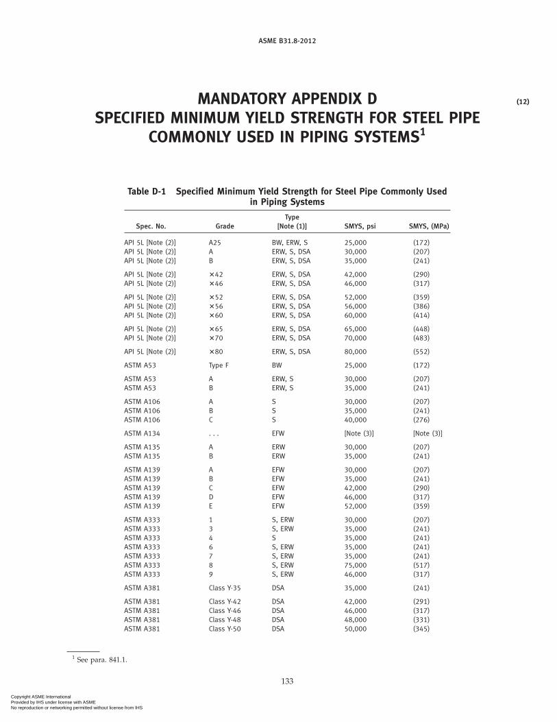
ASME B31.8-2012
MANDATORY APPENDIX DSPECIFIED MINIMUM YIELD STRENGTH FOR STEEL PIPE
COMMONLY USED IN PIPING SYSTEMS1
Table D-1 Specified Minimum Yield Strength for Steel Pipe Commonly Usedin Piping Systems
TypeSpec. No. Grade [Note (1)] SMYS, psi SMYS, (MPa)
API 5L [Note (2)] A25 BW, ERW, S 25,000 (172)API 5L [Note (2)] A ERW, S, DSA 30,000 (207)API 5L [Note (2)] B ERW, S, DSA 35,000 (241)
API 5L [Note (2)] �42 ERW, S, DSA 42,000 (290)API 5L [Note (2)] �46 ERW, S, DSA 46,000 (317)
API 5L [Note (2)] �52 ERW, S, DSA 52,000 (359)API 5L [Note (2)] �56 ERW, S, DSA 56,000 (386)API 5L [Note (2)] �60 ERW, S, DSA 60,000 (414)
API 5L [Note (2)] �65 ERW, S, DSA 65,000 (448)API 5L [Note (2)] �70 ERW, S, DSA 70,000 (483)
API 5L [Note (2)] �80 ERW, S, DSA 80,000 (552)
ASTM A53 Type F BW 25,000 (172)
ASTM A53 A ERW, S 30,000 (207)ASTM A53 B ERW, S 35,000 (241)
ASTM A106 A S 30,000 (207)ASTM A106 B S 35,000 (241)ASTM A106 C S 40,000 (276)
ASTM A134 . . . EFW [Note (3)] [Note (3)]
ASTM A135 A ERW 30,000 (207)ASTM A135 B ERW 35,000 (241)
ASTM A139 A EFW 30,000 (207)ASTM A139 B EFW 35,000 (241)ASTM A139 C EFW 42,000 (290)ASTM A139 D EFW 46,000 (317)ASTM A139 E EFW 52,000 (359)
ASTM A333 1 S, ERW 30,000 (207)ASTM A333 3 S, ERW 35,000 (241)ASTM A333 4 S 35,000 (241)ASTM A333 6 S, ERW 35,000 (241)ASTM A333 7 S, ERW 35,000 (241)ASTM A333 8 S, ERW 75,000 (517)ASTM A333 9 S, ERW 46,000 (317)
ASTM A381 Class Y-35 DSA 35,000 (241)
ASTM A381 Class Y-42 DSA 42,000 (291)ASTM A381 Class Y-46 DSA 46,000 (317)ASTM A381 Class Y-48 DSA 48,000 (331)ASTM A381 Class Y-50 DSA 50,000 (345)
1 See para. 841.1.
133
(12)
Copyright ASME International Provided by IHS under license with ASME No reproduction or networking permitted without license from IHS

ASME B31.8-2012
Table D-1 Specified Minimum Yield Strength for Steel Pipe Commonly Usedin Piping Systems (Cont’d)
TypeSpec. No. Grade [Note (1)] SMYS, psi SMYS, (MPa)
ASTM A381 Class Y-52 DSA 52,000 (359)ASTM A381 Class Y-56 DSA 56,000 (386)ASTM A381 Class Y-60 DSA 60,000 (414)
ASTM A381 Class Y-65 DSA 65,000 (448)
ASTM A984 35 ERW 35,000 (241)ASTM A984 50 ERW 50,000 (345)ASTM A984 60 ERW 60,000 (414)ASTM A984 70 ERW 70,000 (483)ASTM A984 80 ERW 80,000 (552)
ASTM A1005 35 DSA 35,000 (241)ASTM A1005 50 DSA 50,000 (345)ASTM A1005 60 DSA 60,000 (414)ASTM A1005 70 DSA 70,000 (483)ASTM A1005 80 DSA 80,000 (552)
ASTM A1006 35 LW 35,000 (241)ASTM A1006 50 LW 50,000 (345)ASTM A1006 60 LW 60,000 (414)ASTM A1006 70 LW 70,000 (483)ASTM A1006 80 LW 80,000 (552)
GENERAL NOTE: This table is not complete. For the minimum specified yield strength of other gradesand grades in other approved specifications, refer to the particular specification.
NOTES:(1) Abbreviations: BW p furnace buttwelded; DSA p double submerged-arc welded; EFW p electric
fusion welded; ERW p electric resistance welded; FW p flash welded; S p seamless; LW p laserwelded.
(2) Intermediate grades are available in API 5L.(3) See applicable plate specification for SMYS.
134
Copyright ASME International Provided by IHS under license with ASME No reproduction or networking permitted without license from IHS

ASME B31.8-2012
Table D-2 HDB Values forThermoplastic Materials
Plastic Pipe MaterialDesignation Long-Term Hydrostatic Strength(D2513) at 73°F, psi
PA 32312 (PA-11) 2,500PB 2110 2,000PE 2406 1,250PE 3408 1,600
PE 2606 1.250PE 2706 1.250PE 2708 1,250PE 3608 1,600
PE 3708 1,600PE 3710 1,600PE 4708 1,600PE 4710 1.600
PVC 1120 4,000PVC 1220 4,000PVC 2110 2,000PVC 2116 3,150
GENERAL NOTES:(a) Long-Term Hydrostatic Strength Values for Thermoplastic Pipes
Covered by ASTM D2513. The values apply only to materialsand pipes meeting all the requirements of the basic materialsand ASTM D2513. They are based on engineering test dataobtained in accordance with ASTM D1598 and analyzed inaccordance with ASTM D2837. A list of commercial compoundsmeeting these requirements is published yearly by the PlasticsPipe Institute.
(b) HDB Values for Reinforced Thermosetting Pipes Covered byASTM D2517. The value is established in accordance withASTM D2517. In the absence of an established HDB, the valueis 11,000 psi (75.8 MPa).
135
Copyright ASME International Provided by IHS under license with ASME No reproduction or networking permitted without license from IHS

ASME B31.8-2012
MANDATORY APPENDIX EFLEXIBILITY AND STRESS INTENSIFICATION FACTORS
Table E-1 begins on the following page.
136
Copyright ASME International Provided by IHS under license with ASME No reproduction or networking permitted without license from IHS

ASME B31.8-2012
Table E-1 Flexibility Factor, k, and Stress Intensification Factor, i
Stress IntensificationFactor, i [Notes (1) and (2)]Flexibility Flexibility
Factor, Out-plane, In-plane, Characteristic,Description k io ii h Sketch
Welding elbow or pipe bend 1.65h
0.75
h2⁄30.9
h2⁄3T R1
r22[Notes (1)–(5)]
Closely spaced miter bend [Notes(1), (2), (3), and (5)]
1.52
h5/60.9
h2/30.9
h2/3cot �2
Ts
r22
s < r2 (1 + tan � )
Single miter bend or widelyspaced miter bend 1.52
h5/60.9
h2/30.9
h2/31 + cot �2
Tr2s ≥ r2 (1 + tan � )
[Notes (1), (2), and (5)]
Welding tee per ASME B16.9 withro ≥ d⁄8 1
0.9
h2/33⁄4io +
1⁄4 4.4Tr2Tc ≥ 1.5 T
[Notes (1), (2), and (6)]
Reinforced fabricated tee withpad or saddle [Notes (1), (2), 1
0.9
h2/33⁄4 io +
1⁄4(T + 1⁄2 te)
5/2
T3/2 r2(7)–(9)]
Unreinforced fabricated tee1
0.9
h2/33⁄4 io +
1⁄4Tr2[Notes (1), (2), and (9)]
Extruded outletro ≥ 0.05d
10.9
h2/33⁄4 io +
1⁄4 �1 + ro
r2�Tr2Tc < 1.5 T
[Notes (1), (2), and (6)]
Welded-in contour insertro ≥ d⁄8 1
0.9
h2/33⁄4 io +
1⁄4 4.4Tr2Tc ≥ 1.5 T
[Notes (1), (2), and (10)]
Branch welded-on fitting (inte-grally reinforced) [Notes (1), 1
0.9
h2/30.9
h2/33.3
Tr2(2), (9), and (11)]
137
Copyright ASME International Provided by IHS under license with ASME No reproduction or networking permitted without license from IHS

ASME B31.8-2012
Table E-1 Flexibility Factor, k, and Stress Intensification Factor, i (Cont’d)
Flexibility Stress IntensificationFactor, Factor,
Description k i Sketch
Buttweld [Notes (1) and (12)]
1 1.0T ≥ 0.237 in. (6.02 mm),
�max. ≤ 1⁄16 in. (1.59 mm),and �avg/T ≤ 0.13
Buttweld [Notes (1) and (12)]
T ≥ 0.237 in. (6.02 mm),�max. ≤ 1⁄8 in. (3.18 mm), 1.9 max. or δ
T T
and �avg/T p any value 1 [0.9 + 2.7(�avg/T)],but not less than
1.0Buttweld [Notes (1) and (12)]
T ≤ 0.237 in. (6.02 mm),�max. ≤ 1⁄16 in. (1.59 mm),
and �avg/T ≤ 0.33
1 1.9 max. orTapered transition perASME B16.25 1.3 + 0.0036
Do
T+ 3.6
�
T[Note (1)]Do
T
1 2.0 max. or
Concentric reducer per 0.5 + 0.01� �Do2
T2 �1/2
ASME B16.9 [Notes (1) and(13)] Do2
α
Do1
T2
T1
Double-welded slip-on flange 1 1.2[Note (14)]
Socket welding flange or fit- 1 2.1 max or 2.1 T/Cx butting [Notes (14) and (15)] not less than 1.3
Lap joint flange (with 1 1.6ASME B16.9 lap joint stub)[Note (14)]
Threaded pipe joint or 1 2.3threaded flange [Note (14)]
Corrugated straight pipe, or 5 2.5corrugated or creased bend[Note (16)]
138
Copyright ASME International Provided by IHS under license with ASME No reproduction or networking permitted without license from IHS

ASME B31.8-2012
Table E-1 Flexibility Factor, k, and Stress Intensification Factor, i (Cont’d)
139
Copyright ASME International Provided by IHS under license with ASME No reproduction or networking permitted without license from IHS

ASME B31.8-2012
Table E-1 Flexibility Factor, k, and Stress Intensification Factor, i (Cont’d)
NOTES:(1) The nomenclature is as follows:
d poutside diameter of branch, in. (mm)R1 pbend radius of welding elbow or pipe bend, in. (mm)r0 p radius of curvature of external contoured portion of outlet, measured in the plane containing the axes of the header and
branch, in. (mm)r2 pmean radius of matching pipe, in. (mm)s pmiter spacing at centerline, in. (mm)T pnominal wall thickness of piping component, in. (mm)
p for elbows and miter bends, the nominal wall thickness of the fitting, in. (mm)p for welding tees, the nominal wall thickness of the matching pipe, in. (mm)p for fabricated tees, the nominal wall thickness of the run or header (provided that if thickness is greater than that of matchingpipe, increased thickness must be maintained for at least one run outside diameter to each side of the branch outside diame-ter), in. (mm)
Tc p the crotch thickness of tees, in. (mm)te ppad or saddle thickness, in. (mm)� p reducer cone angle, deg� pone-half angle between adjacent miter axes, deg
(2) The flexibility factor, k, applies to bending in any plane. The flexibility factors, k, and stress intensification factors, i, shall not be lessthan unity; factors for torsion equal unity. Both factors apply over the effective arc length (shown by heavy centerlines in thesketches) for curved and miter bends and to the intersection point for tees.The values of k and i can be read directly from Chart A by entering with the characteristic, h, computed from the formulas given.
(3) Where flanges are attached to one or both ends, the values of k and i shall be corrected by the factors, Cu, which can be readdirectly from Chart B, entering with the computed h.
(4) The designer is cautioned that cast buttwelded fittings may have considerably heavier walls than that of the pipe with which they areused. Large errors may be introduced unless the effect of these greater thicknesses is considered.
(5) In large diameter thin-wall elbows and bends, pressure can significantly affect the magnitudes of k and i. To correct values from thetable, divide k by
�1 + 6 �PEe� �r2T �
7/3
�R1r2�1/3
�divide i by
�1 + 3.25 �PEe� �r2T �
5/2
�R1r2�2/3
�where
Ee p cold modulus of elasticity, psi (MPa)P p gage pressure, psi (MPa)
(6) If the number of displacement cycles is less than 200, the radius and thickness limits specified need not be met. When the radiusand thickness limits are not met and the number of design cycles exceeds 200, the out-plane and in-plane stress intensification fac-tors shall be calculated as 1.12/h2/3 and (0.67/h2/3) + 1⁄4, respectively.
(7) When te > 11⁄2T, use h p 4.05T/r2.(8) The minimum value of the stress intensification factor shall be 1.2.(9) When the branch-to-run diameter ratio exceeds 0.5, but is less than 1.0, and the number of design displacement cycles exceeds
200, the out-plane and in-plane stress intensification factors shall be calculated as 1.8/h2/3 and (0.67/h2/3) + 1⁄4, respectively,unless the transition weld between the branch and run is blended to a smooth concave contour. If the transition weld is blended toa smooth concave contour, the stress intensification factors in the table still apply.
(10) If the number of displacement cycles is less than 200, the radius and thickness limits specified need not be met. When the radiusand thickness limits are not met and the number of design displacement cycles exceeds 200, the out-plane and in-plane stress inten-sification factors shall be calculated as 1.8/h2/3 and (0.67/h2/3) + 1⁄4, respectively.
(11) The designer must be satisfied that this fabrication has a pressure rating equivalent to straight pipe.(12) The stress intensification factors apply to girth butt welds between two items for which the wall thicknesses are between 0.875T and
1.10T for an axial distance of �Do T · Do and T are nominal outside diameter and nominal wall thickness, respectively. �avg is theaverage mismatch or offset.
140
Copyright ASME International Provided by IHS under license with ASME No reproduction or networking permitted without license from IHS

ASME B31.8-2012
Table E-1 Flexibility Factor, k, and Stress Intensification Factor, i (Cont’d)
NOTES: (Cont’d)(13) The equation applies only if the following conditions are met.
(a) Cone angle � does not exceed 60 deg, and the reducer is concentric.(b) The larger of Do1/T and Do2/T does not exceed 100.(c) The wall thickness is not less than T1 throughout the body of the reducer, except in and immediately adjacent to the cylindrical
portion on the small end, where the thickness shall not be less than T2.(14) For some flanged joints, leakage may occur at expansion stresses otherwise permitted herein. The moment to produce leakage of a
flanged joint with a gasket having no self-sealing characteristics can be estimated by the following equation:
ML p (C/4) (Sb Ab − PAp)
Ab p total area of flange bolts, in.2 (mm3)Ap p area to outside of gasket contact, in.2 (mm2)C p bolt circle, in. (mm)
ML p moment to produce flange leakage, in.-lb (mm·N)P p internal pressure, psi (MPa)
Sb p bolt stress, psi (MPa)(15) Cx is the fillet weld length. For unequal lengths, use the smaller leg for Cx.(16) Factors shown apply to bending. Flexibility factor for torsion equals 0.9.
141
Copyright ASME International Provided by IHS under license with ASME No reproduction or networking permitted without license from IHS

ASME B31.8-2012
MANDATORY APPENDIX FEXTRUDED HEADERS AND WELDED BRANCH CONNECTIONS1
F-1 EXTRUDED HEADERS
Definitions and limitations applicable to Figs. F-1through F-4 are as follows:
D p outside diameter of run, in. (mm)d p outside diameter of branch pipe, in. (mm)
Dc p corroded internal diameter of run, in. (mm)dc p corroded internal diameter of branch pipe,
in. (mm)Do p corroded internal diameter of extruded outlet
measured at the level of the outside surface ofrun, in. (mm)
ho p height of the extruded lip. This must be equalto or greater than ro, except as shown in limita-tion (b) of ro below, in. (mm).
L p height of the reinforcement zone, in. (mm)p 0.7�dT0
rl p half width of reinforcement zone (equal to Do),in. (mm)
ro p radius of curvature of external contoured por-tion of outlet measured in the plane containingthe axes of the run and branch, in. (mm). Thisis subject to the following limitations:
(a) Minimum Radius. This dimension shallnot be less than 0.05d (1.27d), except that onbranch diameters larger than 30 in. (762 mm),it need not exceed 1.50 in. (38.1 mm).
(b) Maximum Radius. For outlet pipe sizesNPS 8 (DN 200) and larger, this dimension shallnot exceed 0.10d + 0.50 in. (2.54d + 12.7 mm).For outlet pipe sizes smaller than NPS 8(DN 200), this dimension shall not be greaterthan 1.25 in. (31.75 mm).
(c) When the external contour contains morethan one radius, the radius on any arc sectorof approximately 45 deg shall meet the require-ments of (a) and (b) above.
(d) Machining shall not be employed tomeetthe above requirements.
Tb p actual thickness of branch wall, not includingcorrosion allowance, in. (mm)
tb p required thickness of branch pipe according tothe steel pipe design formula of para. 841.1.1,but not including any thickness for corrosion,in. (mm)
1 See para. 831.6.
142
To p corroded finished thickness of extruded outletmeasured at a height equal to ro above theoutside surface of the run, in. (mm)
Tr p actual thickness of the run wall, not includingthe corrosion allowance, in. (mm)
tr p required thickness of the run according to thesteel pipe design formula para. 841.1.1, but notincluding any allowance for corrosion orunder-thickness tolerance, in. (mm)
F-2 EXAMPLES ILLUSTRATING THE APPLICATIONOF THE RULES FOR REINFORCEMENT OFWELDED BRANCH CONNECTIONS
F-2.1 Example 1
An NPS 8 outlet is welded to an NPS 24 header. Theheader material is API 5LX 46 with a 0.312-in. wall. Theoutlet is API 5L Grade B (Seamless) Schedule 40 with a0.322-in. wall. The working pressure is 650 psig. Thefabrication is in Location Class 1. Using para. 841.1, thejoint efficiency is 1.00. The temperature is 100°F. Designfactors F p 0.60, E p 1.00, and T p 1.00. For dimensions,see Fig. F-5.
F-2.1.1 Header. Nominal wall thickness required:
t pPD
2 SFETp
650 � 242 � 46,000 � 0.60 � 1.00 � 1.00
p 0.283 in.
Excess thickness in header wall:
H − t p 0.312 − 0.283 p 0.029 in.
F-2.1.2 Outlet. Nominal wall thickness required:
tb p650 � 8.625
2 � 35,000 � 0.60 � 1.00 � 1.00p 0.133 in.
Excess thickness in outlet wall:
B − tb p 0.322 − 0.133 p 0.189 in.
d p inside diameter of opening p 8.625 − 2 � 0.322p 7.981 in.
F-2.1.3 Reinforcement Required
AR p dt p 7.981 � 0.283 p 2.259 in.2
Copyright ASME International Provided by IHS under license with ASME No reproduction or networking permitted without license from IHS

ASME B31.8-2012
F-2.1.4 Reinforcement Provided by Header
A1 p (H − t) d p 0.029 � 7.981 p 0.231 in.2
F-2.1.5 Effective Area in Outlet
Height L p 21/2 B + M (assume 1/4-in. pad)p (21/2 � 0.322) + 0.25 p 1.055 in.
or L p 21/2H p 2.5 � 0.312 p 0.780 in. Use L p 0.780 in.
A2 p 2 (B − tb) L p 2 � 0.189 � 0.780p 0.295 in.2
This must be multiplied by 35,000/46,000 [seepara. 831.4.1(f)].
Effective A′2 p 0.295 �35,00046,000
p 0.224 in.2
Required area:
A3 p AR − A1 − A ′2p 2.259 − 0.231 − 0.224 p 1.804 in.2
Use a reinforced plate that is 0.250 in. thick (minimumpracticable) � 15.5 in. in diameter.
Area p (15.500 − 8.625) � 0.250 p 1.719 in.2
Fillet welds (assuming two 1⁄4-in. welds each side):
1/2 (0.25 � 0.25) � 4 p 0.125 in.2
Total A3 provided p 1.844 in.2
See also Fig. F-6.
F-2.1M Example 1M
A DN 200 outlet is welded to a DN 600 header. Theheader material is 317.2 MPa with a 7.92-mm wall. Theoutlet is 241.3 MPa (Seamless) with a 8.18 mm wall.The working pressure is 4.48 MPa. The fabrication is inLocation Class 1. Using para. 841.1, the joint efficiencyis 1.00. The temperature is 37.8°C. Design factors F p0.60, E p 1.00, and T p 1.00. For dimensions, see Fig. F-5.
F-2.1.1M Header. Nominal wall thickness required:
t pPD
2SFETp
4.48 � 609.62 � 317.16 � 0.60 � 1.00 � 1.00
p 7.178 mm
Excess thickness in header wall:
H − t p 7.925 − 7.178 p 0.747 mm
F-2.1.2M Outlet. Nominal wall thickness required:
tb p4.48 � 219.1
2 � 241.32 � 0.60 � 1.00 � 1.00p 3.390 mm
143
Excess thickness in outlet wall:
B − tb p 8.179 − 3.390 p 4.788 mm
d p inside diameter of opening p 219.08 − 2 � 8.179p 202.72 mm
F-2.1.3M Reinforcement Required
AR p dt p 202.72 � 7.178 p 1 455.2 mm2
F-2.1.4M Reinforcement Provided by Header
A1 p (H − t) d p 0.747 � 202.72 p 151.34 mm2
F-2.1.5M Effective Area in Outlet
Height L p 21/2 B + M (assume 6.35 mm pad)p (21/2 � 8.179) + 6.35 p 26.797 mm
or L p 21/2H p 2.5 � 7.92 p 19.812 mm. Use L p19.812 mm
A2 p 2 (B − tb) L p 2 � 4.788 � 19.812p 189.73 mm2
This must be multiplied by 241.3/317.2 [seepara. 831.4.1(f)].
Effective A′2 p 189.73 �241.3317.2
p 144.36 mm2
Required area:
A3 p AR − A1 − A′2p 1 455.2 − 151.34 − 144.36 p 1 159.5 mm2
Use a reinforced plate that is 6.35mm thick (minimumpracticable) � 393.7 mm in diameter.
Area p (393.7 − 219.1) � 6.35 p 1 108.9 mm2
Fillet welds (assuming two 6.35 mm welds each side):
1/2 (6.35 � 6.35) � 4 p 80.65 mm2
Total A3 provided p 1 189.5 mm2
See also Fig. F-6.
F-2.2 Example 2
An NPS 16 outlet is welded to an NPS 24 header. Theheader material is API 5LX 46 with a 0.312-in. wall. Theoutlet is API 5L Grade B (Seamless) Schedule 20 with a0.312-in. wall. The working pressure is 650 psig. Thefabrication is in Location Class 1. By para. 831.4.2, thereinforcement must be of the complete encirclementtype. Using para. 841.1, the joint efficiency is 1.00. Thetemperature is 100°F. Design factors F p 0.60, E p 1.00,and T p 1.00. For dimensions, see Fig. F-7.
F-2.2.1 Header. Nominal wall thickness required:
t pPD
2 SFETp
650 � 242 � 46,000 � 0.60 � 1.00 � 1.00
p 0.283 in.
Copyright ASME International Provided by IHS under license with ASME No reproduction or networking permitted without license from IHS

ASME B31.8-2012
Excess thickness in header wall:
H − t p 0.312 − 0.283 p 0.029 in.
F-2.2.2 Outlet. Nominal wall thickness required:
tb p650 � 16
2 � 35,000 � 0.60 � 1.00 � 1.00p 0.248 in.
Excess thickness in outlet wall:
B − tb p 0.312 − 0.248 p 0.064 in.
d p inside diameter of opening p 16.000 − 2 � 0.312p 15.376 in.
F-2.2.3 Reinforcement Required
AR p dt p 15.376 � 0.283 p 4.351 in.2
F-2.2.4 Reinforcement Provided
A1 p (H − t) d p 0.029 � 15.376 p 0.446 in.2
F-2.2.5 Effective Area in Outlet
Height L p 21/2 B + M (assume 5/16-in. plate)p (2.5 � 0.312) + 0.312 p 1.092 in.
or
L p 21/2H p 2.5 � 0.312 p 0.780 in. Use L p 0.780 in.
A2 p 2 (B − tb) L p 2 � 0.064 � 0.780p 0.100 in.2
This must be multiplied by 35,000/46,000 [seepara. 831.4.1(f)].
Effective A′2 p 0.100 � 35,000/46,000 p 0.076 in.2
Required area:
A3 p AR − A1 − A′2p 4.351 − 0.446 − 0.076 p 3.829 in.2
Approximate required thickness of reinforcement:
3.829 � (30 − 16) p 0.274 in.
Use a 0.312-in. plate minimum required length(neglecting welds):
3.829 � 0.312 p 12.272 in.
16 + 12.272 p 29 in. (rounded to the next higher wholenumber)
Use a plate that is 29 in. long:
Area p 0.312 � (29 − 16) p 4.056 in.2
144
Two 1⁄4-in. welds to outlet:
1/2 � (0.25 � 0.25) � 2 p 0.063 in.2
Total A3 provided p 4.119 in.2
The use of end welds is optional (see Fig. I-3).
F-2.2M Example 2M
A DN 400 outlet is welded to an DN 600 header. Theheader material is 317.2 MPa with a 7.92 mm wall. Theoutlet is 241.3 MPa (Seamless) with a 7.92 mm wall.The working pressure is 4.48 MPa. The fabrication is inLocation Class 1. By para. 841.4.2, the reinforcementmust be of the complete encirclement type. Usingpara. 841.1, the joint efficiency is 1.00. The temperatureis 37.8°C. Design factors F p 0.60, E p 1.00, andT p 1.00. For dimensions, see Fig. F-7.
F-2.2.1M Header. Nominal wall thickness required:
t pPD
2 SFETp
4.48 � 609.62 � 317.16 � 0.60 � 1.00 � 1.00
p 7.178 mm
Excess thickness in header wall:
H − t p 7.925 − 7.178 p 0.747 mm
F-2.2.2M Outlet. Nominal wall thickness required:
tb p4.48 � 406.4
2 � 241.32 � 0.60 � 1.00 � 1.00p 6.290 mm
Excess thickness in outlet wall:
B − tb p 7.925 − 6.290 p 1.635 mm
d p inside diameter of opening p 406.4 − 2 � 7.925p 390.55 mm
F-2.2.3M Reinforcement Required
AR p dt p 390.55 � 7.178 p 2 803.5 mm2
F-2.2.4M Reinforcement Provided
A1 p (H − t) d p 0.747 � 390.55 p 291.56 mm2
F-2.2.5M Effective Area in Outlet
Height L p 21/2 B + M (assume 7.94 mm plate)p (2.5 � 7.92) + 7.94 p 27.75 mm
or
L p 21/2H p 2.5 � 7.92 p 19.812 mm. Use L p 19.812 in.
A2 p 2 (B − tb) L p 2 � 1.635 � 19.812p 64.80 mm2
This must be multiplied by 241.3/317.2 [seepara. 831.4.1(f)].
Copyright ASME International Provided by IHS under license with ASME No reproduction or networking permitted without license from IHS

ASME B31.8-2012
Effective A′2 p 64.80 � 241.3/317.2 p 49.30 mm2
Required area:
A3 p AR − A1 − A′2p 2 803.5 − 291.56 − 49.30 p 2 462.6 mm2
Approximate required thickness of reinforcement:
2 462.6 � (762 − 406.4) p 6.925 mm
Use a 7.92 mm plate minimum required length(neglecting welds):
3.829 � 0.312 p 12.272 in.
145
406.4 + 310.75 p 736.6 mm (rounded to the next higherwhole number in customaryunits, i.e., equivalent to 29 in.)
Use a plate that is 736.6 mm long:
Area p 7.92 � (736.6 − 406.4) p 2616.8 mm2
Two 6.35 mm welds to outlet:
1/2 � (0.25 � 0.25) � 2 p 40.32 mm2
Total A3 provided p 2 657.1 mm2
The use of end welds is optional (see Fig. I-3).
Copyright ASME International Provided by IHS under license with ASME No reproduction or networking permitted without license from IHS

ASME B31.8-2012
Fig. F-1
Fig. F-2
GENERAL NOTE: Sketch to show method of establishing To when the taper encroaches on the crotch radius.
Fig. F-3
146
Copyright ASME International Provided by IHS under license with ASME No reproduction or networking permitted without license from IHS

ASME B31.8-2012
Fig. F-4
147
Copyright ASME International Provided by IHS under license with ASME No reproduction or networking permitted without license from IHS

ASME B31.8-2012
Fig. F-5 Rules for Reinforcement of Welded Branch Connections
148
Copyright ASME International Provided by IHS under license with ASME No reproduction or networking permitted without license from IHS

ASME B31.8-2012
Fig. F-6
Fig. F-7
149
Copyright ASME International Provided by IHS under license with ASME No reproduction or networking permitted without license from IHS

ASME B31.8-2012
MANDATORY APPENDIX GTESTING OF WELDERS LIMITED TO WORK ON LINES
OPERATING AT HOOP STRESSES OF LESS THAN 20% OF THESPECIFIED MINIMUM YIELD STRENGTH1
G-1 TEST PROCEDURES
(a) An initial test shall qualify a welder for work.Thereafter, the welder’s work shall be checked either byrequalification at 1-yr intervals or by cutting out andtesting production work at least every 6 mo.
(b) The test may be made on pipe of any diameterNPS 12 (DN 300) or smaller. The test weld shall be madewith the pipe in a horizontal fixed position so that thetest weld includes at least one section of overhead posi-tion welding.
(c) The beveling, root opening, and other details mustconform to the procedure specification under which thewelder is qualified.
(d) The test weld shall be cut into four coupons andsubjected to the root bend test. If as a result of this test,a crack develops in the weld material or between theweld and base metal more than 1⁄8 in. (3.2 mm) long inany direction, this shall be cause for rejection. Cracksoccurring on the corner of the specimen during testingshall not be considered. If not more than one coupon isrejected, the weld is to be considered acceptable.
(e) Welders who are to make welded service line con-nections to mains shall be required to pass the followingtests satisfactorily:
(1) Weld a service line connection fitting to a pipesection having the same diameter as a typical main. Thisweld shall be made in the same position as this type ofweld is made in the field.
(2) The weld shall be tested by attempting to breakthe fitting off the run pipe by any available means(knocking it off).
A sample shall be rejected if the broken weld at thejunction of the fitting and run pipe shows incompletefusion, overlap, or poor penetration.
1 See para. 823.1.
150
(f) For the periodic checking of welders who workon small service lines only [NPS 2 (DN 50) or smallerin diameter], the following special field test may beemployed. This test should not be used as a substitutefor the original qualifying test.
Two sample welds made by the welder under testshall be taken from steel service line. Each sample shallbe cut 8 in. (200mm) longwith theweld located approxi-mately in the center. One sample shall have the endsflattened and the entire joint subjected to the tensilestrength test. Failure must be in the parent metal andnot adjacent to or in the weld metal to be acceptable.The second sample shall be centered in the guided bendtesting machine and bent to the contour of the die fora distance of 2 in. (50 mm) on each side of the weld.The sample to be acceptable must show no breaks orcracks after removal from the bending machine.
When a tensile strength testing machine is not avail-able, two bend test samples will be acceptable in lieuof one tension and one bending test.
(g) Tests for Copper Joints. Personnel who are to workon copper piping should pass the following testsatisfactorily.
A brazed or soldered copper bell joint should be madeon any size of copper pipe used, with the axis of thepipe stationary in the horizontal position. The joint sowelded is to be sawed open longitudinally at the top ofthe pipe (the top being the uppermost point on thecircumstance at time joint is brazed). The joint shouldbe spread apart for examination. The bell end of thejoint must be completely bonded. The spigot end ofthe joint must give evidence that the brazing alloy hasreached at least 75% of the total area of the telescopedsurfaces. At least 50% of the length at the top of thejoint must be joined.
(h) Records shall be kept of the original tests and allsubsequent tests conducted on the work of each welder.
Copyright ASME International Provided by IHS under license with ASME No reproduction or networking permitted without license from IHS

ASME B31.8-2012
MANDATORY APPENDIX HFLATTENING TEST FOR PIPE1
H-1 TEST PROCEDURES
(a) The flattening test shall be made on standardweight and extra strong pipe over NPS 2 (DN 50). Itshall not be required for double extra strong pipe.
(b) For a lap-welded and buttwelded pipe, the testsection shall be 4 in. to 6 in. (100 mm to 150 mm) inlength, and the weld shall be located 45 deg from theline of direction of the applied force.
(c) For electric-resistance welded pipe, both crop endsfrom each length of pipe shall be flattened betweenparallel plates with the weld at the point of maximumbending until the opposite walls of the pipe meet. Noopening in the weld shall take place until the distancebetween the plates is less than two-thirds of the originaloutside diameter of the pipe. No cracks or breaks in themetal other than in theweld shall occur until the distancebetween the plates is less than one-third of the originaloutside diameter of the pipe, but in no case less thanfive times the thickness of the pipe wall. Evidence oflamination or burnt material shall not develop duringthe entire flattening process, and theweld shall not showinjurious defects.
(d) For seamless pipe the test section shall be not lessthan 21⁄2 in. (64 mm) in length.
1 See para. 817.1.3(b).
151
(e) The test shall consist of flattening a section of pipebetween parallel plates until the opposite walls meet.For welded pipe, no opening in the weld shall take placeuntil the distance between the plates is less than three-fourths of the original outside diameter for buttweldedpipe, and two-thirds of the outside diameter for lap-welded and electric-resistance welded pipes. No cracksor breaks in the metal other than in the weld shall occuruntil the distance between the plates is less than three-fifths of the outside diameter for buttwelded pipe, andone-third of the outside diameter for lap-welded andelectric-resistance welded (Grades A and B) pipes. Forseamless (Grades A and B) pipe, no breaks or cracks inthe metal shall occur until the distance between theplates is less than that shown below:
H p(1 + e) te + t/D
whereD p actual outside diameter of pipes, in. [2.375 in.
(60.33 mm) nominal]e p deformation per unit length (constant for a
given grade of steel, 0.09 for Grade A and 0.07for Grade B)
H p distance between flattening plates, in. (mm)t p nominal wall thickness of pipe, in. (mm)
Copyright ASME International Provided by IHS under license with ASME No reproduction or networking permitted without license from IHS

ASME B31.8-2012
MANDATORY APPENDIX IEND PREPARATIONS FOR BUTTWELDING
I-1 EXPLANATORY NOTES
I-1.1 General
This Mandatory Appendix applies to end preparationfor buttwelding sections havingunequal thicknesses andunequal specifiedminimum yield strengths (see Figs. I-1through I-4).
(a) The sketches in Fig. I-5 illustrate acceptable prepa-rations for joining pipe ends by buttwelding for materi-als having unequal wall thicknesses and/or withunequal strengths (specified minimum yield strength).
(b) The thickness of the sections to be joined beyondthe joint design area shall comply with the designrequirements of this Code.
(c) When the specified minimum yield strengths ofthe sections to be joined are unequal, the deposited weldmetal shall have mechanical properties at least equal tothose of the section having the higher strength.
(d) The transition between ends of unequal thicknessmay be accomplished by taper or welding as illustratedor by means of a prefabricated transition ring.
(e) Sharp notches or grooves at the edge of the weldwhere it joins a slanted surface shall be avoided.
(f) For joining unequal thicknesses of equal specifiedminimum yield strengths, the rules given herein apply,except there is no minimum angle limit to the taper.
(g) The maximum thickness, tD, for design purposesshall not be greater than 1.5t.
I-1.2 Unequal Internal Diameters
(a) For piping to operate at hoop stresses of less than20% of specified minimum yield strength, if the nominalwall thicknesses of the adjoining ends do not vary morethan 1⁄8 in. (3.2 mm), no special treatment is necessaryprovided adequate penetration and bond is accom-plished in welding. If the offset is greater than 1⁄8 in.(3.2 mm), the following paragraphs will apply.
(b) For Hoop Stress Levels 20% or More of the SpecifiedMinimum Yield Strength
(1) If the nominal wall thickness of the adjoiningends does not varymore than 3⁄32 in. (2.38mm), no special
152
treatment is necessary, provided full penetration andbond is accomplished in welding. See sketch (a) ofFig. I-5.
(2) Where the nominal internal offset is greater than3⁄32 in. (2.38 mm) and there is no access to the inside ofthe pipe for welding, the transition must be made by ataper cut on the inside end of the thicker section. Seesketch (b) of Fig. I-5. The taper angle shall be not greaterthan 30 deg nor less than 14 deg.
(3) Where the nominal internal offset is more than3⁄32 in. (2.38mm) but does not exceed one-half the thinnersection, and there is access to the inside of the pipe forwelding, the transition may be made with a taperedweld as shown in sketch (c) of Fig. I-5. The land on thethicker section must be equal to the offset plus the landon abutting section.
(4) Where the nominal internal offset is more thanone-half the thinner section and there is access to theinside of the pipe for welding, the transition may bemade with a taper cut on the inside end of the thickersection as shown in sketch (b) of Fig. I-5, or by a combina-tion taper weld to one-half the thinner section and ataper cut from that point as shown in sketch (d) ofFig. I-5.
I-1.3 Unequal External Diameters
(a) Where the external offset does not exceed one-half the thinner section, the transition may be made bywelding as shown by sketch (e) of Fig. I-5, provided theangle of rise of the weld surface does not exceed 30 degand both bevel edges are properly fused.
(b) Where there is an external offset exceeding one-half the thinner section, that portion of the offset over1⁄2t shall be tapered as shown in sketch (f) of Fig. I-5.
I-1.4 Unequal Internal and External Diameters
Where there is both an internal and an external offset,the joint design shall be a combination of sketches (a)through (f) of Fig. I-5, i.e., sketch (g). Particular attentionmust be paid to proper alignment under these condi-tions. See also Fig. I-6 and Tables I-1 and I-1M.
Copyright ASME International Provided by IHS under license with ASME No reproduction or networking permitted without license from IHS

ASME B31.8-2012
Fig. I-1 Welding Details for Openings Without Reinforcement Other Than That inHeader and Branch Walls
GENERAL NOTES:(a) When a welding saddle is used, it shall be inserted over this type of connection.(b) W1 p 3B⁄8, but not less than
1⁄4 in. (6.35 mm).(c) N p 1⁄16 in. (1.59 mm) min.,
1⁄8 in. (3.18 mm) max., unless back welded or backing strip is used.
Fig. I-2 Welding Details for Openings With Localized-Type Reinforcement
GENERAL NOTES:(a) All welds to have equal leg dimensions, and a minimum throat p 0.707 � leg dimension.(b) If M is thicker than H, the reinforcing member shall be tapered down to the header wall thickness.(c) Provide hole in reinforcement to reveal leakage in buried welds and to provide venting during welding and heat treatment
[see para. 831.4.1(h)].
153
Copyright ASME International Provided by IHS under license with ASME No reproduction or networking permitted without license from IHS

ASME B31.8-2012
Fig. I-3 Welding Details for Openings With Complete Encirclement Types of Reinforcement
NOTES:(1) Since fluid pressure is exerted on both sides of pipe metal under tee, the pipe metal does not provide reinforcement.(2) Provide hole in reinforcement to reveal leakage in buried welds and to provide venting during welding and heat treatment
[see para. 831.4.1(h)]. Not required for tee type.
154
Copyright ASME International Provided by IHS under license with ASME No reproduction or networking permitted without license from IHS

ASME B31.8-2012
Fig. I-3.1 Pressurized Hot Tap Tee Reinforcing Sleeve End Fillet Weld Design
Gap
End face � 1.4 times calculated hoopthickness of sleeve (max.), if required
Pressurized hot tapping teereinforcing sleeve
Pipe wall thickness � t
Fillet weld leg � 1.0t � gap to 1.4t + gap
Effective weld throat � 0.7t to 1.0t
Chamfer/taper � 45 deg min. (approx.)
155
Copyright ASME International Provided by IHS under license with ASME No reproduction or networking permitted without license from IHS

ASME B31.8-2012
Fig.
I-4
Acce
ptab
leCo
mbi
nati
ons
ofPi
peEn
dPr
epar
atio
ns
156
Copyright ASME International Provided by IHS under license with ASME No reproduction or networking permitted without license from IHS

ASME B31.8-2012
Fig. I-5 Acceptable Design for Unequal Wall Thickness
NOTE:(1) No minimum when materials joined have equal specified minimum yield strengths.
157
Copyright ASME International Provided by IHS under license with ASME No reproduction or networking permitted without license from IHS

ASME B31.8-2012
Fig. I-6 Recommended Attachment Details of Flanges
158
Copyright ASME International Provided by IHS under license with ASME No reproduction or networking permitted without license from IHS

ASME B31.8-2012
Table I-1 Lightweight Flanges
Drilling TemplateInside OutsideNominal Outside Diameter, Length Diameter Number Diameter Diameter Approx. Weight
Pipe Diameter, Thickness, B of Hub, of Hub, of and Length of Bolt Each,Size A T [Note (1)] L E Bolts of Bolts Circle lb
6 11 9⁄16 6.72 11⁄4 79⁄16 8 3⁄4 � 21⁄4 91⁄2 138 131⁄2
9⁄16 8.72 11⁄4 911⁄16 8 3⁄4 � 21⁄4 113⁄4 1810 16 11⁄16 10.88 11⁄4 12 12 7⁄8 � 21⁄2 141⁄4 2612 19 11⁄16 12.88 11⁄4 143⁄8 12 7⁄8 � 21⁄2 17 4214 21 3⁄4 14.14 11⁄4 153⁄4 12 1 � 23⁄4 183⁄4 44
16 231⁄23⁄4 16.16 11⁄4 18 16 1 � 23⁄4 211⁄4 58
18 25 3⁄4 18.18 11⁄4 197⁄8 16 11⁄8 � 3 223⁄4 5920 271⁄2
3⁄4 20.20 11⁄4 22 20 11⁄8 � 3 25 6922 291⁄2 1 22.22 13⁄4 241⁄4 20 11⁄4 � 31⁄2 271⁄4 76
24 32 1 24.25 13⁄4 261⁄8 20 11⁄4 � 31⁄2 291⁄2 11326 341⁄4 1 26.25 13⁄4 281⁄2 24 11⁄4 � 31⁄2 313⁄4 12628 361⁄2 1 28.25 13⁄4 301⁄2 28 11⁄4 � 31⁄2 34 13930 383⁄4 1 30.25 13⁄4 321⁄2 28 11⁄4 � 31⁄2 36 152
32 413⁄4 11⁄8 32.25 13⁄4 343⁄4 28 11⁄2 � 4 381⁄2 20634 433⁄4 11⁄8 34.25 13⁄4 363⁄4 32 11⁄2 � 4 401⁄2 21736 46 11⁄8 . . . 13⁄4 383⁄4 32 11⁄2 � 4 423⁄4 23438 483⁄4 11⁄8 . . . 13⁄4 403⁄4 32 11⁄2 � 4 451⁄4 264
40 503⁄4 11⁄8 . . . 13⁄4 43 36 11⁄2 � 4 471⁄4 28042 53 11⁄4 . . . 13⁄4 45 36 11⁄2 � 41⁄4 491⁄2 32844 551⁄4 11⁄4 . . . 21⁄4 47 40 11⁄2 � 41⁄4 513⁄4 34946 571⁄4 11⁄4 . . . 21⁄4 49 40 11⁄2 � 41⁄4 533⁄4 363
48 591⁄2 13⁄8 . . . 21⁄2 51 44 11⁄2 � 41⁄2 56 42650 613⁄4 13⁄8 . . . 21⁄2 53 44 13⁄4 � 43⁄4 581⁄4 45152 64 13⁄8 . . . 21⁄2 55 44 13⁄4 � 43⁄4 601⁄2 47754 661⁄4 13⁄8 . . . 21⁄2 57 44 13⁄4 � 43⁄4 623⁄4 504
60 73 11⁄2 . . . 23⁄4 63 52 13⁄4 � 5 691⁄4 64366 80 11⁄2 . . . 23⁄4 69 52 13⁄4 � 5 76 75472 861⁄2 11⁄2 . . . 23⁄4 75 60 13⁄4 � 5 821⁄2 846
GENERAL NOTES:(a) Lightweight flanges are flat-faced and designed for use with full-face gasket or asbestos sheet gasket extending to the bolt holes.(b) Maximum pressure for lightweight flanges is 25 psi; drilling is the same as Class 125 standard.(c) This table encompasses forged and rolled steel; for further information, refer to ASTM A105.(d) All dimensions in the table are in inches, unless otherwise noted.
NOTE:(1) For nominal pipe sizes 36 through 72, the inside diameter, B, shall be as specified by the purchaser.
159
Copyright ASME International Provided by IHS under license with ASME No reproduction or networking permitted without license from IHS

ASME B31.8-2012
Table I-1M Lightweight Flanges (Metric Dimensions)
Drilling TemplateInside OutsideNominal Outside Diameter, Length Diameter Number Diameter Diameter Approx. Weight
Pipe Diameter, Thickness, B of Hub, of Hub, of and Length of Bolt Each,Size A T [Note (1)] L E Bolts of Bolts Circle kg
DN 150 279.4 14.29 170.69 31.75 192.09 8 19.05 � 57.15 241.3 5.9DN 200 342.9 14.29 221.49 31.75 246.06 8 19.05 � 57.15 298.5 8.2DN 250 406.4 17.46 276.35 31.75 304.80 12 22.23 � 63.50 362.0 11.8DN 300 482.6 17.46 327.15 31.75 365.13 12 22.23 � 63.50 431.8 19.1
DN 350 533.4 19.05 359.16 31.75 400.05 12 25.40 � 69.85 476.3 20.0DN 400 596.9 19.05 410.46 31.75 457.20 16 25.40 � 69.85 539.8 26.3DN 450 635.0 19.05 461.77 31.75 504.83 16 28.58 � 76.20 577.9 26.8DN 500 698.5 19.05 513.08 31.75 558.80 20 28.58 � 76.20 635.0 31.3
DN 550 749.3 25.40 564.39 44.45 615.95 20 31.75 � 88.90 692.2 34.5DN 600 812.8 25.40 615.95 44.45 663.58 20 31.75 � 88.90 749.3 51.3DN 650 870.0 25.40 666.75 44.45 723.90 24 31.75 � 88.90 806.5 57.2DN 700 927.1 25.40 717.55 44.45 774.70 28 31.75 � 88.90 863.6 63.0
DN 750 984.3 25.40 768.35 44.45 825.50 28 31.75 � 88.90 914.4 68.9DN 800 1 060.5 28.58 819.15 44.45 882.65 28 38.10 � 101.60 977.9 93.4DN 850 1 111.3 28.58 869.95 44.45 933.45 32 38.10 � 101.60 1 028.7 98.4DN 900 1 168.4 28.58 . . . 44.45 984.25 32 38.10 � 101.60 1 085.9 106.1
DN 950 1 238.3 28.58 . . . 44.45 1 035.05 32 38.10 � 101.60 1 149.4 119.7DN 1000 1 289.1 28.58 . . . 44.45 1 092.20 36 38.10 � 101.60 1 200.2 127.0DN 1050 1 346.2 31.75 . . . 44.45 1 143.00 36 38.10 � 107.95 1 257.3 148.8DN 1100 1 403.4 31.75 . . . 57.15 1 193.80 40 38.10 � 107.95 1 314.5 158.3
DN 1150 1 454.2 31.75 . . . 57.15 1 244.60 40 38.10 � 107.95 1 365.3 164.7DN 1200 1 511.3 34.93 . . . 63.50 1 295.40 44 38.10 � 114.30 1 422.4 193.2DN 1250 1 568.5 34.93 . . . 63.50 1 346.20 44 44.45 � 120.65 1 479.6 204.6DN 1300 1 625.6 34.93 . . . 63.50 1 397.00 44 44.45 � 120.65 1 536.7 216.4
DN 1350 1 682.8 34.93 . . . 63.50 1 447.80 44 44.45 � 120.65 1 593.9 228.6DN 1500 1 854.2 38.10 . . . 69.85 1 600.20 52 44.45 � 127.00 1 759.0 291.7DN 1650 2 032.0 38.10 . . . 69.85 1 752.60 52 44.45 � 127.00 1 930.4 342.0DN 1800 2 197.1 38.10 . . . 69.85 1 905.00 60 44.45 � 127.00 2 095.5 383.7
GENERAL NOTES:(a) Lightweight flanges are flat-faced and designed for use with full-face gasket or asbestos sheet gasket extending to the bolt holes.(b) Maximum pressure for lightweight flanges is 172 kPa; drilling is the same as Class 125 standard.(c) This table encompasses forged and rolled steel; for further information, refer to ASTM A105.(d) All dimensions in the table are in mm, unless otherwise noted.
NOTE:(1) For nominal pipe sizes DN 900 through DN 1800, the inside diameter, B, shall be as specified by the purchaser.
160
Copyright ASME International Provided by IHS under license with ASME No reproduction or networking permitted without license from IHS

ASME B31.8-2012
NONMANDATORY APPENDIX JCOMMONLY USED CONVERSION FACTORS1
Table J-1 Commonly Used Conversion Factors
Quantity Conversion Factor
Plane angle deg to rad 1.745 329E−02
Length in. to m 2.54E−02 [Note (1)]ft to m 3.048E−01 [Note (1)]mile to m 1.609 344E+03 [Note (1)]
Area in.2 to m2 6.451 600E−04 [Note (1)]ft2 to m2 9.290 304E−02 [Note (1)]
Volume ft3 to m3 2.831 685E−02U.S. gal to m3 3.785 412E−03in.3 to m3 1.638 706E−05oz (fluid, U.S.) to m3 2.957 353E−05liter to m3 1.000 000E−03
Velocity ft/min to m/s 5.08E−03 [Note (1)]ft/sec to m/s 3.048E−01 [Note (1)]km/h to m/s 2.777 778E−01mi/hr to m/s 4.470 4E−01 [Note (1)]mi/hr to km/h 1.609 344E+00 [Note (1)]
Mass oz (avoir) to kg 2.834 952E−02lb (avoir) to kg 4.535 924E−01slug to kg 1.459 390E+01
Acceleration ft/sec2 to m/s2 3.048E−01 [Note (1)]std. grav. to m/s2 9.806 65E+00 [Note (1)]
Force kgf to N 9.806 65E+00 [Note (1)]lbf to N 4.448 222E+00poundal to N 1.382 550E−01
Bending, torque kgf·m to N·m 9.806 65E+00 [Note (1)]lbf-in. to N·m 1.129 848E−01lbf-ft to N·m 1.355 818E+00
Pressure [Note (1)] psi to bar 6.894 757E−02Pa to bar 1.000E−05kPa to bar 1.000E−02
1 Extracted partially from ASME SI-1.
161
Copyright ASME International Provided by IHS under license with ASME No reproduction or networking permitted without license from IHS

ASME B31.8-2012
Table J-1 Commonly Used Conversion Factors (Cont’d)
Quantity Conversion Factor
Stress [Note (1)] psi to MPa 6.894 757E−03kips/in.2 to MPa 6.894 757E+00N/mm2 to MPa 1.000E+00
Energy, work Btu (IT) to J 1.055 056E+03Calorie (IT) to J 4.186 8E+00 [Note (1)]lbf-ft to J 1.355 818E+00
Power hp (550 ft lbf/sec) to W 7.456 999E+02
Temperature [Note (1)] °C to K tK p tC + 273.15°F to K tK p (tF + 459.67)/1.8°F to °C tC p (tF − 32)/1.8
Temperature °C to K 1.0E+00 [Note (1)]interval °F to K or °C 5.555 556E−01
GENERAL NOTES:(a) For other commonly used conversion factors, refer to IEEE/ASTM SI 10.(b) The factors are written as a number greater than one and less than 10 with six or less decimal
places. The number is followed by the letter E (for exponent), a plus or minus symbol, and two dig-its that indicate the power of 10 by which the number must be multiplied to obtain the correctvalue. For example,
1.745 329E−02 is 1.745 329 � 10−2 or 0.017 453 29
NOTE:(1) Relationships are exact in terms of the base units.
162
Copyright ASME International Provided by IHS under license with ASME No reproduction or networking permitted without license from IHS

ASME B31.8-2012
Table J-2 List of SI Units For Use With B31.8 Code
Other Units orQuantity Unit [Note (1)] Symbol Limitations
Space and Time
plane angle radian rad degree (decimalized)solid angle steradian sr . . .length meter m nautical mile (navigation only)area square meter m2 . . .volume cubic meter m3 liter (L) for liquid only
(limit use to L and mL;cc shall not be used)
time second s minute (min), hour (h), day(d), week, and year
angular velocity radian per second rad/s . . .velocity radian per second rad/s kilometer per hour (km/h) for
vehicle speed, knot for navi-gation only
Periodic and RelatedPhenomena
frequency hertz Hz (hertz p cycle per second)rotational speed radian per second rad/s revolutions per second (r/s),
revolutions per minute(r/min)
Mechanics
mass kilogram kg . . .density kilogram per cubic meter kg/m3 . . .momentum kilogram-meter per second kg·m/s . . .moment of momentum kilogram-square meter per kg·m2/s . . .
secondangular momentum kilogram-square meter per kg·m2/s . . .
secondacceleration meter per second squared m/s2 . . .moment of inertia kilogram-square meter kg·m2 . . .force newton N . . .moment of force (torque) newton-meter N·m . . .pressure bar bar (pascal p newton per square
meter)stress megapascal MPa . . .viscosity (dynamic) pascal-second Pa·s . . .viscosity (kinematic) square meter per second m2/s . . .surface tension newton per meter N/m . . .energy, work joule J kilowatt-hour (kW·h)power watt W . . .impact strength joule J . . .
163
Copyright ASME International Provided by IHS under license with ASME No reproduction or networking permitted without license from IHS

ASME B31.8-2012
Table J-2 List of SI Units for Use With B31.8 Code (Cont’d)
Other Units orQuantity Unit [Note (1)] Symbol Limitations
Heat
temperature: thermo- kelvin K degree Celsius (°C)dynamic [Note (2)]
temperature: other than degree Celsius °C kelvin (K)thermodynamic[Note (2)]
linear expansion meter per meter-kelvin K−1 °C−1; mm/(mm·K)coefficient
quantity of heat joule J . . .heat flow rate watt W . . .density of heat flow rate watt per meter squared W/m2 . . .thermal conductivity watt per meter-kelvin W/(m·K) W/(m·°C)coefficient of heat watt per meter-squared-kelvin W/(m2·K) W/(m2·°C)transfer
heat capacity joule per kelvin J/K J/°Cspecific heat capacity joule per kilogram-kelvin J/(kg·K) J/(kg·°C)specific energy joule per kilogram J/kg . . .specific enthalpy kilojoule per kilogram kJ/kg . . .specific entropy kilojoule per kelvin-kilogram kJ/(K·kg) . . .heat rate kilojoule per kilowatt second kJ/(kW·s) . . .
Electricity and Magnetism
electric current ampere A . . .electric charge coulomb C . . .volume density of charge coulomb per meter cubed C/m3 . . .surface density of charge coulomb per meter squared C/m2 . . .electric field of strength volt per meter V/m . . .electric potential volt V . . .capacitance farad F . . .current density ampere per meter squared A/m2 . . .magnetic field strength ampere per meter A/m . . .magnetic flux density tesla T . . .magnetic flux weber Wb . . .self-inductance henry H . . .permeability henry per meter H/m . . .magnetization ampere per meter A/m . . .
GENERAL NOTES:(a) For other commonly used conversion factors, refer to IEEE/ASTM SI 10.(b) The factors are written as a number greater than one and less than 10 with six or less decimal places. The number is followed by the
letter E (for exponent), a plus or minus symbol, and two digits that indicate the power of 10 by which the number must be multipliedto obtain the correct value. For example,
1.745 329E−02 is 1.745 329 � 10−2 or 0.017 453 29(c) Relationships are exact in terms of the base units.
NOTES:(1) Conversion factors between SI and U.S. Customary units are given in IEEE/ASTM SI 10.(2) Preferred use for temperature and temperature interval is degrees Celsius (°C), except for thermodynamic and cryogenic work where kel-
vins may be more suitable. For temperature interval, 1 K p 1°C exactly.
164
Copyright ASME International Provided by IHS under license with ASME No reproduction or networking permitted without license from IHS

ASME B31.8-2012
MANDATORY APPENDIX KCRITERIA FOR CATHODIC PROTECTION1
Reprinted with permission from the National Association of Corrosion Engineers’ NACE Standard RP0169, Section 6.Asterisk (*) denotes word change from NACE text.
6.1 Introduction6.1.1 The purpose of this Mandatory Appendix*
is to list criteria for cathodic protection which, whencompliedwith either separately or collectively, will indi-cate that adequate cathodic protection of a metallic sys-tem in its electrolyte has been achieved.
6.2 General6.2.1 The objective of using cathodic protection is
to control the corrosion of metallic surfaces in contactwith electrolyte.
6.2.2 The selection of a particular criterion forachieving the objective in para. 6.2.1 depends, in part,upon past experience with similar structures andenvironments wherein the criterion has been usedsuccessfully.
6.2.3 The criteria in Section 6.3 have been devel-oped through laboratory experiment or empiricallydetermined by evaluating data obtained from success-fully operated cathodic protection systems. It is notintended that the operating company* be limited to thesecriteria if it can be demonstrated by other means thatthe control of corrosion has been achieved.
6.2.4 Voltage measurements on pipelines are tobe made with the reference electrode located on theelectrolyte surface as close as feasible to the structuresurface being investigated. Consideration shall be givento voltage (IR) drops other than those across the struc-ture-electrolyte boundary, the presence of dissimilarmetals, and the influence of other structures for validinterpretation of voltage measurements.*
6.2.5 No one criterion for evaluating the effective-ness of cathodic protection has proven to be satisfactoryfor all conditions. Often a combination of criteria isneeded for a single structure.
6.3 Criteria6.3.1 Steel and Cast Iron Structures
6.3.1.1 A negative (cathodic) voltage of at least0.85 V as measured between the structure surface anda saturated copper-copper sulfate reference electrodecontacting the electrolyte. Determination of this voltageis to be made with the protective current applied.
1 The criteria for cathodic protection of offshore gas transmissionpipelines are specified in NACE SP0607/ISO 15589-2.
165
6.3.1.2 A minimum negative (cathodic) voltageshift of 300 mV, produced by the application of protec-tive current. The voltage shift is measured between thestructure surface and a saturated copper-copper sulfatereference electrode contacting the electrolyte. This crite-rion of voltage shift applies to structures not in contactwith dissimilar metals.
6.3.1.3 Aminimumnegative (cathodic) polariza-tion voltage shift of 100mVmeasured between the struc-ture surface and a saturated copper-copper sulfatereference electrode contacting the electrolyte. This polar-ization voltage shift is to be determined by interruptingthe protective current and measuring the polarizationdecay. When the current is initially interrupted, animmediate voltage shift will occur. The voltage readingafter the immediate shift, shall be used as the base read-ing from which to measure polarization decay.
6.3.1.4 A structure-to-electrolyte voltage at leastas negative (cathodic) as that originally established atthe beginning of the Tafel segment of the E-log-I curve.This structure-to-electrolyte voltage shall be measuredbetween the structure surface and a saturated copper-copper sulfate reference electrode contacting the electro-lyte at the same location where voltage measurementswere taken to obtain the E-log-I-curve.
6.3.1.5 A net protective current from the electro-lyte into the structure surface as measured by an earthcurrent technique applied at predetermined current dis-charge (anodic) points of the structure.
6.3.2 Aluminum Structures
6.3.2.1 A minimum negative (cathodic) voltageshift of 150 mV, produced by the application of protec-tive current. The voltage shift is measured between thestructure surface and a saturated copper-copper sulfatereference electrode contacting the electrolyte. See pre-cautionary notes in paras. 6.3.2.3 and 6.3.2.4.
6.3.2.2 Aminimumnegative (cathodic) polariza-tion voltage shift of 100mV,measured between the struc-ture surface and a saturated copper-copper sulfatereference electrode contacting the electrolyte. This polar-ization voltage shift is to be determined by interruptingthe protective current andmeasuring polarization decay.
(12)
Copyright ASME International Provided by IHS under license with ASME No reproduction or networking permitted without license from IHS

ASME B31.8-2012
When the current is initially interrupted, an immediatevoltage shift will occur. The voltage reading after theimmediate shift shall be used as the base reading fromwhich to measure polarization decay. See precautionarynotes in paras. 6.3.2.3 and 6.3.2.4.
6.3.2.3 Excessive Voltages. Notwithstanding thealternative minimum criteria in para. 6.3.2.1 andpara. 6.3.2.2, aluminum, if cathodically protected at volt-ages in excess of 1.20 V measured between the structuresurface and a saturated copper-copper sulfate referenceelectrode contacting the electrolyte and compensatedfor the voltage (IR) drops other than those across thestructure-electrolyte boundary, may suffer corrosionresulting from the buildup of alkali on the metal surface.A voltage in excess of 1.20 V should not be used unlessprevious test results indicate no appreciable corrosionwill occur in the particular environment.
6.3.2.4 Alkaline Soil Conditions. Since aluminummay suffer from corrosion under high pH conditionsand since application of cathodic protection tends toincrease the pH at the metal surface, careful investiga-tion or testing should be made before applying cathodicprotection to stop pitting attack on aluminum structuresin environments with a natural pH in excess of 8.0.
6.3.3 Copper Structures
6.3.3.1 Aminimumnegative (cathodic) polariza-tion voltage shift of 100mVmeasured between the struc-ture surface and saturated copper-copper sulfatereference electrode in the electrolyte. This polarizationvoltage shift is to be determined by interrupting theprotective current andmeasuring the polarization decay.When the current is initially interrupted, immediatevoltage shift will occur. The voltage reading after theimmediate shift shall be used as the base reading fromwhich to measure polarization decay.
6.3.4 Dissimilar Metal Structure
6.3.4.1 Anegative (cathodic) voltage, between allstructure surfaces and a saturated copper-copper sulfate
166
reference electrode contacting the electrolyte, equal tothat required for the most anodic metal should be main-tained. If amphoteric structures are involved that couldbe damaged by high alkalinity (see paras. 6.3.2.3 and6.3.2.4), they should be electrically isolated with insulat-ing flanges or the equivalent.
6.4 Alternative Reference Electrodes
6.4.1 Other standard reference electrodes may besubstituted for the saturated copper-copper sulfate ref-erence electrodes. Two commonly used electrodes arelisted below along with their voltage equivalent to−0.85 V referred to saturated copper-copper sulfate ref-erence electrode:
6.4.1.1 Saturated KCl calomel reference elec-trode: −0.78 V.
6.4.1.2 Silver-silver chloride reference electrodeused in sea water: −0.80 V.
6.4.2 In addition to these standard reference elec-trodes, an alternative metallic material or structure maybe used in place of the saturated copper-copper sulfatereference electrode if the stability of its electrode poten-tial is assured and if its voltage equivalent referred to asaturated copper-copper sulfate reference electrode isestablished.
6.5 Special Considerations
6.5.1 Special cases, such as stray currents and strayelectrical gradients, may exist which require the use ofcriteria different from those listed above. Measurementsof current loss and gain on the structure and currenttracing in the electrolyte have been useful in such cases.
6.5.2 Abnormal conditions sometimes exist whereprotection is ineffective or only partially effective. Suchconditions may include elevated temperatures, dis-bonded coatings, shielding, bacterial attack, andunusual contaminants in the electrolyte.
Copyright ASME International Provided by IHS under license with ASME No reproduction or networking permitted without license from IHS

ASME B31.8-2012
NONMANDATORY APPENDIX LDETERMINATION OF REMAINING STRENGTH OF
CORRODED PIPE
For steel pipelines, the remaining strength of corrodedpipe may be determined in accordance withASME B31G, Manual for Determining the RemainingStrength of Corroded Pipelines.
167
(12)
Copyright ASME International Provided by IHS under license with ASME No reproduction or networking permitted without license from IHS

ASME B31.8-2012
NONMANDATORY APPENDIX MGAS LEAKAGE CONTROL CRITERIA1
M-1 SCOPE
This Nonmandatory Appendix provides criteria fordetection, grading, and control of gas leakage.
M-2 DEFINITIONS (APPLICABLE TO THISAPPENDIX ONLY)
bar hole: hole that is made in the soil or paving for thespecific purpose of testing the subsurface atmospherewith a combustible gas indicator (CGI).
building: any structure that is normally or occasionallyentered by humans for business, residential, or otherpurposes, and in which gas could accumulate.
combustible gas indicator (CGI): a device capable ofdetecting and measuring gas concentrations of theatmosphere.
confined space: any subsurface structure, such as vaults,catch basins, or manholes, of sufficient size to accommo-date a person, and in which gas could accumulate.
followup inspection: an inspection performed after arepair has been completed to determine the effectivenessof the repair.
gas associated substructure: a device or facility utilized bya gas company such as a valve box, vault, test box, orvented casing pipe, which is not intended for storing,transmitting, or distributing gas.
LEL: the lower explosive limit of the gas beingtransported.
prompt action: consists of dispatching qualified personnelwithout delay for evaluating and, where necessary, abat-ing the existing or probable hazard.
reading: repeatable deviation on a CGI or equivalentinstrument, expressed in LEL. Where the reading is inan unvented confined space, consideration should begiven to the rate of dissipation when the space is venti-lated and the rate of accumulation when the space isresealed.
small substructures (other than gas associated substructures):any subsurface structures that are of insufficient size toaccommodate a person, such as telephone and electricalducts and conduit or nongas-associated valve and meterboxes, and in which gas could accumulate or migrate.
1 See para. 852.2.
168
tunnel: a subsurface passageway large enough for a per-son to enter and in which gas could accumulate.
M-3 LEAKAGE SURVEY AND TEST METHODS
(a) The following gas leakage surveys and test meth-ods may be employed, as applicable, singly or in combi-nation, in accordance with written procedures:
(1) surface gas detection survey(2) subsurface gas detector survey (including bar
hole surveys)(3) vegetation survey(4) pressure drop test(5) bubble leakage test(6) ultrasonic leakage test
Other survey and test methods may be employed ifthey are deemed appropriate and are conducted inaccordance with procedures that have been tested andproven to be at least equal to the methods listed in thissection.
(b) Surface Gas Detection Survey(1) Definition. This survey is a continuous sam-
pling of the atmosphere at or near ground level forburied gas facilities and adjacent to aboveground gasfacilities with a gas detector system capable of detectinga concentration of 50 ppm of gas in air at any samplingpoint.
(2) Procedure. Equipment used to perform thesesurveys may be portable or mobile. For buried piping,sampling of the atmosphere shall take place, where prac-tical, at no more than 2 in. (50 mm) above the groundsurface. In areas where the piping is under pavement,samplings shall also be at curb line(s), available groundsurface openings (such asmanholes, catch basins, sewer,power, and telephone duct openings, fire and trafficsignal boxes, or cracks in the pavement or sidewalk), orother interfaces where the venting of gas is likely tooccur. Sampling shall be adjacent to the exposed piping.
(3) Utilization. The use of this survey method maybe limited by adverse conditions (such as excessivewind, excessive soil moisture, or surface sealing by iceor water).
The survey shall be conducted at speeds slow enoughto allowan adequate sample to be continuously obtainedby placement of equipment intakes over the most logicalventing locations, giving consideration to the location ofgas facilities and any adverse conditions that may exist.
Copyright ASME International Provided by IHS under license with ASME No reproduction or networking permitted without license from IHS

ASME B31.8-2012
(c) Subsurface Gas Detection Survey(1) Definition. This survey is a sampling of the sub-
surface atmosphere with a combustible gas indicator(CGI) or other device capable of detecting 0.5% gas inair at the sample point.
(2) Procedure. The survey shall be conducted byperforming tests with a CGI in a series of available open-ings (confined spaces and small substructures) and/orbar holes over, or adjacent to, the gas facility. The locationof the gas facility and its proximity to buildings andother structures shall be considered in the spacing ofthe sample points. Sampling points shall be as close aspossible to the main or pipeline and never farther than15 ft (4.6 m) laterally from the facility. Along the routeof the main or pipeline, sampling points shall be placedat twice the distance between the pipeline and the near-est building wall, or at 30 ft (9.1 m), whichever is shorter,but in no case need the spacing be less than 10 ft (3.0 m).The sampling pattern shall include sample points adja-cent to service taps, street intersections, and knownbranch connections as well as sampling points over oradjacent to buried service lines at the building wall.
(3) Utilization(a) Good judgment shall be used to determine
when available openings (such as manholes, vaults, orvalve boxes) are sufficient to provide an adequate survey.When necessary, additional sample points (bar holes)shall be made.
(b) Sampling points shall be of sufficient depthto sample directly within the subsurface or substructureatmosphere.
(d) Vegetation Survey(1) Definition. This survey uses visual observations
to detect abnormal or unusual indications in vegetation.(2) Procedure. All visual indications shall be evalu-
ated using a combustible gas indicator (CGI). Personnelperforming these surveys shall have good all-aroundvisibility of the area being surveyed, and their speed oftravel shall be determined by taking into considerationthe following:
(a) system layout(b) amount and type of vegetation(c) visibility conditions (such as lighting,
reflected light, distortions, terrain, or obstructions)(3) Utilization
(a) This survey method shall be limited to areaswhere adequate vegetation growth is firmly established.
(b) This survey shall not be conducted under thefollowing conditions:
(1) soil moisture content abnormally high(2) vegetation dormant(3) vegetation in an accelerated growth period,
such as in early spring(c) Other acceptable survey methods shall be
used for locationswithin a vegetation survey areawhere
169
vegetation is not adequate to indicate the presence ofleakage.
(e) Pressure Drop Test(1) Definition. A test to determine if an isolated seg-
ment of pipeline loses pressure due to leakage.(2) Procedure. Facilities selected for pressure drop
tests shall first be isolated and then tested. The followingcriteria shall be considered in determining testparameters:
(a) Test Pressure. A test conducted on existingfacilities solely for the purpose of detecting leakage shallbe performed at a pressure at least equal to the operatingpressure.
(b) Test Medium. The test medium used mustcomply with the requirements of para. 841.3.
(c) Test Duration. The duration of the test shallbe of sufficient length to detect leakage. The followingshall be considered in the determination of the duration:
(1) volume under test(2) time required for the test medium to
become temperature stabilized(3) sensitivity of the test instrument
(3) Utilization. Pressure drop tests shall be usedonly to establish the presence or absence of a leak on aspecifically isolated segment of a pipeline. Normally, thistype of test will not provide a leak location; therefore,facilities on which leakage is indicated may require fur-ther evaluation by another detection method so that theleak may be located, evaluated, and graded.
(f) Bubble Leakage Test(1) Definition. The application of a soapy water or
other bubble-forming solutions on exposed piping todetermine the existence of a leak.
(2) Procedure. The exposed piping systems shall bereasonably cleaned and completely coatedwith the solu-tion. Leaks are indicated by the presence of bubbles.The bubble-forming solution shall not be used on pipingunless it has been determined by investigation or testthat the piping is adequately resistant to direct contactwith the solution.
(3) Utilization. This test method may be used forthe following:
(a) testing exposed aboveground portions of asystem (such as meter set assemblies or exposed pipingor bridge crossings)
(b) testing a tie-in joint or leak repair that is notincluded in a pressure test
(g) Ultrasonic Leakage Test(1) Definition. The testing of exposed piping facili-
ties with an instrument capable of detecting the ultra-sonic energy generated by escaping gas. The instrumentused shall be suitable for the pressure involved.
(2) Procedure. In the testing of a gas facility by thismethod, the following shall be considered.
Copyright ASME International Provided by IHS under license with ASME No reproduction or networking permitted without license from IHS

ASME B31.8-2012
Table M-4-1 Leak Detection Instruments: Type and General Usage
Instrument Type Lower Sensitivity Level Upper Sensitivity Level
PPM Sampling Sample FlowSurface Survey Subsurface Survey [Note (1)] % LEL % Gas PPM % LEL % Gas Method Rate
. . . Catalytic type 5,000 10 5 50,000 100 5 [Note (2)] Hand aspirated . . .(hotwire % LEL)
. . . Thermal conductivity 25,000 50 2.5 . . . . . . 100 Hand aspirated . . .(% gas)
Amplified thermal . . . 50 1 . . . . . . . . . 25 [Note (2)] Pump 0.8 Gal/minconductivity (3 L/min)
Infrared detector . . . 5 . . . . . . 1,000 2 0.1 Pump 0.5–1.3 Gal/min(2–5 L/min)
Hydrogen flame [Note (3)] . . . 1 . . . . . . 10,000 20 to 1 to 5 Pump 0.5–1.3 Gal/minionization detector to 100 (2–5 L/min)
50,000
GENERAL NOTE: The PPM, percent LEL, and percent gas values shown are for methane concentrations. Where other gases (such as liquefiedpetroleum gas or manufactured gas) are involved, appropriate adjustment shall be made to be commensurate with the criteria of theseprocedures.
NOTES:(1) PPM p parts per million(2) When the maximum concentration detectable is exceeded, the needle of the instrument meter will drop to zero or below.(3) Upper sensitivity level varies with different models.
(a) Line Pressure. As the line pressure increases,the magnitude of the ultrasonic energy generated by aleak increases.
(b) Location of Facility. Objects near or sur-rounding a facility being tested may reflect or attenuatethe ultrasonic energy generated, making it difficult todetect or pinpoint the leak.
(c) Leak Frequency. A number of leaks in a givenarea can create a high ultrasonic background level thatmay reduce the detection capabilities of this type of test.
(d) Type of Facility. Pneumatic and gas-operatedequipment generate ultrasonic energy. The location andamount of this type of equipment shall be known todetermine if the ultrasonic background is too high.
Personnel conducting this test shall scan the entirearea to eliminate the tracking of reflected indications.
Ultrasonic indications of leakage shall be verifiedand/or pinpointed by one of the other acceptable surveyor test methods.
(3) Utilization. The ultrasonic test may be used forthe testing of exposed piping facilities; however, if theultrasonic background level produces a full-scale meterreading when the gain is set at midrange, the facilityshall be tested by some other survey method.
M-4 TYPICALLY AVAILABLE INSTRUMENTS FORTHE DETECTION OF GAS
(a) Type and General Usage. A listing of generally avail-able instruments and their type of usage is shown inTable M-4-1.
170
(b) Maintenance of Instruments. Each instrument uti-lized for leak detection and evaluation shall be operatedin accordance with the manufacturer’s recommendedoperating instructions and
(1) shall be periodically “checked” while in use toensure that the recommended voltage requirements areavailable
(2) shall be tested daily or prior to use to ensureproper operation, and to determine that the samplingsystem is free of leakage and that the filters are notobstructing the sample flow
(3) hydrogen flame ionization (HFI) systems shallbe tested at each startup and periodically during asurvey
(c) Calibration of Instruments. Each instrument uti-lized for leak detection and evaluation shall be calibratedin accordance with the manufacturer’s recommendedcalibration instructions
(1) after any repair or replacement of parts.(2) on a regular schedule, giving consideration to
the type and usage of the instrument involved. HFIsystems and CGI instruments shall be checked for cali-bration at least once each month while in use.
(3) at any time it is suspected that the instrument’scalibration has changed.
M-5 LEAKAGE CLASSIFICATION AND ACTIONCRITERIA
M-5.1 GeneralThe following establishes a procedure by which leak-
age indications of flammable gas can be graded and
Copyright ASME International Provided by IHS under license with ASME No reproduction or networking permitted without license from IHS
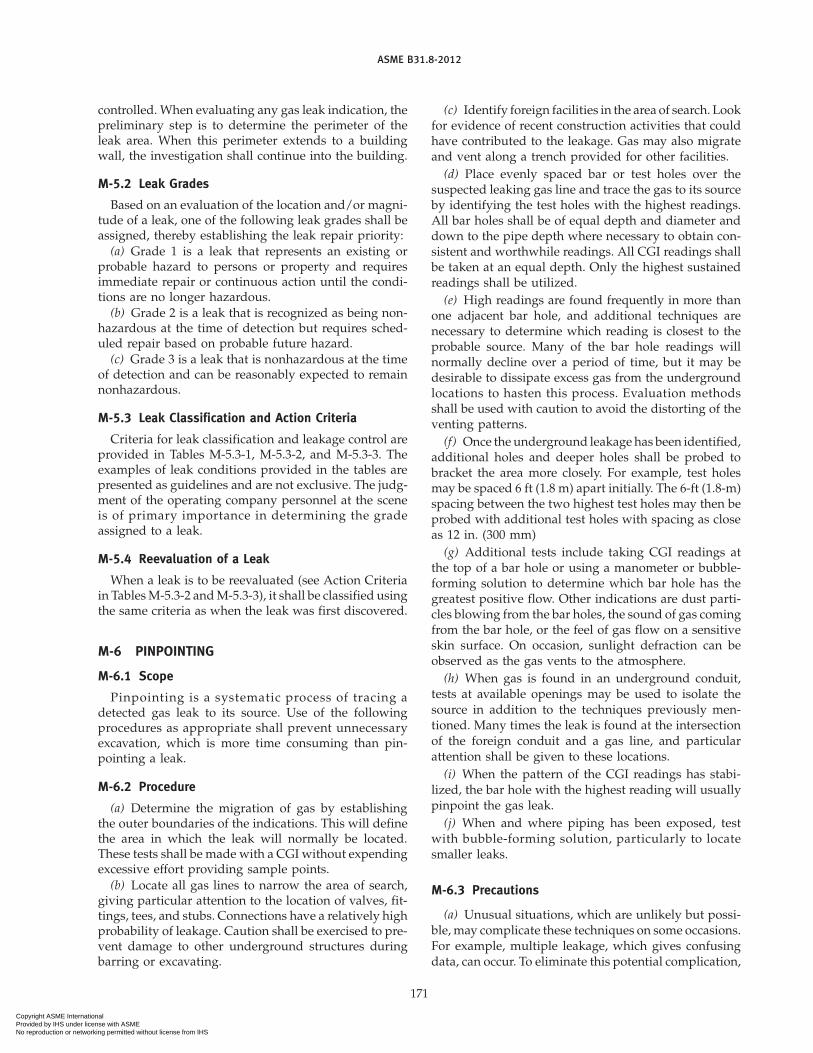
ASME B31.8-2012
controlled. When evaluating any gas leak indication, thepreliminary step is to determine the perimeter of theleak area. When this perimeter extends to a buildingwall, the investigation shall continue into the building.
M-5.2 Leak Grades
Based on an evaluation of the location and/or magni-tude of a leak, one of the following leak grades shall beassigned, thereby establishing the leak repair priority:
(a) Grade 1 is a leak that represents an existing orprobable hazard to persons or property and requiresimmediate repair or continuous action until the condi-tions are no longer hazardous.
(b) Grade 2 is a leak that is recognized as being non-hazardous at the time of detection but requires sched-uled repair based on probable future hazard.
(c) Grade 3 is a leak that is nonhazardous at the timeof detection and can be reasonably expected to remainnonhazardous.
M-5.3 Leak Classification and Action Criteria
Criteria for leak classification and leakage control areprovided in Tables M-5.3-1, M-5.3-2, and M-5.3-3. Theexamples of leak conditions provided in the tables arepresented as guidelines and are not exclusive. The judg-ment of the operating company personnel at the sceneis of primary importance in determining the gradeassigned to a leak.
M-5.4 Reevaluation of a Leak
When a leak is to be reevaluated (see Action Criteriain TablesM-5.3-2 andM-5.3-3), it shall be classified usingthe same criteria as when the leak was first discovered.
M-6 PINPOINTING
M-6.1 Scope
Pinpointing is a systematic process of tracing adetected gas leak to its source. Use of the followingprocedures as appropriate shall prevent unnecessaryexcavation, which is more time consuming than pin-pointing a leak.
M-6.2 Procedure
(a) Determine the migration of gas by establishingthe outer boundaries of the indications. This will definethe area in which the leak will normally be located.These tests shall be made with a CGI without expendingexcessive effort providing sample points.
(b) Locate all gas lines to narrow the area of search,giving particular attention to the location of valves, fit-tings, tees, and stubs. Connections have a relatively highprobability of leakage. Caution shall be exercised to pre-vent damage to other underground structures duringbarring or excavating.
171
(c) Identify foreign facilities in the area of search. Lookfor evidence of recent construction activities that couldhave contributed to the leakage. Gas may also migrateand vent along a trench provided for other facilities.
(d) Place evenly spaced bar or test holes over thesuspected leaking gas line and trace the gas to its sourceby identifying the test holes with the highest readings.All bar holes shall be of equal depth and diameter anddown to the pipe depth where necessary to obtain con-sistent and worthwhile readings. All CGI readings shallbe taken at an equal depth. Only the highest sustainedreadings shall be utilized.
(e) High readings are found frequently in more thanone adjacent bar hole, and additional techniques arenecessary to determine which reading is closest to theprobable source. Many of the bar hole readings willnormally decline over a period of time, but it may bedesirable to dissipate excess gas from the undergroundlocations to hasten this process. Evaluation methodsshall be used with caution to avoid the distorting of theventing patterns.
(f) Once the underground leakage has been identified,additional holes and deeper holes shall be probed tobracket the area more closely. For example, test holesmay be spaced 6 ft (1.8 m) apart initially. The 6-ft (1.8-m)spacing between the two highest test holes may then beprobed with additional test holes with spacing as closeas 12 in. (300 mm)
(g) Additional tests include taking CGI readings atthe top of a bar hole or using a manometer or bubble-forming solution to determine which bar hole has thegreatest positive flow. Other indications are dust parti-cles blowing from the bar holes, the sound of gas comingfrom the bar hole, or the feel of gas flow on a sensitiveskin surface. On occasion, sunlight defraction can beobserved as the gas vents to the atmosphere.
(h) When gas is found in an underground conduit,tests at available openings may be used to isolate thesource in addition to the techniques previously men-tioned. Many times the leak is found at the intersectionof the foreign conduit and a gas line, and particularattention shall be given to these locations.
(i) When the pattern of the CGI readings has stabi-lized, the bar hole with the highest reading will usuallypinpoint the gas leak.
(j) When and where piping has been exposed, testwith bubble-forming solution, particularly to locatesmaller leaks.
M-6.3 Precautions
(a) Unusual situations, which are unlikely but possi-ble, may complicate these techniques on some occasions.For example, multiple leakage, which gives confusingdata, can occur. To eliminate this potential complication,
Copyright ASME International Provided by IHS under license with ASME No reproduction or networking permitted without license from IHS

ASME B31.8-2012
Table M-5.3-1 Leak Classification and Action Criteria: Grade 1
Grade Definition Action Criteria Examples
1 A leak that represents an existing or Requires prompt action [Note (1)] to (1) Any leak that, in the judgment ofprobable hazard to persons or protect life and property, and operating personnel at the scene,property, and requires immediate continuous action until the is regarded as an immediaterepair or continuous action until the conditions are no longer hazard.conditions are no longer hazardous. hazardous. (2) Escaping gas that has ignited.
(3) Any indication of gas that hasmigrated into or under a buildingor into a tunnel.
(4) Any reading at the outside wallof a building, or where gas wouldlikely migrate to an outside wallof a building.
(5) Any reading of 80% LEL, orgreater in a confined space.
(6) Any reading of 80% LEL, orgreater in small substructures(other than gas associated sub-structures) from which gas wouldlikely migrate to the outside wallof a building.
(7) Any leak that can be seen,heard, or felt, and that is in alocation that may endanger thegeneral public or property.
NOTE:(1) The prompt action in some instances may require one or more of the following:
(a) implementing company emergency plan (see para. 850.4)(b) evacuating premises(c) blocking off an area(d) rerouting traffic(e) eliminating sources of ignition(f) venting the area(g) stopping the flow of gas by closing valves or other means(h) notifying police and fire departments
172
Copyright ASME International Provided by IHS under license with ASME No reproduction or networking permitted without license from IHS

ASME B31.8-2012
Table M-5.3-2 Leak Classification and Action Criteria: Grade 2
Grade Definition Action Criteria Examples
2 A leak that is recognized as being Leaks shall be repaired or cleared (1) Leaks Requiring Action Ahead ofnonhazardous at the time of detec- within 1 calendar year, but no Ground Freezing or Other Adversetion, but justifies scheduled repair later than 15 mo from the date Changes in Venting Conditions.based on probable future hazard. the leak was reported. In determin- Any leak that, under frozen or
ing the repair priority, criteria other adverse soil conditions,such as the following shall be con- would likely migrate to the outsidesidered: wall of a building.
(1) amount and migration of gas (2) Leaks Requiring Action Within(2) proximity of gas to buildings 6 mo
and subsurface structures (a) any reading of 40% LEL, or(3) extent of pavement greater, under a sidewalk in a(4) soil type and soil conditions wall-to-wall paved area that
(such as frost cap, moisture, does not qualify as a Grade 1and natural venting). leak
Grade 2 leaks shall be reevaluated (b) any reading of 100% LEL, orat least once every 6 mo until greater, under a street in acleared. The frequency of reevalua- wall-to-wall paved area thattion shall be determined by the has significant gas migrationlocation and magnitude of the and does not qualify as aleakage condition. Grade 1 leak
Grade 2 leaks may vary greatly in (c) any reading less than 80% LELdegree of potential hazard. Some in small substructures (otherGrade 2 leaks, when evaluated by than gas associated substruc-the above criteria, may justify tures) from which gas wouldscheduled repair within the next 5 likely migrate creating a proba-working days. Others will justify ble future hazardrepair within 30 days. During the (d) any reading between 20% LELworking day on which the leak is and 80% LEL in a confineddiscovered, these situations shall spacebe brought to the attention of the (e) any reading on a pipelineindividual responsible for schedul- operating at hoop stress levelsing leak repair. of 30% SMYS, or greater, in a
On the other hand, many Grade 2 Class 3 or 4 location, whichleaks, because of their location does not qualify as a Grade 1and magnitude, can be scheduled leakfor repair on a normal routine (f) any reading of 80% LEL, orbasis with periodic reinspection greater, in gas associated sub-as necessary. structures
(g) any leak that, in the judgmentof operating company person-nel at the scene, is of suffi-cient magnitude to justifyscheduled repair
Table M-5.3-3 Leak Classification and Action Criteria: Grade 3
Grade Definition Action Criteria Examples
3 A leak that is nonhazardous at the These leaks shall be reevaluated dur- Leaks Requiring Reevaluation at Periodic Intervalstime of detection and can be rea- ing the next scheduled survey or (1) any reading of less than 80% LEL in smallsonably expected to remain non- within 15 mo of the date reported, gas associated substructureshazardous. whichever occurs first, until the (2) any reading under a street in areas without
leak is regarded or no longer wall-to-wall paving where it is unlikely theresults in a reading. gas could migrate to the outside wall of a
building(3) any reading of less than 20% LEL in a con-
fined space
173
Copyright ASME International Provided by IHS under license with ASME No reproduction or networking permitted without license from IHS

ASME B31.8-2012
the area shall be rechecked after repairs are completed.Gas may form pockets occasionally and give a strongindication until the cavity in which the pocket hasformed has been vented. Foreign gases, such as gas fromdecomposedmaterial, occasionallymay be encountered.This presence is characterized by fairly constant CGIreadings between 15% and 30% of gas in air throughoutan area. Landfill areas could, thus, give substantiallyhigher readings. Gas detected in sewer systems shall be
174
considered migrating gas leakage until proven other-wise by test and/or analysis.
(b) When pinpointing leakage where the gas is heav-ier than air (LP gas), the gas will normally stay low nearthe pipe level, but may flow downhill. LP gases usuallydo not diffuse rapidly or migrate widely in the soil sothe leak is generally close to the indication. If the gasis venting into a duct or sewer system, it can travelconsiderable distances.
Copyright ASME International Provided by IHS under license with ASME No reproduction or networking permitted without license from IHS

ASME B31.8-2012
NONMANDATORY APPENDIX NRECOMMENDED PRACTICE FOR HYDROSTATIC
TESTING OF PIPELINES IN PLACE
N-1 INTRODUCTION
The purpose of the recommended practice is to citesome of the important steps that should be taken inhydrostatic testing of in-place pipelines. It is intendedto provide basic guidelines only. The portions of thisrecommended practice, which covers the determinationof the pressure at which the pipe specified minimumyield strength is reached, are only usedwhen such deter-mination is needed.
N-2 PLANNING
(a) All pressure tests shall be conducted with dueregard for the safety of people and property. When thetest pressure is above 400 psig (2 760 kPa), appropriateprecautions shall be taken to keep people not engagedin the testing operations out of the testing area whileconducting the hydrostatic test.
(b) Selection of Test Sections and Test Sites. The pipelinemay need to be divided into sections for testing to isolateareas with different test pressure requirements, or toobtain desired maximum and minimum test pressuresdue to hydrostatic head differential. The elevation at thetest site, the high point and low point of the isolatedarea, must be known to maintain the specified pressureat the maximum and the minimum elevations.
(c) Water Source and Water Disposal. Awater source, aswell as location(s) for water disposal, should be selectedwell in advance of the testing. Federal, state, and localregulations should be checked to ensure compliancewith respect to usage and/or disposal of the water. Indisposing of the water after testing, care should be takento prevent damage to crops and excessive erosion orcontamination of streams, rivers, or other waterbodiesincluding groundwater.
(d) Ambient Conditions. Hydrostatic testing in lowtemperature conditions may require
(1) heating of test medium.(2) the addition of freeze point depressants. Cau-
tion should be exercised in the handling of freeze pointdepressants during tests. Disposal of freeze pointdepressants must be carefully planned and executed.
N-3 FILLING
Filling is normally done with a high-volume centrifu-gal pump or pumps. Filling should be continuous and
175
be done behind one or more squeegees or spheres tominimize the amount of air in the line. The progress offilling should bemonitored bymetering the water pumpinto the pipeline and calculating the volume of line filled.
If necessary, a period of temperature stabilizationbetween the ground and fill water should be provided.
N-4 TESTING
(a) Pressure Pump. Normally, a positive displacementreciprocating pump is used for pressurizing the pipelineduring test. The flow capacity of the pump should beadequate to provide a reasonable pressurizing rate. Thepressure rating of the pump must be higher than theanticipated maximum test pressure.
(b) Test Heads, Piping, and Valves. The design pressureof the test heads and piping and the rated pressure ofhoses and valves in the test manifold shall be no lessthan the anticipated test pressure. All equipment shouldbe inspected prior to the test to determine that it is insatisfactory condition.
(c) Pressurization. Following is a sequence forpressurization.
(1) Raise the pressure in the section to nomore than80% of anticipated test pressure and hold for a timeperiod to determine that no major leaks exist.
(2) During this time period, monitor the pressureand check the test section for leakage. Repair any majorleaks that are found.
(3) After the hold time period, pressurize at a uni-form rate to the test pressure. Monitor for deviationfrom a straight line by use of pressure-volume plots(logs or automatic plotter).
(4) When the test pressure is reached and stabilizedfrom pressuring operations, a hold period may com-mence. During this period, test medium may be addedas required to maintain the minimum test pressure.
N-5 DETERMINATION OF PRESSURE REQUIRED TOPRODUCE YIELDING
(a) Pressure-Volume Plot Methods. Ifmonitoring devia-tion from a straight linewith graphical plots, an accurateplot of pressure versus the volume of water pumpedinto the line may be made either by hand or automaticplotter. To make a hand plot, the pump strokes arecounted to determine volume and plotted against pres-sure readings. The plot should be started at a pressure
Copyright ASME International Provided by IHS under license with ASME No reproduction or networking permitted without license from IHS

ASME B31.8-2012
low enough to establish accurately the straight-line por-tion of the pressure-volume plot. The points should beplotted frequently enough so that deviation from thestraight-line portion can be detected readily. The devia-tion from the straight line is the start of the nonlinearportion of the pressure-volume plot and indicates thatthe elastic limit of some of the pipe within the sectionhas been reached.
(b) Yield for unidentified or used pipe [as limited bypara. 841.1.4(a) and allowed under paras. 811.1(f) and817.1.3(h)] is determined by using the pressure at thehighest elevationwithin a test section, atwhich the num-ber of pump strokes (measured volume) per incrementof pressure rise becomes twice the number of pumpstrokes (measured volume) per increment of pressurerise that was required during the straight-line part ofthe pressure-volume plot before any deviation occurs.
(c) For control of maximum test pressure when hoopstress levels exceed 100% SMYS within a test section,one of the following measures may be used:
(1) The pressure at which the number of pumpstrokes (measured volume) per increment of pressurerise becomes twice the number of pump strokes (mea-sured volume) per increment of pressure rise that wasrequired during the straight-line part of the pressure-volume plot before any deviation occurs.
(2) The pressure shall not exceed the pressureoccurring when the number of pump strokes (measuredvolume) taken after deviation from the straight-line partof the pressure-volumeplot, times the volumeper stroke,is equal to 0.002 times the test section fill volume atatmospheric pressure. This represents the averagebehavior of the test section. Individual pipe lengths may
176
experience greater or smaller expansion based on theirrespective mechanical properties.
N-6 LEAK TESTING
If, during the hold period, leakage is indicated, thepressure may be reduced while locating the leak. Afterthe leak is repaired, a new hold period must be startedat full test pressure.
N-7 RECORDS
The operating company shall maintain in its file forthe useful life of each pipeline and main, records show-ing the following:
(a) test medium(b) test pressure(c) test duration(d) test date(e) pressure recording chart and pressure log(f) pressure versus volume plot (if applicable)(g) pressure at high and low elevations(h) elevation at point test pressure measured(i) person(s) conducting test, operator, and testing
contractor, if utilized(j) environmental factors (ambient temperature, rain-
ing, snowing, windy, etc.)(k) manufacturer (pipe, valves, etc.)(l) pipe specifications (SMYS, diameter, wall thick-
ness, etc.)(m) clear identification of what is included in each
test section(n) description of any leaks or failures and their
dispositionThe above records shall be reviewed to ensure that
the requirements of this Code have been met.
Copyright ASME International Provided by IHS under license with ASME No reproduction or networking permitted without license from IHS

ASME B31.8-2012
NONMANDATORY APPENDIX OPREPARATION OF TECHNICAL INQUIRIES
O-1 INTRODUCTION
The ASME B31 Committee, Code for Pressure Piping,will consider written requests for interpretations andrevisions of the Code rules and develop new rules ifdictated by technological development. TheCommittee’s activities in this regard are limited strictlyto interpretations of the rules or to the consideration ofrevisions to the present rules on the basis of new dataor technology. As a matter of published policy, ASMEdoes not approve, certify, rate, or endorse any item,construction, proprietary device, or activity, and, accord-ingly, inquiries requiring such consideration will bereturned. Moreover, ASME does not act as a consultanton specific engineering problems or on the general appli-cation or understanding of the Code rules. If, based onthe inquiry information submitted, it is the opinion ofthe Committee that the inquirer should seek professionalassistance, the inquiry will be returned with the recom-mendation that such assistance be obtained.
Inquiries that do not provide the information neededfor the Committee’s full understanding will be returned.
O-2 REQUIREMENTS
Inquiries shall be limited strictly to interpretations ofthe rules or to the consideration of revisions to the pres-ent rules on the basis of newdata or technology. Inquiriesshall meet the following requirements:
(a) Scope. Involve a single rule or closely related rulesin the scope of the Code.
177
An inquiry letter concerning unrelated subjects willbe returned.
(b) Background. State the purpose of the inquiry,which would be either to obtain an interpretation ofCode rules or to propose consideration of a revisionto the present rules. Provide concisely the informationneeded for the Committee’s understanding of theinquiry, being sure to include reference to the applicableCode Section, edition, addenda (if applicable), para-graphs, figures, and tables. If sketches are provided, theyshall be limited to the scope of the inquiry.
(c) Inquiry Structure(1) Proposed Question(s). The inquiry shall be stated
in a condensed and precise question format, omittingsuperfluous background information, and, whereappropriate, composed in such a way that “yes” or “no”(perhaps with provisos) would be an acceptable reply.The inquiry statement should be technically and editori-ally correct.
(2) Proposed Reply(ies). Provide a proposed replystating what it is believed that the Code requires.
If, in the inquirer’s opinion, a revision to the Code isneeded, recommended wording shall be provided inaddition to information justifying the change.
O-3 SUBMITTALInquiries should be submitted in typewritten form;
however, legible handwritten inquiries will be consid-ered. They shall include the name and mailing addressof the inquirer and be mailed to the following: Secretary,ASME B31 Committee; Three Park Avenue; New York,NY 10016-5990.
Copyright ASME International Provided by IHS under license with ASME No reproduction or networking permitted without license from IHS

ASME B31.8-2012
NONMANDATORY APPENDIX PNOMENCLATURE FOR FIGURES
This Nonmandatory Appendix is in preparation fora future edition of this Code.
178
Copyright ASME International Provided by IHS under license with ASME No reproduction or networking permitted without license from IHS
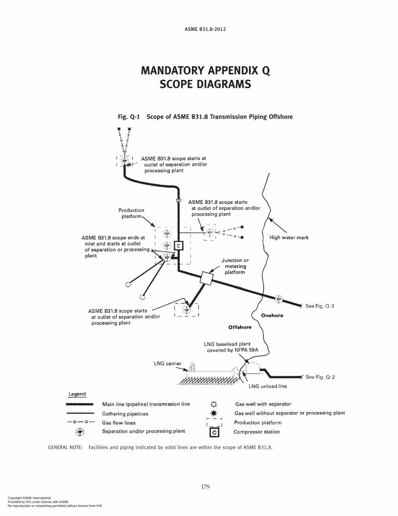
ASME B31.8-2012
MANDATORY APPENDIX QSCOPE DIAGRAMS
Fig. Q-1 Scope of ASME B31.8 Transmission Piping Offshore
GENERAL NOTE: Facilities and piping indicated by solid lines are within the scope of ASME B31.8.
179
Copyright ASME International Provided by IHS under license with ASME No reproduction or networking permitted without license from IHS
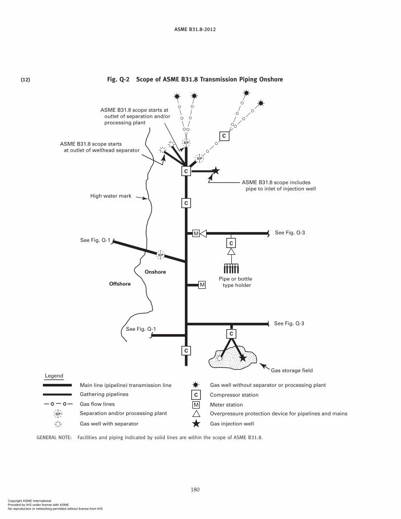
(12)
ASME B31.8-2012
Fig. Q-2 Scope of ASME B31.8 Transmission Piping Onshore
Onshore
Offshore
C
C
C
C
M
M
C
See Fig. Q-3
See Fig. Q-3See Fig. Q-1
See Fig. Q-1
High water mark
ASME B31.8 scope starts at outlet of wellhead separator
ASME B31.8 scope starts at outlet of separation and/or processing plant
S P
S P
S P
Pipe or bottle type holder
ASME B31.8 scope includes pipe to inlet of injection well
Gas storage fieldLegend
Main line (pipeline) transmission line
Gathering pipelines
Gas flow lines
S P Separation and/or processing plant
Gas well with separator
C
M
Gas well without separator or processing plant
Compressor station
Meter station
Overpressure protection device for pipelines and mains
Gas injection well
C
GENERAL NOTE: Facilities and piping indicated by solid lines are within the scope of ASME B31.8.
180
Copyright ASME International Provided by IHS under license with ASME No reproduction or networking permitted without license from IHS

ASME B31.8-2012
Fig. Q-3 Scope of ASME B31.8 Distribution Piping
GENERAL NOTE: Facilities and piping indicated by solid lines are within the scope of ASME B31.8.
181
Copyright ASME International Provided by IHS under license with ASME No reproduction or networking permitted without license from IHS

ASME B31.8-2012
NONMANDATORY APPENDIX RESTIMATING STRAIN IN DENTS
R-1 STRAINStrain in dents may be estimated using data from
deformation in-line inspection (ILI) tools or from directmeasurement of the deformation contour. Direct mea-surement techniques may consist of any method capableof describing the depth and shape terms needed to esti-mate strain. The strain estimating techniques may differdepending on the type of data available. Interpolation orother mathematical techniques may be used to developsurface contour information from ILI or direct measure-ment data. Although a method for estimating strain isdescribed herein, it is not intended to preclude the useof other strain estimating techniques (see also Fig. R-1).
R-2 ESTIMATING STRAINR0 is the initial pipe surface radius, equal to 1⁄2 the
nominal pipe O.D. Determine the indented O.D. surfaceradius of curvature, R1, in a transverse plane throughthe dent. The dent may only partially flatten the pipesuch that the curvature of the pipe surface in the trans-verse plane is in the samedirection as the original surfacecurvature, in which case R1 is a positive quantity. If thedent is re-entrant, meaning the curvature of the pipesurface in the transverse plane is actually reversed, R1is a negative quantity. Determine the radius of curvature,R2, in a longitudinal plane through the dent. The termR2 as used herein will generally always be a negativequantity.Other dimensional terms are thewall thickness,t; the dent depth, d; and the dent length, L.
(a) Calculate the bending strain in the circumferentialdirection as
1 p (1/2)t (1/R0 − 1/R1)
(b) Calculate the bending strain in the longitudinaldirection as
2 p − (1/2)t/R2
182
Fig. R-1 Method for Estimating Strain in Dents
R0
A
A A
R1 0
R1 � 0
R2
R0
A
(c) Calculate the extensional strain in the longitudinaldirection as
3 p (1/2)(d/L)2
(d) Calculate the strain on the inside pipe surface as
i p [12 − 1 (2 + 3) + (2 + 3)2]1/2
and the strain on the outside pipe surface as
o p [12 + 1 (−2 + 3) + (−2 + 3)2]1/2
Copyright ASME International Provided by IHS under license with ASME No reproduction or networking permitted without license from IHS

ASME B31.8-2012
INDEX
Accessibility of vaults, 847.2Adhesive joint, 805.1.3Air piping system, 843.4.3Air receivers, 843.4.3(e)Alloy steel, 804.7.2Ambient temperature, 805.2.2Anchorage for buried piping, 835Arc burns
elimination of, 841.2.4(e)Arctic environment, 865
Backfillingplastic pipe, 842.3.3(d)(2)steel pipe, 841.2.5(c)
Bends, elbows, and miters, 841.2.3Bends in plastic piping, 842.3.4Bottle, 803.8Bottle-tight facilities, control of pressure in, 845.2.1Bottle-type holder, 803.8Branch connection, welded
reinforcement of, Fig. F-6, App. Frules for reinforcement of, examples, App. F
Branches in plastic piping, 842.3.4Buildings intended for human occupancy, 840.2Buried piping, anchorage for, 835
at bends, 835.2forces on pipe joints, 835.4general information, 835.1interconnection of underground lines, 835.6restraint due to soil friction, 835.3supports for buried piping, 835.5
Carbon steel, 804.7.1Casing, insertion in,
of plastic piping, 842.3.3(e)of steel piping, 841.1.11(d)
Cast iron, 804.2Cast iron service lines; see Ductile iron service lines,
849.3connections to mains, 849.6.2use of, 849.3
Check valve, 803.7Class location, change in, 854
description, 840.2.2Clearance between mains and other underground
structuresof plastic piping, 842.2.8
183
of steel piping, 841.1.11(c)Cold climates, materials for use in, 814
corrosion control in, 864.2.8Cold expanded pipe, 804.4Cold-springing, 805.1.4
of piping, 832.3(h)Combustible materials, storage of, in compressor
stations, 853.1.5Compressor stations, 843
construction of building, 843.1.2design of, 843.1electrical facilities, 843.2equipment, 843.3
cooling and lubrication failures, 843.3.6emergency shutdown facilities, 843.3.3(a)engine overspeed stops, 843.3.3(b)explosion prevention, 843.3.7fire protection, 843.3.2fuel gas control, 843.3.5gas treating facilities, 843.3.1liquid removal, 843.3.1(a)liquid removal equipment, 843.3.1(b)mufflers, 843.3.7(a)pressure-limiting requirements, 843.3.4safety devices, 843.3.3ventilations of building, 843.3.7(b)
exits, 843.1.3fenced areas, 843.1.4location of building, 843.1.1piping, 843.4
air piping system, 843.4.3air receivers, 843.4.3(e)fuel gas piping, 843.4.2gas piping, 843.4.1
testing of, 843.4.1(c)hydraulic piping, 843.3.7identification of valves and piping, 843.4.1(d)installation of, 843.4.1(b)lubrication oil piping, 843.4.4specifications for, 843.4.1(a)steam piping, 843.4.6water piping, 843.4.5
Compressors and prime movers, 853.1.1Construction specifications for plastic piping, 842.3.1Container, pipe, 804.3Control piping, 803.5Cooling and lubrication failures, 843.3.6Copper mains, 842.5
Copyright ASME International Provided by IHS under license with ASME No reproduction or networking permitted without license from IHS

ASME B31.8-2012
design of, 842.5.1fittings in, 842.5.1(c)galvanic corrosion, protection against, 842.5.1(e)joints in, 842.5.1(d)valves in, 842.5.1(b)
Copper service lines, 849.5connections to mains, 849.6.4design of, 849.5.1fittings in, 849.5.1(c)galvanic action, protection against, 849.5.1(e)installation of, 849.5.2joints in, 849.5.1(d)valves in, 849.5.1(b)
Corrosioncontrol, 860
Corrosion, pipelineexternal, 861in arctic environments, 865in high-temperature service, 866internal, 864offshore, A860records of, 860.1(e),(f)stress corrosion and other phenomena, 867
Cover and casing, requirements under railroads,roads, streets, or highways
plastic pipe, 842.2.7steel pipelines and mains, 841.1.11
Curb valve, 803.7Customer’s meter, 803.6
Designof copper service lines, 849.5.1of plastic service lines, 849.41of steel service lines, 849.2.1
Design, installation and testing, 840classification of locations, 840.3design factor, F, values of steel
pipe, Tables 841.1.6-1 and 841.1.6-2design formula, steel pipe, 841.1.1fabricated assemblies, steel, 841.1.9(a)general provisions, 840.1least nominal wall thickness, 841.1.5(a)longitudinal joint factor, E, Table 841.1.7-1pipe design values, limitations of, 841.1.3population density indexes, 840.2steel pipe, 841temperature derating factor, T, Table 841.1.8-1
Design factor, Ffor clearance between containers and bottles,
844.3(d)for steel piping, 841.1.1
Design pressure, 805.2Design requirements for vaults, 847.1Diameter, 804.5
nominal outside, 804.5Dimensions
184
SI (metric) conversion, 801.4standard, 801.3
Direct burial of plastic piping, 842.3.3(d)Distribution facilities, abandoning of, 852.4Distribution main, 803.3Distribution piping maintenance, 852
distribution facilities, abandoning of, 852.4leakage surveys, 852.2patrolling, 852.1
Distribution system, 803.3high-pressure, 803.3low-pressure, 803.3
Ductile iron, 804.1Ductile iron pipe
design, 842.1.1installation, 842.1.2
field joints, making, 842.1.2(d)joint restraint, 842.1.2(c)laying, 842.1.2(a)
joints, 842.1.1(e)mechanical, 842.1.1(e)(1)other, 842.1.1(e)(2)threaded, 842.1.1(e)(3)
reuse of, 817.2standard strength, and conformance to
ANSI A21.5.2, 842.1.1(c)standard thickness selection, Table 842.1.1-1thickness, allowable, 842.1.1(d)values of s and f, allowable, 842.1.1(b)wall thickness, determination of, 842.1.1(a)
Ductile iron service lines, 849.3connections to mains, 849.6.2use of, 849.3
Elongation, specified minimum, 804.6Emergency plan, 850.4Emergency shutdown facilities for compressor
stations, 843.3.3(a)Encroachment, parallel, 803.1Engine overspeed stops, 843.3.3(b)Exits in compressor stations, 843.1.3Expansion and flexibility of piping system
components, 832amount of expansion, 832.2flexibility requirements, 832.3
Explosion, prevention of, 843.3.7Exposed piping, supports and anchors for
attachment of supports or anchors, 834.5forces on pipe joints, 834.4materials, design, and installation, 834.3provision for expansion, 834.2
Failure, pipeline, investigation, 850.5Field joints, making, for ductile iron pipe, 842.1.2(d)Fire protection in compressor stations, 843.3.2Fittings
Copyright ASME International Provided by IHS under license with ASME No reproduction or networking permitted without license from IHS

ASME B31.8-2012
in copper mains, 842.5.1(c)in copper service lines, 849.5.1(c)
Fittings other than valves and flangesbranch connections, 831.3.3special components fabricated by welding, 831.35special fittings, 831.3.2standard fittings, 831.3.1
Flanges, light weight, App. IFlattening test for pipe, App. HFlexibility and stress intensification factors, App. EFlow control facilities
design of, 841.1.9(c), 841.1.9(f), 841.1.9(g), 841.1.9(h)Forces on pipe joints, 835.4Fracture control and arrest, 841.1.2
brittle fracture control, 841.1.2(a)ductile fracture arrest, 841.1.2(b)
Fuel gas control, 843.3.5Fuel gas piping, 843.4.2
Galvanic corrosion, protection against, in coppermains, 842.5.1(e)
Gas, 803.1transportation of, 803.1
Gas leakage control criteria, App. MGas main, 803.3Gas piping
identification of valves and piping, 843.4.1(d)installation of, 843.4.1(b)specifications for, 843.4.1(a)testing of, 843.4.1(c)
Gas pressure, control and limiting of, 845high-pressure system uprating for higher maximum
allowable operating pressure, 857in bottle-tight facilities, 845.2.1in high-pressure distribution systems, 845.2.4in low-pressure distribution systems, 845.2.5instrument, control and sample piping, 845.5limiting and relief devices, proof of adequate
capacity and satisfactory performance, 845.4.2low-pressure distribution systems, conversion to
high-pressure systems, 845.2.6of gas delivered to domestic and small customers
from high-pressure distribution systems, 845.2.7operating pressure, maximum allowable for high-
pressure distribution systems, 845.2.4(c)operating pressure, maximum allowable for low-
pressure distribution systems, 845.2.5(c)operating pressure, maximum allowable for steel or
plastic pipelines or mains, 845.2.2overpressuring, accidental, protection against, 845.1pressure relieving and limiting stations, required
capacity, 845.4.1relief and limiting devices, design of, 845.3steel pipeline or main, uprating for higher
maximum allowable operating pressure, 857Gas processing plant, 803.5
185
Gas service line, 803.3Gas storage line, 803.4Gathering line, 803.4Gathering system, 803.4Gouges and grooves
detection of, 841.2.4(a)field repair of, 841.2.4(b)in plastic piping, field repairs of, 842.3.5
Ground temperature, 805.2.2
Handling, hauling, and stringing, 841.2.5(a)Hazards, protection from, for plastic piping, 842.2.6Headers, extruded, App. FHeat fusion joint, 805.1.3(b)High-pressure distribution systems, 803.3
controlling pressure in, 845.2.4maximum allowable operating pressure, 845.2.4(c)uprating to higher maximum allowable operating
pressure, 857Holders
bottle-type, 803.8, 844general provisions, 844.5in exclusive rights-of-way, 844.3(b)special provisions, 844.4
pipe-type, 803.8, 844general provisions, 844.5in exclusive rights-of-way, 844.3(b)in nonexclusive rights-of-way, 844.1
procedures for maintaining in safe operatingcondition, 853.2
Hoop stress, 805.2.3maximum allowable, 805.2.3
Hot taps, 803.1in plastic piping, 842.3.6steel pipelines and mains, 841.2.6
Hydraulic piping, 843.3.7Hydrostatic testing of pipelines in place, App. N
Ignition, accidental, prevention of, 850.6Inquiries, App. OInspection of plastic piping, 842.3.2Installation
backfilling, 841.2.5(c)of copper lines, 849.5.2of customers’ meters and regulators, 848.4of pipe in ditch, 841.2.5(b)
handling, hauling, and stringing, 841.2.5(a)hot taps, 841.2.6miscellaneous operations in, 841.2.5
of steel pipelines and mains, 841.2of pipeline by directional drilling, 841.129of plastic service lines into buildings, 849.4.2(c)of service lines, general provisions, 849.1.1
Copyright ASME International Provided by IHS under license with ASME No reproduction or networking permitted without license from IHS

ASME B31.8-2012
of steel service lines, 849.2.2in bores, steel, 849.2.2(a)into or under buildings, 849.2.2(b)
Instrument, control, and sample piping for controllinggas pressure, 845.5
Instrument piping, 803.5Intent of Code, 802.2Internal corrosion control, 864Interpretations to Code, inquiries concerning, App. O
Joints; see Length, 804.5ductile iron, 842.1.1(e)in copper service lines, 849.5.1(d)plastic pipe, 842.2.9
Leak records, in pipelines, 851.6Leakage investigation terms, App. MLeakage survey, in distribution piping, 852.2Length, 804.5Limiting and relief devices, proof of adequate
capacity and satisfactory performance, 845.4.2Liquid removal in compressor stations, 843.3.1(a)
equipment for, 843.3.1(b)Location
of compressor buildings, 843.1.1of valves
distribution system, 846.2.2transmission, 846.2.1
Location class, 805.1.1, 840.2Long-term hydrostatic strength, 805.1.3Low-pressure distribution systems, 803.3
controlling pressure in, 845.2.5conversion to high-pressure system, 845.2.6maximum allowable operating pressure, 845.2.5(c)
LPG systems, 803.1.9safety requirements for, 856.1
odorization, 856.1ventilation, 834.3.7(c)
Lubricating oil piping, 843.4.4
Mains, gas, 803.3Mains
clearance between mains and other undergroundstructures, plastic piping, 842.2.8
location of service line connections to, 849.1.4Maintenance
compressor station, 853.1combustible materials, storage of, 853.1.5compressors and prime movers, 853.1.1isolation of equipment, 853.1.4relief valves, inspection and testing, 853.1.2
pipeline, 851external corrosion control, 861internal corrosion control, 864markers, 851.6
186
patrolling, 851.2pipeline leak records, 851.6
records of corrosion, 860.1(e),860.1(f)Markers on pipelines, 851.7Marking of materials and equipment, 813Material specifications approved for use under this
Code, App. AMaterials and equipment, 810
qualification of, 811Materials for use in cold climates, 812Maximum allowable hoop stress, 805.2.3Maximum allowable operating pressure, 805.2.1Maximum allowable test pressure, 805.2.1Maximum operating pressure, 805.2.1Meters, 803.6Meter facilities design, 841.1.9(c), 841.1.9(d), 841.1.9(e),
841.1.9(h)Meter set assembly, 803.6Meters and regulators, customers’, 803.6, 848
installation of, 848.4location for, 848.1operating pressure for, 848.2protection from damage, 848.3
Miscellaneous systems, 803.5Monitoring regulator, 803.6Mufflers (silencers), 843.3.7(a)
Nominal outside diameter, 804.5Nominal wall thickness, 804.5
Odorization, 856.1in LPG systems, 856.1
Offshoreabove water and hyperbaric repair procedures for
steel pipelines, A851.4accidental loads, A803allowable longitudinal stress, A842.1.3allowable strains, A842.1.4alternate design for strain, A842.2.3alternative flaw acceptance limits, A826.2.3anchorage for buried piping, A835anchoring, A844.2.5atmospheric corrosion, A861.4atmospheric protection, A861.2backfilling, A844.2.4blasting effects, A850.7bottom soils, A841.25, A844.2.2breakaway coupling, A803buckle, A803
arrestor, A803detector, A803
buckling, A842.1.1cathodic protection requirements, A862.1.2, A862.1coating requirements, A862.1.1collapse, A842.1.2column buckling, A803
Copyright ASME International Provided by IHS under license with ASME No reproduction or networking permitted without license from IHS

ASME B31.8-2012
combined stress, A842.2.2(c)compressor, station design, A843.1
station equipment, A843.3stations, A843
conditions for the reuse and requalification of pipe,A817
connectors, A803corrosion control of offshore pipelines, A860design against
buckling and ovalization, A842.2.4fatigue, A842.2.5fracture, A842.2.6yielding, A842.2.2(b)
design, and protection of special assemblies,A842.2.10
conditions, A841.1considerations, A841environmental loads, A841.3.3factors for offshore pipelines, platform piping,
and pipeline risers, Table A842.2.2-1design, installation, and testing, A840design of
clamps and supports, A842.2.7connectors and flanges, A842.2.8flexible pipe, A842.2.11structural pipeline riser protectors, A842.2.9
design storm conditions, A844.1educational program, A850.4.4electrical
connections and monitoring points, A861.1.4facilities, A843.2interference, A861.1.7isolation, A861.1.3
emergency shutdown facilities, A843.3.3(a)enclosures, A843.1.2environment loads, A841.2.3essential features plans, A850.3, A850.4examination when exposed, A860.2(e)existing installations, A860.2exits, A843.1.3expansion and flexibility, A832extent of examination, A826.2.1external corrosion control, A861external hydrostatic pressure, A803facilities, A843.3.4flexible pipe, A803, A842.1.8gas transmission, A800general, A821, A830.1, A864.1general information, A801general provisions, A840.1, A847.1hoop stress, A842.2.2(a)hyperbaric weld, A803inspection and tests for quality control of welds on
piping systems, A826.2inspection of welds, A826
offshore pipelines, A820
187
processes, A821.2welding procedure, A821.3
installation fatigue, A842.1.5intent, A802.2internal corrosion control, A864liaison, A850.4.3loading classifications, A841.3.1loads imposed by construction equipment and
vessel motions, A841.2.4location class, A854location of compressor facilities, A843.1.1longitudinal stress, A842.2.2(b)material specifications, A814submerged installations, A861.1offshore, A803
below water repair procedures for steel pipelines,A851.4.5
gas transmission, A800gas transmission terms and definitions, A803pipeline system, A803platform, A803repair of flexible pipe, A851.4.6
on-bottom stability, A844operating and maintenance procedures affecting the
safety of gas transmission facilities, A850operational, and design criteria, A842.2.1
design considerations, A841.3loads, A841.3.2
operations, general, A850.1pipe collapse, A803pipeline, maintenance, A851
markers and signs, A851.7patrolling, A851.2
pipelines, A851.4piping system components, A831platform piping, A803pressure limiting requirements for offshore
compression facilities, A843.3.4profile, A841.2.2propagating buckle, A803pull tube, A803
riser, A803qualification, of materials and equipment, A811
of procedures and welders, A823records, A847.5requalification of pipeline systems, A817.4residual stresses, A842.1.7return interval, A803reuse of steel pipe, A817.1riser pipe or pipes installed through a pull tube,
A842.1.7safety devices, A843.3.3scope, A802.1, A821.1, A860.1
and intent, A802shore approaches, A844.3shoreline approaches, A840.2
Copyright ASME International Provided by IHS under license with ASME No reproduction or networking permitted without license from IHS

ASME B31.8-2012
slope failure, A844.4soil liquefaction, A803, A844.5special assemblies, A842.1.6splash zone, A803stability against waves and currents, A844.2standard of acceptability, A826.2.2strength considerations, A842
during installation, A842.1during operations, A842.2
stress relieving, A825submerged facilities, A862.1submerged weight, A844.2.1supports and anchorage for exposed piping, A834system components and fabrication details, A830test, conditions
medium, A847.3pressure, A847.2procedure, A847.4
testing, A847for buckles, A847.7tie-ins, A847.6
transmission facilities, A850trenching, A844.2.3valves, A846venting, A843.3.4(c)weight, A841.2.1
coating, A803Operating and maintenance procedures, 850
features of plan, 850.3requirements, 850.2
Operating, classification of locations, 850.1(b),Table 854.1(c)
Operating company, 803.1Operating pressure
maximum, 805.2.1maximum allowable, 805.2.1maximum allowable for steel or plastic pipelines or
mains, 845.2.2uprating for higher maximum allowable, 857
Operating stress, 805.2.3Overpressure protection, 805.2.1Overpressuring, protection against accidental, 845.1
Parallel encroachment, 803.1Patrolling
distribution mains, 852.1pipelines, 851.2
Pipe, 804.4cold expanded, 804.4container, 804.3manufacturing process, 804.7.3
Pipelines, 803.1arc burns, 841.2.4(d)
elimination of, 841.2.4(e)electrical test leads, steel, 861.1.4failure investigation, 850.5
188
installation, miscellaneous operations in, 841.2.5backfilling, 841.2.5(c)handling, hauling, and stringing, 841.2.5(a)hot taps, 841.2.6installation in ditch, 841.2.5(b)
leak tests for operating at less than 100 psi, 841.3.5leak tests for operating at 100 psi or more, 841.3.4on private rights-of-way of electric transmission
lines, 845.3(c), 850.6(c)precautions for avoiding explosions during
construction, 841.2.7protective coatings for underground piping,
inspection of existing steel, 860.2(e)new steel, 861.1.1
purging, 841.2.7(e)repair of, at hoop stress levels at or above 30%
SMYS, 851.4surveillance of, 851.1test requirements, 841.3
at hoop stress levels of less than 30% of yield,841.3.3, Table 841.3.3-1
at hoop stress levels of 30% or more of yield,841.3.2, Table 841.3.2-1
testing after construction, 841.3tests, safety during, 841.3.6
Pipelines and mainsclearance between other underground structures,
841.1.11(c)cover requirements
mains, 841.1.11(a)pipelines, 841.1.11(b)
dents, 841.2.4(c)gouges and grooves
detection of, 841.2.4(a)field repair of, 841.2.4(b)
pipe surface requirements for a hoop stress of 20%or more of yield, 841.2.4
protection from hazards, 841.1.10requirements for casings under railroads, highways,
roads, or streets, 841.1.11(d)steel
bends, miters, and elbows, 841.2.3construction specifications, 841.2.1corrosion
external criteria, 861internal criteria, 864
inspection provisions, 841.2.2installation of, 841.2material specifications, 814.1.2reuse of steel pipe, 856.1
Pipe-type holder, 803.8Piping, compressor station, 843.4
gas, 843.4.1Piping systems, 803.2Piping system components, 831
branch connections, welded, reinforcement of, 831.4
Copyright ASME International Provided by IHS under license with ASME No reproduction or networking permitted without license from IHS
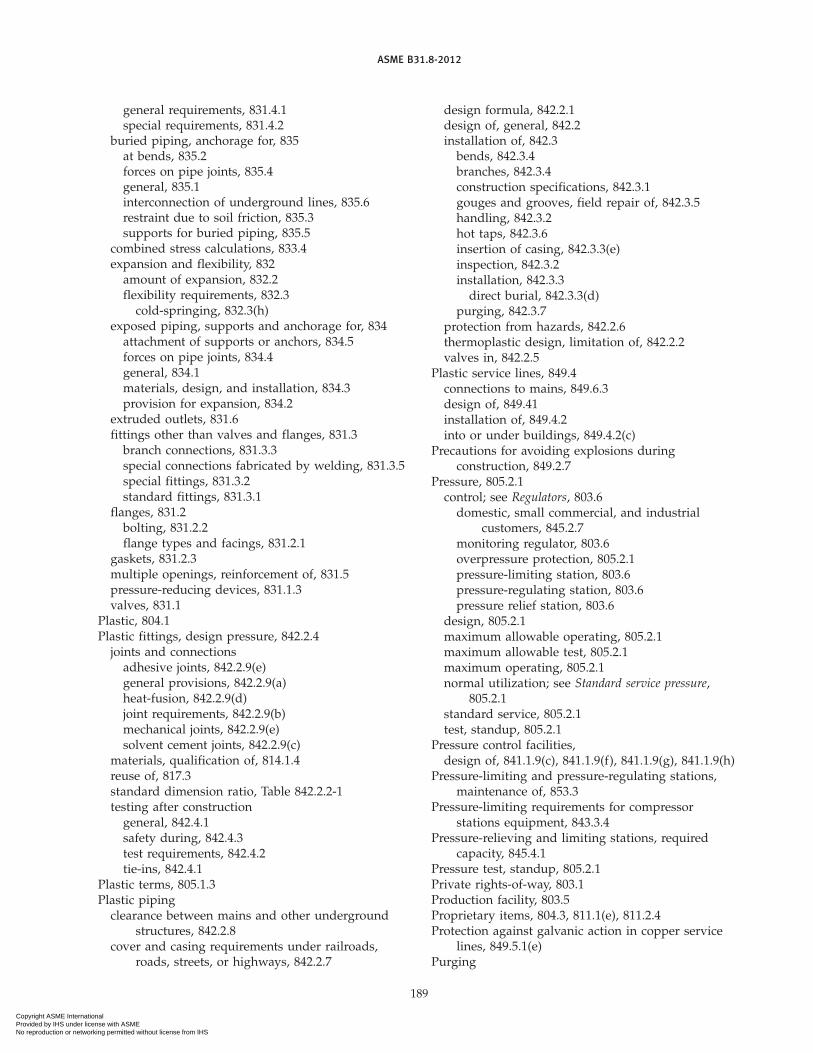
ASME B31.8-2012
general requirements, 831.4.1special requirements, 831.4.2
buried piping, anchorage for, 835at bends, 835.2forces on pipe joints, 835.4general, 835.1interconnection of underground lines, 835.6restraint due to soil friction, 835.3supports for buried piping, 835.5
combined stress calculations, 833.4expansion and flexibility, 832
amount of expansion, 832.2flexibility requirements, 832.3
cold-springing, 832.3(h)exposed piping, supports and anchorage for, 834
attachment of supports or anchors, 834.5forces on pipe joints, 834.4general, 834.1materials, design, and installation, 834.3provision for expansion, 834.2
extruded outlets, 831.6fittings other than valves and flanges, 831.3
branch connections, 831.3.3special connections fabricated by welding, 831.3.5special fittings, 831.3.2standard fittings, 831.3.1
flanges, 831.2bolting, 831.2.2flange types and facings, 831.2.1
gaskets, 831.2.3multiple openings, reinforcement of, 831.5pressure-reducing devices, 831.1.3valves, 831.1
Plastic, 804.1Plastic fittings, design pressure, 842.2.4
joints and connectionsadhesive joints, 842.2.9(e)general provisions, 842.2.9(a)heat-fusion, 842.2.9(d)joint requirements, 842.2.9(b)mechanical joints, 842.2.9(e)solvent cement joints, 842.2.9(c)
materials, qualification of, 814.1.4reuse of, 817.3standard dimension ratio, Table 842.2.2-1testing after construction
general, 842.4.1safety during, 842.4.3test requirements, 842.4.2tie-ins, 842.4.1
Plastic terms, 805.1.3Plastic piping
clearance between mains and other undergroundstructures, 842.2.8
cover and casing requirements under railroads,roads, streets, or highways, 842.2.7
189
design formula, 842.2.1design of, general, 842.2installation of, 842.3
bends, 842.3.4branches, 842.3.4construction specifications, 842.3.1gouges and grooves, field repair of, 842.3.5handling, 842.3.2hot taps, 842.3.6insertion of casing, 842.3.3(e)inspection, 842.3.2installation, 842.3.3
direct burial, 842.3.3(d)purging, 842.3.7
protection from hazards, 842.2.6thermoplastic design, limitation of, 842.2.2valves in, 842.2.5
Plastic service lines, 849.4connections to mains, 849.6.3design of, 849.41installation of, 849.4.2into or under buildings, 849.4.2(c)
Precautions for avoiding explosions duringconstruction, 849.2.7
Pressure, 805.2.1control; see Regulators, 803.6
domestic, small commercial, and industrialcustomers, 845.2.7
monitoring regulator, 803.6overpressure protection, 805.2.1pressure-limiting station, 803.6pressure-regulating station, 803.6pressure relief station, 803.6
design, 805.2.1maximum allowable operating, 805.2.1maximum allowable test, 805.2.1maximum operating, 805.2.1normal utilization; see Standard service pressure,
805.2.1standard service, 805.2.1test, standup, 805.2.1
Pressure control facilities,design of, 841.1.9(c), 841.1.9(f), 841.1.9(g), 841.1.9(h)
Pressure-limiting and pressure-regulating stations,maintenance of, 853.3
Pressure-limiting requirements for compressorstations equipment, 843.3.4
Pressure-relieving and limiting stations, requiredcapacity, 845.4.1
Pressure test, standup, 805.2.1Private rights-of-way, 803.1Production facility, 803.5Proprietary items, 804.3, 811.1(e), 811.2.4Protection against galvanic action in copper service
lines, 849.5.1(e)Purging
Copyright ASME International Provided by IHS under license with ASME No reproduction or networking permitted without license from IHS

ASME B31.8-2012
of pipelines and mains, 841.2.7(e)plastic piping, 842.3.7
Regulator, 803.6monitoring, 803.6service, 803.6
Relief and limiting devices, design of, 845.3Relief station; see Pressure relief station, 803.6Relief valves, inspection and testing of, in compressor
stations, 853.1.2Repair procedures
design, 841.2.4operations, 851.4
Restraint due to soil friction, 835.3Revisions to Code, inquiries concerning, App. ORights-of-way, exclusive
bottle-type holders in, 844.3pipe-type holders in, 844.3
Rights-of-way, private, 803.1
Safetydevices for compressor stations, 843.3.3during tests of pipelines and mains, 841.3.6during tests of plastic pipe, 842.4.3
Sample piping, 803.5Scope of Code, 802.1Secondary stress, 805.2.3Sealing of vaults, 847.3Service lines, 849
gas, 803.3installation of, 849.1.1location of service line connections to main piping,
849.1.4location of valves, 849.1.3plastic
connections to mains, 849.6.5design of, 849.4.1installation of, 849.4.2into or under buildings, 849.4.2(c)
steel, 841.2connections to mains, 849.6.1design of, 849.2.1installation of, 849.2.2
in bores, 849.2.2(a)into buildings, 849.2.2(b)
testing of, after construction, 849.1.5requirements, 849.1.5(b)
valves suitable for, 849.1.2valve, 803.7
Service pressure, standard, 805.2.1Service regulator, 803.6Solvent cement joint, 805.1.3Sour gas terms, B803 (Ch. IX)Spacing required for valves, 846.1Specification for equipment, 815Specification of materials, 814
190
Specified minimum elongation, 804.6Specified minimum tensile strength, 804.6Specified minimum yield strength, 804.6Standard dimension ratio, 805.1.3Standard service pressure, 805.2.1Standards and specifications, 801.1
approved for use under this Code, App. AStandup pressure test, 805.2.1Station
pressure-limiting, 803.6pressure-regulating, 803.6pressure-relief, 803.6
Steam piping, 843.4.6Steel
alloy, 804.7.2carbon, 804.7.1
Steel pipereuse of used, 817.1
bending properties, 817.1.3(b)determination of wall thickness, 817.1.3(c)hydrostatic test, 817.1.3(i)inspection of, 817.1.3(a)joint, longitudinal, 817.1.3(d)S value, 817.1.3(h)surface defects, 817.1.3(f)weldability, 817.1.3(e)yield strength, determination of, 817.1.3(g)
Stop valve, 803.7Storage field, 803.2Strength
long-term hydrostatic, 805.1.3specified minimum tensile, 804.6specified minimum yield, 804.6tensile, 804.6yield, 804.6
Stress, 805.6combined, 833.4hoop, 805.2.3maximum allowable, 805.2.3operating, 805.2.3secondary, 805.2.3unit; see Stress, 805.2.3wall thickness, nominal, 804.5
Stress corrosion and other phenomena, 867Supports and anchors for exposed piping
attachment of, 834.5forces on pipe joints, 834.4materials, design, and installation, 834.3provision for expansion, 834.2
Supports for buried piping, 835.5Surveys, leakage investigation, App. M
Temperature, 805.2.2ambient, 805.2.2ground, 805.2.2
Tensile strength, 804.2.3
Copyright ASME International Provided by IHS under license with ASME No reproduction or networking permitted without license from IHS

ASME B31.8-2012
specified minimum, 804.6Test pressure, maximum allowable, 805.2.1Test requirements for pipelines, 841.3
at hoop stress levels of less than 30% of yield,841.3.3, Table 841.3.3-1
at hoop stress levels of 30% or more of yield,841.3.2, Table 841.3.2-1
Testing repairs, 851.4Tests of welders, App. GThermoplastic, 804.1Thermoplastic design, limitations of, 842.2.2Thermoplastic pipe, wall thickness and standard
dimension ratio, Table 842.2.2-1Thermosetting plastic, 804.1Thermosetting plastic design, limitations of, 842.2.3Thermosetting plastic pipe, diameter and wall
thickness, Table 842.2.3-1Transmission facilities, abandoning of, 851.8Transmission line, 803.2Transmission system, 803.2Transportation of gas, 803.1Transportation of line pipe, 816
Unit stress; see Stress, 805.2.3Uprating, 805.2.4, 857Utilization pressure, normal; see Standard service
pressure, 805.2.1
Valves, 803.7cast iron, 831.1.1(c)check, 803.7curb, 803.7ductile iron, 831.1.1(b)in compressor stations, 831.1.1(a), 843.4.1(a)in copper mains, 842.5.1(b)in copper service lines, 849.5.1(b)location of
distribution system, 846.2.2service line, 849.1.3transmission, 846.2.1
maintenance of, 853.4distribution system, 853.4.2pipeline, 853.4.1service line, 853.4.3
service line, 803.7spacing, required, 846.1spacing, revised, 854.4stop, 803.7suitable for service line, 849.1.2
191
Vaults, 803.1, 847accessibility, 847.2drainage and waterproofing of, 847.4maintenance of, 853.5sealing, venting, and ventilation, 847.3structural design requirements, 847.1
Ventilationof building in compressor stations, 843.3.7(b)in LPG systems, 843.3.7of vaults, 847.3
Wall thicknessductile iron, determination of, 842.1.1(a)nominal, 804.5
Water piping, 843.4.5Welders, qualifications for, 823Welding, 820
butt welds, preparation for, 822.1fillet welds, preparation for, 822.2general information, 821inspection and tests
piping systems with hoop stress levels less than20% of yield strength, 826.2
piping systems with hoop stress levels of 20% ormore of yield strength, 826.3
on bottle-type holders, 844.4(c)preheating, 824preparation for, 822qualification of procedures and welders, 823
piping systems with hoop stress less than 20% ofyield strength, 823.1
piping systems with hoop stress levels of 20% ormore of yield strength, 823.2
records, qualification, 823.4requalification requirements for welders, 823.3variables requiring separate qualification, 823.2.3welders, 823
seal welds, preparation, 822.3special components fabricated by, 831.3.5standards of acceptability, 821.4stress-relieving, 825
equipment, 825.8methods, 825.7temperature, 825.6
terms, 821.7
Yield strength, 804.6specified minimum, 804.6specified minimum for steel and iron pipe, App. D
Copyright ASME International Provided by IHS under license with ASME No reproduction or networking permitted without license from IHS

INTENTIONALLY LEFT BLANK
192
Copyright ASME International Provided by IHS under license with ASME No reproduction or networking permitted without license from IHS

ASME B31.8 INTERPRETATIONS VOLUME 16
ASME B31.8 INTERPRETATIONSVOLUME 16
Replies to Technical InquiriesMarch 2010 Through March 2012
Interpretations 16-1 Through 16-17
It has been agreed to publish interpretations issued by the B31 Committee concerningASME B31.8 as part of the update service to the Code. The interpretations have been asssignednumbers in chronological order. Each interpretation applies either to the latest Edition or Addendaat the time of issuance of the interpretation or the Edition or Addenda stated in the reply.Subsequent revisions to the Code may have superseded the reply.
These replies are taken verbatim from the original letters, except for a few typographical andeditorial corrections made for improved clarity.
ASME procedures provide for reconsideration of these interpretations when or if additionalinformation that the inquirer believes might affect the interpretation is available. Further, personsaggrieved by an interpretation may appeal to the cognizant ASME committee or subcommittee.As stated in the Statement of Policy in the Code documents, ASME does not “approve,” “certify,”“rate,” or “endorse” any item, construction, proprietary device, or activity.
I-1
Copyright ASME International Provided by IHS under license with ASME No reproduction or networking permitted without license from IHS

ASME B31.8 INTERPRETATIONS VOLUME 16
B31.8Subject Interpretation File No.
Appendix F . . . . . . . . . . . . . . . . . . . . . . . . . . . . . . . . . . . . . . . . . . . . . . . . . . . . . . . . . . . . . 16-11 11-376Para. 802.12(f), Injection and Production Flow Lines . . . . . . . . . . . . . . . . . . . . . . . . . 16-13 07-1469,
07-1470Para. 831.2.2, ASTM A307 Grade B Bolting for B16.5 Flanges in Classes 150
and 300 Service . . . . . . . . . . . . . . . . . . . . . . . . . . . . . . . . . . . . . . . . . . . . . . . . . . . . . . . . 16-4 10-718Para 831.2.2, Follow-Up Inquiry on ASTM A307 Grade B Bolting for
B16.5 Flanges in Classes 150 and 300 Service . . . . . . . . . . . . . . . . . . . . . . . . . . . . . . 16-10 11-371Para. 831.4.1(c) and Appendix F . . . . . . . . . . . . . . . . . . . . . . . . . . . . . . . . . . . . . . . . . . . 16-8 09-1699Para. 841.31, General Provisions . . . . . . . . . . . . . . . . . . . . . . . . . . . . . . . . . . . . . . . . . . . 16-3 07-1472Para. 842.2, Design of Plastic Piping, General Provisions . . . . . . . . . . . . . . . . . . . . . 16-9 10-1001Para. 845.2.2, MAOP and Para. 845.4.1, Capacity of Pressure-Relieving
and Pressure-Limiting Stations and Devices. . . . . . . . . . . . . . . . . . . . . . . . . . . . . . . 16-14 10-1195Para. 845.4.1, Transient Overpressure . . . . . . . . . . . . . . . . . . . . . . . . . . . . . . . . . . . . . . . 16-16 11-1574Para. 845.411, Hoop Stress Calculations. . . . . . . . . . . . . . . . . . . . . . . . . . . . . . . . . . . . . 16-2 10-162Para. A842.2.2, Design Against Yielding . . . . . . . . . . . . . . . . . . . . . . . . . . . . . . . . . . . . 16-12 11-377Para. A842.2.2, Design Against Yielding and Para. A842.2.3, Alternate Design
for Strain. . . . . . . . . . . . . . . . . . . . . . . . . . . . . . . . . . . . . . . . . . . . . . . . . . . . . . . . . . . . . . 16-15 11-1573Paras. A842.2.2(a), A842.2.2(b), and A842.2.2(c) . . . . . . . . . . . . . . . . . . . . . . . . . . . . . . 16-1 10-23Para. A842.2.2(a), Hoop Stress . . . . . . . . . . . . . . . . . . . . . . . . . . . . . . . . . . . . . . . . . . . . . 16-6 10-1056Para. A842.2.2(a), Hoop Stress and Para. A847.2, Test Pressure . . . . . . . . . . . . . . . . 16-5 10-1057Para. A842.2.2(a), Hoop Stress and Para. A847.2, Test Pressure . . . . . . . . . . . . . . . . 16-7 10-1644Para. A847.2, Test Pressure . . . . . . . . . . . . . . . . . . . . . . . . . . . . . . . . . . . . . . . . . . . . . . . . 16-17 12-121
I-2
Copyright ASME International Provided by IHS under license with ASME No reproduction or networking permitted without license from IHS

ASME B31.8 INTERPRETATIONS VOLUME 16
Interpretation: 16-1
Subject: ASME B31.8-2007, Paras. A842.2.2(a), A842.2.2(b), and A842.2.2(c)
Date Issued: March 10, 2010
File: 10-23
Question (1): The equation for hoop stress in para. A842.2.2(a) has a temperature deratingfactor in the formula, whereas the equations for longitudinal stress and combined stress inparas. A842.2.2(b) and A842.2.2(c) do not use a temperature derating factor. Is this correct?
Reply (1): Yes.
Question (2): Does ASME B31.8 use temperature derated values of Specified Minimum YieldStrength?
Reply (2): No.
Interpretation: 16-2
Subject: ASME B31.8-2007, Para. 845.411, Hoop Stress Calculations
Date Issued: March 10, 2010
File: 10-162
Question (1): Is it allowed to use the Lame formula to determine hoop stress when determiningincidental pressure for an onshore pipeline in accordance with para. 845.411?
Reply (1): No.
Question (2): Is it required to multiply the hoop stress by the Location Class Basic DesignFactor, F, for the capacity check per para. 845.411?
Reply (2): No.
Interpretation: 16-3
Subject: ASME B31.8-2003, Para. 841.31, General Provision
Date Issued: June 30, 2010
File: 07-1472
Question (1): With respect to para. 841.31, is a flange-end valve considered to be a nonweldedtie-in connection?
Reply (1): Yes, provided the valve serves as a tie-in point after construction and testing of thepipeline or piping.
Question (2): Is it mandatory for a pretested flange-end valve to be part of the piping systemduring hydrotesting?
Reply (2): No. Per para. 841.31, nonwelded tie-in connections not pressure tested after construc-tion shall be leak tested.
I-3
Copyright ASME International Provided by IHS under license with ASME No reproduction or networking permitted without license from IHS

ASME B31.8 INTERPRETATIONS VOLUME 16
Interpretation: 16-4
Subject: ASME B31.8-2010; Para. 831.2.2, ASTM A307 Grade B Bolting for B16.5 Flanges inClasses 150 and 300 Service
Date Issued: July 7, 2010
File: 10-718
Question: Does ASME B31.8 allow the use of ASTM A307 Grade A bolts in addition to Grade Bbolts in para. 831.2.2(b)?
Reply: No.
Interpretation: 16-5
Subject: ASME B31.8-2010, Para. A842.2.2(a), Hoop Stress and Para. A847.2, Test Pressure
Date Issued: July 30, 2010
File: 10-1057
Question (1): In para. A842.2.2(a), eq. (2) is for thin-walled pipe, and eq. (3) is for thick-walledpipe. However, if we go by what is given in these two Code equations, the pipe thickness forthick-walled pipes will be less than the pipe thickness for thin-walled pipes. Therefore, is therea typographical or drafting error in eqs. (3) and (5) in this section?
Reply (1): The equations are all correct, but it is not clearly identified that eqs. (2) and (4) arefor U.S. Customary Units and that eqs. (3) and (5) are for SI Units. Furthermore, there is apublishing error in the Note following these equations. The Note should read: “It is recommendedthat eq. (2) or (3) be used for D/t greater than or equal to 30 and that eq. (4) or (5) be used forD/t less than 30.” Errata has been issued to correct these publishing errors.
Question (2): We have a pipeline where the corrosion allowance is 6 mm and 12.5% fabricationallowance. Is the hoop stress calculation under ASME B31.8, Chapter VIII (para. A842.2.2) to bebased only on nominal wall thickness?
Reply (2): Yes.
Question (3): If no, then what are the maximum limits for corrosion and fabrication allowancesbeyond which we need to factor them while calculating the Hoop Stress?
Reply (3): The hoop stress calculations under ASME B31.8, Chapter VIII are to be based onlyon nominal wall thickness.
Question (4): When reading paras. A842.2.2(a) and A847.2, our interpretation for F1, hoop stressdesign factor for offshore pipelines, for a pressure test is that it should be equal to 1. Therefore,is it correct to take the F1 design factor for offshore pipelines for a pressure test to be equal to 1?
Reply (4): No. As stated in Table A842.2.2-1, the hoop stress design factor, F1, for offshorepipelines shall be 0.72. There is no hoop stress design factor, F1, for pressure tests.
Question (5): If no, then what is the correct design factor for the above case?
Reply (5): See reply to Question (4).
I-4
Copyright ASME International Provided by IHS under license with ASME No reproduction or networking permitted without license from IHS

ASME B31.8 INTERPRETATIONS VOLUME 16
Interpretation: 16-6
Subject: ASME B31.8-2010, Para. A842.2.2(a), Hoop Stress
Date Issued: October 20, 2010
File: 10-1056
Question: Can the hoop stress formula in para. A842.2.2(a), eq. (4), be revised as noted below?For an isotropic elastic pipe, this technical inquiry proposes the following formulation for hoopstress calculation.
Sh p (Pi − Pe)� − Pi (1)
where
� p �2�� tD� − � t
D�2
�−1
p 2�Ao
As� (2)
Ao p external cross sectional area of pipeAs p pipe material cross sectional area (cross sectional area of pipe steel)
The proposed formulation, eq. (1), is based on Lame’s solution for hoop stress at the insidediameter of a cylinder subject to a differential pressure, i.e., internal and external pressure.Equation (1) predicts the hoop stress exactly when results are compared to finite element solutionusing eight-node solid continuum element.
The proposed formulation of eq. (1) is a replicate of the second equation of para. A842.2.2(a)but in a more concise and a practical format. The proposed hoop stress formulation of eq. (1) isin terms of Ao and As (i.e., pipe outer and material cross-sectional areas), which gives a directimplication of material usage in resisting the tensile hoop stress. The proposed hoop stressformulation is also shown in terms of wall thickness-to-diameter ratio (t/D), to assist designersin performing normalized parametric studies.
The proposed formulation of eq. (2) is more appropriate for deepwater application, wherehydrostatic collapse pressure often results in pipe diameter-to-wall thickness ratios of less than20, where the existing equation in ASME B31.8 may grossly overestimate the hoop stress.
Reply: Thank you for your considered discussion on the hoop stress equation formulation.However, use of the proposed Lame equation to compute the hoop stress at the pipeline internaldiameter for offshore pipelines does not have any significant advantage over the current equation,and is more difficult to use for development of pipeline wall thickness design. We do not agreewith your assertion that the formula in para. A842.2.2(a), eq. (4) will grossly overestimate thehoop stress. We consider that the existing eq. (4) in para. A842.2.2(a) is appropriate for the D/tranges covered in ASME B31.8.
I-5
Copyright ASME International Provided by IHS under license with ASME No reproduction or networking permitted without license from IHS

ASME B31.8 INTERPRETATIONS VOLUME 16
Interpretation: 16-7
Subject: ASME B31.8-2010, Para. A842.2.2(a), Hoop Stress and Para. A847.2, Test Pressure
Date Issued: November 9, 2010
File: 10-1644
Question: Previously, I had sent an Inquiry to ASME asking if it was correct to take the F1design factor for offshore pipelines for a pressure test to be equal to 1 when considering thewording stated in paras. A842.2.2(a) and A847.2. The reply to this Inquiry (Interpretation 16-5,File 10-1057) stated that there is no hoop stress design factor, F1, for pressure tests. However, Ihave an additional question related to this response. Is the following the correct formula forcomputing the hoop stress for a pressure test?
S ≤ ST
Reply: No. There is no maximum hoop stress limit identified in the Code for a hydrotest. TheCautionary Note in para. A847.2 was written to caution the Code user that conditions may existthat could yield the pipe.
Interpretation: 16-8
Subject: ASME B31.8-2010, Para. 831.4.1(c) and Appendix F
Date Issued: March 22, 2011
File: 09-1699
Question: In a fabricated branch connection, where the opening made in the header wall issmaller than the inside diameter of the branch pipe, may the full thickness of the header wallbetween the undersized branch hole and the inside of the branch pipe be considered to bereinforcement for purposes of area replacement calculation?
Reply: Yes.
I-6
Copyright ASME International Provided by IHS under license with ASME No reproduction or networking permitted without license from IHS

ASME B31.8 INTERPRETATIONS VOLUME 16
Interpretation: 16-9
Subject: ASME B31.8-2010, Para. 842.2 Design of Plastic Piping, General Provisions
Date Issued: March 22, 2011
File: 10-1001
Question (1): Reinforced thermoplastic pipe (RTP) as described in, for example, ISO TS 18226,Plastics pipes and fittings — Reinforced thermoplastics pipe systems for the supply of gaseousfuels for pressures up to 4 MPa (40 bar), or API RP 15S, Qualification of Spoolable ReinforcedPlastic Line Pipe, is not specifically identified as acceptable in para. 842.2. Is RTP allowed to beused for gas pipeline service?
Reply (1): No. However, certain products may be qualified for use by methods described insection 811.
Question (2): Is reinforced thermoplastic pipe (RTP) subject to the same pressure design limita-tions as thermoplastic pipe per para. 842.2.2?
Reply (2): No. See response to Question (1). The ASME B31.8 Code Committee is consideringmodifications to the current code specifically to include certain types of reinforced thermoplasticpipe that may be described in API RP 15S, ISO TS 18226, and other reinforced thermoplastic pipestandards.
Interpretation: 16-10
Subject: ASME B31.8-2010, Para 831.2.2, Follow-Up Inquiry on ASTM A307 Grade B Bolting forB16.5 Flanges in Classes 150 and 300 Service
Date Issued: March 22, 2011
File: 11-371
Question (1): Is there a conflict between ASME B31.8, para. 831.2.2 referencing ASME B16.5and ASTM A307, Grade B bolting?
Reply (1): No. ASME B16.5 references ASTM A307 Grade B bolts in Table 1B under the categoryof Low Strength Bolting. In ASME B16.5, the Grade B bolts are limited to use with Classes 150and 300 flanged joints, used with nonmetallic gasket materials at temperatures between −29°Cto 200°C (−20°F to 400°F). These same conditions are required in ASME B31.8, para. 831.2.2. [Thetemperature range in the ASME B31.8-2010 actually reads −29°C to 232°C (−20°F to 450°F). Thereis an errata scheduled for publication to correct the high temperature discrepancy.] TheASTMA307statement that the Grade B bolts are intended for use with cast iron flanges does not precludetheir use in steel flanges under the conditions stated above.
Question (2): Since ASME B31.8 is referencing ASME B16.5, which is for steel flanges, shouldn’tit also reference ASTM A307, Grade A bolts since these are used for general purpose (steel)?
Reply (2): No. ASTM A307, Grade A bolts are not referenced in ASME B16.5. The Grade Abolts allow sulfur levels up to 0.15% for ease of machining, and therefore may possess low fracturetoughness properties unsuitable for natural gas service.
I-7
Copyright ASME International Provided by IHS under license with ASME No reproduction or networking permitted without license from IHS

ASME B31.8 INTERPRETATIONS VOLUME 16
Interpretation: 16-11
Subject: ASME B31.8-2010, Appendix F
Date Issued: March 22, 2011
File: 11-376
Question (1): In the examples in Appendix F illustrating the application of the rules for reinforce-ment of welded branch connections for an onshore pipeline system, is the Design Factor, F, takenfrom Table 841.1.6-1?
Reply (1): No. A welded branch connection on an onshore pipeline system is a FabricatedAssembly, as defined in para. 841.1.9(a). Therefore, the Design Factor, F, is taken fromTable 841.1.6-2.
Question (2): In the examples in Appendix F illustrating the application of the rules for reinforce-ment of welded branch connections, would the Design Factor, F, be taken from the Hoop Stresscolumn in Table A842.2.2-1 for an offshore pipeline system?
Reply (2): Yes.
Interpretation: 16-12
Subject: ASME B31.8-2010, Para. A842.2.2, Design Against Yielding
Date Issued: March 22, 2011
File: 11-377
Question (1): My understanding of the test pressure criterion is the following:
Sh p (Pi − Pe)D2t
< SMYS
Is this correct?
Reply (1): No. The formula that you have noted is used to compute hoop stress. It is not a testpressure criterion. Furthermore, Sh as defined in eqs. (1) and (2) in para. A842.2.2 includes aDesign Factor, F, and a Temperature Derating Factor, T.
Question (2): Since the nominal wall thickness is used in eq. (2) in para. A842.2.2 to computehoop stress, does this mean that during a hydrotest, ASME B31.8 allows hoop stress to be 12.5%higher than SMYS when assuming a pipe manufacturing mill tolerance of −12.5%?
Reply (2): No. When the Design Factor is included in the hoop stress formula, the hoop stressduring a hydrotest will not be 12.5% higher than SMYS.
I-8
Copyright ASME International Provided by IHS under license with ASME No reproduction or networking permitted without license from IHS

ASME B31.8 INTERPRETATIONS VOLUME 16
Interpretation: 16-13
Subject: ASME B31.8-2007, Para. 802.12(f), Injection and Production Flow Lines
Date Issued: March 23, 2011
File: 07-1469 and 07-1470
Question (1): In accordance with ASME B31.8-2007, does the Code exclude flow lines betweengas injection wells and gas injection facilities?
Reply (1): Yes.
Question (2): In accordance with ASME B31.8-2007, does the Code exclude flow lines betweengas production wells and gas separation facilities?
Reply (2): Yes.
Interpretation: 16-14
Subject: ASME B31.8-2007, Para. 845.2.2, MAOP and Para. 845.4.1, Capacity of Pressure-Relievingand Pressure-Limiting Stations and Devices
Date Issued: September 16, 2011
File: 10-1195
Question (1): Is the Maximum Allowable Working Pressure (MAWP) in para. 2.1 ofASME B16.5-2009 is the same as the Maximum Allowable Operating Pressure (MAOP) inpara. 845.2.2 of ASME B31.8-2007?
Reply (1): No, they are not the same. The MAWP from ASME B16.5 should be used as one ofthe criteria in determining the MAOP of the pipeline system.
Question (2): Do the requirements for pressure-relieving and pressure-limiting stations anddevices per para. 845.4.1(a)(2)(a) allow the pressure set point to be MAWP plus 10%?
Reply (2): No. Paragraph 845.4.1(a)(2)(a) requires that the relieving device prevent the pressurefrom exceeding the MAOP plus 10%. Note that para. 845.4.1(a)(2)(b) has an additional limitationon the device set point when 75% of SMYS is less than the hoop stress at 110% of the MAOP.
I-9
Copyright ASME International Provided by IHS under license with ASME No reproduction or networking permitted without license from IHS

ASME B31.8 INTERPRETATIONS VOLUME 16
Interpretation: 16-15
Subject: ASME B31.8-2010, Para. A842.2.2, Design Against Yielding and Para. A842.2.3, AlternateDesign for Strain
Date Issued: December 9, 2011
File: 11-1573
Question (1): Are the provisions on pipe longitudinal and combined stresses defined in para.A842.2.2 applicable to deepwater pipelines in service that are not pressurized temporarily? Inparticular, are these stress limits applicable to pipeline local buckling check per API RP-1111,para. 4.3.2.2, which allows pipe bending well into the plastic region for pipe with low diameterto wall thickness ratio? For the purpose of this question, it is assumed that this is an expectedcondition that occurs periodically during the intervals of pipeline system operating cycles, andall fatigue issues (including potential low cycle fatigue issues) have been checked.
Reply (1): If the pipeline design uses stress-based criteria, the Code requirements inpara. A842.2.2 shall be met. If the pipeline design uses strain-based criteria, the Code requirementsin para. A842.2.3 and A842.2.4 shall be met.
Question (2): Is para. A842.2.3 applicable to subsea pipelines that are not pressurized duringan emergency, noncyclic event?
Reply (2): Yes.
Interpretation: 16-16
Subject: ASME B31.8-2010, Para. 845.4.1, Transient Overpressure
Date Issued: January 13, 2012
File: 11-1574
Question (1): ASME B31.8-2010, para. 845.4.1 explains that the pressure-relieving and pressure-limiting stations should be set to limit pressures from exceeding the lesser of MAOP + 10%, orhoop stress p 75% SMYS, for high-pressure distribution systems operating at hoop stress levelsat or below 72% SMYS. Is “hoop stress p 75% SMYS” referring to hoop stress of any componentof the pipeline system, or hoop stress of the pressure limiting device?
Reply (1): The requirements of para. 845.4.1(a)(2) are applicable to pipe or pipeline components.
Question (2): Can gas pipelines be designed to have transient overpressures up to 10% aboveMAOP, similar to ASME B31.4?
Reply (2): No.
Question (3): If gas pipelines are allowed transient overpressures up to 10% above MAOP, doesthe 0.72 hoop stress factor for operation conditions account for the possibility of 10% transientoverpresure?
Reply (3): Since the Reply to Question (2) is “No,” Question (3) is not applicable, because gaspipelines shall not be designed to have transient overpressures up to 10% above MAOP.
Question (4): Are gas pipelines allowed to operate at transient overpressures up to 10% aboveMAOP when MAOP is equal to the Design Pressure?
Reply (4): No.
I-10
Copyright ASME International Provided by IHS under license with ASME No reproduction or networking permitted without license from IHS

ASME B31.8 INTERPRETATIONS VOLUME 16
Interpretation: 16-17
Subject: ASME B31.8-2010, Para. A847.2, Test Pressure
Date Issued: March 16, 2012
File: 12-121
Question: When the ASME B31.8 Code refers to Maximum Allowable Operating Pressure(MAOP) in para. A847.2, in order to set the hydrostatic test pressure for an offshore pipelinesegment, is it referring to the MAOP at one set elevation at the highest point of the pipelinesegment (e.g., at the compressor discharge)?
Reply: Yes.
I-11
Copyright ASME International Provided by IHS under license with ASME No reproduction or networking permitted without license from IHS

INTENTIONALLY LEFT BLANK
Copyright ASME International Provided by IHS under license with ASME No reproduction or networking permitted without license from IHS

ASME CODE FOR PRESSURE PIPING, B31
Power Piping . . . . . . . . . . . . . . . . . . . . . . . . . . . . . . . . . . . . . . . . . . . . . . . . . . . . . . . . . . . . . . . . . . . . . . . . . . . . . . . . . . . . . . . . . . . . . . . B31.1-2012Process Piping . . . . . . . . . . . . . . . . . . . . . . . . . . . . . . . . . . . . . . . . . . . . . . . . . . . . . . . . . . . . . . . . . . . . . . . . . . . . . . . . . . . . . . . . . . . . . . B31.3-2012Tuberias de Proceso . . . . . . . . . . . . . . . . . . . . . . . . . . . . . . . . . . . . . . . . . . . . . . . . . . . . . . . . . . . . . . . . . . . . . . . . . . . . . . . . . . . . . . . . . B31.3-2010Pipeline Transportation Systems for Liquids and Slurries. . . . . . . . . . . . . . . . . . . . . . . . . . . . . . . . . . . . . . . . . . . . . . . . . . . . . . . . . . . B31.41-2012Refrigeration Piping and Heat Transfer Components . . . . . . . . . . . . . . . . . . . . . . . . . . . . . . . . . . . . . . . . . . . . . . . . . . . . . . . . . . . . . . . . B31.5-2010Gas Transmission and Distribution Piping Systems . . . . . . . . . . . . . . . . . . . . . . . . . . . . . . . . . . . . . . . . . . . . . . . . . . . . . . . . . . . . . . . . B31.8-2012Managing System Integrity of Gas Pipelines . . . . . . . . . . . . . . . . . . . . . . . . . . . . . . . . . . . . . . . . . . . . . . . . . . . . . . . . . . . . . . . . . . . . . B31.8S-2010Gestion de Integridad de Sistemas de Gasoductos . . . . . . . . . . . . . . . . . . . . . . . . . . . . . . . . . . . . . . . . . . . . . . . . . . . . . . . . . . . . . . .B31.8S-2010Building Services Piping . . . . . . . . . . . . . . . . . . . . . . . . . . . . . . . . . . . . . . . . . . . . . . . . . . . . . . . . . . . . . . . . . . . . . . . . . . . . . . . . . . . . . . B31.9-2011Hydrogen Piping and Pipelines. . . . . . . . . . . . . . . . . . . . . . . . . . . . . . . . . . . . . . . . . . . . . . . . . . . . . . . . . . . . . . . . . . . . . . . . . . . . . . . .B31.12-2011Standard for the Seismic Design and Retrofit of Above-Ground Piping Systems . . . . . . . . . . . . . . . . . . . . . . . . . . . . . . . . . . . . . . . . . B31E-2008Manual for Determining the Remaining Strength of Corroded Pipelines: Supplement to ASME B31 Code for Pressure Piping. . . . . B31G-2012Standard Test Method for Determining Stress Intensification Factors (i-Factors) for Metallic Piping Components . . . . . . . . . . . . . . . . B31J-2008Pipeline Personnel Qualification. . . . . . . . . . . . . . . . . . . . . . . . . . . . . . . . . . . . . . . . . . . . . . . . . . . . . . . . . . . . . . . . . . . . . . . . . . . . . . . . B31Q-2010Calificacion del Personal de Lineas de Tuberias . . . . . . . . . . . . . . . . . . . . . . . . . . . . . . . . . . . . . . . . . . . . . . . . . . . . . . . . . . . . . . . . . . . B31Q-2010Standard Toughness Requirements for Piping . . . . . . . . . . . . . . . . . . . . . . . . . . . . . . . . . . . . . . . . . . . . . . . . . . . . . . . . . . . . . . . . . . . . . .B31T-2010
NOTE:(1) B31.11 has been incorporated into B31.4.
The ASME Publications Catalog shows a complete list of all the Standards published by the Society. For a complimentary catalog, or the latestinformation about our publications, call 1-800-THE-ASME (1-800-843-2763).
Copyright ASME International Provided by IHS under license with ASME No reproduction or networking permitted without license from IHS

ASME Services
ASME is committed to developing and delivering technical information. At ASME’s Customer Care, we make every effort to answer your questionsand expedite your orders. Our representatives are ready to assist you in the following areas:
ASME Press Member Services & Benefits Public InformationCodes & Standards Other ASME Programs Self-Study CoursesCredit Card Orders Payment Inquiries Shipping InformationIMechE Publications Professional Development Subscriptions/Journals/MagazinesMeetings & Conferences Short Courses Symposia VolumesMember Dues Status Publications Technical Papers
How can you reach us? It’s easier than ever!
There are four options for making inquiries* or placing orders. Simply mail, phone, fax, or E-mail us and a Customer Care representative willhandle your request.
Mail Call Toll Free Fax—24 hours E-Mail—24 hoursASME US & Canada: 800-THE-ASME 973-882-1717 [email protected] Law Drive, Box 2900 (800-843-2763) 973-882-5155Fairfield, New Jersey Mexico: 95-800-THE-ASME07007-2900 (95-800-843-2763)
Universal: 973-882-1167
* Customer Care staff are not permitted to answer inquiries about the technical content of this code or standard. Information as to whetheror not technical inquiries are issued to this code or standard is shown on the copyright page. All technical inquiries must be submitted inwriting to the staff secretary. Additional procedures for inquiries may be listed within.
Copyright ASME International Provided by IHS under license with ASME No reproduction or networking permitted without license from IHS

Copyright ASME International Provided by IHS under license with ASME No reproduction or networking permitted without license from IHS

ASME B31.8-2012
A04512Copyright ASME International Provided by IHS under license with ASME No reproduction or networking permitted without license from IHS